Embed Size (px)
Citation preview
Vascular Power of BRANSIST safire in Neuroendovascular Therapy
Department of Radiology, Kinki University Hospital Suguru Ueda
Mr. Suguru Ueda
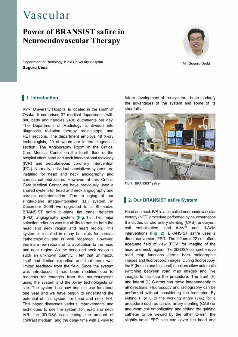
1. Introduction Kinki University Hospital is located in the south of Osaka. It comprises 37 medical departments with 800 beds and handles 2400 outpatients per day. The Department of Radiology is divided into diagnostic, radiation therapy, radioisotope, and PET sections. The department employs 48 X-ray technologists, 29 of whom are in the diagnostic section. The Angiography Room in the Critical Care Medical Center on the fourth floor of the hospital offers head and neck interventional radiology (IVR) and percutaneous coronary intervention (PCI). Normally, individual specialized systems are installed for head and neck angiography and cardiac catheterization. However, at this Critical Care Medical Center we have previously used a shared system for head and neck angiography and cardiac catheterization. Due to aging of our single-plane image-intensifier (I.I.) system, in December 2009 we upgraded to a Shimadzu BRANSIST safire bi-plane flat panel detector (FPD) angiography system (Fig. 1). The major selection criterion was the ability to handle both the head and neck region and heart region. This system is installed in many hospitals for cardiac catheterization and is well regarded. However, there are few reports of its application to the head and neck region. As the head and neck region is such an unknown quantity, I felt that Shimadzu itself had limited expertise and that there was limited feedback from the field. Since the system was introduced, it has been modified due to requests for changes from the neurosurgeons using the system and the X-ray technologists on site. The system has now been in use for about one year and we have begun to understand the potential of this system for head and neck IVR. This paper discusses various improvements and techniques to use the system for head and neck IVR, the 3D-DSA scan timing, the amount of contrast medium, and the delay time with a view to
future development of the system. I hope to clarify the advantages of the system and some of its shortfalls. Fig.1 BRANSIST safire
2. Our BRANSIST safire System Head and neck IVR is a so-called neuroendovascular therapy (NET) procedure performed by neurosurgeons. It includes carotid artery stenting (CAS), aneurysm coil embolization, and d-AVF and d-AVM interventions (Fig. 2). BRANSIST safire uses a direct-conversion FPD. The 22 cm × 22 cm offers adequate field of view (FOV) for imaging of the head and neck region. The 2D-DSA comprehensive road map functions permit both radiographic images and fluoroscopic images. During fluoroscopy, the F (frontal) and L (lateral) monitors allow automatic switching between road map images and live images to facilitate the procedure. The front (F) and lateral (L) C-arms can move independently in all directions. Fluoroscopy and radiography can be performed without considering the isocenter. By setting F or L to the working angle (WA) for a procedure such as carotid artery stenting (CAS) or aneurysm coil embolization and setting the guiding catheter to be viewed by the other C-arm, the slightly small FPD size can cover the head and

neck region. The high definition and contrast live up to the system's good reputation for image quality. However, the image quality seems too good with the standard settings and they probably result in excessive X-ray exposure. To minimize the exposure dose, we took measures such as adding a mode with Al 2.0 mm + Cu 0.1 mm to a mode with Al 1.5 mm as an additional filter inserted and offering selection of imaging modes with a low fluoroscopy or radiography rate. Table 1 shows the effects of the X-ray exposure dose reduction. Fig. 2 IVR Target Diseases in the Head and Neck Region (a) Carotid a. stenosis (b) Rt.ICA, ICPC aneurysm (c) Lt.CSF Table 1 Results of X-Ray Exposure Dose Reduction
3. 3D Angiography of the Head and Neck Region
Currently, different manufacturers or users use different names related to 3D angiography, including 3D-angio, 3D-DA, 3D rotational angiography, CT-like image, 3D-CT, cone-beam CT, and CBCT. This can lead to confusion. Table 2 gives a definition of the terms. I will proceed using the terms 3D-DA, 3D-DSA, and CT-like image. It is well known that the brain blood vessels have an anatomically complex branching structure. 3D imaging allows observations from all directions to reveal lesion structure and branching, permit size measurements, and offer information on determining the working angle. Consequently, it has become an essential function for performing NET. I often hear the opinion that 3D imaging is not necessary for
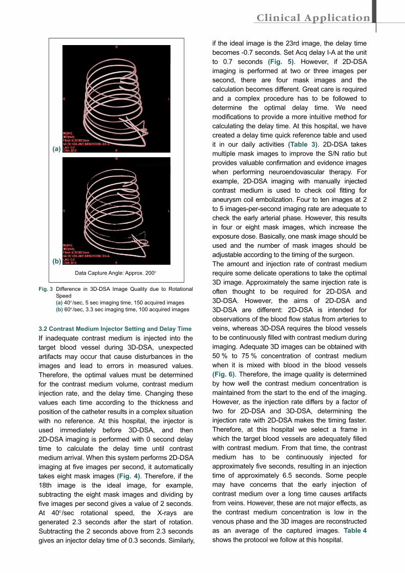
carotid artery stenting. However, we use 3D-imaging in all carotid artery stenting cases at this hospital. It allows determination of the angioguard XP landing point from internal and external carotid artery diameter measurements and selection of the optimal stent from these measured values and the length of the embolization site. Table 2 Definition of Terms 3.1 Rotational Speed of 3D-angiography The recommended conditions for 3D imaging with this system are 200° angle of rotation, 60°/sec rotational speed, 3.3 sec imaging time, and approximately 100 acquired images. However, before the new system was introduced, images at 60°/sec rotational speed did not make a good impression. Conditions of 40°/sec, 5 sec imaging time, and 150 acquired images was also available and offered a good image quality as indicated in comparison of the two images in Fig. 3. Therefore, we have selected imaging at 40°/sec at this hospital. Some people raised concerns about greater volumes of contrast medium or increased exposure dose. However, once a satisfactory 3D image has been obtained, the number of 2D-DSA imaging can be reduced, which results in an overall decrease in contrast medium volume and exposure dose. It would be good to change the mode to the one with 60°/sec in the future when improvements could offer equivalent image quality at 60°/sec and 40°/sec. The system offers both 3D-DA and 3D-DSA. Possibly due to the performance of the image reconstruction workstation, 3D-DA reconstruction image with no mask radiography results in cylindrical, dirt-like artifacts that make it difficult to set the threshold value, such that some noise remains in the images. 3D-DA is desirable from the exposure dose point of view. However, 3D-DSA is mainly used at this hospital, as it achieves superior S/N ratio and image quality and allows the addition of devices.
(a) (c)(b)
• Changing additional filters
• Head mode
Al 1.5 mm →Al 2.0 mm + Cu 0.1 mmAdjust input dose using density function. * Dose at IVR point
Base dose Standard setting Low-dose setting mGy/min 234.5 117 to 165Dose ratio 100 % 50 to 70 %
Fluoroscopy 10 pps → 7.5 ppsRadiography 2 fps, 3 fps added
・ 3D-angiography ◎ 3D-DA3D-rotational angiography3D-RA
・ Cone beam CT ◎ CT-like imageCone beam C-arm CTCone beam CTCBCT3D soft tissue image3D-CT
・ 3D-DSA image ◎ 3D-DSA
(a)
(b) Data Capture Angle: Approx. 200°
Fig. 3 Difference in 3D-DSA Image Quality due to Rotational
Speed (a) 40°/sec, 5 sec imaging time, 150 acquired images (b) 60°/sec, 3.3 sec imaging time, 100 acquired images 3.2 Contrast Medium Injector Setting and Delay Time If inadequate contrast medium is injected into the target blood vessel during 3D-DSA, unexpected artifacts may occur that cause disturbances in the images and lead to errors in measured values. Therefore, the optimal values must be determined for the contrast medium volume, contrast medium injection rate, and the delay time. Changing these values each time according to the thickness and position of the catheter results in a complex situation with no reference. At this hospital, the injector is used immediately before 3D-DSA, and then 2D-DSA imaging is performed with 0 second delay time to calculate the delay time until contrast medium arrival. When this system performs 2D-DSA imaging at five images per second, it automatically takes eight mask images (Fig. 4). Therefore, if the 18th image is the ideal image, for example, subtracting the eight mask images and dividing by five images per second gives a value of 2 seconds. At 40°/sec rotational speed, the X-rays are generated 2.3 seconds after the start of rotation. Subtracting the 2 seconds above from 2.3 seconds gives an injector delay time of 0.3 seconds. Similarly,
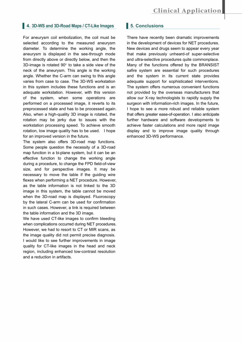
if the ideal image is the 23rd image, the delay time becomes -0.7 seconds. Set Acq delay I-A at the unit to 0.7 seconds (Fig. 5). However, if 2D-DSA imaging is performed at two or three images per second, there are four mask images and the calculation becomes different. Great care is required and a complex procedure has to be followed to determine the optimal delay time. We need modifications to provide a more intuitive method for calculating the delay time. At this hospital, we have created a delay time quick reference table and used it in our daily activities (Table 3). 2D-DSA takes multiple mask images to improve the S/N ratio but provides valuable confirmation and evidence images when performing neuroendovascular therapy. For example, 2D-DSA imaging with manually injected contrast medium is used to check coil fitting for aneurysm coil embolization. Four to ten images at 2 to 5 images-per-second imaging rate are adequate to check the early arterial phase. However, this results in four or eight mask images, which increase the exposure dose. Basically, one mask image should be used and the number of mask images should be adjustable according to the timing of the surgeon. The amount and injection rate of contrast medium require some delicate operations to take the optimal 3D image. Approximately the same injection rate is often thought to be required for 2D-DSA and 3D-DSA. However, the aims of 2D-DSA and 3D-DSA are different: 2D-DSA is intended for observations of the blood flow status from arteries to veins, whereas 3D-DSA requires the blood vessels to be continuously filled with contrast medium during imaging. Adequate 3D images can be obtained with 50 % to 75 % concentration of contrast medium when it is mixed with blood in the blood vessels (Fig. 6). Therefore, the image quality is determined by how well the contrast medium concentration is maintained from the start to the end of the imaging. However, as the injection rate differs by a factor of two for 2D-DSA and 3D-DSA, determining the injection rate with 2D-DSA makes the timing faster. Therefore, at this hospital we select a frame in which the target blood vessels are adequately filled with contrast medium. From that time, the contrast medium has to be continuously injected for approximately five seconds, resulting in an injection time of approximately 6.5 seconds. Some people may have concerns that the early injection of contrast medium over a long time causes artifacts from veins. However, these are not major effects, as the contrast medium concentration is low in the venous phase and the 3D images are reconstructed as an average of the captured images. Table 4 shows the protocol we follow at this hospital.
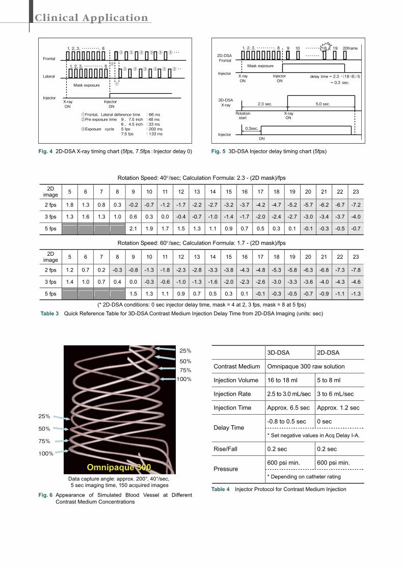
Fig. 4 2D-DSA X-ray timing chart (5fps, 7.5fps:Injector delay 0)
Fig. 6 Appearance of Simulated Blood Vessel at Different
Contrast Medium Concentrations
Fig. 5 3D-DSA Injector delay timing chart (5fps)
3D-DSA 2D-DSA
Contrast Medium Omnipaque 300 raw solution
Injection Volume 16 to 18 ml 5 to 8 ml
Injection Rate 2.5 to 3.0 mL/sec 3 to 6 mL/sec
Injection Time Approx. 6.5 sec Approx. 1.2 sec
-0.8 to 0.5 sec 0 sec Delay Time
* Set negative values in Acq Delay I-A.
Rise/Fall 0.2 sec 0.2 sec
600 psi min. 600 psi min. Pressure
* Depending on catheter rating
Table 4 Injector Protocol for Contrast Medium Injection
Rotation Speed: 40°/sec; Calculation Formula: 2.3 - (2D mask)/fps
2D image 5 6 7 8 9 10 11 12 13 14 15 16 17 18 19 20 21 22 23
2 fps 1.8 1.3 0.8 0.3 -0.2 -0.7 -1.2 -1.7 -2.2 -2.7 -3.2 -3.7 -4.2 -4.7 -5.2 -5.7 -6.2 -6.7 -7.2
3 fps 1.3 1.6 1.3 1.0 0.6 0.3 0.0 -0.4 -0.7 -1.0 -1.4 -1.7 -2.0 -2.4 -2.7 -3.0 -3.4 -3.7 -4.0
5 fps 2.1 1.9 1.7 1.5 1.3 1.1 0.9 0.7 0.5 0.3 0.1 -0.1 -0.3 -0.5 -0.7
Rotation Speed: 60°/sec; Calculation Formula: 1.7 - (2D mask)/fps
2D image 5 6 7 8 9 10 11 12 13 14 15 16 17 18 19 20 21 22 23
2 fps 1.2 0.7 0.2 -0.3 -0.8 -1.3 -1.8 -2.3 -2.8 -3.3 -3.8 -4.3 -4.8 -5.3 -5.8 -6.3 -6.8 -7.3 -7.8
3 fps 1.4 1.0 0.7 0.4 0.0 -0.3 -0.6 -1.0 -1.3 -1.6 -2.0 -2.3 -2.6 -3.0 -3.3 -3.6 -4.0 -4.3 -4.6
5 fps 1.5 1.3 1.1 0.9 0.7 0.5 0.3 0.1 -0.1 -0.3 -0.5 -0.7 -0.9 -1.1 -1.3
(* 2D-DSA conditions: 0 sec injector delay time, mask = 4 at 2, 3 fps, mask = 8 at 5 fps) Table 3 Quick Reference Table for 3D-DSA Contrast Medium Injection Delay Time from 2D-DSA Imaging (units: sec)
2D-DSAFrontal
Injectordelay time = 2.3 -(18-8)/5
= 0.3 sec.
X-rayON
InjectorON
Mask exposure
1,2,3,・・・・・・・・・,8 9 10 ・・・・・・・
・・・・・・・
18 19 20frame
3D-DSAX-ray
X-rayON
Injector
Rotationstart
2.3 sec.
0.3sec.
5.0 sec.
ON
Data capture angle: approx. 200°, 40°/sec,5 sec imaging time, 150 acquired images
Omnipaque 300Omnipaque 300
25%
50%
75%
100%
25%
50%75%100%
Frontal
Lateral
Injector
①Frontal,Lateral deference time :66 ms②Pre exposure time :48 ms
6 ,4.5 inch :33 ms③Exposure cycle :200 ms
7.5 fps :133 ms
①
X-rayON ON
Injector
②
③
③
③ ③
③ ③
③ ③・・・③
③ ③・・
Mask exposure
1,2,3,・・・・・・・・・,8
1,2,3,・・・・・・・・・,8③
9 ,7.5 inch
5 fps
4. 3D-WS and 3D-Road Maps / CT-Like Images For aneurysm coil embolization, the coil must be selected according to the measured aneurysm diameter. To determine the working angle, the aneurysm is displayed in the see-through mode from directly above or directly below, and then the 3D-image is rotated 90° to take a side view of the neck of the aneurysm. This angle is the working angle. Whether the C-arm can swing to this angle varies from case to case. The 3D-WS workstation in this system includes these functions and is an adequate workstation. However, with this version of the system, when some operations are performed on a processed image, it reverts to its preprocessed state and has to be processed again. Also, when a high-quality 3D image is rotated, the rotation may be jerky due to issues with the workstation processing speed. To achieve smooth rotation, low image quality has to be used. I hope for an improved version in the future. The system also offers 3D-road map functions. Some people question the necessity of a 3D-road map function in a bi-plane system, but it can be an effective function to change the working angle during a procedure, to change the FPD field-of-view size, and for perspective images. It may be necessary to move the table if the guiding wire flexes when performing a NET procedure. However, as the table information is not linked to the 3D image in this system, the table cannot be moved when the 3D-road map is displayed. Fluoroscopy by the lateral C-arm can be used for confirmation in such cases. However, a link is required between the table information and the 3D image. We have used CT-like images to confirm bleeding when complications occurred during NET procedures. However, we had to resort to CT or MIR scans, as the image quality did not permit precise diagnosis. I would like to see further improvements in image quality for CT-like images in the head and neck region, including enhanced low-contrast resolution and a reduction in artifacts.
5. Conclusions There have recently been dramatic improvements in the development of devices for NET procedures. New devices and drugs seem to appear every year that make previously unheard-of super-selective and ultra-selective procedures quite commonplace. Many of the functions offered by the BRANSIST safire system are essential for such procedures and the system in its current state provides adequate support for sophisticated interventions. The system offers numerous convenient functions not provided by the overseas manufacturers that allow our X-ray technologists to rapidly supply the surgeon with information-rich images. In the future, I hope to see a more robust and reliable system that offers greater ease-of-operation. I also anticipate further hardware and software developments to achieve faster calculations and more rapid image display and to improve image quality through enhanced 3D-WS performance.