Embed Size (px)
Citation preview

Power Monitor Products
Powermonitor 3000 Products (Bulletin 1404)
The Powermonitor 3000 has four versions, the M4, M5, M6, and the M8. The M4 unit provides basic metering including frequency, voltage, current, and power. It also
provides calculated information such as energy consumption, power factor, and total harmonic distortion. The unit also has onboard logging capability that can store
data, record the min and max of each parameter, and keep an event log.
The M5 offers M4 functionality with flash upgrade capabilities to higher levels. The M6 unit contains all of this functionality in addition to power quality features such
as, extensive waveform capture and storage and spectral analysis up to the 41st harmonic. The M8 adds more sophisticated power quality tools, greater speeds,
accuracy and captures sub-cycle transients as well as harmonic analysis up to the 63rd harmonic.
For more information, see publication 1404-PP005*.
Powermonitor 1000 Products (Bulletin 1408)
Energy management and understanding energy costs are a major focus today in the manufacturing industry. The Powermonitor 1000 is a cost effective energy
monitoring and control solution. The Powermonitor 1000 is perfect for your applications where load profiling, cost allocation, or energy control is required. It can also
provide seamless integration to your existing energy monitoring systems where sub-metering is required. The Powermonitor 1000 is available in five models (two
transducers, and three energy-monitors), with features and a price point to meet your application.
Transducer models feature the ability to measure voltage, current, and power related tags. Energy monitor models feature the ability to measure consumption related
tags such as real, reactive, and apparent energy. The top-of-the-line energy monitor (EM3) provides all the features of both the transducer and energy monitor models.
The Powermonitor 1000 integrates into your existing energy monitoring systems featuring, RSView, RSPower, or RSEnergyMetrix to further enhance the view into
energy costs. Your existing Allen‐Bradley PLC’s (PLC‐5®, SLC™, ControlLogix® Family) can also easily communicate to the Powermonitor 1000 to allow energy data to be
used in control systems.
For more information, see publication 1408-PP001*.
PowerPad Portable Powermonitor (Bulletin 1412)
Wouldn’t it be nice if you could look inside your electrical system and see what's going on? Troubleshooting would be so much easier if you could see the volts, amps,and harmonic content in real time and take pictures to document and analyze. Now you can do just that and more. The full-color graphical display lets you see and
analyze each signal clearly. Its high-speed sample rate, at 256 samples per cycle, provides excellent fidelity in reproducing waveforms and capturing transients that
happen as fast as 62.5 ms.
4 MB of memory is conveniently partitioned to let you store four different types of data, synchronized or independent of each other. You can store up to 12 screen
snapshots, up to 50 captured transients that contain four cycles for each active input, and 4096 alarm events. You can also record trend data for days, weeks, or even
months.
Additional sets of three current probes are available, including 240 A, 1200 A, 6 A/120 A clamp-on probes, 24 and 36 in. "rope" 6500 A current probes, and a single 1000
A AC/1400 A DC clamp-on probe.
For more information, see publication 1412-PP001*.
Current Transformers (Bulletin 1411)
The 1411 series is a full line of low-voltage Current Transformers (CTs) for various power measurement devices and applications.
Power measurement devices include protective relays, analog devices, transducers, and power monitors. The purpose of CTs is to scale high currents to more
manageable levels, while preserving a reasonable level of accuracy. CTs typically scale the currents flowing through their primaries to 5 amps (full scale) on their
secondaries. The majority of power measurement devices are designed to accept this current level.
Bulletin 1411 Current Transformers are available in ratios from 50:5 to 3500:5 in a variety of solid core, split core, and window sizes.
For more information, see publication 1411-SG001*.
Power Monitoring Software
There are three types of power monitoring software:
RSEnergyMetrix® software offers complete energy management for all utilities on a wide area network
RSPower™ and RSPower™Plus software offers simple integration of power monitoring information into an existing human machine interface
RSEnergyMetrix (Bulletin 9307-EM)
RSEnergyMetrix is a sophisticated web-enabled, energy management software that puts critical energy information at your desktop.

The RSEnergyMetrix software suite combines data communication, client‐server applications, and Microsoft’s advanced .NET™ web technology to provide you with acomplete energy-management solution.
With RSEnergyMetrix, you can capture, analyze, store, and share energy data across your entire enterprise via a LAN or WAN using a simple web browser. This makes it
a snap to distribute the knowledge you need to optimize energy consumption, which can help improve productivity while lowering energy costs.
Features and Benefits:
Scalable — Has the scalability to add components while maintaining your original investments.
RSEnergyMetrix Manager
RSEnergyMetrix RT, real-time view and configure
RSEnergyMetrix 3PX, 3rd-party OPC connectivity
RSEnergyMetrix ReportsPlus
RSEnergyMetrix ChartsPlus
Connectivity — Remote connectivity from PC to metering points.
Connectivity through RSLinx: RS-232, RS-485, Ethernet, DeviceNet, RIO passthru, optical, and modem (RSLinx Lite is included with the manager package)
Third part connectivity – with 3PX option via OPC
Configuration — RSEnergyMetrix provides easy and flexible configuration.
Configure water, air, gas, electricity, and steam meters or any energy or production related inputs
Configure Manual Meters as placeholders in the database for manual data entry
Configure user defined data sources such as standard PLC-5 or SLC hardware types or Generic OPC
Flexible configuration allows you to:
Create a model of your facility for utility accounting
Put meters in multiple groupings for cost allocation
Set and change meter configuration values remotely
Set multi-level password protection and privileges
Monitoring and Analysis — RSEnergyMetrix is a powerful load profiling, cost allocation and billing analysis tool.
Create energy budgets and forecasts
Compare and contrast alternative utility rates; do “whatif” for other rate structuresPrint and store all reports and charts
Software and Hardware Requirements for a Midrange Server:
Windows® 2003 (or 2000) Server or Advanced Server
Microsoft® SQL Server 2005 (or 2000 SP3a min) Standard or Enterprise
2 or 4 CPU 800+ MHz Pentium® III or better
1 GB RAM
30 GB hard disk (separate disk(s) for operating system/log files and RAID 5 for main database files preferred)
For more information, see technical data: ENEMTX-TD001*.
RSPower and RSPowerPlus Software
RSPower is a .NET/Windows-based software program that configures and displays data from all Rockwell Automation power monitors. RSPower is a complete tool that
allows you to save power monitor data to disk, print data, harmonics, and waveforms, and manage your power monitor configurations.
Install RSPower software and begin working with your power monitoring equipment from your desktop.
RSPower software provides quick and easy configuration, monitoring, and integration of power information.
Organize your Allen-Bradley power monitors into a graphical tree to represent your specific configuration or view the power monitors in a sorted list
Upload and download your power monitor configuration parameters from your PC
Save your entire site configuration as well as the individual data from each monitor
Continuous access to all power data from your PC
Display your data in pop-up views of real-time data
Display historical data stored within the power monitor
RSPower contains a browseable OPC server to simultaneously provide power monitor data to many external software packages
Flexible communications via RSLinx to communicate with power monitors RSPowerPlus provides additional reporting and trending features
RSPowerPlus provides the following additional features:

Run pre-configured monthly or yearly, billing or electrical consumption reports for each individual Powermonitor utilizing the TOU function in the Powermonitor 1000and 3000 family of products
Display real-time trending for up to five parameters simultaneously
Display historical trending for data directly from the trend log of each meter
User defined limits for monitoring of electrical parameters (i.e. demand monitoring)
For more information, see technical data RSPWR-TD002*.
Combination Generator Control Module (Bulletin 1407)
The Combination Generator Control Module (CGCM) sets a new standard for generator control. The CGCM combines excitation control, generator protection,
synchronization control, and full-featured metering in a single compact product. The CGCM, when used in conjunction with a ControlLogix® Automation Controller,
provides a highly robust and flexible platform for generator control and system supervision.
ControlNet port
Generator overvoltage (ANSI 59)
Four excitation control modes (AVR, FCR, PF and VAR)
Generator undervoltage (ANSI 27)
Adjustable soft start voltage buildup
Loss of sensing (ANSI 60FL)
OEL and UEL in AVR, VAR, and PF modes
Loss of PMG (ANSI 27)
Volts/Hertz compensation
Reverse VAR (ANSI 40Q)
Line drop compensation
Over frequency (ANSI 81O)
Auto-tracking between modes
Under frequency (ANSI 81U)
Redundant CGCM auto-tracking and auto-transfer
Reverse power (ANSI 32R)
Generator paralleling with droop or cross-current compensation
Rotating diode monitor (ANSI 58)
Generator paralleling with real power load sharing
Phase rotation error (ANSI 47)
Synchronizing for one or two breakers
Generator over current (ANSI 51/27F)
Loss of excitation current (ANSI 40)
Over excitation voltage (ANSI 59F)
Metering functions: Voltage, Current, Frequency, Power, Power Factor, Energy, Excitation Current and Voltage
Synchronization parameters include: Frequency, Phase Rotation, Phase Angle, Voltage Magnitude
For more information, see publication 1407-PP001*.

Capacitor Bank Controller (Bulletin 1413)
The capacitor bank controller is a pre-engineered control system containing a MicroLogix 1400 controller, one or more Powermonitor 1000 products, and an optional
human-machine interface(HMI). Pre-engineered ladder logic code in the controller gathers real and reactive power data from up to four power feeds(utility feeds and/or
generators). The logic operates on the data in standard engineering units of kVAR and kW and minimizes imported and exported reactive power by switching up to 10
steps of capacitance. This strategy controls power factor while reducing the likelihood of voltage surge caused by excessive kVAR export.
Functions:
Autoconfigure
Manual configure
Discharge timer on each step
Selectable operating modes
Manual operation
First In, Last Out (FILO)
Balanced, level-out usage of capacitor steps
Best fit, finds best match of capacitor step to system kVAR needs
Alarms
Bad step, indicates blown fuse, capacitor failure
Target power factor not achieved
High/Low voltage
Metering
Communication loss
Powermonitor data concentrated into the MicroLogix 1400 controller
Phase current, line voltage, frequency, real and reactive power, and power factor
Options
Up to three additional Powermonitor 1000 meters to aggregate up to four total feeds
The PanelView Component C600 Touch HMI terminal with Ethernet communication provides ease of navigation, viewing, and configuration of the capacitor bankcontroller application
Powermonitor™ Products
Our Powermonitor products meet the needs of producers and consumers of electric power. These products provide monitoring and control information for substation
and distribution centers, electrical control panels, and many utility, commercial, and industrial applications including motor control centers.
The following power management application definitions help explain the advantages of using power monitoring products.
Demand management is a control system designed to minimize electrical demand penalties that can represent up to 30% of a typical industrial utility bill.
Activity-based cost accounting is a management system that allows a customer to allocate energy costs based on actual usage, which is based on sub-metering rather
than other measurements such as square footage allocation.
Power control is a control system where electricity is the process output. There is usually on-site generation, emergency load shedding, or a system where a high-
quality and stable electric power source is critical to the process.
Power quality is a management system that monitors power quality events or conditions that could cause a production shutdown like voltage sags, brownouts,
transients, and high harmonic distortion.
Load profiling is a management system where electrical loads are monitored or profiled. These load profiles let the user prepare for utility deregulation and make fact-
based decisions on future demand-side management control systems.

Power Monitoring Product and Features
Powermonitor™ 3000 (Bulletin 1404)Compact size
Oscillography, harmonic analysis, and transient detection
Multiple communication options
Various update rates
Configurable logs up to 45000 parameters deep
Time stamp data logging of system measurements and events
Powermonitor™ 1000 (Bulletin 1408)Compact size
Multiple communication options
Integrated LCD display
Wiring diagnostics
Time of use (on-peak, off-peak)
Integral data logs
Integral web page
PowerPad Portable Powermonitor™ (Bulletin 1412)Measures true RMS AC voltage, current, and power
Single phase, three phase, and DC
Capture and display harmonics to the 50th order
Capture transients down to 1/256th of a cycle
Waveform and phasor diagram display
Harmonic data including THD, crest factor, K-factor
Time-stamped record of alarms, surges, and sags
Optically isolated RS-232 communication port
Includes software for data storage, analysis, and reports
Current Transformer (Bulletin 1411)Low voltage (600 V AC)
Metering grade
Variety of types including round, rectangular, and split-core
Power Monitoring Software (Bulletin 9307)RSEnergyMetrix
®
RSPower
™
Combination Generator Control Module (Bulletin 1407)Generator protection
Excitation control
Synchronization control
Full featured metering
Integration with Allen-Bradley ControlLogix family
Capacitor Bank Controller (Bulletin 1413)PLC-based Capacitor bank control
Power factor correction
Auto or manual step size configuration
Selectable operating modes
Alarms
Powermonitor 3000

Environmental
Operating Temperature, Ambient 1404-MX05X-000, DNT, 1404-DM –20…+60 °C (–4…+140 °F)
1404-MX05X-RIO, RS232, ENT 0…55 °C (32…132 °F)
Storage Temperature –40…+85 °C (–40…+185 °F)
Humidity 5…95% non‐condensing
Vibration 10…500 Hz operational: 2 g (±0.012 in.)non-operational: 2.5 g (±0.015 in.)
Shock 1/2 sine pulse, 11 ms duration
operational: 30 gnon-operational: 30 g
Input and Output Ratings
Control Power Input 120/240V AC 50/60Hz or 125/250V DC
Voltage Input Impedance 1 MW min., 399V AC max.V1, V2, and V3 to N
Current Sense Inputs Overload withstand: 15 A continuous, 200 A for 1 sBurden: 0.05 VAImpedance: 0.002 WMaximum crest factor (at 5 A): 3.0
Status Inputs Contact closure (internal 24V DC)
Control Relay Output ANSI C37.90-1989
KYZ Output Solid‐state KYZ = 80 mA at 240…300V DC
Operational Data
Nominal Range
Voltage 347V600V
15…399V L-N rms
26…691V L-L rms
Current 5 A 50 mA…10.6 A rms
Frequency 50 or 60 Hz 40…75 Hz
Metering by model type
M4 M5 M6 M8
Accuracy
Voltage ±0.2% ±0.05% ±0.05% ±0.05%
Current ±0.2% ±0.05% ±0.05% ±0.05%
Frequency ±0.05 Hz ±0.05 Hz ±0.05 Hz ±0.05 Hz
Power ±0.4% ±0.1% ±0.1% ±0.1%
Energy Class 1.0 - ANSI C12.16 Class 0.5 - ANSI C12.20 / EN 60687, Class 0.2 also available
Features
Configurable Setpoints 10 10 20 20
Waveform Captures — — 8 2
Harmonic Analysis
Order — — 41st 63rd
%THD X X X X
TIF — — X X
K-factor X X X X
Crest factor — — X X
IEEE 519 Compliance — — X X
Transient Detection — — — X
Powermonitor 1000
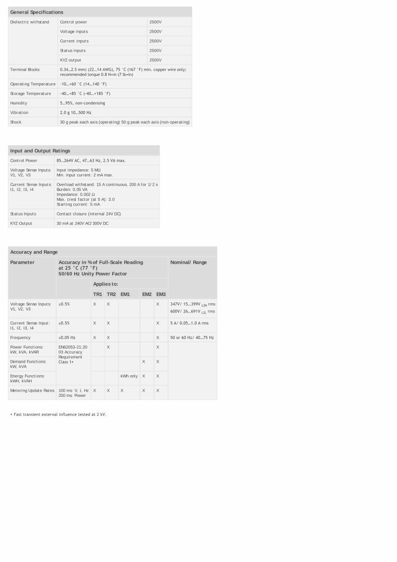
General Specifications
Dielectric withstand Control power 2500V
Voltage inputs 2500V
Current inputs 2500V
Status inputs 2500V
KYZ output 2500V
Terminal Blocks 0.34…2.5 mm2 (22…14 AWG), 75 °C (167 °F) min. copper wire only;recommended torque 0.8 N•m (7 lb•in)
Operating Temperature ‐10…+60 °C (14…140 °F)
Storage Temperature ‐40…+85 °C (‐40…+185 °F)
Humidity 5…95%, non‐condensing
Vibration 2.0 g 10…500 Hz
Shock 30 g peak each axis (operating) 50 g peak each axis (non-operating)
Input and Output Ratings
Control Power 85…264V AC, 47…63 Hz, 2.5 VA max.
Voltage Sense Inputs:V1, V2, V3
Input impedance: 5 MWMin. input current: 2 mA max.
Current Sense Inputs:I1, I2, I3, I4
Overload withstand: 15 A continuous, 200 A for 1/2 sBurden: 0.05 VAImpedance: 0.002 WMax. crest factor (at 5 A): 3.0Starting current: 5 mA
Status Inputs Contact closure (internal 24V DC)
KYZ Output 30 mA at 240V AC/300V DC
Accuracy and Range
Parameter Accuracy in % of Full-Scale Reading at 25 °C (77 °F)50/60 Hz Unity Power Factor
Nominal/ Range
Applies to:
TR1 TR2 EM1 EM2 EM3
Voltage Sense Inputs:V1, V2, V3
±0.5% X X X 347V/ 15…399V L N rms
600V/ 26…691V L L rms
Current Sense Input:I1, I2, I3, I4
±0.5% X X X 5 A/ 0.05…1.0 A rms
Frequency ±0.05 Hz X X X 50 or 60 Hz/ 40…75 Hz
Power Functions:kW, kVA, kVAR
EN62053-21:2003 AccuracyRequirementClass 1⋆
X X
Demand Functions:kW, kVA
X X
Energy Functions:kWH, kVAH
kWh only X X
Metering Update Rates 100 ms: V, I, Hz200 ms: Power
X X X X X
⋆ Fast transient external influence tested at 2 kV.

Measured Parameters by model type
Logged Parameters TR1 TR2 EM1 EM2 EM3
Voltage X X X
Current X X X
Frequency X X X
Voltage Unbalance X X X
Current Unbalance X X X
Real Power [kW] X X
Reactive Power [kVAR] X X
Apparent Power [kVA] X X
True Power Factor X X
Real Energy [kWh] X X X
Reactive Energy [kVARh] X X
Apparent Energy [kVAHh] X X
Real Power Demand [kW] X X
Reactive Power Demand [kVAR] X X
Apparent Power Demand [kVA] X X
Projected Real Power [kW ] X X
Projected Reactive Power [kVAR] X X
Projected Apparent Power [kVA] X X
Demand Power Factor X X
Logs TR1 TR2 EM1 EM2 EM3
Energy Log X X X
Minimum/Maximum Log X X X X
Load Factor Log X X
Status Log X X X X X
PowerPad Portable Powermonitor

Electrical
Sampling Frequency 256 samples per cycle
Data Storage 4 MB partitioned for waveforms, transients, alarms, and trend recording
Voltage (TRMS) Phase-to-Phase: 830VPhase-to-Neutral: 480V
Current (TRMS) 240 A Clamp: 0…6 A/120 A or 0…240 A1000 A AC/1400 A DC Clamp: 0…1000 A AC, 0…1400 A DC
1200 A Clamp: 0…1200 A6500 A Clamp: 0…6500 A⋆
Measurement Range Resolution Accuracy
Single-Phase RMS Voltages 6…480V 0.1V ±0.5% ±2cts
Phase-to-Phase RMS Voltages 10…830V 0.1V ±0.5% ±2cts
Single-Phase Peak Voltages 6…680V 1V ±(1% ±5cts)
Phase-to-Phase Peak Voltages 10…1360V 1V ±(1% ±5cts)
Frequency (Hz) 40…69 Hz 0.01 Hz ±0.01 Hz
DC Voltage Component 6…650V 0.1V ±1% ±2cts
Current Probes (Arms)–MN Clamp–SR Clamp–AmpFlex™ Probe
0…240 A0…1200 A10…6500 A
0.1 A0.1 A; 1…1000 A0.1 A; 1…1000 A
±(0.5% + 2 cts)±(0.5% + 2 cts)±(0.5% + 1 A)
Active (Real) Power (kW) 0…9999 kW Four digits (10 000ct) ±1% ±1ct @ PF ³ 0.8
Reactive Power (kVAR) 0…9999 kVAR Four digits (10 000ct) ±1% ±1ct @ PF £ 0.8
Apparent Power (kVA) 0…9999 kVA Four digits (10 000ct) ±1% ±1ct
Power Factor (PF & DPF) ‐1.000…1.000 0.001 ±(1.5% + 0.01)
Active Energy (kWh) 0…9999 MWh Four digits (10 000ct) ±1% ±1ct @ PF ³ 0.8
Reactive Energy (kVARh) 0…9999 MVARh Four digits (10 000ct) ±1% ±1ct @ PF £ 0.8
Apparent Energy (kVAh) 0…9999 MVAh Four digits (10 000ct) ±1% ±1ct
Unbalance (V & A) 0…100% 0.1% ±1% ±1ct
Phase Angles (V-A, A-A, V-V) ‐179…180° 1° ±2° ±1ct
Harmonics (1…50)F=40…69Hz (V ³ 50V, A > Inom/100
0…999% 0.1% ±1% + 5ct
Total Harmonic Distortion (V & A) 0…999% 0.1% ±1% + 5ct
K-factor (Akf) 1…99.99 0.01 ±5% ±1ct
Flicker (Pst) 0.00…9.99 0.01 –
Power Source 9.6V NiMH rechargeable battery packAC supply: 110/230VAC ±20% (50/60Hz)
Battery Life 6 hours with display on; £96 hrs with display off (record mode)
Environmental
Operating Temperature 0…50 °C (32…122 °F)
Storage Temperature ‐20…+50 °C (‐4…+122 °F)
Mechanical
Display 1/4 VGA (320 x 240) color LCD
Dimensions 240 x 180 x 55 mm (9.5 x 7 x 2 in.)
Weight 2.1 kg (4.6 lb)
Safety
Safety Rating EN 61010-1, 600V Cat. III, Pollution Degree 2
Double Insulation Yes
CE Mark Yes
⋆ Crest Factor at 6500 A = 1
Current Transformers
Core Type Split or solid
Current Ratio Range 50:5…6000:5
Burden Range 1…200 VA
Window Sizes Round Window: 1.00", 2.5", 1.13", 3.25", 1.47", 5.75", 2.31", 6.31", 8.25" Rectangular Window: 2.00 x 5.5", 0.75 x 0.75", 4.5 x 4.5", 1.3 x 1.6", 1.42 x 1.53", 1.3 x 2.15", 2.75 x 2.7", 2 x 3.5", 2.6 x 6.25"
Certifications UL, CSA
Standards ANSI/IEEE C57.13, IEC 44-1
RSPower Software

System Hardware Requirements
Compatible Microprocessor Pentium 4 or P4
RAM 256 MB
Hard Disk 100 MB of available space
Drive CD-ROM/DVD-ROM
Disk Drive 3.5 inch, 1.44 MB
Operating System Windows 2000, Windows 2000 Server, Windows XP, or Windows Server 2003
Microsoft .NET Framework 2.0
Application Adobe Acrobat Reader
Communication Type RSLinx Classic 2.51 OEM or higher (if not bundled with communications drivers)
Communication Interface Appropriate communications interface to the Powermonitor
Devices Bulletin 1400 Powermonitor, 1403 Powermonitor II, 1404 Powermonitor 3000, 1408 Powermonitor 1000
External Connections Serial, Ethernet, ControlNet™, DeviceNet™ or Remote I/O connection to the power monitor
Combination Generator Control Module
Operating Power Requirements
Source No. of Phases Wiring Configuration Voltage Frequency VA (max.)
Permanent Magnet Generator 1 PMG-A & PMG-C Min: 56V rmsMax: 300V rms
Min: 50 HzMax: 342 Hz
3070
3 Floating wye Min: 56V L L rms
Max: 300V L L rms
Separately Excited 1 PMG-A & PMG-C Min: 56V rmsMax: 300V rms
3 Floating wye Min: 56V L L rms
Max: 300V L L rms
3 Grounded wye(grounded neutral)
Min: 56V L L rms
Max: 300V L L rms
3 Floating delta Min: 56V L-L rms
3 Open delta, floating Min: 56V L L rms
Max: 300V L L rms
Generator and Bus Voltage Sensing Values
No. of Phases Wiring Configuration Grounded Connection Available Voltage Frequency
1 VA & VC No Min: 57V rmsMax: 150V rms
Min: 20 HzMax: 90 Hz
3 Floating wye No Min: 99V L L rms
Max: 208V L L rms
1 Grounded wye Yes Min: 99V L L rms
Max: 208V L L rms
3 Open delta, grounded "B" phase Yes Min: 99V L L rms
Max: 208V L L rms
Generator Current Sensing
Type Three-phase plus cross current compensation input
Frequency 50/60 Hz
Range 1 or 5 A maximum continuous
Burden <0.1 VA per phase for metering CTs<2.5 VA per phase for cross current inputs
3 Phase Open delta, grounded "B" phase

Field Output
Continuous Voltage 32, 63, or 125V DC
Continuous Current 15 A DC
10 second Forcing Voltage 50, 100, or 200V DC
10 second Forcing Current 30 A DC
Powermonitor 3000 (Bulletin 1404)
(1404‐M4, M5, M6, and M8) — 120/240 Volt Power Supply Option
Description Cat. No.
Powermonitor 3000 Display Module 1404-DM
M4 Monitors
RS-485 1404-M405A-000
RS-485 and RS-232 1404-M405A-232
RS-485 and ControlNet 1404-M405A-CNT
RS-485 and DeviceNet 1404-M405A-DNT
RS-485 and Remote I/O 1404-M405A-RIO
RS-485 and Ethernet 1404-M405A-ENT
M5 Monitors
RS-485 1404-M505A-000
RS-485 and RS-232 1404-M505A-232
RS-485 and ControlNet 1404-M505A-CNT
RS-485 and DeviceNet 1404-M505A-DNT
RS-485 and Remote I/O 1404-M505A-RIO
RS-485 and Ethernet 1404-M505A-ENT
M6 Monitors
RS-485 1404-M605A-000
RS-485 and RS-232 1404-M605A-232
RS-485 and ControlNet 1404-M605A-CNT
RS-485 and DeviceNet 1404-M605A-DNT
RS-485 and Remote I/O 1404-M605A-RIO
RS-485 and Ethernet 1404-M605A-ENT
M8 Monitors
RS-485 1404-M805A-000
RS-485 and RS-232 1404-M805A-232
RS-485 and ControlNet 1404-M805A-CNT
RS-485 and DeviceNet 1404-M805A-DNT
RS-485 and Remote I/O 1404-M805A-RIO
RS-485 and Ethernet 1404-M805A-ENT

(1404‐M4, M5, M6, and M8) — 24 Volt Power Supply Option
Description Cat. No.
M4 Monitors
RS-485 1404-M405B-000
RS-485 and RS-232 1404-M405B-232
RS-485 and ControlNet 1404-M405B-CNT
RS-485 and DeviceNet 1404-M405B-DNT
RS-485 and Remote I/O 1404-M405B-RIO
RS-485 and Ethernet 1404-M405B-ENT
M5 Monitors
RS-485 1404-M505B-000
RS-485 and RS-232 1404-M505B-232
RS-485 and ControlNet 1404-M505B-CNT
RS-485 and DeviceNet 1404-M505B-DNT
RS-485 and Remote I/O 1404-M505B-RIO
RS-485 and Ethernet 1404-M505B-ENT
M6 Monitors
RS-485 1404-M605B-000
RS-485 and RS-232 1404-M605B-232
RS-485 and ControlNet 1404-M605B-CNT
RS-485 and DeviceNet 1404-M605B-DNT
RS-485 and Remote I/O 1404-M605B-RIO
RS-485 and Ethernet 1404-M605B-ENT
M8 Monitors
RS-485 1404-M805B-000
RS-485 and RS-232 1404-M805B-232
RS-485 and ControlNet 1404-M805B-CNT
RS-485 and DeviceNet 1404-M805B-DNT
RS-485 and Remote I/O 1404-M805B-RIO
RS-485 and Ethernet 1404-M805B-ENT
(1404) — 120/240 Volt Power Supply/Class 2 Option⋆
Description Cat. No.
M5 Monitors
RS-485 1404-M505A-000-02
RS-485 and RS-232 1404-M505A-232-02
RS-485 and ControlNet 1404-M505A-CNT-02
RS-485 and DeviceNet 1404-M505A-DNT-02
RS-485 and Remote I/O 1404-M505A-RIO-02
RS-485 and Ethernet 1404-M505A-ENT-02
M6 Monitors
RS-485 1404-M605A-000-02
RS-485 and RS-232 1404-M605A-232-02
RS-485 and ControlNet 1404-M605A-CNT-02
RS-485 and DeviceNet 1404-M605A-DNT-02
RS-485 and Remote I/O 1404-M605A-RIO-02
RS-485 and Ethernet 1404-M605A-ENT-02
M8 Monitors
RS-485 1404-M805A-000-02
RS-485 and RS-232 1404-M805A-232-02
RS-485 and ControlNet 1404-M805A-CNT-02
RS-485 and DeviceNet 1404-M805A-DNT-02
RS-485 and Remote I/O 1404-M805A-RIO-02
RS-485 and Ethernet 1404-M805A-ENT-02
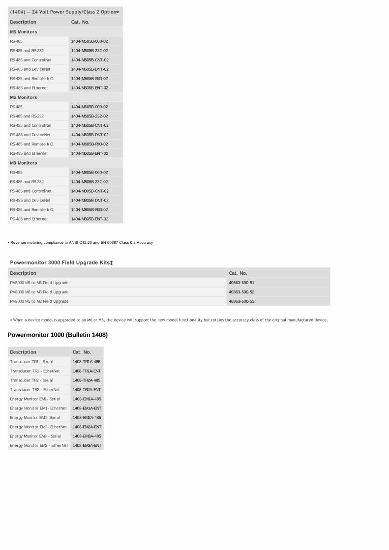
(1404) — 24 Volt Power Supply/Class 2 Option⋆
Description Cat. No.
M5 Monitors
RS-485 1404-M505B-000-02
RS-485 and RS-232 1404-M505B-232-02
RS-485 and ControlNet 1404-M505B-CNT-02
RS-485 and DeviceNet 1404-M505B-DNT-02
RS-485 and Remote I/O 1404-M505B-RIO-02
RS-485 and Ethernet 1404-M505B-ENT-02
M6 Monitors
RS-485 1404-M605B-000-02
RS-485 and RS-232 1404-M605B-232-02
RS-485 and ControlNet 1404-M605B-CNT-02
RS-485 and DeviceNet 1404-M605B-DNT-02
RS-485 and Remote I/O 1404-M605B-RIO-02
RS-485 and Ethernet 1404-M605B-ENT-02
M8 Monitors
RS-485 1404-M805B-000-02
RS-485 and RS-232 1404-M805B-232-02
RS-485 and ControlNet 1404-M805B-CNT-02
RS-485 and DeviceNet 1404-M805B-DNT-02
RS-485 and Remote I/O 1404-M805B-RIO-02
RS-485 and Ethernet 1404-M805B-ENT-02
⋆ Revenue metering compliance to ANSI C12.20 and EN 60687 Class 0.2 Accuracy
Powermonitor 3000 Field Upgrade Kits‡
Description Cat. No.
PM3000 M5 to M6 Field Upgrade 40863-600-51
PM3000 M6 to M8 Field Upgrade 40863-600-52
PM3000 M5 to M8 Field Upgrade 40863-600-53
‡ When a device model is upgraded to an M6 or M8, the device will support the new model functionality but retains the accuracy class of the original manufactured device.
Powermonitor 1000 (Bulletin 1408)
Description Cat. No.
Transducer TR1 - Serial 1408-TR1A-485
Transducer TR1 - EtherNet 1408-TR1A-ENT
Transducer TR2 - Serial 1408-TR2A-485
Transducer TR2 - EtherNet 1408-TR2A-ENT
Energy Monitor EM1- Serial 1408-EM1A-485
Energy Monitor EM1- EtherNet 1408-EM1A-ENT
Energy Monitor EM2- Serial 1408-EM2A-485
Energy Monitor EM2- EtherNet 1408-EM2A-ENT
Energy Monitor EM3 - Serial 1408-EM3A-485
Energy Monitor EM3 - EtherNet 1408-EM3A-ENT

Powermonitor 1000 Field Upgrade Kits
Description Cat. No.
PM 1000 485 to ENT Field Upgrade 1408-UP485-ENT
PM 1000 EM1 to EM3 Field Upgrade 1408-UPE1-E3
PM 1000 EM2 to EM3 Field Upgrade 1408-UPE2-E3
PM 1000 TR1 to EM3 Field Upgrade 1408-UPT1-E3
PM 1000 TR2 to EM3 Field Upgrade 1408-UPT2-E3
PowerPad Portable Power Monitor (Bulletin 1412)
Description Cat. No.
PowerPad Portable Powermonitor w/ 240 A Probes 1412-PP2127-48
PowerPad Portable Powermonitor w/ 1200 A Probes 1412-PP2127-49
PowerPad Portable Powermonitor w/ 24 in., 6500 A Probes 1412-PP2127-50
PowerPad Portable Powermonitor w/ 36 in., 6500 A Probes 1412-PP2127-51
PowerPad Portable Power Monitor Accessories
Description Cat. No.
Set of three probes (240 A) 1412-PP2137-01
Set of three probes (1200 A) 1412-PP2137-02
Set of three 24 in. probes (6500 A) 1412-PP2137-03
Set of three 36 in. probes (6500 A) 1412-PP2137-04
One probe (1000 A AC/1400 A DC) 1412-PP2137-05
Set of three probes (6/120 A) 1412-PP2137-06
Current Transformers — Split Core (Bulletin 1411) for Energy Management Systems and Instrumentation

Current Ratio Burden [VA] ANSI Metering Class Accuracy Cat. No.
B0.1 B0.2 B0.5
2.00 x 5.50 in. window size
250:5 1.5 4.8 — — — 1411-600-251
300:5 2.0 2.4 — — — 1411-600-301
400:5 1.5 2.4 4.8 — — 1411-600-401
500:5 2.0 2.4 4.8 — — 1411-600-501
600:5 2.5 2.4 2.4 — — 1411-600-601
800:5 5.0 1.2 1.2 2.4 — 1411-600-801
1000:5 7.5 1.2 1.2 2.4 — 1411-600-102
1200:5 15 0.6 1.2 1.2 — 1411-600-122
1500:5 20 0.6 0.6 1.2 — 1411-600-152
1600:5 20 0.6 0.6 1.2 — 1411-600-162
2000:5 30 0.6 0.6 0.6 — 1411-600-202
4.50 x 4.50 in. window size
400:5 1.0 4.8 — — — 1411-601-401
500:5 1.5 4.8 4.8 — — 1411-601-501
600:5 2.0 2.4 4.8 — — 1411-601-601
800:5 2.5 1.2 2.4 4.8 — 1411-601-801
1000:5 5.0 1.2 1.2 4.8 — 1411-601-102
1200:5 10.0 1.2 1.2 2.4 — 1411-601-122
1500:5 15.0 1.2 1.2 1.2 — 1411-601-152
1600:5 15.0 1.2 1.2 1.2 — 1411-601-162
2000:5 20.0 0.6 0.6 1.2 — 1411-601-202
1.42 x 1.53 in. window size
100:5 1.0 — — — ±5% 1411-604-101
150:5 1.0 — — — ±4% 1411-604-151
200:5 1.0 — — — ±2% 1411-604-201
250:5 2.0 — — — ±2% 1411-604-251
300:5 2.0 — — — ±1.5% 1411-604-301
400:5 2.5 — — — ±1.5% 1411-604-401
2.75 x 2.70 in. window size (weatherproof)
200:5 2.5 — — — 2% 1411-606-201
250:5 3.0 — — — 1% 1411-606-251
300:5 3.5 — — — 1% 1411-606-301
350:5 4.0 — — — 1% 1411-606-351
400:5 5.0 — — — 1% 1411-606-401
500:5 6.0 — — — 1% 1411-606-501
600:5 8.0 — — — 1% 1411-606-601
750:5 10 — — — 1% 1411-606-751
800:5 12 — — — 1% 1411-606-801
1000:5 15 — — — 1% 1411-606-102
1200:5 20 — — — 1% 1411-606-122

Current Ratio Burden [VA] ANSI Metering Class Accuracy Cat. No.
B0.1 B0.2 B0.5
2.60 x 6.25 in. window size (weatherproof)
500:5 6.0 — — — ±1% 1411-608-501
600:5 8.0 — — — ±1% 1411-608-601
800:5 12 — — — ±1% 1411-608-801
1000:5 13 — — — ±1% 1411-608-102
1200:5 16 — — — ±1% 1411-608-122
1500:5 25 — — — ±1% 1411-608-152
1600:5 27 — — — ±1% 1411-608-162
2000:5 33 — — — ±1% 1411-608-202
2500:5 42 — — — ±1% 1411-608-252
3000:5 50 — — — ±1% 1411-608-302
3200:5 54 — — — ±1% 1411-608-322
0.75 x 0.75 in. window size (clamp-on)
100:0.1 5 W — — — ±1% 1411-614-101-01
200:0.1 5 W — — — ±1% 1411-614-201-01
1.30 x 1.60 in. window size (clamp-on)
100:5 1.0 — — — ±5% 1411-615-101
200:5 2.0 — — — ±3% 1411-615-201
300:5 3.5 — — — ±1% 1411-615-301
400:5 8.5 — — — ±1% 1411-615-401
200:1 1.5 — — — ±1% 1411-615-201-1
1.30 x 2.15 in. window size (clamp-on)
200:5 2.0 — — — ±3% 1411-616-201
400:5 5.0 — — — ±1% 1411-616-401
800:5 5.0 — — — ±1% 1411-616-801
400:0.1 5 W — — — ±1% 1411-616-401-01
2.00 x 3.50 in. window size
400:5 1.0 2.4 4.8 — — 1411-617-401
500:5 2.0 2.4 4.8 — — 1411-617-501
600:5 2.5 2.4 2.4 — — 1411-617-601
800:5 5.0 1.2 1.2 2.4 — 1411-617-801
1000:5 7.5 1.2 1.2 2.4 — 1411-617-102
1200:5 15.0 0.6 1.2 1.2 — 1411-617-122
Current Transformers — Solid Core (Bulletin 1411)
Current Ratio Burden [VA] ANSI Metering Class Cat. No.
B0.1 B0.2 B0.5 B0.9 B1.8
5.75 in. dia. window size (for relay and metering)
600:5 — 0.3 0.3 0.3 0.6 0.6 1411-120-601
800:5 — 0.3 0.3 0.3 0.3 0.6 1411-120-801
1000:5 — 0.3 0.3 0.3 0.3 0.6 1411-120-102
1200:5 — 0.3 0.3 0.3 0.3 0.3 1411-120-122
1500:5 — 0.3 0.3 0.3 0.3 0.3 1411-120-152
1600:5 — 0.3 0.3 0.3 0.3 0.3 1411-120-162
2000:5 — 0.3 0.3 0.3 0.3 0.3 1411-120-202
2500:5 — 0.3 0.3 0.3 0.3 0.3 1411-120-252
3000:5 — 0.3 0.3 0.3 0.3 0.3 1411-120-302
4000:5 — 0.3 0.3 0.3 0.3 0.3 1411-120-402
6.31 in. dia. window size (for metering)
1000:5 — 0.3 0.3 0.3 0.6 1.2 1411-125-102
1200:5 — 0.3 0.3 0.3 0.6 1.2 1411-125-122
1500:5 — 0.3 0.3 0.3 0.3 0.6 1411-125-152
1600:5 — 0.3 0.3 0.3 0.3 0.6 1411-125-162

2000:5 — 0.3 0.3 0.3 0.3 0.6 1411-125-202
2500:5 — 0.3 0.3 0.3 0.3 0.6 1411-125-252
3000:5 — 0.3 0.3 0.3 0.3 0.6 1411-125-302
3500:5 — 0.3 0.3 0.3 0.3 0.3 1411-125-352
4000:5 — 0.3 0.3 0.3 0.3 0.3 1411-125-402
0.25 in. dia. window size (for metering)
400:5 4.0 0.6 1.2 2.4 2.4 4.8 1411-126-401
500:5 7.5 0.6 0.6 1.2 2.4 2.4 1411-126-501
600:5 10 0.6 0.6 1.2 2.4 2.4 1411-126-601
800:5 20 0.3 0.3 0.6 0.6 1.2 1411-126-801
1000:5 25 0.3 0.3 0.6 0.6 1.2 1411-126-102
1200:5 40 0.3 0.3 0.3 0.6 0.6 1411-126-122
1500:5 50 0.3 0.3 0.3 0.3 0.6 1411-126-152
1600:5 50 0.3 0.3 0.3 0.3 0.6 1411-126-162
2000:5 60 0.3 0.3 0.3 0.3 0.3 1411-126-202
2500:5 75 0.3 0.3 0.3 0.3 0.3 1411-126-252
3000:5 90 0.3 0.3 0.3 0.3 0.3 1411-126-302
3200:5 95 0.3 0.3 0.3 0.3 0.3 1411-126-322
3500:5 100 0.3 0.3 0.3 0.3 0.3 1411-126-352
4000:5 125 0.3 0.3 0.3 0.3 0.3 1411-126-402
5000:5 140 0.3 0.3 0.3 0.3 0.3 1411-126-502
6000:5 140 0.3 0.3 0.3 0.3 0.3 1411-126-602
2.50 in. dia. with round exterior (for relay and metering)
50:5 1.5 2.4 — — — — 1411-180RL-500
75:5 2.5 1.2 2.4 — — — 1411-180RL-750
100:5 2.5 1.2 2.4 4.8 — — 1411-180RL-101
150:5 5.0 0.6 1.2 2.4 4.8 — 1411-180RL-151
200:5 12.5 0.6 0.6 1.2 2.4 — 1411-180RL-201
250:5 12.5 0.3 0.3 0.6 1.2 — 1411-180RL-251
300:5 25 0.3 0.3 0.6 1.2 2.4 1411-180RL-301
400:5 50 0.3 0.3 0.3 0.6 1.2 1411-180RL-401
500:5 50 0.3 0.3 0.3 0.6 1.2 1411-180RL-501
600:5 50 0.3 0.3 0.3 0.6 1.2 1411-180RL-601
750:5 50 0.3 0.3 0.3 0.6 1.2 1411-180RL-751
800:5 75 0.3 0.3 0.3 0.6 1.2 1411-180RL-801
1000:5 100 0.3 0.3 0.3 0.3 0.6 1411-180RL-102
1200:5 125 0.3 0.3 0.3 0.3 0.3 1411-180RL-122
1500:5 160 0.3 0.3 0.3 0.3 0.3 1411-180RL-152
1600:5 175 0.3 0.3 0.3 0.3 0.3 1411-180RL-162
2000:5 200 0.3 0.3 0.3 0.3 0.3 1411-180RL-202

Current Ratio Burden [VA] ANSI Metering Class Cat. No.
B0.1 B0.2 B0.5 B0.9 B1.8
2.50 in. dia. with square exterior (for relay and metering)
50:5 1.5 2.4 — — — — 1411-180SHT-500
75:5 2.5 1.2 2.4 — — — 1411-180SHT-750
100:5 2.5 1.2 2.4 4.8 — — 1411-180SHT-101
150:5 5.0 0.6 1.2 2.4 4.8 — 1411-180SHT-151
200:5 12.5 0.6 0.6 1.2 2.4 — 1411-180SHT-201
250:5 12.5 0.3 0.3 0.6 1.2 — 1411-180SHT-251
300:5 25 0.3 0.3 0.6 1.2 2.4 1411-180SHT-301
400:5 50 0.3 0.3 0.3 0.6 1.2 1411-180SHT-401
500:5 50 0.3 0.3 0.3 0.6 1.2 1411-180SHT-501
600:5 50 0.3 0.3 0.3 0.6 1.2 1411-180SHT-601
750:5 50 0.3 0.3 0.3 0.6 1.2 1411-180SHT-751
800:5 75 0.3 0.3 0.3 0.6 1.2 1411-180SHT-801
1000:5 100 0.3 0.3 0.3 0.3 0.6 1411-180SHT-102
1200:5 125 0.3 0.3 0.3 0.3 0.3 1411-180SHT-122
1500:5 160 0.3 0.3 0.3 0.3 0.3 1411-180SHT-152
1600:5 175 0.3 0.3 0.3 0.3 0.3 1411-180SHT-162
2000:5 200 0.3 0.3 0.3 0.3 0.3 1411-180SHT-202

Current Ratio Burden [VA] Accuracy Cat. No.
1.00 in. dia. with round exterior (for relay and metering)
50:5 1.5 ±2% 1411-2DRL-500
60:5 2.0 ±2% 1411-2DRL-600
75:5 3.0 ±2% 1411-2DRL-750
80:5 4.0 ±2% 1411-2DRL-800
100:5 5.0 ±1% 1411-2DRL-101
120:5 5.0 ±1% 1411-2DRL-121
125:5 5.0 ±1% 1411-2DRL-1250
150:5 8.0 ±1% 1411-2DRL-151
200:5 10.0 ±1% 1411-2DRL-201
250:5 12.5 ±1% 1411-2DRL-251
300:5 15 ±1% 1411-2DRL-301
1.13 in. dia. with square exterior and bracket (for relay and metering)
50:5 1.5 ±3% 1411-2SFT-500
60:5 2.0 ±3% 1411-2SFT-600
75:5 2.0 ±2% 1411-2SFT-750
80:5 2.0 ±2% 1411-2SFT-800
100:5 2.0 ±1% 1411-2SFT-101
120:5 2.5 ±1% 1411-2SFT-121
125:5 2.5 ±1% 1411-2SFT-1250
150:5 4.0 ±1% 1411-2SFT-151
200:5 4.0 ±1% 1411-2SFT-201
250:5 6.0 ±1% 1411-2SFT-251
300:5 8.0 ±1% 1411-2SFT-301
1.13 in. dia. with square exterior (for relay and metering)
50:5 1.5 ±3% 1411-2SHT-500
60:5 2.0 ±3% 1411-2SHT-600
75:5 2.0 ±2% 1411-2SHT-750
80:5 2.0 ±2% 1411-2SHT-800
100:5 2.0 ±1% 1411-2SHT-101
120:5 2.5 ±1% 1411-2SHT-121
125:5 2.5 ±1% 1411-2SHT-1250
150:5 4.0 ±1% 1411-2SHT-151
200:5 4.0 ±1% 1411-2SHT-201
250:5 6.0 ±1% 1411-2SHT-251
300:5 8.0 ±1% 1411-2SHT-301
Current Ratio Burden [VA] ANSI Metering Class Accuracy Cat. No.
B0.1 B0.2 B0.5 B0.9 B1.8
1.47 in. dia. window size (for energy mgmt. systems and instrumentation)
200:5 12.5 0.6 0.6 1.2 2.4 4.8 — 1411-605-201
400:5 25 0.3 0.3 0.6 1.2 1.2 — 1411-605-401
600:5 30 0.3 0.3 0.3 0.6 1.2 — 1411-605-601
2.31 in. dia. window size (for energy mgmt. systems and instrumentation)
150:5 2.5 0.6 1.2 4.8 4.8 — — 1411-607-151
800:5 35 0.3 0.3 0.3 0.6 0.6 — 1411-607-801
3.25 in. dia. window size with round exterior (for metering)
200:5 5.0 1.2 1.2 2.4 4.8 4.8 — 1411-8RL-201
250:5 7.5 0.6 0.6 1.2 2.4 4.8 — 1411-8RL-251
300:5 15 0.6 0.6 1.2 2.4 2.4 — 1411-8RL-301
400:5 25 0.3 0.3 0.6 1.2 2.4 — 1411-8RL-401
500:5 35 0.3 0.3 0.6 0.6 1.2 — 1411-8RL-501
600:5 50 0.3 0.3 0.6 0.6 1.2 — 1411-8RL-601
750:5 50 0.3 0.3 0.6 0.6 1.2 — 1411-8RL-751
800:5 60 0.3 0.3 0.3 0.6 0.6 — 1411-8RL-801

1000:5 75 0.3 0.3 0.3 0.6 0.6 — 1411-8RL-102
1200:5 75 0.3 0.3 0.3 0.3 0.6 — 1411-8RL-122
1500:5 90 0.3 0.3 0.3 0.3 0.6 — 1411-8RL-152
1600:5 100 0.3 0.3 0.3 0.3 0.6 — 1411-8RL-162
2000:5 120 0.3 0.3 0.3 0.3 — — 1411-8RL-202
2500:5 50 0.3 0.3 0.3 0.3 — — 1411-8RL-252
3000:5 60 0.3 0.3 0.3 0.3 — — 1411-8RL-302
3200:5 70 0.3 0.3 0.3 0.3 — — 1411-8RL-322
4000:5 80 0.3 0.3 0.3 0.3 — — 1411-8RL-402
3.25 in. dia. window size with square exterior (for metering)
200:5 5.0 1.2 1.2 2.4 4.8 4.8 — 1411-8SHT-201
250:5 7.5 0.6 0.6 1.2 2.4 4.8 — 1411-8SHT-251
300:5 15 0.6 0.6 1.2 2.4 2.4 — 1411-8SHT-301
400:5 25 0.3 0.3 0.6 1.2 2.4 — 1411-8SHT-401
500:5 35 0.3 0.3 0.6 0.6 1.2 — 1411-8SHT-501
600:5 50 0.3 0.3 0.6 0.6 1.2 — 1411-8SHT-601
750:5 50 0.3 0.3 0.6 0.6 1.2 — 1411-8SHT-751
800:5 60 0.3 0.3 0.3 0.6 0.6 — 1411-8SHT-801
1000:5 75 0.3 0.3 0.3 0.6 0.6 — 1411-8SHT-102
1200:5 75 0.3 0.3 0.3 0.3 0.6 — 1411-8SHT-122
1500:5 90 0.3 0.3 0.3 0.3 0.6 — 1411-8SHT-152
1600:5 100 0.3 0.3 0.3 0.3 0.6 — 1411-8SHT-162
2000:5 120 0.3 0.3 0.3 0.3 — — 1411-8SHT-202
2500:5 50 0.3 0.3 0.3 0.3 — — 1411-8SHT-252
3000:5 60 0.3 0.3 0.3 0.3 — — 1411-8SHT-302
3200:5 70 0.3 0.3 0.3 0.3 — — 1411-8SHT-322
4000:5 80 0.3 0.3 0.3 0.3 — — 1411-8SHT-402
1.05 in. dia. window size (for ammeters, energy mgmt. sys., and instr.)
50:5 1.5 — — — — — ±3% 1411-AL-500
60:5 2.0 — — — — — ±3% 1411-AL-600
75:5 2.0 — — — — — ±2% 1411-AL-750
80:5 2.0 — — — — — ±2% 1411-AL-800
100:5 2.0 — — — — — ±1% 1411-AL-101
120:5 2.5 — — — — — ±1% 1411-AL-121
125:5 2.5 — — — — — ±1% 1411-AL-1250
150:5 4.0 — — — — — ±1% 1411-AL-151
200:5 4.0 — — — — — ±1% 1411-AL-201
250:5 6.0 — — — — — ±1% 1411-AL-251
300:5 8.0 — — — — — ±1% 1411-AL-301
400:5 10 — — — — — ±1% 1411-AL-401
RSEnergyMetrix Power Management Software (Bulletin 9307)

Description Cat. No.
RSEnergyMetrix Manager (0…8 meters) 9307-EM8MGRENE
RSEnergyMetrix Manager (9…64 meters) 9307-EM64MGRENE
RSEnergyMetrix Manager (65…10 000 meters) 9307-EM10KMGRENE
RSEnergyMetrix Real Time 9307-EMRTENE
RSEnergyMetrix 3rd Part OPC Client Connectivity (0…8 meters) 9307-EM83PXENE
RSEnergyMetrix 3rd Part OPC Client Connectivity (9…64 meters) 9307-EM643PXENE
RSEnergyMetrix 3rd Part OPC Client Connectivity (65…10 000 meters) 9307-EM10K3PXENE
RSEnergyMetrix ReportsPlus 9307-EMRPTENE
RSEnergyMetrix ChartsPlus 9307-EMCHTENE
RSEnergyMetrix Manager (0 - 8 meters) with MSSQL - 1, Processor Unlimited MSSQL Clients 9307-8MGDBPENE
RSEnergyMetrix Manager (9 - 64 meters) with MSSQL - 1, Processor Unlimited MSSQL Clients 9307-64MGDBPENE
RSEnergyMetrix Manager (65 - 10K meters) with MSSQL - 1, Processor Unlimited MSSQL Clients 9307-10KMGDBPENE
RSEnergyMetrix Manager (0 - 8 meters) with MSSQL - 1, MSSQL Client only 9307-8MGDBCENE
RSEnergyMetrix Manager (9 - 64 meters) with MSSQL - 1, MSSQL Client only 9307-64MGDBCENE
RSEnergyMetrix Manager (65 - 10K meters) with MSSQL - 1, MSSQL Client only 9307-10KMGDBCENE
RSPower and RSPowerPlus Power Management Software (Bulletin 9307)
Description Cat. No.
RSPower Works without Comms Drivers 9307-RSP32WENE
RSPower Runtime without Comms Drivers 9307-RSP32RENE
RSPower Runtime bundled with Comms Drivers 9307-RSP32LXRENE
RSPower Works bundled with Comms Drivers 9307-RSP32LXWENE
RSPowerPlus Runtime bundled with Comms Drivers 9307-RSPPLXRENE
RSPowerPlus Works bundled with Comms Drivers 9307-RSPPLXWENE
RSPowerPlus Runtime without Comms Drivers 9307-RSPPRENE
RSPowerPlus Works without Comms Drivers 9307-RSPPWENE
Combination Generator Control Module (Bulletin 1407)
Description Cat. No.
Combination Generator Control Module 1407-CGCM
Capacitor Bank Controllers (Bulletin 1413)
Description Cat. No.
CapBank Controller without PanelView 1413-CAP-ME
CapBank Controller with PanelView 1413-CAP-ME-PE
Copyright © 2014 Rockwell Automation, Inc. All Rights Reserved.