Embed Size (px)
Citation preview
Excerpt January 2007 fromCatalog SIP · 2006
Energy Automation
Power Meter SIMEAS P

Function overview
Description
Siemens SIP · 2006; revised: Jan. 2007
Power Quality / SIMEAS P
1
SIMEAS P
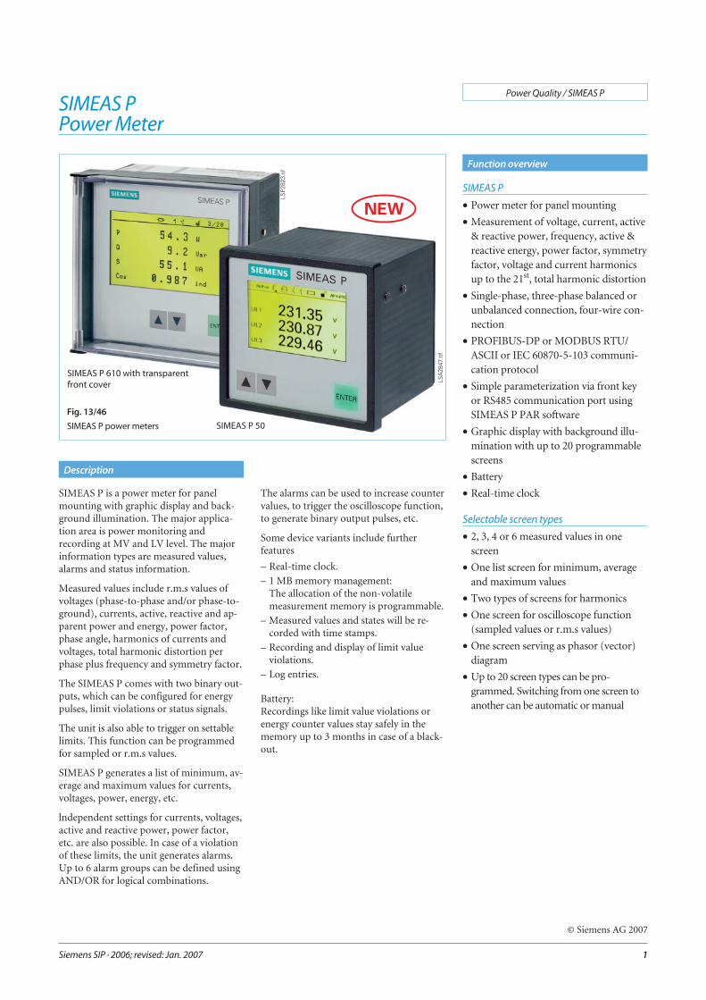
• Power meter for panel mounting
• Measurement of voltage, current, active& reactive power, frequency, active &reactive energy, power factor, symmetryfactor, voltage and current harmonicsup to the 21st, total harmonic distortion
• Single-phase, three-phase balanced orunbalanced connection, four-wire con-nection
• PROFIBUS-DP or MODBUS RTU/ASCII or IEC 60870-5-103 communi-cation protocol
• Simple parameterization via front keyor RS485 communication port usingSIMEAS P PAR software
• Graphic display with background illu-mination with up to 20 programmablescreens
• Battery
• Real-time clock
Selectable screen types
• 2, 3, 4 or 6 measured values in onescreen
• One list screen for minimum, averageand maximum values
• Two types of screens for harmonics
• One screen for oscilloscope function(sampled values or r.m.s values)
• One screen serving as phasor (vector)diagram
• Up to 20 screen types can be pro-grammed. Switching from one screen toanother can be automatic or manual
SIMEAS PPower Meter
SIMEAS P is a power meter for panelmounting with graphic display and back-ground illumination. The major applica-tion area is power monitoring andrecording at MV and LV level. The majorinformation types are measured values,alarms and status information.
Measured values include r.m.s values ofvoltages (phase-to-phase and/or phase-to-ground), currents, active, reactive and ap-parent power and energy, power factor,phase angle, harmonics of currents andvoltages, total harmonic distortion perphase plus frequency and symmetry factor.
The SIMEAS P comes with two binary out-puts, which can be configured for energypulses, limit violations or status signals.
The unit is also able to trigger on settablelimits. This function can be programmedfor sampled or r.m.s values.
SIMEAS P generates a list of minimum, av-erage and maximum values for currents,voltages, power, energy, etc.
lndependent settings for currents, voltages,active and reactive power, power factor,etc. are also possible. In case of a violationof these limits, the unit generates alarms.Up to 6 alarm groups can be defined usingAND/OR for logical combinations.
The alarms can be used to increase countervalues, to trigger the oscilloscope function,to generate binary output pulses, etc.
Some device variants include furtherfeatures
– Real-time clock.
– 1 MB memory management:The allocation of the non-volatilemeasurement memory is programmable.
– Measured values and states will be re-corded with time stamps.
– Recording and display of limit valueviolations.
– Log entries.
Battery:Recordings like limit value violations orenergy counter values stay safely in thememory up to 3 months in case of a black-out.
LSP2
823.
tif
Fig. 13/46
SIMEAS P power meters SIMEAS P 50
LSA
2847
.tif
SIMEAS P 610 with transparentfront cover
© Siemens AG 2007
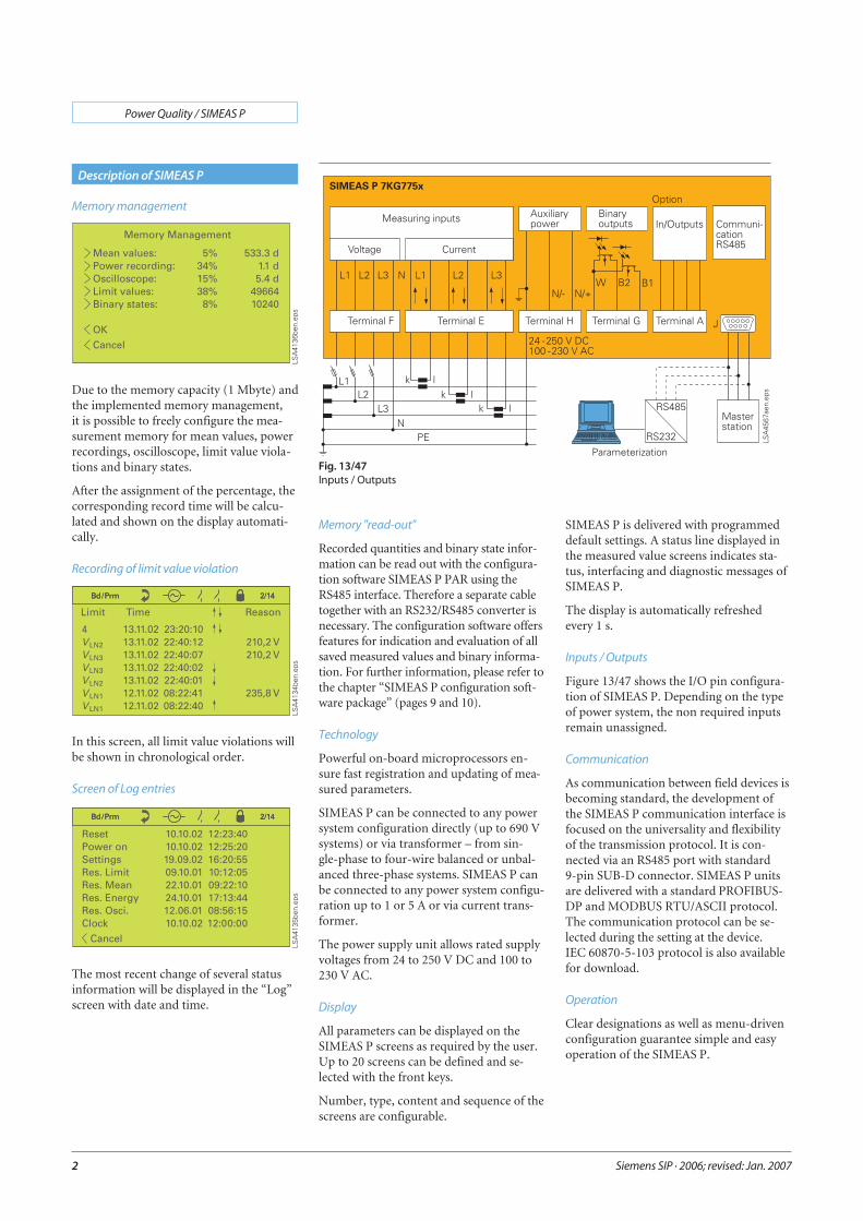
Memory management
Due to the memory capacity (1 Mbyte) andthe implemented memory management,it is possible to freely configure the mea-surement memory for mean values, powerrecordings, oscilloscope, limit value viola-tions and binary states.
After the assignment of the percentage, thecorresponding record time will be calcu-lated and shown on the display automati-cally.
Recording of limit value violation
In this screen, all limit value violations willbe shown in chronological order.
Screen of Log entries
The most recent change of several statusinformation will be displayed in the “Log”screen with date and time.
Siemens SIP · 2006; revised: Jan. 2007
Power Quality / SIMEAS P
2
Description of SIMEAS P
Fig. 13/47Inputs / Outputs
Memory "read-out"
Recorded quantities and binary state infor-mation can be read out with the configura-tion software SIMEAS P PAR using theRS485 interface. Therefore a separate cabletogether with an RS232/RS485 converter isnecessary. The configuration software offersfeatures for indication and evaluation of allsaved measured values and binary informa-tion. For further information, please refer tothe chapter “SIMEAS P configuration soft-ware package” (pages 9 and 10).
Technology
Powerful on-board microprocessors en-sure fast registration and updating of mea-sured parameters.
SIMEAS P can be connected to any powersystem configuration directly (up to 690 Vsystems) or via transformer – from sin-gle-phase to four-wire balanced or unbal-anced three-phase systems. SIMEAS P canbe connected to any power system configu-ration up to 1 or 5 A or via current trans-former.
The power supply unit allows rated supplyvoltages from 24 to 250 V DC and 100 to230 V AC.
Display
All parameters can be displayed on theSIMEAS P screens as required by the user.Up to 20 screens can be defined and se-lected with the front keys.
Number, type, content and sequence of thescreens are configurable.
SIMEAS P is delivered with programmeddefault settings. A status line displayed inthe measured value screens indicates sta-tus, interfacing and diagnostic messages ofSIMEAS P.
The display is automatically refreshedevery 1 s.
Inputs / Outputs
Figure 13/47 shows the I/O pin configura-tion of SIMEAS P. Depending on the typeof power system, the non required inputsremain unassigned.
Communication
As communication between field devices isbecoming standard, the development ofthe SIMEAS P communication interface isfocused on the universality and flexibilityof the transmission protocol. It is con-nected via an RS485 port with standard9-pin SUB-D connector. SIMEAS P unitsare delivered with a standard PROFIBUS-DP and MODBUS RTU/ASCII protocol.The communication protocol can be se-lected during the setting at the device.IEC 60870-5-103 protocol is also availablefor download.
Operation
Clear designations as well as menu-drivenconfiguration guarantee simple and easyoperation of the SIMEAS P.
Quality
Development and production of the deviceis carried out in accordance with ISO 9001,ensuring highest quality standard. Thatmeans high system reliability and productservice life. Further characteristics are theconstant high accuracy over years, CE des-ignation, EMC strength, as well as thecompliance with all relevant national andinternational standards.
Measuring functions
Measured input voltages and input cur-rents are sampled for calculation of thecorresponding r.m.s. values. All parametersderived from the measured values are cal-culated by a processor. They can be dis-played on the screens and/or transmittedvia the serial interface.
With the SIMEAS P it is also possible todefine several limit value groups with dif-ferent limit values for the measured pa-rameters. These can be combined withlogical elements, such as AND, OR. Viola-tions are counted and indicated on thescreen or made available at the binary out-puts. Triggering of the oscilloscope is pos-sible as well.
Security
Electrical isolation between inputs andoutputs, assured by high-voltage testing,guarantees maximum system security.
Configuration and calibration settings aretamper-proof by password protection.
Service
SIMEAS P require no maintenance and areeasy to service due to their modular design.
The units can easily be calibrated via thefront keys or with PC-based configurationsoftware.
Screens
20 screens can be selected on the display ofSIMEAS P with the front keys. lf requested,this routine can be executed automatically.
• Number, type and sequence of thescreens are freely configurable.
• 9 different types of screens can be se-lected:
− 2, 3, 4 or 6 measured-value screens
− 1 list screen for minimum, averageand maximum values
Siemens SIP · 2006; revised: Jan. 2007
Power Quality / SIMEAS P
3
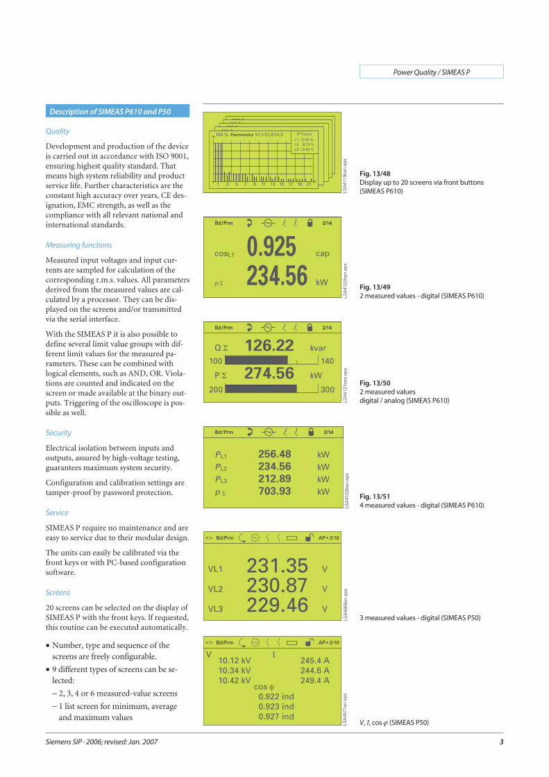
Description of SIMEAS P610 and P50
Fig. 13/48Display up to 20 screens via front buttons(SIMEAS P610)
Fig. 13/492 measured values - digital (SIMEAS P610)
Fig. 13/502 measured valuesdigital / analog (SIMEAS P610)
Fig. 13/514 measured values - digital (SIMEAS P610)
3 measured values - digital (SIMEAS P50)
V, I, cos ϕ (SIMEAS P50)
− 2 screens for harmonics
− 1 screen serving as oscilloscope
− 1 screen serving as phasor diagram
− U, I, cos ϕ-screen
Measured-value screens
• Number and content of the measured-value screens and the parameters can bedefined individually by the user.
• In addition, designations for the param-eters are available for selection inthe default setting:UL1, UL2, UL3, cos ϕ, or Va, Vb, Vc, PF,etc.
• To obtain a higher resolution, the lowerand upper measuring value can be set inthe bar chart display.
• Status and diagnostic messages of thedevice are indicated in the status linedisplayed on the measured-valuescreens.
• The screens are automatically updatedevery 1 s.
Screens
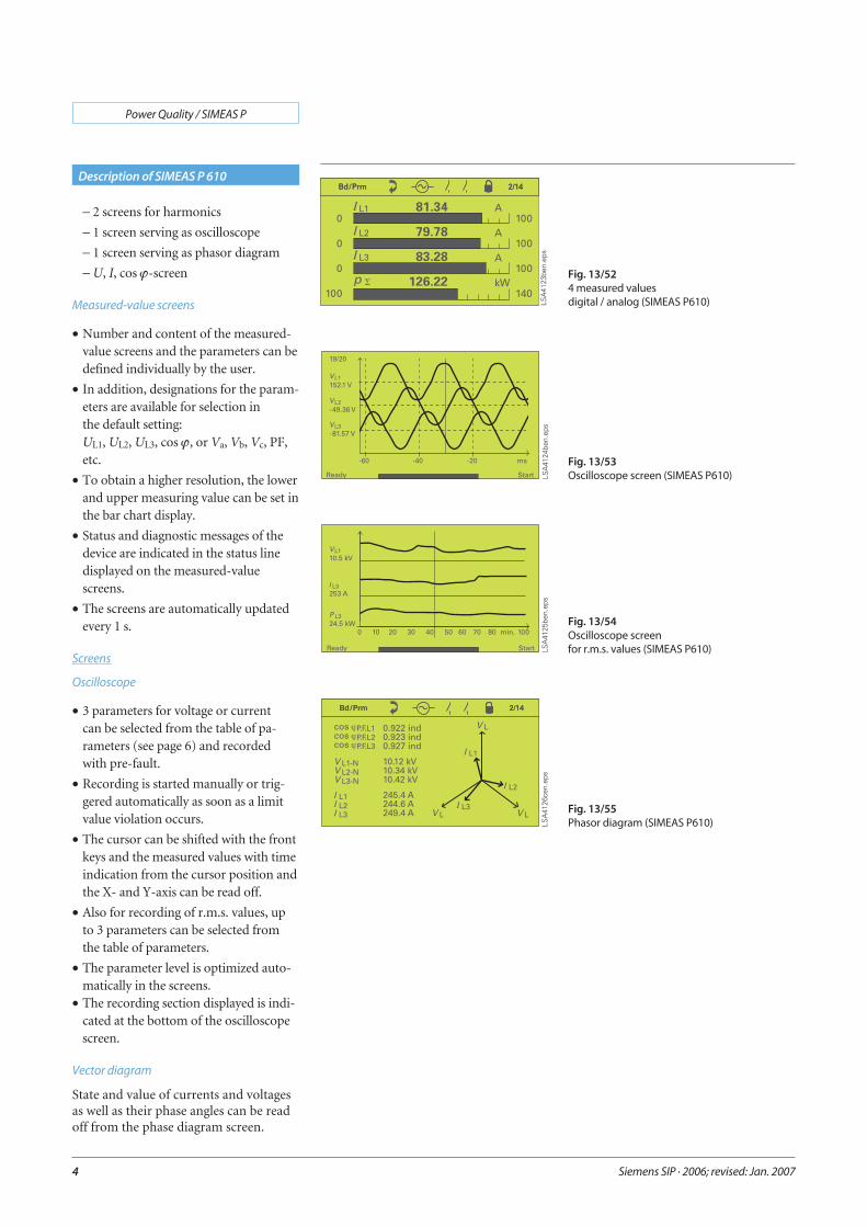
Oscilloscope
• 3 parameters for voltage or currentcan be selected from the table of pa-rameters (see page 6) and recordedwith pre-fault.
• Recording is started manually or trig-gered automatically as soon as a limitvalue violation occurs.
• The cursor can be shifted with the frontkeys and the measured values with timeindication from the cursor position andthe X- and Y-axis can be read off.
• Also for recording of r.m.s. values, upto 3 parameters can be selected fromthe table of parameters.
• The parameter level is optimized auto-matically in the screens.
• The recording section displayed is indi-cated at the bottom of the oscilloscopescreen.
Vector diagram
State and value of currents and voltagesas well as their phase angles can be readoff from the phase diagram screen.
Siemens SIP · 2006; revised: Jan. 2007
Power Quality / SIMEAS P
4
Description of SIMEAS P 610
Fig. 13/524 measured valuesdigital / analog (SIMEAS P610)
Fig. 13/53Oscilloscope screen (SIMEAS P610)
Fig. 13/54Oscilloscope screenfor r.m.s. values (SIMEAS P610)
Fig. 13/55Phasor diagram (SIMEAS P610)
Screens
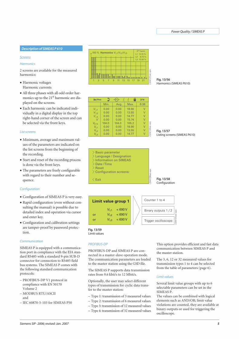
Harmonics
2 screens are available for the measuredharmonics:
• Harmonic voltagesHarmonic currents
• All three phases with all odd order har-monics up to the 21st harmonic are dis-played on the screens.
• Each harmonic can be indicated indi-vidually in a digital display in the topright-hand corner of the screen and canbe selected via the front keys.
List screens
• Minimum, average and maximum val-ues of the parameters are indicated onthe list screens from the beginning ofthe recording.
• Start and reset of the recording processis done via the front keys.
• The parameters are freely configurablewith regard to their number and se-quence.
Configuration
• Configuration of SIMEAS P is very easy.
• Rapid configuration (even without con-sulting the manual) is possible due todetailed index and operation via cursorand enter key.
• Configuration and calibration settingsare tamper-proof by password protec-tion.
Communication
SIMEAS P is equipped with a communica-tion port in compliance with the EIA stan-dard RS485 with a standard 9-pin SUB-Dconnector for connection to RS485 fieldbus systems. The SIMEAS P comes withthe following standard communicationprotocols:
– PROFIBUS-DP V1 protocol incompliance with EN 50170Volume 2
– MODBUS RTU/ASCIIand
– IEC 60870-5-103 for SIMEAS P50
PROFIBUS-DP
PROFIBUS-DP and SIMEAS P are con-nected in a master-slave operation mode.The communication parameters are loadedto the master station using the GSD file.
The SIMEAS P supports data transmissionrates from 9.6 kbit/s to 12 Mbit/s.
Optionally, the user may select differenttypes of transmission for cyclic data trans-fer to the master station:
– Type 1: transmission of 3 measured values
– Type 2: transmission of 6 measured values
– Type 3: transmission of 12 measured values
– Type 4: transmission of 32 measured values
This option provides efficient and fast datacommunication between SIMEAS P andthe master station.
The 3, 6, 12 or 32 measured values fortransmission types 1 to 4 can be selectedfrom the table of parameters (page 6).
Limit values
Several limit value groups with up to 6selectable parameters can be set in theSIMEAS P.The values can be combined with logicalelements such as AND/OR; limit valueviolations are counted, they are available atbinary outputs or used for triggering theoscilloscope.
Siemens SIP · 2006; revised: Jan. 2007
Power Quality / SIMEAS P
5
Description of SIMEAS P 610
Fig. 13/56Harmonics (SIMEAS P610)
Fig. 13/57Listing screens (SIMEAS P610)
Fig. 13/58Configuration
Fig. 13/59Limit values
Binary outputs
The standard SIMEAS P comes with2 binary outputs which are free for config-uration with:
– Status signals
– Energy values from the table of parame-ters
– Limit value violations
Siemens SIP · 2006; revised: Jan. 2007
Power Quality / SIMEAS P
6
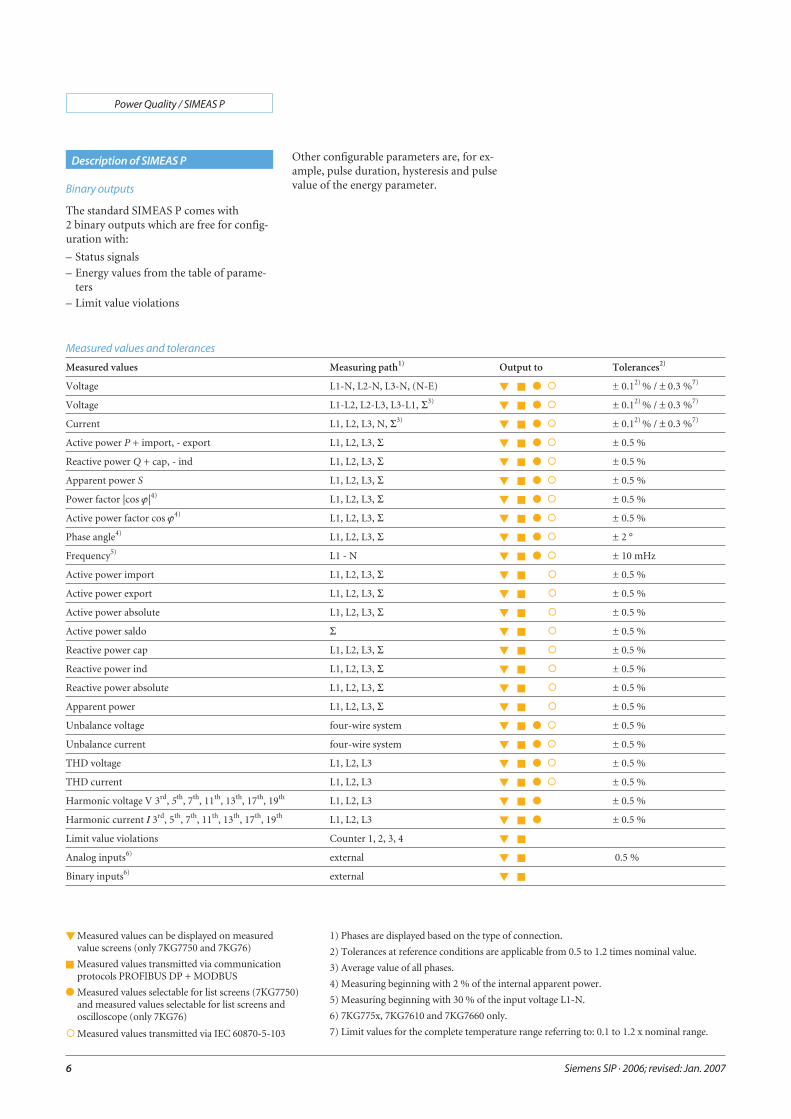
Description of SIMEAS P
Measured values Measuring path1) Output to Tolerances2)
Voltage L1-N, L2-N, L3-N, (N-E) � � � � ± 0.12) % / ± 0.3 %7)
Voltage L1-L2, L2-L3, L3-L1, Σ3) � � � � ± 0.12) % / ± 0.3 %7)
Current L1, L2, L3, N, Σ3) � � � � ± 0.12) % / ± 0.3 %7)
Active power P + import, - export L1, L2, L3, Σ � � � � ± 0.5 %
Reactive power Q + cap, - ind L1, L2, L3, Σ � � � � ± 0.5 %
Apparent power S L1, L2, L3, Σ � � � � ± 0.5 %
Power factor |cos ϕ|4) L1, L2, L3, Σ � � � � ± 0.5 %
Active power factor cos ϕ4) L1, L2, L3, Σ � � � � ± 0.5 %
Phase angle4) L1, L2, L3, Σ � � � � ± 2 °
Frequency5) L1 - N � � � � ± 10 mHz
Active power import L1, L2, L3, Σ � � � ± 0.5 %
Active power export L1, L2, L3, Σ � � � ± 0.5 %
Active power absolute L1, L2, L3, Σ � � � ± 0.5 %
Active power saldo Σ � � � ± 0.5 %
Reactive power cap L1, L2, L3, Σ � � � ± 0.5 %
Reactive power ind L1, L2, L3, Σ � � � ± 0.5 %
Reactive power absolute L1, L2, L3, Σ � � � ± 0.5 %
Apparent power L1, L2, L3, Σ � � � ± 0.5 %
Unbalance voltage four-wire system � � � � ± 0.5 %
Unbalance current four-wire system � � � � ± 0.5 %
THD voltage L1, L2, L3 � � � � ± 0.5 %
THD current L1, L2, L3 � � � � ± 0.5 %
Harmonic voltage V 3rd, 5th, 7th, 11th, 13th, 17th, 19th L1, L2, L3 � � � ± 0.5 %
Harmonic current I 3rd, 5th, 7th, 11th, 13th, 17th, 19th L1, L2, L3 � � � ± 0.5 %
Limit value violations Counter 1, 2, 3, 4 � �
Analog inputs6) external � � 0.5 %
Binary inputs6) external � �
Measured values and tolerances
� Measured values can be displayed on measuredvalue screens (only 7KG7750 and 7KG76)
� Measured values transmitted via communicationprotocols PROFIBUS DP + MODBUS
� Measured values selectable for list screens (7KG7750)and measured values selectable for list screens andoscilloscope (only 7KG76)
�Measured values transmitted via IEC 60870-5-103
1) Phases are displayed based on the type of connection.
2) Tolerances at reference conditions are applicable from 0.5 to 1.2 times nominal value.
3) Average value of all phases.
4) Measuring beginning with 2 % of the internal apparent power.
5) Measuring beginning with 30 % of the input voltage L1-N.
6) 7KG775x, 7KG7610 and 7KG7660 only.
7) Limit values for the complete temperature range referring to: 0.1 to 1.2 x nominal range.
Other configurable parameters are, for ex-ample, pulse duration, hysteresis and pulsevalue of the energy parameter.
The SIMEAS P can be ordered for snap-onmounting on a 35 mm DIN rail.For carrying out the setting of the devicethe configuration software is necessary.
Siemens SIP · 2006; revised: Jan. 2007
Power Quality / SIMEAS P
7
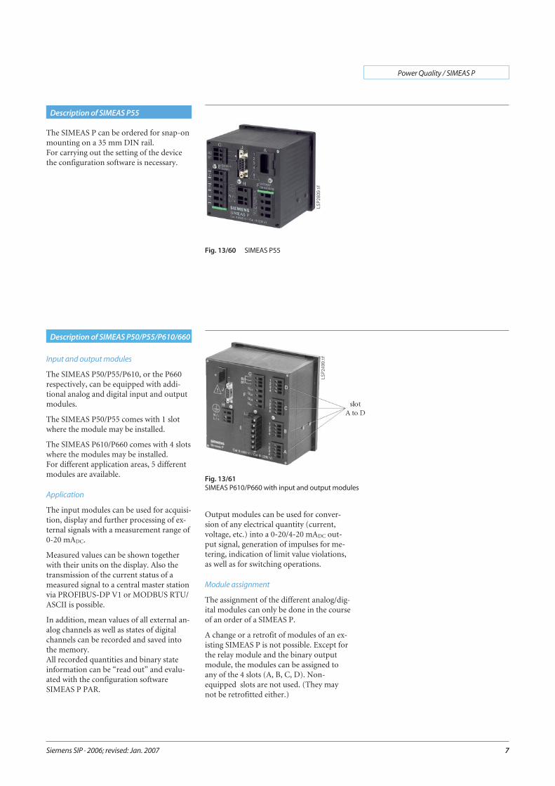
Description of SIMEAS P55
Fig. 13/61SIMEAS P610/P660 with input and output modules
LSP2
499.
tif
Description of SIMEAS P50/P55/P610/660
Input and output modules
The SIMEAS P50/P55/P610, or the P660respectively, can be equipped with addi-tional analog and digital input and outputmodules.
The SIMEAS P50/P55 comes with 1 slotwhere the module may be installed.
The SIMEAS P610/P660 comes with 4 slotswhere the modules may be installed.For different application areas, 5 differentmodules are available.
Application
The input modules can be used for acquisi-tion, display and further processing of ex-ternal signals with a measurement range of0-20 mADC.
Measured values can be shown togetherwith their units on the display. Also thetransmission of the current status of ameasured signal to a central master stationvia PROFIBUS-DP V1 or MODBUS RTU/ASCII is possible.
In addition, mean values of all external an-alog channels as well as states of digitalchannels can be recorded and saved intothe memory.All recorded quantities and binary stateinformation can be “read out” and evalu-ated with the configuration softwareSIMEAS P PAR.
Output modules can be used for conver-sion of any electrical quantity (current,voltage, etc.) into a 0-20/4-20 mADC out-put signal, generation of impulses for me-tering, indication of limit value violations,as well as for switching operations.
Module assignment
The assignment of the different analog/dig-ital modules can only be done in the courseof an order of a SIMEAS P.
A change or a retrofit of modules of an ex-isting SIMEAS P is not possible. Except forthe relay module and the binary outputmodule, the modules can be assigned toany of the 4 slots (A, B, C, D). Non-equipped slots are not used. (They maynot be retrofitted either.)
Fig. 13/60 SIMEAS P55
LSP2
809.
tif
Siemens SIP · 2006; revised: Jan. 2007
Power Quality / SIMEAS P
8
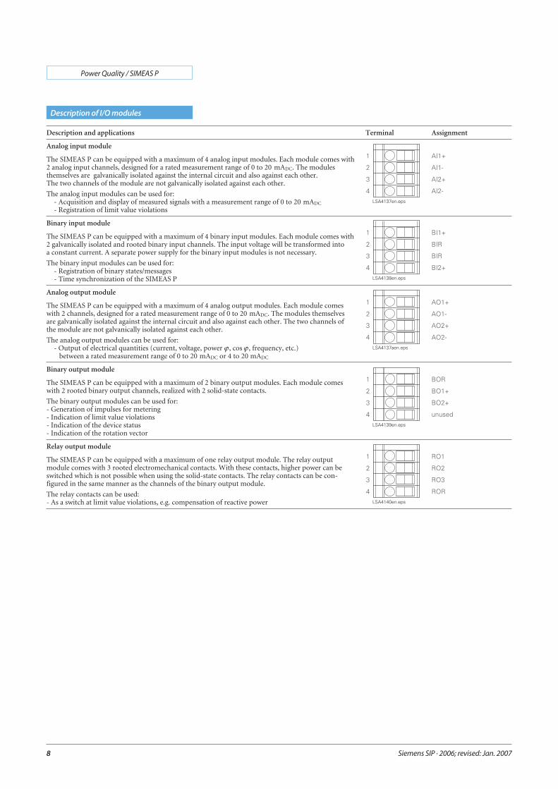
Description of I/O modules
Description and applications Terminal Assignment
Analog input module
The SIMEAS P can be equipped with a maximum of 4 analog input modules. Each module comes with2 analog input channels, designed for a rated measurement range of 0 to 20 mADC. The modulesthemselves are galvanically isolated against the internal circuit and also against each other.The two channels of the module are not galvanically isolated against each other.
The analog input modules can be used for:- Acquisition and display of measured signals with a measurement range of 0 to 20 mADC
- Registration of limit value violations
Binary input module
The SIMEAS P can be equipped with a maximum of 4 binary input modules. Each module comes with2 galvanically isolated and rooted binary input channels. The input voltage will be transformed intoa constant current. A separate power supply for the binary input modules is not necessary.
The binary input modules can be used for:- Registration of binary states/messages- Time synchronization of the SIMEAS P
Analog output module
The SIMEAS P can be equipped with a maximum of 4 analog output modules. Each module comeswith 2 channels, designed for a rated measurement range of 0 to 20 mADC. The modules themselvesare galvanically isolated against the internal circuit and also against each other. The two channels ofthe module are not galvanically isolated against each other.
The analog output modules can be used for:- Output of electrical quantities (current, voltage, power ϕ, cos ϕ, frequency, etc.)
between a rated measurement range of 0 to 20 mADC or 4 to 20 mADC
Binary output module
The SIMEAS P can be equipped with a maximum of 2 binary output modules. Each module comeswith 2 rooted binary output channels, realized with 2 solid-state contacts.
The binary output modules can be used for:- Generation of impulses for metering- Indication of limit value violations- Indication of the device status- Indication of the rotation vector
Relay output module
The SIMEAS P can be equipped with a maximum of one relay output module. The relay outputmodule comes with 3 rooted electromechanical contacts. With these contacts, higher power can beswitched which is not possible when using the solid-state contacts. The relay contacts can be con-figured in the same manner as the channels of the binary output module.
The relay contacts can be used:- As a switch at limit value violations, e.g. compensation of reactive power
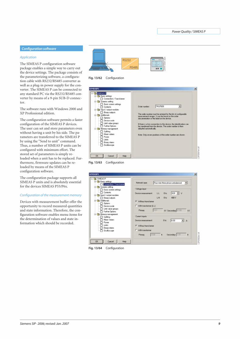
Application
The SIMEAS P configuration softwarepackage enables a simple way to carry outthe device settings. The package consists ofthe parameterizing software, a configura-tion cable with RS232/RS485 converter aswell as a plug-in power supply for the con-verter. The SIMEAS P can be connected toany standard PC via the RS232/RS485 con-verter by means of a 9-pin SUB-D connec-tor.
The software runs with Windows 2000 andXP Professional edition.
The configuration software permits a fasterconfiguration of the SIMEAS P devices.The user can set and store parameters evenwithout having a unit by his side. The pa-rameters are transferred to the SIMEAS Pby using the “Send to unit” command.Thus, a number of SIMEAS P units can beconfigured with minimum effort. Thestored set of parameters is simply re-loaded when a unit has to be replaced. Fur-thermore, firmware updates can be re-loaded by means of the SIMEAS Pconfiguration software.
The configuration package supports allSIMEAS P units and is absolutely essentialfor the devices SIMEAS P55/P6x.
Configuration of the measurement memory
Devices with measurement buffer offer theopportunity to record measured quantitiesand state information. Therefore, the con-figuration software enables menu items forthe determination of values and state in-formation which should be recorded.
Siemens SIP · 2006; revised: Jan. 2007
Power Quality / SIMEAS P
9
Configuration software
Fig. 13/62 Configuration
Fig. 13/63 Configuration
Fig. 13/64 Configuration
LSP2
501e
n.tif
LSP2
502e
n.tif

Memory read-out
Separate functions integrated in the config-uration software, enable a read-out of thefollowing information:
– Mean values
– Mean values of power
– Oscilloscope recordings
– State information of binary channels
– Limit value violations
– Log entries
Display and evaluation
All values and information read out via thesoftware are shown automatically in tabu-lar and graphical form together with thetime stamp on the screen.
The context menu offers some functions(masking of signals, copy, zoom, measur-ing functions) for easy analysis of mea-sured values and state information.The following measured values can beshown in graphical form:
– Mean values of voltage and current
– Mean values of power
– Oscilloscope recordings
– State information of binary channels
The following information are shown intabular form:
– Limit value violations
– Log entries
Export function
The software also enables a function forthe export of transmitted values and stateinformation into an ASCII-file. ThisASCII-file can be used in other applica-tions, e.g. MS-Excel. Oscilloscope record-ings can be exported into COMTRADEformatted files.
Siemens SIP · 2006; revised: Jan. 2007
Power Quality / SIMEAS P
10
Configuration software
Fig. 13/65 Configuration of the measurement memory
Fig. 13/66 Display and evaluation
Fig. 13/67 Display and evaluation
LSP2
492e
n.tif
LSP2
504e
n.tif
LSP2
503e
n.tif
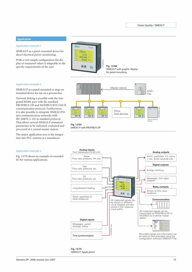
Application example 1
SIMEAS P as a panel-mounted device fordirect electrical power monitoring.
With a very simple configuration the dis-play of measured values is adaptable to thespecific requirements of the user.
Application example 2
SIMEAS P as a panel-mounted or snap-onmounted device for use on a process bus.
Network linking is possible with the inte-grated RS485 port with the standardPROFIBUS-DP and MODBUS RTU/ASCIIcommunication protocol. Furthermore,it is also possible to integrate SIMEAS P50into communication networks withIEC 60870-5-103 as standard protocol.That allows several SIMEAS P measuredparameters to be indicated, evaluated andprocessed at a central master station.
The major application area is the integra-tion into PLC systems as a transducer.
Siemens SIP · 2006; revised: Jan. 2007
Power Quality / SIMEAS P
11
Fig. 13/70SIMEAS P: Applications
Application
Fig. 13/69SIMEAS P with PROFIBUS-DP
Fig. 13/68SIMEAS P with graphic displayfor panel mounting
Application example 3
Fig. 13/70 shows an example of extendedIO for various applications.
LSP2
805.
tif
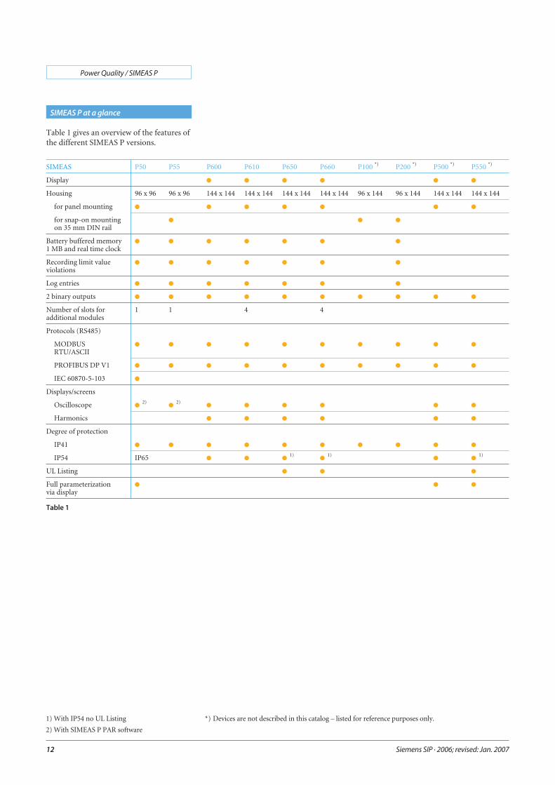
Table 1 gives an overview of the features ofthe different SIMEAS P versions.
Siemens SIP · 2006; revised: Jan. 2007
Power Quality / SIMEAS P
12
SIMEAS P at a glance
SIMEAS P50 P55 P600 P610 P650 P660 P100 *) P200 *) P500 *) P550 *)
Display � � � � � �
Housing 96 x 96 96 x 96 144 x 144 144 x 144 144 x 144 144 x 144 96 x 144 96 x 144 144 x 144 144 x 144
for panel mounting � � � � � � �
for snap-on mountingon 35 mm DIN rail
� � �
Battery buffered memory1 MB and real time clock
� � � � � � �
Recording limit valueviolations
� � � � � � �
Log entries � � � � � � �
2 binary outputs � � � � � � � � � �
Number of slots foradditional modules
1 1 4 4
Protocols (RS485)
MODBUSRTU/ASCII
� � � � � � � � � �
PROFIBUS DP V1 � � � � � � � � � �
IEC 60870-5-103 �
Displays/screens
Oscilloscope �2)
�2)
� � � � � �
Harmonics � � � � � �
Degree of protection
IP41 � � � � � � � � � �
IP54 IP65 � � �1)
�1)
� �1)
UL Listing � � �
Full parameterizationvia display
� � �
Table 1
1) With IP54 no UL Listing
2) With SIMEAS P PAR software
*) Devices are not described in this catalog – listed for reference purposes only.
Siemens SIP · 2006; revised: Jan. 2007
Power Quality / SIMEAS P
13
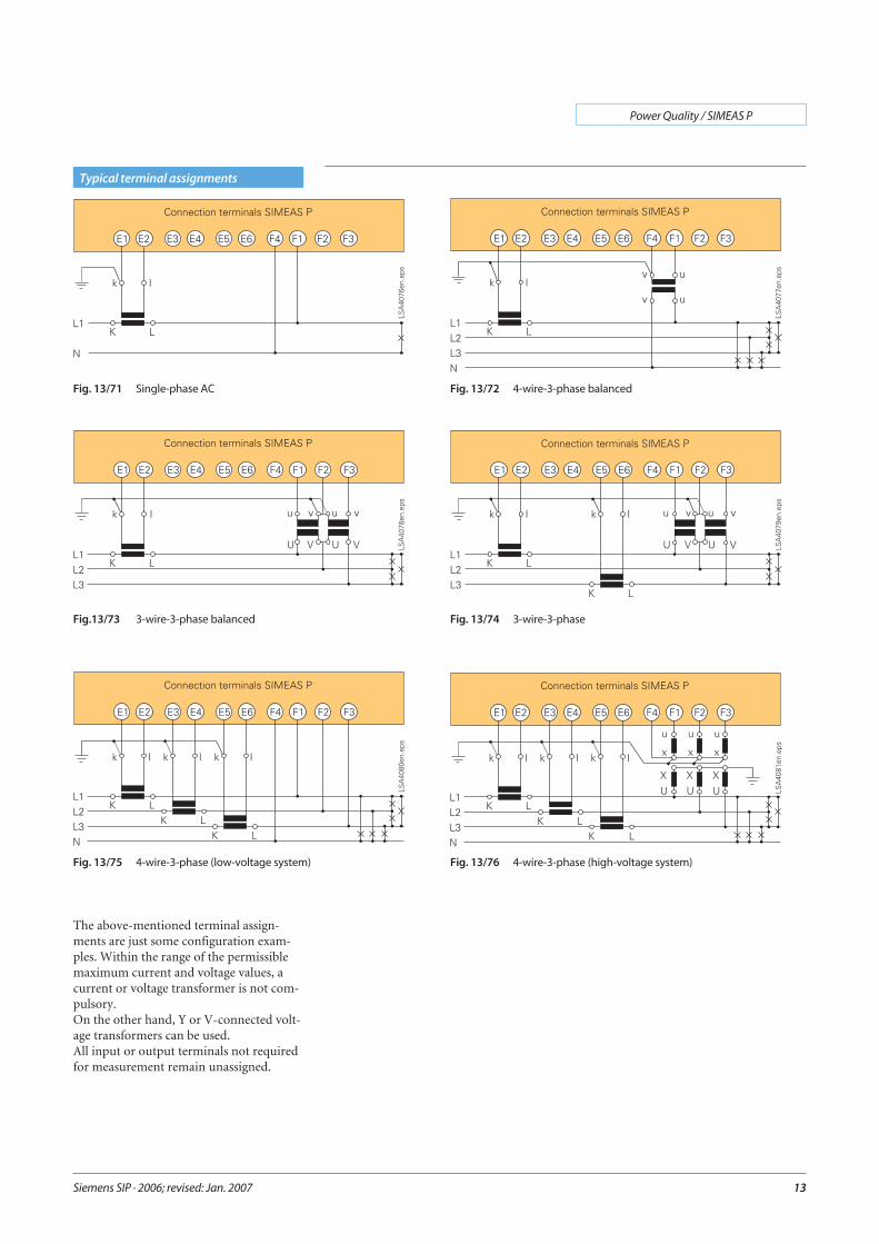
Typical terminal assignments
Fig. 13/71 Single-phase AC Fig. 13/72 4-wire-3-phase balanced
Fig.13/73 3-wire-3-phase balanced Fig. 13/74 3-wire-3-phase
Fig. 13/75 4-wire-3-phase (low-voltage system) Fig. 13/76 4-wire-3-phase (high-voltage system)
The above-mentioned terminal assign-ments are just some configuration exam-ples. Within the range of the permissiblemaximum current and voltage values, acurrent or voltage transformer is not com-pulsory.On the other hand, Y or V-connected volt-age transformers can be used.All input or output terminals not requiredfor measurement remain unassigned.
Siemens SIP · 2006; revised: Jan. 2007
Power Quality / SIMEAS P
14
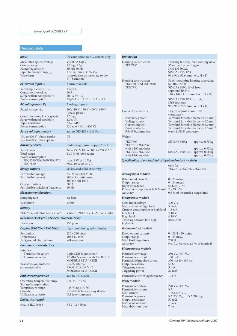
Technical data
Unit design
Housing construction7KG7755
Housing for snap-on mounting on a35 mm rail according toDIN EN 50022.SIMEAS P55: IP 4194 x 94 x 93.6 mm (W x H x D)
Housing construction7KG7500 and 7KG7600,7KG7750
Panel-mounting housing accordingto DIN 43700.SIMEAS P600: IP 41 front(optional IP 54)144 x 144 x115.3 mm (W x H x D)
SIMEAS P50: IP 41 (front),IP65 (option)96 x 96 x 76.5 mm (W x H x D)
Connector elements
Auxiliary powerVoltage inputsCurrent inputsBinary outputsRS485 bus interface
Degree of protection IP 20(terminals)Terminal for cable diameter 2.5 mm2
Terminal for cable diameter 2.5 mm2
Terminal for cable diameter 4.0 mm2
Terminal for cable diameter 2.5 mm2
9-pin SUB-D connector
Weight
7KG760/7KG7610/7KG7660with 4 I/O modules7KG7750/7KG7755with 1 I/O module
SIMEAS P600: approx. 0.75 kg
approx. 0.95 kgSIMEAS P50/P55: approx. 0.60 kg
approx. 0.65 kg
Specification of analog/digital input and output modules
only for7KG7610/7KG7660/7KG775x
Analog input module
Rated input currentOutput rangeInput impedancePower consumption at IN 0 24 mAAccuracy
0 - 20 mADC
0 - 24 mADC
50 Ω ± 0.1 %2 x 29 mW0.5 % of measuring range limit
Binary input module
Max. input voltageMax. current at high levelCurrent consumption at high levelLow levelHigh levelTime lag between low-high,high-low
300 VDC
53 mA1.8 mA≤ 10 V≤ 19 Vmax. 3 ms
Analog output module
Rated output currentOutput rangeMax. load impedanceAccuracy
0 - 20/4 - 20 mADC
0 - 24 mADC
250 Ωtyp. 0.2 %; max. 1.1 % of nominal
Binary output module
Permissible voltagePermissible currentPermissible impulse currentOutput resistanceTriggering currentTriggering power
230 VAC/250 VDC
100 mA300 mA for 100 ms50 Ω5 mA25 mW
Permissible switching frequency 10 Hz
Relay module
Permissible voltagePermissible currentMin. currentPermissible powerOutput resistanceMax. reaction timeMax. drop-out time
270 VAC/120 VDC
5 A1 mA at 5 VDC
5 A/250 VAC or 5 A/30 VDC
50 mΩ10 ms7 ms
Input for connection to AC systems only
Max. rated system voltageControl rangeRated frequency fEN
Input frequency range fE
Waveform
Y 400 / Δ 690 V1.2 VEN / IEN
50 Hz; 60 Hz± 5 Hz, min > 30 % VEN
sinusoidal or distorted up to the21st harmonic
AC current input IE 3 current inputs
Rated input current IEN
Continuous overloadSurge withstand capabilityPower consumption
1 A; 5 A10 A100 A for 1 s83 μVA at 1 A; 2.1 mVA at 5 A
AC voltage input VE 3 voltage inputs
Rated voltage VEN
Continuous overload capacitySurge withstand capabilityInput resistancePower consumption
100/110 V; 190 V; 400 V; 690 V(phase-phase)1.5 VEN
2.0 x VEN
2.663 MΩ120 mW (VLE = 400 V)
Surge voltage category acc. to DIN EN 61010 Part 1
VEN to 400 V (phase-earth)VEN to 690 V (phase-phase)
IIIII
Auxiliary power multi-range power supply AC / DC
Rated rangeTotal rangePower consumption
7KG7550/7KG7650/7KG7757KG7660
24 to 250 V DC or 100 to 230 V AC± 20 % of rated range
max. 4 W or 10 VAmax. 10 W or 25 VA
Binary outputs via isolated solid-state relay
Permissible voltagePermissible current
Output resistancePermissible switching frequency
230 V AC; 400 V DC100 mA continuous300 mA for 100 s50 Ω10 Hz
Measurement functions
Sampling rate 3.6 kHz
Resolution 12 bit
Battery
7KG72xx, 7KG76xx and 7KG77 Varta CR2032, 3 V, Li-Mn or similar
Real-time clock (7KG72xx/7KG76xx/7KG77xx)
Deviation 150 ppm
Display (7KG75xx / 7KG76xx) high-resolution graphic display
ResolutionDimensionsBackground illumination
120 x 240 pixel103 x 60 mmyellow-green
Communication interface
InterfaceTermination systemTransmission rate
Transmission protocolsparameterizable
9-pin SUB D connector12 Mbit/sec max. with PROFIBUSMODBUS RTU / ASCIIRS485 internalPROFIBUS-DP V1.0MODBUS RTU / ASCII
Ambient temperature acc. to IEC 60688
Operating temperature rangeStorage/transportationTemperature rangeClimaticUtilization category
0 °C to + 55 °C
- 25 °C to + 70 °CEN 60721-3-3 rare easy dewfallIR2 (environment)
Dielectric strength
Acc. to IEC 60688 5 kV 1.2 / 50 μs
Siemens SIP · 2006; revised: Jan. 2007
Power Quality / SIMEAS P
15
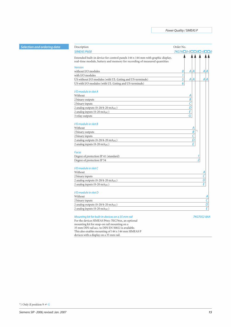
Selection and ordering data Description Order No.
SIMEAS P600 7KG76�0-0��0�-0��0
Extended built-in device for control panels 144 x 144 mm with graphic display,real-time module, battery and memory for recording of measured quantities
Versionwithout I/O modules 0 A A A Awith I/O modules 1US without I/O modules (with UL-Listing and US-terminals) 5 A A A AUS with I/O modules (with UL-Listing and US-terminals) 6
I/O module in slot AWithout A2 binary outputs B2 binary inputs C2 analog outputs (0-20/4-20 mADC) D2 analog inputs (0-20 mADC) E3 relay outputs G
I/O module in slot BWithout A2 binary outputs B *)
2 binary inputs C2 analog outputs (0-20/4-20 mADC) D2 analog inputs (0-20 mADC) E
FaciaDegree of protection IP 41 (standard) 1Degree of protection IP 54 2
I/O module in slot CWithout A2 binary inputs C2 analog outputs (0-20/4-20 mADC) D2 analog inputs (0-20 mADC) E
I/O module in slot DWithout A2 binary inputs C2 analog outputs (0-20/4-20 mADC) D2 analog inputs (0-20 mADC) E
Mounting kit for built-in devices on a 35 mm rail 7KG7052-8AAFor the devices SIMEAS P6xx-7KG76xx, an optionalmounting kit for snap-on rail mounting on a35 mm DIN rail acc. to DIN EN 50022 is available.This also enables mounting of 144 x 144 mm SIMEAS Pdevices with a display on a 35 mm rail.
*) Only if position 9 � G
Siemens SIP · 2006; revised: Jan. 2007
Power Quality / SIMEAS P
16
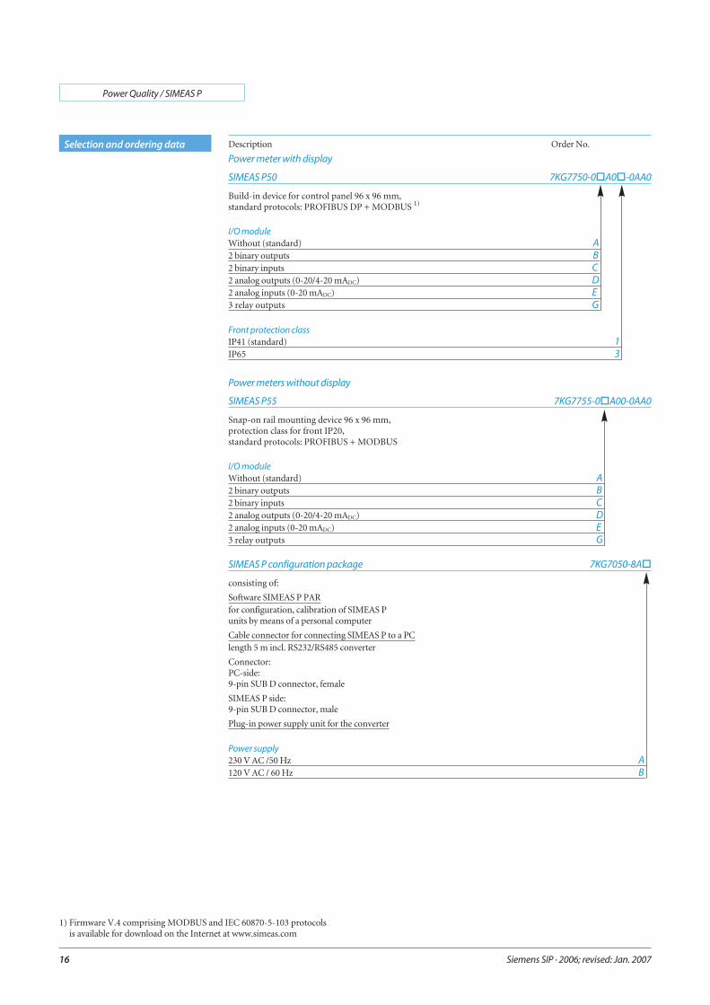
Selection and ordering data Description Order No.
Power meter with display
SIMEAS P50 7KG7750-0�A0�-0AA0
Build-in device for control panel 96 x 96 mm,standard protocols: PROFIBUS DP + MODBUS 1)
I/O moduleWithout (standard) A2 binary outputs B2 binary inputs C2 analog outputs (0-20/4-20 mADC) D2 analog inputs (0-20 mADC) E3 relay outputs G
Front protection classIP41 (standard) 1IP65 3
Power meters without display
SIMEAS P55 7KG7755-0�A00-0AA0
Snap-on rail mounting device 96 x 96 mm,protection class for front IP20,standard protocols: PROFIBUS + MODBUS
I/O moduleWithout (standard) A2 binary outputs B2 binary inputs C2 analog outputs (0-20/4-20 mADC) D2 analog inputs (0-20 mADC) E3 relay outputs G
SIMEAS P configuration package 7KG7050-8A�
consisting of:
Software SIMEAS P PARfor configuration, calibration of SIMEAS Punits by means of a personal computer
Cable connector for connecting SIMEAS P to a PClength 5 m incl. RS232/RS485 converter
Connector:PC-side:9-pin SUB D connector, female
SIMEAS P side:9-pin SUB D connector, male
Plug-in power supply unit for the converter
Power supply230 V AC /50 Hz A120 V AC / 60 Hz B
1) Firmware V.4 comprising MODBUS and IEC 60870-5-103 protocolsis available for download on the Internet at www.simeas.com
Siemens SIP · 2006; revised: Jan. 2007
Power Quality / SIMEAS P
17
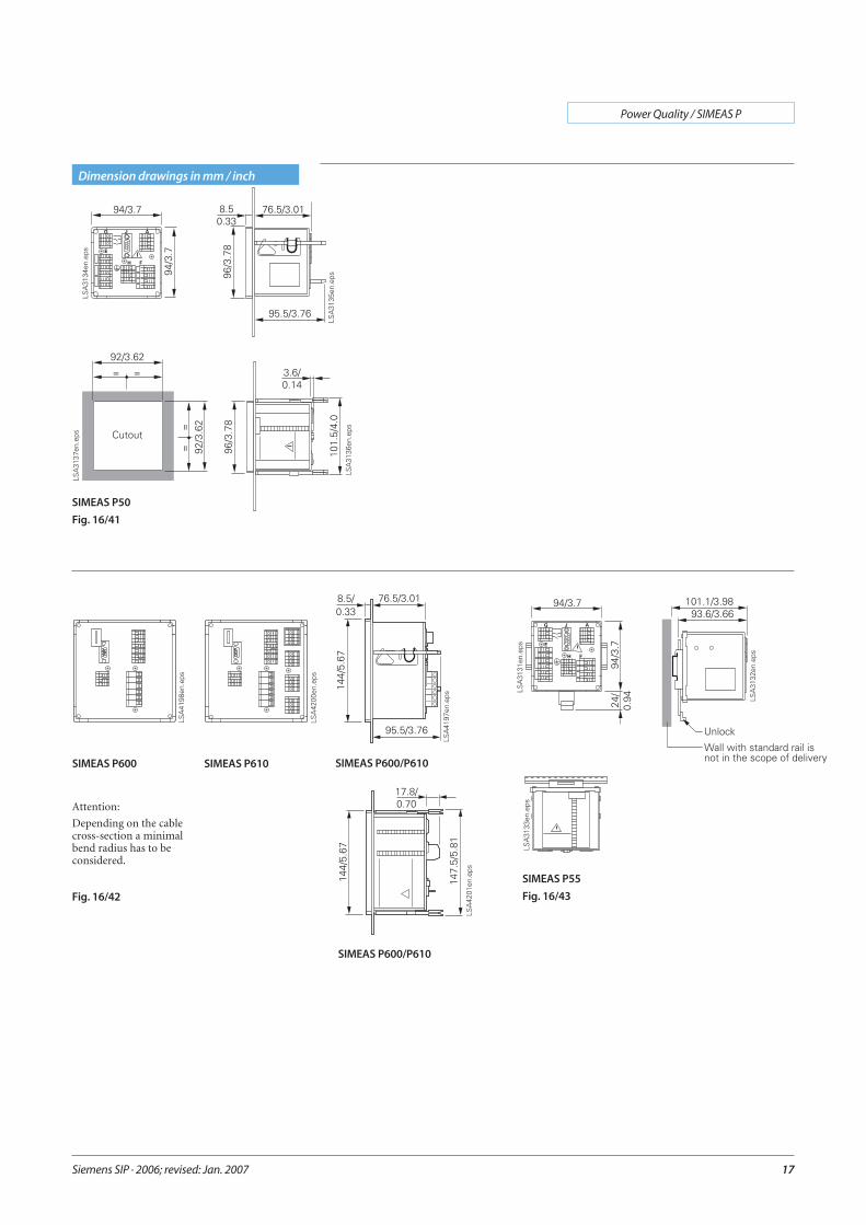
Dimension drawings in mm / inch
Fig. 16/42
SIMEAS P610
SIMEAS P600/P610
SIMEAS P600/P610
Attention:
Depending on the cablecross-section a minimalbend radius has to beconsidered.
SIMEAS P50
Fig. 16/41
SIMEAS P55
Fig. 16/43
SIMEAS P600
Siemens SIP · 2006; revised: Jan. 2007
Power Quality / SIMEAS P
18
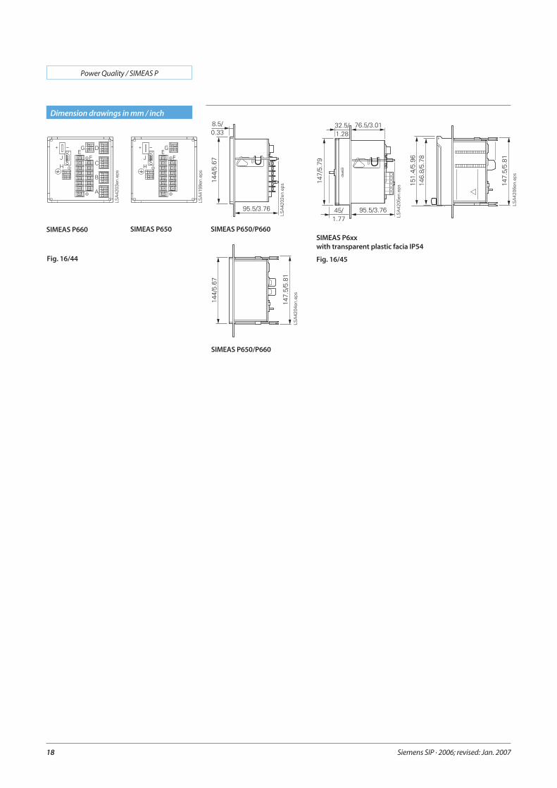
Dimension drawings in mm / inch
SIMEAS P6xxwith transparent plastic facia IP54
Fig. 16/45
SIMEAS P650 SIMEAS P650/P660
SIMEAS P650/P660
Fig. 16/44
SIMEAS P660
19
Power Quality / SIMEAS P
Siemens SIP · 2006; revised: Jan. 2007
Notes
If not stated otherwise onthe individual pages of thiscatalog, we reserve the rightto include modifications, espe-cially regarding the stated val-ues, dimensions and weights.
Drawings are not binding.
All product designations usedare trademarks or productnames of Siemens AG or othersuppliers.
If not stated otherwise, alldimensions in this catalog aregiven in mm.

20 Order No.: E50001-K4400-B101-A1-7600
Responsible for
Technical contents:Ralf HeisigSiemens AG, Dept. PTD EA 13Nuernberg
General editing:Claudia Kühn-SutionoSiemens AG, Dept. PTD CC MErlangen


If you have any questions aboutPower Transmission and Distribution,our Customer Support Center isavailable around the clock.Tel.: +49 180/524 70 00Fax: +49 180/524 24 71(Subject to charge: e.g. 12 ct/min)E-Mail: [email protected]/energy-support
Siemens AGPower Transmission and DistributionEnergy Automation DivisionPostfach 48 0690026 NuernbergDeutschland
www.siemens.com/simeaswww.siemens.com/energy-automation
Subject to change without noticeOrder No.: E50001-K4400-B101-A1-7600Printed in GermanyDispo 31900KG 01.07 3.0 20 En102310 6101/C6141
The information in this document contains general descriptions of the technical options available, which do not always have to be present in individual cases.The required features should therefore be specified in each individual case at the time of closing the contract.