Embed Size (px)
Citation preview
Solutions for power transmission
www.konaflex.fi
Power Jacks E-sarja

DESIGN WITH POWER
Head OfficeSouth Harbour RoadFraserburghAberdeenshireAB43 9BZScotland (UK)
FM 23810
2009 All rights reserved. PJSJB-E-EN-01
E-Series
Tel: +44 (0)1346 513131Fax: +44 (0) 1346 [email protected]
Designed and manufactured in Great Britain
Metric Machine Screw and Ball Screw Jacks
Power Jacks are an industry leader in the manufacture of qualityindustrial lifting, positioning,material handling and powertransmission equipment. The products are supplied globally tomost industry sectors including nuclear, water, oil & gas, chemical,defence, steel, aluminium, automotive, and others.
PRECISION SCREW JACKS . ELECTRIC LINEAR ACTUATORS .
PLANETARY ROLLER SCREWS . SPIRAL BEVEL GEARBOXES .

E-Series Metric Screw Jacks E-Series Metric Screw Jacks
www.powerjacks.com www.powerjacks.com2 15
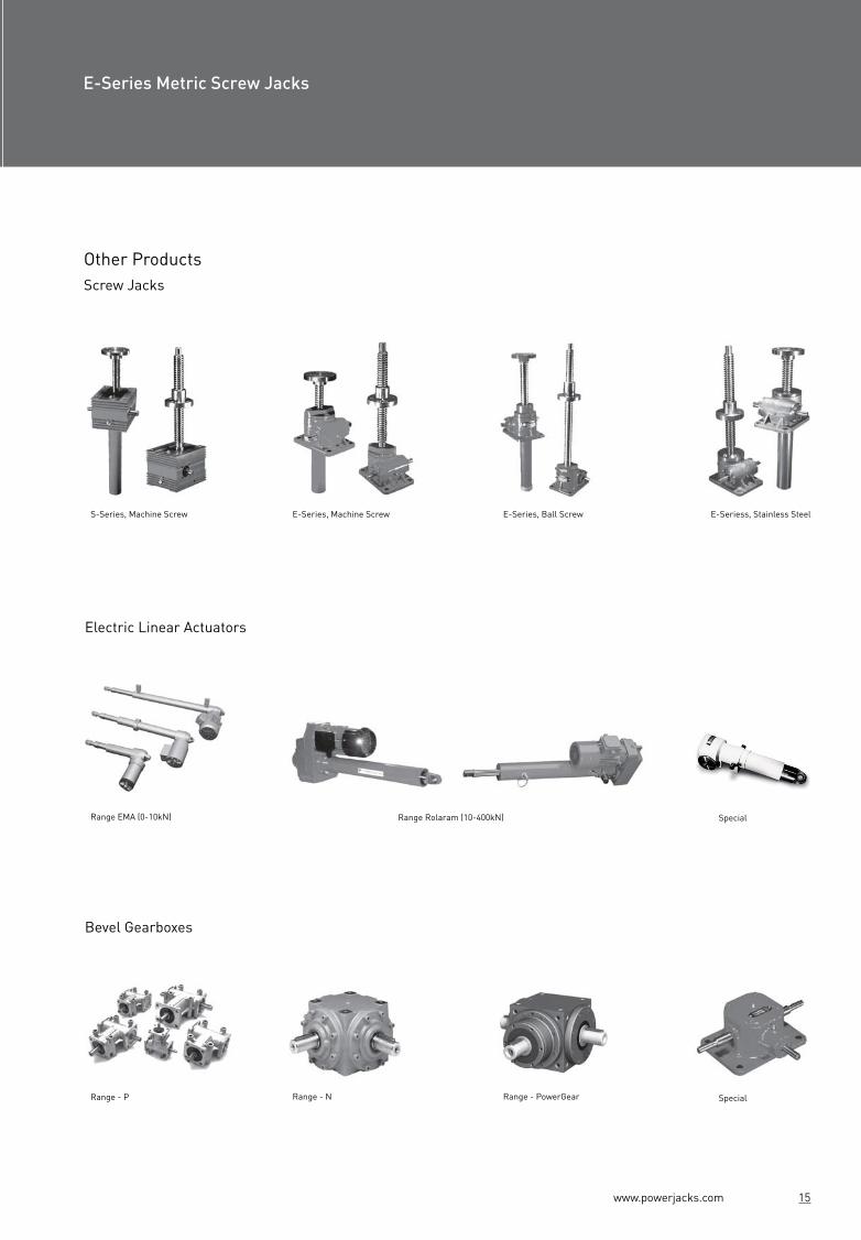
S-Series E-Series, Machine Screw E-Series, Ball Screw
Range - N Range - PowerGear
E-Seriess, Stainless Steel
Range EMA (0-10kN) Range Rolaram (10-400kN) Special
Range - P
Translating Screw (upright)
Rotating Screw (inverted)
Clevis
Rotating Screw (upright)
Translating Screw (inverted)
Threaded Special
Note:
Clockwise rotation of worm raises load on all models - counter clockwise available at extra charge.
Unless a translating lifting screw is keyed, the top should be bolted to the lifting member to prevent the screw from rotating.
Screw Jacks are equipped with “Alemite”grease fittings.
Recommended lubricants are listed in the installation andmaintenance instructions.
Screw Jacks supplied complete with drive shaft keys.
Bellows boots screw protection available on request.
Anti-backlash option for reduced axial screw backlash.
Secondary guide option for increased lateral rigidity.
Double clevis screw jack option.
Attachments
IEC and Nema motor flanges, motors, gearboxes, reducers and couplings available for single screw jacks or multiple jacking arrangements.
1. Metric Machine Screw JacksPrecise positioning repeatable, reliable performance, self-locking feature, over 5000 variants.
Other ProductsScrew Jacks
Electric Linear Actuators
Bevel Gearboxes

www.powerjacks.com www.powerjacks.com14 3
Stroke
3.3. Motor Adapters
Standard adapters for 25kN to 300kN Screw Jacks.
Standard is IEC motor frames.
NEMA frames available on request.
3.4. Bellows Boots
Bellows Boots Options
Protect the screw from dust and dirt.
Guards against moisture and corrosive contaminants.
Helps maintain the proper lubrication.
1.1. Standard Performance
Options:
* All metric machine screws have a trapezoidal thread form, single start as standard (diameter x pitch).† For loads of 25% to 100% of screw jack capacity, torque requirements are approximately proportional to the load.
3.5. Metric Double Clevis Screw Jacks 1.1.1. Screw Jack Efficiencies
Notes: Efficiency values for standard grease lubricated worm gear box and lifting screw.
Model E2625 E2501 E1802 E1805 E1810 E1820 E1830 E1850 E18100
Static efficiency
Dynamic efficiency
0.189
0.107
0.233
0.130
0.201
0.115
0.213
0.117
0.206
0.132
0.181
0.116
0.149
0.084
0.132
0.079
0.131
0.079
0.252
0.160
0.306
0.194
0.264
0.167
0.281
0.172
0.272
0.190
0.242
0.169
0.205
0.128
0.181
0.120
0.178
0.123
Screw jack model E2625 E2501 E1802 E1805 E1810 E1820 E1830 E1850 E18100
kN 5 10 25 50 100 200 300 500 1000Capacity
Lifting screw*
mm 16 x 3 20 x 5 30 x 6 40 x 9 55 x 12 65 x 12 95 x 16 120 x 16 160 x 20
Gear ratios
Turn of worm for travel of lifting screw
Max. input power (kW)
Start up torque at full load (Nm)†
Weight (kg) - stroke = 150mm
Weight (kg) - per extra 25mm
1.03
option 1
option 2
option 1
option 2
option 1
option 2
option 1
option 2
5:1
20:1
5:1
20:1
6:1
24:1
6:1
24:1
8:1
24:1
8:1
24:1
102/3 :1 102/3 :1
32:1 32:1
12:1
36:1
5 for 3mm 1 for 1mm 1 for 1mm 1 for 1.5mm 1 for 1.5mm1 for 1.5mm 1 for 1.5mm1 for 1.5mm 3 for 5mm
20 for 3mm 4 for 1mm 4 for 1mm 4 for 1.5mm 2 for 1mm 2 for 1mm 2 for 1mm 2 for 1mm 9 for 5mm
0.25
0.12
0.375
0.19
1.5
0.375
3
0.55
3.75
1.125
3.75
1.125
6
1.9
11.25
4.5
18.5
8.25
2.5
1.1
6.8
3.0
19.8
8.7
56.0
25.5
115.9
60.5
263.8
137
480
284
904
504
2025
1119
2.27 8.17 15.88 24.72 45 86 195 553
0.073 0.13 0.21 0.32 0.57 0.86 1.58 2.49 4.31
E-Series Metric Screw Jacks E-Series Metric Screw Jacks
option 2
option 1
option 2
option 1

www.powerjack.com www.powerjacks.com4 13
Upright Inverted
ModelsE18100
ModelsE1802 E1805 E1810 E1820 E1830 E1850
ModelsE2625 & E2501
LHS
RHS
LHS
RHSLHS
RHS
Top Plate Clevis End
25, 50 & 100 kN Models
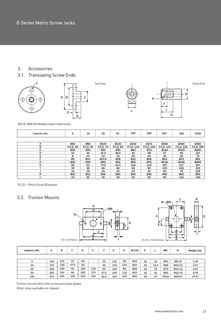
3. Accessories3.1. Translating Screw Ends
1.2. Dimensions1.2.1. Translating Screw Jacks
P.C.D. = Pitch Circle Diameter
Plan View
3.2. Trunion Mounts
Trunion mounts bolt onto screw jack base platesOther sizes available on request
500 & 1000 kN Models have 6 bolt holes
ABCDEFGHIJKL
Ø65P.C.D. 45
Ø25218
Ø9Ø25563015
Ø1015
5 kNCapacity 10 kN 25 kN 50 kN 100 kN 200 kN 300 kN 500 kN 1000 kN
Ø80P.C.D. 55
Ø302410
Ø11Ø30633618
Ø1220
Ø100P.C.D. 70
Ø4031.512
Ø13.5Ø4079.54623
Ø1630
Ø120P.C.D. 85
Ø5036.516
Ø18Ø5091.56030
Ø2035
Ø150P.C.D. 110
Ø654220
Ø22Ø651206633
Ø2240
Ø170P.C.D. 120
Ø755825
Ø26Ø751438040
Ø3050
Ø240P.C.D. 170
Ø1106730
Ø33Ø11016712060
Ø4580
Ø280P.C.D. 215
Ø1509235
Ø33Ø15021715075
Ø60110
Ø380P.C.D. 290
Ø20012775
Ø51Ø200297210105Ø90140
Capacity (kN)
5
10
25
50
100
A
114
175
160
200
270
B
114
135
120
160
200
C
57
67.5
60
80
100
D
60
80
165
205
225
E
-
-
135
170
180
F
30
40
50
57.5
52.5
G
110
130
110
150
190
H
85
100
80
115
145
ØJ (h6)
Ø15
Ø20
Ø25
Ø35
Ø45
K
20
25
30
40
50
L
10
12.5
15
20
25
ØM
Ø50
Ø58
Ø72
Ø95
Ø130
N
M8 (2)
M10 (2)
M12 (4)
M16 (4)
M20(4)
Weight (kg)(kg)
1.24
2.27
3.27
8.90
15.57
N
W M
H
DI
A
CAA
B
F
B
BB
C1
AE
G
S
U
TVN
OS
T
P R
WMN
X
Q O
VU U
K
J
P R
Q
WX
J
K
M
L
J
K
X
X
L
O
P R
Q
ØJE
F
NC
ØM
GBA
HL
K
D
LHS = Left Hand Side
RHS = Right Hand Side
E-Series Metric Screw Jacks E-Series Metric Screw Jacks
L
F
A B C
ED
LH
I
J
K
G
==
5 & 10 kN Models
HN
G
K
C
AB
L
FDØJ
ØM

www.powerjacks.com www.powerjacks.com12 5
Stroke
Pilot
Mounting Base
Bottom Pipe
Lifting Nut
Shell
1.2. DimensionsScrew Jack Models
2.3. Rotating Ball Screw Jacks 2.3.1. Upright Rotating Screw
2.3.2 Inverted Rotating Screw
Notes:
All dimensions in mm.
Closed height of threaded end and top plate units is the same for upright or inverted models.
Rotating screw jacks (refer 1.3) have the same dimensions for the shell as the translating screw type.
Dimensions are subject to change without notice.
A
B
C
C1D
E
F
G
H
I
J
K
L
M
N
O
P
Q
R
S
T
U
V
W
X
AA
BB
A + 9
95
40
Ø16
Ø26.7
26+0.13
10
M10 X 1.5
20
120
60
Ø10h8
3 X 3 X 18
Ø9
110
55
85
42.5
-
-
-
-
23.82
+ 0.076
- 0.000
27
64
64
E2625
E2624
5
Upright
Inverted
Capacity (kN)
E2501
E2500
10
E1802
E1801
25
E1805
E1804
50
E1810
E1809
100
E1820
E1819
200
E1830
E1829
300
E1850
E1849
500
E18100
E18099
1000
A + 10
125
45
Ø20
Ø33.4
40+0.13
10
M12 X 1.75
24
150
75
Ø14h8
5 X 5 X 25
Ø11
130
65
100
50
-
-
-
-
31.75
+ 0.076
- 0.000
35
90
78
A + 5
145
55
Ø30
Ø48.3
45+0.13
13
M20 X 2.5
30
180
90
Ø16h8
5 X 5 X 25
Ø13.5
110
55
80
40
165
65
135
50
43.26
+ 0.025
- 0.025
27.5
103.5
95.5
A - 5
185
65
Ø40
Ø60.3
60+0.13
14
M24 X 3
35
230
115
Ø19h8
6 X 6 X 32
Ø18
150
75
115
57.5
205
75
170
57.5
55.58
+ 0.050
- 0.000
35
138
122
A + 3
200
80
Ø55
Ø73
60+0.13
16
M36 X 4
40
280
140
Ø25h8
8 X 7 X 40
Ø22
190
95
145
72.5
225
75
180
52.5
66
+ 0.060
- 0.000
44
146.5
130.5
A - 1
265
95
Ø65
Ø89
85+0.13
20
M48 X 5
55
300
150
Ø28h8
8 X 7 X 40
Ø26
210
105
150
75
275
105
21575
66
+ 0.070
- 0.000
44
195
179
A + 15
325
115
Ø95
Ø115
105+0.13
30
M72 X 4
65
380
190
Ø35h8
10 X 8 X 50
Ø39
260
130
190
95
365
140
295
105
95.25
+ 0.130
- 0.000
56
235
235
A + 13
390
150
Ø120
Ø141
120+0.13
32
M100 X 4
90
460
230
Ø40h8
12 X 8 X 56
Ø51
300
150
200
100
535
225
435
175
135
+ 0.070
- 0.000
66
275
275
A + 3
560
260
Ø160
Ø194
150+0.13
40
M125 X 4
125
580
290
Ø45h8
14 X 9 X 70
Ø51
620
310
510
255
530
205
210
150
190.5
+ 0.076
- 0.000
88
405
405
Stroke as Required
UE3803
UE38031
UE3806
UE38061
UE3811
UE38111
UE3821
UE38211
UE3831
UE3861
Model (kN) A B C D ØE
ØK
F
25
50
100
200
300
500
25
30
50
65
85
103.5
138
146.5
195
235
0
0
28
24
40
Ø20
Ø25
Ø35
Ø45
Ø75
ØHG
15
20
25
35
48
Ø90
Ø120
Ø155
Ø185
Ø230
4 xØ13.5
4 xØ18
4 xØ22
4 xØ26
4 xØ26
AA + 85
AA + 110
AA + 110
AA + 160
AA + 135
AA + 160
AA + 176
AA + 190
AA + 240
I
65
96
90
136
108
132
150.5
160
200
UE28502 10 16 90 0 Ø12 12 Ø55
ØK (P.C.D.)
Ø45
Ø65
Ø90
Ø115
Ø135
Ø175
6 xØ7AA + 74 44
On Request
On Request
Ø40
Ø47
Ø60
Ø70
Ø75Ø85Ø95
Ø120
ØJ
Ø32
DE3803
DE38031
DE3806
DE38061
DE3811
DE38111
DE3821
DE38211
DE3831
DE3861
Model (kN) A B C D E ØF
25
50
100
200
300
500
25
30
50
65
95.5
122
130.5
179
13.5
18
26.5
25
95.5
122
130.5
203
ØIG
Ø20
Ø25
Ø35
Ø45
Ø90
Ø120
Ø155
Ø185
4 x Ø13.5
4 x Ø18
4 x Ø22
4 x Ø26
AA + 85
AA + 110
AA + 110
AA + 160
AA + 135
AA + 160
AA + 176
AA + 190
J ØK
65
96
90
136
108
132
150.5
160
DE28502 10 16 90 10 90 44
200
Ø55
H
15
20
25
35
85 235 25 275 Ø75 Ø230 4 x Ø2648
12
Ø65
Ø90
Ø115
Ø135
ØL (P.C.D.)
Ø175
Ø456 x Ø7AA+ 74
AA + 240
Ø12
Ø40
Ø47
Ø60
Ø70
Ø75Ø85Ø95
Ø120
Ø32
AAA C
F
DØH
I
ØJ ØE
B
G
Top Pipe
Mounting Base
Stroke
Pilot
Shell
Lifting Nut
E
C
D
A B AA
JG
H
ØF
ØKØL
ØI
E-Series Metric Screw Jacks E-Series Metric Screw Jacks
_ _ _ _ __ _ __
www.powerjacks.com www.powerjacks.com6 11
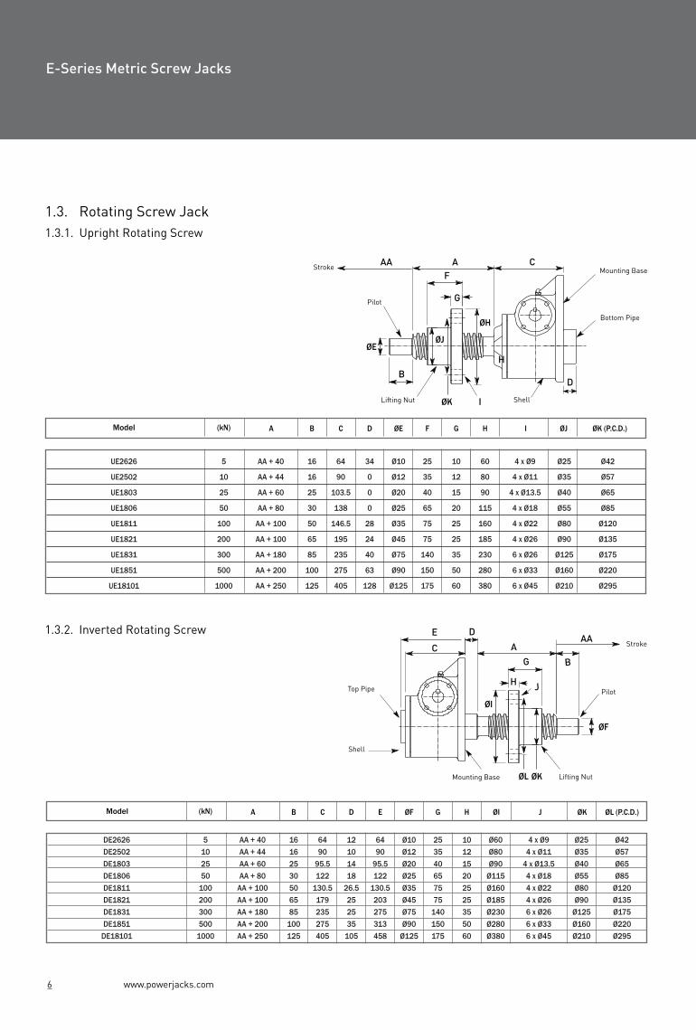
2.2.2. Screw Jack Model1.3. Rotating Screw Jack1.3.1. Upright Rotating Screw
1.3.2. Inverted Rotating Screw
Notes:
All dimensions in mm.
Closed height (C/C1) of threaded end and top plate units is the same for upright or inverted models.
Rotating screw jacks (refer 2.3) have the same dimensions for the shell as the translating screw type.
Dimensions are subject to change without notice.
Upright
Inverted
Capacity
UE2626
UE2502
UE1803
UE1806
UE1811
UE1821
UE1831
UE1851
UE18101
Model (kN) A B C D ØE F G H
5
10
25
50
100
200
300
500
1000
AA + 40
AA + 44
AA + 60
AA + 80
AA + 100
AA + 100
AA + 180
AA + 200
AA + 250
16
16
25
30
50
65
85
100
125
64
90
103.5
138
146.5
195
235
275
405
34
0
0
0
28
24
40
63
128
Ø10
Ø12
Ø20
Ø25
Ø35
Ø45
Ø75
Ø90
Ø125
25
35
40
65
75
75
140
150
175
10
12
15
20
25
25
35
50
60
60
80
90
115
160
185
230
280
380
ØK (P.C.D.)ØJ
Ø42
Ø57
Ø65
Ø85
Ø120
Ø135
Ø175
Ø220
Ø295
Ø25
Ø35
Ø40
Ø55
Ø80
Ø90
Ø125
Ø160
Ø210
I
4 x Ø9
4 x Ø11
4 x Ø13.5
4 x Ø18
4 x Ø22
4 x Ø26
6 x Ø26
6 x Ø33
6 x Ø45
DE2626
DE2502
DE1803
DE1806
DE1811
DE1821
DE1831
DE1851
DE18101
Model (kN) A B C D E ØF G H ØI
5
10
25
50
100
200
300
500
1000
AA + 40
AA + 44
AA + 60
AA + 80
AA + 100
AA + 100
AA + 180
AA + 200
AA + 250
16
16
25
30
50
65
85
100
125
64
90
95.5
122
130.5
179
235
275
405
12
10
14
18
26.5
25
25
35
105
64
90
95.5
122
130.5
203
275
313
458
Ø10
Ø12
Ø20
Ø25
Ø35
Ø45
Ø75
Ø90
Ø125
25
35
40
65
75
75
140
150
175
10
12
15
20
25
25
35
50
60
Ø60
Ø80
Ø90
Ø115
Ø160
Ø185
Ø230
Ø280
Ø380
J
4 x Ø9
4 x Ø11
4 x Ø13.5
4 x Ø18
4 x Ø22
4 x Ø26
6 x Ø26
6 x Ø33
6 x Ø45
ØL (P.C.D.)ØK
Ø42
Ø57
Ø65
Ø85
Ø120
Ø135
Ø175
Ø220
Ø295
Ø25
Ø35
Ø40
Ø55
Ø80
Ø90
Ø125
Ø160
Ø210
AB
B1C
C1DEFGHIJKLMNOPQRSTUV
W
XAABB
A + 10A + 25
55Ø25
Ø48.345 + 0.13
13M20 X 2.5
3018090
Ø16 h85 X 5 X 25
Ø13.5110558040
16565
13550
43.26+ 0.025- 0.025
27.5
A + 10A + 25
65Ø40
Ø60.360 + 0.13
14M24 X 3
35230115
Ø19 h86 X 6 X 32
Ø1815075
11557.520575
17057.5
55.58+ 0.050- 0.000
35
A + 15A + 25
80Ø50Ø73
60 + 0.1316
M36 X 440
280140
Ø25 h88 X 7 X 40
Ø2219095
14572.522575
18052.566
+ 0.060- 0.000
44
A + 10A + 25
95Ø63Ø89
85 + 0.1320
M48 X 555
300150
Ø28 h88 X 7 X 40
Ø2621010515075
2751052157566
+ 0.070- 0.000
44
E3802
E3801
E38021
E38011
E3805
E3804
E38051
E38041
E3810
E3809
E38101
E38091
E3820
E3819
200
E3830
E3829
300
Stroke as Required
25 50 100
E3860
E3859
500
175 202 218 269 252 275 338 386
134 161134
A + 35A + 35
15045
Ø20Ø42
40 + 0.139
M12 X 1.7524
15075
Ø14 h85 X 5 X 25
Ø1113065
10050----
31.75+ 0.076- 0.000
36
E28501
E28500
10
114114 161
172 223172 223
197 220197 220
268 316268 316
A + 30A + 25
115Ø80
Ø115105 + 0.13
30M72 X 4
65380190
Ø35 h810 X 8 X 50
Ø3926013019095
365140295105
95.25+ 0.130- 0.000
56
445
360360
On
Req
uest
E-Series Metric Screw Jacks E-Series Metric Screw Jacks
______
Top Pipe
Mounting Base
Stroke
Pilot
Shell
Lifting Nut
E D
C AAA
G B
JH
Stroke
Pilot
Mounting Base
Bottom Pipe
Lifting Nut Shell
ØH
ØK
ØJØE
B
CAAAF
D
H
I
G
ØF
ØKØL
ØI

www.powerjacks.com www.powerjacks.com10 7
Upright Inverted
ModelsE28501
ModelsE3802 E38021 E3805 E38051 E3810E38101 E3820 E38201 E3830 E3860
LHS
RHS
LHS
RHS
1.4. Keyed Metric Screw Jacks
Keyed translating screw jacks stop the screw from rotating withoutthe need for end pinning. However the keyway in the screw will causegreater than normal wear on the internal threads of the worm gear.
2.2. Ball Screw Jack Dimensions2.2.1. Translating Screw
**Consult Power Jacks
Plan View
1.5. Anti-Backlash
Anti-Backlash Option
Reduction in the axial backlash between the screw and the worm gearnut to a practical minimum. Acts as a safety device, providing a dualnut load carrying unit, when the worm gear becomes worn. Wearindicator for critical applications.
N
S
U
K
H
DI
A
C
B
AA
E
G
F
B
BB
C1
A
W
V
N
O
P R
Q
LM
J
X
K
X
J
M
W
T
V
L
O
PR
Q
LHS = Left Hand SideRHS = Right Hand Side
Model E2624 E2500 E1801 E1804 E1809 E1819 E1829 E1849 E1899
Inverted
A
B
C
79
AA + 9
Ø35
78
AA + 35
N/A
125.5
AA + 30
Ø60
79
AA + 20
Ø75
79
AA + 3
Ø90
210
AA + 1
Ø102
267
AA + 15
Ø141.5
**
**
**
**
**
**
B
C
A
AA
Upright(dimensions as standard versions)
Inverted
Stroke
E-Series Metric Screw Jacks E-Series Metric Screw Jacks

E-Series Metric Screw Jacks E-Series Metric Screw Jacks
www.powerjacks.com www.powerjacks.com8 9
Translating Screw (upright)
Clevis
Rotating Screw (upright)
Threaded
Note:
Integral safety device - All Power Jacks metric ball screw jacks except model E28501 have an integral safety device as standard. This provides two important safety roles:
(a) wear indicator and
(b) sustain the load in the unlikely event of catastrophic ball failure.
Bellows boots screw protection available on request.
Pre-loaded ball screw assembly for zero linear backlash option.
Secondary guide option for increased lateral rigidity.
Double clevis screw jack option.
Attachments
IEC and Nema motor flanges, motors, gearboxes, reducers and couplings available for single screw jacks or multiple jacking arrangements.
2. Metric Ball Screw JacksHigh efficiency. Precise and reliable positioning. Integral safety device.
2.1. Standard Performance
† For loads of 25% to 100% of screw jack capacity, torque requirements are approximately proportional to the load.
2.1.1. Ball Screw Jack Efficiencies
Notes: Efficiency values for standard grease lubricated worm gear box and lifting screw.
Screw Jack Model
Model
Model
Gear Ratio
Lifting Screw Pitch (mm)
Static Efficiency
Dynamic Efficiency
Gear Ratio
Lifting Screw Pitch (mm)
Static Efficiency
Dynamic Efficiency
E3802E28501 E3805 E3810 E3820 E3830 E3860
6:15:1
5
0.603
0.681
0.565 0.600
6:1
0.567 0.595
8:1
0.546 0.581
8:1
0.529 0.571
5 10 10 20 10 20 10 20
0.662 0.692 0.663 0.687 0.645 0.674 0.631 0.665
10 2/3 :1
0.492
20
0.595
0n Request
Capacity (kN)
Lifting Screw
Gear Ratios
Turn of worm for travel of lifting screw
DiameterPitch
E3802 E3805 E3810 E3820 E3830 E3860
Maximum input power (kW)
Start-up torque at full load (Nm) †
Weight (kg) - stroke = 150mm
Weight (kg) - per extra 25mm
25
25 mm
6:1
24:1
5 mm 10mm
12 for10 mm
48 for10 mm
6 for10 mm
24 for10 mm
1.5
0.375
8.17
0.21
5.9 11.1
2.6 4.9
E28501
10
20 mm
5:1
20:1
5 mm
10 for10 mm
40 for10 mm0.375
0.18
2.8
0.08
2.7
1.2
300
80 mm
10 2/3:1
20 mm
5.33 for10 mm
16 for10 mm
6
1.9
86
1.58
182
107.3
50
40 mm
6:1
24:1
10 mm 20mm
6 for10 mm
24 for10 mm
3 for10 mm
12 for10 mm
3
0.55
15.88
0.32
23.4 44.6
10.7 20.4
100
50 mm
8:1
24:1
10 mm 20mm
8 for10 mm
24 for10 mm
4 for10 mm
12 for10 mm
3.75
1.125
24.72
0.57
36.4 68.5
19.1 35.8
200
63 mm
8:1
24:1 32:1
10 mm 20mm
8 for10 mm
24 for10 mm
4 for10 mm
12 for10 mm
3.75
1.125
45
0.86
75.2 139.4
39.4 72.9
500
On
Req
uest
Gear Ratio = Option 1
Gear Ratio = Option 2
E3802E28501 E3805 E3810 E3820 E3830 E3860
24:120:1
5
0.341
0.429
0.320 0.340
24:1
0.310 0.325
24:1
0.348 0.370
24:1
0.337 0.364
5 10 10 20 10 20 10 20
0.419 0.438 0.407 0.422 0.450 0.470 0.440 0.465
32:1
0.278
20
0.371
On Request
option 1
option 1
option 1
option 1
option 2
option 2
option 2
option 2
Translating Screw (inverted) Rotating Screw (inverted)

E-Series Metric Screw Jacks E-Series Metric Screw Jacks
www.powerjacks.com www.powerjacks.com8 9
Translating Screw (upright)
Clevis
Rotating Screw (upright)
Threaded
Note:
Integral safety device - All Power Jacks metric ball screw jacks except model E28501 have an integral safety device as standard. This provides two important safety roles:
(a) wear indicator and
(b) sustain the load in the unlikely event of catastrophic ball failure.
Bellows boots screw protection available on request.
Pre-loaded ball screw assembly for zero linear backlash option.
Secondary guide option for increased lateral rigidity.
Double clevis screw jack option.
Attachments
IEC and Nema motor flanges, motors, gearboxes, reducers and couplings available for single screw jacks or multiple jacking arrangements.
2. Metric Ball Screw JacksHigh efficiency. Precise and reliable positioning. Integral safety device.
2.1. Standard Performance
† For loads of 25% to 100% of screw jack capacity, torque requirements are approximately proportional to the load.
2.1.1. Ball Screw Jack Efficiencies
Notes: Efficiency values for standard grease lubricated worm gear box and lifting screw.
Screw jack model
Model
Model
Gear ratio
Lifting screw pitch (mm)
Static efficiency
Dynamic efficiency
Gear ratio
Lifting screw pitch (mm)
Static efficiency
Dynamic efficiency
E3802E28501 E3805 E3810 E3820 E3830 E3860
6:15:1
5
0.603
0.681
0.565 0.600
6:1
0.567 0.595
8:1
0.546 0.581
8:1
0.529 0.571
5 10 10 20 10 20 10 20
0.662 0.692 0.663 0.687 0.645 0.674 0.631 0.665
10 2/3:1
0.492
20
0.595
0n Request
Capacity (kN)
Lifting screw
Gear ratios
Turn of worm for travel of lifting screw
Diameter
Pitch
E3802 E3805 E3810 E3820 E3830 E3860
Maximum input power (kW)
Start-up torque at full load (Nm) †
Weight (kg) - stroke = 150mm
Weight (kg) - per extra 25mm
25
25 mm
6:1
24:1
5 mm 10mm
12 for10 mm
48 for10 mm
6 for10 mm
24 for10 mm
1.5
0.375
8.17
0.21
5.9 11.1
2.6 4.9
E28501
10
20 mm
5:1
20:1
5 mm
10 for10 mm
40 for10 mm0.375
0.18
2.8
0.08
2.7
1.2
300
80 mm
10 2/3:1
20 mm
5.33 for10 mm
16 for10 mm
6
1.9
86
1.58
182
107.3
50
40 mm
6:1
24:1
10 mm 20mm
6 for10 mm
24 for10 mm
3 for10 mm
12 for10 mm
3
0.55
15.88
0.32
23.4 44.6
10.7 20.4
100
50 mm
8:1
24:1
10 mm 20mm
8 for10 mm
24 for10 mm
4 for10 mm
12 for10 mm
3.75
1.125
24.72
0.57
36.4 68.5
19.1 35.8
200
63 mm
8:1
24:1 32:1
10 mm 20mm
8 for10 mm
24 for10 mm
4 for10 mm
12 for10 mm
3.75
1.125
45
0.86
75.2 139.4
39.4 72.9
500
On
Req
uest
Gear Ratio = Option 1
Gear Ratio = Option 2
E3802E28501 E3805 E3810 E3820 E3830 E3860
24:120:1
5
0.341
0.429
0.320 0.340
24:1
0.310 0.325
24:1
0.348 0.370
24:1
0.337 0.364
5 10 10 20 10 20 10 20
0.419 0.438 0.407 0.422 0.450 0.470 0.440 0.465
32:1
0.278
20
0.371
On Request
option 1
option 1
option 1
option 1
option 2
option 2
option 2
option 2
Translating Screw (inverted) Rotating Screw (inverted)

www.powerjacks.com www.powerjacks.com10 7
Upright Inverted
ModelsE28501
ModelsE3802 E38021 E3805 E38051 E3810E38101 E3820 E38201 E3830 E3860
LHS
RHS
LHS
RHS
1.4. Keyed Metric Screw Jacks
Keyed translating screw jacks stop the screw from rotating withoutthe need for end pinning. However the keyway in the screw will causegreater than normal wear on the internal threads of the worm gear.
2.2. Ball Screw Jack Dimensions2.2.1. Translating Screw
**Consult Power Jacks
Plan View
1.5. Anti-Backlash
Anti-Backlash Option
Reduction in the axial backlash between the screw and the worm gearnut to a practical minimum. Acts as a safety device, providing a dualnut load carrying unit, when the worm gear becomes worn. Wearindicator for critical applications.
N
S
U
K
H
DI
A
C
B
AA
E
G
F
B
BB
C1
A
W
V
N
O
P R
Q
LM
J
X
K
X
J
M
W
T
V
L
O
PR
Q
LHS = Left Hand SideRHS = Right Hand Side
Model E2624 E2500 E1801 E1804 E1809 E1819 E1829 E1849 E1899
Inverted
A
B
C
79
AA + 9
Ø35
78
AA + 35
N/A
125.5
AA + 30
Ø60
79
AA + 20
Ø75
79
AA + 3
Ø90
210
AA + 1
Ø102
267
AA + 15
Ø141.5
**
**
**
**
**
**
B
C
A
AA
Upright(dimensions as standard versions)
Inverted
Stroke
E-Series Metric Screw Jacks E-Series Metric Screw Jacks

www.powerjacks.com www.powerjacks.com6 11
2.2.2. Screw Jack Model1.3. Rotating Screw Jack1.3.1. Upright Rotating Screw
1.3.2. Inverted Rotating Screw
Notes:
All dimensions in mm.
Closed height (C/C1) of threaded end and top plate units is the same for upright or inverted models.
Rotating screw jacks (refer 2.3) have the same dimensions for the shell as the translating screw type.
Dimensions are subject to change without notice.
Upright
Inverted
Capacity (kN)
UE2626
UE2502
UE1803
UE1806
UE1811
UE1821
UE1831
UE1851
UE18101
Model (kN) A B C D ØE F G H
5
10
25
50
100
200
300
500
1000
AA + 40
AA + 44
AA + 60
AA + 80
AA + 100
AA + 100
AA + 180
AA + 200
AA + 250
16
16
25
30
50
65
85
100
125
64
90
103.5
138
146.5
195
235
275
405
34
0
0
0
28
24
40
63
128
Ø10
Ø12
Ø20
Ø25
Ø35
Ø45
Ø75
Ø90
Ø125
25
35
40
65
75
75
140
150
175
10
12
15
20
25
25
35
50
60
60
80
90
115
160
185
230
280
380
ØK (P.C.D.)ØJ
Ø42
Ø57
Ø65
Ø85
Ø120
Ø135
Ø175
Ø220
Ø295
Ø25
Ø35
Ø40
Ø55
Ø80
Ø90
Ø125
Ø160
Ø210
I
4 x Ø9
4 x Ø11
4 x Ø13.5
4 x Ø18
4 x Ø22
4 x Ø26
6 x Ø26
6 x Ø33
6 x Ø45
DE2626
DE2502
DE1803
DE1806
DE1811
DE1821
DE1831
DE1851
DE18101
Model (kN) A B C D E ØF G H ØI
5
10
25
50
100
200
300
500
1000
AA + 40
AA + 44
AA + 60
AA + 80
AA + 100
AA + 100
AA + 180
AA + 200
AA + 250
16
16
25
30
50
65
85
100
125
64
90
95.5
122
130.5
179
235
275
405
12
10
14
18
26.5
25
25
35
105
64
90
95.5
122
130.5
203
275
313
458
Ø10
Ø12
Ø20
Ø25
Ø35
Ø45
Ø75
Ø90
Ø125
25
35
40
65
75
75
140
150
175
10
12
15
20
25
25
35
50
60
Ø60
Ø80
Ø90
Ø115
Ø160
Ø185
Ø230
Ø280
Ø380
J
4 x Ø9
4 x Ø11
4 x Ø13.5
4 x Ø18
4 x Ø22
4 x Ø26
6 x Ø26
6 x Ø33
6 x Ø45
ØL (P.C.D.)ØK
Ø42
Ø57
Ø65
Ø85
Ø120
Ø135
Ø175
Ø220
Ø295
Ø25
Ø35
Ø40
Ø55
Ø80
Ø90
Ø125
Ø160
Ø210
AB
B1C
C1DEFGHIJKLMNOPQRSTUV
W
XAABB
A + 10A + 25
55Ø25
Ø48.345 + 0.13
13M20 X 2.5
3018090
Ø16 h85 X 5 X 25
Ø13.5110558040
16565
13550
43.26+ 0.025- 0.025
27.5
A + 10A + 25
65Ø40
Ø60.360 + 0.13
14M24 X 3
35230115
Ø19 h86 X 6 X 32
Ø1815075
11557.520575
17057.5
55.58+ 0.050- 0.000
35
A + 15A + 25
80Ø50Ø73
60 + 0.1316
M36 X 440
280140
Ø25 h88 X 7 X 40
Ø2219095
14572.522575
18052.566
+ 0.060- 0.000
44
A + 10A + 25
95Ø63Ø89
85 + 0.1320
M48 X 555
300150
Ø28 h88 X 7 X 40
Ø2621010515075
2751052157566
+ 0.070- 0.000
44
E3802
E3801
E38021
E38011
E3805
E3804
E38051
E38041
E3810
E3809
E38101
E38091
E3820
E3819
200
E3830
E3829
300
Stroke as Required
25 50 100
E3860
E3859
500
175 202 218 269 252 275 338 386
134 161134
A + 35A + 35
15045
Ø20Ø42
40 + 0.139
M12 X 1.7524
15075
Ø14 h85 X 5 X 25
Ø1113065
10050----
31.75+ 0.076- 0.000
36
E28501
E28500
10
114114 161
172 223172 223
197 220197 220
268 316268 316
A + 30A + 25
115Ø80
Ø115105 + 0.13
30M72 X 4
65380190
Ø35 h810 X 8 X 50
Ø3926013019095
365140295105
95.25+ 0.130- 0.000
56
445
360360
On
Req
uest
E-Series Metric Screw Jacks E-Series Metric Screw Jacks
______
Top Pipe
Mounting Base
Stroke
Pilot
Shell
Lifting Nut
E D
C AAA
G B
JH
Stroke
Pilot
Mounting Base
Bottom Pipe
Lifting Nut Shell
ØH
ØK
ØJØE
B
CAAAF
D
H
I
G
ØF
ØKØL
ØI

www.powerjacks.com www.powerjacks.com12 5
Stroke
Pilot
Mounting Base
Bottom Pipe
Lifting Nut
Shell
1.2. DimensionsScrew Jack Models
2.3. Rotating Ball Screw Jacks 2.3.1. Upright Rotating Screw
2.3.2 Inverted Rotating Screw
Notes:
All dimensions in mm.
Closed height of threaded end and top plate units is the same for upright or inverted models.
Rotating screw jacks (refer 1.3) have the same dimensions for the shell as the translating screw type.
Dimensions are subject to change without notice.
A
B
C
C1D
E
F
G
H
I
J
K
L
M
N
O
P
Q
R
S
T
U
V
W
X
AA
BB
A + 9
95
40
Ø16
Ø26.7
26+0.13
10
M10 X 1.5
20
120
60
Ø10h8
3 X 3 X 18
Ø9
110
55
85
42.5
-
-
-
-
23.82
+ 0.076
- 0.000
27
64
64
E2625
E2624
5 kN
Upright
Inverted
Capacity
E2501
E2500
10 kN
E1802
E1801
25 kN
E1805
E1804
50 kN
E1810
E1809
100 kN
E1820
E1819
200 kN
E1830
E1829
300 kN
E1850
E1849
500 kN
E18100
E18099
1000 kN
A + 10
125
45
Ø20
Ø33.4
40+0.13
10
M12 X 1.75
24
150
75
Ø14h8
5 X 5 X 25
Ø11
130
65
100
50
-
-
-
-
31.75
+ 0.076
- 0.000
35
90
78
A + 5
145
55
Ø30
Ø48.3
45+0.13
13
M20 X 2.5
30
180
90
Ø16h8
5 X 5 X 25
Ø13.5
110
55
80
40
165
65
135
50
43.26
+ 0.025
- 0.025
27.5
103.5
95.5
A - 5
185
65
Ø40
Ø60.3
60+0.13
14
M24 X 3
35
230
115
Ø19h8
6 X 6 X 32
Ø18
150
75
115
57.5
205
75
170
57.5
55.58
+ 0.050
- 0.000
35
138
122
A + 3
200
80
Ø55
Ø73
60+0.13
16
M36 X 4
40
280
140
Ø25h8
8 X 7 X 40
Ø22
190
95
145
72.5
225
75
180
52.5
66
+ 0.060
- 0.000
44
146.5
130.5
A - 1
265
95
Ø65
Ø89
85+0.13
20
M48 X 5
55
300
150
Ø28h8
8 X 7 X 40
Ø26
210
105
150
75
275
105
21575
66
+ 0.070
- 0.000
44
195
179
A + 15
325
115
Ø95
Ø115
105+0.13
30
M72 X 4
65
380
190
Ø35h8
10 X 8 X 50
Ø39
260
130
190
95
365
140
295
105
95.25
+ 0.130
- 0.000
56
235
235
A + 13
390
150
Ø120
Ø141
120+0.13
32
M100 X 4
90
460
230
Ø40h8
12 X 8 X 56
Ø51
300
150
200
100
535
225
435
175
135
+ 0.070
- 0.000
66
275
275
A + 3
560
260
Ø160
Ø194
150+0.13
40
M125 X 4
125
580
290
Ø45h8
14 X 9 X 70
Ø51
620
310
510
255
530
205
210
150
190.5
+ 0.076
- 0.000
88
405
405
Stroke as Required
UE3803
UE38031
UE3806
UE38061
UE3811
UE38111
UE3821
UE38211
UE3831
UE3861
Model (kN) A B C D ØE
ØK
F
25
50
100
200
300
500
25
30
50
65
85
103.5
138
146.5
195
235
0
0
28
24
40
Ø20
Ø25
Ø35
Ø45
Ø75
ØHG
15
20
25
35
48
Ø90
Ø120
Ø155
Ø185
Ø230
4 xØ13.5
4 xØ18
4 xØ22
4 xØ26
4 xØ26
AA + 85
AA + 110
AA + 110
AA + 160
AA + 135
AA + 160
AA + 176
AA + 190
AA + 240
I
65
96
90
136
108
132
150.5
160
200
UE28502 10 16 90 0 Ø12 12 Ø55
ØK (P.C.D.)
Ø45
Ø65
Ø90
Ø115
Ø135
Ø175
6 xØ7AA + 74 44
On Request
On Request
Ø40
Ø47
Ø60
Ø70
Ø75Ø85Ø95
Ø120
ØJ
Ø32
DE3803
DE38031
DE3806
DE38061
DE3811
DE38111
DE3821
DE38211
DE3831
DE3861
Model (kN) A B C D E ØF
25
50
100
200
300
500
25
30
50
65
95.5
122
130.5
179
13.5
18
26.5
25
95.5
122
130.5
203
ØIG
Ø20
Ø25
Ø35
Ø45
Ø90
Ø120
Ø155
Ø185
4 x Ø13.5
4 x Ø18
4 x Ø22
4 x Ø26
AA + 85
AA + 110
AA + 110
AA + 160
AA + 135
AA + 160
AA + 176
AA + 190
J ØK
65
96
90
136
108
132
150.5
160
DE28502 10 16 90 10 90 44
200
Ø55
H
15
20
25
35
85 235 25 275 Ø75 Ø230 4 x Ø2648
12
Ø65
Ø90
Ø115
Ø135
ØL (P.C.D.)
Ø175
Ø456 x Ø7AA+ 74
AA + 240
Ø12
Ø40
Ø47
Ø60
Ø70
Ø75Ø85Ø95
Ø120
Ø32
AAA C
F
DØH
I
ØJ ØE
B
G
Top Pipe
Mounting Base
Stroke
Pilot
Shell
Lifting Nut
E
C
D
A B AA
JG
H
ØF
ØKØL
ØI
E-Series Metric Screw Jacks E-Series Metric Screw Jacks
_ _ _ _ __ _ __
www.powerjack.com www.powerjacks.com4 13
Upright Inverted
ModelsE18100
ModelsE1802 E1805 E1810 E1820 E1830 E1850
ModelsE2625 & E2501
LHS
RHS
LHS
RHSLHS
RHS
Top Plate Clevis End
25, 50 & 100 kN Models
3. Accessories3.1. Translating Screw Ends
1.2. Dimensions1.2.1. Translating Screw Jacks
P.C.D. = Pitch Circle Diameter
Plan View
3.2. Trunion Mounts
Trunion mounts bolt onto screw jack base platesOther sizes available on request
500 & 1000 kN Models have 6 bolt holes
ABCDEFGHIJKL
Ø65P.C.D. 45
Ø25218
Ø9Ø25563015
Ø1015
5Capacity (kN) 10 25 50 100 200 300 500 1000
Ø80P.C.D. 55
Ø302410
Ø11Ø30633618
Ø1220
Ø100P.C.D. 70
Ø4031.512
Ø13.5Ø4079.54623
Ø1630
Ø120P.C.D. 85
Ø5036.516
Ø18Ø5091.56030
Ø2035
Ø150P.C.D. 110
Ø654220
Ø22Ø651206633
Ø2240
Ø170P.C.D. 120
Ø755825
Ø26Ø751438040
Ø3050
Ø240P.C.D. 170
Ø1106730
Ø33Ø11016712060
Ø4580
Ø280P.C.D. 215
Ø1509235
Ø33Ø15021715075
Ø60110
Ø380P.C.D. 290
Ø20012775
Ø51Ø200297210105Ø90140
Capacity (kN)
5
10
25
50
100
A
114
175
160
200
270
B
114
135
120
160
200
C
57
67.5
60
80
100
D
60
80
165
205
225
E
-
-
135
170
180
F
30
40
50
57.5
52.5
G
110
130
110
150
190
H
85
100
80
115
145
ØJ (h6)
Ø15
Ø20
Ø25
Ø35
Ø45
K
20
25
30
40
50
L
10
12.5
15
20
25
ØM
Ø50
Ø58
Ø72
Ø95
Ø130
N
M8 (2)
M10 (2)
M12 (4)
M16 (4)
M20(4)
Weight (kg)
1.24
2.27
3.27
8.90
15.57
N
W M
H
DI
A
CAA
B
F
B
BB
C1
AE
G
S
U
TVN
OS
T
P R
WMN
X
Q O
VU U
K
J
P R
Q
WX
J
K
M
L
J
K
X
X
L
O
P R
Q
ØJE
F
NC
ØM
GBA
HL
K
D
LHS = Left Hand Side
RHS = Right Hand Side
E-Series Metric Screw Jacks E-Series Metric Screw Jacks
L
F
A B C
ED
LH
I
J
K
G
==
5 & 10 kN Models
HN
G
K
C
AB
L
FDØJ
ØM

www.powerjacks.com www.powerjacks.com14 3
Stroke
3.3. Motor Adapters
Standard adapters for 25kN to 300kN Screw Jacks.
Standard is IEC motor frames.
NEMA frames available on request.
3.4. Bellows Boots
Bellows Boots Options
Protect the screw from dust and dirt.
Guards against moisture and corrosive contaminants.
Helps maintain the proper lubrication.
1.1. Standard Performance
Options:
* All metric machine screws have a trapezoidal thread form, single start as standard (diameter x pitch).† For loads of 25% to 100% of screw jack capacity, torque requirements are approximately proportional to the load.
3.5. Metric Double Clevis Screw Jacks 1.1.1. Screw Jack Efficiencies
Notes: Efficiency values for standard grease lubricated worm gear box and lifting screw.
Model E2625 E2501 E1802 E1805 E1810 E1820 E1830 E1850 E18100
Static Efficiency
Dynamic Efficiency
0.189
0.107
0.233
0.130
0.201
0.115
0.213
0.117
0.206
0.132
0.181
0.116
0.149
0.084
0.132
0.079
0.131
0.079
0.252
0.160
0.306
0.194
0.264
0.167
0.281
0.172
0.272
0.190
0.242
0.169
0.205
0.128
0.181
0.120
0.178
0.123
Screw Jack Model E2625 E2501 E1802 E1805 E1810 E1820 E1830 E1850 E18100
kN 5 10 25 50 100 200 300 500 1000Capacity
Lifting screw*
mm 16 x 3 20 x 5 30 x 6 40 x 9 55 x 12 65 x 12 95 x 16 120 x 16 160 x 20
Gear ratios
Turn of worm for travel of lifting screw
Max. input power (kW)
Start up torque at full load (Nm)†
Weight (kg) - stroke = 150mm
Weight (kg) - per extra 25mm
1.03
option 1
option 2
option 1
option 2
option 1
option 2
option 1
option 2
5:1
20:1
5:1
20:1
6:1
24:1
6:1
24:1
8:1
24:1
8:1
24:1
102/3 :1 102/3 :1
32:1 32:1
12:1
36:1
5 for 3mm 1 for 1mm 1 for 1mm 1 for 1.5mm 1 for 1.5mm1 for 1.5mm 1 for 1.5mm1 for 1.5mm 3 for 5mm
20 for 3mm 4 for 1mm 4 for 1mm 4 for 1.5mm 2 for 1mm 2 for 1mm 2 for 1mm 2 for 1mm 9 for 5mm
0.25
0.12
0.375
0.19
1.5
0.375
3
0.55
3.75
1.125
3.75
1.125
6
1.9
11.25
4.5
18.5
8.25
2.5
1.1
6.8
3.0
19.8
8.7
56.0
25.5
115.9
60.5
263.8
137
480
284
904
504
2025
1119
2.27 8.17 15.88 24.72 45 86 195 553
0.073 0.13 0.21 0.32 0.57 0.86 1.58 2.49 4.31
E-Series Metric Screw Jacks E-Series Metric Screw Jacks
option 2
option 1
option 2
option 1
E-Series Metric Screw Jacks E-Series Metric Screw Jacks
www.powerjacks.com www.powerjacks.com2 15
S-Series, Machine Screw E-Series, Machine Screw E-Series, Ball Screw
Range - N Range - PowerGear
E-Seriess, Stainless Steel
Range EMA (0-10kN) Range Rolaram (10-400kN) Special
Range - P
Translating Screw (upright)
Rotating Screw (inverted)
Clevis
Rotating Screw (upright)
Translating Screw (inverted)
Threaded Special
Note:
Clockwise rotation of worm raises load on all models - counter clockwise available at extra charge.
Unless a translating lifting screw is keyed, the top should be bolted to the lifting member to prevent the screw from rotating.
Screw Jacks are equipped with “Alemite”grease fittings.
Recommended lubricants are listed in the installation andmaintenance instructions.
Screw Jacks supplied complete with drive shaft keys.
Bellows boots screw protection available on request.
Anti-backlash option for reduced axial screw backlash.
Secondary guide option for increased lateral rigidity.
Double clevis screw jack option.
Attachments
IEC and Nema motor flanges, motors, gearboxes, reducers and couplings available for single screw jacks or multiple jacking arrangements.
1. Metric Machine Screw JacksPrecise positioning repeatable, reliable performance, self-locking feature, over 5000 variants.
Other ProductsScrew Jacks
Electric Linear Actuators
Bevel Gearboxes

DESIGN WITH POWER
Head OfficeSouth Harbour RoadFraserburghAberdeenshireAB43 9BZScotland (UK)
FM 23810
2009 All rights reserved. PJSJB-E-EN-01
E-Series
Tel: +44 (0)1346 513131Fax: +44 (0) 1346 [email protected]
Designed and manufactured in Great Britain
Metric Machine Screw and Ball Screw Jacks
Power Jacks are an industry leader in the manufacture of qualityindustrial lifting, positioning,material handling and powertransmission equipment. The products are supplied globally tomost industry sectors including nuclear, water, oil & gas, chemical,defence, steel, aluminium, automotive, and others.
PRECISION SCREW JACKS . ELECTRIC LINEAR ACTUATORS .
PLANETARY ROLLER SCREWS . SPIRAL BEVEL GEARBOXES .

Voimansiirtokomponentit ja laitekokonaisuudet ovat meille tuttuja, sillä olemme yksi johtavista voimansiirtokomponenttien toimittajista Suomessa. Asiantuntijamme auttavat mielellään löytämään oikeat ratkaisut tarpeisiinne ja pystymme laajan tuotevalikoimamme ja kattavan varasto-ohjelman avulla nopeisiin toimituksiin.
Edustamme kansainvälisesti tunnettuja valmistajia ja tuotemerkkejä – tuotteiden ja toiminnan korkea laatu on yksi toimintamme kulmakivistä. Palvelemme teitä kaikissa voimansiirtoasioissanne yli neljänkymmenen vuoden kokemuksella.
Solutions for power transmission
www.konaflex.fi