Embed Size (px)
Citation preview
8102019 Power Handbook
httpslidepdfcomreaderfullpower-handbook 143
8102019 Power Handbook
httpslidepdfcomreaderfullpower-handbook 243
T H I R D E D I T I O N
The Electric Power Engineering Handbook
ELECTRIC POWERGENERATIONTRANSMISSION AND
DISTRIBUTION
8102019 Power Handbook
httpslidepdfcomreaderfullpower-handbook 343
CRC Press is an imprint of the
Taylor amp Francis Group an informa business
Boca Raton London New York
EDITED BY
LEONARD L GRIGSBY
T H I R D E D I T I O N
The Electric Power Engineering Handbook
ELECTRIC POWERGENERATIONTRANSMISSION AND
DISTRIBUTION
8102019 Power Handbook
httpslidepdfcomreaderfullpower-handbook 443
CRC Pressaylor amp Francis Group6000 Broken Sound Parkway NW Suite 300Boca Raton FL 33487-2742
copy 2012 by aylor amp Francis Group LLCCRC Press is an imprint of aylor amp Francis Group an Informa business
No claim to original US Government worksVersion Date 20111104
International Standard Book Number-13 978-1-4398-5637-6 (eBook - PDF)
his book contains information obtained from authentic and highly regarded sources Reasonable efforts have beenmade to publish reliable data and information but the author and publisher cannot assume responsibility for the valid-ity of all materials or the consequences of their use he authors and publishers have attempted to trace the copyrightholders of all material reproduced in this publication and apologize to copyright holders if permission to publish in thisform has not been obtained If any copyright material has not been acknowledged please write and let us know so we mayrectify in any future reprint
Except as permitted under US Copyright Law no part of this book may be reprinted reproduced transmitted or uti-lized in any form by any electronic mechanical or other means now known or hereafter invented including photocopy-ing microfilming and recording or in any information storage or retrieval system without written permission from thepublishers
For permission to photocopy or use material electronically from this work please access wwwcopyrightcom (httpwwwcopyrightcom) or contact the Copyright Clearance Center Inc (CCC) 222 Rosewood Drive Danvers MA 01923978-750-8400 CCC is a not-for-profit organization that provides licenses and registration for a variety of users Fororganizations that have been granted a photocopy license by the CCC a separate system of payment has been arranged
Trademark Notice Product or corporate names may be trademarks or registered trademarks and are used only foridentification and explanation without intent to infringe
Visit the Taylor amp Francis Web site at
httpwwwtaylorandfranciscom
and the CRC Press Web site at
httpwwwcrcpresscom
8102019 Power Handbook
httpslidepdfcomreaderfullpower-handbook 543
v
Contents
Preace ix
Editor x i
Contributors xiii
PART I Electric Power Generation Nonconventional Methods
Saiur Rahman -1
1 Wind Power -1Vaughn Nelson
2 Photovoltaic Fundamenta ls-1Roger A Messenger
3 Advanced Energy echnologies -1Saiur Rahman
4 Water -1Vaughn Nelson
PART II Electric Power Generation Conventional Methods
Rama Ramakumar -1
5 Hydroelectric Power Generation -1Steven R Brockschink James H Gurney and Douglas B Seely
6 Synchronous Machinery -1Paul I Nippes
7 hermal Generating Plants -1Kenneth H Sebra
8 Distributed Utilities -1 John R Kennedy and Rama Ramakumar
8102019 Power Handbook
httpslidepdfcomreaderfullpower-handbook 643
vi Contents
PART III Transmission System
George G Karady -1
9 Concept o Energy ransmission and Distribution -1
George G Karady 10 ransmission Line Structures -1
Joe C Pohlman
11 Insulators and Accessories -1George G Karady and Richard G Farmer
12 ransmission Line Construction and Maintenance-1 Jim Green Daryl Chipman and Yancy Gill
13 Insulated Power Cables Used in Underground Applications -1 Michael L Dyer
14 ransmission Line Parameters -1 Manuel Reta-Hernaacutendez
15 Sag and ension o Conductor -1Dale A Douglass and F Ridley Trash
16 Corona and Noise -1Giao N rinh
17 Geomagnetic Disturbances and Impacts upon Power System Operation -1 John G Kappenman
18 Lightning Protection -1William A Chisholm
19 Reactive Power Compensation -1Rao S Tallam and Geacuteza Jooacutes
20 Environmental Impact o ransmission Lines -1George G Karady
21 ransmission Line Reliability Methods -1Brian Keel Vishal C Patel and Hugh Stewart Nunn II
22 High-Voltage Direct Current ransmission System -1
George G Karady and Geacuteza Jooacutes 23 ransmission Line Structures -1
Robert E Nickerson Peter M Kandaris and Anthony M DiGioia Jr
24 Advanced echnology High-emperature Conductors -1 James R Hunt
8102019 Power Handbook
httpslidepdfcomreaderfullpower-handbook 743
viiContents
PART IV Distribution Systems
William H Kersting-1
25 Power System Loads -1
Raymond R Shoults and Larry D Swif 26 Distribution System Modeling and Analysis -1
William H Kersting
27 Power System Operation and Control -1George L Clark and Simon W Bowen
28 Hard to Find Inormation (on Distribution System Characteristicsand Protection) -1 Jim Burke
29 Real-ime Control o Distributed Generation -1
Murat Dilek and Robert P Broadwater
30 Distribution Short-Circuit Protection -1om A Short
PART V Electric Power Utilization
Andrew P Hanson -1
31 Metering o Electric Power and Energy -1 John V Grubbs
32 Basic Electric Power Utilization Loads Load Characterizationand Load Modeling -1 Andrew P Hanson
33 Electric Power Utilization Motors -1Charles A Gross
34 Linear Electric Motors -1 Jacek F Gieras
PART VI Power Quality
S Mark Halpin -1
35 Introduction -1S Mark Halpin
36 Wiring and Grounding or Power Quality -1Christopher J Melhorn
8102019 Power Handbook
httpslidepdfcomreaderfullpower-handbook 843
viii Contents
37 Harmonics in Power Systems -1S Mark Halpin
38 Voltage Sags -1 Math HJ Bollen
39 Voltage Fluctuations and Lamp Flicker in Power Systems -1S Mark Halpin
40 Power Quality Monitoring -1Patrick Coleman
8102019 Power Handbook
httpslidepdfcomreaderfullpower-handbook 943
ix
Preface
Te generation delivery and utilization o electric power and energy remain one o the most challeng-
ing and exciting 1047297elds o electrical engineering Te astounding technological developments o our age
are highly dependent upon a sae reliable and economic supply o electric power Te objective o the
Electric Power Engineering Handbook is to provide a contemporary overview o this ar-reaching 1047297eld
as well as a useul guide and educational resource or its study It is intended to de1047297ne electric powerengineering by bringing together the core o knowledge rom all o the many topics encompassed by
the 1047297eld Te chapters are written primarily or the electric power engineering proessional who seeks
actual inormation and secondarily or the proessional rom other engineering disciplines who wants
an overview o the entire 1047297eld or speci1047297c inormation on one aspect o it
Te 1047297rst and second editions o this handbook were well received by readers worldwide Based upon
this reception and the many recent advances in electric power engineering technology and applications
it was decided that the time was right to produce a third edition Because o the efforts o many indi-
viduals the result is a major revision Tere are completely new chapters covering such topics as FACS
smart grid energy harvesting distribution system protection electricity pricing linear machines In
addition the majority o the existing chapters have been revised and updated Many o these are major
revisionsTe handbook consists o a set o 1047297ve books Each is organized into topical parts and chapters in an
attempt to provide comprehensive coverage o the generation transormation transmission distribu-
tion and utilization o electric power and energy as well as the modeling analysis planning design
monitoring and control o electric power systems Te individual chapters are different rom most tech-
nical publications Tey are not journal-type articles nor are they textbooks in nature Tey are intended
to be tutorials or overviews providing ready access to needed inormation while at the same time pro-
viding sufficient reerences or more in-depth coverage o the topic
Tis book is devoted to the subjects o power system protection power system dynamics and stability
and power system operation and control I your particular topic o interest is not included in this list
please reer to the list o companion books reerred to at the beginning
In reading the individual chapters o this handbook I have been most avorably impressed by howwell the authors have accomplished the goals that were set Teir contributions are o course key to the
success o the book I grateully acknowledge their outstanding efforts Likewise the expertise and dedi-
cation o the editorial board and section editors have been critical in making this handbook possible o
all o them I express my proound thanks
Tey are as ollows
bull Nonconventional Power Generation Saiur Rahman
bull Conventional Power Generation Rama Ramakumar
bull ransmission Systems George G Karady
bull Distribution Systems William H Kersting
8102019 Power Handbook
httpslidepdfcomreaderfullpower-handbook 1043
x Preface
bull Electric Power Utilization Andrew P Hanson
bull Power Quality S Mark Halpin
bull ransormer Engineering (a complete book) James H Harlow
bull Substations Engineering (a complete book) John D McDonald
bull Power System Analysis and Simulation Andrew P Hanson
bull Power System ransients Pritindra Chowdhuribull Power System Planning (Reliability) Gerry Shebleacute
bull Power Electronics R Mark Nelms
bull Power System Protection Miroslav M Begovic
bull Power System Dynamics and Stability Prabha S Kundurdagger
bull Power System Operation and Control Bruce Wollenberg
I wish to say a special thank-you to Nora Konopka engineering publisher or CRC Pressaylor amp
Francis whose dedication and diligence literally gave this edition lie I also express my gratitude to the
other personnel at aylor amp Francis who have been involved in the production o this book with a spe-
cial word o thanks to Jessica Vakili Teir patience and perseverance have made this task most pleasant
Finally I thank my longtime riend and colleaguemdashMel Olken editor the Power and Energy
Magazinemdashor graciously providing the picture or the cover o this book
Arun Phadke or the 1047297rst and second editionsdagger Richard Farmer or the 1047297rst and second editions
8102019 Power Handbook
httpslidepdfcomreaderfullpower-handbook 1143
xi
Editor
received his BS and MS in electrical engi-
neering rom exas ech University Lubbock exas and his PhD rom
Oklahoma State University Stillwater Oklahoma He has taught electri-
cal engineering at exas ech University Oklahoma State University and
Virginia Polytechnic Institute and University He has been at AuburnUniversity since 1984 1047297rst as the Georgia power distinguished proessor
later as the Alabama power distinguished proessor and currently as pro-
essor emeritus o electrical engineering He also spent nine months dur-
ing 1990 at the University o okyo as the okyo Electric Power Company
endowed chair o electrical engineering His teaching interests are in net-
work analysis control systems and power engineering
During his teaching career Proessor Grigsby received 13 awards or teaching excellence Tese
include his selection or the university-wide William E Wine Award or eaching Excellence at Virginia
Polytechnic Institute and University in 1980 the ASEE Aamp Award or eaching Excellence in 1986
the 1988 Edison Electric Institute Power Engineering Educator Award the 1990ndash1991 Distinguished
Graduate Lectureship at Auburn University the 1995 IEEE Region 3 Joseph M Beidenbach OutstandingEngineering Educator Award the 1996 Birdsong Superior eaching Award at Auburn University and
the IEEE Power Engineering Society Outstanding Power Engineering Educator Award in 2003
Proessor Grigsby is a ellow o the Institute o Electrical and Electronics Engineers (IEEE) During
1998ndash1999 he was a member o the board o directors o IEEE as the director o Division VII or power
and energy He has served the institute in 30 different offices at the chapter section regional and inter-
national levels For this service he has received seven distinguished service awards such as the IEEE
Centennial Medal in 1984 the Power Engineering Society Meritorious Service Award in 1994 and the
IEEE Millennium Medal in 2000
During his academic career Proessor Grigsby has conducted research in a variety o projects related
to the application o network and control theory to modeling simulation optimization and control
o electric power systems He has been the major advisor or 35 MS and 21 PhD graduates With hisstudents and colleagues he has published over 120 technical papers and a textbook on introductory
network theory He is currently the series editor or the Electrical Engineering Handbook Series pub-
lished by CRC Press In 1993 he was inducted into the Electrical Engineering Academy at exas ech
University or distinguished contributions to electrical engineering
8102019 Power Handbook
httpslidepdfcomreaderfullpower-handbook 1243
8102019 Power Handbook
httpslidepdfcomreaderfullpower-handbook 1343
xiii
Contributors
Swedish ransmission Research Institute
Ludvika Sweden
Alabama Power Company
Birmingham Alabama
Department o Electrical Engineering
Virginia Polytechnic Institute and State
University
Blacksburg Virginia
Stantec Consulting
Portland Oregon
Quanta echnology
Raleigh North Carolina
Salt River Project
Phoenix Arizona
KinectricsUniversiteacute du Queacutebec agrave Chicoutimi
oronto Ontario Canada
Alabama Power Company
Birmingham Alabama
Alabama Power Company
Birmingham Alabama
DiGioia Gray and Associates LLC
Monroeville Pennsylvania
Electrical Distribution Design Inc
Blacksburg Virginia
Power Delivery Consultants Inc
Niskayuna New York
Salt River Project
Phoenix Arizona
School o Electrical Computer and Energy
Engineering
Arizona State University
empe Arizona
Department o Electrical Engineering
University o echnology and Lie Sciences
Bydgoszcz Poland
Salt River Project
Phoenix Arizona
8102019 Power Handbook
httpslidepdfcomreaderfullpower-handbook 1443
xiv Contributors
Salt River Project
Phoenix Arizona
Department o Electrical and ComputerEngineering
Auburn University
Auburn Alabama
Alabama Power Company
Birmingham Alabama
BC Hydro
Vancouver British Columbia Canada
Department o Electrical and Computer
Engineering
Auburn University
Auburn Alabama
Te Structure Group
Houston exas
Salt River Project
Phoenix Arizona
Department o Electrical and Computer
Engineering
McGill University
Montreal Quebec Canada
Salt River Project
Phoenix Arizona
Metatech Corporation
Duluth Minnesota
School o Electrical Computer and Energy
Engineering
Arizona State University
empe Arizona
Salt River Project
Phoenix Arizona
Georgia Power Company
Atlanta Georgia
Department o Electrical and ComputerEngineering
New Mexico State University
Las Cruces New Mexico
EPRI PEAC Corporation
Knoxville ennessee
Florida Atlantic University Boca Raton Florida
Alternative Energy Institute
West exas AampM University
Canyon exas
Consulting Engineer
Fort Worth exas
Magnetic Products and Services Inc
Holmdel New Jersey
Salt River Project
Phoenix Arizona
8102019 Power Handbook
httpslidepdfcomreaderfullpower-handbook 1543
xvContributors
Southern Caliornia Edison Company
Rosemead Caliornia
ConsultantPittsburgh Pennsylvania
Department o Electrical and Computer
Engineering
Virginia ech
Arlington Virginia
School o Electrical and Computer
EngineeringOklahoma State University
Stillwater Oklahoma
Electrical Engineering Academic Unit
Universidad Autoacutenoma de Zacatecas
Zacatecas Mexico
Baltimore Gas and Electric Company
Dameron Maryland
Stantec Consulting
Portland Oregon
Electric Power Research InstituteBurnt Hills New York
Department o Electrical Engineering
University o exas at Arlington
Arlington exas
f
Department o Electrical Engineering
University o exas at Arlington
Arlington exas
T
Salt River Project
Phoenix Arizona
y T
Southwire Company
Carrollton Georgia
Hydro-Queacutebec Institute o Research
Boucherville Quebec Canada
8102019 Power Handbook
httpslidepdfcomreaderfullpower-handbook 1643
34-1
Linear electric motors belong to the group o special electrical machines that convert electrical energy
directly into mechanical energy o translatory motion Linear electric motors can drive a linear-motion
load without intermediate gears screws or crank shafs Linear electric motors can be classi1047297ed as ollows
bull DC motorsbull Induction motors
bull Synchronous motors including reluctance and stepping motors
bull Oscil lating motors
bull Hybrid motors
Te application o DC linear motor is marginal Te most popular are permanent magnet (PM) linear
synchronous motors (LSMs) and linear induction motors (LIMs) which are manuactured commer-
cially in several countries and are 1047297nding many applications
A linear motor can be obtained by cutting a rotary motor along its radius rom the center axis o the
shaf to the external surace o the stator core and rolling it out 1047298at (Figure 341)
341 Linear Synchronous Motors3411 Basic Geometries and Constructions
An LSM is a linear motor in which the mechanical motion is in synchronism with the magnetic 1047297eld
ie the mechanical speed is the same as the speed o the traveling magnetic 1047297eld Te thrust (propulsion
orce) can be generated as an action o
bull raveling magnetic 1047297eld produced by a polyphase winding and an array o magnetic poles N
S hellip N S or a variable reluctance erromagnetic rail (LSMs with AC armature windings)
bull Magnetic 1047297eld produced by electronically switched DC windings and an array o magnetic poles N
S hellip N S or variable reluctance erromagnetic rail (linear stepping or switched reluctance motors)
34Linear Electric Motors
341 Linear Synchronous Motors -1Basic Geometries and Constructions bull Classi1047297cation bull Flux-
Switching PM Linear Motors bull Motors with Electromagnetic
Excitation bull Motors with Superconducting Excitation System
342 Linear Induction Motors -14
Basic Geometries and Constructions bullPropulsion o Wheel-on-Rail Vehicles
343 Variable Reluctance Motors -21344 Stepping Motors -22345 Switched Reluctance Motors -25346 Linear Positioning Stages -26Reerences -27
Jacek F GierasUniversity of Technology
and Life Sciences
8102019 Power Handbook
httpslidepdfcomreaderfullpower-handbook 1743
34-2 Electric Power Generation Transmission and Distribution
Te part producing the traveling magnetic 1047297eld is called the armature or orcer Te part that provides
the DC magnetic 1047298ux or variable reluctance is called the 1047297eld excitation system (i the excitation system
exists) or salient-pole rail reaction rail or variable reluctance platen Te terms primary and secondary
should rather be avoided as they are only justi1047297ed or LIMs [6] or transormers Te operation o an
LSM does not depend on which part is movable and which one is stationary
raditionally AC polyphase synchronous motors are motors with DC electromagnetic excitation the
propulsion orce o which has two components (1) due to the traveling magnetic 1047297eld and DC currentmagnetic 1047298ux (synchronous component) and (2) due to the traveling magnetic 1047297eld and variable reluc-
tance in d - and q-axes (reluctance component) Replacement o DC electromagnets with PMs is common
except or LSMs or magnetically levitated vehicles PM brushless LSMs can be divided into two groups
bull PM LSMs in which the input current waveorms are sinusoidal and produce a traveling magnetic
1047297eld
bull PM DC linear brushless motors (LBMs) with position eedback in which the input rectangular
or trapezoidal current waveorms are precisely synchronized with the speed and position o the
moving part
Construction o magnetic and electric circuits o LSMs belonging to both groups is the same LSMs can
be designed as 1047298at motors (Figure 342) or tubular motors (Figure 343) In DC brushless motors theinormation about the position o the moving part is usually provided by an absolute position sensor
Tis control scheme corresponds to an electronic commutation unctionally equivalent to the mechani-
cal commutation in DC commutator motors Tereore motors with square (trapezoidal) current wave-
orms are called DC brushless motors
Instead o DC or PM excitation the difference between the d - and q-axes reluctances and the traveling
magnetic 1047297eld can generate the reluctance component o the thrust Such a motor is called the AC vari-
able reluctance LSM Different reluctances in the d - and q-axes can be created by making salient erro-
magnetic poles using erromagnetic and nonerromagnetic materials or using anisotropic erromagnetic
materials Te operation o LBMs can be regarded as a special case o the operation o LSMs
1
1
2
2
x
x
v
v
z
z
y
(a)
(b)
y
0
0
1
1
2
2 x
xv
z z
v g
y y
0
0
1 2
21
y
v 0 x
z
d
g 1
g 2
x
z
y
v
0
Evolution o a rotary induction motor (a) solid-rotor induction motor into a 1047298at single-sided LIM
and (b) hollow-rotor induction motor into a 1047298at double-sided LIM 1 primary 2 secondary
8102019 Power Handbook
httpslidepdfcomreaderfullpower-handbook 1843
34-3Linear Electric Motors
In the case o LSMs operating on the principle o the traveling magnetic 1047297eld the speed v o the mov-
ing part is equal to synchronous speed v s ie
v v s= = =2 τ ω
πτ
(341)
Te synchronous speed v s o the traveling magnetic 1047297eld depends only on the input requency (angular
input requency ω = 2π ) and pole pitch τ It does not depend on the number o poles 2 p
As or any other linear-motion electrical machine the useul orce (thrust) F x is directly proportional
to the output power P out and inversely proportional to the speed v = v s ie
F
P
v x
out
s
=
(342)
Flat three-phase PM linear motors (Photo courtesy o Kollmorgen Radord VA)
ubular PM LSM Moving rod (reaction rail) contains circular PMs (Photo courtesy o Caliornia
Linear Drives Carlsbad CA)
8102019 Power Handbook
httpslidepdfcomreaderfullpower-handbook 1943
34-4 Electric Power Generation Transmission and Distribution
Direct electromechanical drives with LSMs or actory automation systems can achieve speeds exceeding
600 mmin = 36 kmh and acceleration o up to 360 ms2 [7] Te thrust density ie thrust per active sur-
ace 2 pτLi where Li is the effective width o the stack
F
p Lx
x
i
=2
(Nm2
τ)
(343)
o LSMs is higher than that o LIMs (Figure 344)
Te polyphase (usually three-phase) armature winding can be distributed in slots made in the orm
o concentrated-parameter coils or made as a coreless (air-cored) winding layer PMs are the most popu-
lar 1047297eld excitation systems or short traveling distances (less than 10 m) or example actory transporta-
tion or automation systems A long PM rail would be expensive Electromagnetic excitation is used in
high-speed passenger transportation systems operating on the principle o magnetic levitation (maglev)
Te German system ransrapid uses vehicle-mounted steel core excitation electromagnets and station-
ary slotted armatures Japanese MLX001 test train sets use onboard superconducting (SC) air-cored
electromagnets and a stationary three-phase air-cored armature winding distributed along the guide-
way (Yamanashi Maglev est Line)
3412 Classi1047297cation
LSMs can be classi1047297ed according to whether they are
bull Flat (planar) or tubular (cylindrical)
bull Single sided or double sided
bull Slotted or slotless
0
10000
20000
30000
40000
50000
60000
0 2000 4000 6000 8000 10000 12000 14000
Trust N
T h r u s t d e n s i t y N m 2
LSM OC
LSM WC
LSM AC
LSM NC
LIM NC
Comparison o thrust density or single-sided LIMs and LSMs AC air cooling NC natural cool-
ing OC oil cooling WC water cooling (From Gieras JF Status o linear motors in the United States International
Symposium on Linear Drives or Industry Applications (LDIArsquo03) Birmingham UK pp 169ndash176 2003)
8102019 Power Handbook
httpslidepdfcomreaderfullpower-handbook 2043
34-5Linear Electric Motors
bull Iron cored or air cored
bull ransverse 1047298ux or longitudinal 1047298ux
Te topologies mentioned earlier are possible or nearly all types o excitation systems LSMs operating
on the principle o the traveling magnetic 1047297eld can have the ollowing excitation systems
bull PMs in the reaction railbull PMs in the armature (passive reaction rail)
bull Electromagnetic excitation system (with winding)
bull SC excitation system
bull Passive reaction rail with saliency and neither PMs nor windings (variable reluctance motors)
LSMs with electronically switched DC armature windings are designed either as linear stepping motors
or linear switched reluctance motors
34121 PM Motors with Active Reaction Rail
Figure 345a shows a single-sided 1047298at LSM with the armature winding located in slots and surace PMs
Figure 345b shows a similar motor with buried-type PMs In surace arrangement o PMs the yoke(back iron) o the reaction rail is erromagnetic and PMs are magnetized in the normal direction (per-
pendicular to the active surace) Buried PMs are magnetized in the direction o the traveling magnetic
1047297eld and the yoke is nonerromagnetic or example made o aluminum (Al) Otherwise the bottom
leakage 1047298ux would be greater than the linkage 1047298ux as shown in Figure 346 Te same effect occurs in
buried-type PM rotors o rotary machines in which the shaf must also be nonerromagnetic [239]
Te so-called Halbach array o PMs also does not require any erromagnetic yoke and excites stronger
magnetic 1047298ux density and closer to the sinusoids than a conventional PM array Te key concept o the
Halbach array is that the magnetization vector should rotate as a unction o distance along the array
(Figure 347)
It is recommended that a PM LSM be urnished with a damper A rotary synchronous motor has a cage
damper winding embedded in pole shoe slots When the speed is different rom the synchronous speed
electric currents are induced in damper circuits Te action o the armature magnetic 1047297eld and damper
currents allows or asynchronous starting damps the oscillations and helps to return to synchronous
operation when the speed decreases or increases Also a damper circuit reduces the backward-traveling
magnetic 1047297eld It would be rather difficult to urnish PMs with a cage winding so that the damper o PM
LSMs has the orm o an Al cover (Figure 348a) or solid steel pole shoes (Figure 348b) In addition steel
pole shoes or Al cover (shield) can protect brittle PMs against mechanical damage
Te detent orce ie attractive orce between PMs and the armature erromagnetic teeth orce ripple
and some higher-space harmonics can be reduced with the aid o skewed assembly o PMs Skewed PMs
can be arranged in one row (Figure 349a) two rows (Figure 349b) or even more rows
1 3
(a) (b)
N
S
τ τ
S
N
1 2 3
N S
τ τ
S N
Single-sided 1047298at PM LSMs with slotted armature core and (a) surace PMs and (b) buried PMs
1 PM 2 mild steel pole 3 yoke
8102019 Power Handbook
httpslidepdfcomreaderfullpower-handbook 2143
34-6 Electric Power Generation Transmission and Distribution
(a)
(b)
Magnetic 1047298ux distribution in the longitudinal sections o buried-type PM LSMs (a) nonerromag-
netic yoke and (b) erromagnetic yoke (back iron)
1
2
Double-sided LSM with Halbach array o PMs 1 PMs 2 coreless armature winding
2
2
3(a)
(b)
3
1
1
Dampers o surace-type PM LSMs (a) Al cover (shield) and (b) solid steel pole shoes 1 PM
2 damper 3 yoke
8102019 Power Handbook
httpslidepdfcomreaderfullpower-handbook 2243
34-7Linear Electric Motors
Speci1047297cation data o 1047298at single-sided PM LBMs manuactured by Anorad are shown in able 341 [1]
and motors manuactured by Kollmorgen are shown in able 342 [11] Te temperature 25degC 125degC
or 130degC or the thrust current resistance and power loss is the temperature o the armature winding
Te electromotive orce (EMF) constant kE in ables 341 and 342 or sinusoidal operation is de1047297ned
according to the equation expressing the EMF (induced voltage) excited by PMs without the armature
reaction ie
E k v E s=
(344)
where v s is the synchronous speed according to Equation 341 Tus the armature constant kE multiplied
by the synchronous speed v s gives the EMF E
S SN N N N N N
N N N N N N
N N N N N N
S S S S
S S S S S S
S
(b)
(a)
S S S S S
Skewed PMs in 1047298at LSMs (a) one row and (b) two rows
Flat Tree-Phase Single-Sided PM LBMs with Natural Cooling Systems
Manuactured by Anorad Hauppauge NY
Parameter LCD--1 LCD--2-P LCD--3-P LCD--4-P
Continuous thrust at 25degC N 163 245 327 490
Continuous current at 25degC A 42 63 85 127
Continuous thrust at 125degC N 139 208 277 416
Continuous current at 125degC A 36 54 72 108
Peak thrust (025 s) N 303 455 606 909
Peak current (025 s) A 92 138 184 276
Peak orce (10 s) N 248 373 497 745
Peak current (10 s) A 73 110 147 220Continuous power losses at 125degC W 58 87 115 173
Armature constant kE Vsm 129
Trust constant (three phases) kF NA 386
Resistance per phase at 25degC Ω 32 22 16 11
Inductance mH 143 95 71 48
PM pole pitch mm 2345
Maximum winding temperature degC 125
Armature assembly mass kg 18 24 36 48
PM assembly mass kgm 64
Normal attractive orce N 1036 1555 2073 3109
8102019 Power Handbook
httpslidepdfcomreaderfullpower-handbook 2343
34-8 Electric Power Generation Transmission and Distribution
Te thrust constant kF in ables 341 and 342 is de1047297ned according to the simpli1047297ed equation or the
developed electromagnetic thrust ie
F k I dx F a= cos Ψ
(345)
or a sinusoidally excited LSM with equal reluctances in the d - and q-axes and or the angle between the
armature current I a and the q-axis Ψ = 0deg (cos Ψ = 1) Tus the thrust constant kF times the armature
current I a gives the electromagnetic thrust developed by the LSM
Double-sided 1047298at PM LSMs consist o two external armature systems and one internal excitation sys-
tem (Figure 3410a) or one internal armature system and two external excitation systems (Figure 3410b)
In the second case a linear Grammersquos armature winding can be used
In slotless motors the primary winding is uniormly distributed on a smooth armature core or does
not have any armature core Slotless PM LSMs are detent orcendashree motors provide lower torque ripple
and at high input requency can achieve higher efficiency than slotted LSMs On the other hand larger
nonerromagnetic air gap requires more PM material and the thrust density (thrust per mass or volume)
is lower than that o slotted motors (able 343) Te input current is higher as synchronous reactances
Flat Tree-Phase Single-Sided PM LBMs with Natural Cooling Systems
Manuactured by Kollmorgen Radord VA
Parameter IC11-030 IC11-050 IC11-100 IC11-200
Continuous thrust at 130degC N 150 275 600 1260
Continuous current at 130degC A 40 44 48 50
Peak thrust N 300 500 1000 2000
Peak current A 79 79 79 79
Continuous power losses at 130degC W 64 106 210 418
Armature constant at 25degC kE Vsm 309 514 1028 2057
Trust constant (three phases) at 25degC kF NA 378 629 1259 2519
Resistance line to line at 25degC Ω 19 26 44 80
Inductance line to line mH 173 278 541 1066
Electrical time constant ms 89 105 123 134
Termal resistance winding to external
structure degCW
164 099 050 025
Maximum winding temperature degC 130
Armature assembly mass kg 20 32 62 122PM assembly mass kgm 55 76 128 269
Normal attractive orce N 1440 2430 4900 9850
(a)
N S N SN S N S
N S N SN S N S
(b)
Double-sided 1047298at PM LSMs with (a) two external armature systems and (b) one internal armature
system
8102019 Power Handbook
httpslidepdfcomreaderfullpower-handbook 2443
34-9Linear Electric Motors
in the d - and q-axes can decrease to a low undesired value due to the absence o teeth Figure 3411a
shows a single-sided 1047298at slotless motor with armature core and Figure 3411b shows a double-sided slot-
less motor with inner air-cored armature winding (moving coil motor)
able 344 contains perormance speci1047297cations o double-sided PM LBMs with inner three-phase air-
cored armature winding manuactured by rilogy Systems Corporation Webster X (Figure 3412)
N
(a) (b)
S N S N S N S
S N NS
Flat slotless PM LSMs (a) single-sided with armature core and (b) double-sided with inner air-
cored armature winding
Slotted versus Slotless LSMs
Quantity Slotted LSM Slotless LSM
Higher thrust density X
Higher efficiency in the lower speed range X
Higher efficiency in the higher speed range x
Lower input current X
Less PM material X
Lower winding cost x
Lower thrust pulsations x
Lower acoustic noise x
Flat Double-Sided PM LBMs with Inner Tree-Phase Air-Cored Series-Coil
Armature Winding Manuactured by rilogy Systems Corporation Webster X
Parameter 310-2 310-4 310-6
Continuous thrust N 1112 2091 3149
Continuous power or sinusoidal operation W 87 152 230
Peak thrust N 356 712 1068
Peak power W 900 1800 2700
Peakcontinuous current A 10028 10026 10026
Trust constant kF or sinusoidal operation NA 400 800 1200
Trust constant kF or trapezoidal operation with Hallsensors NA
351 725 1095
Resistance per phase Ω 86 172 258
Inductance plusmn05 mH 60 120 180
Heat dissipation constant or natural cooling WdegC 110 201 301
Heat dissipation constant or orced air cooling WdegC 130 240 355
Heat dissipation constant or liquid cooling WdegC 154 285 421
Number o poles 2 4 6
Coil length mm 1422 2642 3861
Coil mass kg 055 103 153
Mass o PM excitation systems kgm 1267 or 838
8102019 Power Handbook
httpslidepdfcomreaderfullpower-handbook 2543
34-10 Electric Power Generation Transmission and Distribution
By rolling a lat LSM around the axis parallel to the direction o the traveling magnetic ield
ie parallel to the direction o thrust a tubular (cylindrical) LSM can be obtained (Figure 3413) A
tubular PM LSM can also be designed as a double-sided motor or slotless motor
ubular single-sided LSMs LinMoreg with movable internal PM excitation system (slider) and stationaryexternal armature are manuactured by Sulzer Electronics AG Zurich Switzerland (able 345) All active
motor parts bearings position sensors and electronics have been integrated into a rigid metal cylinder [14]
LinMotreg is a registered trademark o Sulzer Electronics AG Zuumlrich Switzerland
(b)(a)
N S N S N S
N S N S N S
N S N S
SNN S
Single-sided slotted tubular PM LSMs (a) with external armature system and (b) with external
excitation system
Data o ubular LSMs LinMotreg Manuactured by Sulzer Electronics AG Zuumlrich Switzerland
Parameter P01 23 times 80 P01 23 times 160 P01 37 times 120 P01 37 times 240
Number o phases 2
PMs NdFeB
Maximum stroke m 0210 0340 1400 1460Maximum orce N 33 60 122 204
Maximum acceleration ms2 280 350 247 268
Maximum speed ms 24 42 40 31
Stator (armature) length m 0177 0257 0227 0347
Stator outer diameter mm 23 23 37 37
Stator mass kg 0265 0450 0740 1385
Slider diameter mm 12 12 20 20
Maximum temperature o the armature winding degC 90
Flat double-sided PM LSM with inner moving coil (Photo courtesy o rilogy Systems Webster X)
8102019 Power Handbook
httpslidepdfcomreaderfullpower-handbook 2643
34-11Linear Electric Motors
All the aorementioned PM LSMs are motors with longitudinal magnetic 1047298ux the lines o which lie
in the plane parallel to the direction o the traveling magnetic 1047297eld LSMs can also be designed as trans-
verse magnetic 1047298ux motors in which the lines o magnetic 1047298ux are perpendicular to the direction o the
traveling 1047297eld Figure 3414a shows a single-sided transverse 1047298ux LSM in which PMs are arranged in two
rows A pair o parallel PMs creates a two pole 1047298ux excitation system A double-sided con1047297guration o
transverse 1047298ux motor is possible however it is complicated and expensive (Figure 3414b)
34122 PM Motors with Passive Reaction Rail
Te drawback o PM LSMs is the large amount o PM material that must be used to design the excitation
system Normally expensive rare-earth PMs are requested I a small PM LSM uses say 10 kg o NdFeB
per 1 m o the reaction rail and 1 kg o good-quality NdFeB costs US$ 130 the cost o the reaction rail
without assembly amounts to US$ 1300 per 1 m Tis price cannot be acceptable or example in pas-
senger transportation systems
A cheaper solution is to apply the PM excitation system to the short armature that magnetizes the
long reaction rail and creates magnetic poles in it Such a linear motor is called the homopolar LSM
Te homopolar LSM as described in [517] is a double-sided AC linear motor that consists o two
polyphase armature systems connected mechanically and magnetically by a erromagnetic U-type yoke
(Figure 3415) Each armature consists o a typical slotted linear motor stack with polyphase armature
winding and PMs located between the stack and U-type yoke Since the armature and excitation systems
are combined together the armature stack is oversized as compared with a conventional steel-cored LSM
Te PMs can also be replaced by electromagnets [1719] Te variable reluctance reaction rail is passive
Te saliency is created by using erromagnetic (solid or laminated) cubes separated by a nonerromag-netic material Te reaction rail poles are magnetized by the armature PMs through the air gap Te trav-
eling magnetic 1047297eld o the polyphase armature winding and salient poles o the reaction rail produce the
thrust Such a homopolar LSM has been proposed or the propulsion o maglev trains o Swissmetro [17]
Further simpli1047297cation o the double-sided con1047297guration can be made to obtain a single-sided PM
LSM shown in Figure 3416
3413 Flux-Switching PM Linear Motors
Large gantry systems and machining centers require powerul linear motors preerably with PM-ree
reaction rail Siemens 1FN6 PM LSMs with a magnet-ree reaction rail belong to the group o the so
5
(a) (b)
5
N S
N
N
3
4
4
3
2
6
1
3
6
1
6
1
i
S
2
2
N
N
SNN
S
ransverse 1047298ux PM LSM (a) single-sided and (b) double-sided 1 armature winding 2 armature
laminated core 3 PM 4 back erromagnetic core 5 magnetic 1047298ux 6 armature current
8102019 Power Handbook
httpslidepdfcomreaderfullpower-handbook 2743
34-12 Electric Power Generation Transmission and Distribution
called 1047298ux-switching PM machines [1016] Te armature system is air cooled degree o protection IP23
class o insulation F line voltage rom 400 to 480 V rated thrust rom 235 to 2110 N maximum veloc-
ity at rated thrust rom 170 to 540 mmin (able 346) overload capacity 38 o rated thrust modular
type construction [20] Tese LSMs operate with Siemens Sinamics or Simodrive solid-state converters
and external encoders According to Siemens [20] these new LSMs produce thrust orces and velocities
equivalent to competitive classical models or light-duty machine tool machine accessory and material
handling applications
2 3 244 1
N
S
S
N
N
S
S
N
5
Single-sided PM LSM with a passive reaction rail 1 PM 2 armature winding 3 armature stack
4 yoke 5 erromagnetic reaction rail
1
1
2 343
5
Fe Fe Fe Fe
Double-sided homopolar PM LSM with passive reaction rail 1 PM 2 armature winding
3 armature stack 4 yoke 5 reaction rail
Speci1047297cations o 1FN6 PM LSMs Manuactured by Siemens Erlangen Germany
Armature Unit Rated Trust N Max Trust N
Max Speed at
Rated Trust
mmin
Max Speed at
Max Trust
mmin
Rated
Current A Max Current A
1FN6008-1LC17 235ndash350 900 263 103 17ndash26 90
1FN6008-1LC37 235ndash350 900 541 224 35ndash53 180
1FN6016-1LC30 470ndash710 1800 419 176 54ndash80 280
1FN6016-1LC17 935ndash1400 3590 263 101 70ndash105 360
1FN6024-1LC12 705ndash1060 2690 176 69 35ndash53 180
1FN6024-1LC20 705ndash1060 2690 277 114 54ndash80 280
1FN6024-1LG10 2110ndash3170 8080 172 62 105ndash160 540
1FN6024-1LG17 2110ndash3170 8080 270 102 162ndash243 840
Source Synchronous Linear Motor 1FN6 Te Electrical Gear Rack Siemens AG Industry Sector Drive echnologies
Motion Control Erlangen Germany 2008
8102019 Power Handbook
httpslidepdfcomreaderfullpower-handbook 2843
34-13Linear Electric Motors
Te magnet-ree reaction rail is easy to install and does not require the saety considerations o stan-
dard PM reaction rails Without PMs there is no problem with errous chips and other debris beingattracted to these sections Maintenance becomes a simple matter o installing a wiper or brush on the
moving part o the slide
Te 1047298ux-switching LSM comprises an armature section that is equipped with coils and PMs as well
as a nonmagnetic toothed reaction rail section (Figure 3417) Te key design innovation is an LSM in
which PMs are integrated directly into the lamination o the armature core along with the individual
windings or each phase Both magnitudes and polarities o the linkage 1047298ux in the armature winding
vary periodically along with the reaction rail movement Te magnetic 1047298ux between the armature core
and steel reaction rail is controlled by switching the three-phase armature currents according to a desig-
nated algorithm Te passive reaction rail consists o milled steel with poles (teeth) and is much simpler
to manuacture
3414 Motors with Electromagnetic Excitation
Te electromagnetic excitation system o an LSM is similar to the salient-pole rotor o a rotary
synchronous motor Figure 3418 shows a 1047298at single-sided LSM with salient erromagnetic poles and
DC 1047297eld excitation winding Te poles and pole shoes can be made o solid steel laminated steel or sin-
tered powder I the electromagnetic excitation system is integrated with the moving part the DC cur-
rent can be delivered with the aid o brushes and contact bars inductive power transer (IP) systems
linear transormers or linear brushless exciters
A AB BC C
1
2
3
4
5
v
τ2
τ1
Construction o 1047298ux-switching LSM with PM-ree reaction rail 1 laminated armature core
2 PM 3 armature coil (phase C) 4 toothed passive steel reaction rail 5 linkage magnetic 1047298ux (phase A is on)
1
3
τ τ
2
S
d d q q q
4
N
Electromagnetic excitation system o a 1047298at single-sided iron-cored LSM 1 salient pole 2 DC
excitation winding 3 erromagnetic rail (yoke) 4 armature system
8102019 Power Handbook
httpslidepdfcomreaderfullpower-handbook 2943
34-14 Electric Power Generation Transmission and Distribution
LSMs with electromagnetic excitation (wound-1047297eld reaction rail) are used in German ransrapid
maglev train (Figure 3419)
3415 Motors with Superconducting Excitation System
In large-power LSMs the electromagnets with erromagnetic core that produce the excitation 1047298ux can
be replaced by coreless SC electromagnets Since the magnetic 1047298ux density produced by the SC electro-
magnet is greater than the saturation magnetic 1047298ux density o the best laminated alloys ( Bsat asymp 24 or
cobalt alloy) there is no need to use the armature erromagnetic core An LSM with SC 1047297eld excitation
system is a totally air-cored machine (Figure 3420)
Experimental maglev trains on the Yamanashi Maglev est Line (YML) in Yamanashi Preecture(west rom okyo) Japan are driven by air-cored LSMs with SC excitation systems ( Figure 3421)
342 Linear Induction Motors
LIMs have ound the widest prospects or applications in transportation systems beginning with electri-
cal traction on small passenger or material supply cars (used at airports exhibitions electrohighways
elevators) and ending with pallet transportation waer transportation belt conveyors transportation
systems o bulk materials etc Te second important place or LIM applications is in industry ie man-
uacturing processes (machine tools hammers presses mills separators automated manuacturing systems
strip tensioners textile shuttles index tables turntables disk saws or wood sliding doors robots etc)
ransrapid 09 maglev train driven by LSMs with electromagnetic excitation (Photo courtesy oTyssen ransrapid System GmbH Munich Germany)
1
2A
B
C B
A
A
C
S SN
τ τ τ τ τ
N N
CBA
Tree-phase air-cored LSM with SC excitation system 1 armature coils 2 SC excitation coils
8102019 Power Handbook
httpslidepdfcomreaderfullpower-handbook 3043
34-15Linear Electric Motors
LIMs can also play an important part in industrial investigations and tests or example high acceleration
o model aircraf in aerodynamic tunnels high acceleration o vessels in laboratory pools propulsion o
mixers shakers and vibrators and adjusting xndashy tables and instruments Tere is also a possibility o
using LIMs in consumer electronics (sound and vision equipment knitting machines curtains) and in
offices (transportation o documents letters and cash) Te Handbook o Linear Motor Applications [21]
printed in Japan in 1986 contains about 50 examples o applications o LIMs in operation or in the pro-
cess o implementation
3421 Basic Geometries and Constructions
A LIM can be obtained by cutting in the same way either a cage rotor induction motor or a wound rotor
induction motor Te stator becomes the primary and the rotor becomes the secondary [12] Te secondary
o a LIM can be simpli1047297ed by using a solid steel core and replacing the cage (ladder) or slip-ring winding with
a high-conductivity nonerromagnetic plate (Al or Cu) Te nonerromagnetic plate is a secondary electric
circuit with distributed parameters and the erromagnetic core is a conductor both or the magnetic 1047298ux
and the electric current It does not matter rom the principle o operation point o view which part (primary
or secondary) is in motion Tus the 1047298at single-sided LIM can be obtained rom a solid rotor induction
motor (Figure 341a) and the 1047298at double-sided LIM can be obtained rom a hollow-rotor induction motor
with wound external and internal stator (Figure 341b) In a double-sided LIM the secondary erromagneticcore is not necessary since the magnetic 1047298ux excited by one o the primary windings afer passing through
the air gaps and nonerromagnetic secondary is then closed up by the core o the second primary unit
Teoretically a double-sided LIM with primary windings located on two cores in comparison with a
single-sided LIM exciting the same MMF has twice the air gap magnetic 1047298ux density Tereore the thrust
o such a motor is our times greater assuming the same dimensions I only one primary core is wound
the output parameters o a double-sided LIM are the same as those or a single-sided LIM with laminated
secondary back iron Te undamental advantage o double-sided LIMs is the elimination o the normal
attractive orce between the primary and the secondary because the secondary is usually nonerromagnetic
Flat LIMs can have primary cores consisting o an array o cores arranged in parallel at appropri-
ate distances and connected magnetically by additional yokes perpendicular to the direction o the
YML in Yamanashi Preecture (near okyo) Japan YML maglev trains use air-cored LSMs
with SC excitation system (Photo courtesy o Central Japan Railway Company and Railway echnical Research
Institute okyo Japan)
8102019 Power Handbook
httpslidepdfcomreaderfullpower-handbook 3143
34-16 Electric Power Generation Transmission and Distribution
traveling 1047297eld A magnetic circuit designed in such a way makes it possible to apply two windings in
general multiphase windings with perpendicular conductors as shown in Figure 3422 Adjusting the
current in each winding the secondary can be moved in two perpendicular directions and can be posi-
tioned at any point o the xndashy plane A 1047298at LIM with two degrees o reedom (DOFs) can be designed both
as single-sided and double-sided machines
By rolling a 1047298at single-sided or double-sided LIM around the axis parallel to the direction o the travel-
ing magnetic 1047297eld ie parallel to the direction o the thrust a tubular motor can be obtained (Figure 3423)
A tubular (cylindrical) LIM similar to a 1047298at LIM can be designed both as single-sided and double-
sided machines and can have a square or rectangular cross section as in Figure 3424 Tere are possible
Te primary o a 1047298at LIM with two DOFs
g
g
g 1
g 2
(c)
(b)
(a)
d
v
v
v
1
1
1 1
1
1
2
2
2
2
2
2
ubular LIMs (a) single-sided with an external short primary (b) single-sided with an external
short secondary and (c) double-sided with short primary 1 primary 2 secondary
8102019 Power Handbook
httpslidepdfcomreaderfullpower-handbook 3243
34-17Linear Electric Motors
con1047297gurations other than that in Figure 3423 regarding the length o the secondary with respect to thelength o the primary
All the aorementioned LIMs are motors with longitudinal magnetic 1047298ux ie the lines o magnetic
1047298ux lie in the plane parallel to the direction o the traveling magnetic 1047297eld A LIM can also be designed
in such a way as to obtain magnetic 1047298ux lines perpendicular to the direction o the traveling 1047297eld Such
motors are said to have transverse magnetic 1047298ux (Figure 3425)
Te undamental advantage o a LIM with transverse magnetic 1047298ux in comparison with a LIM with
longitudinal magnetic 1047298ux is the lower magnetizing current necessary due to the shorter magnetic 1047298ux
paths Te signi1047297cant disadvantage is lower thrust A 1047298at LIM with transverse magnetic 1047298ux usually has
a primary winding o concentrated coils located on salient poles
A 1047298at single-sided LIM with transverse 1047298ux can produce not only thrust but also electrodynamic
suspension In the design shown in Figure 3426 the secondary is suspended electrodynamically andpropelled and stabilized laterally by the primary magnetic 1047297eld [8] Te primary magnetic circuit con-
sists o E-shaped laminations assembled in two rows Te short secondary is made o light Al alloy in the
orm o a boat Te lateral sides o the boat are inclined by 60deg with respect to the active surace Such a
shape provides maximum normal repulsive orce and maximum lateral stabilization
According to their geometry the LIMs can be divided into the ollowing groups
bull With movable primary or movable secondary
bull Single sided and double sided
bull Flat and tubular
bull With short primary and short secondary
bull With longitudinal and transverse magnetic 1047298ux
1 2 3 4 1 2 3 4
ubular double-sided LIM with a square cross section 1 primary 2 secondary 3 primary coil
4 internal core
v
v
1 1
1
1
(a)
(b)
22
22
Flat LIM with transverse magnetic 1047298ux and salient poles (a) single-sided and (b) double-sided
1 primary 2 secondary
8102019 Power Handbook
httpslidepdfcomreaderfullpower-handbook 3343
34-18 Electric Power Generation Transmission and Distribution
Te linear speed o a LIM is
v s v s= minus( )1 (346)
where
s is the slip
v s is the synchronous speed according to Equation 341
Neglecting the longitudinal end effect [6] the electromagnetic thrust developed by a LIM can be
expressed in a similar way as or a rotary induction motor ie
F
m
v I
R
sdx
s
= prime( ) prime1
2
2 2
(347)
where
m1 is the number o phases o the primary winding
v s is the synchronous speed according to Equation 341
primeI 2 is the secondary current reerred to the primary system
primeR2 is the secondary resistance reerred to the primary system
s is the slip
Te secondary resistance primeR2 must include the so-called edge effect [6]
3422 Propulsion of Wheel-on-Rail Vehicles
Modern railway systems and electrical traction should meet the ollowing requirements
bull High level o automatization and computerization
bull Propulsion and braking independent o adhesion which in turn is affected 1047297rst o all by climate
and weather
bull Low level o noise sometimes below 70 dB (A)
Flat LIM with transverse magnetic 1047298ux salient poles and nonerromagnetic secondary pro-
pelled suspended and stabilized electrodynamically (From Gieras JF et al Analytical calculation o electro-
dynamic levitation orces in a special-purpose linear induction motor International Electric Machines and Drives
Conerence (IEMDCrsquo11) Niagara Falls Ontario Canada 2011 [on CD-ROM])
8102019 Power Handbook
httpslidepdfcomreaderfullpower-handbook 3443
34-19Linear Electric Motors
bull Ability to cope with high slopes at least 6 and sharp bends with radius o curvature less than 20 m
bull No pollution to natural environment and landscape
bull High reliability
Te congestion problems o big cities should be solved by creating collective transport orms that can be
implemented without affecting a highly populated city For example there are many cities in Italy where
the historical center has remained the same since the Renaissance A heavy railway might be a com-
pletely wrong solution and have a notable impact on the city planning An adequate solution might be
a light railway a people mover with transport capacity o 10000ndash20000 passengers per hour to replace
the traditional transport nets and to integrate the existing railway nets
All the requirements mentioned earlier can be met by using LIMs as propulsion machines Replacing
electrical rotary motors with linear motors in traction drives (electrical locomotives) generally does
not require new tracks but only their adjustment to linear drives Single-sided LIMs (Figure 3427a and b)
are best since the normal attractive orce o these can strengthen the adhesion o wheels and rails
Te air gap is rom 10 to 15 mm Most requently the motor car has two LIMs with short primaries
(Figure 3427a) assembled in series Te double-layer secondary consists o a solid back iron and an Al
cap and is located between the rails Cables or computer communication with the vehicle and quite
ofen collectors or electrical energy delivery to the vehicle are located along the track Tree-phaseLIMs are ed rom variable-voltage variable-requency (VVVF) voltage-source inverters A linear pro-
pulsion system o wheel-on-rail vehicles allows more 1047298exibility (Figure 3428) reducing noise on bends
and wear o the wheels and rails
Double-sided LIMs (Figure 3427c and d) have ound very limited application due to the technical
difficulty o eliminating aults caused by bends in the secondary with primary cores on either side It is
more difficult to keep a small and uniorm air gap in double-sided LIMs than that in single-sided LIMs
Te LIM-driven wheel-on-rail vehicles are built or low velocities ie less than 100 kmh and or
short routes ie less than 50 km (urban transit systems and short-distance trains) At present LIM-
driven trains operate in oronto and Vancouver BC Canada in Detroit MI (Figure 3429) okyo
(Figure 3430) and Osaka Japan and Kuala Lumpur Malaysia
(a) (b)
(c) (d)
LIM-driven wheel-on-rail cars (a) single-sided LIM with short primary mounted on the undercar-
riage (b) single-sided LIM with short secondary mounted on the undercarriage (c) double-sided LIM with short pri-
mary mounted on the undercarriage and (d) double-sided LIM with short secondary mounted on the undercarriage
8102019 Power Handbook
httpslidepdfcomreaderfullpower-handbook 3543
34-20 Electric Power Generation Transmission and Distribution
(a) (b)
Te undercarriage o a wheel-on-rail vehicle (a) rotary motor propulsion and (b) LIM propulsion
Detroit people mover driven by single-sided LIMs
oei Oedo subway line in okyo driven by single-sided LIMs
8102019 Power Handbook
httpslidepdfcomreaderfullpower-handbook 3643
34-21Linear Electric Motors
Te design data o some single-sided traction LIMs are presented in able 347 and double-sided trac-
tion LIMs in able 348
343 Variable Reluctance Motors
Te simplest construction o a variable reluctance LSM or linear reluctance motor (LRM) is that shown
in Figure 3418 with DC excitation winding being removed However the thrust o such a motor wouldbe low as the ratio o d -axis permeance to q-axis permeance is low Better perormance can be obtained
when using 1047298ux barriers [18] or steel laminations [15] o make 1047298ux barriers any nonerromagnetic
materials can be used o obtain high permeance (low reluctance) in the d -axis and low permeance in
the q-axis steel laminations should be oriented in such a way as to create high permeance or the d -axis
magnetic 1047298ux
Figure 3431a shows a variable reluctance platen with 1047298ux barriers and Figure 3431b shows how to
arrange steel laminations to obtain different reluctances in the d - and q-axes Te platen can be com-
posed o segments the length o which is equal to the pole pitchτ Each segment consists o semicircular
lamellas cut out rom electrotechnical sheet A 1047297lling or example epoxy resin is used to make the seg-
ment rigid and robust By putting the segments together a platen o any desired length can be obtained
Design Data o Single-Sided Tree-Phase LIMs or Propulsion o Vehicles
Quantity
LIM
UnitJLMDR ICS KU CIGG GEC
Pullout thrust at requency given
in the ollowing F x
125 90 35 17 07 kN
Input requency 200 400 250 400 600 Hz
Rated phase current V 1 2750 4650 1300 2000 2000 A
Number o poles 2 p 8 6 4 6 4 mdash
Number o turns per phase N 1 128 96 128 108 48 mdash
Equivalent diameter o conductor d 1 mdash 893 528 1115 81 mm
Number o parallel conductors mdash 1 mdash 19 1 mdash
Effective width o primary core Li 023 0216 029 0101 01715 m
Pole pitch τ 027 02868 030 025 020 m
Length o single end connection l e mdash 03483 mdash 02955 03685 m
Coil pitch wc 0225 01673 025 01944 01555 m
Air gap g 150 126 120 150 182 mm
Number o slots z 1( primez 1) 96(106) 72(79) 48(58) 54(61) 36(43) mdash
Width o slot b11 mdash 156 170 150 1308 mm
Width o slot opening b14 mdash 156 mdash 1044 1308 mm
Depth o slot h11 mdash 530 380 3421 6147 mm
Height o yoke h1 y mdash 436 393 7163 500 mm
Conductivity o back iron at 20degC σFe mdash 446 952 446 512 times106 Sm
Conductivity o Al cap at 20degC σ Al mdash 300 303 323 215 times106 Sm
Width o back iron w 03 024 03 0111 01715 m
Tickness o back iron hsec 190 125 250 254 474 mm
Tickness o Al cap d 50 45 50 45(25) 32 mm
Tickness o Al cap behind Fe core t ov 50 170 50 127 32 mm
Width o Al cap 030 032 040 0201 02985 m
JLMDR Japanese Linear Motor Driven Railcar Japan ICS Intermediate Capacity ransit System Canada KU
Kyushu University LIM Japan CIGG Canadian Inst o Guided Ground ransport Canada GEC General
Electric Company United States (z 1 ) is the number o hal 1047297lled slots
8102019 Power Handbook
httpslidepdfcomreaderfullpower-handbook 3743
34-22 Electric Power Generation Transmission and Distribution
344 Stepping Motors
A linear stepping motor has a concentrated armature winding wound on salient poles and PM excitation
rail or variable reluctance platen Te thrust is generated as an action o the armature magnetic 1047298ux and
PM 1047298ux (active platen) or the armature magnetic 1047298ux and salient erromagnetic poles (variable reluc-
tance platen) Stepping motors have no position eedback
Design Data o Double-Sided Tree-Phase LIMs or Propulsion
o Vehicles
Quantity
LIM
UnitGEC LIMVR
Maximum thrust at input requency F x given in the ollowing 085 1668 kN
Input requency 600 1730 Hz
Input phase current I 1 2000 20000 A
Number o poles 2 p 4 10 mdash
Number o turns per phase N 1 144 100 mdash
Diameter o conductor d 1 075 110 mm
Effective width o primary core Li 00869 0254 m
Pole pitch τ 01795 03556 m
Coil pitch wc 005 005 m
Number o slots z 1( primez 1) 36(45) 150(160) mdash
Width o slot b11 137 160 mm
Width o slot opening b14 137 mdash mm
Depth o slot h1 630 mdash mm
Height o yoke h1 y 239 mdash mm
Width o tooth c1 200 77 mm
Resultant air gap 2 g + d 381 38075 mm
Air gap g 2 times 127 2 times 111 mm
Tickness o secondary d 127 15875(hollow) mm
Effective thickness o Al secondary 127 72 mm
Width o secondary w ge03046 mdash m
Conductivity o Al cap at 20degC σ Al asymp2434 asymp240 times106 Sm
GEC General Electric Company United States LIMVR LIM Research Vehicle
Pueblo CO United States (z 1 ) is the number o hal 1047297lled slots
(a) (b)
q q d d d q d q d d
Laminations
τ τ τ τ
Epoxy resin
Variable reluctance LSMs with (a) 1047298ux barriers and (b) steel laminations
8102019 Power Handbook
httpslidepdfcomreaderfullpower-handbook 3843
8102019 Power Handbook
httpslidepdfcomreaderfullpower-handbook 3943
34-24 Electric Power Generation Transmission and Distribution
Tis value is different or ull-step and microstepping drives Te maximum startndashstop speed is the
maximum speed that can be used when starting or stopping the motor without ramping that does not
cause the motor to all out o synchronism or lose steps Te maximum speed is the maximum linear
speed that can be achieved without the motor stalling or alling out o synchronism Te maximum
load mass is the maximum allowable mass applied to the orcer against the scale that does not result in
mechanical damage Te ull-step resolution is the position increment obtained when the currents are
switched rom one winding to the next winding Tis is the typical resolution obtained with ul l-step
drives and it is strictly a unction o the motor construction Te microstepping resolution is the position
increment obtained when the ull-step resolution is divided electronically by proportioning the currents
in the two windings Tis resolution is typically 10ndash250 times smaller than the ull-step resolution [13]
HLSMs are regarded as an excellent solution to positioning systems that require a high accuracy
and rapid acceleration With a microprocessor controlled microstepping mode a smooth operation with
standard resolution o a ew hundred stepsmm can be obtained Te advantages such as high efficiencyhigh throughput mechanical simplicity high reliability precise open-loop operation and low inertia
o the system have made these kind o motors more and more attractive in such applications as actory
automation high speed positioning computer peripherals acsimile machines numerically controlled
machine tools automated medical equipment automated laboratory equipment and welding robots
Tis motor is especially suitable or machine tools printers plotters and computer-controlled material
handling in which a high positioning accuracy and repeatability are the key problems
When two or our orcers mounted at 90deg and a special grooved platen (ldquowaffle platerdquo) are used the
xndashy motion (two DOFs) in a single plane is obtained (Figure 3434)
Speci1047297cation data o the xndashy HLSMs manuactured by Normag Northern Magnetics Inc Santa
Clarita CA are given in able 3410
PM linear stepping motors (Photo courtesy o okyo Aircraf Instrument Co Ltd okyo Japan)
8102019 Power Handbook
httpslidepdfcomreaderfullpower-handbook 4043
34-25Linear Electric Motors
345 Switched Reluctance Motors
Te topology o a linear switched reluctance motor is similar to that o a stepping motor with variable
reluctance platen In addition it is equipped with position sensors Te turn-on and turn-off instant o
the input current is synchronized with the position o the moving part Te thrust is very sensitive to
the turn-on and turn-off instant
In the case o a linear stepping or linear switched reluctance motor the speed v o the moving part is
v v s sw= = τ
(348)
where
sw is the undamental switching requency in one armature phase winding
τ is the pole pitch o the reaction rail
For a rotary stepping or switched reluctance motor sw = 2 pr n where 2 pr is the number o rotor poles and
n is rotational speed in revs
A linear switched reluctance motor has a doubly salient magnetic circuit with a polyphase winding
on the armature Longitudinal and transverse 1047298ux designs are shown in Figure 3435 A linear switched
reluctance motor allows precise speed and position-controlled linear motion at low speeds and is not sub-
ject to design constraints (minimum speed limited by minimum easible pole pitch) o linear AC motors
x
y
12
3
4
1
1
2
2
HLSM with a our-unit orcer to obtain the xndashy motion 1 orcers or the x -direction 2 orcers
or the y -direction 3 platen 4 air pressure
Data o xndashy HLSMs Manuactured by Normag Northern Magnetics Inc
Santa Clarita CA
Parameter 4XY0602-2-0 4XY2002-2-0 4XY2004-2-0 4XY2504-2-0
Number o orcer units per axis 1 1 2 2
Number o phases 2 2 2(4) 2(4)Static thrust N 133 400 980 1330
Trust at 1 ms N 111 311 712 980
Normal attractive orce N 1600 4000 14400 18000
Resistance per phase Ω 29 33 16 19
Inductance per phase mH 15 40 20 23
Input phase current A 20 20 40 40
Air gap mm 002
Maximum temperature degC 110
Mass kg 32 072 20 15
Repeatability mm 000254
Resolution mm 000254
Bearing type Air
8102019 Power Handbook
httpslidepdfcomreaderfullpower-handbook 4143
34-26 Electric Power Generation Transmission and Distribution
346 Linear Positioning Stages
Linear motors are now playing a key role in advanced precision linear positioning Linear precision posi-
tioning systems can be classi1047297ed into open-loop systems with HLSMs and closed-loop servo systems
with LSMs LBMs or LIMs
A PM LSMndashdriven positioning stage is shown in Figure 3436 A stationary base is made o Al steel
ceramic or granite plate It provides a stable precise and 1047298at platorm to which all stationary position-
ing components are attached Te base o the stage is attached to the host system with the aid o mount-
ing screws
Te moving table accommodates all moving positioning components o achieve maximum accelera-
tion the mass o the moving table should be as small as possible and usually Al is used as a lightweight
material A number o mounting holes on the moving table is necessary to 1047297x the payload to the mount-
ing table
Linear bearing rails provide a precise guidance to the moving table A minimum o one bearing rail
is required Linear ball bearing or air bearings are attached to each rail
Te armature o a linear motor is astened to the moving table and reaction rail (PM excitation sys-tem) is built in the base between the rails (Figure 3436)
A linear encoder is needed to obtain precise control o position o the table velocity and acceleration
Te read head o the encoder is attached to the moving table
(a) (b)
3
3
221
1
Linear switched reluctance motor con1047297gurations (a) longitudinal 1047298ux design and (b) transverse
1047298ux design 1 armature winding 2 armature stack 3 platen
12
3
5
4
7
6
8
Linear positioning stage driven by PM LBM 1 base 2 moving table 3 armature o LBM 4 PMs
5 linear bearing 6 encoder 7 cable carrier 8 limit switch (Courtesy o Normag Santa Clarita CA)
8102019 Power Handbook
httpslidepdfcomreaderfullpower-handbook 4243
34-27Linear Electric Motors
Noncontact limit switches ixed to the base provide an overtravel protection and init ial homing
A cable carrier accommodates and routes electrical cables between the moving table and stationary
connector box 1047297xed to the base
An HLSM-driven linear precision stage is o similar construction Instead o PMs between bearing
rails it has a variable reluctance platen HLSMs usually need air bearings and in addition to the electri-
cal cables an air hose between air bearings and the compressor is requiredLinear positioning stages are used in semiconductor technology electronic assembly quality assur-
ance laser cutting optical scanning water jet cutting gantry systems (x y z stages) color printers
plotters and Cartesian coordinate robotics
References
1 Anorad Linear Motors Inormation Brochure Anorad Hauppauge New York 2007 wwwanoradcom
2 Boldea I and Nasar SA Linear Motion Electromagnetic Systems John Wiley amp Sons New York 1985
3 Boldea I and Nasar SA Linear Electric Actuators and Generators Cambridge University Press
New York 2005
4 Compumotor Digiplan Positioning Control Systems and Drives Parker Hanni1047297n CorporationRohnert Park CA 2011
5 Everes W Henneberger G Wunderlich H and Selig A A linear homopolar motor or a trans-
portation system 2nd International Symposium on Linear Drives or Industry Applications (LDIArsquo98)
okyo Japan 1998 pp 46ndash49
6 Gieras JF Linear Induction Drives Clarendon Press Oxord UK 1994
7 Gieras JF Status o linear motors in the United States International Symposium on Linear Drives
or Industry Applications (LDIArsquo03) Birmingham UK 2003 pp 169ndash176
8 Gieras JF Gientkowski Z Mews J and Splawski P Analytical calculation o electrodynamic
levitation orces in a special-purpose linear induction motor International Electric Machines and
Drives Conerence (IEMDCrsquo11) Niagara Falls Ontario Canada 2011 [on CD-ROM]
9 Gieras JF Piech ZJ and omczuk BZ Linear Synchronous Motors ransportation and Automation Systems aylor amp Francis (CRC Press) Boca Raton FL 2011
10 Hoang E Ahmed AHB and Lucidarme J Switching 1047298ux permanent magnet polyphase syn-
chronous machines 7th European Conerence on Power Electronics and Applications (EPErsquo97)
Vol 3 rondheim Norway 1977 pp 903ndash908
11 Kollmorgen Linear Motors Aim to Cut Cost o Semiconductors and Electronics Manuacture
Kollmorgen Radord VA 1997
12 Laithwaite ER A History o Linear Electric Motors Macmillan London UK 1987
13 Linear Step Motor Inormation Brochure okyo Aircraf Instrument Co Ltd okyo Japan
1998
14 LinMot Design Manual Sulzer Electronics Ltd Zuumlrich Switzerland 1999
15 Locci N and Marongiu I Modelling and testing a new linear reluctance motor InternationalConerence on Electrical Machines (ICEMrsquo92) Vol 2 Manchester UK 1992 pp 706ndash710
16 Rauch SE and Johnson LJ Design principles o 1047298ux-switch alternators AIEE rans Part III
74(12) 1261ndash1269 1955
17 Rosenmayr M Casat Glavitsch A and Stemmler H SwissmetromdashPower supply or a high-
power-propulsion system with short stator linear motors 15th International Conerence on
Magnetically Levitated Systems and Linear Drives Maglevrsquo98 Mount Fuji Yamanashi Japan 1998
pp 280ndash286
18 Sanada M Morimoto S and akeda Y Reluctance equalization design o multi 1047298ux barrier con-
struction or linear synchronous reluctance motors 2nd International Symposium on Linear Drives
or Industrial Applications (LDIArsquo98) okyo Japan 1998 pp 259ndash262
8102019 Power Handbook
httpslidepdfcomreaderfullpower-handbook 4343
34-28 Electric Power Generation Transmission and Distribution
19 Seok-Myeong J and Sang-Sub J Design and analysis o the linear homopolar synchronous motor
or integrated magnetic propulsion and suspension 2nd International Symposium on Linear Drives
or Industrial Applications (LDIArsquo98) okyo Japan 1998 pp 74ndash77
20 Synchronous Linear Motor 1FN6 Te Electrical Gear Rack Siemens AG Industry Sector Drive
echnologies Motion Control Erlangen Germany 2008
21 Yamada H Handbook o Linear Motor Applications (in Japanese) Kogyo Chosaki Publishing Cookyo Japan 1986
8102019 Power Handbook
httpslidepdfcomreaderfullpower-handbook 343
CRC Press is an imprint of the
Taylor amp Francis Group an informa business
Boca Raton London New York
EDITED BY
LEONARD L GRIGSBY
T H I R D E D I T I O N
The Electric Power Engineering Handbook
ELECTRIC POWERGENERATIONTRANSMISSION AND
DISTRIBUTION
8102019 Power Handbook
httpslidepdfcomreaderfullpower-handbook 443
CRC Pressaylor amp Francis Group6000 Broken Sound Parkway NW Suite 300Boca Raton FL 33487-2742
copy 2012 by aylor amp Francis Group LLCCRC Press is an imprint of aylor amp Francis Group an Informa business
No claim to original US Government worksVersion Date 20111104
International Standard Book Number-13 978-1-4398-5637-6 (eBook - PDF)
his book contains information obtained from authentic and highly regarded sources Reasonable efforts have beenmade to publish reliable data and information but the author and publisher cannot assume responsibility for the valid-ity of all materials or the consequences of their use he authors and publishers have attempted to trace the copyrightholders of all material reproduced in this publication and apologize to copyright holders if permission to publish in thisform has not been obtained If any copyright material has not been acknowledged please write and let us know so we mayrectify in any future reprint
Except as permitted under US Copyright Law no part of this book may be reprinted reproduced transmitted or uti-lized in any form by any electronic mechanical or other means now known or hereafter invented including photocopy-ing microfilming and recording or in any information storage or retrieval system without written permission from thepublishers
For permission to photocopy or use material electronically from this work please access wwwcopyrightcom (httpwwwcopyrightcom) or contact the Copyright Clearance Center Inc (CCC) 222 Rosewood Drive Danvers MA 01923978-750-8400 CCC is a not-for-profit organization that provides licenses and registration for a variety of users Fororganizations that have been granted a photocopy license by the CCC a separate system of payment has been arranged
Trademark Notice Product or corporate names may be trademarks or registered trademarks and are used only foridentification and explanation without intent to infringe
Visit the Taylor amp Francis Web site at
httpwwwtaylorandfranciscom
and the CRC Press Web site at
httpwwwcrcpresscom
8102019 Power Handbook
httpslidepdfcomreaderfullpower-handbook 543
v
Contents
Preace ix
Editor x i
Contributors xiii
PART I Electric Power Generation Nonconventional Methods
Saiur Rahman -1
1 Wind Power -1Vaughn Nelson
2 Photovoltaic Fundamenta ls-1Roger A Messenger
3 Advanced Energy echnologies -1Saiur Rahman
4 Water -1Vaughn Nelson
PART II Electric Power Generation Conventional Methods
Rama Ramakumar -1
5 Hydroelectric Power Generation -1Steven R Brockschink James H Gurney and Douglas B Seely
6 Synchronous Machinery -1Paul I Nippes
7 hermal Generating Plants -1Kenneth H Sebra
8 Distributed Utilities -1 John R Kennedy and Rama Ramakumar
8102019 Power Handbook
httpslidepdfcomreaderfullpower-handbook 643
vi Contents
PART III Transmission System
George G Karady -1
9 Concept o Energy ransmission and Distribution -1
George G Karady 10 ransmission Line Structures -1
Joe C Pohlman
11 Insulators and Accessories -1George G Karady and Richard G Farmer
12 ransmission Line Construction and Maintenance-1 Jim Green Daryl Chipman and Yancy Gill
13 Insulated Power Cables Used in Underground Applications -1 Michael L Dyer
14 ransmission Line Parameters -1 Manuel Reta-Hernaacutendez
15 Sag and ension o Conductor -1Dale A Douglass and F Ridley Trash
16 Corona and Noise -1Giao N rinh
17 Geomagnetic Disturbances and Impacts upon Power System Operation -1 John G Kappenman
18 Lightning Protection -1William A Chisholm
19 Reactive Power Compensation -1Rao S Tallam and Geacuteza Jooacutes
20 Environmental Impact o ransmission Lines -1George G Karady
21 ransmission Line Reliability Methods -1Brian Keel Vishal C Patel and Hugh Stewart Nunn II
22 High-Voltage Direct Current ransmission System -1
George G Karady and Geacuteza Jooacutes 23 ransmission Line Structures -1
Robert E Nickerson Peter M Kandaris and Anthony M DiGioia Jr
24 Advanced echnology High-emperature Conductors -1 James R Hunt
8102019 Power Handbook
httpslidepdfcomreaderfullpower-handbook 743
viiContents
PART IV Distribution Systems
William H Kersting-1
25 Power System Loads -1
Raymond R Shoults and Larry D Swif 26 Distribution System Modeling and Analysis -1
William H Kersting
27 Power System Operation and Control -1George L Clark and Simon W Bowen
28 Hard to Find Inormation (on Distribution System Characteristicsand Protection) -1 Jim Burke
29 Real-ime Control o Distributed Generation -1
Murat Dilek and Robert P Broadwater
30 Distribution Short-Circuit Protection -1om A Short
PART V Electric Power Utilization
Andrew P Hanson -1
31 Metering o Electric Power and Energy -1 John V Grubbs
32 Basic Electric Power Utilization Loads Load Characterizationand Load Modeling -1 Andrew P Hanson
33 Electric Power Utilization Motors -1Charles A Gross
34 Linear Electric Motors -1 Jacek F Gieras
PART VI Power Quality
S Mark Halpin -1
35 Introduction -1S Mark Halpin
36 Wiring and Grounding or Power Quality -1Christopher J Melhorn
8102019 Power Handbook
httpslidepdfcomreaderfullpower-handbook 843
viii Contents
37 Harmonics in Power Systems -1S Mark Halpin
38 Voltage Sags -1 Math HJ Bollen
39 Voltage Fluctuations and Lamp Flicker in Power Systems -1S Mark Halpin
40 Power Quality Monitoring -1Patrick Coleman
8102019 Power Handbook
httpslidepdfcomreaderfullpower-handbook 943
ix
Preface
Te generation delivery and utilization o electric power and energy remain one o the most challeng-
ing and exciting 1047297elds o electrical engineering Te astounding technological developments o our age
are highly dependent upon a sae reliable and economic supply o electric power Te objective o the
Electric Power Engineering Handbook is to provide a contemporary overview o this ar-reaching 1047297eld
as well as a useul guide and educational resource or its study It is intended to de1047297ne electric powerengineering by bringing together the core o knowledge rom all o the many topics encompassed by
the 1047297eld Te chapters are written primarily or the electric power engineering proessional who seeks
actual inormation and secondarily or the proessional rom other engineering disciplines who wants
an overview o the entire 1047297eld or speci1047297c inormation on one aspect o it
Te 1047297rst and second editions o this handbook were well received by readers worldwide Based upon
this reception and the many recent advances in electric power engineering technology and applications
it was decided that the time was right to produce a third edition Because o the efforts o many indi-
viduals the result is a major revision Tere are completely new chapters covering such topics as FACS
smart grid energy harvesting distribution system protection electricity pricing linear machines In
addition the majority o the existing chapters have been revised and updated Many o these are major
revisionsTe handbook consists o a set o 1047297ve books Each is organized into topical parts and chapters in an
attempt to provide comprehensive coverage o the generation transormation transmission distribu-
tion and utilization o electric power and energy as well as the modeling analysis planning design
monitoring and control o electric power systems Te individual chapters are different rom most tech-
nical publications Tey are not journal-type articles nor are they textbooks in nature Tey are intended
to be tutorials or overviews providing ready access to needed inormation while at the same time pro-
viding sufficient reerences or more in-depth coverage o the topic
Tis book is devoted to the subjects o power system protection power system dynamics and stability
and power system operation and control I your particular topic o interest is not included in this list
please reer to the list o companion books reerred to at the beginning
In reading the individual chapters o this handbook I have been most avorably impressed by howwell the authors have accomplished the goals that were set Teir contributions are o course key to the
success o the book I grateully acknowledge their outstanding efforts Likewise the expertise and dedi-
cation o the editorial board and section editors have been critical in making this handbook possible o
all o them I express my proound thanks
Tey are as ollows
bull Nonconventional Power Generation Saiur Rahman
bull Conventional Power Generation Rama Ramakumar
bull ransmission Systems George G Karady
bull Distribution Systems William H Kersting
8102019 Power Handbook
httpslidepdfcomreaderfullpower-handbook 1043
x Preface
bull Electric Power Utilization Andrew P Hanson
bull Power Quality S Mark Halpin
bull ransormer Engineering (a complete book) James H Harlow
bull Substations Engineering (a complete book) John D McDonald
bull Power System Analysis and Simulation Andrew P Hanson
bull Power System ransients Pritindra Chowdhuribull Power System Planning (Reliability) Gerry Shebleacute
bull Power Electronics R Mark Nelms
bull Power System Protection Miroslav M Begovic
bull Power System Dynamics and Stability Prabha S Kundurdagger
bull Power System Operation and Control Bruce Wollenberg
I wish to say a special thank-you to Nora Konopka engineering publisher or CRC Pressaylor amp
Francis whose dedication and diligence literally gave this edition lie I also express my gratitude to the
other personnel at aylor amp Francis who have been involved in the production o this book with a spe-
cial word o thanks to Jessica Vakili Teir patience and perseverance have made this task most pleasant
Finally I thank my longtime riend and colleaguemdashMel Olken editor the Power and Energy
Magazinemdashor graciously providing the picture or the cover o this book
Arun Phadke or the 1047297rst and second editionsdagger Richard Farmer or the 1047297rst and second editions
8102019 Power Handbook
httpslidepdfcomreaderfullpower-handbook 1143
xi
Editor
received his BS and MS in electrical engi-
neering rom exas ech University Lubbock exas and his PhD rom
Oklahoma State University Stillwater Oklahoma He has taught electri-
cal engineering at exas ech University Oklahoma State University and
Virginia Polytechnic Institute and University He has been at AuburnUniversity since 1984 1047297rst as the Georgia power distinguished proessor
later as the Alabama power distinguished proessor and currently as pro-
essor emeritus o electrical engineering He also spent nine months dur-
ing 1990 at the University o okyo as the okyo Electric Power Company
endowed chair o electrical engineering His teaching interests are in net-
work analysis control systems and power engineering
During his teaching career Proessor Grigsby received 13 awards or teaching excellence Tese
include his selection or the university-wide William E Wine Award or eaching Excellence at Virginia
Polytechnic Institute and University in 1980 the ASEE Aamp Award or eaching Excellence in 1986
the 1988 Edison Electric Institute Power Engineering Educator Award the 1990ndash1991 Distinguished
Graduate Lectureship at Auburn University the 1995 IEEE Region 3 Joseph M Beidenbach OutstandingEngineering Educator Award the 1996 Birdsong Superior eaching Award at Auburn University and
the IEEE Power Engineering Society Outstanding Power Engineering Educator Award in 2003
Proessor Grigsby is a ellow o the Institute o Electrical and Electronics Engineers (IEEE) During
1998ndash1999 he was a member o the board o directors o IEEE as the director o Division VII or power
and energy He has served the institute in 30 different offices at the chapter section regional and inter-
national levels For this service he has received seven distinguished service awards such as the IEEE
Centennial Medal in 1984 the Power Engineering Society Meritorious Service Award in 1994 and the
IEEE Millennium Medal in 2000
During his academic career Proessor Grigsby has conducted research in a variety o projects related
to the application o network and control theory to modeling simulation optimization and control
o electric power systems He has been the major advisor or 35 MS and 21 PhD graduates With hisstudents and colleagues he has published over 120 technical papers and a textbook on introductory
network theory He is currently the series editor or the Electrical Engineering Handbook Series pub-
lished by CRC Press In 1993 he was inducted into the Electrical Engineering Academy at exas ech
University or distinguished contributions to electrical engineering
8102019 Power Handbook
httpslidepdfcomreaderfullpower-handbook 1243
8102019 Power Handbook
httpslidepdfcomreaderfullpower-handbook 1343
xiii
Contributors
Swedish ransmission Research Institute
Ludvika Sweden
Alabama Power Company
Birmingham Alabama
Department o Electrical Engineering
Virginia Polytechnic Institute and State
University
Blacksburg Virginia
Stantec Consulting
Portland Oregon
Quanta echnology
Raleigh North Carolina
Salt River Project
Phoenix Arizona
KinectricsUniversiteacute du Queacutebec agrave Chicoutimi
oronto Ontario Canada
Alabama Power Company
Birmingham Alabama
Alabama Power Company
Birmingham Alabama
DiGioia Gray and Associates LLC
Monroeville Pennsylvania
Electrical Distribution Design Inc
Blacksburg Virginia
Power Delivery Consultants Inc
Niskayuna New York
Salt River Project
Phoenix Arizona
School o Electrical Computer and Energy
Engineering
Arizona State University
empe Arizona
Department o Electrical Engineering
University o echnology and Lie Sciences
Bydgoszcz Poland
Salt River Project
Phoenix Arizona
8102019 Power Handbook
httpslidepdfcomreaderfullpower-handbook 1443
xiv Contributors
Salt River Project
Phoenix Arizona
Department o Electrical and ComputerEngineering
Auburn University
Auburn Alabama
Alabama Power Company
Birmingham Alabama
BC Hydro
Vancouver British Columbia Canada
Department o Electrical and Computer
Engineering
Auburn University
Auburn Alabama
Te Structure Group
Houston exas
Salt River Project
Phoenix Arizona
Department o Electrical and Computer
Engineering
McGill University
Montreal Quebec Canada
Salt River Project
Phoenix Arizona
Metatech Corporation
Duluth Minnesota
School o Electrical Computer and Energy
Engineering
Arizona State University
empe Arizona
Salt River Project
Phoenix Arizona
Georgia Power Company
Atlanta Georgia
Department o Electrical and ComputerEngineering
New Mexico State University
Las Cruces New Mexico
EPRI PEAC Corporation
Knoxville ennessee
Florida Atlantic University Boca Raton Florida
Alternative Energy Institute
West exas AampM University
Canyon exas
Consulting Engineer
Fort Worth exas
Magnetic Products and Services Inc
Holmdel New Jersey
Salt River Project
Phoenix Arizona
8102019 Power Handbook
httpslidepdfcomreaderfullpower-handbook 1543
xvContributors
Southern Caliornia Edison Company
Rosemead Caliornia
ConsultantPittsburgh Pennsylvania
Department o Electrical and Computer
Engineering
Virginia ech
Arlington Virginia
School o Electrical and Computer
EngineeringOklahoma State University
Stillwater Oklahoma
Electrical Engineering Academic Unit
Universidad Autoacutenoma de Zacatecas
Zacatecas Mexico
Baltimore Gas and Electric Company
Dameron Maryland
Stantec Consulting
Portland Oregon
Electric Power Research InstituteBurnt Hills New York
Department o Electrical Engineering
University o exas at Arlington
Arlington exas
f
Department o Electrical Engineering
University o exas at Arlington
Arlington exas
T
Salt River Project
Phoenix Arizona
y T
Southwire Company
Carrollton Georgia
Hydro-Queacutebec Institute o Research
Boucherville Quebec Canada
8102019 Power Handbook
httpslidepdfcomreaderfullpower-handbook 1643
34-1
Linear electric motors belong to the group o special electrical machines that convert electrical energy
directly into mechanical energy o translatory motion Linear electric motors can drive a linear-motion
load without intermediate gears screws or crank shafs Linear electric motors can be classi1047297ed as ollows
bull DC motorsbull Induction motors
bull Synchronous motors including reluctance and stepping motors
bull Oscil lating motors
bull Hybrid motors
Te application o DC linear motor is marginal Te most popular are permanent magnet (PM) linear
synchronous motors (LSMs) and linear induction motors (LIMs) which are manuactured commer-
cially in several countries and are 1047297nding many applications
A linear motor can be obtained by cutting a rotary motor along its radius rom the center axis o the
shaf to the external surace o the stator core and rolling it out 1047298at (Figure 341)
341 Linear Synchronous Motors3411 Basic Geometries and Constructions
An LSM is a linear motor in which the mechanical motion is in synchronism with the magnetic 1047297eld
ie the mechanical speed is the same as the speed o the traveling magnetic 1047297eld Te thrust (propulsion
orce) can be generated as an action o
bull raveling magnetic 1047297eld produced by a polyphase winding and an array o magnetic poles N
S hellip N S or a variable reluctance erromagnetic rail (LSMs with AC armature windings)
bull Magnetic 1047297eld produced by electronically switched DC windings and an array o magnetic poles N
S hellip N S or variable reluctance erromagnetic rail (linear stepping or switched reluctance motors)
34Linear Electric Motors
341 Linear Synchronous Motors -1Basic Geometries and Constructions bull Classi1047297cation bull Flux-
Switching PM Linear Motors bull Motors with Electromagnetic
Excitation bull Motors with Superconducting Excitation System
342 Linear Induction Motors -14
Basic Geometries and Constructions bullPropulsion o Wheel-on-Rail Vehicles
343 Variable Reluctance Motors -21344 Stepping Motors -22345 Switched Reluctance Motors -25346 Linear Positioning Stages -26Reerences -27
Jacek F GierasUniversity of Technology
and Life Sciences
8102019 Power Handbook
httpslidepdfcomreaderfullpower-handbook 1743
34-2 Electric Power Generation Transmission and Distribution
Te part producing the traveling magnetic 1047297eld is called the armature or orcer Te part that provides
the DC magnetic 1047298ux or variable reluctance is called the 1047297eld excitation system (i the excitation system
exists) or salient-pole rail reaction rail or variable reluctance platen Te terms primary and secondary
should rather be avoided as they are only justi1047297ed or LIMs [6] or transormers Te operation o an
LSM does not depend on which part is movable and which one is stationary
raditionally AC polyphase synchronous motors are motors with DC electromagnetic excitation the
propulsion orce o which has two components (1) due to the traveling magnetic 1047297eld and DC currentmagnetic 1047298ux (synchronous component) and (2) due to the traveling magnetic 1047297eld and variable reluc-
tance in d - and q-axes (reluctance component) Replacement o DC electromagnets with PMs is common
except or LSMs or magnetically levitated vehicles PM brushless LSMs can be divided into two groups
bull PM LSMs in which the input current waveorms are sinusoidal and produce a traveling magnetic
1047297eld
bull PM DC linear brushless motors (LBMs) with position eedback in which the input rectangular
or trapezoidal current waveorms are precisely synchronized with the speed and position o the
moving part
Construction o magnetic and electric circuits o LSMs belonging to both groups is the same LSMs can
be designed as 1047298at motors (Figure 342) or tubular motors (Figure 343) In DC brushless motors theinormation about the position o the moving part is usually provided by an absolute position sensor
Tis control scheme corresponds to an electronic commutation unctionally equivalent to the mechani-
cal commutation in DC commutator motors Tereore motors with square (trapezoidal) current wave-
orms are called DC brushless motors
Instead o DC or PM excitation the difference between the d - and q-axes reluctances and the traveling
magnetic 1047297eld can generate the reluctance component o the thrust Such a motor is called the AC vari-
able reluctance LSM Different reluctances in the d - and q-axes can be created by making salient erro-
magnetic poles using erromagnetic and nonerromagnetic materials or using anisotropic erromagnetic
materials Te operation o LBMs can be regarded as a special case o the operation o LSMs
1
1
2
2
x
x
v
v
z
z
y
(a)
(b)
y
0
0
1
1
2
2 x
xv
z z
v g
y y
0
0
1 2
21
y
v 0 x
z
d
g 1
g 2
x
z
y
v
0
Evolution o a rotary induction motor (a) solid-rotor induction motor into a 1047298at single-sided LIM
and (b) hollow-rotor induction motor into a 1047298at double-sided LIM 1 primary 2 secondary
8102019 Power Handbook
httpslidepdfcomreaderfullpower-handbook 1843
34-3Linear Electric Motors
In the case o LSMs operating on the principle o the traveling magnetic 1047297eld the speed v o the mov-
ing part is equal to synchronous speed v s ie
v v s= = =2 τ ω
πτ
(341)
Te synchronous speed v s o the traveling magnetic 1047297eld depends only on the input requency (angular
input requency ω = 2π ) and pole pitch τ It does not depend on the number o poles 2 p
As or any other linear-motion electrical machine the useul orce (thrust) F x is directly proportional
to the output power P out and inversely proportional to the speed v = v s ie
F
P
v x
out
s
=
(342)
Flat three-phase PM linear motors (Photo courtesy o Kollmorgen Radord VA)
ubular PM LSM Moving rod (reaction rail) contains circular PMs (Photo courtesy o Caliornia
Linear Drives Carlsbad CA)
8102019 Power Handbook
httpslidepdfcomreaderfullpower-handbook 1943
34-4 Electric Power Generation Transmission and Distribution
Direct electromechanical drives with LSMs or actory automation systems can achieve speeds exceeding
600 mmin = 36 kmh and acceleration o up to 360 ms2 [7] Te thrust density ie thrust per active sur-
ace 2 pτLi where Li is the effective width o the stack
F
p Lx
x
i
=2
(Nm2
τ)
(343)
o LSMs is higher than that o LIMs (Figure 344)
Te polyphase (usually three-phase) armature winding can be distributed in slots made in the orm
o concentrated-parameter coils or made as a coreless (air-cored) winding layer PMs are the most popu-
lar 1047297eld excitation systems or short traveling distances (less than 10 m) or example actory transporta-
tion or automation systems A long PM rail would be expensive Electromagnetic excitation is used in
high-speed passenger transportation systems operating on the principle o magnetic levitation (maglev)
Te German system ransrapid uses vehicle-mounted steel core excitation electromagnets and station-
ary slotted armatures Japanese MLX001 test train sets use onboard superconducting (SC) air-cored
electromagnets and a stationary three-phase air-cored armature winding distributed along the guide-
way (Yamanashi Maglev est Line)
3412 Classi1047297cation
LSMs can be classi1047297ed according to whether they are
bull Flat (planar) or tubular (cylindrical)
bull Single sided or double sided
bull Slotted or slotless
0
10000
20000
30000
40000
50000
60000
0 2000 4000 6000 8000 10000 12000 14000
Trust N
T h r u s t d e n s i t y N m 2
LSM OC
LSM WC
LSM AC
LSM NC
LIM NC
Comparison o thrust density or single-sided LIMs and LSMs AC air cooling NC natural cool-
ing OC oil cooling WC water cooling (From Gieras JF Status o linear motors in the United States International
Symposium on Linear Drives or Industry Applications (LDIArsquo03) Birmingham UK pp 169ndash176 2003)
8102019 Power Handbook
httpslidepdfcomreaderfullpower-handbook 2043
34-5Linear Electric Motors
bull Iron cored or air cored
bull ransverse 1047298ux or longitudinal 1047298ux
Te topologies mentioned earlier are possible or nearly all types o excitation systems LSMs operating
on the principle o the traveling magnetic 1047297eld can have the ollowing excitation systems
bull PMs in the reaction railbull PMs in the armature (passive reaction rail)
bull Electromagnetic excitation system (with winding)
bull SC excitation system
bull Passive reaction rail with saliency and neither PMs nor windings (variable reluctance motors)
LSMs with electronically switched DC armature windings are designed either as linear stepping motors
or linear switched reluctance motors
34121 PM Motors with Active Reaction Rail
Figure 345a shows a single-sided 1047298at LSM with the armature winding located in slots and surace PMs
Figure 345b shows a similar motor with buried-type PMs In surace arrangement o PMs the yoke(back iron) o the reaction rail is erromagnetic and PMs are magnetized in the normal direction (per-
pendicular to the active surace) Buried PMs are magnetized in the direction o the traveling magnetic
1047297eld and the yoke is nonerromagnetic or example made o aluminum (Al) Otherwise the bottom
leakage 1047298ux would be greater than the linkage 1047298ux as shown in Figure 346 Te same effect occurs in
buried-type PM rotors o rotary machines in which the shaf must also be nonerromagnetic [239]
Te so-called Halbach array o PMs also does not require any erromagnetic yoke and excites stronger
magnetic 1047298ux density and closer to the sinusoids than a conventional PM array Te key concept o the
Halbach array is that the magnetization vector should rotate as a unction o distance along the array
(Figure 347)
It is recommended that a PM LSM be urnished with a damper A rotary synchronous motor has a cage
damper winding embedded in pole shoe slots When the speed is different rom the synchronous speed
electric currents are induced in damper circuits Te action o the armature magnetic 1047297eld and damper
currents allows or asynchronous starting damps the oscillations and helps to return to synchronous
operation when the speed decreases or increases Also a damper circuit reduces the backward-traveling
magnetic 1047297eld It would be rather difficult to urnish PMs with a cage winding so that the damper o PM
LSMs has the orm o an Al cover (Figure 348a) or solid steel pole shoes (Figure 348b) In addition steel
pole shoes or Al cover (shield) can protect brittle PMs against mechanical damage
Te detent orce ie attractive orce between PMs and the armature erromagnetic teeth orce ripple
and some higher-space harmonics can be reduced with the aid o skewed assembly o PMs Skewed PMs
can be arranged in one row (Figure 349a) two rows (Figure 349b) or even more rows
1 3
(a) (b)
N
S
τ τ
S
N
1 2 3
N S
τ τ
S N
Single-sided 1047298at PM LSMs with slotted armature core and (a) surace PMs and (b) buried PMs
1 PM 2 mild steel pole 3 yoke
8102019 Power Handbook
httpslidepdfcomreaderfullpower-handbook 2143
34-6 Electric Power Generation Transmission and Distribution
(a)
(b)
Magnetic 1047298ux distribution in the longitudinal sections o buried-type PM LSMs (a) nonerromag-
netic yoke and (b) erromagnetic yoke (back iron)
1
2
Double-sided LSM with Halbach array o PMs 1 PMs 2 coreless armature winding
2
2
3(a)
(b)
3
1
1
Dampers o surace-type PM LSMs (a) Al cover (shield) and (b) solid steel pole shoes 1 PM
2 damper 3 yoke
8102019 Power Handbook
httpslidepdfcomreaderfullpower-handbook 2243
34-7Linear Electric Motors
Speci1047297cation data o 1047298at single-sided PM LBMs manuactured by Anorad are shown in able 341 [1]
and motors manuactured by Kollmorgen are shown in able 342 [11] Te temperature 25degC 125degC
or 130degC or the thrust current resistance and power loss is the temperature o the armature winding
Te electromotive orce (EMF) constant kE in ables 341 and 342 or sinusoidal operation is de1047297ned
according to the equation expressing the EMF (induced voltage) excited by PMs without the armature
reaction ie
E k v E s=
(344)
where v s is the synchronous speed according to Equation 341 Tus the armature constant kE multiplied
by the synchronous speed v s gives the EMF E
S SN N N N N N
N N N N N N
N N N N N N
S S S S
S S S S S S
S
(b)
(a)
S S S S S
Skewed PMs in 1047298at LSMs (a) one row and (b) two rows
Flat Tree-Phase Single-Sided PM LBMs with Natural Cooling Systems
Manuactured by Anorad Hauppauge NY
Parameter LCD--1 LCD--2-P LCD--3-P LCD--4-P
Continuous thrust at 25degC N 163 245 327 490
Continuous current at 25degC A 42 63 85 127
Continuous thrust at 125degC N 139 208 277 416
Continuous current at 125degC A 36 54 72 108
Peak thrust (025 s) N 303 455 606 909
Peak current (025 s) A 92 138 184 276
Peak orce (10 s) N 248 373 497 745
Peak current (10 s) A 73 110 147 220Continuous power losses at 125degC W 58 87 115 173
Armature constant kE Vsm 129
Trust constant (three phases) kF NA 386
Resistance per phase at 25degC Ω 32 22 16 11
Inductance mH 143 95 71 48
PM pole pitch mm 2345
Maximum winding temperature degC 125
Armature assembly mass kg 18 24 36 48
PM assembly mass kgm 64
Normal attractive orce N 1036 1555 2073 3109
8102019 Power Handbook
httpslidepdfcomreaderfullpower-handbook 2343
34-8 Electric Power Generation Transmission and Distribution
Te thrust constant kF in ables 341 and 342 is de1047297ned according to the simpli1047297ed equation or the
developed electromagnetic thrust ie
F k I dx F a= cos Ψ
(345)
or a sinusoidally excited LSM with equal reluctances in the d - and q-axes and or the angle between the
armature current I a and the q-axis Ψ = 0deg (cos Ψ = 1) Tus the thrust constant kF times the armature
current I a gives the electromagnetic thrust developed by the LSM
Double-sided 1047298at PM LSMs consist o two external armature systems and one internal excitation sys-
tem (Figure 3410a) or one internal armature system and two external excitation systems (Figure 3410b)
In the second case a linear Grammersquos armature winding can be used
In slotless motors the primary winding is uniormly distributed on a smooth armature core or does
not have any armature core Slotless PM LSMs are detent orcendashree motors provide lower torque ripple
and at high input requency can achieve higher efficiency than slotted LSMs On the other hand larger
nonerromagnetic air gap requires more PM material and the thrust density (thrust per mass or volume)
is lower than that o slotted motors (able 343) Te input current is higher as synchronous reactances
Flat Tree-Phase Single-Sided PM LBMs with Natural Cooling Systems
Manuactured by Kollmorgen Radord VA
Parameter IC11-030 IC11-050 IC11-100 IC11-200
Continuous thrust at 130degC N 150 275 600 1260
Continuous current at 130degC A 40 44 48 50
Peak thrust N 300 500 1000 2000
Peak current A 79 79 79 79
Continuous power losses at 130degC W 64 106 210 418
Armature constant at 25degC kE Vsm 309 514 1028 2057
Trust constant (three phases) at 25degC kF NA 378 629 1259 2519
Resistance line to line at 25degC Ω 19 26 44 80
Inductance line to line mH 173 278 541 1066
Electrical time constant ms 89 105 123 134
Termal resistance winding to external
structure degCW
164 099 050 025
Maximum winding temperature degC 130
Armature assembly mass kg 20 32 62 122PM assembly mass kgm 55 76 128 269
Normal attractive orce N 1440 2430 4900 9850
(a)
N S N SN S N S
N S N SN S N S
(b)
Double-sided 1047298at PM LSMs with (a) two external armature systems and (b) one internal armature
system
8102019 Power Handbook
httpslidepdfcomreaderfullpower-handbook 2443
34-9Linear Electric Motors
in the d - and q-axes can decrease to a low undesired value due to the absence o teeth Figure 3411a
shows a single-sided 1047298at slotless motor with armature core and Figure 3411b shows a double-sided slot-
less motor with inner air-cored armature winding (moving coil motor)
able 344 contains perormance speci1047297cations o double-sided PM LBMs with inner three-phase air-
cored armature winding manuactured by rilogy Systems Corporation Webster X (Figure 3412)
N
(a) (b)
S N S N S N S
S N NS
Flat slotless PM LSMs (a) single-sided with armature core and (b) double-sided with inner air-
cored armature winding
Slotted versus Slotless LSMs
Quantity Slotted LSM Slotless LSM
Higher thrust density X
Higher efficiency in the lower speed range X
Higher efficiency in the higher speed range x
Lower input current X
Less PM material X
Lower winding cost x
Lower thrust pulsations x
Lower acoustic noise x
Flat Double-Sided PM LBMs with Inner Tree-Phase Air-Cored Series-Coil
Armature Winding Manuactured by rilogy Systems Corporation Webster X
Parameter 310-2 310-4 310-6
Continuous thrust N 1112 2091 3149
Continuous power or sinusoidal operation W 87 152 230
Peak thrust N 356 712 1068
Peak power W 900 1800 2700
Peakcontinuous current A 10028 10026 10026
Trust constant kF or sinusoidal operation NA 400 800 1200
Trust constant kF or trapezoidal operation with Hallsensors NA
351 725 1095
Resistance per phase Ω 86 172 258
Inductance plusmn05 mH 60 120 180
Heat dissipation constant or natural cooling WdegC 110 201 301
Heat dissipation constant or orced air cooling WdegC 130 240 355
Heat dissipation constant or liquid cooling WdegC 154 285 421
Number o poles 2 4 6
Coil length mm 1422 2642 3861
Coil mass kg 055 103 153
Mass o PM excitation systems kgm 1267 or 838
8102019 Power Handbook
httpslidepdfcomreaderfullpower-handbook 2543
34-10 Electric Power Generation Transmission and Distribution
By rolling a lat LSM around the axis parallel to the direction o the traveling magnetic ield
ie parallel to the direction o thrust a tubular (cylindrical) LSM can be obtained (Figure 3413) A
tubular PM LSM can also be designed as a double-sided motor or slotless motor
ubular single-sided LSMs LinMoreg with movable internal PM excitation system (slider) and stationaryexternal armature are manuactured by Sulzer Electronics AG Zurich Switzerland (able 345) All active
motor parts bearings position sensors and electronics have been integrated into a rigid metal cylinder [14]
LinMotreg is a registered trademark o Sulzer Electronics AG Zuumlrich Switzerland
(b)(a)
N S N S N S
N S N S N S
N S N S
SNN S
Single-sided slotted tubular PM LSMs (a) with external armature system and (b) with external
excitation system
Data o ubular LSMs LinMotreg Manuactured by Sulzer Electronics AG Zuumlrich Switzerland
Parameter P01 23 times 80 P01 23 times 160 P01 37 times 120 P01 37 times 240
Number o phases 2
PMs NdFeB
Maximum stroke m 0210 0340 1400 1460Maximum orce N 33 60 122 204
Maximum acceleration ms2 280 350 247 268
Maximum speed ms 24 42 40 31
Stator (armature) length m 0177 0257 0227 0347
Stator outer diameter mm 23 23 37 37
Stator mass kg 0265 0450 0740 1385
Slider diameter mm 12 12 20 20
Maximum temperature o the armature winding degC 90
Flat double-sided PM LSM with inner moving coil (Photo courtesy o rilogy Systems Webster X)
8102019 Power Handbook
httpslidepdfcomreaderfullpower-handbook 2643
34-11Linear Electric Motors
All the aorementioned PM LSMs are motors with longitudinal magnetic 1047298ux the lines o which lie
in the plane parallel to the direction o the traveling magnetic 1047297eld LSMs can also be designed as trans-
verse magnetic 1047298ux motors in which the lines o magnetic 1047298ux are perpendicular to the direction o the
traveling 1047297eld Figure 3414a shows a single-sided transverse 1047298ux LSM in which PMs are arranged in two
rows A pair o parallel PMs creates a two pole 1047298ux excitation system A double-sided con1047297guration o
transverse 1047298ux motor is possible however it is complicated and expensive (Figure 3414b)
34122 PM Motors with Passive Reaction Rail
Te drawback o PM LSMs is the large amount o PM material that must be used to design the excitation
system Normally expensive rare-earth PMs are requested I a small PM LSM uses say 10 kg o NdFeB
per 1 m o the reaction rail and 1 kg o good-quality NdFeB costs US$ 130 the cost o the reaction rail
without assembly amounts to US$ 1300 per 1 m Tis price cannot be acceptable or example in pas-
senger transportation systems
A cheaper solution is to apply the PM excitation system to the short armature that magnetizes the
long reaction rail and creates magnetic poles in it Such a linear motor is called the homopolar LSM
Te homopolar LSM as described in [517] is a double-sided AC linear motor that consists o two
polyphase armature systems connected mechanically and magnetically by a erromagnetic U-type yoke
(Figure 3415) Each armature consists o a typical slotted linear motor stack with polyphase armature
winding and PMs located between the stack and U-type yoke Since the armature and excitation systems
are combined together the armature stack is oversized as compared with a conventional steel-cored LSM
Te PMs can also be replaced by electromagnets [1719] Te variable reluctance reaction rail is passive
Te saliency is created by using erromagnetic (solid or laminated) cubes separated by a nonerromag-netic material Te reaction rail poles are magnetized by the armature PMs through the air gap Te trav-
eling magnetic 1047297eld o the polyphase armature winding and salient poles o the reaction rail produce the
thrust Such a homopolar LSM has been proposed or the propulsion o maglev trains o Swissmetro [17]
Further simpli1047297cation o the double-sided con1047297guration can be made to obtain a single-sided PM
LSM shown in Figure 3416
3413 Flux-Switching PM Linear Motors
Large gantry systems and machining centers require powerul linear motors preerably with PM-ree
reaction rail Siemens 1FN6 PM LSMs with a magnet-ree reaction rail belong to the group o the so
5
(a) (b)
5
N S
N
N
3
4
4
3
2
6
1
3
6
1
6
1
i
S
2
2
N
N
SNN
S
ransverse 1047298ux PM LSM (a) single-sided and (b) double-sided 1 armature winding 2 armature
laminated core 3 PM 4 back erromagnetic core 5 magnetic 1047298ux 6 armature current
8102019 Power Handbook
httpslidepdfcomreaderfullpower-handbook 2743
34-12 Electric Power Generation Transmission and Distribution
called 1047298ux-switching PM machines [1016] Te armature system is air cooled degree o protection IP23
class o insulation F line voltage rom 400 to 480 V rated thrust rom 235 to 2110 N maximum veloc-
ity at rated thrust rom 170 to 540 mmin (able 346) overload capacity 38 o rated thrust modular
type construction [20] Tese LSMs operate with Siemens Sinamics or Simodrive solid-state converters
and external encoders According to Siemens [20] these new LSMs produce thrust orces and velocities
equivalent to competitive classical models or light-duty machine tool machine accessory and material
handling applications
2 3 244 1
N
S
S
N
N
S
S
N
5
Single-sided PM LSM with a passive reaction rail 1 PM 2 armature winding 3 armature stack
4 yoke 5 erromagnetic reaction rail
1
1
2 343
5
Fe Fe Fe Fe
Double-sided homopolar PM LSM with passive reaction rail 1 PM 2 armature winding
3 armature stack 4 yoke 5 reaction rail
Speci1047297cations o 1FN6 PM LSMs Manuactured by Siemens Erlangen Germany
Armature Unit Rated Trust N Max Trust N
Max Speed at
Rated Trust
mmin
Max Speed at
Max Trust
mmin
Rated
Current A Max Current A
1FN6008-1LC17 235ndash350 900 263 103 17ndash26 90
1FN6008-1LC37 235ndash350 900 541 224 35ndash53 180
1FN6016-1LC30 470ndash710 1800 419 176 54ndash80 280
1FN6016-1LC17 935ndash1400 3590 263 101 70ndash105 360
1FN6024-1LC12 705ndash1060 2690 176 69 35ndash53 180
1FN6024-1LC20 705ndash1060 2690 277 114 54ndash80 280
1FN6024-1LG10 2110ndash3170 8080 172 62 105ndash160 540
1FN6024-1LG17 2110ndash3170 8080 270 102 162ndash243 840
Source Synchronous Linear Motor 1FN6 Te Electrical Gear Rack Siemens AG Industry Sector Drive echnologies
Motion Control Erlangen Germany 2008
8102019 Power Handbook
httpslidepdfcomreaderfullpower-handbook 2843
34-13Linear Electric Motors
Te magnet-ree reaction rail is easy to install and does not require the saety considerations o stan-
dard PM reaction rails Without PMs there is no problem with errous chips and other debris beingattracted to these sections Maintenance becomes a simple matter o installing a wiper or brush on the
moving part o the slide
Te 1047298ux-switching LSM comprises an armature section that is equipped with coils and PMs as well
as a nonmagnetic toothed reaction rail section (Figure 3417) Te key design innovation is an LSM in
which PMs are integrated directly into the lamination o the armature core along with the individual
windings or each phase Both magnitudes and polarities o the linkage 1047298ux in the armature winding
vary periodically along with the reaction rail movement Te magnetic 1047298ux between the armature core
and steel reaction rail is controlled by switching the three-phase armature currents according to a desig-
nated algorithm Te passive reaction rail consists o milled steel with poles (teeth) and is much simpler
to manuacture
3414 Motors with Electromagnetic Excitation
Te electromagnetic excitation system o an LSM is similar to the salient-pole rotor o a rotary
synchronous motor Figure 3418 shows a 1047298at single-sided LSM with salient erromagnetic poles and
DC 1047297eld excitation winding Te poles and pole shoes can be made o solid steel laminated steel or sin-
tered powder I the electromagnetic excitation system is integrated with the moving part the DC cur-
rent can be delivered with the aid o brushes and contact bars inductive power transer (IP) systems
linear transormers or linear brushless exciters
A AB BC C
1
2
3
4
5
v
τ2
τ1
Construction o 1047298ux-switching LSM with PM-ree reaction rail 1 laminated armature core
2 PM 3 armature coil (phase C) 4 toothed passive steel reaction rail 5 linkage magnetic 1047298ux (phase A is on)
1
3
τ τ
2
S
d d q q q
4
N
Electromagnetic excitation system o a 1047298at single-sided iron-cored LSM 1 salient pole 2 DC
excitation winding 3 erromagnetic rail (yoke) 4 armature system
8102019 Power Handbook
httpslidepdfcomreaderfullpower-handbook 2943
34-14 Electric Power Generation Transmission and Distribution
LSMs with electromagnetic excitation (wound-1047297eld reaction rail) are used in German ransrapid
maglev train (Figure 3419)
3415 Motors with Superconducting Excitation System
In large-power LSMs the electromagnets with erromagnetic core that produce the excitation 1047298ux can
be replaced by coreless SC electromagnets Since the magnetic 1047298ux density produced by the SC electro-
magnet is greater than the saturation magnetic 1047298ux density o the best laminated alloys ( Bsat asymp 24 or
cobalt alloy) there is no need to use the armature erromagnetic core An LSM with SC 1047297eld excitation
system is a totally air-cored machine (Figure 3420)
Experimental maglev trains on the Yamanashi Maglev est Line (YML) in Yamanashi Preecture(west rom okyo) Japan are driven by air-cored LSMs with SC excitation systems ( Figure 3421)
342 Linear Induction Motors
LIMs have ound the widest prospects or applications in transportation systems beginning with electri-
cal traction on small passenger or material supply cars (used at airports exhibitions electrohighways
elevators) and ending with pallet transportation waer transportation belt conveyors transportation
systems o bulk materials etc Te second important place or LIM applications is in industry ie man-
uacturing processes (machine tools hammers presses mills separators automated manuacturing systems
strip tensioners textile shuttles index tables turntables disk saws or wood sliding doors robots etc)
ransrapid 09 maglev train driven by LSMs with electromagnetic excitation (Photo courtesy oTyssen ransrapid System GmbH Munich Germany)
1
2A
B
C B
A
A
C
S SN
τ τ τ τ τ
N N
CBA
Tree-phase air-cored LSM with SC excitation system 1 armature coils 2 SC excitation coils
8102019 Power Handbook
httpslidepdfcomreaderfullpower-handbook 3043
34-15Linear Electric Motors
LIMs can also play an important part in industrial investigations and tests or example high acceleration
o model aircraf in aerodynamic tunnels high acceleration o vessels in laboratory pools propulsion o
mixers shakers and vibrators and adjusting xndashy tables and instruments Tere is also a possibility o
using LIMs in consumer electronics (sound and vision equipment knitting machines curtains) and in
offices (transportation o documents letters and cash) Te Handbook o Linear Motor Applications [21]
printed in Japan in 1986 contains about 50 examples o applications o LIMs in operation or in the pro-
cess o implementation
3421 Basic Geometries and Constructions
A LIM can be obtained by cutting in the same way either a cage rotor induction motor or a wound rotor
induction motor Te stator becomes the primary and the rotor becomes the secondary [12] Te secondary
o a LIM can be simpli1047297ed by using a solid steel core and replacing the cage (ladder) or slip-ring winding with
a high-conductivity nonerromagnetic plate (Al or Cu) Te nonerromagnetic plate is a secondary electric
circuit with distributed parameters and the erromagnetic core is a conductor both or the magnetic 1047298ux
and the electric current It does not matter rom the principle o operation point o view which part (primary
or secondary) is in motion Tus the 1047298at single-sided LIM can be obtained rom a solid rotor induction
motor (Figure 341a) and the 1047298at double-sided LIM can be obtained rom a hollow-rotor induction motor
with wound external and internal stator (Figure 341b) In a double-sided LIM the secondary erromagneticcore is not necessary since the magnetic 1047298ux excited by one o the primary windings afer passing through
the air gaps and nonerromagnetic secondary is then closed up by the core o the second primary unit
Teoretically a double-sided LIM with primary windings located on two cores in comparison with a
single-sided LIM exciting the same MMF has twice the air gap magnetic 1047298ux density Tereore the thrust
o such a motor is our times greater assuming the same dimensions I only one primary core is wound
the output parameters o a double-sided LIM are the same as those or a single-sided LIM with laminated
secondary back iron Te undamental advantage o double-sided LIMs is the elimination o the normal
attractive orce between the primary and the secondary because the secondary is usually nonerromagnetic
Flat LIMs can have primary cores consisting o an array o cores arranged in parallel at appropri-
ate distances and connected magnetically by additional yokes perpendicular to the direction o the
YML in Yamanashi Preecture (near okyo) Japan YML maglev trains use air-cored LSMs
with SC excitation system (Photo courtesy o Central Japan Railway Company and Railway echnical Research
Institute okyo Japan)
8102019 Power Handbook
httpslidepdfcomreaderfullpower-handbook 3143
34-16 Electric Power Generation Transmission and Distribution
traveling 1047297eld A magnetic circuit designed in such a way makes it possible to apply two windings in
general multiphase windings with perpendicular conductors as shown in Figure 3422 Adjusting the
current in each winding the secondary can be moved in two perpendicular directions and can be posi-
tioned at any point o the xndashy plane A 1047298at LIM with two degrees o reedom (DOFs) can be designed both
as single-sided and double-sided machines
By rolling a 1047298at single-sided or double-sided LIM around the axis parallel to the direction o the travel-
ing magnetic 1047297eld ie parallel to the direction o the thrust a tubular motor can be obtained (Figure 3423)
A tubular (cylindrical) LIM similar to a 1047298at LIM can be designed both as single-sided and double-
sided machines and can have a square or rectangular cross section as in Figure 3424 Tere are possible
Te primary o a 1047298at LIM with two DOFs
g
g
g 1
g 2
(c)
(b)
(a)
d
v
v
v
1
1
1 1
1
1
2
2
2
2
2
2
ubular LIMs (a) single-sided with an external short primary (b) single-sided with an external
short secondary and (c) double-sided with short primary 1 primary 2 secondary
8102019 Power Handbook
httpslidepdfcomreaderfullpower-handbook 3243
34-17Linear Electric Motors
con1047297gurations other than that in Figure 3423 regarding the length o the secondary with respect to thelength o the primary
All the aorementioned LIMs are motors with longitudinal magnetic 1047298ux ie the lines o magnetic
1047298ux lie in the plane parallel to the direction o the traveling magnetic 1047297eld A LIM can also be designed
in such a way as to obtain magnetic 1047298ux lines perpendicular to the direction o the traveling 1047297eld Such
motors are said to have transverse magnetic 1047298ux (Figure 3425)
Te undamental advantage o a LIM with transverse magnetic 1047298ux in comparison with a LIM with
longitudinal magnetic 1047298ux is the lower magnetizing current necessary due to the shorter magnetic 1047298ux
paths Te signi1047297cant disadvantage is lower thrust A 1047298at LIM with transverse magnetic 1047298ux usually has
a primary winding o concentrated coils located on salient poles
A 1047298at single-sided LIM with transverse 1047298ux can produce not only thrust but also electrodynamic
suspension In the design shown in Figure 3426 the secondary is suspended electrodynamically andpropelled and stabilized laterally by the primary magnetic 1047297eld [8] Te primary magnetic circuit con-
sists o E-shaped laminations assembled in two rows Te short secondary is made o light Al alloy in the
orm o a boat Te lateral sides o the boat are inclined by 60deg with respect to the active surace Such a
shape provides maximum normal repulsive orce and maximum lateral stabilization
According to their geometry the LIMs can be divided into the ollowing groups
bull With movable primary or movable secondary
bull Single sided and double sided
bull Flat and tubular
bull With short primary and short secondary
bull With longitudinal and transverse magnetic 1047298ux
1 2 3 4 1 2 3 4
ubular double-sided LIM with a square cross section 1 primary 2 secondary 3 primary coil
4 internal core
v
v
1 1
1
1
(a)
(b)
22
22
Flat LIM with transverse magnetic 1047298ux and salient poles (a) single-sided and (b) double-sided
1 primary 2 secondary
8102019 Power Handbook
httpslidepdfcomreaderfullpower-handbook 3343
34-18 Electric Power Generation Transmission and Distribution
Te linear speed o a LIM is
v s v s= minus( )1 (346)
where
s is the slip
v s is the synchronous speed according to Equation 341
Neglecting the longitudinal end effect [6] the electromagnetic thrust developed by a LIM can be
expressed in a similar way as or a rotary induction motor ie
F
m
v I
R
sdx
s
= prime( ) prime1
2
2 2
(347)
where
m1 is the number o phases o the primary winding
v s is the synchronous speed according to Equation 341
primeI 2 is the secondary current reerred to the primary system
primeR2 is the secondary resistance reerred to the primary system
s is the slip
Te secondary resistance primeR2 must include the so-called edge effect [6]
3422 Propulsion of Wheel-on-Rail Vehicles
Modern railway systems and electrical traction should meet the ollowing requirements
bull High level o automatization and computerization
bull Propulsion and braking independent o adhesion which in turn is affected 1047297rst o all by climate
and weather
bull Low level o noise sometimes below 70 dB (A)
Flat LIM with transverse magnetic 1047298ux salient poles and nonerromagnetic secondary pro-
pelled suspended and stabilized electrodynamically (From Gieras JF et al Analytical calculation o electro-
dynamic levitation orces in a special-purpose linear induction motor International Electric Machines and Drives
Conerence (IEMDCrsquo11) Niagara Falls Ontario Canada 2011 [on CD-ROM])
8102019 Power Handbook
httpslidepdfcomreaderfullpower-handbook 3443
34-19Linear Electric Motors
bull Ability to cope with high slopes at least 6 and sharp bends with radius o curvature less than 20 m
bull No pollution to natural environment and landscape
bull High reliability
Te congestion problems o big cities should be solved by creating collective transport orms that can be
implemented without affecting a highly populated city For example there are many cities in Italy where
the historical center has remained the same since the Renaissance A heavy railway might be a com-
pletely wrong solution and have a notable impact on the city planning An adequate solution might be
a light railway a people mover with transport capacity o 10000ndash20000 passengers per hour to replace
the traditional transport nets and to integrate the existing railway nets
All the requirements mentioned earlier can be met by using LIMs as propulsion machines Replacing
electrical rotary motors with linear motors in traction drives (electrical locomotives) generally does
not require new tracks but only their adjustment to linear drives Single-sided LIMs (Figure 3427a and b)
are best since the normal attractive orce o these can strengthen the adhesion o wheels and rails
Te air gap is rom 10 to 15 mm Most requently the motor car has two LIMs with short primaries
(Figure 3427a) assembled in series Te double-layer secondary consists o a solid back iron and an Al
cap and is located between the rails Cables or computer communication with the vehicle and quite
ofen collectors or electrical energy delivery to the vehicle are located along the track Tree-phaseLIMs are ed rom variable-voltage variable-requency (VVVF) voltage-source inverters A linear pro-
pulsion system o wheel-on-rail vehicles allows more 1047298exibility (Figure 3428) reducing noise on bends
and wear o the wheels and rails
Double-sided LIMs (Figure 3427c and d) have ound very limited application due to the technical
difficulty o eliminating aults caused by bends in the secondary with primary cores on either side It is
more difficult to keep a small and uniorm air gap in double-sided LIMs than that in single-sided LIMs
Te LIM-driven wheel-on-rail vehicles are built or low velocities ie less than 100 kmh and or
short routes ie less than 50 km (urban transit systems and short-distance trains) At present LIM-
driven trains operate in oronto and Vancouver BC Canada in Detroit MI (Figure 3429) okyo
(Figure 3430) and Osaka Japan and Kuala Lumpur Malaysia
(a) (b)
(c) (d)
LIM-driven wheel-on-rail cars (a) single-sided LIM with short primary mounted on the undercar-
riage (b) single-sided LIM with short secondary mounted on the undercarriage (c) double-sided LIM with short pri-
mary mounted on the undercarriage and (d) double-sided LIM with short secondary mounted on the undercarriage
8102019 Power Handbook
httpslidepdfcomreaderfullpower-handbook 3543
34-20 Electric Power Generation Transmission and Distribution
(a) (b)
Te undercarriage o a wheel-on-rail vehicle (a) rotary motor propulsion and (b) LIM propulsion
Detroit people mover driven by single-sided LIMs
oei Oedo subway line in okyo driven by single-sided LIMs
8102019 Power Handbook
httpslidepdfcomreaderfullpower-handbook 3643
34-21Linear Electric Motors
Te design data o some single-sided traction LIMs are presented in able 347 and double-sided trac-
tion LIMs in able 348
343 Variable Reluctance Motors
Te simplest construction o a variable reluctance LSM or linear reluctance motor (LRM) is that shown
in Figure 3418 with DC excitation winding being removed However the thrust o such a motor wouldbe low as the ratio o d -axis permeance to q-axis permeance is low Better perormance can be obtained
when using 1047298ux barriers [18] or steel laminations [15] o make 1047298ux barriers any nonerromagnetic
materials can be used o obtain high permeance (low reluctance) in the d -axis and low permeance in
the q-axis steel laminations should be oriented in such a way as to create high permeance or the d -axis
magnetic 1047298ux
Figure 3431a shows a variable reluctance platen with 1047298ux barriers and Figure 3431b shows how to
arrange steel laminations to obtain different reluctances in the d - and q-axes Te platen can be com-
posed o segments the length o which is equal to the pole pitchτ Each segment consists o semicircular
lamellas cut out rom electrotechnical sheet A 1047297lling or example epoxy resin is used to make the seg-
ment rigid and robust By putting the segments together a platen o any desired length can be obtained
Design Data o Single-Sided Tree-Phase LIMs or Propulsion o Vehicles
Quantity
LIM
UnitJLMDR ICS KU CIGG GEC
Pullout thrust at requency given
in the ollowing F x
125 90 35 17 07 kN
Input requency 200 400 250 400 600 Hz
Rated phase current V 1 2750 4650 1300 2000 2000 A
Number o poles 2 p 8 6 4 6 4 mdash
Number o turns per phase N 1 128 96 128 108 48 mdash
Equivalent diameter o conductor d 1 mdash 893 528 1115 81 mm
Number o parallel conductors mdash 1 mdash 19 1 mdash
Effective width o primary core Li 023 0216 029 0101 01715 m
Pole pitch τ 027 02868 030 025 020 m
Length o single end connection l e mdash 03483 mdash 02955 03685 m
Coil pitch wc 0225 01673 025 01944 01555 m
Air gap g 150 126 120 150 182 mm
Number o slots z 1( primez 1) 96(106) 72(79) 48(58) 54(61) 36(43) mdash
Width o slot b11 mdash 156 170 150 1308 mm
Width o slot opening b14 mdash 156 mdash 1044 1308 mm
Depth o slot h11 mdash 530 380 3421 6147 mm
Height o yoke h1 y mdash 436 393 7163 500 mm
Conductivity o back iron at 20degC σFe mdash 446 952 446 512 times106 Sm
Conductivity o Al cap at 20degC σ Al mdash 300 303 323 215 times106 Sm
Width o back iron w 03 024 03 0111 01715 m
Tickness o back iron hsec 190 125 250 254 474 mm
Tickness o Al cap d 50 45 50 45(25) 32 mm
Tickness o Al cap behind Fe core t ov 50 170 50 127 32 mm
Width o Al cap 030 032 040 0201 02985 m
JLMDR Japanese Linear Motor Driven Railcar Japan ICS Intermediate Capacity ransit System Canada KU
Kyushu University LIM Japan CIGG Canadian Inst o Guided Ground ransport Canada GEC General
Electric Company United States (z 1 ) is the number o hal 1047297lled slots
8102019 Power Handbook
httpslidepdfcomreaderfullpower-handbook 3743
34-22 Electric Power Generation Transmission and Distribution
344 Stepping Motors
A linear stepping motor has a concentrated armature winding wound on salient poles and PM excitation
rail or variable reluctance platen Te thrust is generated as an action o the armature magnetic 1047298ux and
PM 1047298ux (active platen) or the armature magnetic 1047298ux and salient erromagnetic poles (variable reluc-
tance platen) Stepping motors have no position eedback
Design Data o Double-Sided Tree-Phase LIMs or Propulsion
o Vehicles
Quantity
LIM
UnitGEC LIMVR
Maximum thrust at input requency F x given in the ollowing 085 1668 kN
Input requency 600 1730 Hz
Input phase current I 1 2000 20000 A
Number o poles 2 p 4 10 mdash
Number o turns per phase N 1 144 100 mdash
Diameter o conductor d 1 075 110 mm
Effective width o primary core Li 00869 0254 m
Pole pitch τ 01795 03556 m
Coil pitch wc 005 005 m
Number o slots z 1( primez 1) 36(45) 150(160) mdash
Width o slot b11 137 160 mm
Width o slot opening b14 137 mdash mm
Depth o slot h1 630 mdash mm
Height o yoke h1 y 239 mdash mm
Width o tooth c1 200 77 mm
Resultant air gap 2 g + d 381 38075 mm
Air gap g 2 times 127 2 times 111 mm
Tickness o secondary d 127 15875(hollow) mm
Effective thickness o Al secondary 127 72 mm
Width o secondary w ge03046 mdash m
Conductivity o Al cap at 20degC σ Al asymp2434 asymp240 times106 Sm
GEC General Electric Company United States LIMVR LIM Research Vehicle
Pueblo CO United States (z 1 ) is the number o hal 1047297lled slots
(a) (b)
q q d d d q d q d d
Laminations
τ τ τ τ
Epoxy resin
Variable reluctance LSMs with (a) 1047298ux barriers and (b) steel laminations
8102019 Power Handbook
httpslidepdfcomreaderfullpower-handbook 3843
8102019 Power Handbook
httpslidepdfcomreaderfullpower-handbook 3943
34-24 Electric Power Generation Transmission and Distribution
Tis value is different or ull-step and microstepping drives Te maximum startndashstop speed is the
maximum speed that can be used when starting or stopping the motor without ramping that does not
cause the motor to all out o synchronism or lose steps Te maximum speed is the maximum linear
speed that can be achieved without the motor stalling or alling out o synchronism Te maximum
load mass is the maximum allowable mass applied to the orcer against the scale that does not result in
mechanical damage Te ull-step resolution is the position increment obtained when the currents are
switched rom one winding to the next winding Tis is the typical resolution obtained with ul l-step
drives and it is strictly a unction o the motor construction Te microstepping resolution is the position
increment obtained when the ull-step resolution is divided electronically by proportioning the currents
in the two windings Tis resolution is typically 10ndash250 times smaller than the ull-step resolution [13]
HLSMs are regarded as an excellent solution to positioning systems that require a high accuracy
and rapid acceleration With a microprocessor controlled microstepping mode a smooth operation with
standard resolution o a ew hundred stepsmm can be obtained Te advantages such as high efficiencyhigh throughput mechanical simplicity high reliability precise open-loop operation and low inertia
o the system have made these kind o motors more and more attractive in such applications as actory
automation high speed positioning computer peripherals acsimile machines numerically controlled
machine tools automated medical equipment automated laboratory equipment and welding robots
Tis motor is especially suitable or machine tools printers plotters and computer-controlled material
handling in which a high positioning accuracy and repeatability are the key problems
When two or our orcers mounted at 90deg and a special grooved platen (ldquowaffle platerdquo) are used the
xndashy motion (two DOFs) in a single plane is obtained (Figure 3434)
Speci1047297cation data o the xndashy HLSMs manuactured by Normag Northern Magnetics Inc Santa
Clarita CA are given in able 3410
PM linear stepping motors (Photo courtesy o okyo Aircraf Instrument Co Ltd okyo Japan)
8102019 Power Handbook
httpslidepdfcomreaderfullpower-handbook 4043
34-25Linear Electric Motors
345 Switched Reluctance Motors
Te topology o a linear switched reluctance motor is similar to that o a stepping motor with variable
reluctance platen In addition it is equipped with position sensors Te turn-on and turn-off instant o
the input current is synchronized with the position o the moving part Te thrust is very sensitive to
the turn-on and turn-off instant
In the case o a linear stepping or linear switched reluctance motor the speed v o the moving part is
v v s sw= = τ
(348)
where
sw is the undamental switching requency in one armature phase winding
τ is the pole pitch o the reaction rail
For a rotary stepping or switched reluctance motor sw = 2 pr n where 2 pr is the number o rotor poles and
n is rotational speed in revs
A linear switched reluctance motor has a doubly salient magnetic circuit with a polyphase winding
on the armature Longitudinal and transverse 1047298ux designs are shown in Figure 3435 A linear switched
reluctance motor allows precise speed and position-controlled linear motion at low speeds and is not sub-
ject to design constraints (minimum speed limited by minimum easible pole pitch) o linear AC motors
x
y
12
3
4
1
1
2
2
HLSM with a our-unit orcer to obtain the xndashy motion 1 orcers or the x -direction 2 orcers
or the y -direction 3 platen 4 air pressure
Data o xndashy HLSMs Manuactured by Normag Northern Magnetics Inc
Santa Clarita CA
Parameter 4XY0602-2-0 4XY2002-2-0 4XY2004-2-0 4XY2504-2-0
Number o orcer units per axis 1 1 2 2
Number o phases 2 2 2(4) 2(4)Static thrust N 133 400 980 1330
Trust at 1 ms N 111 311 712 980
Normal attractive orce N 1600 4000 14400 18000
Resistance per phase Ω 29 33 16 19
Inductance per phase mH 15 40 20 23
Input phase current A 20 20 40 40
Air gap mm 002
Maximum temperature degC 110
Mass kg 32 072 20 15
Repeatability mm 000254
Resolution mm 000254
Bearing type Air
8102019 Power Handbook
httpslidepdfcomreaderfullpower-handbook 4143
34-26 Electric Power Generation Transmission and Distribution
346 Linear Positioning Stages
Linear motors are now playing a key role in advanced precision linear positioning Linear precision posi-
tioning systems can be classi1047297ed into open-loop systems with HLSMs and closed-loop servo systems
with LSMs LBMs or LIMs
A PM LSMndashdriven positioning stage is shown in Figure 3436 A stationary base is made o Al steel
ceramic or granite plate It provides a stable precise and 1047298at platorm to which all stationary position-
ing components are attached Te base o the stage is attached to the host system with the aid o mount-
ing screws
Te moving table accommodates all moving positioning components o achieve maximum accelera-
tion the mass o the moving table should be as small as possible and usually Al is used as a lightweight
material A number o mounting holes on the moving table is necessary to 1047297x the payload to the mount-
ing table
Linear bearing rails provide a precise guidance to the moving table A minimum o one bearing rail
is required Linear ball bearing or air bearings are attached to each rail
Te armature o a linear motor is astened to the moving table and reaction rail (PM excitation sys-tem) is built in the base between the rails (Figure 3436)
A linear encoder is needed to obtain precise control o position o the table velocity and acceleration
Te read head o the encoder is attached to the moving table
(a) (b)
3
3
221
1
Linear switched reluctance motor con1047297gurations (a) longitudinal 1047298ux design and (b) transverse
1047298ux design 1 armature winding 2 armature stack 3 platen
12
3
5
4
7
6
8
Linear positioning stage driven by PM LBM 1 base 2 moving table 3 armature o LBM 4 PMs
5 linear bearing 6 encoder 7 cable carrier 8 limit switch (Courtesy o Normag Santa Clarita CA)
8102019 Power Handbook
httpslidepdfcomreaderfullpower-handbook 4243
34-27Linear Electric Motors
Noncontact limit switches ixed to the base provide an overtravel protection and init ial homing
A cable carrier accommodates and routes electrical cables between the moving table and stationary
connector box 1047297xed to the base
An HLSM-driven linear precision stage is o similar construction Instead o PMs between bearing
rails it has a variable reluctance platen HLSMs usually need air bearings and in addition to the electri-
cal cables an air hose between air bearings and the compressor is requiredLinear positioning stages are used in semiconductor technology electronic assembly quality assur-
ance laser cutting optical scanning water jet cutting gantry systems (x y z stages) color printers
plotters and Cartesian coordinate robotics
References
1 Anorad Linear Motors Inormation Brochure Anorad Hauppauge New York 2007 wwwanoradcom
2 Boldea I and Nasar SA Linear Motion Electromagnetic Systems John Wiley amp Sons New York 1985
3 Boldea I and Nasar SA Linear Electric Actuators and Generators Cambridge University Press
New York 2005
4 Compumotor Digiplan Positioning Control Systems and Drives Parker Hanni1047297n CorporationRohnert Park CA 2011
5 Everes W Henneberger G Wunderlich H and Selig A A linear homopolar motor or a trans-
portation system 2nd International Symposium on Linear Drives or Industry Applications (LDIArsquo98)
okyo Japan 1998 pp 46ndash49
6 Gieras JF Linear Induction Drives Clarendon Press Oxord UK 1994
7 Gieras JF Status o linear motors in the United States International Symposium on Linear Drives
or Industry Applications (LDIArsquo03) Birmingham UK 2003 pp 169ndash176
8 Gieras JF Gientkowski Z Mews J and Splawski P Analytical calculation o electrodynamic
levitation orces in a special-purpose linear induction motor International Electric Machines and
Drives Conerence (IEMDCrsquo11) Niagara Falls Ontario Canada 2011 [on CD-ROM]
9 Gieras JF Piech ZJ and omczuk BZ Linear Synchronous Motors ransportation and Automation Systems aylor amp Francis (CRC Press) Boca Raton FL 2011
10 Hoang E Ahmed AHB and Lucidarme J Switching 1047298ux permanent magnet polyphase syn-
chronous machines 7th European Conerence on Power Electronics and Applications (EPErsquo97)
Vol 3 rondheim Norway 1977 pp 903ndash908
11 Kollmorgen Linear Motors Aim to Cut Cost o Semiconductors and Electronics Manuacture
Kollmorgen Radord VA 1997
12 Laithwaite ER A History o Linear Electric Motors Macmillan London UK 1987
13 Linear Step Motor Inormation Brochure okyo Aircraf Instrument Co Ltd okyo Japan
1998
14 LinMot Design Manual Sulzer Electronics Ltd Zuumlrich Switzerland 1999
15 Locci N and Marongiu I Modelling and testing a new linear reluctance motor InternationalConerence on Electrical Machines (ICEMrsquo92) Vol 2 Manchester UK 1992 pp 706ndash710
16 Rauch SE and Johnson LJ Design principles o 1047298ux-switch alternators AIEE rans Part III
74(12) 1261ndash1269 1955
17 Rosenmayr M Casat Glavitsch A and Stemmler H SwissmetromdashPower supply or a high-
power-propulsion system with short stator linear motors 15th International Conerence on
Magnetically Levitated Systems and Linear Drives Maglevrsquo98 Mount Fuji Yamanashi Japan 1998
pp 280ndash286
18 Sanada M Morimoto S and akeda Y Reluctance equalization design o multi 1047298ux barrier con-
struction or linear synchronous reluctance motors 2nd International Symposium on Linear Drives
or Industrial Applications (LDIArsquo98) okyo Japan 1998 pp 259ndash262
8102019 Power Handbook
httpslidepdfcomreaderfullpower-handbook 4343
34-28 Electric Power Generation Transmission and Distribution
19 Seok-Myeong J and Sang-Sub J Design and analysis o the linear homopolar synchronous motor
or integrated magnetic propulsion and suspension 2nd International Symposium on Linear Drives
or Industrial Applications (LDIArsquo98) okyo Japan 1998 pp 74ndash77
20 Synchronous Linear Motor 1FN6 Te Electrical Gear Rack Siemens AG Industry Sector Drive
echnologies Motion Control Erlangen Germany 2008
21 Yamada H Handbook o Linear Motor Applications (in Japanese) Kogyo Chosaki Publishing Cookyo Japan 1986

8102019 Power Handbook
httpslidepdfcomreaderfullpower-handbook 443
CRC Pressaylor amp Francis Group6000 Broken Sound Parkway NW Suite 300Boca Raton FL 33487-2742
copy 2012 by aylor amp Francis Group LLCCRC Press is an imprint of aylor amp Francis Group an Informa business
No claim to original US Government worksVersion Date 20111104
International Standard Book Number-13 978-1-4398-5637-6 (eBook - PDF)
his book contains information obtained from authentic and highly regarded sources Reasonable efforts have beenmade to publish reliable data and information but the author and publisher cannot assume responsibility for the valid-ity of all materials or the consequences of their use he authors and publishers have attempted to trace the copyrightholders of all material reproduced in this publication and apologize to copyright holders if permission to publish in thisform has not been obtained If any copyright material has not been acknowledged please write and let us know so we mayrectify in any future reprint
Except as permitted under US Copyright Law no part of this book may be reprinted reproduced transmitted or uti-lized in any form by any electronic mechanical or other means now known or hereafter invented including photocopy-ing microfilming and recording or in any information storage or retrieval system without written permission from thepublishers
For permission to photocopy or use material electronically from this work please access wwwcopyrightcom (httpwwwcopyrightcom) or contact the Copyright Clearance Center Inc (CCC) 222 Rosewood Drive Danvers MA 01923978-750-8400 CCC is a not-for-profit organization that provides licenses and registration for a variety of users Fororganizations that have been granted a photocopy license by the CCC a separate system of payment has been arranged
Trademark Notice Product or corporate names may be trademarks or registered trademarks and are used only foridentification and explanation without intent to infringe
Visit the Taylor amp Francis Web site at
httpwwwtaylorandfranciscom
and the CRC Press Web site at
httpwwwcrcpresscom
8102019 Power Handbook
httpslidepdfcomreaderfullpower-handbook 543
v
Contents
Preace ix
Editor x i
Contributors xiii
PART I Electric Power Generation Nonconventional Methods
Saiur Rahman -1
1 Wind Power -1Vaughn Nelson
2 Photovoltaic Fundamenta ls-1Roger A Messenger
3 Advanced Energy echnologies -1Saiur Rahman
4 Water -1Vaughn Nelson
PART II Electric Power Generation Conventional Methods
Rama Ramakumar -1
5 Hydroelectric Power Generation -1Steven R Brockschink James H Gurney and Douglas B Seely
6 Synchronous Machinery -1Paul I Nippes
7 hermal Generating Plants -1Kenneth H Sebra
8 Distributed Utilities -1 John R Kennedy and Rama Ramakumar
8102019 Power Handbook
httpslidepdfcomreaderfullpower-handbook 643
vi Contents
PART III Transmission System
George G Karady -1
9 Concept o Energy ransmission and Distribution -1
George G Karady 10 ransmission Line Structures -1
Joe C Pohlman
11 Insulators and Accessories -1George G Karady and Richard G Farmer
12 ransmission Line Construction and Maintenance-1 Jim Green Daryl Chipman and Yancy Gill
13 Insulated Power Cables Used in Underground Applications -1 Michael L Dyer
14 ransmission Line Parameters -1 Manuel Reta-Hernaacutendez
15 Sag and ension o Conductor -1Dale A Douglass and F Ridley Trash
16 Corona and Noise -1Giao N rinh
17 Geomagnetic Disturbances and Impacts upon Power System Operation -1 John G Kappenman
18 Lightning Protection -1William A Chisholm
19 Reactive Power Compensation -1Rao S Tallam and Geacuteza Jooacutes
20 Environmental Impact o ransmission Lines -1George G Karady
21 ransmission Line Reliability Methods -1Brian Keel Vishal C Patel and Hugh Stewart Nunn II
22 High-Voltage Direct Current ransmission System -1
George G Karady and Geacuteza Jooacutes 23 ransmission Line Structures -1
Robert E Nickerson Peter M Kandaris and Anthony M DiGioia Jr
24 Advanced echnology High-emperature Conductors -1 James R Hunt
8102019 Power Handbook
httpslidepdfcomreaderfullpower-handbook 743
viiContents
PART IV Distribution Systems
William H Kersting-1
25 Power System Loads -1
Raymond R Shoults and Larry D Swif 26 Distribution System Modeling and Analysis -1
William H Kersting
27 Power System Operation and Control -1George L Clark and Simon W Bowen
28 Hard to Find Inormation (on Distribution System Characteristicsand Protection) -1 Jim Burke
29 Real-ime Control o Distributed Generation -1
Murat Dilek and Robert P Broadwater
30 Distribution Short-Circuit Protection -1om A Short
PART V Electric Power Utilization
Andrew P Hanson -1
31 Metering o Electric Power and Energy -1 John V Grubbs
32 Basic Electric Power Utilization Loads Load Characterizationand Load Modeling -1 Andrew P Hanson
33 Electric Power Utilization Motors -1Charles A Gross
34 Linear Electric Motors -1 Jacek F Gieras
PART VI Power Quality
S Mark Halpin -1
35 Introduction -1S Mark Halpin
36 Wiring and Grounding or Power Quality -1Christopher J Melhorn
8102019 Power Handbook
httpslidepdfcomreaderfullpower-handbook 843
viii Contents
37 Harmonics in Power Systems -1S Mark Halpin
38 Voltage Sags -1 Math HJ Bollen
39 Voltage Fluctuations and Lamp Flicker in Power Systems -1S Mark Halpin
40 Power Quality Monitoring -1Patrick Coleman
8102019 Power Handbook
httpslidepdfcomreaderfullpower-handbook 943
ix
Preface
Te generation delivery and utilization o electric power and energy remain one o the most challeng-
ing and exciting 1047297elds o electrical engineering Te astounding technological developments o our age
are highly dependent upon a sae reliable and economic supply o electric power Te objective o the
Electric Power Engineering Handbook is to provide a contemporary overview o this ar-reaching 1047297eld
as well as a useul guide and educational resource or its study It is intended to de1047297ne electric powerengineering by bringing together the core o knowledge rom all o the many topics encompassed by
the 1047297eld Te chapters are written primarily or the electric power engineering proessional who seeks
actual inormation and secondarily or the proessional rom other engineering disciplines who wants
an overview o the entire 1047297eld or speci1047297c inormation on one aspect o it
Te 1047297rst and second editions o this handbook were well received by readers worldwide Based upon
this reception and the many recent advances in electric power engineering technology and applications
it was decided that the time was right to produce a third edition Because o the efforts o many indi-
viduals the result is a major revision Tere are completely new chapters covering such topics as FACS
smart grid energy harvesting distribution system protection electricity pricing linear machines In
addition the majority o the existing chapters have been revised and updated Many o these are major
revisionsTe handbook consists o a set o 1047297ve books Each is organized into topical parts and chapters in an
attempt to provide comprehensive coverage o the generation transormation transmission distribu-
tion and utilization o electric power and energy as well as the modeling analysis planning design
monitoring and control o electric power systems Te individual chapters are different rom most tech-
nical publications Tey are not journal-type articles nor are they textbooks in nature Tey are intended
to be tutorials or overviews providing ready access to needed inormation while at the same time pro-
viding sufficient reerences or more in-depth coverage o the topic
Tis book is devoted to the subjects o power system protection power system dynamics and stability
and power system operation and control I your particular topic o interest is not included in this list
please reer to the list o companion books reerred to at the beginning
In reading the individual chapters o this handbook I have been most avorably impressed by howwell the authors have accomplished the goals that were set Teir contributions are o course key to the
success o the book I grateully acknowledge their outstanding efforts Likewise the expertise and dedi-
cation o the editorial board and section editors have been critical in making this handbook possible o
all o them I express my proound thanks
Tey are as ollows
bull Nonconventional Power Generation Saiur Rahman
bull Conventional Power Generation Rama Ramakumar
bull ransmission Systems George G Karady
bull Distribution Systems William H Kersting
8102019 Power Handbook
httpslidepdfcomreaderfullpower-handbook 1043
x Preface
bull Electric Power Utilization Andrew P Hanson
bull Power Quality S Mark Halpin
bull ransormer Engineering (a complete book) James H Harlow
bull Substations Engineering (a complete book) John D McDonald
bull Power System Analysis and Simulation Andrew P Hanson
bull Power System ransients Pritindra Chowdhuribull Power System Planning (Reliability) Gerry Shebleacute
bull Power Electronics R Mark Nelms
bull Power System Protection Miroslav M Begovic
bull Power System Dynamics and Stability Prabha S Kundurdagger
bull Power System Operation and Control Bruce Wollenberg
I wish to say a special thank-you to Nora Konopka engineering publisher or CRC Pressaylor amp
Francis whose dedication and diligence literally gave this edition lie I also express my gratitude to the
other personnel at aylor amp Francis who have been involved in the production o this book with a spe-
cial word o thanks to Jessica Vakili Teir patience and perseverance have made this task most pleasant
Finally I thank my longtime riend and colleaguemdashMel Olken editor the Power and Energy
Magazinemdashor graciously providing the picture or the cover o this book
Arun Phadke or the 1047297rst and second editionsdagger Richard Farmer or the 1047297rst and second editions
8102019 Power Handbook
httpslidepdfcomreaderfullpower-handbook 1143
xi
Editor
received his BS and MS in electrical engi-
neering rom exas ech University Lubbock exas and his PhD rom
Oklahoma State University Stillwater Oklahoma He has taught electri-
cal engineering at exas ech University Oklahoma State University and
Virginia Polytechnic Institute and University He has been at AuburnUniversity since 1984 1047297rst as the Georgia power distinguished proessor
later as the Alabama power distinguished proessor and currently as pro-
essor emeritus o electrical engineering He also spent nine months dur-
ing 1990 at the University o okyo as the okyo Electric Power Company
endowed chair o electrical engineering His teaching interests are in net-
work analysis control systems and power engineering
During his teaching career Proessor Grigsby received 13 awards or teaching excellence Tese
include his selection or the university-wide William E Wine Award or eaching Excellence at Virginia
Polytechnic Institute and University in 1980 the ASEE Aamp Award or eaching Excellence in 1986
the 1988 Edison Electric Institute Power Engineering Educator Award the 1990ndash1991 Distinguished
Graduate Lectureship at Auburn University the 1995 IEEE Region 3 Joseph M Beidenbach OutstandingEngineering Educator Award the 1996 Birdsong Superior eaching Award at Auburn University and
the IEEE Power Engineering Society Outstanding Power Engineering Educator Award in 2003
Proessor Grigsby is a ellow o the Institute o Electrical and Electronics Engineers (IEEE) During
1998ndash1999 he was a member o the board o directors o IEEE as the director o Division VII or power
and energy He has served the institute in 30 different offices at the chapter section regional and inter-
national levels For this service he has received seven distinguished service awards such as the IEEE
Centennial Medal in 1984 the Power Engineering Society Meritorious Service Award in 1994 and the
IEEE Millennium Medal in 2000
During his academic career Proessor Grigsby has conducted research in a variety o projects related
to the application o network and control theory to modeling simulation optimization and control
o electric power systems He has been the major advisor or 35 MS and 21 PhD graduates With hisstudents and colleagues he has published over 120 technical papers and a textbook on introductory
network theory He is currently the series editor or the Electrical Engineering Handbook Series pub-
lished by CRC Press In 1993 he was inducted into the Electrical Engineering Academy at exas ech
University or distinguished contributions to electrical engineering
8102019 Power Handbook
httpslidepdfcomreaderfullpower-handbook 1243
8102019 Power Handbook
httpslidepdfcomreaderfullpower-handbook 1343
xiii
Contributors
Swedish ransmission Research Institute
Ludvika Sweden
Alabama Power Company
Birmingham Alabama
Department o Electrical Engineering
Virginia Polytechnic Institute and State
University
Blacksburg Virginia
Stantec Consulting
Portland Oregon
Quanta echnology
Raleigh North Carolina
Salt River Project
Phoenix Arizona
KinectricsUniversiteacute du Queacutebec agrave Chicoutimi
oronto Ontario Canada
Alabama Power Company
Birmingham Alabama
Alabama Power Company
Birmingham Alabama
DiGioia Gray and Associates LLC
Monroeville Pennsylvania
Electrical Distribution Design Inc
Blacksburg Virginia
Power Delivery Consultants Inc
Niskayuna New York
Salt River Project
Phoenix Arizona
School o Electrical Computer and Energy
Engineering
Arizona State University
empe Arizona
Department o Electrical Engineering
University o echnology and Lie Sciences
Bydgoszcz Poland
Salt River Project
Phoenix Arizona
8102019 Power Handbook
httpslidepdfcomreaderfullpower-handbook 1443
xiv Contributors
Salt River Project
Phoenix Arizona
Department o Electrical and ComputerEngineering
Auburn University
Auburn Alabama
Alabama Power Company
Birmingham Alabama
BC Hydro
Vancouver British Columbia Canada
Department o Electrical and Computer
Engineering
Auburn University
Auburn Alabama
Te Structure Group
Houston exas
Salt River Project
Phoenix Arizona
Department o Electrical and Computer
Engineering
McGill University
Montreal Quebec Canada
Salt River Project
Phoenix Arizona
Metatech Corporation
Duluth Minnesota
School o Electrical Computer and Energy
Engineering
Arizona State University
empe Arizona
Salt River Project
Phoenix Arizona
Georgia Power Company
Atlanta Georgia
Department o Electrical and ComputerEngineering
New Mexico State University
Las Cruces New Mexico
EPRI PEAC Corporation
Knoxville ennessee
Florida Atlantic University Boca Raton Florida
Alternative Energy Institute
West exas AampM University
Canyon exas
Consulting Engineer
Fort Worth exas
Magnetic Products and Services Inc
Holmdel New Jersey
Salt River Project
Phoenix Arizona
8102019 Power Handbook
httpslidepdfcomreaderfullpower-handbook 1543
xvContributors
Southern Caliornia Edison Company
Rosemead Caliornia
ConsultantPittsburgh Pennsylvania
Department o Electrical and Computer
Engineering
Virginia ech
Arlington Virginia
School o Electrical and Computer
EngineeringOklahoma State University
Stillwater Oklahoma
Electrical Engineering Academic Unit
Universidad Autoacutenoma de Zacatecas
Zacatecas Mexico
Baltimore Gas and Electric Company
Dameron Maryland
Stantec Consulting
Portland Oregon
Electric Power Research InstituteBurnt Hills New York
Department o Electrical Engineering
University o exas at Arlington
Arlington exas
f
Department o Electrical Engineering
University o exas at Arlington
Arlington exas
T
Salt River Project
Phoenix Arizona
y T
Southwire Company
Carrollton Georgia
Hydro-Queacutebec Institute o Research
Boucherville Quebec Canada
8102019 Power Handbook
httpslidepdfcomreaderfullpower-handbook 1643
34-1
Linear electric motors belong to the group o special electrical machines that convert electrical energy
directly into mechanical energy o translatory motion Linear electric motors can drive a linear-motion
load without intermediate gears screws or crank shafs Linear electric motors can be classi1047297ed as ollows
bull DC motorsbull Induction motors
bull Synchronous motors including reluctance and stepping motors
bull Oscil lating motors
bull Hybrid motors
Te application o DC linear motor is marginal Te most popular are permanent magnet (PM) linear
synchronous motors (LSMs) and linear induction motors (LIMs) which are manuactured commer-
cially in several countries and are 1047297nding many applications
A linear motor can be obtained by cutting a rotary motor along its radius rom the center axis o the
shaf to the external surace o the stator core and rolling it out 1047298at (Figure 341)
341 Linear Synchronous Motors3411 Basic Geometries and Constructions
An LSM is a linear motor in which the mechanical motion is in synchronism with the magnetic 1047297eld
ie the mechanical speed is the same as the speed o the traveling magnetic 1047297eld Te thrust (propulsion
orce) can be generated as an action o
bull raveling magnetic 1047297eld produced by a polyphase winding and an array o magnetic poles N
S hellip N S or a variable reluctance erromagnetic rail (LSMs with AC armature windings)
bull Magnetic 1047297eld produced by electronically switched DC windings and an array o magnetic poles N
S hellip N S or variable reluctance erromagnetic rail (linear stepping or switched reluctance motors)
34Linear Electric Motors
341 Linear Synchronous Motors -1Basic Geometries and Constructions bull Classi1047297cation bull Flux-
Switching PM Linear Motors bull Motors with Electromagnetic
Excitation bull Motors with Superconducting Excitation System
342 Linear Induction Motors -14
Basic Geometries and Constructions bullPropulsion o Wheel-on-Rail Vehicles
343 Variable Reluctance Motors -21344 Stepping Motors -22345 Switched Reluctance Motors -25346 Linear Positioning Stages -26Reerences -27
Jacek F GierasUniversity of Technology
and Life Sciences
8102019 Power Handbook
httpslidepdfcomreaderfullpower-handbook 1743
34-2 Electric Power Generation Transmission and Distribution
Te part producing the traveling magnetic 1047297eld is called the armature or orcer Te part that provides
the DC magnetic 1047298ux or variable reluctance is called the 1047297eld excitation system (i the excitation system
exists) or salient-pole rail reaction rail or variable reluctance platen Te terms primary and secondary
should rather be avoided as they are only justi1047297ed or LIMs [6] or transormers Te operation o an
LSM does not depend on which part is movable and which one is stationary
raditionally AC polyphase synchronous motors are motors with DC electromagnetic excitation the
propulsion orce o which has two components (1) due to the traveling magnetic 1047297eld and DC currentmagnetic 1047298ux (synchronous component) and (2) due to the traveling magnetic 1047297eld and variable reluc-
tance in d - and q-axes (reluctance component) Replacement o DC electromagnets with PMs is common
except or LSMs or magnetically levitated vehicles PM brushless LSMs can be divided into two groups
bull PM LSMs in which the input current waveorms are sinusoidal and produce a traveling magnetic
1047297eld
bull PM DC linear brushless motors (LBMs) with position eedback in which the input rectangular
or trapezoidal current waveorms are precisely synchronized with the speed and position o the
moving part
Construction o magnetic and electric circuits o LSMs belonging to both groups is the same LSMs can
be designed as 1047298at motors (Figure 342) or tubular motors (Figure 343) In DC brushless motors theinormation about the position o the moving part is usually provided by an absolute position sensor
Tis control scheme corresponds to an electronic commutation unctionally equivalent to the mechani-
cal commutation in DC commutator motors Tereore motors with square (trapezoidal) current wave-
orms are called DC brushless motors
Instead o DC or PM excitation the difference between the d - and q-axes reluctances and the traveling
magnetic 1047297eld can generate the reluctance component o the thrust Such a motor is called the AC vari-
able reluctance LSM Different reluctances in the d - and q-axes can be created by making salient erro-
magnetic poles using erromagnetic and nonerromagnetic materials or using anisotropic erromagnetic
materials Te operation o LBMs can be regarded as a special case o the operation o LSMs
1
1
2
2
x
x
v
v
z
z
y
(a)
(b)
y
0
0
1
1
2
2 x
xv
z z
v g
y y
0
0
1 2
21
y
v 0 x
z
d
g 1
g 2
x
z
y
v
0
Evolution o a rotary induction motor (a) solid-rotor induction motor into a 1047298at single-sided LIM
and (b) hollow-rotor induction motor into a 1047298at double-sided LIM 1 primary 2 secondary
8102019 Power Handbook
httpslidepdfcomreaderfullpower-handbook 1843
34-3Linear Electric Motors
In the case o LSMs operating on the principle o the traveling magnetic 1047297eld the speed v o the mov-
ing part is equal to synchronous speed v s ie
v v s= = =2 τ ω
πτ
(341)
Te synchronous speed v s o the traveling magnetic 1047297eld depends only on the input requency (angular
input requency ω = 2π ) and pole pitch τ It does not depend on the number o poles 2 p
As or any other linear-motion electrical machine the useul orce (thrust) F x is directly proportional
to the output power P out and inversely proportional to the speed v = v s ie
F
P
v x
out
s
=
(342)
Flat three-phase PM linear motors (Photo courtesy o Kollmorgen Radord VA)
ubular PM LSM Moving rod (reaction rail) contains circular PMs (Photo courtesy o Caliornia
Linear Drives Carlsbad CA)
8102019 Power Handbook
httpslidepdfcomreaderfullpower-handbook 1943
34-4 Electric Power Generation Transmission and Distribution
Direct electromechanical drives with LSMs or actory automation systems can achieve speeds exceeding
600 mmin = 36 kmh and acceleration o up to 360 ms2 [7] Te thrust density ie thrust per active sur-
ace 2 pτLi where Li is the effective width o the stack
F
p Lx
x
i
=2
(Nm2
τ)
(343)
o LSMs is higher than that o LIMs (Figure 344)
Te polyphase (usually three-phase) armature winding can be distributed in slots made in the orm
o concentrated-parameter coils or made as a coreless (air-cored) winding layer PMs are the most popu-
lar 1047297eld excitation systems or short traveling distances (less than 10 m) or example actory transporta-
tion or automation systems A long PM rail would be expensive Electromagnetic excitation is used in
high-speed passenger transportation systems operating on the principle o magnetic levitation (maglev)
Te German system ransrapid uses vehicle-mounted steel core excitation electromagnets and station-
ary slotted armatures Japanese MLX001 test train sets use onboard superconducting (SC) air-cored
electromagnets and a stationary three-phase air-cored armature winding distributed along the guide-
way (Yamanashi Maglev est Line)
3412 Classi1047297cation
LSMs can be classi1047297ed according to whether they are
bull Flat (planar) or tubular (cylindrical)
bull Single sided or double sided
bull Slotted or slotless
0
10000
20000
30000
40000
50000
60000
0 2000 4000 6000 8000 10000 12000 14000
Trust N
T h r u s t d e n s i t y N m 2
LSM OC
LSM WC
LSM AC
LSM NC
LIM NC
Comparison o thrust density or single-sided LIMs and LSMs AC air cooling NC natural cool-
ing OC oil cooling WC water cooling (From Gieras JF Status o linear motors in the United States International
Symposium on Linear Drives or Industry Applications (LDIArsquo03) Birmingham UK pp 169ndash176 2003)
8102019 Power Handbook
httpslidepdfcomreaderfullpower-handbook 2043
34-5Linear Electric Motors
bull Iron cored or air cored
bull ransverse 1047298ux or longitudinal 1047298ux
Te topologies mentioned earlier are possible or nearly all types o excitation systems LSMs operating
on the principle o the traveling magnetic 1047297eld can have the ollowing excitation systems
bull PMs in the reaction railbull PMs in the armature (passive reaction rail)
bull Electromagnetic excitation system (with winding)
bull SC excitation system
bull Passive reaction rail with saliency and neither PMs nor windings (variable reluctance motors)
LSMs with electronically switched DC armature windings are designed either as linear stepping motors
or linear switched reluctance motors
34121 PM Motors with Active Reaction Rail
Figure 345a shows a single-sided 1047298at LSM with the armature winding located in slots and surace PMs
Figure 345b shows a similar motor with buried-type PMs In surace arrangement o PMs the yoke(back iron) o the reaction rail is erromagnetic and PMs are magnetized in the normal direction (per-
pendicular to the active surace) Buried PMs are magnetized in the direction o the traveling magnetic
1047297eld and the yoke is nonerromagnetic or example made o aluminum (Al) Otherwise the bottom
leakage 1047298ux would be greater than the linkage 1047298ux as shown in Figure 346 Te same effect occurs in
buried-type PM rotors o rotary machines in which the shaf must also be nonerromagnetic [239]
Te so-called Halbach array o PMs also does not require any erromagnetic yoke and excites stronger
magnetic 1047298ux density and closer to the sinusoids than a conventional PM array Te key concept o the
Halbach array is that the magnetization vector should rotate as a unction o distance along the array
(Figure 347)
It is recommended that a PM LSM be urnished with a damper A rotary synchronous motor has a cage
damper winding embedded in pole shoe slots When the speed is different rom the synchronous speed
electric currents are induced in damper circuits Te action o the armature magnetic 1047297eld and damper
currents allows or asynchronous starting damps the oscillations and helps to return to synchronous
operation when the speed decreases or increases Also a damper circuit reduces the backward-traveling
magnetic 1047297eld It would be rather difficult to urnish PMs with a cage winding so that the damper o PM
LSMs has the orm o an Al cover (Figure 348a) or solid steel pole shoes (Figure 348b) In addition steel
pole shoes or Al cover (shield) can protect brittle PMs against mechanical damage
Te detent orce ie attractive orce between PMs and the armature erromagnetic teeth orce ripple
and some higher-space harmonics can be reduced with the aid o skewed assembly o PMs Skewed PMs
can be arranged in one row (Figure 349a) two rows (Figure 349b) or even more rows
1 3
(a) (b)
N
S
τ τ
S
N
1 2 3
N S
τ τ
S N
Single-sided 1047298at PM LSMs with slotted armature core and (a) surace PMs and (b) buried PMs
1 PM 2 mild steel pole 3 yoke
8102019 Power Handbook
httpslidepdfcomreaderfullpower-handbook 2143
34-6 Electric Power Generation Transmission and Distribution
(a)
(b)
Magnetic 1047298ux distribution in the longitudinal sections o buried-type PM LSMs (a) nonerromag-
netic yoke and (b) erromagnetic yoke (back iron)
1
2
Double-sided LSM with Halbach array o PMs 1 PMs 2 coreless armature winding
2
2
3(a)
(b)
3
1
1
Dampers o surace-type PM LSMs (a) Al cover (shield) and (b) solid steel pole shoes 1 PM
2 damper 3 yoke
8102019 Power Handbook
httpslidepdfcomreaderfullpower-handbook 2243
34-7Linear Electric Motors
Speci1047297cation data o 1047298at single-sided PM LBMs manuactured by Anorad are shown in able 341 [1]
and motors manuactured by Kollmorgen are shown in able 342 [11] Te temperature 25degC 125degC
or 130degC or the thrust current resistance and power loss is the temperature o the armature winding
Te electromotive orce (EMF) constant kE in ables 341 and 342 or sinusoidal operation is de1047297ned
according to the equation expressing the EMF (induced voltage) excited by PMs without the armature
reaction ie
E k v E s=
(344)
where v s is the synchronous speed according to Equation 341 Tus the armature constant kE multiplied
by the synchronous speed v s gives the EMF E
S SN N N N N N
N N N N N N
N N N N N N
S S S S
S S S S S S
S
(b)
(a)
S S S S S
Skewed PMs in 1047298at LSMs (a) one row and (b) two rows
Flat Tree-Phase Single-Sided PM LBMs with Natural Cooling Systems
Manuactured by Anorad Hauppauge NY
Parameter LCD--1 LCD--2-P LCD--3-P LCD--4-P
Continuous thrust at 25degC N 163 245 327 490
Continuous current at 25degC A 42 63 85 127
Continuous thrust at 125degC N 139 208 277 416
Continuous current at 125degC A 36 54 72 108
Peak thrust (025 s) N 303 455 606 909
Peak current (025 s) A 92 138 184 276
Peak orce (10 s) N 248 373 497 745
Peak current (10 s) A 73 110 147 220Continuous power losses at 125degC W 58 87 115 173
Armature constant kE Vsm 129
Trust constant (three phases) kF NA 386
Resistance per phase at 25degC Ω 32 22 16 11
Inductance mH 143 95 71 48
PM pole pitch mm 2345
Maximum winding temperature degC 125
Armature assembly mass kg 18 24 36 48
PM assembly mass kgm 64
Normal attractive orce N 1036 1555 2073 3109
8102019 Power Handbook
httpslidepdfcomreaderfullpower-handbook 2343
34-8 Electric Power Generation Transmission and Distribution
Te thrust constant kF in ables 341 and 342 is de1047297ned according to the simpli1047297ed equation or the
developed electromagnetic thrust ie
F k I dx F a= cos Ψ
(345)
or a sinusoidally excited LSM with equal reluctances in the d - and q-axes and or the angle between the
armature current I a and the q-axis Ψ = 0deg (cos Ψ = 1) Tus the thrust constant kF times the armature
current I a gives the electromagnetic thrust developed by the LSM
Double-sided 1047298at PM LSMs consist o two external armature systems and one internal excitation sys-
tem (Figure 3410a) or one internal armature system and two external excitation systems (Figure 3410b)
In the second case a linear Grammersquos armature winding can be used
In slotless motors the primary winding is uniormly distributed on a smooth armature core or does
not have any armature core Slotless PM LSMs are detent orcendashree motors provide lower torque ripple
and at high input requency can achieve higher efficiency than slotted LSMs On the other hand larger
nonerromagnetic air gap requires more PM material and the thrust density (thrust per mass or volume)
is lower than that o slotted motors (able 343) Te input current is higher as synchronous reactances
Flat Tree-Phase Single-Sided PM LBMs with Natural Cooling Systems
Manuactured by Kollmorgen Radord VA
Parameter IC11-030 IC11-050 IC11-100 IC11-200
Continuous thrust at 130degC N 150 275 600 1260
Continuous current at 130degC A 40 44 48 50
Peak thrust N 300 500 1000 2000
Peak current A 79 79 79 79
Continuous power losses at 130degC W 64 106 210 418
Armature constant at 25degC kE Vsm 309 514 1028 2057
Trust constant (three phases) at 25degC kF NA 378 629 1259 2519
Resistance line to line at 25degC Ω 19 26 44 80
Inductance line to line mH 173 278 541 1066
Electrical time constant ms 89 105 123 134
Termal resistance winding to external
structure degCW
164 099 050 025
Maximum winding temperature degC 130
Armature assembly mass kg 20 32 62 122PM assembly mass kgm 55 76 128 269
Normal attractive orce N 1440 2430 4900 9850
(a)
N S N SN S N S
N S N SN S N S
(b)
Double-sided 1047298at PM LSMs with (a) two external armature systems and (b) one internal armature
system
8102019 Power Handbook
httpslidepdfcomreaderfullpower-handbook 2443
34-9Linear Electric Motors
in the d - and q-axes can decrease to a low undesired value due to the absence o teeth Figure 3411a
shows a single-sided 1047298at slotless motor with armature core and Figure 3411b shows a double-sided slot-
less motor with inner air-cored armature winding (moving coil motor)
able 344 contains perormance speci1047297cations o double-sided PM LBMs with inner three-phase air-
cored armature winding manuactured by rilogy Systems Corporation Webster X (Figure 3412)
N
(a) (b)
S N S N S N S
S N NS
Flat slotless PM LSMs (a) single-sided with armature core and (b) double-sided with inner air-
cored armature winding
Slotted versus Slotless LSMs
Quantity Slotted LSM Slotless LSM
Higher thrust density X
Higher efficiency in the lower speed range X
Higher efficiency in the higher speed range x
Lower input current X
Less PM material X
Lower winding cost x
Lower thrust pulsations x
Lower acoustic noise x
Flat Double-Sided PM LBMs with Inner Tree-Phase Air-Cored Series-Coil
Armature Winding Manuactured by rilogy Systems Corporation Webster X
Parameter 310-2 310-4 310-6
Continuous thrust N 1112 2091 3149
Continuous power or sinusoidal operation W 87 152 230
Peak thrust N 356 712 1068
Peak power W 900 1800 2700
Peakcontinuous current A 10028 10026 10026
Trust constant kF or sinusoidal operation NA 400 800 1200
Trust constant kF or trapezoidal operation with Hallsensors NA
351 725 1095
Resistance per phase Ω 86 172 258
Inductance plusmn05 mH 60 120 180
Heat dissipation constant or natural cooling WdegC 110 201 301
Heat dissipation constant or orced air cooling WdegC 130 240 355
Heat dissipation constant or liquid cooling WdegC 154 285 421
Number o poles 2 4 6
Coil length mm 1422 2642 3861
Coil mass kg 055 103 153
Mass o PM excitation systems kgm 1267 or 838
8102019 Power Handbook
httpslidepdfcomreaderfullpower-handbook 2543
34-10 Electric Power Generation Transmission and Distribution
By rolling a lat LSM around the axis parallel to the direction o the traveling magnetic ield
ie parallel to the direction o thrust a tubular (cylindrical) LSM can be obtained (Figure 3413) A
tubular PM LSM can also be designed as a double-sided motor or slotless motor
ubular single-sided LSMs LinMoreg with movable internal PM excitation system (slider) and stationaryexternal armature are manuactured by Sulzer Electronics AG Zurich Switzerland (able 345) All active
motor parts bearings position sensors and electronics have been integrated into a rigid metal cylinder [14]
LinMotreg is a registered trademark o Sulzer Electronics AG Zuumlrich Switzerland
(b)(a)
N S N S N S
N S N S N S
N S N S
SNN S
Single-sided slotted tubular PM LSMs (a) with external armature system and (b) with external
excitation system
Data o ubular LSMs LinMotreg Manuactured by Sulzer Electronics AG Zuumlrich Switzerland
Parameter P01 23 times 80 P01 23 times 160 P01 37 times 120 P01 37 times 240
Number o phases 2
PMs NdFeB
Maximum stroke m 0210 0340 1400 1460Maximum orce N 33 60 122 204
Maximum acceleration ms2 280 350 247 268
Maximum speed ms 24 42 40 31
Stator (armature) length m 0177 0257 0227 0347
Stator outer diameter mm 23 23 37 37
Stator mass kg 0265 0450 0740 1385
Slider diameter mm 12 12 20 20
Maximum temperature o the armature winding degC 90
Flat double-sided PM LSM with inner moving coil (Photo courtesy o rilogy Systems Webster X)
8102019 Power Handbook
httpslidepdfcomreaderfullpower-handbook 2643
34-11Linear Electric Motors
All the aorementioned PM LSMs are motors with longitudinal magnetic 1047298ux the lines o which lie
in the plane parallel to the direction o the traveling magnetic 1047297eld LSMs can also be designed as trans-
verse magnetic 1047298ux motors in which the lines o magnetic 1047298ux are perpendicular to the direction o the
traveling 1047297eld Figure 3414a shows a single-sided transverse 1047298ux LSM in which PMs are arranged in two
rows A pair o parallel PMs creates a two pole 1047298ux excitation system A double-sided con1047297guration o
transverse 1047298ux motor is possible however it is complicated and expensive (Figure 3414b)
34122 PM Motors with Passive Reaction Rail
Te drawback o PM LSMs is the large amount o PM material that must be used to design the excitation
system Normally expensive rare-earth PMs are requested I a small PM LSM uses say 10 kg o NdFeB
per 1 m o the reaction rail and 1 kg o good-quality NdFeB costs US$ 130 the cost o the reaction rail
without assembly amounts to US$ 1300 per 1 m Tis price cannot be acceptable or example in pas-
senger transportation systems
A cheaper solution is to apply the PM excitation system to the short armature that magnetizes the
long reaction rail and creates magnetic poles in it Such a linear motor is called the homopolar LSM
Te homopolar LSM as described in [517] is a double-sided AC linear motor that consists o two
polyphase armature systems connected mechanically and magnetically by a erromagnetic U-type yoke
(Figure 3415) Each armature consists o a typical slotted linear motor stack with polyphase armature
winding and PMs located between the stack and U-type yoke Since the armature and excitation systems
are combined together the armature stack is oversized as compared with a conventional steel-cored LSM
Te PMs can also be replaced by electromagnets [1719] Te variable reluctance reaction rail is passive
Te saliency is created by using erromagnetic (solid or laminated) cubes separated by a nonerromag-netic material Te reaction rail poles are magnetized by the armature PMs through the air gap Te trav-
eling magnetic 1047297eld o the polyphase armature winding and salient poles o the reaction rail produce the
thrust Such a homopolar LSM has been proposed or the propulsion o maglev trains o Swissmetro [17]
Further simpli1047297cation o the double-sided con1047297guration can be made to obtain a single-sided PM
LSM shown in Figure 3416
3413 Flux-Switching PM Linear Motors
Large gantry systems and machining centers require powerul linear motors preerably with PM-ree
reaction rail Siemens 1FN6 PM LSMs with a magnet-ree reaction rail belong to the group o the so
5
(a) (b)
5
N S
N
N
3
4
4
3
2
6
1
3
6
1
6
1
i
S
2
2
N
N
SNN
S
ransverse 1047298ux PM LSM (a) single-sided and (b) double-sided 1 armature winding 2 armature
laminated core 3 PM 4 back erromagnetic core 5 magnetic 1047298ux 6 armature current
8102019 Power Handbook
httpslidepdfcomreaderfullpower-handbook 2743
34-12 Electric Power Generation Transmission and Distribution
called 1047298ux-switching PM machines [1016] Te armature system is air cooled degree o protection IP23
class o insulation F line voltage rom 400 to 480 V rated thrust rom 235 to 2110 N maximum veloc-
ity at rated thrust rom 170 to 540 mmin (able 346) overload capacity 38 o rated thrust modular
type construction [20] Tese LSMs operate with Siemens Sinamics or Simodrive solid-state converters
and external encoders According to Siemens [20] these new LSMs produce thrust orces and velocities
equivalent to competitive classical models or light-duty machine tool machine accessory and material
handling applications
2 3 244 1
N
S
S
N
N
S
S
N
5
Single-sided PM LSM with a passive reaction rail 1 PM 2 armature winding 3 armature stack
4 yoke 5 erromagnetic reaction rail
1
1
2 343
5
Fe Fe Fe Fe
Double-sided homopolar PM LSM with passive reaction rail 1 PM 2 armature winding
3 armature stack 4 yoke 5 reaction rail
Speci1047297cations o 1FN6 PM LSMs Manuactured by Siemens Erlangen Germany
Armature Unit Rated Trust N Max Trust N
Max Speed at
Rated Trust
mmin
Max Speed at
Max Trust
mmin
Rated
Current A Max Current A
1FN6008-1LC17 235ndash350 900 263 103 17ndash26 90
1FN6008-1LC37 235ndash350 900 541 224 35ndash53 180
1FN6016-1LC30 470ndash710 1800 419 176 54ndash80 280
1FN6016-1LC17 935ndash1400 3590 263 101 70ndash105 360
1FN6024-1LC12 705ndash1060 2690 176 69 35ndash53 180
1FN6024-1LC20 705ndash1060 2690 277 114 54ndash80 280
1FN6024-1LG10 2110ndash3170 8080 172 62 105ndash160 540
1FN6024-1LG17 2110ndash3170 8080 270 102 162ndash243 840
Source Synchronous Linear Motor 1FN6 Te Electrical Gear Rack Siemens AG Industry Sector Drive echnologies
Motion Control Erlangen Germany 2008
8102019 Power Handbook
httpslidepdfcomreaderfullpower-handbook 2843
34-13Linear Electric Motors
Te magnet-ree reaction rail is easy to install and does not require the saety considerations o stan-
dard PM reaction rails Without PMs there is no problem with errous chips and other debris beingattracted to these sections Maintenance becomes a simple matter o installing a wiper or brush on the
moving part o the slide
Te 1047298ux-switching LSM comprises an armature section that is equipped with coils and PMs as well
as a nonmagnetic toothed reaction rail section (Figure 3417) Te key design innovation is an LSM in
which PMs are integrated directly into the lamination o the armature core along with the individual
windings or each phase Both magnitudes and polarities o the linkage 1047298ux in the armature winding
vary periodically along with the reaction rail movement Te magnetic 1047298ux between the armature core
and steel reaction rail is controlled by switching the three-phase armature currents according to a desig-
nated algorithm Te passive reaction rail consists o milled steel with poles (teeth) and is much simpler
to manuacture
3414 Motors with Electromagnetic Excitation
Te electromagnetic excitation system o an LSM is similar to the salient-pole rotor o a rotary
synchronous motor Figure 3418 shows a 1047298at single-sided LSM with salient erromagnetic poles and
DC 1047297eld excitation winding Te poles and pole shoes can be made o solid steel laminated steel or sin-
tered powder I the electromagnetic excitation system is integrated with the moving part the DC cur-
rent can be delivered with the aid o brushes and contact bars inductive power transer (IP) systems
linear transormers or linear brushless exciters
A AB BC C
1
2
3
4
5
v
τ2
τ1
Construction o 1047298ux-switching LSM with PM-ree reaction rail 1 laminated armature core
2 PM 3 armature coil (phase C) 4 toothed passive steel reaction rail 5 linkage magnetic 1047298ux (phase A is on)
1
3
τ τ
2
S
d d q q q
4
N
Electromagnetic excitation system o a 1047298at single-sided iron-cored LSM 1 salient pole 2 DC
excitation winding 3 erromagnetic rail (yoke) 4 armature system
8102019 Power Handbook
httpslidepdfcomreaderfullpower-handbook 2943
34-14 Electric Power Generation Transmission and Distribution
LSMs with electromagnetic excitation (wound-1047297eld reaction rail) are used in German ransrapid
maglev train (Figure 3419)
3415 Motors with Superconducting Excitation System
In large-power LSMs the electromagnets with erromagnetic core that produce the excitation 1047298ux can
be replaced by coreless SC electromagnets Since the magnetic 1047298ux density produced by the SC electro-
magnet is greater than the saturation magnetic 1047298ux density o the best laminated alloys ( Bsat asymp 24 or
cobalt alloy) there is no need to use the armature erromagnetic core An LSM with SC 1047297eld excitation
system is a totally air-cored machine (Figure 3420)
Experimental maglev trains on the Yamanashi Maglev est Line (YML) in Yamanashi Preecture(west rom okyo) Japan are driven by air-cored LSMs with SC excitation systems ( Figure 3421)
342 Linear Induction Motors
LIMs have ound the widest prospects or applications in transportation systems beginning with electri-
cal traction on small passenger or material supply cars (used at airports exhibitions electrohighways
elevators) and ending with pallet transportation waer transportation belt conveyors transportation
systems o bulk materials etc Te second important place or LIM applications is in industry ie man-
uacturing processes (machine tools hammers presses mills separators automated manuacturing systems
strip tensioners textile shuttles index tables turntables disk saws or wood sliding doors robots etc)
ransrapid 09 maglev train driven by LSMs with electromagnetic excitation (Photo courtesy oTyssen ransrapid System GmbH Munich Germany)
1
2A
B
C B
A
A
C
S SN
τ τ τ τ τ
N N
CBA
Tree-phase air-cored LSM with SC excitation system 1 armature coils 2 SC excitation coils
8102019 Power Handbook
httpslidepdfcomreaderfullpower-handbook 3043
34-15Linear Electric Motors
LIMs can also play an important part in industrial investigations and tests or example high acceleration
o model aircraf in aerodynamic tunnels high acceleration o vessels in laboratory pools propulsion o
mixers shakers and vibrators and adjusting xndashy tables and instruments Tere is also a possibility o
using LIMs in consumer electronics (sound and vision equipment knitting machines curtains) and in
offices (transportation o documents letters and cash) Te Handbook o Linear Motor Applications [21]
printed in Japan in 1986 contains about 50 examples o applications o LIMs in operation or in the pro-
cess o implementation
3421 Basic Geometries and Constructions
A LIM can be obtained by cutting in the same way either a cage rotor induction motor or a wound rotor
induction motor Te stator becomes the primary and the rotor becomes the secondary [12] Te secondary
o a LIM can be simpli1047297ed by using a solid steel core and replacing the cage (ladder) or slip-ring winding with
a high-conductivity nonerromagnetic plate (Al or Cu) Te nonerromagnetic plate is a secondary electric
circuit with distributed parameters and the erromagnetic core is a conductor both or the magnetic 1047298ux
and the electric current It does not matter rom the principle o operation point o view which part (primary
or secondary) is in motion Tus the 1047298at single-sided LIM can be obtained rom a solid rotor induction
motor (Figure 341a) and the 1047298at double-sided LIM can be obtained rom a hollow-rotor induction motor
with wound external and internal stator (Figure 341b) In a double-sided LIM the secondary erromagneticcore is not necessary since the magnetic 1047298ux excited by one o the primary windings afer passing through
the air gaps and nonerromagnetic secondary is then closed up by the core o the second primary unit
Teoretically a double-sided LIM with primary windings located on two cores in comparison with a
single-sided LIM exciting the same MMF has twice the air gap magnetic 1047298ux density Tereore the thrust
o such a motor is our times greater assuming the same dimensions I only one primary core is wound
the output parameters o a double-sided LIM are the same as those or a single-sided LIM with laminated
secondary back iron Te undamental advantage o double-sided LIMs is the elimination o the normal
attractive orce between the primary and the secondary because the secondary is usually nonerromagnetic
Flat LIMs can have primary cores consisting o an array o cores arranged in parallel at appropri-
ate distances and connected magnetically by additional yokes perpendicular to the direction o the
YML in Yamanashi Preecture (near okyo) Japan YML maglev trains use air-cored LSMs
with SC excitation system (Photo courtesy o Central Japan Railway Company and Railway echnical Research
Institute okyo Japan)
8102019 Power Handbook
httpslidepdfcomreaderfullpower-handbook 3143
34-16 Electric Power Generation Transmission and Distribution
traveling 1047297eld A magnetic circuit designed in such a way makes it possible to apply two windings in
general multiphase windings with perpendicular conductors as shown in Figure 3422 Adjusting the
current in each winding the secondary can be moved in two perpendicular directions and can be posi-
tioned at any point o the xndashy plane A 1047298at LIM with two degrees o reedom (DOFs) can be designed both
as single-sided and double-sided machines
By rolling a 1047298at single-sided or double-sided LIM around the axis parallel to the direction o the travel-
ing magnetic 1047297eld ie parallel to the direction o the thrust a tubular motor can be obtained (Figure 3423)
A tubular (cylindrical) LIM similar to a 1047298at LIM can be designed both as single-sided and double-
sided machines and can have a square or rectangular cross section as in Figure 3424 Tere are possible
Te primary o a 1047298at LIM with two DOFs
g
g
g 1
g 2
(c)
(b)
(a)
d
v
v
v
1
1
1 1
1
1
2
2
2
2
2
2
ubular LIMs (a) single-sided with an external short primary (b) single-sided with an external
short secondary and (c) double-sided with short primary 1 primary 2 secondary
8102019 Power Handbook
httpslidepdfcomreaderfullpower-handbook 3243
34-17Linear Electric Motors
con1047297gurations other than that in Figure 3423 regarding the length o the secondary with respect to thelength o the primary
All the aorementioned LIMs are motors with longitudinal magnetic 1047298ux ie the lines o magnetic
1047298ux lie in the plane parallel to the direction o the traveling magnetic 1047297eld A LIM can also be designed
in such a way as to obtain magnetic 1047298ux lines perpendicular to the direction o the traveling 1047297eld Such
motors are said to have transverse magnetic 1047298ux (Figure 3425)
Te undamental advantage o a LIM with transverse magnetic 1047298ux in comparison with a LIM with
longitudinal magnetic 1047298ux is the lower magnetizing current necessary due to the shorter magnetic 1047298ux
paths Te signi1047297cant disadvantage is lower thrust A 1047298at LIM with transverse magnetic 1047298ux usually has
a primary winding o concentrated coils located on salient poles
A 1047298at single-sided LIM with transverse 1047298ux can produce not only thrust but also electrodynamic
suspension In the design shown in Figure 3426 the secondary is suspended electrodynamically andpropelled and stabilized laterally by the primary magnetic 1047297eld [8] Te primary magnetic circuit con-
sists o E-shaped laminations assembled in two rows Te short secondary is made o light Al alloy in the
orm o a boat Te lateral sides o the boat are inclined by 60deg with respect to the active surace Such a
shape provides maximum normal repulsive orce and maximum lateral stabilization
According to their geometry the LIMs can be divided into the ollowing groups
bull With movable primary or movable secondary
bull Single sided and double sided
bull Flat and tubular
bull With short primary and short secondary
bull With longitudinal and transverse magnetic 1047298ux
1 2 3 4 1 2 3 4
ubular double-sided LIM with a square cross section 1 primary 2 secondary 3 primary coil
4 internal core
v
v
1 1
1
1
(a)
(b)
22
22
Flat LIM with transverse magnetic 1047298ux and salient poles (a) single-sided and (b) double-sided
1 primary 2 secondary
8102019 Power Handbook
httpslidepdfcomreaderfullpower-handbook 3343
34-18 Electric Power Generation Transmission and Distribution
Te linear speed o a LIM is
v s v s= minus( )1 (346)
where
s is the slip
v s is the synchronous speed according to Equation 341
Neglecting the longitudinal end effect [6] the electromagnetic thrust developed by a LIM can be
expressed in a similar way as or a rotary induction motor ie
F
m
v I
R
sdx
s
= prime( ) prime1
2
2 2
(347)
where
m1 is the number o phases o the primary winding
v s is the synchronous speed according to Equation 341
primeI 2 is the secondary current reerred to the primary system
primeR2 is the secondary resistance reerred to the primary system
s is the slip
Te secondary resistance primeR2 must include the so-called edge effect [6]
3422 Propulsion of Wheel-on-Rail Vehicles
Modern railway systems and electrical traction should meet the ollowing requirements
bull High level o automatization and computerization
bull Propulsion and braking independent o adhesion which in turn is affected 1047297rst o all by climate
and weather
bull Low level o noise sometimes below 70 dB (A)
Flat LIM with transverse magnetic 1047298ux salient poles and nonerromagnetic secondary pro-
pelled suspended and stabilized electrodynamically (From Gieras JF et al Analytical calculation o electro-
dynamic levitation orces in a special-purpose linear induction motor International Electric Machines and Drives
Conerence (IEMDCrsquo11) Niagara Falls Ontario Canada 2011 [on CD-ROM])
8102019 Power Handbook
httpslidepdfcomreaderfullpower-handbook 3443
34-19Linear Electric Motors
bull Ability to cope with high slopes at least 6 and sharp bends with radius o curvature less than 20 m
bull No pollution to natural environment and landscape
bull High reliability
Te congestion problems o big cities should be solved by creating collective transport orms that can be
implemented without affecting a highly populated city For example there are many cities in Italy where
the historical center has remained the same since the Renaissance A heavy railway might be a com-
pletely wrong solution and have a notable impact on the city planning An adequate solution might be
a light railway a people mover with transport capacity o 10000ndash20000 passengers per hour to replace
the traditional transport nets and to integrate the existing railway nets
All the requirements mentioned earlier can be met by using LIMs as propulsion machines Replacing
electrical rotary motors with linear motors in traction drives (electrical locomotives) generally does
not require new tracks but only their adjustment to linear drives Single-sided LIMs (Figure 3427a and b)
are best since the normal attractive orce o these can strengthen the adhesion o wheels and rails
Te air gap is rom 10 to 15 mm Most requently the motor car has two LIMs with short primaries
(Figure 3427a) assembled in series Te double-layer secondary consists o a solid back iron and an Al
cap and is located between the rails Cables or computer communication with the vehicle and quite
ofen collectors or electrical energy delivery to the vehicle are located along the track Tree-phaseLIMs are ed rom variable-voltage variable-requency (VVVF) voltage-source inverters A linear pro-
pulsion system o wheel-on-rail vehicles allows more 1047298exibility (Figure 3428) reducing noise on bends
and wear o the wheels and rails
Double-sided LIMs (Figure 3427c and d) have ound very limited application due to the technical
difficulty o eliminating aults caused by bends in the secondary with primary cores on either side It is
more difficult to keep a small and uniorm air gap in double-sided LIMs than that in single-sided LIMs
Te LIM-driven wheel-on-rail vehicles are built or low velocities ie less than 100 kmh and or
short routes ie less than 50 km (urban transit systems and short-distance trains) At present LIM-
driven trains operate in oronto and Vancouver BC Canada in Detroit MI (Figure 3429) okyo
(Figure 3430) and Osaka Japan and Kuala Lumpur Malaysia
(a) (b)
(c) (d)
LIM-driven wheel-on-rail cars (a) single-sided LIM with short primary mounted on the undercar-
riage (b) single-sided LIM with short secondary mounted on the undercarriage (c) double-sided LIM with short pri-
mary mounted on the undercarriage and (d) double-sided LIM with short secondary mounted on the undercarriage
8102019 Power Handbook
httpslidepdfcomreaderfullpower-handbook 3543
34-20 Electric Power Generation Transmission and Distribution
(a) (b)
Te undercarriage o a wheel-on-rail vehicle (a) rotary motor propulsion and (b) LIM propulsion
Detroit people mover driven by single-sided LIMs
oei Oedo subway line in okyo driven by single-sided LIMs
8102019 Power Handbook
httpslidepdfcomreaderfullpower-handbook 3643
34-21Linear Electric Motors
Te design data o some single-sided traction LIMs are presented in able 347 and double-sided trac-
tion LIMs in able 348
343 Variable Reluctance Motors
Te simplest construction o a variable reluctance LSM or linear reluctance motor (LRM) is that shown
in Figure 3418 with DC excitation winding being removed However the thrust o such a motor wouldbe low as the ratio o d -axis permeance to q-axis permeance is low Better perormance can be obtained
when using 1047298ux barriers [18] or steel laminations [15] o make 1047298ux barriers any nonerromagnetic
materials can be used o obtain high permeance (low reluctance) in the d -axis and low permeance in
the q-axis steel laminations should be oriented in such a way as to create high permeance or the d -axis
magnetic 1047298ux
Figure 3431a shows a variable reluctance platen with 1047298ux barriers and Figure 3431b shows how to
arrange steel laminations to obtain different reluctances in the d - and q-axes Te platen can be com-
posed o segments the length o which is equal to the pole pitchτ Each segment consists o semicircular
lamellas cut out rom electrotechnical sheet A 1047297lling or example epoxy resin is used to make the seg-
ment rigid and robust By putting the segments together a platen o any desired length can be obtained
Design Data o Single-Sided Tree-Phase LIMs or Propulsion o Vehicles
Quantity
LIM
UnitJLMDR ICS KU CIGG GEC
Pullout thrust at requency given
in the ollowing F x
125 90 35 17 07 kN
Input requency 200 400 250 400 600 Hz
Rated phase current V 1 2750 4650 1300 2000 2000 A
Number o poles 2 p 8 6 4 6 4 mdash
Number o turns per phase N 1 128 96 128 108 48 mdash
Equivalent diameter o conductor d 1 mdash 893 528 1115 81 mm
Number o parallel conductors mdash 1 mdash 19 1 mdash
Effective width o primary core Li 023 0216 029 0101 01715 m
Pole pitch τ 027 02868 030 025 020 m
Length o single end connection l e mdash 03483 mdash 02955 03685 m
Coil pitch wc 0225 01673 025 01944 01555 m
Air gap g 150 126 120 150 182 mm
Number o slots z 1( primez 1) 96(106) 72(79) 48(58) 54(61) 36(43) mdash
Width o slot b11 mdash 156 170 150 1308 mm
Width o slot opening b14 mdash 156 mdash 1044 1308 mm
Depth o slot h11 mdash 530 380 3421 6147 mm
Height o yoke h1 y mdash 436 393 7163 500 mm
Conductivity o back iron at 20degC σFe mdash 446 952 446 512 times106 Sm
Conductivity o Al cap at 20degC σ Al mdash 300 303 323 215 times106 Sm
Width o back iron w 03 024 03 0111 01715 m
Tickness o back iron hsec 190 125 250 254 474 mm
Tickness o Al cap d 50 45 50 45(25) 32 mm
Tickness o Al cap behind Fe core t ov 50 170 50 127 32 mm
Width o Al cap 030 032 040 0201 02985 m
JLMDR Japanese Linear Motor Driven Railcar Japan ICS Intermediate Capacity ransit System Canada KU
Kyushu University LIM Japan CIGG Canadian Inst o Guided Ground ransport Canada GEC General
Electric Company United States (z 1 ) is the number o hal 1047297lled slots
8102019 Power Handbook
httpslidepdfcomreaderfullpower-handbook 3743
34-22 Electric Power Generation Transmission and Distribution
344 Stepping Motors
A linear stepping motor has a concentrated armature winding wound on salient poles and PM excitation
rail or variable reluctance platen Te thrust is generated as an action o the armature magnetic 1047298ux and
PM 1047298ux (active platen) or the armature magnetic 1047298ux and salient erromagnetic poles (variable reluc-
tance platen) Stepping motors have no position eedback
Design Data o Double-Sided Tree-Phase LIMs or Propulsion
o Vehicles
Quantity
LIM
UnitGEC LIMVR
Maximum thrust at input requency F x given in the ollowing 085 1668 kN
Input requency 600 1730 Hz
Input phase current I 1 2000 20000 A
Number o poles 2 p 4 10 mdash
Number o turns per phase N 1 144 100 mdash
Diameter o conductor d 1 075 110 mm
Effective width o primary core Li 00869 0254 m
Pole pitch τ 01795 03556 m
Coil pitch wc 005 005 m
Number o slots z 1( primez 1) 36(45) 150(160) mdash
Width o slot b11 137 160 mm
Width o slot opening b14 137 mdash mm
Depth o slot h1 630 mdash mm
Height o yoke h1 y 239 mdash mm
Width o tooth c1 200 77 mm
Resultant air gap 2 g + d 381 38075 mm
Air gap g 2 times 127 2 times 111 mm
Tickness o secondary d 127 15875(hollow) mm
Effective thickness o Al secondary 127 72 mm
Width o secondary w ge03046 mdash m
Conductivity o Al cap at 20degC σ Al asymp2434 asymp240 times106 Sm
GEC General Electric Company United States LIMVR LIM Research Vehicle
Pueblo CO United States (z 1 ) is the number o hal 1047297lled slots
(a) (b)
q q d d d q d q d d
Laminations
τ τ τ τ
Epoxy resin
Variable reluctance LSMs with (a) 1047298ux barriers and (b) steel laminations
8102019 Power Handbook
httpslidepdfcomreaderfullpower-handbook 3843
8102019 Power Handbook
httpslidepdfcomreaderfullpower-handbook 3943
34-24 Electric Power Generation Transmission and Distribution
Tis value is different or ull-step and microstepping drives Te maximum startndashstop speed is the
maximum speed that can be used when starting or stopping the motor without ramping that does not
cause the motor to all out o synchronism or lose steps Te maximum speed is the maximum linear
speed that can be achieved without the motor stalling or alling out o synchronism Te maximum
load mass is the maximum allowable mass applied to the orcer against the scale that does not result in
mechanical damage Te ull-step resolution is the position increment obtained when the currents are
switched rom one winding to the next winding Tis is the typical resolution obtained with ul l-step
drives and it is strictly a unction o the motor construction Te microstepping resolution is the position
increment obtained when the ull-step resolution is divided electronically by proportioning the currents
in the two windings Tis resolution is typically 10ndash250 times smaller than the ull-step resolution [13]
HLSMs are regarded as an excellent solution to positioning systems that require a high accuracy
and rapid acceleration With a microprocessor controlled microstepping mode a smooth operation with
standard resolution o a ew hundred stepsmm can be obtained Te advantages such as high efficiencyhigh throughput mechanical simplicity high reliability precise open-loop operation and low inertia
o the system have made these kind o motors more and more attractive in such applications as actory
automation high speed positioning computer peripherals acsimile machines numerically controlled
machine tools automated medical equipment automated laboratory equipment and welding robots
Tis motor is especially suitable or machine tools printers plotters and computer-controlled material
handling in which a high positioning accuracy and repeatability are the key problems
When two or our orcers mounted at 90deg and a special grooved platen (ldquowaffle platerdquo) are used the
xndashy motion (two DOFs) in a single plane is obtained (Figure 3434)
Speci1047297cation data o the xndashy HLSMs manuactured by Normag Northern Magnetics Inc Santa
Clarita CA are given in able 3410
PM linear stepping motors (Photo courtesy o okyo Aircraf Instrument Co Ltd okyo Japan)
8102019 Power Handbook
httpslidepdfcomreaderfullpower-handbook 4043
34-25Linear Electric Motors
345 Switched Reluctance Motors
Te topology o a linear switched reluctance motor is similar to that o a stepping motor with variable
reluctance platen In addition it is equipped with position sensors Te turn-on and turn-off instant o
the input current is synchronized with the position o the moving part Te thrust is very sensitive to
the turn-on and turn-off instant
In the case o a linear stepping or linear switched reluctance motor the speed v o the moving part is
v v s sw= = τ
(348)
where
sw is the undamental switching requency in one armature phase winding
τ is the pole pitch o the reaction rail
For a rotary stepping or switched reluctance motor sw = 2 pr n where 2 pr is the number o rotor poles and
n is rotational speed in revs
A linear switched reluctance motor has a doubly salient magnetic circuit with a polyphase winding
on the armature Longitudinal and transverse 1047298ux designs are shown in Figure 3435 A linear switched
reluctance motor allows precise speed and position-controlled linear motion at low speeds and is not sub-
ject to design constraints (minimum speed limited by minimum easible pole pitch) o linear AC motors
x
y
12
3
4
1
1
2
2
HLSM with a our-unit orcer to obtain the xndashy motion 1 orcers or the x -direction 2 orcers
or the y -direction 3 platen 4 air pressure
Data o xndashy HLSMs Manuactured by Normag Northern Magnetics Inc
Santa Clarita CA
Parameter 4XY0602-2-0 4XY2002-2-0 4XY2004-2-0 4XY2504-2-0
Number o orcer units per axis 1 1 2 2
Number o phases 2 2 2(4) 2(4)Static thrust N 133 400 980 1330
Trust at 1 ms N 111 311 712 980
Normal attractive orce N 1600 4000 14400 18000
Resistance per phase Ω 29 33 16 19
Inductance per phase mH 15 40 20 23
Input phase current A 20 20 40 40
Air gap mm 002
Maximum temperature degC 110
Mass kg 32 072 20 15
Repeatability mm 000254
Resolution mm 000254
Bearing type Air
8102019 Power Handbook
httpslidepdfcomreaderfullpower-handbook 4143
34-26 Electric Power Generation Transmission and Distribution
346 Linear Positioning Stages
Linear motors are now playing a key role in advanced precision linear positioning Linear precision posi-
tioning systems can be classi1047297ed into open-loop systems with HLSMs and closed-loop servo systems
with LSMs LBMs or LIMs
A PM LSMndashdriven positioning stage is shown in Figure 3436 A stationary base is made o Al steel
ceramic or granite plate It provides a stable precise and 1047298at platorm to which all stationary position-
ing components are attached Te base o the stage is attached to the host system with the aid o mount-
ing screws
Te moving table accommodates all moving positioning components o achieve maximum accelera-
tion the mass o the moving table should be as small as possible and usually Al is used as a lightweight
material A number o mounting holes on the moving table is necessary to 1047297x the payload to the mount-
ing table
Linear bearing rails provide a precise guidance to the moving table A minimum o one bearing rail
is required Linear ball bearing or air bearings are attached to each rail
Te armature o a linear motor is astened to the moving table and reaction rail (PM excitation sys-tem) is built in the base between the rails (Figure 3436)
A linear encoder is needed to obtain precise control o position o the table velocity and acceleration
Te read head o the encoder is attached to the moving table
(a) (b)
3
3
221
1
Linear switched reluctance motor con1047297gurations (a) longitudinal 1047298ux design and (b) transverse
1047298ux design 1 armature winding 2 armature stack 3 platen
12
3
5
4
7
6
8
Linear positioning stage driven by PM LBM 1 base 2 moving table 3 armature o LBM 4 PMs
5 linear bearing 6 encoder 7 cable carrier 8 limit switch (Courtesy o Normag Santa Clarita CA)
8102019 Power Handbook
httpslidepdfcomreaderfullpower-handbook 4243
34-27Linear Electric Motors
Noncontact limit switches ixed to the base provide an overtravel protection and init ial homing
A cable carrier accommodates and routes electrical cables between the moving table and stationary
connector box 1047297xed to the base
An HLSM-driven linear precision stage is o similar construction Instead o PMs between bearing
rails it has a variable reluctance platen HLSMs usually need air bearings and in addition to the electri-
cal cables an air hose between air bearings and the compressor is requiredLinear positioning stages are used in semiconductor technology electronic assembly quality assur-
ance laser cutting optical scanning water jet cutting gantry systems (x y z stages) color printers
plotters and Cartesian coordinate robotics
References
1 Anorad Linear Motors Inormation Brochure Anorad Hauppauge New York 2007 wwwanoradcom
2 Boldea I and Nasar SA Linear Motion Electromagnetic Systems John Wiley amp Sons New York 1985
3 Boldea I and Nasar SA Linear Electric Actuators and Generators Cambridge University Press
New York 2005
4 Compumotor Digiplan Positioning Control Systems and Drives Parker Hanni1047297n CorporationRohnert Park CA 2011
5 Everes W Henneberger G Wunderlich H and Selig A A linear homopolar motor or a trans-
portation system 2nd International Symposium on Linear Drives or Industry Applications (LDIArsquo98)
okyo Japan 1998 pp 46ndash49
6 Gieras JF Linear Induction Drives Clarendon Press Oxord UK 1994
7 Gieras JF Status o linear motors in the United States International Symposium on Linear Drives
or Industry Applications (LDIArsquo03) Birmingham UK 2003 pp 169ndash176
8 Gieras JF Gientkowski Z Mews J and Splawski P Analytical calculation o electrodynamic
levitation orces in a special-purpose linear induction motor International Electric Machines and
Drives Conerence (IEMDCrsquo11) Niagara Falls Ontario Canada 2011 [on CD-ROM]
9 Gieras JF Piech ZJ and omczuk BZ Linear Synchronous Motors ransportation and Automation Systems aylor amp Francis (CRC Press) Boca Raton FL 2011
10 Hoang E Ahmed AHB and Lucidarme J Switching 1047298ux permanent magnet polyphase syn-
chronous machines 7th European Conerence on Power Electronics and Applications (EPErsquo97)
Vol 3 rondheim Norway 1977 pp 903ndash908
11 Kollmorgen Linear Motors Aim to Cut Cost o Semiconductors and Electronics Manuacture
Kollmorgen Radord VA 1997
12 Laithwaite ER A History o Linear Electric Motors Macmillan London UK 1987
13 Linear Step Motor Inormation Brochure okyo Aircraf Instrument Co Ltd okyo Japan
1998
14 LinMot Design Manual Sulzer Electronics Ltd Zuumlrich Switzerland 1999
15 Locci N and Marongiu I Modelling and testing a new linear reluctance motor InternationalConerence on Electrical Machines (ICEMrsquo92) Vol 2 Manchester UK 1992 pp 706ndash710
16 Rauch SE and Johnson LJ Design principles o 1047298ux-switch alternators AIEE rans Part III
74(12) 1261ndash1269 1955
17 Rosenmayr M Casat Glavitsch A and Stemmler H SwissmetromdashPower supply or a high-
power-propulsion system with short stator linear motors 15th International Conerence on
Magnetically Levitated Systems and Linear Drives Maglevrsquo98 Mount Fuji Yamanashi Japan 1998
pp 280ndash286
18 Sanada M Morimoto S and akeda Y Reluctance equalization design o multi 1047298ux barrier con-
struction or linear synchronous reluctance motors 2nd International Symposium on Linear Drives
or Industrial Applications (LDIArsquo98) okyo Japan 1998 pp 259ndash262
8102019 Power Handbook
httpslidepdfcomreaderfullpower-handbook 4343
34-28 Electric Power Generation Transmission and Distribution
19 Seok-Myeong J and Sang-Sub J Design and analysis o the linear homopolar synchronous motor
or integrated magnetic propulsion and suspension 2nd International Symposium on Linear Drives
or Industrial Applications (LDIArsquo98) okyo Japan 1998 pp 74ndash77
20 Synchronous Linear Motor 1FN6 Te Electrical Gear Rack Siemens AG Industry Sector Drive
echnologies Motion Control Erlangen Germany 2008
21 Yamada H Handbook o Linear Motor Applications (in Japanese) Kogyo Chosaki Publishing Cookyo Japan 1986
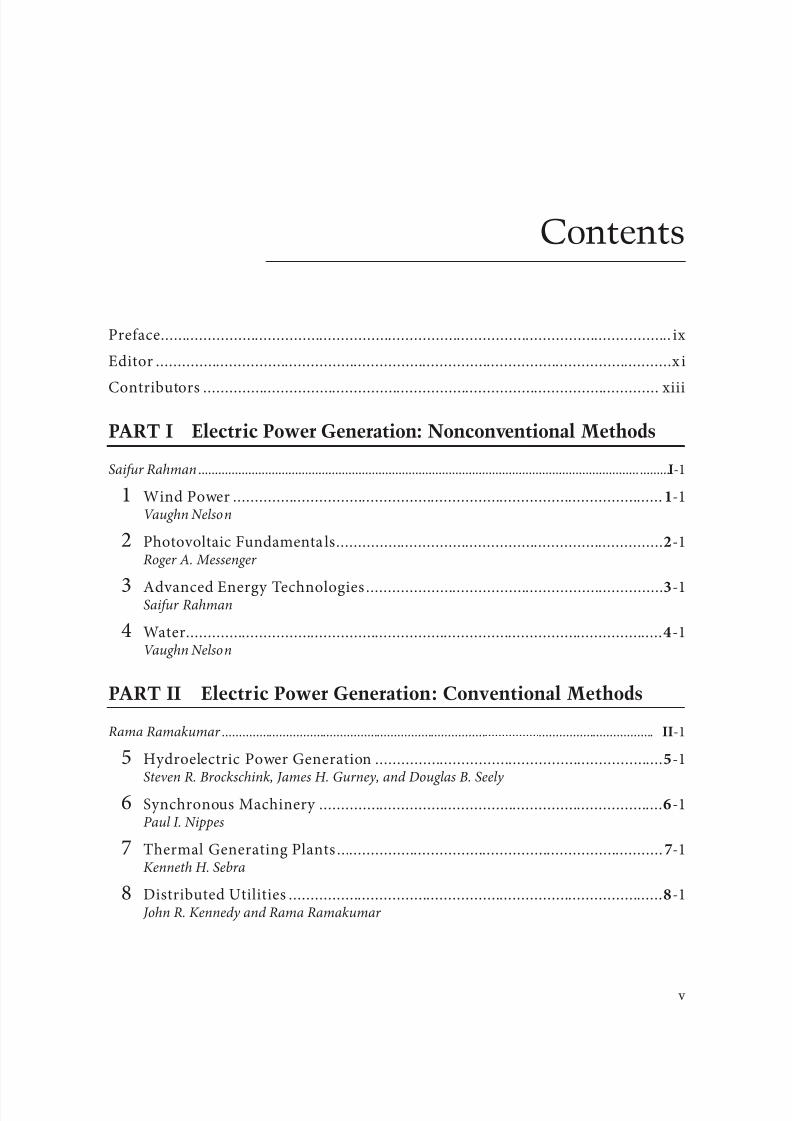
8102019 Power Handbook
httpslidepdfcomreaderfullpower-handbook 543
v
Contents
Preace ix
Editor x i
Contributors xiii
PART I Electric Power Generation Nonconventional Methods
Saiur Rahman -1
1 Wind Power -1Vaughn Nelson
2 Photovoltaic Fundamenta ls-1Roger A Messenger
3 Advanced Energy echnologies -1Saiur Rahman
4 Water -1Vaughn Nelson
PART II Electric Power Generation Conventional Methods
Rama Ramakumar -1
5 Hydroelectric Power Generation -1Steven R Brockschink James H Gurney and Douglas B Seely
6 Synchronous Machinery -1Paul I Nippes
7 hermal Generating Plants -1Kenneth H Sebra
8 Distributed Utilities -1 John R Kennedy and Rama Ramakumar
8102019 Power Handbook
httpslidepdfcomreaderfullpower-handbook 643
vi Contents
PART III Transmission System
George G Karady -1
9 Concept o Energy ransmission and Distribution -1
George G Karady 10 ransmission Line Structures -1
Joe C Pohlman
11 Insulators and Accessories -1George G Karady and Richard G Farmer
12 ransmission Line Construction and Maintenance-1 Jim Green Daryl Chipman and Yancy Gill
13 Insulated Power Cables Used in Underground Applications -1 Michael L Dyer
14 ransmission Line Parameters -1 Manuel Reta-Hernaacutendez
15 Sag and ension o Conductor -1Dale A Douglass and F Ridley Trash
16 Corona and Noise -1Giao N rinh
17 Geomagnetic Disturbances and Impacts upon Power System Operation -1 John G Kappenman
18 Lightning Protection -1William A Chisholm
19 Reactive Power Compensation -1Rao S Tallam and Geacuteza Jooacutes
20 Environmental Impact o ransmission Lines -1George G Karady
21 ransmission Line Reliability Methods -1Brian Keel Vishal C Patel and Hugh Stewart Nunn II
22 High-Voltage Direct Current ransmission System -1
George G Karady and Geacuteza Jooacutes 23 ransmission Line Structures -1
Robert E Nickerson Peter M Kandaris and Anthony M DiGioia Jr
24 Advanced echnology High-emperature Conductors -1 James R Hunt
8102019 Power Handbook
httpslidepdfcomreaderfullpower-handbook 743
viiContents
PART IV Distribution Systems
William H Kersting-1
25 Power System Loads -1
Raymond R Shoults and Larry D Swif 26 Distribution System Modeling and Analysis -1
William H Kersting
27 Power System Operation and Control -1George L Clark and Simon W Bowen
28 Hard to Find Inormation (on Distribution System Characteristicsand Protection) -1 Jim Burke
29 Real-ime Control o Distributed Generation -1
Murat Dilek and Robert P Broadwater
30 Distribution Short-Circuit Protection -1om A Short
PART V Electric Power Utilization
Andrew P Hanson -1
31 Metering o Electric Power and Energy -1 John V Grubbs
32 Basic Electric Power Utilization Loads Load Characterizationand Load Modeling -1 Andrew P Hanson
33 Electric Power Utilization Motors -1Charles A Gross
34 Linear Electric Motors -1 Jacek F Gieras
PART VI Power Quality
S Mark Halpin -1
35 Introduction -1S Mark Halpin
36 Wiring and Grounding or Power Quality -1Christopher J Melhorn
8102019 Power Handbook
httpslidepdfcomreaderfullpower-handbook 843
viii Contents
37 Harmonics in Power Systems -1S Mark Halpin
38 Voltage Sags -1 Math HJ Bollen
39 Voltage Fluctuations and Lamp Flicker in Power Systems -1S Mark Halpin
40 Power Quality Monitoring -1Patrick Coleman
8102019 Power Handbook
httpslidepdfcomreaderfullpower-handbook 943
ix
Preface
Te generation delivery and utilization o electric power and energy remain one o the most challeng-
ing and exciting 1047297elds o electrical engineering Te astounding technological developments o our age
are highly dependent upon a sae reliable and economic supply o electric power Te objective o the
Electric Power Engineering Handbook is to provide a contemporary overview o this ar-reaching 1047297eld
as well as a useul guide and educational resource or its study It is intended to de1047297ne electric powerengineering by bringing together the core o knowledge rom all o the many topics encompassed by
the 1047297eld Te chapters are written primarily or the electric power engineering proessional who seeks
actual inormation and secondarily or the proessional rom other engineering disciplines who wants
an overview o the entire 1047297eld or speci1047297c inormation on one aspect o it
Te 1047297rst and second editions o this handbook were well received by readers worldwide Based upon
this reception and the many recent advances in electric power engineering technology and applications
it was decided that the time was right to produce a third edition Because o the efforts o many indi-
viduals the result is a major revision Tere are completely new chapters covering such topics as FACS
smart grid energy harvesting distribution system protection electricity pricing linear machines In
addition the majority o the existing chapters have been revised and updated Many o these are major
revisionsTe handbook consists o a set o 1047297ve books Each is organized into topical parts and chapters in an
attempt to provide comprehensive coverage o the generation transormation transmission distribu-
tion and utilization o electric power and energy as well as the modeling analysis planning design
monitoring and control o electric power systems Te individual chapters are different rom most tech-
nical publications Tey are not journal-type articles nor are they textbooks in nature Tey are intended
to be tutorials or overviews providing ready access to needed inormation while at the same time pro-
viding sufficient reerences or more in-depth coverage o the topic
Tis book is devoted to the subjects o power system protection power system dynamics and stability
and power system operation and control I your particular topic o interest is not included in this list
please reer to the list o companion books reerred to at the beginning
In reading the individual chapters o this handbook I have been most avorably impressed by howwell the authors have accomplished the goals that were set Teir contributions are o course key to the
success o the book I grateully acknowledge their outstanding efforts Likewise the expertise and dedi-
cation o the editorial board and section editors have been critical in making this handbook possible o
all o them I express my proound thanks
Tey are as ollows
bull Nonconventional Power Generation Saiur Rahman
bull Conventional Power Generation Rama Ramakumar
bull ransmission Systems George G Karady
bull Distribution Systems William H Kersting
8102019 Power Handbook
httpslidepdfcomreaderfullpower-handbook 1043
x Preface
bull Electric Power Utilization Andrew P Hanson
bull Power Quality S Mark Halpin
bull ransormer Engineering (a complete book) James H Harlow
bull Substations Engineering (a complete book) John D McDonald
bull Power System Analysis and Simulation Andrew P Hanson
bull Power System ransients Pritindra Chowdhuribull Power System Planning (Reliability) Gerry Shebleacute
bull Power Electronics R Mark Nelms
bull Power System Protection Miroslav M Begovic
bull Power System Dynamics and Stability Prabha S Kundurdagger
bull Power System Operation and Control Bruce Wollenberg
I wish to say a special thank-you to Nora Konopka engineering publisher or CRC Pressaylor amp
Francis whose dedication and diligence literally gave this edition lie I also express my gratitude to the
other personnel at aylor amp Francis who have been involved in the production o this book with a spe-
cial word o thanks to Jessica Vakili Teir patience and perseverance have made this task most pleasant
Finally I thank my longtime riend and colleaguemdashMel Olken editor the Power and Energy
Magazinemdashor graciously providing the picture or the cover o this book
Arun Phadke or the 1047297rst and second editionsdagger Richard Farmer or the 1047297rst and second editions
8102019 Power Handbook
httpslidepdfcomreaderfullpower-handbook 1143
xi
Editor
received his BS and MS in electrical engi-
neering rom exas ech University Lubbock exas and his PhD rom
Oklahoma State University Stillwater Oklahoma He has taught electri-
cal engineering at exas ech University Oklahoma State University and
Virginia Polytechnic Institute and University He has been at AuburnUniversity since 1984 1047297rst as the Georgia power distinguished proessor
later as the Alabama power distinguished proessor and currently as pro-
essor emeritus o electrical engineering He also spent nine months dur-
ing 1990 at the University o okyo as the okyo Electric Power Company
endowed chair o electrical engineering His teaching interests are in net-
work analysis control systems and power engineering
During his teaching career Proessor Grigsby received 13 awards or teaching excellence Tese
include his selection or the university-wide William E Wine Award or eaching Excellence at Virginia
Polytechnic Institute and University in 1980 the ASEE Aamp Award or eaching Excellence in 1986
the 1988 Edison Electric Institute Power Engineering Educator Award the 1990ndash1991 Distinguished
Graduate Lectureship at Auburn University the 1995 IEEE Region 3 Joseph M Beidenbach OutstandingEngineering Educator Award the 1996 Birdsong Superior eaching Award at Auburn University and
the IEEE Power Engineering Society Outstanding Power Engineering Educator Award in 2003
Proessor Grigsby is a ellow o the Institute o Electrical and Electronics Engineers (IEEE) During
1998ndash1999 he was a member o the board o directors o IEEE as the director o Division VII or power
and energy He has served the institute in 30 different offices at the chapter section regional and inter-
national levels For this service he has received seven distinguished service awards such as the IEEE
Centennial Medal in 1984 the Power Engineering Society Meritorious Service Award in 1994 and the
IEEE Millennium Medal in 2000
During his academic career Proessor Grigsby has conducted research in a variety o projects related
to the application o network and control theory to modeling simulation optimization and control
o electric power systems He has been the major advisor or 35 MS and 21 PhD graduates With hisstudents and colleagues he has published over 120 technical papers and a textbook on introductory
network theory He is currently the series editor or the Electrical Engineering Handbook Series pub-
lished by CRC Press In 1993 he was inducted into the Electrical Engineering Academy at exas ech
University or distinguished contributions to electrical engineering
8102019 Power Handbook
httpslidepdfcomreaderfullpower-handbook 1243
8102019 Power Handbook
httpslidepdfcomreaderfullpower-handbook 1343
xiii
Contributors
Swedish ransmission Research Institute
Ludvika Sweden
Alabama Power Company
Birmingham Alabama
Department o Electrical Engineering
Virginia Polytechnic Institute and State
University
Blacksburg Virginia
Stantec Consulting
Portland Oregon
Quanta echnology
Raleigh North Carolina
Salt River Project
Phoenix Arizona
KinectricsUniversiteacute du Queacutebec agrave Chicoutimi
oronto Ontario Canada
Alabama Power Company
Birmingham Alabama
Alabama Power Company
Birmingham Alabama
DiGioia Gray and Associates LLC
Monroeville Pennsylvania
Electrical Distribution Design Inc
Blacksburg Virginia
Power Delivery Consultants Inc
Niskayuna New York
Salt River Project
Phoenix Arizona
School o Electrical Computer and Energy
Engineering
Arizona State University
empe Arizona
Department o Electrical Engineering
University o echnology and Lie Sciences
Bydgoszcz Poland
Salt River Project
Phoenix Arizona
8102019 Power Handbook
httpslidepdfcomreaderfullpower-handbook 1443
xiv Contributors
Salt River Project
Phoenix Arizona
Department o Electrical and ComputerEngineering
Auburn University
Auburn Alabama
Alabama Power Company
Birmingham Alabama
BC Hydro
Vancouver British Columbia Canada
Department o Electrical and Computer
Engineering
Auburn University
Auburn Alabama
Te Structure Group
Houston exas
Salt River Project
Phoenix Arizona
Department o Electrical and Computer
Engineering
McGill University
Montreal Quebec Canada
Salt River Project
Phoenix Arizona
Metatech Corporation
Duluth Minnesota
School o Electrical Computer and Energy
Engineering
Arizona State University
empe Arizona
Salt River Project
Phoenix Arizona
Georgia Power Company
Atlanta Georgia
Department o Electrical and ComputerEngineering
New Mexico State University
Las Cruces New Mexico
EPRI PEAC Corporation
Knoxville ennessee
Florida Atlantic University Boca Raton Florida
Alternative Energy Institute
West exas AampM University
Canyon exas
Consulting Engineer
Fort Worth exas
Magnetic Products and Services Inc
Holmdel New Jersey
Salt River Project
Phoenix Arizona
8102019 Power Handbook
httpslidepdfcomreaderfullpower-handbook 1543
xvContributors
Southern Caliornia Edison Company
Rosemead Caliornia
ConsultantPittsburgh Pennsylvania
Department o Electrical and Computer
Engineering
Virginia ech
Arlington Virginia
School o Electrical and Computer
EngineeringOklahoma State University
Stillwater Oklahoma
Electrical Engineering Academic Unit
Universidad Autoacutenoma de Zacatecas
Zacatecas Mexico
Baltimore Gas and Electric Company
Dameron Maryland
Stantec Consulting
Portland Oregon
Electric Power Research InstituteBurnt Hills New York
Department o Electrical Engineering
University o exas at Arlington
Arlington exas
f
Department o Electrical Engineering
University o exas at Arlington
Arlington exas
T
Salt River Project
Phoenix Arizona
y T
Southwire Company
Carrollton Georgia
Hydro-Queacutebec Institute o Research
Boucherville Quebec Canada
8102019 Power Handbook
httpslidepdfcomreaderfullpower-handbook 1643
34-1
Linear electric motors belong to the group o special electrical machines that convert electrical energy
directly into mechanical energy o translatory motion Linear electric motors can drive a linear-motion
load without intermediate gears screws or crank shafs Linear electric motors can be classi1047297ed as ollows
bull DC motorsbull Induction motors
bull Synchronous motors including reluctance and stepping motors
bull Oscil lating motors
bull Hybrid motors
Te application o DC linear motor is marginal Te most popular are permanent magnet (PM) linear
synchronous motors (LSMs) and linear induction motors (LIMs) which are manuactured commer-
cially in several countries and are 1047297nding many applications
A linear motor can be obtained by cutting a rotary motor along its radius rom the center axis o the
shaf to the external surace o the stator core and rolling it out 1047298at (Figure 341)
341 Linear Synchronous Motors3411 Basic Geometries and Constructions
An LSM is a linear motor in which the mechanical motion is in synchronism with the magnetic 1047297eld
ie the mechanical speed is the same as the speed o the traveling magnetic 1047297eld Te thrust (propulsion
orce) can be generated as an action o
bull raveling magnetic 1047297eld produced by a polyphase winding and an array o magnetic poles N
S hellip N S or a variable reluctance erromagnetic rail (LSMs with AC armature windings)
bull Magnetic 1047297eld produced by electronically switched DC windings and an array o magnetic poles N
S hellip N S or variable reluctance erromagnetic rail (linear stepping or switched reluctance motors)
34Linear Electric Motors
341 Linear Synchronous Motors -1Basic Geometries and Constructions bull Classi1047297cation bull Flux-
Switching PM Linear Motors bull Motors with Electromagnetic
Excitation bull Motors with Superconducting Excitation System
342 Linear Induction Motors -14
Basic Geometries and Constructions bullPropulsion o Wheel-on-Rail Vehicles
343 Variable Reluctance Motors -21344 Stepping Motors -22345 Switched Reluctance Motors -25346 Linear Positioning Stages -26Reerences -27
Jacek F GierasUniversity of Technology
and Life Sciences
8102019 Power Handbook
httpslidepdfcomreaderfullpower-handbook 1743
34-2 Electric Power Generation Transmission and Distribution
Te part producing the traveling magnetic 1047297eld is called the armature or orcer Te part that provides
the DC magnetic 1047298ux or variable reluctance is called the 1047297eld excitation system (i the excitation system
exists) or salient-pole rail reaction rail or variable reluctance platen Te terms primary and secondary
should rather be avoided as they are only justi1047297ed or LIMs [6] or transormers Te operation o an
LSM does not depend on which part is movable and which one is stationary
raditionally AC polyphase synchronous motors are motors with DC electromagnetic excitation the
propulsion orce o which has two components (1) due to the traveling magnetic 1047297eld and DC currentmagnetic 1047298ux (synchronous component) and (2) due to the traveling magnetic 1047297eld and variable reluc-
tance in d - and q-axes (reluctance component) Replacement o DC electromagnets with PMs is common
except or LSMs or magnetically levitated vehicles PM brushless LSMs can be divided into two groups
bull PM LSMs in which the input current waveorms are sinusoidal and produce a traveling magnetic
1047297eld
bull PM DC linear brushless motors (LBMs) with position eedback in which the input rectangular
or trapezoidal current waveorms are precisely synchronized with the speed and position o the
moving part
Construction o magnetic and electric circuits o LSMs belonging to both groups is the same LSMs can
be designed as 1047298at motors (Figure 342) or tubular motors (Figure 343) In DC brushless motors theinormation about the position o the moving part is usually provided by an absolute position sensor
Tis control scheme corresponds to an electronic commutation unctionally equivalent to the mechani-
cal commutation in DC commutator motors Tereore motors with square (trapezoidal) current wave-
orms are called DC brushless motors
Instead o DC or PM excitation the difference between the d - and q-axes reluctances and the traveling
magnetic 1047297eld can generate the reluctance component o the thrust Such a motor is called the AC vari-
able reluctance LSM Different reluctances in the d - and q-axes can be created by making salient erro-
magnetic poles using erromagnetic and nonerromagnetic materials or using anisotropic erromagnetic
materials Te operation o LBMs can be regarded as a special case o the operation o LSMs
1
1
2
2
x
x
v
v
z
z
y
(a)
(b)
y
0
0
1
1
2
2 x
xv
z z
v g
y y
0
0
1 2
21
y
v 0 x
z
d
g 1
g 2
x
z
y
v
0
Evolution o a rotary induction motor (a) solid-rotor induction motor into a 1047298at single-sided LIM
and (b) hollow-rotor induction motor into a 1047298at double-sided LIM 1 primary 2 secondary
8102019 Power Handbook
httpslidepdfcomreaderfullpower-handbook 1843
34-3Linear Electric Motors
In the case o LSMs operating on the principle o the traveling magnetic 1047297eld the speed v o the mov-
ing part is equal to synchronous speed v s ie
v v s= = =2 τ ω
πτ
(341)
Te synchronous speed v s o the traveling magnetic 1047297eld depends only on the input requency (angular
input requency ω = 2π ) and pole pitch τ It does not depend on the number o poles 2 p
As or any other linear-motion electrical machine the useul orce (thrust) F x is directly proportional
to the output power P out and inversely proportional to the speed v = v s ie
F
P
v x
out
s
=
(342)
Flat three-phase PM linear motors (Photo courtesy o Kollmorgen Radord VA)
ubular PM LSM Moving rod (reaction rail) contains circular PMs (Photo courtesy o Caliornia
Linear Drives Carlsbad CA)
8102019 Power Handbook
httpslidepdfcomreaderfullpower-handbook 1943
34-4 Electric Power Generation Transmission and Distribution
Direct electromechanical drives with LSMs or actory automation systems can achieve speeds exceeding
600 mmin = 36 kmh and acceleration o up to 360 ms2 [7] Te thrust density ie thrust per active sur-
ace 2 pτLi where Li is the effective width o the stack
F
p Lx
x
i
=2
(Nm2
τ)
(343)
o LSMs is higher than that o LIMs (Figure 344)
Te polyphase (usually three-phase) armature winding can be distributed in slots made in the orm
o concentrated-parameter coils or made as a coreless (air-cored) winding layer PMs are the most popu-
lar 1047297eld excitation systems or short traveling distances (less than 10 m) or example actory transporta-
tion or automation systems A long PM rail would be expensive Electromagnetic excitation is used in
high-speed passenger transportation systems operating on the principle o magnetic levitation (maglev)
Te German system ransrapid uses vehicle-mounted steel core excitation electromagnets and station-
ary slotted armatures Japanese MLX001 test train sets use onboard superconducting (SC) air-cored
electromagnets and a stationary three-phase air-cored armature winding distributed along the guide-
way (Yamanashi Maglev est Line)
3412 Classi1047297cation
LSMs can be classi1047297ed according to whether they are
bull Flat (planar) or tubular (cylindrical)
bull Single sided or double sided
bull Slotted or slotless
0
10000
20000
30000
40000
50000
60000
0 2000 4000 6000 8000 10000 12000 14000
Trust N
T h r u s t d e n s i t y N m 2
LSM OC
LSM WC
LSM AC
LSM NC
LIM NC
Comparison o thrust density or single-sided LIMs and LSMs AC air cooling NC natural cool-
ing OC oil cooling WC water cooling (From Gieras JF Status o linear motors in the United States International
Symposium on Linear Drives or Industry Applications (LDIArsquo03) Birmingham UK pp 169ndash176 2003)
8102019 Power Handbook
httpslidepdfcomreaderfullpower-handbook 2043
34-5Linear Electric Motors
bull Iron cored or air cored
bull ransverse 1047298ux or longitudinal 1047298ux
Te topologies mentioned earlier are possible or nearly all types o excitation systems LSMs operating
on the principle o the traveling magnetic 1047297eld can have the ollowing excitation systems
bull PMs in the reaction railbull PMs in the armature (passive reaction rail)
bull Electromagnetic excitation system (with winding)
bull SC excitation system
bull Passive reaction rail with saliency and neither PMs nor windings (variable reluctance motors)
LSMs with electronically switched DC armature windings are designed either as linear stepping motors
or linear switched reluctance motors
34121 PM Motors with Active Reaction Rail
Figure 345a shows a single-sided 1047298at LSM with the armature winding located in slots and surace PMs
Figure 345b shows a similar motor with buried-type PMs In surace arrangement o PMs the yoke(back iron) o the reaction rail is erromagnetic and PMs are magnetized in the normal direction (per-
pendicular to the active surace) Buried PMs are magnetized in the direction o the traveling magnetic
1047297eld and the yoke is nonerromagnetic or example made o aluminum (Al) Otherwise the bottom
leakage 1047298ux would be greater than the linkage 1047298ux as shown in Figure 346 Te same effect occurs in
buried-type PM rotors o rotary machines in which the shaf must also be nonerromagnetic [239]
Te so-called Halbach array o PMs also does not require any erromagnetic yoke and excites stronger
magnetic 1047298ux density and closer to the sinusoids than a conventional PM array Te key concept o the
Halbach array is that the magnetization vector should rotate as a unction o distance along the array
(Figure 347)
It is recommended that a PM LSM be urnished with a damper A rotary synchronous motor has a cage
damper winding embedded in pole shoe slots When the speed is different rom the synchronous speed
electric currents are induced in damper circuits Te action o the armature magnetic 1047297eld and damper
currents allows or asynchronous starting damps the oscillations and helps to return to synchronous
operation when the speed decreases or increases Also a damper circuit reduces the backward-traveling
magnetic 1047297eld It would be rather difficult to urnish PMs with a cage winding so that the damper o PM
LSMs has the orm o an Al cover (Figure 348a) or solid steel pole shoes (Figure 348b) In addition steel
pole shoes or Al cover (shield) can protect brittle PMs against mechanical damage
Te detent orce ie attractive orce between PMs and the armature erromagnetic teeth orce ripple
and some higher-space harmonics can be reduced with the aid o skewed assembly o PMs Skewed PMs
can be arranged in one row (Figure 349a) two rows (Figure 349b) or even more rows
1 3
(a) (b)
N
S
τ τ
S
N
1 2 3
N S
τ τ
S N
Single-sided 1047298at PM LSMs with slotted armature core and (a) surace PMs and (b) buried PMs
1 PM 2 mild steel pole 3 yoke
8102019 Power Handbook
httpslidepdfcomreaderfullpower-handbook 2143
34-6 Electric Power Generation Transmission and Distribution
(a)
(b)
Magnetic 1047298ux distribution in the longitudinal sections o buried-type PM LSMs (a) nonerromag-
netic yoke and (b) erromagnetic yoke (back iron)
1
2
Double-sided LSM with Halbach array o PMs 1 PMs 2 coreless armature winding
2
2
3(a)
(b)
3
1
1
Dampers o surace-type PM LSMs (a) Al cover (shield) and (b) solid steel pole shoes 1 PM
2 damper 3 yoke
8102019 Power Handbook
httpslidepdfcomreaderfullpower-handbook 2243
34-7Linear Electric Motors
Speci1047297cation data o 1047298at single-sided PM LBMs manuactured by Anorad are shown in able 341 [1]
and motors manuactured by Kollmorgen are shown in able 342 [11] Te temperature 25degC 125degC
or 130degC or the thrust current resistance and power loss is the temperature o the armature winding
Te electromotive orce (EMF) constant kE in ables 341 and 342 or sinusoidal operation is de1047297ned
according to the equation expressing the EMF (induced voltage) excited by PMs without the armature
reaction ie
E k v E s=
(344)
where v s is the synchronous speed according to Equation 341 Tus the armature constant kE multiplied
by the synchronous speed v s gives the EMF E
S SN N N N N N
N N N N N N
N N N N N N
S S S S
S S S S S S
S
(b)
(a)
S S S S S
Skewed PMs in 1047298at LSMs (a) one row and (b) two rows
Flat Tree-Phase Single-Sided PM LBMs with Natural Cooling Systems
Manuactured by Anorad Hauppauge NY
Parameter LCD--1 LCD--2-P LCD--3-P LCD--4-P
Continuous thrust at 25degC N 163 245 327 490
Continuous current at 25degC A 42 63 85 127
Continuous thrust at 125degC N 139 208 277 416
Continuous current at 125degC A 36 54 72 108
Peak thrust (025 s) N 303 455 606 909
Peak current (025 s) A 92 138 184 276
Peak orce (10 s) N 248 373 497 745
Peak current (10 s) A 73 110 147 220Continuous power losses at 125degC W 58 87 115 173
Armature constant kE Vsm 129
Trust constant (three phases) kF NA 386
Resistance per phase at 25degC Ω 32 22 16 11
Inductance mH 143 95 71 48
PM pole pitch mm 2345
Maximum winding temperature degC 125
Armature assembly mass kg 18 24 36 48
PM assembly mass kgm 64
Normal attractive orce N 1036 1555 2073 3109
8102019 Power Handbook
httpslidepdfcomreaderfullpower-handbook 2343
34-8 Electric Power Generation Transmission and Distribution
Te thrust constant kF in ables 341 and 342 is de1047297ned according to the simpli1047297ed equation or the
developed electromagnetic thrust ie
F k I dx F a= cos Ψ
(345)
or a sinusoidally excited LSM with equal reluctances in the d - and q-axes and or the angle between the
armature current I a and the q-axis Ψ = 0deg (cos Ψ = 1) Tus the thrust constant kF times the armature
current I a gives the electromagnetic thrust developed by the LSM
Double-sided 1047298at PM LSMs consist o two external armature systems and one internal excitation sys-
tem (Figure 3410a) or one internal armature system and two external excitation systems (Figure 3410b)
In the second case a linear Grammersquos armature winding can be used
In slotless motors the primary winding is uniormly distributed on a smooth armature core or does
not have any armature core Slotless PM LSMs are detent orcendashree motors provide lower torque ripple
and at high input requency can achieve higher efficiency than slotted LSMs On the other hand larger
nonerromagnetic air gap requires more PM material and the thrust density (thrust per mass or volume)
is lower than that o slotted motors (able 343) Te input current is higher as synchronous reactances
Flat Tree-Phase Single-Sided PM LBMs with Natural Cooling Systems
Manuactured by Kollmorgen Radord VA
Parameter IC11-030 IC11-050 IC11-100 IC11-200
Continuous thrust at 130degC N 150 275 600 1260
Continuous current at 130degC A 40 44 48 50
Peak thrust N 300 500 1000 2000
Peak current A 79 79 79 79
Continuous power losses at 130degC W 64 106 210 418
Armature constant at 25degC kE Vsm 309 514 1028 2057
Trust constant (three phases) at 25degC kF NA 378 629 1259 2519
Resistance line to line at 25degC Ω 19 26 44 80
Inductance line to line mH 173 278 541 1066
Electrical time constant ms 89 105 123 134
Termal resistance winding to external
structure degCW
164 099 050 025
Maximum winding temperature degC 130
Armature assembly mass kg 20 32 62 122PM assembly mass kgm 55 76 128 269
Normal attractive orce N 1440 2430 4900 9850
(a)
N S N SN S N S
N S N SN S N S
(b)
Double-sided 1047298at PM LSMs with (a) two external armature systems and (b) one internal armature
system
8102019 Power Handbook
httpslidepdfcomreaderfullpower-handbook 2443
34-9Linear Electric Motors
in the d - and q-axes can decrease to a low undesired value due to the absence o teeth Figure 3411a
shows a single-sided 1047298at slotless motor with armature core and Figure 3411b shows a double-sided slot-
less motor with inner air-cored armature winding (moving coil motor)
able 344 contains perormance speci1047297cations o double-sided PM LBMs with inner three-phase air-
cored armature winding manuactured by rilogy Systems Corporation Webster X (Figure 3412)
N
(a) (b)
S N S N S N S
S N NS
Flat slotless PM LSMs (a) single-sided with armature core and (b) double-sided with inner air-
cored armature winding
Slotted versus Slotless LSMs
Quantity Slotted LSM Slotless LSM
Higher thrust density X
Higher efficiency in the lower speed range X
Higher efficiency in the higher speed range x
Lower input current X
Less PM material X
Lower winding cost x
Lower thrust pulsations x
Lower acoustic noise x
Flat Double-Sided PM LBMs with Inner Tree-Phase Air-Cored Series-Coil
Armature Winding Manuactured by rilogy Systems Corporation Webster X
Parameter 310-2 310-4 310-6
Continuous thrust N 1112 2091 3149
Continuous power or sinusoidal operation W 87 152 230
Peak thrust N 356 712 1068
Peak power W 900 1800 2700
Peakcontinuous current A 10028 10026 10026
Trust constant kF or sinusoidal operation NA 400 800 1200
Trust constant kF or trapezoidal operation with Hallsensors NA
351 725 1095
Resistance per phase Ω 86 172 258
Inductance plusmn05 mH 60 120 180
Heat dissipation constant or natural cooling WdegC 110 201 301
Heat dissipation constant or orced air cooling WdegC 130 240 355
Heat dissipation constant or liquid cooling WdegC 154 285 421
Number o poles 2 4 6
Coil length mm 1422 2642 3861
Coil mass kg 055 103 153
Mass o PM excitation systems kgm 1267 or 838
8102019 Power Handbook
httpslidepdfcomreaderfullpower-handbook 2543
34-10 Electric Power Generation Transmission and Distribution
By rolling a lat LSM around the axis parallel to the direction o the traveling magnetic ield
ie parallel to the direction o thrust a tubular (cylindrical) LSM can be obtained (Figure 3413) A
tubular PM LSM can also be designed as a double-sided motor or slotless motor
ubular single-sided LSMs LinMoreg with movable internal PM excitation system (slider) and stationaryexternal armature are manuactured by Sulzer Electronics AG Zurich Switzerland (able 345) All active
motor parts bearings position sensors and electronics have been integrated into a rigid metal cylinder [14]
LinMotreg is a registered trademark o Sulzer Electronics AG Zuumlrich Switzerland
(b)(a)
N S N S N S
N S N S N S
N S N S
SNN S
Single-sided slotted tubular PM LSMs (a) with external armature system and (b) with external
excitation system
Data o ubular LSMs LinMotreg Manuactured by Sulzer Electronics AG Zuumlrich Switzerland
Parameter P01 23 times 80 P01 23 times 160 P01 37 times 120 P01 37 times 240
Number o phases 2
PMs NdFeB
Maximum stroke m 0210 0340 1400 1460Maximum orce N 33 60 122 204
Maximum acceleration ms2 280 350 247 268
Maximum speed ms 24 42 40 31
Stator (armature) length m 0177 0257 0227 0347
Stator outer diameter mm 23 23 37 37
Stator mass kg 0265 0450 0740 1385
Slider diameter mm 12 12 20 20
Maximum temperature o the armature winding degC 90
Flat double-sided PM LSM with inner moving coil (Photo courtesy o rilogy Systems Webster X)
8102019 Power Handbook
httpslidepdfcomreaderfullpower-handbook 2643
34-11Linear Electric Motors
All the aorementioned PM LSMs are motors with longitudinal magnetic 1047298ux the lines o which lie
in the plane parallel to the direction o the traveling magnetic 1047297eld LSMs can also be designed as trans-
verse magnetic 1047298ux motors in which the lines o magnetic 1047298ux are perpendicular to the direction o the
traveling 1047297eld Figure 3414a shows a single-sided transverse 1047298ux LSM in which PMs are arranged in two
rows A pair o parallel PMs creates a two pole 1047298ux excitation system A double-sided con1047297guration o
transverse 1047298ux motor is possible however it is complicated and expensive (Figure 3414b)
34122 PM Motors with Passive Reaction Rail
Te drawback o PM LSMs is the large amount o PM material that must be used to design the excitation
system Normally expensive rare-earth PMs are requested I a small PM LSM uses say 10 kg o NdFeB
per 1 m o the reaction rail and 1 kg o good-quality NdFeB costs US$ 130 the cost o the reaction rail
without assembly amounts to US$ 1300 per 1 m Tis price cannot be acceptable or example in pas-
senger transportation systems
A cheaper solution is to apply the PM excitation system to the short armature that magnetizes the
long reaction rail and creates magnetic poles in it Such a linear motor is called the homopolar LSM
Te homopolar LSM as described in [517] is a double-sided AC linear motor that consists o two
polyphase armature systems connected mechanically and magnetically by a erromagnetic U-type yoke
(Figure 3415) Each armature consists o a typical slotted linear motor stack with polyphase armature
winding and PMs located between the stack and U-type yoke Since the armature and excitation systems
are combined together the armature stack is oversized as compared with a conventional steel-cored LSM
Te PMs can also be replaced by electromagnets [1719] Te variable reluctance reaction rail is passive
Te saliency is created by using erromagnetic (solid or laminated) cubes separated by a nonerromag-netic material Te reaction rail poles are magnetized by the armature PMs through the air gap Te trav-
eling magnetic 1047297eld o the polyphase armature winding and salient poles o the reaction rail produce the
thrust Such a homopolar LSM has been proposed or the propulsion o maglev trains o Swissmetro [17]
Further simpli1047297cation o the double-sided con1047297guration can be made to obtain a single-sided PM
LSM shown in Figure 3416
3413 Flux-Switching PM Linear Motors
Large gantry systems and machining centers require powerul linear motors preerably with PM-ree
reaction rail Siemens 1FN6 PM LSMs with a magnet-ree reaction rail belong to the group o the so
5
(a) (b)
5
N S
N
N
3
4
4
3
2
6
1
3
6
1
6
1
i
S
2
2
N
N
SNN
S
ransverse 1047298ux PM LSM (a) single-sided and (b) double-sided 1 armature winding 2 armature
laminated core 3 PM 4 back erromagnetic core 5 magnetic 1047298ux 6 armature current
8102019 Power Handbook
httpslidepdfcomreaderfullpower-handbook 2743
34-12 Electric Power Generation Transmission and Distribution
called 1047298ux-switching PM machines [1016] Te armature system is air cooled degree o protection IP23
class o insulation F line voltage rom 400 to 480 V rated thrust rom 235 to 2110 N maximum veloc-
ity at rated thrust rom 170 to 540 mmin (able 346) overload capacity 38 o rated thrust modular
type construction [20] Tese LSMs operate with Siemens Sinamics or Simodrive solid-state converters
and external encoders According to Siemens [20] these new LSMs produce thrust orces and velocities
equivalent to competitive classical models or light-duty machine tool machine accessory and material
handling applications
2 3 244 1
N
S
S
N
N
S
S
N
5
Single-sided PM LSM with a passive reaction rail 1 PM 2 armature winding 3 armature stack
4 yoke 5 erromagnetic reaction rail
1
1
2 343
5
Fe Fe Fe Fe
Double-sided homopolar PM LSM with passive reaction rail 1 PM 2 armature winding
3 armature stack 4 yoke 5 reaction rail
Speci1047297cations o 1FN6 PM LSMs Manuactured by Siemens Erlangen Germany
Armature Unit Rated Trust N Max Trust N
Max Speed at
Rated Trust
mmin
Max Speed at
Max Trust
mmin
Rated
Current A Max Current A
1FN6008-1LC17 235ndash350 900 263 103 17ndash26 90
1FN6008-1LC37 235ndash350 900 541 224 35ndash53 180
1FN6016-1LC30 470ndash710 1800 419 176 54ndash80 280
1FN6016-1LC17 935ndash1400 3590 263 101 70ndash105 360
1FN6024-1LC12 705ndash1060 2690 176 69 35ndash53 180
1FN6024-1LC20 705ndash1060 2690 277 114 54ndash80 280
1FN6024-1LG10 2110ndash3170 8080 172 62 105ndash160 540
1FN6024-1LG17 2110ndash3170 8080 270 102 162ndash243 840
Source Synchronous Linear Motor 1FN6 Te Electrical Gear Rack Siemens AG Industry Sector Drive echnologies
Motion Control Erlangen Germany 2008
8102019 Power Handbook
httpslidepdfcomreaderfullpower-handbook 2843
34-13Linear Electric Motors
Te magnet-ree reaction rail is easy to install and does not require the saety considerations o stan-
dard PM reaction rails Without PMs there is no problem with errous chips and other debris beingattracted to these sections Maintenance becomes a simple matter o installing a wiper or brush on the
moving part o the slide
Te 1047298ux-switching LSM comprises an armature section that is equipped with coils and PMs as well
as a nonmagnetic toothed reaction rail section (Figure 3417) Te key design innovation is an LSM in
which PMs are integrated directly into the lamination o the armature core along with the individual
windings or each phase Both magnitudes and polarities o the linkage 1047298ux in the armature winding
vary periodically along with the reaction rail movement Te magnetic 1047298ux between the armature core
and steel reaction rail is controlled by switching the three-phase armature currents according to a desig-
nated algorithm Te passive reaction rail consists o milled steel with poles (teeth) and is much simpler
to manuacture
3414 Motors with Electromagnetic Excitation
Te electromagnetic excitation system o an LSM is similar to the salient-pole rotor o a rotary
synchronous motor Figure 3418 shows a 1047298at single-sided LSM with salient erromagnetic poles and
DC 1047297eld excitation winding Te poles and pole shoes can be made o solid steel laminated steel or sin-
tered powder I the electromagnetic excitation system is integrated with the moving part the DC cur-
rent can be delivered with the aid o brushes and contact bars inductive power transer (IP) systems
linear transormers or linear brushless exciters
A AB BC C
1
2
3
4
5
v
τ2
τ1
Construction o 1047298ux-switching LSM with PM-ree reaction rail 1 laminated armature core
2 PM 3 armature coil (phase C) 4 toothed passive steel reaction rail 5 linkage magnetic 1047298ux (phase A is on)
1
3
τ τ
2
S
d d q q q
4
N
Electromagnetic excitation system o a 1047298at single-sided iron-cored LSM 1 salient pole 2 DC
excitation winding 3 erromagnetic rail (yoke) 4 armature system
8102019 Power Handbook
httpslidepdfcomreaderfullpower-handbook 2943
34-14 Electric Power Generation Transmission and Distribution
LSMs with electromagnetic excitation (wound-1047297eld reaction rail) are used in German ransrapid
maglev train (Figure 3419)
3415 Motors with Superconducting Excitation System
In large-power LSMs the electromagnets with erromagnetic core that produce the excitation 1047298ux can
be replaced by coreless SC electromagnets Since the magnetic 1047298ux density produced by the SC electro-
magnet is greater than the saturation magnetic 1047298ux density o the best laminated alloys ( Bsat asymp 24 or
cobalt alloy) there is no need to use the armature erromagnetic core An LSM with SC 1047297eld excitation
system is a totally air-cored machine (Figure 3420)
Experimental maglev trains on the Yamanashi Maglev est Line (YML) in Yamanashi Preecture(west rom okyo) Japan are driven by air-cored LSMs with SC excitation systems ( Figure 3421)
342 Linear Induction Motors
LIMs have ound the widest prospects or applications in transportation systems beginning with electri-
cal traction on small passenger or material supply cars (used at airports exhibitions electrohighways
elevators) and ending with pallet transportation waer transportation belt conveyors transportation
systems o bulk materials etc Te second important place or LIM applications is in industry ie man-
uacturing processes (machine tools hammers presses mills separators automated manuacturing systems
strip tensioners textile shuttles index tables turntables disk saws or wood sliding doors robots etc)
ransrapid 09 maglev train driven by LSMs with electromagnetic excitation (Photo courtesy oTyssen ransrapid System GmbH Munich Germany)
1
2A
B
C B
A
A
C
S SN
τ τ τ τ τ
N N
CBA
Tree-phase air-cored LSM with SC excitation system 1 armature coils 2 SC excitation coils
8102019 Power Handbook
httpslidepdfcomreaderfullpower-handbook 3043
34-15Linear Electric Motors
LIMs can also play an important part in industrial investigations and tests or example high acceleration
o model aircraf in aerodynamic tunnels high acceleration o vessels in laboratory pools propulsion o
mixers shakers and vibrators and adjusting xndashy tables and instruments Tere is also a possibility o
using LIMs in consumer electronics (sound and vision equipment knitting machines curtains) and in
offices (transportation o documents letters and cash) Te Handbook o Linear Motor Applications [21]
printed in Japan in 1986 contains about 50 examples o applications o LIMs in operation or in the pro-
cess o implementation
3421 Basic Geometries and Constructions
A LIM can be obtained by cutting in the same way either a cage rotor induction motor or a wound rotor
induction motor Te stator becomes the primary and the rotor becomes the secondary [12] Te secondary
o a LIM can be simpli1047297ed by using a solid steel core and replacing the cage (ladder) or slip-ring winding with
a high-conductivity nonerromagnetic plate (Al or Cu) Te nonerromagnetic plate is a secondary electric
circuit with distributed parameters and the erromagnetic core is a conductor both or the magnetic 1047298ux
and the electric current It does not matter rom the principle o operation point o view which part (primary
or secondary) is in motion Tus the 1047298at single-sided LIM can be obtained rom a solid rotor induction
motor (Figure 341a) and the 1047298at double-sided LIM can be obtained rom a hollow-rotor induction motor
with wound external and internal stator (Figure 341b) In a double-sided LIM the secondary erromagneticcore is not necessary since the magnetic 1047298ux excited by one o the primary windings afer passing through
the air gaps and nonerromagnetic secondary is then closed up by the core o the second primary unit
Teoretically a double-sided LIM with primary windings located on two cores in comparison with a
single-sided LIM exciting the same MMF has twice the air gap magnetic 1047298ux density Tereore the thrust
o such a motor is our times greater assuming the same dimensions I only one primary core is wound
the output parameters o a double-sided LIM are the same as those or a single-sided LIM with laminated
secondary back iron Te undamental advantage o double-sided LIMs is the elimination o the normal
attractive orce between the primary and the secondary because the secondary is usually nonerromagnetic
Flat LIMs can have primary cores consisting o an array o cores arranged in parallel at appropri-
ate distances and connected magnetically by additional yokes perpendicular to the direction o the
YML in Yamanashi Preecture (near okyo) Japan YML maglev trains use air-cored LSMs
with SC excitation system (Photo courtesy o Central Japan Railway Company and Railway echnical Research
Institute okyo Japan)
8102019 Power Handbook
httpslidepdfcomreaderfullpower-handbook 3143
34-16 Electric Power Generation Transmission and Distribution
traveling 1047297eld A magnetic circuit designed in such a way makes it possible to apply two windings in
general multiphase windings with perpendicular conductors as shown in Figure 3422 Adjusting the
current in each winding the secondary can be moved in two perpendicular directions and can be posi-
tioned at any point o the xndashy plane A 1047298at LIM with two degrees o reedom (DOFs) can be designed both
as single-sided and double-sided machines
By rolling a 1047298at single-sided or double-sided LIM around the axis parallel to the direction o the travel-
ing magnetic 1047297eld ie parallel to the direction o the thrust a tubular motor can be obtained (Figure 3423)
A tubular (cylindrical) LIM similar to a 1047298at LIM can be designed both as single-sided and double-
sided machines and can have a square or rectangular cross section as in Figure 3424 Tere are possible
Te primary o a 1047298at LIM with two DOFs
g
g
g 1
g 2
(c)
(b)
(a)
d
v
v
v
1
1
1 1
1
1
2
2
2
2
2
2
ubular LIMs (a) single-sided with an external short primary (b) single-sided with an external
short secondary and (c) double-sided with short primary 1 primary 2 secondary
8102019 Power Handbook
httpslidepdfcomreaderfullpower-handbook 3243
34-17Linear Electric Motors
con1047297gurations other than that in Figure 3423 regarding the length o the secondary with respect to thelength o the primary
All the aorementioned LIMs are motors with longitudinal magnetic 1047298ux ie the lines o magnetic
1047298ux lie in the plane parallel to the direction o the traveling magnetic 1047297eld A LIM can also be designed
in such a way as to obtain magnetic 1047298ux lines perpendicular to the direction o the traveling 1047297eld Such
motors are said to have transverse magnetic 1047298ux (Figure 3425)
Te undamental advantage o a LIM with transverse magnetic 1047298ux in comparison with a LIM with
longitudinal magnetic 1047298ux is the lower magnetizing current necessary due to the shorter magnetic 1047298ux
paths Te signi1047297cant disadvantage is lower thrust A 1047298at LIM with transverse magnetic 1047298ux usually has
a primary winding o concentrated coils located on salient poles
A 1047298at single-sided LIM with transverse 1047298ux can produce not only thrust but also electrodynamic
suspension In the design shown in Figure 3426 the secondary is suspended electrodynamically andpropelled and stabilized laterally by the primary magnetic 1047297eld [8] Te primary magnetic circuit con-
sists o E-shaped laminations assembled in two rows Te short secondary is made o light Al alloy in the
orm o a boat Te lateral sides o the boat are inclined by 60deg with respect to the active surace Such a
shape provides maximum normal repulsive orce and maximum lateral stabilization
According to their geometry the LIMs can be divided into the ollowing groups
bull With movable primary or movable secondary
bull Single sided and double sided
bull Flat and tubular
bull With short primary and short secondary
bull With longitudinal and transverse magnetic 1047298ux
1 2 3 4 1 2 3 4
ubular double-sided LIM with a square cross section 1 primary 2 secondary 3 primary coil
4 internal core
v
v
1 1
1
1
(a)
(b)
22
22
Flat LIM with transverse magnetic 1047298ux and salient poles (a) single-sided and (b) double-sided
1 primary 2 secondary
8102019 Power Handbook
httpslidepdfcomreaderfullpower-handbook 3343
34-18 Electric Power Generation Transmission and Distribution
Te linear speed o a LIM is
v s v s= minus( )1 (346)
where
s is the slip
v s is the synchronous speed according to Equation 341
Neglecting the longitudinal end effect [6] the electromagnetic thrust developed by a LIM can be
expressed in a similar way as or a rotary induction motor ie
F
m
v I
R
sdx
s
= prime( ) prime1
2
2 2
(347)
where
m1 is the number o phases o the primary winding
v s is the synchronous speed according to Equation 341
primeI 2 is the secondary current reerred to the primary system
primeR2 is the secondary resistance reerred to the primary system
s is the slip
Te secondary resistance primeR2 must include the so-called edge effect [6]
3422 Propulsion of Wheel-on-Rail Vehicles
Modern railway systems and electrical traction should meet the ollowing requirements
bull High level o automatization and computerization
bull Propulsion and braking independent o adhesion which in turn is affected 1047297rst o all by climate
and weather
bull Low level o noise sometimes below 70 dB (A)
Flat LIM with transverse magnetic 1047298ux salient poles and nonerromagnetic secondary pro-
pelled suspended and stabilized electrodynamically (From Gieras JF et al Analytical calculation o electro-
dynamic levitation orces in a special-purpose linear induction motor International Electric Machines and Drives
Conerence (IEMDCrsquo11) Niagara Falls Ontario Canada 2011 [on CD-ROM])
8102019 Power Handbook
httpslidepdfcomreaderfullpower-handbook 3443
34-19Linear Electric Motors
bull Ability to cope with high slopes at least 6 and sharp bends with radius o curvature less than 20 m
bull No pollution to natural environment and landscape
bull High reliability
Te congestion problems o big cities should be solved by creating collective transport orms that can be
implemented without affecting a highly populated city For example there are many cities in Italy where
the historical center has remained the same since the Renaissance A heavy railway might be a com-
pletely wrong solution and have a notable impact on the city planning An adequate solution might be
a light railway a people mover with transport capacity o 10000ndash20000 passengers per hour to replace
the traditional transport nets and to integrate the existing railway nets
All the requirements mentioned earlier can be met by using LIMs as propulsion machines Replacing
electrical rotary motors with linear motors in traction drives (electrical locomotives) generally does
not require new tracks but only their adjustment to linear drives Single-sided LIMs (Figure 3427a and b)
are best since the normal attractive orce o these can strengthen the adhesion o wheels and rails
Te air gap is rom 10 to 15 mm Most requently the motor car has two LIMs with short primaries
(Figure 3427a) assembled in series Te double-layer secondary consists o a solid back iron and an Al
cap and is located between the rails Cables or computer communication with the vehicle and quite
ofen collectors or electrical energy delivery to the vehicle are located along the track Tree-phaseLIMs are ed rom variable-voltage variable-requency (VVVF) voltage-source inverters A linear pro-
pulsion system o wheel-on-rail vehicles allows more 1047298exibility (Figure 3428) reducing noise on bends
and wear o the wheels and rails
Double-sided LIMs (Figure 3427c and d) have ound very limited application due to the technical
difficulty o eliminating aults caused by bends in the secondary with primary cores on either side It is
more difficult to keep a small and uniorm air gap in double-sided LIMs than that in single-sided LIMs
Te LIM-driven wheel-on-rail vehicles are built or low velocities ie less than 100 kmh and or
short routes ie less than 50 km (urban transit systems and short-distance trains) At present LIM-
driven trains operate in oronto and Vancouver BC Canada in Detroit MI (Figure 3429) okyo
(Figure 3430) and Osaka Japan and Kuala Lumpur Malaysia
(a) (b)
(c) (d)
LIM-driven wheel-on-rail cars (a) single-sided LIM with short primary mounted on the undercar-
riage (b) single-sided LIM with short secondary mounted on the undercarriage (c) double-sided LIM with short pri-
mary mounted on the undercarriage and (d) double-sided LIM with short secondary mounted on the undercarriage
8102019 Power Handbook
httpslidepdfcomreaderfullpower-handbook 3543
34-20 Electric Power Generation Transmission and Distribution
(a) (b)
Te undercarriage o a wheel-on-rail vehicle (a) rotary motor propulsion and (b) LIM propulsion
Detroit people mover driven by single-sided LIMs
oei Oedo subway line in okyo driven by single-sided LIMs
8102019 Power Handbook
httpslidepdfcomreaderfullpower-handbook 3643
34-21Linear Electric Motors
Te design data o some single-sided traction LIMs are presented in able 347 and double-sided trac-
tion LIMs in able 348
343 Variable Reluctance Motors
Te simplest construction o a variable reluctance LSM or linear reluctance motor (LRM) is that shown
in Figure 3418 with DC excitation winding being removed However the thrust o such a motor wouldbe low as the ratio o d -axis permeance to q-axis permeance is low Better perormance can be obtained
when using 1047298ux barriers [18] or steel laminations [15] o make 1047298ux barriers any nonerromagnetic
materials can be used o obtain high permeance (low reluctance) in the d -axis and low permeance in
the q-axis steel laminations should be oriented in such a way as to create high permeance or the d -axis
magnetic 1047298ux
Figure 3431a shows a variable reluctance platen with 1047298ux barriers and Figure 3431b shows how to
arrange steel laminations to obtain different reluctances in the d - and q-axes Te platen can be com-
posed o segments the length o which is equal to the pole pitchτ Each segment consists o semicircular
lamellas cut out rom electrotechnical sheet A 1047297lling or example epoxy resin is used to make the seg-
ment rigid and robust By putting the segments together a platen o any desired length can be obtained
Design Data o Single-Sided Tree-Phase LIMs or Propulsion o Vehicles
Quantity
LIM
UnitJLMDR ICS KU CIGG GEC
Pullout thrust at requency given
in the ollowing F x
125 90 35 17 07 kN
Input requency 200 400 250 400 600 Hz
Rated phase current V 1 2750 4650 1300 2000 2000 A
Number o poles 2 p 8 6 4 6 4 mdash
Number o turns per phase N 1 128 96 128 108 48 mdash
Equivalent diameter o conductor d 1 mdash 893 528 1115 81 mm
Number o parallel conductors mdash 1 mdash 19 1 mdash
Effective width o primary core Li 023 0216 029 0101 01715 m
Pole pitch τ 027 02868 030 025 020 m
Length o single end connection l e mdash 03483 mdash 02955 03685 m
Coil pitch wc 0225 01673 025 01944 01555 m
Air gap g 150 126 120 150 182 mm
Number o slots z 1( primez 1) 96(106) 72(79) 48(58) 54(61) 36(43) mdash
Width o slot b11 mdash 156 170 150 1308 mm
Width o slot opening b14 mdash 156 mdash 1044 1308 mm
Depth o slot h11 mdash 530 380 3421 6147 mm
Height o yoke h1 y mdash 436 393 7163 500 mm
Conductivity o back iron at 20degC σFe mdash 446 952 446 512 times106 Sm
Conductivity o Al cap at 20degC σ Al mdash 300 303 323 215 times106 Sm
Width o back iron w 03 024 03 0111 01715 m
Tickness o back iron hsec 190 125 250 254 474 mm
Tickness o Al cap d 50 45 50 45(25) 32 mm
Tickness o Al cap behind Fe core t ov 50 170 50 127 32 mm
Width o Al cap 030 032 040 0201 02985 m
JLMDR Japanese Linear Motor Driven Railcar Japan ICS Intermediate Capacity ransit System Canada KU
Kyushu University LIM Japan CIGG Canadian Inst o Guided Ground ransport Canada GEC General
Electric Company United States (z 1 ) is the number o hal 1047297lled slots
8102019 Power Handbook
httpslidepdfcomreaderfullpower-handbook 3743
34-22 Electric Power Generation Transmission and Distribution
344 Stepping Motors
A linear stepping motor has a concentrated armature winding wound on salient poles and PM excitation
rail or variable reluctance platen Te thrust is generated as an action o the armature magnetic 1047298ux and
PM 1047298ux (active platen) or the armature magnetic 1047298ux and salient erromagnetic poles (variable reluc-
tance platen) Stepping motors have no position eedback
Design Data o Double-Sided Tree-Phase LIMs or Propulsion
o Vehicles
Quantity
LIM
UnitGEC LIMVR
Maximum thrust at input requency F x given in the ollowing 085 1668 kN
Input requency 600 1730 Hz
Input phase current I 1 2000 20000 A
Number o poles 2 p 4 10 mdash
Number o turns per phase N 1 144 100 mdash
Diameter o conductor d 1 075 110 mm
Effective width o primary core Li 00869 0254 m
Pole pitch τ 01795 03556 m
Coil pitch wc 005 005 m
Number o slots z 1( primez 1) 36(45) 150(160) mdash
Width o slot b11 137 160 mm
Width o slot opening b14 137 mdash mm
Depth o slot h1 630 mdash mm
Height o yoke h1 y 239 mdash mm
Width o tooth c1 200 77 mm
Resultant air gap 2 g + d 381 38075 mm
Air gap g 2 times 127 2 times 111 mm
Tickness o secondary d 127 15875(hollow) mm
Effective thickness o Al secondary 127 72 mm
Width o secondary w ge03046 mdash m
Conductivity o Al cap at 20degC σ Al asymp2434 asymp240 times106 Sm
GEC General Electric Company United States LIMVR LIM Research Vehicle
Pueblo CO United States (z 1 ) is the number o hal 1047297lled slots
(a) (b)
q q d d d q d q d d
Laminations
τ τ τ τ
Epoxy resin
Variable reluctance LSMs with (a) 1047298ux barriers and (b) steel laminations
8102019 Power Handbook
httpslidepdfcomreaderfullpower-handbook 3843
8102019 Power Handbook
httpslidepdfcomreaderfullpower-handbook 3943
34-24 Electric Power Generation Transmission and Distribution
Tis value is different or ull-step and microstepping drives Te maximum startndashstop speed is the
maximum speed that can be used when starting or stopping the motor without ramping that does not
cause the motor to all out o synchronism or lose steps Te maximum speed is the maximum linear
speed that can be achieved without the motor stalling or alling out o synchronism Te maximum
load mass is the maximum allowable mass applied to the orcer against the scale that does not result in
mechanical damage Te ull-step resolution is the position increment obtained when the currents are
switched rom one winding to the next winding Tis is the typical resolution obtained with ul l-step
drives and it is strictly a unction o the motor construction Te microstepping resolution is the position
increment obtained when the ull-step resolution is divided electronically by proportioning the currents
in the two windings Tis resolution is typically 10ndash250 times smaller than the ull-step resolution [13]
HLSMs are regarded as an excellent solution to positioning systems that require a high accuracy
and rapid acceleration With a microprocessor controlled microstepping mode a smooth operation with
standard resolution o a ew hundred stepsmm can be obtained Te advantages such as high efficiencyhigh throughput mechanical simplicity high reliability precise open-loop operation and low inertia
o the system have made these kind o motors more and more attractive in such applications as actory
automation high speed positioning computer peripherals acsimile machines numerically controlled
machine tools automated medical equipment automated laboratory equipment and welding robots
Tis motor is especially suitable or machine tools printers plotters and computer-controlled material
handling in which a high positioning accuracy and repeatability are the key problems
When two or our orcers mounted at 90deg and a special grooved platen (ldquowaffle platerdquo) are used the
xndashy motion (two DOFs) in a single plane is obtained (Figure 3434)
Speci1047297cation data o the xndashy HLSMs manuactured by Normag Northern Magnetics Inc Santa
Clarita CA are given in able 3410
PM linear stepping motors (Photo courtesy o okyo Aircraf Instrument Co Ltd okyo Japan)
8102019 Power Handbook
httpslidepdfcomreaderfullpower-handbook 4043
34-25Linear Electric Motors
345 Switched Reluctance Motors
Te topology o a linear switched reluctance motor is similar to that o a stepping motor with variable
reluctance platen In addition it is equipped with position sensors Te turn-on and turn-off instant o
the input current is synchronized with the position o the moving part Te thrust is very sensitive to
the turn-on and turn-off instant
In the case o a linear stepping or linear switched reluctance motor the speed v o the moving part is
v v s sw= = τ
(348)
where
sw is the undamental switching requency in one armature phase winding
τ is the pole pitch o the reaction rail
For a rotary stepping or switched reluctance motor sw = 2 pr n where 2 pr is the number o rotor poles and
n is rotational speed in revs
A linear switched reluctance motor has a doubly salient magnetic circuit with a polyphase winding
on the armature Longitudinal and transverse 1047298ux designs are shown in Figure 3435 A linear switched
reluctance motor allows precise speed and position-controlled linear motion at low speeds and is not sub-
ject to design constraints (minimum speed limited by minimum easible pole pitch) o linear AC motors
x
y
12
3
4
1
1
2
2
HLSM with a our-unit orcer to obtain the xndashy motion 1 orcers or the x -direction 2 orcers
or the y -direction 3 platen 4 air pressure
Data o xndashy HLSMs Manuactured by Normag Northern Magnetics Inc
Santa Clarita CA
Parameter 4XY0602-2-0 4XY2002-2-0 4XY2004-2-0 4XY2504-2-0
Number o orcer units per axis 1 1 2 2
Number o phases 2 2 2(4) 2(4)Static thrust N 133 400 980 1330
Trust at 1 ms N 111 311 712 980
Normal attractive orce N 1600 4000 14400 18000
Resistance per phase Ω 29 33 16 19
Inductance per phase mH 15 40 20 23
Input phase current A 20 20 40 40
Air gap mm 002
Maximum temperature degC 110
Mass kg 32 072 20 15
Repeatability mm 000254
Resolution mm 000254
Bearing type Air
8102019 Power Handbook
httpslidepdfcomreaderfullpower-handbook 4143
34-26 Electric Power Generation Transmission and Distribution
346 Linear Positioning Stages
Linear motors are now playing a key role in advanced precision linear positioning Linear precision posi-
tioning systems can be classi1047297ed into open-loop systems with HLSMs and closed-loop servo systems
with LSMs LBMs or LIMs
A PM LSMndashdriven positioning stage is shown in Figure 3436 A stationary base is made o Al steel
ceramic or granite plate It provides a stable precise and 1047298at platorm to which all stationary position-
ing components are attached Te base o the stage is attached to the host system with the aid o mount-
ing screws
Te moving table accommodates all moving positioning components o achieve maximum accelera-
tion the mass o the moving table should be as small as possible and usually Al is used as a lightweight
material A number o mounting holes on the moving table is necessary to 1047297x the payload to the mount-
ing table
Linear bearing rails provide a precise guidance to the moving table A minimum o one bearing rail
is required Linear ball bearing or air bearings are attached to each rail
Te armature o a linear motor is astened to the moving table and reaction rail (PM excitation sys-tem) is built in the base between the rails (Figure 3436)
A linear encoder is needed to obtain precise control o position o the table velocity and acceleration
Te read head o the encoder is attached to the moving table
(a) (b)
3
3
221
1
Linear switched reluctance motor con1047297gurations (a) longitudinal 1047298ux design and (b) transverse
1047298ux design 1 armature winding 2 armature stack 3 platen
12
3
5
4
7
6
8
Linear positioning stage driven by PM LBM 1 base 2 moving table 3 armature o LBM 4 PMs
5 linear bearing 6 encoder 7 cable carrier 8 limit switch (Courtesy o Normag Santa Clarita CA)
8102019 Power Handbook
httpslidepdfcomreaderfullpower-handbook 4243
34-27Linear Electric Motors
Noncontact limit switches ixed to the base provide an overtravel protection and init ial homing
A cable carrier accommodates and routes electrical cables between the moving table and stationary
connector box 1047297xed to the base
An HLSM-driven linear precision stage is o similar construction Instead o PMs between bearing
rails it has a variable reluctance platen HLSMs usually need air bearings and in addition to the electri-
cal cables an air hose between air bearings and the compressor is requiredLinear positioning stages are used in semiconductor technology electronic assembly quality assur-
ance laser cutting optical scanning water jet cutting gantry systems (x y z stages) color printers
plotters and Cartesian coordinate robotics
References
1 Anorad Linear Motors Inormation Brochure Anorad Hauppauge New York 2007 wwwanoradcom
2 Boldea I and Nasar SA Linear Motion Electromagnetic Systems John Wiley amp Sons New York 1985
3 Boldea I and Nasar SA Linear Electric Actuators and Generators Cambridge University Press
New York 2005
4 Compumotor Digiplan Positioning Control Systems and Drives Parker Hanni1047297n CorporationRohnert Park CA 2011
5 Everes W Henneberger G Wunderlich H and Selig A A linear homopolar motor or a trans-
portation system 2nd International Symposium on Linear Drives or Industry Applications (LDIArsquo98)
okyo Japan 1998 pp 46ndash49
6 Gieras JF Linear Induction Drives Clarendon Press Oxord UK 1994
7 Gieras JF Status o linear motors in the United States International Symposium on Linear Drives
or Industry Applications (LDIArsquo03) Birmingham UK 2003 pp 169ndash176
8 Gieras JF Gientkowski Z Mews J and Splawski P Analytical calculation o electrodynamic
levitation orces in a special-purpose linear induction motor International Electric Machines and
Drives Conerence (IEMDCrsquo11) Niagara Falls Ontario Canada 2011 [on CD-ROM]
9 Gieras JF Piech ZJ and omczuk BZ Linear Synchronous Motors ransportation and Automation Systems aylor amp Francis (CRC Press) Boca Raton FL 2011
10 Hoang E Ahmed AHB and Lucidarme J Switching 1047298ux permanent magnet polyphase syn-
chronous machines 7th European Conerence on Power Electronics and Applications (EPErsquo97)
Vol 3 rondheim Norway 1977 pp 903ndash908
11 Kollmorgen Linear Motors Aim to Cut Cost o Semiconductors and Electronics Manuacture
Kollmorgen Radord VA 1997
12 Laithwaite ER A History o Linear Electric Motors Macmillan London UK 1987
13 Linear Step Motor Inormation Brochure okyo Aircraf Instrument Co Ltd okyo Japan
1998
14 LinMot Design Manual Sulzer Electronics Ltd Zuumlrich Switzerland 1999
15 Locci N and Marongiu I Modelling and testing a new linear reluctance motor InternationalConerence on Electrical Machines (ICEMrsquo92) Vol 2 Manchester UK 1992 pp 706ndash710
16 Rauch SE and Johnson LJ Design principles o 1047298ux-switch alternators AIEE rans Part III
74(12) 1261ndash1269 1955
17 Rosenmayr M Casat Glavitsch A and Stemmler H SwissmetromdashPower supply or a high-
power-propulsion system with short stator linear motors 15th International Conerence on
Magnetically Levitated Systems and Linear Drives Maglevrsquo98 Mount Fuji Yamanashi Japan 1998
pp 280ndash286
18 Sanada M Morimoto S and akeda Y Reluctance equalization design o multi 1047298ux barrier con-
struction or linear synchronous reluctance motors 2nd International Symposium on Linear Drives
or Industrial Applications (LDIArsquo98) okyo Japan 1998 pp 259ndash262
8102019 Power Handbook
httpslidepdfcomreaderfullpower-handbook 4343
34-28 Electric Power Generation Transmission and Distribution
19 Seok-Myeong J and Sang-Sub J Design and analysis o the linear homopolar synchronous motor
or integrated magnetic propulsion and suspension 2nd International Symposium on Linear Drives
or Industrial Applications (LDIArsquo98) okyo Japan 1998 pp 74ndash77
20 Synchronous Linear Motor 1FN6 Te Electrical Gear Rack Siemens AG Industry Sector Drive
echnologies Motion Control Erlangen Germany 2008
21 Yamada H Handbook o Linear Motor Applications (in Japanese) Kogyo Chosaki Publishing Cookyo Japan 1986
8102019 Power Handbook
httpslidepdfcomreaderfullpower-handbook 743
viiContents
PART IV Distribution Systems
William H Kersting-1
25 Power System Loads -1
Raymond R Shoults and Larry D Swif 26 Distribution System Modeling and Analysis -1
William H Kersting
27 Power System Operation and Control -1George L Clark and Simon W Bowen
28 Hard to Find Inormation (on Distribution System Characteristicsand Protection) -1 Jim Burke
29 Real-ime Control o Distributed Generation -1
Murat Dilek and Robert P Broadwater
30 Distribution Short-Circuit Protection -1om A Short
PART V Electric Power Utilization
Andrew P Hanson -1
31 Metering o Electric Power and Energy -1 John V Grubbs
32 Basic Electric Power Utilization Loads Load Characterizationand Load Modeling -1 Andrew P Hanson
33 Electric Power Utilization Motors -1Charles A Gross
34 Linear Electric Motors -1 Jacek F Gieras
PART VI Power Quality
S Mark Halpin -1
35 Introduction -1S Mark Halpin
36 Wiring and Grounding or Power Quality -1Christopher J Melhorn
8102019 Power Handbook
httpslidepdfcomreaderfullpower-handbook 843
viii Contents
37 Harmonics in Power Systems -1S Mark Halpin
38 Voltage Sags -1 Math HJ Bollen
39 Voltage Fluctuations and Lamp Flicker in Power Systems -1S Mark Halpin
40 Power Quality Monitoring -1Patrick Coleman
8102019 Power Handbook
httpslidepdfcomreaderfullpower-handbook 943
ix
Preface
Te generation delivery and utilization o electric power and energy remain one o the most challeng-
ing and exciting 1047297elds o electrical engineering Te astounding technological developments o our age
are highly dependent upon a sae reliable and economic supply o electric power Te objective o the
Electric Power Engineering Handbook is to provide a contemporary overview o this ar-reaching 1047297eld
as well as a useul guide and educational resource or its study It is intended to de1047297ne electric powerengineering by bringing together the core o knowledge rom all o the many topics encompassed by
the 1047297eld Te chapters are written primarily or the electric power engineering proessional who seeks
actual inormation and secondarily or the proessional rom other engineering disciplines who wants
an overview o the entire 1047297eld or speci1047297c inormation on one aspect o it
Te 1047297rst and second editions o this handbook were well received by readers worldwide Based upon
this reception and the many recent advances in electric power engineering technology and applications
it was decided that the time was right to produce a third edition Because o the efforts o many indi-
viduals the result is a major revision Tere are completely new chapters covering such topics as FACS
smart grid energy harvesting distribution system protection electricity pricing linear machines In
addition the majority o the existing chapters have been revised and updated Many o these are major
revisionsTe handbook consists o a set o 1047297ve books Each is organized into topical parts and chapters in an
attempt to provide comprehensive coverage o the generation transormation transmission distribu-
tion and utilization o electric power and energy as well as the modeling analysis planning design
monitoring and control o electric power systems Te individual chapters are different rom most tech-
nical publications Tey are not journal-type articles nor are they textbooks in nature Tey are intended
to be tutorials or overviews providing ready access to needed inormation while at the same time pro-
viding sufficient reerences or more in-depth coverage o the topic
Tis book is devoted to the subjects o power system protection power system dynamics and stability
and power system operation and control I your particular topic o interest is not included in this list
please reer to the list o companion books reerred to at the beginning
In reading the individual chapters o this handbook I have been most avorably impressed by howwell the authors have accomplished the goals that were set Teir contributions are o course key to the
success o the book I grateully acknowledge their outstanding efforts Likewise the expertise and dedi-
cation o the editorial board and section editors have been critical in making this handbook possible o
all o them I express my proound thanks
Tey are as ollows
bull Nonconventional Power Generation Saiur Rahman
bull Conventional Power Generation Rama Ramakumar
bull ransmission Systems George G Karady
bull Distribution Systems William H Kersting
8102019 Power Handbook
httpslidepdfcomreaderfullpower-handbook 1043
x Preface
bull Electric Power Utilization Andrew P Hanson
bull Power Quality S Mark Halpin
bull ransormer Engineering (a complete book) James H Harlow
bull Substations Engineering (a complete book) John D McDonald
bull Power System Analysis and Simulation Andrew P Hanson
bull Power System ransients Pritindra Chowdhuribull Power System Planning (Reliability) Gerry Shebleacute
bull Power Electronics R Mark Nelms
bull Power System Protection Miroslav M Begovic
bull Power System Dynamics and Stability Prabha S Kundurdagger
bull Power System Operation and Control Bruce Wollenberg
I wish to say a special thank-you to Nora Konopka engineering publisher or CRC Pressaylor amp
Francis whose dedication and diligence literally gave this edition lie I also express my gratitude to the
other personnel at aylor amp Francis who have been involved in the production o this book with a spe-
cial word o thanks to Jessica Vakili Teir patience and perseverance have made this task most pleasant
Finally I thank my longtime riend and colleaguemdashMel Olken editor the Power and Energy
Magazinemdashor graciously providing the picture or the cover o this book
Arun Phadke or the 1047297rst and second editionsdagger Richard Farmer or the 1047297rst and second editions
8102019 Power Handbook
httpslidepdfcomreaderfullpower-handbook 1143
xi
Editor
received his BS and MS in electrical engi-
neering rom exas ech University Lubbock exas and his PhD rom
Oklahoma State University Stillwater Oklahoma He has taught electri-
cal engineering at exas ech University Oklahoma State University and
Virginia Polytechnic Institute and University He has been at AuburnUniversity since 1984 1047297rst as the Georgia power distinguished proessor
later as the Alabama power distinguished proessor and currently as pro-
essor emeritus o electrical engineering He also spent nine months dur-
ing 1990 at the University o okyo as the okyo Electric Power Company
endowed chair o electrical engineering His teaching interests are in net-
work analysis control systems and power engineering
During his teaching career Proessor Grigsby received 13 awards or teaching excellence Tese
include his selection or the university-wide William E Wine Award or eaching Excellence at Virginia
Polytechnic Institute and University in 1980 the ASEE Aamp Award or eaching Excellence in 1986
the 1988 Edison Electric Institute Power Engineering Educator Award the 1990ndash1991 Distinguished
Graduate Lectureship at Auburn University the 1995 IEEE Region 3 Joseph M Beidenbach OutstandingEngineering Educator Award the 1996 Birdsong Superior eaching Award at Auburn University and
the IEEE Power Engineering Society Outstanding Power Engineering Educator Award in 2003
Proessor Grigsby is a ellow o the Institute o Electrical and Electronics Engineers (IEEE) During
1998ndash1999 he was a member o the board o directors o IEEE as the director o Division VII or power
and energy He has served the institute in 30 different offices at the chapter section regional and inter-
national levels For this service he has received seven distinguished service awards such as the IEEE
Centennial Medal in 1984 the Power Engineering Society Meritorious Service Award in 1994 and the
IEEE Millennium Medal in 2000
During his academic career Proessor Grigsby has conducted research in a variety o projects related
to the application o network and control theory to modeling simulation optimization and control
o electric power systems He has been the major advisor or 35 MS and 21 PhD graduates With hisstudents and colleagues he has published over 120 technical papers and a textbook on introductory
network theory He is currently the series editor or the Electrical Engineering Handbook Series pub-
lished by CRC Press In 1993 he was inducted into the Electrical Engineering Academy at exas ech
University or distinguished contributions to electrical engineering
8102019 Power Handbook
httpslidepdfcomreaderfullpower-handbook 1243
8102019 Power Handbook
httpslidepdfcomreaderfullpower-handbook 1343
xiii
Contributors
Swedish ransmission Research Institute
Ludvika Sweden
Alabama Power Company
Birmingham Alabama
Department o Electrical Engineering
Virginia Polytechnic Institute and State
University
Blacksburg Virginia
Stantec Consulting
Portland Oregon
Quanta echnology
Raleigh North Carolina
Salt River Project
Phoenix Arizona
KinectricsUniversiteacute du Queacutebec agrave Chicoutimi
oronto Ontario Canada
Alabama Power Company
Birmingham Alabama
Alabama Power Company
Birmingham Alabama
DiGioia Gray and Associates LLC
Monroeville Pennsylvania
Electrical Distribution Design Inc
Blacksburg Virginia
Power Delivery Consultants Inc
Niskayuna New York
Salt River Project
Phoenix Arizona
School o Electrical Computer and Energy
Engineering
Arizona State University
empe Arizona
Department o Electrical Engineering
University o echnology and Lie Sciences
Bydgoszcz Poland
Salt River Project
Phoenix Arizona
8102019 Power Handbook
httpslidepdfcomreaderfullpower-handbook 1443
xiv Contributors
Salt River Project
Phoenix Arizona
Department o Electrical and ComputerEngineering
Auburn University
Auburn Alabama
Alabama Power Company
Birmingham Alabama
BC Hydro
Vancouver British Columbia Canada
Department o Electrical and Computer
Engineering
Auburn University
Auburn Alabama
Te Structure Group
Houston exas
Salt River Project
Phoenix Arizona
Department o Electrical and Computer
Engineering
McGill University
Montreal Quebec Canada
Salt River Project
Phoenix Arizona
Metatech Corporation
Duluth Minnesota
School o Electrical Computer and Energy
Engineering
Arizona State University
empe Arizona
Salt River Project
Phoenix Arizona
Georgia Power Company
Atlanta Georgia
Department o Electrical and ComputerEngineering
New Mexico State University
Las Cruces New Mexico
EPRI PEAC Corporation
Knoxville ennessee
Florida Atlantic University Boca Raton Florida
Alternative Energy Institute
West exas AampM University
Canyon exas
Consulting Engineer
Fort Worth exas
Magnetic Products and Services Inc
Holmdel New Jersey
Salt River Project
Phoenix Arizona
8102019 Power Handbook
httpslidepdfcomreaderfullpower-handbook 1543
xvContributors
Southern Caliornia Edison Company
Rosemead Caliornia
ConsultantPittsburgh Pennsylvania
Department o Electrical and Computer
Engineering
Virginia ech
Arlington Virginia
School o Electrical and Computer
EngineeringOklahoma State University
Stillwater Oklahoma
Electrical Engineering Academic Unit
Universidad Autoacutenoma de Zacatecas
Zacatecas Mexico
Baltimore Gas and Electric Company
Dameron Maryland
Stantec Consulting
Portland Oregon
Electric Power Research InstituteBurnt Hills New York
Department o Electrical Engineering
University o exas at Arlington
Arlington exas
f
Department o Electrical Engineering
University o exas at Arlington
Arlington exas
T
Salt River Project
Phoenix Arizona
y T
Southwire Company
Carrollton Georgia
Hydro-Queacutebec Institute o Research
Boucherville Quebec Canada
8102019 Power Handbook
httpslidepdfcomreaderfullpower-handbook 1643
34-1
Linear electric motors belong to the group o special electrical machines that convert electrical energy
directly into mechanical energy o translatory motion Linear electric motors can drive a linear-motion
load without intermediate gears screws or crank shafs Linear electric motors can be classi1047297ed as ollows
bull DC motorsbull Induction motors
bull Synchronous motors including reluctance and stepping motors
bull Oscil lating motors
bull Hybrid motors
Te application o DC linear motor is marginal Te most popular are permanent magnet (PM) linear
synchronous motors (LSMs) and linear induction motors (LIMs) which are manuactured commer-
cially in several countries and are 1047297nding many applications
A linear motor can be obtained by cutting a rotary motor along its radius rom the center axis o the
shaf to the external surace o the stator core and rolling it out 1047298at (Figure 341)
341 Linear Synchronous Motors3411 Basic Geometries and Constructions
An LSM is a linear motor in which the mechanical motion is in synchronism with the magnetic 1047297eld
ie the mechanical speed is the same as the speed o the traveling magnetic 1047297eld Te thrust (propulsion
orce) can be generated as an action o
bull raveling magnetic 1047297eld produced by a polyphase winding and an array o magnetic poles N
S hellip N S or a variable reluctance erromagnetic rail (LSMs with AC armature windings)
bull Magnetic 1047297eld produced by electronically switched DC windings and an array o magnetic poles N
S hellip N S or variable reluctance erromagnetic rail (linear stepping or switched reluctance motors)
34Linear Electric Motors
341 Linear Synchronous Motors -1Basic Geometries and Constructions bull Classi1047297cation bull Flux-
Switching PM Linear Motors bull Motors with Electromagnetic
Excitation bull Motors with Superconducting Excitation System
342 Linear Induction Motors -14
Basic Geometries and Constructions bullPropulsion o Wheel-on-Rail Vehicles
343 Variable Reluctance Motors -21344 Stepping Motors -22345 Switched Reluctance Motors -25346 Linear Positioning Stages -26Reerences -27
Jacek F GierasUniversity of Technology
and Life Sciences
8102019 Power Handbook
httpslidepdfcomreaderfullpower-handbook 1743
34-2 Electric Power Generation Transmission and Distribution
Te part producing the traveling magnetic 1047297eld is called the armature or orcer Te part that provides
the DC magnetic 1047298ux or variable reluctance is called the 1047297eld excitation system (i the excitation system
exists) or salient-pole rail reaction rail or variable reluctance platen Te terms primary and secondary
should rather be avoided as they are only justi1047297ed or LIMs [6] or transormers Te operation o an
LSM does not depend on which part is movable and which one is stationary
raditionally AC polyphase synchronous motors are motors with DC electromagnetic excitation the
propulsion orce o which has two components (1) due to the traveling magnetic 1047297eld and DC currentmagnetic 1047298ux (synchronous component) and (2) due to the traveling magnetic 1047297eld and variable reluc-
tance in d - and q-axes (reluctance component) Replacement o DC electromagnets with PMs is common
except or LSMs or magnetically levitated vehicles PM brushless LSMs can be divided into two groups
bull PM LSMs in which the input current waveorms are sinusoidal and produce a traveling magnetic
1047297eld
bull PM DC linear brushless motors (LBMs) with position eedback in which the input rectangular
or trapezoidal current waveorms are precisely synchronized with the speed and position o the
moving part
Construction o magnetic and electric circuits o LSMs belonging to both groups is the same LSMs can
be designed as 1047298at motors (Figure 342) or tubular motors (Figure 343) In DC brushless motors theinormation about the position o the moving part is usually provided by an absolute position sensor
Tis control scheme corresponds to an electronic commutation unctionally equivalent to the mechani-
cal commutation in DC commutator motors Tereore motors with square (trapezoidal) current wave-
orms are called DC brushless motors
Instead o DC or PM excitation the difference between the d - and q-axes reluctances and the traveling
magnetic 1047297eld can generate the reluctance component o the thrust Such a motor is called the AC vari-
able reluctance LSM Different reluctances in the d - and q-axes can be created by making salient erro-
magnetic poles using erromagnetic and nonerromagnetic materials or using anisotropic erromagnetic
materials Te operation o LBMs can be regarded as a special case o the operation o LSMs
1
1
2
2
x
x
v
v
z
z
y
(a)
(b)
y
0
0
1
1
2
2 x
xv
z z
v g
y y
0
0
1 2
21
y
v 0 x
z
d
g 1
g 2
x
z
y
v
0
Evolution o a rotary induction motor (a) solid-rotor induction motor into a 1047298at single-sided LIM
and (b) hollow-rotor induction motor into a 1047298at double-sided LIM 1 primary 2 secondary
8102019 Power Handbook
httpslidepdfcomreaderfullpower-handbook 1843
34-3Linear Electric Motors
In the case o LSMs operating on the principle o the traveling magnetic 1047297eld the speed v o the mov-
ing part is equal to synchronous speed v s ie
v v s= = =2 τ ω
πτ
(341)
Te synchronous speed v s o the traveling magnetic 1047297eld depends only on the input requency (angular
input requency ω = 2π ) and pole pitch τ It does not depend on the number o poles 2 p
As or any other linear-motion electrical machine the useul orce (thrust) F x is directly proportional
to the output power P out and inversely proportional to the speed v = v s ie
F
P
v x
out
s
=
(342)
Flat three-phase PM linear motors (Photo courtesy o Kollmorgen Radord VA)
ubular PM LSM Moving rod (reaction rail) contains circular PMs (Photo courtesy o Caliornia
Linear Drives Carlsbad CA)
8102019 Power Handbook
httpslidepdfcomreaderfullpower-handbook 1943
34-4 Electric Power Generation Transmission and Distribution
Direct electromechanical drives with LSMs or actory automation systems can achieve speeds exceeding
600 mmin = 36 kmh and acceleration o up to 360 ms2 [7] Te thrust density ie thrust per active sur-
ace 2 pτLi where Li is the effective width o the stack
F
p Lx
x
i
=2
(Nm2
τ)
(343)
o LSMs is higher than that o LIMs (Figure 344)
Te polyphase (usually three-phase) armature winding can be distributed in slots made in the orm
o concentrated-parameter coils or made as a coreless (air-cored) winding layer PMs are the most popu-
lar 1047297eld excitation systems or short traveling distances (less than 10 m) or example actory transporta-
tion or automation systems A long PM rail would be expensive Electromagnetic excitation is used in
high-speed passenger transportation systems operating on the principle o magnetic levitation (maglev)
Te German system ransrapid uses vehicle-mounted steel core excitation electromagnets and station-
ary slotted armatures Japanese MLX001 test train sets use onboard superconducting (SC) air-cored
electromagnets and a stationary three-phase air-cored armature winding distributed along the guide-
way (Yamanashi Maglev est Line)
3412 Classi1047297cation
LSMs can be classi1047297ed according to whether they are
bull Flat (planar) or tubular (cylindrical)
bull Single sided or double sided
bull Slotted or slotless
0
10000
20000
30000
40000
50000
60000
0 2000 4000 6000 8000 10000 12000 14000
Trust N
T h r u s t d e n s i t y N m 2
LSM OC
LSM WC
LSM AC
LSM NC
LIM NC
Comparison o thrust density or single-sided LIMs and LSMs AC air cooling NC natural cool-
ing OC oil cooling WC water cooling (From Gieras JF Status o linear motors in the United States International
Symposium on Linear Drives or Industry Applications (LDIArsquo03) Birmingham UK pp 169ndash176 2003)
8102019 Power Handbook
httpslidepdfcomreaderfullpower-handbook 2043
34-5Linear Electric Motors
bull Iron cored or air cored
bull ransverse 1047298ux or longitudinal 1047298ux
Te topologies mentioned earlier are possible or nearly all types o excitation systems LSMs operating
on the principle o the traveling magnetic 1047297eld can have the ollowing excitation systems
bull PMs in the reaction railbull PMs in the armature (passive reaction rail)
bull Electromagnetic excitation system (with winding)
bull SC excitation system
bull Passive reaction rail with saliency and neither PMs nor windings (variable reluctance motors)
LSMs with electronically switched DC armature windings are designed either as linear stepping motors
or linear switched reluctance motors
34121 PM Motors with Active Reaction Rail
Figure 345a shows a single-sided 1047298at LSM with the armature winding located in slots and surace PMs
Figure 345b shows a similar motor with buried-type PMs In surace arrangement o PMs the yoke(back iron) o the reaction rail is erromagnetic and PMs are magnetized in the normal direction (per-
pendicular to the active surace) Buried PMs are magnetized in the direction o the traveling magnetic
1047297eld and the yoke is nonerromagnetic or example made o aluminum (Al) Otherwise the bottom
leakage 1047298ux would be greater than the linkage 1047298ux as shown in Figure 346 Te same effect occurs in
buried-type PM rotors o rotary machines in which the shaf must also be nonerromagnetic [239]
Te so-called Halbach array o PMs also does not require any erromagnetic yoke and excites stronger
magnetic 1047298ux density and closer to the sinusoids than a conventional PM array Te key concept o the
Halbach array is that the magnetization vector should rotate as a unction o distance along the array
(Figure 347)
It is recommended that a PM LSM be urnished with a damper A rotary synchronous motor has a cage
damper winding embedded in pole shoe slots When the speed is different rom the synchronous speed
electric currents are induced in damper circuits Te action o the armature magnetic 1047297eld and damper
currents allows or asynchronous starting damps the oscillations and helps to return to synchronous
operation when the speed decreases or increases Also a damper circuit reduces the backward-traveling
magnetic 1047297eld It would be rather difficult to urnish PMs with a cage winding so that the damper o PM
LSMs has the orm o an Al cover (Figure 348a) or solid steel pole shoes (Figure 348b) In addition steel
pole shoes or Al cover (shield) can protect brittle PMs against mechanical damage
Te detent orce ie attractive orce between PMs and the armature erromagnetic teeth orce ripple
and some higher-space harmonics can be reduced with the aid o skewed assembly o PMs Skewed PMs
can be arranged in one row (Figure 349a) two rows (Figure 349b) or even more rows
1 3
(a) (b)
N
S
τ τ
S
N
1 2 3
N S
τ τ
S N
Single-sided 1047298at PM LSMs with slotted armature core and (a) surace PMs and (b) buried PMs
1 PM 2 mild steel pole 3 yoke
8102019 Power Handbook
httpslidepdfcomreaderfullpower-handbook 2143
34-6 Electric Power Generation Transmission and Distribution
(a)
(b)
Magnetic 1047298ux distribution in the longitudinal sections o buried-type PM LSMs (a) nonerromag-
netic yoke and (b) erromagnetic yoke (back iron)
1
2
Double-sided LSM with Halbach array o PMs 1 PMs 2 coreless armature winding
2
2
3(a)
(b)
3
1
1
Dampers o surace-type PM LSMs (a) Al cover (shield) and (b) solid steel pole shoes 1 PM
2 damper 3 yoke
8102019 Power Handbook
httpslidepdfcomreaderfullpower-handbook 2243
34-7Linear Electric Motors
Speci1047297cation data o 1047298at single-sided PM LBMs manuactured by Anorad are shown in able 341 [1]
and motors manuactured by Kollmorgen are shown in able 342 [11] Te temperature 25degC 125degC
or 130degC or the thrust current resistance and power loss is the temperature o the armature winding
Te electromotive orce (EMF) constant kE in ables 341 and 342 or sinusoidal operation is de1047297ned
according to the equation expressing the EMF (induced voltage) excited by PMs without the armature
reaction ie
E k v E s=
(344)
where v s is the synchronous speed according to Equation 341 Tus the armature constant kE multiplied
by the synchronous speed v s gives the EMF E
S SN N N N N N
N N N N N N
N N N N N N
S S S S
S S S S S S
S
(b)
(a)
S S S S S
Skewed PMs in 1047298at LSMs (a) one row and (b) two rows
Flat Tree-Phase Single-Sided PM LBMs with Natural Cooling Systems
Manuactured by Anorad Hauppauge NY
Parameter LCD--1 LCD--2-P LCD--3-P LCD--4-P
Continuous thrust at 25degC N 163 245 327 490
Continuous current at 25degC A 42 63 85 127
Continuous thrust at 125degC N 139 208 277 416
Continuous current at 125degC A 36 54 72 108
Peak thrust (025 s) N 303 455 606 909
Peak current (025 s) A 92 138 184 276
Peak orce (10 s) N 248 373 497 745
Peak current (10 s) A 73 110 147 220Continuous power losses at 125degC W 58 87 115 173
Armature constant kE Vsm 129
Trust constant (three phases) kF NA 386
Resistance per phase at 25degC Ω 32 22 16 11
Inductance mH 143 95 71 48
PM pole pitch mm 2345
Maximum winding temperature degC 125
Armature assembly mass kg 18 24 36 48
PM assembly mass kgm 64
Normal attractive orce N 1036 1555 2073 3109
8102019 Power Handbook
httpslidepdfcomreaderfullpower-handbook 2343
34-8 Electric Power Generation Transmission and Distribution
Te thrust constant kF in ables 341 and 342 is de1047297ned according to the simpli1047297ed equation or the
developed electromagnetic thrust ie
F k I dx F a= cos Ψ
(345)
or a sinusoidally excited LSM with equal reluctances in the d - and q-axes and or the angle between the
armature current I a and the q-axis Ψ = 0deg (cos Ψ = 1) Tus the thrust constant kF times the armature
current I a gives the electromagnetic thrust developed by the LSM
Double-sided 1047298at PM LSMs consist o two external armature systems and one internal excitation sys-
tem (Figure 3410a) or one internal armature system and two external excitation systems (Figure 3410b)
In the second case a linear Grammersquos armature winding can be used
In slotless motors the primary winding is uniormly distributed on a smooth armature core or does
not have any armature core Slotless PM LSMs are detent orcendashree motors provide lower torque ripple
and at high input requency can achieve higher efficiency than slotted LSMs On the other hand larger
nonerromagnetic air gap requires more PM material and the thrust density (thrust per mass or volume)
is lower than that o slotted motors (able 343) Te input current is higher as synchronous reactances
Flat Tree-Phase Single-Sided PM LBMs with Natural Cooling Systems
Manuactured by Kollmorgen Radord VA
Parameter IC11-030 IC11-050 IC11-100 IC11-200
Continuous thrust at 130degC N 150 275 600 1260
Continuous current at 130degC A 40 44 48 50
Peak thrust N 300 500 1000 2000
Peak current A 79 79 79 79
Continuous power losses at 130degC W 64 106 210 418
Armature constant at 25degC kE Vsm 309 514 1028 2057
Trust constant (three phases) at 25degC kF NA 378 629 1259 2519
Resistance line to line at 25degC Ω 19 26 44 80
Inductance line to line mH 173 278 541 1066
Electrical time constant ms 89 105 123 134
Termal resistance winding to external
structure degCW
164 099 050 025
Maximum winding temperature degC 130
Armature assembly mass kg 20 32 62 122PM assembly mass kgm 55 76 128 269
Normal attractive orce N 1440 2430 4900 9850
(a)
N S N SN S N S
N S N SN S N S
(b)
Double-sided 1047298at PM LSMs with (a) two external armature systems and (b) one internal armature
system
8102019 Power Handbook
httpslidepdfcomreaderfullpower-handbook 2443
34-9Linear Electric Motors
in the d - and q-axes can decrease to a low undesired value due to the absence o teeth Figure 3411a
shows a single-sided 1047298at slotless motor with armature core and Figure 3411b shows a double-sided slot-
less motor with inner air-cored armature winding (moving coil motor)
able 344 contains perormance speci1047297cations o double-sided PM LBMs with inner three-phase air-
cored armature winding manuactured by rilogy Systems Corporation Webster X (Figure 3412)
N
(a) (b)
S N S N S N S
S N NS
Flat slotless PM LSMs (a) single-sided with armature core and (b) double-sided with inner air-
cored armature winding
Slotted versus Slotless LSMs
Quantity Slotted LSM Slotless LSM
Higher thrust density X
Higher efficiency in the lower speed range X
Higher efficiency in the higher speed range x
Lower input current X
Less PM material X
Lower winding cost x
Lower thrust pulsations x
Lower acoustic noise x
Flat Double-Sided PM LBMs with Inner Tree-Phase Air-Cored Series-Coil
Armature Winding Manuactured by rilogy Systems Corporation Webster X
Parameter 310-2 310-4 310-6
Continuous thrust N 1112 2091 3149
Continuous power or sinusoidal operation W 87 152 230
Peak thrust N 356 712 1068
Peak power W 900 1800 2700
Peakcontinuous current A 10028 10026 10026
Trust constant kF or sinusoidal operation NA 400 800 1200
Trust constant kF or trapezoidal operation with Hallsensors NA
351 725 1095
Resistance per phase Ω 86 172 258
Inductance plusmn05 mH 60 120 180
Heat dissipation constant or natural cooling WdegC 110 201 301
Heat dissipation constant or orced air cooling WdegC 130 240 355
Heat dissipation constant or liquid cooling WdegC 154 285 421
Number o poles 2 4 6
Coil length mm 1422 2642 3861
Coil mass kg 055 103 153
Mass o PM excitation systems kgm 1267 or 838
8102019 Power Handbook
httpslidepdfcomreaderfullpower-handbook 2543
34-10 Electric Power Generation Transmission and Distribution
By rolling a lat LSM around the axis parallel to the direction o the traveling magnetic ield
ie parallel to the direction o thrust a tubular (cylindrical) LSM can be obtained (Figure 3413) A
tubular PM LSM can also be designed as a double-sided motor or slotless motor
ubular single-sided LSMs LinMoreg with movable internal PM excitation system (slider) and stationaryexternal armature are manuactured by Sulzer Electronics AG Zurich Switzerland (able 345) All active
motor parts bearings position sensors and electronics have been integrated into a rigid metal cylinder [14]
LinMotreg is a registered trademark o Sulzer Electronics AG Zuumlrich Switzerland
(b)(a)
N S N S N S
N S N S N S
N S N S
SNN S
Single-sided slotted tubular PM LSMs (a) with external armature system and (b) with external
excitation system
Data o ubular LSMs LinMotreg Manuactured by Sulzer Electronics AG Zuumlrich Switzerland
Parameter P01 23 times 80 P01 23 times 160 P01 37 times 120 P01 37 times 240
Number o phases 2
PMs NdFeB
Maximum stroke m 0210 0340 1400 1460Maximum orce N 33 60 122 204
Maximum acceleration ms2 280 350 247 268
Maximum speed ms 24 42 40 31
Stator (armature) length m 0177 0257 0227 0347
Stator outer diameter mm 23 23 37 37
Stator mass kg 0265 0450 0740 1385
Slider diameter mm 12 12 20 20
Maximum temperature o the armature winding degC 90
Flat double-sided PM LSM with inner moving coil (Photo courtesy o rilogy Systems Webster X)
8102019 Power Handbook
httpslidepdfcomreaderfullpower-handbook 2643
34-11Linear Electric Motors
All the aorementioned PM LSMs are motors with longitudinal magnetic 1047298ux the lines o which lie
in the plane parallel to the direction o the traveling magnetic 1047297eld LSMs can also be designed as trans-
verse magnetic 1047298ux motors in which the lines o magnetic 1047298ux are perpendicular to the direction o the
traveling 1047297eld Figure 3414a shows a single-sided transverse 1047298ux LSM in which PMs are arranged in two
rows A pair o parallel PMs creates a two pole 1047298ux excitation system A double-sided con1047297guration o
transverse 1047298ux motor is possible however it is complicated and expensive (Figure 3414b)
34122 PM Motors with Passive Reaction Rail
Te drawback o PM LSMs is the large amount o PM material that must be used to design the excitation
system Normally expensive rare-earth PMs are requested I a small PM LSM uses say 10 kg o NdFeB
per 1 m o the reaction rail and 1 kg o good-quality NdFeB costs US$ 130 the cost o the reaction rail
without assembly amounts to US$ 1300 per 1 m Tis price cannot be acceptable or example in pas-
senger transportation systems
A cheaper solution is to apply the PM excitation system to the short armature that magnetizes the
long reaction rail and creates magnetic poles in it Such a linear motor is called the homopolar LSM
Te homopolar LSM as described in [517] is a double-sided AC linear motor that consists o two
polyphase armature systems connected mechanically and magnetically by a erromagnetic U-type yoke
(Figure 3415) Each armature consists o a typical slotted linear motor stack with polyphase armature
winding and PMs located between the stack and U-type yoke Since the armature and excitation systems
are combined together the armature stack is oversized as compared with a conventional steel-cored LSM
Te PMs can also be replaced by electromagnets [1719] Te variable reluctance reaction rail is passive
Te saliency is created by using erromagnetic (solid or laminated) cubes separated by a nonerromag-netic material Te reaction rail poles are magnetized by the armature PMs through the air gap Te trav-
eling magnetic 1047297eld o the polyphase armature winding and salient poles o the reaction rail produce the
thrust Such a homopolar LSM has been proposed or the propulsion o maglev trains o Swissmetro [17]
Further simpli1047297cation o the double-sided con1047297guration can be made to obtain a single-sided PM
LSM shown in Figure 3416
3413 Flux-Switching PM Linear Motors
Large gantry systems and machining centers require powerul linear motors preerably with PM-ree
reaction rail Siemens 1FN6 PM LSMs with a magnet-ree reaction rail belong to the group o the so
5
(a) (b)
5
N S
N
N
3
4
4
3
2
6
1
3
6
1
6
1
i
S
2
2
N
N
SNN
S
ransverse 1047298ux PM LSM (a) single-sided and (b) double-sided 1 armature winding 2 armature
laminated core 3 PM 4 back erromagnetic core 5 magnetic 1047298ux 6 armature current
8102019 Power Handbook
httpslidepdfcomreaderfullpower-handbook 2743
34-12 Electric Power Generation Transmission and Distribution
called 1047298ux-switching PM machines [1016] Te armature system is air cooled degree o protection IP23
class o insulation F line voltage rom 400 to 480 V rated thrust rom 235 to 2110 N maximum veloc-
ity at rated thrust rom 170 to 540 mmin (able 346) overload capacity 38 o rated thrust modular
type construction [20] Tese LSMs operate with Siemens Sinamics or Simodrive solid-state converters
and external encoders According to Siemens [20] these new LSMs produce thrust orces and velocities
equivalent to competitive classical models or light-duty machine tool machine accessory and material
handling applications
2 3 244 1
N
S
S
N
N
S
S
N
5
Single-sided PM LSM with a passive reaction rail 1 PM 2 armature winding 3 armature stack
4 yoke 5 erromagnetic reaction rail
1
1
2 343
5
Fe Fe Fe Fe
Double-sided homopolar PM LSM with passive reaction rail 1 PM 2 armature winding
3 armature stack 4 yoke 5 reaction rail
Speci1047297cations o 1FN6 PM LSMs Manuactured by Siemens Erlangen Germany
Armature Unit Rated Trust N Max Trust N
Max Speed at
Rated Trust
mmin
Max Speed at
Max Trust
mmin
Rated
Current A Max Current A
1FN6008-1LC17 235ndash350 900 263 103 17ndash26 90
1FN6008-1LC37 235ndash350 900 541 224 35ndash53 180
1FN6016-1LC30 470ndash710 1800 419 176 54ndash80 280
1FN6016-1LC17 935ndash1400 3590 263 101 70ndash105 360
1FN6024-1LC12 705ndash1060 2690 176 69 35ndash53 180
1FN6024-1LC20 705ndash1060 2690 277 114 54ndash80 280
1FN6024-1LG10 2110ndash3170 8080 172 62 105ndash160 540
1FN6024-1LG17 2110ndash3170 8080 270 102 162ndash243 840
Source Synchronous Linear Motor 1FN6 Te Electrical Gear Rack Siemens AG Industry Sector Drive echnologies
Motion Control Erlangen Germany 2008
8102019 Power Handbook
httpslidepdfcomreaderfullpower-handbook 2843
34-13Linear Electric Motors
Te magnet-ree reaction rail is easy to install and does not require the saety considerations o stan-
dard PM reaction rails Without PMs there is no problem with errous chips and other debris beingattracted to these sections Maintenance becomes a simple matter o installing a wiper or brush on the
moving part o the slide
Te 1047298ux-switching LSM comprises an armature section that is equipped with coils and PMs as well
as a nonmagnetic toothed reaction rail section (Figure 3417) Te key design innovation is an LSM in
which PMs are integrated directly into the lamination o the armature core along with the individual
windings or each phase Both magnitudes and polarities o the linkage 1047298ux in the armature winding
vary periodically along with the reaction rail movement Te magnetic 1047298ux between the armature core
and steel reaction rail is controlled by switching the three-phase armature currents according to a desig-
nated algorithm Te passive reaction rail consists o milled steel with poles (teeth) and is much simpler
to manuacture
3414 Motors with Electromagnetic Excitation
Te electromagnetic excitation system o an LSM is similar to the salient-pole rotor o a rotary
synchronous motor Figure 3418 shows a 1047298at single-sided LSM with salient erromagnetic poles and
DC 1047297eld excitation winding Te poles and pole shoes can be made o solid steel laminated steel or sin-
tered powder I the electromagnetic excitation system is integrated with the moving part the DC cur-
rent can be delivered with the aid o brushes and contact bars inductive power transer (IP) systems
linear transormers or linear brushless exciters
A AB BC C
1
2
3
4
5
v
τ2
τ1
Construction o 1047298ux-switching LSM with PM-ree reaction rail 1 laminated armature core
2 PM 3 armature coil (phase C) 4 toothed passive steel reaction rail 5 linkage magnetic 1047298ux (phase A is on)
1
3
τ τ
2
S
d d q q q
4
N
Electromagnetic excitation system o a 1047298at single-sided iron-cored LSM 1 salient pole 2 DC
excitation winding 3 erromagnetic rail (yoke) 4 armature system
8102019 Power Handbook
httpslidepdfcomreaderfullpower-handbook 2943
34-14 Electric Power Generation Transmission and Distribution
LSMs with electromagnetic excitation (wound-1047297eld reaction rail) are used in German ransrapid
maglev train (Figure 3419)
3415 Motors with Superconducting Excitation System
In large-power LSMs the electromagnets with erromagnetic core that produce the excitation 1047298ux can
be replaced by coreless SC electromagnets Since the magnetic 1047298ux density produced by the SC electro-
magnet is greater than the saturation magnetic 1047298ux density o the best laminated alloys ( Bsat asymp 24 or
cobalt alloy) there is no need to use the armature erromagnetic core An LSM with SC 1047297eld excitation
system is a totally air-cored machine (Figure 3420)
Experimental maglev trains on the Yamanashi Maglev est Line (YML) in Yamanashi Preecture(west rom okyo) Japan are driven by air-cored LSMs with SC excitation systems ( Figure 3421)
342 Linear Induction Motors
LIMs have ound the widest prospects or applications in transportation systems beginning with electri-
cal traction on small passenger or material supply cars (used at airports exhibitions electrohighways
elevators) and ending with pallet transportation waer transportation belt conveyors transportation
systems o bulk materials etc Te second important place or LIM applications is in industry ie man-
uacturing processes (machine tools hammers presses mills separators automated manuacturing systems
strip tensioners textile shuttles index tables turntables disk saws or wood sliding doors robots etc)
ransrapid 09 maglev train driven by LSMs with electromagnetic excitation (Photo courtesy oTyssen ransrapid System GmbH Munich Germany)
1
2A
B
C B
A
A
C
S SN
τ τ τ τ τ
N N
CBA
Tree-phase air-cored LSM with SC excitation system 1 armature coils 2 SC excitation coils
8102019 Power Handbook
httpslidepdfcomreaderfullpower-handbook 3043
34-15Linear Electric Motors
LIMs can also play an important part in industrial investigations and tests or example high acceleration
o model aircraf in aerodynamic tunnels high acceleration o vessels in laboratory pools propulsion o
mixers shakers and vibrators and adjusting xndashy tables and instruments Tere is also a possibility o
using LIMs in consumer electronics (sound and vision equipment knitting machines curtains) and in
offices (transportation o documents letters and cash) Te Handbook o Linear Motor Applications [21]
printed in Japan in 1986 contains about 50 examples o applications o LIMs in operation or in the pro-
cess o implementation
3421 Basic Geometries and Constructions
A LIM can be obtained by cutting in the same way either a cage rotor induction motor or a wound rotor
induction motor Te stator becomes the primary and the rotor becomes the secondary [12] Te secondary
o a LIM can be simpli1047297ed by using a solid steel core and replacing the cage (ladder) or slip-ring winding with
a high-conductivity nonerromagnetic plate (Al or Cu) Te nonerromagnetic plate is a secondary electric
circuit with distributed parameters and the erromagnetic core is a conductor both or the magnetic 1047298ux
and the electric current It does not matter rom the principle o operation point o view which part (primary
or secondary) is in motion Tus the 1047298at single-sided LIM can be obtained rom a solid rotor induction
motor (Figure 341a) and the 1047298at double-sided LIM can be obtained rom a hollow-rotor induction motor
with wound external and internal stator (Figure 341b) In a double-sided LIM the secondary erromagneticcore is not necessary since the magnetic 1047298ux excited by one o the primary windings afer passing through
the air gaps and nonerromagnetic secondary is then closed up by the core o the second primary unit
Teoretically a double-sided LIM with primary windings located on two cores in comparison with a
single-sided LIM exciting the same MMF has twice the air gap magnetic 1047298ux density Tereore the thrust
o such a motor is our times greater assuming the same dimensions I only one primary core is wound
the output parameters o a double-sided LIM are the same as those or a single-sided LIM with laminated
secondary back iron Te undamental advantage o double-sided LIMs is the elimination o the normal
attractive orce between the primary and the secondary because the secondary is usually nonerromagnetic
Flat LIMs can have primary cores consisting o an array o cores arranged in parallel at appropri-
ate distances and connected magnetically by additional yokes perpendicular to the direction o the
YML in Yamanashi Preecture (near okyo) Japan YML maglev trains use air-cored LSMs
with SC excitation system (Photo courtesy o Central Japan Railway Company and Railway echnical Research
Institute okyo Japan)
8102019 Power Handbook
httpslidepdfcomreaderfullpower-handbook 3143
34-16 Electric Power Generation Transmission and Distribution
traveling 1047297eld A magnetic circuit designed in such a way makes it possible to apply two windings in
general multiphase windings with perpendicular conductors as shown in Figure 3422 Adjusting the
current in each winding the secondary can be moved in two perpendicular directions and can be posi-
tioned at any point o the xndashy plane A 1047298at LIM with two degrees o reedom (DOFs) can be designed both
as single-sided and double-sided machines
By rolling a 1047298at single-sided or double-sided LIM around the axis parallel to the direction o the travel-
ing magnetic 1047297eld ie parallel to the direction o the thrust a tubular motor can be obtained (Figure 3423)
A tubular (cylindrical) LIM similar to a 1047298at LIM can be designed both as single-sided and double-
sided machines and can have a square or rectangular cross section as in Figure 3424 Tere are possible
Te primary o a 1047298at LIM with two DOFs
g
g
g 1
g 2
(c)
(b)
(a)
d
v
v
v
1
1
1 1
1
1
2
2
2
2
2
2
ubular LIMs (a) single-sided with an external short primary (b) single-sided with an external
short secondary and (c) double-sided with short primary 1 primary 2 secondary
8102019 Power Handbook
httpslidepdfcomreaderfullpower-handbook 3243
34-17Linear Electric Motors
con1047297gurations other than that in Figure 3423 regarding the length o the secondary with respect to thelength o the primary
All the aorementioned LIMs are motors with longitudinal magnetic 1047298ux ie the lines o magnetic
1047298ux lie in the plane parallel to the direction o the traveling magnetic 1047297eld A LIM can also be designed
in such a way as to obtain magnetic 1047298ux lines perpendicular to the direction o the traveling 1047297eld Such
motors are said to have transverse magnetic 1047298ux (Figure 3425)
Te undamental advantage o a LIM with transverse magnetic 1047298ux in comparison with a LIM with
longitudinal magnetic 1047298ux is the lower magnetizing current necessary due to the shorter magnetic 1047298ux
paths Te signi1047297cant disadvantage is lower thrust A 1047298at LIM with transverse magnetic 1047298ux usually has
a primary winding o concentrated coils located on salient poles
A 1047298at single-sided LIM with transverse 1047298ux can produce not only thrust but also electrodynamic
suspension In the design shown in Figure 3426 the secondary is suspended electrodynamically andpropelled and stabilized laterally by the primary magnetic 1047297eld [8] Te primary magnetic circuit con-
sists o E-shaped laminations assembled in two rows Te short secondary is made o light Al alloy in the
orm o a boat Te lateral sides o the boat are inclined by 60deg with respect to the active surace Such a
shape provides maximum normal repulsive orce and maximum lateral stabilization
According to their geometry the LIMs can be divided into the ollowing groups
bull With movable primary or movable secondary
bull Single sided and double sided
bull Flat and tubular
bull With short primary and short secondary
bull With longitudinal and transverse magnetic 1047298ux
1 2 3 4 1 2 3 4
ubular double-sided LIM with a square cross section 1 primary 2 secondary 3 primary coil
4 internal core
v
v
1 1
1
1
(a)
(b)
22
22
Flat LIM with transverse magnetic 1047298ux and salient poles (a) single-sided and (b) double-sided
1 primary 2 secondary
8102019 Power Handbook
httpslidepdfcomreaderfullpower-handbook 3343
34-18 Electric Power Generation Transmission and Distribution
Te linear speed o a LIM is
v s v s= minus( )1 (346)
where
s is the slip
v s is the synchronous speed according to Equation 341
Neglecting the longitudinal end effect [6] the electromagnetic thrust developed by a LIM can be
expressed in a similar way as or a rotary induction motor ie
F
m
v I
R
sdx
s
= prime( ) prime1
2
2 2
(347)
where
m1 is the number o phases o the primary winding
v s is the synchronous speed according to Equation 341
primeI 2 is the secondary current reerred to the primary system
primeR2 is the secondary resistance reerred to the primary system
s is the slip
Te secondary resistance primeR2 must include the so-called edge effect [6]
3422 Propulsion of Wheel-on-Rail Vehicles
Modern railway systems and electrical traction should meet the ollowing requirements
bull High level o automatization and computerization
bull Propulsion and braking independent o adhesion which in turn is affected 1047297rst o all by climate
and weather
bull Low level o noise sometimes below 70 dB (A)
Flat LIM with transverse magnetic 1047298ux salient poles and nonerromagnetic secondary pro-
pelled suspended and stabilized electrodynamically (From Gieras JF et al Analytical calculation o electro-
dynamic levitation orces in a special-purpose linear induction motor International Electric Machines and Drives
Conerence (IEMDCrsquo11) Niagara Falls Ontario Canada 2011 [on CD-ROM])
8102019 Power Handbook
httpslidepdfcomreaderfullpower-handbook 3443
34-19Linear Electric Motors
bull Ability to cope with high slopes at least 6 and sharp bends with radius o curvature less than 20 m
bull No pollution to natural environment and landscape
bull High reliability
Te congestion problems o big cities should be solved by creating collective transport orms that can be
implemented without affecting a highly populated city For example there are many cities in Italy where
the historical center has remained the same since the Renaissance A heavy railway might be a com-
pletely wrong solution and have a notable impact on the city planning An adequate solution might be
a light railway a people mover with transport capacity o 10000ndash20000 passengers per hour to replace
the traditional transport nets and to integrate the existing railway nets
All the requirements mentioned earlier can be met by using LIMs as propulsion machines Replacing
electrical rotary motors with linear motors in traction drives (electrical locomotives) generally does
not require new tracks but only their adjustment to linear drives Single-sided LIMs (Figure 3427a and b)
are best since the normal attractive orce o these can strengthen the adhesion o wheels and rails
Te air gap is rom 10 to 15 mm Most requently the motor car has two LIMs with short primaries
(Figure 3427a) assembled in series Te double-layer secondary consists o a solid back iron and an Al
cap and is located between the rails Cables or computer communication with the vehicle and quite
ofen collectors or electrical energy delivery to the vehicle are located along the track Tree-phaseLIMs are ed rom variable-voltage variable-requency (VVVF) voltage-source inverters A linear pro-
pulsion system o wheel-on-rail vehicles allows more 1047298exibility (Figure 3428) reducing noise on bends
and wear o the wheels and rails
Double-sided LIMs (Figure 3427c and d) have ound very limited application due to the technical
difficulty o eliminating aults caused by bends in the secondary with primary cores on either side It is
more difficult to keep a small and uniorm air gap in double-sided LIMs than that in single-sided LIMs
Te LIM-driven wheel-on-rail vehicles are built or low velocities ie less than 100 kmh and or
short routes ie less than 50 km (urban transit systems and short-distance trains) At present LIM-
driven trains operate in oronto and Vancouver BC Canada in Detroit MI (Figure 3429) okyo
(Figure 3430) and Osaka Japan and Kuala Lumpur Malaysia
(a) (b)
(c) (d)
LIM-driven wheel-on-rail cars (a) single-sided LIM with short primary mounted on the undercar-
riage (b) single-sided LIM with short secondary mounted on the undercarriage (c) double-sided LIM with short pri-
mary mounted on the undercarriage and (d) double-sided LIM with short secondary mounted on the undercarriage
8102019 Power Handbook
httpslidepdfcomreaderfullpower-handbook 3543
34-20 Electric Power Generation Transmission and Distribution
(a) (b)
Te undercarriage o a wheel-on-rail vehicle (a) rotary motor propulsion and (b) LIM propulsion
Detroit people mover driven by single-sided LIMs
oei Oedo subway line in okyo driven by single-sided LIMs
8102019 Power Handbook
httpslidepdfcomreaderfullpower-handbook 3643
34-21Linear Electric Motors
Te design data o some single-sided traction LIMs are presented in able 347 and double-sided trac-
tion LIMs in able 348
343 Variable Reluctance Motors
Te simplest construction o a variable reluctance LSM or linear reluctance motor (LRM) is that shown
in Figure 3418 with DC excitation winding being removed However the thrust o such a motor wouldbe low as the ratio o d -axis permeance to q-axis permeance is low Better perormance can be obtained
when using 1047298ux barriers [18] or steel laminations [15] o make 1047298ux barriers any nonerromagnetic
materials can be used o obtain high permeance (low reluctance) in the d -axis and low permeance in
the q-axis steel laminations should be oriented in such a way as to create high permeance or the d -axis
magnetic 1047298ux
Figure 3431a shows a variable reluctance platen with 1047298ux barriers and Figure 3431b shows how to
arrange steel laminations to obtain different reluctances in the d - and q-axes Te platen can be com-
posed o segments the length o which is equal to the pole pitchτ Each segment consists o semicircular
lamellas cut out rom electrotechnical sheet A 1047297lling or example epoxy resin is used to make the seg-
ment rigid and robust By putting the segments together a platen o any desired length can be obtained
Design Data o Single-Sided Tree-Phase LIMs or Propulsion o Vehicles
Quantity
LIM
UnitJLMDR ICS KU CIGG GEC
Pullout thrust at requency given
in the ollowing F x
125 90 35 17 07 kN
Input requency 200 400 250 400 600 Hz
Rated phase current V 1 2750 4650 1300 2000 2000 A
Number o poles 2 p 8 6 4 6 4 mdash
Number o turns per phase N 1 128 96 128 108 48 mdash
Equivalent diameter o conductor d 1 mdash 893 528 1115 81 mm
Number o parallel conductors mdash 1 mdash 19 1 mdash
Effective width o primary core Li 023 0216 029 0101 01715 m
Pole pitch τ 027 02868 030 025 020 m
Length o single end connection l e mdash 03483 mdash 02955 03685 m
Coil pitch wc 0225 01673 025 01944 01555 m
Air gap g 150 126 120 150 182 mm
Number o slots z 1( primez 1) 96(106) 72(79) 48(58) 54(61) 36(43) mdash
Width o slot b11 mdash 156 170 150 1308 mm
Width o slot opening b14 mdash 156 mdash 1044 1308 mm
Depth o slot h11 mdash 530 380 3421 6147 mm
Height o yoke h1 y mdash 436 393 7163 500 mm
Conductivity o back iron at 20degC σFe mdash 446 952 446 512 times106 Sm
Conductivity o Al cap at 20degC σ Al mdash 300 303 323 215 times106 Sm
Width o back iron w 03 024 03 0111 01715 m
Tickness o back iron hsec 190 125 250 254 474 mm
Tickness o Al cap d 50 45 50 45(25) 32 mm
Tickness o Al cap behind Fe core t ov 50 170 50 127 32 mm
Width o Al cap 030 032 040 0201 02985 m
JLMDR Japanese Linear Motor Driven Railcar Japan ICS Intermediate Capacity ransit System Canada KU
Kyushu University LIM Japan CIGG Canadian Inst o Guided Ground ransport Canada GEC General
Electric Company United States (z 1 ) is the number o hal 1047297lled slots
8102019 Power Handbook
httpslidepdfcomreaderfullpower-handbook 3743
34-22 Electric Power Generation Transmission and Distribution
344 Stepping Motors
A linear stepping motor has a concentrated armature winding wound on salient poles and PM excitation
rail or variable reluctance platen Te thrust is generated as an action o the armature magnetic 1047298ux and
PM 1047298ux (active platen) or the armature magnetic 1047298ux and salient erromagnetic poles (variable reluc-
tance platen) Stepping motors have no position eedback
Design Data o Double-Sided Tree-Phase LIMs or Propulsion
o Vehicles
Quantity
LIM
UnitGEC LIMVR
Maximum thrust at input requency F x given in the ollowing 085 1668 kN
Input requency 600 1730 Hz
Input phase current I 1 2000 20000 A
Number o poles 2 p 4 10 mdash
Number o turns per phase N 1 144 100 mdash
Diameter o conductor d 1 075 110 mm
Effective width o primary core Li 00869 0254 m
Pole pitch τ 01795 03556 m
Coil pitch wc 005 005 m
Number o slots z 1( primez 1) 36(45) 150(160) mdash
Width o slot b11 137 160 mm
Width o slot opening b14 137 mdash mm
Depth o slot h1 630 mdash mm
Height o yoke h1 y 239 mdash mm
Width o tooth c1 200 77 mm
Resultant air gap 2 g + d 381 38075 mm
Air gap g 2 times 127 2 times 111 mm
Tickness o secondary d 127 15875(hollow) mm
Effective thickness o Al secondary 127 72 mm
Width o secondary w ge03046 mdash m
Conductivity o Al cap at 20degC σ Al asymp2434 asymp240 times106 Sm
GEC General Electric Company United States LIMVR LIM Research Vehicle
Pueblo CO United States (z 1 ) is the number o hal 1047297lled slots
(a) (b)
q q d d d q d q d d
Laminations
τ τ τ τ
Epoxy resin
Variable reluctance LSMs with (a) 1047298ux barriers and (b) steel laminations
8102019 Power Handbook
httpslidepdfcomreaderfullpower-handbook 3843
8102019 Power Handbook
httpslidepdfcomreaderfullpower-handbook 3943
34-24 Electric Power Generation Transmission and Distribution
Tis value is different or ull-step and microstepping drives Te maximum startndashstop speed is the
maximum speed that can be used when starting or stopping the motor without ramping that does not
cause the motor to all out o synchronism or lose steps Te maximum speed is the maximum linear
speed that can be achieved without the motor stalling or alling out o synchronism Te maximum
load mass is the maximum allowable mass applied to the orcer against the scale that does not result in
mechanical damage Te ull-step resolution is the position increment obtained when the currents are
switched rom one winding to the next winding Tis is the typical resolution obtained with ul l-step
drives and it is strictly a unction o the motor construction Te microstepping resolution is the position
increment obtained when the ull-step resolution is divided electronically by proportioning the currents
in the two windings Tis resolution is typically 10ndash250 times smaller than the ull-step resolution [13]
HLSMs are regarded as an excellent solution to positioning systems that require a high accuracy
and rapid acceleration With a microprocessor controlled microstepping mode a smooth operation with
standard resolution o a ew hundred stepsmm can be obtained Te advantages such as high efficiencyhigh throughput mechanical simplicity high reliability precise open-loop operation and low inertia
o the system have made these kind o motors more and more attractive in such applications as actory
automation high speed positioning computer peripherals acsimile machines numerically controlled
machine tools automated medical equipment automated laboratory equipment and welding robots
Tis motor is especially suitable or machine tools printers plotters and computer-controlled material
handling in which a high positioning accuracy and repeatability are the key problems
When two or our orcers mounted at 90deg and a special grooved platen (ldquowaffle platerdquo) are used the
xndashy motion (two DOFs) in a single plane is obtained (Figure 3434)
Speci1047297cation data o the xndashy HLSMs manuactured by Normag Northern Magnetics Inc Santa
Clarita CA are given in able 3410
PM linear stepping motors (Photo courtesy o okyo Aircraf Instrument Co Ltd okyo Japan)
8102019 Power Handbook
httpslidepdfcomreaderfullpower-handbook 4043
34-25Linear Electric Motors
345 Switched Reluctance Motors
Te topology o a linear switched reluctance motor is similar to that o a stepping motor with variable
reluctance platen In addition it is equipped with position sensors Te turn-on and turn-off instant o
the input current is synchronized with the position o the moving part Te thrust is very sensitive to
the turn-on and turn-off instant
In the case o a linear stepping or linear switched reluctance motor the speed v o the moving part is
v v s sw= = τ
(348)
where
sw is the undamental switching requency in one armature phase winding
τ is the pole pitch o the reaction rail
For a rotary stepping or switched reluctance motor sw = 2 pr n where 2 pr is the number o rotor poles and
n is rotational speed in revs
A linear switched reluctance motor has a doubly salient magnetic circuit with a polyphase winding
on the armature Longitudinal and transverse 1047298ux designs are shown in Figure 3435 A linear switched
reluctance motor allows precise speed and position-controlled linear motion at low speeds and is not sub-
ject to design constraints (minimum speed limited by minimum easible pole pitch) o linear AC motors
x
y
12
3
4
1
1
2
2
HLSM with a our-unit orcer to obtain the xndashy motion 1 orcers or the x -direction 2 orcers
or the y -direction 3 platen 4 air pressure
Data o xndashy HLSMs Manuactured by Normag Northern Magnetics Inc
Santa Clarita CA
Parameter 4XY0602-2-0 4XY2002-2-0 4XY2004-2-0 4XY2504-2-0
Number o orcer units per axis 1 1 2 2
Number o phases 2 2 2(4) 2(4)Static thrust N 133 400 980 1330
Trust at 1 ms N 111 311 712 980
Normal attractive orce N 1600 4000 14400 18000
Resistance per phase Ω 29 33 16 19
Inductance per phase mH 15 40 20 23
Input phase current A 20 20 40 40
Air gap mm 002
Maximum temperature degC 110
Mass kg 32 072 20 15
Repeatability mm 000254
Resolution mm 000254
Bearing type Air
8102019 Power Handbook
httpslidepdfcomreaderfullpower-handbook 4143
34-26 Electric Power Generation Transmission and Distribution
346 Linear Positioning Stages
Linear motors are now playing a key role in advanced precision linear positioning Linear precision posi-
tioning systems can be classi1047297ed into open-loop systems with HLSMs and closed-loop servo systems
with LSMs LBMs or LIMs
A PM LSMndashdriven positioning stage is shown in Figure 3436 A stationary base is made o Al steel
ceramic or granite plate It provides a stable precise and 1047298at platorm to which all stationary position-
ing components are attached Te base o the stage is attached to the host system with the aid o mount-
ing screws
Te moving table accommodates all moving positioning components o achieve maximum accelera-
tion the mass o the moving table should be as small as possible and usually Al is used as a lightweight
material A number o mounting holes on the moving table is necessary to 1047297x the payload to the mount-
ing table
Linear bearing rails provide a precise guidance to the moving table A minimum o one bearing rail
is required Linear ball bearing or air bearings are attached to each rail
Te armature o a linear motor is astened to the moving table and reaction rail (PM excitation sys-tem) is built in the base between the rails (Figure 3436)
A linear encoder is needed to obtain precise control o position o the table velocity and acceleration
Te read head o the encoder is attached to the moving table
(a) (b)
3
3
221
1
Linear switched reluctance motor con1047297gurations (a) longitudinal 1047298ux design and (b) transverse
1047298ux design 1 armature winding 2 armature stack 3 platen
12
3
5
4
7
6
8
Linear positioning stage driven by PM LBM 1 base 2 moving table 3 armature o LBM 4 PMs
5 linear bearing 6 encoder 7 cable carrier 8 limit switch (Courtesy o Normag Santa Clarita CA)
8102019 Power Handbook
httpslidepdfcomreaderfullpower-handbook 4243
34-27Linear Electric Motors
Noncontact limit switches ixed to the base provide an overtravel protection and init ial homing
A cable carrier accommodates and routes electrical cables between the moving table and stationary
connector box 1047297xed to the base
An HLSM-driven linear precision stage is o similar construction Instead o PMs between bearing
rails it has a variable reluctance platen HLSMs usually need air bearings and in addition to the electri-
cal cables an air hose between air bearings and the compressor is requiredLinear positioning stages are used in semiconductor technology electronic assembly quality assur-
ance laser cutting optical scanning water jet cutting gantry systems (x y z stages) color printers
plotters and Cartesian coordinate robotics
References
1 Anorad Linear Motors Inormation Brochure Anorad Hauppauge New York 2007 wwwanoradcom
2 Boldea I and Nasar SA Linear Motion Electromagnetic Systems John Wiley amp Sons New York 1985
3 Boldea I and Nasar SA Linear Electric Actuators and Generators Cambridge University Press
New York 2005
4 Compumotor Digiplan Positioning Control Systems and Drives Parker Hanni1047297n CorporationRohnert Park CA 2011
5 Everes W Henneberger G Wunderlich H and Selig A A linear homopolar motor or a trans-
portation system 2nd International Symposium on Linear Drives or Industry Applications (LDIArsquo98)
okyo Japan 1998 pp 46ndash49
6 Gieras JF Linear Induction Drives Clarendon Press Oxord UK 1994
7 Gieras JF Status o linear motors in the United States International Symposium on Linear Drives
or Industry Applications (LDIArsquo03) Birmingham UK 2003 pp 169ndash176
8 Gieras JF Gientkowski Z Mews J and Splawski P Analytical calculation o electrodynamic
levitation orces in a special-purpose linear induction motor International Electric Machines and
Drives Conerence (IEMDCrsquo11) Niagara Falls Ontario Canada 2011 [on CD-ROM]
9 Gieras JF Piech ZJ and omczuk BZ Linear Synchronous Motors ransportation and Automation Systems aylor amp Francis (CRC Press) Boca Raton FL 2011
10 Hoang E Ahmed AHB and Lucidarme J Switching 1047298ux permanent magnet polyphase syn-
chronous machines 7th European Conerence on Power Electronics and Applications (EPErsquo97)
Vol 3 rondheim Norway 1977 pp 903ndash908
11 Kollmorgen Linear Motors Aim to Cut Cost o Semiconductors and Electronics Manuacture
Kollmorgen Radord VA 1997
12 Laithwaite ER A History o Linear Electric Motors Macmillan London UK 1987
13 Linear Step Motor Inormation Brochure okyo Aircraf Instrument Co Ltd okyo Japan
1998
14 LinMot Design Manual Sulzer Electronics Ltd Zuumlrich Switzerland 1999
15 Locci N and Marongiu I Modelling and testing a new linear reluctance motor InternationalConerence on Electrical Machines (ICEMrsquo92) Vol 2 Manchester UK 1992 pp 706ndash710
16 Rauch SE and Johnson LJ Design principles o 1047298ux-switch alternators AIEE rans Part III
74(12) 1261ndash1269 1955
17 Rosenmayr M Casat Glavitsch A and Stemmler H SwissmetromdashPower supply or a high-
power-propulsion system with short stator linear motors 15th International Conerence on
Magnetically Levitated Systems and Linear Drives Maglevrsquo98 Mount Fuji Yamanashi Japan 1998
pp 280ndash286
18 Sanada M Morimoto S and akeda Y Reluctance equalization design o multi 1047298ux barrier con-
struction or linear synchronous reluctance motors 2nd International Symposium on Linear Drives
or Industrial Applications (LDIArsquo98) okyo Japan 1998 pp 259ndash262
8102019 Power Handbook
httpslidepdfcomreaderfullpower-handbook 4343
34-28 Electric Power Generation Transmission and Distribution
19 Seok-Myeong J and Sang-Sub J Design and analysis o the linear homopolar synchronous motor
or integrated magnetic propulsion and suspension 2nd International Symposium on Linear Drives
or Industrial Applications (LDIArsquo98) okyo Japan 1998 pp 74ndash77
20 Synchronous Linear Motor 1FN6 Te Electrical Gear Rack Siemens AG Industry Sector Drive
echnologies Motion Control Erlangen Germany 2008
21 Yamada H Handbook o Linear Motor Applications (in Japanese) Kogyo Chosaki Publishing Cookyo Japan 1986

8102019 Power Handbook
httpslidepdfcomreaderfullpower-handbook 843
viii Contents
37 Harmonics in Power Systems -1S Mark Halpin
38 Voltage Sags -1 Math HJ Bollen
39 Voltage Fluctuations and Lamp Flicker in Power Systems -1S Mark Halpin
40 Power Quality Monitoring -1Patrick Coleman
8102019 Power Handbook
httpslidepdfcomreaderfullpower-handbook 943
ix
Preface
Te generation delivery and utilization o electric power and energy remain one o the most challeng-
ing and exciting 1047297elds o electrical engineering Te astounding technological developments o our age
are highly dependent upon a sae reliable and economic supply o electric power Te objective o the
Electric Power Engineering Handbook is to provide a contemporary overview o this ar-reaching 1047297eld
as well as a useul guide and educational resource or its study It is intended to de1047297ne electric powerengineering by bringing together the core o knowledge rom all o the many topics encompassed by
the 1047297eld Te chapters are written primarily or the electric power engineering proessional who seeks
actual inormation and secondarily or the proessional rom other engineering disciplines who wants
an overview o the entire 1047297eld or speci1047297c inormation on one aspect o it
Te 1047297rst and second editions o this handbook were well received by readers worldwide Based upon
this reception and the many recent advances in electric power engineering technology and applications
it was decided that the time was right to produce a third edition Because o the efforts o many indi-
viduals the result is a major revision Tere are completely new chapters covering such topics as FACS
smart grid energy harvesting distribution system protection electricity pricing linear machines In
addition the majority o the existing chapters have been revised and updated Many o these are major
revisionsTe handbook consists o a set o 1047297ve books Each is organized into topical parts and chapters in an
attempt to provide comprehensive coverage o the generation transormation transmission distribu-
tion and utilization o electric power and energy as well as the modeling analysis planning design
monitoring and control o electric power systems Te individual chapters are different rom most tech-
nical publications Tey are not journal-type articles nor are they textbooks in nature Tey are intended
to be tutorials or overviews providing ready access to needed inormation while at the same time pro-
viding sufficient reerences or more in-depth coverage o the topic
Tis book is devoted to the subjects o power system protection power system dynamics and stability
and power system operation and control I your particular topic o interest is not included in this list
please reer to the list o companion books reerred to at the beginning
In reading the individual chapters o this handbook I have been most avorably impressed by howwell the authors have accomplished the goals that were set Teir contributions are o course key to the
success o the book I grateully acknowledge their outstanding efforts Likewise the expertise and dedi-
cation o the editorial board and section editors have been critical in making this handbook possible o
all o them I express my proound thanks
Tey are as ollows
bull Nonconventional Power Generation Saiur Rahman
bull Conventional Power Generation Rama Ramakumar
bull ransmission Systems George G Karady
bull Distribution Systems William H Kersting
8102019 Power Handbook
httpslidepdfcomreaderfullpower-handbook 1043
x Preface
bull Electric Power Utilization Andrew P Hanson
bull Power Quality S Mark Halpin
bull ransormer Engineering (a complete book) James H Harlow
bull Substations Engineering (a complete book) John D McDonald
bull Power System Analysis and Simulation Andrew P Hanson
bull Power System ransients Pritindra Chowdhuribull Power System Planning (Reliability) Gerry Shebleacute
bull Power Electronics R Mark Nelms
bull Power System Protection Miroslav M Begovic
bull Power System Dynamics and Stability Prabha S Kundurdagger
bull Power System Operation and Control Bruce Wollenberg
I wish to say a special thank-you to Nora Konopka engineering publisher or CRC Pressaylor amp
Francis whose dedication and diligence literally gave this edition lie I also express my gratitude to the
other personnel at aylor amp Francis who have been involved in the production o this book with a spe-
cial word o thanks to Jessica Vakili Teir patience and perseverance have made this task most pleasant
Finally I thank my longtime riend and colleaguemdashMel Olken editor the Power and Energy
Magazinemdashor graciously providing the picture or the cover o this book
Arun Phadke or the 1047297rst and second editionsdagger Richard Farmer or the 1047297rst and second editions
8102019 Power Handbook
httpslidepdfcomreaderfullpower-handbook 1143
xi
Editor
received his BS and MS in electrical engi-
neering rom exas ech University Lubbock exas and his PhD rom
Oklahoma State University Stillwater Oklahoma He has taught electri-
cal engineering at exas ech University Oklahoma State University and
Virginia Polytechnic Institute and University He has been at AuburnUniversity since 1984 1047297rst as the Georgia power distinguished proessor
later as the Alabama power distinguished proessor and currently as pro-
essor emeritus o electrical engineering He also spent nine months dur-
ing 1990 at the University o okyo as the okyo Electric Power Company
endowed chair o electrical engineering His teaching interests are in net-
work analysis control systems and power engineering
During his teaching career Proessor Grigsby received 13 awards or teaching excellence Tese
include his selection or the university-wide William E Wine Award or eaching Excellence at Virginia
Polytechnic Institute and University in 1980 the ASEE Aamp Award or eaching Excellence in 1986
the 1988 Edison Electric Institute Power Engineering Educator Award the 1990ndash1991 Distinguished
Graduate Lectureship at Auburn University the 1995 IEEE Region 3 Joseph M Beidenbach OutstandingEngineering Educator Award the 1996 Birdsong Superior eaching Award at Auburn University and
the IEEE Power Engineering Society Outstanding Power Engineering Educator Award in 2003
Proessor Grigsby is a ellow o the Institute o Electrical and Electronics Engineers (IEEE) During
1998ndash1999 he was a member o the board o directors o IEEE as the director o Division VII or power
and energy He has served the institute in 30 different offices at the chapter section regional and inter-
national levels For this service he has received seven distinguished service awards such as the IEEE
Centennial Medal in 1984 the Power Engineering Society Meritorious Service Award in 1994 and the
IEEE Millennium Medal in 2000
During his academic career Proessor Grigsby has conducted research in a variety o projects related
to the application o network and control theory to modeling simulation optimization and control
o electric power systems He has been the major advisor or 35 MS and 21 PhD graduates With hisstudents and colleagues he has published over 120 technical papers and a textbook on introductory
network theory He is currently the series editor or the Electrical Engineering Handbook Series pub-
lished by CRC Press In 1993 he was inducted into the Electrical Engineering Academy at exas ech
University or distinguished contributions to electrical engineering
8102019 Power Handbook
httpslidepdfcomreaderfullpower-handbook 1243
8102019 Power Handbook
httpslidepdfcomreaderfullpower-handbook 1343
xiii
Contributors
Swedish ransmission Research Institute
Ludvika Sweden
Alabama Power Company
Birmingham Alabama
Department o Electrical Engineering
Virginia Polytechnic Institute and State
University
Blacksburg Virginia
Stantec Consulting
Portland Oregon
Quanta echnology
Raleigh North Carolina
Salt River Project
Phoenix Arizona
KinectricsUniversiteacute du Queacutebec agrave Chicoutimi
oronto Ontario Canada
Alabama Power Company
Birmingham Alabama
Alabama Power Company
Birmingham Alabama
DiGioia Gray and Associates LLC
Monroeville Pennsylvania
Electrical Distribution Design Inc
Blacksburg Virginia
Power Delivery Consultants Inc
Niskayuna New York
Salt River Project
Phoenix Arizona
School o Electrical Computer and Energy
Engineering
Arizona State University
empe Arizona
Department o Electrical Engineering
University o echnology and Lie Sciences
Bydgoszcz Poland
Salt River Project
Phoenix Arizona
8102019 Power Handbook
httpslidepdfcomreaderfullpower-handbook 1443
xiv Contributors
Salt River Project
Phoenix Arizona
Department o Electrical and ComputerEngineering
Auburn University
Auburn Alabama
Alabama Power Company
Birmingham Alabama
BC Hydro
Vancouver British Columbia Canada
Department o Electrical and Computer
Engineering
Auburn University
Auburn Alabama
Te Structure Group
Houston exas
Salt River Project
Phoenix Arizona
Department o Electrical and Computer
Engineering
McGill University
Montreal Quebec Canada
Salt River Project
Phoenix Arizona
Metatech Corporation
Duluth Minnesota
School o Electrical Computer and Energy
Engineering
Arizona State University
empe Arizona
Salt River Project
Phoenix Arizona
Georgia Power Company
Atlanta Georgia
Department o Electrical and ComputerEngineering
New Mexico State University
Las Cruces New Mexico
EPRI PEAC Corporation
Knoxville ennessee
Florida Atlantic University Boca Raton Florida
Alternative Energy Institute
West exas AampM University
Canyon exas
Consulting Engineer
Fort Worth exas
Magnetic Products and Services Inc
Holmdel New Jersey
Salt River Project
Phoenix Arizona
8102019 Power Handbook
httpslidepdfcomreaderfullpower-handbook 1543
xvContributors
Southern Caliornia Edison Company
Rosemead Caliornia
ConsultantPittsburgh Pennsylvania
Department o Electrical and Computer
Engineering
Virginia ech
Arlington Virginia
School o Electrical and Computer
EngineeringOklahoma State University
Stillwater Oklahoma
Electrical Engineering Academic Unit
Universidad Autoacutenoma de Zacatecas
Zacatecas Mexico
Baltimore Gas and Electric Company
Dameron Maryland
Stantec Consulting
Portland Oregon
Electric Power Research InstituteBurnt Hills New York
Department o Electrical Engineering
University o exas at Arlington
Arlington exas
f
Department o Electrical Engineering
University o exas at Arlington
Arlington exas
T
Salt River Project
Phoenix Arizona
y T
Southwire Company
Carrollton Georgia
Hydro-Queacutebec Institute o Research
Boucherville Quebec Canada
8102019 Power Handbook
httpslidepdfcomreaderfullpower-handbook 1643
34-1
Linear electric motors belong to the group o special electrical machines that convert electrical energy
directly into mechanical energy o translatory motion Linear electric motors can drive a linear-motion
load without intermediate gears screws or crank shafs Linear electric motors can be classi1047297ed as ollows
bull DC motorsbull Induction motors
bull Synchronous motors including reluctance and stepping motors
bull Oscil lating motors
bull Hybrid motors
Te application o DC linear motor is marginal Te most popular are permanent magnet (PM) linear
synchronous motors (LSMs) and linear induction motors (LIMs) which are manuactured commer-
cially in several countries and are 1047297nding many applications
A linear motor can be obtained by cutting a rotary motor along its radius rom the center axis o the
shaf to the external surace o the stator core and rolling it out 1047298at (Figure 341)
341 Linear Synchronous Motors3411 Basic Geometries and Constructions
An LSM is a linear motor in which the mechanical motion is in synchronism with the magnetic 1047297eld
ie the mechanical speed is the same as the speed o the traveling magnetic 1047297eld Te thrust (propulsion
orce) can be generated as an action o
bull raveling magnetic 1047297eld produced by a polyphase winding and an array o magnetic poles N
S hellip N S or a variable reluctance erromagnetic rail (LSMs with AC armature windings)
bull Magnetic 1047297eld produced by electronically switched DC windings and an array o magnetic poles N
S hellip N S or variable reluctance erromagnetic rail (linear stepping or switched reluctance motors)
34Linear Electric Motors
341 Linear Synchronous Motors -1Basic Geometries and Constructions bull Classi1047297cation bull Flux-
Switching PM Linear Motors bull Motors with Electromagnetic
Excitation bull Motors with Superconducting Excitation System
342 Linear Induction Motors -14
Basic Geometries and Constructions bullPropulsion o Wheel-on-Rail Vehicles
343 Variable Reluctance Motors -21344 Stepping Motors -22345 Switched Reluctance Motors -25346 Linear Positioning Stages -26Reerences -27
Jacek F GierasUniversity of Technology
and Life Sciences
8102019 Power Handbook
httpslidepdfcomreaderfullpower-handbook 1743
34-2 Electric Power Generation Transmission and Distribution
Te part producing the traveling magnetic 1047297eld is called the armature or orcer Te part that provides
the DC magnetic 1047298ux or variable reluctance is called the 1047297eld excitation system (i the excitation system
exists) or salient-pole rail reaction rail or variable reluctance platen Te terms primary and secondary
should rather be avoided as they are only justi1047297ed or LIMs [6] or transormers Te operation o an
LSM does not depend on which part is movable and which one is stationary
raditionally AC polyphase synchronous motors are motors with DC electromagnetic excitation the
propulsion orce o which has two components (1) due to the traveling magnetic 1047297eld and DC currentmagnetic 1047298ux (synchronous component) and (2) due to the traveling magnetic 1047297eld and variable reluc-
tance in d - and q-axes (reluctance component) Replacement o DC electromagnets with PMs is common
except or LSMs or magnetically levitated vehicles PM brushless LSMs can be divided into two groups
bull PM LSMs in which the input current waveorms are sinusoidal and produce a traveling magnetic
1047297eld
bull PM DC linear brushless motors (LBMs) with position eedback in which the input rectangular
or trapezoidal current waveorms are precisely synchronized with the speed and position o the
moving part
Construction o magnetic and electric circuits o LSMs belonging to both groups is the same LSMs can
be designed as 1047298at motors (Figure 342) or tubular motors (Figure 343) In DC brushless motors theinormation about the position o the moving part is usually provided by an absolute position sensor
Tis control scheme corresponds to an electronic commutation unctionally equivalent to the mechani-
cal commutation in DC commutator motors Tereore motors with square (trapezoidal) current wave-
orms are called DC brushless motors
Instead o DC or PM excitation the difference between the d - and q-axes reluctances and the traveling
magnetic 1047297eld can generate the reluctance component o the thrust Such a motor is called the AC vari-
able reluctance LSM Different reluctances in the d - and q-axes can be created by making salient erro-
magnetic poles using erromagnetic and nonerromagnetic materials or using anisotropic erromagnetic
materials Te operation o LBMs can be regarded as a special case o the operation o LSMs
1
1
2
2
x
x
v
v
z
z
y
(a)
(b)
y
0
0
1
1
2
2 x
xv
z z
v g
y y
0
0
1 2
21
y
v 0 x
z
d
g 1
g 2
x
z
y
v
0
Evolution o a rotary induction motor (a) solid-rotor induction motor into a 1047298at single-sided LIM
and (b) hollow-rotor induction motor into a 1047298at double-sided LIM 1 primary 2 secondary
8102019 Power Handbook
httpslidepdfcomreaderfullpower-handbook 1843
34-3Linear Electric Motors
In the case o LSMs operating on the principle o the traveling magnetic 1047297eld the speed v o the mov-
ing part is equal to synchronous speed v s ie
v v s= = =2 τ ω
πτ
(341)
Te synchronous speed v s o the traveling magnetic 1047297eld depends only on the input requency (angular
input requency ω = 2π ) and pole pitch τ It does not depend on the number o poles 2 p
As or any other linear-motion electrical machine the useul orce (thrust) F x is directly proportional
to the output power P out and inversely proportional to the speed v = v s ie
F
P
v x
out
s
=
(342)
Flat three-phase PM linear motors (Photo courtesy o Kollmorgen Radord VA)
ubular PM LSM Moving rod (reaction rail) contains circular PMs (Photo courtesy o Caliornia
Linear Drives Carlsbad CA)
8102019 Power Handbook
httpslidepdfcomreaderfullpower-handbook 1943
34-4 Electric Power Generation Transmission and Distribution
Direct electromechanical drives with LSMs or actory automation systems can achieve speeds exceeding
600 mmin = 36 kmh and acceleration o up to 360 ms2 [7] Te thrust density ie thrust per active sur-
ace 2 pτLi where Li is the effective width o the stack
F
p Lx
x
i
=2
(Nm2
τ)
(343)
o LSMs is higher than that o LIMs (Figure 344)
Te polyphase (usually three-phase) armature winding can be distributed in slots made in the orm
o concentrated-parameter coils or made as a coreless (air-cored) winding layer PMs are the most popu-
lar 1047297eld excitation systems or short traveling distances (less than 10 m) or example actory transporta-
tion or automation systems A long PM rail would be expensive Electromagnetic excitation is used in
high-speed passenger transportation systems operating on the principle o magnetic levitation (maglev)
Te German system ransrapid uses vehicle-mounted steel core excitation electromagnets and station-
ary slotted armatures Japanese MLX001 test train sets use onboard superconducting (SC) air-cored
electromagnets and a stationary three-phase air-cored armature winding distributed along the guide-
way (Yamanashi Maglev est Line)
3412 Classi1047297cation
LSMs can be classi1047297ed according to whether they are
bull Flat (planar) or tubular (cylindrical)
bull Single sided or double sided
bull Slotted or slotless
0
10000
20000
30000
40000
50000
60000
0 2000 4000 6000 8000 10000 12000 14000
Trust N
T h r u s t d e n s i t y N m 2
LSM OC
LSM WC
LSM AC
LSM NC
LIM NC
Comparison o thrust density or single-sided LIMs and LSMs AC air cooling NC natural cool-
ing OC oil cooling WC water cooling (From Gieras JF Status o linear motors in the United States International
Symposium on Linear Drives or Industry Applications (LDIArsquo03) Birmingham UK pp 169ndash176 2003)
8102019 Power Handbook
httpslidepdfcomreaderfullpower-handbook 2043
34-5Linear Electric Motors
bull Iron cored or air cored
bull ransverse 1047298ux or longitudinal 1047298ux
Te topologies mentioned earlier are possible or nearly all types o excitation systems LSMs operating
on the principle o the traveling magnetic 1047297eld can have the ollowing excitation systems
bull PMs in the reaction railbull PMs in the armature (passive reaction rail)
bull Electromagnetic excitation system (with winding)
bull SC excitation system
bull Passive reaction rail with saliency and neither PMs nor windings (variable reluctance motors)
LSMs with electronically switched DC armature windings are designed either as linear stepping motors
or linear switched reluctance motors
34121 PM Motors with Active Reaction Rail
Figure 345a shows a single-sided 1047298at LSM with the armature winding located in slots and surace PMs
Figure 345b shows a similar motor with buried-type PMs In surace arrangement o PMs the yoke(back iron) o the reaction rail is erromagnetic and PMs are magnetized in the normal direction (per-
pendicular to the active surace) Buried PMs are magnetized in the direction o the traveling magnetic
1047297eld and the yoke is nonerromagnetic or example made o aluminum (Al) Otherwise the bottom
leakage 1047298ux would be greater than the linkage 1047298ux as shown in Figure 346 Te same effect occurs in
buried-type PM rotors o rotary machines in which the shaf must also be nonerromagnetic [239]
Te so-called Halbach array o PMs also does not require any erromagnetic yoke and excites stronger
magnetic 1047298ux density and closer to the sinusoids than a conventional PM array Te key concept o the
Halbach array is that the magnetization vector should rotate as a unction o distance along the array
(Figure 347)
It is recommended that a PM LSM be urnished with a damper A rotary synchronous motor has a cage
damper winding embedded in pole shoe slots When the speed is different rom the synchronous speed
electric currents are induced in damper circuits Te action o the armature magnetic 1047297eld and damper
currents allows or asynchronous starting damps the oscillations and helps to return to synchronous
operation when the speed decreases or increases Also a damper circuit reduces the backward-traveling
magnetic 1047297eld It would be rather difficult to urnish PMs with a cage winding so that the damper o PM
LSMs has the orm o an Al cover (Figure 348a) or solid steel pole shoes (Figure 348b) In addition steel
pole shoes or Al cover (shield) can protect brittle PMs against mechanical damage
Te detent orce ie attractive orce between PMs and the armature erromagnetic teeth orce ripple
and some higher-space harmonics can be reduced with the aid o skewed assembly o PMs Skewed PMs
can be arranged in one row (Figure 349a) two rows (Figure 349b) or even more rows
1 3
(a) (b)
N
S
τ τ
S
N
1 2 3
N S
τ τ
S N
Single-sided 1047298at PM LSMs with slotted armature core and (a) surace PMs and (b) buried PMs
1 PM 2 mild steel pole 3 yoke
8102019 Power Handbook
httpslidepdfcomreaderfullpower-handbook 2143
34-6 Electric Power Generation Transmission and Distribution
(a)
(b)
Magnetic 1047298ux distribution in the longitudinal sections o buried-type PM LSMs (a) nonerromag-
netic yoke and (b) erromagnetic yoke (back iron)
1
2
Double-sided LSM with Halbach array o PMs 1 PMs 2 coreless armature winding
2
2
3(a)
(b)
3
1
1
Dampers o surace-type PM LSMs (a) Al cover (shield) and (b) solid steel pole shoes 1 PM
2 damper 3 yoke
8102019 Power Handbook
httpslidepdfcomreaderfullpower-handbook 2243
34-7Linear Electric Motors
Speci1047297cation data o 1047298at single-sided PM LBMs manuactured by Anorad are shown in able 341 [1]
and motors manuactured by Kollmorgen are shown in able 342 [11] Te temperature 25degC 125degC
or 130degC or the thrust current resistance and power loss is the temperature o the armature winding
Te electromotive orce (EMF) constant kE in ables 341 and 342 or sinusoidal operation is de1047297ned
according to the equation expressing the EMF (induced voltage) excited by PMs without the armature
reaction ie
E k v E s=
(344)
where v s is the synchronous speed according to Equation 341 Tus the armature constant kE multiplied
by the synchronous speed v s gives the EMF E
S SN N N N N N
N N N N N N
N N N N N N
S S S S
S S S S S S
S
(b)
(a)
S S S S S
Skewed PMs in 1047298at LSMs (a) one row and (b) two rows
Flat Tree-Phase Single-Sided PM LBMs with Natural Cooling Systems
Manuactured by Anorad Hauppauge NY
Parameter LCD--1 LCD--2-P LCD--3-P LCD--4-P
Continuous thrust at 25degC N 163 245 327 490
Continuous current at 25degC A 42 63 85 127
Continuous thrust at 125degC N 139 208 277 416
Continuous current at 125degC A 36 54 72 108
Peak thrust (025 s) N 303 455 606 909
Peak current (025 s) A 92 138 184 276
Peak orce (10 s) N 248 373 497 745
Peak current (10 s) A 73 110 147 220Continuous power losses at 125degC W 58 87 115 173
Armature constant kE Vsm 129
Trust constant (three phases) kF NA 386
Resistance per phase at 25degC Ω 32 22 16 11
Inductance mH 143 95 71 48
PM pole pitch mm 2345
Maximum winding temperature degC 125
Armature assembly mass kg 18 24 36 48
PM assembly mass kgm 64
Normal attractive orce N 1036 1555 2073 3109
8102019 Power Handbook
httpslidepdfcomreaderfullpower-handbook 2343
34-8 Electric Power Generation Transmission and Distribution
Te thrust constant kF in ables 341 and 342 is de1047297ned according to the simpli1047297ed equation or the
developed electromagnetic thrust ie
F k I dx F a= cos Ψ
(345)
or a sinusoidally excited LSM with equal reluctances in the d - and q-axes and or the angle between the
armature current I a and the q-axis Ψ = 0deg (cos Ψ = 1) Tus the thrust constant kF times the armature
current I a gives the electromagnetic thrust developed by the LSM
Double-sided 1047298at PM LSMs consist o two external armature systems and one internal excitation sys-
tem (Figure 3410a) or one internal armature system and two external excitation systems (Figure 3410b)
In the second case a linear Grammersquos armature winding can be used
In slotless motors the primary winding is uniormly distributed on a smooth armature core or does
not have any armature core Slotless PM LSMs are detent orcendashree motors provide lower torque ripple
and at high input requency can achieve higher efficiency than slotted LSMs On the other hand larger
nonerromagnetic air gap requires more PM material and the thrust density (thrust per mass or volume)
is lower than that o slotted motors (able 343) Te input current is higher as synchronous reactances
Flat Tree-Phase Single-Sided PM LBMs with Natural Cooling Systems
Manuactured by Kollmorgen Radord VA
Parameter IC11-030 IC11-050 IC11-100 IC11-200
Continuous thrust at 130degC N 150 275 600 1260
Continuous current at 130degC A 40 44 48 50
Peak thrust N 300 500 1000 2000
Peak current A 79 79 79 79
Continuous power losses at 130degC W 64 106 210 418
Armature constant at 25degC kE Vsm 309 514 1028 2057
Trust constant (three phases) at 25degC kF NA 378 629 1259 2519
Resistance line to line at 25degC Ω 19 26 44 80
Inductance line to line mH 173 278 541 1066
Electrical time constant ms 89 105 123 134
Termal resistance winding to external
structure degCW
164 099 050 025
Maximum winding temperature degC 130
Armature assembly mass kg 20 32 62 122PM assembly mass kgm 55 76 128 269
Normal attractive orce N 1440 2430 4900 9850
(a)
N S N SN S N S
N S N SN S N S
(b)
Double-sided 1047298at PM LSMs with (a) two external armature systems and (b) one internal armature
system
8102019 Power Handbook
httpslidepdfcomreaderfullpower-handbook 2443
34-9Linear Electric Motors
in the d - and q-axes can decrease to a low undesired value due to the absence o teeth Figure 3411a
shows a single-sided 1047298at slotless motor with armature core and Figure 3411b shows a double-sided slot-
less motor with inner air-cored armature winding (moving coil motor)
able 344 contains perormance speci1047297cations o double-sided PM LBMs with inner three-phase air-
cored armature winding manuactured by rilogy Systems Corporation Webster X (Figure 3412)
N
(a) (b)
S N S N S N S
S N NS
Flat slotless PM LSMs (a) single-sided with armature core and (b) double-sided with inner air-
cored armature winding
Slotted versus Slotless LSMs
Quantity Slotted LSM Slotless LSM
Higher thrust density X
Higher efficiency in the lower speed range X
Higher efficiency in the higher speed range x
Lower input current X
Less PM material X
Lower winding cost x
Lower thrust pulsations x
Lower acoustic noise x
Flat Double-Sided PM LBMs with Inner Tree-Phase Air-Cored Series-Coil
Armature Winding Manuactured by rilogy Systems Corporation Webster X
Parameter 310-2 310-4 310-6
Continuous thrust N 1112 2091 3149
Continuous power or sinusoidal operation W 87 152 230
Peak thrust N 356 712 1068
Peak power W 900 1800 2700
Peakcontinuous current A 10028 10026 10026
Trust constant kF or sinusoidal operation NA 400 800 1200
Trust constant kF or trapezoidal operation with Hallsensors NA
351 725 1095
Resistance per phase Ω 86 172 258
Inductance plusmn05 mH 60 120 180
Heat dissipation constant or natural cooling WdegC 110 201 301
Heat dissipation constant or orced air cooling WdegC 130 240 355
Heat dissipation constant or liquid cooling WdegC 154 285 421
Number o poles 2 4 6
Coil length mm 1422 2642 3861
Coil mass kg 055 103 153
Mass o PM excitation systems kgm 1267 or 838
8102019 Power Handbook
httpslidepdfcomreaderfullpower-handbook 2543
34-10 Electric Power Generation Transmission and Distribution
By rolling a lat LSM around the axis parallel to the direction o the traveling magnetic ield
ie parallel to the direction o thrust a tubular (cylindrical) LSM can be obtained (Figure 3413) A
tubular PM LSM can also be designed as a double-sided motor or slotless motor
ubular single-sided LSMs LinMoreg with movable internal PM excitation system (slider) and stationaryexternal armature are manuactured by Sulzer Electronics AG Zurich Switzerland (able 345) All active
motor parts bearings position sensors and electronics have been integrated into a rigid metal cylinder [14]
LinMotreg is a registered trademark o Sulzer Electronics AG Zuumlrich Switzerland
(b)(a)
N S N S N S
N S N S N S
N S N S
SNN S
Single-sided slotted tubular PM LSMs (a) with external armature system and (b) with external
excitation system
Data o ubular LSMs LinMotreg Manuactured by Sulzer Electronics AG Zuumlrich Switzerland
Parameter P01 23 times 80 P01 23 times 160 P01 37 times 120 P01 37 times 240
Number o phases 2
PMs NdFeB
Maximum stroke m 0210 0340 1400 1460Maximum orce N 33 60 122 204
Maximum acceleration ms2 280 350 247 268
Maximum speed ms 24 42 40 31
Stator (armature) length m 0177 0257 0227 0347
Stator outer diameter mm 23 23 37 37
Stator mass kg 0265 0450 0740 1385
Slider diameter mm 12 12 20 20
Maximum temperature o the armature winding degC 90
Flat double-sided PM LSM with inner moving coil (Photo courtesy o rilogy Systems Webster X)
8102019 Power Handbook
httpslidepdfcomreaderfullpower-handbook 2643
34-11Linear Electric Motors
All the aorementioned PM LSMs are motors with longitudinal magnetic 1047298ux the lines o which lie
in the plane parallel to the direction o the traveling magnetic 1047297eld LSMs can also be designed as trans-
verse magnetic 1047298ux motors in which the lines o magnetic 1047298ux are perpendicular to the direction o the
traveling 1047297eld Figure 3414a shows a single-sided transverse 1047298ux LSM in which PMs are arranged in two
rows A pair o parallel PMs creates a two pole 1047298ux excitation system A double-sided con1047297guration o
transverse 1047298ux motor is possible however it is complicated and expensive (Figure 3414b)
34122 PM Motors with Passive Reaction Rail
Te drawback o PM LSMs is the large amount o PM material that must be used to design the excitation
system Normally expensive rare-earth PMs are requested I a small PM LSM uses say 10 kg o NdFeB
per 1 m o the reaction rail and 1 kg o good-quality NdFeB costs US$ 130 the cost o the reaction rail
without assembly amounts to US$ 1300 per 1 m Tis price cannot be acceptable or example in pas-
senger transportation systems
A cheaper solution is to apply the PM excitation system to the short armature that magnetizes the
long reaction rail and creates magnetic poles in it Such a linear motor is called the homopolar LSM
Te homopolar LSM as described in [517] is a double-sided AC linear motor that consists o two
polyphase armature systems connected mechanically and magnetically by a erromagnetic U-type yoke
(Figure 3415) Each armature consists o a typical slotted linear motor stack with polyphase armature
winding and PMs located between the stack and U-type yoke Since the armature and excitation systems
are combined together the armature stack is oversized as compared with a conventional steel-cored LSM
Te PMs can also be replaced by electromagnets [1719] Te variable reluctance reaction rail is passive
Te saliency is created by using erromagnetic (solid or laminated) cubes separated by a nonerromag-netic material Te reaction rail poles are magnetized by the armature PMs through the air gap Te trav-
eling magnetic 1047297eld o the polyphase armature winding and salient poles o the reaction rail produce the
thrust Such a homopolar LSM has been proposed or the propulsion o maglev trains o Swissmetro [17]
Further simpli1047297cation o the double-sided con1047297guration can be made to obtain a single-sided PM
LSM shown in Figure 3416
3413 Flux-Switching PM Linear Motors
Large gantry systems and machining centers require powerul linear motors preerably with PM-ree
reaction rail Siemens 1FN6 PM LSMs with a magnet-ree reaction rail belong to the group o the so
5
(a) (b)
5
N S
N
N
3
4
4
3
2
6
1
3
6
1
6
1
i
S
2
2
N
N
SNN
S
ransverse 1047298ux PM LSM (a) single-sided and (b) double-sided 1 armature winding 2 armature
laminated core 3 PM 4 back erromagnetic core 5 magnetic 1047298ux 6 armature current
8102019 Power Handbook
httpslidepdfcomreaderfullpower-handbook 2743
34-12 Electric Power Generation Transmission and Distribution
called 1047298ux-switching PM machines [1016] Te armature system is air cooled degree o protection IP23
class o insulation F line voltage rom 400 to 480 V rated thrust rom 235 to 2110 N maximum veloc-
ity at rated thrust rom 170 to 540 mmin (able 346) overload capacity 38 o rated thrust modular
type construction [20] Tese LSMs operate with Siemens Sinamics or Simodrive solid-state converters
and external encoders According to Siemens [20] these new LSMs produce thrust orces and velocities
equivalent to competitive classical models or light-duty machine tool machine accessory and material
handling applications
2 3 244 1
N
S
S
N
N
S
S
N
5
Single-sided PM LSM with a passive reaction rail 1 PM 2 armature winding 3 armature stack
4 yoke 5 erromagnetic reaction rail
1
1
2 343
5
Fe Fe Fe Fe
Double-sided homopolar PM LSM with passive reaction rail 1 PM 2 armature winding
3 armature stack 4 yoke 5 reaction rail
Speci1047297cations o 1FN6 PM LSMs Manuactured by Siemens Erlangen Germany
Armature Unit Rated Trust N Max Trust N
Max Speed at
Rated Trust
mmin
Max Speed at
Max Trust
mmin
Rated
Current A Max Current A
1FN6008-1LC17 235ndash350 900 263 103 17ndash26 90
1FN6008-1LC37 235ndash350 900 541 224 35ndash53 180
1FN6016-1LC30 470ndash710 1800 419 176 54ndash80 280
1FN6016-1LC17 935ndash1400 3590 263 101 70ndash105 360
1FN6024-1LC12 705ndash1060 2690 176 69 35ndash53 180
1FN6024-1LC20 705ndash1060 2690 277 114 54ndash80 280
1FN6024-1LG10 2110ndash3170 8080 172 62 105ndash160 540
1FN6024-1LG17 2110ndash3170 8080 270 102 162ndash243 840
Source Synchronous Linear Motor 1FN6 Te Electrical Gear Rack Siemens AG Industry Sector Drive echnologies
Motion Control Erlangen Germany 2008
8102019 Power Handbook
httpslidepdfcomreaderfullpower-handbook 2843
34-13Linear Electric Motors
Te magnet-ree reaction rail is easy to install and does not require the saety considerations o stan-
dard PM reaction rails Without PMs there is no problem with errous chips and other debris beingattracted to these sections Maintenance becomes a simple matter o installing a wiper or brush on the
moving part o the slide
Te 1047298ux-switching LSM comprises an armature section that is equipped with coils and PMs as well
as a nonmagnetic toothed reaction rail section (Figure 3417) Te key design innovation is an LSM in
which PMs are integrated directly into the lamination o the armature core along with the individual
windings or each phase Both magnitudes and polarities o the linkage 1047298ux in the armature winding
vary periodically along with the reaction rail movement Te magnetic 1047298ux between the armature core
and steel reaction rail is controlled by switching the three-phase armature currents according to a desig-
nated algorithm Te passive reaction rail consists o milled steel with poles (teeth) and is much simpler
to manuacture
3414 Motors with Electromagnetic Excitation
Te electromagnetic excitation system o an LSM is similar to the salient-pole rotor o a rotary
synchronous motor Figure 3418 shows a 1047298at single-sided LSM with salient erromagnetic poles and
DC 1047297eld excitation winding Te poles and pole shoes can be made o solid steel laminated steel or sin-
tered powder I the electromagnetic excitation system is integrated with the moving part the DC cur-
rent can be delivered with the aid o brushes and contact bars inductive power transer (IP) systems
linear transormers or linear brushless exciters
A AB BC C
1
2
3
4
5
v
τ2
τ1
Construction o 1047298ux-switching LSM with PM-ree reaction rail 1 laminated armature core
2 PM 3 armature coil (phase C) 4 toothed passive steel reaction rail 5 linkage magnetic 1047298ux (phase A is on)
1
3
τ τ
2
S
d d q q q
4
N
Electromagnetic excitation system o a 1047298at single-sided iron-cored LSM 1 salient pole 2 DC
excitation winding 3 erromagnetic rail (yoke) 4 armature system
8102019 Power Handbook
httpslidepdfcomreaderfullpower-handbook 2943
34-14 Electric Power Generation Transmission and Distribution
LSMs with electromagnetic excitation (wound-1047297eld reaction rail) are used in German ransrapid
maglev train (Figure 3419)
3415 Motors with Superconducting Excitation System
In large-power LSMs the electromagnets with erromagnetic core that produce the excitation 1047298ux can
be replaced by coreless SC electromagnets Since the magnetic 1047298ux density produced by the SC electro-
magnet is greater than the saturation magnetic 1047298ux density o the best laminated alloys ( Bsat asymp 24 or
cobalt alloy) there is no need to use the armature erromagnetic core An LSM with SC 1047297eld excitation
system is a totally air-cored machine (Figure 3420)
Experimental maglev trains on the Yamanashi Maglev est Line (YML) in Yamanashi Preecture(west rom okyo) Japan are driven by air-cored LSMs with SC excitation systems ( Figure 3421)
342 Linear Induction Motors
LIMs have ound the widest prospects or applications in transportation systems beginning with electri-
cal traction on small passenger or material supply cars (used at airports exhibitions electrohighways
elevators) and ending with pallet transportation waer transportation belt conveyors transportation
systems o bulk materials etc Te second important place or LIM applications is in industry ie man-
uacturing processes (machine tools hammers presses mills separators automated manuacturing systems
strip tensioners textile shuttles index tables turntables disk saws or wood sliding doors robots etc)
ransrapid 09 maglev train driven by LSMs with electromagnetic excitation (Photo courtesy oTyssen ransrapid System GmbH Munich Germany)
1
2A
B
C B
A
A
C
S SN
τ τ τ τ τ
N N
CBA
Tree-phase air-cored LSM with SC excitation system 1 armature coils 2 SC excitation coils
8102019 Power Handbook
httpslidepdfcomreaderfullpower-handbook 3043
34-15Linear Electric Motors
LIMs can also play an important part in industrial investigations and tests or example high acceleration
o model aircraf in aerodynamic tunnels high acceleration o vessels in laboratory pools propulsion o
mixers shakers and vibrators and adjusting xndashy tables and instruments Tere is also a possibility o
using LIMs in consumer electronics (sound and vision equipment knitting machines curtains) and in
offices (transportation o documents letters and cash) Te Handbook o Linear Motor Applications [21]
printed in Japan in 1986 contains about 50 examples o applications o LIMs in operation or in the pro-
cess o implementation
3421 Basic Geometries and Constructions
A LIM can be obtained by cutting in the same way either a cage rotor induction motor or a wound rotor
induction motor Te stator becomes the primary and the rotor becomes the secondary [12] Te secondary
o a LIM can be simpli1047297ed by using a solid steel core and replacing the cage (ladder) or slip-ring winding with
a high-conductivity nonerromagnetic plate (Al or Cu) Te nonerromagnetic plate is a secondary electric
circuit with distributed parameters and the erromagnetic core is a conductor both or the magnetic 1047298ux
and the electric current It does not matter rom the principle o operation point o view which part (primary
or secondary) is in motion Tus the 1047298at single-sided LIM can be obtained rom a solid rotor induction
motor (Figure 341a) and the 1047298at double-sided LIM can be obtained rom a hollow-rotor induction motor
with wound external and internal stator (Figure 341b) In a double-sided LIM the secondary erromagneticcore is not necessary since the magnetic 1047298ux excited by one o the primary windings afer passing through
the air gaps and nonerromagnetic secondary is then closed up by the core o the second primary unit
Teoretically a double-sided LIM with primary windings located on two cores in comparison with a
single-sided LIM exciting the same MMF has twice the air gap magnetic 1047298ux density Tereore the thrust
o such a motor is our times greater assuming the same dimensions I only one primary core is wound
the output parameters o a double-sided LIM are the same as those or a single-sided LIM with laminated
secondary back iron Te undamental advantage o double-sided LIMs is the elimination o the normal
attractive orce between the primary and the secondary because the secondary is usually nonerromagnetic
Flat LIMs can have primary cores consisting o an array o cores arranged in parallel at appropri-
ate distances and connected magnetically by additional yokes perpendicular to the direction o the
YML in Yamanashi Preecture (near okyo) Japan YML maglev trains use air-cored LSMs
with SC excitation system (Photo courtesy o Central Japan Railway Company and Railway echnical Research
Institute okyo Japan)
8102019 Power Handbook
httpslidepdfcomreaderfullpower-handbook 3143
34-16 Electric Power Generation Transmission and Distribution
traveling 1047297eld A magnetic circuit designed in such a way makes it possible to apply two windings in
general multiphase windings with perpendicular conductors as shown in Figure 3422 Adjusting the
current in each winding the secondary can be moved in two perpendicular directions and can be posi-
tioned at any point o the xndashy plane A 1047298at LIM with two degrees o reedom (DOFs) can be designed both
as single-sided and double-sided machines
By rolling a 1047298at single-sided or double-sided LIM around the axis parallel to the direction o the travel-
ing magnetic 1047297eld ie parallel to the direction o the thrust a tubular motor can be obtained (Figure 3423)
A tubular (cylindrical) LIM similar to a 1047298at LIM can be designed both as single-sided and double-
sided machines and can have a square or rectangular cross section as in Figure 3424 Tere are possible
Te primary o a 1047298at LIM with two DOFs
g
g
g 1
g 2
(c)
(b)
(a)
d
v
v
v
1
1
1 1
1
1
2
2
2
2
2
2
ubular LIMs (a) single-sided with an external short primary (b) single-sided with an external
short secondary and (c) double-sided with short primary 1 primary 2 secondary
8102019 Power Handbook
httpslidepdfcomreaderfullpower-handbook 3243
34-17Linear Electric Motors
con1047297gurations other than that in Figure 3423 regarding the length o the secondary with respect to thelength o the primary
All the aorementioned LIMs are motors with longitudinal magnetic 1047298ux ie the lines o magnetic
1047298ux lie in the plane parallel to the direction o the traveling magnetic 1047297eld A LIM can also be designed
in such a way as to obtain magnetic 1047298ux lines perpendicular to the direction o the traveling 1047297eld Such
motors are said to have transverse magnetic 1047298ux (Figure 3425)
Te undamental advantage o a LIM with transverse magnetic 1047298ux in comparison with a LIM with
longitudinal magnetic 1047298ux is the lower magnetizing current necessary due to the shorter magnetic 1047298ux
paths Te signi1047297cant disadvantage is lower thrust A 1047298at LIM with transverse magnetic 1047298ux usually has
a primary winding o concentrated coils located on salient poles
A 1047298at single-sided LIM with transverse 1047298ux can produce not only thrust but also electrodynamic
suspension In the design shown in Figure 3426 the secondary is suspended electrodynamically andpropelled and stabilized laterally by the primary magnetic 1047297eld [8] Te primary magnetic circuit con-
sists o E-shaped laminations assembled in two rows Te short secondary is made o light Al alloy in the
orm o a boat Te lateral sides o the boat are inclined by 60deg with respect to the active surace Such a
shape provides maximum normal repulsive orce and maximum lateral stabilization
According to their geometry the LIMs can be divided into the ollowing groups
bull With movable primary or movable secondary
bull Single sided and double sided
bull Flat and tubular
bull With short primary and short secondary
bull With longitudinal and transverse magnetic 1047298ux
1 2 3 4 1 2 3 4
ubular double-sided LIM with a square cross section 1 primary 2 secondary 3 primary coil
4 internal core
v
v
1 1
1
1
(a)
(b)
22
22
Flat LIM with transverse magnetic 1047298ux and salient poles (a) single-sided and (b) double-sided
1 primary 2 secondary
8102019 Power Handbook
httpslidepdfcomreaderfullpower-handbook 3343
34-18 Electric Power Generation Transmission and Distribution
Te linear speed o a LIM is
v s v s= minus( )1 (346)
where
s is the slip
v s is the synchronous speed according to Equation 341
Neglecting the longitudinal end effect [6] the electromagnetic thrust developed by a LIM can be
expressed in a similar way as or a rotary induction motor ie
F
m
v I
R
sdx
s
= prime( ) prime1
2
2 2
(347)
where
m1 is the number o phases o the primary winding
v s is the synchronous speed according to Equation 341
primeI 2 is the secondary current reerred to the primary system
primeR2 is the secondary resistance reerred to the primary system
s is the slip
Te secondary resistance primeR2 must include the so-called edge effect [6]
3422 Propulsion of Wheel-on-Rail Vehicles
Modern railway systems and electrical traction should meet the ollowing requirements
bull High level o automatization and computerization
bull Propulsion and braking independent o adhesion which in turn is affected 1047297rst o all by climate
and weather
bull Low level o noise sometimes below 70 dB (A)
Flat LIM with transverse magnetic 1047298ux salient poles and nonerromagnetic secondary pro-
pelled suspended and stabilized electrodynamically (From Gieras JF et al Analytical calculation o electro-
dynamic levitation orces in a special-purpose linear induction motor International Electric Machines and Drives
Conerence (IEMDCrsquo11) Niagara Falls Ontario Canada 2011 [on CD-ROM])
8102019 Power Handbook
httpslidepdfcomreaderfullpower-handbook 3443
34-19Linear Electric Motors
bull Ability to cope with high slopes at least 6 and sharp bends with radius o curvature less than 20 m
bull No pollution to natural environment and landscape
bull High reliability
Te congestion problems o big cities should be solved by creating collective transport orms that can be
implemented without affecting a highly populated city For example there are many cities in Italy where
the historical center has remained the same since the Renaissance A heavy railway might be a com-
pletely wrong solution and have a notable impact on the city planning An adequate solution might be
a light railway a people mover with transport capacity o 10000ndash20000 passengers per hour to replace
the traditional transport nets and to integrate the existing railway nets
All the requirements mentioned earlier can be met by using LIMs as propulsion machines Replacing
electrical rotary motors with linear motors in traction drives (electrical locomotives) generally does
not require new tracks but only their adjustment to linear drives Single-sided LIMs (Figure 3427a and b)
are best since the normal attractive orce o these can strengthen the adhesion o wheels and rails
Te air gap is rom 10 to 15 mm Most requently the motor car has two LIMs with short primaries
(Figure 3427a) assembled in series Te double-layer secondary consists o a solid back iron and an Al
cap and is located between the rails Cables or computer communication with the vehicle and quite
ofen collectors or electrical energy delivery to the vehicle are located along the track Tree-phaseLIMs are ed rom variable-voltage variable-requency (VVVF) voltage-source inverters A linear pro-
pulsion system o wheel-on-rail vehicles allows more 1047298exibility (Figure 3428) reducing noise on bends
and wear o the wheels and rails
Double-sided LIMs (Figure 3427c and d) have ound very limited application due to the technical
difficulty o eliminating aults caused by bends in the secondary with primary cores on either side It is
more difficult to keep a small and uniorm air gap in double-sided LIMs than that in single-sided LIMs
Te LIM-driven wheel-on-rail vehicles are built or low velocities ie less than 100 kmh and or
short routes ie less than 50 km (urban transit systems and short-distance trains) At present LIM-
driven trains operate in oronto and Vancouver BC Canada in Detroit MI (Figure 3429) okyo
(Figure 3430) and Osaka Japan and Kuala Lumpur Malaysia
(a) (b)
(c) (d)
LIM-driven wheel-on-rail cars (a) single-sided LIM with short primary mounted on the undercar-
riage (b) single-sided LIM with short secondary mounted on the undercarriage (c) double-sided LIM with short pri-
mary mounted on the undercarriage and (d) double-sided LIM with short secondary mounted on the undercarriage
8102019 Power Handbook
httpslidepdfcomreaderfullpower-handbook 3543
34-20 Electric Power Generation Transmission and Distribution
(a) (b)
Te undercarriage o a wheel-on-rail vehicle (a) rotary motor propulsion and (b) LIM propulsion
Detroit people mover driven by single-sided LIMs
oei Oedo subway line in okyo driven by single-sided LIMs
8102019 Power Handbook
httpslidepdfcomreaderfullpower-handbook 3643
34-21Linear Electric Motors
Te design data o some single-sided traction LIMs are presented in able 347 and double-sided trac-
tion LIMs in able 348
343 Variable Reluctance Motors
Te simplest construction o a variable reluctance LSM or linear reluctance motor (LRM) is that shown
in Figure 3418 with DC excitation winding being removed However the thrust o such a motor wouldbe low as the ratio o d -axis permeance to q-axis permeance is low Better perormance can be obtained
when using 1047298ux barriers [18] or steel laminations [15] o make 1047298ux barriers any nonerromagnetic
materials can be used o obtain high permeance (low reluctance) in the d -axis and low permeance in
the q-axis steel laminations should be oriented in such a way as to create high permeance or the d -axis
magnetic 1047298ux
Figure 3431a shows a variable reluctance platen with 1047298ux barriers and Figure 3431b shows how to
arrange steel laminations to obtain different reluctances in the d - and q-axes Te platen can be com-
posed o segments the length o which is equal to the pole pitchτ Each segment consists o semicircular
lamellas cut out rom electrotechnical sheet A 1047297lling or example epoxy resin is used to make the seg-
ment rigid and robust By putting the segments together a platen o any desired length can be obtained
Design Data o Single-Sided Tree-Phase LIMs or Propulsion o Vehicles
Quantity
LIM
UnitJLMDR ICS KU CIGG GEC
Pullout thrust at requency given
in the ollowing F x
125 90 35 17 07 kN
Input requency 200 400 250 400 600 Hz
Rated phase current V 1 2750 4650 1300 2000 2000 A
Number o poles 2 p 8 6 4 6 4 mdash
Number o turns per phase N 1 128 96 128 108 48 mdash
Equivalent diameter o conductor d 1 mdash 893 528 1115 81 mm
Number o parallel conductors mdash 1 mdash 19 1 mdash
Effective width o primary core Li 023 0216 029 0101 01715 m
Pole pitch τ 027 02868 030 025 020 m
Length o single end connection l e mdash 03483 mdash 02955 03685 m
Coil pitch wc 0225 01673 025 01944 01555 m
Air gap g 150 126 120 150 182 mm
Number o slots z 1( primez 1) 96(106) 72(79) 48(58) 54(61) 36(43) mdash
Width o slot b11 mdash 156 170 150 1308 mm
Width o slot opening b14 mdash 156 mdash 1044 1308 mm
Depth o slot h11 mdash 530 380 3421 6147 mm
Height o yoke h1 y mdash 436 393 7163 500 mm
Conductivity o back iron at 20degC σFe mdash 446 952 446 512 times106 Sm
Conductivity o Al cap at 20degC σ Al mdash 300 303 323 215 times106 Sm
Width o back iron w 03 024 03 0111 01715 m
Tickness o back iron hsec 190 125 250 254 474 mm
Tickness o Al cap d 50 45 50 45(25) 32 mm
Tickness o Al cap behind Fe core t ov 50 170 50 127 32 mm
Width o Al cap 030 032 040 0201 02985 m
JLMDR Japanese Linear Motor Driven Railcar Japan ICS Intermediate Capacity ransit System Canada KU
Kyushu University LIM Japan CIGG Canadian Inst o Guided Ground ransport Canada GEC General
Electric Company United States (z 1 ) is the number o hal 1047297lled slots
8102019 Power Handbook
httpslidepdfcomreaderfullpower-handbook 3743
34-22 Electric Power Generation Transmission and Distribution
344 Stepping Motors
A linear stepping motor has a concentrated armature winding wound on salient poles and PM excitation
rail or variable reluctance platen Te thrust is generated as an action o the armature magnetic 1047298ux and
PM 1047298ux (active platen) or the armature magnetic 1047298ux and salient erromagnetic poles (variable reluc-
tance platen) Stepping motors have no position eedback
Design Data o Double-Sided Tree-Phase LIMs or Propulsion
o Vehicles
Quantity
LIM
UnitGEC LIMVR
Maximum thrust at input requency F x given in the ollowing 085 1668 kN
Input requency 600 1730 Hz
Input phase current I 1 2000 20000 A
Number o poles 2 p 4 10 mdash
Number o turns per phase N 1 144 100 mdash
Diameter o conductor d 1 075 110 mm
Effective width o primary core Li 00869 0254 m
Pole pitch τ 01795 03556 m
Coil pitch wc 005 005 m
Number o slots z 1( primez 1) 36(45) 150(160) mdash
Width o slot b11 137 160 mm
Width o slot opening b14 137 mdash mm
Depth o slot h1 630 mdash mm
Height o yoke h1 y 239 mdash mm
Width o tooth c1 200 77 mm
Resultant air gap 2 g + d 381 38075 mm
Air gap g 2 times 127 2 times 111 mm
Tickness o secondary d 127 15875(hollow) mm
Effective thickness o Al secondary 127 72 mm
Width o secondary w ge03046 mdash m
Conductivity o Al cap at 20degC σ Al asymp2434 asymp240 times106 Sm
GEC General Electric Company United States LIMVR LIM Research Vehicle
Pueblo CO United States (z 1 ) is the number o hal 1047297lled slots
(a) (b)
q q d d d q d q d d
Laminations
τ τ τ τ
Epoxy resin
Variable reluctance LSMs with (a) 1047298ux barriers and (b) steel laminations
8102019 Power Handbook
httpslidepdfcomreaderfullpower-handbook 3843
8102019 Power Handbook
httpslidepdfcomreaderfullpower-handbook 3943
34-24 Electric Power Generation Transmission and Distribution
Tis value is different or ull-step and microstepping drives Te maximum startndashstop speed is the
maximum speed that can be used when starting or stopping the motor without ramping that does not
cause the motor to all out o synchronism or lose steps Te maximum speed is the maximum linear
speed that can be achieved without the motor stalling or alling out o synchronism Te maximum
load mass is the maximum allowable mass applied to the orcer against the scale that does not result in
mechanical damage Te ull-step resolution is the position increment obtained when the currents are
switched rom one winding to the next winding Tis is the typical resolution obtained with ul l-step
drives and it is strictly a unction o the motor construction Te microstepping resolution is the position
increment obtained when the ull-step resolution is divided electronically by proportioning the currents
in the two windings Tis resolution is typically 10ndash250 times smaller than the ull-step resolution [13]
HLSMs are regarded as an excellent solution to positioning systems that require a high accuracy
and rapid acceleration With a microprocessor controlled microstepping mode a smooth operation with
standard resolution o a ew hundred stepsmm can be obtained Te advantages such as high efficiencyhigh throughput mechanical simplicity high reliability precise open-loop operation and low inertia
o the system have made these kind o motors more and more attractive in such applications as actory
automation high speed positioning computer peripherals acsimile machines numerically controlled
machine tools automated medical equipment automated laboratory equipment and welding robots
Tis motor is especially suitable or machine tools printers plotters and computer-controlled material
handling in which a high positioning accuracy and repeatability are the key problems
When two or our orcers mounted at 90deg and a special grooved platen (ldquowaffle platerdquo) are used the
xndashy motion (two DOFs) in a single plane is obtained (Figure 3434)
Speci1047297cation data o the xndashy HLSMs manuactured by Normag Northern Magnetics Inc Santa
Clarita CA are given in able 3410
PM linear stepping motors (Photo courtesy o okyo Aircraf Instrument Co Ltd okyo Japan)
8102019 Power Handbook
httpslidepdfcomreaderfullpower-handbook 4043
34-25Linear Electric Motors
345 Switched Reluctance Motors
Te topology o a linear switched reluctance motor is similar to that o a stepping motor with variable
reluctance platen In addition it is equipped with position sensors Te turn-on and turn-off instant o
the input current is synchronized with the position o the moving part Te thrust is very sensitive to
the turn-on and turn-off instant
In the case o a linear stepping or linear switched reluctance motor the speed v o the moving part is
v v s sw= = τ
(348)
where
sw is the undamental switching requency in one armature phase winding
τ is the pole pitch o the reaction rail
For a rotary stepping or switched reluctance motor sw = 2 pr n where 2 pr is the number o rotor poles and
n is rotational speed in revs
A linear switched reluctance motor has a doubly salient magnetic circuit with a polyphase winding
on the armature Longitudinal and transverse 1047298ux designs are shown in Figure 3435 A linear switched
reluctance motor allows precise speed and position-controlled linear motion at low speeds and is not sub-
ject to design constraints (minimum speed limited by minimum easible pole pitch) o linear AC motors
x
y
12
3
4
1
1
2
2
HLSM with a our-unit orcer to obtain the xndashy motion 1 orcers or the x -direction 2 orcers
or the y -direction 3 platen 4 air pressure
Data o xndashy HLSMs Manuactured by Normag Northern Magnetics Inc
Santa Clarita CA
Parameter 4XY0602-2-0 4XY2002-2-0 4XY2004-2-0 4XY2504-2-0
Number o orcer units per axis 1 1 2 2
Number o phases 2 2 2(4) 2(4)Static thrust N 133 400 980 1330
Trust at 1 ms N 111 311 712 980
Normal attractive orce N 1600 4000 14400 18000
Resistance per phase Ω 29 33 16 19
Inductance per phase mH 15 40 20 23
Input phase current A 20 20 40 40
Air gap mm 002
Maximum temperature degC 110
Mass kg 32 072 20 15
Repeatability mm 000254
Resolution mm 000254
Bearing type Air
8102019 Power Handbook
httpslidepdfcomreaderfullpower-handbook 4143
34-26 Electric Power Generation Transmission and Distribution
346 Linear Positioning Stages
Linear motors are now playing a key role in advanced precision linear positioning Linear precision posi-
tioning systems can be classi1047297ed into open-loop systems with HLSMs and closed-loop servo systems
with LSMs LBMs or LIMs
A PM LSMndashdriven positioning stage is shown in Figure 3436 A stationary base is made o Al steel
ceramic or granite plate It provides a stable precise and 1047298at platorm to which all stationary position-
ing components are attached Te base o the stage is attached to the host system with the aid o mount-
ing screws
Te moving table accommodates all moving positioning components o achieve maximum accelera-
tion the mass o the moving table should be as small as possible and usually Al is used as a lightweight
material A number o mounting holes on the moving table is necessary to 1047297x the payload to the mount-
ing table
Linear bearing rails provide a precise guidance to the moving table A minimum o one bearing rail
is required Linear ball bearing or air bearings are attached to each rail
Te armature o a linear motor is astened to the moving table and reaction rail (PM excitation sys-tem) is built in the base between the rails (Figure 3436)
A linear encoder is needed to obtain precise control o position o the table velocity and acceleration
Te read head o the encoder is attached to the moving table
(a) (b)
3
3
221
1
Linear switched reluctance motor con1047297gurations (a) longitudinal 1047298ux design and (b) transverse
1047298ux design 1 armature winding 2 armature stack 3 platen
12
3
5
4
7
6
8
Linear positioning stage driven by PM LBM 1 base 2 moving table 3 armature o LBM 4 PMs
5 linear bearing 6 encoder 7 cable carrier 8 limit switch (Courtesy o Normag Santa Clarita CA)
8102019 Power Handbook
httpslidepdfcomreaderfullpower-handbook 4243
34-27Linear Electric Motors
Noncontact limit switches ixed to the base provide an overtravel protection and init ial homing
A cable carrier accommodates and routes electrical cables between the moving table and stationary
connector box 1047297xed to the base
An HLSM-driven linear precision stage is o similar construction Instead o PMs between bearing
rails it has a variable reluctance platen HLSMs usually need air bearings and in addition to the electri-
cal cables an air hose between air bearings and the compressor is requiredLinear positioning stages are used in semiconductor technology electronic assembly quality assur-
ance laser cutting optical scanning water jet cutting gantry systems (x y z stages) color printers
plotters and Cartesian coordinate robotics
References
1 Anorad Linear Motors Inormation Brochure Anorad Hauppauge New York 2007 wwwanoradcom
2 Boldea I and Nasar SA Linear Motion Electromagnetic Systems John Wiley amp Sons New York 1985
3 Boldea I and Nasar SA Linear Electric Actuators and Generators Cambridge University Press
New York 2005
4 Compumotor Digiplan Positioning Control Systems and Drives Parker Hanni1047297n CorporationRohnert Park CA 2011
5 Everes W Henneberger G Wunderlich H and Selig A A linear homopolar motor or a trans-
portation system 2nd International Symposium on Linear Drives or Industry Applications (LDIArsquo98)
okyo Japan 1998 pp 46ndash49
6 Gieras JF Linear Induction Drives Clarendon Press Oxord UK 1994
7 Gieras JF Status o linear motors in the United States International Symposium on Linear Drives
or Industry Applications (LDIArsquo03) Birmingham UK 2003 pp 169ndash176
8 Gieras JF Gientkowski Z Mews J and Splawski P Analytical calculation o electrodynamic
levitation orces in a special-purpose linear induction motor International Electric Machines and
Drives Conerence (IEMDCrsquo11) Niagara Falls Ontario Canada 2011 [on CD-ROM]
9 Gieras JF Piech ZJ and omczuk BZ Linear Synchronous Motors ransportation and Automation Systems aylor amp Francis (CRC Press) Boca Raton FL 2011
10 Hoang E Ahmed AHB and Lucidarme J Switching 1047298ux permanent magnet polyphase syn-
chronous machines 7th European Conerence on Power Electronics and Applications (EPErsquo97)
Vol 3 rondheim Norway 1977 pp 903ndash908
11 Kollmorgen Linear Motors Aim to Cut Cost o Semiconductors and Electronics Manuacture
Kollmorgen Radord VA 1997
12 Laithwaite ER A History o Linear Electric Motors Macmillan London UK 1987
13 Linear Step Motor Inormation Brochure okyo Aircraf Instrument Co Ltd okyo Japan
1998
14 LinMot Design Manual Sulzer Electronics Ltd Zuumlrich Switzerland 1999
15 Locci N and Marongiu I Modelling and testing a new linear reluctance motor InternationalConerence on Electrical Machines (ICEMrsquo92) Vol 2 Manchester UK 1992 pp 706ndash710
16 Rauch SE and Johnson LJ Design principles o 1047298ux-switch alternators AIEE rans Part III
74(12) 1261ndash1269 1955
17 Rosenmayr M Casat Glavitsch A and Stemmler H SwissmetromdashPower supply or a high-
power-propulsion system with short stator linear motors 15th International Conerence on
Magnetically Levitated Systems and Linear Drives Maglevrsquo98 Mount Fuji Yamanashi Japan 1998
pp 280ndash286
18 Sanada M Morimoto S and akeda Y Reluctance equalization design o multi 1047298ux barrier con-
struction or linear synchronous reluctance motors 2nd International Symposium on Linear Drives
or Industrial Applications (LDIArsquo98) okyo Japan 1998 pp 259ndash262
8102019 Power Handbook
httpslidepdfcomreaderfullpower-handbook 4343
34-28 Electric Power Generation Transmission and Distribution
19 Seok-Myeong J and Sang-Sub J Design and analysis o the linear homopolar synchronous motor
or integrated magnetic propulsion and suspension 2nd International Symposium on Linear Drives
or Industrial Applications (LDIArsquo98) okyo Japan 1998 pp 74ndash77
20 Synchronous Linear Motor 1FN6 Te Electrical Gear Rack Siemens AG Industry Sector Drive
echnologies Motion Control Erlangen Germany 2008
21 Yamada H Handbook o Linear Motor Applications (in Japanese) Kogyo Chosaki Publishing Cookyo Japan 1986
8102019 Power Handbook
httpslidepdfcomreaderfullpower-handbook 943
ix
Preface
Te generation delivery and utilization o electric power and energy remain one o the most challeng-
ing and exciting 1047297elds o electrical engineering Te astounding technological developments o our age
are highly dependent upon a sae reliable and economic supply o electric power Te objective o the
Electric Power Engineering Handbook is to provide a contemporary overview o this ar-reaching 1047297eld
as well as a useul guide and educational resource or its study It is intended to de1047297ne electric powerengineering by bringing together the core o knowledge rom all o the many topics encompassed by
the 1047297eld Te chapters are written primarily or the electric power engineering proessional who seeks
actual inormation and secondarily or the proessional rom other engineering disciplines who wants
an overview o the entire 1047297eld or speci1047297c inormation on one aspect o it
Te 1047297rst and second editions o this handbook were well received by readers worldwide Based upon
this reception and the many recent advances in electric power engineering technology and applications
it was decided that the time was right to produce a third edition Because o the efforts o many indi-
viduals the result is a major revision Tere are completely new chapters covering such topics as FACS
smart grid energy harvesting distribution system protection electricity pricing linear machines In
addition the majority o the existing chapters have been revised and updated Many o these are major
revisionsTe handbook consists o a set o 1047297ve books Each is organized into topical parts and chapters in an
attempt to provide comprehensive coverage o the generation transormation transmission distribu-
tion and utilization o electric power and energy as well as the modeling analysis planning design
monitoring and control o electric power systems Te individual chapters are different rom most tech-
nical publications Tey are not journal-type articles nor are they textbooks in nature Tey are intended
to be tutorials or overviews providing ready access to needed inormation while at the same time pro-
viding sufficient reerences or more in-depth coverage o the topic
Tis book is devoted to the subjects o power system protection power system dynamics and stability
and power system operation and control I your particular topic o interest is not included in this list
please reer to the list o companion books reerred to at the beginning
In reading the individual chapters o this handbook I have been most avorably impressed by howwell the authors have accomplished the goals that were set Teir contributions are o course key to the
success o the book I grateully acknowledge their outstanding efforts Likewise the expertise and dedi-
cation o the editorial board and section editors have been critical in making this handbook possible o
all o them I express my proound thanks
Tey are as ollows
bull Nonconventional Power Generation Saiur Rahman
bull Conventional Power Generation Rama Ramakumar
bull ransmission Systems George G Karady
bull Distribution Systems William H Kersting
8102019 Power Handbook
httpslidepdfcomreaderfullpower-handbook 1043
x Preface
bull Electric Power Utilization Andrew P Hanson
bull Power Quality S Mark Halpin
bull ransormer Engineering (a complete book) James H Harlow
bull Substations Engineering (a complete book) John D McDonald
bull Power System Analysis and Simulation Andrew P Hanson
bull Power System ransients Pritindra Chowdhuribull Power System Planning (Reliability) Gerry Shebleacute
bull Power Electronics R Mark Nelms
bull Power System Protection Miroslav M Begovic
bull Power System Dynamics and Stability Prabha S Kundurdagger
bull Power System Operation and Control Bruce Wollenberg
I wish to say a special thank-you to Nora Konopka engineering publisher or CRC Pressaylor amp
Francis whose dedication and diligence literally gave this edition lie I also express my gratitude to the
other personnel at aylor amp Francis who have been involved in the production o this book with a spe-
cial word o thanks to Jessica Vakili Teir patience and perseverance have made this task most pleasant
Finally I thank my longtime riend and colleaguemdashMel Olken editor the Power and Energy
Magazinemdashor graciously providing the picture or the cover o this book
Arun Phadke or the 1047297rst and second editionsdagger Richard Farmer or the 1047297rst and second editions
8102019 Power Handbook
httpslidepdfcomreaderfullpower-handbook 1143
xi
Editor
received his BS and MS in electrical engi-
neering rom exas ech University Lubbock exas and his PhD rom
Oklahoma State University Stillwater Oklahoma He has taught electri-
cal engineering at exas ech University Oklahoma State University and
Virginia Polytechnic Institute and University He has been at AuburnUniversity since 1984 1047297rst as the Georgia power distinguished proessor
later as the Alabama power distinguished proessor and currently as pro-
essor emeritus o electrical engineering He also spent nine months dur-
ing 1990 at the University o okyo as the okyo Electric Power Company
endowed chair o electrical engineering His teaching interests are in net-
work analysis control systems and power engineering
During his teaching career Proessor Grigsby received 13 awards or teaching excellence Tese
include his selection or the university-wide William E Wine Award or eaching Excellence at Virginia
Polytechnic Institute and University in 1980 the ASEE Aamp Award or eaching Excellence in 1986
the 1988 Edison Electric Institute Power Engineering Educator Award the 1990ndash1991 Distinguished
Graduate Lectureship at Auburn University the 1995 IEEE Region 3 Joseph M Beidenbach OutstandingEngineering Educator Award the 1996 Birdsong Superior eaching Award at Auburn University and
the IEEE Power Engineering Society Outstanding Power Engineering Educator Award in 2003
Proessor Grigsby is a ellow o the Institute o Electrical and Electronics Engineers (IEEE) During
1998ndash1999 he was a member o the board o directors o IEEE as the director o Division VII or power
and energy He has served the institute in 30 different offices at the chapter section regional and inter-
national levels For this service he has received seven distinguished service awards such as the IEEE
Centennial Medal in 1984 the Power Engineering Society Meritorious Service Award in 1994 and the
IEEE Millennium Medal in 2000
During his academic career Proessor Grigsby has conducted research in a variety o projects related
to the application o network and control theory to modeling simulation optimization and control
o electric power systems He has been the major advisor or 35 MS and 21 PhD graduates With hisstudents and colleagues he has published over 120 technical papers and a textbook on introductory
network theory He is currently the series editor or the Electrical Engineering Handbook Series pub-
lished by CRC Press In 1993 he was inducted into the Electrical Engineering Academy at exas ech
University or distinguished contributions to electrical engineering
8102019 Power Handbook
httpslidepdfcomreaderfullpower-handbook 1243
8102019 Power Handbook
httpslidepdfcomreaderfullpower-handbook 1343
xiii
Contributors
Swedish ransmission Research Institute
Ludvika Sweden
Alabama Power Company
Birmingham Alabama
Department o Electrical Engineering
Virginia Polytechnic Institute and State
University
Blacksburg Virginia
Stantec Consulting
Portland Oregon
Quanta echnology
Raleigh North Carolina
Salt River Project
Phoenix Arizona
KinectricsUniversiteacute du Queacutebec agrave Chicoutimi
oronto Ontario Canada
Alabama Power Company
Birmingham Alabama
Alabama Power Company
Birmingham Alabama
DiGioia Gray and Associates LLC
Monroeville Pennsylvania
Electrical Distribution Design Inc
Blacksburg Virginia
Power Delivery Consultants Inc
Niskayuna New York
Salt River Project
Phoenix Arizona
School o Electrical Computer and Energy
Engineering
Arizona State University
empe Arizona
Department o Electrical Engineering
University o echnology and Lie Sciences
Bydgoszcz Poland
Salt River Project
Phoenix Arizona
8102019 Power Handbook
httpslidepdfcomreaderfullpower-handbook 1443
xiv Contributors
Salt River Project
Phoenix Arizona
Department o Electrical and ComputerEngineering
Auburn University
Auburn Alabama
Alabama Power Company
Birmingham Alabama
BC Hydro
Vancouver British Columbia Canada
Department o Electrical and Computer
Engineering
Auburn University
Auburn Alabama
Te Structure Group
Houston exas
Salt River Project
Phoenix Arizona
Department o Electrical and Computer
Engineering
McGill University
Montreal Quebec Canada
Salt River Project
Phoenix Arizona
Metatech Corporation
Duluth Minnesota
School o Electrical Computer and Energy
Engineering
Arizona State University
empe Arizona
Salt River Project
Phoenix Arizona
Georgia Power Company
Atlanta Georgia
Department o Electrical and ComputerEngineering
New Mexico State University
Las Cruces New Mexico
EPRI PEAC Corporation
Knoxville ennessee
Florida Atlantic University Boca Raton Florida
Alternative Energy Institute
West exas AampM University
Canyon exas
Consulting Engineer
Fort Worth exas
Magnetic Products and Services Inc
Holmdel New Jersey
Salt River Project
Phoenix Arizona
8102019 Power Handbook
httpslidepdfcomreaderfullpower-handbook 1543
xvContributors
Southern Caliornia Edison Company
Rosemead Caliornia
ConsultantPittsburgh Pennsylvania
Department o Electrical and Computer
Engineering
Virginia ech
Arlington Virginia
School o Electrical and Computer
EngineeringOklahoma State University
Stillwater Oklahoma
Electrical Engineering Academic Unit
Universidad Autoacutenoma de Zacatecas
Zacatecas Mexico
Baltimore Gas and Electric Company
Dameron Maryland
Stantec Consulting
Portland Oregon
Electric Power Research InstituteBurnt Hills New York
Department o Electrical Engineering
University o exas at Arlington
Arlington exas
f
Department o Electrical Engineering
University o exas at Arlington
Arlington exas
T
Salt River Project
Phoenix Arizona
y T
Southwire Company
Carrollton Georgia
Hydro-Queacutebec Institute o Research
Boucherville Quebec Canada
8102019 Power Handbook
httpslidepdfcomreaderfullpower-handbook 1643
34-1
Linear electric motors belong to the group o special electrical machines that convert electrical energy
directly into mechanical energy o translatory motion Linear electric motors can drive a linear-motion
load without intermediate gears screws or crank shafs Linear electric motors can be classi1047297ed as ollows
bull DC motorsbull Induction motors
bull Synchronous motors including reluctance and stepping motors
bull Oscil lating motors
bull Hybrid motors
Te application o DC linear motor is marginal Te most popular are permanent magnet (PM) linear
synchronous motors (LSMs) and linear induction motors (LIMs) which are manuactured commer-
cially in several countries and are 1047297nding many applications
A linear motor can be obtained by cutting a rotary motor along its radius rom the center axis o the
shaf to the external surace o the stator core and rolling it out 1047298at (Figure 341)
341 Linear Synchronous Motors3411 Basic Geometries and Constructions
An LSM is a linear motor in which the mechanical motion is in synchronism with the magnetic 1047297eld
ie the mechanical speed is the same as the speed o the traveling magnetic 1047297eld Te thrust (propulsion
orce) can be generated as an action o
bull raveling magnetic 1047297eld produced by a polyphase winding and an array o magnetic poles N
S hellip N S or a variable reluctance erromagnetic rail (LSMs with AC armature windings)
bull Magnetic 1047297eld produced by electronically switched DC windings and an array o magnetic poles N
S hellip N S or variable reluctance erromagnetic rail (linear stepping or switched reluctance motors)
34Linear Electric Motors
341 Linear Synchronous Motors -1Basic Geometries and Constructions bull Classi1047297cation bull Flux-
Switching PM Linear Motors bull Motors with Electromagnetic
Excitation bull Motors with Superconducting Excitation System
342 Linear Induction Motors -14
Basic Geometries and Constructions bullPropulsion o Wheel-on-Rail Vehicles
343 Variable Reluctance Motors -21344 Stepping Motors -22345 Switched Reluctance Motors -25346 Linear Positioning Stages -26Reerences -27
Jacek F GierasUniversity of Technology
and Life Sciences
8102019 Power Handbook
httpslidepdfcomreaderfullpower-handbook 1743
34-2 Electric Power Generation Transmission and Distribution
Te part producing the traveling magnetic 1047297eld is called the armature or orcer Te part that provides
the DC magnetic 1047298ux or variable reluctance is called the 1047297eld excitation system (i the excitation system
exists) or salient-pole rail reaction rail or variable reluctance platen Te terms primary and secondary
should rather be avoided as they are only justi1047297ed or LIMs [6] or transormers Te operation o an
LSM does not depend on which part is movable and which one is stationary
raditionally AC polyphase synchronous motors are motors with DC electromagnetic excitation the
propulsion orce o which has two components (1) due to the traveling magnetic 1047297eld and DC currentmagnetic 1047298ux (synchronous component) and (2) due to the traveling magnetic 1047297eld and variable reluc-
tance in d - and q-axes (reluctance component) Replacement o DC electromagnets with PMs is common
except or LSMs or magnetically levitated vehicles PM brushless LSMs can be divided into two groups
bull PM LSMs in which the input current waveorms are sinusoidal and produce a traveling magnetic
1047297eld
bull PM DC linear brushless motors (LBMs) with position eedback in which the input rectangular
or trapezoidal current waveorms are precisely synchronized with the speed and position o the
moving part
Construction o magnetic and electric circuits o LSMs belonging to both groups is the same LSMs can
be designed as 1047298at motors (Figure 342) or tubular motors (Figure 343) In DC brushless motors theinormation about the position o the moving part is usually provided by an absolute position sensor
Tis control scheme corresponds to an electronic commutation unctionally equivalent to the mechani-
cal commutation in DC commutator motors Tereore motors with square (trapezoidal) current wave-
orms are called DC brushless motors
Instead o DC or PM excitation the difference between the d - and q-axes reluctances and the traveling
magnetic 1047297eld can generate the reluctance component o the thrust Such a motor is called the AC vari-
able reluctance LSM Different reluctances in the d - and q-axes can be created by making salient erro-
magnetic poles using erromagnetic and nonerromagnetic materials or using anisotropic erromagnetic
materials Te operation o LBMs can be regarded as a special case o the operation o LSMs
1
1
2
2
x
x
v
v
z
z
y
(a)
(b)
y
0
0
1
1
2
2 x
xv
z z
v g
y y
0
0
1 2
21
y
v 0 x
z
d
g 1
g 2
x
z
y
v
0
Evolution o a rotary induction motor (a) solid-rotor induction motor into a 1047298at single-sided LIM
and (b) hollow-rotor induction motor into a 1047298at double-sided LIM 1 primary 2 secondary
8102019 Power Handbook
httpslidepdfcomreaderfullpower-handbook 1843
34-3Linear Electric Motors
In the case o LSMs operating on the principle o the traveling magnetic 1047297eld the speed v o the mov-
ing part is equal to synchronous speed v s ie
v v s= = =2 τ ω
πτ
(341)
Te synchronous speed v s o the traveling magnetic 1047297eld depends only on the input requency (angular
input requency ω = 2π ) and pole pitch τ It does not depend on the number o poles 2 p
As or any other linear-motion electrical machine the useul orce (thrust) F x is directly proportional
to the output power P out and inversely proportional to the speed v = v s ie
F
P
v x
out
s
=
(342)
Flat three-phase PM linear motors (Photo courtesy o Kollmorgen Radord VA)
ubular PM LSM Moving rod (reaction rail) contains circular PMs (Photo courtesy o Caliornia
Linear Drives Carlsbad CA)
8102019 Power Handbook
httpslidepdfcomreaderfullpower-handbook 1943
34-4 Electric Power Generation Transmission and Distribution
Direct electromechanical drives with LSMs or actory automation systems can achieve speeds exceeding
600 mmin = 36 kmh and acceleration o up to 360 ms2 [7] Te thrust density ie thrust per active sur-
ace 2 pτLi where Li is the effective width o the stack
F
p Lx
x
i
=2
(Nm2
τ)
(343)
o LSMs is higher than that o LIMs (Figure 344)
Te polyphase (usually three-phase) armature winding can be distributed in slots made in the orm
o concentrated-parameter coils or made as a coreless (air-cored) winding layer PMs are the most popu-
lar 1047297eld excitation systems or short traveling distances (less than 10 m) or example actory transporta-
tion or automation systems A long PM rail would be expensive Electromagnetic excitation is used in
high-speed passenger transportation systems operating on the principle o magnetic levitation (maglev)
Te German system ransrapid uses vehicle-mounted steel core excitation electromagnets and station-
ary slotted armatures Japanese MLX001 test train sets use onboard superconducting (SC) air-cored
electromagnets and a stationary three-phase air-cored armature winding distributed along the guide-
way (Yamanashi Maglev est Line)
3412 Classi1047297cation
LSMs can be classi1047297ed according to whether they are
bull Flat (planar) or tubular (cylindrical)
bull Single sided or double sided
bull Slotted or slotless
0
10000
20000
30000
40000
50000
60000
0 2000 4000 6000 8000 10000 12000 14000
Trust N
T h r u s t d e n s i t y N m 2
LSM OC
LSM WC
LSM AC
LSM NC
LIM NC
Comparison o thrust density or single-sided LIMs and LSMs AC air cooling NC natural cool-
ing OC oil cooling WC water cooling (From Gieras JF Status o linear motors in the United States International
Symposium on Linear Drives or Industry Applications (LDIArsquo03) Birmingham UK pp 169ndash176 2003)
8102019 Power Handbook
httpslidepdfcomreaderfullpower-handbook 2043
34-5Linear Electric Motors
bull Iron cored or air cored
bull ransverse 1047298ux or longitudinal 1047298ux
Te topologies mentioned earlier are possible or nearly all types o excitation systems LSMs operating
on the principle o the traveling magnetic 1047297eld can have the ollowing excitation systems
bull PMs in the reaction railbull PMs in the armature (passive reaction rail)
bull Electromagnetic excitation system (with winding)
bull SC excitation system
bull Passive reaction rail with saliency and neither PMs nor windings (variable reluctance motors)
LSMs with electronically switched DC armature windings are designed either as linear stepping motors
or linear switched reluctance motors
34121 PM Motors with Active Reaction Rail
Figure 345a shows a single-sided 1047298at LSM with the armature winding located in slots and surace PMs
Figure 345b shows a similar motor with buried-type PMs In surace arrangement o PMs the yoke(back iron) o the reaction rail is erromagnetic and PMs are magnetized in the normal direction (per-
pendicular to the active surace) Buried PMs are magnetized in the direction o the traveling magnetic
1047297eld and the yoke is nonerromagnetic or example made o aluminum (Al) Otherwise the bottom
leakage 1047298ux would be greater than the linkage 1047298ux as shown in Figure 346 Te same effect occurs in
buried-type PM rotors o rotary machines in which the shaf must also be nonerromagnetic [239]
Te so-called Halbach array o PMs also does not require any erromagnetic yoke and excites stronger
magnetic 1047298ux density and closer to the sinusoids than a conventional PM array Te key concept o the
Halbach array is that the magnetization vector should rotate as a unction o distance along the array
(Figure 347)
It is recommended that a PM LSM be urnished with a damper A rotary synchronous motor has a cage
damper winding embedded in pole shoe slots When the speed is different rom the synchronous speed
electric currents are induced in damper circuits Te action o the armature magnetic 1047297eld and damper
currents allows or asynchronous starting damps the oscillations and helps to return to synchronous
operation when the speed decreases or increases Also a damper circuit reduces the backward-traveling
magnetic 1047297eld It would be rather difficult to urnish PMs with a cage winding so that the damper o PM
LSMs has the orm o an Al cover (Figure 348a) or solid steel pole shoes (Figure 348b) In addition steel
pole shoes or Al cover (shield) can protect brittle PMs against mechanical damage
Te detent orce ie attractive orce between PMs and the armature erromagnetic teeth orce ripple
and some higher-space harmonics can be reduced with the aid o skewed assembly o PMs Skewed PMs
can be arranged in one row (Figure 349a) two rows (Figure 349b) or even more rows
1 3
(a) (b)
N
S
τ τ
S
N
1 2 3
N S
τ τ
S N
Single-sided 1047298at PM LSMs with slotted armature core and (a) surace PMs and (b) buried PMs
1 PM 2 mild steel pole 3 yoke
8102019 Power Handbook
httpslidepdfcomreaderfullpower-handbook 2143
34-6 Electric Power Generation Transmission and Distribution
(a)
(b)
Magnetic 1047298ux distribution in the longitudinal sections o buried-type PM LSMs (a) nonerromag-
netic yoke and (b) erromagnetic yoke (back iron)
1
2
Double-sided LSM with Halbach array o PMs 1 PMs 2 coreless armature winding
2
2
3(a)
(b)
3
1
1
Dampers o surace-type PM LSMs (a) Al cover (shield) and (b) solid steel pole shoes 1 PM
2 damper 3 yoke
8102019 Power Handbook
httpslidepdfcomreaderfullpower-handbook 2243
34-7Linear Electric Motors
Speci1047297cation data o 1047298at single-sided PM LBMs manuactured by Anorad are shown in able 341 [1]
and motors manuactured by Kollmorgen are shown in able 342 [11] Te temperature 25degC 125degC
or 130degC or the thrust current resistance and power loss is the temperature o the armature winding
Te electromotive orce (EMF) constant kE in ables 341 and 342 or sinusoidal operation is de1047297ned
according to the equation expressing the EMF (induced voltage) excited by PMs without the armature
reaction ie
E k v E s=
(344)
where v s is the synchronous speed according to Equation 341 Tus the armature constant kE multiplied
by the synchronous speed v s gives the EMF E
S SN N N N N N
N N N N N N
N N N N N N
S S S S
S S S S S S
S
(b)
(a)
S S S S S
Skewed PMs in 1047298at LSMs (a) one row and (b) two rows
Flat Tree-Phase Single-Sided PM LBMs with Natural Cooling Systems
Manuactured by Anorad Hauppauge NY
Parameter LCD--1 LCD--2-P LCD--3-P LCD--4-P
Continuous thrust at 25degC N 163 245 327 490
Continuous current at 25degC A 42 63 85 127
Continuous thrust at 125degC N 139 208 277 416
Continuous current at 125degC A 36 54 72 108
Peak thrust (025 s) N 303 455 606 909
Peak current (025 s) A 92 138 184 276
Peak orce (10 s) N 248 373 497 745
Peak current (10 s) A 73 110 147 220Continuous power losses at 125degC W 58 87 115 173
Armature constant kE Vsm 129
Trust constant (three phases) kF NA 386
Resistance per phase at 25degC Ω 32 22 16 11
Inductance mH 143 95 71 48
PM pole pitch mm 2345
Maximum winding temperature degC 125
Armature assembly mass kg 18 24 36 48
PM assembly mass kgm 64
Normal attractive orce N 1036 1555 2073 3109
8102019 Power Handbook
httpslidepdfcomreaderfullpower-handbook 2343
34-8 Electric Power Generation Transmission and Distribution
Te thrust constant kF in ables 341 and 342 is de1047297ned according to the simpli1047297ed equation or the
developed electromagnetic thrust ie
F k I dx F a= cos Ψ
(345)
or a sinusoidally excited LSM with equal reluctances in the d - and q-axes and or the angle between the
armature current I a and the q-axis Ψ = 0deg (cos Ψ = 1) Tus the thrust constant kF times the armature
current I a gives the electromagnetic thrust developed by the LSM
Double-sided 1047298at PM LSMs consist o two external armature systems and one internal excitation sys-
tem (Figure 3410a) or one internal armature system and two external excitation systems (Figure 3410b)
In the second case a linear Grammersquos armature winding can be used
In slotless motors the primary winding is uniormly distributed on a smooth armature core or does
not have any armature core Slotless PM LSMs are detent orcendashree motors provide lower torque ripple
and at high input requency can achieve higher efficiency than slotted LSMs On the other hand larger
nonerromagnetic air gap requires more PM material and the thrust density (thrust per mass or volume)
is lower than that o slotted motors (able 343) Te input current is higher as synchronous reactances
Flat Tree-Phase Single-Sided PM LBMs with Natural Cooling Systems
Manuactured by Kollmorgen Radord VA
Parameter IC11-030 IC11-050 IC11-100 IC11-200
Continuous thrust at 130degC N 150 275 600 1260
Continuous current at 130degC A 40 44 48 50
Peak thrust N 300 500 1000 2000
Peak current A 79 79 79 79
Continuous power losses at 130degC W 64 106 210 418
Armature constant at 25degC kE Vsm 309 514 1028 2057
Trust constant (three phases) at 25degC kF NA 378 629 1259 2519
Resistance line to line at 25degC Ω 19 26 44 80
Inductance line to line mH 173 278 541 1066
Electrical time constant ms 89 105 123 134
Termal resistance winding to external
structure degCW
164 099 050 025
Maximum winding temperature degC 130
Armature assembly mass kg 20 32 62 122PM assembly mass kgm 55 76 128 269
Normal attractive orce N 1440 2430 4900 9850
(a)
N S N SN S N S
N S N SN S N S
(b)
Double-sided 1047298at PM LSMs with (a) two external armature systems and (b) one internal armature
system
8102019 Power Handbook
httpslidepdfcomreaderfullpower-handbook 2443
34-9Linear Electric Motors
in the d - and q-axes can decrease to a low undesired value due to the absence o teeth Figure 3411a
shows a single-sided 1047298at slotless motor with armature core and Figure 3411b shows a double-sided slot-
less motor with inner air-cored armature winding (moving coil motor)
able 344 contains perormance speci1047297cations o double-sided PM LBMs with inner three-phase air-
cored armature winding manuactured by rilogy Systems Corporation Webster X (Figure 3412)
N
(a) (b)
S N S N S N S
S N NS
Flat slotless PM LSMs (a) single-sided with armature core and (b) double-sided with inner air-
cored armature winding
Slotted versus Slotless LSMs
Quantity Slotted LSM Slotless LSM
Higher thrust density X
Higher efficiency in the lower speed range X
Higher efficiency in the higher speed range x
Lower input current X
Less PM material X
Lower winding cost x
Lower thrust pulsations x
Lower acoustic noise x
Flat Double-Sided PM LBMs with Inner Tree-Phase Air-Cored Series-Coil
Armature Winding Manuactured by rilogy Systems Corporation Webster X
Parameter 310-2 310-4 310-6
Continuous thrust N 1112 2091 3149
Continuous power or sinusoidal operation W 87 152 230
Peak thrust N 356 712 1068
Peak power W 900 1800 2700
Peakcontinuous current A 10028 10026 10026
Trust constant kF or sinusoidal operation NA 400 800 1200
Trust constant kF or trapezoidal operation with Hallsensors NA
351 725 1095
Resistance per phase Ω 86 172 258
Inductance plusmn05 mH 60 120 180
Heat dissipation constant or natural cooling WdegC 110 201 301
Heat dissipation constant or orced air cooling WdegC 130 240 355
Heat dissipation constant or liquid cooling WdegC 154 285 421
Number o poles 2 4 6
Coil length mm 1422 2642 3861
Coil mass kg 055 103 153
Mass o PM excitation systems kgm 1267 or 838
8102019 Power Handbook
httpslidepdfcomreaderfullpower-handbook 2543
34-10 Electric Power Generation Transmission and Distribution
By rolling a lat LSM around the axis parallel to the direction o the traveling magnetic ield
ie parallel to the direction o thrust a tubular (cylindrical) LSM can be obtained (Figure 3413) A
tubular PM LSM can also be designed as a double-sided motor or slotless motor
ubular single-sided LSMs LinMoreg with movable internal PM excitation system (slider) and stationaryexternal armature are manuactured by Sulzer Electronics AG Zurich Switzerland (able 345) All active
motor parts bearings position sensors and electronics have been integrated into a rigid metal cylinder [14]
LinMotreg is a registered trademark o Sulzer Electronics AG Zuumlrich Switzerland
(b)(a)
N S N S N S
N S N S N S
N S N S
SNN S
Single-sided slotted tubular PM LSMs (a) with external armature system and (b) with external
excitation system
Data o ubular LSMs LinMotreg Manuactured by Sulzer Electronics AG Zuumlrich Switzerland
Parameter P01 23 times 80 P01 23 times 160 P01 37 times 120 P01 37 times 240
Number o phases 2
PMs NdFeB
Maximum stroke m 0210 0340 1400 1460Maximum orce N 33 60 122 204
Maximum acceleration ms2 280 350 247 268
Maximum speed ms 24 42 40 31
Stator (armature) length m 0177 0257 0227 0347
Stator outer diameter mm 23 23 37 37
Stator mass kg 0265 0450 0740 1385
Slider diameter mm 12 12 20 20
Maximum temperature o the armature winding degC 90
Flat double-sided PM LSM with inner moving coil (Photo courtesy o rilogy Systems Webster X)
8102019 Power Handbook
httpslidepdfcomreaderfullpower-handbook 2643
34-11Linear Electric Motors
All the aorementioned PM LSMs are motors with longitudinal magnetic 1047298ux the lines o which lie
in the plane parallel to the direction o the traveling magnetic 1047297eld LSMs can also be designed as trans-
verse magnetic 1047298ux motors in which the lines o magnetic 1047298ux are perpendicular to the direction o the
traveling 1047297eld Figure 3414a shows a single-sided transverse 1047298ux LSM in which PMs are arranged in two
rows A pair o parallel PMs creates a two pole 1047298ux excitation system A double-sided con1047297guration o
transverse 1047298ux motor is possible however it is complicated and expensive (Figure 3414b)
34122 PM Motors with Passive Reaction Rail
Te drawback o PM LSMs is the large amount o PM material that must be used to design the excitation
system Normally expensive rare-earth PMs are requested I a small PM LSM uses say 10 kg o NdFeB
per 1 m o the reaction rail and 1 kg o good-quality NdFeB costs US$ 130 the cost o the reaction rail
without assembly amounts to US$ 1300 per 1 m Tis price cannot be acceptable or example in pas-
senger transportation systems
A cheaper solution is to apply the PM excitation system to the short armature that magnetizes the
long reaction rail and creates magnetic poles in it Such a linear motor is called the homopolar LSM
Te homopolar LSM as described in [517] is a double-sided AC linear motor that consists o two
polyphase armature systems connected mechanically and magnetically by a erromagnetic U-type yoke
(Figure 3415) Each armature consists o a typical slotted linear motor stack with polyphase armature
winding and PMs located between the stack and U-type yoke Since the armature and excitation systems
are combined together the armature stack is oversized as compared with a conventional steel-cored LSM
Te PMs can also be replaced by electromagnets [1719] Te variable reluctance reaction rail is passive
Te saliency is created by using erromagnetic (solid or laminated) cubes separated by a nonerromag-netic material Te reaction rail poles are magnetized by the armature PMs through the air gap Te trav-
eling magnetic 1047297eld o the polyphase armature winding and salient poles o the reaction rail produce the
thrust Such a homopolar LSM has been proposed or the propulsion o maglev trains o Swissmetro [17]
Further simpli1047297cation o the double-sided con1047297guration can be made to obtain a single-sided PM
LSM shown in Figure 3416
3413 Flux-Switching PM Linear Motors
Large gantry systems and machining centers require powerul linear motors preerably with PM-ree
reaction rail Siemens 1FN6 PM LSMs with a magnet-ree reaction rail belong to the group o the so
5
(a) (b)
5
N S
N
N
3
4
4
3
2
6
1
3
6
1
6
1
i
S
2
2
N
N
SNN
S
ransverse 1047298ux PM LSM (a) single-sided and (b) double-sided 1 armature winding 2 armature
laminated core 3 PM 4 back erromagnetic core 5 magnetic 1047298ux 6 armature current
8102019 Power Handbook
httpslidepdfcomreaderfullpower-handbook 2743
34-12 Electric Power Generation Transmission and Distribution
called 1047298ux-switching PM machines [1016] Te armature system is air cooled degree o protection IP23
class o insulation F line voltage rom 400 to 480 V rated thrust rom 235 to 2110 N maximum veloc-
ity at rated thrust rom 170 to 540 mmin (able 346) overload capacity 38 o rated thrust modular
type construction [20] Tese LSMs operate with Siemens Sinamics or Simodrive solid-state converters
and external encoders According to Siemens [20] these new LSMs produce thrust orces and velocities
equivalent to competitive classical models or light-duty machine tool machine accessory and material
handling applications
2 3 244 1
N
S
S
N
N
S
S
N
5
Single-sided PM LSM with a passive reaction rail 1 PM 2 armature winding 3 armature stack
4 yoke 5 erromagnetic reaction rail
1
1
2 343
5
Fe Fe Fe Fe
Double-sided homopolar PM LSM with passive reaction rail 1 PM 2 armature winding
3 armature stack 4 yoke 5 reaction rail
Speci1047297cations o 1FN6 PM LSMs Manuactured by Siemens Erlangen Germany
Armature Unit Rated Trust N Max Trust N
Max Speed at
Rated Trust
mmin
Max Speed at
Max Trust
mmin
Rated
Current A Max Current A
1FN6008-1LC17 235ndash350 900 263 103 17ndash26 90
1FN6008-1LC37 235ndash350 900 541 224 35ndash53 180
1FN6016-1LC30 470ndash710 1800 419 176 54ndash80 280
1FN6016-1LC17 935ndash1400 3590 263 101 70ndash105 360
1FN6024-1LC12 705ndash1060 2690 176 69 35ndash53 180
1FN6024-1LC20 705ndash1060 2690 277 114 54ndash80 280
1FN6024-1LG10 2110ndash3170 8080 172 62 105ndash160 540
1FN6024-1LG17 2110ndash3170 8080 270 102 162ndash243 840
Source Synchronous Linear Motor 1FN6 Te Electrical Gear Rack Siemens AG Industry Sector Drive echnologies
Motion Control Erlangen Germany 2008
8102019 Power Handbook
httpslidepdfcomreaderfullpower-handbook 2843
34-13Linear Electric Motors
Te magnet-ree reaction rail is easy to install and does not require the saety considerations o stan-
dard PM reaction rails Without PMs there is no problem with errous chips and other debris beingattracted to these sections Maintenance becomes a simple matter o installing a wiper or brush on the
moving part o the slide
Te 1047298ux-switching LSM comprises an armature section that is equipped with coils and PMs as well
as a nonmagnetic toothed reaction rail section (Figure 3417) Te key design innovation is an LSM in
which PMs are integrated directly into the lamination o the armature core along with the individual
windings or each phase Both magnitudes and polarities o the linkage 1047298ux in the armature winding
vary periodically along with the reaction rail movement Te magnetic 1047298ux between the armature core
and steel reaction rail is controlled by switching the three-phase armature currents according to a desig-
nated algorithm Te passive reaction rail consists o milled steel with poles (teeth) and is much simpler
to manuacture
3414 Motors with Electromagnetic Excitation
Te electromagnetic excitation system o an LSM is similar to the salient-pole rotor o a rotary
synchronous motor Figure 3418 shows a 1047298at single-sided LSM with salient erromagnetic poles and
DC 1047297eld excitation winding Te poles and pole shoes can be made o solid steel laminated steel or sin-
tered powder I the electromagnetic excitation system is integrated with the moving part the DC cur-
rent can be delivered with the aid o brushes and contact bars inductive power transer (IP) systems
linear transormers or linear brushless exciters
A AB BC C
1
2
3
4
5
v
τ2
τ1
Construction o 1047298ux-switching LSM with PM-ree reaction rail 1 laminated armature core
2 PM 3 armature coil (phase C) 4 toothed passive steel reaction rail 5 linkage magnetic 1047298ux (phase A is on)
1
3
τ τ
2
S
d d q q q
4
N
Electromagnetic excitation system o a 1047298at single-sided iron-cored LSM 1 salient pole 2 DC
excitation winding 3 erromagnetic rail (yoke) 4 armature system
8102019 Power Handbook
httpslidepdfcomreaderfullpower-handbook 2943
34-14 Electric Power Generation Transmission and Distribution
LSMs with electromagnetic excitation (wound-1047297eld reaction rail) are used in German ransrapid
maglev train (Figure 3419)
3415 Motors with Superconducting Excitation System
In large-power LSMs the electromagnets with erromagnetic core that produce the excitation 1047298ux can
be replaced by coreless SC electromagnets Since the magnetic 1047298ux density produced by the SC electro-
magnet is greater than the saturation magnetic 1047298ux density o the best laminated alloys ( Bsat asymp 24 or
cobalt alloy) there is no need to use the armature erromagnetic core An LSM with SC 1047297eld excitation
system is a totally air-cored machine (Figure 3420)
Experimental maglev trains on the Yamanashi Maglev est Line (YML) in Yamanashi Preecture(west rom okyo) Japan are driven by air-cored LSMs with SC excitation systems ( Figure 3421)
342 Linear Induction Motors
LIMs have ound the widest prospects or applications in transportation systems beginning with electri-
cal traction on small passenger or material supply cars (used at airports exhibitions electrohighways
elevators) and ending with pallet transportation waer transportation belt conveyors transportation
systems o bulk materials etc Te second important place or LIM applications is in industry ie man-
uacturing processes (machine tools hammers presses mills separators automated manuacturing systems
strip tensioners textile shuttles index tables turntables disk saws or wood sliding doors robots etc)
ransrapid 09 maglev train driven by LSMs with electromagnetic excitation (Photo courtesy oTyssen ransrapid System GmbH Munich Germany)
1
2A
B
C B
A
A
C
S SN
τ τ τ τ τ
N N
CBA
Tree-phase air-cored LSM with SC excitation system 1 armature coils 2 SC excitation coils
8102019 Power Handbook
httpslidepdfcomreaderfullpower-handbook 3043
34-15Linear Electric Motors
LIMs can also play an important part in industrial investigations and tests or example high acceleration
o model aircraf in aerodynamic tunnels high acceleration o vessels in laboratory pools propulsion o
mixers shakers and vibrators and adjusting xndashy tables and instruments Tere is also a possibility o
using LIMs in consumer electronics (sound and vision equipment knitting machines curtains) and in
offices (transportation o documents letters and cash) Te Handbook o Linear Motor Applications [21]
printed in Japan in 1986 contains about 50 examples o applications o LIMs in operation or in the pro-
cess o implementation
3421 Basic Geometries and Constructions
A LIM can be obtained by cutting in the same way either a cage rotor induction motor or a wound rotor
induction motor Te stator becomes the primary and the rotor becomes the secondary [12] Te secondary
o a LIM can be simpli1047297ed by using a solid steel core and replacing the cage (ladder) or slip-ring winding with
a high-conductivity nonerromagnetic plate (Al or Cu) Te nonerromagnetic plate is a secondary electric
circuit with distributed parameters and the erromagnetic core is a conductor both or the magnetic 1047298ux
and the electric current It does not matter rom the principle o operation point o view which part (primary
or secondary) is in motion Tus the 1047298at single-sided LIM can be obtained rom a solid rotor induction
motor (Figure 341a) and the 1047298at double-sided LIM can be obtained rom a hollow-rotor induction motor
with wound external and internal stator (Figure 341b) In a double-sided LIM the secondary erromagneticcore is not necessary since the magnetic 1047298ux excited by one o the primary windings afer passing through
the air gaps and nonerromagnetic secondary is then closed up by the core o the second primary unit
Teoretically a double-sided LIM with primary windings located on two cores in comparison with a
single-sided LIM exciting the same MMF has twice the air gap magnetic 1047298ux density Tereore the thrust
o such a motor is our times greater assuming the same dimensions I only one primary core is wound
the output parameters o a double-sided LIM are the same as those or a single-sided LIM with laminated
secondary back iron Te undamental advantage o double-sided LIMs is the elimination o the normal
attractive orce between the primary and the secondary because the secondary is usually nonerromagnetic
Flat LIMs can have primary cores consisting o an array o cores arranged in parallel at appropri-
ate distances and connected magnetically by additional yokes perpendicular to the direction o the
YML in Yamanashi Preecture (near okyo) Japan YML maglev trains use air-cored LSMs
with SC excitation system (Photo courtesy o Central Japan Railway Company and Railway echnical Research
Institute okyo Japan)
8102019 Power Handbook
httpslidepdfcomreaderfullpower-handbook 3143
34-16 Electric Power Generation Transmission and Distribution
traveling 1047297eld A magnetic circuit designed in such a way makes it possible to apply two windings in
general multiphase windings with perpendicular conductors as shown in Figure 3422 Adjusting the
current in each winding the secondary can be moved in two perpendicular directions and can be posi-
tioned at any point o the xndashy plane A 1047298at LIM with two degrees o reedom (DOFs) can be designed both
as single-sided and double-sided machines
By rolling a 1047298at single-sided or double-sided LIM around the axis parallel to the direction o the travel-
ing magnetic 1047297eld ie parallel to the direction o the thrust a tubular motor can be obtained (Figure 3423)
A tubular (cylindrical) LIM similar to a 1047298at LIM can be designed both as single-sided and double-
sided machines and can have a square or rectangular cross section as in Figure 3424 Tere are possible
Te primary o a 1047298at LIM with two DOFs
g
g
g 1
g 2
(c)
(b)
(a)
d
v
v
v
1
1
1 1
1
1
2
2
2
2
2
2
ubular LIMs (a) single-sided with an external short primary (b) single-sided with an external
short secondary and (c) double-sided with short primary 1 primary 2 secondary
8102019 Power Handbook
httpslidepdfcomreaderfullpower-handbook 3243
34-17Linear Electric Motors
con1047297gurations other than that in Figure 3423 regarding the length o the secondary with respect to thelength o the primary
All the aorementioned LIMs are motors with longitudinal magnetic 1047298ux ie the lines o magnetic
1047298ux lie in the plane parallel to the direction o the traveling magnetic 1047297eld A LIM can also be designed
in such a way as to obtain magnetic 1047298ux lines perpendicular to the direction o the traveling 1047297eld Such
motors are said to have transverse magnetic 1047298ux (Figure 3425)
Te undamental advantage o a LIM with transverse magnetic 1047298ux in comparison with a LIM with
longitudinal magnetic 1047298ux is the lower magnetizing current necessary due to the shorter magnetic 1047298ux
paths Te signi1047297cant disadvantage is lower thrust A 1047298at LIM with transverse magnetic 1047298ux usually has
a primary winding o concentrated coils located on salient poles
A 1047298at single-sided LIM with transverse 1047298ux can produce not only thrust but also electrodynamic
suspension In the design shown in Figure 3426 the secondary is suspended electrodynamically andpropelled and stabilized laterally by the primary magnetic 1047297eld [8] Te primary magnetic circuit con-
sists o E-shaped laminations assembled in two rows Te short secondary is made o light Al alloy in the
orm o a boat Te lateral sides o the boat are inclined by 60deg with respect to the active surace Such a
shape provides maximum normal repulsive orce and maximum lateral stabilization
According to their geometry the LIMs can be divided into the ollowing groups
bull With movable primary or movable secondary
bull Single sided and double sided
bull Flat and tubular
bull With short primary and short secondary
bull With longitudinal and transverse magnetic 1047298ux
1 2 3 4 1 2 3 4
ubular double-sided LIM with a square cross section 1 primary 2 secondary 3 primary coil
4 internal core
v
v
1 1
1
1
(a)
(b)
22
22
Flat LIM with transverse magnetic 1047298ux and salient poles (a) single-sided and (b) double-sided
1 primary 2 secondary
8102019 Power Handbook
httpslidepdfcomreaderfullpower-handbook 3343
34-18 Electric Power Generation Transmission and Distribution
Te linear speed o a LIM is
v s v s= minus( )1 (346)
where
s is the slip
v s is the synchronous speed according to Equation 341
Neglecting the longitudinal end effect [6] the electromagnetic thrust developed by a LIM can be
expressed in a similar way as or a rotary induction motor ie
F
m
v I
R
sdx
s
= prime( ) prime1
2
2 2
(347)
where
m1 is the number o phases o the primary winding
v s is the synchronous speed according to Equation 341
primeI 2 is the secondary current reerred to the primary system
primeR2 is the secondary resistance reerred to the primary system
s is the slip
Te secondary resistance primeR2 must include the so-called edge effect [6]
3422 Propulsion of Wheel-on-Rail Vehicles
Modern railway systems and electrical traction should meet the ollowing requirements
bull High level o automatization and computerization
bull Propulsion and braking independent o adhesion which in turn is affected 1047297rst o all by climate
and weather
bull Low level o noise sometimes below 70 dB (A)
Flat LIM with transverse magnetic 1047298ux salient poles and nonerromagnetic secondary pro-
pelled suspended and stabilized electrodynamically (From Gieras JF et al Analytical calculation o electro-
dynamic levitation orces in a special-purpose linear induction motor International Electric Machines and Drives
Conerence (IEMDCrsquo11) Niagara Falls Ontario Canada 2011 [on CD-ROM])
8102019 Power Handbook
httpslidepdfcomreaderfullpower-handbook 3443
34-19Linear Electric Motors
bull Ability to cope with high slopes at least 6 and sharp bends with radius o curvature less than 20 m
bull No pollution to natural environment and landscape
bull High reliability
Te congestion problems o big cities should be solved by creating collective transport orms that can be
implemented without affecting a highly populated city For example there are many cities in Italy where
the historical center has remained the same since the Renaissance A heavy railway might be a com-
pletely wrong solution and have a notable impact on the city planning An adequate solution might be
a light railway a people mover with transport capacity o 10000ndash20000 passengers per hour to replace
the traditional transport nets and to integrate the existing railway nets
All the requirements mentioned earlier can be met by using LIMs as propulsion machines Replacing
electrical rotary motors with linear motors in traction drives (electrical locomotives) generally does
not require new tracks but only their adjustment to linear drives Single-sided LIMs (Figure 3427a and b)
are best since the normal attractive orce o these can strengthen the adhesion o wheels and rails
Te air gap is rom 10 to 15 mm Most requently the motor car has two LIMs with short primaries
(Figure 3427a) assembled in series Te double-layer secondary consists o a solid back iron and an Al
cap and is located between the rails Cables or computer communication with the vehicle and quite
ofen collectors or electrical energy delivery to the vehicle are located along the track Tree-phaseLIMs are ed rom variable-voltage variable-requency (VVVF) voltage-source inverters A linear pro-
pulsion system o wheel-on-rail vehicles allows more 1047298exibility (Figure 3428) reducing noise on bends
and wear o the wheels and rails
Double-sided LIMs (Figure 3427c and d) have ound very limited application due to the technical
difficulty o eliminating aults caused by bends in the secondary with primary cores on either side It is
more difficult to keep a small and uniorm air gap in double-sided LIMs than that in single-sided LIMs
Te LIM-driven wheel-on-rail vehicles are built or low velocities ie less than 100 kmh and or
short routes ie less than 50 km (urban transit systems and short-distance trains) At present LIM-
driven trains operate in oronto and Vancouver BC Canada in Detroit MI (Figure 3429) okyo
(Figure 3430) and Osaka Japan and Kuala Lumpur Malaysia
(a) (b)
(c) (d)
LIM-driven wheel-on-rail cars (a) single-sided LIM with short primary mounted on the undercar-
riage (b) single-sided LIM with short secondary mounted on the undercarriage (c) double-sided LIM with short pri-
mary mounted on the undercarriage and (d) double-sided LIM with short secondary mounted on the undercarriage
8102019 Power Handbook
httpslidepdfcomreaderfullpower-handbook 3543
34-20 Electric Power Generation Transmission and Distribution
(a) (b)
Te undercarriage o a wheel-on-rail vehicle (a) rotary motor propulsion and (b) LIM propulsion
Detroit people mover driven by single-sided LIMs
oei Oedo subway line in okyo driven by single-sided LIMs
8102019 Power Handbook
httpslidepdfcomreaderfullpower-handbook 3643
34-21Linear Electric Motors
Te design data o some single-sided traction LIMs are presented in able 347 and double-sided trac-
tion LIMs in able 348
343 Variable Reluctance Motors
Te simplest construction o a variable reluctance LSM or linear reluctance motor (LRM) is that shown
in Figure 3418 with DC excitation winding being removed However the thrust o such a motor wouldbe low as the ratio o d -axis permeance to q-axis permeance is low Better perormance can be obtained
when using 1047298ux barriers [18] or steel laminations [15] o make 1047298ux barriers any nonerromagnetic
materials can be used o obtain high permeance (low reluctance) in the d -axis and low permeance in
the q-axis steel laminations should be oriented in such a way as to create high permeance or the d -axis
magnetic 1047298ux
Figure 3431a shows a variable reluctance platen with 1047298ux barriers and Figure 3431b shows how to
arrange steel laminations to obtain different reluctances in the d - and q-axes Te platen can be com-
posed o segments the length o which is equal to the pole pitchτ Each segment consists o semicircular
lamellas cut out rom electrotechnical sheet A 1047297lling or example epoxy resin is used to make the seg-
ment rigid and robust By putting the segments together a platen o any desired length can be obtained
Design Data o Single-Sided Tree-Phase LIMs or Propulsion o Vehicles
Quantity
LIM
UnitJLMDR ICS KU CIGG GEC
Pullout thrust at requency given
in the ollowing F x
125 90 35 17 07 kN
Input requency 200 400 250 400 600 Hz
Rated phase current V 1 2750 4650 1300 2000 2000 A
Number o poles 2 p 8 6 4 6 4 mdash
Number o turns per phase N 1 128 96 128 108 48 mdash
Equivalent diameter o conductor d 1 mdash 893 528 1115 81 mm
Number o parallel conductors mdash 1 mdash 19 1 mdash
Effective width o primary core Li 023 0216 029 0101 01715 m
Pole pitch τ 027 02868 030 025 020 m
Length o single end connection l e mdash 03483 mdash 02955 03685 m
Coil pitch wc 0225 01673 025 01944 01555 m
Air gap g 150 126 120 150 182 mm
Number o slots z 1( primez 1) 96(106) 72(79) 48(58) 54(61) 36(43) mdash
Width o slot b11 mdash 156 170 150 1308 mm
Width o slot opening b14 mdash 156 mdash 1044 1308 mm
Depth o slot h11 mdash 530 380 3421 6147 mm
Height o yoke h1 y mdash 436 393 7163 500 mm
Conductivity o back iron at 20degC σFe mdash 446 952 446 512 times106 Sm
Conductivity o Al cap at 20degC σ Al mdash 300 303 323 215 times106 Sm
Width o back iron w 03 024 03 0111 01715 m
Tickness o back iron hsec 190 125 250 254 474 mm
Tickness o Al cap d 50 45 50 45(25) 32 mm
Tickness o Al cap behind Fe core t ov 50 170 50 127 32 mm
Width o Al cap 030 032 040 0201 02985 m
JLMDR Japanese Linear Motor Driven Railcar Japan ICS Intermediate Capacity ransit System Canada KU
Kyushu University LIM Japan CIGG Canadian Inst o Guided Ground ransport Canada GEC General
Electric Company United States (z 1 ) is the number o hal 1047297lled slots
8102019 Power Handbook
httpslidepdfcomreaderfullpower-handbook 3743
34-22 Electric Power Generation Transmission and Distribution
344 Stepping Motors
A linear stepping motor has a concentrated armature winding wound on salient poles and PM excitation
rail or variable reluctance platen Te thrust is generated as an action o the armature magnetic 1047298ux and
PM 1047298ux (active platen) or the armature magnetic 1047298ux and salient erromagnetic poles (variable reluc-
tance platen) Stepping motors have no position eedback
Design Data o Double-Sided Tree-Phase LIMs or Propulsion
o Vehicles
Quantity
LIM
UnitGEC LIMVR
Maximum thrust at input requency F x given in the ollowing 085 1668 kN
Input requency 600 1730 Hz
Input phase current I 1 2000 20000 A
Number o poles 2 p 4 10 mdash
Number o turns per phase N 1 144 100 mdash
Diameter o conductor d 1 075 110 mm
Effective width o primary core Li 00869 0254 m
Pole pitch τ 01795 03556 m
Coil pitch wc 005 005 m
Number o slots z 1( primez 1) 36(45) 150(160) mdash
Width o slot b11 137 160 mm
Width o slot opening b14 137 mdash mm
Depth o slot h1 630 mdash mm
Height o yoke h1 y 239 mdash mm
Width o tooth c1 200 77 mm
Resultant air gap 2 g + d 381 38075 mm
Air gap g 2 times 127 2 times 111 mm
Tickness o secondary d 127 15875(hollow) mm
Effective thickness o Al secondary 127 72 mm
Width o secondary w ge03046 mdash m
Conductivity o Al cap at 20degC σ Al asymp2434 asymp240 times106 Sm
GEC General Electric Company United States LIMVR LIM Research Vehicle
Pueblo CO United States (z 1 ) is the number o hal 1047297lled slots
(a) (b)
q q d d d q d q d d
Laminations
τ τ τ τ
Epoxy resin
Variable reluctance LSMs with (a) 1047298ux barriers and (b) steel laminations
8102019 Power Handbook
httpslidepdfcomreaderfullpower-handbook 3843
8102019 Power Handbook
httpslidepdfcomreaderfullpower-handbook 3943
34-24 Electric Power Generation Transmission and Distribution
Tis value is different or ull-step and microstepping drives Te maximum startndashstop speed is the
maximum speed that can be used when starting or stopping the motor without ramping that does not
cause the motor to all out o synchronism or lose steps Te maximum speed is the maximum linear
speed that can be achieved without the motor stalling or alling out o synchronism Te maximum
load mass is the maximum allowable mass applied to the orcer against the scale that does not result in
mechanical damage Te ull-step resolution is the position increment obtained when the currents are
switched rom one winding to the next winding Tis is the typical resolution obtained with ul l-step
drives and it is strictly a unction o the motor construction Te microstepping resolution is the position
increment obtained when the ull-step resolution is divided electronically by proportioning the currents
in the two windings Tis resolution is typically 10ndash250 times smaller than the ull-step resolution [13]
HLSMs are regarded as an excellent solution to positioning systems that require a high accuracy
and rapid acceleration With a microprocessor controlled microstepping mode a smooth operation with
standard resolution o a ew hundred stepsmm can be obtained Te advantages such as high efficiencyhigh throughput mechanical simplicity high reliability precise open-loop operation and low inertia
o the system have made these kind o motors more and more attractive in such applications as actory
automation high speed positioning computer peripherals acsimile machines numerically controlled
machine tools automated medical equipment automated laboratory equipment and welding robots
Tis motor is especially suitable or machine tools printers plotters and computer-controlled material
handling in which a high positioning accuracy and repeatability are the key problems
When two or our orcers mounted at 90deg and a special grooved platen (ldquowaffle platerdquo) are used the
xndashy motion (two DOFs) in a single plane is obtained (Figure 3434)
Speci1047297cation data o the xndashy HLSMs manuactured by Normag Northern Magnetics Inc Santa
Clarita CA are given in able 3410
PM linear stepping motors (Photo courtesy o okyo Aircraf Instrument Co Ltd okyo Japan)
8102019 Power Handbook
httpslidepdfcomreaderfullpower-handbook 4043
34-25Linear Electric Motors
345 Switched Reluctance Motors
Te topology o a linear switched reluctance motor is similar to that o a stepping motor with variable
reluctance platen In addition it is equipped with position sensors Te turn-on and turn-off instant o
the input current is synchronized with the position o the moving part Te thrust is very sensitive to
the turn-on and turn-off instant
In the case o a linear stepping or linear switched reluctance motor the speed v o the moving part is
v v s sw= = τ
(348)
where
sw is the undamental switching requency in one armature phase winding
τ is the pole pitch o the reaction rail
For a rotary stepping or switched reluctance motor sw = 2 pr n where 2 pr is the number o rotor poles and
n is rotational speed in revs
A linear switched reluctance motor has a doubly salient magnetic circuit with a polyphase winding
on the armature Longitudinal and transverse 1047298ux designs are shown in Figure 3435 A linear switched
reluctance motor allows precise speed and position-controlled linear motion at low speeds and is not sub-
ject to design constraints (minimum speed limited by minimum easible pole pitch) o linear AC motors
x
y
12
3
4
1
1
2
2
HLSM with a our-unit orcer to obtain the xndashy motion 1 orcers or the x -direction 2 orcers
or the y -direction 3 platen 4 air pressure
Data o xndashy HLSMs Manuactured by Normag Northern Magnetics Inc
Santa Clarita CA
Parameter 4XY0602-2-0 4XY2002-2-0 4XY2004-2-0 4XY2504-2-0
Number o orcer units per axis 1 1 2 2
Number o phases 2 2 2(4) 2(4)Static thrust N 133 400 980 1330
Trust at 1 ms N 111 311 712 980
Normal attractive orce N 1600 4000 14400 18000
Resistance per phase Ω 29 33 16 19
Inductance per phase mH 15 40 20 23
Input phase current A 20 20 40 40
Air gap mm 002
Maximum temperature degC 110
Mass kg 32 072 20 15
Repeatability mm 000254
Resolution mm 000254
Bearing type Air
8102019 Power Handbook
httpslidepdfcomreaderfullpower-handbook 4143
34-26 Electric Power Generation Transmission and Distribution
346 Linear Positioning Stages
Linear motors are now playing a key role in advanced precision linear positioning Linear precision posi-
tioning systems can be classi1047297ed into open-loop systems with HLSMs and closed-loop servo systems
with LSMs LBMs or LIMs
A PM LSMndashdriven positioning stage is shown in Figure 3436 A stationary base is made o Al steel
ceramic or granite plate It provides a stable precise and 1047298at platorm to which all stationary position-
ing components are attached Te base o the stage is attached to the host system with the aid o mount-
ing screws
Te moving table accommodates all moving positioning components o achieve maximum accelera-
tion the mass o the moving table should be as small as possible and usually Al is used as a lightweight
material A number o mounting holes on the moving table is necessary to 1047297x the payload to the mount-
ing table
Linear bearing rails provide a precise guidance to the moving table A minimum o one bearing rail
is required Linear ball bearing or air bearings are attached to each rail
Te armature o a linear motor is astened to the moving table and reaction rail (PM excitation sys-tem) is built in the base between the rails (Figure 3436)
A linear encoder is needed to obtain precise control o position o the table velocity and acceleration
Te read head o the encoder is attached to the moving table
(a) (b)
3
3
221
1
Linear switched reluctance motor con1047297gurations (a) longitudinal 1047298ux design and (b) transverse
1047298ux design 1 armature winding 2 armature stack 3 platen
12
3
5
4
7
6
8
Linear positioning stage driven by PM LBM 1 base 2 moving table 3 armature o LBM 4 PMs
5 linear bearing 6 encoder 7 cable carrier 8 limit switch (Courtesy o Normag Santa Clarita CA)
8102019 Power Handbook
httpslidepdfcomreaderfullpower-handbook 4243
34-27Linear Electric Motors
Noncontact limit switches ixed to the base provide an overtravel protection and init ial homing
A cable carrier accommodates and routes electrical cables between the moving table and stationary
connector box 1047297xed to the base
An HLSM-driven linear precision stage is o similar construction Instead o PMs between bearing
rails it has a variable reluctance platen HLSMs usually need air bearings and in addition to the electri-
cal cables an air hose between air bearings and the compressor is requiredLinear positioning stages are used in semiconductor technology electronic assembly quality assur-
ance laser cutting optical scanning water jet cutting gantry systems (x y z stages) color printers
plotters and Cartesian coordinate robotics
References
1 Anorad Linear Motors Inormation Brochure Anorad Hauppauge New York 2007 wwwanoradcom
2 Boldea I and Nasar SA Linear Motion Electromagnetic Systems John Wiley amp Sons New York 1985
3 Boldea I and Nasar SA Linear Electric Actuators and Generators Cambridge University Press
New York 2005
4 Compumotor Digiplan Positioning Control Systems and Drives Parker Hanni1047297n CorporationRohnert Park CA 2011
5 Everes W Henneberger G Wunderlich H and Selig A A linear homopolar motor or a trans-
portation system 2nd International Symposium on Linear Drives or Industry Applications (LDIArsquo98)
okyo Japan 1998 pp 46ndash49
6 Gieras JF Linear Induction Drives Clarendon Press Oxord UK 1994
7 Gieras JF Status o linear motors in the United States International Symposium on Linear Drives
or Industry Applications (LDIArsquo03) Birmingham UK 2003 pp 169ndash176
8 Gieras JF Gientkowski Z Mews J and Splawski P Analytical calculation o electrodynamic
levitation orces in a special-purpose linear induction motor International Electric Machines and
Drives Conerence (IEMDCrsquo11) Niagara Falls Ontario Canada 2011 [on CD-ROM]
9 Gieras JF Piech ZJ and omczuk BZ Linear Synchronous Motors ransportation and Automation Systems aylor amp Francis (CRC Press) Boca Raton FL 2011
10 Hoang E Ahmed AHB and Lucidarme J Switching 1047298ux permanent magnet polyphase syn-
chronous machines 7th European Conerence on Power Electronics and Applications (EPErsquo97)
Vol 3 rondheim Norway 1977 pp 903ndash908
11 Kollmorgen Linear Motors Aim to Cut Cost o Semiconductors and Electronics Manuacture
Kollmorgen Radord VA 1997
12 Laithwaite ER A History o Linear Electric Motors Macmillan London UK 1987
13 Linear Step Motor Inormation Brochure okyo Aircraf Instrument Co Ltd okyo Japan
1998
14 LinMot Design Manual Sulzer Electronics Ltd Zuumlrich Switzerland 1999
15 Locci N and Marongiu I Modelling and testing a new linear reluctance motor InternationalConerence on Electrical Machines (ICEMrsquo92) Vol 2 Manchester UK 1992 pp 706ndash710
16 Rauch SE and Johnson LJ Design principles o 1047298ux-switch alternators AIEE rans Part III
74(12) 1261ndash1269 1955
17 Rosenmayr M Casat Glavitsch A and Stemmler H SwissmetromdashPower supply or a high-
power-propulsion system with short stator linear motors 15th International Conerence on
Magnetically Levitated Systems and Linear Drives Maglevrsquo98 Mount Fuji Yamanashi Japan 1998
pp 280ndash286
18 Sanada M Morimoto S and akeda Y Reluctance equalization design o multi 1047298ux barrier con-
struction or linear synchronous reluctance motors 2nd International Symposium on Linear Drives
or Industrial Applications (LDIArsquo98) okyo Japan 1998 pp 259ndash262
8102019 Power Handbook
httpslidepdfcomreaderfullpower-handbook 4343
34-28 Electric Power Generation Transmission and Distribution
19 Seok-Myeong J and Sang-Sub J Design and analysis o the linear homopolar synchronous motor
or integrated magnetic propulsion and suspension 2nd International Symposium on Linear Drives
or Industrial Applications (LDIArsquo98) okyo Japan 1998 pp 74ndash77
20 Synchronous Linear Motor 1FN6 Te Electrical Gear Rack Siemens AG Industry Sector Drive
echnologies Motion Control Erlangen Germany 2008
21 Yamada H Handbook o Linear Motor Applications (in Japanese) Kogyo Chosaki Publishing Cookyo Japan 1986

8102019 Power Handbook
httpslidepdfcomreaderfullpower-handbook 1043
x Preface
bull Electric Power Utilization Andrew P Hanson
bull Power Quality S Mark Halpin
bull ransormer Engineering (a complete book) James H Harlow
bull Substations Engineering (a complete book) John D McDonald
bull Power System Analysis and Simulation Andrew P Hanson
bull Power System ransients Pritindra Chowdhuribull Power System Planning (Reliability) Gerry Shebleacute
bull Power Electronics R Mark Nelms
bull Power System Protection Miroslav M Begovic
bull Power System Dynamics and Stability Prabha S Kundurdagger
bull Power System Operation and Control Bruce Wollenberg
I wish to say a special thank-you to Nora Konopka engineering publisher or CRC Pressaylor amp
Francis whose dedication and diligence literally gave this edition lie I also express my gratitude to the
other personnel at aylor amp Francis who have been involved in the production o this book with a spe-
cial word o thanks to Jessica Vakili Teir patience and perseverance have made this task most pleasant
Finally I thank my longtime riend and colleaguemdashMel Olken editor the Power and Energy
Magazinemdashor graciously providing the picture or the cover o this book
Arun Phadke or the 1047297rst and second editionsdagger Richard Farmer or the 1047297rst and second editions
8102019 Power Handbook
httpslidepdfcomreaderfullpower-handbook 1143
xi
Editor
received his BS and MS in electrical engi-
neering rom exas ech University Lubbock exas and his PhD rom
Oklahoma State University Stillwater Oklahoma He has taught electri-
cal engineering at exas ech University Oklahoma State University and
Virginia Polytechnic Institute and University He has been at AuburnUniversity since 1984 1047297rst as the Georgia power distinguished proessor
later as the Alabama power distinguished proessor and currently as pro-
essor emeritus o electrical engineering He also spent nine months dur-
ing 1990 at the University o okyo as the okyo Electric Power Company
endowed chair o electrical engineering His teaching interests are in net-
work analysis control systems and power engineering
During his teaching career Proessor Grigsby received 13 awards or teaching excellence Tese
include his selection or the university-wide William E Wine Award or eaching Excellence at Virginia
Polytechnic Institute and University in 1980 the ASEE Aamp Award or eaching Excellence in 1986
the 1988 Edison Electric Institute Power Engineering Educator Award the 1990ndash1991 Distinguished
Graduate Lectureship at Auburn University the 1995 IEEE Region 3 Joseph M Beidenbach OutstandingEngineering Educator Award the 1996 Birdsong Superior eaching Award at Auburn University and
the IEEE Power Engineering Society Outstanding Power Engineering Educator Award in 2003
Proessor Grigsby is a ellow o the Institute o Electrical and Electronics Engineers (IEEE) During
1998ndash1999 he was a member o the board o directors o IEEE as the director o Division VII or power
and energy He has served the institute in 30 different offices at the chapter section regional and inter-
national levels For this service he has received seven distinguished service awards such as the IEEE
Centennial Medal in 1984 the Power Engineering Society Meritorious Service Award in 1994 and the
IEEE Millennium Medal in 2000
During his academic career Proessor Grigsby has conducted research in a variety o projects related
to the application o network and control theory to modeling simulation optimization and control
o electric power systems He has been the major advisor or 35 MS and 21 PhD graduates With hisstudents and colleagues he has published over 120 technical papers and a textbook on introductory
network theory He is currently the series editor or the Electrical Engineering Handbook Series pub-
lished by CRC Press In 1993 he was inducted into the Electrical Engineering Academy at exas ech
University or distinguished contributions to electrical engineering
8102019 Power Handbook
httpslidepdfcomreaderfullpower-handbook 1243
8102019 Power Handbook
httpslidepdfcomreaderfullpower-handbook 1343
xiii
Contributors
Swedish ransmission Research Institute
Ludvika Sweden
Alabama Power Company
Birmingham Alabama
Department o Electrical Engineering
Virginia Polytechnic Institute and State
University
Blacksburg Virginia
Stantec Consulting
Portland Oregon
Quanta echnology
Raleigh North Carolina
Salt River Project
Phoenix Arizona
KinectricsUniversiteacute du Queacutebec agrave Chicoutimi
oronto Ontario Canada
Alabama Power Company
Birmingham Alabama
Alabama Power Company
Birmingham Alabama
DiGioia Gray and Associates LLC
Monroeville Pennsylvania
Electrical Distribution Design Inc
Blacksburg Virginia
Power Delivery Consultants Inc
Niskayuna New York
Salt River Project
Phoenix Arizona
School o Electrical Computer and Energy
Engineering
Arizona State University
empe Arizona
Department o Electrical Engineering
University o echnology and Lie Sciences
Bydgoszcz Poland
Salt River Project
Phoenix Arizona
8102019 Power Handbook
httpslidepdfcomreaderfullpower-handbook 1443
xiv Contributors
Salt River Project
Phoenix Arizona
Department o Electrical and ComputerEngineering
Auburn University
Auburn Alabama
Alabama Power Company
Birmingham Alabama
BC Hydro
Vancouver British Columbia Canada
Department o Electrical and Computer
Engineering
Auburn University
Auburn Alabama
Te Structure Group
Houston exas
Salt River Project
Phoenix Arizona
Department o Electrical and Computer
Engineering
McGill University
Montreal Quebec Canada
Salt River Project
Phoenix Arizona
Metatech Corporation
Duluth Minnesota
School o Electrical Computer and Energy
Engineering
Arizona State University
empe Arizona
Salt River Project
Phoenix Arizona
Georgia Power Company
Atlanta Georgia
Department o Electrical and ComputerEngineering
New Mexico State University
Las Cruces New Mexico
EPRI PEAC Corporation
Knoxville ennessee
Florida Atlantic University Boca Raton Florida
Alternative Energy Institute
West exas AampM University
Canyon exas
Consulting Engineer
Fort Worth exas
Magnetic Products and Services Inc
Holmdel New Jersey
Salt River Project
Phoenix Arizona
8102019 Power Handbook
httpslidepdfcomreaderfullpower-handbook 1543
xvContributors
Southern Caliornia Edison Company
Rosemead Caliornia
ConsultantPittsburgh Pennsylvania
Department o Electrical and Computer
Engineering
Virginia ech
Arlington Virginia
School o Electrical and Computer
EngineeringOklahoma State University
Stillwater Oklahoma
Electrical Engineering Academic Unit
Universidad Autoacutenoma de Zacatecas
Zacatecas Mexico
Baltimore Gas and Electric Company
Dameron Maryland
Stantec Consulting
Portland Oregon
Electric Power Research InstituteBurnt Hills New York
Department o Electrical Engineering
University o exas at Arlington
Arlington exas
f
Department o Electrical Engineering
University o exas at Arlington
Arlington exas
T
Salt River Project
Phoenix Arizona
y T
Southwire Company
Carrollton Georgia
Hydro-Queacutebec Institute o Research
Boucherville Quebec Canada
8102019 Power Handbook
httpslidepdfcomreaderfullpower-handbook 1643
34-1
Linear electric motors belong to the group o special electrical machines that convert electrical energy
directly into mechanical energy o translatory motion Linear electric motors can drive a linear-motion
load without intermediate gears screws or crank shafs Linear electric motors can be classi1047297ed as ollows
bull DC motorsbull Induction motors
bull Synchronous motors including reluctance and stepping motors
bull Oscil lating motors
bull Hybrid motors
Te application o DC linear motor is marginal Te most popular are permanent magnet (PM) linear
synchronous motors (LSMs) and linear induction motors (LIMs) which are manuactured commer-
cially in several countries and are 1047297nding many applications
A linear motor can be obtained by cutting a rotary motor along its radius rom the center axis o the
shaf to the external surace o the stator core and rolling it out 1047298at (Figure 341)
341 Linear Synchronous Motors3411 Basic Geometries and Constructions
An LSM is a linear motor in which the mechanical motion is in synchronism with the magnetic 1047297eld
ie the mechanical speed is the same as the speed o the traveling magnetic 1047297eld Te thrust (propulsion
orce) can be generated as an action o
bull raveling magnetic 1047297eld produced by a polyphase winding and an array o magnetic poles N
S hellip N S or a variable reluctance erromagnetic rail (LSMs with AC armature windings)
bull Magnetic 1047297eld produced by electronically switched DC windings and an array o magnetic poles N
S hellip N S or variable reluctance erromagnetic rail (linear stepping or switched reluctance motors)
34Linear Electric Motors
341 Linear Synchronous Motors -1Basic Geometries and Constructions bull Classi1047297cation bull Flux-
Switching PM Linear Motors bull Motors with Electromagnetic
Excitation bull Motors with Superconducting Excitation System
342 Linear Induction Motors -14
Basic Geometries and Constructions bullPropulsion o Wheel-on-Rail Vehicles
343 Variable Reluctance Motors -21344 Stepping Motors -22345 Switched Reluctance Motors -25346 Linear Positioning Stages -26Reerences -27
Jacek F GierasUniversity of Technology
and Life Sciences
8102019 Power Handbook
httpslidepdfcomreaderfullpower-handbook 1743
34-2 Electric Power Generation Transmission and Distribution
Te part producing the traveling magnetic 1047297eld is called the armature or orcer Te part that provides
the DC magnetic 1047298ux or variable reluctance is called the 1047297eld excitation system (i the excitation system
exists) or salient-pole rail reaction rail or variable reluctance platen Te terms primary and secondary
should rather be avoided as they are only justi1047297ed or LIMs [6] or transormers Te operation o an
LSM does not depend on which part is movable and which one is stationary
raditionally AC polyphase synchronous motors are motors with DC electromagnetic excitation the
propulsion orce o which has two components (1) due to the traveling magnetic 1047297eld and DC currentmagnetic 1047298ux (synchronous component) and (2) due to the traveling magnetic 1047297eld and variable reluc-
tance in d - and q-axes (reluctance component) Replacement o DC electromagnets with PMs is common
except or LSMs or magnetically levitated vehicles PM brushless LSMs can be divided into two groups
bull PM LSMs in which the input current waveorms are sinusoidal and produce a traveling magnetic
1047297eld
bull PM DC linear brushless motors (LBMs) with position eedback in which the input rectangular
or trapezoidal current waveorms are precisely synchronized with the speed and position o the
moving part
Construction o magnetic and electric circuits o LSMs belonging to both groups is the same LSMs can
be designed as 1047298at motors (Figure 342) or tubular motors (Figure 343) In DC brushless motors theinormation about the position o the moving part is usually provided by an absolute position sensor
Tis control scheme corresponds to an electronic commutation unctionally equivalent to the mechani-
cal commutation in DC commutator motors Tereore motors with square (trapezoidal) current wave-
orms are called DC brushless motors
Instead o DC or PM excitation the difference between the d - and q-axes reluctances and the traveling
magnetic 1047297eld can generate the reluctance component o the thrust Such a motor is called the AC vari-
able reluctance LSM Different reluctances in the d - and q-axes can be created by making salient erro-
magnetic poles using erromagnetic and nonerromagnetic materials or using anisotropic erromagnetic
materials Te operation o LBMs can be regarded as a special case o the operation o LSMs
1
1
2
2
x
x
v
v
z
z
y
(a)
(b)
y
0
0
1
1
2
2 x
xv
z z
v g
y y
0
0
1 2
21
y
v 0 x
z
d
g 1
g 2
x
z
y
v
0
Evolution o a rotary induction motor (a) solid-rotor induction motor into a 1047298at single-sided LIM
and (b) hollow-rotor induction motor into a 1047298at double-sided LIM 1 primary 2 secondary
8102019 Power Handbook
httpslidepdfcomreaderfullpower-handbook 1843
34-3Linear Electric Motors
In the case o LSMs operating on the principle o the traveling magnetic 1047297eld the speed v o the mov-
ing part is equal to synchronous speed v s ie
v v s= = =2 τ ω
πτ
(341)
Te synchronous speed v s o the traveling magnetic 1047297eld depends only on the input requency (angular
input requency ω = 2π ) and pole pitch τ It does not depend on the number o poles 2 p
As or any other linear-motion electrical machine the useul orce (thrust) F x is directly proportional
to the output power P out and inversely proportional to the speed v = v s ie
F
P
v x
out
s
=
(342)
Flat three-phase PM linear motors (Photo courtesy o Kollmorgen Radord VA)
ubular PM LSM Moving rod (reaction rail) contains circular PMs (Photo courtesy o Caliornia
Linear Drives Carlsbad CA)
8102019 Power Handbook
httpslidepdfcomreaderfullpower-handbook 1943
34-4 Electric Power Generation Transmission and Distribution
Direct electromechanical drives with LSMs or actory automation systems can achieve speeds exceeding
600 mmin = 36 kmh and acceleration o up to 360 ms2 [7] Te thrust density ie thrust per active sur-
ace 2 pτLi where Li is the effective width o the stack
F
p Lx
x
i
=2
(Nm2
τ)
(343)
o LSMs is higher than that o LIMs (Figure 344)
Te polyphase (usually three-phase) armature winding can be distributed in slots made in the orm
o concentrated-parameter coils or made as a coreless (air-cored) winding layer PMs are the most popu-
lar 1047297eld excitation systems or short traveling distances (less than 10 m) or example actory transporta-
tion or automation systems A long PM rail would be expensive Electromagnetic excitation is used in
high-speed passenger transportation systems operating on the principle o magnetic levitation (maglev)
Te German system ransrapid uses vehicle-mounted steel core excitation electromagnets and station-
ary slotted armatures Japanese MLX001 test train sets use onboard superconducting (SC) air-cored
electromagnets and a stationary three-phase air-cored armature winding distributed along the guide-
way (Yamanashi Maglev est Line)
3412 Classi1047297cation
LSMs can be classi1047297ed according to whether they are
bull Flat (planar) or tubular (cylindrical)
bull Single sided or double sided
bull Slotted or slotless
0
10000
20000
30000
40000
50000
60000
0 2000 4000 6000 8000 10000 12000 14000
Trust N
T h r u s t d e n s i t y N m 2
LSM OC
LSM WC
LSM AC
LSM NC
LIM NC
Comparison o thrust density or single-sided LIMs and LSMs AC air cooling NC natural cool-
ing OC oil cooling WC water cooling (From Gieras JF Status o linear motors in the United States International
Symposium on Linear Drives or Industry Applications (LDIArsquo03) Birmingham UK pp 169ndash176 2003)
8102019 Power Handbook
httpslidepdfcomreaderfullpower-handbook 2043
34-5Linear Electric Motors
bull Iron cored or air cored
bull ransverse 1047298ux or longitudinal 1047298ux
Te topologies mentioned earlier are possible or nearly all types o excitation systems LSMs operating
on the principle o the traveling magnetic 1047297eld can have the ollowing excitation systems
bull PMs in the reaction railbull PMs in the armature (passive reaction rail)
bull Electromagnetic excitation system (with winding)
bull SC excitation system
bull Passive reaction rail with saliency and neither PMs nor windings (variable reluctance motors)
LSMs with electronically switched DC armature windings are designed either as linear stepping motors
or linear switched reluctance motors
34121 PM Motors with Active Reaction Rail
Figure 345a shows a single-sided 1047298at LSM with the armature winding located in slots and surace PMs
Figure 345b shows a similar motor with buried-type PMs In surace arrangement o PMs the yoke(back iron) o the reaction rail is erromagnetic and PMs are magnetized in the normal direction (per-
pendicular to the active surace) Buried PMs are magnetized in the direction o the traveling magnetic
1047297eld and the yoke is nonerromagnetic or example made o aluminum (Al) Otherwise the bottom
leakage 1047298ux would be greater than the linkage 1047298ux as shown in Figure 346 Te same effect occurs in
buried-type PM rotors o rotary machines in which the shaf must also be nonerromagnetic [239]
Te so-called Halbach array o PMs also does not require any erromagnetic yoke and excites stronger
magnetic 1047298ux density and closer to the sinusoids than a conventional PM array Te key concept o the
Halbach array is that the magnetization vector should rotate as a unction o distance along the array
(Figure 347)
It is recommended that a PM LSM be urnished with a damper A rotary synchronous motor has a cage
damper winding embedded in pole shoe slots When the speed is different rom the synchronous speed
electric currents are induced in damper circuits Te action o the armature magnetic 1047297eld and damper
currents allows or asynchronous starting damps the oscillations and helps to return to synchronous
operation when the speed decreases or increases Also a damper circuit reduces the backward-traveling
magnetic 1047297eld It would be rather difficult to urnish PMs with a cage winding so that the damper o PM
LSMs has the orm o an Al cover (Figure 348a) or solid steel pole shoes (Figure 348b) In addition steel
pole shoes or Al cover (shield) can protect brittle PMs against mechanical damage
Te detent orce ie attractive orce between PMs and the armature erromagnetic teeth orce ripple
and some higher-space harmonics can be reduced with the aid o skewed assembly o PMs Skewed PMs
can be arranged in one row (Figure 349a) two rows (Figure 349b) or even more rows
1 3
(a) (b)
N
S
τ τ
S
N
1 2 3
N S
τ τ
S N
Single-sided 1047298at PM LSMs with slotted armature core and (a) surace PMs and (b) buried PMs
1 PM 2 mild steel pole 3 yoke
8102019 Power Handbook
httpslidepdfcomreaderfullpower-handbook 2143
34-6 Electric Power Generation Transmission and Distribution
(a)
(b)
Magnetic 1047298ux distribution in the longitudinal sections o buried-type PM LSMs (a) nonerromag-
netic yoke and (b) erromagnetic yoke (back iron)
1
2
Double-sided LSM with Halbach array o PMs 1 PMs 2 coreless armature winding
2
2
3(a)
(b)
3
1
1
Dampers o surace-type PM LSMs (a) Al cover (shield) and (b) solid steel pole shoes 1 PM
2 damper 3 yoke
8102019 Power Handbook
httpslidepdfcomreaderfullpower-handbook 2243
34-7Linear Electric Motors
Speci1047297cation data o 1047298at single-sided PM LBMs manuactured by Anorad are shown in able 341 [1]
and motors manuactured by Kollmorgen are shown in able 342 [11] Te temperature 25degC 125degC
or 130degC or the thrust current resistance and power loss is the temperature o the armature winding
Te electromotive orce (EMF) constant kE in ables 341 and 342 or sinusoidal operation is de1047297ned
according to the equation expressing the EMF (induced voltage) excited by PMs without the armature
reaction ie
E k v E s=
(344)
where v s is the synchronous speed according to Equation 341 Tus the armature constant kE multiplied
by the synchronous speed v s gives the EMF E
S SN N N N N N
N N N N N N
N N N N N N
S S S S
S S S S S S
S
(b)
(a)
S S S S S
Skewed PMs in 1047298at LSMs (a) one row and (b) two rows
Flat Tree-Phase Single-Sided PM LBMs with Natural Cooling Systems
Manuactured by Anorad Hauppauge NY
Parameter LCD--1 LCD--2-P LCD--3-P LCD--4-P
Continuous thrust at 25degC N 163 245 327 490
Continuous current at 25degC A 42 63 85 127
Continuous thrust at 125degC N 139 208 277 416
Continuous current at 125degC A 36 54 72 108
Peak thrust (025 s) N 303 455 606 909
Peak current (025 s) A 92 138 184 276
Peak orce (10 s) N 248 373 497 745
Peak current (10 s) A 73 110 147 220Continuous power losses at 125degC W 58 87 115 173
Armature constant kE Vsm 129
Trust constant (three phases) kF NA 386
Resistance per phase at 25degC Ω 32 22 16 11
Inductance mH 143 95 71 48
PM pole pitch mm 2345
Maximum winding temperature degC 125
Armature assembly mass kg 18 24 36 48
PM assembly mass kgm 64
Normal attractive orce N 1036 1555 2073 3109
8102019 Power Handbook
httpslidepdfcomreaderfullpower-handbook 2343
34-8 Electric Power Generation Transmission and Distribution
Te thrust constant kF in ables 341 and 342 is de1047297ned according to the simpli1047297ed equation or the
developed electromagnetic thrust ie
F k I dx F a= cos Ψ
(345)
or a sinusoidally excited LSM with equal reluctances in the d - and q-axes and or the angle between the
armature current I a and the q-axis Ψ = 0deg (cos Ψ = 1) Tus the thrust constant kF times the armature
current I a gives the electromagnetic thrust developed by the LSM
Double-sided 1047298at PM LSMs consist o two external armature systems and one internal excitation sys-
tem (Figure 3410a) or one internal armature system and two external excitation systems (Figure 3410b)
In the second case a linear Grammersquos armature winding can be used
In slotless motors the primary winding is uniormly distributed on a smooth armature core or does
not have any armature core Slotless PM LSMs are detent orcendashree motors provide lower torque ripple
and at high input requency can achieve higher efficiency than slotted LSMs On the other hand larger
nonerromagnetic air gap requires more PM material and the thrust density (thrust per mass or volume)
is lower than that o slotted motors (able 343) Te input current is higher as synchronous reactances
Flat Tree-Phase Single-Sided PM LBMs with Natural Cooling Systems
Manuactured by Kollmorgen Radord VA
Parameter IC11-030 IC11-050 IC11-100 IC11-200
Continuous thrust at 130degC N 150 275 600 1260
Continuous current at 130degC A 40 44 48 50
Peak thrust N 300 500 1000 2000
Peak current A 79 79 79 79
Continuous power losses at 130degC W 64 106 210 418
Armature constant at 25degC kE Vsm 309 514 1028 2057
Trust constant (three phases) at 25degC kF NA 378 629 1259 2519
Resistance line to line at 25degC Ω 19 26 44 80
Inductance line to line mH 173 278 541 1066
Electrical time constant ms 89 105 123 134
Termal resistance winding to external
structure degCW
164 099 050 025
Maximum winding temperature degC 130
Armature assembly mass kg 20 32 62 122PM assembly mass kgm 55 76 128 269
Normal attractive orce N 1440 2430 4900 9850
(a)
N S N SN S N S
N S N SN S N S
(b)
Double-sided 1047298at PM LSMs with (a) two external armature systems and (b) one internal armature
system
8102019 Power Handbook
httpslidepdfcomreaderfullpower-handbook 2443
34-9Linear Electric Motors
in the d - and q-axes can decrease to a low undesired value due to the absence o teeth Figure 3411a
shows a single-sided 1047298at slotless motor with armature core and Figure 3411b shows a double-sided slot-
less motor with inner air-cored armature winding (moving coil motor)
able 344 contains perormance speci1047297cations o double-sided PM LBMs with inner three-phase air-
cored armature winding manuactured by rilogy Systems Corporation Webster X (Figure 3412)
N
(a) (b)
S N S N S N S
S N NS
Flat slotless PM LSMs (a) single-sided with armature core and (b) double-sided with inner air-
cored armature winding
Slotted versus Slotless LSMs
Quantity Slotted LSM Slotless LSM
Higher thrust density X
Higher efficiency in the lower speed range X
Higher efficiency in the higher speed range x
Lower input current X
Less PM material X
Lower winding cost x
Lower thrust pulsations x
Lower acoustic noise x
Flat Double-Sided PM LBMs with Inner Tree-Phase Air-Cored Series-Coil
Armature Winding Manuactured by rilogy Systems Corporation Webster X
Parameter 310-2 310-4 310-6
Continuous thrust N 1112 2091 3149
Continuous power or sinusoidal operation W 87 152 230
Peak thrust N 356 712 1068
Peak power W 900 1800 2700
Peakcontinuous current A 10028 10026 10026
Trust constant kF or sinusoidal operation NA 400 800 1200
Trust constant kF or trapezoidal operation with Hallsensors NA
351 725 1095
Resistance per phase Ω 86 172 258
Inductance plusmn05 mH 60 120 180
Heat dissipation constant or natural cooling WdegC 110 201 301
Heat dissipation constant or orced air cooling WdegC 130 240 355
Heat dissipation constant or liquid cooling WdegC 154 285 421
Number o poles 2 4 6
Coil length mm 1422 2642 3861
Coil mass kg 055 103 153
Mass o PM excitation systems kgm 1267 or 838
8102019 Power Handbook
httpslidepdfcomreaderfullpower-handbook 2543
34-10 Electric Power Generation Transmission and Distribution
By rolling a lat LSM around the axis parallel to the direction o the traveling magnetic ield
ie parallel to the direction o thrust a tubular (cylindrical) LSM can be obtained (Figure 3413) A
tubular PM LSM can also be designed as a double-sided motor or slotless motor
ubular single-sided LSMs LinMoreg with movable internal PM excitation system (slider) and stationaryexternal armature are manuactured by Sulzer Electronics AG Zurich Switzerland (able 345) All active
motor parts bearings position sensors and electronics have been integrated into a rigid metal cylinder [14]
LinMotreg is a registered trademark o Sulzer Electronics AG Zuumlrich Switzerland
(b)(a)
N S N S N S
N S N S N S
N S N S
SNN S
Single-sided slotted tubular PM LSMs (a) with external armature system and (b) with external
excitation system
Data o ubular LSMs LinMotreg Manuactured by Sulzer Electronics AG Zuumlrich Switzerland
Parameter P01 23 times 80 P01 23 times 160 P01 37 times 120 P01 37 times 240
Number o phases 2
PMs NdFeB
Maximum stroke m 0210 0340 1400 1460Maximum orce N 33 60 122 204
Maximum acceleration ms2 280 350 247 268
Maximum speed ms 24 42 40 31
Stator (armature) length m 0177 0257 0227 0347
Stator outer diameter mm 23 23 37 37
Stator mass kg 0265 0450 0740 1385
Slider diameter mm 12 12 20 20
Maximum temperature o the armature winding degC 90
Flat double-sided PM LSM with inner moving coil (Photo courtesy o rilogy Systems Webster X)
8102019 Power Handbook
httpslidepdfcomreaderfullpower-handbook 2643
34-11Linear Electric Motors
All the aorementioned PM LSMs are motors with longitudinal magnetic 1047298ux the lines o which lie
in the plane parallel to the direction o the traveling magnetic 1047297eld LSMs can also be designed as trans-
verse magnetic 1047298ux motors in which the lines o magnetic 1047298ux are perpendicular to the direction o the
traveling 1047297eld Figure 3414a shows a single-sided transverse 1047298ux LSM in which PMs are arranged in two
rows A pair o parallel PMs creates a two pole 1047298ux excitation system A double-sided con1047297guration o
transverse 1047298ux motor is possible however it is complicated and expensive (Figure 3414b)
34122 PM Motors with Passive Reaction Rail
Te drawback o PM LSMs is the large amount o PM material that must be used to design the excitation
system Normally expensive rare-earth PMs are requested I a small PM LSM uses say 10 kg o NdFeB
per 1 m o the reaction rail and 1 kg o good-quality NdFeB costs US$ 130 the cost o the reaction rail
without assembly amounts to US$ 1300 per 1 m Tis price cannot be acceptable or example in pas-
senger transportation systems
A cheaper solution is to apply the PM excitation system to the short armature that magnetizes the
long reaction rail and creates magnetic poles in it Such a linear motor is called the homopolar LSM
Te homopolar LSM as described in [517] is a double-sided AC linear motor that consists o two
polyphase armature systems connected mechanically and magnetically by a erromagnetic U-type yoke
(Figure 3415) Each armature consists o a typical slotted linear motor stack with polyphase armature
winding and PMs located between the stack and U-type yoke Since the armature and excitation systems
are combined together the armature stack is oversized as compared with a conventional steel-cored LSM
Te PMs can also be replaced by electromagnets [1719] Te variable reluctance reaction rail is passive
Te saliency is created by using erromagnetic (solid or laminated) cubes separated by a nonerromag-netic material Te reaction rail poles are magnetized by the armature PMs through the air gap Te trav-
eling magnetic 1047297eld o the polyphase armature winding and salient poles o the reaction rail produce the
thrust Such a homopolar LSM has been proposed or the propulsion o maglev trains o Swissmetro [17]
Further simpli1047297cation o the double-sided con1047297guration can be made to obtain a single-sided PM
LSM shown in Figure 3416
3413 Flux-Switching PM Linear Motors
Large gantry systems and machining centers require powerul linear motors preerably with PM-ree
reaction rail Siemens 1FN6 PM LSMs with a magnet-ree reaction rail belong to the group o the so
5
(a) (b)
5
N S
N
N
3
4
4
3
2
6
1
3
6
1
6
1
i
S
2
2
N
N
SNN
S
ransverse 1047298ux PM LSM (a) single-sided and (b) double-sided 1 armature winding 2 armature
laminated core 3 PM 4 back erromagnetic core 5 magnetic 1047298ux 6 armature current
8102019 Power Handbook
httpslidepdfcomreaderfullpower-handbook 2743
34-12 Electric Power Generation Transmission and Distribution
called 1047298ux-switching PM machines [1016] Te armature system is air cooled degree o protection IP23
class o insulation F line voltage rom 400 to 480 V rated thrust rom 235 to 2110 N maximum veloc-
ity at rated thrust rom 170 to 540 mmin (able 346) overload capacity 38 o rated thrust modular
type construction [20] Tese LSMs operate with Siemens Sinamics or Simodrive solid-state converters
and external encoders According to Siemens [20] these new LSMs produce thrust orces and velocities
equivalent to competitive classical models or light-duty machine tool machine accessory and material
handling applications
2 3 244 1
N
S
S
N
N
S
S
N
5
Single-sided PM LSM with a passive reaction rail 1 PM 2 armature winding 3 armature stack
4 yoke 5 erromagnetic reaction rail
1
1
2 343
5
Fe Fe Fe Fe
Double-sided homopolar PM LSM with passive reaction rail 1 PM 2 armature winding
3 armature stack 4 yoke 5 reaction rail
Speci1047297cations o 1FN6 PM LSMs Manuactured by Siemens Erlangen Germany
Armature Unit Rated Trust N Max Trust N
Max Speed at
Rated Trust
mmin
Max Speed at
Max Trust
mmin
Rated
Current A Max Current A
1FN6008-1LC17 235ndash350 900 263 103 17ndash26 90
1FN6008-1LC37 235ndash350 900 541 224 35ndash53 180
1FN6016-1LC30 470ndash710 1800 419 176 54ndash80 280
1FN6016-1LC17 935ndash1400 3590 263 101 70ndash105 360
1FN6024-1LC12 705ndash1060 2690 176 69 35ndash53 180
1FN6024-1LC20 705ndash1060 2690 277 114 54ndash80 280
1FN6024-1LG10 2110ndash3170 8080 172 62 105ndash160 540
1FN6024-1LG17 2110ndash3170 8080 270 102 162ndash243 840
Source Synchronous Linear Motor 1FN6 Te Electrical Gear Rack Siemens AG Industry Sector Drive echnologies
Motion Control Erlangen Germany 2008
8102019 Power Handbook
httpslidepdfcomreaderfullpower-handbook 2843
34-13Linear Electric Motors
Te magnet-ree reaction rail is easy to install and does not require the saety considerations o stan-
dard PM reaction rails Without PMs there is no problem with errous chips and other debris beingattracted to these sections Maintenance becomes a simple matter o installing a wiper or brush on the
moving part o the slide
Te 1047298ux-switching LSM comprises an armature section that is equipped with coils and PMs as well
as a nonmagnetic toothed reaction rail section (Figure 3417) Te key design innovation is an LSM in
which PMs are integrated directly into the lamination o the armature core along with the individual
windings or each phase Both magnitudes and polarities o the linkage 1047298ux in the armature winding
vary periodically along with the reaction rail movement Te magnetic 1047298ux between the armature core
and steel reaction rail is controlled by switching the three-phase armature currents according to a desig-
nated algorithm Te passive reaction rail consists o milled steel with poles (teeth) and is much simpler
to manuacture
3414 Motors with Electromagnetic Excitation
Te electromagnetic excitation system o an LSM is similar to the salient-pole rotor o a rotary
synchronous motor Figure 3418 shows a 1047298at single-sided LSM with salient erromagnetic poles and
DC 1047297eld excitation winding Te poles and pole shoes can be made o solid steel laminated steel or sin-
tered powder I the electromagnetic excitation system is integrated with the moving part the DC cur-
rent can be delivered with the aid o brushes and contact bars inductive power transer (IP) systems
linear transormers or linear brushless exciters
A AB BC C
1
2
3
4
5
v
τ2
τ1
Construction o 1047298ux-switching LSM with PM-ree reaction rail 1 laminated armature core
2 PM 3 armature coil (phase C) 4 toothed passive steel reaction rail 5 linkage magnetic 1047298ux (phase A is on)
1
3
τ τ
2
S
d d q q q
4
N
Electromagnetic excitation system o a 1047298at single-sided iron-cored LSM 1 salient pole 2 DC
excitation winding 3 erromagnetic rail (yoke) 4 armature system
8102019 Power Handbook
httpslidepdfcomreaderfullpower-handbook 2943
34-14 Electric Power Generation Transmission and Distribution
LSMs with electromagnetic excitation (wound-1047297eld reaction rail) are used in German ransrapid
maglev train (Figure 3419)
3415 Motors with Superconducting Excitation System
In large-power LSMs the electromagnets with erromagnetic core that produce the excitation 1047298ux can
be replaced by coreless SC electromagnets Since the magnetic 1047298ux density produced by the SC electro-
magnet is greater than the saturation magnetic 1047298ux density o the best laminated alloys ( Bsat asymp 24 or
cobalt alloy) there is no need to use the armature erromagnetic core An LSM with SC 1047297eld excitation
system is a totally air-cored machine (Figure 3420)
Experimental maglev trains on the Yamanashi Maglev est Line (YML) in Yamanashi Preecture(west rom okyo) Japan are driven by air-cored LSMs with SC excitation systems ( Figure 3421)
342 Linear Induction Motors
LIMs have ound the widest prospects or applications in transportation systems beginning with electri-
cal traction on small passenger or material supply cars (used at airports exhibitions electrohighways
elevators) and ending with pallet transportation waer transportation belt conveyors transportation
systems o bulk materials etc Te second important place or LIM applications is in industry ie man-
uacturing processes (machine tools hammers presses mills separators automated manuacturing systems
strip tensioners textile shuttles index tables turntables disk saws or wood sliding doors robots etc)
ransrapid 09 maglev train driven by LSMs with electromagnetic excitation (Photo courtesy oTyssen ransrapid System GmbH Munich Germany)
1
2A
B
C B
A
A
C
S SN
τ τ τ τ τ
N N
CBA
Tree-phase air-cored LSM with SC excitation system 1 armature coils 2 SC excitation coils
8102019 Power Handbook
httpslidepdfcomreaderfullpower-handbook 3043
34-15Linear Electric Motors
LIMs can also play an important part in industrial investigations and tests or example high acceleration
o model aircraf in aerodynamic tunnels high acceleration o vessels in laboratory pools propulsion o
mixers shakers and vibrators and adjusting xndashy tables and instruments Tere is also a possibility o
using LIMs in consumer electronics (sound and vision equipment knitting machines curtains) and in
offices (transportation o documents letters and cash) Te Handbook o Linear Motor Applications [21]
printed in Japan in 1986 contains about 50 examples o applications o LIMs in operation or in the pro-
cess o implementation
3421 Basic Geometries and Constructions
A LIM can be obtained by cutting in the same way either a cage rotor induction motor or a wound rotor
induction motor Te stator becomes the primary and the rotor becomes the secondary [12] Te secondary
o a LIM can be simpli1047297ed by using a solid steel core and replacing the cage (ladder) or slip-ring winding with
a high-conductivity nonerromagnetic plate (Al or Cu) Te nonerromagnetic plate is a secondary electric
circuit with distributed parameters and the erromagnetic core is a conductor both or the magnetic 1047298ux
and the electric current It does not matter rom the principle o operation point o view which part (primary
or secondary) is in motion Tus the 1047298at single-sided LIM can be obtained rom a solid rotor induction
motor (Figure 341a) and the 1047298at double-sided LIM can be obtained rom a hollow-rotor induction motor
with wound external and internal stator (Figure 341b) In a double-sided LIM the secondary erromagneticcore is not necessary since the magnetic 1047298ux excited by one o the primary windings afer passing through
the air gaps and nonerromagnetic secondary is then closed up by the core o the second primary unit
Teoretically a double-sided LIM with primary windings located on two cores in comparison with a
single-sided LIM exciting the same MMF has twice the air gap magnetic 1047298ux density Tereore the thrust
o such a motor is our times greater assuming the same dimensions I only one primary core is wound
the output parameters o a double-sided LIM are the same as those or a single-sided LIM with laminated
secondary back iron Te undamental advantage o double-sided LIMs is the elimination o the normal
attractive orce between the primary and the secondary because the secondary is usually nonerromagnetic
Flat LIMs can have primary cores consisting o an array o cores arranged in parallel at appropri-
ate distances and connected magnetically by additional yokes perpendicular to the direction o the
YML in Yamanashi Preecture (near okyo) Japan YML maglev trains use air-cored LSMs
with SC excitation system (Photo courtesy o Central Japan Railway Company and Railway echnical Research
Institute okyo Japan)
8102019 Power Handbook
httpslidepdfcomreaderfullpower-handbook 3143
34-16 Electric Power Generation Transmission and Distribution
traveling 1047297eld A magnetic circuit designed in such a way makes it possible to apply two windings in
general multiphase windings with perpendicular conductors as shown in Figure 3422 Adjusting the
current in each winding the secondary can be moved in two perpendicular directions and can be posi-
tioned at any point o the xndashy plane A 1047298at LIM with two degrees o reedom (DOFs) can be designed both
as single-sided and double-sided machines
By rolling a 1047298at single-sided or double-sided LIM around the axis parallel to the direction o the travel-
ing magnetic 1047297eld ie parallel to the direction o the thrust a tubular motor can be obtained (Figure 3423)
A tubular (cylindrical) LIM similar to a 1047298at LIM can be designed both as single-sided and double-
sided machines and can have a square or rectangular cross section as in Figure 3424 Tere are possible
Te primary o a 1047298at LIM with two DOFs
g
g
g 1
g 2
(c)
(b)
(a)
d
v
v
v
1
1
1 1
1
1
2
2
2
2
2
2
ubular LIMs (a) single-sided with an external short primary (b) single-sided with an external
short secondary and (c) double-sided with short primary 1 primary 2 secondary
8102019 Power Handbook
httpslidepdfcomreaderfullpower-handbook 3243
34-17Linear Electric Motors
con1047297gurations other than that in Figure 3423 regarding the length o the secondary with respect to thelength o the primary
All the aorementioned LIMs are motors with longitudinal magnetic 1047298ux ie the lines o magnetic
1047298ux lie in the plane parallel to the direction o the traveling magnetic 1047297eld A LIM can also be designed
in such a way as to obtain magnetic 1047298ux lines perpendicular to the direction o the traveling 1047297eld Such
motors are said to have transverse magnetic 1047298ux (Figure 3425)
Te undamental advantage o a LIM with transverse magnetic 1047298ux in comparison with a LIM with
longitudinal magnetic 1047298ux is the lower magnetizing current necessary due to the shorter magnetic 1047298ux
paths Te signi1047297cant disadvantage is lower thrust A 1047298at LIM with transverse magnetic 1047298ux usually has
a primary winding o concentrated coils located on salient poles
A 1047298at single-sided LIM with transverse 1047298ux can produce not only thrust but also electrodynamic
suspension In the design shown in Figure 3426 the secondary is suspended electrodynamically andpropelled and stabilized laterally by the primary magnetic 1047297eld [8] Te primary magnetic circuit con-
sists o E-shaped laminations assembled in two rows Te short secondary is made o light Al alloy in the
orm o a boat Te lateral sides o the boat are inclined by 60deg with respect to the active surace Such a
shape provides maximum normal repulsive orce and maximum lateral stabilization
According to their geometry the LIMs can be divided into the ollowing groups
bull With movable primary or movable secondary
bull Single sided and double sided
bull Flat and tubular
bull With short primary and short secondary
bull With longitudinal and transverse magnetic 1047298ux
1 2 3 4 1 2 3 4
ubular double-sided LIM with a square cross section 1 primary 2 secondary 3 primary coil
4 internal core
v
v
1 1
1
1
(a)
(b)
22
22
Flat LIM with transverse magnetic 1047298ux and salient poles (a) single-sided and (b) double-sided
1 primary 2 secondary
8102019 Power Handbook
httpslidepdfcomreaderfullpower-handbook 3343
34-18 Electric Power Generation Transmission and Distribution
Te linear speed o a LIM is
v s v s= minus( )1 (346)
where
s is the slip
v s is the synchronous speed according to Equation 341
Neglecting the longitudinal end effect [6] the electromagnetic thrust developed by a LIM can be
expressed in a similar way as or a rotary induction motor ie
F
m
v I
R
sdx
s
= prime( ) prime1
2
2 2
(347)
where
m1 is the number o phases o the primary winding
v s is the synchronous speed according to Equation 341
primeI 2 is the secondary current reerred to the primary system
primeR2 is the secondary resistance reerred to the primary system
s is the slip
Te secondary resistance primeR2 must include the so-called edge effect [6]
3422 Propulsion of Wheel-on-Rail Vehicles
Modern railway systems and electrical traction should meet the ollowing requirements
bull High level o automatization and computerization
bull Propulsion and braking independent o adhesion which in turn is affected 1047297rst o all by climate
and weather
bull Low level o noise sometimes below 70 dB (A)
Flat LIM with transverse magnetic 1047298ux salient poles and nonerromagnetic secondary pro-
pelled suspended and stabilized electrodynamically (From Gieras JF et al Analytical calculation o electro-
dynamic levitation orces in a special-purpose linear induction motor International Electric Machines and Drives
Conerence (IEMDCrsquo11) Niagara Falls Ontario Canada 2011 [on CD-ROM])
8102019 Power Handbook
httpslidepdfcomreaderfullpower-handbook 3443
34-19Linear Electric Motors
bull Ability to cope with high slopes at least 6 and sharp bends with radius o curvature less than 20 m
bull No pollution to natural environment and landscape
bull High reliability
Te congestion problems o big cities should be solved by creating collective transport orms that can be
implemented without affecting a highly populated city For example there are many cities in Italy where
the historical center has remained the same since the Renaissance A heavy railway might be a com-
pletely wrong solution and have a notable impact on the city planning An adequate solution might be
a light railway a people mover with transport capacity o 10000ndash20000 passengers per hour to replace
the traditional transport nets and to integrate the existing railway nets
All the requirements mentioned earlier can be met by using LIMs as propulsion machines Replacing
electrical rotary motors with linear motors in traction drives (electrical locomotives) generally does
not require new tracks but only their adjustment to linear drives Single-sided LIMs (Figure 3427a and b)
are best since the normal attractive orce o these can strengthen the adhesion o wheels and rails
Te air gap is rom 10 to 15 mm Most requently the motor car has two LIMs with short primaries
(Figure 3427a) assembled in series Te double-layer secondary consists o a solid back iron and an Al
cap and is located between the rails Cables or computer communication with the vehicle and quite
ofen collectors or electrical energy delivery to the vehicle are located along the track Tree-phaseLIMs are ed rom variable-voltage variable-requency (VVVF) voltage-source inverters A linear pro-
pulsion system o wheel-on-rail vehicles allows more 1047298exibility (Figure 3428) reducing noise on bends
and wear o the wheels and rails
Double-sided LIMs (Figure 3427c and d) have ound very limited application due to the technical
difficulty o eliminating aults caused by bends in the secondary with primary cores on either side It is
more difficult to keep a small and uniorm air gap in double-sided LIMs than that in single-sided LIMs
Te LIM-driven wheel-on-rail vehicles are built or low velocities ie less than 100 kmh and or
short routes ie less than 50 km (urban transit systems and short-distance trains) At present LIM-
driven trains operate in oronto and Vancouver BC Canada in Detroit MI (Figure 3429) okyo
(Figure 3430) and Osaka Japan and Kuala Lumpur Malaysia
(a) (b)
(c) (d)
LIM-driven wheel-on-rail cars (a) single-sided LIM with short primary mounted on the undercar-
riage (b) single-sided LIM with short secondary mounted on the undercarriage (c) double-sided LIM with short pri-
mary mounted on the undercarriage and (d) double-sided LIM with short secondary mounted on the undercarriage
8102019 Power Handbook
httpslidepdfcomreaderfullpower-handbook 3543
34-20 Electric Power Generation Transmission and Distribution
(a) (b)
Te undercarriage o a wheel-on-rail vehicle (a) rotary motor propulsion and (b) LIM propulsion
Detroit people mover driven by single-sided LIMs
oei Oedo subway line in okyo driven by single-sided LIMs
8102019 Power Handbook
httpslidepdfcomreaderfullpower-handbook 3643
34-21Linear Electric Motors
Te design data o some single-sided traction LIMs are presented in able 347 and double-sided trac-
tion LIMs in able 348
343 Variable Reluctance Motors
Te simplest construction o a variable reluctance LSM or linear reluctance motor (LRM) is that shown
in Figure 3418 with DC excitation winding being removed However the thrust o such a motor wouldbe low as the ratio o d -axis permeance to q-axis permeance is low Better perormance can be obtained
when using 1047298ux barriers [18] or steel laminations [15] o make 1047298ux barriers any nonerromagnetic
materials can be used o obtain high permeance (low reluctance) in the d -axis and low permeance in
the q-axis steel laminations should be oriented in such a way as to create high permeance or the d -axis
magnetic 1047298ux
Figure 3431a shows a variable reluctance platen with 1047298ux barriers and Figure 3431b shows how to
arrange steel laminations to obtain different reluctances in the d - and q-axes Te platen can be com-
posed o segments the length o which is equal to the pole pitchτ Each segment consists o semicircular
lamellas cut out rom electrotechnical sheet A 1047297lling or example epoxy resin is used to make the seg-
ment rigid and robust By putting the segments together a platen o any desired length can be obtained
Design Data o Single-Sided Tree-Phase LIMs or Propulsion o Vehicles
Quantity
LIM
UnitJLMDR ICS KU CIGG GEC
Pullout thrust at requency given
in the ollowing F x
125 90 35 17 07 kN
Input requency 200 400 250 400 600 Hz
Rated phase current V 1 2750 4650 1300 2000 2000 A
Number o poles 2 p 8 6 4 6 4 mdash
Number o turns per phase N 1 128 96 128 108 48 mdash
Equivalent diameter o conductor d 1 mdash 893 528 1115 81 mm
Number o parallel conductors mdash 1 mdash 19 1 mdash
Effective width o primary core Li 023 0216 029 0101 01715 m
Pole pitch τ 027 02868 030 025 020 m
Length o single end connection l e mdash 03483 mdash 02955 03685 m
Coil pitch wc 0225 01673 025 01944 01555 m
Air gap g 150 126 120 150 182 mm
Number o slots z 1( primez 1) 96(106) 72(79) 48(58) 54(61) 36(43) mdash
Width o slot b11 mdash 156 170 150 1308 mm
Width o slot opening b14 mdash 156 mdash 1044 1308 mm
Depth o slot h11 mdash 530 380 3421 6147 mm
Height o yoke h1 y mdash 436 393 7163 500 mm
Conductivity o back iron at 20degC σFe mdash 446 952 446 512 times106 Sm
Conductivity o Al cap at 20degC σ Al mdash 300 303 323 215 times106 Sm
Width o back iron w 03 024 03 0111 01715 m
Tickness o back iron hsec 190 125 250 254 474 mm
Tickness o Al cap d 50 45 50 45(25) 32 mm
Tickness o Al cap behind Fe core t ov 50 170 50 127 32 mm
Width o Al cap 030 032 040 0201 02985 m
JLMDR Japanese Linear Motor Driven Railcar Japan ICS Intermediate Capacity ransit System Canada KU
Kyushu University LIM Japan CIGG Canadian Inst o Guided Ground ransport Canada GEC General
Electric Company United States (z 1 ) is the number o hal 1047297lled slots
8102019 Power Handbook
httpslidepdfcomreaderfullpower-handbook 3743
34-22 Electric Power Generation Transmission and Distribution
344 Stepping Motors
A linear stepping motor has a concentrated armature winding wound on salient poles and PM excitation
rail or variable reluctance platen Te thrust is generated as an action o the armature magnetic 1047298ux and
PM 1047298ux (active platen) or the armature magnetic 1047298ux and salient erromagnetic poles (variable reluc-
tance platen) Stepping motors have no position eedback
Design Data o Double-Sided Tree-Phase LIMs or Propulsion
o Vehicles
Quantity
LIM
UnitGEC LIMVR
Maximum thrust at input requency F x given in the ollowing 085 1668 kN
Input requency 600 1730 Hz
Input phase current I 1 2000 20000 A
Number o poles 2 p 4 10 mdash
Number o turns per phase N 1 144 100 mdash
Diameter o conductor d 1 075 110 mm
Effective width o primary core Li 00869 0254 m
Pole pitch τ 01795 03556 m
Coil pitch wc 005 005 m
Number o slots z 1( primez 1) 36(45) 150(160) mdash
Width o slot b11 137 160 mm
Width o slot opening b14 137 mdash mm
Depth o slot h1 630 mdash mm
Height o yoke h1 y 239 mdash mm
Width o tooth c1 200 77 mm
Resultant air gap 2 g + d 381 38075 mm
Air gap g 2 times 127 2 times 111 mm
Tickness o secondary d 127 15875(hollow) mm
Effective thickness o Al secondary 127 72 mm
Width o secondary w ge03046 mdash m
Conductivity o Al cap at 20degC σ Al asymp2434 asymp240 times106 Sm
GEC General Electric Company United States LIMVR LIM Research Vehicle
Pueblo CO United States (z 1 ) is the number o hal 1047297lled slots
(a) (b)
q q d d d q d q d d
Laminations
τ τ τ τ
Epoxy resin
Variable reluctance LSMs with (a) 1047298ux barriers and (b) steel laminations
8102019 Power Handbook
httpslidepdfcomreaderfullpower-handbook 3843
8102019 Power Handbook
httpslidepdfcomreaderfullpower-handbook 3943
34-24 Electric Power Generation Transmission and Distribution
Tis value is different or ull-step and microstepping drives Te maximum startndashstop speed is the
maximum speed that can be used when starting or stopping the motor without ramping that does not
cause the motor to all out o synchronism or lose steps Te maximum speed is the maximum linear
speed that can be achieved without the motor stalling or alling out o synchronism Te maximum
load mass is the maximum allowable mass applied to the orcer against the scale that does not result in
mechanical damage Te ull-step resolution is the position increment obtained when the currents are
switched rom one winding to the next winding Tis is the typical resolution obtained with ul l-step
drives and it is strictly a unction o the motor construction Te microstepping resolution is the position
increment obtained when the ull-step resolution is divided electronically by proportioning the currents
in the two windings Tis resolution is typically 10ndash250 times smaller than the ull-step resolution [13]
HLSMs are regarded as an excellent solution to positioning systems that require a high accuracy
and rapid acceleration With a microprocessor controlled microstepping mode a smooth operation with
standard resolution o a ew hundred stepsmm can be obtained Te advantages such as high efficiencyhigh throughput mechanical simplicity high reliability precise open-loop operation and low inertia
o the system have made these kind o motors more and more attractive in such applications as actory
automation high speed positioning computer peripherals acsimile machines numerically controlled
machine tools automated medical equipment automated laboratory equipment and welding robots
Tis motor is especially suitable or machine tools printers plotters and computer-controlled material
handling in which a high positioning accuracy and repeatability are the key problems
When two or our orcers mounted at 90deg and a special grooved platen (ldquowaffle platerdquo) are used the
xndashy motion (two DOFs) in a single plane is obtained (Figure 3434)
Speci1047297cation data o the xndashy HLSMs manuactured by Normag Northern Magnetics Inc Santa
Clarita CA are given in able 3410
PM linear stepping motors (Photo courtesy o okyo Aircraf Instrument Co Ltd okyo Japan)
8102019 Power Handbook
httpslidepdfcomreaderfullpower-handbook 4043
34-25Linear Electric Motors
345 Switched Reluctance Motors
Te topology o a linear switched reluctance motor is similar to that o a stepping motor with variable
reluctance platen In addition it is equipped with position sensors Te turn-on and turn-off instant o
the input current is synchronized with the position o the moving part Te thrust is very sensitive to
the turn-on and turn-off instant
In the case o a linear stepping or linear switched reluctance motor the speed v o the moving part is
v v s sw= = τ
(348)
where
sw is the undamental switching requency in one armature phase winding
τ is the pole pitch o the reaction rail
For a rotary stepping or switched reluctance motor sw = 2 pr n where 2 pr is the number o rotor poles and
n is rotational speed in revs
A linear switched reluctance motor has a doubly salient magnetic circuit with a polyphase winding
on the armature Longitudinal and transverse 1047298ux designs are shown in Figure 3435 A linear switched
reluctance motor allows precise speed and position-controlled linear motion at low speeds and is not sub-
ject to design constraints (minimum speed limited by minimum easible pole pitch) o linear AC motors
x
y
12
3
4
1
1
2
2
HLSM with a our-unit orcer to obtain the xndashy motion 1 orcers or the x -direction 2 orcers
or the y -direction 3 platen 4 air pressure
Data o xndashy HLSMs Manuactured by Normag Northern Magnetics Inc
Santa Clarita CA
Parameter 4XY0602-2-0 4XY2002-2-0 4XY2004-2-0 4XY2504-2-0
Number o orcer units per axis 1 1 2 2
Number o phases 2 2 2(4) 2(4)Static thrust N 133 400 980 1330
Trust at 1 ms N 111 311 712 980
Normal attractive orce N 1600 4000 14400 18000
Resistance per phase Ω 29 33 16 19
Inductance per phase mH 15 40 20 23
Input phase current A 20 20 40 40
Air gap mm 002
Maximum temperature degC 110
Mass kg 32 072 20 15
Repeatability mm 000254
Resolution mm 000254
Bearing type Air
8102019 Power Handbook
httpslidepdfcomreaderfullpower-handbook 4143
34-26 Electric Power Generation Transmission and Distribution
346 Linear Positioning Stages
Linear motors are now playing a key role in advanced precision linear positioning Linear precision posi-
tioning systems can be classi1047297ed into open-loop systems with HLSMs and closed-loop servo systems
with LSMs LBMs or LIMs
A PM LSMndashdriven positioning stage is shown in Figure 3436 A stationary base is made o Al steel
ceramic or granite plate It provides a stable precise and 1047298at platorm to which all stationary position-
ing components are attached Te base o the stage is attached to the host system with the aid o mount-
ing screws
Te moving table accommodates all moving positioning components o achieve maximum accelera-
tion the mass o the moving table should be as small as possible and usually Al is used as a lightweight
material A number o mounting holes on the moving table is necessary to 1047297x the payload to the mount-
ing table
Linear bearing rails provide a precise guidance to the moving table A minimum o one bearing rail
is required Linear ball bearing or air bearings are attached to each rail
Te armature o a linear motor is astened to the moving table and reaction rail (PM excitation sys-tem) is built in the base between the rails (Figure 3436)
A linear encoder is needed to obtain precise control o position o the table velocity and acceleration
Te read head o the encoder is attached to the moving table
(a) (b)
3
3
221
1
Linear switched reluctance motor con1047297gurations (a) longitudinal 1047298ux design and (b) transverse
1047298ux design 1 armature winding 2 armature stack 3 platen
12
3
5
4
7
6
8
Linear positioning stage driven by PM LBM 1 base 2 moving table 3 armature o LBM 4 PMs
5 linear bearing 6 encoder 7 cable carrier 8 limit switch (Courtesy o Normag Santa Clarita CA)
8102019 Power Handbook
httpslidepdfcomreaderfullpower-handbook 4243
34-27Linear Electric Motors
Noncontact limit switches ixed to the base provide an overtravel protection and init ial homing
A cable carrier accommodates and routes electrical cables between the moving table and stationary
connector box 1047297xed to the base
An HLSM-driven linear precision stage is o similar construction Instead o PMs between bearing
rails it has a variable reluctance platen HLSMs usually need air bearings and in addition to the electri-
cal cables an air hose between air bearings and the compressor is requiredLinear positioning stages are used in semiconductor technology electronic assembly quality assur-
ance laser cutting optical scanning water jet cutting gantry systems (x y z stages) color printers
plotters and Cartesian coordinate robotics
References
1 Anorad Linear Motors Inormation Brochure Anorad Hauppauge New York 2007 wwwanoradcom
2 Boldea I and Nasar SA Linear Motion Electromagnetic Systems John Wiley amp Sons New York 1985
3 Boldea I and Nasar SA Linear Electric Actuators and Generators Cambridge University Press
New York 2005
4 Compumotor Digiplan Positioning Control Systems and Drives Parker Hanni1047297n CorporationRohnert Park CA 2011
5 Everes W Henneberger G Wunderlich H and Selig A A linear homopolar motor or a trans-
portation system 2nd International Symposium on Linear Drives or Industry Applications (LDIArsquo98)
okyo Japan 1998 pp 46ndash49
6 Gieras JF Linear Induction Drives Clarendon Press Oxord UK 1994
7 Gieras JF Status o linear motors in the United States International Symposium on Linear Drives
or Industry Applications (LDIArsquo03) Birmingham UK 2003 pp 169ndash176
8 Gieras JF Gientkowski Z Mews J and Splawski P Analytical calculation o electrodynamic
levitation orces in a special-purpose linear induction motor International Electric Machines and
Drives Conerence (IEMDCrsquo11) Niagara Falls Ontario Canada 2011 [on CD-ROM]
9 Gieras JF Piech ZJ and omczuk BZ Linear Synchronous Motors ransportation and Automation Systems aylor amp Francis (CRC Press) Boca Raton FL 2011
10 Hoang E Ahmed AHB and Lucidarme J Switching 1047298ux permanent magnet polyphase syn-
chronous machines 7th European Conerence on Power Electronics and Applications (EPErsquo97)
Vol 3 rondheim Norway 1977 pp 903ndash908
11 Kollmorgen Linear Motors Aim to Cut Cost o Semiconductors and Electronics Manuacture
Kollmorgen Radord VA 1997
12 Laithwaite ER A History o Linear Electric Motors Macmillan London UK 1987
13 Linear Step Motor Inormation Brochure okyo Aircraf Instrument Co Ltd okyo Japan
1998
14 LinMot Design Manual Sulzer Electronics Ltd Zuumlrich Switzerland 1999
15 Locci N and Marongiu I Modelling and testing a new linear reluctance motor InternationalConerence on Electrical Machines (ICEMrsquo92) Vol 2 Manchester UK 1992 pp 706ndash710
16 Rauch SE and Johnson LJ Design principles o 1047298ux-switch alternators AIEE rans Part III
74(12) 1261ndash1269 1955
17 Rosenmayr M Casat Glavitsch A and Stemmler H SwissmetromdashPower supply or a high-
power-propulsion system with short stator linear motors 15th International Conerence on
Magnetically Levitated Systems and Linear Drives Maglevrsquo98 Mount Fuji Yamanashi Japan 1998
pp 280ndash286
18 Sanada M Morimoto S and akeda Y Reluctance equalization design o multi 1047298ux barrier con-
struction or linear synchronous reluctance motors 2nd International Symposium on Linear Drives
or Industrial Applications (LDIArsquo98) okyo Japan 1998 pp 259ndash262
8102019 Power Handbook
httpslidepdfcomreaderfullpower-handbook 4343
34-28 Electric Power Generation Transmission and Distribution
19 Seok-Myeong J and Sang-Sub J Design and analysis o the linear homopolar synchronous motor
or integrated magnetic propulsion and suspension 2nd International Symposium on Linear Drives
or Industrial Applications (LDIArsquo98) okyo Japan 1998 pp 74ndash77
20 Synchronous Linear Motor 1FN6 Te Electrical Gear Rack Siemens AG Industry Sector Drive
echnologies Motion Control Erlangen Germany 2008
21 Yamada H Handbook o Linear Motor Applications (in Japanese) Kogyo Chosaki Publishing Cookyo Japan 1986
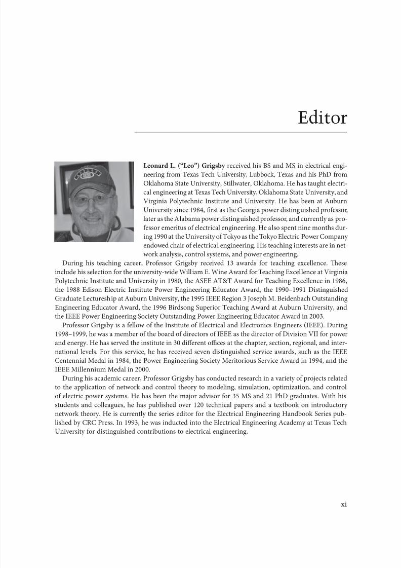
8102019 Power Handbook
httpslidepdfcomreaderfullpower-handbook 1543
xvContributors
Southern Caliornia Edison Company
Rosemead Caliornia
ConsultantPittsburgh Pennsylvania
Department o Electrical and Computer
Engineering
Virginia ech
Arlington Virginia
School o Electrical and Computer
EngineeringOklahoma State University
Stillwater Oklahoma
Electrical Engineering Academic Unit
Universidad Autoacutenoma de Zacatecas
Zacatecas Mexico
Baltimore Gas and Electric Company
Dameron Maryland
Stantec Consulting
Portland Oregon
Electric Power Research InstituteBurnt Hills New York
Department o Electrical Engineering
University o exas at Arlington
Arlington exas
f
Department o Electrical Engineering
University o exas at Arlington
Arlington exas
T
Salt River Project
Phoenix Arizona
y T
Southwire Company
Carrollton Georgia
Hydro-Queacutebec Institute o Research
Boucherville Quebec Canada
8102019 Power Handbook
httpslidepdfcomreaderfullpower-handbook 1643
34-1
Linear electric motors belong to the group o special electrical machines that convert electrical energy
directly into mechanical energy o translatory motion Linear electric motors can drive a linear-motion
load without intermediate gears screws or crank shafs Linear electric motors can be classi1047297ed as ollows
bull DC motorsbull Induction motors
bull Synchronous motors including reluctance and stepping motors
bull Oscil lating motors
bull Hybrid motors
Te application o DC linear motor is marginal Te most popular are permanent magnet (PM) linear
synchronous motors (LSMs) and linear induction motors (LIMs) which are manuactured commer-
cially in several countries and are 1047297nding many applications
A linear motor can be obtained by cutting a rotary motor along its radius rom the center axis o the
shaf to the external surace o the stator core and rolling it out 1047298at (Figure 341)
341 Linear Synchronous Motors3411 Basic Geometries and Constructions
An LSM is a linear motor in which the mechanical motion is in synchronism with the magnetic 1047297eld
ie the mechanical speed is the same as the speed o the traveling magnetic 1047297eld Te thrust (propulsion
orce) can be generated as an action o
bull raveling magnetic 1047297eld produced by a polyphase winding and an array o magnetic poles N
S hellip N S or a variable reluctance erromagnetic rail (LSMs with AC armature windings)
bull Magnetic 1047297eld produced by electronically switched DC windings and an array o magnetic poles N
S hellip N S or variable reluctance erromagnetic rail (linear stepping or switched reluctance motors)
34Linear Electric Motors
341 Linear Synchronous Motors -1Basic Geometries and Constructions bull Classi1047297cation bull Flux-
Switching PM Linear Motors bull Motors with Electromagnetic
Excitation bull Motors with Superconducting Excitation System
342 Linear Induction Motors -14
Basic Geometries and Constructions bullPropulsion o Wheel-on-Rail Vehicles
343 Variable Reluctance Motors -21344 Stepping Motors -22345 Switched Reluctance Motors -25346 Linear Positioning Stages -26Reerences -27
Jacek F GierasUniversity of Technology
and Life Sciences
8102019 Power Handbook
httpslidepdfcomreaderfullpower-handbook 1743
34-2 Electric Power Generation Transmission and Distribution
Te part producing the traveling magnetic 1047297eld is called the armature or orcer Te part that provides
the DC magnetic 1047298ux or variable reluctance is called the 1047297eld excitation system (i the excitation system
exists) or salient-pole rail reaction rail or variable reluctance platen Te terms primary and secondary
should rather be avoided as they are only justi1047297ed or LIMs [6] or transormers Te operation o an
LSM does not depend on which part is movable and which one is stationary
raditionally AC polyphase synchronous motors are motors with DC electromagnetic excitation the
propulsion orce o which has two components (1) due to the traveling magnetic 1047297eld and DC currentmagnetic 1047298ux (synchronous component) and (2) due to the traveling magnetic 1047297eld and variable reluc-
tance in d - and q-axes (reluctance component) Replacement o DC electromagnets with PMs is common
except or LSMs or magnetically levitated vehicles PM brushless LSMs can be divided into two groups
bull PM LSMs in which the input current waveorms are sinusoidal and produce a traveling magnetic
1047297eld
bull PM DC linear brushless motors (LBMs) with position eedback in which the input rectangular
or trapezoidal current waveorms are precisely synchronized with the speed and position o the
moving part
Construction o magnetic and electric circuits o LSMs belonging to both groups is the same LSMs can
be designed as 1047298at motors (Figure 342) or tubular motors (Figure 343) In DC brushless motors theinormation about the position o the moving part is usually provided by an absolute position sensor
Tis control scheme corresponds to an electronic commutation unctionally equivalent to the mechani-
cal commutation in DC commutator motors Tereore motors with square (trapezoidal) current wave-
orms are called DC brushless motors
Instead o DC or PM excitation the difference between the d - and q-axes reluctances and the traveling
magnetic 1047297eld can generate the reluctance component o the thrust Such a motor is called the AC vari-
able reluctance LSM Different reluctances in the d - and q-axes can be created by making salient erro-
magnetic poles using erromagnetic and nonerromagnetic materials or using anisotropic erromagnetic
materials Te operation o LBMs can be regarded as a special case o the operation o LSMs
1
1
2
2
x
x
v
v
z
z
y
(a)
(b)
y
0
0
1
1
2
2 x
xv
z z
v g
y y
0
0
1 2
21
y
v 0 x
z
d
g 1
g 2
x
z
y
v
0
Evolution o a rotary induction motor (a) solid-rotor induction motor into a 1047298at single-sided LIM
and (b) hollow-rotor induction motor into a 1047298at double-sided LIM 1 primary 2 secondary
8102019 Power Handbook
httpslidepdfcomreaderfullpower-handbook 1843
34-3Linear Electric Motors
In the case o LSMs operating on the principle o the traveling magnetic 1047297eld the speed v o the mov-
ing part is equal to synchronous speed v s ie
v v s= = =2 τ ω
πτ
(341)
Te synchronous speed v s o the traveling magnetic 1047297eld depends only on the input requency (angular
input requency ω = 2π ) and pole pitch τ It does not depend on the number o poles 2 p
As or any other linear-motion electrical machine the useul orce (thrust) F x is directly proportional
to the output power P out and inversely proportional to the speed v = v s ie
F
P
v x
out
s
=
(342)
Flat three-phase PM linear motors (Photo courtesy o Kollmorgen Radord VA)
ubular PM LSM Moving rod (reaction rail) contains circular PMs (Photo courtesy o Caliornia
Linear Drives Carlsbad CA)
8102019 Power Handbook
httpslidepdfcomreaderfullpower-handbook 1943
34-4 Electric Power Generation Transmission and Distribution
Direct electromechanical drives with LSMs or actory automation systems can achieve speeds exceeding
600 mmin = 36 kmh and acceleration o up to 360 ms2 [7] Te thrust density ie thrust per active sur-
ace 2 pτLi where Li is the effective width o the stack
F
p Lx
x
i
=2
(Nm2
τ)
(343)
o LSMs is higher than that o LIMs (Figure 344)
Te polyphase (usually three-phase) armature winding can be distributed in slots made in the orm
o concentrated-parameter coils or made as a coreless (air-cored) winding layer PMs are the most popu-
lar 1047297eld excitation systems or short traveling distances (less than 10 m) or example actory transporta-
tion or automation systems A long PM rail would be expensive Electromagnetic excitation is used in
high-speed passenger transportation systems operating on the principle o magnetic levitation (maglev)
Te German system ransrapid uses vehicle-mounted steel core excitation electromagnets and station-
ary slotted armatures Japanese MLX001 test train sets use onboard superconducting (SC) air-cored
electromagnets and a stationary three-phase air-cored armature winding distributed along the guide-
way (Yamanashi Maglev est Line)
3412 Classi1047297cation
LSMs can be classi1047297ed according to whether they are
bull Flat (planar) or tubular (cylindrical)
bull Single sided or double sided
bull Slotted or slotless
0
10000
20000
30000
40000
50000
60000
0 2000 4000 6000 8000 10000 12000 14000
Trust N
T h r u s t d e n s i t y N m 2
LSM OC
LSM WC
LSM AC
LSM NC
LIM NC
Comparison o thrust density or single-sided LIMs and LSMs AC air cooling NC natural cool-
ing OC oil cooling WC water cooling (From Gieras JF Status o linear motors in the United States International
Symposium on Linear Drives or Industry Applications (LDIArsquo03) Birmingham UK pp 169ndash176 2003)
8102019 Power Handbook
httpslidepdfcomreaderfullpower-handbook 2043
34-5Linear Electric Motors
bull Iron cored or air cored
bull ransverse 1047298ux or longitudinal 1047298ux
Te topologies mentioned earlier are possible or nearly all types o excitation systems LSMs operating
on the principle o the traveling magnetic 1047297eld can have the ollowing excitation systems
bull PMs in the reaction railbull PMs in the armature (passive reaction rail)
bull Electromagnetic excitation system (with winding)
bull SC excitation system
bull Passive reaction rail with saliency and neither PMs nor windings (variable reluctance motors)
LSMs with electronically switched DC armature windings are designed either as linear stepping motors
or linear switched reluctance motors
34121 PM Motors with Active Reaction Rail
Figure 345a shows a single-sided 1047298at LSM with the armature winding located in slots and surace PMs
Figure 345b shows a similar motor with buried-type PMs In surace arrangement o PMs the yoke(back iron) o the reaction rail is erromagnetic and PMs are magnetized in the normal direction (per-
pendicular to the active surace) Buried PMs are magnetized in the direction o the traveling magnetic
1047297eld and the yoke is nonerromagnetic or example made o aluminum (Al) Otherwise the bottom
leakage 1047298ux would be greater than the linkage 1047298ux as shown in Figure 346 Te same effect occurs in
buried-type PM rotors o rotary machines in which the shaf must also be nonerromagnetic [239]
Te so-called Halbach array o PMs also does not require any erromagnetic yoke and excites stronger
magnetic 1047298ux density and closer to the sinusoids than a conventional PM array Te key concept o the
Halbach array is that the magnetization vector should rotate as a unction o distance along the array
(Figure 347)
It is recommended that a PM LSM be urnished with a damper A rotary synchronous motor has a cage
damper winding embedded in pole shoe slots When the speed is different rom the synchronous speed
electric currents are induced in damper circuits Te action o the armature magnetic 1047297eld and damper
currents allows or asynchronous starting damps the oscillations and helps to return to synchronous
operation when the speed decreases or increases Also a damper circuit reduces the backward-traveling
magnetic 1047297eld It would be rather difficult to urnish PMs with a cage winding so that the damper o PM
LSMs has the orm o an Al cover (Figure 348a) or solid steel pole shoes (Figure 348b) In addition steel
pole shoes or Al cover (shield) can protect brittle PMs against mechanical damage
Te detent orce ie attractive orce between PMs and the armature erromagnetic teeth orce ripple
and some higher-space harmonics can be reduced with the aid o skewed assembly o PMs Skewed PMs
can be arranged in one row (Figure 349a) two rows (Figure 349b) or even more rows
1 3
(a) (b)
N
S
τ τ
S
N
1 2 3
N S
τ τ
S N
Single-sided 1047298at PM LSMs with slotted armature core and (a) surace PMs and (b) buried PMs
1 PM 2 mild steel pole 3 yoke
8102019 Power Handbook
httpslidepdfcomreaderfullpower-handbook 2143
34-6 Electric Power Generation Transmission and Distribution
(a)
(b)
Magnetic 1047298ux distribution in the longitudinal sections o buried-type PM LSMs (a) nonerromag-
netic yoke and (b) erromagnetic yoke (back iron)
1
2
Double-sided LSM with Halbach array o PMs 1 PMs 2 coreless armature winding
2
2
3(a)
(b)
3
1
1
Dampers o surace-type PM LSMs (a) Al cover (shield) and (b) solid steel pole shoes 1 PM
2 damper 3 yoke
8102019 Power Handbook
httpslidepdfcomreaderfullpower-handbook 2243
34-7Linear Electric Motors
Speci1047297cation data o 1047298at single-sided PM LBMs manuactured by Anorad are shown in able 341 [1]
and motors manuactured by Kollmorgen are shown in able 342 [11] Te temperature 25degC 125degC
or 130degC or the thrust current resistance and power loss is the temperature o the armature winding
Te electromotive orce (EMF) constant kE in ables 341 and 342 or sinusoidal operation is de1047297ned
according to the equation expressing the EMF (induced voltage) excited by PMs without the armature
reaction ie
E k v E s=
(344)
where v s is the synchronous speed according to Equation 341 Tus the armature constant kE multiplied
by the synchronous speed v s gives the EMF E
S SN N N N N N
N N N N N N
N N N N N N
S S S S
S S S S S S
S
(b)
(a)
S S S S S
Skewed PMs in 1047298at LSMs (a) one row and (b) two rows
Flat Tree-Phase Single-Sided PM LBMs with Natural Cooling Systems
Manuactured by Anorad Hauppauge NY
Parameter LCD--1 LCD--2-P LCD--3-P LCD--4-P
Continuous thrust at 25degC N 163 245 327 490
Continuous current at 25degC A 42 63 85 127
Continuous thrust at 125degC N 139 208 277 416
Continuous current at 125degC A 36 54 72 108
Peak thrust (025 s) N 303 455 606 909
Peak current (025 s) A 92 138 184 276
Peak orce (10 s) N 248 373 497 745
Peak current (10 s) A 73 110 147 220Continuous power losses at 125degC W 58 87 115 173
Armature constant kE Vsm 129
Trust constant (three phases) kF NA 386
Resistance per phase at 25degC Ω 32 22 16 11
Inductance mH 143 95 71 48
PM pole pitch mm 2345
Maximum winding temperature degC 125
Armature assembly mass kg 18 24 36 48
PM assembly mass kgm 64
Normal attractive orce N 1036 1555 2073 3109
8102019 Power Handbook
httpslidepdfcomreaderfullpower-handbook 2343
34-8 Electric Power Generation Transmission and Distribution
Te thrust constant kF in ables 341 and 342 is de1047297ned according to the simpli1047297ed equation or the
developed electromagnetic thrust ie
F k I dx F a= cos Ψ
(345)
or a sinusoidally excited LSM with equal reluctances in the d - and q-axes and or the angle between the
armature current I a and the q-axis Ψ = 0deg (cos Ψ = 1) Tus the thrust constant kF times the armature
current I a gives the electromagnetic thrust developed by the LSM
Double-sided 1047298at PM LSMs consist o two external armature systems and one internal excitation sys-
tem (Figure 3410a) or one internal armature system and two external excitation systems (Figure 3410b)
In the second case a linear Grammersquos armature winding can be used
In slotless motors the primary winding is uniormly distributed on a smooth armature core or does
not have any armature core Slotless PM LSMs are detent orcendashree motors provide lower torque ripple
and at high input requency can achieve higher efficiency than slotted LSMs On the other hand larger
nonerromagnetic air gap requires more PM material and the thrust density (thrust per mass or volume)
is lower than that o slotted motors (able 343) Te input current is higher as synchronous reactances
Flat Tree-Phase Single-Sided PM LBMs with Natural Cooling Systems
Manuactured by Kollmorgen Radord VA
Parameter IC11-030 IC11-050 IC11-100 IC11-200
Continuous thrust at 130degC N 150 275 600 1260
Continuous current at 130degC A 40 44 48 50
Peak thrust N 300 500 1000 2000
Peak current A 79 79 79 79
Continuous power losses at 130degC W 64 106 210 418
Armature constant at 25degC kE Vsm 309 514 1028 2057
Trust constant (three phases) at 25degC kF NA 378 629 1259 2519
Resistance line to line at 25degC Ω 19 26 44 80
Inductance line to line mH 173 278 541 1066
Electrical time constant ms 89 105 123 134
Termal resistance winding to external
structure degCW
164 099 050 025
Maximum winding temperature degC 130
Armature assembly mass kg 20 32 62 122PM assembly mass kgm 55 76 128 269
Normal attractive orce N 1440 2430 4900 9850
(a)
N S N SN S N S
N S N SN S N S
(b)
Double-sided 1047298at PM LSMs with (a) two external armature systems and (b) one internal armature
system
8102019 Power Handbook
httpslidepdfcomreaderfullpower-handbook 2443
34-9Linear Electric Motors
in the d - and q-axes can decrease to a low undesired value due to the absence o teeth Figure 3411a
shows a single-sided 1047298at slotless motor with armature core and Figure 3411b shows a double-sided slot-
less motor with inner air-cored armature winding (moving coil motor)
able 344 contains perormance speci1047297cations o double-sided PM LBMs with inner three-phase air-
cored armature winding manuactured by rilogy Systems Corporation Webster X (Figure 3412)
N
(a) (b)
S N S N S N S
S N NS
Flat slotless PM LSMs (a) single-sided with armature core and (b) double-sided with inner air-
cored armature winding
Slotted versus Slotless LSMs
Quantity Slotted LSM Slotless LSM
Higher thrust density X
Higher efficiency in the lower speed range X
Higher efficiency in the higher speed range x
Lower input current X
Less PM material X
Lower winding cost x
Lower thrust pulsations x
Lower acoustic noise x
Flat Double-Sided PM LBMs with Inner Tree-Phase Air-Cored Series-Coil
Armature Winding Manuactured by rilogy Systems Corporation Webster X
Parameter 310-2 310-4 310-6
Continuous thrust N 1112 2091 3149
Continuous power or sinusoidal operation W 87 152 230
Peak thrust N 356 712 1068
Peak power W 900 1800 2700
Peakcontinuous current A 10028 10026 10026
Trust constant kF or sinusoidal operation NA 400 800 1200
Trust constant kF or trapezoidal operation with Hallsensors NA
351 725 1095
Resistance per phase Ω 86 172 258
Inductance plusmn05 mH 60 120 180
Heat dissipation constant or natural cooling WdegC 110 201 301
Heat dissipation constant or orced air cooling WdegC 130 240 355
Heat dissipation constant or liquid cooling WdegC 154 285 421
Number o poles 2 4 6
Coil length mm 1422 2642 3861
Coil mass kg 055 103 153
Mass o PM excitation systems kgm 1267 or 838
8102019 Power Handbook
httpslidepdfcomreaderfullpower-handbook 2543
34-10 Electric Power Generation Transmission and Distribution
By rolling a lat LSM around the axis parallel to the direction o the traveling magnetic ield
ie parallel to the direction o thrust a tubular (cylindrical) LSM can be obtained (Figure 3413) A
tubular PM LSM can also be designed as a double-sided motor or slotless motor
ubular single-sided LSMs LinMoreg with movable internal PM excitation system (slider) and stationaryexternal armature are manuactured by Sulzer Electronics AG Zurich Switzerland (able 345) All active
motor parts bearings position sensors and electronics have been integrated into a rigid metal cylinder [14]
LinMotreg is a registered trademark o Sulzer Electronics AG Zuumlrich Switzerland
(b)(a)
N S N S N S
N S N S N S
N S N S
SNN S
Single-sided slotted tubular PM LSMs (a) with external armature system and (b) with external
excitation system
Data o ubular LSMs LinMotreg Manuactured by Sulzer Electronics AG Zuumlrich Switzerland
Parameter P01 23 times 80 P01 23 times 160 P01 37 times 120 P01 37 times 240
Number o phases 2
PMs NdFeB
Maximum stroke m 0210 0340 1400 1460Maximum orce N 33 60 122 204
Maximum acceleration ms2 280 350 247 268
Maximum speed ms 24 42 40 31
Stator (armature) length m 0177 0257 0227 0347
Stator outer diameter mm 23 23 37 37
Stator mass kg 0265 0450 0740 1385
Slider diameter mm 12 12 20 20
Maximum temperature o the armature winding degC 90
Flat double-sided PM LSM with inner moving coil (Photo courtesy o rilogy Systems Webster X)
8102019 Power Handbook
httpslidepdfcomreaderfullpower-handbook 2643
34-11Linear Electric Motors
All the aorementioned PM LSMs are motors with longitudinal magnetic 1047298ux the lines o which lie
in the plane parallel to the direction o the traveling magnetic 1047297eld LSMs can also be designed as trans-
verse magnetic 1047298ux motors in which the lines o magnetic 1047298ux are perpendicular to the direction o the
traveling 1047297eld Figure 3414a shows a single-sided transverse 1047298ux LSM in which PMs are arranged in two
rows A pair o parallel PMs creates a two pole 1047298ux excitation system A double-sided con1047297guration o
transverse 1047298ux motor is possible however it is complicated and expensive (Figure 3414b)
34122 PM Motors with Passive Reaction Rail
Te drawback o PM LSMs is the large amount o PM material that must be used to design the excitation
system Normally expensive rare-earth PMs are requested I a small PM LSM uses say 10 kg o NdFeB
per 1 m o the reaction rail and 1 kg o good-quality NdFeB costs US$ 130 the cost o the reaction rail
without assembly amounts to US$ 1300 per 1 m Tis price cannot be acceptable or example in pas-
senger transportation systems
A cheaper solution is to apply the PM excitation system to the short armature that magnetizes the
long reaction rail and creates magnetic poles in it Such a linear motor is called the homopolar LSM
Te homopolar LSM as described in [517] is a double-sided AC linear motor that consists o two
polyphase armature systems connected mechanically and magnetically by a erromagnetic U-type yoke
(Figure 3415) Each armature consists o a typical slotted linear motor stack with polyphase armature
winding and PMs located between the stack and U-type yoke Since the armature and excitation systems
are combined together the armature stack is oversized as compared with a conventional steel-cored LSM
Te PMs can also be replaced by electromagnets [1719] Te variable reluctance reaction rail is passive
Te saliency is created by using erromagnetic (solid or laminated) cubes separated by a nonerromag-netic material Te reaction rail poles are magnetized by the armature PMs through the air gap Te trav-
eling magnetic 1047297eld o the polyphase armature winding and salient poles o the reaction rail produce the
thrust Such a homopolar LSM has been proposed or the propulsion o maglev trains o Swissmetro [17]
Further simpli1047297cation o the double-sided con1047297guration can be made to obtain a single-sided PM
LSM shown in Figure 3416
3413 Flux-Switching PM Linear Motors
Large gantry systems and machining centers require powerul linear motors preerably with PM-ree
reaction rail Siemens 1FN6 PM LSMs with a magnet-ree reaction rail belong to the group o the so
5
(a) (b)
5
N S
N
N
3
4
4
3
2
6
1
3
6
1
6
1
i
S
2
2
N
N
SNN
S
ransverse 1047298ux PM LSM (a) single-sided and (b) double-sided 1 armature winding 2 armature
laminated core 3 PM 4 back erromagnetic core 5 magnetic 1047298ux 6 armature current
8102019 Power Handbook
httpslidepdfcomreaderfullpower-handbook 2743
34-12 Electric Power Generation Transmission and Distribution
called 1047298ux-switching PM machines [1016] Te armature system is air cooled degree o protection IP23
class o insulation F line voltage rom 400 to 480 V rated thrust rom 235 to 2110 N maximum veloc-
ity at rated thrust rom 170 to 540 mmin (able 346) overload capacity 38 o rated thrust modular
type construction [20] Tese LSMs operate with Siemens Sinamics or Simodrive solid-state converters
and external encoders According to Siemens [20] these new LSMs produce thrust orces and velocities
equivalent to competitive classical models or light-duty machine tool machine accessory and material
handling applications
2 3 244 1
N
S
S
N
N
S
S
N
5
Single-sided PM LSM with a passive reaction rail 1 PM 2 armature winding 3 armature stack
4 yoke 5 erromagnetic reaction rail
1
1
2 343
5
Fe Fe Fe Fe
Double-sided homopolar PM LSM with passive reaction rail 1 PM 2 armature winding
3 armature stack 4 yoke 5 reaction rail
Speci1047297cations o 1FN6 PM LSMs Manuactured by Siemens Erlangen Germany
Armature Unit Rated Trust N Max Trust N
Max Speed at
Rated Trust
mmin
Max Speed at
Max Trust
mmin
Rated
Current A Max Current A
1FN6008-1LC17 235ndash350 900 263 103 17ndash26 90
1FN6008-1LC37 235ndash350 900 541 224 35ndash53 180
1FN6016-1LC30 470ndash710 1800 419 176 54ndash80 280
1FN6016-1LC17 935ndash1400 3590 263 101 70ndash105 360
1FN6024-1LC12 705ndash1060 2690 176 69 35ndash53 180
1FN6024-1LC20 705ndash1060 2690 277 114 54ndash80 280
1FN6024-1LG10 2110ndash3170 8080 172 62 105ndash160 540
1FN6024-1LG17 2110ndash3170 8080 270 102 162ndash243 840
Source Synchronous Linear Motor 1FN6 Te Electrical Gear Rack Siemens AG Industry Sector Drive echnologies
Motion Control Erlangen Germany 2008
8102019 Power Handbook
httpslidepdfcomreaderfullpower-handbook 2843
34-13Linear Electric Motors
Te magnet-ree reaction rail is easy to install and does not require the saety considerations o stan-
dard PM reaction rails Without PMs there is no problem with errous chips and other debris beingattracted to these sections Maintenance becomes a simple matter o installing a wiper or brush on the
moving part o the slide
Te 1047298ux-switching LSM comprises an armature section that is equipped with coils and PMs as well
as a nonmagnetic toothed reaction rail section (Figure 3417) Te key design innovation is an LSM in
which PMs are integrated directly into the lamination o the armature core along with the individual
windings or each phase Both magnitudes and polarities o the linkage 1047298ux in the armature winding
vary periodically along with the reaction rail movement Te magnetic 1047298ux between the armature core
and steel reaction rail is controlled by switching the three-phase armature currents according to a desig-
nated algorithm Te passive reaction rail consists o milled steel with poles (teeth) and is much simpler
to manuacture
3414 Motors with Electromagnetic Excitation
Te electromagnetic excitation system o an LSM is similar to the salient-pole rotor o a rotary
synchronous motor Figure 3418 shows a 1047298at single-sided LSM with salient erromagnetic poles and
DC 1047297eld excitation winding Te poles and pole shoes can be made o solid steel laminated steel or sin-
tered powder I the electromagnetic excitation system is integrated with the moving part the DC cur-
rent can be delivered with the aid o brushes and contact bars inductive power transer (IP) systems
linear transormers or linear brushless exciters
A AB BC C
1
2
3
4
5
v
τ2
τ1
Construction o 1047298ux-switching LSM with PM-ree reaction rail 1 laminated armature core
2 PM 3 armature coil (phase C) 4 toothed passive steel reaction rail 5 linkage magnetic 1047298ux (phase A is on)
1
3
τ τ
2
S
d d q q q
4
N
Electromagnetic excitation system o a 1047298at single-sided iron-cored LSM 1 salient pole 2 DC
excitation winding 3 erromagnetic rail (yoke) 4 armature system
8102019 Power Handbook
httpslidepdfcomreaderfullpower-handbook 2943
34-14 Electric Power Generation Transmission and Distribution
LSMs with electromagnetic excitation (wound-1047297eld reaction rail) are used in German ransrapid
maglev train (Figure 3419)
3415 Motors with Superconducting Excitation System
In large-power LSMs the electromagnets with erromagnetic core that produce the excitation 1047298ux can
be replaced by coreless SC electromagnets Since the magnetic 1047298ux density produced by the SC electro-
magnet is greater than the saturation magnetic 1047298ux density o the best laminated alloys ( Bsat asymp 24 or
cobalt alloy) there is no need to use the armature erromagnetic core An LSM with SC 1047297eld excitation
system is a totally air-cored machine (Figure 3420)
Experimental maglev trains on the Yamanashi Maglev est Line (YML) in Yamanashi Preecture(west rom okyo) Japan are driven by air-cored LSMs with SC excitation systems ( Figure 3421)
342 Linear Induction Motors
LIMs have ound the widest prospects or applications in transportation systems beginning with electri-
cal traction on small passenger or material supply cars (used at airports exhibitions electrohighways
elevators) and ending with pallet transportation waer transportation belt conveyors transportation
systems o bulk materials etc Te second important place or LIM applications is in industry ie man-
uacturing processes (machine tools hammers presses mills separators automated manuacturing systems
strip tensioners textile shuttles index tables turntables disk saws or wood sliding doors robots etc)
ransrapid 09 maglev train driven by LSMs with electromagnetic excitation (Photo courtesy oTyssen ransrapid System GmbH Munich Germany)
1
2A
B
C B
A
A
C
S SN
τ τ τ τ τ
N N
CBA
Tree-phase air-cored LSM with SC excitation system 1 armature coils 2 SC excitation coils
8102019 Power Handbook
httpslidepdfcomreaderfullpower-handbook 3043
34-15Linear Electric Motors
LIMs can also play an important part in industrial investigations and tests or example high acceleration
o model aircraf in aerodynamic tunnels high acceleration o vessels in laboratory pools propulsion o
mixers shakers and vibrators and adjusting xndashy tables and instruments Tere is also a possibility o
using LIMs in consumer electronics (sound and vision equipment knitting machines curtains) and in
offices (transportation o documents letters and cash) Te Handbook o Linear Motor Applications [21]
printed in Japan in 1986 contains about 50 examples o applications o LIMs in operation or in the pro-
cess o implementation
3421 Basic Geometries and Constructions
A LIM can be obtained by cutting in the same way either a cage rotor induction motor or a wound rotor
induction motor Te stator becomes the primary and the rotor becomes the secondary [12] Te secondary
o a LIM can be simpli1047297ed by using a solid steel core and replacing the cage (ladder) or slip-ring winding with
a high-conductivity nonerromagnetic plate (Al or Cu) Te nonerromagnetic plate is a secondary electric
circuit with distributed parameters and the erromagnetic core is a conductor both or the magnetic 1047298ux
and the electric current It does not matter rom the principle o operation point o view which part (primary
or secondary) is in motion Tus the 1047298at single-sided LIM can be obtained rom a solid rotor induction
motor (Figure 341a) and the 1047298at double-sided LIM can be obtained rom a hollow-rotor induction motor
with wound external and internal stator (Figure 341b) In a double-sided LIM the secondary erromagneticcore is not necessary since the magnetic 1047298ux excited by one o the primary windings afer passing through
the air gaps and nonerromagnetic secondary is then closed up by the core o the second primary unit
Teoretically a double-sided LIM with primary windings located on two cores in comparison with a
single-sided LIM exciting the same MMF has twice the air gap magnetic 1047298ux density Tereore the thrust
o such a motor is our times greater assuming the same dimensions I only one primary core is wound
the output parameters o a double-sided LIM are the same as those or a single-sided LIM with laminated
secondary back iron Te undamental advantage o double-sided LIMs is the elimination o the normal
attractive orce between the primary and the secondary because the secondary is usually nonerromagnetic
Flat LIMs can have primary cores consisting o an array o cores arranged in parallel at appropri-
ate distances and connected magnetically by additional yokes perpendicular to the direction o the
YML in Yamanashi Preecture (near okyo) Japan YML maglev trains use air-cored LSMs
with SC excitation system (Photo courtesy o Central Japan Railway Company and Railway echnical Research
Institute okyo Japan)
8102019 Power Handbook
httpslidepdfcomreaderfullpower-handbook 3143
34-16 Electric Power Generation Transmission and Distribution
traveling 1047297eld A magnetic circuit designed in such a way makes it possible to apply two windings in
general multiphase windings with perpendicular conductors as shown in Figure 3422 Adjusting the
current in each winding the secondary can be moved in two perpendicular directions and can be posi-
tioned at any point o the xndashy plane A 1047298at LIM with two degrees o reedom (DOFs) can be designed both
as single-sided and double-sided machines
By rolling a 1047298at single-sided or double-sided LIM around the axis parallel to the direction o the travel-
ing magnetic 1047297eld ie parallel to the direction o the thrust a tubular motor can be obtained (Figure 3423)
A tubular (cylindrical) LIM similar to a 1047298at LIM can be designed both as single-sided and double-
sided machines and can have a square or rectangular cross section as in Figure 3424 Tere are possible
Te primary o a 1047298at LIM with two DOFs
g
g
g 1
g 2
(c)
(b)
(a)
d
v
v
v
1
1
1 1
1
1
2
2
2
2
2
2
ubular LIMs (a) single-sided with an external short primary (b) single-sided with an external
short secondary and (c) double-sided with short primary 1 primary 2 secondary
8102019 Power Handbook
httpslidepdfcomreaderfullpower-handbook 3243
34-17Linear Electric Motors
con1047297gurations other than that in Figure 3423 regarding the length o the secondary with respect to thelength o the primary
All the aorementioned LIMs are motors with longitudinal magnetic 1047298ux ie the lines o magnetic
1047298ux lie in the plane parallel to the direction o the traveling magnetic 1047297eld A LIM can also be designed
in such a way as to obtain magnetic 1047298ux lines perpendicular to the direction o the traveling 1047297eld Such
motors are said to have transverse magnetic 1047298ux (Figure 3425)
Te undamental advantage o a LIM with transverse magnetic 1047298ux in comparison with a LIM with
longitudinal magnetic 1047298ux is the lower magnetizing current necessary due to the shorter magnetic 1047298ux
paths Te signi1047297cant disadvantage is lower thrust A 1047298at LIM with transverse magnetic 1047298ux usually has
a primary winding o concentrated coils located on salient poles
A 1047298at single-sided LIM with transverse 1047298ux can produce not only thrust but also electrodynamic
suspension In the design shown in Figure 3426 the secondary is suspended electrodynamically andpropelled and stabilized laterally by the primary magnetic 1047297eld [8] Te primary magnetic circuit con-
sists o E-shaped laminations assembled in two rows Te short secondary is made o light Al alloy in the
orm o a boat Te lateral sides o the boat are inclined by 60deg with respect to the active surace Such a
shape provides maximum normal repulsive orce and maximum lateral stabilization
According to their geometry the LIMs can be divided into the ollowing groups
bull With movable primary or movable secondary
bull Single sided and double sided
bull Flat and tubular
bull With short primary and short secondary
bull With longitudinal and transverse magnetic 1047298ux
1 2 3 4 1 2 3 4
ubular double-sided LIM with a square cross section 1 primary 2 secondary 3 primary coil
4 internal core
v
v
1 1
1
1
(a)
(b)
22
22
Flat LIM with transverse magnetic 1047298ux and salient poles (a) single-sided and (b) double-sided
1 primary 2 secondary
8102019 Power Handbook
httpslidepdfcomreaderfullpower-handbook 3343
34-18 Electric Power Generation Transmission and Distribution
Te linear speed o a LIM is
v s v s= minus( )1 (346)
where
s is the slip
v s is the synchronous speed according to Equation 341
Neglecting the longitudinal end effect [6] the electromagnetic thrust developed by a LIM can be
expressed in a similar way as or a rotary induction motor ie
F
m
v I
R
sdx
s
= prime( ) prime1
2
2 2
(347)
where
m1 is the number o phases o the primary winding
v s is the synchronous speed according to Equation 341
primeI 2 is the secondary current reerred to the primary system
primeR2 is the secondary resistance reerred to the primary system
s is the slip
Te secondary resistance primeR2 must include the so-called edge effect [6]
3422 Propulsion of Wheel-on-Rail Vehicles
Modern railway systems and electrical traction should meet the ollowing requirements
bull High level o automatization and computerization
bull Propulsion and braking independent o adhesion which in turn is affected 1047297rst o all by climate
and weather
bull Low level o noise sometimes below 70 dB (A)
Flat LIM with transverse magnetic 1047298ux salient poles and nonerromagnetic secondary pro-
pelled suspended and stabilized electrodynamically (From Gieras JF et al Analytical calculation o electro-
dynamic levitation orces in a special-purpose linear induction motor International Electric Machines and Drives
Conerence (IEMDCrsquo11) Niagara Falls Ontario Canada 2011 [on CD-ROM])
8102019 Power Handbook
httpslidepdfcomreaderfullpower-handbook 3443
34-19Linear Electric Motors
bull Ability to cope with high slopes at least 6 and sharp bends with radius o curvature less than 20 m
bull No pollution to natural environment and landscape
bull High reliability
Te congestion problems o big cities should be solved by creating collective transport orms that can be
implemented without affecting a highly populated city For example there are many cities in Italy where
the historical center has remained the same since the Renaissance A heavy railway might be a com-
pletely wrong solution and have a notable impact on the city planning An adequate solution might be
a light railway a people mover with transport capacity o 10000ndash20000 passengers per hour to replace
the traditional transport nets and to integrate the existing railway nets
All the requirements mentioned earlier can be met by using LIMs as propulsion machines Replacing
electrical rotary motors with linear motors in traction drives (electrical locomotives) generally does
not require new tracks but only their adjustment to linear drives Single-sided LIMs (Figure 3427a and b)
are best since the normal attractive orce o these can strengthen the adhesion o wheels and rails
Te air gap is rom 10 to 15 mm Most requently the motor car has two LIMs with short primaries
(Figure 3427a) assembled in series Te double-layer secondary consists o a solid back iron and an Al
cap and is located between the rails Cables or computer communication with the vehicle and quite
ofen collectors or electrical energy delivery to the vehicle are located along the track Tree-phaseLIMs are ed rom variable-voltage variable-requency (VVVF) voltage-source inverters A linear pro-
pulsion system o wheel-on-rail vehicles allows more 1047298exibility (Figure 3428) reducing noise on bends
and wear o the wheels and rails
Double-sided LIMs (Figure 3427c and d) have ound very limited application due to the technical
difficulty o eliminating aults caused by bends in the secondary with primary cores on either side It is
more difficult to keep a small and uniorm air gap in double-sided LIMs than that in single-sided LIMs
Te LIM-driven wheel-on-rail vehicles are built or low velocities ie less than 100 kmh and or
short routes ie less than 50 km (urban transit systems and short-distance trains) At present LIM-
driven trains operate in oronto and Vancouver BC Canada in Detroit MI (Figure 3429) okyo
(Figure 3430) and Osaka Japan and Kuala Lumpur Malaysia
(a) (b)
(c) (d)
LIM-driven wheel-on-rail cars (a) single-sided LIM with short primary mounted on the undercar-
riage (b) single-sided LIM with short secondary mounted on the undercarriage (c) double-sided LIM with short pri-
mary mounted on the undercarriage and (d) double-sided LIM with short secondary mounted on the undercarriage
8102019 Power Handbook
httpslidepdfcomreaderfullpower-handbook 3543
34-20 Electric Power Generation Transmission and Distribution
(a) (b)
Te undercarriage o a wheel-on-rail vehicle (a) rotary motor propulsion and (b) LIM propulsion
Detroit people mover driven by single-sided LIMs
oei Oedo subway line in okyo driven by single-sided LIMs
8102019 Power Handbook
httpslidepdfcomreaderfullpower-handbook 3643
34-21Linear Electric Motors
Te design data o some single-sided traction LIMs are presented in able 347 and double-sided trac-
tion LIMs in able 348
343 Variable Reluctance Motors
Te simplest construction o a variable reluctance LSM or linear reluctance motor (LRM) is that shown
in Figure 3418 with DC excitation winding being removed However the thrust o such a motor wouldbe low as the ratio o d -axis permeance to q-axis permeance is low Better perormance can be obtained
when using 1047298ux barriers [18] or steel laminations [15] o make 1047298ux barriers any nonerromagnetic
materials can be used o obtain high permeance (low reluctance) in the d -axis and low permeance in
the q-axis steel laminations should be oriented in such a way as to create high permeance or the d -axis
magnetic 1047298ux
Figure 3431a shows a variable reluctance platen with 1047298ux barriers and Figure 3431b shows how to
arrange steel laminations to obtain different reluctances in the d - and q-axes Te platen can be com-
posed o segments the length o which is equal to the pole pitchτ Each segment consists o semicircular
lamellas cut out rom electrotechnical sheet A 1047297lling or example epoxy resin is used to make the seg-
ment rigid and robust By putting the segments together a platen o any desired length can be obtained
Design Data o Single-Sided Tree-Phase LIMs or Propulsion o Vehicles
Quantity
LIM
UnitJLMDR ICS KU CIGG GEC
Pullout thrust at requency given
in the ollowing F x
125 90 35 17 07 kN
Input requency 200 400 250 400 600 Hz
Rated phase current V 1 2750 4650 1300 2000 2000 A
Number o poles 2 p 8 6 4 6 4 mdash
Number o turns per phase N 1 128 96 128 108 48 mdash
Equivalent diameter o conductor d 1 mdash 893 528 1115 81 mm
Number o parallel conductors mdash 1 mdash 19 1 mdash
Effective width o primary core Li 023 0216 029 0101 01715 m
Pole pitch τ 027 02868 030 025 020 m
Length o single end connection l e mdash 03483 mdash 02955 03685 m
Coil pitch wc 0225 01673 025 01944 01555 m
Air gap g 150 126 120 150 182 mm
Number o slots z 1( primez 1) 96(106) 72(79) 48(58) 54(61) 36(43) mdash
Width o slot b11 mdash 156 170 150 1308 mm
Width o slot opening b14 mdash 156 mdash 1044 1308 mm
Depth o slot h11 mdash 530 380 3421 6147 mm
Height o yoke h1 y mdash 436 393 7163 500 mm
Conductivity o back iron at 20degC σFe mdash 446 952 446 512 times106 Sm
Conductivity o Al cap at 20degC σ Al mdash 300 303 323 215 times106 Sm
Width o back iron w 03 024 03 0111 01715 m
Tickness o back iron hsec 190 125 250 254 474 mm
Tickness o Al cap d 50 45 50 45(25) 32 mm
Tickness o Al cap behind Fe core t ov 50 170 50 127 32 mm
Width o Al cap 030 032 040 0201 02985 m
JLMDR Japanese Linear Motor Driven Railcar Japan ICS Intermediate Capacity ransit System Canada KU
Kyushu University LIM Japan CIGG Canadian Inst o Guided Ground ransport Canada GEC General
Electric Company United States (z 1 ) is the number o hal 1047297lled slots
8102019 Power Handbook
httpslidepdfcomreaderfullpower-handbook 3743
34-22 Electric Power Generation Transmission and Distribution
344 Stepping Motors
A linear stepping motor has a concentrated armature winding wound on salient poles and PM excitation
rail or variable reluctance platen Te thrust is generated as an action o the armature magnetic 1047298ux and
PM 1047298ux (active platen) or the armature magnetic 1047298ux and salient erromagnetic poles (variable reluc-
tance platen) Stepping motors have no position eedback
Design Data o Double-Sided Tree-Phase LIMs or Propulsion
o Vehicles
Quantity
LIM
UnitGEC LIMVR
Maximum thrust at input requency F x given in the ollowing 085 1668 kN
Input requency 600 1730 Hz
Input phase current I 1 2000 20000 A
Number o poles 2 p 4 10 mdash
Number o turns per phase N 1 144 100 mdash
Diameter o conductor d 1 075 110 mm
Effective width o primary core Li 00869 0254 m
Pole pitch τ 01795 03556 m
Coil pitch wc 005 005 m
Number o slots z 1( primez 1) 36(45) 150(160) mdash
Width o slot b11 137 160 mm
Width o slot opening b14 137 mdash mm
Depth o slot h1 630 mdash mm
Height o yoke h1 y 239 mdash mm
Width o tooth c1 200 77 mm
Resultant air gap 2 g + d 381 38075 mm
Air gap g 2 times 127 2 times 111 mm
Tickness o secondary d 127 15875(hollow) mm
Effective thickness o Al secondary 127 72 mm
Width o secondary w ge03046 mdash m
Conductivity o Al cap at 20degC σ Al asymp2434 asymp240 times106 Sm
GEC General Electric Company United States LIMVR LIM Research Vehicle
Pueblo CO United States (z 1 ) is the number o hal 1047297lled slots
(a) (b)
q q d d d q d q d d
Laminations
τ τ τ τ
Epoxy resin
Variable reluctance LSMs with (a) 1047298ux barriers and (b) steel laminations
8102019 Power Handbook
httpslidepdfcomreaderfullpower-handbook 3843
8102019 Power Handbook
httpslidepdfcomreaderfullpower-handbook 3943
34-24 Electric Power Generation Transmission and Distribution
Tis value is different or ull-step and microstepping drives Te maximum startndashstop speed is the
maximum speed that can be used when starting or stopping the motor without ramping that does not
cause the motor to all out o synchronism or lose steps Te maximum speed is the maximum linear
speed that can be achieved without the motor stalling or alling out o synchronism Te maximum
load mass is the maximum allowable mass applied to the orcer against the scale that does not result in
mechanical damage Te ull-step resolution is the position increment obtained when the currents are
switched rom one winding to the next winding Tis is the typical resolution obtained with ul l-step
drives and it is strictly a unction o the motor construction Te microstepping resolution is the position
increment obtained when the ull-step resolution is divided electronically by proportioning the currents
in the two windings Tis resolution is typically 10ndash250 times smaller than the ull-step resolution [13]
HLSMs are regarded as an excellent solution to positioning systems that require a high accuracy
and rapid acceleration With a microprocessor controlled microstepping mode a smooth operation with
standard resolution o a ew hundred stepsmm can be obtained Te advantages such as high efficiencyhigh throughput mechanical simplicity high reliability precise open-loop operation and low inertia
o the system have made these kind o motors more and more attractive in such applications as actory
automation high speed positioning computer peripherals acsimile machines numerically controlled
machine tools automated medical equipment automated laboratory equipment and welding robots
Tis motor is especially suitable or machine tools printers plotters and computer-controlled material
handling in which a high positioning accuracy and repeatability are the key problems
When two or our orcers mounted at 90deg and a special grooved platen (ldquowaffle platerdquo) are used the
xndashy motion (two DOFs) in a single plane is obtained (Figure 3434)
Speci1047297cation data o the xndashy HLSMs manuactured by Normag Northern Magnetics Inc Santa
Clarita CA are given in able 3410
PM linear stepping motors (Photo courtesy o okyo Aircraf Instrument Co Ltd okyo Japan)
8102019 Power Handbook
httpslidepdfcomreaderfullpower-handbook 4043
34-25Linear Electric Motors
345 Switched Reluctance Motors
Te topology o a linear switched reluctance motor is similar to that o a stepping motor with variable
reluctance platen In addition it is equipped with position sensors Te turn-on and turn-off instant o
the input current is synchronized with the position o the moving part Te thrust is very sensitive to
the turn-on and turn-off instant
In the case o a linear stepping or linear switched reluctance motor the speed v o the moving part is
v v s sw= = τ
(348)
where
sw is the undamental switching requency in one armature phase winding
τ is the pole pitch o the reaction rail
For a rotary stepping or switched reluctance motor sw = 2 pr n where 2 pr is the number o rotor poles and
n is rotational speed in revs
A linear switched reluctance motor has a doubly salient magnetic circuit with a polyphase winding
on the armature Longitudinal and transverse 1047298ux designs are shown in Figure 3435 A linear switched
reluctance motor allows precise speed and position-controlled linear motion at low speeds and is not sub-
ject to design constraints (minimum speed limited by minimum easible pole pitch) o linear AC motors
x
y
12
3
4
1
1
2
2
HLSM with a our-unit orcer to obtain the xndashy motion 1 orcers or the x -direction 2 orcers
or the y -direction 3 platen 4 air pressure
Data o xndashy HLSMs Manuactured by Normag Northern Magnetics Inc
Santa Clarita CA
Parameter 4XY0602-2-0 4XY2002-2-0 4XY2004-2-0 4XY2504-2-0
Number o orcer units per axis 1 1 2 2
Number o phases 2 2 2(4) 2(4)Static thrust N 133 400 980 1330
Trust at 1 ms N 111 311 712 980
Normal attractive orce N 1600 4000 14400 18000
Resistance per phase Ω 29 33 16 19
Inductance per phase mH 15 40 20 23
Input phase current A 20 20 40 40
Air gap mm 002
Maximum temperature degC 110
Mass kg 32 072 20 15
Repeatability mm 000254
Resolution mm 000254
Bearing type Air
8102019 Power Handbook
httpslidepdfcomreaderfullpower-handbook 4143
34-26 Electric Power Generation Transmission and Distribution
346 Linear Positioning Stages
Linear motors are now playing a key role in advanced precision linear positioning Linear precision posi-
tioning systems can be classi1047297ed into open-loop systems with HLSMs and closed-loop servo systems
with LSMs LBMs or LIMs
A PM LSMndashdriven positioning stage is shown in Figure 3436 A stationary base is made o Al steel
ceramic or granite plate It provides a stable precise and 1047298at platorm to which all stationary position-
ing components are attached Te base o the stage is attached to the host system with the aid o mount-
ing screws
Te moving table accommodates all moving positioning components o achieve maximum accelera-
tion the mass o the moving table should be as small as possible and usually Al is used as a lightweight
material A number o mounting holes on the moving table is necessary to 1047297x the payload to the mount-
ing table
Linear bearing rails provide a precise guidance to the moving table A minimum o one bearing rail
is required Linear ball bearing or air bearings are attached to each rail
Te armature o a linear motor is astened to the moving table and reaction rail (PM excitation sys-tem) is built in the base between the rails (Figure 3436)
A linear encoder is needed to obtain precise control o position o the table velocity and acceleration
Te read head o the encoder is attached to the moving table
(a) (b)
3
3
221
1
Linear switched reluctance motor con1047297gurations (a) longitudinal 1047298ux design and (b) transverse
1047298ux design 1 armature winding 2 armature stack 3 platen
12
3
5
4
7
6
8
Linear positioning stage driven by PM LBM 1 base 2 moving table 3 armature o LBM 4 PMs
5 linear bearing 6 encoder 7 cable carrier 8 limit switch (Courtesy o Normag Santa Clarita CA)
8102019 Power Handbook
httpslidepdfcomreaderfullpower-handbook 4243
34-27Linear Electric Motors
Noncontact limit switches ixed to the base provide an overtravel protection and init ial homing
A cable carrier accommodates and routes electrical cables between the moving table and stationary
connector box 1047297xed to the base
An HLSM-driven linear precision stage is o similar construction Instead o PMs between bearing
rails it has a variable reluctance platen HLSMs usually need air bearings and in addition to the electri-
cal cables an air hose between air bearings and the compressor is requiredLinear positioning stages are used in semiconductor technology electronic assembly quality assur-
ance laser cutting optical scanning water jet cutting gantry systems (x y z stages) color printers
plotters and Cartesian coordinate robotics
References
1 Anorad Linear Motors Inormation Brochure Anorad Hauppauge New York 2007 wwwanoradcom
2 Boldea I and Nasar SA Linear Motion Electromagnetic Systems John Wiley amp Sons New York 1985
3 Boldea I and Nasar SA Linear Electric Actuators and Generators Cambridge University Press
New York 2005
4 Compumotor Digiplan Positioning Control Systems and Drives Parker Hanni1047297n CorporationRohnert Park CA 2011
5 Everes W Henneberger G Wunderlich H and Selig A A linear homopolar motor or a trans-
portation system 2nd International Symposium on Linear Drives or Industry Applications (LDIArsquo98)
okyo Japan 1998 pp 46ndash49
6 Gieras JF Linear Induction Drives Clarendon Press Oxord UK 1994
7 Gieras JF Status o linear motors in the United States International Symposium on Linear Drives
or Industry Applications (LDIArsquo03) Birmingham UK 2003 pp 169ndash176
8 Gieras JF Gientkowski Z Mews J and Splawski P Analytical calculation o electrodynamic
levitation orces in a special-purpose linear induction motor International Electric Machines and
Drives Conerence (IEMDCrsquo11) Niagara Falls Ontario Canada 2011 [on CD-ROM]
9 Gieras JF Piech ZJ and omczuk BZ Linear Synchronous Motors ransportation and Automation Systems aylor amp Francis (CRC Press) Boca Raton FL 2011
10 Hoang E Ahmed AHB and Lucidarme J Switching 1047298ux permanent magnet polyphase syn-
chronous machines 7th European Conerence on Power Electronics and Applications (EPErsquo97)
Vol 3 rondheim Norway 1977 pp 903ndash908
11 Kollmorgen Linear Motors Aim to Cut Cost o Semiconductors and Electronics Manuacture
Kollmorgen Radord VA 1997
12 Laithwaite ER A History o Linear Electric Motors Macmillan London UK 1987
13 Linear Step Motor Inormation Brochure okyo Aircraf Instrument Co Ltd okyo Japan
1998
14 LinMot Design Manual Sulzer Electronics Ltd Zuumlrich Switzerland 1999
15 Locci N and Marongiu I Modelling and testing a new linear reluctance motor InternationalConerence on Electrical Machines (ICEMrsquo92) Vol 2 Manchester UK 1992 pp 706ndash710
16 Rauch SE and Johnson LJ Design principles o 1047298ux-switch alternators AIEE rans Part III
74(12) 1261ndash1269 1955
17 Rosenmayr M Casat Glavitsch A and Stemmler H SwissmetromdashPower supply or a high-
power-propulsion system with short stator linear motors 15th International Conerence on
Magnetically Levitated Systems and Linear Drives Maglevrsquo98 Mount Fuji Yamanashi Japan 1998
pp 280ndash286
18 Sanada M Morimoto S and akeda Y Reluctance equalization design o multi 1047298ux barrier con-
struction or linear synchronous reluctance motors 2nd International Symposium on Linear Drives
or Industrial Applications (LDIArsquo98) okyo Japan 1998 pp 259ndash262
8102019 Power Handbook
httpslidepdfcomreaderfullpower-handbook 4343
34-28 Electric Power Generation Transmission and Distribution
19 Seok-Myeong J and Sang-Sub J Design and analysis o the linear homopolar synchronous motor
or integrated magnetic propulsion and suspension 2nd International Symposium on Linear Drives
or Industrial Applications (LDIArsquo98) okyo Japan 1998 pp 74ndash77
20 Synchronous Linear Motor 1FN6 Te Electrical Gear Rack Siemens AG Industry Sector Drive
echnologies Motion Control Erlangen Germany 2008
21 Yamada H Handbook o Linear Motor Applications (in Japanese) Kogyo Chosaki Publishing Cookyo Japan 1986
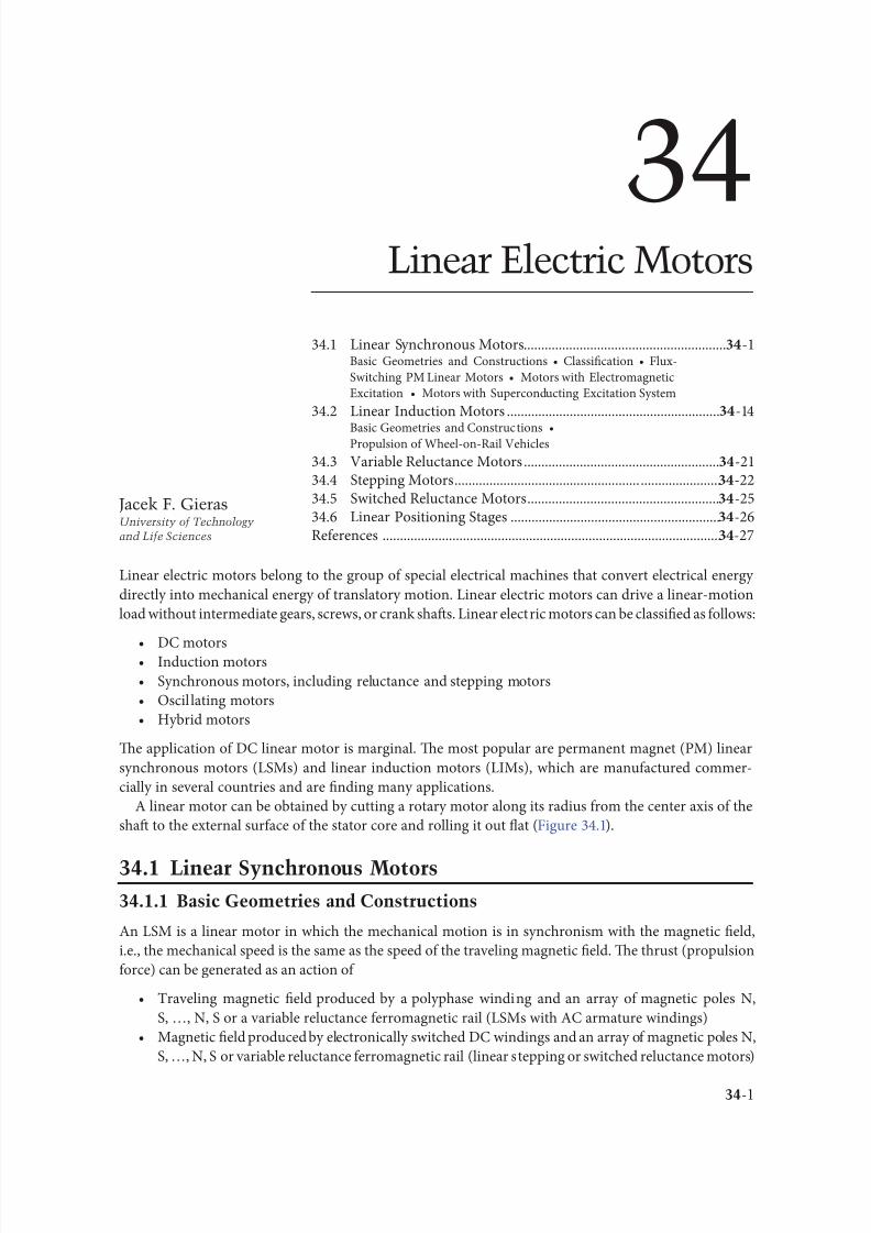
8102019 Power Handbook
httpslidepdfcomreaderfullpower-handbook 1643
34-1
Linear electric motors belong to the group o special electrical machines that convert electrical energy
directly into mechanical energy o translatory motion Linear electric motors can drive a linear-motion
load without intermediate gears screws or crank shafs Linear electric motors can be classi1047297ed as ollows
bull DC motorsbull Induction motors
bull Synchronous motors including reluctance and stepping motors
bull Oscil lating motors
bull Hybrid motors
Te application o DC linear motor is marginal Te most popular are permanent magnet (PM) linear
synchronous motors (LSMs) and linear induction motors (LIMs) which are manuactured commer-
cially in several countries and are 1047297nding many applications
A linear motor can be obtained by cutting a rotary motor along its radius rom the center axis o the
shaf to the external surace o the stator core and rolling it out 1047298at (Figure 341)
341 Linear Synchronous Motors3411 Basic Geometries and Constructions
An LSM is a linear motor in which the mechanical motion is in synchronism with the magnetic 1047297eld
ie the mechanical speed is the same as the speed o the traveling magnetic 1047297eld Te thrust (propulsion
orce) can be generated as an action o
bull raveling magnetic 1047297eld produced by a polyphase winding and an array o magnetic poles N
S hellip N S or a variable reluctance erromagnetic rail (LSMs with AC armature windings)
bull Magnetic 1047297eld produced by electronically switched DC windings and an array o magnetic poles N
S hellip N S or variable reluctance erromagnetic rail (linear stepping or switched reluctance motors)
34Linear Electric Motors
341 Linear Synchronous Motors -1Basic Geometries and Constructions bull Classi1047297cation bull Flux-
Switching PM Linear Motors bull Motors with Electromagnetic
Excitation bull Motors with Superconducting Excitation System
342 Linear Induction Motors -14
Basic Geometries and Constructions bullPropulsion o Wheel-on-Rail Vehicles
343 Variable Reluctance Motors -21344 Stepping Motors -22345 Switched Reluctance Motors -25346 Linear Positioning Stages -26Reerences -27
Jacek F GierasUniversity of Technology
and Life Sciences
8102019 Power Handbook
httpslidepdfcomreaderfullpower-handbook 1743
34-2 Electric Power Generation Transmission and Distribution
Te part producing the traveling magnetic 1047297eld is called the armature or orcer Te part that provides
the DC magnetic 1047298ux or variable reluctance is called the 1047297eld excitation system (i the excitation system
exists) or salient-pole rail reaction rail or variable reluctance platen Te terms primary and secondary
should rather be avoided as they are only justi1047297ed or LIMs [6] or transormers Te operation o an
LSM does not depend on which part is movable and which one is stationary
raditionally AC polyphase synchronous motors are motors with DC electromagnetic excitation the
propulsion orce o which has two components (1) due to the traveling magnetic 1047297eld and DC currentmagnetic 1047298ux (synchronous component) and (2) due to the traveling magnetic 1047297eld and variable reluc-
tance in d - and q-axes (reluctance component) Replacement o DC electromagnets with PMs is common
except or LSMs or magnetically levitated vehicles PM brushless LSMs can be divided into two groups
bull PM LSMs in which the input current waveorms are sinusoidal and produce a traveling magnetic
1047297eld
bull PM DC linear brushless motors (LBMs) with position eedback in which the input rectangular
or trapezoidal current waveorms are precisely synchronized with the speed and position o the
moving part
Construction o magnetic and electric circuits o LSMs belonging to both groups is the same LSMs can
be designed as 1047298at motors (Figure 342) or tubular motors (Figure 343) In DC brushless motors theinormation about the position o the moving part is usually provided by an absolute position sensor
Tis control scheme corresponds to an electronic commutation unctionally equivalent to the mechani-
cal commutation in DC commutator motors Tereore motors with square (trapezoidal) current wave-
orms are called DC brushless motors
Instead o DC or PM excitation the difference between the d - and q-axes reluctances and the traveling
magnetic 1047297eld can generate the reluctance component o the thrust Such a motor is called the AC vari-
able reluctance LSM Different reluctances in the d - and q-axes can be created by making salient erro-
magnetic poles using erromagnetic and nonerromagnetic materials or using anisotropic erromagnetic
materials Te operation o LBMs can be regarded as a special case o the operation o LSMs
1
1
2
2
x
x
v
v
z
z
y
(a)
(b)
y
0
0
1
1
2
2 x
xv
z z
v g
y y
0
0
1 2
21
y
v 0 x
z
d
g 1
g 2
x
z
y
v
0
Evolution o a rotary induction motor (a) solid-rotor induction motor into a 1047298at single-sided LIM
and (b) hollow-rotor induction motor into a 1047298at double-sided LIM 1 primary 2 secondary
8102019 Power Handbook
httpslidepdfcomreaderfullpower-handbook 1843
34-3Linear Electric Motors
In the case o LSMs operating on the principle o the traveling magnetic 1047297eld the speed v o the mov-
ing part is equal to synchronous speed v s ie
v v s= = =2 τ ω
πτ
(341)
Te synchronous speed v s o the traveling magnetic 1047297eld depends only on the input requency (angular
input requency ω = 2π ) and pole pitch τ It does not depend on the number o poles 2 p
As or any other linear-motion electrical machine the useul orce (thrust) F x is directly proportional
to the output power P out and inversely proportional to the speed v = v s ie
F
P
v x
out
s
=
(342)
Flat three-phase PM linear motors (Photo courtesy o Kollmorgen Radord VA)
ubular PM LSM Moving rod (reaction rail) contains circular PMs (Photo courtesy o Caliornia
Linear Drives Carlsbad CA)
8102019 Power Handbook
httpslidepdfcomreaderfullpower-handbook 1943
34-4 Electric Power Generation Transmission and Distribution
Direct electromechanical drives with LSMs or actory automation systems can achieve speeds exceeding
600 mmin = 36 kmh and acceleration o up to 360 ms2 [7] Te thrust density ie thrust per active sur-
ace 2 pτLi where Li is the effective width o the stack
F
p Lx
x
i
=2
(Nm2
τ)
(343)
o LSMs is higher than that o LIMs (Figure 344)
Te polyphase (usually three-phase) armature winding can be distributed in slots made in the orm
o concentrated-parameter coils or made as a coreless (air-cored) winding layer PMs are the most popu-
lar 1047297eld excitation systems or short traveling distances (less than 10 m) or example actory transporta-
tion or automation systems A long PM rail would be expensive Electromagnetic excitation is used in
high-speed passenger transportation systems operating on the principle o magnetic levitation (maglev)
Te German system ransrapid uses vehicle-mounted steel core excitation electromagnets and station-
ary slotted armatures Japanese MLX001 test train sets use onboard superconducting (SC) air-cored
electromagnets and a stationary three-phase air-cored armature winding distributed along the guide-
way (Yamanashi Maglev est Line)
3412 Classi1047297cation
LSMs can be classi1047297ed according to whether they are
bull Flat (planar) or tubular (cylindrical)
bull Single sided or double sided
bull Slotted or slotless
0
10000
20000
30000
40000
50000
60000
0 2000 4000 6000 8000 10000 12000 14000
Trust N
T h r u s t d e n s i t y N m 2
LSM OC
LSM WC
LSM AC
LSM NC
LIM NC
Comparison o thrust density or single-sided LIMs and LSMs AC air cooling NC natural cool-
ing OC oil cooling WC water cooling (From Gieras JF Status o linear motors in the United States International
Symposium on Linear Drives or Industry Applications (LDIArsquo03) Birmingham UK pp 169ndash176 2003)
8102019 Power Handbook
httpslidepdfcomreaderfullpower-handbook 2043
34-5Linear Electric Motors
bull Iron cored or air cored
bull ransverse 1047298ux or longitudinal 1047298ux
Te topologies mentioned earlier are possible or nearly all types o excitation systems LSMs operating
on the principle o the traveling magnetic 1047297eld can have the ollowing excitation systems
bull PMs in the reaction railbull PMs in the armature (passive reaction rail)
bull Electromagnetic excitation system (with winding)
bull SC excitation system
bull Passive reaction rail with saliency and neither PMs nor windings (variable reluctance motors)
LSMs with electronically switched DC armature windings are designed either as linear stepping motors
or linear switched reluctance motors
34121 PM Motors with Active Reaction Rail
Figure 345a shows a single-sided 1047298at LSM with the armature winding located in slots and surace PMs
Figure 345b shows a similar motor with buried-type PMs In surace arrangement o PMs the yoke(back iron) o the reaction rail is erromagnetic and PMs are magnetized in the normal direction (per-
pendicular to the active surace) Buried PMs are magnetized in the direction o the traveling magnetic
1047297eld and the yoke is nonerromagnetic or example made o aluminum (Al) Otherwise the bottom
leakage 1047298ux would be greater than the linkage 1047298ux as shown in Figure 346 Te same effect occurs in
buried-type PM rotors o rotary machines in which the shaf must also be nonerromagnetic [239]
Te so-called Halbach array o PMs also does not require any erromagnetic yoke and excites stronger
magnetic 1047298ux density and closer to the sinusoids than a conventional PM array Te key concept o the
Halbach array is that the magnetization vector should rotate as a unction o distance along the array
(Figure 347)
It is recommended that a PM LSM be urnished with a damper A rotary synchronous motor has a cage
damper winding embedded in pole shoe slots When the speed is different rom the synchronous speed
electric currents are induced in damper circuits Te action o the armature magnetic 1047297eld and damper
currents allows or asynchronous starting damps the oscillations and helps to return to synchronous
operation when the speed decreases or increases Also a damper circuit reduces the backward-traveling
magnetic 1047297eld It would be rather difficult to urnish PMs with a cage winding so that the damper o PM
LSMs has the orm o an Al cover (Figure 348a) or solid steel pole shoes (Figure 348b) In addition steel
pole shoes or Al cover (shield) can protect brittle PMs against mechanical damage
Te detent orce ie attractive orce between PMs and the armature erromagnetic teeth orce ripple
and some higher-space harmonics can be reduced with the aid o skewed assembly o PMs Skewed PMs
can be arranged in one row (Figure 349a) two rows (Figure 349b) or even more rows
1 3
(a) (b)
N
S
τ τ
S
N
1 2 3
N S
τ τ
S N
Single-sided 1047298at PM LSMs with slotted armature core and (a) surace PMs and (b) buried PMs
1 PM 2 mild steel pole 3 yoke
8102019 Power Handbook
httpslidepdfcomreaderfullpower-handbook 2143
34-6 Electric Power Generation Transmission and Distribution
(a)
(b)
Magnetic 1047298ux distribution in the longitudinal sections o buried-type PM LSMs (a) nonerromag-
netic yoke and (b) erromagnetic yoke (back iron)
1
2
Double-sided LSM with Halbach array o PMs 1 PMs 2 coreless armature winding
2
2
3(a)
(b)
3
1
1
Dampers o surace-type PM LSMs (a) Al cover (shield) and (b) solid steel pole shoes 1 PM
2 damper 3 yoke
8102019 Power Handbook
httpslidepdfcomreaderfullpower-handbook 2243
34-7Linear Electric Motors
Speci1047297cation data o 1047298at single-sided PM LBMs manuactured by Anorad are shown in able 341 [1]
and motors manuactured by Kollmorgen are shown in able 342 [11] Te temperature 25degC 125degC
or 130degC or the thrust current resistance and power loss is the temperature o the armature winding
Te electromotive orce (EMF) constant kE in ables 341 and 342 or sinusoidal operation is de1047297ned
according to the equation expressing the EMF (induced voltage) excited by PMs without the armature
reaction ie
E k v E s=
(344)
where v s is the synchronous speed according to Equation 341 Tus the armature constant kE multiplied
by the synchronous speed v s gives the EMF E
S SN N N N N N
N N N N N N
N N N N N N
S S S S
S S S S S S
S
(b)
(a)
S S S S S
Skewed PMs in 1047298at LSMs (a) one row and (b) two rows
Flat Tree-Phase Single-Sided PM LBMs with Natural Cooling Systems
Manuactured by Anorad Hauppauge NY
Parameter LCD--1 LCD--2-P LCD--3-P LCD--4-P
Continuous thrust at 25degC N 163 245 327 490
Continuous current at 25degC A 42 63 85 127
Continuous thrust at 125degC N 139 208 277 416
Continuous current at 125degC A 36 54 72 108
Peak thrust (025 s) N 303 455 606 909
Peak current (025 s) A 92 138 184 276
Peak orce (10 s) N 248 373 497 745
Peak current (10 s) A 73 110 147 220Continuous power losses at 125degC W 58 87 115 173
Armature constant kE Vsm 129
Trust constant (three phases) kF NA 386
Resistance per phase at 25degC Ω 32 22 16 11
Inductance mH 143 95 71 48
PM pole pitch mm 2345
Maximum winding temperature degC 125
Armature assembly mass kg 18 24 36 48
PM assembly mass kgm 64
Normal attractive orce N 1036 1555 2073 3109
8102019 Power Handbook
httpslidepdfcomreaderfullpower-handbook 2343
34-8 Electric Power Generation Transmission and Distribution
Te thrust constant kF in ables 341 and 342 is de1047297ned according to the simpli1047297ed equation or the
developed electromagnetic thrust ie
F k I dx F a= cos Ψ
(345)
or a sinusoidally excited LSM with equal reluctances in the d - and q-axes and or the angle between the
armature current I a and the q-axis Ψ = 0deg (cos Ψ = 1) Tus the thrust constant kF times the armature
current I a gives the electromagnetic thrust developed by the LSM
Double-sided 1047298at PM LSMs consist o two external armature systems and one internal excitation sys-
tem (Figure 3410a) or one internal armature system and two external excitation systems (Figure 3410b)
In the second case a linear Grammersquos armature winding can be used
In slotless motors the primary winding is uniormly distributed on a smooth armature core or does
not have any armature core Slotless PM LSMs are detent orcendashree motors provide lower torque ripple
and at high input requency can achieve higher efficiency than slotted LSMs On the other hand larger
nonerromagnetic air gap requires more PM material and the thrust density (thrust per mass or volume)
is lower than that o slotted motors (able 343) Te input current is higher as synchronous reactances
Flat Tree-Phase Single-Sided PM LBMs with Natural Cooling Systems
Manuactured by Kollmorgen Radord VA
Parameter IC11-030 IC11-050 IC11-100 IC11-200
Continuous thrust at 130degC N 150 275 600 1260
Continuous current at 130degC A 40 44 48 50
Peak thrust N 300 500 1000 2000
Peak current A 79 79 79 79
Continuous power losses at 130degC W 64 106 210 418
Armature constant at 25degC kE Vsm 309 514 1028 2057
Trust constant (three phases) at 25degC kF NA 378 629 1259 2519
Resistance line to line at 25degC Ω 19 26 44 80
Inductance line to line mH 173 278 541 1066
Electrical time constant ms 89 105 123 134
Termal resistance winding to external
structure degCW
164 099 050 025
Maximum winding temperature degC 130
Armature assembly mass kg 20 32 62 122PM assembly mass kgm 55 76 128 269
Normal attractive orce N 1440 2430 4900 9850
(a)
N S N SN S N S
N S N SN S N S
(b)
Double-sided 1047298at PM LSMs with (a) two external armature systems and (b) one internal armature
system
8102019 Power Handbook
httpslidepdfcomreaderfullpower-handbook 2443
34-9Linear Electric Motors
in the d - and q-axes can decrease to a low undesired value due to the absence o teeth Figure 3411a
shows a single-sided 1047298at slotless motor with armature core and Figure 3411b shows a double-sided slot-
less motor with inner air-cored armature winding (moving coil motor)
able 344 contains perormance speci1047297cations o double-sided PM LBMs with inner three-phase air-
cored armature winding manuactured by rilogy Systems Corporation Webster X (Figure 3412)
N
(a) (b)
S N S N S N S
S N NS
Flat slotless PM LSMs (a) single-sided with armature core and (b) double-sided with inner air-
cored armature winding
Slotted versus Slotless LSMs
Quantity Slotted LSM Slotless LSM
Higher thrust density X
Higher efficiency in the lower speed range X
Higher efficiency in the higher speed range x
Lower input current X
Less PM material X
Lower winding cost x
Lower thrust pulsations x
Lower acoustic noise x
Flat Double-Sided PM LBMs with Inner Tree-Phase Air-Cored Series-Coil
Armature Winding Manuactured by rilogy Systems Corporation Webster X
Parameter 310-2 310-4 310-6
Continuous thrust N 1112 2091 3149
Continuous power or sinusoidal operation W 87 152 230
Peak thrust N 356 712 1068
Peak power W 900 1800 2700
Peakcontinuous current A 10028 10026 10026
Trust constant kF or sinusoidal operation NA 400 800 1200
Trust constant kF or trapezoidal operation with Hallsensors NA
351 725 1095
Resistance per phase Ω 86 172 258
Inductance plusmn05 mH 60 120 180
Heat dissipation constant or natural cooling WdegC 110 201 301
Heat dissipation constant or orced air cooling WdegC 130 240 355
Heat dissipation constant or liquid cooling WdegC 154 285 421
Number o poles 2 4 6
Coil length mm 1422 2642 3861
Coil mass kg 055 103 153
Mass o PM excitation systems kgm 1267 or 838
8102019 Power Handbook
httpslidepdfcomreaderfullpower-handbook 2543
34-10 Electric Power Generation Transmission and Distribution
By rolling a lat LSM around the axis parallel to the direction o the traveling magnetic ield
ie parallel to the direction o thrust a tubular (cylindrical) LSM can be obtained (Figure 3413) A
tubular PM LSM can also be designed as a double-sided motor or slotless motor
ubular single-sided LSMs LinMoreg with movable internal PM excitation system (slider) and stationaryexternal armature are manuactured by Sulzer Electronics AG Zurich Switzerland (able 345) All active
motor parts bearings position sensors and electronics have been integrated into a rigid metal cylinder [14]
LinMotreg is a registered trademark o Sulzer Electronics AG Zuumlrich Switzerland
(b)(a)
N S N S N S
N S N S N S
N S N S
SNN S
Single-sided slotted tubular PM LSMs (a) with external armature system and (b) with external
excitation system
Data o ubular LSMs LinMotreg Manuactured by Sulzer Electronics AG Zuumlrich Switzerland
Parameter P01 23 times 80 P01 23 times 160 P01 37 times 120 P01 37 times 240
Number o phases 2
PMs NdFeB
Maximum stroke m 0210 0340 1400 1460Maximum orce N 33 60 122 204
Maximum acceleration ms2 280 350 247 268
Maximum speed ms 24 42 40 31
Stator (armature) length m 0177 0257 0227 0347
Stator outer diameter mm 23 23 37 37
Stator mass kg 0265 0450 0740 1385
Slider diameter mm 12 12 20 20
Maximum temperature o the armature winding degC 90
Flat double-sided PM LSM with inner moving coil (Photo courtesy o rilogy Systems Webster X)
8102019 Power Handbook
httpslidepdfcomreaderfullpower-handbook 2643
34-11Linear Electric Motors
All the aorementioned PM LSMs are motors with longitudinal magnetic 1047298ux the lines o which lie
in the plane parallel to the direction o the traveling magnetic 1047297eld LSMs can also be designed as trans-
verse magnetic 1047298ux motors in which the lines o magnetic 1047298ux are perpendicular to the direction o the
traveling 1047297eld Figure 3414a shows a single-sided transverse 1047298ux LSM in which PMs are arranged in two
rows A pair o parallel PMs creates a two pole 1047298ux excitation system A double-sided con1047297guration o
transverse 1047298ux motor is possible however it is complicated and expensive (Figure 3414b)
34122 PM Motors with Passive Reaction Rail
Te drawback o PM LSMs is the large amount o PM material that must be used to design the excitation
system Normally expensive rare-earth PMs are requested I a small PM LSM uses say 10 kg o NdFeB
per 1 m o the reaction rail and 1 kg o good-quality NdFeB costs US$ 130 the cost o the reaction rail
without assembly amounts to US$ 1300 per 1 m Tis price cannot be acceptable or example in pas-
senger transportation systems
A cheaper solution is to apply the PM excitation system to the short armature that magnetizes the
long reaction rail and creates magnetic poles in it Such a linear motor is called the homopolar LSM
Te homopolar LSM as described in [517] is a double-sided AC linear motor that consists o two
polyphase armature systems connected mechanically and magnetically by a erromagnetic U-type yoke
(Figure 3415) Each armature consists o a typical slotted linear motor stack with polyphase armature
winding and PMs located between the stack and U-type yoke Since the armature and excitation systems
are combined together the armature stack is oversized as compared with a conventional steel-cored LSM
Te PMs can also be replaced by electromagnets [1719] Te variable reluctance reaction rail is passive
Te saliency is created by using erromagnetic (solid or laminated) cubes separated by a nonerromag-netic material Te reaction rail poles are magnetized by the armature PMs through the air gap Te trav-
eling magnetic 1047297eld o the polyphase armature winding and salient poles o the reaction rail produce the
thrust Such a homopolar LSM has been proposed or the propulsion o maglev trains o Swissmetro [17]
Further simpli1047297cation o the double-sided con1047297guration can be made to obtain a single-sided PM
LSM shown in Figure 3416
3413 Flux-Switching PM Linear Motors
Large gantry systems and machining centers require powerul linear motors preerably with PM-ree
reaction rail Siemens 1FN6 PM LSMs with a magnet-ree reaction rail belong to the group o the so
5
(a) (b)
5
N S
N
N
3
4
4
3
2
6
1
3
6
1
6
1
i
S
2
2
N
N
SNN
S
ransverse 1047298ux PM LSM (a) single-sided and (b) double-sided 1 armature winding 2 armature
laminated core 3 PM 4 back erromagnetic core 5 magnetic 1047298ux 6 armature current
8102019 Power Handbook
httpslidepdfcomreaderfullpower-handbook 2743
34-12 Electric Power Generation Transmission and Distribution
called 1047298ux-switching PM machines [1016] Te armature system is air cooled degree o protection IP23
class o insulation F line voltage rom 400 to 480 V rated thrust rom 235 to 2110 N maximum veloc-
ity at rated thrust rom 170 to 540 mmin (able 346) overload capacity 38 o rated thrust modular
type construction [20] Tese LSMs operate with Siemens Sinamics or Simodrive solid-state converters
and external encoders According to Siemens [20] these new LSMs produce thrust orces and velocities
equivalent to competitive classical models or light-duty machine tool machine accessory and material
handling applications
2 3 244 1
N
S
S
N
N
S
S
N
5
Single-sided PM LSM with a passive reaction rail 1 PM 2 armature winding 3 armature stack
4 yoke 5 erromagnetic reaction rail
1
1
2 343
5
Fe Fe Fe Fe
Double-sided homopolar PM LSM with passive reaction rail 1 PM 2 armature winding
3 armature stack 4 yoke 5 reaction rail
Speci1047297cations o 1FN6 PM LSMs Manuactured by Siemens Erlangen Germany
Armature Unit Rated Trust N Max Trust N
Max Speed at
Rated Trust
mmin
Max Speed at
Max Trust
mmin
Rated
Current A Max Current A
1FN6008-1LC17 235ndash350 900 263 103 17ndash26 90
1FN6008-1LC37 235ndash350 900 541 224 35ndash53 180
1FN6016-1LC30 470ndash710 1800 419 176 54ndash80 280
1FN6016-1LC17 935ndash1400 3590 263 101 70ndash105 360
1FN6024-1LC12 705ndash1060 2690 176 69 35ndash53 180
1FN6024-1LC20 705ndash1060 2690 277 114 54ndash80 280
1FN6024-1LG10 2110ndash3170 8080 172 62 105ndash160 540
1FN6024-1LG17 2110ndash3170 8080 270 102 162ndash243 840
Source Synchronous Linear Motor 1FN6 Te Electrical Gear Rack Siemens AG Industry Sector Drive echnologies
Motion Control Erlangen Germany 2008
8102019 Power Handbook
httpslidepdfcomreaderfullpower-handbook 2843
34-13Linear Electric Motors
Te magnet-ree reaction rail is easy to install and does not require the saety considerations o stan-
dard PM reaction rails Without PMs there is no problem with errous chips and other debris beingattracted to these sections Maintenance becomes a simple matter o installing a wiper or brush on the
moving part o the slide
Te 1047298ux-switching LSM comprises an armature section that is equipped with coils and PMs as well
as a nonmagnetic toothed reaction rail section (Figure 3417) Te key design innovation is an LSM in
which PMs are integrated directly into the lamination o the armature core along with the individual
windings or each phase Both magnitudes and polarities o the linkage 1047298ux in the armature winding
vary periodically along with the reaction rail movement Te magnetic 1047298ux between the armature core
and steel reaction rail is controlled by switching the three-phase armature currents according to a desig-
nated algorithm Te passive reaction rail consists o milled steel with poles (teeth) and is much simpler
to manuacture
3414 Motors with Electromagnetic Excitation
Te electromagnetic excitation system o an LSM is similar to the salient-pole rotor o a rotary
synchronous motor Figure 3418 shows a 1047298at single-sided LSM with salient erromagnetic poles and
DC 1047297eld excitation winding Te poles and pole shoes can be made o solid steel laminated steel or sin-
tered powder I the electromagnetic excitation system is integrated with the moving part the DC cur-
rent can be delivered with the aid o brushes and contact bars inductive power transer (IP) systems
linear transormers or linear brushless exciters
A AB BC C
1
2
3
4
5
v
τ2
τ1
Construction o 1047298ux-switching LSM with PM-ree reaction rail 1 laminated armature core
2 PM 3 armature coil (phase C) 4 toothed passive steel reaction rail 5 linkage magnetic 1047298ux (phase A is on)
1
3
τ τ
2
S
d d q q q
4
N
Electromagnetic excitation system o a 1047298at single-sided iron-cored LSM 1 salient pole 2 DC
excitation winding 3 erromagnetic rail (yoke) 4 armature system
8102019 Power Handbook
httpslidepdfcomreaderfullpower-handbook 2943
34-14 Electric Power Generation Transmission and Distribution
LSMs with electromagnetic excitation (wound-1047297eld reaction rail) are used in German ransrapid
maglev train (Figure 3419)
3415 Motors with Superconducting Excitation System
In large-power LSMs the electromagnets with erromagnetic core that produce the excitation 1047298ux can
be replaced by coreless SC electromagnets Since the magnetic 1047298ux density produced by the SC electro-
magnet is greater than the saturation magnetic 1047298ux density o the best laminated alloys ( Bsat asymp 24 or
cobalt alloy) there is no need to use the armature erromagnetic core An LSM with SC 1047297eld excitation
system is a totally air-cored machine (Figure 3420)
Experimental maglev trains on the Yamanashi Maglev est Line (YML) in Yamanashi Preecture(west rom okyo) Japan are driven by air-cored LSMs with SC excitation systems ( Figure 3421)
342 Linear Induction Motors
LIMs have ound the widest prospects or applications in transportation systems beginning with electri-
cal traction on small passenger or material supply cars (used at airports exhibitions electrohighways
elevators) and ending with pallet transportation waer transportation belt conveyors transportation
systems o bulk materials etc Te second important place or LIM applications is in industry ie man-
uacturing processes (machine tools hammers presses mills separators automated manuacturing systems
strip tensioners textile shuttles index tables turntables disk saws or wood sliding doors robots etc)
ransrapid 09 maglev train driven by LSMs with electromagnetic excitation (Photo courtesy oTyssen ransrapid System GmbH Munich Germany)
1
2A
B
C B
A
A
C
S SN
τ τ τ τ τ
N N
CBA
Tree-phase air-cored LSM with SC excitation system 1 armature coils 2 SC excitation coils
8102019 Power Handbook
httpslidepdfcomreaderfullpower-handbook 3043
34-15Linear Electric Motors
LIMs can also play an important part in industrial investigations and tests or example high acceleration
o model aircraf in aerodynamic tunnels high acceleration o vessels in laboratory pools propulsion o
mixers shakers and vibrators and adjusting xndashy tables and instruments Tere is also a possibility o
using LIMs in consumer electronics (sound and vision equipment knitting machines curtains) and in
offices (transportation o documents letters and cash) Te Handbook o Linear Motor Applications [21]
printed in Japan in 1986 contains about 50 examples o applications o LIMs in operation or in the pro-
cess o implementation
3421 Basic Geometries and Constructions
A LIM can be obtained by cutting in the same way either a cage rotor induction motor or a wound rotor
induction motor Te stator becomes the primary and the rotor becomes the secondary [12] Te secondary
o a LIM can be simpli1047297ed by using a solid steel core and replacing the cage (ladder) or slip-ring winding with
a high-conductivity nonerromagnetic plate (Al or Cu) Te nonerromagnetic plate is a secondary electric
circuit with distributed parameters and the erromagnetic core is a conductor both or the magnetic 1047298ux
and the electric current It does not matter rom the principle o operation point o view which part (primary
or secondary) is in motion Tus the 1047298at single-sided LIM can be obtained rom a solid rotor induction
motor (Figure 341a) and the 1047298at double-sided LIM can be obtained rom a hollow-rotor induction motor
with wound external and internal stator (Figure 341b) In a double-sided LIM the secondary erromagneticcore is not necessary since the magnetic 1047298ux excited by one o the primary windings afer passing through
the air gaps and nonerromagnetic secondary is then closed up by the core o the second primary unit
Teoretically a double-sided LIM with primary windings located on two cores in comparison with a
single-sided LIM exciting the same MMF has twice the air gap magnetic 1047298ux density Tereore the thrust
o such a motor is our times greater assuming the same dimensions I only one primary core is wound
the output parameters o a double-sided LIM are the same as those or a single-sided LIM with laminated
secondary back iron Te undamental advantage o double-sided LIMs is the elimination o the normal
attractive orce between the primary and the secondary because the secondary is usually nonerromagnetic
Flat LIMs can have primary cores consisting o an array o cores arranged in parallel at appropri-
ate distances and connected magnetically by additional yokes perpendicular to the direction o the
YML in Yamanashi Preecture (near okyo) Japan YML maglev trains use air-cored LSMs
with SC excitation system (Photo courtesy o Central Japan Railway Company and Railway echnical Research
Institute okyo Japan)
8102019 Power Handbook
httpslidepdfcomreaderfullpower-handbook 3143
34-16 Electric Power Generation Transmission and Distribution
traveling 1047297eld A magnetic circuit designed in such a way makes it possible to apply two windings in
general multiphase windings with perpendicular conductors as shown in Figure 3422 Adjusting the
current in each winding the secondary can be moved in two perpendicular directions and can be posi-
tioned at any point o the xndashy plane A 1047298at LIM with two degrees o reedom (DOFs) can be designed both
as single-sided and double-sided machines
By rolling a 1047298at single-sided or double-sided LIM around the axis parallel to the direction o the travel-
ing magnetic 1047297eld ie parallel to the direction o the thrust a tubular motor can be obtained (Figure 3423)
A tubular (cylindrical) LIM similar to a 1047298at LIM can be designed both as single-sided and double-
sided machines and can have a square or rectangular cross section as in Figure 3424 Tere are possible
Te primary o a 1047298at LIM with two DOFs
g
g
g 1
g 2
(c)
(b)
(a)
d
v
v
v
1
1
1 1
1
1
2
2
2
2
2
2
ubular LIMs (a) single-sided with an external short primary (b) single-sided with an external
short secondary and (c) double-sided with short primary 1 primary 2 secondary
8102019 Power Handbook
httpslidepdfcomreaderfullpower-handbook 3243
34-17Linear Electric Motors
con1047297gurations other than that in Figure 3423 regarding the length o the secondary with respect to thelength o the primary
All the aorementioned LIMs are motors with longitudinal magnetic 1047298ux ie the lines o magnetic
1047298ux lie in the plane parallel to the direction o the traveling magnetic 1047297eld A LIM can also be designed
in such a way as to obtain magnetic 1047298ux lines perpendicular to the direction o the traveling 1047297eld Such
motors are said to have transverse magnetic 1047298ux (Figure 3425)
Te undamental advantage o a LIM with transverse magnetic 1047298ux in comparison with a LIM with
longitudinal magnetic 1047298ux is the lower magnetizing current necessary due to the shorter magnetic 1047298ux
paths Te signi1047297cant disadvantage is lower thrust A 1047298at LIM with transverse magnetic 1047298ux usually has
a primary winding o concentrated coils located on salient poles
A 1047298at single-sided LIM with transverse 1047298ux can produce not only thrust but also electrodynamic
suspension In the design shown in Figure 3426 the secondary is suspended electrodynamically andpropelled and stabilized laterally by the primary magnetic 1047297eld [8] Te primary magnetic circuit con-
sists o E-shaped laminations assembled in two rows Te short secondary is made o light Al alloy in the
orm o a boat Te lateral sides o the boat are inclined by 60deg with respect to the active surace Such a
shape provides maximum normal repulsive orce and maximum lateral stabilization
According to their geometry the LIMs can be divided into the ollowing groups
bull With movable primary or movable secondary
bull Single sided and double sided
bull Flat and tubular
bull With short primary and short secondary
bull With longitudinal and transverse magnetic 1047298ux
1 2 3 4 1 2 3 4
ubular double-sided LIM with a square cross section 1 primary 2 secondary 3 primary coil
4 internal core
v
v
1 1
1
1
(a)
(b)
22
22
Flat LIM with transverse magnetic 1047298ux and salient poles (a) single-sided and (b) double-sided
1 primary 2 secondary
8102019 Power Handbook
httpslidepdfcomreaderfullpower-handbook 3343
34-18 Electric Power Generation Transmission and Distribution
Te linear speed o a LIM is
v s v s= minus( )1 (346)
where
s is the slip
v s is the synchronous speed according to Equation 341
Neglecting the longitudinal end effect [6] the electromagnetic thrust developed by a LIM can be
expressed in a similar way as or a rotary induction motor ie
F
m
v I
R
sdx
s
= prime( ) prime1
2
2 2
(347)
where
m1 is the number o phases o the primary winding
v s is the synchronous speed according to Equation 341
primeI 2 is the secondary current reerred to the primary system
primeR2 is the secondary resistance reerred to the primary system
s is the slip
Te secondary resistance primeR2 must include the so-called edge effect [6]
3422 Propulsion of Wheel-on-Rail Vehicles
Modern railway systems and electrical traction should meet the ollowing requirements
bull High level o automatization and computerization
bull Propulsion and braking independent o adhesion which in turn is affected 1047297rst o all by climate
and weather
bull Low level o noise sometimes below 70 dB (A)
Flat LIM with transverse magnetic 1047298ux salient poles and nonerromagnetic secondary pro-
pelled suspended and stabilized electrodynamically (From Gieras JF et al Analytical calculation o electro-
dynamic levitation orces in a special-purpose linear induction motor International Electric Machines and Drives
Conerence (IEMDCrsquo11) Niagara Falls Ontario Canada 2011 [on CD-ROM])
8102019 Power Handbook
httpslidepdfcomreaderfullpower-handbook 3443
34-19Linear Electric Motors
bull Ability to cope with high slopes at least 6 and sharp bends with radius o curvature less than 20 m
bull No pollution to natural environment and landscape
bull High reliability
Te congestion problems o big cities should be solved by creating collective transport orms that can be
implemented without affecting a highly populated city For example there are many cities in Italy where
the historical center has remained the same since the Renaissance A heavy railway might be a com-
pletely wrong solution and have a notable impact on the city planning An adequate solution might be
a light railway a people mover with transport capacity o 10000ndash20000 passengers per hour to replace
the traditional transport nets and to integrate the existing railway nets
All the requirements mentioned earlier can be met by using LIMs as propulsion machines Replacing
electrical rotary motors with linear motors in traction drives (electrical locomotives) generally does
not require new tracks but only their adjustment to linear drives Single-sided LIMs (Figure 3427a and b)
are best since the normal attractive orce o these can strengthen the adhesion o wheels and rails
Te air gap is rom 10 to 15 mm Most requently the motor car has two LIMs with short primaries
(Figure 3427a) assembled in series Te double-layer secondary consists o a solid back iron and an Al
cap and is located between the rails Cables or computer communication with the vehicle and quite
ofen collectors or electrical energy delivery to the vehicle are located along the track Tree-phaseLIMs are ed rom variable-voltage variable-requency (VVVF) voltage-source inverters A linear pro-
pulsion system o wheel-on-rail vehicles allows more 1047298exibility (Figure 3428) reducing noise on bends
and wear o the wheels and rails
Double-sided LIMs (Figure 3427c and d) have ound very limited application due to the technical
difficulty o eliminating aults caused by bends in the secondary with primary cores on either side It is
more difficult to keep a small and uniorm air gap in double-sided LIMs than that in single-sided LIMs
Te LIM-driven wheel-on-rail vehicles are built or low velocities ie less than 100 kmh and or
short routes ie less than 50 km (urban transit systems and short-distance trains) At present LIM-
driven trains operate in oronto and Vancouver BC Canada in Detroit MI (Figure 3429) okyo
(Figure 3430) and Osaka Japan and Kuala Lumpur Malaysia
(a) (b)
(c) (d)
LIM-driven wheel-on-rail cars (a) single-sided LIM with short primary mounted on the undercar-
riage (b) single-sided LIM with short secondary mounted on the undercarriage (c) double-sided LIM with short pri-
mary mounted on the undercarriage and (d) double-sided LIM with short secondary mounted on the undercarriage
8102019 Power Handbook
httpslidepdfcomreaderfullpower-handbook 3543
34-20 Electric Power Generation Transmission and Distribution
(a) (b)
Te undercarriage o a wheel-on-rail vehicle (a) rotary motor propulsion and (b) LIM propulsion
Detroit people mover driven by single-sided LIMs
oei Oedo subway line in okyo driven by single-sided LIMs
8102019 Power Handbook
httpslidepdfcomreaderfullpower-handbook 3643
34-21Linear Electric Motors
Te design data o some single-sided traction LIMs are presented in able 347 and double-sided trac-
tion LIMs in able 348
343 Variable Reluctance Motors
Te simplest construction o a variable reluctance LSM or linear reluctance motor (LRM) is that shown
in Figure 3418 with DC excitation winding being removed However the thrust o such a motor wouldbe low as the ratio o d -axis permeance to q-axis permeance is low Better perormance can be obtained
when using 1047298ux barriers [18] or steel laminations [15] o make 1047298ux barriers any nonerromagnetic
materials can be used o obtain high permeance (low reluctance) in the d -axis and low permeance in
the q-axis steel laminations should be oriented in such a way as to create high permeance or the d -axis
magnetic 1047298ux
Figure 3431a shows a variable reluctance platen with 1047298ux barriers and Figure 3431b shows how to
arrange steel laminations to obtain different reluctances in the d - and q-axes Te platen can be com-
posed o segments the length o which is equal to the pole pitchτ Each segment consists o semicircular
lamellas cut out rom electrotechnical sheet A 1047297lling or example epoxy resin is used to make the seg-
ment rigid and robust By putting the segments together a platen o any desired length can be obtained
Design Data o Single-Sided Tree-Phase LIMs or Propulsion o Vehicles
Quantity
LIM
UnitJLMDR ICS KU CIGG GEC
Pullout thrust at requency given
in the ollowing F x
125 90 35 17 07 kN
Input requency 200 400 250 400 600 Hz
Rated phase current V 1 2750 4650 1300 2000 2000 A
Number o poles 2 p 8 6 4 6 4 mdash
Number o turns per phase N 1 128 96 128 108 48 mdash
Equivalent diameter o conductor d 1 mdash 893 528 1115 81 mm
Number o parallel conductors mdash 1 mdash 19 1 mdash
Effective width o primary core Li 023 0216 029 0101 01715 m
Pole pitch τ 027 02868 030 025 020 m
Length o single end connection l e mdash 03483 mdash 02955 03685 m
Coil pitch wc 0225 01673 025 01944 01555 m
Air gap g 150 126 120 150 182 mm
Number o slots z 1( primez 1) 96(106) 72(79) 48(58) 54(61) 36(43) mdash
Width o slot b11 mdash 156 170 150 1308 mm
Width o slot opening b14 mdash 156 mdash 1044 1308 mm
Depth o slot h11 mdash 530 380 3421 6147 mm
Height o yoke h1 y mdash 436 393 7163 500 mm
Conductivity o back iron at 20degC σFe mdash 446 952 446 512 times106 Sm
Conductivity o Al cap at 20degC σ Al mdash 300 303 323 215 times106 Sm
Width o back iron w 03 024 03 0111 01715 m
Tickness o back iron hsec 190 125 250 254 474 mm
Tickness o Al cap d 50 45 50 45(25) 32 mm
Tickness o Al cap behind Fe core t ov 50 170 50 127 32 mm
Width o Al cap 030 032 040 0201 02985 m
JLMDR Japanese Linear Motor Driven Railcar Japan ICS Intermediate Capacity ransit System Canada KU
Kyushu University LIM Japan CIGG Canadian Inst o Guided Ground ransport Canada GEC General
Electric Company United States (z 1 ) is the number o hal 1047297lled slots
8102019 Power Handbook
httpslidepdfcomreaderfullpower-handbook 3743
34-22 Electric Power Generation Transmission and Distribution
344 Stepping Motors
A linear stepping motor has a concentrated armature winding wound on salient poles and PM excitation
rail or variable reluctance platen Te thrust is generated as an action o the armature magnetic 1047298ux and
PM 1047298ux (active platen) or the armature magnetic 1047298ux and salient erromagnetic poles (variable reluc-
tance platen) Stepping motors have no position eedback
Design Data o Double-Sided Tree-Phase LIMs or Propulsion
o Vehicles
Quantity
LIM
UnitGEC LIMVR
Maximum thrust at input requency F x given in the ollowing 085 1668 kN
Input requency 600 1730 Hz
Input phase current I 1 2000 20000 A
Number o poles 2 p 4 10 mdash
Number o turns per phase N 1 144 100 mdash
Diameter o conductor d 1 075 110 mm
Effective width o primary core Li 00869 0254 m
Pole pitch τ 01795 03556 m
Coil pitch wc 005 005 m
Number o slots z 1( primez 1) 36(45) 150(160) mdash
Width o slot b11 137 160 mm
Width o slot opening b14 137 mdash mm
Depth o slot h1 630 mdash mm
Height o yoke h1 y 239 mdash mm
Width o tooth c1 200 77 mm
Resultant air gap 2 g + d 381 38075 mm
Air gap g 2 times 127 2 times 111 mm
Tickness o secondary d 127 15875(hollow) mm
Effective thickness o Al secondary 127 72 mm
Width o secondary w ge03046 mdash m
Conductivity o Al cap at 20degC σ Al asymp2434 asymp240 times106 Sm
GEC General Electric Company United States LIMVR LIM Research Vehicle
Pueblo CO United States (z 1 ) is the number o hal 1047297lled slots
(a) (b)
q q d d d q d q d d
Laminations
τ τ τ τ
Epoxy resin
Variable reluctance LSMs with (a) 1047298ux barriers and (b) steel laminations
8102019 Power Handbook
httpslidepdfcomreaderfullpower-handbook 3843
8102019 Power Handbook
httpslidepdfcomreaderfullpower-handbook 3943
34-24 Electric Power Generation Transmission and Distribution
Tis value is different or ull-step and microstepping drives Te maximum startndashstop speed is the
maximum speed that can be used when starting or stopping the motor without ramping that does not
cause the motor to all out o synchronism or lose steps Te maximum speed is the maximum linear
speed that can be achieved without the motor stalling or alling out o synchronism Te maximum
load mass is the maximum allowable mass applied to the orcer against the scale that does not result in
mechanical damage Te ull-step resolution is the position increment obtained when the currents are
switched rom one winding to the next winding Tis is the typical resolution obtained with ul l-step
drives and it is strictly a unction o the motor construction Te microstepping resolution is the position
increment obtained when the ull-step resolution is divided electronically by proportioning the currents
in the two windings Tis resolution is typically 10ndash250 times smaller than the ull-step resolution [13]
HLSMs are regarded as an excellent solution to positioning systems that require a high accuracy
and rapid acceleration With a microprocessor controlled microstepping mode a smooth operation with
standard resolution o a ew hundred stepsmm can be obtained Te advantages such as high efficiencyhigh throughput mechanical simplicity high reliability precise open-loop operation and low inertia
o the system have made these kind o motors more and more attractive in such applications as actory
automation high speed positioning computer peripherals acsimile machines numerically controlled
machine tools automated medical equipment automated laboratory equipment and welding robots
Tis motor is especially suitable or machine tools printers plotters and computer-controlled material
handling in which a high positioning accuracy and repeatability are the key problems
When two or our orcers mounted at 90deg and a special grooved platen (ldquowaffle platerdquo) are used the
xndashy motion (two DOFs) in a single plane is obtained (Figure 3434)
Speci1047297cation data o the xndashy HLSMs manuactured by Normag Northern Magnetics Inc Santa
Clarita CA are given in able 3410
PM linear stepping motors (Photo courtesy o okyo Aircraf Instrument Co Ltd okyo Japan)
8102019 Power Handbook
httpslidepdfcomreaderfullpower-handbook 4043
34-25Linear Electric Motors
345 Switched Reluctance Motors
Te topology o a linear switched reluctance motor is similar to that o a stepping motor with variable
reluctance platen In addition it is equipped with position sensors Te turn-on and turn-off instant o
the input current is synchronized with the position o the moving part Te thrust is very sensitive to
the turn-on and turn-off instant
In the case o a linear stepping or linear switched reluctance motor the speed v o the moving part is
v v s sw= = τ
(348)
where
sw is the undamental switching requency in one armature phase winding
τ is the pole pitch o the reaction rail
For a rotary stepping or switched reluctance motor sw = 2 pr n where 2 pr is the number o rotor poles and
n is rotational speed in revs
A linear switched reluctance motor has a doubly salient magnetic circuit with a polyphase winding
on the armature Longitudinal and transverse 1047298ux designs are shown in Figure 3435 A linear switched
reluctance motor allows precise speed and position-controlled linear motion at low speeds and is not sub-
ject to design constraints (minimum speed limited by minimum easible pole pitch) o linear AC motors
x
y
12
3
4
1
1
2
2
HLSM with a our-unit orcer to obtain the xndashy motion 1 orcers or the x -direction 2 orcers
or the y -direction 3 platen 4 air pressure
Data o xndashy HLSMs Manuactured by Normag Northern Magnetics Inc
Santa Clarita CA
Parameter 4XY0602-2-0 4XY2002-2-0 4XY2004-2-0 4XY2504-2-0
Number o orcer units per axis 1 1 2 2
Number o phases 2 2 2(4) 2(4)Static thrust N 133 400 980 1330
Trust at 1 ms N 111 311 712 980
Normal attractive orce N 1600 4000 14400 18000
Resistance per phase Ω 29 33 16 19
Inductance per phase mH 15 40 20 23
Input phase current A 20 20 40 40
Air gap mm 002
Maximum temperature degC 110
Mass kg 32 072 20 15
Repeatability mm 000254
Resolution mm 000254
Bearing type Air
8102019 Power Handbook
httpslidepdfcomreaderfullpower-handbook 4143
34-26 Electric Power Generation Transmission and Distribution
346 Linear Positioning Stages
Linear motors are now playing a key role in advanced precision linear positioning Linear precision posi-
tioning systems can be classi1047297ed into open-loop systems with HLSMs and closed-loop servo systems
with LSMs LBMs or LIMs
A PM LSMndashdriven positioning stage is shown in Figure 3436 A stationary base is made o Al steel
ceramic or granite plate It provides a stable precise and 1047298at platorm to which all stationary position-
ing components are attached Te base o the stage is attached to the host system with the aid o mount-
ing screws
Te moving table accommodates all moving positioning components o achieve maximum accelera-
tion the mass o the moving table should be as small as possible and usually Al is used as a lightweight
material A number o mounting holes on the moving table is necessary to 1047297x the payload to the mount-
ing table
Linear bearing rails provide a precise guidance to the moving table A minimum o one bearing rail
is required Linear ball bearing or air bearings are attached to each rail
Te armature o a linear motor is astened to the moving table and reaction rail (PM excitation sys-tem) is built in the base between the rails (Figure 3436)
A linear encoder is needed to obtain precise control o position o the table velocity and acceleration
Te read head o the encoder is attached to the moving table
(a) (b)
3
3
221
1
Linear switched reluctance motor con1047297gurations (a) longitudinal 1047298ux design and (b) transverse
1047298ux design 1 armature winding 2 armature stack 3 platen
12
3
5
4
7
6
8
Linear positioning stage driven by PM LBM 1 base 2 moving table 3 armature o LBM 4 PMs
5 linear bearing 6 encoder 7 cable carrier 8 limit switch (Courtesy o Normag Santa Clarita CA)
8102019 Power Handbook
httpslidepdfcomreaderfullpower-handbook 4243
34-27Linear Electric Motors
Noncontact limit switches ixed to the base provide an overtravel protection and init ial homing
A cable carrier accommodates and routes electrical cables between the moving table and stationary
connector box 1047297xed to the base
An HLSM-driven linear precision stage is o similar construction Instead o PMs between bearing
rails it has a variable reluctance platen HLSMs usually need air bearings and in addition to the electri-
cal cables an air hose between air bearings and the compressor is requiredLinear positioning stages are used in semiconductor technology electronic assembly quality assur-
ance laser cutting optical scanning water jet cutting gantry systems (x y z stages) color printers
plotters and Cartesian coordinate robotics
References
1 Anorad Linear Motors Inormation Brochure Anorad Hauppauge New York 2007 wwwanoradcom
2 Boldea I and Nasar SA Linear Motion Electromagnetic Systems John Wiley amp Sons New York 1985
3 Boldea I and Nasar SA Linear Electric Actuators and Generators Cambridge University Press
New York 2005
4 Compumotor Digiplan Positioning Control Systems and Drives Parker Hanni1047297n CorporationRohnert Park CA 2011
5 Everes W Henneberger G Wunderlich H and Selig A A linear homopolar motor or a trans-
portation system 2nd International Symposium on Linear Drives or Industry Applications (LDIArsquo98)
okyo Japan 1998 pp 46ndash49
6 Gieras JF Linear Induction Drives Clarendon Press Oxord UK 1994
7 Gieras JF Status o linear motors in the United States International Symposium on Linear Drives
or Industry Applications (LDIArsquo03) Birmingham UK 2003 pp 169ndash176
8 Gieras JF Gientkowski Z Mews J and Splawski P Analytical calculation o electrodynamic
levitation orces in a special-purpose linear induction motor International Electric Machines and
Drives Conerence (IEMDCrsquo11) Niagara Falls Ontario Canada 2011 [on CD-ROM]
9 Gieras JF Piech ZJ and omczuk BZ Linear Synchronous Motors ransportation and Automation Systems aylor amp Francis (CRC Press) Boca Raton FL 2011
10 Hoang E Ahmed AHB and Lucidarme J Switching 1047298ux permanent magnet polyphase syn-
chronous machines 7th European Conerence on Power Electronics and Applications (EPErsquo97)
Vol 3 rondheim Norway 1977 pp 903ndash908
11 Kollmorgen Linear Motors Aim to Cut Cost o Semiconductors and Electronics Manuacture
Kollmorgen Radord VA 1997
12 Laithwaite ER A History o Linear Electric Motors Macmillan London UK 1987
13 Linear Step Motor Inormation Brochure okyo Aircraf Instrument Co Ltd okyo Japan
1998
14 LinMot Design Manual Sulzer Electronics Ltd Zuumlrich Switzerland 1999
15 Locci N and Marongiu I Modelling and testing a new linear reluctance motor InternationalConerence on Electrical Machines (ICEMrsquo92) Vol 2 Manchester UK 1992 pp 706ndash710
16 Rauch SE and Johnson LJ Design principles o 1047298ux-switch alternators AIEE rans Part III
74(12) 1261ndash1269 1955
17 Rosenmayr M Casat Glavitsch A and Stemmler H SwissmetromdashPower supply or a high-
power-propulsion system with short stator linear motors 15th International Conerence on
Magnetically Levitated Systems and Linear Drives Maglevrsquo98 Mount Fuji Yamanashi Japan 1998
pp 280ndash286
18 Sanada M Morimoto S and akeda Y Reluctance equalization design o multi 1047298ux barrier con-
struction or linear synchronous reluctance motors 2nd International Symposium on Linear Drives
or Industrial Applications (LDIArsquo98) okyo Japan 1998 pp 259ndash262
8102019 Power Handbook
httpslidepdfcomreaderfullpower-handbook 4343
34-28 Electric Power Generation Transmission and Distribution
19 Seok-Myeong J and Sang-Sub J Design and analysis o the linear homopolar synchronous motor
or integrated magnetic propulsion and suspension 2nd International Symposium on Linear Drives
or Industrial Applications (LDIArsquo98) okyo Japan 1998 pp 74ndash77
20 Synchronous Linear Motor 1FN6 Te Electrical Gear Rack Siemens AG Industry Sector Drive
echnologies Motion Control Erlangen Germany 2008
21 Yamada H Handbook o Linear Motor Applications (in Japanese) Kogyo Chosaki Publishing Cookyo Japan 1986
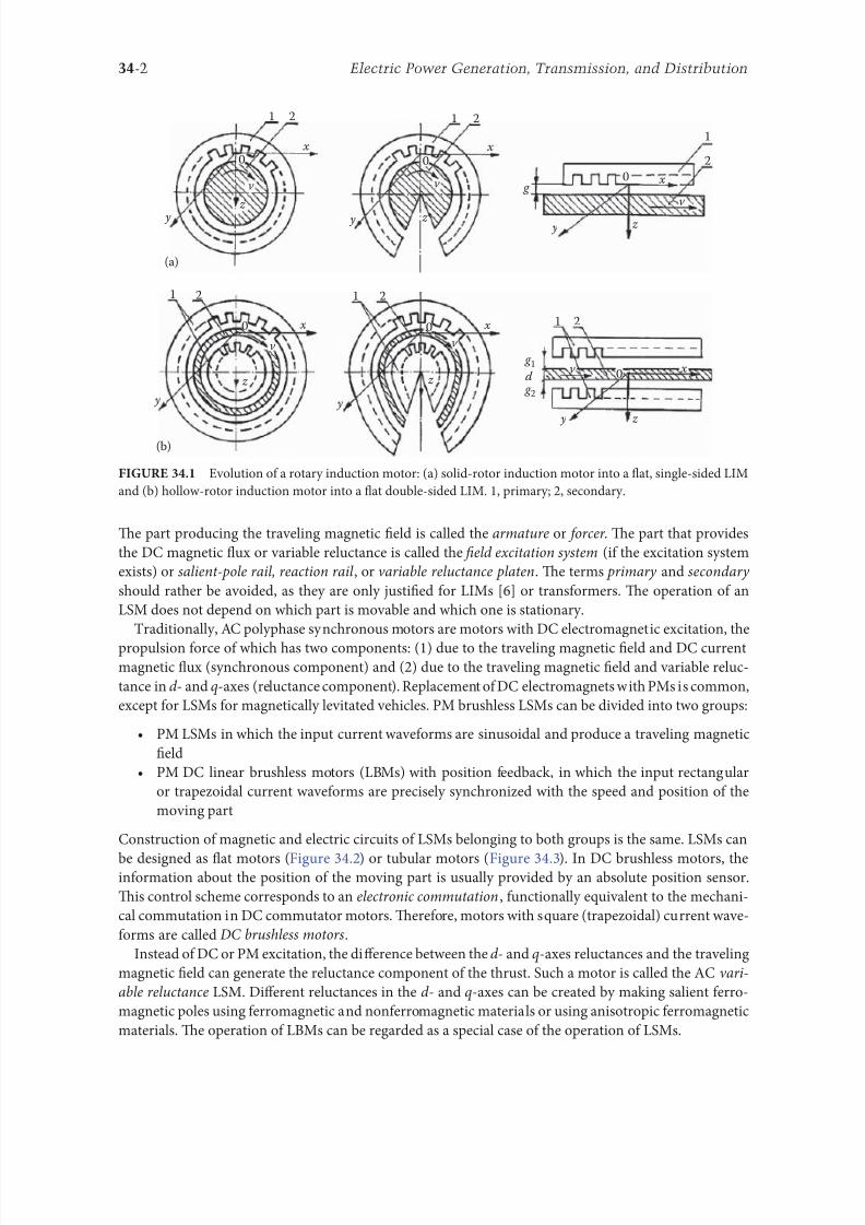
8102019 Power Handbook
httpslidepdfcomreaderfullpower-handbook 1743
34-2 Electric Power Generation Transmission and Distribution
Te part producing the traveling magnetic 1047297eld is called the armature or orcer Te part that provides
the DC magnetic 1047298ux or variable reluctance is called the 1047297eld excitation system (i the excitation system
exists) or salient-pole rail reaction rail or variable reluctance platen Te terms primary and secondary
should rather be avoided as they are only justi1047297ed or LIMs [6] or transormers Te operation o an
LSM does not depend on which part is movable and which one is stationary
raditionally AC polyphase synchronous motors are motors with DC electromagnetic excitation the
propulsion orce o which has two components (1) due to the traveling magnetic 1047297eld and DC currentmagnetic 1047298ux (synchronous component) and (2) due to the traveling magnetic 1047297eld and variable reluc-
tance in d - and q-axes (reluctance component) Replacement o DC electromagnets with PMs is common
except or LSMs or magnetically levitated vehicles PM brushless LSMs can be divided into two groups
bull PM LSMs in which the input current waveorms are sinusoidal and produce a traveling magnetic
1047297eld
bull PM DC linear brushless motors (LBMs) with position eedback in which the input rectangular
or trapezoidal current waveorms are precisely synchronized with the speed and position o the
moving part
Construction o magnetic and electric circuits o LSMs belonging to both groups is the same LSMs can
be designed as 1047298at motors (Figure 342) or tubular motors (Figure 343) In DC brushless motors theinormation about the position o the moving part is usually provided by an absolute position sensor
Tis control scheme corresponds to an electronic commutation unctionally equivalent to the mechani-
cal commutation in DC commutator motors Tereore motors with square (trapezoidal) current wave-
orms are called DC brushless motors
Instead o DC or PM excitation the difference between the d - and q-axes reluctances and the traveling
magnetic 1047297eld can generate the reluctance component o the thrust Such a motor is called the AC vari-
able reluctance LSM Different reluctances in the d - and q-axes can be created by making salient erro-
magnetic poles using erromagnetic and nonerromagnetic materials or using anisotropic erromagnetic
materials Te operation o LBMs can be regarded as a special case o the operation o LSMs
1
1
2
2
x
x
v
v
z
z
y
(a)
(b)
y
0
0
1
1
2
2 x
xv
z z
v g
y y
0
0
1 2
21
y
v 0 x
z
d
g 1
g 2
x
z
y
v
0
Evolution o a rotary induction motor (a) solid-rotor induction motor into a 1047298at single-sided LIM
and (b) hollow-rotor induction motor into a 1047298at double-sided LIM 1 primary 2 secondary
8102019 Power Handbook
httpslidepdfcomreaderfullpower-handbook 1843
34-3Linear Electric Motors
In the case o LSMs operating on the principle o the traveling magnetic 1047297eld the speed v o the mov-
ing part is equal to synchronous speed v s ie
v v s= = =2 τ ω
πτ
(341)
Te synchronous speed v s o the traveling magnetic 1047297eld depends only on the input requency (angular
input requency ω = 2π ) and pole pitch τ It does not depend on the number o poles 2 p
As or any other linear-motion electrical machine the useul orce (thrust) F x is directly proportional
to the output power P out and inversely proportional to the speed v = v s ie
F
P
v x
out
s
=
(342)
Flat three-phase PM linear motors (Photo courtesy o Kollmorgen Radord VA)
ubular PM LSM Moving rod (reaction rail) contains circular PMs (Photo courtesy o Caliornia
Linear Drives Carlsbad CA)
8102019 Power Handbook
httpslidepdfcomreaderfullpower-handbook 1943
34-4 Electric Power Generation Transmission and Distribution
Direct electromechanical drives with LSMs or actory automation systems can achieve speeds exceeding
600 mmin = 36 kmh and acceleration o up to 360 ms2 [7] Te thrust density ie thrust per active sur-
ace 2 pτLi where Li is the effective width o the stack
F
p Lx
x
i
=2
(Nm2
τ)
(343)
o LSMs is higher than that o LIMs (Figure 344)
Te polyphase (usually three-phase) armature winding can be distributed in slots made in the orm
o concentrated-parameter coils or made as a coreless (air-cored) winding layer PMs are the most popu-
lar 1047297eld excitation systems or short traveling distances (less than 10 m) or example actory transporta-
tion or automation systems A long PM rail would be expensive Electromagnetic excitation is used in
high-speed passenger transportation systems operating on the principle o magnetic levitation (maglev)
Te German system ransrapid uses vehicle-mounted steel core excitation electromagnets and station-
ary slotted armatures Japanese MLX001 test train sets use onboard superconducting (SC) air-cored
electromagnets and a stationary three-phase air-cored armature winding distributed along the guide-
way (Yamanashi Maglev est Line)
3412 Classi1047297cation
LSMs can be classi1047297ed according to whether they are
bull Flat (planar) or tubular (cylindrical)
bull Single sided or double sided
bull Slotted or slotless
0
10000
20000
30000
40000
50000
60000
0 2000 4000 6000 8000 10000 12000 14000
Trust N
T h r u s t d e n s i t y N m 2
LSM OC
LSM WC
LSM AC
LSM NC
LIM NC
Comparison o thrust density or single-sided LIMs and LSMs AC air cooling NC natural cool-
ing OC oil cooling WC water cooling (From Gieras JF Status o linear motors in the United States International
Symposium on Linear Drives or Industry Applications (LDIArsquo03) Birmingham UK pp 169ndash176 2003)
8102019 Power Handbook
httpslidepdfcomreaderfullpower-handbook 2043
34-5Linear Electric Motors
bull Iron cored or air cored
bull ransverse 1047298ux or longitudinal 1047298ux
Te topologies mentioned earlier are possible or nearly all types o excitation systems LSMs operating
on the principle o the traveling magnetic 1047297eld can have the ollowing excitation systems
bull PMs in the reaction railbull PMs in the armature (passive reaction rail)
bull Electromagnetic excitation system (with winding)
bull SC excitation system
bull Passive reaction rail with saliency and neither PMs nor windings (variable reluctance motors)
LSMs with electronically switched DC armature windings are designed either as linear stepping motors
or linear switched reluctance motors
34121 PM Motors with Active Reaction Rail
Figure 345a shows a single-sided 1047298at LSM with the armature winding located in slots and surace PMs
Figure 345b shows a similar motor with buried-type PMs In surace arrangement o PMs the yoke(back iron) o the reaction rail is erromagnetic and PMs are magnetized in the normal direction (per-
pendicular to the active surace) Buried PMs are magnetized in the direction o the traveling magnetic
1047297eld and the yoke is nonerromagnetic or example made o aluminum (Al) Otherwise the bottom
leakage 1047298ux would be greater than the linkage 1047298ux as shown in Figure 346 Te same effect occurs in
buried-type PM rotors o rotary machines in which the shaf must also be nonerromagnetic [239]
Te so-called Halbach array o PMs also does not require any erromagnetic yoke and excites stronger
magnetic 1047298ux density and closer to the sinusoids than a conventional PM array Te key concept o the
Halbach array is that the magnetization vector should rotate as a unction o distance along the array
(Figure 347)
It is recommended that a PM LSM be urnished with a damper A rotary synchronous motor has a cage
damper winding embedded in pole shoe slots When the speed is different rom the synchronous speed
electric currents are induced in damper circuits Te action o the armature magnetic 1047297eld and damper
currents allows or asynchronous starting damps the oscillations and helps to return to synchronous
operation when the speed decreases or increases Also a damper circuit reduces the backward-traveling
magnetic 1047297eld It would be rather difficult to urnish PMs with a cage winding so that the damper o PM
LSMs has the orm o an Al cover (Figure 348a) or solid steel pole shoes (Figure 348b) In addition steel
pole shoes or Al cover (shield) can protect brittle PMs against mechanical damage
Te detent orce ie attractive orce between PMs and the armature erromagnetic teeth orce ripple
and some higher-space harmonics can be reduced with the aid o skewed assembly o PMs Skewed PMs
can be arranged in one row (Figure 349a) two rows (Figure 349b) or even more rows
1 3
(a) (b)
N
S
τ τ
S
N
1 2 3
N S
τ τ
S N
Single-sided 1047298at PM LSMs with slotted armature core and (a) surace PMs and (b) buried PMs
1 PM 2 mild steel pole 3 yoke
8102019 Power Handbook
httpslidepdfcomreaderfullpower-handbook 2143
34-6 Electric Power Generation Transmission and Distribution
(a)
(b)
Magnetic 1047298ux distribution in the longitudinal sections o buried-type PM LSMs (a) nonerromag-
netic yoke and (b) erromagnetic yoke (back iron)
1
2
Double-sided LSM with Halbach array o PMs 1 PMs 2 coreless armature winding
2
2
3(a)
(b)
3
1
1
Dampers o surace-type PM LSMs (a) Al cover (shield) and (b) solid steel pole shoes 1 PM
2 damper 3 yoke
8102019 Power Handbook
httpslidepdfcomreaderfullpower-handbook 2243
34-7Linear Electric Motors
Speci1047297cation data o 1047298at single-sided PM LBMs manuactured by Anorad are shown in able 341 [1]
and motors manuactured by Kollmorgen are shown in able 342 [11] Te temperature 25degC 125degC
or 130degC or the thrust current resistance and power loss is the temperature o the armature winding
Te electromotive orce (EMF) constant kE in ables 341 and 342 or sinusoidal operation is de1047297ned
according to the equation expressing the EMF (induced voltage) excited by PMs without the armature
reaction ie
E k v E s=
(344)
where v s is the synchronous speed according to Equation 341 Tus the armature constant kE multiplied
by the synchronous speed v s gives the EMF E
S SN N N N N N
N N N N N N
N N N N N N
S S S S
S S S S S S
S
(b)
(a)
S S S S S
Skewed PMs in 1047298at LSMs (a) one row and (b) two rows
Flat Tree-Phase Single-Sided PM LBMs with Natural Cooling Systems
Manuactured by Anorad Hauppauge NY
Parameter LCD--1 LCD--2-P LCD--3-P LCD--4-P
Continuous thrust at 25degC N 163 245 327 490
Continuous current at 25degC A 42 63 85 127
Continuous thrust at 125degC N 139 208 277 416
Continuous current at 125degC A 36 54 72 108
Peak thrust (025 s) N 303 455 606 909
Peak current (025 s) A 92 138 184 276
Peak orce (10 s) N 248 373 497 745
Peak current (10 s) A 73 110 147 220Continuous power losses at 125degC W 58 87 115 173
Armature constant kE Vsm 129
Trust constant (three phases) kF NA 386
Resistance per phase at 25degC Ω 32 22 16 11
Inductance mH 143 95 71 48
PM pole pitch mm 2345
Maximum winding temperature degC 125
Armature assembly mass kg 18 24 36 48
PM assembly mass kgm 64
Normal attractive orce N 1036 1555 2073 3109
8102019 Power Handbook
httpslidepdfcomreaderfullpower-handbook 2343
34-8 Electric Power Generation Transmission and Distribution
Te thrust constant kF in ables 341 and 342 is de1047297ned according to the simpli1047297ed equation or the
developed electromagnetic thrust ie
F k I dx F a= cos Ψ
(345)
or a sinusoidally excited LSM with equal reluctances in the d - and q-axes and or the angle between the
armature current I a and the q-axis Ψ = 0deg (cos Ψ = 1) Tus the thrust constant kF times the armature
current I a gives the electromagnetic thrust developed by the LSM
Double-sided 1047298at PM LSMs consist o two external armature systems and one internal excitation sys-
tem (Figure 3410a) or one internal armature system and two external excitation systems (Figure 3410b)
In the second case a linear Grammersquos armature winding can be used
In slotless motors the primary winding is uniormly distributed on a smooth armature core or does
not have any armature core Slotless PM LSMs are detent orcendashree motors provide lower torque ripple
and at high input requency can achieve higher efficiency than slotted LSMs On the other hand larger
nonerromagnetic air gap requires more PM material and the thrust density (thrust per mass or volume)
is lower than that o slotted motors (able 343) Te input current is higher as synchronous reactances
Flat Tree-Phase Single-Sided PM LBMs with Natural Cooling Systems
Manuactured by Kollmorgen Radord VA
Parameter IC11-030 IC11-050 IC11-100 IC11-200
Continuous thrust at 130degC N 150 275 600 1260
Continuous current at 130degC A 40 44 48 50
Peak thrust N 300 500 1000 2000
Peak current A 79 79 79 79
Continuous power losses at 130degC W 64 106 210 418
Armature constant at 25degC kE Vsm 309 514 1028 2057
Trust constant (three phases) at 25degC kF NA 378 629 1259 2519
Resistance line to line at 25degC Ω 19 26 44 80
Inductance line to line mH 173 278 541 1066
Electrical time constant ms 89 105 123 134
Termal resistance winding to external
structure degCW
164 099 050 025
Maximum winding temperature degC 130
Armature assembly mass kg 20 32 62 122PM assembly mass kgm 55 76 128 269
Normal attractive orce N 1440 2430 4900 9850
(a)
N S N SN S N S
N S N SN S N S
(b)
Double-sided 1047298at PM LSMs with (a) two external armature systems and (b) one internal armature
system
8102019 Power Handbook
httpslidepdfcomreaderfullpower-handbook 2443
34-9Linear Electric Motors
in the d - and q-axes can decrease to a low undesired value due to the absence o teeth Figure 3411a
shows a single-sided 1047298at slotless motor with armature core and Figure 3411b shows a double-sided slot-
less motor with inner air-cored armature winding (moving coil motor)
able 344 contains perormance speci1047297cations o double-sided PM LBMs with inner three-phase air-
cored armature winding manuactured by rilogy Systems Corporation Webster X (Figure 3412)
N
(a) (b)
S N S N S N S
S N NS
Flat slotless PM LSMs (a) single-sided with armature core and (b) double-sided with inner air-
cored armature winding
Slotted versus Slotless LSMs
Quantity Slotted LSM Slotless LSM
Higher thrust density X
Higher efficiency in the lower speed range X
Higher efficiency in the higher speed range x
Lower input current X
Less PM material X
Lower winding cost x
Lower thrust pulsations x
Lower acoustic noise x
Flat Double-Sided PM LBMs with Inner Tree-Phase Air-Cored Series-Coil
Armature Winding Manuactured by rilogy Systems Corporation Webster X
Parameter 310-2 310-4 310-6
Continuous thrust N 1112 2091 3149
Continuous power or sinusoidal operation W 87 152 230
Peak thrust N 356 712 1068
Peak power W 900 1800 2700
Peakcontinuous current A 10028 10026 10026
Trust constant kF or sinusoidal operation NA 400 800 1200
Trust constant kF or trapezoidal operation with Hallsensors NA
351 725 1095
Resistance per phase Ω 86 172 258
Inductance plusmn05 mH 60 120 180
Heat dissipation constant or natural cooling WdegC 110 201 301
Heat dissipation constant or orced air cooling WdegC 130 240 355
Heat dissipation constant or liquid cooling WdegC 154 285 421
Number o poles 2 4 6
Coil length mm 1422 2642 3861
Coil mass kg 055 103 153
Mass o PM excitation systems kgm 1267 or 838
8102019 Power Handbook
httpslidepdfcomreaderfullpower-handbook 2543
34-10 Electric Power Generation Transmission and Distribution
By rolling a lat LSM around the axis parallel to the direction o the traveling magnetic ield
ie parallel to the direction o thrust a tubular (cylindrical) LSM can be obtained (Figure 3413) A
tubular PM LSM can also be designed as a double-sided motor or slotless motor
ubular single-sided LSMs LinMoreg with movable internal PM excitation system (slider) and stationaryexternal armature are manuactured by Sulzer Electronics AG Zurich Switzerland (able 345) All active
motor parts bearings position sensors and electronics have been integrated into a rigid metal cylinder [14]
LinMotreg is a registered trademark o Sulzer Electronics AG Zuumlrich Switzerland
(b)(a)
N S N S N S
N S N S N S
N S N S
SNN S
Single-sided slotted tubular PM LSMs (a) with external armature system and (b) with external
excitation system
Data o ubular LSMs LinMotreg Manuactured by Sulzer Electronics AG Zuumlrich Switzerland
Parameter P01 23 times 80 P01 23 times 160 P01 37 times 120 P01 37 times 240
Number o phases 2
PMs NdFeB
Maximum stroke m 0210 0340 1400 1460Maximum orce N 33 60 122 204
Maximum acceleration ms2 280 350 247 268
Maximum speed ms 24 42 40 31
Stator (armature) length m 0177 0257 0227 0347
Stator outer diameter mm 23 23 37 37
Stator mass kg 0265 0450 0740 1385
Slider diameter mm 12 12 20 20
Maximum temperature o the armature winding degC 90
Flat double-sided PM LSM with inner moving coil (Photo courtesy o rilogy Systems Webster X)
8102019 Power Handbook
httpslidepdfcomreaderfullpower-handbook 2643
34-11Linear Electric Motors
All the aorementioned PM LSMs are motors with longitudinal magnetic 1047298ux the lines o which lie
in the plane parallel to the direction o the traveling magnetic 1047297eld LSMs can also be designed as trans-
verse magnetic 1047298ux motors in which the lines o magnetic 1047298ux are perpendicular to the direction o the
traveling 1047297eld Figure 3414a shows a single-sided transverse 1047298ux LSM in which PMs are arranged in two
rows A pair o parallel PMs creates a two pole 1047298ux excitation system A double-sided con1047297guration o
transverse 1047298ux motor is possible however it is complicated and expensive (Figure 3414b)
34122 PM Motors with Passive Reaction Rail
Te drawback o PM LSMs is the large amount o PM material that must be used to design the excitation
system Normally expensive rare-earth PMs are requested I a small PM LSM uses say 10 kg o NdFeB
per 1 m o the reaction rail and 1 kg o good-quality NdFeB costs US$ 130 the cost o the reaction rail
without assembly amounts to US$ 1300 per 1 m Tis price cannot be acceptable or example in pas-
senger transportation systems
A cheaper solution is to apply the PM excitation system to the short armature that magnetizes the
long reaction rail and creates magnetic poles in it Such a linear motor is called the homopolar LSM
Te homopolar LSM as described in [517] is a double-sided AC linear motor that consists o two
polyphase armature systems connected mechanically and magnetically by a erromagnetic U-type yoke
(Figure 3415) Each armature consists o a typical slotted linear motor stack with polyphase armature
winding and PMs located between the stack and U-type yoke Since the armature and excitation systems
are combined together the armature stack is oversized as compared with a conventional steel-cored LSM
Te PMs can also be replaced by electromagnets [1719] Te variable reluctance reaction rail is passive
Te saliency is created by using erromagnetic (solid or laminated) cubes separated by a nonerromag-netic material Te reaction rail poles are magnetized by the armature PMs through the air gap Te trav-
eling magnetic 1047297eld o the polyphase armature winding and salient poles o the reaction rail produce the
thrust Such a homopolar LSM has been proposed or the propulsion o maglev trains o Swissmetro [17]
Further simpli1047297cation o the double-sided con1047297guration can be made to obtain a single-sided PM
LSM shown in Figure 3416
3413 Flux-Switching PM Linear Motors
Large gantry systems and machining centers require powerul linear motors preerably with PM-ree
reaction rail Siemens 1FN6 PM LSMs with a magnet-ree reaction rail belong to the group o the so
5
(a) (b)
5
N S
N
N
3
4
4
3
2
6
1
3
6
1
6
1
i
S
2
2
N
N
SNN
S
ransverse 1047298ux PM LSM (a) single-sided and (b) double-sided 1 armature winding 2 armature
laminated core 3 PM 4 back erromagnetic core 5 magnetic 1047298ux 6 armature current
8102019 Power Handbook
httpslidepdfcomreaderfullpower-handbook 2743
34-12 Electric Power Generation Transmission and Distribution
called 1047298ux-switching PM machines [1016] Te armature system is air cooled degree o protection IP23
class o insulation F line voltage rom 400 to 480 V rated thrust rom 235 to 2110 N maximum veloc-
ity at rated thrust rom 170 to 540 mmin (able 346) overload capacity 38 o rated thrust modular
type construction [20] Tese LSMs operate with Siemens Sinamics or Simodrive solid-state converters
and external encoders According to Siemens [20] these new LSMs produce thrust orces and velocities
equivalent to competitive classical models or light-duty machine tool machine accessory and material
handling applications
2 3 244 1
N
S
S
N
N
S
S
N
5
Single-sided PM LSM with a passive reaction rail 1 PM 2 armature winding 3 armature stack
4 yoke 5 erromagnetic reaction rail
1
1
2 343
5
Fe Fe Fe Fe
Double-sided homopolar PM LSM with passive reaction rail 1 PM 2 armature winding
3 armature stack 4 yoke 5 reaction rail
Speci1047297cations o 1FN6 PM LSMs Manuactured by Siemens Erlangen Germany
Armature Unit Rated Trust N Max Trust N
Max Speed at
Rated Trust
mmin
Max Speed at
Max Trust
mmin
Rated
Current A Max Current A
1FN6008-1LC17 235ndash350 900 263 103 17ndash26 90
1FN6008-1LC37 235ndash350 900 541 224 35ndash53 180
1FN6016-1LC30 470ndash710 1800 419 176 54ndash80 280
1FN6016-1LC17 935ndash1400 3590 263 101 70ndash105 360
1FN6024-1LC12 705ndash1060 2690 176 69 35ndash53 180
1FN6024-1LC20 705ndash1060 2690 277 114 54ndash80 280
1FN6024-1LG10 2110ndash3170 8080 172 62 105ndash160 540
1FN6024-1LG17 2110ndash3170 8080 270 102 162ndash243 840
Source Synchronous Linear Motor 1FN6 Te Electrical Gear Rack Siemens AG Industry Sector Drive echnologies
Motion Control Erlangen Germany 2008
8102019 Power Handbook
httpslidepdfcomreaderfullpower-handbook 2843
34-13Linear Electric Motors
Te magnet-ree reaction rail is easy to install and does not require the saety considerations o stan-
dard PM reaction rails Without PMs there is no problem with errous chips and other debris beingattracted to these sections Maintenance becomes a simple matter o installing a wiper or brush on the
moving part o the slide
Te 1047298ux-switching LSM comprises an armature section that is equipped with coils and PMs as well
as a nonmagnetic toothed reaction rail section (Figure 3417) Te key design innovation is an LSM in
which PMs are integrated directly into the lamination o the armature core along with the individual
windings or each phase Both magnitudes and polarities o the linkage 1047298ux in the armature winding
vary periodically along with the reaction rail movement Te magnetic 1047298ux between the armature core
and steel reaction rail is controlled by switching the three-phase armature currents according to a desig-
nated algorithm Te passive reaction rail consists o milled steel with poles (teeth) and is much simpler
to manuacture
3414 Motors with Electromagnetic Excitation
Te electromagnetic excitation system o an LSM is similar to the salient-pole rotor o a rotary
synchronous motor Figure 3418 shows a 1047298at single-sided LSM with salient erromagnetic poles and
DC 1047297eld excitation winding Te poles and pole shoes can be made o solid steel laminated steel or sin-
tered powder I the electromagnetic excitation system is integrated with the moving part the DC cur-
rent can be delivered with the aid o brushes and contact bars inductive power transer (IP) systems
linear transormers or linear brushless exciters
A AB BC C
1
2
3
4
5
v
τ2
τ1
Construction o 1047298ux-switching LSM with PM-ree reaction rail 1 laminated armature core
2 PM 3 armature coil (phase C) 4 toothed passive steel reaction rail 5 linkage magnetic 1047298ux (phase A is on)
1
3
τ τ
2
S
d d q q q
4
N
Electromagnetic excitation system o a 1047298at single-sided iron-cored LSM 1 salient pole 2 DC
excitation winding 3 erromagnetic rail (yoke) 4 armature system
8102019 Power Handbook
httpslidepdfcomreaderfullpower-handbook 2943
34-14 Electric Power Generation Transmission and Distribution
LSMs with electromagnetic excitation (wound-1047297eld reaction rail) are used in German ransrapid
maglev train (Figure 3419)
3415 Motors with Superconducting Excitation System
In large-power LSMs the electromagnets with erromagnetic core that produce the excitation 1047298ux can
be replaced by coreless SC electromagnets Since the magnetic 1047298ux density produced by the SC electro-
magnet is greater than the saturation magnetic 1047298ux density o the best laminated alloys ( Bsat asymp 24 or
cobalt alloy) there is no need to use the armature erromagnetic core An LSM with SC 1047297eld excitation
system is a totally air-cored machine (Figure 3420)
Experimental maglev trains on the Yamanashi Maglev est Line (YML) in Yamanashi Preecture(west rom okyo) Japan are driven by air-cored LSMs with SC excitation systems ( Figure 3421)
342 Linear Induction Motors
LIMs have ound the widest prospects or applications in transportation systems beginning with electri-
cal traction on small passenger or material supply cars (used at airports exhibitions electrohighways
elevators) and ending with pallet transportation waer transportation belt conveyors transportation
systems o bulk materials etc Te second important place or LIM applications is in industry ie man-
uacturing processes (machine tools hammers presses mills separators automated manuacturing systems
strip tensioners textile shuttles index tables turntables disk saws or wood sliding doors robots etc)
ransrapid 09 maglev train driven by LSMs with electromagnetic excitation (Photo courtesy oTyssen ransrapid System GmbH Munich Germany)
1
2A
B
C B
A
A
C
S SN
τ τ τ τ τ
N N
CBA
Tree-phase air-cored LSM with SC excitation system 1 armature coils 2 SC excitation coils
8102019 Power Handbook
httpslidepdfcomreaderfullpower-handbook 3043
34-15Linear Electric Motors
LIMs can also play an important part in industrial investigations and tests or example high acceleration
o model aircraf in aerodynamic tunnels high acceleration o vessels in laboratory pools propulsion o
mixers shakers and vibrators and adjusting xndashy tables and instruments Tere is also a possibility o
using LIMs in consumer electronics (sound and vision equipment knitting machines curtains) and in
offices (transportation o documents letters and cash) Te Handbook o Linear Motor Applications [21]
printed in Japan in 1986 contains about 50 examples o applications o LIMs in operation or in the pro-
cess o implementation
3421 Basic Geometries and Constructions
A LIM can be obtained by cutting in the same way either a cage rotor induction motor or a wound rotor
induction motor Te stator becomes the primary and the rotor becomes the secondary [12] Te secondary
o a LIM can be simpli1047297ed by using a solid steel core and replacing the cage (ladder) or slip-ring winding with
a high-conductivity nonerromagnetic plate (Al or Cu) Te nonerromagnetic plate is a secondary electric
circuit with distributed parameters and the erromagnetic core is a conductor both or the magnetic 1047298ux
and the electric current It does not matter rom the principle o operation point o view which part (primary
or secondary) is in motion Tus the 1047298at single-sided LIM can be obtained rom a solid rotor induction
motor (Figure 341a) and the 1047298at double-sided LIM can be obtained rom a hollow-rotor induction motor
with wound external and internal stator (Figure 341b) In a double-sided LIM the secondary erromagneticcore is not necessary since the magnetic 1047298ux excited by one o the primary windings afer passing through
the air gaps and nonerromagnetic secondary is then closed up by the core o the second primary unit
Teoretically a double-sided LIM with primary windings located on two cores in comparison with a
single-sided LIM exciting the same MMF has twice the air gap magnetic 1047298ux density Tereore the thrust
o such a motor is our times greater assuming the same dimensions I only one primary core is wound
the output parameters o a double-sided LIM are the same as those or a single-sided LIM with laminated
secondary back iron Te undamental advantage o double-sided LIMs is the elimination o the normal
attractive orce between the primary and the secondary because the secondary is usually nonerromagnetic
Flat LIMs can have primary cores consisting o an array o cores arranged in parallel at appropri-
ate distances and connected magnetically by additional yokes perpendicular to the direction o the
YML in Yamanashi Preecture (near okyo) Japan YML maglev trains use air-cored LSMs
with SC excitation system (Photo courtesy o Central Japan Railway Company and Railway echnical Research
Institute okyo Japan)
8102019 Power Handbook
httpslidepdfcomreaderfullpower-handbook 3143
34-16 Electric Power Generation Transmission and Distribution
traveling 1047297eld A magnetic circuit designed in such a way makes it possible to apply two windings in
general multiphase windings with perpendicular conductors as shown in Figure 3422 Adjusting the
current in each winding the secondary can be moved in two perpendicular directions and can be posi-
tioned at any point o the xndashy plane A 1047298at LIM with two degrees o reedom (DOFs) can be designed both
as single-sided and double-sided machines
By rolling a 1047298at single-sided or double-sided LIM around the axis parallel to the direction o the travel-
ing magnetic 1047297eld ie parallel to the direction o the thrust a tubular motor can be obtained (Figure 3423)
A tubular (cylindrical) LIM similar to a 1047298at LIM can be designed both as single-sided and double-
sided machines and can have a square or rectangular cross section as in Figure 3424 Tere are possible
Te primary o a 1047298at LIM with two DOFs
g
g
g 1
g 2
(c)
(b)
(a)
d
v
v
v
1
1
1 1
1
1
2
2
2
2
2
2
ubular LIMs (a) single-sided with an external short primary (b) single-sided with an external
short secondary and (c) double-sided with short primary 1 primary 2 secondary
8102019 Power Handbook
httpslidepdfcomreaderfullpower-handbook 3243
34-17Linear Electric Motors
con1047297gurations other than that in Figure 3423 regarding the length o the secondary with respect to thelength o the primary
All the aorementioned LIMs are motors with longitudinal magnetic 1047298ux ie the lines o magnetic
1047298ux lie in the plane parallel to the direction o the traveling magnetic 1047297eld A LIM can also be designed
in such a way as to obtain magnetic 1047298ux lines perpendicular to the direction o the traveling 1047297eld Such
motors are said to have transverse magnetic 1047298ux (Figure 3425)
Te undamental advantage o a LIM with transverse magnetic 1047298ux in comparison with a LIM with
longitudinal magnetic 1047298ux is the lower magnetizing current necessary due to the shorter magnetic 1047298ux
paths Te signi1047297cant disadvantage is lower thrust A 1047298at LIM with transverse magnetic 1047298ux usually has
a primary winding o concentrated coils located on salient poles
A 1047298at single-sided LIM with transverse 1047298ux can produce not only thrust but also electrodynamic
suspension In the design shown in Figure 3426 the secondary is suspended electrodynamically andpropelled and stabilized laterally by the primary magnetic 1047297eld [8] Te primary magnetic circuit con-
sists o E-shaped laminations assembled in two rows Te short secondary is made o light Al alloy in the
orm o a boat Te lateral sides o the boat are inclined by 60deg with respect to the active surace Such a
shape provides maximum normal repulsive orce and maximum lateral stabilization
According to their geometry the LIMs can be divided into the ollowing groups
bull With movable primary or movable secondary
bull Single sided and double sided
bull Flat and tubular
bull With short primary and short secondary
bull With longitudinal and transverse magnetic 1047298ux
1 2 3 4 1 2 3 4
ubular double-sided LIM with a square cross section 1 primary 2 secondary 3 primary coil
4 internal core
v
v
1 1
1
1
(a)
(b)
22
22
Flat LIM with transverse magnetic 1047298ux and salient poles (a) single-sided and (b) double-sided
1 primary 2 secondary
8102019 Power Handbook
httpslidepdfcomreaderfullpower-handbook 3343
34-18 Electric Power Generation Transmission and Distribution
Te linear speed o a LIM is
v s v s= minus( )1 (346)
where
s is the slip
v s is the synchronous speed according to Equation 341
Neglecting the longitudinal end effect [6] the electromagnetic thrust developed by a LIM can be
expressed in a similar way as or a rotary induction motor ie
F
m
v I
R
sdx
s
= prime( ) prime1
2
2 2
(347)
where
m1 is the number o phases o the primary winding
v s is the synchronous speed according to Equation 341
primeI 2 is the secondary current reerred to the primary system
primeR2 is the secondary resistance reerred to the primary system
s is the slip
Te secondary resistance primeR2 must include the so-called edge effect [6]
3422 Propulsion of Wheel-on-Rail Vehicles
Modern railway systems and electrical traction should meet the ollowing requirements
bull High level o automatization and computerization
bull Propulsion and braking independent o adhesion which in turn is affected 1047297rst o all by climate
and weather
bull Low level o noise sometimes below 70 dB (A)
Flat LIM with transverse magnetic 1047298ux salient poles and nonerromagnetic secondary pro-
pelled suspended and stabilized electrodynamically (From Gieras JF et al Analytical calculation o electro-
dynamic levitation orces in a special-purpose linear induction motor International Electric Machines and Drives
Conerence (IEMDCrsquo11) Niagara Falls Ontario Canada 2011 [on CD-ROM])
8102019 Power Handbook
httpslidepdfcomreaderfullpower-handbook 3443
34-19Linear Electric Motors
bull Ability to cope with high slopes at least 6 and sharp bends with radius o curvature less than 20 m
bull No pollution to natural environment and landscape
bull High reliability
Te congestion problems o big cities should be solved by creating collective transport orms that can be
implemented without affecting a highly populated city For example there are many cities in Italy where
the historical center has remained the same since the Renaissance A heavy railway might be a com-
pletely wrong solution and have a notable impact on the city planning An adequate solution might be
a light railway a people mover with transport capacity o 10000ndash20000 passengers per hour to replace
the traditional transport nets and to integrate the existing railway nets
All the requirements mentioned earlier can be met by using LIMs as propulsion machines Replacing
electrical rotary motors with linear motors in traction drives (electrical locomotives) generally does
not require new tracks but only their adjustment to linear drives Single-sided LIMs (Figure 3427a and b)
are best since the normal attractive orce o these can strengthen the adhesion o wheels and rails
Te air gap is rom 10 to 15 mm Most requently the motor car has two LIMs with short primaries
(Figure 3427a) assembled in series Te double-layer secondary consists o a solid back iron and an Al
cap and is located between the rails Cables or computer communication with the vehicle and quite
ofen collectors or electrical energy delivery to the vehicle are located along the track Tree-phaseLIMs are ed rom variable-voltage variable-requency (VVVF) voltage-source inverters A linear pro-
pulsion system o wheel-on-rail vehicles allows more 1047298exibility (Figure 3428) reducing noise on bends
and wear o the wheels and rails
Double-sided LIMs (Figure 3427c and d) have ound very limited application due to the technical
difficulty o eliminating aults caused by bends in the secondary with primary cores on either side It is
more difficult to keep a small and uniorm air gap in double-sided LIMs than that in single-sided LIMs
Te LIM-driven wheel-on-rail vehicles are built or low velocities ie less than 100 kmh and or
short routes ie less than 50 km (urban transit systems and short-distance trains) At present LIM-
driven trains operate in oronto and Vancouver BC Canada in Detroit MI (Figure 3429) okyo
(Figure 3430) and Osaka Japan and Kuala Lumpur Malaysia
(a) (b)
(c) (d)
LIM-driven wheel-on-rail cars (a) single-sided LIM with short primary mounted on the undercar-
riage (b) single-sided LIM with short secondary mounted on the undercarriage (c) double-sided LIM with short pri-
mary mounted on the undercarriage and (d) double-sided LIM with short secondary mounted on the undercarriage
8102019 Power Handbook
httpslidepdfcomreaderfullpower-handbook 3543
34-20 Electric Power Generation Transmission and Distribution
(a) (b)
Te undercarriage o a wheel-on-rail vehicle (a) rotary motor propulsion and (b) LIM propulsion
Detroit people mover driven by single-sided LIMs
oei Oedo subway line in okyo driven by single-sided LIMs
8102019 Power Handbook
httpslidepdfcomreaderfullpower-handbook 3643
34-21Linear Electric Motors
Te design data o some single-sided traction LIMs are presented in able 347 and double-sided trac-
tion LIMs in able 348
343 Variable Reluctance Motors
Te simplest construction o a variable reluctance LSM or linear reluctance motor (LRM) is that shown
in Figure 3418 with DC excitation winding being removed However the thrust o such a motor wouldbe low as the ratio o d -axis permeance to q-axis permeance is low Better perormance can be obtained
when using 1047298ux barriers [18] or steel laminations [15] o make 1047298ux barriers any nonerromagnetic
materials can be used o obtain high permeance (low reluctance) in the d -axis and low permeance in
the q-axis steel laminations should be oriented in such a way as to create high permeance or the d -axis
magnetic 1047298ux
Figure 3431a shows a variable reluctance platen with 1047298ux barriers and Figure 3431b shows how to
arrange steel laminations to obtain different reluctances in the d - and q-axes Te platen can be com-
posed o segments the length o which is equal to the pole pitchτ Each segment consists o semicircular
lamellas cut out rom electrotechnical sheet A 1047297lling or example epoxy resin is used to make the seg-
ment rigid and robust By putting the segments together a platen o any desired length can be obtained
Design Data o Single-Sided Tree-Phase LIMs or Propulsion o Vehicles
Quantity
LIM
UnitJLMDR ICS KU CIGG GEC
Pullout thrust at requency given
in the ollowing F x
125 90 35 17 07 kN
Input requency 200 400 250 400 600 Hz
Rated phase current V 1 2750 4650 1300 2000 2000 A
Number o poles 2 p 8 6 4 6 4 mdash
Number o turns per phase N 1 128 96 128 108 48 mdash
Equivalent diameter o conductor d 1 mdash 893 528 1115 81 mm
Number o parallel conductors mdash 1 mdash 19 1 mdash
Effective width o primary core Li 023 0216 029 0101 01715 m
Pole pitch τ 027 02868 030 025 020 m
Length o single end connection l e mdash 03483 mdash 02955 03685 m
Coil pitch wc 0225 01673 025 01944 01555 m
Air gap g 150 126 120 150 182 mm
Number o slots z 1( primez 1) 96(106) 72(79) 48(58) 54(61) 36(43) mdash
Width o slot b11 mdash 156 170 150 1308 mm
Width o slot opening b14 mdash 156 mdash 1044 1308 mm
Depth o slot h11 mdash 530 380 3421 6147 mm
Height o yoke h1 y mdash 436 393 7163 500 mm
Conductivity o back iron at 20degC σFe mdash 446 952 446 512 times106 Sm
Conductivity o Al cap at 20degC σ Al mdash 300 303 323 215 times106 Sm
Width o back iron w 03 024 03 0111 01715 m
Tickness o back iron hsec 190 125 250 254 474 mm
Tickness o Al cap d 50 45 50 45(25) 32 mm
Tickness o Al cap behind Fe core t ov 50 170 50 127 32 mm
Width o Al cap 030 032 040 0201 02985 m
JLMDR Japanese Linear Motor Driven Railcar Japan ICS Intermediate Capacity ransit System Canada KU
Kyushu University LIM Japan CIGG Canadian Inst o Guided Ground ransport Canada GEC General
Electric Company United States (z 1 ) is the number o hal 1047297lled slots
8102019 Power Handbook
httpslidepdfcomreaderfullpower-handbook 3743
34-22 Electric Power Generation Transmission and Distribution
344 Stepping Motors
A linear stepping motor has a concentrated armature winding wound on salient poles and PM excitation
rail or variable reluctance platen Te thrust is generated as an action o the armature magnetic 1047298ux and
PM 1047298ux (active platen) or the armature magnetic 1047298ux and salient erromagnetic poles (variable reluc-
tance platen) Stepping motors have no position eedback
Design Data o Double-Sided Tree-Phase LIMs or Propulsion
o Vehicles
Quantity
LIM
UnitGEC LIMVR
Maximum thrust at input requency F x given in the ollowing 085 1668 kN
Input requency 600 1730 Hz
Input phase current I 1 2000 20000 A
Number o poles 2 p 4 10 mdash
Number o turns per phase N 1 144 100 mdash
Diameter o conductor d 1 075 110 mm
Effective width o primary core Li 00869 0254 m
Pole pitch τ 01795 03556 m
Coil pitch wc 005 005 m
Number o slots z 1( primez 1) 36(45) 150(160) mdash
Width o slot b11 137 160 mm
Width o slot opening b14 137 mdash mm
Depth o slot h1 630 mdash mm
Height o yoke h1 y 239 mdash mm
Width o tooth c1 200 77 mm
Resultant air gap 2 g + d 381 38075 mm
Air gap g 2 times 127 2 times 111 mm
Tickness o secondary d 127 15875(hollow) mm
Effective thickness o Al secondary 127 72 mm
Width o secondary w ge03046 mdash m
Conductivity o Al cap at 20degC σ Al asymp2434 asymp240 times106 Sm
GEC General Electric Company United States LIMVR LIM Research Vehicle
Pueblo CO United States (z 1 ) is the number o hal 1047297lled slots
(a) (b)
q q d d d q d q d d
Laminations
τ τ τ τ
Epoxy resin
Variable reluctance LSMs with (a) 1047298ux barriers and (b) steel laminations
8102019 Power Handbook
httpslidepdfcomreaderfullpower-handbook 3843
8102019 Power Handbook
httpslidepdfcomreaderfullpower-handbook 3943
34-24 Electric Power Generation Transmission and Distribution
Tis value is different or ull-step and microstepping drives Te maximum startndashstop speed is the
maximum speed that can be used when starting or stopping the motor without ramping that does not
cause the motor to all out o synchronism or lose steps Te maximum speed is the maximum linear
speed that can be achieved without the motor stalling or alling out o synchronism Te maximum
load mass is the maximum allowable mass applied to the orcer against the scale that does not result in
mechanical damage Te ull-step resolution is the position increment obtained when the currents are
switched rom one winding to the next winding Tis is the typical resolution obtained with ul l-step
drives and it is strictly a unction o the motor construction Te microstepping resolution is the position
increment obtained when the ull-step resolution is divided electronically by proportioning the currents
in the two windings Tis resolution is typically 10ndash250 times smaller than the ull-step resolution [13]
HLSMs are regarded as an excellent solution to positioning systems that require a high accuracy
and rapid acceleration With a microprocessor controlled microstepping mode a smooth operation with
standard resolution o a ew hundred stepsmm can be obtained Te advantages such as high efficiencyhigh throughput mechanical simplicity high reliability precise open-loop operation and low inertia
o the system have made these kind o motors more and more attractive in such applications as actory
automation high speed positioning computer peripherals acsimile machines numerically controlled
machine tools automated medical equipment automated laboratory equipment and welding robots
Tis motor is especially suitable or machine tools printers plotters and computer-controlled material
handling in which a high positioning accuracy and repeatability are the key problems
When two or our orcers mounted at 90deg and a special grooved platen (ldquowaffle platerdquo) are used the
xndashy motion (two DOFs) in a single plane is obtained (Figure 3434)
Speci1047297cation data o the xndashy HLSMs manuactured by Normag Northern Magnetics Inc Santa
Clarita CA are given in able 3410
PM linear stepping motors (Photo courtesy o okyo Aircraf Instrument Co Ltd okyo Japan)
8102019 Power Handbook
httpslidepdfcomreaderfullpower-handbook 4043
34-25Linear Electric Motors
345 Switched Reluctance Motors
Te topology o a linear switched reluctance motor is similar to that o a stepping motor with variable
reluctance platen In addition it is equipped with position sensors Te turn-on and turn-off instant o
the input current is synchronized with the position o the moving part Te thrust is very sensitive to
the turn-on and turn-off instant
In the case o a linear stepping or linear switched reluctance motor the speed v o the moving part is
v v s sw= = τ
(348)
where
sw is the undamental switching requency in one armature phase winding
τ is the pole pitch o the reaction rail
For a rotary stepping or switched reluctance motor sw = 2 pr n where 2 pr is the number o rotor poles and
n is rotational speed in revs
A linear switched reluctance motor has a doubly salient magnetic circuit with a polyphase winding
on the armature Longitudinal and transverse 1047298ux designs are shown in Figure 3435 A linear switched
reluctance motor allows precise speed and position-controlled linear motion at low speeds and is not sub-
ject to design constraints (minimum speed limited by minimum easible pole pitch) o linear AC motors
x
y
12
3
4
1
1
2
2
HLSM with a our-unit orcer to obtain the xndashy motion 1 orcers or the x -direction 2 orcers
or the y -direction 3 platen 4 air pressure
Data o xndashy HLSMs Manuactured by Normag Northern Magnetics Inc
Santa Clarita CA
Parameter 4XY0602-2-0 4XY2002-2-0 4XY2004-2-0 4XY2504-2-0
Number o orcer units per axis 1 1 2 2
Number o phases 2 2 2(4) 2(4)Static thrust N 133 400 980 1330
Trust at 1 ms N 111 311 712 980
Normal attractive orce N 1600 4000 14400 18000
Resistance per phase Ω 29 33 16 19
Inductance per phase mH 15 40 20 23
Input phase current A 20 20 40 40
Air gap mm 002
Maximum temperature degC 110
Mass kg 32 072 20 15
Repeatability mm 000254
Resolution mm 000254
Bearing type Air
8102019 Power Handbook
httpslidepdfcomreaderfullpower-handbook 4143
34-26 Electric Power Generation Transmission and Distribution
346 Linear Positioning Stages
Linear motors are now playing a key role in advanced precision linear positioning Linear precision posi-
tioning systems can be classi1047297ed into open-loop systems with HLSMs and closed-loop servo systems
with LSMs LBMs or LIMs
A PM LSMndashdriven positioning stage is shown in Figure 3436 A stationary base is made o Al steel
ceramic or granite plate It provides a stable precise and 1047298at platorm to which all stationary position-
ing components are attached Te base o the stage is attached to the host system with the aid o mount-
ing screws
Te moving table accommodates all moving positioning components o achieve maximum accelera-
tion the mass o the moving table should be as small as possible and usually Al is used as a lightweight
material A number o mounting holes on the moving table is necessary to 1047297x the payload to the mount-
ing table
Linear bearing rails provide a precise guidance to the moving table A minimum o one bearing rail
is required Linear ball bearing or air bearings are attached to each rail
Te armature o a linear motor is astened to the moving table and reaction rail (PM excitation sys-tem) is built in the base between the rails (Figure 3436)
A linear encoder is needed to obtain precise control o position o the table velocity and acceleration
Te read head o the encoder is attached to the moving table
(a) (b)
3
3
221
1
Linear switched reluctance motor con1047297gurations (a) longitudinal 1047298ux design and (b) transverse
1047298ux design 1 armature winding 2 armature stack 3 platen
12
3
5
4
7
6
8
Linear positioning stage driven by PM LBM 1 base 2 moving table 3 armature o LBM 4 PMs
5 linear bearing 6 encoder 7 cable carrier 8 limit switch (Courtesy o Normag Santa Clarita CA)
8102019 Power Handbook
httpslidepdfcomreaderfullpower-handbook 4243
34-27Linear Electric Motors
Noncontact limit switches ixed to the base provide an overtravel protection and init ial homing
A cable carrier accommodates and routes electrical cables between the moving table and stationary
connector box 1047297xed to the base
An HLSM-driven linear precision stage is o similar construction Instead o PMs between bearing
rails it has a variable reluctance platen HLSMs usually need air bearings and in addition to the electri-
cal cables an air hose between air bearings and the compressor is requiredLinear positioning stages are used in semiconductor technology electronic assembly quality assur-
ance laser cutting optical scanning water jet cutting gantry systems (x y z stages) color printers
plotters and Cartesian coordinate robotics
References
1 Anorad Linear Motors Inormation Brochure Anorad Hauppauge New York 2007 wwwanoradcom
2 Boldea I and Nasar SA Linear Motion Electromagnetic Systems John Wiley amp Sons New York 1985
3 Boldea I and Nasar SA Linear Electric Actuators and Generators Cambridge University Press
New York 2005
4 Compumotor Digiplan Positioning Control Systems and Drives Parker Hanni1047297n CorporationRohnert Park CA 2011
5 Everes W Henneberger G Wunderlich H and Selig A A linear homopolar motor or a trans-
portation system 2nd International Symposium on Linear Drives or Industry Applications (LDIArsquo98)
okyo Japan 1998 pp 46ndash49
6 Gieras JF Linear Induction Drives Clarendon Press Oxord UK 1994
7 Gieras JF Status o linear motors in the United States International Symposium on Linear Drives
or Industry Applications (LDIArsquo03) Birmingham UK 2003 pp 169ndash176
8 Gieras JF Gientkowski Z Mews J and Splawski P Analytical calculation o electrodynamic
levitation orces in a special-purpose linear induction motor International Electric Machines and
Drives Conerence (IEMDCrsquo11) Niagara Falls Ontario Canada 2011 [on CD-ROM]
9 Gieras JF Piech ZJ and omczuk BZ Linear Synchronous Motors ransportation and Automation Systems aylor amp Francis (CRC Press) Boca Raton FL 2011
10 Hoang E Ahmed AHB and Lucidarme J Switching 1047298ux permanent magnet polyphase syn-
chronous machines 7th European Conerence on Power Electronics and Applications (EPErsquo97)
Vol 3 rondheim Norway 1977 pp 903ndash908
11 Kollmorgen Linear Motors Aim to Cut Cost o Semiconductors and Electronics Manuacture
Kollmorgen Radord VA 1997
12 Laithwaite ER A History o Linear Electric Motors Macmillan London UK 1987
13 Linear Step Motor Inormation Brochure okyo Aircraf Instrument Co Ltd okyo Japan
1998
14 LinMot Design Manual Sulzer Electronics Ltd Zuumlrich Switzerland 1999
15 Locci N and Marongiu I Modelling and testing a new linear reluctance motor InternationalConerence on Electrical Machines (ICEMrsquo92) Vol 2 Manchester UK 1992 pp 706ndash710
16 Rauch SE and Johnson LJ Design principles o 1047298ux-switch alternators AIEE rans Part III
74(12) 1261ndash1269 1955
17 Rosenmayr M Casat Glavitsch A and Stemmler H SwissmetromdashPower supply or a high-
power-propulsion system with short stator linear motors 15th International Conerence on
Magnetically Levitated Systems and Linear Drives Maglevrsquo98 Mount Fuji Yamanashi Japan 1998
pp 280ndash286
18 Sanada M Morimoto S and akeda Y Reluctance equalization design o multi 1047298ux barrier con-
struction or linear synchronous reluctance motors 2nd International Symposium on Linear Drives
or Industrial Applications (LDIArsquo98) okyo Japan 1998 pp 259ndash262
8102019 Power Handbook
httpslidepdfcomreaderfullpower-handbook 4343
34-28 Electric Power Generation Transmission and Distribution
19 Seok-Myeong J and Sang-Sub J Design and analysis o the linear homopolar synchronous motor
or integrated magnetic propulsion and suspension 2nd International Symposium on Linear Drives
or Industrial Applications (LDIArsquo98) okyo Japan 1998 pp 74ndash77
20 Synchronous Linear Motor 1FN6 Te Electrical Gear Rack Siemens AG Industry Sector Drive
echnologies Motion Control Erlangen Germany 2008
21 Yamada H Handbook o Linear Motor Applications (in Japanese) Kogyo Chosaki Publishing Cookyo Japan 1986
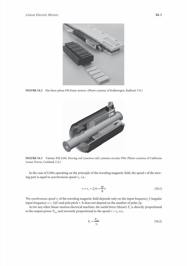
8102019 Power Handbook
httpslidepdfcomreaderfullpower-handbook 1843
34-3Linear Electric Motors
In the case o LSMs operating on the principle o the traveling magnetic 1047297eld the speed v o the mov-
ing part is equal to synchronous speed v s ie
v v s= = =2 τ ω
πτ
(341)
Te synchronous speed v s o the traveling magnetic 1047297eld depends only on the input requency (angular
input requency ω = 2π ) and pole pitch τ It does not depend on the number o poles 2 p
As or any other linear-motion electrical machine the useul orce (thrust) F x is directly proportional
to the output power P out and inversely proportional to the speed v = v s ie
F
P
v x
out
s
=
(342)
Flat three-phase PM linear motors (Photo courtesy o Kollmorgen Radord VA)
ubular PM LSM Moving rod (reaction rail) contains circular PMs (Photo courtesy o Caliornia
Linear Drives Carlsbad CA)
8102019 Power Handbook
httpslidepdfcomreaderfullpower-handbook 1943
34-4 Electric Power Generation Transmission and Distribution
Direct electromechanical drives with LSMs or actory automation systems can achieve speeds exceeding
600 mmin = 36 kmh and acceleration o up to 360 ms2 [7] Te thrust density ie thrust per active sur-
ace 2 pτLi where Li is the effective width o the stack
F
p Lx
x
i
=2
(Nm2
τ)
(343)
o LSMs is higher than that o LIMs (Figure 344)
Te polyphase (usually three-phase) armature winding can be distributed in slots made in the orm
o concentrated-parameter coils or made as a coreless (air-cored) winding layer PMs are the most popu-
lar 1047297eld excitation systems or short traveling distances (less than 10 m) or example actory transporta-
tion or automation systems A long PM rail would be expensive Electromagnetic excitation is used in
high-speed passenger transportation systems operating on the principle o magnetic levitation (maglev)
Te German system ransrapid uses vehicle-mounted steel core excitation electromagnets and station-
ary slotted armatures Japanese MLX001 test train sets use onboard superconducting (SC) air-cored
electromagnets and a stationary three-phase air-cored armature winding distributed along the guide-
way (Yamanashi Maglev est Line)
3412 Classi1047297cation
LSMs can be classi1047297ed according to whether they are
bull Flat (planar) or tubular (cylindrical)
bull Single sided or double sided
bull Slotted or slotless
0
10000
20000
30000
40000
50000
60000
0 2000 4000 6000 8000 10000 12000 14000
Trust N
T h r u s t d e n s i t y N m 2
LSM OC
LSM WC
LSM AC
LSM NC
LIM NC
Comparison o thrust density or single-sided LIMs and LSMs AC air cooling NC natural cool-
ing OC oil cooling WC water cooling (From Gieras JF Status o linear motors in the United States International
Symposium on Linear Drives or Industry Applications (LDIArsquo03) Birmingham UK pp 169ndash176 2003)
8102019 Power Handbook
httpslidepdfcomreaderfullpower-handbook 2043
34-5Linear Electric Motors
bull Iron cored or air cored
bull ransverse 1047298ux or longitudinal 1047298ux
Te topologies mentioned earlier are possible or nearly all types o excitation systems LSMs operating
on the principle o the traveling magnetic 1047297eld can have the ollowing excitation systems
bull PMs in the reaction railbull PMs in the armature (passive reaction rail)
bull Electromagnetic excitation system (with winding)
bull SC excitation system
bull Passive reaction rail with saliency and neither PMs nor windings (variable reluctance motors)
LSMs with electronically switched DC armature windings are designed either as linear stepping motors
or linear switched reluctance motors
34121 PM Motors with Active Reaction Rail
Figure 345a shows a single-sided 1047298at LSM with the armature winding located in slots and surace PMs
Figure 345b shows a similar motor with buried-type PMs In surace arrangement o PMs the yoke(back iron) o the reaction rail is erromagnetic and PMs are magnetized in the normal direction (per-
pendicular to the active surace) Buried PMs are magnetized in the direction o the traveling magnetic
1047297eld and the yoke is nonerromagnetic or example made o aluminum (Al) Otherwise the bottom
leakage 1047298ux would be greater than the linkage 1047298ux as shown in Figure 346 Te same effect occurs in
buried-type PM rotors o rotary machines in which the shaf must also be nonerromagnetic [239]
Te so-called Halbach array o PMs also does not require any erromagnetic yoke and excites stronger
magnetic 1047298ux density and closer to the sinusoids than a conventional PM array Te key concept o the
Halbach array is that the magnetization vector should rotate as a unction o distance along the array
(Figure 347)
It is recommended that a PM LSM be urnished with a damper A rotary synchronous motor has a cage
damper winding embedded in pole shoe slots When the speed is different rom the synchronous speed
electric currents are induced in damper circuits Te action o the armature magnetic 1047297eld and damper
currents allows or asynchronous starting damps the oscillations and helps to return to synchronous
operation when the speed decreases or increases Also a damper circuit reduces the backward-traveling
magnetic 1047297eld It would be rather difficult to urnish PMs with a cage winding so that the damper o PM
LSMs has the orm o an Al cover (Figure 348a) or solid steel pole shoes (Figure 348b) In addition steel
pole shoes or Al cover (shield) can protect brittle PMs against mechanical damage
Te detent orce ie attractive orce between PMs and the armature erromagnetic teeth orce ripple
and some higher-space harmonics can be reduced with the aid o skewed assembly o PMs Skewed PMs
can be arranged in one row (Figure 349a) two rows (Figure 349b) or even more rows
1 3
(a) (b)
N
S
τ τ
S
N
1 2 3
N S
τ τ
S N
Single-sided 1047298at PM LSMs with slotted armature core and (a) surace PMs and (b) buried PMs
1 PM 2 mild steel pole 3 yoke
8102019 Power Handbook
httpslidepdfcomreaderfullpower-handbook 2143
34-6 Electric Power Generation Transmission and Distribution
(a)
(b)
Magnetic 1047298ux distribution in the longitudinal sections o buried-type PM LSMs (a) nonerromag-
netic yoke and (b) erromagnetic yoke (back iron)
1
2
Double-sided LSM with Halbach array o PMs 1 PMs 2 coreless armature winding
2
2
3(a)
(b)
3
1
1
Dampers o surace-type PM LSMs (a) Al cover (shield) and (b) solid steel pole shoes 1 PM
2 damper 3 yoke
8102019 Power Handbook
httpslidepdfcomreaderfullpower-handbook 2243
34-7Linear Electric Motors
Speci1047297cation data o 1047298at single-sided PM LBMs manuactured by Anorad are shown in able 341 [1]
and motors manuactured by Kollmorgen are shown in able 342 [11] Te temperature 25degC 125degC
or 130degC or the thrust current resistance and power loss is the temperature o the armature winding
Te electromotive orce (EMF) constant kE in ables 341 and 342 or sinusoidal operation is de1047297ned
according to the equation expressing the EMF (induced voltage) excited by PMs without the armature
reaction ie
E k v E s=
(344)
where v s is the synchronous speed according to Equation 341 Tus the armature constant kE multiplied
by the synchronous speed v s gives the EMF E
S SN N N N N N
N N N N N N
N N N N N N
S S S S
S S S S S S
S
(b)
(a)
S S S S S
Skewed PMs in 1047298at LSMs (a) one row and (b) two rows
Flat Tree-Phase Single-Sided PM LBMs with Natural Cooling Systems
Manuactured by Anorad Hauppauge NY
Parameter LCD--1 LCD--2-P LCD--3-P LCD--4-P
Continuous thrust at 25degC N 163 245 327 490
Continuous current at 25degC A 42 63 85 127
Continuous thrust at 125degC N 139 208 277 416
Continuous current at 125degC A 36 54 72 108
Peak thrust (025 s) N 303 455 606 909
Peak current (025 s) A 92 138 184 276
Peak orce (10 s) N 248 373 497 745
Peak current (10 s) A 73 110 147 220Continuous power losses at 125degC W 58 87 115 173
Armature constant kE Vsm 129
Trust constant (three phases) kF NA 386
Resistance per phase at 25degC Ω 32 22 16 11
Inductance mH 143 95 71 48
PM pole pitch mm 2345
Maximum winding temperature degC 125
Armature assembly mass kg 18 24 36 48
PM assembly mass kgm 64
Normal attractive orce N 1036 1555 2073 3109
8102019 Power Handbook
httpslidepdfcomreaderfullpower-handbook 2343
34-8 Electric Power Generation Transmission and Distribution
Te thrust constant kF in ables 341 and 342 is de1047297ned according to the simpli1047297ed equation or the
developed electromagnetic thrust ie
F k I dx F a= cos Ψ
(345)
or a sinusoidally excited LSM with equal reluctances in the d - and q-axes and or the angle between the
armature current I a and the q-axis Ψ = 0deg (cos Ψ = 1) Tus the thrust constant kF times the armature
current I a gives the electromagnetic thrust developed by the LSM
Double-sided 1047298at PM LSMs consist o two external armature systems and one internal excitation sys-
tem (Figure 3410a) or one internal armature system and two external excitation systems (Figure 3410b)
In the second case a linear Grammersquos armature winding can be used
In slotless motors the primary winding is uniormly distributed on a smooth armature core or does
not have any armature core Slotless PM LSMs are detent orcendashree motors provide lower torque ripple
and at high input requency can achieve higher efficiency than slotted LSMs On the other hand larger
nonerromagnetic air gap requires more PM material and the thrust density (thrust per mass or volume)
is lower than that o slotted motors (able 343) Te input current is higher as synchronous reactances
Flat Tree-Phase Single-Sided PM LBMs with Natural Cooling Systems
Manuactured by Kollmorgen Radord VA
Parameter IC11-030 IC11-050 IC11-100 IC11-200
Continuous thrust at 130degC N 150 275 600 1260
Continuous current at 130degC A 40 44 48 50
Peak thrust N 300 500 1000 2000
Peak current A 79 79 79 79
Continuous power losses at 130degC W 64 106 210 418
Armature constant at 25degC kE Vsm 309 514 1028 2057
Trust constant (three phases) at 25degC kF NA 378 629 1259 2519
Resistance line to line at 25degC Ω 19 26 44 80
Inductance line to line mH 173 278 541 1066
Electrical time constant ms 89 105 123 134
Termal resistance winding to external
structure degCW
164 099 050 025
Maximum winding temperature degC 130
Armature assembly mass kg 20 32 62 122PM assembly mass kgm 55 76 128 269
Normal attractive orce N 1440 2430 4900 9850
(a)
N S N SN S N S
N S N SN S N S
(b)
Double-sided 1047298at PM LSMs with (a) two external armature systems and (b) one internal armature
system
8102019 Power Handbook
httpslidepdfcomreaderfullpower-handbook 2443
34-9Linear Electric Motors
in the d - and q-axes can decrease to a low undesired value due to the absence o teeth Figure 3411a
shows a single-sided 1047298at slotless motor with armature core and Figure 3411b shows a double-sided slot-
less motor with inner air-cored armature winding (moving coil motor)
able 344 contains perormance speci1047297cations o double-sided PM LBMs with inner three-phase air-
cored armature winding manuactured by rilogy Systems Corporation Webster X (Figure 3412)
N
(a) (b)
S N S N S N S
S N NS
Flat slotless PM LSMs (a) single-sided with armature core and (b) double-sided with inner air-
cored armature winding
Slotted versus Slotless LSMs
Quantity Slotted LSM Slotless LSM
Higher thrust density X
Higher efficiency in the lower speed range X
Higher efficiency in the higher speed range x
Lower input current X
Less PM material X
Lower winding cost x
Lower thrust pulsations x
Lower acoustic noise x
Flat Double-Sided PM LBMs with Inner Tree-Phase Air-Cored Series-Coil
Armature Winding Manuactured by rilogy Systems Corporation Webster X
Parameter 310-2 310-4 310-6
Continuous thrust N 1112 2091 3149
Continuous power or sinusoidal operation W 87 152 230
Peak thrust N 356 712 1068
Peak power W 900 1800 2700
Peakcontinuous current A 10028 10026 10026
Trust constant kF or sinusoidal operation NA 400 800 1200
Trust constant kF or trapezoidal operation with Hallsensors NA
351 725 1095
Resistance per phase Ω 86 172 258
Inductance plusmn05 mH 60 120 180
Heat dissipation constant or natural cooling WdegC 110 201 301
Heat dissipation constant or orced air cooling WdegC 130 240 355
Heat dissipation constant or liquid cooling WdegC 154 285 421
Number o poles 2 4 6
Coil length mm 1422 2642 3861
Coil mass kg 055 103 153
Mass o PM excitation systems kgm 1267 or 838
8102019 Power Handbook
httpslidepdfcomreaderfullpower-handbook 2543
34-10 Electric Power Generation Transmission and Distribution
By rolling a lat LSM around the axis parallel to the direction o the traveling magnetic ield
ie parallel to the direction o thrust a tubular (cylindrical) LSM can be obtained (Figure 3413) A
tubular PM LSM can also be designed as a double-sided motor or slotless motor
ubular single-sided LSMs LinMoreg with movable internal PM excitation system (slider) and stationaryexternal armature are manuactured by Sulzer Electronics AG Zurich Switzerland (able 345) All active
motor parts bearings position sensors and electronics have been integrated into a rigid metal cylinder [14]
LinMotreg is a registered trademark o Sulzer Electronics AG Zuumlrich Switzerland
(b)(a)
N S N S N S
N S N S N S
N S N S
SNN S
Single-sided slotted tubular PM LSMs (a) with external armature system and (b) with external
excitation system
Data o ubular LSMs LinMotreg Manuactured by Sulzer Electronics AG Zuumlrich Switzerland
Parameter P01 23 times 80 P01 23 times 160 P01 37 times 120 P01 37 times 240
Number o phases 2
PMs NdFeB
Maximum stroke m 0210 0340 1400 1460Maximum orce N 33 60 122 204
Maximum acceleration ms2 280 350 247 268
Maximum speed ms 24 42 40 31
Stator (armature) length m 0177 0257 0227 0347
Stator outer diameter mm 23 23 37 37
Stator mass kg 0265 0450 0740 1385
Slider diameter mm 12 12 20 20
Maximum temperature o the armature winding degC 90
Flat double-sided PM LSM with inner moving coil (Photo courtesy o rilogy Systems Webster X)
8102019 Power Handbook
httpslidepdfcomreaderfullpower-handbook 2643
34-11Linear Electric Motors
All the aorementioned PM LSMs are motors with longitudinal magnetic 1047298ux the lines o which lie
in the plane parallel to the direction o the traveling magnetic 1047297eld LSMs can also be designed as trans-
verse magnetic 1047298ux motors in which the lines o magnetic 1047298ux are perpendicular to the direction o the
traveling 1047297eld Figure 3414a shows a single-sided transverse 1047298ux LSM in which PMs are arranged in two
rows A pair o parallel PMs creates a two pole 1047298ux excitation system A double-sided con1047297guration o
transverse 1047298ux motor is possible however it is complicated and expensive (Figure 3414b)
34122 PM Motors with Passive Reaction Rail
Te drawback o PM LSMs is the large amount o PM material that must be used to design the excitation
system Normally expensive rare-earth PMs are requested I a small PM LSM uses say 10 kg o NdFeB
per 1 m o the reaction rail and 1 kg o good-quality NdFeB costs US$ 130 the cost o the reaction rail
without assembly amounts to US$ 1300 per 1 m Tis price cannot be acceptable or example in pas-
senger transportation systems
A cheaper solution is to apply the PM excitation system to the short armature that magnetizes the
long reaction rail and creates magnetic poles in it Such a linear motor is called the homopolar LSM
Te homopolar LSM as described in [517] is a double-sided AC linear motor that consists o two
polyphase armature systems connected mechanically and magnetically by a erromagnetic U-type yoke
(Figure 3415) Each armature consists o a typical slotted linear motor stack with polyphase armature
winding and PMs located between the stack and U-type yoke Since the armature and excitation systems
are combined together the armature stack is oversized as compared with a conventional steel-cored LSM
Te PMs can also be replaced by electromagnets [1719] Te variable reluctance reaction rail is passive
Te saliency is created by using erromagnetic (solid or laminated) cubes separated by a nonerromag-netic material Te reaction rail poles are magnetized by the armature PMs through the air gap Te trav-
eling magnetic 1047297eld o the polyphase armature winding and salient poles o the reaction rail produce the
thrust Such a homopolar LSM has been proposed or the propulsion o maglev trains o Swissmetro [17]
Further simpli1047297cation o the double-sided con1047297guration can be made to obtain a single-sided PM
LSM shown in Figure 3416
3413 Flux-Switching PM Linear Motors
Large gantry systems and machining centers require powerul linear motors preerably with PM-ree
reaction rail Siemens 1FN6 PM LSMs with a magnet-ree reaction rail belong to the group o the so
5
(a) (b)
5
N S
N
N
3
4
4
3
2
6
1
3
6
1
6
1
i
S
2
2
N
N
SNN
S
ransverse 1047298ux PM LSM (a) single-sided and (b) double-sided 1 armature winding 2 armature
laminated core 3 PM 4 back erromagnetic core 5 magnetic 1047298ux 6 armature current
8102019 Power Handbook
httpslidepdfcomreaderfullpower-handbook 2743
34-12 Electric Power Generation Transmission and Distribution
called 1047298ux-switching PM machines [1016] Te armature system is air cooled degree o protection IP23
class o insulation F line voltage rom 400 to 480 V rated thrust rom 235 to 2110 N maximum veloc-
ity at rated thrust rom 170 to 540 mmin (able 346) overload capacity 38 o rated thrust modular
type construction [20] Tese LSMs operate with Siemens Sinamics or Simodrive solid-state converters
and external encoders According to Siemens [20] these new LSMs produce thrust orces and velocities
equivalent to competitive classical models or light-duty machine tool machine accessory and material
handling applications
2 3 244 1
N
S
S
N
N
S
S
N
5
Single-sided PM LSM with a passive reaction rail 1 PM 2 armature winding 3 armature stack
4 yoke 5 erromagnetic reaction rail
1
1
2 343
5
Fe Fe Fe Fe
Double-sided homopolar PM LSM with passive reaction rail 1 PM 2 armature winding
3 armature stack 4 yoke 5 reaction rail
Speci1047297cations o 1FN6 PM LSMs Manuactured by Siemens Erlangen Germany
Armature Unit Rated Trust N Max Trust N
Max Speed at
Rated Trust
mmin
Max Speed at
Max Trust
mmin
Rated
Current A Max Current A
1FN6008-1LC17 235ndash350 900 263 103 17ndash26 90
1FN6008-1LC37 235ndash350 900 541 224 35ndash53 180
1FN6016-1LC30 470ndash710 1800 419 176 54ndash80 280
1FN6016-1LC17 935ndash1400 3590 263 101 70ndash105 360
1FN6024-1LC12 705ndash1060 2690 176 69 35ndash53 180
1FN6024-1LC20 705ndash1060 2690 277 114 54ndash80 280
1FN6024-1LG10 2110ndash3170 8080 172 62 105ndash160 540
1FN6024-1LG17 2110ndash3170 8080 270 102 162ndash243 840
Source Synchronous Linear Motor 1FN6 Te Electrical Gear Rack Siemens AG Industry Sector Drive echnologies
Motion Control Erlangen Germany 2008
8102019 Power Handbook
httpslidepdfcomreaderfullpower-handbook 2843
34-13Linear Electric Motors
Te magnet-ree reaction rail is easy to install and does not require the saety considerations o stan-
dard PM reaction rails Without PMs there is no problem with errous chips and other debris beingattracted to these sections Maintenance becomes a simple matter o installing a wiper or brush on the
moving part o the slide
Te 1047298ux-switching LSM comprises an armature section that is equipped with coils and PMs as well
as a nonmagnetic toothed reaction rail section (Figure 3417) Te key design innovation is an LSM in
which PMs are integrated directly into the lamination o the armature core along with the individual
windings or each phase Both magnitudes and polarities o the linkage 1047298ux in the armature winding
vary periodically along with the reaction rail movement Te magnetic 1047298ux between the armature core
and steel reaction rail is controlled by switching the three-phase armature currents according to a desig-
nated algorithm Te passive reaction rail consists o milled steel with poles (teeth) and is much simpler
to manuacture
3414 Motors with Electromagnetic Excitation
Te electromagnetic excitation system o an LSM is similar to the salient-pole rotor o a rotary
synchronous motor Figure 3418 shows a 1047298at single-sided LSM with salient erromagnetic poles and
DC 1047297eld excitation winding Te poles and pole shoes can be made o solid steel laminated steel or sin-
tered powder I the electromagnetic excitation system is integrated with the moving part the DC cur-
rent can be delivered with the aid o brushes and contact bars inductive power transer (IP) systems
linear transormers or linear brushless exciters
A AB BC C
1
2
3
4
5
v
τ2
τ1
Construction o 1047298ux-switching LSM with PM-ree reaction rail 1 laminated armature core
2 PM 3 armature coil (phase C) 4 toothed passive steel reaction rail 5 linkage magnetic 1047298ux (phase A is on)
1
3
τ τ
2
S
d d q q q
4
N
Electromagnetic excitation system o a 1047298at single-sided iron-cored LSM 1 salient pole 2 DC
excitation winding 3 erromagnetic rail (yoke) 4 armature system
8102019 Power Handbook
httpslidepdfcomreaderfullpower-handbook 2943
34-14 Electric Power Generation Transmission and Distribution
LSMs with electromagnetic excitation (wound-1047297eld reaction rail) are used in German ransrapid
maglev train (Figure 3419)
3415 Motors with Superconducting Excitation System
In large-power LSMs the electromagnets with erromagnetic core that produce the excitation 1047298ux can
be replaced by coreless SC electromagnets Since the magnetic 1047298ux density produced by the SC electro-
magnet is greater than the saturation magnetic 1047298ux density o the best laminated alloys ( Bsat asymp 24 or
cobalt alloy) there is no need to use the armature erromagnetic core An LSM with SC 1047297eld excitation
system is a totally air-cored machine (Figure 3420)
Experimental maglev trains on the Yamanashi Maglev est Line (YML) in Yamanashi Preecture(west rom okyo) Japan are driven by air-cored LSMs with SC excitation systems ( Figure 3421)
342 Linear Induction Motors
LIMs have ound the widest prospects or applications in transportation systems beginning with electri-
cal traction on small passenger or material supply cars (used at airports exhibitions electrohighways
elevators) and ending with pallet transportation waer transportation belt conveyors transportation
systems o bulk materials etc Te second important place or LIM applications is in industry ie man-
uacturing processes (machine tools hammers presses mills separators automated manuacturing systems
strip tensioners textile shuttles index tables turntables disk saws or wood sliding doors robots etc)
ransrapid 09 maglev train driven by LSMs with electromagnetic excitation (Photo courtesy oTyssen ransrapid System GmbH Munich Germany)
1
2A
B
C B
A
A
C
S SN
τ τ τ τ τ
N N
CBA
Tree-phase air-cored LSM with SC excitation system 1 armature coils 2 SC excitation coils
8102019 Power Handbook
httpslidepdfcomreaderfullpower-handbook 3043
34-15Linear Electric Motors
LIMs can also play an important part in industrial investigations and tests or example high acceleration
o model aircraf in aerodynamic tunnels high acceleration o vessels in laboratory pools propulsion o
mixers shakers and vibrators and adjusting xndashy tables and instruments Tere is also a possibility o
using LIMs in consumer electronics (sound and vision equipment knitting machines curtains) and in
offices (transportation o documents letters and cash) Te Handbook o Linear Motor Applications [21]
printed in Japan in 1986 contains about 50 examples o applications o LIMs in operation or in the pro-
cess o implementation
3421 Basic Geometries and Constructions
A LIM can be obtained by cutting in the same way either a cage rotor induction motor or a wound rotor
induction motor Te stator becomes the primary and the rotor becomes the secondary [12] Te secondary
o a LIM can be simpli1047297ed by using a solid steel core and replacing the cage (ladder) or slip-ring winding with
a high-conductivity nonerromagnetic plate (Al or Cu) Te nonerromagnetic plate is a secondary electric
circuit with distributed parameters and the erromagnetic core is a conductor both or the magnetic 1047298ux
and the electric current It does not matter rom the principle o operation point o view which part (primary
or secondary) is in motion Tus the 1047298at single-sided LIM can be obtained rom a solid rotor induction
motor (Figure 341a) and the 1047298at double-sided LIM can be obtained rom a hollow-rotor induction motor
with wound external and internal stator (Figure 341b) In a double-sided LIM the secondary erromagneticcore is not necessary since the magnetic 1047298ux excited by one o the primary windings afer passing through
the air gaps and nonerromagnetic secondary is then closed up by the core o the second primary unit
Teoretically a double-sided LIM with primary windings located on two cores in comparison with a
single-sided LIM exciting the same MMF has twice the air gap magnetic 1047298ux density Tereore the thrust
o such a motor is our times greater assuming the same dimensions I only one primary core is wound
the output parameters o a double-sided LIM are the same as those or a single-sided LIM with laminated
secondary back iron Te undamental advantage o double-sided LIMs is the elimination o the normal
attractive orce between the primary and the secondary because the secondary is usually nonerromagnetic
Flat LIMs can have primary cores consisting o an array o cores arranged in parallel at appropri-
ate distances and connected magnetically by additional yokes perpendicular to the direction o the
YML in Yamanashi Preecture (near okyo) Japan YML maglev trains use air-cored LSMs
with SC excitation system (Photo courtesy o Central Japan Railway Company and Railway echnical Research
Institute okyo Japan)
8102019 Power Handbook
httpslidepdfcomreaderfullpower-handbook 3143
34-16 Electric Power Generation Transmission and Distribution
traveling 1047297eld A magnetic circuit designed in such a way makes it possible to apply two windings in
general multiphase windings with perpendicular conductors as shown in Figure 3422 Adjusting the
current in each winding the secondary can be moved in two perpendicular directions and can be posi-
tioned at any point o the xndashy plane A 1047298at LIM with two degrees o reedom (DOFs) can be designed both
as single-sided and double-sided machines
By rolling a 1047298at single-sided or double-sided LIM around the axis parallel to the direction o the travel-
ing magnetic 1047297eld ie parallel to the direction o the thrust a tubular motor can be obtained (Figure 3423)
A tubular (cylindrical) LIM similar to a 1047298at LIM can be designed both as single-sided and double-
sided machines and can have a square or rectangular cross section as in Figure 3424 Tere are possible
Te primary o a 1047298at LIM with two DOFs
g
g
g 1
g 2
(c)
(b)
(a)
d
v
v
v
1
1
1 1
1
1
2
2
2
2
2
2
ubular LIMs (a) single-sided with an external short primary (b) single-sided with an external
short secondary and (c) double-sided with short primary 1 primary 2 secondary
8102019 Power Handbook
httpslidepdfcomreaderfullpower-handbook 3243
34-17Linear Electric Motors
con1047297gurations other than that in Figure 3423 regarding the length o the secondary with respect to thelength o the primary
All the aorementioned LIMs are motors with longitudinal magnetic 1047298ux ie the lines o magnetic
1047298ux lie in the plane parallel to the direction o the traveling magnetic 1047297eld A LIM can also be designed
in such a way as to obtain magnetic 1047298ux lines perpendicular to the direction o the traveling 1047297eld Such
motors are said to have transverse magnetic 1047298ux (Figure 3425)
Te undamental advantage o a LIM with transverse magnetic 1047298ux in comparison with a LIM with
longitudinal magnetic 1047298ux is the lower magnetizing current necessary due to the shorter magnetic 1047298ux
paths Te signi1047297cant disadvantage is lower thrust A 1047298at LIM with transverse magnetic 1047298ux usually has
a primary winding o concentrated coils located on salient poles
A 1047298at single-sided LIM with transverse 1047298ux can produce not only thrust but also electrodynamic
suspension In the design shown in Figure 3426 the secondary is suspended electrodynamically andpropelled and stabilized laterally by the primary magnetic 1047297eld [8] Te primary magnetic circuit con-
sists o E-shaped laminations assembled in two rows Te short secondary is made o light Al alloy in the
orm o a boat Te lateral sides o the boat are inclined by 60deg with respect to the active surace Such a
shape provides maximum normal repulsive orce and maximum lateral stabilization
According to their geometry the LIMs can be divided into the ollowing groups
bull With movable primary or movable secondary
bull Single sided and double sided
bull Flat and tubular
bull With short primary and short secondary
bull With longitudinal and transverse magnetic 1047298ux
1 2 3 4 1 2 3 4
ubular double-sided LIM with a square cross section 1 primary 2 secondary 3 primary coil
4 internal core
v
v
1 1
1
1
(a)
(b)
22
22
Flat LIM with transverse magnetic 1047298ux and salient poles (a) single-sided and (b) double-sided
1 primary 2 secondary
8102019 Power Handbook
httpslidepdfcomreaderfullpower-handbook 3343
34-18 Electric Power Generation Transmission and Distribution
Te linear speed o a LIM is
v s v s= minus( )1 (346)
where
s is the slip
v s is the synchronous speed according to Equation 341
Neglecting the longitudinal end effect [6] the electromagnetic thrust developed by a LIM can be
expressed in a similar way as or a rotary induction motor ie
F
m
v I
R
sdx
s
= prime( ) prime1
2
2 2
(347)
where
m1 is the number o phases o the primary winding
v s is the synchronous speed according to Equation 341
primeI 2 is the secondary current reerred to the primary system
primeR2 is the secondary resistance reerred to the primary system
s is the slip
Te secondary resistance primeR2 must include the so-called edge effect [6]
3422 Propulsion of Wheel-on-Rail Vehicles
Modern railway systems and electrical traction should meet the ollowing requirements
bull High level o automatization and computerization
bull Propulsion and braking independent o adhesion which in turn is affected 1047297rst o all by climate
and weather
bull Low level o noise sometimes below 70 dB (A)
Flat LIM with transverse magnetic 1047298ux salient poles and nonerromagnetic secondary pro-
pelled suspended and stabilized electrodynamically (From Gieras JF et al Analytical calculation o electro-
dynamic levitation orces in a special-purpose linear induction motor International Electric Machines and Drives
Conerence (IEMDCrsquo11) Niagara Falls Ontario Canada 2011 [on CD-ROM])
8102019 Power Handbook
httpslidepdfcomreaderfullpower-handbook 3443
34-19Linear Electric Motors
bull Ability to cope with high slopes at least 6 and sharp bends with radius o curvature less than 20 m
bull No pollution to natural environment and landscape
bull High reliability
Te congestion problems o big cities should be solved by creating collective transport orms that can be
implemented without affecting a highly populated city For example there are many cities in Italy where
the historical center has remained the same since the Renaissance A heavy railway might be a com-
pletely wrong solution and have a notable impact on the city planning An adequate solution might be
a light railway a people mover with transport capacity o 10000ndash20000 passengers per hour to replace
the traditional transport nets and to integrate the existing railway nets
All the requirements mentioned earlier can be met by using LIMs as propulsion machines Replacing
electrical rotary motors with linear motors in traction drives (electrical locomotives) generally does
not require new tracks but only their adjustment to linear drives Single-sided LIMs (Figure 3427a and b)
are best since the normal attractive orce o these can strengthen the adhesion o wheels and rails
Te air gap is rom 10 to 15 mm Most requently the motor car has two LIMs with short primaries
(Figure 3427a) assembled in series Te double-layer secondary consists o a solid back iron and an Al
cap and is located between the rails Cables or computer communication with the vehicle and quite
ofen collectors or electrical energy delivery to the vehicle are located along the track Tree-phaseLIMs are ed rom variable-voltage variable-requency (VVVF) voltage-source inverters A linear pro-
pulsion system o wheel-on-rail vehicles allows more 1047298exibility (Figure 3428) reducing noise on bends
and wear o the wheels and rails
Double-sided LIMs (Figure 3427c and d) have ound very limited application due to the technical
difficulty o eliminating aults caused by bends in the secondary with primary cores on either side It is
more difficult to keep a small and uniorm air gap in double-sided LIMs than that in single-sided LIMs
Te LIM-driven wheel-on-rail vehicles are built or low velocities ie less than 100 kmh and or
short routes ie less than 50 km (urban transit systems and short-distance trains) At present LIM-
driven trains operate in oronto and Vancouver BC Canada in Detroit MI (Figure 3429) okyo
(Figure 3430) and Osaka Japan and Kuala Lumpur Malaysia
(a) (b)
(c) (d)
LIM-driven wheel-on-rail cars (a) single-sided LIM with short primary mounted on the undercar-
riage (b) single-sided LIM with short secondary mounted on the undercarriage (c) double-sided LIM with short pri-
mary mounted on the undercarriage and (d) double-sided LIM with short secondary mounted on the undercarriage
8102019 Power Handbook
httpslidepdfcomreaderfullpower-handbook 3543
34-20 Electric Power Generation Transmission and Distribution
(a) (b)
Te undercarriage o a wheel-on-rail vehicle (a) rotary motor propulsion and (b) LIM propulsion
Detroit people mover driven by single-sided LIMs
oei Oedo subway line in okyo driven by single-sided LIMs
8102019 Power Handbook
httpslidepdfcomreaderfullpower-handbook 3643
34-21Linear Electric Motors
Te design data o some single-sided traction LIMs are presented in able 347 and double-sided trac-
tion LIMs in able 348
343 Variable Reluctance Motors
Te simplest construction o a variable reluctance LSM or linear reluctance motor (LRM) is that shown
in Figure 3418 with DC excitation winding being removed However the thrust o such a motor wouldbe low as the ratio o d -axis permeance to q-axis permeance is low Better perormance can be obtained
when using 1047298ux barriers [18] or steel laminations [15] o make 1047298ux barriers any nonerromagnetic
materials can be used o obtain high permeance (low reluctance) in the d -axis and low permeance in
the q-axis steel laminations should be oriented in such a way as to create high permeance or the d -axis
magnetic 1047298ux
Figure 3431a shows a variable reluctance platen with 1047298ux barriers and Figure 3431b shows how to
arrange steel laminations to obtain different reluctances in the d - and q-axes Te platen can be com-
posed o segments the length o which is equal to the pole pitchτ Each segment consists o semicircular
lamellas cut out rom electrotechnical sheet A 1047297lling or example epoxy resin is used to make the seg-
ment rigid and robust By putting the segments together a platen o any desired length can be obtained
Design Data o Single-Sided Tree-Phase LIMs or Propulsion o Vehicles
Quantity
LIM
UnitJLMDR ICS KU CIGG GEC
Pullout thrust at requency given
in the ollowing F x
125 90 35 17 07 kN
Input requency 200 400 250 400 600 Hz
Rated phase current V 1 2750 4650 1300 2000 2000 A
Number o poles 2 p 8 6 4 6 4 mdash
Number o turns per phase N 1 128 96 128 108 48 mdash
Equivalent diameter o conductor d 1 mdash 893 528 1115 81 mm
Number o parallel conductors mdash 1 mdash 19 1 mdash
Effective width o primary core Li 023 0216 029 0101 01715 m
Pole pitch τ 027 02868 030 025 020 m
Length o single end connection l e mdash 03483 mdash 02955 03685 m
Coil pitch wc 0225 01673 025 01944 01555 m
Air gap g 150 126 120 150 182 mm
Number o slots z 1( primez 1) 96(106) 72(79) 48(58) 54(61) 36(43) mdash
Width o slot b11 mdash 156 170 150 1308 mm
Width o slot opening b14 mdash 156 mdash 1044 1308 mm
Depth o slot h11 mdash 530 380 3421 6147 mm
Height o yoke h1 y mdash 436 393 7163 500 mm
Conductivity o back iron at 20degC σFe mdash 446 952 446 512 times106 Sm
Conductivity o Al cap at 20degC σ Al mdash 300 303 323 215 times106 Sm
Width o back iron w 03 024 03 0111 01715 m
Tickness o back iron hsec 190 125 250 254 474 mm
Tickness o Al cap d 50 45 50 45(25) 32 mm
Tickness o Al cap behind Fe core t ov 50 170 50 127 32 mm
Width o Al cap 030 032 040 0201 02985 m
JLMDR Japanese Linear Motor Driven Railcar Japan ICS Intermediate Capacity ransit System Canada KU
Kyushu University LIM Japan CIGG Canadian Inst o Guided Ground ransport Canada GEC General
Electric Company United States (z 1 ) is the number o hal 1047297lled slots
8102019 Power Handbook
httpslidepdfcomreaderfullpower-handbook 3743
34-22 Electric Power Generation Transmission and Distribution
344 Stepping Motors
A linear stepping motor has a concentrated armature winding wound on salient poles and PM excitation
rail or variable reluctance platen Te thrust is generated as an action o the armature magnetic 1047298ux and
PM 1047298ux (active platen) or the armature magnetic 1047298ux and salient erromagnetic poles (variable reluc-
tance platen) Stepping motors have no position eedback
Design Data o Double-Sided Tree-Phase LIMs or Propulsion
o Vehicles
Quantity
LIM
UnitGEC LIMVR
Maximum thrust at input requency F x given in the ollowing 085 1668 kN
Input requency 600 1730 Hz
Input phase current I 1 2000 20000 A
Number o poles 2 p 4 10 mdash
Number o turns per phase N 1 144 100 mdash
Diameter o conductor d 1 075 110 mm
Effective width o primary core Li 00869 0254 m
Pole pitch τ 01795 03556 m
Coil pitch wc 005 005 m
Number o slots z 1( primez 1) 36(45) 150(160) mdash
Width o slot b11 137 160 mm
Width o slot opening b14 137 mdash mm
Depth o slot h1 630 mdash mm
Height o yoke h1 y 239 mdash mm
Width o tooth c1 200 77 mm
Resultant air gap 2 g + d 381 38075 mm
Air gap g 2 times 127 2 times 111 mm
Tickness o secondary d 127 15875(hollow) mm
Effective thickness o Al secondary 127 72 mm
Width o secondary w ge03046 mdash m
Conductivity o Al cap at 20degC σ Al asymp2434 asymp240 times106 Sm
GEC General Electric Company United States LIMVR LIM Research Vehicle
Pueblo CO United States (z 1 ) is the number o hal 1047297lled slots
(a) (b)
q q d d d q d q d d
Laminations
τ τ τ τ
Epoxy resin
Variable reluctance LSMs with (a) 1047298ux barriers and (b) steel laminations
8102019 Power Handbook
httpslidepdfcomreaderfullpower-handbook 3843
8102019 Power Handbook
httpslidepdfcomreaderfullpower-handbook 3943
34-24 Electric Power Generation Transmission and Distribution
Tis value is different or ull-step and microstepping drives Te maximum startndashstop speed is the
maximum speed that can be used when starting or stopping the motor without ramping that does not
cause the motor to all out o synchronism or lose steps Te maximum speed is the maximum linear
speed that can be achieved without the motor stalling or alling out o synchronism Te maximum
load mass is the maximum allowable mass applied to the orcer against the scale that does not result in
mechanical damage Te ull-step resolution is the position increment obtained when the currents are
switched rom one winding to the next winding Tis is the typical resolution obtained with ul l-step
drives and it is strictly a unction o the motor construction Te microstepping resolution is the position
increment obtained when the ull-step resolution is divided electronically by proportioning the currents
in the two windings Tis resolution is typically 10ndash250 times smaller than the ull-step resolution [13]
HLSMs are regarded as an excellent solution to positioning systems that require a high accuracy
and rapid acceleration With a microprocessor controlled microstepping mode a smooth operation with
standard resolution o a ew hundred stepsmm can be obtained Te advantages such as high efficiencyhigh throughput mechanical simplicity high reliability precise open-loop operation and low inertia
o the system have made these kind o motors more and more attractive in such applications as actory
automation high speed positioning computer peripherals acsimile machines numerically controlled
machine tools automated medical equipment automated laboratory equipment and welding robots
Tis motor is especially suitable or machine tools printers plotters and computer-controlled material
handling in which a high positioning accuracy and repeatability are the key problems
When two or our orcers mounted at 90deg and a special grooved platen (ldquowaffle platerdquo) are used the
xndashy motion (two DOFs) in a single plane is obtained (Figure 3434)
Speci1047297cation data o the xndashy HLSMs manuactured by Normag Northern Magnetics Inc Santa
Clarita CA are given in able 3410
PM linear stepping motors (Photo courtesy o okyo Aircraf Instrument Co Ltd okyo Japan)
8102019 Power Handbook
httpslidepdfcomreaderfullpower-handbook 4043
34-25Linear Electric Motors
345 Switched Reluctance Motors
Te topology o a linear switched reluctance motor is similar to that o a stepping motor with variable
reluctance platen In addition it is equipped with position sensors Te turn-on and turn-off instant o
the input current is synchronized with the position o the moving part Te thrust is very sensitive to
the turn-on and turn-off instant
In the case o a linear stepping or linear switched reluctance motor the speed v o the moving part is
v v s sw= = τ
(348)
where
sw is the undamental switching requency in one armature phase winding
τ is the pole pitch o the reaction rail
For a rotary stepping or switched reluctance motor sw = 2 pr n where 2 pr is the number o rotor poles and
n is rotational speed in revs
A linear switched reluctance motor has a doubly salient magnetic circuit with a polyphase winding
on the armature Longitudinal and transverse 1047298ux designs are shown in Figure 3435 A linear switched
reluctance motor allows precise speed and position-controlled linear motion at low speeds and is not sub-
ject to design constraints (minimum speed limited by minimum easible pole pitch) o linear AC motors
x
y
12
3
4
1
1
2
2
HLSM with a our-unit orcer to obtain the xndashy motion 1 orcers or the x -direction 2 orcers
or the y -direction 3 platen 4 air pressure
Data o xndashy HLSMs Manuactured by Normag Northern Magnetics Inc
Santa Clarita CA
Parameter 4XY0602-2-0 4XY2002-2-0 4XY2004-2-0 4XY2504-2-0
Number o orcer units per axis 1 1 2 2
Number o phases 2 2 2(4) 2(4)Static thrust N 133 400 980 1330
Trust at 1 ms N 111 311 712 980
Normal attractive orce N 1600 4000 14400 18000
Resistance per phase Ω 29 33 16 19
Inductance per phase mH 15 40 20 23
Input phase current A 20 20 40 40
Air gap mm 002
Maximum temperature degC 110
Mass kg 32 072 20 15
Repeatability mm 000254
Resolution mm 000254
Bearing type Air
8102019 Power Handbook
httpslidepdfcomreaderfullpower-handbook 4143
34-26 Electric Power Generation Transmission and Distribution
346 Linear Positioning Stages
Linear motors are now playing a key role in advanced precision linear positioning Linear precision posi-
tioning systems can be classi1047297ed into open-loop systems with HLSMs and closed-loop servo systems
with LSMs LBMs or LIMs
A PM LSMndashdriven positioning stage is shown in Figure 3436 A stationary base is made o Al steel
ceramic or granite plate It provides a stable precise and 1047298at platorm to which all stationary position-
ing components are attached Te base o the stage is attached to the host system with the aid o mount-
ing screws
Te moving table accommodates all moving positioning components o achieve maximum accelera-
tion the mass o the moving table should be as small as possible and usually Al is used as a lightweight
material A number o mounting holes on the moving table is necessary to 1047297x the payload to the mount-
ing table
Linear bearing rails provide a precise guidance to the moving table A minimum o one bearing rail
is required Linear ball bearing or air bearings are attached to each rail
Te armature o a linear motor is astened to the moving table and reaction rail (PM excitation sys-tem) is built in the base between the rails (Figure 3436)
A linear encoder is needed to obtain precise control o position o the table velocity and acceleration
Te read head o the encoder is attached to the moving table
(a) (b)
3
3
221
1
Linear switched reluctance motor con1047297gurations (a) longitudinal 1047298ux design and (b) transverse
1047298ux design 1 armature winding 2 armature stack 3 platen
12
3
5
4
7
6
8
Linear positioning stage driven by PM LBM 1 base 2 moving table 3 armature o LBM 4 PMs
5 linear bearing 6 encoder 7 cable carrier 8 limit switch (Courtesy o Normag Santa Clarita CA)
8102019 Power Handbook
httpslidepdfcomreaderfullpower-handbook 4243
34-27Linear Electric Motors
Noncontact limit switches ixed to the base provide an overtravel protection and init ial homing
A cable carrier accommodates and routes electrical cables between the moving table and stationary
connector box 1047297xed to the base
An HLSM-driven linear precision stage is o similar construction Instead o PMs between bearing
rails it has a variable reluctance platen HLSMs usually need air bearings and in addition to the electri-
cal cables an air hose between air bearings and the compressor is requiredLinear positioning stages are used in semiconductor technology electronic assembly quality assur-
ance laser cutting optical scanning water jet cutting gantry systems (x y z stages) color printers
plotters and Cartesian coordinate robotics
References
1 Anorad Linear Motors Inormation Brochure Anorad Hauppauge New York 2007 wwwanoradcom
2 Boldea I and Nasar SA Linear Motion Electromagnetic Systems John Wiley amp Sons New York 1985
3 Boldea I and Nasar SA Linear Electric Actuators and Generators Cambridge University Press
New York 2005
4 Compumotor Digiplan Positioning Control Systems and Drives Parker Hanni1047297n CorporationRohnert Park CA 2011
5 Everes W Henneberger G Wunderlich H and Selig A A linear homopolar motor or a trans-
portation system 2nd International Symposium on Linear Drives or Industry Applications (LDIArsquo98)
okyo Japan 1998 pp 46ndash49
6 Gieras JF Linear Induction Drives Clarendon Press Oxord UK 1994
7 Gieras JF Status o linear motors in the United States International Symposium on Linear Drives
or Industry Applications (LDIArsquo03) Birmingham UK 2003 pp 169ndash176
8 Gieras JF Gientkowski Z Mews J and Splawski P Analytical calculation o electrodynamic
levitation orces in a special-purpose linear induction motor International Electric Machines and
Drives Conerence (IEMDCrsquo11) Niagara Falls Ontario Canada 2011 [on CD-ROM]
9 Gieras JF Piech ZJ and omczuk BZ Linear Synchronous Motors ransportation and Automation Systems aylor amp Francis (CRC Press) Boca Raton FL 2011
10 Hoang E Ahmed AHB and Lucidarme J Switching 1047298ux permanent magnet polyphase syn-
chronous machines 7th European Conerence on Power Electronics and Applications (EPErsquo97)
Vol 3 rondheim Norway 1977 pp 903ndash908
11 Kollmorgen Linear Motors Aim to Cut Cost o Semiconductors and Electronics Manuacture
Kollmorgen Radord VA 1997
12 Laithwaite ER A History o Linear Electric Motors Macmillan London UK 1987
13 Linear Step Motor Inormation Brochure okyo Aircraf Instrument Co Ltd okyo Japan
1998
14 LinMot Design Manual Sulzer Electronics Ltd Zuumlrich Switzerland 1999
15 Locci N and Marongiu I Modelling and testing a new linear reluctance motor InternationalConerence on Electrical Machines (ICEMrsquo92) Vol 2 Manchester UK 1992 pp 706ndash710
16 Rauch SE and Johnson LJ Design principles o 1047298ux-switch alternators AIEE rans Part III
74(12) 1261ndash1269 1955
17 Rosenmayr M Casat Glavitsch A and Stemmler H SwissmetromdashPower supply or a high-
power-propulsion system with short stator linear motors 15th International Conerence on
Magnetically Levitated Systems and Linear Drives Maglevrsquo98 Mount Fuji Yamanashi Japan 1998
pp 280ndash286
18 Sanada M Morimoto S and akeda Y Reluctance equalization design o multi 1047298ux barrier con-
struction or linear synchronous reluctance motors 2nd International Symposium on Linear Drives
or Industrial Applications (LDIArsquo98) okyo Japan 1998 pp 259ndash262
8102019 Power Handbook
httpslidepdfcomreaderfullpower-handbook 4343
34-28 Electric Power Generation Transmission and Distribution
19 Seok-Myeong J and Sang-Sub J Design and analysis o the linear homopolar synchronous motor
or integrated magnetic propulsion and suspension 2nd International Symposium on Linear Drives
or Industrial Applications (LDIArsquo98) okyo Japan 1998 pp 74ndash77
20 Synchronous Linear Motor 1FN6 Te Electrical Gear Rack Siemens AG Industry Sector Drive
echnologies Motion Control Erlangen Germany 2008
21 Yamada H Handbook o Linear Motor Applications (in Japanese) Kogyo Chosaki Publishing Cookyo Japan 1986
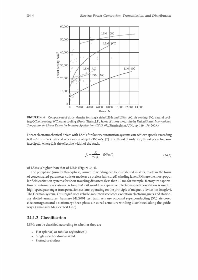
8102019 Power Handbook
httpslidepdfcomreaderfullpower-handbook 1943
34-4 Electric Power Generation Transmission and Distribution
Direct electromechanical drives with LSMs or actory automation systems can achieve speeds exceeding
600 mmin = 36 kmh and acceleration o up to 360 ms2 [7] Te thrust density ie thrust per active sur-
ace 2 pτLi where Li is the effective width o the stack
F
p Lx
x
i
=2
(Nm2
τ)
(343)
o LSMs is higher than that o LIMs (Figure 344)
Te polyphase (usually three-phase) armature winding can be distributed in slots made in the orm
o concentrated-parameter coils or made as a coreless (air-cored) winding layer PMs are the most popu-
lar 1047297eld excitation systems or short traveling distances (less than 10 m) or example actory transporta-
tion or automation systems A long PM rail would be expensive Electromagnetic excitation is used in
high-speed passenger transportation systems operating on the principle o magnetic levitation (maglev)
Te German system ransrapid uses vehicle-mounted steel core excitation electromagnets and station-
ary slotted armatures Japanese MLX001 test train sets use onboard superconducting (SC) air-cored
electromagnets and a stationary three-phase air-cored armature winding distributed along the guide-
way (Yamanashi Maglev est Line)
3412 Classi1047297cation
LSMs can be classi1047297ed according to whether they are
bull Flat (planar) or tubular (cylindrical)
bull Single sided or double sided
bull Slotted or slotless
0
10000
20000
30000
40000
50000
60000
0 2000 4000 6000 8000 10000 12000 14000
Trust N
T h r u s t d e n s i t y N m 2
LSM OC
LSM WC
LSM AC
LSM NC
LIM NC
Comparison o thrust density or single-sided LIMs and LSMs AC air cooling NC natural cool-
ing OC oil cooling WC water cooling (From Gieras JF Status o linear motors in the United States International
Symposium on Linear Drives or Industry Applications (LDIArsquo03) Birmingham UK pp 169ndash176 2003)
8102019 Power Handbook
httpslidepdfcomreaderfullpower-handbook 2043
34-5Linear Electric Motors
bull Iron cored or air cored
bull ransverse 1047298ux or longitudinal 1047298ux
Te topologies mentioned earlier are possible or nearly all types o excitation systems LSMs operating
on the principle o the traveling magnetic 1047297eld can have the ollowing excitation systems
bull PMs in the reaction railbull PMs in the armature (passive reaction rail)
bull Electromagnetic excitation system (with winding)
bull SC excitation system
bull Passive reaction rail with saliency and neither PMs nor windings (variable reluctance motors)
LSMs with electronically switched DC armature windings are designed either as linear stepping motors
or linear switched reluctance motors
34121 PM Motors with Active Reaction Rail
Figure 345a shows a single-sided 1047298at LSM with the armature winding located in slots and surace PMs
Figure 345b shows a similar motor with buried-type PMs In surace arrangement o PMs the yoke(back iron) o the reaction rail is erromagnetic and PMs are magnetized in the normal direction (per-
pendicular to the active surace) Buried PMs are magnetized in the direction o the traveling magnetic
1047297eld and the yoke is nonerromagnetic or example made o aluminum (Al) Otherwise the bottom
leakage 1047298ux would be greater than the linkage 1047298ux as shown in Figure 346 Te same effect occurs in
buried-type PM rotors o rotary machines in which the shaf must also be nonerromagnetic [239]
Te so-called Halbach array o PMs also does not require any erromagnetic yoke and excites stronger
magnetic 1047298ux density and closer to the sinusoids than a conventional PM array Te key concept o the
Halbach array is that the magnetization vector should rotate as a unction o distance along the array
(Figure 347)
It is recommended that a PM LSM be urnished with a damper A rotary synchronous motor has a cage
damper winding embedded in pole shoe slots When the speed is different rom the synchronous speed
electric currents are induced in damper circuits Te action o the armature magnetic 1047297eld and damper
currents allows or asynchronous starting damps the oscillations and helps to return to synchronous
operation when the speed decreases or increases Also a damper circuit reduces the backward-traveling
magnetic 1047297eld It would be rather difficult to urnish PMs with a cage winding so that the damper o PM
LSMs has the orm o an Al cover (Figure 348a) or solid steel pole shoes (Figure 348b) In addition steel
pole shoes or Al cover (shield) can protect brittle PMs against mechanical damage
Te detent orce ie attractive orce between PMs and the armature erromagnetic teeth orce ripple
and some higher-space harmonics can be reduced with the aid o skewed assembly o PMs Skewed PMs
can be arranged in one row (Figure 349a) two rows (Figure 349b) or even more rows
1 3
(a) (b)
N
S
τ τ
S
N
1 2 3
N S
τ τ
S N
Single-sided 1047298at PM LSMs with slotted armature core and (a) surace PMs and (b) buried PMs
1 PM 2 mild steel pole 3 yoke
8102019 Power Handbook
httpslidepdfcomreaderfullpower-handbook 2143
34-6 Electric Power Generation Transmission and Distribution
(a)
(b)
Magnetic 1047298ux distribution in the longitudinal sections o buried-type PM LSMs (a) nonerromag-
netic yoke and (b) erromagnetic yoke (back iron)
1
2
Double-sided LSM with Halbach array o PMs 1 PMs 2 coreless armature winding
2
2
3(a)
(b)
3
1
1
Dampers o surace-type PM LSMs (a) Al cover (shield) and (b) solid steel pole shoes 1 PM
2 damper 3 yoke
8102019 Power Handbook
httpslidepdfcomreaderfullpower-handbook 2243
34-7Linear Electric Motors
Speci1047297cation data o 1047298at single-sided PM LBMs manuactured by Anorad are shown in able 341 [1]
and motors manuactured by Kollmorgen are shown in able 342 [11] Te temperature 25degC 125degC
or 130degC or the thrust current resistance and power loss is the temperature o the armature winding
Te electromotive orce (EMF) constant kE in ables 341 and 342 or sinusoidal operation is de1047297ned
according to the equation expressing the EMF (induced voltage) excited by PMs without the armature
reaction ie
E k v E s=
(344)
where v s is the synchronous speed according to Equation 341 Tus the armature constant kE multiplied
by the synchronous speed v s gives the EMF E
S SN N N N N N
N N N N N N
N N N N N N
S S S S
S S S S S S
S
(b)
(a)
S S S S S
Skewed PMs in 1047298at LSMs (a) one row and (b) two rows
Flat Tree-Phase Single-Sided PM LBMs with Natural Cooling Systems
Manuactured by Anorad Hauppauge NY
Parameter LCD--1 LCD--2-P LCD--3-P LCD--4-P
Continuous thrust at 25degC N 163 245 327 490
Continuous current at 25degC A 42 63 85 127
Continuous thrust at 125degC N 139 208 277 416
Continuous current at 125degC A 36 54 72 108
Peak thrust (025 s) N 303 455 606 909
Peak current (025 s) A 92 138 184 276
Peak orce (10 s) N 248 373 497 745
Peak current (10 s) A 73 110 147 220Continuous power losses at 125degC W 58 87 115 173
Armature constant kE Vsm 129
Trust constant (three phases) kF NA 386
Resistance per phase at 25degC Ω 32 22 16 11
Inductance mH 143 95 71 48
PM pole pitch mm 2345
Maximum winding temperature degC 125
Armature assembly mass kg 18 24 36 48
PM assembly mass kgm 64
Normal attractive orce N 1036 1555 2073 3109
8102019 Power Handbook
httpslidepdfcomreaderfullpower-handbook 2343
34-8 Electric Power Generation Transmission and Distribution
Te thrust constant kF in ables 341 and 342 is de1047297ned according to the simpli1047297ed equation or the
developed electromagnetic thrust ie
F k I dx F a= cos Ψ
(345)
or a sinusoidally excited LSM with equal reluctances in the d - and q-axes and or the angle between the
armature current I a and the q-axis Ψ = 0deg (cos Ψ = 1) Tus the thrust constant kF times the armature
current I a gives the electromagnetic thrust developed by the LSM
Double-sided 1047298at PM LSMs consist o two external armature systems and one internal excitation sys-
tem (Figure 3410a) or one internal armature system and two external excitation systems (Figure 3410b)
In the second case a linear Grammersquos armature winding can be used
In slotless motors the primary winding is uniormly distributed on a smooth armature core or does
not have any armature core Slotless PM LSMs are detent orcendashree motors provide lower torque ripple
and at high input requency can achieve higher efficiency than slotted LSMs On the other hand larger
nonerromagnetic air gap requires more PM material and the thrust density (thrust per mass or volume)
is lower than that o slotted motors (able 343) Te input current is higher as synchronous reactances
Flat Tree-Phase Single-Sided PM LBMs with Natural Cooling Systems
Manuactured by Kollmorgen Radord VA
Parameter IC11-030 IC11-050 IC11-100 IC11-200
Continuous thrust at 130degC N 150 275 600 1260
Continuous current at 130degC A 40 44 48 50
Peak thrust N 300 500 1000 2000
Peak current A 79 79 79 79
Continuous power losses at 130degC W 64 106 210 418
Armature constant at 25degC kE Vsm 309 514 1028 2057
Trust constant (three phases) at 25degC kF NA 378 629 1259 2519
Resistance line to line at 25degC Ω 19 26 44 80
Inductance line to line mH 173 278 541 1066
Electrical time constant ms 89 105 123 134
Termal resistance winding to external
structure degCW
164 099 050 025
Maximum winding temperature degC 130
Armature assembly mass kg 20 32 62 122PM assembly mass kgm 55 76 128 269
Normal attractive orce N 1440 2430 4900 9850
(a)
N S N SN S N S
N S N SN S N S
(b)
Double-sided 1047298at PM LSMs with (a) two external armature systems and (b) one internal armature
system
8102019 Power Handbook
httpslidepdfcomreaderfullpower-handbook 2443
34-9Linear Electric Motors
in the d - and q-axes can decrease to a low undesired value due to the absence o teeth Figure 3411a
shows a single-sided 1047298at slotless motor with armature core and Figure 3411b shows a double-sided slot-
less motor with inner air-cored armature winding (moving coil motor)
able 344 contains perormance speci1047297cations o double-sided PM LBMs with inner three-phase air-
cored armature winding manuactured by rilogy Systems Corporation Webster X (Figure 3412)
N
(a) (b)
S N S N S N S
S N NS
Flat slotless PM LSMs (a) single-sided with armature core and (b) double-sided with inner air-
cored armature winding
Slotted versus Slotless LSMs
Quantity Slotted LSM Slotless LSM
Higher thrust density X
Higher efficiency in the lower speed range X
Higher efficiency in the higher speed range x
Lower input current X
Less PM material X
Lower winding cost x
Lower thrust pulsations x
Lower acoustic noise x
Flat Double-Sided PM LBMs with Inner Tree-Phase Air-Cored Series-Coil
Armature Winding Manuactured by rilogy Systems Corporation Webster X
Parameter 310-2 310-4 310-6
Continuous thrust N 1112 2091 3149
Continuous power or sinusoidal operation W 87 152 230
Peak thrust N 356 712 1068
Peak power W 900 1800 2700
Peakcontinuous current A 10028 10026 10026
Trust constant kF or sinusoidal operation NA 400 800 1200
Trust constant kF or trapezoidal operation with Hallsensors NA
351 725 1095
Resistance per phase Ω 86 172 258
Inductance plusmn05 mH 60 120 180
Heat dissipation constant or natural cooling WdegC 110 201 301
Heat dissipation constant or orced air cooling WdegC 130 240 355
Heat dissipation constant or liquid cooling WdegC 154 285 421
Number o poles 2 4 6
Coil length mm 1422 2642 3861
Coil mass kg 055 103 153
Mass o PM excitation systems kgm 1267 or 838
8102019 Power Handbook
httpslidepdfcomreaderfullpower-handbook 2543
34-10 Electric Power Generation Transmission and Distribution
By rolling a lat LSM around the axis parallel to the direction o the traveling magnetic ield
ie parallel to the direction o thrust a tubular (cylindrical) LSM can be obtained (Figure 3413) A
tubular PM LSM can also be designed as a double-sided motor or slotless motor
ubular single-sided LSMs LinMoreg with movable internal PM excitation system (slider) and stationaryexternal armature are manuactured by Sulzer Electronics AG Zurich Switzerland (able 345) All active
motor parts bearings position sensors and electronics have been integrated into a rigid metal cylinder [14]
LinMotreg is a registered trademark o Sulzer Electronics AG Zuumlrich Switzerland
(b)(a)
N S N S N S
N S N S N S
N S N S
SNN S
Single-sided slotted tubular PM LSMs (a) with external armature system and (b) with external
excitation system
Data o ubular LSMs LinMotreg Manuactured by Sulzer Electronics AG Zuumlrich Switzerland
Parameter P01 23 times 80 P01 23 times 160 P01 37 times 120 P01 37 times 240
Number o phases 2
PMs NdFeB
Maximum stroke m 0210 0340 1400 1460Maximum orce N 33 60 122 204
Maximum acceleration ms2 280 350 247 268
Maximum speed ms 24 42 40 31
Stator (armature) length m 0177 0257 0227 0347
Stator outer diameter mm 23 23 37 37
Stator mass kg 0265 0450 0740 1385
Slider diameter mm 12 12 20 20
Maximum temperature o the armature winding degC 90
Flat double-sided PM LSM with inner moving coil (Photo courtesy o rilogy Systems Webster X)
8102019 Power Handbook
httpslidepdfcomreaderfullpower-handbook 2643
34-11Linear Electric Motors
All the aorementioned PM LSMs are motors with longitudinal magnetic 1047298ux the lines o which lie
in the plane parallel to the direction o the traveling magnetic 1047297eld LSMs can also be designed as trans-
verse magnetic 1047298ux motors in which the lines o magnetic 1047298ux are perpendicular to the direction o the
traveling 1047297eld Figure 3414a shows a single-sided transverse 1047298ux LSM in which PMs are arranged in two
rows A pair o parallel PMs creates a two pole 1047298ux excitation system A double-sided con1047297guration o
transverse 1047298ux motor is possible however it is complicated and expensive (Figure 3414b)
34122 PM Motors with Passive Reaction Rail
Te drawback o PM LSMs is the large amount o PM material that must be used to design the excitation
system Normally expensive rare-earth PMs are requested I a small PM LSM uses say 10 kg o NdFeB
per 1 m o the reaction rail and 1 kg o good-quality NdFeB costs US$ 130 the cost o the reaction rail
without assembly amounts to US$ 1300 per 1 m Tis price cannot be acceptable or example in pas-
senger transportation systems
A cheaper solution is to apply the PM excitation system to the short armature that magnetizes the
long reaction rail and creates magnetic poles in it Such a linear motor is called the homopolar LSM
Te homopolar LSM as described in [517] is a double-sided AC linear motor that consists o two
polyphase armature systems connected mechanically and magnetically by a erromagnetic U-type yoke
(Figure 3415) Each armature consists o a typical slotted linear motor stack with polyphase armature
winding and PMs located between the stack and U-type yoke Since the armature and excitation systems
are combined together the armature stack is oversized as compared with a conventional steel-cored LSM
Te PMs can also be replaced by electromagnets [1719] Te variable reluctance reaction rail is passive
Te saliency is created by using erromagnetic (solid or laminated) cubes separated by a nonerromag-netic material Te reaction rail poles are magnetized by the armature PMs through the air gap Te trav-
eling magnetic 1047297eld o the polyphase armature winding and salient poles o the reaction rail produce the
thrust Such a homopolar LSM has been proposed or the propulsion o maglev trains o Swissmetro [17]
Further simpli1047297cation o the double-sided con1047297guration can be made to obtain a single-sided PM
LSM shown in Figure 3416
3413 Flux-Switching PM Linear Motors
Large gantry systems and machining centers require powerul linear motors preerably with PM-ree
reaction rail Siemens 1FN6 PM LSMs with a magnet-ree reaction rail belong to the group o the so
5
(a) (b)
5
N S
N
N
3
4
4
3
2
6
1
3
6
1
6
1
i
S
2
2
N
N
SNN
S
ransverse 1047298ux PM LSM (a) single-sided and (b) double-sided 1 armature winding 2 armature
laminated core 3 PM 4 back erromagnetic core 5 magnetic 1047298ux 6 armature current
8102019 Power Handbook
httpslidepdfcomreaderfullpower-handbook 2743
34-12 Electric Power Generation Transmission and Distribution
called 1047298ux-switching PM machines [1016] Te armature system is air cooled degree o protection IP23
class o insulation F line voltage rom 400 to 480 V rated thrust rom 235 to 2110 N maximum veloc-
ity at rated thrust rom 170 to 540 mmin (able 346) overload capacity 38 o rated thrust modular
type construction [20] Tese LSMs operate with Siemens Sinamics or Simodrive solid-state converters
and external encoders According to Siemens [20] these new LSMs produce thrust orces and velocities
equivalent to competitive classical models or light-duty machine tool machine accessory and material
handling applications
2 3 244 1
N
S
S
N
N
S
S
N
5
Single-sided PM LSM with a passive reaction rail 1 PM 2 armature winding 3 armature stack
4 yoke 5 erromagnetic reaction rail
1
1
2 343
5
Fe Fe Fe Fe
Double-sided homopolar PM LSM with passive reaction rail 1 PM 2 armature winding
3 armature stack 4 yoke 5 reaction rail
Speci1047297cations o 1FN6 PM LSMs Manuactured by Siemens Erlangen Germany
Armature Unit Rated Trust N Max Trust N
Max Speed at
Rated Trust
mmin
Max Speed at
Max Trust
mmin
Rated
Current A Max Current A
1FN6008-1LC17 235ndash350 900 263 103 17ndash26 90
1FN6008-1LC37 235ndash350 900 541 224 35ndash53 180
1FN6016-1LC30 470ndash710 1800 419 176 54ndash80 280
1FN6016-1LC17 935ndash1400 3590 263 101 70ndash105 360
1FN6024-1LC12 705ndash1060 2690 176 69 35ndash53 180
1FN6024-1LC20 705ndash1060 2690 277 114 54ndash80 280
1FN6024-1LG10 2110ndash3170 8080 172 62 105ndash160 540
1FN6024-1LG17 2110ndash3170 8080 270 102 162ndash243 840
Source Synchronous Linear Motor 1FN6 Te Electrical Gear Rack Siemens AG Industry Sector Drive echnologies
Motion Control Erlangen Germany 2008
8102019 Power Handbook
httpslidepdfcomreaderfullpower-handbook 2843
34-13Linear Electric Motors
Te magnet-ree reaction rail is easy to install and does not require the saety considerations o stan-
dard PM reaction rails Without PMs there is no problem with errous chips and other debris beingattracted to these sections Maintenance becomes a simple matter o installing a wiper or brush on the
moving part o the slide
Te 1047298ux-switching LSM comprises an armature section that is equipped with coils and PMs as well
as a nonmagnetic toothed reaction rail section (Figure 3417) Te key design innovation is an LSM in
which PMs are integrated directly into the lamination o the armature core along with the individual
windings or each phase Both magnitudes and polarities o the linkage 1047298ux in the armature winding
vary periodically along with the reaction rail movement Te magnetic 1047298ux between the armature core
and steel reaction rail is controlled by switching the three-phase armature currents according to a desig-
nated algorithm Te passive reaction rail consists o milled steel with poles (teeth) and is much simpler
to manuacture
3414 Motors with Electromagnetic Excitation
Te electromagnetic excitation system o an LSM is similar to the salient-pole rotor o a rotary
synchronous motor Figure 3418 shows a 1047298at single-sided LSM with salient erromagnetic poles and
DC 1047297eld excitation winding Te poles and pole shoes can be made o solid steel laminated steel or sin-
tered powder I the electromagnetic excitation system is integrated with the moving part the DC cur-
rent can be delivered with the aid o brushes and contact bars inductive power transer (IP) systems
linear transormers or linear brushless exciters
A AB BC C
1
2
3
4
5
v
τ2
τ1
Construction o 1047298ux-switching LSM with PM-ree reaction rail 1 laminated armature core
2 PM 3 armature coil (phase C) 4 toothed passive steel reaction rail 5 linkage magnetic 1047298ux (phase A is on)
1
3
τ τ
2
S
d d q q q
4
N
Electromagnetic excitation system o a 1047298at single-sided iron-cored LSM 1 salient pole 2 DC
excitation winding 3 erromagnetic rail (yoke) 4 armature system
8102019 Power Handbook
httpslidepdfcomreaderfullpower-handbook 2943
34-14 Electric Power Generation Transmission and Distribution
LSMs with electromagnetic excitation (wound-1047297eld reaction rail) are used in German ransrapid
maglev train (Figure 3419)
3415 Motors with Superconducting Excitation System
In large-power LSMs the electromagnets with erromagnetic core that produce the excitation 1047298ux can
be replaced by coreless SC electromagnets Since the magnetic 1047298ux density produced by the SC electro-
magnet is greater than the saturation magnetic 1047298ux density o the best laminated alloys ( Bsat asymp 24 or
cobalt alloy) there is no need to use the armature erromagnetic core An LSM with SC 1047297eld excitation
system is a totally air-cored machine (Figure 3420)
Experimental maglev trains on the Yamanashi Maglev est Line (YML) in Yamanashi Preecture(west rom okyo) Japan are driven by air-cored LSMs with SC excitation systems ( Figure 3421)
342 Linear Induction Motors
LIMs have ound the widest prospects or applications in transportation systems beginning with electri-
cal traction on small passenger or material supply cars (used at airports exhibitions electrohighways
elevators) and ending with pallet transportation waer transportation belt conveyors transportation
systems o bulk materials etc Te second important place or LIM applications is in industry ie man-
uacturing processes (machine tools hammers presses mills separators automated manuacturing systems
strip tensioners textile shuttles index tables turntables disk saws or wood sliding doors robots etc)
ransrapid 09 maglev train driven by LSMs with electromagnetic excitation (Photo courtesy oTyssen ransrapid System GmbH Munich Germany)
1
2A
B
C B
A
A
C
S SN
τ τ τ τ τ
N N
CBA
Tree-phase air-cored LSM with SC excitation system 1 armature coils 2 SC excitation coils
8102019 Power Handbook
httpslidepdfcomreaderfullpower-handbook 3043
34-15Linear Electric Motors
LIMs can also play an important part in industrial investigations and tests or example high acceleration
o model aircraf in aerodynamic tunnels high acceleration o vessels in laboratory pools propulsion o
mixers shakers and vibrators and adjusting xndashy tables and instruments Tere is also a possibility o
using LIMs in consumer electronics (sound and vision equipment knitting machines curtains) and in
offices (transportation o documents letters and cash) Te Handbook o Linear Motor Applications [21]
printed in Japan in 1986 contains about 50 examples o applications o LIMs in operation or in the pro-
cess o implementation
3421 Basic Geometries and Constructions
A LIM can be obtained by cutting in the same way either a cage rotor induction motor or a wound rotor
induction motor Te stator becomes the primary and the rotor becomes the secondary [12] Te secondary
o a LIM can be simpli1047297ed by using a solid steel core and replacing the cage (ladder) or slip-ring winding with
a high-conductivity nonerromagnetic plate (Al or Cu) Te nonerromagnetic plate is a secondary electric
circuit with distributed parameters and the erromagnetic core is a conductor both or the magnetic 1047298ux
and the electric current It does not matter rom the principle o operation point o view which part (primary
or secondary) is in motion Tus the 1047298at single-sided LIM can be obtained rom a solid rotor induction
motor (Figure 341a) and the 1047298at double-sided LIM can be obtained rom a hollow-rotor induction motor
with wound external and internal stator (Figure 341b) In a double-sided LIM the secondary erromagneticcore is not necessary since the magnetic 1047298ux excited by one o the primary windings afer passing through
the air gaps and nonerromagnetic secondary is then closed up by the core o the second primary unit
Teoretically a double-sided LIM with primary windings located on two cores in comparison with a
single-sided LIM exciting the same MMF has twice the air gap magnetic 1047298ux density Tereore the thrust
o such a motor is our times greater assuming the same dimensions I only one primary core is wound
the output parameters o a double-sided LIM are the same as those or a single-sided LIM with laminated
secondary back iron Te undamental advantage o double-sided LIMs is the elimination o the normal
attractive orce between the primary and the secondary because the secondary is usually nonerromagnetic
Flat LIMs can have primary cores consisting o an array o cores arranged in parallel at appropri-
ate distances and connected magnetically by additional yokes perpendicular to the direction o the
YML in Yamanashi Preecture (near okyo) Japan YML maglev trains use air-cored LSMs
with SC excitation system (Photo courtesy o Central Japan Railway Company and Railway echnical Research
Institute okyo Japan)
8102019 Power Handbook
httpslidepdfcomreaderfullpower-handbook 3143
34-16 Electric Power Generation Transmission and Distribution
traveling 1047297eld A magnetic circuit designed in such a way makes it possible to apply two windings in
general multiphase windings with perpendicular conductors as shown in Figure 3422 Adjusting the
current in each winding the secondary can be moved in two perpendicular directions and can be posi-
tioned at any point o the xndashy plane A 1047298at LIM with two degrees o reedom (DOFs) can be designed both
as single-sided and double-sided machines
By rolling a 1047298at single-sided or double-sided LIM around the axis parallel to the direction o the travel-
ing magnetic 1047297eld ie parallel to the direction o the thrust a tubular motor can be obtained (Figure 3423)
A tubular (cylindrical) LIM similar to a 1047298at LIM can be designed both as single-sided and double-
sided machines and can have a square or rectangular cross section as in Figure 3424 Tere are possible
Te primary o a 1047298at LIM with two DOFs
g
g
g 1
g 2
(c)
(b)
(a)
d
v
v
v
1
1
1 1
1
1
2
2
2
2
2
2
ubular LIMs (a) single-sided with an external short primary (b) single-sided with an external
short secondary and (c) double-sided with short primary 1 primary 2 secondary
8102019 Power Handbook
httpslidepdfcomreaderfullpower-handbook 3243
34-17Linear Electric Motors
con1047297gurations other than that in Figure 3423 regarding the length o the secondary with respect to thelength o the primary
All the aorementioned LIMs are motors with longitudinal magnetic 1047298ux ie the lines o magnetic
1047298ux lie in the plane parallel to the direction o the traveling magnetic 1047297eld A LIM can also be designed
in such a way as to obtain magnetic 1047298ux lines perpendicular to the direction o the traveling 1047297eld Such
motors are said to have transverse magnetic 1047298ux (Figure 3425)
Te undamental advantage o a LIM with transverse magnetic 1047298ux in comparison with a LIM with
longitudinal magnetic 1047298ux is the lower magnetizing current necessary due to the shorter magnetic 1047298ux
paths Te signi1047297cant disadvantage is lower thrust A 1047298at LIM with transverse magnetic 1047298ux usually has
a primary winding o concentrated coils located on salient poles
A 1047298at single-sided LIM with transverse 1047298ux can produce not only thrust but also electrodynamic
suspension In the design shown in Figure 3426 the secondary is suspended electrodynamically andpropelled and stabilized laterally by the primary magnetic 1047297eld [8] Te primary magnetic circuit con-
sists o E-shaped laminations assembled in two rows Te short secondary is made o light Al alloy in the
orm o a boat Te lateral sides o the boat are inclined by 60deg with respect to the active surace Such a
shape provides maximum normal repulsive orce and maximum lateral stabilization
According to their geometry the LIMs can be divided into the ollowing groups
bull With movable primary or movable secondary
bull Single sided and double sided
bull Flat and tubular
bull With short primary and short secondary
bull With longitudinal and transverse magnetic 1047298ux
1 2 3 4 1 2 3 4
ubular double-sided LIM with a square cross section 1 primary 2 secondary 3 primary coil
4 internal core
v
v
1 1
1
1
(a)
(b)
22
22
Flat LIM with transverse magnetic 1047298ux and salient poles (a) single-sided and (b) double-sided
1 primary 2 secondary
8102019 Power Handbook
httpslidepdfcomreaderfullpower-handbook 3343
34-18 Electric Power Generation Transmission and Distribution
Te linear speed o a LIM is
v s v s= minus( )1 (346)
where
s is the slip
v s is the synchronous speed according to Equation 341
Neglecting the longitudinal end effect [6] the electromagnetic thrust developed by a LIM can be
expressed in a similar way as or a rotary induction motor ie
F
m
v I
R
sdx
s
= prime( ) prime1
2
2 2
(347)
where
m1 is the number o phases o the primary winding
v s is the synchronous speed according to Equation 341
primeI 2 is the secondary current reerred to the primary system
primeR2 is the secondary resistance reerred to the primary system
s is the slip
Te secondary resistance primeR2 must include the so-called edge effect [6]
3422 Propulsion of Wheel-on-Rail Vehicles
Modern railway systems and electrical traction should meet the ollowing requirements
bull High level o automatization and computerization
bull Propulsion and braking independent o adhesion which in turn is affected 1047297rst o all by climate
and weather
bull Low level o noise sometimes below 70 dB (A)
Flat LIM with transverse magnetic 1047298ux salient poles and nonerromagnetic secondary pro-
pelled suspended and stabilized electrodynamically (From Gieras JF et al Analytical calculation o electro-
dynamic levitation orces in a special-purpose linear induction motor International Electric Machines and Drives
Conerence (IEMDCrsquo11) Niagara Falls Ontario Canada 2011 [on CD-ROM])
8102019 Power Handbook
httpslidepdfcomreaderfullpower-handbook 3443
34-19Linear Electric Motors
bull Ability to cope with high slopes at least 6 and sharp bends with radius o curvature less than 20 m
bull No pollution to natural environment and landscape
bull High reliability
Te congestion problems o big cities should be solved by creating collective transport orms that can be
implemented without affecting a highly populated city For example there are many cities in Italy where
the historical center has remained the same since the Renaissance A heavy railway might be a com-
pletely wrong solution and have a notable impact on the city planning An adequate solution might be
a light railway a people mover with transport capacity o 10000ndash20000 passengers per hour to replace
the traditional transport nets and to integrate the existing railway nets
All the requirements mentioned earlier can be met by using LIMs as propulsion machines Replacing
electrical rotary motors with linear motors in traction drives (electrical locomotives) generally does
not require new tracks but only their adjustment to linear drives Single-sided LIMs (Figure 3427a and b)
are best since the normal attractive orce o these can strengthen the adhesion o wheels and rails
Te air gap is rom 10 to 15 mm Most requently the motor car has two LIMs with short primaries
(Figure 3427a) assembled in series Te double-layer secondary consists o a solid back iron and an Al
cap and is located between the rails Cables or computer communication with the vehicle and quite
ofen collectors or electrical energy delivery to the vehicle are located along the track Tree-phaseLIMs are ed rom variable-voltage variable-requency (VVVF) voltage-source inverters A linear pro-
pulsion system o wheel-on-rail vehicles allows more 1047298exibility (Figure 3428) reducing noise on bends
and wear o the wheels and rails
Double-sided LIMs (Figure 3427c and d) have ound very limited application due to the technical
difficulty o eliminating aults caused by bends in the secondary with primary cores on either side It is
more difficult to keep a small and uniorm air gap in double-sided LIMs than that in single-sided LIMs
Te LIM-driven wheel-on-rail vehicles are built or low velocities ie less than 100 kmh and or
short routes ie less than 50 km (urban transit systems and short-distance trains) At present LIM-
driven trains operate in oronto and Vancouver BC Canada in Detroit MI (Figure 3429) okyo
(Figure 3430) and Osaka Japan and Kuala Lumpur Malaysia
(a) (b)
(c) (d)
LIM-driven wheel-on-rail cars (a) single-sided LIM with short primary mounted on the undercar-
riage (b) single-sided LIM with short secondary mounted on the undercarriage (c) double-sided LIM with short pri-
mary mounted on the undercarriage and (d) double-sided LIM with short secondary mounted on the undercarriage
8102019 Power Handbook
httpslidepdfcomreaderfullpower-handbook 3543
34-20 Electric Power Generation Transmission and Distribution
(a) (b)
Te undercarriage o a wheel-on-rail vehicle (a) rotary motor propulsion and (b) LIM propulsion
Detroit people mover driven by single-sided LIMs
oei Oedo subway line in okyo driven by single-sided LIMs
8102019 Power Handbook
httpslidepdfcomreaderfullpower-handbook 3643
34-21Linear Electric Motors
Te design data o some single-sided traction LIMs are presented in able 347 and double-sided trac-
tion LIMs in able 348
343 Variable Reluctance Motors
Te simplest construction o a variable reluctance LSM or linear reluctance motor (LRM) is that shown
in Figure 3418 with DC excitation winding being removed However the thrust o such a motor wouldbe low as the ratio o d -axis permeance to q-axis permeance is low Better perormance can be obtained
when using 1047298ux barriers [18] or steel laminations [15] o make 1047298ux barriers any nonerromagnetic
materials can be used o obtain high permeance (low reluctance) in the d -axis and low permeance in
the q-axis steel laminations should be oriented in such a way as to create high permeance or the d -axis
magnetic 1047298ux
Figure 3431a shows a variable reluctance platen with 1047298ux barriers and Figure 3431b shows how to
arrange steel laminations to obtain different reluctances in the d - and q-axes Te platen can be com-
posed o segments the length o which is equal to the pole pitchτ Each segment consists o semicircular
lamellas cut out rom electrotechnical sheet A 1047297lling or example epoxy resin is used to make the seg-
ment rigid and robust By putting the segments together a platen o any desired length can be obtained
Design Data o Single-Sided Tree-Phase LIMs or Propulsion o Vehicles
Quantity
LIM
UnitJLMDR ICS KU CIGG GEC
Pullout thrust at requency given
in the ollowing F x
125 90 35 17 07 kN
Input requency 200 400 250 400 600 Hz
Rated phase current V 1 2750 4650 1300 2000 2000 A
Number o poles 2 p 8 6 4 6 4 mdash
Number o turns per phase N 1 128 96 128 108 48 mdash
Equivalent diameter o conductor d 1 mdash 893 528 1115 81 mm
Number o parallel conductors mdash 1 mdash 19 1 mdash
Effective width o primary core Li 023 0216 029 0101 01715 m
Pole pitch τ 027 02868 030 025 020 m
Length o single end connection l e mdash 03483 mdash 02955 03685 m
Coil pitch wc 0225 01673 025 01944 01555 m
Air gap g 150 126 120 150 182 mm
Number o slots z 1( primez 1) 96(106) 72(79) 48(58) 54(61) 36(43) mdash
Width o slot b11 mdash 156 170 150 1308 mm
Width o slot opening b14 mdash 156 mdash 1044 1308 mm
Depth o slot h11 mdash 530 380 3421 6147 mm
Height o yoke h1 y mdash 436 393 7163 500 mm
Conductivity o back iron at 20degC σFe mdash 446 952 446 512 times106 Sm
Conductivity o Al cap at 20degC σ Al mdash 300 303 323 215 times106 Sm
Width o back iron w 03 024 03 0111 01715 m
Tickness o back iron hsec 190 125 250 254 474 mm
Tickness o Al cap d 50 45 50 45(25) 32 mm
Tickness o Al cap behind Fe core t ov 50 170 50 127 32 mm
Width o Al cap 030 032 040 0201 02985 m
JLMDR Japanese Linear Motor Driven Railcar Japan ICS Intermediate Capacity ransit System Canada KU
Kyushu University LIM Japan CIGG Canadian Inst o Guided Ground ransport Canada GEC General
Electric Company United States (z 1 ) is the number o hal 1047297lled slots
8102019 Power Handbook
httpslidepdfcomreaderfullpower-handbook 3743
34-22 Electric Power Generation Transmission and Distribution
344 Stepping Motors
A linear stepping motor has a concentrated armature winding wound on salient poles and PM excitation
rail or variable reluctance platen Te thrust is generated as an action o the armature magnetic 1047298ux and
PM 1047298ux (active platen) or the armature magnetic 1047298ux and salient erromagnetic poles (variable reluc-
tance platen) Stepping motors have no position eedback
Design Data o Double-Sided Tree-Phase LIMs or Propulsion
o Vehicles
Quantity
LIM
UnitGEC LIMVR
Maximum thrust at input requency F x given in the ollowing 085 1668 kN
Input requency 600 1730 Hz
Input phase current I 1 2000 20000 A
Number o poles 2 p 4 10 mdash
Number o turns per phase N 1 144 100 mdash
Diameter o conductor d 1 075 110 mm
Effective width o primary core Li 00869 0254 m
Pole pitch τ 01795 03556 m
Coil pitch wc 005 005 m
Number o slots z 1( primez 1) 36(45) 150(160) mdash
Width o slot b11 137 160 mm
Width o slot opening b14 137 mdash mm
Depth o slot h1 630 mdash mm
Height o yoke h1 y 239 mdash mm
Width o tooth c1 200 77 mm
Resultant air gap 2 g + d 381 38075 mm
Air gap g 2 times 127 2 times 111 mm
Tickness o secondary d 127 15875(hollow) mm
Effective thickness o Al secondary 127 72 mm
Width o secondary w ge03046 mdash m
Conductivity o Al cap at 20degC σ Al asymp2434 asymp240 times106 Sm
GEC General Electric Company United States LIMVR LIM Research Vehicle
Pueblo CO United States (z 1 ) is the number o hal 1047297lled slots
(a) (b)
q q d d d q d q d d
Laminations
τ τ τ τ
Epoxy resin
Variable reluctance LSMs with (a) 1047298ux barriers and (b) steel laminations
8102019 Power Handbook
httpslidepdfcomreaderfullpower-handbook 3843
8102019 Power Handbook
httpslidepdfcomreaderfullpower-handbook 3943
34-24 Electric Power Generation Transmission and Distribution
Tis value is different or ull-step and microstepping drives Te maximum startndashstop speed is the
maximum speed that can be used when starting or stopping the motor without ramping that does not
cause the motor to all out o synchronism or lose steps Te maximum speed is the maximum linear
speed that can be achieved without the motor stalling or alling out o synchronism Te maximum
load mass is the maximum allowable mass applied to the orcer against the scale that does not result in
mechanical damage Te ull-step resolution is the position increment obtained when the currents are
switched rom one winding to the next winding Tis is the typical resolution obtained with ul l-step
drives and it is strictly a unction o the motor construction Te microstepping resolution is the position
increment obtained when the ull-step resolution is divided electronically by proportioning the currents
in the two windings Tis resolution is typically 10ndash250 times smaller than the ull-step resolution [13]
HLSMs are regarded as an excellent solution to positioning systems that require a high accuracy
and rapid acceleration With a microprocessor controlled microstepping mode a smooth operation with
standard resolution o a ew hundred stepsmm can be obtained Te advantages such as high efficiencyhigh throughput mechanical simplicity high reliability precise open-loop operation and low inertia
o the system have made these kind o motors more and more attractive in such applications as actory
automation high speed positioning computer peripherals acsimile machines numerically controlled
machine tools automated medical equipment automated laboratory equipment and welding robots
Tis motor is especially suitable or machine tools printers plotters and computer-controlled material
handling in which a high positioning accuracy and repeatability are the key problems
When two or our orcers mounted at 90deg and a special grooved platen (ldquowaffle platerdquo) are used the
xndashy motion (two DOFs) in a single plane is obtained (Figure 3434)
Speci1047297cation data o the xndashy HLSMs manuactured by Normag Northern Magnetics Inc Santa
Clarita CA are given in able 3410
PM linear stepping motors (Photo courtesy o okyo Aircraf Instrument Co Ltd okyo Japan)
8102019 Power Handbook
httpslidepdfcomreaderfullpower-handbook 4043
34-25Linear Electric Motors
345 Switched Reluctance Motors
Te topology o a linear switched reluctance motor is similar to that o a stepping motor with variable
reluctance platen In addition it is equipped with position sensors Te turn-on and turn-off instant o
the input current is synchronized with the position o the moving part Te thrust is very sensitive to
the turn-on and turn-off instant
In the case o a linear stepping or linear switched reluctance motor the speed v o the moving part is
v v s sw= = τ
(348)
where
sw is the undamental switching requency in one armature phase winding
τ is the pole pitch o the reaction rail
For a rotary stepping or switched reluctance motor sw = 2 pr n where 2 pr is the number o rotor poles and
n is rotational speed in revs
A linear switched reluctance motor has a doubly salient magnetic circuit with a polyphase winding
on the armature Longitudinal and transverse 1047298ux designs are shown in Figure 3435 A linear switched
reluctance motor allows precise speed and position-controlled linear motion at low speeds and is not sub-
ject to design constraints (minimum speed limited by minimum easible pole pitch) o linear AC motors
x
y
12
3
4
1
1
2
2
HLSM with a our-unit orcer to obtain the xndashy motion 1 orcers or the x -direction 2 orcers
or the y -direction 3 platen 4 air pressure
Data o xndashy HLSMs Manuactured by Normag Northern Magnetics Inc
Santa Clarita CA
Parameter 4XY0602-2-0 4XY2002-2-0 4XY2004-2-0 4XY2504-2-0
Number o orcer units per axis 1 1 2 2
Number o phases 2 2 2(4) 2(4)Static thrust N 133 400 980 1330
Trust at 1 ms N 111 311 712 980
Normal attractive orce N 1600 4000 14400 18000
Resistance per phase Ω 29 33 16 19
Inductance per phase mH 15 40 20 23
Input phase current A 20 20 40 40
Air gap mm 002
Maximum temperature degC 110
Mass kg 32 072 20 15
Repeatability mm 000254
Resolution mm 000254
Bearing type Air
8102019 Power Handbook
httpslidepdfcomreaderfullpower-handbook 4143
34-26 Electric Power Generation Transmission and Distribution
346 Linear Positioning Stages
Linear motors are now playing a key role in advanced precision linear positioning Linear precision posi-
tioning systems can be classi1047297ed into open-loop systems with HLSMs and closed-loop servo systems
with LSMs LBMs or LIMs
A PM LSMndashdriven positioning stage is shown in Figure 3436 A stationary base is made o Al steel
ceramic or granite plate It provides a stable precise and 1047298at platorm to which all stationary position-
ing components are attached Te base o the stage is attached to the host system with the aid o mount-
ing screws
Te moving table accommodates all moving positioning components o achieve maximum accelera-
tion the mass o the moving table should be as small as possible and usually Al is used as a lightweight
material A number o mounting holes on the moving table is necessary to 1047297x the payload to the mount-
ing table
Linear bearing rails provide a precise guidance to the moving table A minimum o one bearing rail
is required Linear ball bearing or air bearings are attached to each rail
Te armature o a linear motor is astened to the moving table and reaction rail (PM excitation sys-tem) is built in the base between the rails (Figure 3436)
A linear encoder is needed to obtain precise control o position o the table velocity and acceleration
Te read head o the encoder is attached to the moving table
(a) (b)
3
3
221
1
Linear switched reluctance motor con1047297gurations (a) longitudinal 1047298ux design and (b) transverse
1047298ux design 1 armature winding 2 armature stack 3 platen
12
3
5
4
7
6
8
Linear positioning stage driven by PM LBM 1 base 2 moving table 3 armature o LBM 4 PMs
5 linear bearing 6 encoder 7 cable carrier 8 limit switch (Courtesy o Normag Santa Clarita CA)
8102019 Power Handbook
httpslidepdfcomreaderfullpower-handbook 4243
34-27Linear Electric Motors
Noncontact limit switches ixed to the base provide an overtravel protection and init ial homing
A cable carrier accommodates and routes electrical cables between the moving table and stationary
connector box 1047297xed to the base
An HLSM-driven linear precision stage is o similar construction Instead o PMs between bearing
rails it has a variable reluctance platen HLSMs usually need air bearings and in addition to the electri-
cal cables an air hose between air bearings and the compressor is requiredLinear positioning stages are used in semiconductor technology electronic assembly quality assur-
ance laser cutting optical scanning water jet cutting gantry systems (x y z stages) color printers
plotters and Cartesian coordinate robotics
References
1 Anorad Linear Motors Inormation Brochure Anorad Hauppauge New York 2007 wwwanoradcom
2 Boldea I and Nasar SA Linear Motion Electromagnetic Systems John Wiley amp Sons New York 1985
3 Boldea I and Nasar SA Linear Electric Actuators and Generators Cambridge University Press
New York 2005
4 Compumotor Digiplan Positioning Control Systems and Drives Parker Hanni1047297n CorporationRohnert Park CA 2011
5 Everes W Henneberger G Wunderlich H and Selig A A linear homopolar motor or a trans-
portation system 2nd International Symposium on Linear Drives or Industry Applications (LDIArsquo98)
okyo Japan 1998 pp 46ndash49
6 Gieras JF Linear Induction Drives Clarendon Press Oxord UK 1994
7 Gieras JF Status o linear motors in the United States International Symposium on Linear Drives
or Industry Applications (LDIArsquo03) Birmingham UK 2003 pp 169ndash176
8 Gieras JF Gientkowski Z Mews J and Splawski P Analytical calculation o electrodynamic
levitation orces in a special-purpose linear induction motor International Electric Machines and
Drives Conerence (IEMDCrsquo11) Niagara Falls Ontario Canada 2011 [on CD-ROM]
9 Gieras JF Piech ZJ and omczuk BZ Linear Synchronous Motors ransportation and Automation Systems aylor amp Francis (CRC Press) Boca Raton FL 2011
10 Hoang E Ahmed AHB and Lucidarme J Switching 1047298ux permanent magnet polyphase syn-
chronous machines 7th European Conerence on Power Electronics and Applications (EPErsquo97)
Vol 3 rondheim Norway 1977 pp 903ndash908
11 Kollmorgen Linear Motors Aim to Cut Cost o Semiconductors and Electronics Manuacture
Kollmorgen Radord VA 1997
12 Laithwaite ER A History o Linear Electric Motors Macmillan London UK 1987
13 Linear Step Motor Inormation Brochure okyo Aircraf Instrument Co Ltd okyo Japan
1998
14 LinMot Design Manual Sulzer Electronics Ltd Zuumlrich Switzerland 1999
15 Locci N and Marongiu I Modelling and testing a new linear reluctance motor InternationalConerence on Electrical Machines (ICEMrsquo92) Vol 2 Manchester UK 1992 pp 706ndash710
16 Rauch SE and Johnson LJ Design principles o 1047298ux-switch alternators AIEE rans Part III
74(12) 1261ndash1269 1955
17 Rosenmayr M Casat Glavitsch A and Stemmler H SwissmetromdashPower supply or a high-
power-propulsion system with short stator linear motors 15th International Conerence on
Magnetically Levitated Systems and Linear Drives Maglevrsquo98 Mount Fuji Yamanashi Japan 1998
pp 280ndash286
18 Sanada M Morimoto S and akeda Y Reluctance equalization design o multi 1047298ux barrier con-
struction or linear synchronous reluctance motors 2nd International Symposium on Linear Drives
or Industrial Applications (LDIArsquo98) okyo Japan 1998 pp 259ndash262
8102019 Power Handbook
httpslidepdfcomreaderfullpower-handbook 4343
34-28 Electric Power Generation Transmission and Distribution
19 Seok-Myeong J and Sang-Sub J Design and analysis o the linear homopolar synchronous motor
or integrated magnetic propulsion and suspension 2nd International Symposium on Linear Drives
or Industrial Applications (LDIArsquo98) okyo Japan 1998 pp 74ndash77
20 Synchronous Linear Motor 1FN6 Te Electrical Gear Rack Siemens AG Industry Sector Drive
echnologies Motion Control Erlangen Germany 2008
21 Yamada H Handbook o Linear Motor Applications (in Japanese) Kogyo Chosaki Publishing Cookyo Japan 1986
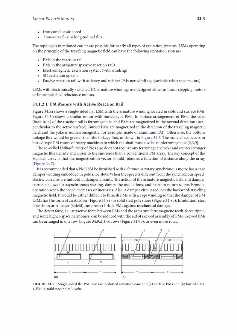
8102019 Power Handbook
httpslidepdfcomreaderfullpower-handbook 2043
34-5Linear Electric Motors
bull Iron cored or air cored
bull ransverse 1047298ux or longitudinal 1047298ux
Te topologies mentioned earlier are possible or nearly all types o excitation systems LSMs operating
on the principle o the traveling magnetic 1047297eld can have the ollowing excitation systems
bull PMs in the reaction railbull PMs in the armature (passive reaction rail)
bull Electromagnetic excitation system (with winding)
bull SC excitation system
bull Passive reaction rail with saliency and neither PMs nor windings (variable reluctance motors)
LSMs with electronically switched DC armature windings are designed either as linear stepping motors
or linear switched reluctance motors
34121 PM Motors with Active Reaction Rail
Figure 345a shows a single-sided 1047298at LSM with the armature winding located in slots and surace PMs
Figure 345b shows a similar motor with buried-type PMs In surace arrangement o PMs the yoke(back iron) o the reaction rail is erromagnetic and PMs are magnetized in the normal direction (per-
pendicular to the active surace) Buried PMs are magnetized in the direction o the traveling magnetic
1047297eld and the yoke is nonerromagnetic or example made o aluminum (Al) Otherwise the bottom
leakage 1047298ux would be greater than the linkage 1047298ux as shown in Figure 346 Te same effect occurs in
buried-type PM rotors o rotary machines in which the shaf must also be nonerromagnetic [239]
Te so-called Halbach array o PMs also does not require any erromagnetic yoke and excites stronger
magnetic 1047298ux density and closer to the sinusoids than a conventional PM array Te key concept o the
Halbach array is that the magnetization vector should rotate as a unction o distance along the array
(Figure 347)
It is recommended that a PM LSM be urnished with a damper A rotary synchronous motor has a cage
damper winding embedded in pole shoe slots When the speed is different rom the synchronous speed
electric currents are induced in damper circuits Te action o the armature magnetic 1047297eld and damper
currents allows or asynchronous starting damps the oscillations and helps to return to synchronous
operation when the speed decreases or increases Also a damper circuit reduces the backward-traveling
magnetic 1047297eld It would be rather difficult to urnish PMs with a cage winding so that the damper o PM
LSMs has the orm o an Al cover (Figure 348a) or solid steel pole shoes (Figure 348b) In addition steel
pole shoes or Al cover (shield) can protect brittle PMs against mechanical damage
Te detent orce ie attractive orce between PMs and the armature erromagnetic teeth orce ripple
and some higher-space harmonics can be reduced with the aid o skewed assembly o PMs Skewed PMs
can be arranged in one row (Figure 349a) two rows (Figure 349b) or even more rows
1 3
(a) (b)
N
S
τ τ
S
N
1 2 3
N S
τ τ
S N
Single-sided 1047298at PM LSMs with slotted armature core and (a) surace PMs and (b) buried PMs
1 PM 2 mild steel pole 3 yoke
8102019 Power Handbook
httpslidepdfcomreaderfullpower-handbook 2143
34-6 Electric Power Generation Transmission and Distribution
(a)
(b)
Magnetic 1047298ux distribution in the longitudinal sections o buried-type PM LSMs (a) nonerromag-
netic yoke and (b) erromagnetic yoke (back iron)
1
2
Double-sided LSM with Halbach array o PMs 1 PMs 2 coreless armature winding
2
2
3(a)
(b)
3
1
1
Dampers o surace-type PM LSMs (a) Al cover (shield) and (b) solid steel pole shoes 1 PM
2 damper 3 yoke
8102019 Power Handbook
httpslidepdfcomreaderfullpower-handbook 2243
34-7Linear Electric Motors
Speci1047297cation data o 1047298at single-sided PM LBMs manuactured by Anorad are shown in able 341 [1]
and motors manuactured by Kollmorgen are shown in able 342 [11] Te temperature 25degC 125degC
or 130degC or the thrust current resistance and power loss is the temperature o the armature winding
Te electromotive orce (EMF) constant kE in ables 341 and 342 or sinusoidal operation is de1047297ned
according to the equation expressing the EMF (induced voltage) excited by PMs without the armature
reaction ie
E k v E s=
(344)
where v s is the synchronous speed according to Equation 341 Tus the armature constant kE multiplied
by the synchronous speed v s gives the EMF E
S SN N N N N N
N N N N N N
N N N N N N
S S S S
S S S S S S
S
(b)
(a)
S S S S S
Skewed PMs in 1047298at LSMs (a) one row and (b) two rows
Flat Tree-Phase Single-Sided PM LBMs with Natural Cooling Systems
Manuactured by Anorad Hauppauge NY
Parameter LCD--1 LCD--2-P LCD--3-P LCD--4-P
Continuous thrust at 25degC N 163 245 327 490
Continuous current at 25degC A 42 63 85 127
Continuous thrust at 125degC N 139 208 277 416
Continuous current at 125degC A 36 54 72 108
Peak thrust (025 s) N 303 455 606 909
Peak current (025 s) A 92 138 184 276
Peak orce (10 s) N 248 373 497 745
Peak current (10 s) A 73 110 147 220Continuous power losses at 125degC W 58 87 115 173
Armature constant kE Vsm 129
Trust constant (three phases) kF NA 386
Resistance per phase at 25degC Ω 32 22 16 11
Inductance mH 143 95 71 48
PM pole pitch mm 2345
Maximum winding temperature degC 125
Armature assembly mass kg 18 24 36 48
PM assembly mass kgm 64
Normal attractive orce N 1036 1555 2073 3109
8102019 Power Handbook
httpslidepdfcomreaderfullpower-handbook 2343
34-8 Electric Power Generation Transmission and Distribution
Te thrust constant kF in ables 341 and 342 is de1047297ned according to the simpli1047297ed equation or the
developed electromagnetic thrust ie
F k I dx F a= cos Ψ
(345)
or a sinusoidally excited LSM with equal reluctances in the d - and q-axes and or the angle between the
armature current I a and the q-axis Ψ = 0deg (cos Ψ = 1) Tus the thrust constant kF times the armature
current I a gives the electromagnetic thrust developed by the LSM
Double-sided 1047298at PM LSMs consist o two external armature systems and one internal excitation sys-
tem (Figure 3410a) or one internal armature system and two external excitation systems (Figure 3410b)
In the second case a linear Grammersquos armature winding can be used
In slotless motors the primary winding is uniormly distributed on a smooth armature core or does
not have any armature core Slotless PM LSMs are detent orcendashree motors provide lower torque ripple
and at high input requency can achieve higher efficiency than slotted LSMs On the other hand larger
nonerromagnetic air gap requires more PM material and the thrust density (thrust per mass or volume)
is lower than that o slotted motors (able 343) Te input current is higher as synchronous reactances
Flat Tree-Phase Single-Sided PM LBMs with Natural Cooling Systems
Manuactured by Kollmorgen Radord VA
Parameter IC11-030 IC11-050 IC11-100 IC11-200
Continuous thrust at 130degC N 150 275 600 1260
Continuous current at 130degC A 40 44 48 50
Peak thrust N 300 500 1000 2000
Peak current A 79 79 79 79
Continuous power losses at 130degC W 64 106 210 418
Armature constant at 25degC kE Vsm 309 514 1028 2057
Trust constant (three phases) at 25degC kF NA 378 629 1259 2519
Resistance line to line at 25degC Ω 19 26 44 80
Inductance line to line mH 173 278 541 1066
Electrical time constant ms 89 105 123 134
Termal resistance winding to external
structure degCW
164 099 050 025
Maximum winding temperature degC 130
Armature assembly mass kg 20 32 62 122PM assembly mass kgm 55 76 128 269
Normal attractive orce N 1440 2430 4900 9850
(a)
N S N SN S N S
N S N SN S N S
(b)
Double-sided 1047298at PM LSMs with (a) two external armature systems and (b) one internal armature
system
8102019 Power Handbook
httpslidepdfcomreaderfullpower-handbook 2443
34-9Linear Electric Motors
in the d - and q-axes can decrease to a low undesired value due to the absence o teeth Figure 3411a
shows a single-sided 1047298at slotless motor with armature core and Figure 3411b shows a double-sided slot-
less motor with inner air-cored armature winding (moving coil motor)
able 344 contains perormance speci1047297cations o double-sided PM LBMs with inner three-phase air-
cored armature winding manuactured by rilogy Systems Corporation Webster X (Figure 3412)
N
(a) (b)
S N S N S N S
S N NS
Flat slotless PM LSMs (a) single-sided with armature core and (b) double-sided with inner air-
cored armature winding
Slotted versus Slotless LSMs
Quantity Slotted LSM Slotless LSM
Higher thrust density X
Higher efficiency in the lower speed range X
Higher efficiency in the higher speed range x
Lower input current X
Less PM material X
Lower winding cost x
Lower thrust pulsations x
Lower acoustic noise x
Flat Double-Sided PM LBMs with Inner Tree-Phase Air-Cored Series-Coil
Armature Winding Manuactured by rilogy Systems Corporation Webster X
Parameter 310-2 310-4 310-6
Continuous thrust N 1112 2091 3149
Continuous power or sinusoidal operation W 87 152 230
Peak thrust N 356 712 1068
Peak power W 900 1800 2700
Peakcontinuous current A 10028 10026 10026
Trust constant kF or sinusoidal operation NA 400 800 1200
Trust constant kF or trapezoidal operation with Hallsensors NA
351 725 1095
Resistance per phase Ω 86 172 258
Inductance plusmn05 mH 60 120 180
Heat dissipation constant or natural cooling WdegC 110 201 301
Heat dissipation constant or orced air cooling WdegC 130 240 355
Heat dissipation constant or liquid cooling WdegC 154 285 421
Number o poles 2 4 6
Coil length mm 1422 2642 3861
Coil mass kg 055 103 153
Mass o PM excitation systems kgm 1267 or 838
8102019 Power Handbook
httpslidepdfcomreaderfullpower-handbook 2543
34-10 Electric Power Generation Transmission and Distribution
By rolling a lat LSM around the axis parallel to the direction o the traveling magnetic ield
ie parallel to the direction o thrust a tubular (cylindrical) LSM can be obtained (Figure 3413) A
tubular PM LSM can also be designed as a double-sided motor or slotless motor
ubular single-sided LSMs LinMoreg with movable internal PM excitation system (slider) and stationaryexternal armature are manuactured by Sulzer Electronics AG Zurich Switzerland (able 345) All active
motor parts bearings position sensors and electronics have been integrated into a rigid metal cylinder [14]
LinMotreg is a registered trademark o Sulzer Electronics AG Zuumlrich Switzerland
(b)(a)
N S N S N S
N S N S N S
N S N S
SNN S
Single-sided slotted tubular PM LSMs (a) with external armature system and (b) with external
excitation system
Data o ubular LSMs LinMotreg Manuactured by Sulzer Electronics AG Zuumlrich Switzerland
Parameter P01 23 times 80 P01 23 times 160 P01 37 times 120 P01 37 times 240
Number o phases 2
PMs NdFeB
Maximum stroke m 0210 0340 1400 1460Maximum orce N 33 60 122 204
Maximum acceleration ms2 280 350 247 268
Maximum speed ms 24 42 40 31
Stator (armature) length m 0177 0257 0227 0347
Stator outer diameter mm 23 23 37 37
Stator mass kg 0265 0450 0740 1385
Slider diameter mm 12 12 20 20
Maximum temperature o the armature winding degC 90
Flat double-sided PM LSM with inner moving coil (Photo courtesy o rilogy Systems Webster X)
8102019 Power Handbook
httpslidepdfcomreaderfullpower-handbook 2643
34-11Linear Electric Motors
All the aorementioned PM LSMs are motors with longitudinal magnetic 1047298ux the lines o which lie
in the plane parallel to the direction o the traveling magnetic 1047297eld LSMs can also be designed as trans-
verse magnetic 1047298ux motors in which the lines o magnetic 1047298ux are perpendicular to the direction o the
traveling 1047297eld Figure 3414a shows a single-sided transverse 1047298ux LSM in which PMs are arranged in two
rows A pair o parallel PMs creates a two pole 1047298ux excitation system A double-sided con1047297guration o
transverse 1047298ux motor is possible however it is complicated and expensive (Figure 3414b)
34122 PM Motors with Passive Reaction Rail
Te drawback o PM LSMs is the large amount o PM material that must be used to design the excitation
system Normally expensive rare-earth PMs are requested I a small PM LSM uses say 10 kg o NdFeB
per 1 m o the reaction rail and 1 kg o good-quality NdFeB costs US$ 130 the cost o the reaction rail
without assembly amounts to US$ 1300 per 1 m Tis price cannot be acceptable or example in pas-
senger transportation systems
A cheaper solution is to apply the PM excitation system to the short armature that magnetizes the
long reaction rail and creates magnetic poles in it Such a linear motor is called the homopolar LSM
Te homopolar LSM as described in [517] is a double-sided AC linear motor that consists o two
polyphase armature systems connected mechanically and magnetically by a erromagnetic U-type yoke
(Figure 3415) Each armature consists o a typical slotted linear motor stack with polyphase armature
winding and PMs located between the stack and U-type yoke Since the armature and excitation systems
are combined together the armature stack is oversized as compared with a conventional steel-cored LSM
Te PMs can also be replaced by electromagnets [1719] Te variable reluctance reaction rail is passive
Te saliency is created by using erromagnetic (solid or laminated) cubes separated by a nonerromag-netic material Te reaction rail poles are magnetized by the armature PMs through the air gap Te trav-
eling magnetic 1047297eld o the polyphase armature winding and salient poles o the reaction rail produce the
thrust Such a homopolar LSM has been proposed or the propulsion o maglev trains o Swissmetro [17]
Further simpli1047297cation o the double-sided con1047297guration can be made to obtain a single-sided PM
LSM shown in Figure 3416
3413 Flux-Switching PM Linear Motors
Large gantry systems and machining centers require powerul linear motors preerably with PM-ree
reaction rail Siemens 1FN6 PM LSMs with a magnet-ree reaction rail belong to the group o the so
5
(a) (b)
5
N S
N
N
3
4
4
3
2
6
1
3
6
1
6
1
i
S
2
2
N
N
SNN
S
ransverse 1047298ux PM LSM (a) single-sided and (b) double-sided 1 armature winding 2 armature
laminated core 3 PM 4 back erromagnetic core 5 magnetic 1047298ux 6 armature current
8102019 Power Handbook
httpslidepdfcomreaderfullpower-handbook 2743
34-12 Electric Power Generation Transmission and Distribution
called 1047298ux-switching PM machines [1016] Te armature system is air cooled degree o protection IP23
class o insulation F line voltage rom 400 to 480 V rated thrust rom 235 to 2110 N maximum veloc-
ity at rated thrust rom 170 to 540 mmin (able 346) overload capacity 38 o rated thrust modular
type construction [20] Tese LSMs operate with Siemens Sinamics or Simodrive solid-state converters
and external encoders According to Siemens [20] these new LSMs produce thrust orces and velocities
equivalent to competitive classical models or light-duty machine tool machine accessory and material
handling applications
2 3 244 1
N
S
S
N
N
S
S
N
5
Single-sided PM LSM with a passive reaction rail 1 PM 2 armature winding 3 armature stack
4 yoke 5 erromagnetic reaction rail
1
1
2 343
5
Fe Fe Fe Fe
Double-sided homopolar PM LSM with passive reaction rail 1 PM 2 armature winding
3 armature stack 4 yoke 5 reaction rail
Speci1047297cations o 1FN6 PM LSMs Manuactured by Siemens Erlangen Germany
Armature Unit Rated Trust N Max Trust N
Max Speed at
Rated Trust
mmin
Max Speed at
Max Trust
mmin
Rated
Current A Max Current A
1FN6008-1LC17 235ndash350 900 263 103 17ndash26 90
1FN6008-1LC37 235ndash350 900 541 224 35ndash53 180
1FN6016-1LC30 470ndash710 1800 419 176 54ndash80 280
1FN6016-1LC17 935ndash1400 3590 263 101 70ndash105 360
1FN6024-1LC12 705ndash1060 2690 176 69 35ndash53 180
1FN6024-1LC20 705ndash1060 2690 277 114 54ndash80 280
1FN6024-1LG10 2110ndash3170 8080 172 62 105ndash160 540
1FN6024-1LG17 2110ndash3170 8080 270 102 162ndash243 840
Source Synchronous Linear Motor 1FN6 Te Electrical Gear Rack Siemens AG Industry Sector Drive echnologies
Motion Control Erlangen Germany 2008
8102019 Power Handbook
httpslidepdfcomreaderfullpower-handbook 2843
34-13Linear Electric Motors
Te magnet-ree reaction rail is easy to install and does not require the saety considerations o stan-
dard PM reaction rails Without PMs there is no problem with errous chips and other debris beingattracted to these sections Maintenance becomes a simple matter o installing a wiper or brush on the
moving part o the slide
Te 1047298ux-switching LSM comprises an armature section that is equipped with coils and PMs as well
as a nonmagnetic toothed reaction rail section (Figure 3417) Te key design innovation is an LSM in
which PMs are integrated directly into the lamination o the armature core along with the individual
windings or each phase Both magnitudes and polarities o the linkage 1047298ux in the armature winding
vary periodically along with the reaction rail movement Te magnetic 1047298ux between the armature core
and steel reaction rail is controlled by switching the three-phase armature currents according to a desig-
nated algorithm Te passive reaction rail consists o milled steel with poles (teeth) and is much simpler
to manuacture
3414 Motors with Electromagnetic Excitation
Te electromagnetic excitation system o an LSM is similar to the salient-pole rotor o a rotary
synchronous motor Figure 3418 shows a 1047298at single-sided LSM with salient erromagnetic poles and
DC 1047297eld excitation winding Te poles and pole shoes can be made o solid steel laminated steel or sin-
tered powder I the electromagnetic excitation system is integrated with the moving part the DC cur-
rent can be delivered with the aid o brushes and contact bars inductive power transer (IP) systems
linear transormers or linear brushless exciters
A AB BC C
1
2
3
4
5
v
τ2
τ1
Construction o 1047298ux-switching LSM with PM-ree reaction rail 1 laminated armature core
2 PM 3 armature coil (phase C) 4 toothed passive steel reaction rail 5 linkage magnetic 1047298ux (phase A is on)
1
3
τ τ
2
S
d d q q q
4
N
Electromagnetic excitation system o a 1047298at single-sided iron-cored LSM 1 salient pole 2 DC
excitation winding 3 erromagnetic rail (yoke) 4 armature system
8102019 Power Handbook
httpslidepdfcomreaderfullpower-handbook 2943
34-14 Electric Power Generation Transmission and Distribution
LSMs with electromagnetic excitation (wound-1047297eld reaction rail) are used in German ransrapid
maglev train (Figure 3419)
3415 Motors with Superconducting Excitation System
In large-power LSMs the electromagnets with erromagnetic core that produce the excitation 1047298ux can
be replaced by coreless SC electromagnets Since the magnetic 1047298ux density produced by the SC electro-
magnet is greater than the saturation magnetic 1047298ux density o the best laminated alloys ( Bsat asymp 24 or
cobalt alloy) there is no need to use the armature erromagnetic core An LSM with SC 1047297eld excitation
system is a totally air-cored machine (Figure 3420)
Experimental maglev trains on the Yamanashi Maglev est Line (YML) in Yamanashi Preecture(west rom okyo) Japan are driven by air-cored LSMs with SC excitation systems ( Figure 3421)
342 Linear Induction Motors
LIMs have ound the widest prospects or applications in transportation systems beginning with electri-
cal traction on small passenger or material supply cars (used at airports exhibitions electrohighways
elevators) and ending with pallet transportation waer transportation belt conveyors transportation
systems o bulk materials etc Te second important place or LIM applications is in industry ie man-
uacturing processes (machine tools hammers presses mills separators automated manuacturing systems
strip tensioners textile shuttles index tables turntables disk saws or wood sliding doors robots etc)
ransrapid 09 maglev train driven by LSMs with electromagnetic excitation (Photo courtesy oTyssen ransrapid System GmbH Munich Germany)
1
2A
B
C B
A
A
C
S SN
τ τ τ τ τ
N N
CBA
Tree-phase air-cored LSM with SC excitation system 1 armature coils 2 SC excitation coils
8102019 Power Handbook
httpslidepdfcomreaderfullpower-handbook 3043
34-15Linear Electric Motors
LIMs can also play an important part in industrial investigations and tests or example high acceleration
o model aircraf in aerodynamic tunnels high acceleration o vessels in laboratory pools propulsion o
mixers shakers and vibrators and adjusting xndashy tables and instruments Tere is also a possibility o
using LIMs in consumer electronics (sound and vision equipment knitting machines curtains) and in
offices (transportation o documents letters and cash) Te Handbook o Linear Motor Applications [21]
printed in Japan in 1986 contains about 50 examples o applications o LIMs in operation or in the pro-
cess o implementation
3421 Basic Geometries and Constructions
A LIM can be obtained by cutting in the same way either a cage rotor induction motor or a wound rotor
induction motor Te stator becomes the primary and the rotor becomes the secondary [12] Te secondary
o a LIM can be simpli1047297ed by using a solid steel core and replacing the cage (ladder) or slip-ring winding with
a high-conductivity nonerromagnetic plate (Al or Cu) Te nonerromagnetic plate is a secondary electric
circuit with distributed parameters and the erromagnetic core is a conductor both or the magnetic 1047298ux
and the electric current It does not matter rom the principle o operation point o view which part (primary
or secondary) is in motion Tus the 1047298at single-sided LIM can be obtained rom a solid rotor induction
motor (Figure 341a) and the 1047298at double-sided LIM can be obtained rom a hollow-rotor induction motor
with wound external and internal stator (Figure 341b) In a double-sided LIM the secondary erromagneticcore is not necessary since the magnetic 1047298ux excited by one o the primary windings afer passing through
the air gaps and nonerromagnetic secondary is then closed up by the core o the second primary unit
Teoretically a double-sided LIM with primary windings located on two cores in comparison with a
single-sided LIM exciting the same MMF has twice the air gap magnetic 1047298ux density Tereore the thrust
o such a motor is our times greater assuming the same dimensions I only one primary core is wound
the output parameters o a double-sided LIM are the same as those or a single-sided LIM with laminated
secondary back iron Te undamental advantage o double-sided LIMs is the elimination o the normal
attractive orce between the primary and the secondary because the secondary is usually nonerromagnetic
Flat LIMs can have primary cores consisting o an array o cores arranged in parallel at appropri-
ate distances and connected magnetically by additional yokes perpendicular to the direction o the
YML in Yamanashi Preecture (near okyo) Japan YML maglev trains use air-cored LSMs
with SC excitation system (Photo courtesy o Central Japan Railway Company and Railway echnical Research
Institute okyo Japan)
8102019 Power Handbook
httpslidepdfcomreaderfullpower-handbook 3143
34-16 Electric Power Generation Transmission and Distribution
traveling 1047297eld A magnetic circuit designed in such a way makes it possible to apply two windings in
general multiphase windings with perpendicular conductors as shown in Figure 3422 Adjusting the
current in each winding the secondary can be moved in two perpendicular directions and can be posi-
tioned at any point o the xndashy plane A 1047298at LIM with two degrees o reedom (DOFs) can be designed both
as single-sided and double-sided machines
By rolling a 1047298at single-sided or double-sided LIM around the axis parallel to the direction o the travel-
ing magnetic 1047297eld ie parallel to the direction o the thrust a tubular motor can be obtained (Figure 3423)
A tubular (cylindrical) LIM similar to a 1047298at LIM can be designed both as single-sided and double-
sided machines and can have a square or rectangular cross section as in Figure 3424 Tere are possible
Te primary o a 1047298at LIM with two DOFs
g
g
g 1
g 2
(c)
(b)
(a)
d
v
v
v
1
1
1 1
1
1
2
2
2
2
2
2
ubular LIMs (a) single-sided with an external short primary (b) single-sided with an external
short secondary and (c) double-sided with short primary 1 primary 2 secondary
8102019 Power Handbook
httpslidepdfcomreaderfullpower-handbook 3243
34-17Linear Electric Motors
con1047297gurations other than that in Figure 3423 regarding the length o the secondary with respect to thelength o the primary
All the aorementioned LIMs are motors with longitudinal magnetic 1047298ux ie the lines o magnetic
1047298ux lie in the plane parallel to the direction o the traveling magnetic 1047297eld A LIM can also be designed
in such a way as to obtain magnetic 1047298ux lines perpendicular to the direction o the traveling 1047297eld Such
motors are said to have transverse magnetic 1047298ux (Figure 3425)
Te undamental advantage o a LIM with transverse magnetic 1047298ux in comparison with a LIM with
longitudinal magnetic 1047298ux is the lower magnetizing current necessary due to the shorter magnetic 1047298ux
paths Te signi1047297cant disadvantage is lower thrust A 1047298at LIM with transverse magnetic 1047298ux usually has
a primary winding o concentrated coils located on salient poles
A 1047298at single-sided LIM with transverse 1047298ux can produce not only thrust but also electrodynamic
suspension In the design shown in Figure 3426 the secondary is suspended electrodynamically andpropelled and stabilized laterally by the primary magnetic 1047297eld [8] Te primary magnetic circuit con-
sists o E-shaped laminations assembled in two rows Te short secondary is made o light Al alloy in the
orm o a boat Te lateral sides o the boat are inclined by 60deg with respect to the active surace Such a
shape provides maximum normal repulsive orce and maximum lateral stabilization
According to their geometry the LIMs can be divided into the ollowing groups
bull With movable primary or movable secondary
bull Single sided and double sided
bull Flat and tubular
bull With short primary and short secondary
bull With longitudinal and transverse magnetic 1047298ux
1 2 3 4 1 2 3 4
ubular double-sided LIM with a square cross section 1 primary 2 secondary 3 primary coil
4 internal core
v
v
1 1
1
1
(a)
(b)
22
22
Flat LIM with transverse magnetic 1047298ux and salient poles (a) single-sided and (b) double-sided
1 primary 2 secondary
8102019 Power Handbook
httpslidepdfcomreaderfullpower-handbook 3343
34-18 Electric Power Generation Transmission and Distribution
Te linear speed o a LIM is
v s v s= minus( )1 (346)
where
s is the slip
v s is the synchronous speed according to Equation 341
Neglecting the longitudinal end effect [6] the electromagnetic thrust developed by a LIM can be
expressed in a similar way as or a rotary induction motor ie
F
m
v I
R
sdx
s
= prime( ) prime1
2
2 2
(347)
where
m1 is the number o phases o the primary winding
v s is the synchronous speed according to Equation 341
primeI 2 is the secondary current reerred to the primary system
primeR2 is the secondary resistance reerred to the primary system
s is the slip
Te secondary resistance primeR2 must include the so-called edge effect [6]
3422 Propulsion of Wheel-on-Rail Vehicles
Modern railway systems and electrical traction should meet the ollowing requirements
bull High level o automatization and computerization
bull Propulsion and braking independent o adhesion which in turn is affected 1047297rst o all by climate
and weather
bull Low level o noise sometimes below 70 dB (A)
Flat LIM with transverse magnetic 1047298ux salient poles and nonerromagnetic secondary pro-
pelled suspended and stabilized electrodynamically (From Gieras JF et al Analytical calculation o electro-
dynamic levitation orces in a special-purpose linear induction motor International Electric Machines and Drives
Conerence (IEMDCrsquo11) Niagara Falls Ontario Canada 2011 [on CD-ROM])
8102019 Power Handbook
httpslidepdfcomreaderfullpower-handbook 3443
34-19Linear Electric Motors
bull Ability to cope with high slopes at least 6 and sharp bends with radius o curvature less than 20 m
bull No pollution to natural environment and landscape
bull High reliability
Te congestion problems o big cities should be solved by creating collective transport orms that can be
implemented without affecting a highly populated city For example there are many cities in Italy where
the historical center has remained the same since the Renaissance A heavy railway might be a com-
pletely wrong solution and have a notable impact on the city planning An adequate solution might be
a light railway a people mover with transport capacity o 10000ndash20000 passengers per hour to replace
the traditional transport nets and to integrate the existing railway nets
All the requirements mentioned earlier can be met by using LIMs as propulsion machines Replacing
electrical rotary motors with linear motors in traction drives (electrical locomotives) generally does
not require new tracks but only their adjustment to linear drives Single-sided LIMs (Figure 3427a and b)
are best since the normal attractive orce o these can strengthen the adhesion o wheels and rails
Te air gap is rom 10 to 15 mm Most requently the motor car has two LIMs with short primaries
(Figure 3427a) assembled in series Te double-layer secondary consists o a solid back iron and an Al
cap and is located between the rails Cables or computer communication with the vehicle and quite
ofen collectors or electrical energy delivery to the vehicle are located along the track Tree-phaseLIMs are ed rom variable-voltage variable-requency (VVVF) voltage-source inverters A linear pro-
pulsion system o wheel-on-rail vehicles allows more 1047298exibility (Figure 3428) reducing noise on bends
and wear o the wheels and rails
Double-sided LIMs (Figure 3427c and d) have ound very limited application due to the technical
difficulty o eliminating aults caused by bends in the secondary with primary cores on either side It is
more difficult to keep a small and uniorm air gap in double-sided LIMs than that in single-sided LIMs
Te LIM-driven wheel-on-rail vehicles are built or low velocities ie less than 100 kmh and or
short routes ie less than 50 km (urban transit systems and short-distance trains) At present LIM-
driven trains operate in oronto and Vancouver BC Canada in Detroit MI (Figure 3429) okyo
(Figure 3430) and Osaka Japan and Kuala Lumpur Malaysia
(a) (b)
(c) (d)
LIM-driven wheel-on-rail cars (a) single-sided LIM with short primary mounted on the undercar-
riage (b) single-sided LIM with short secondary mounted on the undercarriage (c) double-sided LIM with short pri-
mary mounted on the undercarriage and (d) double-sided LIM with short secondary mounted on the undercarriage
8102019 Power Handbook
httpslidepdfcomreaderfullpower-handbook 3543
34-20 Electric Power Generation Transmission and Distribution
(a) (b)
Te undercarriage o a wheel-on-rail vehicle (a) rotary motor propulsion and (b) LIM propulsion
Detroit people mover driven by single-sided LIMs
oei Oedo subway line in okyo driven by single-sided LIMs
8102019 Power Handbook
httpslidepdfcomreaderfullpower-handbook 3643
34-21Linear Electric Motors
Te design data o some single-sided traction LIMs are presented in able 347 and double-sided trac-
tion LIMs in able 348
343 Variable Reluctance Motors
Te simplest construction o a variable reluctance LSM or linear reluctance motor (LRM) is that shown
in Figure 3418 with DC excitation winding being removed However the thrust o such a motor wouldbe low as the ratio o d -axis permeance to q-axis permeance is low Better perormance can be obtained
when using 1047298ux barriers [18] or steel laminations [15] o make 1047298ux barriers any nonerromagnetic
materials can be used o obtain high permeance (low reluctance) in the d -axis and low permeance in
the q-axis steel laminations should be oriented in such a way as to create high permeance or the d -axis
magnetic 1047298ux
Figure 3431a shows a variable reluctance platen with 1047298ux barriers and Figure 3431b shows how to
arrange steel laminations to obtain different reluctances in the d - and q-axes Te platen can be com-
posed o segments the length o which is equal to the pole pitchτ Each segment consists o semicircular
lamellas cut out rom electrotechnical sheet A 1047297lling or example epoxy resin is used to make the seg-
ment rigid and robust By putting the segments together a platen o any desired length can be obtained
Design Data o Single-Sided Tree-Phase LIMs or Propulsion o Vehicles
Quantity
LIM
UnitJLMDR ICS KU CIGG GEC
Pullout thrust at requency given
in the ollowing F x
125 90 35 17 07 kN
Input requency 200 400 250 400 600 Hz
Rated phase current V 1 2750 4650 1300 2000 2000 A
Number o poles 2 p 8 6 4 6 4 mdash
Number o turns per phase N 1 128 96 128 108 48 mdash
Equivalent diameter o conductor d 1 mdash 893 528 1115 81 mm
Number o parallel conductors mdash 1 mdash 19 1 mdash
Effective width o primary core Li 023 0216 029 0101 01715 m
Pole pitch τ 027 02868 030 025 020 m
Length o single end connection l e mdash 03483 mdash 02955 03685 m
Coil pitch wc 0225 01673 025 01944 01555 m
Air gap g 150 126 120 150 182 mm
Number o slots z 1( primez 1) 96(106) 72(79) 48(58) 54(61) 36(43) mdash
Width o slot b11 mdash 156 170 150 1308 mm
Width o slot opening b14 mdash 156 mdash 1044 1308 mm
Depth o slot h11 mdash 530 380 3421 6147 mm
Height o yoke h1 y mdash 436 393 7163 500 mm
Conductivity o back iron at 20degC σFe mdash 446 952 446 512 times106 Sm
Conductivity o Al cap at 20degC σ Al mdash 300 303 323 215 times106 Sm
Width o back iron w 03 024 03 0111 01715 m
Tickness o back iron hsec 190 125 250 254 474 mm
Tickness o Al cap d 50 45 50 45(25) 32 mm
Tickness o Al cap behind Fe core t ov 50 170 50 127 32 mm
Width o Al cap 030 032 040 0201 02985 m
JLMDR Japanese Linear Motor Driven Railcar Japan ICS Intermediate Capacity ransit System Canada KU
Kyushu University LIM Japan CIGG Canadian Inst o Guided Ground ransport Canada GEC General
Electric Company United States (z 1 ) is the number o hal 1047297lled slots
8102019 Power Handbook
httpslidepdfcomreaderfullpower-handbook 3743
34-22 Electric Power Generation Transmission and Distribution
344 Stepping Motors
A linear stepping motor has a concentrated armature winding wound on salient poles and PM excitation
rail or variable reluctance platen Te thrust is generated as an action o the armature magnetic 1047298ux and
PM 1047298ux (active platen) or the armature magnetic 1047298ux and salient erromagnetic poles (variable reluc-
tance platen) Stepping motors have no position eedback
Design Data o Double-Sided Tree-Phase LIMs or Propulsion
o Vehicles
Quantity
LIM
UnitGEC LIMVR
Maximum thrust at input requency F x given in the ollowing 085 1668 kN
Input requency 600 1730 Hz
Input phase current I 1 2000 20000 A
Number o poles 2 p 4 10 mdash
Number o turns per phase N 1 144 100 mdash
Diameter o conductor d 1 075 110 mm
Effective width o primary core Li 00869 0254 m
Pole pitch τ 01795 03556 m
Coil pitch wc 005 005 m
Number o slots z 1( primez 1) 36(45) 150(160) mdash
Width o slot b11 137 160 mm
Width o slot opening b14 137 mdash mm
Depth o slot h1 630 mdash mm
Height o yoke h1 y 239 mdash mm
Width o tooth c1 200 77 mm
Resultant air gap 2 g + d 381 38075 mm
Air gap g 2 times 127 2 times 111 mm
Tickness o secondary d 127 15875(hollow) mm
Effective thickness o Al secondary 127 72 mm
Width o secondary w ge03046 mdash m
Conductivity o Al cap at 20degC σ Al asymp2434 asymp240 times106 Sm
GEC General Electric Company United States LIMVR LIM Research Vehicle
Pueblo CO United States (z 1 ) is the number o hal 1047297lled slots
(a) (b)
q q d d d q d q d d
Laminations
τ τ τ τ
Epoxy resin
Variable reluctance LSMs with (a) 1047298ux barriers and (b) steel laminations
8102019 Power Handbook
httpslidepdfcomreaderfullpower-handbook 3843
8102019 Power Handbook
httpslidepdfcomreaderfullpower-handbook 3943
34-24 Electric Power Generation Transmission and Distribution
Tis value is different or ull-step and microstepping drives Te maximum startndashstop speed is the
maximum speed that can be used when starting or stopping the motor without ramping that does not
cause the motor to all out o synchronism or lose steps Te maximum speed is the maximum linear
speed that can be achieved without the motor stalling or alling out o synchronism Te maximum
load mass is the maximum allowable mass applied to the orcer against the scale that does not result in
mechanical damage Te ull-step resolution is the position increment obtained when the currents are
switched rom one winding to the next winding Tis is the typical resolution obtained with ul l-step
drives and it is strictly a unction o the motor construction Te microstepping resolution is the position
increment obtained when the ull-step resolution is divided electronically by proportioning the currents
in the two windings Tis resolution is typically 10ndash250 times smaller than the ull-step resolution [13]
HLSMs are regarded as an excellent solution to positioning systems that require a high accuracy
and rapid acceleration With a microprocessor controlled microstepping mode a smooth operation with
standard resolution o a ew hundred stepsmm can be obtained Te advantages such as high efficiencyhigh throughput mechanical simplicity high reliability precise open-loop operation and low inertia
o the system have made these kind o motors more and more attractive in such applications as actory
automation high speed positioning computer peripherals acsimile machines numerically controlled
machine tools automated medical equipment automated laboratory equipment and welding robots
Tis motor is especially suitable or machine tools printers plotters and computer-controlled material
handling in which a high positioning accuracy and repeatability are the key problems
When two or our orcers mounted at 90deg and a special grooved platen (ldquowaffle platerdquo) are used the
xndashy motion (two DOFs) in a single plane is obtained (Figure 3434)
Speci1047297cation data o the xndashy HLSMs manuactured by Normag Northern Magnetics Inc Santa
Clarita CA are given in able 3410
PM linear stepping motors (Photo courtesy o okyo Aircraf Instrument Co Ltd okyo Japan)
8102019 Power Handbook
httpslidepdfcomreaderfullpower-handbook 4043
34-25Linear Electric Motors
345 Switched Reluctance Motors
Te topology o a linear switched reluctance motor is similar to that o a stepping motor with variable
reluctance platen In addition it is equipped with position sensors Te turn-on and turn-off instant o
the input current is synchronized with the position o the moving part Te thrust is very sensitive to
the turn-on and turn-off instant
In the case o a linear stepping or linear switched reluctance motor the speed v o the moving part is
v v s sw= = τ
(348)
where
sw is the undamental switching requency in one armature phase winding
τ is the pole pitch o the reaction rail
For a rotary stepping or switched reluctance motor sw = 2 pr n where 2 pr is the number o rotor poles and
n is rotational speed in revs
A linear switched reluctance motor has a doubly salient magnetic circuit with a polyphase winding
on the armature Longitudinal and transverse 1047298ux designs are shown in Figure 3435 A linear switched
reluctance motor allows precise speed and position-controlled linear motion at low speeds and is not sub-
ject to design constraints (minimum speed limited by minimum easible pole pitch) o linear AC motors
x
y
12
3
4
1
1
2
2
HLSM with a our-unit orcer to obtain the xndashy motion 1 orcers or the x -direction 2 orcers
or the y -direction 3 platen 4 air pressure
Data o xndashy HLSMs Manuactured by Normag Northern Magnetics Inc
Santa Clarita CA
Parameter 4XY0602-2-0 4XY2002-2-0 4XY2004-2-0 4XY2504-2-0
Number o orcer units per axis 1 1 2 2
Number o phases 2 2 2(4) 2(4)Static thrust N 133 400 980 1330
Trust at 1 ms N 111 311 712 980
Normal attractive orce N 1600 4000 14400 18000
Resistance per phase Ω 29 33 16 19
Inductance per phase mH 15 40 20 23
Input phase current A 20 20 40 40
Air gap mm 002
Maximum temperature degC 110
Mass kg 32 072 20 15
Repeatability mm 000254
Resolution mm 000254
Bearing type Air
8102019 Power Handbook
httpslidepdfcomreaderfullpower-handbook 4143
34-26 Electric Power Generation Transmission and Distribution
346 Linear Positioning Stages
Linear motors are now playing a key role in advanced precision linear positioning Linear precision posi-
tioning systems can be classi1047297ed into open-loop systems with HLSMs and closed-loop servo systems
with LSMs LBMs or LIMs
A PM LSMndashdriven positioning stage is shown in Figure 3436 A stationary base is made o Al steel
ceramic or granite plate It provides a stable precise and 1047298at platorm to which all stationary position-
ing components are attached Te base o the stage is attached to the host system with the aid o mount-
ing screws
Te moving table accommodates all moving positioning components o achieve maximum accelera-
tion the mass o the moving table should be as small as possible and usually Al is used as a lightweight
material A number o mounting holes on the moving table is necessary to 1047297x the payload to the mount-
ing table
Linear bearing rails provide a precise guidance to the moving table A minimum o one bearing rail
is required Linear ball bearing or air bearings are attached to each rail
Te armature o a linear motor is astened to the moving table and reaction rail (PM excitation sys-tem) is built in the base between the rails (Figure 3436)
A linear encoder is needed to obtain precise control o position o the table velocity and acceleration
Te read head o the encoder is attached to the moving table
(a) (b)
3
3
221
1
Linear switched reluctance motor con1047297gurations (a) longitudinal 1047298ux design and (b) transverse
1047298ux design 1 armature winding 2 armature stack 3 platen
12
3
5
4
7
6
8
Linear positioning stage driven by PM LBM 1 base 2 moving table 3 armature o LBM 4 PMs
5 linear bearing 6 encoder 7 cable carrier 8 limit switch (Courtesy o Normag Santa Clarita CA)
8102019 Power Handbook
httpslidepdfcomreaderfullpower-handbook 4243
34-27Linear Electric Motors
Noncontact limit switches ixed to the base provide an overtravel protection and init ial homing
A cable carrier accommodates and routes electrical cables between the moving table and stationary
connector box 1047297xed to the base
An HLSM-driven linear precision stage is o similar construction Instead o PMs between bearing
rails it has a variable reluctance platen HLSMs usually need air bearings and in addition to the electri-
cal cables an air hose between air bearings and the compressor is requiredLinear positioning stages are used in semiconductor technology electronic assembly quality assur-
ance laser cutting optical scanning water jet cutting gantry systems (x y z stages) color printers
plotters and Cartesian coordinate robotics
References
1 Anorad Linear Motors Inormation Brochure Anorad Hauppauge New York 2007 wwwanoradcom
2 Boldea I and Nasar SA Linear Motion Electromagnetic Systems John Wiley amp Sons New York 1985
3 Boldea I and Nasar SA Linear Electric Actuators and Generators Cambridge University Press
New York 2005
4 Compumotor Digiplan Positioning Control Systems and Drives Parker Hanni1047297n CorporationRohnert Park CA 2011
5 Everes W Henneberger G Wunderlich H and Selig A A linear homopolar motor or a trans-
portation system 2nd International Symposium on Linear Drives or Industry Applications (LDIArsquo98)
okyo Japan 1998 pp 46ndash49
6 Gieras JF Linear Induction Drives Clarendon Press Oxord UK 1994
7 Gieras JF Status o linear motors in the United States International Symposium on Linear Drives
or Industry Applications (LDIArsquo03) Birmingham UK 2003 pp 169ndash176
8 Gieras JF Gientkowski Z Mews J and Splawski P Analytical calculation o electrodynamic
levitation orces in a special-purpose linear induction motor International Electric Machines and
Drives Conerence (IEMDCrsquo11) Niagara Falls Ontario Canada 2011 [on CD-ROM]
9 Gieras JF Piech ZJ and omczuk BZ Linear Synchronous Motors ransportation and Automation Systems aylor amp Francis (CRC Press) Boca Raton FL 2011
10 Hoang E Ahmed AHB and Lucidarme J Switching 1047298ux permanent magnet polyphase syn-
chronous machines 7th European Conerence on Power Electronics and Applications (EPErsquo97)
Vol 3 rondheim Norway 1977 pp 903ndash908
11 Kollmorgen Linear Motors Aim to Cut Cost o Semiconductors and Electronics Manuacture
Kollmorgen Radord VA 1997
12 Laithwaite ER A History o Linear Electric Motors Macmillan London UK 1987
13 Linear Step Motor Inormation Brochure okyo Aircraf Instrument Co Ltd okyo Japan
1998
14 LinMot Design Manual Sulzer Electronics Ltd Zuumlrich Switzerland 1999
15 Locci N and Marongiu I Modelling and testing a new linear reluctance motor InternationalConerence on Electrical Machines (ICEMrsquo92) Vol 2 Manchester UK 1992 pp 706ndash710
16 Rauch SE and Johnson LJ Design principles o 1047298ux-switch alternators AIEE rans Part III
74(12) 1261ndash1269 1955
17 Rosenmayr M Casat Glavitsch A and Stemmler H SwissmetromdashPower supply or a high-
power-propulsion system with short stator linear motors 15th International Conerence on
Magnetically Levitated Systems and Linear Drives Maglevrsquo98 Mount Fuji Yamanashi Japan 1998
pp 280ndash286
18 Sanada M Morimoto S and akeda Y Reluctance equalization design o multi 1047298ux barrier con-
struction or linear synchronous reluctance motors 2nd International Symposium on Linear Drives
or Industrial Applications (LDIArsquo98) okyo Japan 1998 pp 259ndash262
8102019 Power Handbook
httpslidepdfcomreaderfullpower-handbook 4343
34-28 Electric Power Generation Transmission and Distribution
19 Seok-Myeong J and Sang-Sub J Design and analysis o the linear homopolar synchronous motor
or integrated magnetic propulsion and suspension 2nd International Symposium on Linear Drives
or Industrial Applications (LDIArsquo98) okyo Japan 1998 pp 74ndash77
20 Synchronous Linear Motor 1FN6 Te Electrical Gear Rack Siemens AG Industry Sector Drive
echnologies Motion Control Erlangen Germany 2008
21 Yamada H Handbook o Linear Motor Applications (in Japanese) Kogyo Chosaki Publishing Cookyo Japan 1986
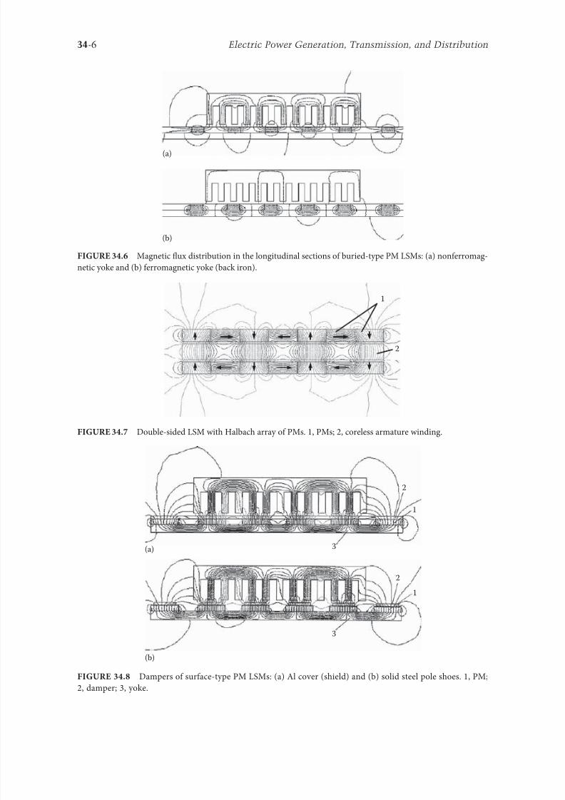
8102019 Power Handbook
httpslidepdfcomreaderfullpower-handbook 2143
34-6 Electric Power Generation Transmission and Distribution
(a)
(b)
Magnetic 1047298ux distribution in the longitudinal sections o buried-type PM LSMs (a) nonerromag-
netic yoke and (b) erromagnetic yoke (back iron)
1
2
Double-sided LSM with Halbach array o PMs 1 PMs 2 coreless armature winding
2
2
3(a)
(b)
3
1
1
Dampers o surace-type PM LSMs (a) Al cover (shield) and (b) solid steel pole shoes 1 PM
2 damper 3 yoke
8102019 Power Handbook
httpslidepdfcomreaderfullpower-handbook 2243
34-7Linear Electric Motors
Speci1047297cation data o 1047298at single-sided PM LBMs manuactured by Anorad are shown in able 341 [1]
and motors manuactured by Kollmorgen are shown in able 342 [11] Te temperature 25degC 125degC
or 130degC or the thrust current resistance and power loss is the temperature o the armature winding
Te electromotive orce (EMF) constant kE in ables 341 and 342 or sinusoidal operation is de1047297ned
according to the equation expressing the EMF (induced voltage) excited by PMs without the armature
reaction ie
E k v E s=
(344)
where v s is the synchronous speed according to Equation 341 Tus the armature constant kE multiplied
by the synchronous speed v s gives the EMF E
S SN N N N N N
N N N N N N
N N N N N N
S S S S
S S S S S S
S
(b)
(a)
S S S S S
Skewed PMs in 1047298at LSMs (a) one row and (b) two rows
Flat Tree-Phase Single-Sided PM LBMs with Natural Cooling Systems
Manuactured by Anorad Hauppauge NY
Parameter LCD--1 LCD--2-P LCD--3-P LCD--4-P
Continuous thrust at 25degC N 163 245 327 490
Continuous current at 25degC A 42 63 85 127
Continuous thrust at 125degC N 139 208 277 416
Continuous current at 125degC A 36 54 72 108
Peak thrust (025 s) N 303 455 606 909
Peak current (025 s) A 92 138 184 276
Peak orce (10 s) N 248 373 497 745
Peak current (10 s) A 73 110 147 220Continuous power losses at 125degC W 58 87 115 173
Armature constant kE Vsm 129
Trust constant (three phases) kF NA 386
Resistance per phase at 25degC Ω 32 22 16 11
Inductance mH 143 95 71 48
PM pole pitch mm 2345
Maximum winding temperature degC 125
Armature assembly mass kg 18 24 36 48
PM assembly mass kgm 64
Normal attractive orce N 1036 1555 2073 3109
8102019 Power Handbook
httpslidepdfcomreaderfullpower-handbook 2343
34-8 Electric Power Generation Transmission and Distribution
Te thrust constant kF in ables 341 and 342 is de1047297ned according to the simpli1047297ed equation or the
developed electromagnetic thrust ie
F k I dx F a= cos Ψ
(345)
or a sinusoidally excited LSM with equal reluctances in the d - and q-axes and or the angle between the
armature current I a and the q-axis Ψ = 0deg (cos Ψ = 1) Tus the thrust constant kF times the armature
current I a gives the electromagnetic thrust developed by the LSM
Double-sided 1047298at PM LSMs consist o two external armature systems and one internal excitation sys-
tem (Figure 3410a) or one internal armature system and two external excitation systems (Figure 3410b)
In the second case a linear Grammersquos armature winding can be used
In slotless motors the primary winding is uniormly distributed on a smooth armature core or does
not have any armature core Slotless PM LSMs are detent orcendashree motors provide lower torque ripple
and at high input requency can achieve higher efficiency than slotted LSMs On the other hand larger
nonerromagnetic air gap requires more PM material and the thrust density (thrust per mass or volume)
is lower than that o slotted motors (able 343) Te input current is higher as synchronous reactances
Flat Tree-Phase Single-Sided PM LBMs with Natural Cooling Systems
Manuactured by Kollmorgen Radord VA
Parameter IC11-030 IC11-050 IC11-100 IC11-200
Continuous thrust at 130degC N 150 275 600 1260
Continuous current at 130degC A 40 44 48 50
Peak thrust N 300 500 1000 2000
Peak current A 79 79 79 79
Continuous power losses at 130degC W 64 106 210 418
Armature constant at 25degC kE Vsm 309 514 1028 2057
Trust constant (three phases) at 25degC kF NA 378 629 1259 2519
Resistance line to line at 25degC Ω 19 26 44 80
Inductance line to line mH 173 278 541 1066
Electrical time constant ms 89 105 123 134
Termal resistance winding to external
structure degCW
164 099 050 025
Maximum winding temperature degC 130
Armature assembly mass kg 20 32 62 122PM assembly mass kgm 55 76 128 269
Normal attractive orce N 1440 2430 4900 9850
(a)
N S N SN S N S
N S N SN S N S
(b)
Double-sided 1047298at PM LSMs with (a) two external armature systems and (b) one internal armature
system
8102019 Power Handbook
httpslidepdfcomreaderfullpower-handbook 2443
34-9Linear Electric Motors
in the d - and q-axes can decrease to a low undesired value due to the absence o teeth Figure 3411a
shows a single-sided 1047298at slotless motor with armature core and Figure 3411b shows a double-sided slot-
less motor with inner air-cored armature winding (moving coil motor)
able 344 contains perormance speci1047297cations o double-sided PM LBMs with inner three-phase air-
cored armature winding manuactured by rilogy Systems Corporation Webster X (Figure 3412)
N
(a) (b)
S N S N S N S
S N NS
Flat slotless PM LSMs (a) single-sided with armature core and (b) double-sided with inner air-
cored armature winding
Slotted versus Slotless LSMs
Quantity Slotted LSM Slotless LSM
Higher thrust density X
Higher efficiency in the lower speed range X
Higher efficiency in the higher speed range x
Lower input current X
Less PM material X
Lower winding cost x
Lower thrust pulsations x
Lower acoustic noise x
Flat Double-Sided PM LBMs with Inner Tree-Phase Air-Cored Series-Coil
Armature Winding Manuactured by rilogy Systems Corporation Webster X
Parameter 310-2 310-4 310-6
Continuous thrust N 1112 2091 3149
Continuous power or sinusoidal operation W 87 152 230
Peak thrust N 356 712 1068
Peak power W 900 1800 2700
Peakcontinuous current A 10028 10026 10026
Trust constant kF or sinusoidal operation NA 400 800 1200
Trust constant kF or trapezoidal operation with Hallsensors NA
351 725 1095
Resistance per phase Ω 86 172 258
Inductance plusmn05 mH 60 120 180
Heat dissipation constant or natural cooling WdegC 110 201 301
Heat dissipation constant or orced air cooling WdegC 130 240 355
Heat dissipation constant or liquid cooling WdegC 154 285 421
Number o poles 2 4 6
Coil length mm 1422 2642 3861
Coil mass kg 055 103 153
Mass o PM excitation systems kgm 1267 or 838
8102019 Power Handbook
httpslidepdfcomreaderfullpower-handbook 2543
34-10 Electric Power Generation Transmission and Distribution
By rolling a lat LSM around the axis parallel to the direction o the traveling magnetic ield
ie parallel to the direction o thrust a tubular (cylindrical) LSM can be obtained (Figure 3413) A
tubular PM LSM can also be designed as a double-sided motor or slotless motor
ubular single-sided LSMs LinMoreg with movable internal PM excitation system (slider) and stationaryexternal armature are manuactured by Sulzer Electronics AG Zurich Switzerland (able 345) All active
motor parts bearings position sensors and electronics have been integrated into a rigid metal cylinder [14]
LinMotreg is a registered trademark o Sulzer Electronics AG Zuumlrich Switzerland
(b)(a)
N S N S N S
N S N S N S
N S N S
SNN S
Single-sided slotted tubular PM LSMs (a) with external armature system and (b) with external
excitation system
Data o ubular LSMs LinMotreg Manuactured by Sulzer Electronics AG Zuumlrich Switzerland
Parameter P01 23 times 80 P01 23 times 160 P01 37 times 120 P01 37 times 240
Number o phases 2
PMs NdFeB
Maximum stroke m 0210 0340 1400 1460Maximum orce N 33 60 122 204
Maximum acceleration ms2 280 350 247 268
Maximum speed ms 24 42 40 31
Stator (armature) length m 0177 0257 0227 0347
Stator outer diameter mm 23 23 37 37
Stator mass kg 0265 0450 0740 1385
Slider diameter mm 12 12 20 20
Maximum temperature o the armature winding degC 90
Flat double-sided PM LSM with inner moving coil (Photo courtesy o rilogy Systems Webster X)
8102019 Power Handbook
httpslidepdfcomreaderfullpower-handbook 2643
34-11Linear Electric Motors
All the aorementioned PM LSMs are motors with longitudinal magnetic 1047298ux the lines o which lie
in the plane parallel to the direction o the traveling magnetic 1047297eld LSMs can also be designed as trans-
verse magnetic 1047298ux motors in which the lines o magnetic 1047298ux are perpendicular to the direction o the
traveling 1047297eld Figure 3414a shows a single-sided transverse 1047298ux LSM in which PMs are arranged in two
rows A pair o parallel PMs creates a two pole 1047298ux excitation system A double-sided con1047297guration o
transverse 1047298ux motor is possible however it is complicated and expensive (Figure 3414b)
34122 PM Motors with Passive Reaction Rail
Te drawback o PM LSMs is the large amount o PM material that must be used to design the excitation
system Normally expensive rare-earth PMs are requested I a small PM LSM uses say 10 kg o NdFeB
per 1 m o the reaction rail and 1 kg o good-quality NdFeB costs US$ 130 the cost o the reaction rail
without assembly amounts to US$ 1300 per 1 m Tis price cannot be acceptable or example in pas-
senger transportation systems
A cheaper solution is to apply the PM excitation system to the short armature that magnetizes the
long reaction rail and creates magnetic poles in it Such a linear motor is called the homopolar LSM
Te homopolar LSM as described in [517] is a double-sided AC linear motor that consists o two
polyphase armature systems connected mechanically and magnetically by a erromagnetic U-type yoke
(Figure 3415) Each armature consists o a typical slotted linear motor stack with polyphase armature
winding and PMs located between the stack and U-type yoke Since the armature and excitation systems
are combined together the armature stack is oversized as compared with a conventional steel-cored LSM
Te PMs can also be replaced by electromagnets [1719] Te variable reluctance reaction rail is passive
Te saliency is created by using erromagnetic (solid or laminated) cubes separated by a nonerromag-netic material Te reaction rail poles are magnetized by the armature PMs through the air gap Te trav-
eling magnetic 1047297eld o the polyphase armature winding and salient poles o the reaction rail produce the
thrust Such a homopolar LSM has been proposed or the propulsion o maglev trains o Swissmetro [17]
Further simpli1047297cation o the double-sided con1047297guration can be made to obtain a single-sided PM
LSM shown in Figure 3416
3413 Flux-Switching PM Linear Motors
Large gantry systems and machining centers require powerul linear motors preerably with PM-ree
reaction rail Siemens 1FN6 PM LSMs with a magnet-ree reaction rail belong to the group o the so
5
(a) (b)
5
N S
N
N
3
4
4
3
2
6
1
3
6
1
6
1
i
S
2
2
N
N
SNN
S
ransverse 1047298ux PM LSM (a) single-sided and (b) double-sided 1 armature winding 2 armature
laminated core 3 PM 4 back erromagnetic core 5 magnetic 1047298ux 6 armature current
8102019 Power Handbook
httpslidepdfcomreaderfullpower-handbook 2743
34-12 Electric Power Generation Transmission and Distribution
called 1047298ux-switching PM machines [1016] Te armature system is air cooled degree o protection IP23
class o insulation F line voltage rom 400 to 480 V rated thrust rom 235 to 2110 N maximum veloc-
ity at rated thrust rom 170 to 540 mmin (able 346) overload capacity 38 o rated thrust modular
type construction [20] Tese LSMs operate with Siemens Sinamics or Simodrive solid-state converters
and external encoders According to Siemens [20] these new LSMs produce thrust orces and velocities
equivalent to competitive classical models or light-duty machine tool machine accessory and material
handling applications
2 3 244 1
N
S
S
N
N
S
S
N
5
Single-sided PM LSM with a passive reaction rail 1 PM 2 armature winding 3 armature stack
4 yoke 5 erromagnetic reaction rail
1
1
2 343
5
Fe Fe Fe Fe
Double-sided homopolar PM LSM with passive reaction rail 1 PM 2 armature winding
3 armature stack 4 yoke 5 reaction rail
Speci1047297cations o 1FN6 PM LSMs Manuactured by Siemens Erlangen Germany
Armature Unit Rated Trust N Max Trust N
Max Speed at
Rated Trust
mmin
Max Speed at
Max Trust
mmin
Rated
Current A Max Current A
1FN6008-1LC17 235ndash350 900 263 103 17ndash26 90
1FN6008-1LC37 235ndash350 900 541 224 35ndash53 180
1FN6016-1LC30 470ndash710 1800 419 176 54ndash80 280
1FN6016-1LC17 935ndash1400 3590 263 101 70ndash105 360
1FN6024-1LC12 705ndash1060 2690 176 69 35ndash53 180
1FN6024-1LC20 705ndash1060 2690 277 114 54ndash80 280
1FN6024-1LG10 2110ndash3170 8080 172 62 105ndash160 540
1FN6024-1LG17 2110ndash3170 8080 270 102 162ndash243 840
Source Synchronous Linear Motor 1FN6 Te Electrical Gear Rack Siemens AG Industry Sector Drive echnologies
Motion Control Erlangen Germany 2008
8102019 Power Handbook
httpslidepdfcomreaderfullpower-handbook 2843
34-13Linear Electric Motors
Te magnet-ree reaction rail is easy to install and does not require the saety considerations o stan-
dard PM reaction rails Without PMs there is no problem with errous chips and other debris beingattracted to these sections Maintenance becomes a simple matter o installing a wiper or brush on the
moving part o the slide
Te 1047298ux-switching LSM comprises an armature section that is equipped with coils and PMs as well
as a nonmagnetic toothed reaction rail section (Figure 3417) Te key design innovation is an LSM in
which PMs are integrated directly into the lamination o the armature core along with the individual
windings or each phase Both magnitudes and polarities o the linkage 1047298ux in the armature winding
vary periodically along with the reaction rail movement Te magnetic 1047298ux between the armature core
and steel reaction rail is controlled by switching the three-phase armature currents according to a desig-
nated algorithm Te passive reaction rail consists o milled steel with poles (teeth) and is much simpler
to manuacture
3414 Motors with Electromagnetic Excitation
Te electromagnetic excitation system o an LSM is similar to the salient-pole rotor o a rotary
synchronous motor Figure 3418 shows a 1047298at single-sided LSM with salient erromagnetic poles and
DC 1047297eld excitation winding Te poles and pole shoes can be made o solid steel laminated steel or sin-
tered powder I the electromagnetic excitation system is integrated with the moving part the DC cur-
rent can be delivered with the aid o brushes and contact bars inductive power transer (IP) systems
linear transormers or linear brushless exciters
A AB BC C
1
2
3
4
5
v
τ2
τ1
Construction o 1047298ux-switching LSM with PM-ree reaction rail 1 laminated armature core
2 PM 3 armature coil (phase C) 4 toothed passive steel reaction rail 5 linkage magnetic 1047298ux (phase A is on)
1
3
τ τ
2
S
d d q q q
4
N
Electromagnetic excitation system o a 1047298at single-sided iron-cored LSM 1 salient pole 2 DC
excitation winding 3 erromagnetic rail (yoke) 4 armature system
8102019 Power Handbook
httpslidepdfcomreaderfullpower-handbook 2943
34-14 Electric Power Generation Transmission and Distribution
LSMs with electromagnetic excitation (wound-1047297eld reaction rail) are used in German ransrapid
maglev train (Figure 3419)
3415 Motors with Superconducting Excitation System
In large-power LSMs the electromagnets with erromagnetic core that produce the excitation 1047298ux can
be replaced by coreless SC electromagnets Since the magnetic 1047298ux density produced by the SC electro-
magnet is greater than the saturation magnetic 1047298ux density o the best laminated alloys ( Bsat asymp 24 or
cobalt alloy) there is no need to use the armature erromagnetic core An LSM with SC 1047297eld excitation
system is a totally air-cored machine (Figure 3420)
Experimental maglev trains on the Yamanashi Maglev est Line (YML) in Yamanashi Preecture(west rom okyo) Japan are driven by air-cored LSMs with SC excitation systems ( Figure 3421)
342 Linear Induction Motors
LIMs have ound the widest prospects or applications in transportation systems beginning with electri-
cal traction on small passenger or material supply cars (used at airports exhibitions electrohighways
elevators) and ending with pallet transportation waer transportation belt conveyors transportation
systems o bulk materials etc Te second important place or LIM applications is in industry ie man-
uacturing processes (machine tools hammers presses mills separators automated manuacturing systems
strip tensioners textile shuttles index tables turntables disk saws or wood sliding doors robots etc)
ransrapid 09 maglev train driven by LSMs with electromagnetic excitation (Photo courtesy oTyssen ransrapid System GmbH Munich Germany)
1
2A
B
C B
A
A
C
S SN
τ τ τ τ τ
N N
CBA
Tree-phase air-cored LSM with SC excitation system 1 armature coils 2 SC excitation coils
8102019 Power Handbook
httpslidepdfcomreaderfullpower-handbook 3043
34-15Linear Electric Motors
LIMs can also play an important part in industrial investigations and tests or example high acceleration
o model aircraf in aerodynamic tunnels high acceleration o vessels in laboratory pools propulsion o
mixers shakers and vibrators and adjusting xndashy tables and instruments Tere is also a possibility o
using LIMs in consumer electronics (sound and vision equipment knitting machines curtains) and in
offices (transportation o documents letters and cash) Te Handbook o Linear Motor Applications [21]
printed in Japan in 1986 contains about 50 examples o applications o LIMs in operation or in the pro-
cess o implementation
3421 Basic Geometries and Constructions
A LIM can be obtained by cutting in the same way either a cage rotor induction motor or a wound rotor
induction motor Te stator becomes the primary and the rotor becomes the secondary [12] Te secondary
o a LIM can be simpli1047297ed by using a solid steel core and replacing the cage (ladder) or slip-ring winding with
a high-conductivity nonerromagnetic plate (Al or Cu) Te nonerromagnetic plate is a secondary electric
circuit with distributed parameters and the erromagnetic core is a conductor both or the magnetic 1047298ux
and the electric current It does not matter rom the principle o operation point o view which part (primary
or secondary) is in motion Tus the 1047298at single-sided LIM can be obtained rom a solid rotor induction
motor (Figure 341a) and the 1047298at double-sided LIM can be obtained rom a hollow-rotor induction motor
with wound external and internal stator (Figure 341b) In a double-sided LIM the secondary erromagneticcore is not necessary since the magnetic 1047298ux excited by one o the primary windings afer passing through
the air gaps and nonerromagnetic secondary is then closed up by the core o the second primary unit
Teoretically a double-sided LIM with primary windings located on two cores in comparison with a
single-sided LIM exciting the same MMF has twice the air gap magnetic 1047298ux density Tereore the thrust
o such a motor is our times greater assuming the same dimensions I only one primary core is wound
the output parameters o a double-sided LIM are the same as those or a single-sided LIM with laminated
secondary back iron Te undamental advantage o double-sided LIMs is the elimination o the normal
attractive orce between the primary and the secondary because the secondary is usually nonerromagnetic
Flat LIMs can have primary cores consisting o an array o cores arranged in parallel at appropri-
ate distances and connected magnetically by additional yokes perpendicular to the direction o the
YML in Yamanashi Preecture (near okyo) Japan YML maglev trains use air-cored LSMs
with SC excitation system (Photo courtesy o Central Japan Railway Company and Railway echnical Research
Institute okyo Japan)
8102019 Power Handbook
httpslidepdfcomreaderfullpower-handbook 3143
34-16 Electric Power Generation Transmission and Distribution
traveling 1047297eld A magnetic circuit designed in such a way makes it possible to apply two windings in
general multiphase windings with perpendicular conductors as shown in Figure 3422 Adjusting the
current in each winding the secondary can be moved in two perpendicular directions and can be posi-
tioned at any point o the xndashy plane A 1047298at LIM with two degrees o reedom (DOFs) can be designed both
as single-sided and double-sided machines
By rolling a 1047298at single-sided or double-sided LIM around the axis parallel to the direction o the travel-
ing magnetic 1047297eld ie parallel to the direction o the thrust a tubular motor can be obtained (Figure 3423)
A tubular (cylindrical) LIM similar to a 1047298at LIM can be designed both as single-sided and double-
sided machines and can have a square or rectangular cross section as in Figure 3424 Tere are possible
Te primary o a 1047298at LIM with two DOFs
g
g
g 1
g 2
(c)
(b)
(a)
d
v
v
v
1
1
1 1
1
1
2
2
2
2
2
2
ubular LIMs (a) single-sided with an external short primary (b) single-sided with an external
short secondary and (c) double-sided with short primary 1 primary 2 secondary
8102019 Power Handbook
httpslidepdfcomreaderfullpower-handbook 3243
34-17Linear Electric Motors
con1047297gurations other than that in Figure 3423 regarding the length o the secondary with respect to thelength o the primary
All the aorementioned LIMs are motors with longitudinal magnetic 1047298ux ie the lines o magnetic
1047298ux lie in the plane parallel to the direction o the traveling magnetic 1047297eld A LIM can also be designed
in such a way as to obtain magnetic 1047298ux lines perpendicular to the direction o the traveling 1047297eld Such
motors are said to have transverse magnetic 1047298ux (Figure 3425)
Te undamental advantage o a LIM with transverse magnetic 1047298ux in comparison with a LIM with
longitudinal magnetic 1047298ux is the lower magnetizing current necessary due to the shorter magnetic 1047298ux
paths Te signi1047297cant disadvantage is lower thrust A 1047298at LIM with transverse magnetic 1047298ux usually has
a primary winding o concentrated coils located on salient poles
A 1047298at single-sided LIM with transverse 1047298ux can produce not only thrust but also electrodynamic
suspension In the design shown in Figure 3426 the secondary is suspended electrodynamically andpropelled and stabilized laterally by the primary magnetic 1047297eld [8] Te primary magnetic circuit con-
sists o E-shaped laminations assembled in two rows Te short secondary is made o light Al alloy in the
orm o a boat Te lateral sides o the boat are inclined by 60deg with respect to the active surace Such a
shape provides maximum normal repulsive orce and maximum lateral stabilization
According to their geometry the LIMs can be divided into the ollowing groups
bull With movable primary or movable secondary
bull Single sided and double sided
bull Flat and tubular
bull With short primary and short secondary
bull With longitudinal and transverse magnetic 1047298ux
1 2 3 4 1 2 3 4
ubular double-sided LIM with a square cross section 1 primary 2 secondary 3 primary coil
4 internal core
v
v
1 1
1
1
(a)
(b)
22
22
Flat LIM with transverse magnetic 1047298ux and salient poles (a) single-sided and (b) double-sided
1 primary 2 secondary
8102019 Power Handbook
httpslidepdfcomreaderfullpower-handbook 3343
34-18 Electric Power Generation Transmission and Distribution
Te linear speed o a LIM is
v s v s= minus( )1 (346)
where
s is the slip
v s is the synchronous speed according to Equation 341
Neglecting the longitudinal end effect [6] the electromagnetic thrust developed by a LIM can be
expressed in a similar way as or a rotary induction motor ie
F
m
v I
R
sdx
s
= prime( ) prime1
2
2 2
(347)
where
m1 is the number o phases o the primary winding
v s is the synchronous speed according to Equation 341
primeI 2 is the secondary current reerred to the primary system
primeR2 is the secondary resistance reerred to the primary system
s is the slip
Te secondary resistance primeR2 must include the so-called edge effect [6]
3422 Propulsion of Wheel-on-Rail Vehicles
Modern railway systems and electrical traction should meet the ollowing requirements
bull High level o automatization and computerization
bull Propulsion and braking independent o adhesion which in turn is affected 1047297rst o all by climate
and weather
bull Low level o noise sometimes below 70 dB (A)
Flat LIM with transverse magnetic 1047298ux salient poles and nonerromagnetic secondary pro-
pelled suspended and stabilized electrodynamically (From Gieras JF et al Analytical calculation o electro-
dynamic levitation orces in a special-purpose linear induction motor International Electric Machines and Drives
Conerence (IEMDCrsquo11) Niagara Falls Ontario Canada 2011 [on CD-ROM])
8102019 Power Handbook
httpslidepdfcomreaderfullpower-handbook 3443
34-19Linear Electric Motors
bull Ability to cope with high slopes at least 6 and sharp bends with radius o curvature less than 20 m
bull No pollution to natural environment and landscape
bull High reliability
Te congestion problems o big cities should be solved by creating collective transport orms that can be
implemented without affecting a highly populated city For example there are many cities in Italy where
the historical center has remained the same since the Renaissance A heavy railway might be a com-
pletely wrong solution and have a notable impact on the city planning An adequate solution might be
a light railway a people mover with transport capacity o 10000ndash20000 passengers per hour to replace
the traditional transport nets and to integrate the existing railway nets
All the requirements mentioned earlier can be met by using LIMs as propulsion machines Replacing
electrical rotary motors with linear motors in traction drives (electrical locomotives) generally does
not require new tracks but only their adjustment to linear drives Single-sided LIMs (Figure 3427a and b)
are best since the normal attractive orce o these can strengthen the adhesion o wheels and rails
Te air gap is rom 10 to 15 mm Most requently the motor car has two LIMs with short primaries
(Figure 3427a) assembled in series Te double-layer secondary consists o a solid back iron and an Al
cap and is located between the rails Cables or computer communication with the vehicle and quite
ofen collectors or electrical energy delivery to the vehicle are located along the track Tree-phaseLIMs are ed rom variable-voltage variable-requency (VVVF) voltage-source inverters A linear pro-
pulsion system o wheel-on-rail vehicles allows more 1047298exibility (Figure 3428) reducing noise on bends
and wear o the wheels and rails
Double-sided LIMs (Figure 3427c and d) have ound very limited application due to the technical
difficulty o eliminating aults caused by bends in the secondary with primary cores on either side It is
more difficult to keep a small and uniorm air gap in double-sided LIMs than that in single-sided LIMs
Te LIM-driven wheel-on-rail vehicles are built or low velocities ie less than 100 kmh and or
short routes ie less than 50 km (urban transit systems and short-distance trains) At present LIM-
driven trains operate in oronto and Vancouver BC Canada in Detroit MI (Figure 3429) okyo
(Figure 3430) and Osaka Japan and Kuala Lumpur Malaysia
(a) (b)
(c) (d)
LIM-driven wheel-on-rail cars (a) single-sided LIM with short primary mounted on the undercar-
riage (b) single-sided LIM with short secondary mounted on the undercarriage (c) double-sided LIM with short pri-
mary mounted on the undercarriage and (d) double-sided LIM with short secondary mounted on the undercarriage
8102019 Power Handbook
httpslidepdfcomreaderfullpower-handbook 3543
34-20 Electric Power Generation Transmission and Distribution
(a) (b)
Te undercarriage o a wheel-on-rail vehicle (a) rotary motor propulsion and (b) LIM propulsion
Detroit people mover driven by single-sided LIMs
oei Oedo subway line in okyo driven by single-sided LIMs
8102019 Power Handbook
httpslidepdfcomreaderfullpower-handbook 3643
34-21Linear Electric Motors
Te design data o some single-sided traction LIMs are presented in able 347 and double-sided trac-
tion LIMs in able 348
343 Variable Reluctance Motors
Te simplest construction o a variable reluctance LSM or linear reluctance motor (LRM) is that shown
in Figure 3418 with DC excitation winding being removed However the thrust o such a motor wouldbe low as the ratio o d -axis permeance to q-axis permeance is low Better perormance can be obtained
when using 1047298ux barriers [18] or steel laminations [15] o make 1047298ux barriers any nonerromagnetic
materials can be used o obtain high permeance (low reluctance) in the d -axis and low permeance in
the q-axis steel laminations should be oriented in such a way as to create high permeance or the d -axis
magnetic 1047298ux
Figure 3431a shows a variable reluctance platen with 1047298ux barriers and Figure 3431b shows how to
arrange steel laminations to obtain different reluctances in the d - and q-axes Te platen can be com-
posed o segments the length o which is equal to the pole pitchτ Each segment consists o semicircular
lamellas cut out rom electrotechnical sheet A 1047297lling or example epoxy resin is used to make the seg-
ment rigid and robust By putting the segments together a platen o any desired length can be obtained
Design Data o Single-Sided Tree-Phase LIMs or Propulsion o Vehicles
Quantity
LIM
UnitJLMDR ICS KU CIGG GEC
Pullout thrust at requency given
in the ollowing F x
125 90 35 17 07 kN
Input requency 200 400 250 400 600 Hz
Rated phase current V 1 2750 4650 1300 2000 2000 A
Number o poles 2 p 8 6 4 6 4 mdash
Number o turns per phase N 1 128 96 128 108 48 mdash
Equivalent diameter o conductor d 1 mdash 893 528 1115 81 mm
Number o parallel conductors mdash 1 mdash 19 1 mdash
Effective width o primary core Li 023 0216 029 0101 01715 m
Pole pitch τ 027 02868 030 025 020 m
Length o single end connection l e mdash 03483 mdash 02955 03685 m
Coil pitch wc 0225 01673 025 01944 01555 m
Air gap g 150 126 120 150 182 mm
Number o slots z 1( primez 1) 96(106) 72(79) 48(58) 54(61) 36(43) mdash
Width o slot b11 mdash 156 170 150 1308 mm
Width o slot opening b14 mdash 156 mdash 1044 1308 mm
Depth o slot h11 mdash 530 380 3421 6147 mm
Height o yoke h1 y mdash 436 393 7163 500 mm
Conductivity o back iron at 20degC σFe mdash 446 952 446 512 times106 Sm
Conductivity o Al cap at 20degC σ Al mdash 300 303 323 215 times106 Sm
Width o back iron w 03 024 03 0111 01715 m
Tickness o back iron hsec 190 125 250 254 474 mm
Tickness o Al cap d 50 45 50 45(25) 32 mm
Tickness o Al cap behind Fe core t ov 50 170 50 127 32 mm
Width o Al cap 030 032 040 0201 02985 m
JLMDR Japanese Linear Motor Driven Railcar Japan ICS Intermediate Capacity ransit System Canada KU
Kyushu University LIM Japan CIGG Canadian Inst o Guided Ground ransport Canada GEC General
Electric Company United States (z 1 ) is the number o hal 1047297lled slots
8102019 Power Handbook
httpslidepdfcomreaderfullpower-handbook 3743
34-22 Electric Power Generation Transmission and Distribution
344 Stepping Motors
A linear stepping motor has a concentrated armature winding wound on salient poles and PM excitation
rail or variable reluctance platen Te thrust is generated as an action o the armature magnetic 1047298ux and
PM 1047298ux (active platen) or the armature magnetic 1047298ux and salient erromagnetic poles (variable reluc-
tance platen) Stepping motors have no position eedback
Design Data o Double-Sided Tree-Phase LIMs or Propulsion
o Vehicles
Quantity
LIM
UnitGEC LIMVR
Maximum thrust at input requency F x given in the ollowing 085 1668 kN
Input requency 600 1730 Hz
Input phase current I 1 2000 20000 A
Number o poles 2 p 4 10 mdash
Number o turns per phase N 1 144 100 mdash
Diameter o conductor d 1 075 110 mm
Effective width o primary core Li 00869 0254 m
Pole pitch τ 01795 03556 m
Coil pitch wc 005 005 m
Number o slots z 1( primez 1) 36(45) 150(160) mdash
Width o slot b11 137 160 mm
Width o slot opening b14 137 mdash mm
Depth o slot h1 630 mdash mm
Height o yoke h1 y 239 mdash mm
Width o tooth c1 200 77 mm
Resultant air gap 2 g + d 381 38075 mm
Air gap g 2 times 127 2 times 111 mm
Tickness o secondary d 127 15875(hollow) mm
Effective thickness o Al secondary 127 72 mm
Width o secondary w ge03046 mdash m
Conductivity o Al cap at 20degC σ Al asymp2434 asymp240 times106 Sm
GEC General Electric Company United States LIMVR LIM Research Vehicle
Pueblo CO United States (z 1 ) is the number o hal 1047297lled slots
(a) (b)
q q d d d q d q d d
Laminations
τ τ τ τ
Epoxy resin
Variable reluctance LSMs with (a) 1047298ux barriers and (b) steel laminations
8102019 Power Handbook
httpslidepdfcomreaderfullpower-handbook 3843
8102019 Power Handbook
httpslidepdfcomreaderfullpower-handbook 3943
34-24 Electric Power Generation Transmission and Distribution
Tis value is different or ull-step and microstepping drives Te maximum startndashstop speed is the
maximum speed that can be used when starting or stopping the motor without ramping that does not
cause the motor to all out o synchronism or lose steps Te maximum speed is the maximum linear
speed that can be achieved without the motor stalling or alling out o synchronism Te maximum
load mass is the maximum allowable mass applied to the orcer against the scale that does not result in
mechanical damage Te ull-step resolution is the position increment obtained when the currents are
switched rom one winding to the next winding Tis is the typical resolution obtained with ul l-step
drives and it is strictly a unction o the motor construction Te microstepping resolution is the position
increment obtained when the ull-step resolution is divided electronically by proportioning the currents
in the two windings Tis resolution is typically 10ndash250 times smaller than the ull-step resolution [13]
HLSMs are regarded as an excellent solution to positioning systems that require a high accuracy
and rapid acceleration With a microprocessor controlled microstepping mode a smooth operation with
standard resolution o a ew hundred stepsmm can be obtained Te advantages such as high efficiencyhigh throughput mechanical simplicity high reliability precise open-loop operation and low inertia
o the system have made these kind o motors more and more attractive in such applications as actory
automation high speed positioning computer peripherals acsimile machines numerically controlled
machine tools automated medical equipment automated laboratory equipment and welding robots
Tis motor is especially suitable or machine tools printers plotters and computer-controlled material
handling in which a high positioning accuracy and repeatability are the key problems
When two or our orcers mounted at 90deg and a special grooved platen (ldquowaffle platerdquo) are used the
xndashy motion (two DOFs) in a single plane is obtained (Figure 3434)
Speci1047297cation data o the xndashy HLSMs manuactured by Normag Northern Magnetics Inc Santa
Clarita CA are given in able 3410
PM linear stepping motors (Photo courtesy o okyo Aircraf Instrument Co Ltd okyo Japan)
8102019 Power Handbook
httpslidepdfcomreaderfullpower-handbook 4043
34-25Linear Electric Motors
345 Switched Reluctance Motors
Te topology o a linear switched reluctance motor is similar to that o a stepping motor with variable
reluctance platen In addition it is equipped with position sensors Te turn-on and turn-off instant o
the input current is synchronized with the position o the moving part Te thrust is very sensitive to
the turn-on and turn-off instant
In the case o a linear stepping or linear switched reluctance motor the speed v o the moving part is
v v s sw= = τ
(348)
where
sw is the undamental switching requency in one armature phase winding
τ is the pole pitch o the reaction rail
For a rotary stepping or switched reluctance motor sw = 2 pr n where 2 pr is the number o rotor poles and
n is rotational speed in revs
A linear switched reluctance motor has a doubly salient magnetic circuit with a polyphase winding
on the armature Longitudinal and transverse 1047298ux designs are shown in Figure 3435 A linear switched
reluctance motor allows precise speed and position-controlled linear motion at low speeds and is not sub-
ject to design constraints (minimum speed limited by minimum easible pole pitch) o linear AC motors
x
y
12
3
4
1
1
2
2
HLSM with a our-unit orcer to obtain the xndashy motion 1 orcers or the x -direction 2 orcers
or the y -direction 3 platen 4 air pressure
Data o xndashy HLSMs Manuactured by Normag Northern Magnetics Inc
Santa Clarita CA
Parameter 4XY0602-2-0 4XY2002-2-0 4XY2004-2-0 4XY2504-2-0
Number o orcer units per axis 1 1 2 2
Number o phases 2 2 2(4) 2(4)Static thrust N 133 400 980 1330
Trust at 1 ms N 111 311 712 980
Normal attractive orce N 1600 4000 14400 18000
Resistance per phase Ω 29 33 16 19
Inductance per phase mH 15 40 20 23
Input phase current A 20 20 40 40
Air gap mm 002
Maximum temperature degC 110
Mass kg 32 072 20 15
Repeatability mm 000254
Resolution mm 000254
Bearing type Air
8102019 Power Handbook
httpslidepdfcomreaderfullpower-handbook 4143
34-26 Electric Power Generation Transmission and Distribution
346 Linear Positioning Stages
Linear motors are now playing a key role in advanced precision linear positioning Linear precision posi-
tioning systems can be classi1047297ed into open-loop systems with HLSMs and closed-loop servo systems
with LSMs LBMs or LIMs
A PM LSMndashdriven positioning stage is shown in Figure 3436 A stationary base is made o Al steel
ceramic or granite plate It provides a stable precise and 1047298at platorm to which all stationary position-
ing components are attached Te base o the stage is attached to the host system with the aid o mount-
ing screws
Te moving table accommodates all moving positioning components o achieve maximum accelera-
tion the mass o the moving table should be as small as possible and usually Al is used as a lightweight
material A number o mounting holes on the moving table is necessary to 1047297x the payload to the mount-
ing table
Linear bearing rails provide a precise guidance to the moving table A minimum o one bearing rail
is required Linear ball bearing or air bearings are attached to each rail
Te armature o a linear motor is astened to the moving table and reaction rail (PM excitation sys-tem) is built in the base between the rails (Figure 3436)
A linear encoder is needed to obtain precise control o position o the table velocity and acceleration
Te read head o the encoder is attached to the moving table
(a) (b)
3
3
221
1
Linear switched reluctance motor con1047297gurations (a) longitudinal 1047298ux design and (b) transverse
1047298ux design 1 armature winding 2 armature stack 3 platen
12
3
5
4
7
6
8
Linear positioning stage driven by PM LBM 1 base 2 moving table 3 armature o LBM 4 PMs
5 linear bearing 6 encoder 7 cable carrier 8 limit switch (Courtesy o Normag Santa Clarita CA)
8102019 Power Handbook
httpslidepdfcomreaderfullpower-handbook 4243
34-27Linear Electric Motors
Noncontact limit switches ixed to the base provide an overtravel protection and init ial homing
A cable carrier accommodates and routes electrical cables between the moving table and stationary
connector box 1047297xed to the base
An HLSM-driven linear precision stage is o similar construction Instead o PMs between bearing
rails it has a variable reluctance platen HLSMs usually need air bearings and in addition to the electri-
cal cables an air hose between air bearings and the compressor is requiredLinear positioning stages are used in semiconductor technology electronic assembly quality assur-
ance laser cutting optical scanning water jet cutting gantry systems (x y z stages) color printers
plotters and Cartesian coordinate robotics
References
1 Anorad Linear Motors Inormation Brochure Anorad Hauppauge New York 2007 wwwanoradcom
2 Boldea I and Nasar SA Linear Motion Electromagnetic Systems John Wiley amp Sons New York 1985
3 Boldea I and Nasar SA Linear Electric Actuators and Generators Cambridge University Press
New York 2005
4 Compumotor Digiplan Positioning Control Systems and Drives Parker Hanni1047297n CorporationRohnert Park CA 2011
5 Everes W Henneberger G Wunderlich H and Selig A A linear homopolar motor or a trans-
portation system 2nd International Symposium on Linear Drives or Industry Applications (LDIArsquo98)
okyo Japan 1998 pp 46ndash49
6 Gieras JF Linear Induction Drives Clarendon Press Oxord UK 1994
7 Gieras JF Status o linear motors in the United States International Symposium on Linear Drives
or Industry Applications (LDIArsquo03) Birmingham UK 2003 pp 169ndash176
8 Gieras JF Gientkowski Z Mews J and Splawski P Analytical calculation o electrodynamic
levitation orces in a special-purpose linear induction motor International Electric Machines and
Drives Conerence (IEMDCrsquo11) Niagara Falls Ontario Canada 2011 [on CD-ROM]
9 Gieras JF Piech ZJ and omczuk BZ Linear Synchronous Motors ransportation and Automation Systems aylor amp Francis (CRC Press) Boca Raton FL 2011
10 Hoang E Ahmed AHB and Lucidarme J Switching 1047298ux permanent magnet polyphase syn-
chronous machines 7th European Conerence on Power Electronics and Applications (EPErsquo97)
Vol 3 rondheim Norway 1977 pp 903ndash908
11 Kollmorgen Linear Motors Aim to Cut Cost o Semiconductors and Electronics Manuacture
Kollmorgen Radord VA 1997
12 Laithwaite ER A History o Linear Electric Motors Macmillan London UK 1987
13 Linear Step Motor Inormation Brochure okyo Aircraf Instrument Co Ltd okyo Japan
1998
14 LinMot Design Manual Sulzer Electronics Ltd Zuumlrich Switzerland 1999
15 Locci N and Marongiu I Modelling and testing a new linear reluctance motor InternationalConerence on Electrical Machines (ICEMrsquo92) Vol 2 Manchester UK 1992 pp 706ndash710
16 Rauch SE and Johnson LJ Design principles o 1047298ux-switch alternators AIEE rans Part III
74(12) 1261ndash1269 1955
17 Rosenmayr M Casat Glavitsch A and Stemmler H SwissmetromdashPower supply or a high-
power-propulsion system with short stator linear motors 15th International Conerence on
Magnetically Levitated Systems and Linear Drives Maglevrsquo98 Mount Fuji Yamanashi Japan 1998
pp 280ndash286
18 Sanada M Morimoto S and akeda Y Reluctance equalization design o multi 1047298ux barrier con-
struction or linear synchronous reluctance motors 2nd International Symposium on Linear Drives
or Industrial Applications (LDIArsquo98) okyo Japan 1998 pp 259ndash262
8102019 Power Handbook
httpslidepdfcomreaderfullpower-handbook 4343
34-28 Electric Power Generation Transmission and Distribution
19 Seok-Myeong J and Sang-Sub J Design and analysis o the linear homopolar synchronous motor
or integrated magnetic propulsion and suspension 2nd International Symposium on Linear Drives
or Industrial Applications (LDIArsquo98) okyo Japan 1998 pp 74ndash77
20 Synchronous Linear Motor 1FN6 Te Electrical Gear Rack Siemens AG Industry Sector Drive
echnologies Motion Control Erlangen Germany 2008
21 Yamada H Handbook o Linear Motor Applications (in Japanese) Kogyo Chosaki Publishing Cookyo Japan 1986
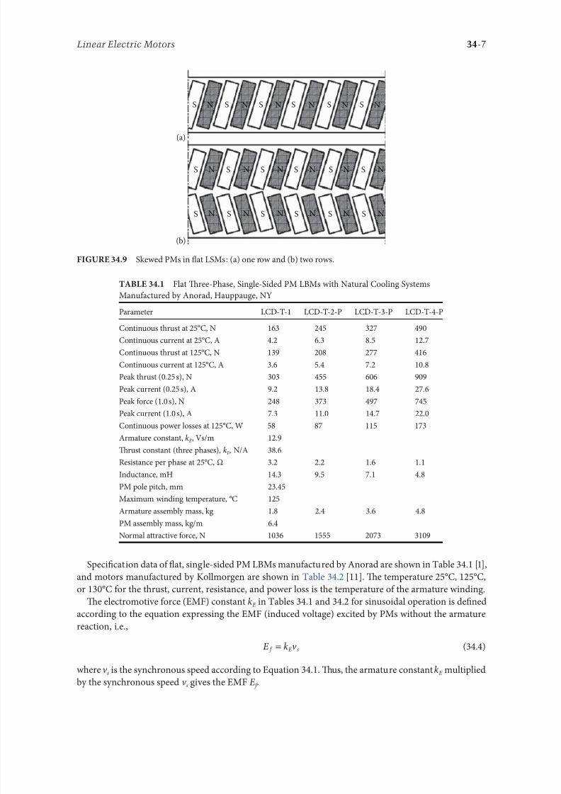
8102019 Power Handbook
httpslidepdfcomreaderfullpower-handbook 2243
34-7Linear Electric Motors
Speci1047297cation data o 1047298at single-sided PM LBMs manuactured by Anorad are shown in able 341 [1]
and motors manuactured by Kollmorgen are shown in able 342 [11] Te temperature 25degC 125degC
or 130degC or the thrust current resistance and power loss is the temperature o the armature winding
Te electromotive orce (EMF) constant kE in ables 341 and 342 or sinusoidal operation is de1047297ned
according to the equation expressing the EMF (induced voltage) excited by PMs without the armature
reaction ie
E k v E s=
(344)
where v s is the synchronous speed according to Equation 341 Tus the armature constant kE multiplied
by the synchronous speed v s gives the EMF E
S SN N N N N N
N N N N N N
N N N N N N
S S S S
S S S S S S
S
(b)
(a)
S S S S S
Skewed PMs in 1047298at LSMs (a) one row and (b) two rows
Flat Tree-Phase Single-Sided PM LBMs with Natural Cooling Systems
Manuactured by Anorad Hauppauge NY
Parameter LCD--1 LCD--2-P LCD--3-P LCD--4-P
Continuous thrust at 25degC N 163 245 327 490
Continuous current at 25degC A 42 63 85 127
Continuous thrust at 125degC N 139 208 277 416
Continuous current at 125degC A 36 54 72 108
Peak thrust (025 s) N 303 455 606 909
Peak current (025 s) A 92 138 184 276
Peak orce (10 s) N 248 373 497 745
Peak current (10 s) A 73 110 147 220Continuous power losses at 125degC W 58 87 115 173
Armature constant kE Vsm 129
Trust constant (three phases) kF NA 386
Resistance per phase at 25degC Ω 32 22 16 11
Inductance mH 143 95 71 48
PM pole pitch mm 2345
Maximum winding temperature degC 125
Armature assembly mass kg 18 24 36 48
PM assembly mass kgm 64
Normal attractive orce N 1036 1555 2073 3109
8102019 Power Handbook
httpslidepdfcomreaderfullpower-handbook 2343
34-8 Electric Power Generation Transmission and Distribution
Te thrust constant kF in ables 341 and 342 is de1047297ned according to the simpli1047297ed equation or the
developed electromagnetic thrust ie
F k I dx F a= cos Ψ
(345)
or a sinusoidally excited LSM with equal reluctances in the d - and q-axes and or the angle between the
armature current I a and the q-axis Ψ = 0deg (cos Ψ = 1) Tus the thrust constant kF times the armature
current I a gives the electromagnetic thrust developed by the LSM
Double-sided 1047298at PM LSMs consist o two external armature systems and one internal excitation sys-
tem (Figure 3410a) or one internal armature system and two external excitation systems (Figure 3410b)
In the second case a linear Grammersquos armature winding can be used
In slotless motors the primary winding is uniormly distributed on a smooth armature core or does
not have any armature core Slotless PM LSMs are detent orcendashree motors provide lower torque ripple
and at high input requency can achieve higher efficiency than slotted LSMs On the other hand larger
nonerromagnetic air gap requires more PM material and the thrust density (thrust per mass or volume)
is lower than that o slotted motors (able 343) Te input current is higher as synchronous reactances
Flat Tree-Phase Single-Sided PM LBMs with Natural Cooling Systems
Manuactured by Kollmorgen Radord VA
Parameter IC11-030 IC11-050 IC11-100 IC11-200
Continuous thrust at 130degC N 150 275 600 1260
Continuous current at 130degC A 40 44 48 50
Peak thrust N 300 500 1000 2000
Peak current A 79 79 79 79
Continuous power losses at 130degC W 64 106 210 418
Armature constant at 25degC kE Vsm 309 514 1028 2057
Trust constant (three phases) at 25degC kF NA 378 629 1259 2519
Resistance line to line at 25degC Ω 19 26 44 80
Inductance line to line mH 173 278 541 1066
Electrical time constant ms 89 105 123 134
Termal resistance winding to external
structure degCW
164 099 050 025
Maximum winding temperature degC 130
Armature assembly mass kg 20 32 62 122PM assembly mass kgm 55 76 128 269
Normal attractive orce N 1440 2430 4900 9850
(a)
N S N SN S N S
N S N SN S N S
(b)
Double-sided 1047298at PM LSMs with (a) two external armature systems and (b) one internal armature
system
8102019 Power Handbook
httpslidepdfcomreaderfullpower-handbook 2443
34-9Linear Electric Motors
in the d - and q-axes can decrease to a low undesired value due to the absence o teeth Figure 3411a
shows a single-sided 1047298at slotless motor with armature core and Figure 3411b shows a double-sided slot-
less motor with inner air-cored armature winding (moving coil motor)
able 344 contains perormance speci1047297cations o double-sided PM LBMs with inner three-phase air-
cored armature winding manuactured by rilogy Systems Corporation Webster X (Figure 3412)
N
(a) (b)
S N S N S N S
S N NS
Flat slotless PM LSMs (a) single-sided with armature core and (b) double-sided with inner air-
cored armature winding
Slotted versus Slotless LSMs
Quantity Slotted LSM Slotless LSM
Higher thrust density X
Higher efficiency in the lower speed range X
Higher efficiency in the higher speed range x
Lower input current X
Less PM material X
Lower winding cost x
Lower thrust pulsations x
Lower acoustic noise x
Flat Double-Sided PM LBMs with Inner Tree-Phase Air-Cored Series-Coil
Armature Winding Manuactured by rilogy Systems Corporation Webster X
Parameter 310-2 310-4 310-6
Continuous thrust N 1112 2091 3149
Continuous power or sinusoidal operation W 87 152 230
Peak thrust N 356 712 1068
Peak power W 900 1800 2700
Peakcontinuous current A 10028 10026 10026
Trust constant kF or sinusoidal operation NA 400 800 1200
Trust constant kF or trapezoidal operation with Hallsensors NA
351 725 1095
Resistance per phase Ω 86 172 258
Inductance plusmn05 mH 60 120 180
Heat dissipation constant or natural cooling WdegC 110 201 301
Heat dissipation constant or orced air cooling WdegC 130 240 355
Heat dissipation constant or liquid cooling WdegC 154 285 421
Number o poles 2 4 6
Coil length mm 1422 2642 3861
Coil mass kg 055 103 153
Mass o PM excitation systems kgm 1267 or 838
8102019 Power Handbook
httpslidepdfcomreaderfullpower-handbook 2543
34-10 Electric Power Generation Transmission and Distribution
By rolling a lat LSM around the axis parallel to the direction o the traveling magnetic ield
ie parallel to the direction o thrust a tubular (cylindrical) LSM can be obtained (Figure 3413) A
tubular PM LSM can also be designed as a double-sided motor or slotless motor
ubular single-sided LSMs LinMoreg with movable internal PM excitation system (slider) and stationaryexternal armature are manuactured by Sulzer Electronics AG Zurich Switzerland (able 345) All active
motor parts bearings position sensors and electronics have been integrated into a rigid metal cylinder [14]
LinMotreg is a registered trademark o Sulzer Electronics AG Zuumlrich Switzerland
(b)(a)
N S N S N S
N S N S N S
N S N S
SNN S
Single-sided slotted tubular PM LSMs (a) with external armature system and (b) with external
excitation system
Data o ubular LSMs LinMotreg Manuactured by Sulzer Electronics AG Zuumlrich Switzerland
Parameter P01 23 times 80 P01 23 times 160 P01 37 times 120 P01 37 times 240
Number o phases 2
PMs NdFeB
Maximum stroke m 0210 0340 1400 1460Maximum orce N 33 60 122 204
Maximum acceleration ms2 280 350 247 268
Maximum speed ms 24 42 40 31
Stator (armature) length m 0177 0257 0227 0347
Stator outer diameter mm 23 23 37 37
Stator mass kg 0265 0450 0740 1385
Slider diameter mm 12 12 20 20
Maximum temperature o the armature winding degC 90
Flat double-sided PM LSM with inner moving coil (Photo courtesy o rilogy Systems Webster X)
8102019 Power Handbook
httpslidepdfcomreaderfullpower-handbook 2643
34-11Linear Electric Motors
All the aorementioned PM LSMs are motors with longitudinal magnetic 1047298ux the lines o which lie
in the plane parallel to the direction o the traveling magnetic 1047297eld LSMs can also be designed as trans-
verse magnetic 1047298ux motors in which the lines o magnetic 1047298ux are perpendicular to the direction o the
traveling 1047297eld Figure 3414a shows a single-sided transverse 1047298ux LSM in which PMs are arranged in two
rows A pair o parallel PMs creates a two pole 1047298ux excitation system A double-sided con1047297guration o
transverse 1047298ux motor is possible however it is complicated and expensive (Figure 3414b)
34122 PM Motors with Passive Reaction Rail
Te drawback o PM LSMs is the large amount o PM material that must be used to design the excitation
system Normally expensive rare-earth PMs are requested I a small PM LSM uses say 10 kg o NdFeB
per 1 m o the reaction rail and 1 kg o good-quality NdFeB costs US$ 130 the cost o the reaction rail
without assembly amounts to US$ 1300 per 1 m Tis price cannot be acceptable or example in pas-
senger transportation systems
A cheaper solution is to apply the PM excitation system to the short armature that magnetizes the
long reaction rail and creates magnetic poles in it Such a linear motor is called the homopolar LSM
Te homopolar LSM as described in [517] is a double-sided AC linear motor that consists o two
polyphase armature systems connected mechanically and magnetically by a erromagnetic U-type yoke
(Figure 3415) Each armature consists o a typical slotted linear motor stack with polyphase armature
winding and PMs located between the stack and U-type yoke Since the armature and excitation systems
are combined together the armature stack is oversized as compared with a conventional steel-cored LSM
Te PMs can also be replaced by electromagnets [1719] Te variable reluctance reaction rail is passive
Te saliency is created by using erromagnetic (solid or laminated) cubes separated by a nonerromag-netic material Te reaction rail poles are magnetized by the armature PMs through the air gap Te trav-
eling magnetic 1047297eld o the polyphase armature winding and salient poles o the reaction rail produce the
thrust Such a homopolar LSM has been proposed or the propulsion o maglev trains o Swissmetro [17]
Further simpli1047297cation o the double-sided con1047297guration can be made to obtain a single-sided PM
LSM shown in Figure 3416
3413 Flux-Switching PM Linear Motors
Large gantry systems and machining centers require powerul linear motors preerably with PM-ree
reaction rail Siemens 1FN6 PM LSMs with a magnet-ree reaction rail belong to the group o the so
5
(a) (b)
5
N S
N
N
3
4
4
3
2
6
1
3
6
1
6
1
i
S
2
2
N
N
SNN
S
ransverse 1047298ux PM LSM (a) single-sided and (b) double-sided 1 armature winding 2 armature
laminated core 3 PM 4 back erromagnetic core 5 magnetic 1047298ux 6 armature current
8102019 Power Handbook
httpslidepdfcomreaderfullpower-handbook 2743
34-12 Electric Power Generation Transmission and Distribution
called 1047298ux-switching PM machines [1016] Te armature system is air cooled degree o protection IP23
class o insulation F line voltage rom 400 to 480 V rated thrust rom 235 to 2110 N maximum veloc-
ity at rated thrust rom 170 to 540 mmin (able 346) overload capacity 38 o rated thrust modular
type construction [20] Tese LSMs operate with Siemens Sinamics or Simodrive solid-state converters
and external encoders According to Siemens [20] these new LSMs produce thrust orces and velocities
equivalent to competitive classical models or light-duty machine tool machine accessory and material
handling applications
2 3 244 1
N
S
S
N
N
S
S
N
5
Single-sided PM LSM with a passive reaction rail 1 PM 2 armature winding 3 armature stack
4 yoke 5 erromagnetic reaction rail
1
1
2 343
5
Fe Fe Fe Fe
Double-sided homopolar PM LSM with passive reaction rail 1 PM 2 armature winding
3 armature stack 4 yoke 5 reaction rail
Speci1047297cations o 1FN6 PM LSMs Manuactured by Siemens Erlangen Germany
Armature Unit Rated Trust N Max Trust N
Max Speed at
Rated Trust
mmin
Max Speed at
Max Trust
mmin
Rated
Current A Max Current A
1FN6008-1LC17 235ndash350 900 263 103 17ndash26 90
1FN6008-1LC37 235ndash350 900 541 224 35ndash53 180
1FN6016-1LC30 470ndash710 1800 419 176 54ndash80 280
1FN6016-1LC17 935ndash1400 3590 263 101 70ndash105 360
1FN6024-1LC12 705ndash1060 2690 176 69 35ndash53 180
1FN6024-1LC20 705ndash1060 2690 277 114 54ndash80 280
1FN6024-1LG10 2110ndash3170 8080 172 62 105ndash160 540
1FN6024-1LG17 2110ndash3170 8080 270 102 162ndash243 840
Source Synchronous Linear Motor 1FN6 Te Electrical Gear Rack Siemens AG Industry Sector Drive echnologies
Motion Control Erlangen Germany 2008
8102019 Power Handbook
httpslidepdfcomreaderfullpower-handbook 2843
34-13Linear Electric Motors
Te magnet-ree reaction rail is easy to install and does not require the saety considerations o stan-
dard PM reaction rails Without PMs there is no problem with errous chips and other debris beingattracted to these sections Maintenance becomes a simple matter o installing a wiper or brush on the
moving part o the slide
Te 1047298ux-switching LSM comprises an armature section that is equipped with coils and PMs as well
as a nonmagnetic toothed reaction rail section (Figure 3417) Te key design innovation is an LSM in
which PMs are integrated directly into the lamination o the armature core along with the individual
windings or each phase Both magnitudes and polarities o the linkage 1047298ux in the armature winding
vary periodically along with the reaction rail movement Te magnetic 1047298ux between the armature core
and steel reaction rail is controlled by switching the three-phase armature currents according to a desig-
nated algorithm Te passive reaction rail consists o milled steel with poles (teeth) and is much simpler
to manuacture
3414 Motors with Electromagnetic Excitation
Te electromagnetic excitation system o an LSM is similar to the salient-pole rotor o a rotary
synchronous motor Figure 3418 shows a 1047298at single-sided LSM with salient erromagnetic poles and
DC 1047297eld excitation winding Te poles and pole shoes can be made o solid steel laminated steel or sin-
tered powder I the electromagnetic excitation system is integrated with the moving part the DC cur-
rent can be delivered with the aid o brushes and contact bars inductive power transer (IP) systems
linear transormers or linear brushless exciters
A AB BC C
1
2
3
4
5
v
τ2
τ1
Construction o 1047298ux-switching LSM with PM-ree reaction rail 1 laminated armature core
2 PM 3 armature coil (phase C) 4 toothed passive steel reaction rail 5 linkage magnetic 1047298ux (phase A is on)
1
3
τ τ
2
S
d d q q q
4
N
Electromagnetic excitation system o a 1047298at single-sided iron-cored LSM 1 salient pole 2 DC
excitation winding 3 erromagnetic rail (yoke) 4 armature system
8102019 Power Handbook
httpslidepdfcomreaderfullpower-handbook 2943
34-14 Electric Power Generation Transmission and Distribution
LSMs with electromagnetic excitation (wound-1047297eld reaction rail) are used in German ransrapid
maglev train (Figure 3419)
3415 Motors with Superconducting Excitation System
In large-power LSMs the electromagnets with erromagnetic core that produce the excitation 1047298ux can
be replaced by coreless SC electromagnets Since the magnetic 1047298ux density produced by the SC electro-
magnet is greater than the saturation magnetic 1047298ux density o the best laminated alloys ( Bsat asymp 24 or
cobalt alloy) there is no need to use the armature erromagnetic core An LSM with SC 1047297eld excitation
system is a totally air-cored machine (Figure 3420)
Experimental maglev trains on the Yamanashi Maglev est Line (YML) in Yamanashi Preecture(west rom okyo) Japan are driven by air-cored LSMs with SC excitation systems ( Figure 3421)
342 Linear Induction Motors
LIMs have ound the widest prospects or applications in transportation systems beginning with electri-
cal traction on small passenger or material supply cars (used at airports exhibitions electrohighways
elevators) and ending with pallet transportation waer transportation belt conveyors transportation
systems o bulk materials etc Te second important place or LIM applications is in industry ie man-
uacturing processes (machine tools hammers presses mills separators automated manuacturing systems
strip tensioners textile shuttles index tables turntables disk saws or wood sliding doors robots etc)
ransrapid 09 maglev train driven by LSMs with electromagnetic excitation (Photo courtesy oTyssen ransrapid System GmbH Munich Germany)
1
2A
B
C B
A
A
C
S SN
τ τ τ τ τ
N N
CBA
Tree-phase air-cored LSM with SC excitation system 1 armature coils 2 SC excitation coils
8102019 Power Handbook
httpslidepdfcomreaderfullpower-handbook 3043
34-15Linear Electric Motors
LIMs can also play an important part in industrial investigations and tests or example high acceleration
o model aircraf in aerodynamic tunnels high acceleration o vessels in laboratory pools propulsion o
mixers shakers and vibrators and adjusting xndashy tables and instruments Tere is also a possibility o
using LIMs in consumer electronics (sound and vision equipment knitting machines curtains) and in
offices (transportation o documents letters and cash) Te Handbook o Linear Motor Applications [21]
printed in Japan in 1986 contains about 50 examples o applications o LIMs in operation or in the pro-
cess o implementation
3421 Basic Geometries and Constructions
A LIM can be obtained by cutting in the same way either a cage rotor induction motor or a wound rotor
induction motor Te stator becomes the primary and the rotor becomes the secondary [12] Te secondary
o a LIM can be simpli1047297ed by using a solid steel core and replacing the cage (ladder) or slip-ring winding with
a high-conductivity nonerromagnetic plate (Al or Cu) Te nonerromagnetic plate is a secondary electric
circuit with distributed parameters and the erromagnetic core is a conductor both or the magnetic 1047298ux
and the electric current It does not matter rom the principle o operation point o view which part (primary
or secondary) is in motion Tus the 1047298at single-sided LIM can be obtained rom a solid rotor induction
motor (Figure 341a) and the 1047298at double-sided LIM can be obtained rom a hollow-rotor induction motor
with wound external and internal stator (Figure 341b) In a double-sided LIM the secondary erromagneticcore is not necessary since the magnetic 1047298ux excited by one o the primary windings afer passing through
the air gaps and nonerromagnetic secondary is then closed up by the core o the second primary unit
Teoretically a double-sided LIM with primary windings located on two cores in comparison with a
single-sided LIM exciting the same MMF has twice the air gap magnetic 1047298ux density Tereore the thrust
o such a motor is our times greater assuming the same dimensions I only one primary core is wound
the output parameters o a double-sided LIM are the same as those or a single-sided LIM with laminated
secondary back iron Te undamental advantage o double-sided LIMs is the elimination o the normal
attractive orce between the primary and the secondary because the secondary is usually nonerromagnetic
Flat LIMs can have primary cores consisting o an array o cores arranged in parallel at appropri-
ate distances and connected magnetically by additional yokes perpendicular to the direction o the
YML in Yamanashi Preecture (near okyo) Japan YML maglev trains use air-cored LSMs
with SC excitation system (Photo courtesy o Central Japan Railway Company and Railway echnical Research
Institute okyo Japan)
8102019 Power Handbook
httpslidepdfcomreaderfullpower-handbook 3143
34-16 Electric Power Generation Transmission and Distribution
traveling 1047297eld A magnetic circuit designed in such a way makes it possible to apply two windings in
general multiphase windings with perpendicular conductors as shown in Figure 3422 Adjusting the
current in each winding the secondary can be moved in two perpendicular directions and can be posi-
tioned at any point o the xndashy plane A 1047298at LIM with two degrees o reedom (DOFs) can be designed both
as single-sided and double-sided machines
By rolling a 1047298at single-sided or double-sided LIM around the axis parallel to the direction o the travel-
ing magnetic 1047297eld ie parallel to the direction o the thrust a tubular motor can be obtained (Figure 3423)
A tubular (cylindrical) LIM similar to a 1047298at LIM can be designed both as single-sided and double-
sided machines and can have a square or rectangular cross section as in Figure 3424 Tere are possible
Te primary o a 1047298at LIM with two DOFs
g
g
g 1
g 2
(c)
(b)
(a)
d
v
v
v
1
1
1 1
1
1
2
2
2
2
2
2
ubular LIMs (a) single-sided with an external short primary (b) single-sided with an external
short secondary and (c) double-sided with short primary 1 primary 2 secondary
8102019 Power Handbook
httpslidepdfcomreaderfullpower-handbook 3243
34-17Linear Electric Motors
con1047297gurations other than that in Figure 3423 regarding the length o the secondary with respect to thelength o the primary
All the aorementioned LIMs are motors with longitudinal magnetic 1047298ux ie the lines o magnetic
1047298ux lie in the plane parallel to the direction o the traveling magnetic 1047297eld A LIM can also be designed
in such a way as to obtain magnetic 1047298ux lines perpendicular to the direction o the traveling 1047297eld Such
motors are said to have transverse magnetic 1047298ux (Figure 3425)
Te undamental advantage o a LIM with transverse magnetic 1047298ux in comparison with a LIM with
longitudinal magnetic 1047298ux is the lower magnetizing current necessary due to the shorter magnetic 1047298ux
paths Te signi1047297cant disadvantage is lower thrust A 1047298at LIM with transverse magnetic 1047298ux usually has
a primary winding o concentrated coils located on salient poles
A 1047298at single-sided LIM with transverse 1047298ux can produce not only thrust but also electrodynamic
suspension In the design shown in Figure 3426 the secondary is suspended electrodynamically andpropelled and stabilized laterally by the primary magnetic 1047297eld [8] Te primary magnetic circuit con-
sists o E-shaped laminations assembled in two rows Te short secondary is made o light Al alloy in the
orm o a boat Te lateral sides o the boat are inclined by 60deg with respect to the active surace Such a
shape provides maximum normal repulsive orce and maximum lateral stabilization
According to their geometry the LIMs can be divided into the ollowing groups
bull With movable primary or movable secondary
bull Single sided and double sided
bull Flat and tubular
bull With short primary and short secondary
bull With longitudinal and transverse magnetic 1047298ux
1 2 3 4 1 2 3 4
ubular double-sided LIM with a square cross section 1 primary 2 secondary 3 primary coil
4 internal core
v
v
1 1
1
1
(a)
(b)
22
22
Flat LIM with transverse magnetic 1047298ux and salient poles (a) single-sided and (b) double-sided
1 primary 2 secondary
8102019 Power Handbook
httpslidepdfcomreaderfullpower-handbook 3343
34-18 Electric Power Generation Transmission and Distribution
Te linear speed o a LIM is
v s v s= minus( )1 (346)
where
s is the slip
v s is the synchronous speed according to Equation 341
Neglecting the longitudinal end effect [6] the electromagnetic thrust developed by a LIM can be
expressed in a similar way as or a rotary induction motor ie
F
m
v I
R
sdx
s
= prime( ) prime1
2
2 2
(347)
where
m1 is the number o phases o the primary winding
v s is the synchronous speed according to Equation 341
primeI 2 is the secondary current reerred to the primary system
primeR2 is the secondary resistance reerred to the primary system
s is the slip
Te secondary resistance primeR2 must include the so-called edge effect [6]
3422 Propulsion of Wheel-on-Rail Vehicles
Modern railway systems and electrical traction should meet the ollowing requirements
bull High level o automatization and computerization
bull Propulsion and braking independent o adhesion which in turn is affected 1047297rst o all by climate
and weather
bull Low level o noise sometimes below 70 dB (A)
Flat LIM with transverse magnetic 1047298ux salient poles and nonerromagnetic secondary pro-
pelled suspended and stabilized electrodynamically (From Gieras JF et al Analytical calculation o electro-
dynamic levitation orces in a special-purpose linear induction motor International Electric Machines and Drives
Conerence (IEMDCrsquo11) Niagara Falls Ontario Canada 2011 [on CD-ROM])
8102019 Power Handbook
httpslidepdfcomreaderfullpower-handbook 3443
34-19Linear Electric Motors
bull Ability to cope with high slopes at least 6 and sharp bends with radius o curvature less than 20 m
bull No pollution to natural environment and landscape
bull High reliability
Te congestion problems o big cities should be solved by creating collective transport orms that can be
implemented without affecting a highly populated city For example there are many cities in Italy where
the historical center has remained the same since the Renaissance A heavy railway might be a com-
pletely wrong solution and have a notable impact on the city planning An adequate solution might be
a light railway a people mover with transport capacity o 10000ndash20000 passengers per hour to replace
the traditional transport nets and to integrate the existing railway nets
All the requirements mentioned earlier can be met by using LIMs as propulsion machines Replacing
electrical rotary motors with linear motors in traction drives (electrical locomotives) generally does
not require new tracks but only their adjustment to linear drives Single-sided LIMs (Figure 3427a and b)
are best since the normal attractive orce o these can strengthen the adhesion o wheels and rails
Te air gap is rom 10 to 15 mm Most requently the motor car has two LIMs with short primaries
(Figure 3427a) assembled in series Te double-layer secondary consists o a solid back iron and an Al
cap and is located between the rails Cables or computer communication with the vehicle and quite
ofen collectors or electrical energy delivery to the vehicle are located along the track Tree-phaseLIMs are ed rom variable-voltage variable-requency (VVVF) voltage-source inverters A linear pro-
pulsion system o wheel-on-rail vehicles allows more 1047298exibility (Figure 3428) reducing noise on bends
and wear o the wheels and rails
Double-sided LIMs (Figure 3427c and d) have ound very limited application due to the technical
difficulty o eliminating aults caused by bends in the secondary with primary cores on either side It is
more difficult to keep a small and uniorm air gap in double-sided LIMs than that in single-sided LIMs
Te LIM-driven wheel-on-rail vehicles are built or low velocities ie less than 100 kmh and or
short routes ie less than 50 km (urban transit systems and short-distance trains) At present LIM-
driven trains operate in oronto and Vancouver BC Canada in Detroit MI (Figure 3429) okyo
(Figure 3430) and Osaka Japan and Kuala Lumpur Malaysia
(a) (b)
(c) (d)
LIM-driven wheel-on-rail cars (a) single-sided LIM with short primary mounted on the undercar-
riage (b) single-sided LIM with short secondary mounted on the undercarriage (c) double-sided LIM with short pri-
mary mounted on the undercarriage and (d) double-sided LIM with short secondary mounted on the undercarriage
8102019 Power Handbook
httpslidepdfcomreaderfullpower-handbook 3543
34-20 Electric Power Generation Transmission and Distribution
(a) (b)
Te undercarriage o a wheel-on-rail vehicle (a) rotary motor propulsion and (b) LIM propulsion
Detroit people mover driven by single-sided LIMs
oei Oedo subway line in okyo driven by single-sided LIMs
8102019 Power Handbook
httpslidepdfcomreaderfullpower-handbook 3643
34-21Linear Electric Motors
Te design data o some single-sided traction LIMs are presented in able 347 and double-sided trac-
tion LIMs in able 348
343 Variable Reluctance Motors
Te simplest construction o a variable reluctance LSM or linear reluctance motor (LRM) is that shown
in Figure 3418 with DC excitation winding being removed However the thrust o such a motor wouldbe low as the ratio o d -axis permeance to q-axis permeance is low Better perormance can be obtained
when using 1047298ux barriers [18] or steel laminations [15] o make 1047298ux barriers any nonerromagnetic
materials can be used o obtain high permeance (low reluctance) in the d -axis and low permeance in
the q-axis steel laminations should be oriented in such a way as to create high permeance or the d -axis
magnetic 1047298ux
Figure 3431a shows a variable reluctance platen with 1047298ux barriers and Figure 3431b shows how to
arrange steel laminations to obtain different reluctances in the d - and q-axes Te platen can be com-
posed o segments the length o which is equal to the pole pitchτ Each segment consists o semicircular
lamellas cut out rom electrotechnical sheet A 1047297lling or example epoxy resin is used to make the seg-
ment rigid and robust By putting the segments together a platen o any desired length can be obtained
Design Data o Single-Sided Tree-Phase LIMs or Propulsion o Vehicles
Quantity
LIM
UnitJLMDR ICS KU CIGG GEC
Pullout thrust at requency given
in the ollowing F x
125 90 35 17 07 kN
Input requency 200 400 250 400 600 Hz
Rated phase current V 1 2750 4650 1300 2000 2000 A
Number o poles 2 p 8 6 4 6 4 mdash
Number o turns per phase N 1 128 96 128 108 48 mdash
Equivalent diameter o conductor d 1 mdash 893 528 1115 81 mm
Number o parallel conductors mdash 1 mdash 19 1 mdash
Effective width o primary core Li 023 0216 029 0101 01715 m
Pole pitch τ 027 02868 030 025 020 m
Length o single end connection l e mdash 03483 mdash 02955 03685 m
Coil pitch wc 0225 01673 025 01944 01555 m
Air gap g 150 126 120 150 182 mm
Number o slots z 1( primez 1) 96(106) 72(79) 48(58) 54(61) 36(43) mdash
Width o slot b11 mdash 156 170 150 1308 mm
Width o slot opening b14 mdash 156 mdash 1044 1308 mm
Depth o slot h11 mdash 530 380 3421 6147 mm
Height o yoke h1 y mdash 436 393 7163 500 mm
Conductivity o back iron at 20degC σFe mdash 446 952 446 512 times106 Sm
Conductivity o Al cap at 20degC σ Al mdash 300 303 323 215 times106 Sm
Width o back iron w 03 024 03 0111 01715 m
Tickness o back iron hsec 190 125 250 254 474 mm
Tickness o Al cap d 50 45 50 45(25) 32 mm
Tickness o Al cap behind Fe core t ov 50 170 50 127 32 mm
Width o Al cap 030 032 040 0201 02985 m
JLMDR Japanese Linear Motor Driven Railcar Japan ICS Intermediate Capacity ransit System Canada KU
Kyushu University LIM Japan CIGG Canadian Inst o Guided Ground ransport Canada GEC General
Electric Company United States (z 1 ) is the number o hal 1047297lled slots
8102019 Power Handbook
httpslidepdfcomreaderfullpower-handbook 3743
34-22 Electric Power Generation Transmission and Distribution
344 Stepping Motors
A linear stepping motor has a concentrated armature winding wound on salient poles and PM excitation
rail or variable reluctance platen Te thrust is generated as an action o the armature magnetic 1047298ux and
PM 1047298ux (active platen) or the armature magnetic 1047298ux and salient erromagnetic poles (variable reluc-
tance platen) Stepping motors have no position eedback
Design Data o Double-Sided Tree-Phase LIMs or Propulsion
o Vehicles
Quantity
LIM
UnitGEC LIMVR
Maximum thrust at input requency F x given in the ollowing 085 1668 kN
Input requency 600 1730 Hz
Input phase current I 1 2000 20000 A
Number o poles 2 p 4 10 mdash
Number o turns per phase N 1 144 100 mdash
Diameter o conductor d 1 075 110 mm
Effective width o primary core Li 00869 0254 m
Pole pitch τ 01795 03556 m
Coil pitch wc 005 005 m
Number o slots z 1( primez 1) 36(45) 150(160) mdash
Width o slot b11 137 160 mm
Width o slot opening b14 137 mdash mm
Depth o slot h1 630 mdash mm
Height o yoke h1 y 239 mdash mm
Width o tooth c1 200 77 mm
Resultant air gap 2 g + d 381 38075 mm
Air gap g 2 times 127 2 times 111 mm
Tickness o secondary d 127 15875(hollow) mm
Effective thickness o Al secondary 127 72 mm
Width o secondary w ge03046 mdash m
Conductivity o Al cap at 20degC σ Al asymp2434 asymp240 times106 Sm
GEC General Electric Company United States LIMVR LIM Research Vehicle
Pueblo CO United States (z 1 ) is the number o hal 1047297lled slots
(a) (b)
q q d d d q d q d d
Laminations
τ τ τ τ
Epoxy resin
Variable reluctance LSMs with (a) 1047298ux barriers and (b) steel laminations
8102019 Power Handbook
httpslidepdfcomreaderfullpower-handbook 3843
8102019 Power Handbook
httpslidepdfcomreaderfullpower-handbook 3943
34-24 Electric Power Generation Transmission and Distribution
Tis value is different or ull-step and microstepping drives Te maximum startndashstop speed is the
maximum speed that can be used when starting or stopping the motor without ramping that does not
cause the motor to all out o synchronism or lose steps Te maximum speed is the maximum linear
speed that can be achieved without the motor stalling or alling out o synchronism Te maximum
load mass is the maximum allowable mass applied to the orcer against the scale that does not result in
mechanical damage Te ull-step resolution is the position increment obtained when the currents are
switched rom one winding to the next winding Tis is the typical resolution obtained with ul l-step
drives and it is strictly a unction o the motor construction Te microstepping resolution is the position
increment obtained when the ull-step resolution is divided electronically by proportioning the currents
in the two windings Tis resolution is typically 10ndash250 times smaller than the ull-step resolution [13]
HLSMs are regarded as an excellent solution to positioning systems that require a high accuracy
and rapid acceleration With a microprocessor controlled microstepping mode a smooth operation with
standard resolution o a ew hundred stepsmm can be obtained Te advantages such as high efficiencyhigh throughput mechanical simplicity high reliability precise open-loop operation and low inertia
o the system have made these kind o motors more and more attractive in such applications as actory
automation high speed positioning computer peripherals acsimile machines numerically controlled
machine tools automated medical equipment automated laboratory equipment and welding robots
Tis motor is especially suitable or machine tools printers plotters and computer-controlled material
handling in which a high positioning accuracy and repeatability are the key problems
When two or our orcers mounted at 90deg and a special grooved platen (ldquowaffle platerdquo) are used the
xndashy motion (two DOFs) in a single plane is obtained (Figure 3434)
Speci1047297cation data o the xndashy HLSMs manuactured by Normag Northern Magnetics Inc Santa
Clarita CA are given in able 3410
PM linear stepping motors (Photo courtesy o okyo Aircraf Instrument Co Ltd okyo Japan)
8102019 Power Handbook
httpslidepdfcomreaderfullpower-handbook 4043
34-25Linear Electric Motors
345 Switched Reluctance Motors
Te topology o a linear switched reluctance motor is similar to that o a stepping motor with variable
reluctance platen In addition it is equipped with position sensors Te turn-on and turn-off instant o
the input current is synchronized with the position o the moving part Te thrust is very sensitive to
the turn-on and turn-off instant
In the case o a linear stepping or linear switched reluctance motor the speed v o the moving part is
v v s sw= = τ
(348)
where
sw is the undamental switching requency in one armature phase winding
τ is the pole pitch o the reaction rail
For a rotary stepping or switched reluctance motor sw = 2 pr n where 2 pr is the number o rotor poles and
n is rotational speed in revs
A linear switched reluctance motor has a doubly salient magnetic circuit with a polyphase winding
on the armature Longitudinal and transverse 1047298ux designs are shown in Figure 3435 A linear switched
reluctance motor allows precise speed and position-controlled linear motion at low speeds and is not sub-
ject to design constraints (minimum speed limited by minimum easible pole pitch) o linear AC motors
x
y
12
3
4
1
1
2
2
HLSM with a our-unit orcer to obtain the xndashy motion 1 orcers or the x -direction 2 orcers
or the y -direction 3 platen 4 air pressure
Data o xndashy HLSMs Manuactured by Normag Northern Magnetics Inc
Santa Clarita CA
Parameter 4XY0602-2-0 4XY2002-2-0 4XY2004-2-0 4XY2504-2-0
Number o orcer units per axis 1 1 2 2
Number o phases 2 2 2(4) 2(4)Static thrust N 133 400 980 1330
Trust at 1 ms N 111 311 712 980
Normal attractive orce N 1600 4000 14400 18000
Resistance per phase Ω 29 33 16 19
Inductance per phase mH 15 40 20 23
Input phase current A 20 20 40 40
Air gap mm 002
Maximum temperature degC 110
Mass kg 32 072 20 15
Repeatability mm 000254
Resolution mm 000254
Bearing type Air
8102019 Power Handbook
httpslidepdfcomreaderfullpower-handbook 4143
34-26 Electric Power Generation Transmission and Distribution
346 Linear Positioning Stages
Linear motors are now playing a key role in advanced precision linear positioning Linear precision posi-
tioning systems can be classi1047297ed into open-loop systems with HLSMs and closed-loop servo systems
with LSMs LBMs or LIMs
A PM LSMndashdriven positioning stage is shown in Figure 3436 A stationary base is made o Al steel
ceramic or granite plate It provides a stable precise and 1047298at platorm to which all stationary position-
ing components are attached Te base o the stage is attached to the host system with the aid o mount-
ing screws
Te moving table accommodates all moving positioning components o achieve maximum accelera-
tion the mass o the moving table should be as small as possible and usually Al is used as a lightweight
material A number o mounting holes on the moving table is necessary to 1047297x the payload to the mount-
ing table
Linear bearing rails provide a precise guidance to the moving table A minimum o one bearing rail
is required Linear ball bearing or air bearings are attached to each rail
Te armature o a linear motor is astened to the moving table and reaction rail (PM excitation sys-tem) is built in the base between the rails (Figure 3436)
A linear encoder is needed to obtain precise control o position o the table velocity and acceleration
Te read head o the encoder is attached to the moving table
(a) (b)
3
3
221
1
Linear switched reluctance motor con1047297gurations (a) longitudinal 1047298ux design and (b) transverse
1047298ux design 1 armature winding 2 armature stack 3 platen
12
3
5
4
7
6
8
Linear positioning stage driven by PM LBM 1 base 2 moving table 3 armature o LBM 4 PMs
5 linear bearing 6 encoder 7 cable carrier 8 limit switch (Courtesy o Normag Santa Clarita CA)
8102019 Power Handbook
httpslidepdfcomreaderfullpower-handbook 4243
34-27Linear Electric Motors
Noncontact limit switches ixed to the base provide an overtravel protection and init ial homing
A cable carrier accommodates and routes electrical cables between the moving table and stationary
connector box 1047297xed to the base
An HLSM-driven linear precision stage is o similar construction Instead o PMs between bearing
rails it has a variable reluctance platen HLSMs usually need air bearings and in addition to the electri-
cal cables an air hose between air bearings and the compressor is requiredLinear positioning stages are used in semiconductor technology electronic assembly quality assur-
ance laser cutting optical scanning water jet cutting gantry systems (x y z stages) color printers
plotters and Cartesian coordinate robotics
References
1 Anorad Linear Motors Inormation Brochure Anorad Hauppauge New York 2007 wwwanoradcom
2 Boldea I and Nasar SA Linear Motion Electromagnetic Systems John Wiley amp Sons New York 1985
3 Boldea I and Nasar SA Linear Electric Actuators and Generators Cambridge University Press
New York 2005
4 Compumotor Digiplan Positioning Control Systems and Drives Parker Hanni1047297n CorporationRohnert Park CA 2011
5 Everes W Henneberger G Wunderlich H and Selig A A linear homopolar motor or a trans-
portation system 2nd International Symposium on Linear Drives or Industry Applications (LDIArsquo98)
okyo Japan 1998 pp 46ndash49
6 Gieras JF Linear Induction Drives Clarendon Press Oxord UK 1994
7 Gieras JF Status o linear motors in the United States International Symposium on Linear Drives
or Industry Applications (LDIArsquo03) Birmingham UK 2003 pp 169ndash176
8 Gieras JF Gientkowski Z Mews J and Splawski P Analytical calculation o electrodynamic
levitation orces in a special-purpose linear induction motor International Electric Machines and
Drives Conerence (IEMDCrsquo11) Niagara Falls Ontario Canada 2011 [on CD-ROM]
9 Gieras JF Piech ZJ and omczuk BZ Linear Synchronous Motors ransportation and Automation Systems aylor amp Francis (CRC Press) Boca Raton FL 2011
10 Hoang E Ahmed AHB and Lucidarme J Switching 1047298ux permanent magnet polyphase syn-
chronous machines 7th European Conerence on Power Electronics and Applications (EPErsquo97)
Vol 3 rondheim Norway 1977 pp 903ndash908
11 Kollmorgen Linear Motors Aim to Cut Cost o Semiconductors and Electronics Manuacture
Kollmorgen Radord VA 1997
12 Laithwaite ER A History o Linear Electric Motors Macmillan London UK 1987
13 Linear Step Motor Inormation Brochure okyo Aircraf Instrument Co Ltd okyo Japan
1998
14 LinMot Design Manual Sulzer Electronics Ltd Zuumlrich Switzerland 1999
15 Locci N and Marongiu I Modelling and testing a new linear reluctance motor InternationalConerence on Electrical Machines (ICEMrsquo92) Vol 2 Manchester UK 1992 pp 706ndash710
16 Rauch SE and Johnson LJ Design principles o 1047298ux-switch alternators AIEE rans Part III
74(12) 1261ndash1269 1955
17 Rosenmayr M Casat Glavitsch A and Stemmler H SwissmetromdashPower supply or a high-
power-propulsion system with short stator linear motors 15th International Conerence on
Magnetically Levitated Systems and Linear Drives Maglevrsquo98 Mount Fuji Yamanashi Japan 1998
pp 280ndash286
18 Sanada M Morimoto S and akeda Y Reluctance equalization design o multi 1047298ux barrier con-
struction or linear synchronous reluctance motors 2nd International Symposium on Linear Drives
or Industrial Applications (LDIArsquo98) okyo Japan 1998 pp 259ndash262
8102019 Power Handbook
httpslidepdfcomreaderfullpower-handbook 4343
34-28 Electric Power Generation Transmission and Distribution
19 Seok-Myeong J and Sang-Sub J Design and analysis o the linear homopolar synchronous motor
or integrated magnetic propulsion and suspension 2nd International Symposium on Linear Drives
or Industrial Applications (LDIArsquo98) okyo Japan 1998 pp 74ndash77
20 Synchronous Linear Motor 1FN6 Te Electrical Gear Rack Siemens AG Industry Sector Drive
echnologies Motion Control Erlangen Germany 2008
21 Yamada H Handbook o Linear Motor Applications (in Japanese) Kogyo Chosaki Publishing Cookyo Japan 1986
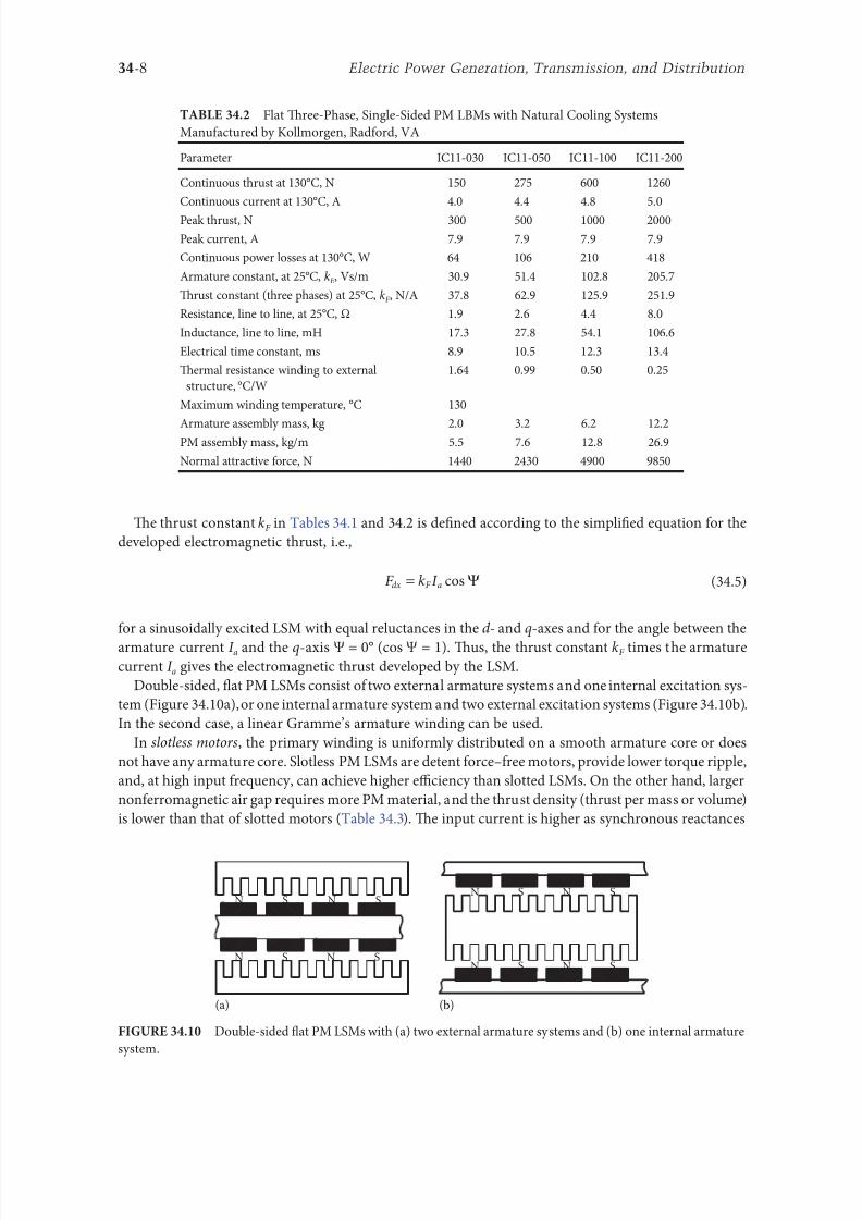
8102019 Power Handbook
httpslidepdfcomreaderfullpower-handbook 2443
34-9Linear Electric Motors
in the d - and q-axes can decrease to a low undesired value due to the absence o teeth Figure 3411a
shows a single-sided 1047298at slotless motor with armature core and Figure 3411b shows a double-sided slot-
less motor with inner air-cored armature winding (moving coil motor)
able 344 contains perormance speci1047297cations o double-sided PM LBMs with inner three-phase air-
cored armature winding manuactured by rilogy Systems Corporation Webster X (Figure 3412)
N
(a) (b)
S N S N S N S
S N NS
Flat slotless PM LSMs (a) single-sided with armature core and (b) double-sided with inner air-
cored armature winding
Slotted versus Slotless LSMs
Quantity Slotted LSM Slotless LSM
Higher thrust density X
Higher efficiency in the lower speed range X
Higher efficiency in the higher speed range x
Lower input current X
Less PM material X
Lower winding cost x
Lower thrust pulsations x
Lower acoustic noise x
Flat Double-Sided PM LBMs with Inner Tree-Phase Air-Cored Series-Coil
Armature Winding Manuactured by rilogy Systems Corporation Webster X
Parameter 310-2 310-4 310-6
Continuous thrust N 1112 2091 3149
Continuous power or sinusoidal operation W 87 152 230
Peak thrust N 356 712 1068
Peak power W 900 1800 2700
Peakcontinuous current A 10028 10026 10026
Trust constant kF or sinusoidal operation NA 400 800 1200
Trust constant kF or trapezoidal operation with Hallsensors NA
351 725 1095
Resistance per phase Ω 86 172 258
Inductance plusmn05 mH 60 120 180
Heat dissipation constant or natural cooling WdegC 110 201 301
Heat dissipation constant or orced air cooling WdegC 130 240 355
Heat dissipation constant or liquid cooling WdegC 154 285 421
Number o poles 2 4 6
Coil length mm 1422 2642 3861
Coil mass kg 055 103 153
Mass o PM excitation systems kgm 1267 or 838
8102019 Power Handbook
httpslidepdfcomreaderfullpower-handbook 2543
34-10 Electric Power Generation Transmission and Distribution
By rolling a lat LSM around the axis parallel to the direction o the traveling magnetic ield
ie parallel to the direction o thrust a tubular (cylindrical) LSM can be obtained (Figure 3413) A
tubular PM LSM can also be designed as a double-sided motor or slotless motor
ubular single-sided LSMs LinMoreg with movable internal PM excitation system (slider) and stationaryexternal armature are manuactured by Sulzer Electronics AG Zurich Switzerland (able 345) All active
motor parts bearings position sensors and electronics have been integrated into a rigid metal cylinder [14]
LinMotreg is a registered trademark o Sulzer Electronics AG Zuumlrich Switzerland
(b)(a)
N S N S N S
N S N S N S
N S N S
SNN S
Single-sided slotted tubular PM LSMs (a) with external armature system and (b) with external
excitation system
Data o ubular LSMs LinMotreg Manuactured by Sulzer Electronics AG Zuumlrich Switzerland
Parameter P01 23 times 80 P01 23 times 160 P01 37 times 120 P01 37 times 240
Number o phases 2
PMs NdFeB
Maximum stroke m 0210 0340 1400 1460Maximum orce N 33 60 122 204
Maximum acceleration ms2 280 350 247 268
Maximum speed ms 24 42 40 31
Stator (armature) length m 0177 0257 0227 0347
Stator outer diameter mm 23 23 37 37
Stator mass kg 0265 0450 0740 1385
Slider diameter mm 12 12 20 20
Maximum temperature o the armature winding degC 90
Flat double-sided PM LSM with inner moving coil (Photo courtesy o rilogy Systems Webster X)
8102019 Power Handbook
httpslidepdfcomreaderfullpower-handbook 2643
34-11Linear Electric Motors
All the aorementioned PM LSMs are motors with longitudinal magnetic 1047298ux the lines o which lie
in the plane parallel to the direction o the traveling magnetic 1047297eld LSMs can also be designed as trans-
verse magnetic 1047298ux motors in which the lines o magnetic 1047298ux are perpendicular to the direction o the
traveling 1047297eld Figure 3414a shows a single-sided transverse 1047298ux LSM in which PMs are arranged in two
rows A pair o parallel PMs creates a two pole 1047298ux excitation system A double-sided con1047297guration o
transverse 1047298ux motor is possible however it is complicated and expensive (Figure 3414b)
34122 PM Motors with Passive Reaction Rail
Te drawback o PM LSMs is the large amount o PM material that must be used to design the excitation
system Normally expensive rare-earth PMs are requested I a small PM LSM uses say 10 kg o NdFeB
per 1 m o the reaction rail and 1 kg o good-quality NdFeB costs US$ 130 the cost o the reaction rail
without assembly amounts to US$ 1300 per 1 m Tis price cannot be acceptable or example in pas-
senger transportation systems
A cheaper solution is to apply the PM excitation system to the short armature that magnetizes the
long reaction rail and creates magnetic poles in it Such a linear motor is called the homopolar LSM
Te homopolar LSM as described in [517] is a double-sided AC linear motor that consists o two
polyphase armature systems connected mechanically and magnetically by a erromagnetic U-type yoke
(Figure 3415) Each armature consists o a typical slotted linear motor stack with polyphase armature
winding and PMs located between the stack and U-type yoke Since the armature and excitation systems
are combined together the armature stack is oversized as compared with a conventional steel-cored LSM
Te PMs can also be replaced by electromagnets [1719] Te variable reluctance reaction rail is passive
Te saliency is created by using erromagnetic (solid or laminated) cubes separated by a nonerromag-netic material Te reaction rail poles are magnetized by the armature PMs through the air gap Te trav-
eling magnetic 1047297eld o the polyphase armature winding and salient poles o the reaction rail produce the
thrust Such a homopolar LSM has been proposed or the propulsion o maglev trains o Swissmetro [17]
Further simpli1047297cation o the double-sided con1047297guration can be made to obtain a single-sided PM
LSM shown in Figure 3416
3413 Flux-Switching PM Linear Motors
Large gantry systems and machining centers require powerul linear motors preerably with PM-ree
reaction rail Siemens 1FN6 PM LSMs with a magnet-ree reaction rail belong to the group o the so
5
(a) (b)
5
N S
N
N
3
4
4
3
2
6
1
3
6
1
6
1
i
S
2
2
N
N
SNN
S
ransverse 1047298ux PM LSM (a) single-sided and (b) double-sided 1 armature winding 2 armature
laminated core 3 PM 4 back erromagnetic core 5 magnetic 1047298ux 6 armature current
8102019 Power Handbook
httpslidepdfcomreaderfullpower-handbook 2743
34-12 Electric Power Generation Transmission and Distribution
called 1047298ux-switching PM machines [1016] Te armature system is air cooled degree o protection IP23
class o insulation F line voltage rom 400 to 480 V rated thrust rom 235 to 2110 N maximum veloc-
ity at rated thrust rom 170 to 540 mmin (able 346) overload capacity 38 o rated thrust modular
type construction [20] Tese LSMs operate with Siemens Sinamics or Simodrive solid-state converters
and external encoders According to Siemens [20] these new LSMs produce thrust orces and velocities
equivalent to competitive classical models or light-duty machine tool machine accessory and material
handling applications
2 3 244 1
N
S
S
N
N
S
S
N
5
Single-sided PM LSM with a passive reaction rail 1 PM 2 armature winding 3 armature stack
4 yoke 5 erromagnetic reaction rail
1
1
2 343
5
Fe Fe Fe Fe
Double-sided homopolar PM LSM with passive reaction rail 1 PM 2 armature winding
3 armature stack 4 yoke 5 reaction rail
Speci1047297cations o 1FN6 PM LSMs Manuactured by Siemens Erlangen Germany
Armature Unit Rated Trust N Max Trust N
Max Speed at
Rated Trust
mmin
Max Speed at
Max Trust
mmin
Rated
Current A Max Current A
1FN6008-1LC17 235ndash350 900 263 103 17ndash26 90
1FN6008-1LC37 235ndash350 900 541 224 35ndash53 180
1FN6016-1LC30 470ndash710 1800 419 176 54ndash80 280
1FN6016-1LC17 935ndash1400 3590 263 101 70ndash105 360
1FN6024-1LC12 705ndash1060 2690 176 69 35ndash53 180
1FN6024-1LC20 705ndash1060 2690 277 114 54ndash80 280
1FN6024-1LG10 2110ndash3170 8080 172 62 105ndash160 540
1FN6024-1LG17 2110ndash3170 8080 270 102 162ndash243 840
Source Synchronous Linear Motor 1FN6 Te Electrical Gear Rack Siemens AG Industry Sector Drive echnologies
Motion Control Erlangen Germany 2008
8102019 Power Handbook
httpslidepdfcomreaderfullpower-handbook 2843
34-13Linear Electric Motors
Te magnet-ree reaction rail is easy to install and does not require the saety considerations o stan-
dard PM reaction rails Without PMs there is no problem with errous chips and other debris beingattracted to these sections Maintenance becomes a simple matter o installing a wiper or brush on the
moving part o the slide
Te 1047298ux-switching LSM comprises an armature section that is equipped with coils and PMs as well
as a nonmagnetic toothed reaction rail section (Figure 3417) Te key design innovation is an LSM in
which PMs are integrated directly into the lamination o the armature core along with the individual
windings or each phase Both magnitudes and polarities o the linkage 1047298ux in the armature winding
vary periodically along with the reaction rail movement Te magnetic 1047298ux between the armature core
and steel reaction rail is controlled by switching the three-phase armature currents according to a desig-
nated algorithm Te passive reaction rail consists o milled steel with poles (teeth) and is much simpler
to manuacture
3414 Motors with Electromagnetic Excitation
Te electromagnetic excitation system o an LSM is similar to the salient-pole rotor o a rotary
synchronous motor Figure 3418 shows a 1047298at single-sided LSM with salient erromagnetic poles and
DC 1047297eld excitation winding Te poles and pole shoes can be made o solid steel laminated steel or sin-
tered powder I the electromagnetic excitation system is integrated with the moving part the DC cur-
rent can be delivered with the aid o brushes and contact bars inductive power transer (IP) systems
linear transormers or linear brushless exciters
A AB BC C
1
2
3
4
5
v
τ2
τ1
Construction o 1047298ux-switching LSM with PM-ree reaction rail 1 laminated armature core
2 PM 3 armature coil (phase C) 4 toothed passive steel reaction rail 5 linkage magnetic 1047298ux (phase A is on)
1
3
τ τ
2
S
d d q q q
4
N
Electromagnetic excitation system o a 1047298at single-sided iron-cored LSM 1 salient pole 2 DC
excitation winding 3 erromagnetic rail (yoke) 4 armature system
8102019 Power Handbook
httpslidepdfcomreaderfullpower-handbook 2943
34-14 Electric Power Generation Transmission and Distribution
LSMs with electromagnetic excitation (wound-1047297eld reaction rail) are used in German ransrapid
maglev train (Figure 3419)
3415 Motors with Superconducting Excitation System
In large-power LSMs the electromagnets with erromagnetic core that produce the excitation 1047298ux can
be replaced by coreless SC electromagnets Since the magnetic 1047298ux density produced by the SC electro-
magnet is greater than the saturation magnetic 1047298ux density o the best laminated alloys ( Bsat asymp 24 or
cobalt alloy) there is no need to use the armature erromagnetic core An LSM with SC 1047297eld excitation
system is a totally air-cored machine (Figure 3420)
Experimental maglev trains on the Yamanashi Maglev est Line (YML) in Yamanashi Preecture(west rom okyo) Japan are driven by air-cored LSMs with SC excitation systems ( Figure 3421)
342 Linear Induction Motors
LIMs have ound the widest prospects or applications in transportation systems beginning with electri-
cal traction on small passenger or material supply cars (used at airports exhibitions electrohighways
elevators) and ending with pallet transportation waer transportation belt conveyors transportation
systems o bulk materials etc Te second important place or LIM applications is in industry ie man-
uacturing processes (machine tools hammers presses mills separators automated manuacturing systems
strip tensioners textile shuttles index tables turntables disk saws or wood sliding doors robots etc)
ransrapid 09 maglev train driven by LSMs with electromagnetic excitation (Photo courtesy oTyssen ransrapid System GmbH Munich Germany)
1
2A
B
C B
A
A
C
S SN
τ τ τ τ τ
N N
CBA
Tree-phase air-cored LSM with SC excitation system 1 armature coils 2 SC excitation coils
8102019 Power Handbook
httpslidepdfcomreaderfullpower-handbook 3043
34-15Linear Electric Motors
LIMs can also play an important part in industrial investigations and tests or example high acceleration
o model aircraf in aerodynamic tunnels high acceleration o vessels in laboratory pools propulsion o
mixers shakers and vibrators and adjusting xndashy tables and instruments Tere is also a possibility o
using LIMs in consumer electronics (sound and vision equipment knitting machines curtains) and in
offices (transportation o documents letters and cash) Te Handbook o Linear Motor Applications [21]
printed in Japan in 1986 contains about 50 examples o applications o LIMs in operation or in the pro-
cess o implementation
3421 Basic Geometries and Constructions
A LIM can be obtained by cutting in the same way either a cage rotor induction motor or a wound rotor
induction motor Te stator becomes the primary and the rotor becomes the secondary [12] Te secondary
o a LIM can be simpli1047297ed by using a solid steel core and replacing the cage (ladder) or slip-ring winding with
a high-conductivity nonerromagnetic plate (Al or Cu) Te nonerromagnetic plate is a secondary electric
circuit with distributed parameters and the erromagnetic core is a conductor both or the magnetic 1047298ux
and the electric current It does not matter rom the principle o operation point o view which part (primary
or secondary) is in motion Tus the 1047298at single-sided LIM can be obtained rom a solid rotor induction
motor (Figure 341a) and the 1047298at double-sided LIM can be obtained rom a hollow-rotor induction motor
with wound external and internal stator (Figure 341b) In a double-sided LIM the secondary erromagneticcore is not necessary since the magnetic 1047298ux excited by one o the primary windings afer passing through
the air gaps and nonerromagnetic secondary is then closed up by the core o the second primary unit
Teoretically a double-sided LIM with primary windings located on two cores in comparison with a
single-sided LIM exciting the same MMF has twice the air gap magnetic 1047298ux density Tereore the thrust
o such a motor is our times greater assuming the same dimensions I only one primary core is wound
the output parameters o a double-sided LIM are the same as those or a single-sided LIM with laminated
secondary back iron Te undamental advantage o double-sided LIMs is the elimination o the normal
attractive orce between the primary and the secondary because the secondary is usually nonerromagnetic
Flat LIMs can have primary cores consisting o an array o cores arranged in parallel at appropri-
ate distances and connected magnetically by additional yokes perpendicular to the direction o the
YML in Yamanashi Preecture (near okyo) Japan YML maglev trains use air-cored LSMs
with SC excitation system (Photo courtesy o Central Japan Railway Company and Railway echnical Research
Institute okyo Japan)
8102019 Power Handbook
httpslidepdfcomreaderfullpower-handbook 3143
34-16 Electric Power Generation Transmission and Distribution
traveling 1047297eld A magnetic circuit designed in such a way makes it possible to apply two windings in
general multiphase windings with perpendicular conductors as shown in Figure 3422 Adjusting the
current in each winding the secondary can be moved in two perpendicular directions and can be posi-
tioned at any point o the xndashy plane A 1047298at LIM with two degrees o reedom (DOFs) can be designed both
as single-sided and double-sided machines
By rolling a 1047298at single-sided or double-sided LIM around the axis parallel to the direction o the travel-
ing magnetic 1047297eld ie parallel to the direction o the thrust a tubular motor can be obtained (Figure 3423)
A tubular (cylindrical) LIM similar to a 1047298at LIM can be designed both as single-sided and double-
sided machines and can have a square or rectangular cross section as in Figure 3424 Tere are possible
Te primary o a 1047298at LIM with two DOFs
g
g
g 1
g 2
(c)
(b)
(a)
d
v
v
v
1
1
1 1
1
1
2
2
2
2
2
2
ubular LIMs (a) single-sided with an external short primary (b) single-sided with an external
short secondary and (c) double-sided with short primary 1 primary 2 secondary
8102019 Power Handbook
httpslidepdfcomreaderfullpower-handbook 3243
34-17Linear Electric Motors
con1047297gurations other than that in Figure 3423 regarding the length o the secondary with respect to thelength o the primary
All the aorementioned LIMs are motors with longitudinal magnetic 1047298ux ie the lines o magnetic
1047298ux lie in the plane parallel to the direction o the traveling magnetic 1047297eld A LIM can also be designed
in such a way as to obtain magnetic 1047298ux lines perpendicular to the direction o the traveling 1047297eld Such
motors are said to have transverse magnetic 1047298ux (Figure 3425)
Te undamental advantage o a LIM with transverse magnetic 1047298ux in comparison with a LIM with
longitudinal magnetic 1047298ux is the lower magnetizing current necessary due to the shorter magnetic 1047298ux
paths Te signi1047297cant disadvantage is lower thrust A 1047298at LIM with transverse magnetic 1047298ux usually has
a primary winding o concentrated coils located on salient poles
A 1047298at single-sided LIM with transverse 1047298ux can produce not only thrust but also electrodynamic
suspension In the design shown in Figure 3426 the secondary is suspended electrodynamically andpropelled and stabilized laterally by the primary magnetic 1047297eld [8] Te primary magnetic circuit con-
sists o E-shaped laminations assembled in two rows Te short secondary is made o light Al alloy in the
orm o a boat Te lateral sides o the boat are inclined by 60deg with respect to the active surace Such a
shape provides maximum normal repulsive orce and maximum lateral stabilization
According to their geometry the LIMs can be divided into the ollowing groups
bull With movable primary or movable secondary
bull Single sided and double sided
bull Flat and tubular
bull With short primary and short secondary
bull With longitudinal and transverse magnetic 1047298ux
1 2 3 4 1 2 3 4
ubular double-sided LIM with a square cross section 1 primary 2 secondary 3 primary coil
4 internal core
v
v
1 1
1
1
(a)
(b)
22
22
Flat LIM with transverse magnetic 1047298ux and salient poles (a) single-sided and (b) double-sided
1 primary 2 secondary
8102019 Power Handbook
httpslidepdfcomreaderfullpower-handbook 3343
34-18 Electric Power Generation Transmission and Distribution
Te linear speed o a LIM is
v s v s= minus( )1 (346)
where
s is the slip
v s is the synchronous speed according to Equation 341
Neglecting the longitudinal end effect [6] the electromagnetic thrust developed by a LIM can be
expressed in a similar way as or a rotary induction motor ie
F
m
v I
R
sdx
s
= prime( ) prime1
2
2 2
(347)
where
m1 is the number o phases o the primary winding
v s is the synchronous speed according to Equation 341
primeI 2 is the secondary current reerred to the primary system
primeR2 is the secondary resistance reerred to the primary system
s is the slip
Te secondary resistance primeR2 must include the so-called edge effect [6]
3422 Propulsion of Wheel-on-Rail Vehicles
Modern railway systems and electrical traction should meet the ollowing requirements
bull High level o automatization and computerization
bull Propulsion and braking independent o adhesion which in turn is affected 1047297rst o all by climate
and weather
bull Low level o noise sometimes below 70 dB (A)
Flat LIM with transverse magnetic 1047298ux salient poles and nonerromagnetic secondary pro-
pelled suspended and stabilized electrodynamically (From Gieras JF et al Analytical calculation o electro-
dynamic levitation orces in a special-purpose linear induction motor International Electric Machines and Drives
Conerence (IEMDCrsquo11) Niagara Falls Ontario Canada 2011 [on CD-ROM])
8102019 Power Handbook
httpslidepdfcomreaderfullpower-handbook 3443
34-19Linear Electric Motors
bull Ability to cope with high slopes at least 6 and sharp bends with radius o curvature less than 20 m
bull No pollution to natural environment and landscape
bull High reliability
Te congestion problems o big cities should be solved by creating collective transport orms that can be
implemented without affecting a highly populated city For example there are many cities in Italy where
the historical center has remained the same since the Renaissance A heavy railway might be a com-
pletely wrong solution and have a notable impact on the city planning An adequate solution might be
a light railway a people mover with transport capacity o 10000ndash20000 passengers per hour to replace
the traditional transport nets and to integrate the existing railway nets
All the requirements mentioned earlier can be met by using LIMs as propulsion machines Replacing
electrical rotary motors with linear motors in traction drives (electrical locomotives) generally does
not require new tracks but only their adjustment to linear drives Single-sided LIMs (Figure 3427a and b)
are best since the normal attractive orce o these can strengthen the adhesion o wheels and rails
Te air gap is rom 10 to 15 mm Most requently the motor car has two LIMs with short primaries
(Figure 3427a) assembled in series Te double-layer secondary consists o a solid back iron and an Al
cap and is located between the rails Cables or computer communication with the vehicle and quite
ofen collectors or electrical energy delivery to the vehicle are located along the track Tree-phaseLIMs are ed rom variable-voltage variable-requency (VVVF) voltage-source inverters A linear pro-
pulsion system o wheel-on-rail vehicles allows more 1047298exibility (Figure 3428) reducing noise on bends
and wear o the wheels and rails
Double-sided LIMs (Figure 3427c and d) have ound very limited application due to the technical
difficulty o eliminating aults caused by bends in the secondary with primary cores on either side It is
more difficult to keep a small and uniorm air gap in double-sided LIMs than that in single-sided LIMs
Te LIM-driven wheel-on-rail vehicles are built or low velocities ie less than 100 kmh and or
short routes ie less than 50 km (urban transit systems and short-distance trains) At present LIM-
driven trains operate in oronto and Vancouver BC Canada in Detroit MI (Figure 3429) okyo
(Figure 3430) and Osaka Japan and Kuala Lumpur Malaysia
(a) (b)
(c) (d)
LIM-driven wheel-on-rail cars (a) single-sided LIM with short primary mounted on the undercar-
riage (b) single-sided LIM with short secondary mounted on the undercarriage (c) double-sided LIM with short pri-
mary mounted on the undercarriage and (d) double-sided LIM with short secondary mounted on the undercarriage
8102019 Power Handbook
httpslidepdfcomreaderfullpower-handbook 3543
34-20 Electric Power Generation Transmission and Distribution
(a) (b)
Te undercarriage o a wheel-on-rail vehicle (a) rotary motor propulsion and (b) LIM propulsion
Detroit people mover driven by single-sided LIMs
oei Oedo subway line in okyo driven by single-sided LIMs
8102019 Power Handbook
httpslidepdfcomreaderfullpower-handbook 3643
34-21Linear Electric Motors
Te design data o some single-sided traction LIMs are presented in able 347 and double-sided trac-
tion LIMs in able 348
343 Variable Reluctance Motors
Te simplest construction o a variable reluctance LSM or linear reluctance motor (LRM) is that shown
in Figure 3418 with DC excitation winding being removed However the thrust o such a motor wouldbe low as the ratio o d -axis permeance to q-axis permeance is low Better perormance can be obtained
when using 1047298ux barriers [18] or steel laminations [15] o make 1047298ux barriers any nonerromagnetic
materials can be used o obtain high permeance (low reluctance) in the d -axis and low permeance in
the q-axis steel laminations should be oriented in such a way as to create high permeance or the d -axis
magnetic 1047298ux
Figure 3431a shows a variable reluctance platen with 1047298ux barriers and Figure 3431b shows how to
arrange steel laminations to obtain different reluctances in the d - and q-axes Te platen can be com-
posed o segments the length o which is equal to the pole pitchτ Each segment consists o semicircular
lamellas cut out rom electrotechnical sheet A 1047297lling or example epoxy resin is used to make the seg-
ment rigid and robust By putting the segments together a platen o any desired length can be obtained
Design Data o Single-Sided Tree-Phase LIMs or Propulsion o Vehicles
Quantity
LIM
UnitJLMDR ICS KU CIGG GEC
Pullout thrust at requency given
in the ollowing F x
125 90 35 17 07 kN
Input requency 200 400 250 400 600 Hz
Rated phase current V 1 2750 4650 1300 2000 2000 A
Number o poles 2 p 8 6 4 6 4 mdash
Number o turns per phase N 1 128 96 128 108 48 mdash
Equivalent diameter o conductor d 1 mdash 893 528 1115 81 mm
Number o parallel conductors mdash 1 mdash 19 1 mdash
Effective width o primary core Li 023 0216 029 0101 01715 m
Pole pitch τ 027 02868 030 025 020 m
Length o single end connection l e mdash 03483 mdash 02955 03685 m
Coil pitch wc 0225 01673 025 01944 01555 m
Air gap g 150 126 120 150 182 mm
Number o slots z 1( primez 1) 96(106) 72(79) 48(58) 54(61) 36(43) mdash
Width o slot b11 mdash 156 170 150 1308 mm
Width o slot opening b14 mdash 156 mdash 1044 1308 mm
Depth o slot h11 mdash 530 380 3421 6147 mm
Height o yoke h1 y mdash 436 393 7163 500 mm
Conductivity o back iron at 20degC σFe mdash 446 952 446 512 times106 Sm
Conductivity o Al cap at 20degC σ Al mdash 300 303 323 215 times106 Sm
Width o back iron w 03 024 03 0111 01715 m
Tickness o back iron hsec 190 125 250 254 474 mm
Tickness o Al cap d 50 45 50 45(25) 32 mm
Tickness o Al cap behind Fe core t ov 50 170 50 127 32 mm
Width o Al cap 030 032 040 0201 02985 m
JLMDR Japanese Linear Motor Driven Railcar Japan ICS Intermediate Capacity ransit System Canada KU
Kyushu University LIM Japan CIGG Canadian Inst o Guided Ground ransport Canada GEC General
Electric Company United States (z 1 ) is the number o hal 1047297lled slots
8102019 Power Handbook
httpslidepdfcomreaderfullpower-handbook 3743
34-22 Electric Power Generation Transmission and Distribution
344 Stepping Motors
A linear stepping motor has a concentrated armature winding wound on salient poles and PM excitation
rail or variable reluctance platen Te thrust is generated as an action o the armature magnetic 1047298ux and
PM 1047298ux (active platen) or the armature magnetic 1047298ux and salient erromagnetic poles (variable reluc-
tance platen) Stepping motors have no position eedback
Design Data o Double-Sided Tree-Phase LIMs or Propulsion
o Vehicles
Quantity
LIM
UnitGEC LIMVR
Maximum thrust at input requency F x given in the ollowing 085 1668 kN
Input requency 600 1730 Hz
Input phase current I 1 2000 20000 A
Number o poles 2 p 4 10 mdash
Number o turns per phase N 1 144 100 mdash
Diameter o conductor d 1 075 110 mm
Effective width o primary core Li 00869 0254 m
Pole pitch τ 01795 03556 m
Coil pitch wc 005 005 m
Number o slots z 1( primez 1) 36(45) 150(160) mdash
Width o slot b11 137 160 mm
Width o slot opening b14 137 mdash mm
Depth o slot h1 630 mdash mm
Height o yoke h1 y 239 mdash mm
Width o tooth c1 200 77 mm
Resultant air gap 2 g + d 381 38075 mm
Air gap g 2 times 127 2 times 111 mm
Tickness o secondary d 127 15875(hollow) mm
Effective thickness o Al secondary 127 72 mm
Width o secondary w ge03046 mdash m
Conductivity o Al cap at 20degC σ Al asymp2434 asymp240 times106 Sm
GEC General Electric Company United States LIMVR LIM Research Vehicle
Pueblo CO United States (z 1 ) is the number o hal 1047297lled slots
(a) (b)
q q d d d q d q d d
Laminations
τ τ τ τ
Epoxy resin
Variable reluctance LSMs with (a) 1047298ux barriers and (b) steel laminations
8102019 Power Handbook
httpslidepdfcomreaderfullpower-handbook 3843
8102019 Power Handbook
httpslidepdfcomreaderfullpower-handbook 3943
34-24 Electric Power Generation Transmission and Distribution
Tis value is different or ull-step and microstepping drives Te maximum startndashstop speed is the
maximum speed that can be used when starting or stopping the motor without ramping that does not
cause the motor to all out o synchronism or lose steps Te maximum speed is the maximum linear
speed that can be achieved without the motor stalling or alling out o synchronism Te maximum
load mass is the maximum allowable mass applied to the orcer against the scale that does not result in
mechanical damage Te ull-step resolution is the position increment obtained when the currents are
switched rom one winding to the next winding Tis is the typical resolution obtained with ul l-step
drives and it is strictly a unction o the motor construction Te microstepping resolution is the position
increment obtained when the ull-step resolution is divided electronically by proportioning the currents
in the two windings Tis resolution is typically 10ndash250 times smaller than the ull-step resolution [13]
HLSMs are regarded as an excellent solution to positioning systems that require a high accuracy
and rapid acceleration With a microprocessor controlled microstepping mode a smooth operation with
standard resolution o a ew hundred stepsmm can be obtained Te advantages such as high efficiencyhigh throughput mechanical simplicity high reliability precise open-loop operation and low inertia
o the system have made these kind o motors more and more attractive in such applications as actory
automation high speed positioning computer peripherals acsimile machines numerically controlled
machine tools automated medical equipment automated laboratory equipment and welding robots
Tis motor is especially suitable or machine tools printers plotters and computer-controlled material
handling in which a high positioning accuracy and repeatability are the key problems
When two or our orcers mounted at 90deg and a special grooved platen (ldquowaffle platerdquo) are used the
xndashy motion (two DOFs) in a single plane is obtained (Figure 3434)
Speci1047297cation data o the xndashy HLSMs manuactured by Normag Northern Magnetics Inc Santa
Clarita CA are given in able 3410
PM linear stepping motors (Photo courtesy o okyo Aircraf Instrument Co Ltd okyo Japan)
8102019 Power Handbook
httpslidepdfcomreaderfullpower-handbook 4043
34-25Linear Electric Motors
345 Switched Reluctance Motors
Te topology o a linear switched reluctance motor is similar to that o a stepping motor with variable
reluctance platen In addition it is equipped with position sensors Te turn-on and turn-off instant o
the input current is synchronized with the position o the moving part Te thrust is very sensitive to
the turn-on and turn-off instant
In the case o a linear stepping or linear switched reluctance motor the speed v o the moving part is
v v s sw= = τ
(348)
where
sw is the undamental switching requency in one armature phase winding
τ is the pole pitch o the reaction rail
For a rotary stepping or switched reluctance motor sw = 2 pr n where 2 pr is the number o rotor poles and
n is rotational speed in revs
A linear switched reluctance motor has a doubly salient magnetic circuit with a polyphase winding
on the armature Longitudinal and transverse 1047298ux designs are shown in Figure 3435 A linear switched
reluctance motor allows precise speed and position-controlled linear motion at low speeds and is not sub-
ject to design constraints (minimum speed limited by minimum easible pole pitch) o linear AC motors
x
y
12
3
4
1
1
2
2
HLSM with a our-unit orcer to obtain the xndashy motion 1 orcers or the x -direction 2 orcers
or the y -direction 3 platen 4 air pressure
Data o xndashy HLSMs Manuactured by Normag Northern Magnetics Inc
Santa Clarita CA
Parameter 4XY0602-2-0 4XY2002-2-0 4XY2004-2-0 4XY2504-2-0
Number o orcer units per axis 1 1 2 2
Number o phases 2 2 2(4) 2(4)Static thrust N 133 400 980 1330
Trust at 1 ms N 111 311 712 980
Normal attractive orce N 1600 4000 14400 18000
Resistance per phase Ω 29 33 16 19
Inductance per phase mH 15 40 20 23
Input phase current A 20 20 40 40
Air gap mm 002
Maximum temperature degC 110
Mass kg 32 072 20 15
Repeatability mm 000254
Resolution mm 000254
Bearing type Air
8102019 Power Handbook
httpslidepdfcomreaderfullpower-handbook 4143
34-26 Electric Power Generation Transmission and Distribution
346 Linear Positioning Stages
Linear motors are now playing a key role in advanced precision linear positioning Linear precision posi-
tioning systems can be classi1047297ed into open-loop systems with HLSMs and closed-loop servo systems
with LSMs LBMs or LIMs
A PM LSMndashdriven positioning stage is shown in Figure 3436 A stationary base is made o Al steel
ceramic or granite plate It provides a stable precise and 1047298at platorm to which all stationary position-
ing components are attached Te base o the stage is attached to the host system with the aid o mount-
ing screws
Te moving table accommodates all moving positioning components o achieve maximum accelera-
tion the mass o the moving table should be as small as possible and usually Al is used as a lightweight
material A number o mounting holes on the moving table is necessary to 1047297x the payload to the mount-
ing table
Linear bearing rails provide a precise guidance to the moving table A minimum o one bearing rail
is required Linear ball bearing or air bearings are attached to each rail
Te armature o a linear motor is astened to the moving table and reaction rail (PM excitation sys-tem) is built in the base between the rails (Figure 3436)
A linear encoder is needed to obtain precise control o position o the table velocity and acceleration
Te read head o the encoder is attached to the moving table
(a) (b)
3
3
221
1
Linear switched reluctance motor con1047297gurations (a) longitudinal 1047298ux design and (b) transverse
1047298ux design 1 armature winding 2 armature stack 3 platen
12
3
5
4
7
6
8
Linear positioning stage driven by PM LBM 1 base 2 moving table 3 armature o LBM 4 PMs
5 linear bearing 6 encoder 7 cable carrier 8 limit switch (Courtesy o Normag Santa Clarita CA)
8102019 Power Handbook
httpslidepdfcomreaderfullpower-handbook 4243
34-27Linear Electric Motors
Noncontact limit switches ixed to the base provide an overtravel protection and init ial homing
A cable carrier accommodates and routes electrical cables between the moving table and stationary
connector box 1047297xed to the base
An HLSM-driven linear precision stage is o similar construction Instead o PMs between bearing
rails it has a variable reluctance platen HLSMs usually need air bearings and in addition to the electri-
cal cables an air hose between air bearings and the compressor is requiredLinear positioning stages are used in semiconductor technology electronic assembly quality assur-
ance laser cutting optical scanning water jet cutting gantry systems (x y z stages) color printers
plotters and Cartesian coordinate robotics
References
1 Anorad Linear Motors Inormation Brochure Anorad Hauppauge New York 2007 wwwanoradcom
2 Boldea I and Nasar SA Linear Motion Electromagnetic Systems John Wiley amp Sons New York 1985
3 Boldea I and Nasar SA Linear Electric Actuators and Generators Cambridge University Press
New York 2005
4 Compumotor Digiplan Positioning Control Systems and Drives Parker Hanni1047297n CorporationRohnert Park CA 2011
5 Everes W Henneberger G Wunderlich H and Selig A A linear homopolar motor or a trans-
portation system 2nd International Symposium on Linear Drives or Industry Applications (LDIArsquo98)
okyo Japan 1998 pp 46ndash49
6 Gieras JF Linear Induction Drives Clarendon Press Oxord UK 1994
7 Gieras JF Status o linear motors in the United States International Symposium on Linear Drives
or Industry Applications (LDIArsquo03) Birmingham UK 2003 pp 169ndash176
8 Gieras JF Gientkowski Z Mews J and Splawski P Analytical calculation o electrodynamic
levitation orces in a special-purpose linear induction motor International Electric Machines and
Drives Conerence (IEMDCrsquo11) Niagara Falls Ontario Canada 2011 [on CD-ROM]
9 Gieras JF Piech ZJ and omczuk BZ Linear Synchronous Motors ransportation and Automation Systems aylor amp Francis (CRC Press) Boca Raton FL 2011
10 Hoang E Ahmed AHB and Lucidarme J Switching 1047298ux permanent magnet polyphase syn-
chronous machines 7th European Conerence on Power Electronics and Applications (EPErsquo97)
Vol 3 rondheim Norway 1977 pp 903ndash908
11 Kollmorgen Linear Motors Aim to Cut Cost o Semiconductors and Electronics Manuacture
Kollmorgen Radord VA 1997
12 Laithwaite ER A History o Linear Electric Motors Macmillan London UK 1987
13 Linear Step Motor Inormation Brochure okyo Aircraf Instrument Co Ltd okyo Japan
1998
14 LinMot Design Manual Sulzer Electronics Ltd Zuumlrich Switzerland 1999
15 Locci N and Marongiu I Modelling and testing a new linear reluctance motor InternationalConerence on Electrical Machines (ICEMrsquo92) Vol 2 Manchester UK 1992 pp 706ndash710
16 Rauch SE and Johnson LJ Design principles o 1047298ux-switch alternators AIEE rans Part III
74(12) 1261ndash1269 1955
17 Rosenmayr M Casat Glavitsch A and Stemmler H SwissmetromdashPower supply or a high-
power-propulsion system with short stator linear motors 15th International Conerence on
Magnetically Levitated Systems and Linear Drives Maglevrsquo98 Mount Fuji Yamanashi Japan 1998
pp 280ndash286
18 Sanada M Morimoto S and akeda Y Reluctance equalization design o multi 1047298ux barrier con-
struction or linear synchronous reluctance motors 2nd International Symposium on Linear Drives
or Industrial Applications (LDIArsquo98) okyo Japan 1998 pp 259ndash262
8102019 Power Handbook
httpslidepdfcomreaderfullpower-handbook 4343
34-28 Electric Power Generation Transmission and Distribution
19 Seok-Myeong J and Sang-Sub J Design and analysis o the linear homopolar synchronous motor
or integrated magnetic propulsion and suspension 2nd International Symposium on Linear Drives
or Industrial Applications (LDIArsquo98) okyo Japan 1998 pp 74ndash77
20 Synchronous Linear Motor 1FN6 Te Electrical Gear Rack Siemens AG Industry Sector Drive
echnologies Motion Control Erlangen Germany 2008
21 Yamada H Handbook o Linear Motor Applications (in Japanese) Kogyo Chosaki Publishing Cookyo Japan 1986
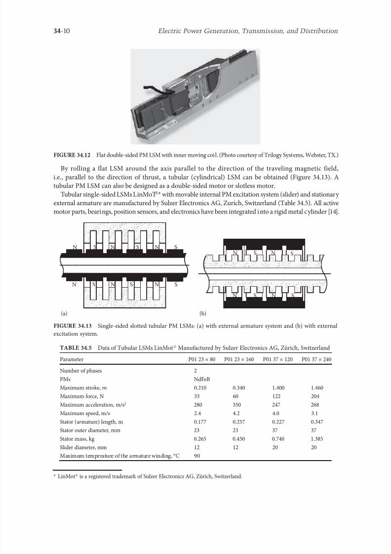
8102019 Power Handbook
httpslidepdfcomreaderfullpower-handbook 2543
34-10 Electric Power Generation Transmission and Distribution
By rolling a lat LSM around the axis parallel to the direction o the traveling magnetic ield
ie parallel to the direction o thrust a tubular (cylindrical) LSM can be obtained (Figure 3413) A
tubular PM LSM can also be designed as a double-sided motor or slotless motor
ubular single-sided LSMs LinMoreg with movable internal PM excitation system (slider) and stationaryexternal armature are manuactured by Sulzer Electronics AG Zurich Switzerland (able 345) All active
motor parts bearings position sensors and electronics have been integrated into a rigid metal cylinder [14]
LinMotreg is a registered trademark o Sulzer Electronics AG Zuumlrich Switzerland
(b)(a)
N S N S N S
N S N S N S
N S N S
SNN S
Single-sided slotted tubular PM LSMs (a) with external armature system and (b) with external
excitation system
Data o ubular LSMs LinMotreg Manuactured by Sulzer Electronics AG Zuumlrich Switzerland
Parameter P01 23 times 80 P01 23 times 160 P01 37 times 120 P01 37 times 240
Number o phases 2
PMs NdFeB
Maximum stroke m 0210 0340 1400 1460Maximum orce N 33 60 122 204
Maximum acceleration ms2 280 350 247 268
Maximum speed ms 24 42 40 31
Stator (armature) length m 0177 0257 0227 0347
Stator outer diameter mm 23 23 37 37
Stator mass kg 0265 0450 0740 1385
Slider diameter mm 12 12 20 20
Maximum temperature o the armature winding degC 90
Flat double-sided PM LSM with inner moving coil (Photo courtesy o rilogy Systems Webster X)
8102019 Power Handbook
httpslidepdfcomreaderfullpower-handbook 2643
34-11Linear Electric Motors
All the aorementioned PM LSMs are motors with longitudinal magnetic 1047298ux the lines o which lie
in the plane parallel to the direction o the traveling magnetic 1047297eld LSMs can also be designed as trans-
verse magnetic 1047298ux motors in which the lines o magnetic 1047298ux are perpendicular to the direction o the
traveling 1047297eld Figure 3414a shows a single-sided transverse 1047298ux LSM in which PMs are arranged in two
rows A pair o parallel PMs creates a two pole 1047298ux excitation system A double-sided con1047297guration o
transverse 1047298ux motor is possible however it is complicated and expensive (Figure 3414b)
34122 PM Motors with Passive Reaction Rail
Te drawback o PM LSMs is the large amount o PM material that must be used to design the excitation
system Normally expensive rare-earth PMs are requested I a small PM LSM uses say 10 kg o NdFeB
per 1 m o the reaction rail and 1 kg o good-quality NdFeB costs US$ 130 the cost o the reaction rail
without assembly amounts to US$ 1300 per 1 m Tis price cannot be acceptable or example in pas-
senger transportation systems
A cheaper solution is to apply the PM excitation system to the short armature that magnetizes the
long reaction rail and creates magnetic poles in it Such a linear motor is called the homopolar LSM
Te homopolar LSM as described in [517] is a double-sided AC linear motor that consists o two
polyphase armature systems connected mechanically and magnetically by a erromagnetic U-type yoke
(Figure 3415) Each armature consists o a typical slotted linear motor stack with polyphase armature
winding and PMs located between the stack and U-type yoke Since the armature and excitation systems
are combined together the armature stack is oversized as compared with a conventional steel-cored LSM
Te PMs can also be replaced by electromagnets [1719] Te variable reluctance reaction rail is passive
Te saliency is created by using erromagnetic (solid or laminated) cubes separated by a nonerromag-netic material Te reaction rail poles are magnetized by the armature PMs through the air gap Te trav-
eling magnetic 1047297eld o the polyphase armature winding and salient poles o the reaction rail produce the
thrust Such a homopolar LSM has been proposed or the propulsion o maglev trains o Swissmetro [17]
Further simpli1047297cation o the double-sided con1047297guration can be made to obtain a single-sided PM
LSM shown in Figure 3416
3413 Flux-Switching PM Linear Motors
Large gantry systems and machining centers require powerul linear motors preerably with PM-ree
reaction rail Siemens 1FN6 PM LSMs with a magnet-ree reaction rail belong to the group o the so
5
(a) (b)
5
N S
N
N
3
4
4
3
2
6
1
3
6
1
6
1
i
S
2
2
N
N
SNN
S
ransverse 1047298ux PM LSM (a) single-sided and (b) double-sided 1 armature winding 2 armature
laminated core 3 PM 4 back erromagnetic core 5 magnetic 1047298ux 6 armature current
8102019 Power Handbook
httpslidepdfcomreaderfullpower-handbook 2743
34-12 Electric Power Generation Transmission and Distribution
called 1047298ux-switching PM machines [1016] Te armature system is air cooled degree o protection IP23
class o insulation F line voltage rom 400 to 480 V rated thrust rom 235 to 2110 N maximum veloc-
ity at rated thrust rom 170 to 540 mmin (able 346) overload capacity 38 o rated thrust modular
type construction [20] Tese LSMs operate with Siemens Sinamics or Simodrive solid-state converters
and external encoders According to Siemens [20] these new LSMs produce thrust orces and velocities
equivalent to competitive classical models or light-duty machine tool machine accessory and material
handling applications
2 3 244 1
N
S
S
N
N
S
S
N
5
Single-sided PM LSM with a passive reaction rail 1 PM 2 armature winding 3 armature stack
4 yoke 5 erromagnetic reaction rail
1
1
2 343
5
Fe Fe Fe Fe
Double-sided homopolar PM LSM with passive reaction rail 1 PM 2 armature winding
3 armature stack 4 yoke 5 reaction rail
Speci1047297cations o 1FN6 PM LSMs Manuactured by Siemens Erlangen Germany
Armature Unit Rated Trust N Max Trust N
Max Speed at
Rated Trust
mmin
Max Speed at
Max Trust
mmin
Rated
Current A Max Current A
1FN6008-1LC17 235ndash350 900 263 103 17ndash26 90
1FN6008-1LC37 235ndash350 900 541 224 35ndash53 180
1FN6016-1LC30 470ndash710 1800 419 176 54ndash80 280
1FN6016-1LC17 935ndash1400 3590 263 101 70ndash105 360
1FN6024-1LC12 705ndash1060 2690 176 69 35ndash53 180
1FN6024-1LC20 705ndash1060 2690 277 114 54ndash80 280
1FN6024-1LG10 2110ndash3170 8080 172 62 105ndash160 540
1FN6024-1LG17 2110ndash3170 8080 270 102 162ndash243 840
Source Synchronous Linear Motor 1FN6 Te Electrical Gear Rack Siemens AG Industry Sector Drive echnologies
Motion Control Erlangen Germany 2008
8102019 Power Handbook
httpslidepdfcomreaderfullpower-handbook 2843
34-13Linear Electric Motors
Te magnet-ree reaction rail is easy to install and does not require the saety considerations o stan-
dard PM reaction rails Without PMs there is no problem with errous chips and other debris beingattracted to these sections Maintenance becomes a simple matter o installing a wiper or brush on the
moving part o the slide
Te 1047298ux-switching LSM comprises an armature section that is equipped with coils and PMs as well
as a nonmagnetic toothed reaction rail section (Figure 3417) Te key design innovation is an LSM in
which PMs are integrated directly into the lamination o the armature core along with the individual
windings or each phase Both magnitudes and polarities o the linkage 1047298ux in the armature winding
vary periodically along with the reaction rail movement Te magnetic 1047298ux between the armature core
and steel reaction rail is controlled by switching the three-phase armature currents according to a desig-
nated algorithm Te passive reaction rail consists o milled steel with poles (teeth) and is much simpler
to manuacture
3414 Motors with Electromagnetic Excitation
Te electromagnetic excitation system o an LSM is similar to the salient-pole rotor o a rotary
synchronous motor Figure 3418 shows a 1047298at single-sided LSM with salient erromagnetic poles and
DC 1047297eld excitation winding Te poles and pole shoes can be made o solid steel laminated steel or sin-
tered powder I the electromagnetic excitation system is integrated with the moving part the DC cur-
rent can be delivered with the aid o brushes and contact bars inductive power transer (IP) systems
linear transormers or linear brushless exciters
A AB BC C
1
2
3
4
5
v
τ2
τ1
Construction o 1047298ux-switching LSM with PM-ree reaction rail 1 laminated armature core
2 PM 3 armature coil (phase C) 4 toothed passive steel reaction rail 5 linkage magnetic 1047298ux (phase A is on)
1
3
τ τ
2
S
d d q q q
4
N
Electromagnetic excitation system o a 1047298at single-sided iron-cored LSM 1 salient pole 2 DC
excitation winding 3 erromagnetic rail (yoke) 4 armature system
8102019 Power Handbook
httpslidepdfcomreaderfullpower-handbook 2943
34-14 Electric Power Generation Transmission and Distribution
LSMs with electromagnetic excitation (wound-1047297eld reaction rail) are used in German ransrapid
maglev train (Figure 3419)
3415 Motors with Superconducting Excitation System
In large-power LSMs the electromagnets with erromagnetic core that produce the excitation 1047298ux can
be replaced by coreless SC electromagnets Since the magnetic 1047298ux density produced by the SC electro-
magnet is greater than the saturation magnetic 1047298ux density o the best laminated alloys ( Bsat asymp 24 or
cobalt alloy) there is no need to use the armature erromagnetic core An LSM with SC 1047297eld excitation
system is a totally air-cored machine (Figure 3420)
Experimental maglev trains on the Yamanashi Maglev est Line (YML) in Yamanashi Preecture(west rom okyo) Japan are driven by air-cored LSMs with SC excitation systems ( Figure 3421)
342 Linear Induction Motors
LIMs have ound the widest prospects or applications in transportation systems beginning with electri-
cal traction on small passenger or material supply cars (used at airports exhibitions electrohighways
elevators) and ending with pallet transportation waer transportation belt conveyors transportation
systems o bulk materials etc Te second important place or LIM applications is in industry ie man-
uacturing processes (machine tools hammers presses mills separators automated manuacturing systems
strip tensioners textile shuttles index tables turntables disk saws or wood sliding doors robots etc)
ransrapid 09 maglev train driven by LSMs with electromagnetic excitation (Photo courtesy oTyssen ransrapid System GmbH Munich Germany)
1
2A
B
C B
A
A
C
S SN
τ τ τ τ τ
N N
CBA
Tree-phase air-cored LSM with SC excitation system 1 armature coils 2 SC excitation coils
8102019 Power Handbook
httpslidepdfcomreaderfullpower-handbook 3043
34-15Linear Electric Motors
LIMs can also play an important part in industrial investigations and tests or example high acceleration
o model aircraf in aerodynamic tunnels high acceleration o vessels in laboratory pools propulsion o
mixers shakers and vibrators and adjusting xndashy tables and instruments Tere is also a possibility o
using LIMs in consumer electronics (sound and vision equipment knitting machines curtains) and in
offices (transportation o documents letters and cash) Te Handbook o Linear Motor Applications [21]
printed in Japan in 1986 contains about 50 examples o applications o LIMs in operation or in the pro-
cess o implementation
3421 Basic Geometries and Constructions
A LIM can be obtained by cutting in the same way either a cage rotor induction motor or a wound rotor
induction motor Te stator becomes the primary and the rotor becomes the secondary [12] Te secondary
o a LIM can be simpli1047297ed by using a solid steel core and replacing the cage (ladder) or slip-ring winding with
a high-conductivity nonerromagnetic plate (Al or Cu) Te nonerromagnetic plate is a secondary electric
circuit with distributed parameters and the erromagnetic core is a conductor both or the magnetic 1047298ux
and the electric current It does not matter rom the principle o operation point o view which part (primary
or secondary) is in motion Tus the 1047298at single-sided LIM can be obtained rom a solid rotor induction
motor (Figure 341a) and the 1047298at double-sided LIM can be obtained rom a hollow-rotor induction motor
with wound external and internal stator (Figure 341b) In a double-sided LIM the secondary erromagneticcore is not necessary since the magnetic 1047298ux excited by one o the primary windings afer passing through
the air gaps and nonerromagnetic secondary is then closed up by the core o the second primary unit
Teoretically a double-sided LIM with primary windings located on two cores in comparison with a
single-sided LIM exciting the same MMF has twice the air gap magnetic 1047298ux density Tereore the thrust
o such a motor is our times greater assuming the same dimensions I only one primary core is wound
the output parameters o a double-sided LIM are the same as those or a single-sided LIM with laminated
secondary back iron Te undamental advantage o double-sided LIMs is the elimination o the normal
attractive orce between the primary and the secondary because the secondary is usually nonerromagnetic
Flat LIMs can have primary cores consisting o an array o cores arranged in parallel at appropri-
ate distances and connected magnetically by additional yokes perpendicular to the direction o the
YML in Yamanashi Preecture (near okyo) Japan YML maglev trains use air-cored LSMs
with SC excitation system (Photo courtesy o Central Japan Railway Company and Railway echnical Research
Institute okyo Japan)
8102019 Power Handbook
httpslidepdfcomreaderfullpower-handbook 3143
34-16 Electric Power Generation Transmission and Distribution
traveling 1047297eld A magnetic circuit designed in such a way makes it possible to apply two windings in
general multiphase windings with perpendicular conductors as shown in Figure 3422 Adjusting the
current in each winding the secondary can be moved in two perpendicular directions and can be posi-
tioned at any point o the xndashy plane A 1047298at LIM with two degrees o reedom (DOFs) can be designed both
as single-sided and double-sided machines
By rolling a 1047298at single-sided or double-sided LIM around the axis parallel to the direction o the travel-
ing magnetic 1047297eld ie parallel to the direction o the thrust a tubular motor can be obtained (Figure 3423)
A tubular (cylindrical) LIM similar to a 1047298at LIM can be designed both as single-sided and double-
sided machines and can have a square or rectangular cross section as in Figure 3424 Tere are possible
Te primary o a 1047298at LIM with two DOFs
g
g
g 1
g 2
(c)
(b)
(a)
d
v
v
v
1
1
1 1
1
1
2
2
2
2
2
2
ubular LIMs (a) single-sided with an external short primary (b) single-sided with an external
short secondary and (c) double-sided with short primary 1 primary 2 secondary
8102019 Power Handbook
httpslidepdfcomreaderfullpower-handbook 3243
34-17Linear Electric Motors
con1047297gurations other than that in Figure 3423 regarding the length o the secondary with respect to thelength o the primary
All the aorementioned LIMs are motors with longitudinal magnetic 1047298ux ie the lines o magnetic
1047298ux lie in the plane parallel to the direction o the traveling magnetic 1047297eld A LIM can also be designed
in such a way as to obtain magnetic 1047298ux lines perpendicular to the direction o the traveling 1047297eld Such
motors are said to have transverse magnetic 1047298ux (Figure 3425)
Te undamental advantage o a LIM with transverse magnetic 1047298ux in comparison with a LIM with
longitudinal magnetic 1047298ux is the lower magnetizing current necessary due to the shorter magnetic 1047298ux
paths Te signi1047297cant disadvantage is lower thrust A 1047298at LIM with transverse magnetic 1047298ux usually has
a primary winding o concentrated coils located on salient poles
A 1047298at single-sided LIM with transverse 1047298ux can produce not only thrust but also electrodynamic
suspension In the design shown in Figure 3426 the secondary is suspended electrodynamically andpropelled and stabilized laterally by the primary magnetic 1047297eld [8] Te primary magnetic circuit con-
sists o E-shaped laminations assembled in two rows Te short secondary is made o light Al alloy in the
orm o a boat Te lateral sides o the boat are inclined by 60deg with respect to the active surace Such a
shape provides maximum normal repulsive orce and maximum lateral stabilization
According to their geometry the LIMs can be divided into the ollowing groups
bull With movable primary or movable secondary
bull Single sided and double sided
bull Flat and tubular
bull With short primary and short secondary
bull With longitudinal and transverse magnetic 1047298ux
1 2 3 4 1 2 3 4
ubular double-sided LIM with a square cross section 1 primary 2 secondary 3 primary coil
4 internal core
v
v
1 1
1
1
(a)
(b)
22
22
Flat LIM with transverse magnetic 1047298ux and salient poles (a) single-sided and (b) double-sided
1 primary 2 secondary
8102019 Power Handbook
httpslidepdfcomreaderfullpower-handbook 3343
34-18 Electric Power Generation Transmission and Distribution
Te linear speed o a LIM is
v s v s= minus( )1 (346)
where
s is the slip
v s is the synchronous speed according to Equation 341
Neglecting the longitudinal end effect [6] the electromagnetic thrust developed by a LIM can be
expressed in a similar way as or a rotary induction motor ie
F
m
v I
R
sdx
s
= prime( ) prime1
2
2 2
(347)
where
m1 is the number o phases o the primary winding
v s is the synchronous speed according to Equation 341
primeI 2 is the secondary current reerred to the primary system
primeR2 is the secondary resistance reerred to the primary system
s is the slip
Te secondary resistance primeR2 must include the so-called edge effect [6]
3422 Propulsion of Wheel-on-Rail Vehicles
Modern railway systems and electrical traction should meet the ollowing requirements
bull High level o automatization and computerization
bull Propulsion and braking independent o adhesion which in turn is affected 1047297rst o all by climate
and weather
bull Low level o noise sometimes below 70 dB (A)
Flat LIM with transverse magnetic 1047298ux salient poles and nonerromagnetic secondary pro-
pelled suspended and stabilized electrodynamically (From Gieras JF et al Analytical calculation o electro-
dynamic levitation orces in a special-purpose linear induction motor International Electric Machines and Drives
Conerence (IEMDCrsquo11) Niagara Falls Ontario Canada 2011 [on CD-ROM])
8102019 Power Handbook
httpslidepdfcomreaderfullpower-handbook 3443
34-19Linear Electric Motors
bull Ability to cope with high slopes at least 6 and sharp bends with radius o curvature less than 20 m
bull No pollution to natural environment and landscape
bull High reliability
Te congestion problems o big cities should be solved by creating collective transport orms that can be
implemented without affecting a highly populated city For example there are many cities in Italy where
the historical center has remained the same since the Renaissance A heavy railway might be a com-
pletely wrong solution and have a notable impact on the city planning An adequate solution might be
a light railway a people mover with transport capacity o 10000ndash20000 passengers per hour to replace
the traditional transport nets and to integrate the existing railway nets
All the requirements mentioned earlier can be met by using LIMs as propulsion machines Replacing
electrical rotary motors with linear motors in traction drives (electrical locomotives) generally does
not require new tracks but only their adjustment to linear drives Single-sided LIMs (Figure 3427a and b)
are best since the normal attractive orce o these can strengthen the adhesion o wheels and rails
Te air gap is rom 10 to 15 mm Most requently the motor car has two LIMs with short primaries
(Figure 3427a) assembled in series Te double-layer secondary consists o a solid back iron and an Al
cap and is located between the rails Cables or computer communication with the vehicle and quite
ofen collectors or electrical energy delivery to the vehicle are located along the track Tree-phaseLIMs are ed rom variable-voltage variable-requency (VVVF) voltage-source inverters A linear pro-
pulsion system o wheel-on-rail vehicles allows more 1047298exibility (Figure 3428) reducing noise on bends
and wear o the wheels and rails
Double-sided LIMs (Figure 3427c and d) have ound very limited application due to the technical
difficulty o eliminating aults caused by bends in the secondary with primary cores on either side It is
more difficult to keep a small and uniorm air gap in double-sided LIMs than that in single-sided LIMs
Te LIM-driven wheel-on-rail vehicles are built or low velocities ie less than 100 kmh and or
short routes ie less than 50 km (urban transit systems and short-distance trains) At present LIM-
driven trains operate in oronto and Vancouver BC Canada in Detroit MI (Figure 3429) okyo
(Figure 3430) and Osaka Japan and Kuala Lumpur Malaysia
(a) (b)
(c) (d)
LIM-driven wheel-on-rail cars (a) single-sided LIM with short primary mounted on the undercar-
riage (b) single-sided LIM with short secondary mounted on the undercarriage (c) double-sided LIM with short pri-
mary mounted on the undercarriage and (d) double-sided LIM with short secondary mounted on the undercarriage
8102019 Power Handbook
httpslidepdfcomreaderfullpower-handbook 3543
34-20 Electric Power Generation Transmission and Distribution
(a) (b)
Te undercarriage o a wheel-on-rail vehicle (a) rotary motor propulsion and (b) LIM propulsion
Detroit people mover driven by single-sided LIMs
oei Oedo subway line in okyo driven by single-sided LIMs
8102019 Power Handbook
httpslidepdfcomreaderfullpower-handbook 3643
34-21Linear Electric Motors
Te design data o some single-sided traction LIMs are presented in able 347 and double-sided trac-
tion LIMs in able 348
343 Variable Reluctance Motors
Te simplest construction o a variable reluctance LSM or linear reluctance motor (LRM) is that shown
in Figure 3418 with DC excitation winding being removed However the thrust o such a motor wouldbe low as the ratio o d -axis permeance to q-axis permeance is low Better perormance can be obtained
when using 1047298ux barriers [18] or steel laminations [15] o make 1047298ux barriers any nonerromagnetic
materials can be used o obtain high permeance (low reluctance) in the d -axis and low permeance in
the q-axis steel laminations should be oriented in such a way as to create high permeance or the d -axis
magnetic 1047298ux
Figure 3431a shows a variable reluctance platen with 1047298ux barriers and Figure 3431b shows how to
arrange steel laminations to obtain different reluctances in the d - and q-axes Te platen can be com-
posed o segments the length o which is equal to the pole pitchτ Each segment consists o semicircular
lamellas cut out rom electrotechnical sheet A 1047297lling or example epoxy resin is used to make the seg-
ment rigid and robust By putting the segments together a platen o any desired length can be obtained
Design Data o Single-Sided Tree-Phase LIMs or Propulsion o Vehicles
Quantity
LIM
UnitJLMDR ICS KU CIGG GEC
Pullout thrust at requency given
in the ollowing F x
125 90 35 17 07 kN
Input requency 200 400 250 400 600 Hz
Rated phase current V 1 2750 4650 1300 2000 2000 A
Number o poles 2 p 8 6 4 6 4 mdash
Number o turns per phase N 1 128 96 128 108 48 mdash
Equivalent diameter o conductor d 1 mdash 893 528 1115 81 mm
Number o parallel conductors mdash 1 mdash 19 1 mdash
Effective width o primary core Li 023 0216 029 0101 01715 m
Pole pitch τ 027 02868 030 025 020 m
Length o single end connection l e mdash 03483 mdash 02955 03685 m
Coil pitch wc 0225 01673 025 01944 01555 m
Air gap g 150 126 120 150 182 mm
Number o slots z 1( primez 1) 96(106) 72(79) 48(58) 54(61) 36(43) mdash
Width o slot b11 mdash 156 170 150 1308 mm
Width o slot opening b14 mdash 156 mdash 1044 1308 mm
Depth o slot h11 mdash 530 380 3421 6147 mm
Height o yoke h1 y mdash 436 393 7163 500 mm
Conductivity o back iron at 20degC σFe mdash 446 952 446 512 times106 Sm
Conductivity o Al cap at 20degC σ Al mdash 300 303 323 215 times106 Sm
Width o back iron w 03 024 03 0111 01715 m
Tickness o back iron hsec 190 125 250 254 474 mm
Tickness o Al cap d 50 45 50 45(25) 32 mm
Tickness o Al cap behind Fe core t ov 50 170 50 127 32 mm
Width o Al cap 030 032 040 0201 02985 m
JLMDR Japanese Linear Motor Driven Railcar Japan ICS Intermediate Capacity ransit System Canada KU
Kyushu University LIM Japan CIGG Canadian Inst o Guided Ground ransport Canada GEC General
Electric Company United States (z 1 ) is the number o hal 1047297lled slots
8102019 Power Handbook
httpslidepdfcomreaderfullpower-handbook 3743
34-22 Electric Power Generation Transmission and Distribution
344 Stepping Motors
A linear stepping motor has a concentrated armature winding wound on salient poles and PM excitation
rail or variable reluctance platen Te thrust is generated as an action o the armature magnetic 1047298ux and
PM 1047298ux (active platen) or the armature magnetic 1047298ux and salient erromagnetic poles (variable reluc-
tance platen) Stepping motors have no position eedback
Design Data o Double-Sided Tree-Phase LIMs or Propulsion
o Vehicles
Quantity
LIM
UnitGEC LIMVR
Maximum thrust at input requency F x given in the ollowing 085 1668 kN
Input requency 600 1730 Hz
Input phase current I 1 2000 20000 A
Number o poles 2 p 4 10 mdash
Number o turns per phase N 1 144 100 mdash
Diameter o conductor d 1 075 110 mm
Effective width o primary core Li 00869 0254 m
Pole pitch τ 01795 03556 m
Coil pitch wc 005 005 m
Number o slots z 1( primez 1) 36(45) 150(160) mdash
Width o slot b11 137 160 mm
Width o slot opening b14 137 mdash mm
Depth o slot h1 630 mdash mm
Height o yoke h1 y 239 mdash mm
Width o tooth c1 200 77 mm
Resultant air gap 2 g + d 381 38075 mm
Air gap g 2 times 127 2 times 111 mm
Tickness o secondary d 127 15875(hollow) mm
Effective thickness o Al secondary 127 72 mm
Width o secondary w ge03046 mdash m
Conductivity o Al cap at 20degC σ Al asymp2434 asymp240 times106 Sm
GEC General Electric Company United States LIMVR LIM Research Vehicle
Pueblo CO United States (z 1 ) is the number o hal 1047297lled slots
(a) (b)
q q d d d q d q d d
Laminations
τ τ τ τ
Epoxy resin
Variable reluctance LSMs with (a) 1047298ux barriers and (b) steel laminations
8102019 Power Handbook
httpslidepdfcomreaderfullpower-handbook 3843
8102019 Power Handbook
httpslidepdfcomreaderfullpower-handbook 3943
34-24 Electric Power Generation Transmission and Distribution
Tis value is different or ull-step and microstepping drives Te maximum startndashstop speed is the
maximum speed that can be used when starting or stopping the motor without ramping that does not
cause the motor to all out o synchronism or lose steps Te maximum speed is the maximum linear
speed that can be achieved without the motor stalling or alling out o synchronism Te maximum
load mass is the maximum allowable mass applied to the orcer against the scale that does not result in
mechanical damage Te ull-step resolution is the position increment obtained when the currents are
switched rom one winding to the next winding Tis is the typical resolution obtained with ul l-step
drives and it is strictly a unction o the motor construction Te microstepping resolution is the position
increment obtained when the ull-step resolution is divided electronically by proportioning the currents
in the two windings Tis resolution is typically 10ndash250 times smaller than the ull-step resolution [13]
HLSMs are regarded as an excellent solution to positioning systems that require a high accuracy
and rapid acceleration With a microprocessor controlled microstepping mode a smooth operation with
standard resolution o a ew hundred stepsmm can be obtained Te advantages such as high efficiencyhigh throughput mechanical simplicity high reliability precise open-loop operation and low inertia
o the system have made these kind o motors more and more attractive in such applications as actory
automation high speed positioning computer peripherals acsimile machines numerically controlled
machine tools automated medical equipment automated laboratory equipment and welding robots
Tis motor is especially suitable or machine tools printers plotters and computer-controlled material
handling in which a high positioning accuracy and repeatability are the key problems
When two or our orcers mounted at 90deg and a special grooved platen (ldquowaffle platerdquo) are used the
xndashy motion (two DOFs) in a single plane is obtained (Figure 3434)
Speci1047297cation data o the xndashy HLSMs manuactured by Normag Northern Magnetics Inc Santa
Clarita CA are given in able 3410
PM linear stepping motors (Photo courtesy o okyo Aircraf Instrument Co Ltd okyo Japan)
8102019 Power Handbook
httpslidepdfcomreaderfullpower-handbook 4043
34-25Linear Electric Motors
345 Switched Reluctance Motors
Te topology o a linear switched reluctance motor is similar to that o a stepping motor with variable
reluctance platen In addition it is equipped with position sensors Te turn-on and turn-off instant o
the input current is synchronized with the position o the moving part Te thrust is very sensitive to
the turn-on and turn-off instant
In the case o a linear stepping or linear switched reluctance motor the speed v o the moving part is
v v s sw= = τ
(348)
where
sw is the undamental switching requency in one armature phase winding
τ is the pole pitch o the reaction rail
For a rotary stepping or switched reluctance motor sw = 2 pr n where 2 pr is the number o rotor poles and
n is rotational speed in revs
A linear switched reluctance motor has a doubly salient magnetic circuit with a polyphase winding
on the armature Longitudinal and transverse 1047298ux designs are shown in Figure 3435 A linear switched
reluctance motor allows precise speed and position-controlled linear motion at low speeds and is not sub-
ject to design constraints (minimum speed limited by minimum easible pole pitch) o linear AC motors
x
y
12
3
4
1
1
2
2
HLSM with a our-unit orcer to obtain the xndashy motion 1 orcers or the x -direction 2 orcers
or the y -direction 3 platen 4 air pressure
Data o xndashy HLSMs Manuactured by Normag Northern Magnetics Inc
Santa Clarita CA
Parameter 4XY0602-2-0 4XY2002-2-0 4XY2004-2-0 4XY2504-2-0
Number o orcer units per axis 1 1 2 2
Number o phases 2 2 2(4) 2(4)Static thrust N 133 400 980 1330
Trust at 1 ms N 111 311 712 980
Normal attractive orce N 1600 4000 14400 18000
Resistance per phase Ω 29 33 16 19
Inductance per phase mH 15 40 20 23
Input phase current A 20 20 40 40
Air gap mm 002
Maximum temperature degC 110
Mass kg 32 072 20 15
Repeatability mm 000254
Resolution mm 000254
Bearing type Air
8102019 Power Handbook
httpslidepdfcomreaderfullpower-handbook 4143
34-26 Electric Power Generation Transmission and Distribution
346 Linear Positioning Stages
Linear motors are now playing a key role in advanced precision linear positioning Linear precision posi-
tioning systems can be classi1047297ed into open-loop systems with HLSMs and closed-loop servo systems
with LSMs LBMs or LIMs
A PM LSMndashdriven positioning stage is shown in Figure 3436 A stationary base is made o Al steel
ceramic or granite plate It provides a stable precise and 1047298at platorm to which all stationary position-
ing components are attached Te base o the stage is attached to the host system with the aid o mount-
ing screws
Te moving table accommodates all moving positioning components o achieve maximum accelera-
tion the mass o the moving table should be as small as possible and usually Al is used as a lightweight
material A number o mounting holes on the moving table is necessary to 1047297x the payload to the mount-
ing table
Linear bearing rails provide a precise guidance to the moving table A minimum o one bearing rail
is required Linear ball bearing or air bearings are attached to each rail
Te armature o a linear motor is astened to the moving table and reaction rail (PM excitation sys-tem) is built in the base between the rails (Figure 3436)
A linear encoder is needed to obtain precise control o position o the table velocity and acceleration
Te read head o the encoder is attached to the moving table
(a) (b)
3
3
221
1
Linear switched reluctance motor con1047297gurations (a) longitudinal 1047298ux design and (b) transverse
1047298ux design 1 armature winding 2 armature stack 3 platen
12
3
5
4
7
6
8
Linear positioning stage driven by PM LBM 1 base 2 moving table 3 armature o LBM 4 PMs
5 linear bearing 6 encoder 7 cable carrier 8 limit switch (Courtesy o Normag Santa Clarita CA)
8102019 Power Handbook
httpslidepdfcomreaderfullpower-handbook 4243
34-27Linear Electric Motors
Noncontact limit switches ixed to the base provide an overtravel protection and init ial homing
A cable carrier accommodates and routes electrical cables between the moving table and stationary
connector box 1047297xed to the base
An HLSM-driven linear precision stage is o similar construction Instead o PMs between bearing
rails it has a variable reluctance platen HLSMs usually need air bearings and in addition to the electri-
cal cables an air hose between air bearings and the compressor is requiredLinear positioning stages are used in semiconductor technology electronic assembly quality assur-
ance laser cutting optical scanning water jet cutting gantry systems (x y z stages) color printers
plotters and Cartesian coordinate robotics
References
1 Anorad Linear Motors Inormation Brochure Anorad Hauppauge New York 2007 wwwanoradcom
2 Boldea I and Nasar SA Linear Motion Electromagnetic Systems John Wiley amp Sons New York 1985
3 Boldea I and Nasar SA Linear Electric Actuators and Generators Cambridge University Press
New York 2005
4 Compumotor Digiplan Positioning Control Systems and Drives Parker Hanni1047297n CorporationRohnert Park CA 2011
5 Everes W Henneberger G Wunderlich H and Selig A A linear homopolar motor or a trans-
portation system 2nd International Symposium on Linear Drives or Industry Applications (LDIArsquo98)
okyo Japan 1998 pp 46ndash49
6 Gieras JF Linear Induction Drives Clarendon Press Oxord UK 1994
7 Gieras JF Status o linear motors in the United States International Symposium on Linear Drives
or Industry Applications (LDIArsquo03) Birmingham UK 2003 pp 169ndash176
8 Gieras JF Gientkowski Z Mews J and Splawski P Analytical calculation o electrodynamic
levitation orces in a special-purpose linear induction motor International Electric Machines and
Drives Conerence (IEMDCrsquo11) Niagara Falls Ontario Canada 2011 [on CD-ROM]
9 Gieras JF Piech ZJ and omczuk BZ Linear Synchronous Motors ransportation and Automation Systems aylor amp Francis (CRC Press) Boca Raton FL 2011
10 Hoang E Ahmed AHB and Lucidarme J Switching 1047298ux permanent magnet polyphase syn-
chronous machines 7th European Conerence on Power Electronics and Applications (EPErsquo97)
Vol 3 rondheim Norway 1977 pp 903ndash908
11 Kollmorgen Linear Motors Aim to Cut Cost o Semiconductors and Electronics Manuacture
Kollmorgen Radord VA 1997
12 Laithwaite ER A History o Linear Electric Motors Macmillan London UK 1987
13 Linear Step Motor Inormation Brochure okyo Aircraf Instrument Co Ltd okyo Japan
1998
14 LinMot Design Manual Sulzer Electronics Ltd Zuumlrich Switzerland 1999
15 Locci N and Marongiu I Modelling and testing a new linear reluctance motor InternationalConerence on Electrical Machines (ICEMrsquo92) Vol 2 Manchester UK 1992 pp 706ndash710
16 Rauch SE and Johnson LJ Design principles o 1047298ux-switch alternators AIEE rans Part III
74(12) 1261ndash1269 1955
17 Rosenmayr M Casat Glavitsch A and Stemmler H SwissmetromdashPower supply or a high-
power-propulsion system with short stator linear motors 15th International Conerence on
Magnetically Levitated Systems and Linear Drives Maglevrsquo98 Mount Fuji Yamanashi Japan 1998
pp 280ndash286
18 Sanada M Morimoto S and akeda Y Reluctance equalization design o multi 1047298ux barrier con-
struction or linear synchronous reluctance motors 2nd International Symposium on Linear Drives
or Industrial Applications (LDIArsquo98) okyo Japan 1998 pp 259ndash262
8102019 Power Handbook
httpslidepdfcomreaderfullpower-handbook 4343
34-28 Electric Power Generation Transmission and Distribution
19 Seok-Myeong J and Sang-Sub J Design and analysis o the linear homopolar synchronous motor
or integrated magnetic propulsion and suspension 2nd International Symposium on Linear Drives
or Industrial Applications (LDIArsquo98) okyo Japan 1998 pp 74ndash77
20 Synchronous Linear Motor 1FN6 Te Electrical Gear Rack Siemens AG Industry Sector Drive
echnologies Motion Control Erlangen Germany 2008
21 Yamada H Handbook o Linear Motor Applications (in Japanese) Kogyo Chosaki Publishing Cookyo Japan 1986
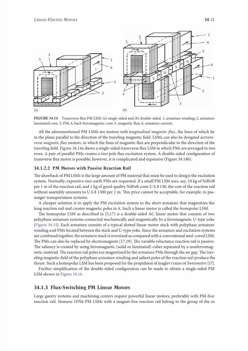
8102019 Power Handbook
httpslidepdfcomreaderfullpower-handbook 2643
34-11Linear Electric Motors
All the aorementioned PM LSMs are motors with longitudinal magnetic 1047298ux the lines o which lie
in the plane parallel to the direction o the traveling magnetic 1047297eld LSMs can also be designed as trans-
verse magnetic 1047298ux motors in which the lines o magnetic 1047298ux are perpendicular to the direction o the
traveling 1047297eld Figure 3414a shows a single-sided transverse 1047298ux LSM in which PMs are arranged in two
rows A pair o parallel PMs creates a two pole 1047298ux excitation system A double-sided con1047297guration o
transverse 1047298ux motor is possible however it is complicated and expensive (Figure 3414b)
34122 PM Motors with Passive Reaction Rail
Te drawback o PM LSMs is the large amount o PM material that must be used to design the excitation
system Normally expensive rare-earth PMs are requested I a small PM LSM uses say 10 kg o NdFeB
per 1 m o the reaction rail and 1 kg o good-quality NdFeB costs US$ 130 the cost o the reaction rail
without assembly amounts to US$ 1300 per 1 m Tis price cannot be acceptable or example in pas-
senger transportation systems
A cheaper solution is to apply the PM excitation system to the short armature that magnetizes the
long reaction rail and creates magnetic poles in it Such a linear motor is called the homopolar LSM
Te homopolar LSM as described in [517] is a double-sided AC linear motor that consists o two
polyphase armature systems connected mechanically and magnetically by a erromagnetic U-type yoke
(Figure 3415) Each armature consists o a typical slotted linear motor stack with polyphase armature
winding and PMs located between the stack and U-type yoke Since the armature and excitation systems
are combined together the armature stack is oversized as compared with a conventional steel-cored LSM
Te PMs can also be replaced by electromagnets [1719] Te variable reluctance reaction rail is passive
Te saliency is created by using erromagnetic (solid or laminated) cubes separated by a nonerromag-netic material Te reaction rail poles are magnetized by the armature PMs through the air gap Te trav-
eling magnetic 1047297eld o the polyphase armature winding and salient poles o the reaction rail produce the
thrust Such a homopolar LSM has been proposed or the propulsion o maglev trains o Swissmetro [17]
Further simpli1047297cation o the double-sided con1047297guration can be made to obtain a single-sided PM
LSM shown in Figure 3416
3413 Flux-Switching PM Linear Motors
Large gantry systems and machining centers require powerul linear motors preerably with PM-ree
reaction rail Siemens 1FN6 PM LSMs with a magnet-ree reaction rail belong to the group o the so
5
(a) (b)
5
N S
N
N
3
4
4
3
2
6
1
3
6
1
6
1
i
S
2
2
N
N
SNN
S
ransverse 1047298ux PM LSM (a) single-sided and (b) double-sided 1 armature winding 2 armature
laminated core 3 PM 4 back erromagnetic core 5 magnetic 1047298ux 6 armature current
8102019 Power Handbook
httpslidepdfcomreaderfullpower-handbook 2743
34-12 Electric Power Generation Transmission and Distribution
called 1047298ux-switching PM machines [1016] Te armature system is air cooled degree o protection IP23
class o insulation F line voltage rom 400 to 480 V rated thrust rom 235 to 2110 N maximum veloc-
ity at rated thrust rom 170 to 540 mmin (able 346) overload capacity 38 o rated thrust modular
type construction [20] Tese LSMs operate with Siemens Sinamics or Simodrive solid-state converters
and external encoders According to Siemens [20] these new LSMs produce thrust orces and velocities
equivalent to competitive classical models or light-duty machine tool machine accessory and material
handling applications
2 3 244 1
N
S
S
N
N
S
S
N
5
Single-sided PM LSM with a passive reaction rail 1 PM 2 armature winding 3 armature stack
4 yoke 5 erromagnetic reaction rail
1
1
2 343
5
Fe Fe Fe Fe
Double-sided homopolar PM LSM with passive reaction rail 1 PM 2 armature winding
3 armature stack 4 yoke 5 reaction rail
Speci1047297cations o 1FN6 PM LSMs Manuactured by Siemens Erlangen Germany
Armature Unit Rated Trust N Max Trust N
Max Speed at
Rated Trust
mmin
Max Speed at
Max Trust
mmin
Rated
Current A Max Current A
1FN6008-1LC17 235ndash350 900 263 103 17ndash26 90
1FN6008-1LC37 235ndash350 900 541 224 35ndash53 180
1FN6016-1LC30 470ndash710 1800 419 176 54ndash80 280
1FN6016-1LC17 935ndash1400 3590 263 101 70ndash105 360
1FN6024-1LC12 705ndash1060 2690 176 69 35ndash53 180
1FN6024-1LC20 705ndash1060 2690 277 114 54ndash80 280
1FN6024-1LG10 2110ndash3170 8080 172 62 105ndash160 540
1FN6024-1LG17 2110ndash3170 8080 270 102 162ndash243 840
Source Synchronous Linear Motor 1FN6 Te Electrical Gear Rack Siemens AG Industry Sector Drive echnologies
Motion Control Erlangen Germany 2008
8102019 Power Handbook
httpslidepdfcomreaderfullpower-handbook 2843
34-13Linear Electric Motors
Te magnet-ree reaction rail is easy to install and does not require the saety considerations o stan-
dard PM reaction rails Without PMs there is no problem with errous chips and other debris beingattracted to these sections Maintenance becomes a simple matter o installing a wiper or brush on the
moving part o the slide
Te 1047298ux-switching LSM comprises an armature section that is equipped with coils and PMs as well
as a nonmagnetic toothed reaction rail section (Figure 3417) Te key design innovation is an LSM in
which PMs are integrated directly into the lamination o the armature core along with the individual
windings or each phase Both magnitudes and polarities o the linkage 1047298ux in the armature winding
vary periodically along with the reaction rail movement Te magnetic 1047298ux between the armature core
and steel reaction rail is controlled by switching the three-phase armature currents according to a desig-
nated algorithm Te passive reaction rail consists o milled steel with poles (teeth) and is much simpler
to manuacture
3414 Motors with Electromagnetic Excitation
Te electromagnetic excitation system o an LSM is similar to the salient-pole rotor o a rotary
synchronous motor Figure 3418 shows a 1047298at single-sided LSM with salient erromagnetic poles and
DC 1047297eld excitation winding Te poles and pole shoes can be made o solid steel laminated steel or sin-
tered powder I the electromagnetic excitation system is integrated with the moving part the DC cur-
rent can be delivered with the aid o brushes and contact bars inductive power transer (IP) systems
linear transormers or linear brushless exciters
A AB BC C
1
2
3
4
5
v
τ2
τ1
Construction o 1047298ux-switching LSM with PM-ree reaction rail 1 laminated armature core
2 PM 3 armature coil (phase C) 4 toothed passive steel reaction rail 5 linkage magnetic 1047298ux (phase A is on)
1
3
τ τ
2
S
d d q q q
4
N
Electromagnetic excitation system o a 1047298at single-sided iron-cored LSM 1 salient pole 2 DC
excitation winding 3 erromagnetic rail (yoke) 4 armature system
8102019 Power Handbook
httpslidepdfcomreaderfullpower-handbook 2943
34-14 Electric Power Generation Transmission and Distribution
LSMs with electromagnetic excitation (wound-1047297eld reaction rail) are used in German ransrapid
maglev train (Figure 3419)
3415 Motors with Superconducting Excitation System
In large-power LSMs the electromagnets with erromagnetic core that produce the excitation 1047298ux can
be replaced by coreless SC electromagnets Since the magnetic 1047298ux density produced by the SC electro-
magnet is greater than the saturation magnetic 1047298ux density o the best laminated alloys ( Bsat asymp 24 or
cobalt alloy) there is no need to use the armature erromagnetic core An LSM with SC 1047297eld excitation
system is a totally air-cored machine (Figure 3420)
Experimental maglev trains on the Yamanashi Maglev est Line (YML) in Yamanashi Preecture(west rom okyo) Japan are driven by air-cored LSMs with SC excitation systems ( Figure 3421)
342 Linear Induction Motors
LIMs have ound the widest prospects or applications in transportation systems beginning with electri-
cal traction on small passenger or material supply cars (used at airports exhibitions electrohighways
elevators) and ending with pallet transportation waer transportation belt conveyors transportation
systems o bulk materials etc Te second important place or LIM applications is in industry ie man-
uacturing processes (machine tools hammers presses mills separators automated manuacturing systems
strip tensioners textile shuttles index tables turntables disk saws or wood sliding doors robots etc)
ransrapid 09 maglev train driven by LSMs with electromagnetic excitation (Photo courtesy oTyssen ransrapid System GmbH Munich Germany)
1
2A
B
C B
A
A
C
S SN
τ τ τ τ τ
N N
CBA
Tree-phase air-cored LSM with SC excitation system 1 armature coils 2 SC excitation coils
8102019 Power Handbook
httpslidepdfcomreaderfullpower-handbook 3043
34-15Linear Electric Motors
LIMs can also play an important part in industrial investigations and tests or example high acceleration
o model aircraf in aerodynamic tunnels high acceleration o vessels in laboratory pools propulsion o
mixers shakers and vibrators and adjusting xndashy tables and instruments Tere is also a possibility o
using LIMs in consumer electronics (sound and vision equipment knitting machines curtains) and in
offices (transportation o documents letters and cash) Te Handbook o Linear Motor Applications [21]
printed in Japan in 1986 contains about 50 examples o applications o LIMs in operation or in the pro-
cess o implementation
3421 Basic Geometries and Constructions
A LIM can be obtained by cutting in the same way either a cage rotor induction motor or a wound rotor
induction motor Te stator becomes the primary and the rotor becomes the secondary [12] Te secondary
o a LIM can be simpli1047297ed by using a solid steel core and replacing the cage (ladder) or slip-ring winding with
a high-conductivity nonerromagnetic plate (Al or Cu) Te nonerromagnetic plate is a secondary electric
circuit with distributed parameters and the erromagnetic core is a conductor both or the magnetic 1047298ux
and the electric current It does not matter rom the principle o operation point o view which part (primary
or secondary) is in motion Tus the 1047298at single-sided LIM can be obtained rom a solid rotor induction
motor (Figure 341a) and the 1047298at double-sided LIM can be obtained rom a hollow-rotor induction motor
with wound external and internal stator (Figure 341b) In a double-sided LIM the secondary erromagneticcore is not necessary since the magnetic 1047298ux excited by one o the primary windings afer passing through
the air gaps and nonerromagnetic secondary is then closed up by the core o the second primary unit
Teoretically a double-sided LIM with primary windings located on two cores in comparison with a
single-sided LIM exciting the same MMF has twice the air gap magnetic 1047298ux density Tereore the thrust
o such a motor is our times greater assuming the same dimensions I only one primary core is wound
the output parameters o a double-sided LIM are the same as those or a single-sided LIM with laminated
secondary back iron Te undamental advantage o double-sided LIMs is the elimination o the normal
attractive orce between the primary and the secondary because the secondary is usually nonerromagnetic
Flat LIMs can have primary cores consisting o an array o cores arranged in parallel at appropri-
ate distances and connected magnetically by additional yokes perpendicular to the direction o the
YML in Yamanashi Preecture (near okyo) Japan YML maglev trains use air-cored LSMs
with SC excitation system (Photo courtesy o Central Japan Railway Company and Railway echnical Research
Institute okyo Japan)
8102019 Power Handbook
httpslidepdfcomreaderfullpower-handbook 3143
34-16 Electric Power Generation Transmission and Distribution
traveling 1047297eld A magnetic circuit designed in such a way makes it possible to apply two windings in
general multiphase windings with perpendicular conductors as shown in Figure 3422 Adjusting the
current in each winding the secondary can be moved in two perpendicular directions and can be posi-
tioned at any point o the xndashy plane A 1047298at LIM with two degrees o reedom (DOFs) can be designed both
as single-sided and double-sided machines
By rolling a 1047298at single-sided or double-sided LIM around the axis parallel to the direction o the travel-
ing magnetic 1047297eld ie parallel to the direction o the thrust a tubular motor can be obtained (Figure 3423)
A tubular (cylindrical) LIM similar to a 1047298at LIM can be designed both as single-sided and double-
sided machines and can have a square or rectangular cross section as in Figure 3424 Tere are possible
Te primary o a 1047298at LIM with two DOFs
g
g
g 1
g 2
(c)
(b)
(a)
d
v
v
v
1
1
1 1
1
1
2
2
2
2
2
2
ubular LIMs (a) single-sided with an external short primary (b) single-sided with an external
short secondary and (c) double-sided with short primary 1 primary 2 secondary
8102019 Power Handbook
httpslidepdfcomreaderfullpower-handbook 3243
34-17Linear Electric Motors
con1047297gurations other than that in Figure 3423 regarding the length o the secondary with respect to thelength o the primary
All the aorementioned LIMs are motors with longitudinal magnetic 1047298ux ie the lines o magnetic
1047298ux lie in the plane parallel to the direction o the traveling magnetic 1047297eld A LIM can also be designed
in such a way as to obtain magnetic 1047298ux lines perpendicular to the direction o the traveling 1047297eld Such
motors are said to have transverse magnetic 1047298ux (Figure 3425)
Te undamental advantage o a LIM with transverse magnetic 1047298ux in comparison with a LIM with
longitudinal magnetic 1047298ux is the lower magnetizing current necessary due to the shorter magnetic 1047298ux
paths Te signi1047297cant disadvantage is lower thrust A 1047298at LIM with transverse magnetic 1047298ux usually has
a primary winding o concentrated coils located on salient poles
A 1047298at single-sided LIM with transverse 1047298ux can produce not only thrust but also electrodynamic
suspension In the design shown in Figure 3426 the secondary is suspended electrodynamically andpropelled and stabilized laterally by the primary magnetic 1047297eld [8] Te primary magnetic circuit con-
sists o E-shaped laminations assembled in two rows Te short secondary is made o light Al alloy in the
orm o a boat Te lateral sides o the boat are inclined by 60deg with respect to the active surace Such a
shape provides maximum normal repulsive orce and maximum lateral stabilization
According to their geometry the LIMs can be divided into the ollowing groups
bull With movable primary or movable secondary
bull Single sided and double sided
bull Flat and tubular
bull With short primary and short secondary
bull With longitudinal and transverse magnetic 1047298ux
1 2 3 4 1 2 3 4
ubular double-sided LIM with a square cross section 1 primary 2 secondary 3 primary coil
4 internal core
v
v
1 1
1
1
(a)
(b)
22
22
Flat LIM with transverse magnetic 1047298ux and salient poles (a) single-sided and (b) double-sided
1 primary 2 secondary
8102019 Power Handbook
httpslidepdfcomreaderfullpower-handbook 3343
34-18 Electric Power Generation Transmission and Distribution
Te linear speed o a LIM is
v s v s= minus( )1 (346)
where
s is the slip
v s is the synchronous speed according to Equation 341
Neglecting the longitudinal end effect [6] the electromagnetic thrust developed by a LIM can be
expressed in a similar way as or a rotary induction motor ie
F
m
v I
R
sdx
s
= prime( ) prime1
2
2 2
(347)
where
m1 is the number o phases o the primary winding
v s is the synchronous speed according to Equation 341
primeI 2 is the secondary current reerred to the primary system
primeR2 is the secondary resistance reerred to the primary system
s is the slip
Te secondary resistance primeR2 must include the so-called edge effect [6]
3422 Propulsion of Wheel-on-Rail Vehicles
Modern railway systems and electrical traction should meet the ollowing requirements
bull High level o automatization and computerization
bull Propulsion and braking independent o adhesion which in turn is affected 1047297rst o all by climate
and weather
bull Low level o noise sometimes below 70 dB (A)
Flat LIM with transverse magnetic 1047298ux salient poles and nonerromagnetic secondary pro-
pelled suspended and stabilized electrodynamically (From Gieras JF et al Analytical calculation o electro-
dynamic levitation orces in a special-purpose linear induction motor International Electric Machines and Drives
Conerence (IEMDCrsquo11) Niagara Falls Ontario Canada 2011 [on CD-ROM])
8102019 Power Handbook
httpslidepdfcomreaderfullpower-handbook 3443
34-19Linear Electric Motors
bull Ability to cope with high slopes at least 6 and sharp bends with radius o curvature less than 20 m
bull No pollution to natural environment and landscape
bull High reliability
Te congestion problems o big cities should be solved by creating collective transport orms that can be
implemented without affecting a highly populated city For example there are many cities in Italy where
the historical center has remained the same since the Renaissance A heavy railway might be a com-
pletely wrong solution and have a notable impact on the city planning An adequate solution might be
a light railway a people mover with transport capacity o 10000ndash20000 passengers per hour to replace
the traditional transport nets and to integrate the existing railway nets
All the requirements mentioned earlier can be met by using LIMs as propulsion machines Replacing
electrical rotary motors with linear motors in traction drives (electrical locomotives) generally does
not require new tracks but only their adjustment to linear drives Single-sided LIMs (Figure 3427a and b)
are best since the normal attractive orce o these can strengthen the adhesion o wheels and rails
Te air gap is rom 10 to 15 mm Most requently the motor car has two LIMs with short primaries
(Figure 3427a) assembled in series Te double-layer secondary consists o a solid back iron and an Al
cap and is located between the rails Cables or computer communication with the vehicle and quite
ofen collectors or electrical energy delivery to the vehicle are located along the track Tree-phaseLIMs are ed rom variable-voltage variable-requency (VVVF) voltage-source inverters A linear pro-
pulsion system o wheel-on-rail vehicles allows more 1047298exibility (Figure 3428) reducing noise on bends
and wear o the wheels and rails
Double-sided LIMs (Figure 3427c and d) have ound very limited application due to the technical
difficulty o eliminating aults caused by bends in the secondary with primary cores on either side It is
more difficult to keep a small and uniorm air gap in double-sided LIMs than that in single-sided LIMs
Te LIM-driven wheel-on-rail vehicles are built or low velocities ie less than 100 kmh and or
short routes ie less than 50 km (urban transit systems and short-distance trains) At present LIM-
driven trains operate in oronto and Vancouver BC Canada in Detroit MI (Figure 3429) okyo
(Figure 3430) and Osaka Japan and Kuala Lumpur Malaysia
(a) (b)
(c) (d)
LIM-driven wheel-on-rail cars (a) single-sided LIM with short primary mounted on the undercar-
riage (b) single-sided LIM with short secondary mounted on the undercarriage (c) double-sided LIM with short pri-
mary mounted on the undercarriage and (d) double-sided LIM with short secondary mounted on the undercarriage
8102019 Power Handbook
httpslidepdfcomreaderfullpower-handbook 3543
34-20 Electric Power Generation Transmission and Distribution
(a) (b)
Te undercarriage o a wheel-on-rail vehicle (a) rotary motor propulsion and (b) LIM propulsion
Detroit people mover driven by single-sided LIMs
oei Oedo subway line in okyo driven by single-sided LIMs
8102019 Power Handbook
httpslidepdfcomreaderfullpower-handbook 3643
34-21Linear Electric Motors
Te design data o some single-sided traction LIMs are presented in able 347 and double-sided trac-
tion LIMs in able 348
343 Variable Reluctance Motors
Te simplest construction o a variable reluctance LSM or linear reluctance motor (LRM) is that shown
in Figure 3418 with DC excitation winding being removed However the thrust o such a motor wouldbe low as the ratio o d -axis permeance to q-axis permeance is low Better perormance can be obtained
when using 1047298ux barriers [18] or steel laminations [15] o make 1047298ux barriers any nonerromagnetic
materials can be used o obtain high permeance (low reluctance) in the d -axis and low permeance in
the q-axis steel laminations should be oriented in such a way as to create high permeance or the d -axis
magnetic 1047298ux
Figure 3431a shows a variable reluctance platen with 1047298ux barriers and Figure 3431b shows how to
arrange steel laminations to obtain different reluctances in the d - and q-axes Te platen can be com-
posed o segments the length o which is equal to the pole pitchτ Each segment consists o semicircular
lamellas cut out rom electrotechnical sheet A 1047297lling or example epoxy resin is used to make the seg-
ment rigid and robust By putting the segments together a platen o any desired length can be obtained
Design Data o Single-Sided Tree-Phase LIMs or Propulsion o Vehicles
Quantity
LIM
UnitJLMDR ICS KU CIGG GEC
Pullout thrust at requency given
in the ollowing F x
125 90 35 17 07 kN
Input requency 200 400 250 400 600 Hz
Rated phase current V 1 2750 4650 1300 2000 2000 A
Number o poles 2 p 8 6 4 6 4 mdash
Number o turns per phase N 1 128 96 128 108 48 mdash
Equivalent diameter o conductor d 1 mdash 893 528 1115 81 mm
Number o parallel conductors mdash 1 mdash 19 1 mdash
Effective width o primary core Li 023 0216 029 0101 01715 m
Pole pitch τ 027 02868 030 025 020 m
Length o single end connection l e mdash 03483 mdash 02955 03685 m
Coil pitch wc 0225 01673 025 01944 01555 m
Air gap g 150 126 120 150 182 mm
Number o slots z 1( primez 1) 96(106) 72(79) 48(58) 54(61) 36(43) mdash
Width o slot b11 mdash 156 170 150 1308 mm
Width o slot opening b14 mdash 156 mdash 1044 1308 mm
Depth o slot h11 mdash 530 380 3421 6147 mm
Height o yoke h1 y mdash 436 393 7163 500 mm
Conductivity o back iron at 20degC σFe mdash 446 952 446 512 times106 Sm
Conductivity o Al cap at 20degC σ Al mdash 300 303 323 215 times106 Sm
Width o back iron w 03 024 03 0111 01715 m
Tickness o back iron hsec 190 125 250 254 474 mm
Tickness o Al cap d 50 45 50 45(25) 32 mm
Tickness o Al cap behind Fe core t ov 50 170 50 127 32 mm
Width o Al cap 030 032 040 0201 02985 m
JLMDR Japanese Linear Motor Driven Railcar Japan ICS Intermediate Capacity ransit System Canada KU
Kyushu University LIM Japan CIGG Canadian Inst o Guided Ground ransport Canada GEC General
Electric Company United States (z 1 ) is the number o hal 1047297lled slots
8102019 Power Handbook
httpslidepdfcomreaderfullpower-handbook 3743
34-22 Electric Power Generation Transmission and Distribution
344 Stepping Motors
A linear stepping motor has a concentrated armature winding wound on salient poles and PM excitation
rail or variable reluctance platen Te thrust is generated as an action o the armature magnetic 1047298ux and
PM 1047298ux (active platen) or the armature magnetic 1047298ux and salient erromagnetic poles (variable reluc-
tance platen) Stepping motors have no position eedback
Design Data o Double-Sided Tree-Phase LIMs or Propulsion
o Vehicles
Quantity
LIM
UnitGEC LIMVR
Maximum thrust at input requency F x given in the ollowing 085 1668 kN
Input requency 600 1730 Hz
Input phase current I 1 2000 20000 A
Number o poles 2 p 4 10 mdash
Number o turns per phase N 1 144 100 mdash
Diameter o conductor d 1 075 110 mm
Effective width o primary core Li 00869 0254 m
Pole pitch τ 01795 03556 m
Coil pitch wc 005 005 m
Number o slots z 1( primez 1) 36(45) 150(160) mdash
Width o slot b11 137 160 mm
Width o slot opening b14 137 mdash mm
Depth o slot h1 630 mdash mm
Height o yoke h1 y 239 mdash mm
Width o tooth c1 200 77 mm
Resultant air gap 2 g + d 381 38075 mm
Air gap g 2 times 127 2 times 111 mm
Tickness o secondary d 127 15875(hollow) mm
Effective thickness o Al secondary 127 72 mm
Width o secondary w ge03046 mdash m
Conductivity o Al cap at 20degC σ Al asymp2434 asymp240 times106 Sm
GEC General Electric Company United States LIMVR LIM Research Vehicle
Pueblo CO United States (z 1 ) is the number o hal 1047297lled slots
(a) (b)
q q d d d q d q d d
Laminations
τ τ τ τ
Epoxy resin
Variable reluctance LSMs with (a) 1047298ux barriers and (b) steel laminations
8102019 Power Handbook
httpslidepdfcomreaderfullpower-handbook 3843
8102019 Power Handbook
httpslidepdfcomreaderfullpower-handbook 3943
34-24 Electric Power Generation Transmission and Distribution
Tis value is different or ull-step and microstepping drives Te maximum startndashstop speed is the
maximum speed that can be used when starting or stopping the motor without ramping that does not
cause the motor to all out o synchronism or lose steps Te maximum speed is the maximum linear
speed that can be achieved without the motor stalling or alling out o synchronism Te maximum
load mass is the maximum allowable mass applied to the orcer against the scale that does not result in
mechanical damage Te ull-step resolution is the position increment obtained when the currents are
switched rom one winding to the next winding Tis is the typical resolution obtained with ul l-step
drives and it is strictly a unction o the motor construction Te microstepping resolution is the position
increment obtained when the ull-step resolution is divided electronically by proportioning the currents
in the two windings Tis resolution is typically 10ndash250 times smaller than the ull-step resolution [13]
HLSMs are regarded as an excellent solution to positioning systems that require a high accuracy
and rapid acceleration With a microprocessor controlled microstepping mode a smooth operation with
standard resolution o a ew hundred stepsmm can be obtained Te advantages such as high efficiencyhigh throughput mechanical simplicity high reliability precise open-loop operation and low inertia
o the system have made these kind o motors more and more attractive in such applications as actory
automation high speed positioning computer peripherals acsimile machines numerically controlled
machine tools automated medical equipment automated laboratory equipment and welding robots
Tis motor is especially suitable or machine tools printers plotters and computer-controlled material
handling in which a high positioning accuracy and repeatability are the key problems
When two or our orcers mounted at 90deg and a special grooved platen (ldquowaffle platerdquo) are used the
xndashy motion (two DOFs) in a single plane is obtained (Figure 3434)
Speci1047297cation data o the xndashy HLSMs manuactured by Normag Northern Magnetics Inc Santa
Clarita CA are given in able 3410
PM linear stepping motors (Photo courtesy o okyo Aircraf Instrument Co Ltd okyo Japan)
8102019 Power Handbook
httpslidepdfcomreaderfullpower-handbook 4043
34-25Linear Electric Motors
345 Switched Reluctance Motors
Te topology o a linear switched reluctance motor is similar to that o a stepping motor with variable
reluctance platen In addition it is equipped with position sensors Te turn-on and turn-off instant o
the input current is synchronized with the position o the moving part Te thrust is very sensitive to
the turn-on and turn-off instant
In the case o a linear stepping or linear switched reluctance motor the speed v o the moving part is
v v s sw= = τ
(348)
where
sw is the undamental switching requency in one armature phase winding
τ is the pole pitch o the reaction rail
For a rotary stepping or switched reluctance motor sw = 2 pr n where 2 pr is the number o rotor poles and
n is rotational speed in revs
A linear switched reluctance motor has a doubly salient magnetic circuit with a polyphase winding
on the armature Longitudinal and transverse 1047298ux designs are shown in Figure 3435 A linear switched
reluctance motor allows precise speed and position-controlled linear motion at low speeds and is not sub-
ject to design constraints (minimum speed limited by minimum easible pole pitch) o linear AC motors
x
y
12
3
4
1
1
2
2
HLSM with a our-unit orcer to obtain the xndashy motion 1 orcers or the x -direction 2 orcers
or the y -direction 3 platen 4 air pressure
Data o xndashy HLSMs Manuactured by Normag Northern Magnetics Inc
Santa Clarita CA
Parameter 4XY0602-2-0 4XY2002-2-0 4XY2004-2-0 4XY2504-2-0
Number o orcer units per axis 1 1 2 2
Number o phases 2 2 2(4) 2(4)Static thrust N 133 400 980 1330
Trust at 1 ms N 111 311 712 980
Normal attractive orce N 1600 4000 14400 18000
Resistance per phase Ω 29 33 16 19
Inductance per phase mH 15 40 20 23
Input phase current A 20 20 40 40
Air gap mm 002
Maximum temperature degC 110
Mass kg 32 072 20 15
Repeatability mm 000254
Resolution mm 000254
Bearing type Air
8102019 Power Handbook
httpslidepdfcomreaderfullpower-handbook 4143
34-26 Electric Power Generation Transmission and Distribution
346 Linear Positioning Stages
Linear motors are now playing a key role in advanced precision linear positioning Linear precision posi-
tioning systems can be classi1047297ed into open-loop systems with HLSMs and closed-loop servo systems
with LSMs LBMs or LIMs
A PM LSMndashdriven positioning stage is shown in Figure 3436 A stationary base is made o Al steel
ceramic or granite plate It provides a stable precise and 1047298at platorm to which all stationary position-
ing components are attached Te base o the stage is attached to the host system with the aid o mount-
ing screws
Te moving table accommodates all moving positioning components o achieve maximum accelera-
tion the mass o the moving table should be as small as possible and usually Al is used as a lightweight
material A number o mounting holes on the moving table is necessary to 1047297x the payload to the mount-
ing table
Linear bearing rails provide a precise guidance to the moving table A minimum o one bearing rail
is required Linear ball bearing or air bearings are attached to each rail
Te armature o a linear motor is astened to the moving table and reaction rail (PM excitation sys-tem) is built in the base between the rails (Figure 3436)
A linear encoder is needed to obtain precise control o position o the table velocity and acceleration
Te read head o the encoder is attached to the moving table
(a) (b)
3
3
221
1
Linear switched reluctance motor con1047297gurations (a) longitudinal 1047298ux design and (b) transverse
1047298ux design 1 armature winding 2 armature stack 3 platen
12
3
5
4
7
6
8
Linear positioning stage driven by PM LBM 1 base 2 moving table 3 armature o LBM 4 PMs
5 linear bearing 6 encoder 7 cable carrier 8 limit switch (Courtesy o Normag Santa Clarita CA)
8102019 Power Handbook
httpslidepdfcomreaderfullpower-handbook 4243
34-27Linear Electric Motors
Noncontact limit switches ixed to the base provide an overtravel protection and init ial homing
A cable carrier accommodates and routes electrical cables between the moving table and stationary
connector box 1047297xed to the base
An HLSM-driven linear precision stage is o similar construction Instead o PMs between bearing
rails it has a variable reluctance platen HLSMs usually need air bearings and in addition to the electri-
cal cables an air hose between air bearings and the compressor is requiredLinear positioning stages are used in semiconductor technology electronic assembly quality assur-
ance laser cutting optical scanning water jet cutting gantry systems (x y z stages) color printers
plotters and Cartesian coordinate robotics
References
1 Anorad Linear Motors Inormation Brochure Anorad Hauppauge New York 2007 wwwanoradcom
2 Boldea I and Nasar SA Linear Motion Electromagnetic Systems John Wiley amp Sons New York 1985
3 Boldea I and Nasar SA Linear Electric Actuators and Generators Cambridge University Press
New York 2005
4 Compumotor Digiplan Positioning Control Systems and Drives Parker Hanni1047297n CorporationRohnert Park CA 2011
5 Everes W Henneberger G Wunderlich H and Selig A A linear homopolar motor or a trans-
portation system 2nd International Symposium on Linear Drives or Industry Applications (LDIArsquo98)
okyo Japan 1998 pp 46ndash49
6 Gieras JF Linear Induction Drives Clarendon Press Oxord UK 1994
7 Gieras JF Status o linear motors in the United States International Symposium on Linear Drives
or Industry Applications (LDIArsquo03) Birmingham UK 2003 pp 169ndash176
8 Gieras JF Gientkowski Z Mews J and Splawski P Analytical calculation o electrodynamic
levitation orces in a special-purpose linear induction motor International Electric Machines and
Drives Conerence (IEMDCrsquo11) Niagara Falls Ontario Canada 2011 [on CD-ROM]
9 Gieras JF Piech ZJ and omczuk BZ Linear Synchronous Motors ransportation and Automation Systems aylor amp Francis (CRC Press) Boca Raton FL 2011
10 Hoang E Ahmed AHB and Lucidarme J Switching 1047298ux permanent magnet polyphase syn-
chronous machines 7th European Conerence on Power Electronics and Applications (EPErsquo97)
Vol 3 rondheim Norway 1977 pp 903ndash908
11 Kollmorgen Linear Motors Aim to Cut Cost o Semiconductors and Electronics Manuacture
Kollmorgen Radord VA 1997
12 Laithwaite ER A History o Linear Electric Motors Macmillan London UK 1987
13 Linear Step Motor Inormation Brochure okyo Aircraf Instrument Co Ltd okyo Japan
1998
14 LinMot Design Manual Sulzer Electronics Ltd Zuumlrich Switzerland 1999
15 Locci N and Marongiu I Modelling and testing a new linear reluctance motor InternationalConerence on Electrical Machines (ICEMrsquo92) Vol 2 Manchester UK 1992 pp 706ndash710
16 Rauch SE and Johnson LJ Design principles o 1047298ux-switch alternators AIEE rans Part III
74(12) 1261ndash1269 1955
17 Rosenmayr M Casat Glavitsch A and Stemmler H SwissmetromdashPower supply or a high-
power-propulsion system with short stator linear motors 15th International Conerence on
Magnetically Levitated Systems and Linear Drives Maglevrsquo98 Mount Fuji Yamanashi Japan 1998
pp 280ndash286
18 Sanada M Morimoto S and akeda Y Reluctance equalization design o multi 1047298ux barrier con-
struction or linear synchronous reluctance motors 2nd International Symposium on Linear Drives
or Industrial Applications (LDIArsquo98) okyo Japan 1998 pp 259ndash262
8102019 Power Handbook
httpslidepdfcomreaderfullpower-handbook 4343
34-28 Electric Power Generation Transmission and Distribution
19 Seok-Myeong J and Sang-Sub J Design and analysis o the linear homopolar synchronous motor
or integrated magnetic propulsion and suspension 2nd International Symposium on Linear Drives
or Industrial Applications (LDIArsquo98) okyo Japan 1998 pp 74ndash77
20 Synchronous Linear Motor 1FN6 Te Electrical Gear Rack Siemens AG Industry Sector Drive
echnologies Motion Control Erlangen Germany 2008
21 Yamada H Handbook o Linear Motor Applications (in Japanese) Kogyo Chosaki Publishing Cookyo Japan 1986
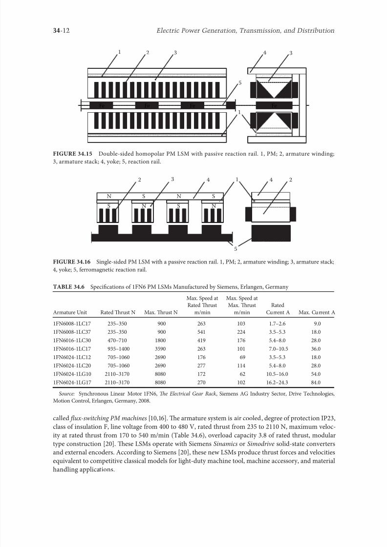
8102019 Power Handbook
httpslidepdfcomreaderfullpower-handbook 2743
34-12 Electric Power Generation Transmission and Distribution
called 1047298ux-switching PM machines [1016] Te armature system is air cooled degree o protection IP23
class o insulation F line voltage rom 400 to 480 V rated thrust rom 235 to 2110 N maximum veloc-
ity at rated thrust rom 170 to 540 mmin (able 346) overload capacity 38 o rated thrust modular
type construction [20] Tese LSMs operate with Siemens Sinamics or Simodrive solid-state converters
and external encoders According to Siemens [20] these new LSMs produce thrust orces and velocities
equivalent to competitive classical models or light-duty machine tool machine accessory and material
handling applications
2 3 244 1
N
S
S
N
N
S
S
N
5
Single-sided PM LSM with a passive reaction rail 1 PM 2 armature winding 3 armature stack
4 yoke 5 erromagnetic reaction rail
1
1
2 343
5
Fe Fe Fe Fe
Double-sided homopolar PM LSM with passive reaction rail 1 PM 2 armature winding
3 armature stack 4 yoke 5 reaction rail
Speci1047297cations o 1FN6 PM LSMs Manuactured by Siemens Erlangen Germany
Armature Unit Rated Trust N Max Trust N
Max Speed at
Rated Trust
mmin
Max Speed at
Max Trust
mmin
Rated
Current A Max Current A
1FN6008-1LC17 235ndash350 900 263 103 17ndash26 90
1FN6008-1LC37 235ndash350 900 541 224 35ndash53 180
1FN6016-1LC30 470ndash710 1800 419 176 54ndash80 280
1FN6016-1LC17 935ndash1400 3590 263 101 70ndash105 360
1FN6024-1LC12 705ndash1060 2690 176 69 35ndash53 180
1FN6024-1LC20 705ndash1060 2690 277 114 54ndash80 280
1FN6024-1LG10 2110ndash3170 8080 172 62 105ndash160 540
1FN6024-1LG17 2110ndash3170 8080 270 102 162ndash243 840
Source Synchronous Linear Motor 1FN6 Te Electrical Gear Rack Siemens AG Industry Sector Drive echnologies
Motion Control Erlangen Germany 2008
8102019 Power Handbook
httpslidepdfcomreaderfullpower-handbook 2843
34-13Linear Electric Motors
Te magnet-ree reaction rail is easy to install and does not require the saety considerations o stan-
dard PM reaction rails Without PMs there is no problem with errous chips and other debris beingattracted to these sections Maintenance becomes a simple matter o installing a wiper or brush on the
moving part o the slide
Te 1047298ux-switching LSM comprises an armature section that is equipped with coils and PMs as well
as a nonmagnetic toothed reaction rail section (Figure 3417) Te key design innovation is an LSM in
which PMs are integrated directly into the lamination o the armature core along with the individual
windings or each phase Both magnitudes and polarities o the linkage 1047298ux in the armature winding
vary periodically along with the reaction rail movement Te magnetic 1047298ux between the armature core
and steel reaction rail is controlled by switching the three-phase armature currents according to a desig-
nated algorithm Te passive reaction rail consists o milled steel with poles (teeth) and is much simpler
to manuacture
3414 Motors with Electromagnetic Excitation
Te electromagnetic excitation system o an LSM is similar to the salient-pole rotor o a rotary
synchronous motor Figure 3418 shows a 1047298at single-sided LSM with salient erromagnetic poles and
DC 1047297eld excitation winding Te poles and pole shoes can be made o solid steel laminated steel or sin-
tered powder I the electromagnetic excitation system is integrated with the moving part the DC cur-
rent can be delivered with the aid o brushes and contact bars inductive power transer (IP) systems
linear transormers or linear brushless exciters
A AB BC C
1
2
3
4
5
v
τ2
τ1
Construction o 1047298ux-switching LSM with PM-ree reaction rail 1 laminated armature core
2 PM 3 armature coil (phase C) 4 toothed passive steel reaction rail 5 linkage magnetic 1047298ux (phase A is on)
1
3
τ τ
2
S
d d q q q
4
N
Electromagnetic excitation system o a 1047298at single-sided iron-cored LSM 1 salient pole 2 DC
excitation winding 3 erromagnetic rail (yoke) 4 armature system
8102019 Power Handbook
httpslidepdfcomreaderfullpower-handbook 2943
34-14 Electric Power Generation Transmission and Distribution
LSMs with electromagnetic excitation (wound-1047297eld reaction rail) are used in German ransrapid
maglev train (Figure 3419)
3415 Motors with Superconducting Excitation System
In large-power LSMs the electromagnets with erromagnetic core that produce the excitation 1047298ux can
be replaced by coreless SC electromagnets Since the magnetic 1047298ux density produced by the SC electro-
magnet is greater than the saturation magnetic 1047298ux density o the best laminated alloys ( Bsat asymp 24 or
cobalt alloy) there is no need to use the armature erromagnetic core An LSM with SC 1047297eld excitation
system is a totally air-cored machine (Figure 3420)
Experimental maglev trains on the Yamanashi Maglev est Line (YML) in Yamanashi Preecture(west rom okyo) Japan are driven by air-cored LSMs with SC excitation systems ( Figure 3421)
342 Linear Induction Motors
LIMs have ound the widest prospects or applications in transportation systems beginning with electri-
cal traction on small passenger or material supply cars (used at airports exhibitions electrohighways
elevators) and ending with pallet transportation waer transportation belt conveyors transportation
systems o bulk materials etc Te second important place or LIM applications is in industry ie man-
uacturing processes (machine tools hammers presses mills separators automated manuacturing systems
strip tensioners textile shuttles index tables turntables disk saws or wood sliding doors robots etc)
ransrapid 09 maglev train driven by LSMs with electromagnetic excitation (Photo courtesy oTyssen ransrapid System GmbH Munich Germany)
1
2A
B
C B
A
A
C
S SN
τ τ τ τ τ
N N
CBA
Tree-phase air-cored LSM with SC excitation system 1 armature coils 2 SC excitation coils
8102019 Power Handbook
httpslidepdfcomreaderfullpower-handbook 3043
34-15Linear Electric Motors
LIMs can also play an important part in industrial investigations and tests or example high acceleration
o model aircraf in aerodynamic tunnels high acceleration o vessels in laboratory pools propulsion o
mixers shakers and vibrators and adjusting xndashy tables and instruments Tere is also a possibility o
using LIMs in consumer electronics (sound and vision equipment knitting machines curtains) and in
offices (transportation o documents letters and cash) Te Handbook o Linear Motor Applications [21]
printed in Japan in 1986 contains about 50 examples o applications o LIMs in operation or in the pro-
cess o implementation
3421 Basic Geometries and Constructions
A LIM can be obtained by cutting in the same way either a cage rotor induction motor or a wound rotor
induction motor Te stator becomes the primary and the rotor becomes the secondary [12] Te secondary
o a LIM can be simpli1047297ed by using a solid steel core and replacing the cage (ladder) or slip-ring winding with
a high-conductivity nonerromagnetic plate (Al or Cu) Te nonerromagnetic plate is a secondary electric
circuit with distributed parameters and the erromagnetic core is a conductor both or the magnetic 1047298ux
and the electric current It does not matter rom the principle o operation point o view which part (primary
or secondary) is in motion Tus the 1047298at single-sided LIM can be obtained rom a solid rotor induction
motor (Figure 341a) and the 1047298at double-sided LIM can be obtained rom a hollow-rotor induction motor
with wound external and internal stator (Figure 341b) In a double-sided LIM the secondary erromagneticcore is not necessary since the magnetic 1047298ux excited by one o the primary windings afer passing through
the air gaps and nonerromagnetic secondary is then closed up by the core o the second primary unit
Teoretically a double-sided LIM with primary windings located on two cores in comparison with a
single-sided LIM exciting the same MMF has twice the air gap magnetic 1047298ux density Tereore the thrust
o such a motor is our times greater assuming the same dimensions I only one primary core is wound
the output parameters o a double-sided LIM are the same as those or a single-sided LIM with laminated
secondary back iron Te undamental advantage o double-sided LIMs is the elimination o the normal
attractive orce between the primary and the secondary because the secondary is usually nonerromagnetic
Flat LIMs can have primary cores consisting o an array o cores arranged in parallel at appropri-
ate distances and connected magnetically by additional yokes perpendicular to the direction o the
YML in Yamanashi Preecture (near okyo) Japan YML maglev trains use air-cored LSMs
with SC excitation system (Photo courtesy o Central Japan Railway Company and Railway echnical Research
Institute okyo Japan)
8102019 Power Handbook
httpslidepdfcomreaderfullpower-handbook 3143
34-16 Electric Power Generation Transmission and Distribution
traveling 1047297eld A magnetic circuit designed in such a way makes it possible to apply two windings in
general multiphase windings with perpendicular conductors as shown in Figure 3422 Adjusting the
current in each winding the secondary can be moved in two perpendicular directions and can be posi-
tioned at any point o the xndashy plane A 1047298at LIM with two degrees o reedom (DOFs) can be designed both
as single-sided and double-sided machines
By rolling a 1047298at single-sided or double-sided LIM around the axis parallel to the direction o the travel-
ing magnetic 1047297eld ie parallel to the direction o the thrust a tubular motor can be obtained (Figure 3423)
A tubular (cylindrical) LIM similar to a 1047298at LIM can be designed both as single-sided and double-
sided machines and can have a square or rectangular cross section as in Figure 3424 Tere are possible
Te primary o a 1047298at LIM with two DOFs
g
g
g 1
g 2
(c)
(b)
(a)
d
v
v
v
1
1
1 1
1
1
2
2
2
2
2
2
ubular LIMs (a) single-sided with an external short primary (b) single-sided with an external
short secondary and (c) double-sided with short primary 1 primary 2 secondary
8102019 Power Handbook
httpslidepdfcomreaderfullpower-handbook 3243
34-17Linear Electric Motors
con1047297gurations other than that in Figure 3423 regarding the length o the secondary with respect to thelength o the primary
All the aorementioned LIMs are motors with longitudinal magnetic 1047298ux ie the lines o magnetic
1047298ux lie in the plane parallel to the direction o the traveling magnetic 1047297eld A LIM can also be designed
in such a way as to obtain magnetic 1047298ux lines perpendicular to the direction o the traveling 1047297eld Such
motors are said to have transverse magnetic 1047298ux (Figure 3425)
Te undamental advantage o a LIM with transverse magnetic 1047298ux in comparison with a LIM with
longitudinal magnetic 1047298ux is the lower magnetizing current necessary due to the shorter magnetic 1047298ux
paths Te signi1047297cant disadvantage is lower thrust A 1047298at LIM with transverse magnetic 1047298ux usually has
a primary winding o concentrated coils located on salient poles
A 1047298at single-sided LIM with transverse 1047298ux can produce not only thrust but also electrodynamic
suspension In the design shown in Figure 3426 the secondary is suspended electrodynamically andpropelled and stabilized laterally by the primary magnetic 1047297eld [8] Te primary magnetic circuit con-
sists o E-shaped laminations assembled in two rows Te short secondary is made o light Al alloy in the
orm o a boat Te lateral sides o the boat are inclined by 60deg with respect to the active surace Such a
shape provides maximum normal repulsive orce and maximum lateral stabilization
According to their geometry the LIMs can be divided into the ollowing groups
bull With movable primary or movable secondary
bull Single sided and double sided
bull Flat and tubular
bull With short primary and short secondary
bull With longitudinal and transverse magnetic 1047298ux
1 2 3 4 1 2 3 4
ubular double-sided LIM with a square cross section 1 primary 2 secondary 3 primary coil
4 internal core
v
v
1 1
1
1
(a)
(b)
22
22
Flat LIM with transverse magnetic 1047298ux and salient poles (a) single-sided and (b) double-sided
1 primary 2 secondary
8102019 Power Handbook
httpslidepdfcomreaderfullpower-handbook 3343
34-18 Electric Power Generation Transmission and Distribution
Te linear speed o a LIM is
v s v s= minus( )1 (346)
where
s is the slip
v s is the synchronous speed according to Equation 341
Neglecting the longitudinal end effect [6] the electromagnetic thrust developed by a LIM can be
expressed in a similar way as or a rotary induction motor ie
F
m
v I
R
sdx
s
= prime( ) prime1
2
2 2
(347)
where
m1 is the number o phases o the primary winding
v s is the synchronous speed according to Equation 341
primeI 2 is the secondary current reerred to the primary system
primeR2 is the secondary resistance reerred to the primary system
s is the slip
Te secondary resistance primeR2 must include the so-called edge effect [6]
3422 Propulsion of Wheel-on-Rail Vehicles
Modern railway systems and electrical traction should meet the ollowing requirements
bull High level o automatization and computerization
bull Propulsion and braking independent o adhesion which in turn is affected 1047297rst o all by climate
and weather
bull Low level o noise sometimes below 70 dB (A)
Flat LIM with transverse magnetic 1047298ux salient poles and nonerromagnetic secondary pro-
pelled suspended and stabilized electrodynamically (From Gieras JF et al Analytical calculation o electro-
dynamic levitation orces in a special-purpose linear induction motor International Electric Machines and Drives
Conerence (IEMDCrsquo11) Niagara Falls Ontario Canada 2011 [on CD-ROM])
8102019 Power Handbook
httpslidepdfcomreaderfullpower-handbook 3443
34-19Linear Electric Motors
bull Ability to cope with high slopes at least 6 and sharp bends with radius o curvature less than 20 m
bull No pollution to natural environment and landscape
bull High reliability
Te congestion problems o big cities should be solved by creating collective transport orms that can be
implemented without affecting a highly populated city For example there are many cities in Italy where
the historical center has remained the same since the Renaissance A heavy railway might be a com-
pletely wrong solution and have a notable impact on the city planning An adequate solution might be
a light railway a people mover with transport capacity o 10000ndash20000 passengers per hour to replace
the traditional transport nets and to integrate the existing railway nets
All the requirements mentioned earlier can be met by using LIMs as propulsion machines Replacing
electrical rotary motors with linear motors in traction drives (electrical locomotives) generally does
not require new tracks but only their adjustment to linear drives Single-sided LIMs (Figure 3427a and b)
are best since the normal attractive orce o these can strengthen the adhesion o wheels and rails
Te air gap is rom 10 to 15 mm Most requently the motor car has two LIMs with short primaries
(Figure 3427a) assembled in series Te double-layer secondary consists o a solid back iron and an Al
cap and is located between the rails Cables or computer communication with the vehicle and quite
ofen collectors or electrical energy delivery to the vehicle are located along the track Tree-phaseLIMs are ed rom variable-voltage variable-requency (VVVF) voltage-source inverters A linear pro-
pulsion system o wheel-on-rail vehicles allows more 1047298exibility (Figure 3428) reducing noise on bends
and wear o the wheels and rails
Double-sided LIMs (Figure 3427c and d) have ound very limited application due to the technical
difficulty o eliminating aults caused by bends in the secondary with primary cores on either side It is
more difficult to keep a small and uniorm air gap in double-sided LIMs than that in single-sided LIMs
Te LIM-driven wheel-on-rail vehicles are built or low velocities ie less than 100 kmh and or
short routes ie less than 50 km (urban transit systems and short-distance trains) At present LIM-
driven trains operate in oronto and Vancouver BC Canada in Detroit MI (Figure 3429) okyo
(Figure 3430) and Osaka Japan and Kuala Lumpur Malaysia
(a) (b)
(c) (d)
LIM-driven wheel-on-rail cars (a) single-sided LIM with short primary mounted on the undercar-
riage (b) single-sided LIM with short secondary mounted on the undercarriage (c) double-sided LIM with short pri-
mary mounted on the undercarriage and (d) double-sided LIM with short secondary mounted on the undercarriage
8102019 Power Handbook
httpslidepdfcomreaderfullpower-handbook 3543
34-20 Electric Power Generation Transmission and Distribution
(a) (b)
Te undercarriage o a wheel-on-rail vehicle (a) rotary motor propulsion and (b) LIM propulsion
Detroit people mover driven by single-sided LIMs
oei Oedo subway line in okyo driven by single-sided LIMs
8102019 Power Handbook
httpslidepdfcomreaderfullpower-handbook 3643
34-21Linear Electric Motors
Te design data o some single-sided traction LIMs are presented in able 347 and double-sided trac-
tion LIMs in able 348
343 Variable Reluctance Motors
Te simplest construction o a variable reluctance LSM or linear reluctance motor (LRM) is that shown
in Figure 3418 with DC excitation winding being removed However the thrust o such a motor wouldbe low as the ratio o d -axis permeance to q-axis permeance is low Better perormance can be obtained
when using 1047298ux barriers [18] or steel laminations [15] o make 1047298ux barriers any nonerromagnetic
materials can be used o obtain high permeance (low reluctance) in the d -axis and low permeance in
the q-axis steel laminations should be oriented in such a way as to create high permeance or the d -axis
magnetic 1047298ux
Figure 3431a shows a variable reluctance platen with 1047298ux barriers and Figure 3431b shows how to
arrange steel laminations to obtain different reluctances in the d - and q-axes Te platen can be com-
posed o segments the length o which is equal to the pole pitchτ Each segment consists o semicircular
lamellas cut out rom electrotechnical sheet A 1047297lling or example epoxy resin is used to make the seg-
ment rigid and robust By putting the segments together a platen o any desired length can be obtained
Design Data o Single-Sided Tree-Phase LIMs or Propulsion o Vehicles
Quantity
LIM
UnitJLMDR ICS KU CIGG GEC
Pullout thrust at requency given
in the ollowing F x
125 90 35 17 07 kN
Input requency 200 400 250 400 600 Hz
Rated phase current V 1 2750 4650 1300 2000 2000 A
Number o poles 2 p 8 6 4 6 4 mdash
Number o turns per phase N 1 128 96 128 108 48 mdash
Equivalent diameter o conductor d 1 mdash 893 528 1115 81 mm
Number o parallel conductors mdash 1 mdash 19 1 mdash
Effective width o primary core Li 023 0216 029 0101 01715 m
Pole pitch τ 027 02868 030 025 020 m
Length o single end connection l e mdash 03483 mdash 02955 03685 m
Coil pitch wc 0225 01673 025 01944 01555 m
Air gap g 150 126 120 150 182 mm
Number o slots z 1( primez 1) 96(106) 72(79) 48(58) 54(61) 36(43) mdash
Width o slot b11 mdash 156 170 150 1308 mm
Width o slot opening b14 mdash 156 mdash 1044 1308 mm
Depth o slot h11 mdash 530 380 3421 6147 mm
Height o yoke h1 y mdash 436 393 7163 500 mm
Conductivity o back iron at 20degC σFe mdash 446 952 446 512 times106 Sm
Conductivity o Al cap at 20degC σ Al mdash 300 303 323 215 times106 Sm
Width o back iron w 03 024 03 0111 01715 m
Tickness o back iron hsec 190 125 250 254 474 mm
Tickness o Al cap d 50 45 50 45(25) 32 mm
Tickness o Al cap behind Fe core t ov 50 170 50 127 32 mm
Width o Al cap 030 032 040 0201 02985 m
JLMDR Japanese Linear Motor Driven Railcar Japan ICS Intermediate Capacity ransit System Canada KU
Kyushu University LIM Japan CIGG Canadian Inst o Guided Ground ransport Canada GEC General
Electric Company United States (z 1 ) is the number o hal 1047297lled slots
8102019 Power Handbook
httpslidepdfcomreaderfullpower-handbook 3743
34-22 Electric Power Generation Transmission and Distribution
344 Stepping Motors
A linear stepping motor has a concentrated armature winding wound on salient poles and PM excitation
rail or variable reluctance platen Te thrust is generated as an action o the armature magnetic 1047298ux and
PM 1047298ux (active platen) or the armature magnetic 1047298ux and salient erromagnetic poles (variable reluc-
tance platen) Stepping motors have no position eedback
Design Data o Double-Sided Tree-Phase LIMs or Propulsion
o Vehicles
Quantity
LIM
UnitGEC LIMVR
Maximum thrust at input requency F x given in the ollowing 085 1668 kN
Input requency 600 1730 Hz
Input phase current I 1 2000 20000 A
Number o poles 2 p 4 10 mdash
Number o turns per phase N 1 144 100 mdash
Diameter o conductor d 1 075 110 mm
Effective width o primary core Li 00869 0254 m
Pole pitch τ 01795 03556 m
Coil pitch wc 005 005 m
Number o slots z 1( primez 1) 36(45) 150(160) mdash
Width o slot b11 137 160 mm
Width o slot opening b14 137 mdash mm
Depth o slot h1 630 mdash mm
Height o yoke h1 y 239 mdash mm
Width o tooth c1 200 77 mm
Resultant air gap 2 g + d 381 38075 mm
Air gap g 2 times 127 2 times 111 mm
Tickness o secondary d 127 15875(hollow) mm
Effective thickness o Al secondary 127 72 mm
Width o secondary w ge03046 mdash m
Conductivity o Al cap at 20degC σ Al asymp2434 asymp240 times106 Sm
GEC General Electric Company United States LIMVR LIM Research Vehicle
Pueblo CO United States (z 1 ) is the number o hal 1047297lled slots
(a) (b)
q q d d d q d q d d
Laminations
τ τ τ τ
Epoxy resin
Variable reluctance LSMs with (a) 1047298ux barriers and (b) steel laminations
8102019 Power Handbook
httpslidepdfcomreaderfullpower-handbook 3843
8102019 Power Handbook
httpslidepdfcomreaderfullpower-handbook 3943
34-24 Electric Power Generation Transmission and Distribution
Tis value is different or ull-step and microstepping drives Te maximum startndashstop speed is the
maximum speed that can be used when starting or stopping the motor without ramping that does not
cause the motor to all out o synchronism or lose steps Te maximum speed is the maximum linear
speed that can be achieved without the motor stalling or alling out o synchronism Te maximum
load mass is the maximum allowable mass applied to the orcer against the scale that does not result in
mechanical damage Te ull-step resolution is the position increment obtained when the currents are
switched rom one winding to the next winding Tis is the typical resolution obtained with ul l-step
drives and it is strictly a unction o the motor construction Te microstepping resolution is the position
increment obtained when the ull-step resolution is divided electronically by proportioning the currents
in the two windings Tis resolution is typically 10ndash250 times smaller than the ull-step resolution [13]
HLSMs are regarded as an excellent solution to positioning systems that require a high accuracy
and rapid acceleration With a microprocessor controlled microstepping mode a smooth operation with
standard resolution o a ew hundred stepsmm can be obtained Te advantages such as high efficiencyhigh throughput mechanical simplicity high reliability precise open-loop operation and low inertia
o the system have made these kind o motors more and more attractive in such applications as actory
automation high speed positioning computer peripherals acsimile machines numerically controlled
machine tools automated medical equipment automated laboratory equipment and welding robots
Tis motor is especially suitable or machine tools printers plotters and computer-controlled material
handling in which a high positioning accuracy and repeatability are the key problems
When two or our orcers mounted at 90deg and a special grooved platen (ldquowaffle platerdquo) are used the
xndashy motion (two DOFs) in a single plane is obtained (Figure 3434)
Speci1047297cation data o the xndashy HLSMs manuactured by Normag Northern Magnetics Inc Santa
Clarita CA are given in able 3410
PM linear stepping motors (Photo courtesy o okyo Aircraf Instrument Co Ltd okyo Japan)
8102019 Power Handbook
httpslidepdfcomreaderfullpower-handbook 4043
34-25Linear Electric Motors
345 Switched Reluctance Motors
Te topology o a linear switched reluctance motor is similar to that o a stepping motor with variable
reluctance platen In addition it is equipped with position sensors Te turn-on and turn-off instant o
the input current is synchronized with the position o the moving part Te thrust is very sensitive to
the turn-on and turn-off instant
In the case o a linear stepping or linear switched reluctance motor the speed v o the moving part is
v v s sw= = τ
(348)
where
sw is the undamental switching requency in one armature phase winding
τ is the pole pitch o the reaction rail
For a rotary stepping or switched reluctance motor sw = 2 pr n where 2 pr is the number o rotor poles and
n is rotational speed in revs
A linear switched reluctance motor has a doubly salient magnetic circuit with a polyphase winding
on the armature Longitudinal and transverse 1047298ux designs are shown in Figure 3435 A linear switched
reluctance motor allows precise speed and position-controlled linear motion at low speeds and is not sub-
ject to design constraints (minimum speed limited by minimum easible pole pitch) o linear AC motors
x
y
12
3
4
1
1
2
2
HLSM with a our-unit orcer to obtain the xndashy motion 1 orcers or the x -direction 2 orcers
or the y -direction 3 platen 4 air pressure
Data o xndashy HLSMs Manuactured by Normag Northern Magnetics Inc
Santa Clarita CA
Parameter 4XY0602-2-0 4XY2002-2-0 4XY2004-2-0 4XY2504-2-0
Number o orcer units per axis 1 1 2 2
Number o phases 2 2 2(4) 2(4)Static thrust N 133 400 980 1330
Trust at 1 ms N 111 311 712 980
Normal attractive orce N 1600 4000 14400 18000
Resistance per phase Ω 29 33 16 19
Inductance per phase mH 15 40 20 23
Input phase current A 20 20 40 40
Air gap mm 002
Maximum temperature degC 110
Mass kg 32 072 20 15
Repeatability mm 000254
Resolution mm 000254
Bearing type Air
8102019 Power Handbook
httpslidepdfcomreaderfullpower-handbook 4143
34-26 Electric Power Generation Transmission and Distribution
346 Linear Positioning Stages
Linear motors are now playing a key role in advanced precision linear positioning Linear precision posi-
tioning systems can be classi1047297ed into open-loop systems with HLSMs and closed-loop servo systems
with LSMs LBMs or LIMs
A PM LSMndashdriven positioning stage is shown in Figure 3436 A stationary base is made o Al steel
ceramic or granite plate It provides a stable precise and 1047298at platorm to which all stationary position-
ing components are attached Te base o the stage is attached to the host system with the aid o mount-
ing screws
Te moving table accommodates all moving positioning components o achieve maximum accelera-
tion the mass o the moving table should be as small as possible and usually Al is used as a lightweight
material A number o mounting holes on the moving table is necessary to 1047297x the payload to the mount-
ing table
Linear bearing rails provide a precise guidance to the moving table A minimum o one bearing rail
is required Linear ball bearing or air bearings are attached to each rail
Te armature o a linear motor is astened to the moving table and reaction rail (PM excitation sys-tem) is built in the base between the rails (Figure 3436)
A linear encoder is needed to obtain precise control o position o the table velocity and acceleration
Te read head o the encoder is attached to the moving table
(a) (b)
3
3
221
1
Linear switched reluctance motor con1047297gurations (a) longitudinal 1047298ux design and (b) transverse
1047298ux design 1 armature winding 2 armature stack 3 platen
12
3
5
4
7
6
8
Linear positioning stage driven by PM LBM 1 base 2 moving table 3 armature o LBM 4 PMs
5 linear bearing 6 encoder 7 cable carrier 8 limit switch (Courtesy o Normag Santa Clarita CA)
8102019 Power Handbook
httpslidepdfcomreaderfullpower-handbook 4243
34-27Linear Electric Motors
Noncontact limit switches ixed to the base provide an overtravel protection and init ial homing
A cable carrier accommodates and routes electrical cables between the moving table and stationary
connector box 1047297xed to the base
An HLSM-driven linear precision stage is o similar construction Instead o PMs between bearing
rails it has a variable reluctance platen HLSMs usually need air bearings and in addition to the electri-
cal cables an air hose between air bearings and the compressor is requiredLinear positioning stages are used in semiconductor technology electronic assembly quality assur-
ance laser cutting optical scanning water jet cutting gantry systems (x y z stages) color printers
plotters and Cartesian coordinate robotics
References
1 Anorad Linear Motors Inormation Brochure Anorad Hauppauge New York 2007 wwwanoradcom
2 Boldea I and Nasar SA Linear Motion Electromagnetic Systems John Wiley amp Sons New York 1985
3 Boldea I and Nasar SA Linear Electric Actuators and Generators Cambridge University Press
New York 2005
4 Compumotor Digiplan Positioning Control Systems and Drives Parker Hanni1047297n CorporationRohnert Park CA 2011
5 Everes W Henneberger G Wunderlich H and Selig A A linear homopolar motor or a trans-
portation system 2nd International Symposium on Linear Drives or Industry Applications (LDIArsquo98)
okyo Japan 1998 pp 46ndash49
6 Gieras JF Linear Induction Drives Clarendon Press Oxord UK 1994
7 Gieras JF Status o linear motors in the United States International Symposium on Linear Drives
or Industry Applications (LDIArsquo03) Birmingham UK 2003 pp 169ndash176
8 Gieras JF Gientkowski Z Mews J and Splawski P Analytical calculation o electrodynamic
levitation orces in a special-purpose linear induction motor International Electric Machines and
Drives Conerence (IEMDCrsquo11) Niagara Falls Ontario Canada 2011 [on CD-ROM]
9 Gieras JF Piech ZJ and omczuk BZ Linear Synchronous Motors ransportation and Automation Systems aylor amp Francis (CRC Press) Boca Raton FL 2011
10 Hoang E Ahmed AHB and Lucidarme J Switching 1047298ux permanent magnet polyphase syn-
chronous machines 7th European Conerence on Power Electronics and Applications (EPErsquo97)
Vol 3 rondheim Norway 1977 pp 903ndash908
11 Kollmorgen Linear Motors Aim to Cut Cost o Semiconductors and Electronics Manuacture
Kollmorgen Radord VA 1997
12 Laithwaite ER A History o Linear Electric Motors Macmillan London UK 1987
13 Linear Step Motor Inormation Brochure okyo Aircraf Instrument Co Ltd okyo Japan
1998
14 LinMot Design Manual Sulzer Electronics Ltd Zuumlrich Switzerland 1999
15 Locci N and Marongiu I Modelling and testing a new linear reluctance motor InternationalConerence on Electrical Machines (ICEMrsquo92) Vol 2 Manchester UK 1992 pp 706ndash710
16 Rauch SE and Johnson LJ Design principles o 1047298ux-switch alternators AIEE rans Part III
74(12) 1261ndash1269 1955
17 Rosenmayr M Casat Glavitsch A and Stemmler H SwissmetromdashPower supply or a high-
power-propulsion system with short stator linear motors 15th International Conerence on
Magnetically Levitated Systems and Linear Drives Maglevrsquo98 Mount Fuji Yamanashi Japan 1998
pp 280ndash286
18 Sanada M Morimoto S and akeda Y Reluctance equalization design o multi 1047298ux barrier con-
struction or linear synchronous reluctance motors 2nd International Symposium on Linear Drives
or Industrial Applications (LDIArsquo98) okyo Japan 1998 pp 259ndash262
8102019 Power Handbook
httpslidepdfcomreaderfullpower-handbook 4343
34-28 Electric Power Generation Transmission and Distribution
19 Seok-Myeong J and Sang-Sub J Design and analysis o the linear homopolar synchronous motor
or integrated magnetic propulsion and suspension 2nd International Symposium on Linear Drives
or Industrial Applications (LDIArsquo98) okyo Japan 1998 pp 74ndash77
20 Synchronous Linear Motor 1FN6 Te Electrical Gear Rack Siemens AG Industry Sector Drive
echnologies Motion Control Erlangen Germany 2008
21 Yamada H Handbook o Linear Motor Applications (in Japanese) Kogyo Chosaki Publishing Cookyo Japan 1986
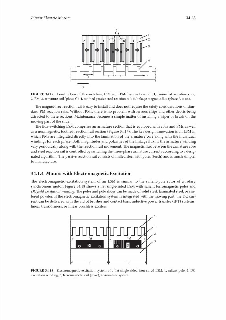
8102019 Power Handbook
httpslidepdfcomreaderfullpower-handbook 2943
34-14 Electric Power Generation Transmission and Distribution
LSMs with electromagnetic excitation (wound-1047297eld reaction rail) are used in German ransrapid
maglev train (Figure 3419)
3415 Motors with Superconducting Excitation System
In large-power LSMs the electromagnets with erromagnetic core that produce the excitation 1047298ux can
be replaced by coreless SC electromagnets Since the magnetic 1047298ux density produced by the SC electro-
magnet is greater than the saturation magnetic 1047298ux density o the best laminated alloys ( Bsat asymp 24 or
cobalt alloy) there is no need to use the armature erromagnetic core An LSM with SC 1047297eld excitation
system is a totally air-cored machine (Figure 3420)
Experimental maglev trains on the Yamanashi Maglev est Line (YML) in Yamanashi Preecture(west rom okyo) Japan are driven by air-cored LSMs with SC excitation systems ( Figure 3421)
342 Linear Induction Motors
LIMs have ound the widest prospects or applications in transportation systems beginning with electri-
cal traction on small passenger or material supply cars (used at airports exhibitions electrohighways
elevators) and ending with pallet transportation waer transportation belt conveyors transportation
systems o bulk materials etc Te second important place or LIM applications is in industry ie man-
uacturing processes (machine tools hammers presses mills separators automated manuacturing systems
strip tensioners textile shuttles index tables turntables disk saws or wood sliding doors robots etc)
ransrapid 09 maglev train driven by LSMs with electromagnetic excitation (Photo courtesy oTyssen ransrapid System GmbH Munich Germany)
1
2A
B
C B
A
A
C
S SN
τ τ τ τ τ
N N
CBA
Tree-phase air-cored LSM with SC excitation system 1 armature coils 2 SC excitation coils
8102019 Power Handbook
httpslidepdfcomreaderfullpower-handbook 3043
34-15Linear Electric Motors
LIMs can also play an important part in industrial investigations and tests or example high acceleration
o model aircraf in aerodynamic tunnels high acceleration o vessels in laboratory pools propulsion o
mixers shakers and vibrators and adjusting xndashy tables and instruments Tere is also a possibility o
using LIMs in consumer electronics (sound and vision equipment knitting machines curtains) and in
offices (transportation o documents letters and cash) Te Handbook o Linear Motor Applications [21]
printed in Japan in 1986 contains about 50 examples o applications o LIMs in operation or in the pro-
cess o implementation
3421 Basic Geometries and Constructions
A LIM can be obtained by cutting in the same way either a cage rotor induction motor or a wound rotor
induction motor Te stator becomes the primary and the rotor becomes the secondary [12] Te secondary
o a LIM can be simpli1047297ed by using a solid steel core and replacing the cage (ladder) or slip-ring winding with
a high-conductivity nonerromagnetic plate (Al or Cu) Te nonerromagnetic plate is a secondary electric
circuit with distributed parameters and the erromagnetic core is a conductor both or the magnetic 1047298ux
and the electric current It does not matter rom the principle o operation point o view which part (primary
or secondary) is in motion Tus the 1047298at single-sided LIM can be obtained rom a solid rotor induction
motor (Figure 341a) and the 1047298at double-sided LIM can be obtained rom a hollow-rotor induction motor
with wound external and internal stator (Figure 341b) In a double-sided LIM the secondary erromagneticcore is not necessary since the magnetic 1047298ux excited by one o the primary windings afer passing through
the air gaps and nonerromagnetic secondary is then closed up by the core o the second primary unit
Teoretically a double-sided LIM with primary windings located on two cores in comparison with a
single-sided LIM exciting the same MMF has twice the air gap magnetic 1047298ux density Tereore the thrust
o such a motor is our times greater assuming the same dimensions I only one primary core is wound
the output parameters o a double-sided LIM are the same as those or a single-sided LIM with laminated
secondary back iron Te undamental advantage o double-sided LIMs is the elimination o the normal
attractive orce between the primary and the secondary because the secondary is usually nonerromagnetic
Flat LIMs can have primary cores consisting o an array o cores arranged in parallel at appropri-
ate distances and connected magnetically by additional yokes perpendicular to the direction o the
YML in Yamanashi Preecture (near okyo) Japan YML maglev trains use air-cored LSMs
with SC excitation system (Photo courtesy o Central Japan Railway Company and Railway echnical Research
Institute okyo Japan)
8102019 Power Handbook
httpslidepdfcomreaderfullpower-handbook 3143
34-16 Electric Power Generation Transmission and Distribution
traveling 1047297eld A magnetic circuit designed in such a way makes it possible to apply two windings in
general multiphase windings with perpendicular conductors as shown in Figure 3422 Adjusting the
current in each winding the secondary can be moved in two perpendicular directions and can be posi-
tioned at any point o the xndashy plane A 1047298at LIM with two degrees o reedom (DOFs) can be designed both
as single-sided and double-sided machines
By rolling a 1047298at single-sided or double-sided LIM around the axis parallel to the direction o the travel-
ing magnetic 1047297eld ie parallel to the direction o the thrust a tubular motor can be obtained (Figure 3423)
A tubular (cylindrical) LIM similar to a 1047298at LIM can be designed both as single-sided and double-
sided machines and can have a square or rectangular cross section as in Figure 3424 Tere are possible
Te primary o a 1047298at LIM with two DOFs
g
g
g 1
g 2
(c)
(b)
(a)
d
v
v
v
1
1
1 1
1
1
2
2
2
2
2
2
ubular LIMs (a) single-sided with an external short primary (b) single-sided with an external
short secondary and (c) double-sided with short primary 1 primary 2 secondary
8102019 Power Handbook
httpslidepdfcomreaderfullpower-handbook 3243
34-17Linear Electric Motors
con1047297gurations other than that in Figure 3423 regarding the length o the secondary with respect to thelength o the primary
All the aorementioned LIMs are motors with longitudinal magnetic 1047298ux ie the lines o magnetic
1047298ux lie in the plane parallel to the direction o the traveling magnetic 1047297eld A LIM can also be designed
in such a way as to obtain magnetic 1047298ux lines perpendicular to the direction o the traveling 1047297eld Such
motors are said to have transverse magnetic 1047298ux (Figure 3425)
Te undamental advantage o a LIM with transverse magnetic 1047298ux in comparison with a LIM with
longitudinal magnetic 1047298ux is the lower magnetizing current necessary due to the shorter magnetic 1047298ux
paths Te signi1047297cant disadvantage is lower thrust A 1047298at LIM with transverse magnetic 1047298ux usually has
a primary winding o concentrated coils located on salient poles
A 1047298at single-sided LIM with transverse 1047298ux can produce not only thrust but also electrodynamic
suspension In the design shown in Figure 3426 the secondary is suspended electrodynamically andpropelled and stabilized laterally by the primary magnetic 1047297eld [8] Te primary magnetic circuit con-
sists o E-shaped laminations assembled in two rows Te short secondary is made o light Al alloy in the
orm o a boat Te lateral sides o the boat are inclined by 60deg with respect to the active surace Such a
shape provides maximum normal repulsive orce and maximum lateral stabilization
According to their geometry the LIMs can be divided into the ollowing groups
bull With movable primary or movable secondary
bull Single sided and double sided
bull Flat and tubular
bull With short primary and short secondary
bull With longitudinal and transverse magnetic 1047298ux
1 2 3 4 1 2 3 4
ubular double-sided LIM with a square cross section 1 primary 2 secondary 3 primary coil
4 internal core
v
v
1 1
1
1
(a)
(b)
22
22
Flat LIM with transverse magnetic 1047298ux and salient poles (a) single-sided and (b) double-sided
1 primary 2 secondary
8102019 Power Handbook
httpslidepdfcomreaderfullpower-handbook 3343
34-18 Electric Power Generation Transmission and Distribution
Te linear speed o a LIM is
v s v s= minus( )1 (346)
where
s is the slip
v s is the synchronous speed according to Equation 341
Neglecting the longitudinal end effect [6] the electromagnetic thrust developed by a LIM can be
expressed in a similar way as or a rotary induction motor ie
F
m
v I
R
sdx
s
= prime( ) prime1
2
2 2
(347)
where
m1 is the number o phases o the primary winding
v s is the synchronous speed according to Equation 341
primeI 2 is the secondary current reerred to the primary system
primeR2 is the secondary resistance reerred to the primary system
s is the slip
Te secondary resistance primeR2 must include the so-called edge effect [6]
3422 Propulsion of Wheel-on-Rail Vehicles
Modern railway systems and electrical traction should meet the ollowing requirements
bull High level o automatization and computerization
bull Propulsion and braking independent o adhesion which in turn is affected 1047297rst o all by climate
and weather
bull Low level o noise sometimes below 70 dB (A)
Flat LIM with transverse magnetic 1047298ux salient poles and nonerromagnetic secondary pro-
pelled suspended and stabilized electrodynamically (From Gieras JF et al Analytical calculation o electro-
dynamic levitation orces in a special-purpose linear induction motor International Electric Machines and Drives
Conerence (IEMDCrsquo11) Niagara Falls Ontario Canada 2011 [on CD-ROM])
8102019 Power Handbook
httpslidepdfcomreaderfullpower-handbook 3443
34-19Linear Electric Motors
bull Ability to cope with high slopes at least 6 and sharp bends with radius o curvature less than 20 m
bull No pollution to natural environment and landscape
bull High reliability
Te congestion problems o big cities should be solved by creating collective transport orms that can be
implemented without affecting a highly populated city For example there are many cities in Italy where
the historical center has remained the same since the Renaissance A heavy railway might be a com-
pletely wrong solution and have a notable impact on the city planning An adequate solution might be
a light railway a people mover with transport capacity o 10000ndash20000 passengers per hour to replace
the traditional transport nets and to integrate the existing railway nets
All the requirements mentioned earlier can be met by using LIMs as propulsion machines Replacing
electrical rotary motors with linear motors in traction drives (electrical locomotives) generally does
not require new tracks but only their adjustment to linear drives Single-sided LIMs (Figure 3427a and b)
are best since the normal attractive orce o these can strengthen the adhesion o wheels and rails
Te air gap is rom 10 to 15 mm Most requently the motor car has two LIMs with short primaries
(Figure 3427a) assembled in series Te double-layer secondary consists o a solid back iron and an Al
cap and is located between the rails Cables or computer communication with the vehicle and quite
ofen collectors or electrical energy delivery to the vehicle are located along the track Tree-phaseLIMs are ed rom variable-voltage variable-requency (VVVF) voltage-source inverters A linear pro-
pulsion system o wheel-on-rail vehicles allows more 1047298exibility (Figure 3428) reducing noise on bends
and wear o the wheels and rails
Double-sided LIMs (Figure 3427c and d) have ound very limited application due to the technical
difficulty o eliminating aults caused by bends in the secondary with primary cores on either side It is
more difficult to keep a small and uniorm air gap in double-sided LIMs than that in single-sided LIMs
Te LIM-driven wheel-on-rail vehicles are built or low velocities ie less than 100 kmh and or
short routes ie less than 50 km (urban transit systems and short-distance trains) At present LIM-
driven trains operate in oronto and Vancouver BC Canada in Detroit MI (Figure 3429) okyo
(Figure 3430) and Osaka Japan and Kuala Lumpur Malaysia
(a) (b)
(c) (d)
LIM-driven wheel-on-rail cars (a) single-sided LIM with short primary mounted on the undercar-
riage (b) single-sided LIM with short secondary mounted on the undercarriage (c) double-sided LIM with short pri-
mary mounted on the undercarriage and (d) double-sided LIM with short secondary mounted on the undercarriage
8102019 Power Handbook
httpslidepdfcomreaderfullpower-handbook 3543
34-20 Electric Power Generation Transmission and Distribution
(a) (b)
Te undercarriage o a wheel-on-rail vehicle (a) rotary motor propulsion and (b) LIM propulsion
Detroit people mover driven by single-sided LIMs
oei Oedo subway line in okyo driven by single-sided LIMs
8102019 Power Handbook
httpslidepdfcomreaderfullpower-handbook 3643
34-21Linear Electric Motors
Te design data o some single-sided traction LIMs are presented in able 347 and double-sided trac-
tion LIMs in able 348
343 Variable Reluctance Motors
Te simplest construction o a variable reluctance LSM or linear reluctance motor (LRM) is that shown
in Figure 3418 with DC excitation winding being removed However the thrust o such a motor wouldbe low as the ratio o d -axis permeance to q-axis permeance is low Better perormance can be obtained
when using 1047298ux barriers [18] or steel laminations [15] o make 1047298ux barriers any nonerromagnetic
materials can be used o obtain high permeance (low reluctance) in the d -axis and low permeance in
the q-axis steel laminations should be oriented in such a way as to create high permeance or the d -axis
magnetic 1047298ux
Figure 3431a shows a variable reluctance platen with 1047298ux barriers and Figure 3431b shows how to
arrange steel laminations to obtain different reluctances in the d - and q-axes Te platen can be com-
posed o segments the length o which is equal to the pole pitchτ Each segment consists o semicircular
lamellas cut out rom electrotechnical sheet A 1047297lling or example epoxy resin is used to make the seg-
ment rigid and robust By putting the segments together a platen o any desired length can be obtained
Design Data o Single-Sided Tree-Phase LIMs or Propulsion o Vehicles
Quantity
LIM
UnitJLMDR ICS KU CIGG GEC
Pullout thrust at requency given
in the ollowing F x
125 90 35 17 07 kN
Input requency 200 400 250 400 600 Hz
Rated phase current V 1 2750 4650 1300 2000 2000 A
Number o poles 2 p 8 6 4 6 4 mdash
Number o turns per phase N 1 128 96 128 108 48 mdash
Equivalent diameter o conductor d 1 mdash 893 528 1115 81 mm
Number o parallel conductors mdash 1 mdash 19 1 mdash
Effective width o primary core Li 023 0216 029 0101 01715 m
Pole pitch τ 027 02868 030 025 020 m
Length o single end connection l e mdash 03483 mdash 02955 03685 m
Coil pitch wc 0225 01673 025 01944 01555 m
Air gap g 150 126 120 150 182 mm
Number o slots z 1( primez 1) 96(106) 72(79) 48(58) 54(61) 36(43) mdash
Width o slot b11 mdash 156 170 150 1308 mm
Width o slot opening b14 mdash 156 mdash 1044 1308 mm
Depth o slot h11 mdash 530 380 3421 6147 mm
Height o yoke h1 y mdash 436 393 7163 500 mm
Conductivity o back iron at 20degC σFe mdash 446 952 446 512 times106 Sm
Conductivity o Al cap at 20degC σ Al mdash 300 303 323 215 times106 Sm
Width o back iron w 03 024 03 0111 01715 m
Tickness o back iron hsec 190 125 250 254 474 mm
Tickness o Al cap d 50 45 50 45(25) 32 mm
Tickness o Al cap behind Fe core t ov 50 170 50 127 32 mm
Width o Al cap 030 032 040 0201 02985 m
JLMDR Japanese Linear Motor Driven Railcar Japan ICS Intermediate Capacity ransit System Canada KU
Kyushu University LIM Japan CIGG Canadian Inst o Guided Ground ransport Canada GEC General
Electric Company United States (z 1 ) is the number o hal 1047297lled slots
8102019 Power Handbook
httpslidepdfcomreaderfullpower-handbook 3743
34-22 Electric Power Generation Transmission and Distribution
344 Stepping Motors
A linear stepping motor has a concentrated armature winding wound on salient poles and PM excitation
rail or variable reluctance platen Te thrust is generated as an action o the armature magnetic 1047298ux and
PM 1047298ux (active platen) or the armature magnetic 1047298ux and salient erromagnetic poles (variable reluc-
tance platen) Stepping motors have no position eedback
Design Data o Double-Sided Tree-Phase LIMs or Propulsion
o Vehicles
Quantity
LIM
UnitGEC LIMVR
Maximum thrust at input requency F x given in the ollowing 085 1668 kN
Input requency 600 1730 Hz
Input phase current I 1 2000 20000 A
Number o poles 2 p 4 10 mdash
Number o turns per phase N 1 144 100 mdash
Diameter o conductor d 1 075 110 mm
Effective width o primary core Li 00869 0254 m
Pole pitch τ 01795 03556 m
Coil pitch wc 005 005 m
Number o slots z 1( primez 1) 36(45) 150(160) mdash
Width o slot b11 137 160 mm
Width o slot opening b14 137 mdash mm
Depth o slot h1 630 mdash mm
Height o yoke h1 y 239 mdash mm
Width o tooth c1 200 77 mm
Resultant air gap 2 g + d 381 38075 mm
Air gap g 2 times 127 2 times 111 mm
Tickness o secondary d 127 15875(hollow) mm
Effective thickness o Al secondary 127 72 mm
Width o secondary w ge03046 mdash m
Conductivity o Al cap at 20degC σ Al asymp2434 asymp240 times106 Sm
GEC General Electric Company United States LIMVR LIM Research Vehicle
Pueblo CO United States (z 1 ) is the number o hal 1047297lled slots
(a) (b)
q q d d d q d q d d
Laminations
τ τ τ τ
Epoxy resin
Variable reluctance LSMs with (a) 1047298ux barriers and (b) steel laminations
8102019 Power Handbook
httpslidepdfcomreaderfullpower-handbook 3843
8102019 Power Handbook
httpslidepdfcomreaderfullpower-handbook 3943
34-24 Electric Power Generation Transmission and Distribution
Tis value is different or ull-step and microstepping drives Te maximum startndashstop speed is the
maximum speed that can be used when starting or stopping the motor without ramping that does not
cause the motor to all out o synchronism or lose steps Te maximum speed is the maximum linear
speed that can be achieved without the motor stalling or alling out o synchronism Te maximum
load mass is the maximum allowable mass applied to the orcer against the scale that does not result in
mechanical damage Te ull-step resolution is the position increment obtained when the currents are
switched rom one winding to the next winding Tis is the typical resolution obtained with ul l-step
drives and it is strictly a unction o the motor construction Te microstepping resolution is the position
increment obtained when the ull-step resolution is divided electronically by proportioning the currents
in the two windings Tis resolution is typically 10ndash250 times smaller than the ull-step resolution [13]
HLSMs are regarded as an excellent solution to positioning systems that require a high accuracy
and rapid acceleration With a microprocessor controlled microstepping mode a smooth operation with
standard resolution o a ew hundred stepsmm can be obtained Te advantages such as high efficiencyhigh throughput mechanical simplicity high reliability precise open-loop operation and low inertia
o the system have made these kind o motors more and more attractive in such applications as actory
automation high speed positioning computer peripherals acsimile machines numerically controlled
machine tools automated medical equipment automated laboratory equipment and welding robots
Tis motor is especially suitable or machine tools printers plotters and computer-controlled material
handling in which a high positioning accuracy and repeatability are the key problems
When two or our orcers mounted at 90deg and a special grooved platen (ldquowaffle platerdquo) are used the
xndashy motion (two DOFs) in a single plane is obtained (Figure 3434)
Speci1047297cation data o the xndashy HLSMs manuactured by Normag Northern Magnetics Inc Santa
Clarita CA are given in able 3410
PM linear stepping motors (Photo courtesy o okyo Aircraf Instrument Co Ltd okyo Japan)
8102019 Power Handbook
httpslidepdfcomreaderfullpower-handbook 4043
34-25Linear Electric Motors
345 Switched Reluctance Motors
Te topology o a linear switched reluctance motor is similar to that o a stepping motor with variable
reluctance platen In addition it is equipped with position sensors Te turn-on and turn-off instant o
the input current is synchronized with the position o the moving part Te thrust is very sensitive to
the turn-on and turn-off instant
In the case o a linear stepping or linear switched reluctance motor the speed v o the moving part is
v v s sw= = τ
(348)
where
sw is the undamental switching requency in one armature phase winding
τ is the pole pitch o the reaction rail
For a rotary stepping or switched reluctance motor sw = 2 pr n where 2 pr is the number o rotor poles and
n is rotational speed in revs
A linear switched reluctance motor has a doubly salient magnetic circuit with a polyphase winding
on the armature Longitudinal and transverse 1047298ux designs are shown in Figure 3435 A linear switched
reluctance motor allows precise speed and position-controlled linear motion at low speeds and is not sub-
ject to design constraints (minimum speed limited by minimum easible pole pitch) o linear AC motors
x
y
12
3
4
1
1
2
2
HLSM with a our-unit orcer to obtain the xndashy motion 1 orcers or the x -direction 2 orcers
or the y -direction 3 platen 4 air pressure
Data o xndashy HLSMs Manuactured by Normag Northern Magnetics Inc
Santa Clarita CA
Parameter 4XY0602-2-0 4XY2002-2-0 4XY2004-2-0 4XY2504-2-0
Number o orcer units per axis 1 1 2 2
Number o phases 2 2 2(4) 2(4)Static thrust N 133 400 980 1330
Trust at 1 ms N 111 311 712 980
Normal attractive orce N 1600 4000 14400 18000
Resistance per phase Ω 29 33 16 19
Inductance per phase mH 15 40 20 23
Input phase current A 20 20 40 40
Air gap mm 002
Maximum temperature degC 110
Mass kg 32 072 20 15
Repeatability mm 000254
Resolution mm 000254
Bearing type Air
8102019 Power Handbook
httpslidepdfcomreaderfullpower-handbook 4143
34-26 Electric Power Generation Transmission and Distribution
346 Linear Positioning Stages
Linear motors are now playing a key role in advanced precision linear positioning Linear precision posi-
tioning systems can be classi1047297ed into open-loop systems with HLSMs and closed-loop servo systems
with LSMs LBMs or LIMs
A PM LSMndashdriven positioning stage is shown in Figure 3436 A stationary base is made o Al steel
ceramic or granite plate It provides a stable precise and 1047298at platorm to which all stationary position-
ing components are attached Te base o the stage is attached to the host system with the aid o mount-
ing screws
Te moving table accommodates all moving positioning components o achieve maximum accelera-
tion the mass o the moving table should be as small as possible and usually Al is used as a lightweight
material A number o mounting holes on the moving table is necessary to 1047297x the payload to the mount-
ing table
Linear bearing rails provide a precise guidance to the moving table A minimum o one bearing rail
is required Linear ball bearing or air bearings are attached to each rail
Te armature o a linear motor is astened to the moving table and reaction rail (PM excitation sys-tem) is built in the base between the rails (Figure 3436)
A linear encoder is needed to obtain precise control o position o the table velocity and acceleration
Te read head o the encoder is attached to the moving table
(a) (b)
3
3
221
1
Linear switched reluctance motor con1047297gurations (a) longitudinal 1047298ux design and (b) transverse
1047298ux design 1 armature winding 2 armature stack 3 platen
12
3
5
4
7
6
8
Linear positioning stage driven by PM LBM 1 base 2 moving table 3 armature o LBM 4 PMs
5 linear bearing 6 encoder 7 cable carrier 8 limit switch (Courtesy o Normag Santa Clarita CA)
8102019 Power Handbook
httpslidepdfcomreaderfullpower-handbook 4243
34-27Linear Electric Motors
Noncontact limit switches ixed to the base provide an overtravel protection and init ial homing
A cable carrier accommodates and routes electrical cables between the moving table and stationary
connector box 1047297xed to the base
An HLSM-driven linear precision stage is o similar construction Instead o PMs between bearing
rails it has a variable reluctance platen HLSMs usually need air bearings and in addition to the electri-
cal cables an air hose between air bearings and the compressor is requiredLinear positioning stages are used in semiconductor technology electronic assembly quality assur-
ance laser cutting optical scanning water jet cutting gantry systems (x y z stages) color printers
plotters and Cartesian coordinate robotics
References
1 Anorad Linear Motors Inormation Brochure Anorad Hauppauge New York 2007 wwwanoradcom
2 Boldea I and Nasar SA Linear Motion Electromagnetic Systems John Wiley amp Sons New York 1985
3 Boldea I and Nasar SA Linear Electric Actuators and Generators Cambridge University Press
New York 2005
4 Compumotor Digiplan Positioning Control Systems and Drives Parker Hanni1047297n CorporationRohnert Park CA 2011
5 Everes W Henneberger G Wunderlich H and Selig A A linear homopolar motor or a trans-
portation system 2nd International Symposium on Linear Drives or Industry Applications (LDIArsquo98)
okyo Japan 1998 pp 46ndash49
6 Gieras JF Linear Induction Drives Clarendon Press Oxord UK 1994
7 Gieras JF Status o linear motors in the United States International Symposium on Linear Drives
or Industry Applications (LDIArsquo03) Birmingham UK 2003 pp 169ndash176
8 Gieras JF Gientkowski Z Mews J and Splawski P Analytical calculation o electrodynamic
levitation orces in a special-purpose linear induction motor International Electric Machines and
Drives Conerence (IEMDCrsquo11) Niagara Falls Ontario Canada 2011 [on CD-ROM]
9 Gieras JF Piech ZJ and omczuk BZ Linear Synchronous Motors ransportation and Automation Systems aylor amp Francis (CRC Press) Boca Raton FL 2011
10 Hoang E Ahmed AHB and Lucidarme J Switching 1047298ux permanent magnet polyphase syn-
chronous machines 7th European Conerence on Power Electronics and Applications (EPErsquo97)
Vol 3 rondheim Norway 1977 pp 903ndash908
11 Kollmorgen Linear Motors Aim to Cut Cost o Semiconductors and Electronics Manuacture
Kollmorgen Radord VA 1997
12 Laithwaite ER A History o Linear Electric Motors Macmillan London UK 1987
13 Linear Step Motor Inormation Brochure okyo Aircraf Instrument Co Ltd okyo Japan
1998
14 LinMot Design Manual Sulzer Electronics Ltd Zuumlrich Switzerland 1999
15 Locci N and Marongiu I Modelling and testing a new linear reluctance motor InternationalConerence on Electrical Machines (ICEMrsquo92) Vol 2 Manchester UK 1992 pp 706ndash710
16 Rauch SE and Johnson LJ Design principles o 1047298ux-switch alternators AIEE rans Part III
74(12) 1261ndash1269 1955
17 Rosenmayr M Casat Glavitsch A and Stemmler H SwissmetromdashPower supply or a high-
power-propulsion system with short stator linear motors 15th International Conerence on
Magnetically Levitated Systems and Linear Drives Maglevrsquo98 Mount Fuji Yamanashi Japan 1998
pp 280ndash286
18 Sanada M Morimoto S and akeda Y Reluctance equalization design o multi 1047298ux barrier con-
struction or linear synchronous reluctance motors 2nd International Symposium on Linear Drives
or Industrial Applications (LDIArsquo98) okyo Japan 1998 pp 259ndash262
8102019 Power Handbook
httpslidepdfcomreaderfullpower-handbook 4343
34-28 Electric Power Generation Transmission and Distribution
19 Seok-Myeong J and Sang-Sub J Design and analysis o the linear homopolar synchronous motor
or integrated magnetic propulsion and suspension 2nd International Symposium on Linear Drives
or Industrial Applications (LDIArsquo98) okyo Japan 1998 pp 74ndash77
20 Synchronous Linear Motor 1FN6 Te Electrical Gear Rack Siemens AG Industry Sector Drive
echnologies Motion Control Erlangen Germany 2008
21 Yamada H Handbook o Linear Motor Applications (in Japanese) Kogyo Chosaki Publishing Cookyo Japan 1986
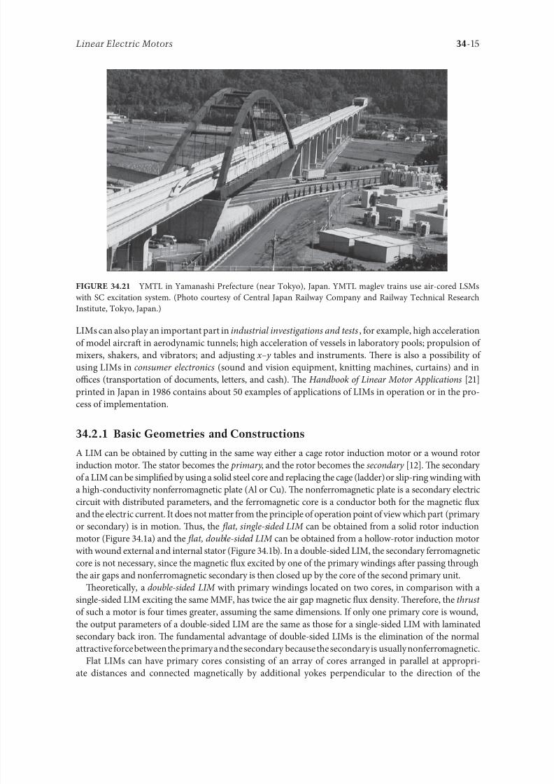
8102019 Power Handbook
httpslidepdfcomreaderfullpower-handbook 3043
34-15Linear Electric Motors
LIMs can also play an important part in industrial investigations and tests or example high acceleration
o model aircraf in aerodynamic tunnels high acceleration o vessels in laboratory pools propulsion o
mixers shakers and vibrators and adjusting xndashy tables and instruments Tere is also a possibility o
using LIMs in consumer electronics (sound and vision equipment knitting machines curtains) and in
offices (transportation o documents letters and cash) Te Handbook o Linear Motor Applications [21]
printed in Japan in 1986 contains about 50 examples o applications o LIMs in operation or in the pro-
cess o implementation
3421 Basic Geometries and Constructions
A LIM can be obtained by cutting in the same way either a cage rotor induction motor or a wound rotor
induction motor Te stator becomes the primary and the rotor becomes the secondary [12] Te secondary
o a LIM can be simpli1047297ed by using a solid steel core and replacing the cage (ladder) or slip-ring winding with
a high-conductivity nonerromagnetic plate (Al or Cu) Te nonerromagnetic plate is a secondary electric
circuit with distributed parameters and the erromagnetic core is a conductor both or the magnetic 1047298ux
and the electric current It does not matter rom the principle o operation point o view which part (primary
or secondary) is in motion Tus the 1047298at single-sided LIM can be obtained rom a solid rotor induction
motor (Figure 341a) and the 1047298at double-sided LIM can be obtained rom a hollow-rotor induction motor
with wound external and internal stator (Figure 341b) In a double-sided LIM the secondary erromagneticcore is not necessary since the magnetic 1047298ux excited by one o the primary windings afer passing through
the air gaps and nonerromagnetic secondary is then closed up by the core o the second primary unit
Teoretically a double-sided LIM with primary windings located on two cores in comparison with a
single-sided LIM exciting the same MMF has twice the air gap magnetic 1047298ux density Tereore the thrust
o such a motor is our times greater assuming the same dimensions I only one primary core is wound
the output parameters o a double-sided LIM are the same as those or a single-sided LIM with laminated
secondary back iron Te undamental advantage o double-sided LIMs is the elimination o the normal
attractive orce between the primary and the secondary because the secondary is usually nonerromagnetic
Flat LIMs can have primary cores consisting o an array o cores arranged in parallel at appropri-
ate distances and connected magnetically by additional yokes perpendicular to the direction o the
YML in Yamanashi Preecture (near okyo) Japan YML maglev trains use air-cored LSMs
with SC excitation system (Photo courtesy o Central Japan Railway Company and Railway echnical Research
Institute okyo Japan)
8102019 Power Handbook
httpslidepdfcomreaderfullpower-handbook 3143
34-16 Electric Power Generation Transmission and Distribution
traveling 1047297eld A magnetic circuit designed in such a way makes it possible to apply two windings in
general multiphase windings with perpendicular conductors as shown in Figure 3422 Adjusting the
current in each winding the secondary can be moved in two perpendicular directions and can be posi-
tioned at any point o the xndashy plane A 1047298at LIM with two degrees o reedom (DOFs) can be designed both
as single-sided and double-sided machines
By rolling a 1047298at single-sided or double-sided LIM around the axis parallel to the direction o the travel-
ing magnetic 1047297eld ie parallel to the direction o the thrust a tubular motor can be obtained (Figure 3423)
A tubular (cylindrical) LIM similar to a 1047298at LIM can be designed both as single-sided and double-
sided machines and can have a square or rectangular cross section as in Figure 3424 Tere are possible
Te primary o a 1047298at LIM with two DOFs
g
g
g 1
g 2
(c)
(b)
(a)
d
v
v
v
1
1
1 1
1
1
2
2
2
2
2
2
ubular LIMs (a) single-sided with an external short primary (b) single-sided with an external
short secondary and (c) double-sided with short primary 1 primary 2 secondary
8102019 Power Handbook
httpslidepdfcomreaderfullpower-handbook 3243
34-17Linear Electric Motors
con1047297gurations other than that in Figure 3423 regarding the length o the secondary with respect to thelength o the primary
All the aorementioned LIMs are motors with longitudinal magnetic 1047298ux ie the lines o magnetic
1047298ux lie in the plane parallel to the direction o the traveling magnetic 1047297eld A LIM can also be designed
in such a way as to obtain magnetic 1047298ux lines perpendicular to the direction o the traveling 1047297eld Such
motors are said to have transverse magnetic 1047298ux (Figure 3425)
Te undamental advantage o a LIM with transverse magnetic 1047298ux in comparison with a LIM with
longitudinal magnetic 1047298ux is the lower magnetizing current necessary due to the shorter magnetic 1047298ux
paths Te signi1047297cant disadvantage is lower thrust A 1047298at LIM with transverse magnetic 1047298ux usually has
a primary winding o concentrated coils located on salient poles
A 1047298at single-sided LIM with transverse 1047298ux can produce not only thrust but also electrodynamic
suspension In the design shown in Figure 3426 the secondary is suspended electrodynamically andpropelled and stabilized laterally by the primary magnetic 1047297eld [8] Te primary magnetic circuit con-
sists o E-shaped laminations assembled in two rows Te short secondary is made o light Al alloy in the
orm o a boat Te lateral sides o the boat are inclined by 60deg with respect to the active surace Such a
shape provides maximum normal repulsive orce and maximum lateral stabilization
According to their geometry the LIMs can be divided into the ollowing groups
bull With movable primary or movable secondary
bull Single sided and double sided
bull Flat and tubular
bull With short primary and short secondary
bull With longitudinal and transverse magnetic 1047298ux
1 2 3 4 1 2 3 4
ubular double-sided LIM with a square cross section 1 primary 2 secondary 3 primary coil
4 internal core
v
v
1 1
1
1
(a)
(b)
22
22
Flat LIM with transverse magnetic 1047298ux and salient poles (a) single-sided and (b) double-sided
1 primary 2 secondary
8102019 Power Handbook
httpslidepdfcomreaderfullpower-handbook 3343
34-18 Electric Power Generation Transmission and Distribution
Te linear speed o a LIM is
v s v s= minus( )1 (346)
where
s is the slip
v s is the synchronous speed according to Equation 341
Neglecting the longitudinal end effect [6] the electromagnetic thrust developed by a LIM can be
expressed in a similar way as or a rotary induction motor ie
F
m
v I
R
sdx
s
= prime( ) prime1
2
2 2
(347)
where
m1 is the number o phases o the primary winding
v s is the synchronous speed according to Equation 341
primeI 2 is the secondary current reerred to the primary system
primeR2 is the secondary resistance reerred to the primary system
s is the slip
Te secondary resistance primeR2 must include the so-called edge effect [6]
3422 Propulsion of Wheel-on-Rail Vehicles
Modern railway systems and electrical traction should meet the ollowing requirements
bull High level o automatization and computerization
bull Propulsion and braking independent o adhesion which in turn is affected 1047297rst o all by climate
and weather
bull Low level o noise sometimes below 70 dB (A)
Flat LIM with transverse magnetic 1047298ux salient poles and nonerromagnetic secondary pro-
pelled suspended and stabilized electrodynamically (From Gieras JF et al Analytical calculation o electro-
dynamic levitation orces in a special-purpose linear induction motor International Electric Machines and Drives
Conerence (IEMDCrsquo11) Niagara Falls Ontario Canada 2011 [on CD-ROM])
8102019 Power Handbook
httpslidepdfcomreaderfullpower-handbook 3443
34-19Linear Electric Motors
bull Ability to cope with high slopes at least 6 and sharp bends with radius o curvature less than 20 m
bull No pollution to natural environment and landscape
bull High reliability
Te congestion problems o big cities should be solved by creating collective transport orms that can be
implemented without affecting a highly populated city For example there are many cities in Italy where
the historical center has remained the same since the Renaissance A heavy railway might be a com-
pletely wrong solution and have a notable impact on the city planning An adequate solution might be
a light railway a people mover with transport capacity o 10000ndash20000 passengers per hour to replace
the traditional transport nets and to integrate the existing railway nets
All the requirements mentioned earlier can be met by using LIMs as propulsion machines Replacing
electrical rotary motors with linear motors in traction drives (electrical locomotives) generally does
not require new tracks but only their adjustment to linear drives Single-sided LIMs (Figure 3427a and b)
are best since the normal attractive orce o these can strengthen the adhesion o wheels and rails
Te air gap is rom 10 to 15 mm Most requently the motor car has two LIMs with short primaries
(Figure 3427a) assembled in series Te double-layer secondary consists o a solid back iron and an Al
cap and is located between the rails Cables or computer communication with the vehicle and quite
ofen collectors or electrical energy delivery to the vehicle are located along the track Tree-phaseLIMs are ed rom variable-voltage variable-requency (VVVF) voltage-source inverters A linear pro-
pulsion system o wheel-on-rail vehicles allows more 1047298exibility (Figure 3428) reducing noise on bends
and wear o the wheels and rails
Double-sided LIMs (Figure 3427c and d) have ound very limited application due to the technical
difficulty o eliminating aults caused by bends in the secondary with primary cores on either side It is
more difficult to keep a small and uniorm air gap in double-sided LIMs than that in single-sided LIMs
Te LIM-driven wheel-on-rail vehicles are built or low velocities ie less than 100 kmh and or
short routes ie less than 50 km (urban transit systems and short-distance trains) At present LIM-
driven trains operate in oronto and Vancouver BC Canada in Detroit MI (Figure 3429) okyo
(Figure 3430) and Osaka Japan and Kuala Lumpur Malaysia
(a) (b)
(c) (d)
LIM-driven wheel-on-rail cars (a) single-sided LIM with short primary mounted on the undercar-
riage (b) single-sided LIM with short secondary mounted on the undercarriage (c) double-sided LIM with short pri-
mary mounted on the undercarriage and (d) double-sided LIM with short secondary mounted on the undercarriage
8102019 Power Handbook
httpslidepdfcomreaderfullpower-handbook 3543
34-20 Electric Power Generation Transmission and Distribution
(a) (b)
Te undercarriage o a wheel-on-rail vehicle (a) rotary motor propulsion and (b) LIM propulsion
Detroit people mover driven by single-sided LIMs
oei Oedo subway line in okyo driven by single-sided LIMs
8102019 Power Handbook
httpslidepdfcomreaderfullpower-handbook 3643
34-21Linear Electric Motors
Te design data o some single-sided traction LIMs are presented in able 347 and double-sided trac-
tion LIMs in able 348
343 Variable Reluctance Motors
Te simplest construction o a variable reluctance LSM or linear reluctance motor (LRM) is that shown
in Figure 3418 with DC excitation winding being removed However the thrust o such a motor wouldbe low as the ratio o d -axis permeance to q-axis permeance is low Better perormance can be obtained
when using 1047298ux barriers [18] or steel laminations [15] o make 1047298ux barriers any nonerromagnetic
materials can be used o obtain high permeance (low reluctance) in the d -axis and low permeance in
the q-axis steel laminations should be oriented in such a way as to create high permeance or the d -axis
magnetic 1047298ux
Figure 3431a shows a variable reluctance platen with 1047298ux barriers and Figure 3431b shows how to
arrange steel laminations to obtain different reluctances in the d - and q-axes Te platen can be com-
posed o segments the length o which is equal to the pole pitchτ Each segment consists o semicircular
lamellas cut out rom electrotechnical sheet A 1047297lling or example epoxy resin is used to make the seg-
ment rigid and robust By putting the segments together a platen o any desired length can be obtained
Design Data o Single-Sided Tree-Phase LIMs or Propulsion o Vehicles
Quantity
LIM
UnitJLMDR ICS KU CIGG GEC
Pullout thrust at requency given
in the ollowing F x
125 90 35 17 07 kN
Input requency 200 400 250 400 600 Hz
Rated phase current V 1 2750 4650 1300 2000 2000 A
Number o poles 2 p 8 6 4 6 4 mdash
Number o turns per phase N 1 128 96 128 108 48 mdash
Equivalent diameter o conductor d 1 mdash 893 528 1115 81 mm
Number o parallel conductors mdash 1 mdash 19 1 mdash
Effective width o primary core Li 023 0216 029 0101 01715 m
Pole pitch τ 027 02868 030 025 020 m
Length o single end connection l e mdash 03483 mdash 02955 03685 m
Coil pitch wc 0225 01673 025 01944 01555 m
Air gap g 150 126 120 150 182 mm
Number o slots z 1( primez 1) 96(106) 72(79) 48(58) 54(61) 36(43) mdash
Width o slot b11 mdash 156 170 150 1308 mm
Width o slot opening b14 mdash 156 mdash 1044 1308 mm
Depth o slot h11 mdash 530 380 3421 6147 mm
Height o yoke h1 y mdash 436 393 7163 500 mm
Conductivity o back iron at 20degC σFe mdash 446 952 446 512 times106 Sm
Conductivity o Al cap at 20degC σ Al mdash 300 303 323 215 times106 Sm
Width o back iron w 03 024 03 0111 01715 m
Tickness o back iron hsec 190 125 250 254 474 mm
Tickness o Al cap d 50 45 50 45(25) 32 mm
Tickness o Al cap behind Fe core t ov 50 170 50 127 32 mm
Width o Al cap 030 032 040 0201 02985 m
JLMDR Japanese Linear Motor Driven Railcar Japan ICS Intermediate Capacity ransit System Canada KU
Kyushu University LIM Japan CIGG Canadian Inst o Guided Ground ransport Canada GEC General
Electric Company United States (z 1 ) is the number o hal 1047297lled slots
8102019 Power Handbook
httpslidepdfcomreaderfullpower-handbook 3743
34-22 Electric Power Generation Transmission and Distribution
344 Stepping Motors
A linear stepping motor has a concentrated armature winding wound on salient poles and PM excitation
rail or variable reluctance platen Te thrust is generated as an action o the armature magnetic 1047298ux and
PM 1047298ux (active platen) or the armature magnetic 1047298ux and salient erromagnetic poles (variable reluc-
tance platen) Stepping motors have no position eedback
Design Data o Double-Sided Tree-Phase LIMs or Propulsion
o Vehicles
Quantity
LIM
UnitGEC LIMVR
Maximum thrust at input requency F x given in the ollowing 085 1668 kN
Input requency 600 1730 Hz
Input phase current I 1 2000 20000 A
Number o poles 2 p 4 10 mdash
Number o turns per phase N 1 144 100 mdash
Diameter o conductor d 1 075 110 mm
Effective width o primary core Li 00869 0254 m
Pole pitch τ 01795 03556 m
Coil pitch wc 005 005 m
Number o slots z 1( primez 1) 36(45) 150(160) mdash
Width o slot b11 137 160 mm
Width o slot opening b14 137 mdash mm
Depth o slot h1 630 mdash mm
Height o yoke h1 y 239 mdash mm
Width o tooth c1 200 77 mm
Resultant air gap 2 g + d 381 38075 mm
Air gap g 2 times 127 2 times 111 mm
Tickness o secondary d 127 15875(hollow) mm
Effective thickness o Al secondary 127 72 mm
Width o secondary w ge03046 mdash m
Conductivity o Al cap at 20degC σ Al asymp2434 asymp240 times106 Sm
GEC General Electric Company United States LIMVR LIM Research Vehicle
Pueblo CO United States (z 1 ) is the number o hal 1047297lled slots
(a) (b)
q q d d d q d q d d
Laminations
τ τ τ τ
Epoxy resin
Variable reluctance LSMs with (a) 1047298ux barriers and (b) steel laminations
8102019 Power Handbook
httpslidepdfcomreaderfullpower-handbook 3843
8102019 Power Handbook
httpslidepdfcomreaderfullpower-handbook 3943
34-24 Electric Power Generation Transmission and Distribution
Tis value is different or ull-step and microstepping drives Te maximum startndashstop speed is the
maximum speed that can be used when starting or stopping the motor without ramping that does not
cause the motor to all out o synchronism or lose steps Te maximum speed is the maximum linear
speed that can be achieved without the motor stalling or alling out o synchronism Te maximum
load mass is the maximum allowable mass applied to the orcer against the scale that does not result in
mechanical damage Te ull-step resolution is the position increment obtained when the currents are
switched rom one winding to the next winding Tis is the typical resolution obtained with ul l-step
drives and it is strictly a unction o the motor construction Te microstepping resolution is the position
increment obtained when the ull-step resolution is divided electronically by proportioning the currents
in the two windings Tis resolution is typically 10ndash250 times smaller than the ull-step resolution [13]
HLSMs are regarded as an excellent solution to positioning systems that require a high accuracy
and rapid acceleration With a microprocessor controlled microstepping mode a smooth operation with
standard resolution o a ew hundred stepsmm can be obtained Te advantages such as high efficiencyhigh throughput mechanical simplicity high reliability precise open-loop operation and low inertia
o the system have made these kind o motors more and more attractive in such applications as actory
automation high speed positioning computer peripherals acsimile machines numerically controlled
machine tools automated medical equipment automated laboratory equipment and welding robots
Tis motor is especially suitable or machine tools printers plotters and computer-controlled material
handling in which a high positioning accuracy and repeatability are the key problems
When two or our orcers mounted at 90deg and a special grooved platen (ldquowaffle platerdquo) are used the
xndashy motion (two DOFs) in a single plane is obtained (Figure 3434)
Speci1047297cation data o the xndashy HLSMs manuactured by Normag Northern Magnetics Inc Santa
Clarita CA are given in able 3410
PM linear stepping motors (Photo courtesy o okyo Aircraf Instrument Co Ltd okyo Japan)
8102019 Power Handbook
httpslidepdfcomreaderfullpower-handbook 4043
34-25Linear Electric Motors
345 Switched Reluctance Motors
Te topology o a linear switched reluctance motor is similar to that o a stepping motor with variable
reluctance platen In addition it is equipped with position sensors Te turn-on and turn-off instant o
the input current is synchronized with the position o the moving part Te thrust is very sensitive to
the turn-on and turn-off instant
In the case o a linear stepping or linear switched reluctance motor the speed v o the moving part is
v v s sw= = τ
(348)
where
sw is the undamental switching requency in one armature phase winding
τ is the pole pitch o the reaction rail
For a rotary stepping or switched reluctance motor sw = 2 pr n where 2 pr is the number o rotor poles and
n is rotational speed in revs
A linear switched reluctance motor has a doubly salient magnetic circuit with a polyphase winding
on the armature Longitudinal and transverse 1047298ux designs are shown in Figure 3435 A linear switched
reluctance motor allows precise speed and position-controlled linear motion at low speeds and is not sub-
ject to design constraints (minimum speed limited by minimum easible pole pitch) o linear AC motors
x
y
12
3
4
1
1
2
2
HLSM with a our-unit orcer to obtain the xndashy motion 1 orcers or the x -direction 2 orcers
or the y -direction 3 platen 4 air pressure
Data o xndashy HLSMs Manuactured by Normag Northern Magnetics Inc
Santa Clarita CA
Parameter 4XY0602-2-0 4XY2002-2-0 4XY2004-2-0 4XY2504-2-0
Number o orcer units per axis 1 1 2 2
Number o phases 2 2 2(4) 2(4)Static thrust N 133 400 980 1330
Trust at 1 ms N 111 311 712 980
Normal attractive orce N 1600 4000 14400 18000
Resistance per phase Ω 29 33 16 19
Inductance per phase mH 15 40 20 23
Input phase current A 20 20 40 40
Air gap mm 002
Maximum temperature degC 110
Mass kg 32 072 20 15
Repeatability mm 000254
Resolution mm 000254
Bearing type Air
8102019 Power Handbook
httpslidepdfcomreaderfullpower-handbook 4143
34-26 Electric Power Generation Transmission and Distribution
346 Linear Positioning Stages
Linear motors are now playing a key role in advanced precision linear positioning Linear precision posi-
tioning systems can be classi1047297ed into open-loop systems with HLSMs and closed-loop servo systems
with LSMs LBMs or LIMs
A PM LSMndashdriven positioning stage is shown in Figure 3436 A stationary base is made o Al steel
ceramic or granite plate It provides a stable precise and 1047298at platorm to which all stationary position-
ing components are attached Te base o the stage is attached to the host system with the aid o mount-
ing screws
Te moving table accommodates all moving positioning components o achieve maximum accelera-
tion the mass o the moving table should be as small as possible and usually Al is used as a lightweight
material A number o mounting holes on the moving table is necessary to 1047297x the payload to the mount-
ing table
Linear bearing rails provide a precise guidance to the moving table A minimum o one bearing rail
is required Linear ball bearing or air bearings are attached to each rail
Te armature o a linear motor is astened to the moving table and reaction rail (PM excitation sys-tem) is built in the base between the rails (Figure 3436)
A linear encoder is needed to obtain precise control o position o the table velocity and acceleration
Te read head o the encoder is attached to the moving table
(a) (b)
3
3
221
1
Linear switched reluctance motor con1047297gurations (a) longitudinal 1047298ux design and (b) transverse
1047298ux design 1 armature winding 2 armature stack 3 platen
12
3
5
4
7
6
8
Linear positioning stage driven by PM LBM 1 base 2 moving table 3 armature o LBM 4 PMs
5 linear bearing 6 encoder 7 cable carrier 8 limit switch (Courtesy o Normag Santa Clarita CA)
8102019 Power Handbook
httpslidepdfcomreaderfullpower-handbook 4243
34-27Linear Electric Motors
Noncontact limit switches ixed to the base provide an overtravel protection and init ial homing
A cable carrier accommodates and routes electrical cables between the moving table and stationary
connector box 1047297xed to the base
An HLSM-driven linear precision stage is o similar construction Instead o PMs between bearing
rails it has a variable reluctance platen HLSMs usually need air bearings and in addition to the electri-
cal cables an air hose between air bearings and the compressor is requiredLinear positioning stages are used in semiconductor technology electronic assembly quality assur-
ance laser cutting optical scanning water jet cutting gantry systems (x y z stages) color printers
plotters and Cartesian coordinate robotics
References
1 Anorad Linear Motors Inormation Brochure Anorad Hauppauge New York 2007 wwwanoradcom
2 Boldea I and Nasar SA Linear Motion Electromagnetic Systems John Wiley amp Sons New York 1985
3 Boldea I and Nasar SA Linear Electric Actuators and Generators Cambridge University Press
New York 2005
4 Compumotor Digiplan Positioning Control Systems and Drives Parker Hanni1047297n CorporationRohnert Park CA 2011
5 Everes W Henneberger G Wunderlich H and Selig A A linear homopolar motor or a trans-
portation system 2nd International Symposium on Linear Drives or Industry Applications (LDIArsquo98)
okyo Japan 1998 pp 46ndash49
6 Gieras JF Linear Induction Drives Clarendon Press Oxord UK 1994
7 Gieras JF Status o linear motors in the United States International Symposium on Linear Drives
or Industry Applications (LDIArsquo03) Birmingham UK 2003 pp 169ndash176
8 Gieras JF Gientkowski Z Mews J and Splawski P Analytical calculation o electrodynamic
levitation orces in a special-purpose linear induction motor International Electric Machines and
Drives Conerence (IEMDCrsquo11) Niagara Falls Ontario Canada 2011 [on CD-ROM]
9 Gieras JF Piech ZJ and omczuk BZ Linear Synchronous Motors ransportation and Automation Systems aylor amp Francis (CRC Press) Boca Raton FL 2011
10 Hoang E Ahmed AHB and Lucidarme J Switching 1047298ux permanent magnet polyphase syn-
chronous machines 7th European Conerence on Power Electronics and Applications (EPErsquo97)
Vol 3 rondheim Norway 1977 pp 903ndash908
11 Kollmorgen Linear Motors Aim to Cut Cost o Semiconductors and Electronics Manuacture
Kollmorgen Radord VA 1997
12 Laithwaite ER A History o Linear Electric Motors Macmillan London UK 1987
13 Linear Step Motor Inormation Brochure okyo Aircraf Instrument Co Ltd okyo Japan
1998
14 LinMot Design Manual Sulzer Electronics Ltd Zuumlrich Switzerland 1999
15 Locci N and Marongiu I Modelling and testing a new linear reluctance motor InternationalConerence on Electrical Machines (ICEMrsquo92) Vol 2 Manchester UK 1992 pp 706ndash710
16 Rauch SE and Johnson LJ Design principles o 1047298ux-switch alternators AIEE rans Part III
74(12) 1261ndash1269 1955
17 Rosenmayr M Casat Glavitsch A and Stemmler H SwissmetromdashPower supply or a high-
power-propulsion system with short stator linear motors 15th International Conerence on
Magnetically Levitated Systems and Linear Drives Maglevrsquo98 Mount Fuji Yamanashi Japan 1998
pp 280ndash286
18 Sanada M Morimoto S and akeda Y Reluctance equalization design o multi 1047298ux barrier con-
struction or linear synchronous reluctance motors 2nd International Symposium on Linear Drives
or Industrial Applications (LDIArsquo98) okyo Japan 1998 pp 259ndash262
8102019 Power Handbook
httpslidepdfcomreaderfullpower-handbook 4343
34-28 Electric Power Generation Transmission and Distribution
19 Seok-Myeong J and Sang-Sub J Design and analysis o the linear homopolar synchronous motor
or integrated magnetic propulsion and suspension 2nd International Symposium on Linear Drives
or Industrial Applications (LDIArsquo98) okyo Japan 1998 pp 74ndash77
20 Synchronous Linear Motor 1FN6 Te Electrical Gear Rack Siemens AG Industry Sector Drive
echnologies Motion Control Erlangen Germany 2008
21 Yamada H Handbook o Linear Motor Applications (in Japanese) Kogyo Chosaki Publishing Cookyo Japan 1986
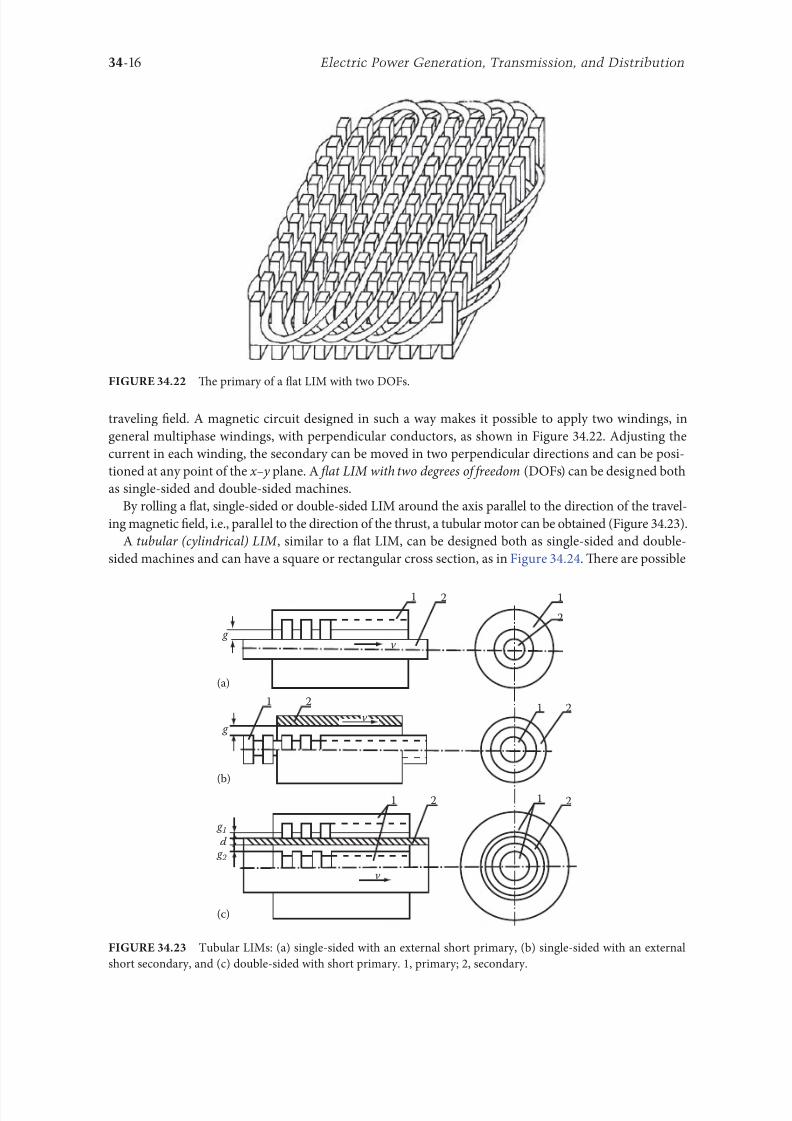
8102019 Power Handbook
httpslidepdfcomreaderfullpower-handbook 3143
34-16 Electric Power Generation Transmission and Distribution
traveling 1047297eld A magnetic circuit designed in such a way makes it possible to apply two windings in
general multiphase windings with perpendicular conductors as shown in Figure 3422 Adjusting the
current in each winding the secondary can be moved in two perpendicular directions and can be posi-
tioned at any point o the xndashy plane A 1047298at LIM with two degrees o reedom (DOFs) can be designed both
as single-sided and double-sided machines
By rolling a 1047298at single-sided or double-sided LIM around the axis parallel to the direction o the travel-
ing magnetic 1047297eld ie parallel to the direction o the thrust a tubular motor can be obtained (Figure 3423)
A tubular (cylindrical) LIM similar to a 1047298at LIM can be designed both as single-sided and double-
sided machines and can have a square or rectangular cross section as in Figure 3424 Tere are possible
Te primary o a 1047298at LIM with two DOFs
g
g
g 1
g 2
(c)
(b)
(a)
d
v
v
v
1
1
1 1
1
1
2
2
2
2
2
2
ubular LIMs (a) single-sided with an external short primary (b) single-sided with an external
short secondary and (c) double-sided with short primary 1 primary 2 secondary
8102019 Power Handbook
httpslidepdfcomreaderfullpower-handbook 3243
34-17Linear Electric Motors
con1047297gurations other than that in Figure 3423 regarding the length o the secondary with respect to thelength o the primary
All the aorementioned LIMs are motors with longitudinal magnetic 1047298ux ie the lines o magnetic
1047298ux lie in the plane parallel to the direction o the traveling magnetic 1047297eld A LIM can also be designed
in such a way as to obtain magnetic 1047298ux lines perpendicular to the direction o the traveling 1047297eld Such
motors are said to have transverse magnetic 1047298ux (Figure 3425)
Te undamental advantage o a LIM with transverse magnetic 1047298ux in comparison with a LIM with
longitudinal magnetic 1047298ux is the lower magnetizing current necessary due to the shorter magnetic 1047298ux
paths Te signi1047297cant disadvantage is lower thrust A 1047298at LIM with transverse magnetic 1047298ux usually has
a primary winding o concentrated coils located on salient poles
A 1047298at single-sided LIM with transverse 1047298ux can produce not only thrust but also electrodynamic
suspension In the design shown in Figure 3426 the secondary is suspended electrodynamically andpropelled and stabilized laterally by the primary magnetic 1047297eld [8] Te primary magnetic circuit con-
sists o E-shaped laminations assembled in two rows Te short secondary is made o light Al alloy in the
orm o a boat Te lateral sides o the boat are inclined by 60deg with respect to the active surace Such a
shape provides maximum normal repulsive orce and maximum lateral stabilization
According to their geometry the LIMs can be divided into the ollowing groups
bull With movable primary or movable secondary
bull Single sided and double sided
bull Flat and tubular
bull With short primary and short secondary
bull With longitudinal and transverse magnetic 1047298ux
1 2 3 4 1 2 3 4
ubular double-sided LIM with a square cross section 1 primary 2 secondary 3 primary coil
4 internal core
v
v
1 1
1
1
(a)
(b)
22
22
Flat LIM with transverse magnetic 1047298ux and salient poles (a) single-sided and (b) double-sided
1 primary 2 secondary
8102019 Power Handbook
httpslidepdfcomreaderfullpower-handbook 3343
34-18 Electric Power Generation Transmission and Distribution
Te linear speed o a LIM is
v s v s= minus( )1 (346)
where
s is the slip
v s is the synchronous speed according to Equation 341
Neglecting the longitudinal end effect [6] the electromagnetic thrust developed by a LIM can be
expressed in a similar way as or a rotary induction motor ie
F
m
v I
R
sdx
s
= prime( ) prime1
2
2 2
(347)
where
m1 is the number o phases o the primary winding
v s is the synchronous speed according to Equation 341
primeI 2 is the secondary current reerred to the primary system
primeR2 is the secondary resistance reerred to the primary system
s is the slip
Te secondary resistance primeR2 must include the so-called edge effect [6]
3422 Propulsion of Wheel-on-Rail Vehicles
Modern railway systems and electrical traction should meet the ollowing requirements
bull High level o automatization and computerization
bull Propulsion and braking independent o adhesion which in turn is affected 1047297rst o all by climate
and weather
bull Low level o noise sometimes below 70 dB (A)
Flat LIM with transverse magnetic 1047298ux salient poles and nonerromagnetic secondary pro-
pelled suspended and stabilized electrodynamically (From Gieras JF et al Analytical calculation o electro-
dynamic levitation orces in a special-purpose linear induction motor International Electric Machines and Drives
Conerence (IEMDCrsquo11) Niagara Falls Ontario Canada 2011 [on CD-ROM])
8102019 Power Handbook
httpslidepdfcomreaderfullpower-handbook 3443
34-19Linear Electric Motors
bull Ability to cope with high slopes at least 6 and sharp bends with radius o curvature less than 20 m
bull No pollution to natural environment and landscape
bull High reliability
Te congestion problems o big cities should be solved by creating collective transport orms that can be
implemented without affecting a highly populated city For example there are many cities in Italy where
the historical center has remained the same since the Renaissance A heavy railway might be a com-
pletely wrong solution and have a notable impact on the city planning An adequate solution might be
a light railway a people mover with transport capacity o 10000ndash20000 passengers per hour to replace
the traditional transport nets and to integrate the existing railway nets
All the requirements mentioned earlier can be met by using LIMs as propulsion machines Replacing
electrical rotary motors with linear motors in traction drives (electrical locomotives) generally does
not require new tracks but only their adjustment to linear drives Single-sided LIMs (Figure 3427a and b)
are best since the normal attractive orce o these can strengthen the adhesion o wheels and rails
Te air gap is rom 10 to 15 mm Most requently the motor car has two LIMs with short primaries
(Figure 3427a) assembled in series Te double-layer secondary consists o a solid back iron and an Al
cap and is located between the rails Cables or computer communication with the vehicle and quite
ofen collectors or electrical energy delivery to the vehicle are located along the track Tree-phaseLIMs are ed rom variable-voltage variable-requency (VVVF) voltage-source inverters A linear pro-
pulsion system o wheel-on-rail vehicles allows more 1047298exibility (Figure 3428) reducing noise on bends
and wear o the wheels and rails
Double-sided LIMs (Figure 3427c and d) have ound very limited application due to the technical
difficulty o eliminating aults caused by bends in the secondary with primary cores on either side It is
more difficult to keep a small and uniorm air gap in double-sided LIMs than that in single-sided LIMs
Te LIM-driven wheel-on-rail vehicles are built or low velocities ie less than 100 kmh and or
short routes ie less than 50 km (urban transit systems and short-distance trains) At present LIM-
driven trains operate in oronto and Vancouver BC Canada in Detroit MI (Figure 3429) okyo
(Figure 3430) and Osaka Japan and Kuala Lumpur Malaysia
(a) (b)
(c) (d)
LIM-driven wheel-on-rail cars (a) single-sided LIM with short primary mounted on the undercar-
riage (b) single-sided LIM with short secondary mounted on the undercarriage (c) double-sided LIM with short pri-
mary mounted on the undercarriage and (d) double-sided LIM with short secondary mounted on the undercarriage
8102019 Power Handbook
httpslidepdfcomreaderfullpower-handbook 3543
34-20 Electric Power Generation Transmission and Distribution
(a) (b)
Te undercarriage o a wheel-on-rail vehicle (a) rotary motor propulsion and (b) LIM propulsion
Detroit people mover driven by single-sided LIMs
oei Oedo subway line in okyo driven by single-sided LIMs
8102019 Power Handbook
httpslidepdfcomreaderfullpower-handbook 3643
34-21Linear Electric Motors
Te design data o some single-sided traction LIMs are presented in able 347 and double-sided trac-
tion LIMs in able 348
343 Variable Reluctance Motors
Te simplest construction o a variable reluctance LSM or linear reluctance motor (LRM) is that shown
in Figure 3418 with DC excitation winding being removed However the thrust o such a motor wouldbe low as the ratio o d -axis permeance to q-axis permeance is low Better perormance can be obtained
when using 1047298ux barriers [18] or steel laminations [15] o make 1047298ux barriers any nonerromagnetic
materials can be used o obtain high permeance (low reluctance) in the d -axis and low permeance in
the q-axis steel laminations should be oriented in such a way as to create high permeance or the d -axis
magnetic 1047298ux
Figure 3431a shows a variable reluctance platen with 1047298ux barriers and Figure 3431b shows how to
arrange steel laminations to obtain different reluctances in the d - and q-axes Te platen can be com-
posed o segments the length o which is equal to the pole pitchτ Each segment consists o semicircular
lamellas cut out rom electrotechnical sheet A 1047297lling or example epoxy resin is used to make the seg-
ment rigid and robust By putting the segments together a platen o any desired length can be obtained
Design Data o Single-Sided Tree-Phase LIMs or Propulsion o Vehicles
Quantity
LIM
UnitJLMDR ICS KU CIGG GEC
Pullout thrust at requency given
in the ollowing F x
125 90 35 17 07 kN
Input requency 200 400 250 400 600 Hz
Rated phase current V 1 2750 4650 1300 2000 2000 A
Number o poles 2 p 8 6 4 6 4 mdash
Number o turns per phase N 1 128 96 128 108 48 mdash
Equivalent diameter o conductor d 1 mdash 893 528 1115 81 mm
Number o parallel conductors mdash 1 mdash 19 1 mdash
Effective width o primary core Li 023 0216 029 0101 01715 m
Pole pitch τ 027 02868 030 025 020 m
Length o single end connection l e mdash 03483 mdash 02955 03685 m
Coil pitch wc 0225 01673 025 01944 01555 m
Air gap g 150 126 120 150 182 mm
Number o slots z 1( primez 1) 96(106) 72(79) 48(58) 54(61) 36(43) mdash
Width o slot b11 mdash 156 170 150 1308 mm
Width o slot opening b14 mdash 156 mdash 1044 1308 mm
Depth o slot h11 mdash 530 380 3421 6147 mm
Height o yoke h1 y mdash 436 393 7163 500 mm
Conductivity o back iron at 20degC σFe mdash 446 952 446 512 times106 Sm
Conductivity o Al cap at 20degC σ Al mdash 300 303 323 215 times106 Sm
Width o back iron w 03 024 03 0111 01715 m
Tickness o back iron hsec 190 125 250 254 474 mm
Tickness o Al cap d 50 45 50 45(25) 32 mm
Tickness o Al cap behind Fe core t ov 50 170 50 127 32 mm
Width o Al cap 030 032 040 0201 02985 m
JLMDR Japanese Linear Motor Driven Railcar Japan ICS Intermediate Capacity ransit System Canada KU
Kyushu University LIM Japan CIGG Canadian Inst o Guided Ground ransport Canada GEC General
Electric Company United States (z 1 ) is the number o hal 1047297lled slots
8102019 Power Handbook
httpslidepdfcomreaderfullpower-handbook 3743
34-22 Electric Power Generation Transmission and Distribution
344 Stepping Motors
A linear stepping motor has a concentrated armature winding wound on salient poles and PM excitation
rail or variable reluctance platen Te thrust is generated as an action o the armature magnetic 1047298ux and
PM 1047298ux (active platen) or the armature magnetic 1047298ux and salient erromagnetic poles (variable reluc-
tance platen) Stepping motors have no position eedback
Design Data o Double-Sided Tree-Phase LIMs or Propulsion
o Vehicles
Quantity
LIM
UnitGEC LIMVR
Maximum thrust at input requency F x given in the ollowing 085 1668 kN
Input requency 600 1730 Hz
Input phase current I 1 2000 20000 A
Number o poles 2 p 4 10 mdash
Number o turns per phase N 1 144 100 mdash
Diameter o conductor d 1 075 110 mm
Effective width o primary core Li 00869 0254 m
Pole pitch τ 01795 03556 m
Coil pitch wc 005 005 m
Number o slots z 1( primez 1) 36(45) 150(160) mdash
Width o slot b11 137 160 mm
Width o slot opening b14 137 mdash mm
Depth o slot h1 630 mdash mm
Height o yoke h1 y 239 mdash mm
Width o tooth c1 200 77 mm
Resultant air gap 2 g + d 381 38075 mm
Air gap g 2 times 127 2 times 111 mm
Tickness o secondary d 127 15875(hollow) mm
Effective thickness o Al secondary 127 72 mm
Width o secondary w ge03046 mdash m
Conductivity o Al cap at 20degC σ Al asymp2434 asymp240 times106 Sm
GEC General Electric Company United States LIMVR LIM Research Vehicle
Pueblo CO United States (z 1 ) is the number o hal 1047297lled slots
(a) (b)
q q d d d q d q d d
Laminations
τ τ τ τ
Epoxy resin
Variable reluctance LSMs with (a) 1047298ux barriers and (b) steel laminations
8102019 Power Handbook
httpslidepdfcomreaderfullpower-handbook 3843
8102019 Power Handbook
httpslidepdfcomreaderfullpower-handbook 3943
34-24 Electric Power Generation Transmission and Distribution
Tis value is different or ull-step and microstepping drives Te maximum startndashstop speed is the
maximum speed that can be used when starting or stopping the motor without ramping that does not
cause the motor to all out o synchronism or lose steps Te maximum speed is the maximum linear
speed that can be achieved without the motor stalling or alling out o synchronism Te maximum
load mass is the maximum allowable mass applied to the orcer against the scale that does not result in
mechanical damage Te ull-step resolution is the position increment obtained when the currents are
switched rom one winding to the next winding Tis is the typical resolution obtained with ul l-step
drives and it is strictly a unction o the motor construction Te microstepping resolution is the position
increment obtained when the ull-step resolution is divided electronically by proportioning the currents
in the two windings Tis resolution is typically 10ndash250 times smaller than the ull-step resolution [13]
HLSMs are regarded as an excellent solution to positioning systems that require a high accuracy
and rapid acceleration With a microprocessor controlled microstepping mode a smooth operation with
standard resolution o a ew hundred stepsmm can be obtained Te advantages such as high efficiencyhigh throughput mechanical simplicity high reliability precise open-loop operation and low inertia
o the system have made these kind o motors more and more attractive in such applications as actory
automation high speed positioning computer peripherals acsimile machines numerically controlled
machine tools automated medical equipment automated laboratory equipment and welding robots
Tis motor is especially suitable or machine tools printers plotters and computer-controlled material
handling in which a high positioning accuracy and repeatability are the key problems
When two or our orcers mounted at 90deg and a special grooved platen (ldquowaffle platerdquo) are used the
xndashy motion (two DOFs) in a single plane is obtained (Figure 3434)
Speci1047297cation data o the xndashy HLSMs manuactured by Normag Northern Magnetics Inc Santa
Clarita CA are given in able 3410
PM linear stepping motors (Photo courtesy o okyo Aircraf Instrument Co Ltd okyo Japan)
8102019 Power Handbook
httpslidepdfcomreaderfullpower-handbook 4043
34-25Linear Electric Motors
345 Switched Reluctance Motors
Te topology o a linear switched reluctance motor is similar to that o a stepping motor with variable
reluctance platen In addition it is equipped with position sensors Te turn-on and turn-off instant o
the input current is synchronized with the position o the moving part Te thrust is very sensitive to
the turn-on and turn-off instant
In the case o a linear stepping or linear switched reluctance motor the speed v o the moving part is
v v s sw= = τ
(348)
where
sw is the undamental switching requency in one armature phase winding
τ is the pole pitch o the reaction rail
For a rotary stepping or switched reluctance motor sw = 2 pr n where 2 pr is the number o rotor poles and
n is rotational speed in revs
A linear switched reluctance motor has a doubly salient magnetic circuit with a polyphase winding
on the armature Longitudinal and transverse 1047298ux designs are shown in Figure 3435 A linear switched
reluctance motor allows precise speed and position-controlled linear motion at low speeds and is not sub-
ject to design constraints (minimum speed limited by minimum easible pole pitch) o linear AC motors
x
y
12
3
4
1
1
2
2
HLSM with a our-unit orcer to obtain the xndashy motion 1 orcers or the x -direction 2 orcers
or the y -direction 3 platen 4 air pressure
Data o xndashy HLSMs Manuactured by Normag Northern Magnetics Inc
Santa Clarita CA
Parameter 4XY0602-2-0 4XY2002-2-0 4XY2004-2-0 4XY2504-2-0
Number o orcer units per axis 1 1 2 2
Number o phases 2 2 2(4) 2(4)Static thrust N 133 400 980 1330
Trust at 1 ms N 111 311 712 980
Normal attractive orce N 1600 4000 14400 18000
Resistance per phase Ω 29 33 16 19
Inductance per phase mH 15 40 20 23
Input phase current A 20 20 40 40
Air gap mm 002
Maximum temperature degC 110
Mass kg 32 072 20 15
Repeatability mm 000254
Resolution mm 000254
Bearing type Air
8102019 Power Handbook
httpslidepdfcomreaderfullpower-handbook 4143
34-26 Electric Power Generation Transmission and Distribution
346 Linear Positioning Stages
Linear motors are now playing a key role in advanced precision linear positioning Linear precision posi-
tioning systems can be classi1047297ed into open-loop systems with HLSMs and closed-loop servo systems
with LSMs LBMs or LIMs
A PM LSMndashdriven positioning stage is shown in Figure 3436 A stationary base is made o Al steel
ceramic or granite plate It provides a stable precise and 1047298at platorm to which all stationary position-
ing components are attached Te base o the stage is attached to the host system with the aid o mount-
ing screws
Te moving table accommodates all moving positioning components o achieve maximum accelera-
tion the mass o the moving table should be as small as possible and usually Al is used as a lightweight
material A number o mounting holes on the moving table is necessary to 1047297x the payload to the mount-
ing table
Linear bearing rails provide a precise guidance to the moving table A minimum o one bearing rail
is required Linear ball bearing or air bearings are attached to each rail
Te armature o a linear motor is astened to the moving table and reaction rail (PM excitation sys-tem) is built in the base between the rails (Figure 3436)
A linear encoder is needed to obtain precise control o position o the table velocity and acceleration
Te read head o the encoder is attached to the moving table
(a) (b)
3
3
221
1
Linear switched reluctance motor con1047297gurations (a) longitudinal 1047298ux design and (b) transverse
1047298ux design 1 armature winding 2 armature stack 3 platen
12
3
5
4
7
6
8
Linear positioning stage driven by PM LBM 1 base 2 moving table 3 armature o LBM 4 PMs
5 linear bearing 6 encoder 7 cable carrier 8 limit switch (Courtesy o Normag Santa Clarita CA)
8102019 Power Handbook
httpslidepdfcomreaderfullpower-handbook 4243
34-27Linear Electric Motors
Noncontact limit switches ixed to the base provide an overtravel protection and init ial homing
A cable carrier accommodates and routes electrical cables between the moving table and stationary
connector box 1047297xed to the base
An HLSM-driven linear precision stage is o similar construction Instead o PMs between bearing
rails it has a variable reluctance platen HLSMs usually need air bearings and in addition to the electri-
cal cables an air hose between air bearings and the compressor is requiredLinear positioning stages are used in semiconductor technology electronic assembly quality assur-
ance laser cutting optical scanning water jet cutting gantry systems (x y z stages) color printers
plotters and Cartesian coordinate robotics
References
1 Anorad Linear Motors Inormation Brochure Anorad Hauppauge New York 2007 wwwanoradcom
2 Boldea I and Nasar SA Linear Motion Electromagnetic Systems John Wiley amp Sons New York 1985
3 Boldea I and Nasar SA Linear Electric Actuators and Generators Cambridge University Press
New York 2005
4 Compumotor Digiplan Positioning Control Systems and Drives Parker Hanni1047297n CorporationRohnert Park CA 2011
5 Everes W Henneberger G Wunderlich H and Selig A A linear homopolar motor or a trans-
portation system 2nd International Symposium on Linear Drives or Industry Applications (LDIArsquo98)
okyo Japan 1998 pp 46ndash49
6 Gieras JF Linear Induction Drives Clarendon Press Oxord UK 1994
7 Gieras JF Status o linear motors in the United States International Symposium on Linear Drives
or Industry Applications (LDIArsquo03) Birmingham UK 2003 pp 169ndash176
8 Gieras JF Gientkowski Z Mews J and Splawski P Analytical calculation o electrodynamic
levitation orces in a special-purpose linear induction motor International Electric Machines and
Drives Conerence (IEMDCrsquo11) Niagara Falls Ontario Canada 2011 [on CD-ROM]
9 Gieras JF Piech ZJ and omczuk BZ Linear Synchronous Motors ransportation and Automation Systems aylor amp Francis (CRC Press) Boca Raton FL 2011
10 Hoang E Ahmed AHB and Lucidarme J Switching 1047298ux permanent magnet polyphase syn-
chronous machines 7th European Conerence on Power Electronics and Applications (EPErsquo97)
Vol 3 rondheim Norway 1977 pp 903ndash908
11 Kollmorgen Linear Motors Aim to Cut Cost o Semiconductors and Electronics Manuacture
Kollmorgen Radord VA 1997
12 Laithwaite ER A History o Linear Electric Motors Macmillan London UK 1987
13 Linear Step Motor Inormation Brochure okyo Aircraf Instrument Co Ltd okyo Japan
1998
14 LinMot Design Manual Sulzer Electronics Ltd Zuumlrich Switzerland 1999
15 Locci N and Marongiu I Modelling and testing a new linear reluctance motor InternationalConerence on Electrical Machines (ICEMrsquo92) Vol 2 Manchester UK 1992 pp 706ndash710
16 Rauch SE and Johnson LJ Design principles o 1047298ux-switch alternators AIEE rans Part III
74(12) 1261ndash1269 1955
17 Rosenmayr M Casat Glavitsch A and Stemmler H SwissmetromdashPower supply or a high-
power-propulsion system with short stator linear motors 15th International Conerence on
Magnetically Levitated Systems and Linear Drives Maglevrsquo98 Mount Fuji Yamanashi Japan 1998
pp 280ndash286
18 Sanada M Morimoto S and akeda Y Reluctance equalization design o multi 1047298ux barrier con-
struction or linear synchronous reluctance motors 2nd International Symposium on Linear Drives
or Industrial Applications (LDIArsquo98) okyo Japan 1998 pp 259ndash262
8102019 Power Handbook
httpslidepdfcomreaderfullpower-handbook 4343
34-28 Electric Power Generation Transmission and Distribution
19 Seok-Myeong J and Sang-Sub J Design and analysis o the linear homopolar synchronous motor
or integrated magnetic propulsion and suspension 2nd International Symposium on Linear Drives
or Industrial Applications (LDIArsquo98) okyo Japan 1998 pp 74ndash77
20 Synchronous Linear Motor 1FN6 Te Electrical Gear Rack Siemens AG Industry Sector Drive
echnologies Motion Control Erlangen Germany 2008
21 Yamada H Handbook o Linear Motor Applications (in Japanese) Kogyo Chosaki Publishing Cookyo Japan 1986
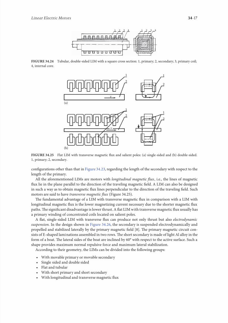
8102019 Power Handbook
httpslidepdfcomreaderfullpower-handbook 3243
34-17Linear Electric Motors
con1047297gurations other than that in Figure 3423 regarding the length o the secondary with respect to thelength o the primary
All the aorementioned LIMs are motors with longitudinal magnetic 1047298ux ie the lines o magnetic
1047298ux lie in the plane parallel to the direction o the traveling magnetic 1047297eld A LIM can also be designed
in such a way as to obtain magnetic 1047298ux lines perpendicular to the direction o the traveling 1047297eld Such
motors are said to have transverse magnetic 1047298ux (Figure 3425)
Te undamental advantage o a LIM with transverse magnetic 1047298ux in comparison with a LIM with
longitudinal magnetic 1047298ux is the lower magnetizing current necessary due to the shorter magnetic 1047298ux
paths Te signi1047297cant disadvantage is lower thrust A 1047298at LIM with transverse magnetic 1047298ux usually has
a primary winding o concentrated coils located on salient poles
A 1047298at single-sided LIM with transverse 1047298ux can produce not only thrust but also electrodynamic
suspension In the design shown in Figure 3426 the secondary is suspended electrodynamically andpropelled and stabilized laterally by the primary magnetic 1047297eld [8] Te primary magnetic circuit con-
sists o E-shaped laminations assembled in two rows Te short secondary is made o light Al alloy in the
orm o a boat Te lateral sides o the boat are inclined by 60deg with respect to the active surace Such a
shape provides maximum normal repulsive orce and maximum lateral stabilization
According to their geometry the LIMs can be divided into the ollowing groups
bull With movable primary or movable secondary
bull Single sided and double sided
bull Flat and tubular
bull With short primary and short secondary
bull With longitudinal and transverse magnetic 1047298ux
1 2 3 4 1 2 3 4
ubular double-sided LIM with a square cross section 1 primary 2 secondary 3 primary coil
4 internal core
v
v
1 1
1
1
(a)
(b)
22
22
Flat LIM with transverse magnetic 1047298ux and salient poles (a) single-sided and (b) double-sided
1 primary 2 secondary
8102019 Power Handbook
httpslidepdfcomreaderfullpower-handbook 3343
34-18 Electric Power Generation Transmission and Distribution
Te linear speed o a LIM is
v s v s= minus( )1 (346)
where
s is the slip
v s is the synchronous speed according to Equation 341
Neglecting the longitudinal end effect [6] the electromagnetic thrust developed by a LIM can be
expressed in a similar way as or a rotary induction motor ie
F
m
v I
R
sdx
s
= prime( ) prime1
2
2 2
(347)
where
m1 is the number o phases o the primary winding
v s is the synchronous speed according to Equation 341
primeI 2 is the secondary current reerred to the primary system
primeR2 is the secondary resistance reerred to the primary system
s is the slip
Te secondary resistance primeR2 must include the so-called edge effect [6]
3422 Propulsion of Wheel-on-Rail Vehicles
Modern railway systems and electrical traction should meet the ollowing requirements
bull High level o automatization and computerization
bull Propulsion and braking independent o adhesion which in turn is affected 1047297rst o all by climate
and weather
bull Low level o noise sometimes below 70 dB (A)
Flat LIM with transverse magnetic 1047298ux salient poles and nonerromagnetic secondary pro-
pelled suspended and stabilized electrodynamically (From Gieras JF et al Analytical calculation o electro-
dynamic levitation orces in a special-purpose linear induction motor International Electric Machines and Drives
Conerence (IEMDCrsquo11) Niagara Falls Ontario Canada 2011 [on CD-ROM])
8102019 Power Handbook
httpslidepdfcomreaderfullpower-handbook 3443
34-19Linear Electric Motors
bull Ability to cope with high slopes at least 6 and sharp bends with radius o curvature less than 20 m
bull No pollution to natural environment and landscape
bull High reliability
Te congestion problems o big cities should be solved by creating collective transport orms that can be
implemented without affecting a highly populated city For example there are many cities in Italy where
the historical center has remained the same since the Renaissance A heavy railway might be a com-
pletely wrong solution and have a notable impact on the city planning An adequate solution might be
a light railway a people mover with transport capacity o 10000ndash20000 passengers per hour to replace
the traditional transport nets and to integrate the existing railway nets
All the requirements mentioned earlier can be met by using LIMs as propulsion machines Replacing
electrical rotary motors with linear motors in traction drives (electrical locomotives) generally does
not require new tracks but only their adjustment to linear drives Single-sided LIMs (Figure 3427a and b)
are best since the normal attractive orce o these can strengthen the adhesion o wheels and rails
Te air gap is rom 10 to 15 mm Most requently the motor car has two LIMs with short primaries
(Figure 3427a) assembled in series Te double-layer secondary consists o a solid back iron and an Al
cap and is located between the rails Cables or computer communication with the vehicle and quite
ofen collectors or electrical energy delivery to the vehicle are located along the track Tree-phaseLIMs are ed rom variable-voltage variable-requency (VVVF) voltage-source inverters A linear pro-
pulsion system o wheel-on-rail vehicles allows more 1047298exibility (Figure 3428) reducing noise on bends
and wear o the wheels and rails
Double-sided LIMs (Figure 3427c and d) have ound very limited application due to the technical
difficulty o eliminating aults caused by bends in the secondary with primary cores on either side It is
more difficult to keep a small and uniorm air gap in double-sided LIMs than that in single-sided LIMs
Te LIM-driven wheel-on-rail vehicles are built or low velocities ie less than 100 kmh and or
short routes ie less than 50 km (urban transit systems and short-distance trains) At present LIM-
driven trains operate in oronto and Vancouver BC Canada in Detroit MI (Figure 3429) okyo
(Figure 3430) and Osaka Japan and Kuala Lumpur Malaysia
(a) (b)
(c) (d)
LIM-driven wheel-on-rail cars (a) single-sided LIM with short primary mounted on the undercar-
riage (b) single-sided LIM with short secondary mounted on the undercarriage (c) double-sided LIM with short pri-
mary mounted on the undercarriage and (d) double-sided LIM with short secondary mounted on the undercarriage
8102019 Power Handbook
httpslidepdfcomreaderfullpower-handbook 3543
34-20 Electric Power Generation Transmission and Distribution
(a) (b)
Te undercarriage o a wheel-on-rail vehicle (a) rotary motor propulsion and (b) LIM propulsion
Detroit people mover driven by single-sided LIMs
oei Oedo subway line in okyo driven by single-sided LIMs
8102019 Power Handbook
httpslidepdfcomreaderfullpower-handbook 3643
34-21Linear Electric Motors
Te design data o some single-sided traction LIMs are presented in able 347 and double-sided trac-
tion LIMs in able 348
343 Variable Reluctance Motors
Te simplest construction o a variable reluctance LSM or linear reluctance motor (LRM) is that shown
in Figure 3418 with DC excitation winding being removed However the thrust o such a motor wouldbe low as the ratio o d -axis permeance to q-axis permeance is low Better perormance can be obtained
when using 1047298ux barriers [18] or steel laminations [15] o make 1047298ux barriers any nonerromagnetic
materials can be used o obtain high permeance (low reluctance) in the d -axis and low permeance in
the q-axis steel laminations should be oriented in such a way as to create high permeance or the d -axis
magnetic 1047298ux
Figure 3431a shows a variable reluctance platen with 1047298ux barriers and Figure 3431b shows how to
arrange steel laminations to obtain different reluctances in the d - and q-axes Te platen can be com-
posed o segments the length o which is equal to the pole pitchτ Each segment consists o semicircular
lamellas cut out rom electrotechnical sheet A 1047297lling or example epoxy resin is used to make the seg-
ment rigid and robust By putting the segments together a platen o any desired length can be obtained
Design Data o Single-Sided Tree-Phase LIMs or Propulsion o Vehicles
Quantity
LIM
UnitJLMDR ICS KU CIGG GEC
Pullout thrust at requency given
in the ollowing F x
125 90 35 17 07 kN
Input requency 200 400 250 400 600 Hz
Rated phase current V 1 2750 4650 1300 2000 2000 A
Number o poles 2 p 8 6 4 6 4 mdash
Number o turns per phase N 1 128 96 128 108 48 mdash
Equivalent diameter o conductor d 1 mdash 893 528 1115 81 mm
Number o parallel conductors mdash 1 mdash 19 1 mdash
Effective width o primary core Li 023 0216 029 0101 01715 m
Pole pitch τ 027 02868 030 025 020 m
Length o single end connection l e mdash 03483 mdash 02955 03685 m
Coil pitch wc 0225 01673 025 01944 01555 m
Air gap g 150 126 120 150 182 mm
Number o slots z 1( primez 1) 96(106) 72(79) 48(58) 54(61) 36(43) mdash
Width o slot b11 mdash 156 170 150 1308 mm
Width o slot opening b14 mdash 156 mdash 1044 1308 mm
Depth o slot h11 mdash 530 380 3421 6147 mm
Height o yoke h1 y mdash 436 393 7163 500 mm
Conductivity o back iron at 20degC σFe mdash 446 952 446 512 times106 Sm
Conductivity o Al cap at 20degC σ Al mdash 300 303 323 215 times106 Sm
Width o back iron w 03 024 03 0111 01715 m
Tickness o back iron hsec 190 125 250 254 474 mm
Tickness o Al cap d 50 45 50 45(25) 32 mm
Tickness o Al cap behind Fe core t ov 50 170 50 127 32 mm
Width o Al cap 030 032 040 0201 02985 m
JLMDR Japanese Linear Motor Driven Railcar Japan ICS Intermediate Capacity ransit System Canada KU
Kyushu University LIM Japan CIGG Canadian Inst o Guided Ground ransport Canada GEC General
Electric Company United States (z 1 ) is the number o hal 1047297lled slots
8102019 Power Handbook
httpslidepdfcomreaderfullpower-handbook 3743
34-22 Electric Power Generation Transmission and Distribution
344 Stepping Motors
A linear stepping motor has a concentrated armature winding wound on salient poles and PM excitation
rail or variable reluctance platen Te thrust is generated as an action o the armature magnetic 1047298ux and
PM 1047298ux (active platen) or the armature magnetic 1047298ux and salient erromagnetic poles (variable reluc-
tance platen) Stepping motors have no position eedback
Design Data o Double-Sided Tree-Phase LIMs or Propulsion
o Vehicles
Quantity
LIM
UnitGEC LIMVR
Maximum thrust at input requency F x given in the ollowing 085 1668 kN
Input requency 600 1730 Hz
Input phase current I 1 2000 20000 A
Number o poles 2 p 4 10 mdash
Number o turns per phase N 1 144 100 mdash
Diameter o conductor d 1 075 110 mm
Effective width o primary core Li 00869 0254 m
Pole pitch τ 01795 03556 m
Coil pitch wc 005 005 m
Number o slots z 1( primez 1) 36(45) 150(160) mdash
Width o slot b11 137 160 mm
Width o slot opening b14 137 mdash mm
Depth o slot h1 630 mdash mm
Height o yoke h1 y 239 mdash mm
Width o tooth c1 200 77 mm
Resultant air gap 2 g + d 381 38075 mm
Air gap g 2 times 127 2 times 111 mm
Tickness o secondary d 127 15875(hollow) mm
Effective thickness o Al secondary 127 72 mm
Width o secondary w ge03046 mdash m
Conductivity o Al cap at 20degC σ Al asymp2434 asymp240 times106 Sm
GEC General Electric Company United States LIMVR LIM Research Vehicle
Pueblo CO United States (z 1 ) is the number o hal 1047297lled slots
(a) (b)
q q d d d q d q d d
Laminations
τ τ τ τ
Epoxy resin
Variable reluctance LSMs with (a) 1047298ux barriers and (b) steel laminations
8102019 Power Handbook
httpslidepdfcomreaderfullpower-handbook 3843
8102019 Power Handbook
httpslidepdfcomreaderfullpower-handbook 3943
34-24 Electric Power Generation Transmission and Distribution
Tis value is different or ull-step and microstepping drives Te maximum startndashstop speed is the
maximum speed that can be used when starting or stopping the motor without ramping that does not
cause the motor to all out o synchronism or lose steps Te maximum speed is the maximum linear
speed that can be achieved without the motor stalling or alling out o synchronism Te maximum
load mass is the maximum allowable mass applied to the orcer against the scale that does not result in
mechanical damage Te ull-step resolution is the position increment obtained when the currents are
switched rom one winding to the next winding Tis is the typical resolution obtained with ul l-step
drives and it is strictly a unction o the motor construction Te microstepping resolution is the position
increment obtained when the ull-step resolution is divided electronically by proportioning the currents
in the two windings Tis resolution is typically 10ndash250 times smaller than the ull-step resolution [13]
HLSMs are regarded as an excellent solution to positioning systems that require a high accuracy
and rapid acceleration With a microprocessor controlled microstepping mode a smooth operation with
standard resolution o a ew hundred stepsmm can be obtained Te advantages such as high efficiencyhigh throughput mechanical simplicity high reliability precise open-loop operation and low inertia
o the system have made these kind o motors more and more attractive in such applications as actory
automation high speed positioning computer peripherals acsimile machines numerically controlled
machine tools automated medical equipment automated laboratory equipment and welding robots
Tis motor is especially suitable or machine tools printers plotters and computer-controlled material
handling in which a high positioning accuracy and repeatability are the key problems
When two or our orcers mounted at 90deg and a special grooved platen (ldquowaffle platerdquo) are used the
xndashy motion (two DOFs) in a single plane is obtained (Figure 3434)
Speci1047297cation data o the xndashy HLSMs manuactured by Normag Northern Magnetics Inc Santa
Clarita CA are given in able 3410
PM linear stepping motors (Photo courtesy o okyo Aircraf Instrument Co Ltd okyo Japan)
8102019 Power Handbook
httpslidepdfcomreaderfullpower-handbook 4043
34-25Linear Electric Motors
345 Switched Reluctance Motors
Te topology o a linear switched reluctance motor is similar to that o a stepping motor with variable
reluctance platen In addition it is equipped with position sensors Te turn-on and turn-off instant o
the input current is synchronized with the position o the moving part Te thrust is very sensitive to
the turn-on and turn-off instant
In the case o a linear stepping or linear switched reluctance motor the speed v o the moving part is
v v s sw= = τ
(348)
where
sw is the undamental switching requency in one armature phase winding
τ is the pole pitch o the reaction rail
For a rotary stepping or switched reluctance motor sw = 2 pr n where 2 pr is the number o rotor poles and
n is rotational speed in revs
A linear switched reluctance motor has a doubly salient magnetic circuit with a polyphase winding
on the armature Longitudinal and transverse 1047298ux designs are shown in Figure 3435 A linear switched
reluctance motor allows precise speed and position-controlled linear motion at low speeds and is not sub-
ject to design constraints (minimum speed limited by minimum easible pole pitch) o linear AC motors
x
y
12
3
4
1
1
2
2
HLSM with a our-unit orcer to obtain the xndashy motion 1 orcers or the x -direction 2 orcers
or the y -direction 3 platen 4 air pressure
Data o xndashy HLSMs Manuactured by Normag Northern Magnetics Inc
Santa Clarita CA
Parameter 4XY0602-2-0 4XY2002-2-0 4XY2004-2-0 4XY2504-2-0
Number o orcer units per axis 1 1 2 2
Number o phases 2 2 2(4) 2(4)Static thrust N 133 400 980 1330
Trust at 1 ms N 111 311 712 980
Normal attractive orce N 1600 4000 14400 18000
Resistance per phase Ω 29 33 16 19
Inductance per phase mH 15 40 20 23
Input phase current A 20 20 40 40
Air gap mm 002
Maximum temperature degC 110
Mass kg 32 072 20 15
Repeatability mm 000254
Resolution mm 000254
Bearing type Air
8102019 Power Handbook
httpslidepdfcomreaderfullpower-handbook 4143
34-26 Electric Power Generation Transmission and Distribution
346 Linear Positioning Stages
Linear motors are now playing a key role in advanced precision linear positioning Linear precision posi-
tioning systems can be classi1047297ed into open-loop systems with HLSMs and closed-loop servo systems
with LSMs LBMs or LIMs
A PM LSMndashdriven positioning stage is shown in Figure 3436 A stationary base is made o Al steel
ceramic or granite plate It provides a stable precise and 1047298at platorm to which all stationary position-
ing components are attached Te base o the stage is attached to the host system with the aid o mount-
ing screws
Te moving table accommodates all moving positioning components o achieve maximum accelera-
tion the mass o the moving table should be as small as possible and usually Al is used as a lightweight
material A number o mounting holes on the moving table is necessary to 1047297x the payload to the mount-
ing table
Linear bearing rails provide a precise guidance to the moving table A minimum o one bearing rail
is required Linear ball bearing or air bearings are attached to each rail
Te armature o a linear motor is astened to the moving table and reaction rail (PM excitation sys-tem) is built in the base between the rails (Figure 3436)
A linear encoder is needed to obtain precise control o position o the table velocity and acceleration
Te read head o the encoder is attached to the moving table
(a) (b)
3
3
221
1
Linear switched reluctance motor con1047297gurations (a) longitudinal 1047298ux design and (b) transverse
1047298ux design 1 armature winding 2 armature stack 3 platen
12
3
5
4
7
6
8
Linear positioning stage driven by PM LBM 1 base 2 moving table 3 armature o LBM 4 PMs
5 linear bearing 6 encoder 7 cable carrier 8 limit switch (Courtesy o Normag Santa Clarita CA)
8102019 Power Handbook
httpslidepdfcomreaderfullpower-handbook 4243
34-27Linear Electric Motors
Noncontact limit switches ixed to the base provide an overtravel protection and init ial homing
A cable carrier accommodates and routes electrical cables between the moving table and stationary
connector box 1047297xed to the base
An HLSM-driven linear precision stage is o similar construction Instead o PMs between bearing
rails it has a variable reluctance platen HLSMs usually need air bearings and in addition to the electri-
cal cables an air hose between air bearings and the compressor is requiredLinear positioning stages are used in semiconductor technology electronic assembly quality assur-
ance laser cutting optical scanning water jet cutting gantry systems (x y z stages) color printers
plotters and Cartesian coordinate robotics
References
1 Anorad Linear Motors Inormation Brochure Anorad Hauppauge New York 2007 wwwanoradcom
2 Boldea I and Nasar SA Linear Motion Electromagnetic Systems John Wiley amp Sons New York 1985
3 Boldea I and Nasar SA Linear Electric Actuators and Generators Cambridge University Press
New York 2005
4 Compumotor Digiplan Positioning Control Systems and Drives Parker Hanni1047297n CorporationRohnert Park CA 2011
5 Everes W Henneberger G Wunderlich H and Selig A A linear homopolar motor or a trans-
portation system 2nd International Symposium on Linear Drives or Industry Applications (LDIArsquo98)
okyo Japan 1998 pp 46ndash49
6 Gieras JF Linear Induction Drives Clarendon Press Oxord UK 1994
7 Gieras JF Status o linear motors in the United States International Symposium on Linear Drives
or Industry Applications (LDIArsquo03) Birmingham UK 2003 pp 169ndash176
8 Gieras JF Gientkowski Z Mews J and Splawski P Analytical calculation o electrodynamic
levitation orces in a special-purpose linear induction motor International Electric Machines and
Drives Conerence (IEMDCrsquo11) Niagara Falls Ontario Canada 2011 [on CD-ROM]
9 Gieras JF Piech ZJ and omczuk BZ Linear Synchronous Motors ransportation and Automation Systems aylor amp Francis (CRC Press) Boca Raton FL 2011
10 Hoang E Ahmed AHB and Lucidarme J Switching 1047298ux permanent magnet polyphase syn-
chronous machines 7th European Conerence on Power Electronics and Applications (EPErsquo97)
Vol 3 rondheim Norway 1977 pp 903ndash908
11 Kollmorgen Linear Motors Aim to Cut Cost o Semiconductors and Electronics Manuacture
Kollmorgen Radord VA 1997
12 Laithwaite ER A History o Linear Electric Motors Macmillan London UK 1987
13 Linear Step Motor Inormation Brochure okyo Aircraf Instrument Co Ltd okyo Japan
1998
14 LinMot Design Manual Sulzer Electronics Ltd Zuumlrich Switzerland 1999
15 Locci N and Marongiu I Modelling and testing a new linear reluctance motor InternationalConerence on Electrical Machines (ICEMrsquo92) Vol 2 Manchester UK 1992 pp 706ndash710
16 Rauch SE and Johnson LJ Design principles o 1047298ux-switch alternators AIEE rans Part III
74(12) 1261ndash1269 1955
17 Rosenmayr M Casat Glavitsch A and Stemmler H SwissmetromdashPower supply or a high-
power-propulsion system with short stator linear motors 15th International Conerence on
Magnetically Levitated Systems and Linear Drives Maglevrsquo98 Mount Fuji Yamanashi Japan 1998
pp 280ndash286
18 Sanada M Morimoto S and akeda Y Reluctance equalization design o multi 1047298ux barrier con-
struction or linear synchronous reluctance motors 2nd International Symposium on Linear Drives
or Industrial Applications (LDIArsquo98) okyo Japan 1998 pp 259ndash262
8102019 Power Handbook
httpslidepdfcomreaderfullpower-handbook 4343
34-28 Electric Power Generation Transmission and Distribution
19 Seok-Myeong J and Sang-Sub J Design and analysis o the linear homopolar synchronous motor
or integrated magnetic propulsion and suspension 2nd International Symposium on Linear Drives
or Industrial Applications (LDIArsquo98) okyo Japan 1998 pp 74ndash77
20 Synchronous Linear Motor 1FN6 Te Electrical Gear Rack Siemens AG Industry Sector Drive
echnologies Motion Control Erlangen Germany 2008
21 Yamada H Handbook o Linear Motor Applications (in Japanese) Kogyo Chosaki Publishing Cookyo Japan 1986
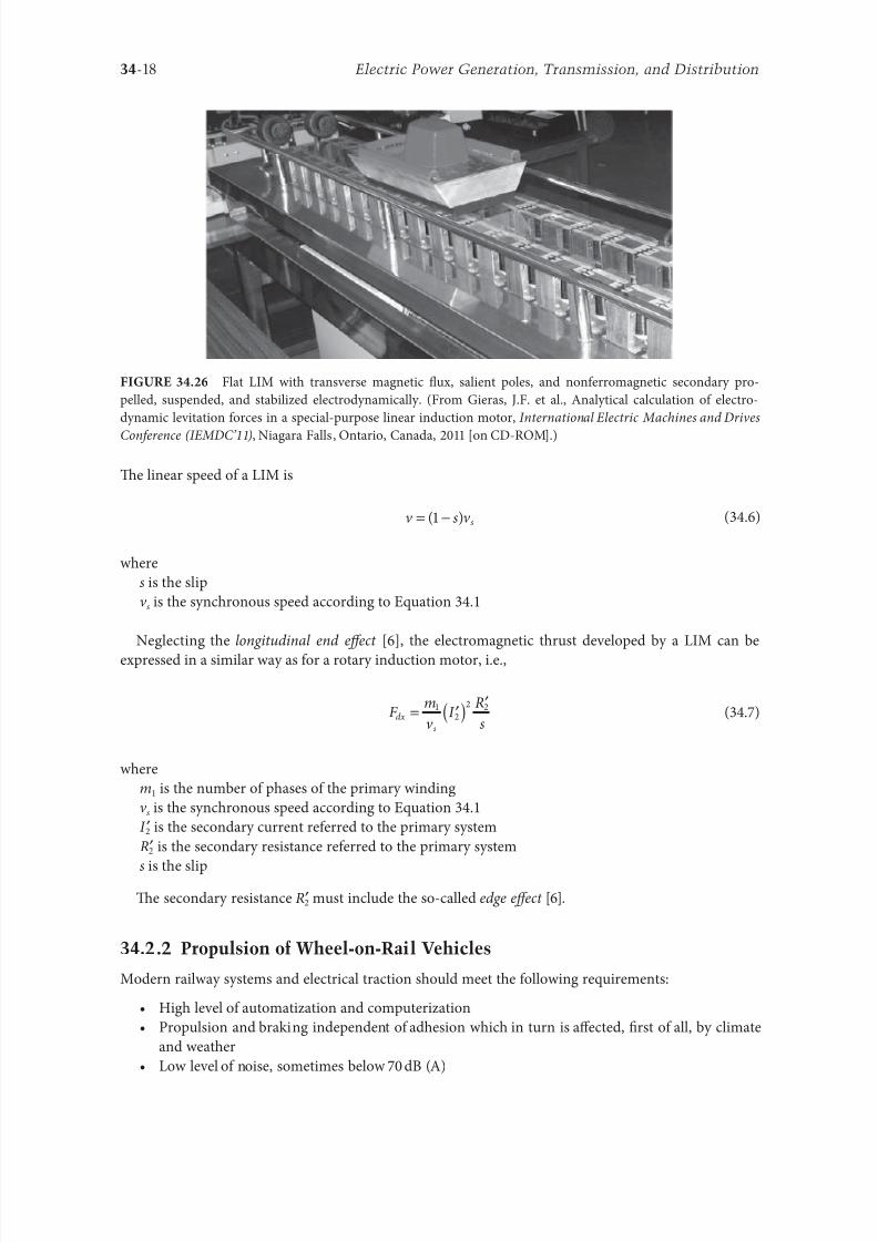
8102019 Power Handbook
httpslidepdfcomreaderfullpower-handbook 3343
34-18 Electric Power Generation Transmission and Distribution
Te linear speed o a LIM is
v s v s= minus( )1 (346)
where
s is the slip
v s is the synchronous speed according to Equation 341
Neglecting the longitudinal end effect [6] the electromagnetic thrust developed by a LIM can be
expressed in a similar way as or a rotary induction motor ie
F
m
v I
R
sdx
s
= prime( ) prime1
2
2 2
(347)
where
m1 is the number o phases o the primary winding
v s is the synchronous speed according to Equation 341
primeI 2 is the secondary current reerred to the primary system
primeR2 is the secondary resistance reerred to the primary system
s is the slip
Te secondary resistance primeR2 must include the so-called edge effect [6]
3422 Propulsion of Wheel-on-Rail Vehicles
Modern railway systems and electrical traction should meet the ollowing requirements
bull High level o automatization and computerization
bull Propulsion and braking independent o adhesion which in turn is affected 1047297rst o all by climate
and weather
bull Low level o noise sometimes below 70 dB (A)
Flat LIM with transverse magnetic 1047298ux salient poles and nonerromagnetic secondary pro-
pelled suspended and stabilized electrodynamically (From Gieras JF et al Analytical calculation o electro-
dynamic levitation orces in a special-purpose linear induction motor International Electric Machines and Drives
Conerence (IEMDCrsquo11) Niagara Falls Ontario Canada 2011 [on CD-ROM])
8102019 Power Handbook
httpslidepdfcomreaderfullpower-handbook 3443
34-19Linear Electric Motors
bull Ability to cope with high slopes at least 6 and sharp bends with radius o curvature less than 20 m
bull No pollution to natural environment and landscape
bull High reliability
Te congestion problems o big cities should be solved by creating collective transport orms that can be
implemented without affecting a highly populated city For example there are many cities in Italy where
the historical center has remained the same since the Renaissance A heavy railway might be a com-
pletely wrong solution and have a notable impact on the city planning An adequate solution might be
a light railway a people mover with transport capacity o 10000ndash20000 passengers per hour to replace
the traditional transport nets and to integrate the existing railway nets
All the requirements mentioned earlier can be met by using LIMs as propulsion machines Replacing
electrical rotary motors with linear motors in traction drives (electrical locomotives) generally does
not require new tracks but only their adjustment to linear drives Single-sided LIMs (Figure 3427a and b)
are best since the normal attractive orce o these can strengthen the adhesion o wheels and rails
Te air gap is rom 10 to 15 mm Most requently the motor car has two LIMs with short primaries
(Figure 3427a) assembled in series Te double-layer secondary consists o a solid back iron and an Al
cap and is located between the rails Cables or computer communication with the vehicle and quite
ofen collectors or electrical energy delivery to the vehicle are located along the track Tree-phaseLIMs are ed rom variable-voltage variable-requency (VVVF) voltage-source inverters A linear pro-
pulsion system o wheel-on-rail vehicles allows more 1047298exibility (Figure 3428) reducing noise on bends
and wear o the wheels and rails
Double-sided LIMs (Figure 3427c and d) have ound very limited application due to the technical
difficulty o eliminating aults caused by bends in the secondary with primary cores on either side It is
more difficult to keep a small and uniorm air gap in double-sided LIMs than that in single-sided LIMs
Te LIM-driven wheel-on-rail vehicles are built or low velocities ie less than 100 kmh and or
short routes ie less than 50 km (urban transit systems and short-distance trains) At present LIM-
driven trains operate in oronto and Vancouver BC Canada in Detroit MI (Figure 3429) okyo
(Figure 3430) and Osaka Japan and Kuala Lumpur Malaysia
(a) (b)
(c) (d)
LIM-driven wheel-on-rail cars (a) single-sided LIM with short primary mounted on the undercar-
riage (b) single-sided LIM with short secondary mounted on the undercarriage (c) double-sided LIM with short pri-
mary mounted on the undercarriage and (d) double-sided LIM with short secondary mounted on the undercarriage
8102019 Power Handbook
httpslidepdfcomreaderfullpower-handbook 3543
34-20 Electric Power Generation Transmission and Distribution
(a) (b)
Te undercarriage o a wheel-on-rail vehicle (a) rotary motor propulsion and (b) LIM propulsion
Detroit people mover driven by single-sided LIMs
oei Oedo subway line in okyo driven by single-sided LIMs
8102019 Power Handbook
httpslidepdfcomreaderfullpower-handbook 3643
34-21Linear Electric Motors
Te design data o some single-sided traction LIMs are presented in able 347 and double-sided trac-
tion LIMs in able 348
343 Variable Reluctance Motors
Te simplest construction o a variable reluctance LSM or linear reluctance motor (LRM) is that shown
in Figure 3418 with DC excitation winding being removed However the thrust o such a motor wouldbe low as the ratio o d -axis permeance to q-axis permeance is low Better perormance can be obtained
when using 1047298ux barriers [18] or steel laminations [15] o make 1047298ux barriers any nonerromagnetic
materials can be used o obtain high permeance (low reluctance) in the d -axis and low permeance in
the q-axis steel laminations should be oriented in such a way as to create high permeance or the d -axis
magnetic 1047298ux
Figure 3431a shows a variable reluctance platen with 1047298ux barriers and Figure 3431b shows how to
arrange steel laminations to obtain different reluctances in the d - and q-axes Te platen can be com-
posed o segments the length o which is equal to the pole pitchτ Each segment consists o semicircular
lamellas cut out rom electrotechnical sheet A 1047297lling or example epoxy resin is used to make the seg-
ment rigid and robust By putting the segments together a platen o any desired length can be obtained
Design Data o Single-Sided Tree-Phase LIMs or Propulsion o Vehicles
Quantity
LIM
UnitJLMDR ICS KU CIGG GEC
Pullout thrust at requency given
in the ollowing F x
125 90 35 17 07 kN
Input requency 200 400 250 400 600 Hz
Rated phase current V 1 2750 4650 1300 2000 2000 A
Number o poles 2 p 8 6 4 6 4 mdash
Number o turns per phase N 1 128 96 128 108 48 mdash
Equivalent diameter o conductor d 1 mdash 893 528 1115 81 mm
Number o parallel conductors mdash 1 mdash 19 1 mdash
Effective width o primary core Li 023 0216 029 0101 01715 m
Pole pitch τ 027 02868 030 025 020 m
Length o single end connection l e mdash 03483 mdash 02955 03685 m
Coil pitch wc 0225 01673 025 01944 01555 m
Air gap g 150 126 120 150 182 mm
Number o slots z 1( primez 1) 96(106) 72(79) 48(58) 54(61) 36(43) mdash
Width o slot b11 mdash 156 170 150 1308 mm
Width o slot opening b14 mdash 156 mdash 1044 1308 mm
Depth o slot h11 mdash 530 380 3421 6147 mm
Height o yoke h1 y mdash 436 393 7163 500 mm
Conductivity o back iron at 20degC σFe mdash 446 952 446 512 times106 Sm
Conductivity o Al cap at 20degC σ Al mdash 300 303 323 215 times106 Sm
Width o back iron w 03 024 03 0111 01715 m
Tickness o back iron hsec 190 125 250 254 474 mm
Tickness o Al cap d 50 45 50 45(25) 32 mm
Tickness o Al cap behind Fe core t ov 50 170 50 127 32 mm
Width o Al cap 030 032 040 0201 02985 m
JLMDR Japanese Linear Motor Driven Railcar Japan ICS Intermediate Capacity ransit System Canada KU
Kyushu University LIM Japan CIGG Canadian Inst o Guided Ground ransport Canada GEC General
Electric Company United States (z 1 ) is the number o hal 1047297lled slots
8102019 Power Handbook
httpslidepdfcomreaderfullpower-handbook 3743
34-22 Electric Power Generation Transmission and Distribution
344 Stepping Motors
A linear stepping motor has a concentrated armature winding wound on salient poles and PM excitation
rail or variable reluctance platen Te thrust is generated as an action o the armature magnetic 1047298ux and
PM 1047298ux (active platen) or the armature magnetic 1047298ux and salient erromagnetic poles (variable reluc-
tance platen) Stepping motors have no position eedback
Design Data o Double-Sided Tree-Phase LIMs or Propulsion
o Vehicles
Quantity
LIM
UnitGEC LIMVR
Maximum thrust at input requency F x given in the ollowing 085 1668 kN
Input requency 600 1730 Hz
Input phase current I 1 2000 20000 A
Number o poles 2 p 4 10 mdash
Number o turns per phase N 1 144 100 mdash
Diameter o conductor d 1 075 110 mm
Effective width o primary core Li 00869 0254 m
Pole pitch τ 01795 03556 m
Coil pitch wc 005 005 m
Number o slots z 1( primez 1) 36(45) 150(160) mdash
Width o slot b11 137 160 mm
Width o slot opening b14 137 mdash mm
Depth o slot h1 630 mdash mm
Height o yoke h1 y 239 mdash mm
Width o tooth c1 200 77 mm
Resultant air gap 2 g + d 381 38075 mm
Air gap g 2 times 127 2 times 111 mm
Tickness o secondary d 127 15875(hollow) mm
Effective thickness o Al secondary 127 72 mm
Width o secondary w ge03046 mdash m
Conductivity o Al cap at 20degC σ Al asymp2434 asymp240 times106 Sm
GEC General Electric Company United States LIMVR LIM Research Vehicle
Pueblo CO United States (z 1 ) is the number o hal 1047297lled slots
(a) (b)
q q d d d q d q d d
Laminations
τ τ τ τ
Epoxy resin
Variable reluctance LSMs with (a) 1047298ux barriers and (b) steel laminations
8102019 Power Handbook
httpslidepdfcomreaderfullpower-handbook 3843
8102019 Power Handbook
httpslidepdfcomreaderfullpower-handbook 3943
34-24 Electric Power Generation Transmission and Distribution
Tis value is different or ull-step and microstepping drives Te maximum startndashstop speed is the
maximum speed that can be used when starting or stopping the motor without ramping that does not
cause the motor to all out o synchronism or lose steps Te maximum speed is the maximum linear
speed that can be achieved without the motor stalling or alling out o synchronism Te maximum
load mass is the maximum allowable mass applied to the orcer against the scale that does not result in
mechanical damage Te ull-step resolution is the position increment obtained when the currents are
switched rom one winding to the next winding Tis is the typical resolution obtained with ul l-step
drives and it is strictly a unction o the motor construction Te microstepping resolution is the position
increment obtained when the ull-step resolution is divided electronically by proportioning the currents
in the two windings Tis resolution is typically 10ndash250 times smaller than the ull-step resolution [13]
HLSMs are regarded as an excellent solution to positioning systems that require a high accuracy
and rapid acceleration With a microprocessor controlled microstepping mode a smooth operation with
standard resolution o a ew hundred stepsmm can be obtained Te advantages such as high efficiencyhigh throughput mechanical simplicity high reliability precise open-loop operation and low inertia
o the system have made these kind o motors more and more attractive in such applications as actory
automation high speed positioning computer peripherals acsimile machines numerically controlled
machine tools automated medical equipment automated laboratory equipment and welding robots
Tis motor is especially suitable or machine tools printers plotters and computer-controlled material
handling in which a high positioning accuracy and repeatability are the key problems
When two or our orcers mounted at 90deg and a special grooved platen (ldquowaffle platerdquo) are used the
xndashy motion (two DOFs) in a single plane is obtained (Figure 3434)
Speci1047297cation data o the xndashy HLSMs manuactured by Normag Northern Magnetics Inc Santa
Clarita CA are given in able 3410
PM linear stepping motors (Photo courtesy o okyo Aircraf Instrument Co Ltd okyo Japan)
8102019 Power Handbook
httpslidepdfcomreaderfullpower-handbook 4043
34-25Linear Electric Motors
345 Switched Reluctance Motors
Te topology o a linear switched reluctance motor is similar to that o a stepping motor with variable
reluctance platen In addition it is equipped with position sensors Te turn-on and turn-off instant o
the input current is synchronized with the position o the moving part Te thrust is very sensitive to
the turn-on and turn-off instant
In the case o a linear stepping or linear switched reluctance motor the speed v o the moving part is
v v s sw= = τ
(348)
where
sw is the undamental switching requency in one armature phase winding
τ is the pole pitch o the reaction rail
For a rotary stepping or switched reluctance motor sw = 2 pr n where 2 pr is the number o rotor poles and
n is rotational speed in revs
A linear switched reluctance motor has a doubly salient magnetic circuit with a polyphase winding
on the armature Longitudinal and transverse 1047298ux designs are shown in Figure 3435 A linear switched
reluctance motor allows precise speed and position-controlled linear motion at low speeds and is not sub-
ject to design constraints (minimum speed limited by minimum easible pole pitch) o linear AC motors
x
y
12
3
4
1
1
2
2
HLSM with a our-unit orcer to obtain the xndashy motion 1 orcers or the x -direction 2 orcers
or the y -direction 3 platen 4 air pressure
Data o xndashy HLSMs Manuactured by Normag Northern Magnetics Inc
Santa Clarita CA
Parameter 4XY0602-2-0 4XY2002-2-0 4XY2004-2-0 4XY2504-2-0
Number o orcer units per axis 1 1 2 2
Number o phases 2 2 2(4) 2(4)Static thrust N 133 400 980 1330
Trust at 1 ms N 111 311 712 980
Normal attractive orce N 1600 4000 14400 18000
Resistance per phase Ω 29 33 16 19
Inductance per phase mH 15 40 20 23
Input phase current A 20 20 40 40
Air gap mm 002
Maximum temperature degC 110
Mass kg 32 072 20 15
Repeatability mm 000254
Resolution mm 000254
Bearing type Air
8102019 Power Handbook
httpslidepdfcomreaderfullpower-handbook 4143
34-26 Electric Power Generation Transmission and Distribution
346 Linear Positioning Stages
Linear motors are now playing a key role in advanced precision linear positioning Linear precision posi-
tioning systems can be classi1047297ed into open-loop systems with HLSMs and closed-loop servo systems
with LSMs LBMs or LIMs
A PM LSMndashdriven positioning stage is shown in Figure 3436 A stationary base is made o Al steel
ceramic or granite plate It provides a stable precise and 1047298at platorm to which all stationary position-
ing components are attached Te base o the stage is attached to the host system with the aid o mount-
ing screws
Te moving table accommodates all moving positioning components o achieve maximum accelera-
tion the mass o the moving table should be as small as possible and usually Al is used as a lightweight
material A number o mounting holes on the moving table is necessary to 1047297x the payload to the mount-
ing table
Linear bearing rails provide a precise guidance to the moving table A minimum o one bearing rail
is required Linear ball bearing or air bearings are attached to each rail
Te armature o a linear motor is astened to the moving table and reaction rail (PM excitation sys-tem) is built in the base between the rails (Figure 3436)
A linear encoder is needed to obtain precise control o position o the table velocity and acceleration
Te read head o the encoder is attached to the moving table
(a) (b)
3
3
221
1
Linear switched reluctance motor con1047297gurations (a) longitudinal 1047298ux design and (b) transverse
1047298ux design 1 armature winding 2 armature stack 3 platen
12
3
5
4
7
6
8
Linear positioning stage driven by PM LBM 1 base 2 moving table 3 armature o LBM 4 PMs
5 linear bearing 6 encoder 7 cable carrier 8 limit switch (Courtesy o Normag Santa Clarita CA)
8102019 Power Handbook
httpslidepdfcomreaderfullpower-handbook 4243
34-27Linear Electric Motors
Noncontact limit switches ixed to the base provide an overtravel protection and init ial homing
A cable carrier accommodates and routes electrical cables between the moving table and stationary
connector box 1047297xed to the base
An HLSM-driven linear precision stage is o similar construction Instead o PMs between bearing
rails it has a variable reluctance platen HLSMs usually need air bearings and in addition to the electri-
cal cables an air hose between air bearings and the compressor is requiredLinear positioning stages are used in semiconductor technology electronic assembly quality assur-
ance laser cutting optical scanning water jet cutting gantry systems (x y z stages) color printers
plotters and Cartesian coordinate robotics
References
1 Anorad Linear Motors Inormation Brochure Anorad Hauppauge New York 2007 wwwanoradcom
2 Boldea I and Nasar SA Linear Motion Electromagnetic Systems John Wiley amp Sons New York 1985
3 Boldea I and Nasar SA Linear Electric Actuators and Generators Cambridge University Press
New York 2005
4 Compumotor Digiplan Positioning Control Systems and Drives Parker Hanni1047297n CorporationRohnert Park CA 2011
5 Everes W Henneberger G Wunderlich H and Selig A A linear homopolar motor or a trans-
portation system 2nd International Symposium on Linear Drives or Industry Applications (LDIArsquo98)
okyo Japan 1998 pp 46ndash49
6 Gieras JF Linear Induction Drives Clarendon Press Oxord UK 1994
7 Gieras JF Status o linear motors in the United States International Symposium on Linear Drives
or Industry Applications (LDIArsquo03) Birmingham UK 2003 pp 169ndash176
8 Gieras JF Gientkowski Z Mews J and Splawski P Analytical calculation o electrodynamic
levitation orces in a special-purpose linear induction motor International Electric Machines and
Drives Conerence (IEMDCrsquo11) Niagara Falls Ontario Canada 2011 [on CD-ROM]
9 Gieras JF Piech ZJ and omczuk BZ Linear Synchronous Motors ransportation and Automation Systems aylor amp Francis (CRC Press) Boca Raton FL 2011
10 Hoang E Ahmed AHB and Lucidarme J Switching 1047298ux permanent magnet polyphase syn-
chronous machines 7th European Conerence on Power Electronics and Applications (EPErsquo97)
Vol 3 rondheim Norway 1977 pp 903ndash908
11 Kollmorgen Linear Motors Aim to Cut Cost o Semiconductors and Electronics Manuacture
Kollmorgen Radord VA 1997
12 Laithwaite ER A History o Linear Electric Motors Macmillan London UK 1987
13 Linear Step Motor Inormation Brochure okyo Aircraf Instrument Co Ltd okyo Japan
1998
14 LinMot Design Manual Sulzer Electronics Ltd Zuumlrich Switzerland 1999
15 Locci N and Marongiu I Modelling and testing a new linear reluctance motor InternationalConerence on Electrical Machines (ICEMrsquo92) Vol 2 Manchester UK 1992 pp 706ndash710
16 Rauch SE and Johnson LJ Design principles o 1047298ux-switch alternators AIEE rans Part III
74(12) 1261ndash1269 1955
17 Rosenmayr M Casat Glavitsch A and Stemmler H SwissmetromdashPower supply or a high-
power-propulsion system with short stator linear motors 15th International Conerence on
Magnetically Levitated Systems and Linear Drives Maglevrsquo98 Mount Fuji Yamanashi Japan 1998
pp 280ndash286
18 Sanada M Morimoto S and akeda Y Reluctance equalization design o multi 1047298ux barrier con-
struction or linear synchronous reluctance motors 2nd International Symposium on Linear Drives
or Industrial Applications (LDIArsquo98) okyo Japan 1998 pp 259ndash262
8102019 Power Handbook
httpslidepdfcomreaderfullpower-handbook 4343
34-28 Electric Power Generation Transmission and Distribution
19 Seok-Myeong J and Sang-Sub J Design and analysis o the linear homopolar synchronous motor
or integrated magnetic propulsion and suspension 2nd International Symposium on Linear Drives
or Industrial Applications (LDIArsquo98) okyo Japan 1998 pp 74ndash77
20 Synchronous Linear Motor 1FN6 Te Electrical Gear Rack Siemens AG Industry Sector Drive
echnologies Motion Control Erlangen Germany 2008
21 Yamada H Handbook o Linear Motor Applications (in Japanese) Kogyo Chosaki Publishing Cookyo Japan 1986
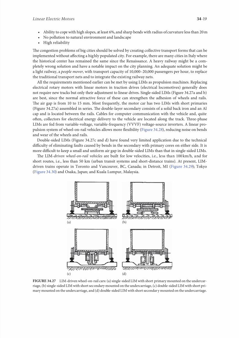
8102019 Power Handbook
httpslidepdfcomreaderfullpower-handbook 3443
34-19Linear Electric Motors
bull Ability to cope with high slopes at least 6 and sharp bends with radius o curvature less than 20 m
bull No pollution to natural environment and landscape
bull High reliability
Te congestion problems o big cities should be solved by creating collective transport orms that can be
implemented without affecting a highly populated city For example there are many cities in Italy where
the historical center has remained the same since the Renaissance A heavy railway might be a com-
pletely wrong solution and have a notable impact on the city planning An adequate solution might be
a light railway a people mover with transport capacity o 10000ndash20000 passengers per hour to replace
the traditional transport nets and to integrate the existing railway nets
All the requirements mentioned earlier can be met by using LIMs as propulsion machines Replacing
electrical rotary motors with linear motors in traction drives (electrical locomotives) generally does
not require new tracks but only their adjustment to linear drives Single-sided LIMs (Figure 3427a and b)
are best since the normal attractive orce o these can strengthen the adhesion o wheels and rails
Te air gap is rom 10 to 15 mm Most requently the motor car has two LIMs with short primaries
(Figure 3427a) assembled in series Te double-layer secondary consists o a solid back iron and an Al
cap and is located between the rails Cables or computer communication with the vehicle and quite
ofen collectors or electrical energy delivery to the vehicle are located along the track Tree-phaseLIMs are ed rom variable-voltage variable-requency (VVVF) voltage-source inverters A linear pro-
pulsion system o wheel-on-rail vehicles allows more 1047298exibility (Figure 3428) reducing noise on bends
and wear o the wheels and rails
Double-sided LIMs (Figure 3427c and d) have ound very limited application due to the technical
difficulty o eliminating aults caused by bends in the secondary with primary cores on either side It is
more difficult to keep a small and uniorm air gap in double-sided LIMs than that in single-sided LIMs
Te LIM-driven wheel-on-rail vehicles are built or low velocities ie less than 100 kmh and or
short routes ie less than 50 km (urban transit systems and short-distance trains) At present LIM-
driven trains operate in oronto and Vancouver BC Canada in Detroit MI (Figure 3429) okyo
(Figure 3430) and Osaka Japan and Kuala Lumpur Malaysia
(a) (b)
(c) (d)
LIM-driven wheel-on-rail cars (a) single-sided LIM with short primary mounted on the undercar-
riage (b) single-sided LIM with short secondary mounted on the undercarriage (c) double-sided LIM with short pri-
mary mounted on the undercarriage and (d) double-sided LIM with short secondary mounted on the undercarriage
8102019 Power Handbook
httpslidepdfcomreaderfullpower-handbook 3543
34-20 Electric Power Generation Transmission and Distribution
(a) (b)
Te undercarriage o a wheel-on-rail vehicle (a) rotary motor propulsion and (b) LIM propulsion
Detroit people mover driven by single-sided LIMs
oei Oedo subway line in okyo driven by single-sided LIMs
8102019 Power Handbook
httpslidepdfcomreaderfullpower-handbook 3643
34-21Linear Electric Motors
Te design data o some single-sided traction LIMs are presented in able 347 and double-sided trac-
tion LIMs in able 348
343 Variable Reluctance Motors
Te simplest construction o a variable reluctance LSM or linear reluctance motor (LRM) is that shown
in Figure 3418 with DC excitation winding being removed However the thrust o such a motor wouldbe low as the ratio o d -axis permeance to q-axis permeance is low Better perormance can be obtained
when using 1047298ux barriers [18] or steel laminations [15] o make 1047298ux barriers any nonerromagnetic
materials can be used o obtain high permeance (low reluctance) in the d -axis and low permeance in
the q-axis steel laminations should be oriented in such a way as to create high permeance or the d -axis
magnetic 1047298ux
Figure 3431a shows a variable reluctance platen with 1047298ux barriers and Figure 3431b shows how to
arrange steel laminations to obtain different reluctances in the d - and q-axes Te platen can be com-
posed o segments the length o which is equal to the pole pitchτ Each segment consists o semicircular
lamellas cut out rom electrotechnical sheet A 1047297lling or example epoxy resin is used to make the seg-
ment rigid and robust By putting the segments together a platen o any desired length can be obtained
Design Data o Single-Sided Tree-Phase LIMs or Propulsion o Vehicles
Quantity
LIM
UnitJLMDR ICS KU CIGG GEC
Pullout thrust at requency given
in the ollowing F x
125 90 35 17 07 kN
Input requency 200 400 250 400 600 Hz
Rated phase current V 1 2750 4650 1300 2000 2000 A
Number o poles 2 p 8 6 4 6 4 mdash
Number o turns per phase N 1 128 96 128 108 48 mdash
Equivalent diameter o conductor d 1 mdash 893 528 1115 81 mm
Number o parallel conductors mdash 1 mdash 19 1 mdash
Effective width o primary core Li 023 0216 029 0101 01715 m
Pole pitch τ 027 02868 030 025 020 m
Length o single end connection l e mdash 03483 mdash 02955 03685 m
Coil pitch wc 0225 01673 025 01944 01555 m
Air gap g 150 126 120 150 182 mm
Number o slots z 1( primez 1) 96(106) 72(79) 48(58) 54(61) 36(43) mdash
Width o slot b11 mdash 156 170 150 1308 mm
Width o slot opening b14 mdash 156 mdash 1044 1308 mm
Depth o slot h11 mdash 530 380 3421 6147 mm
Height o yoke h1 y mdash 436 393 7163 500 mm
Conductivity o back iron at 20degC σFe mdash 446 952 446 512 times106 Sm
Conductivity o Al cap at 20degC σ Al mdash 300 303 323 215 times106 Sm
Width o back iron w 03 024 03 0111 01715 m
Tickness o back iron hsec 190 125 250 254 474 mm
Tickness o Al cap d 50 45 50 45(25) 32 mm
Tickness o Al cap behind Fe core t ov 50 170 50 127 32 mm
Width o Al cap 030 032 040 0201 02985 m
JLMDR Japanese Linear Motor Driven Railcar Japan ICS Intermediate Capacity ransit System Canada KU
Kyushu University LIM Japan CIGG Canadian Inst o Guided Ground ransport Canada GEC General
Electric Company United States (z 1 ) is the number o hal 1047297lled slots
8102019 Power Handbook
httpslidepdfcomreaderfullpower-handbook 3743
34-22 Electric Power Generation Transmission and Distribution
344 Stepping Motors
A linear stepping motor has a concentrated armature winding wound on salient poles and PM excitation
rail or variable reluctance platen Te thrust is generated as an action o the armature magnetic 1047298ux and
PM 1047298ux (active platen) or the armature magnetic 1047298ux and salient erromagnetic poles (variable reluc-
tance platen) Stepping motors have no position eedback
Design Data o Double-Sided Tree-Phase LIMs or Propulsion
o Vehicles
Quantity
LIM
UnitGEC LIMVR
Maximum thrust at input requency F x given in the ollowing 085 1668 kN
Input requency 600 1730 Hz
Input phase current I 1 2000 20000 A
Number o poles 2 p 4 10 mdash
Number o turns per phase N 1 144 100 mdash
Diameter o conductor d 1 075 110 mm
Effective width o primary core Li 00869 0254 m
Pole pitch τ 01795 03556 m
Coil pitch wc 005 005 m
Number o slots z 1( primez 1) 36(45) 150(160) mdash
Width o slot b11 137 160 mm
Width o slot opening b14 137 mdash mm
Depth o slot h1 630 mdash mm
Height o yoke h1 y 239 mdash mm
Width o tooth c1 200 77 mm
Resultant air gap 2 g + d 381 38075 mm
Air gap g 2 times 127 2 times 111 mm
Tickness o secondary d 127 15875(hollow) mm
Effective thickness o Al secondary 127 72 mm
Width o secondary w ge03046 mdash m
Conductivity o Al cap at 20degC σ Al asymp2434 asymp240 times106 Sm
GEC General Electric Company United States LIMVR LIM Research Vehicle
Pueblo CO United States (z 1 ) is the number o hal 1047297lled slots
(a) (b)
q q d d d q d q d d
Laminations
τ τ τ τ
Epoxy resin
Variable reluctance LSMs with (a) 1047298ux barriers and (b) steel laminations
8102019 Power Handbook
httpslidepdfcomreaderfullpower-handbook 3843
8102019 Power Handbook
httpslidepdfcomreaderfullpower-handbook 3943
34-24 Electric Power Generation Transmission and Distribution
Tis value is different or ull-step and microstepping drives Te maximum startndashstop speed is the
maximum speed that can be used when starting or stopping the motor without ramping that does not
cause the motor to all out o synchronism or lose steps Te maximum speed is the maximum linear
speed that can be achieved without the motor stalling or alling out o synchronism Te maximum
load mass is the maximum allowable mass applied to the orcer against the scale that does not result in
mechanical damage Te ull-step resolution is the position increment obtained when the currents are
switched rom one winding to the next winding Tis is the typical resolution obtained with ul l-step
drives and it is strictly a unction o the motor construction Te microstepping resolution is the position
increment obtained when the ull-step resolution is divided electronically by proportioning the currents
in the two windings Tis resolution is typically 10ndash250 times smaller than the ull-step resolution [13]
HLSMs are regarded as an excellent solution to positioning systems that require a high accuracy
and rapid acceleration With a microprocessor controlled microstepping mode a smooth operation with
standard resolution o a ew hundred stepsmm can be obtained Te advantages such as high efficiencyhigh throughput mechanical simplicity high reliability precise open-loop operation and low inertia
o the system have made these kind o motors more and more attractive in such applications as actory
automation high speed positioning computer peripherals acsimile machines numerically controlled
machine tools automated medical equipment automated laboratory equipment and welding robots
Tis motor is especially suitable or machine tools printers plotters and computer-controlled material
handling in which a high positioning accuracy and repeatability are the key problems
When two or our orcers mounted at 90deg and a special grooved platen (ldquowaffle platerdquo) are used the
xndashy motion (two DOFs) in a single plane is obtained (Figure 3434)
Speci1047297cation data o the xndashy HLSMs manuactured by Normag Northern Magnetics Inc Santa
Clarita CA are given in able 3410
PM linear stepping motors (Photo courtesy o okyo Aircraf Instrument Co Ltd okyo Japan)
8102019 Power Handbook
httpslidepdfcomreaderfullpower-handbook 4043
34-25Linear Electric Motors
345 Switched Reluctance Motors
Te topology o a linear switched reluctance motor is similar to that o a stepping motor with variable
reluctance platen In addition it is equipped with position sensors Te turn-on and turn-off instant o
the input current is synchronized with the position o the moving part Te thrust is very sensitive to
the turn-on and turn-off instant
In the case o a linear stepping or linear switched reluctance motor the speed v o the moving part is
v v s sw= = τ
(348)
where
sw is the undamental switching requency in one armature phase winding
τ is the pole pitch o the reaction rail
For a rotary stepping or switched reluctance motor sw = 2 pr n where 2 pr is the number o rotor poles and
n is rotational speed in revs
A linear switched reluctance motor has a doubly salient magnetic circuit with a polyphase winding
on the armature Longitudinal and transverse 1047298ux designs are shown in Figure 3435 A linear switched
reluctance motor allows precise speed and position-controlled linear motion at low speeds and is not sub-
ject to design constraints (minimum speed limited by minimum easible pole pitch) o linear AC motors
x
y
12
3
4
1
1
2
2
HLSM with a our-unit orcer to obtain the xndashy motion 1 orcers or the x -direction 2 orcers
or the y -direction 3 platen 4 air pressure
Data o xndashy HLSMs Manuactured by Normag Northern Magnetics Inc
Santa Clarita CA
Parameter 4XY0602-2-0 4XY2002-2-0 4XY2004-2-0 4XY2504-2-0
Number o orcer units per axis 1 1 2 2
Number o phases 2 2 2(4) 2(4)Static thrust N 133 400 980 1330
Trust at 1 ms N 111 311 712 980
Normal attractive orce N 1600 4000 14400 18000
Resistance per phase Ω 29 33 16 19
Inductance per phase mH 15 40 20 23
Input phase current A 20 20 40 40
Air gap mm 002
Maximum temperature degC 110
Mass kg 32 072 20 15
Repeatability mm 000254
Resolution mm 000254
Bearing type Air
8102019 Power Handbook
httpslidepdfcomreaderfullpower-handbook 4143
34-26 Electric Power Generation Transmission and Distribution
346 Linear Positioning Stages
Linear motors are now playing a key role in advanced precision linear positioning Linear precision posi-
tioning systems can be classi1047297ed into open-loop systems with HLSMs and closed-loop servo systems
with LSMs LBMs or LIMs
A PM LSMndashdriven positioning stage is shown in Figure 3436 A stationary base is made o Al steel
ceramic or granite plate It provides a stable precise and 1047298at platorm to which all stationary position-
ing components are attached Te base o the stage is attached to the host system with the aid o mount-
ing screws
Te moving table accommodates all moving positioning components o achieve maximum accelera-
tion the mass o the moving table should be as small as possible and usually Al is used as a lightweight
material A number o mounting holes on the moving table is necessary to 1047297x the payload to the mount-
ing table
Linear bearing rails provide a precise guidance to the moving table A minimum o one bearing rail
is required Linear ball bearing or air bearings are attached to each rail
Te armature o a linear motor is astened to the moving table and reaction rail (PM excitation sys-tem) is built in the base between the rails (Figure 3436)
A linear encoder is needed to obtain precise control o position o the table velocity and acceleration
Te read head o the encoder is attached to the moving table
(a) (b)
3
3
221
1
Linear switched reluctance motor con1047297gurations (a) longitudinal 1047298ux design and (b) transverse
1047298ux design 1 armature winding 2 armature stack 3 platen
12
3
5
4
7
6
8
Linear positioning stage driven by PM LBM 1 base 2 moving table 3 armature o LBM 4 PMs
5 linear bearing 6 encoder 7 cable carrier 8 limit switch (Courtesy o Normag Santa Clarita CA)
8102019 Power Handbook
httpslidepdfcomreaderfullpower-handbook 4243
34-27Linear Electric Motors
Noncontact limit switches ixed to the base provide an overtravel protection and init ial homing
A cable carrier accommodates and routes electrical cables between the moving table and stationary
connector box 1047297xed to the base
An HLSM-driven linear precision stage is o similar construction Instead o PMs between bearing
rails it has a variable reluctance platen HLSMs usually need air bearings and in addition to the electri-
cal cables an air hose between air bearings and the compressor is requiredLinear positioning stages are used in semiconductor technology electronic assembly quality assur-
ance laser cutting optical scanning water jet cutting gantry systems (x y z stages) color printers
plotters and Cartesian coordinate robotics
References
1 Anorad Linear Motors Inormation Brochure Anorad Hauppauge New York 2007 wwwanoradcom
2 Boldea I and Nasar SA Linear Motion Electromagnetic Systems John Wiley amp Sons New York 1985
3 Boldea I and Nasar SA Linear Electric Actuators and Generators Cambridge University Press
New York 2005
4 Compumotor Digiplan Positioning Control Systems and Drives Parker Hanni1047297n CorporationRohnert Park CA 2011
5 Everes W Henneberger G Wunderlich H and Selig A A linear homopolar motor or a trans-
portation system 2nd International Symposium on Linear Drives or Industry Applications (LDIArsquo98)
okyo Japan 1998 pp 46ndash49
6 Gieras JF Linear Induction Drives Clarendon Press Oxord UK 1994
7 Gieras JF Status o linear motors in the United States International Symposium on Linear Drives
or Industry Applications (LDIArsquo03) Birmingham UK 2003 pp 169ndash176
8 Gieras JF Gientkowski Z Mews J and Splawski P Analytical calculation o electrodynamic
levitation orces in a special-purpose linear induction motor International Electric Machines and
Drives Conerence (IEMDCrsquo11) Niagara Falls Ontario Canada 2011 [on CD-ROM]
9 Gieras JF Piech ZJ and omczuk BZ Linear Synchronous Motors ransportation and Automation Systems aylor amp Francis (CRC Press) Boca Raton FL 2011
10 Hoang E Ahmed AHB and Lucidarme J Switching 1047298ux permanent magnet polyphase syn-
chronous machines 7th European Conerence on Power Electronics and Applications (EPErsquo97)
Vol 3 rondheim Norway 1977 pp 903ndash908
11 Kollmorgen Linear Motors Aim to Cut Cost o Semiconductors and Electronics Manuacture
Kollmorgen Radord VA 1997
12 Laithwaite ER A History o Linear Electric Motors Macmillan London UK 1987
13 Linear Step Motor Inormation Brochure okyo Aircraf Instrument Co Ltd okyo Japan
1998
14 LinMot Design Manual Sulzer Electronics Ltd Zuumlrich Switzerland 1999
15 Locci N and Marongiu I Modelling and testing a new linear reluctance motor InternationalConerence on Electrical Machines (ICEMrsquo92) Vol 2 Manchester UK 1992 pp 706ndash710
16 Rauch SE and Johnson LJ Design principles o 1047298ux-switch alternators AIEE rans Part III
74(12) 1261ndash1269 1955
17 Rosenmayr M Casat Glavitsch A and Stemmler H SwissmetromdashPower supply or a high-
power-propulsion system with short stator linear motors 15th International Conerence on
Magnetically Levitated Systems and Linear Drives Maglevrsquo98 Mount Fuji Yamanashi Japan 1998
pp 280ndash286
18 Sanada M Morimoto S and akeda Y Reluctance equalization design o multi 1047298ux barrier con-
struction or linear synchronous reluctance motors 2nd International Symposium on Linear Drives
or Industrial Applications (LDIArsquo98) okyo Japan 1998 pp 259ndash262
8102019 Power Handbook
httpslidepdfcomreaderfullpower-handbook 4343
34-28 Electric Power Generation Transmission and Distribution
19 Seok-Myeong J and Sang-Sub J Design and analysis o the linear homopolar synchronous motor
or integrated magnetic propulsion and suspension 2nd International Symposium on Linear Drives
or Industrial Applications (LDIArsquo98) okyo Japan 1998 pp 74ndash77
20 Synchronous Linear Motor 1FN6 Te Electrical Gear Rack Siemens AG Industry Sector Drive
echnologies Motion Control Erlangen Germany 2008
21 Yamada H Handbook o Linear Motor Applications (in Japanese) Kogyo Chosaki Publishing Cookyo Japan 1986
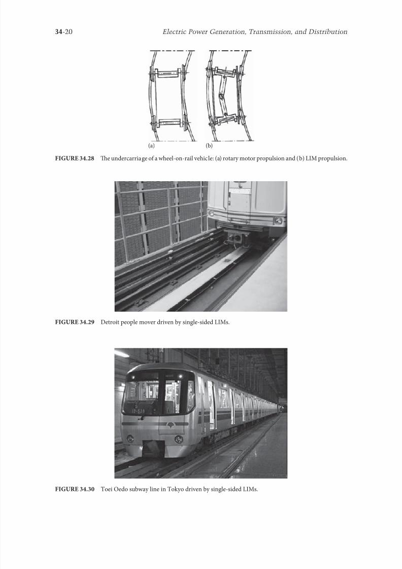
8102019 Power Handbook
httpslidepdfcomreaderfullpower-handbook 3543
34-20 Electric Power Generation Transmission and Distribution
(a) (b)
Te undercarriage o a wheel-on-rail vehicle (a) rotary motor propulsion and (b) LIM propulsion
Detroit people mover driven by single-sided LIMs
oei Oedo subway line in okyo driven by single-sided LIMs
8102019 Power Handbook
httpslidepdfcomreaderfullpower-handbook 3643
34-21Linear Electric Motors
Te design data o some single-sided traction LIMs are presented in able 347 and double-sided trac-
tion LIMs in able 348
343 Variable Reluctance Motors
Te simplest construction o a variable reluctance LSM or linear reluctance motor (LRM) is that shown
in Figure 3418 with DC excitation winding being removed However the thrust o such a motor wouldbe low as the ratio o d -axis permeance to q-axis permeance is low Better perormance can be obtained
when using 1047298ux barriers [18] or steel laminations [15] o make 1047298ux barriers any nonerromagnetic
materials can be used o obtain high permeance (low reluctance) in the d -axis and low permeance in
the q-axis steel laminations should be oriented in such a way as to create high permeance or the d -axis
magnetic 1047298ux
Figure 3431a shows a variable reluctance platen with 1047298ux barriers and Figure 3431b shows how to
arrange steel laminations to obtain different reluctances in the d - and q-axes Te platen can be com-
posed o segments the length o which is equal to the pole pitchτ Each segment consists o semicircular
lamellas cut out rom electrotechnical sheet A 1047297lling or example epoxy resin is used to make the seg-
ment rigid and robust By putting the segments together a platen o any desired length can be obtained
Design Data o Single-Sided Tree-Phase LIMs or Propulsion o Vehicles
Quantity
LIM
UnitJLMDR ICS KU CIGG GEC
Pullout thrust at requency given
in the ollowing F x
125 90 35 17 07 kN
Input requency 200 400 250 400 600 Hz
Rated phase current V 1 2750 4650 1300 2000 2000 A
Number o poles 2 p 8 6 4 6 4 mdash
Number o turns per phase N 1 128 96 128 108 48 mdash
Equivalent diameter o conductor d 1 mdash 893 528 1115 81 mm
Number o parallel conductors mdash 1 mdash 19 1 mdash
Effective width o primary core Li 023 0216 029 0101 01715 m
Pole pitch τ 027 02868 030 025 020 m
Length o single end connection l e mdash 03483 mdash 02955 03685 m
Coil pitch wc 0225 01673 025 01944 01555 m
Air gap g 150 126 120 150 182 mm
Number o slots z 1( primez 1) 96(106) 72(79) 48(58) 54(61) 36(43) mdash
Width o slot b11 mdash 156 170 150 1308 mm
Width o slot opening b14 mdash 156 mdash 1044 1308 mm
Depth o slot h11 mdash 530 380 3421 6147 mm
Height o yoke h1 y mdash 436 393 7163 500 mm
Conductivity o back iron at 20degC σFe mdash 446 952 446 512 times106 Sm
Conductivity o Al cap at 20degC σ Al mdash 300 303 323 215 times106 Sm
Width o back iron w 03 024 03 0111 01715 m
Tickness o back iron hsec 190 125 250 254 474 mm
Tickness o Al cap d 50 45 50 45(25) 32 mm
Tickness o Al cap behind Fe core t ov 50 170 50 127 32 mm
Width o Al cap 030 032 040 0201 02985 m
JLMDR Japanese Linear Motor Driven Railcar Japan ICS Intermediate Capacity ransit System Canada KU
Kyushu University LIM Japan CIGG Canadian Inst o Guided Ground ransport Canada GEC General
Electric Company United States (z 1 ) is the number o hal 1047297lled slots
8102019 Power Handbook
httpslidepdfcomreaderfullpower-handbook 3743
34-22 Electric Power Generation Transmission and Distribution
344 Stepping Motors
A linear stepping motor has a concentrated armature winding wound on salient poles and PM excitation
rail or variable reluctance platen Te thrust is generated as an action o the armature magnetic 1047298ux and
PM 1047298ux (active platen) or the armature magnetic 1047298ux and salient erromagnetic poles (variable reluc-
tance platen) Stepping motors have no position eedback
Design Data o Double-Sided Tree-Phase LIMs or Propulsion
o Vehicles
Quantity
LIM
UnitGEC LIMVR
Maximum thrust at input requency F x given in the ollowing 085 1668 kN
Input requency 600 1730 Hz
Input phase current I 1 2000 20000 A
Number o poles 2 p 4 10 mdash
Number o turns per phase N 1 144 100 mdash
Diameter o conductor d 1 075 110 mm
Effective width o primary core Li 00869 0254 m
Pole pitch τ 01795 03556 m
Coil pitch wc 005 005 m
Number o slots z 1( primez 1) 36(45) 150(160) mdash
Width o slot b11 137 160 mm
Width o slot opening b14 137 mdash mm
Depth o slot h1 630 mdash mm
Height o yoke h1 y 239 mdash mm
Width o tooth c1 200 77 mm
Resultant air gap 2 g + d 381 38075 mm
Air gap g 2 times 127 2 times 111 mm
Tickness o secondary d 127 15875(hollow) mm
Effective thickness o Al secondary 127 72 mm
Width o secondary w ge03046 mdash m
Conductivity o Al cap at 20degC σ Al asymp2434 asymp240 times106 Sm
GEC General Electric Company United States LIMVR LIM Research Vehicle
Pueblo CO United States (z 1 ) is the number o hal 1047297lled slots
(a) (b)
q q d d d q d q d d
Laminations
τ τ τ τ
Epoxy resin
Variable reluctance LSMs with (a) 1047298ux barriers and (b) steel laminations
8102019 Power Handbook
httpslidepdfcomreaderfullpower-handbook 3843
8102019 Power Handbook
httpslidepdfcomreaderfullpower-handbook 3943
34-24 Electric Power Generation Transmission and Distribution
Tis value is different or ull-step and microstepping drives Te maximum startndashstop speed is the
maximum speed that can be used when starting or stopping the motor without ramping that does not
cause the motor to all out o synchronism or lose steps Te maximum speed is the maximum linear
speed that can be achieved without the motor stalling or alling out o synchronism Te maximum
load mass is the maximum allowable mass applied to the orcer against the scale that does not result in
mechanical damage Te ull-step resolution is the position increment obtained when the currents are
switched rom one winding to the next winding Tis is the typical resolution obtained with ul l-step
drives and it is strictly a unction o the motor construction Te microstepping resolution is the position
increment obtained when the ull-step resolution is divided electronically by proportioning the currents
in the two windings Tis resolution is typically 10ndash250 times smaller than the ull-step resolution [13]
HLSMs are regarded as an excellent solution to positioning systems that require a high accuracy
and rapid acceleration With a microprocessor controlled microstepping mode a smooth operation with
standard resolution o a ew hundred stepsmm can be obtained Te advantages such as high efficiencyhigh throughput mechanical simplicity high reliability precise open-loop operation and low inertia
o the system have made these kind o motors more and more attractive in such applications as actory
automation high speed positioning computer peripherals acsimile machines numerically controlled
machine tools automated medical equipment automated laboratory equipment and welding robots
Tis motor is especially suitable or machine tools printers plotters and computer-controlled material
handling in which a high positioning accuracy and repeatability are the key problems
When two or our orcers mounted at 90deg and a special grooved platen (ldquowaffle platerdquo) are used the
xndashy motion (two DOFs) in a single plane is obtained (Figure 3434)
Speci1047297cation data o the xndashy HLSMs manuactured by Normag Northern Magnetics Inc Santa
Clarita CA are given in able 3410
PM linear stepping motors (Photo courtesy o okyo Aircraf Instrument Co Ltd okyo Japan)
8102019 Power Handbook
httpslidepdfcomreaderfullpower-handbook 4043
34-25Linear Electric Motors
345 Switched Reluctance Motors
Te topology o a linear switched reluctance motor is similar to that o a stepping motor with variable
reluctance platen In addition it is equipped with position sensors Te turn-on and turn-off instant o
the input current is synchronized with the position o the moving part Te thrust is very sensitive to
the turn-on and turn-off instant
In the case o a linear stepping or linear switched reluctance motor the speed v o the moving part is
v v s sw= = τ
(348)
where
sw is the undamental switching requency in one armature phase winding
τ is the pole pitch o the reaction rail
For a rotary stepping or switched reluctance motor sw = 2 pr n where 2 pr is the number o rotor poles and
n is rotational speed in revs
A linear switched reluctance motor has a doubly salient magnetic circuit with a polyphase winding
on the armature Longitudinal and transverse 1047298ux designs are shown in Figure 3435 A linear switched
reluctance motor allows precise speed and position-controlled linear motion at low speeds and is not sub-
ject to design constraints (minimum speed limited by minimum easible pole pitch) o linear AC motors
x
y
12
3
4
1
1
2
2
HLSM with a our-unit orcer to obtain the xndashy motion 1 orcers or the x -direction 2 orcers
or the y -direction 3 platen 4 air pressure
Data o xndashy HLSMs Manuactured by Normag Northern Magnetics Inc
Santa Clarita CA
Parameter 4XY0602-2-0 4XY2002-2-0 4XY2004-2-0 4XY2504-2-0
Number o orcer units per axis 1 1 2 2
Number o phases 2 2 2(4) 2(4)Static thrust N 133 400 980 1330
Trust at 1 ms N 111 311 712 980
Normal attractive orce N 1600 4000 14400 18000
Resistance per phase Ω 29 33 16 19
Inductance per phase mH 15 40 20 23
Input phase current A 20 20 40 40
Air gap mm 002
Maximum temperature degC 110
Mass kg 32 072 20 15
Repeatability mm 000254
Resolution mm 000254
Bearing type Air
8102019 Power Handbook
httpslidepdfcomreaderfullpower-handbook 4143
34-26 Electric Power Generation Transmission and Distribution
346 Linear Positioning Stages
Linear motors are now playing a key role in advanced precision linear positioning Linear precision posi-
tioning systems can be classi1047297ed into open-loop systems with HLSMs and closed-loop servo systems
with LSMs LBMs or LIMs
A PM LSMndashdriven positioning stage is shown in Figure 3436 A stationary base is made o Al steel
ceramic or granite plate It provides a stable precise and 1047298at platorm to which all stationary position-
ing components are attached Te base o the stage is attached to the host system with the aid o mount-
ing screws
Te moving table accommodates all moving positioning components o achieve maximum accelera-
tion the mass o the moving table should be as small as possible and usually Al is used as a lightweight
material A number o mounting holes on the moving table is necessary to 1047297x the payload to the mount-
ing table
Linear bearing rails provide a precise guidance to the moving table A minimum o one bearing rail
is required Linear ball bearing or air bearings are attached to each rail
Te armature o a linear motor is astened to the moving table and reaction rail (PM excitation sys-tem) is built in the base between the rails (Figure 3436)
A linear encoder is needed to obtain precise control o position o the table velocity and acceleration
Te read head o the encoder is attached to the moving table
(a) (b)
3
3
221
1
Linear switched reluctance motor con1047297gurations (a) longitudinal 1047298ux design and (b) transverse
1047298ux design 1 armature winding 2 armature stack 3 platen
12
3
5
4
7
6
8
Linear positioning stage driven by PM LBM 1 base 2 moving table 3 armature o LBM 4 PMs
5 linear bearing 6 encoder 7 cable carrier 8 limit switch (Courtesy o Normag Santa Clarita CA)
8102019 Power Handbook
httpslidepdfcomreaderfullpower-handbook 4243
34-27Linear Electric Motors
Noncontact limit switches ixed to the base provide an overtravel protection and init ial homing
A cable carrier accommodates and routes electrical cables between the moving table and stationary
connector box 1047297xed to the base
An HLSM-driven linear precision stage is o similar construction Instead o PMs between bearing
rails it has a variable reluctance platen HLSMs usually need air bearings and in addition to the electri-
cal cables an air hose between air bearings and the compressor is requiredLinear positioning stages are used in semiconductor technology electronic assembly quality assur-
ance laser cutting optical scanning water jet cutting gantry systems (x y z stages) color printers
plotters and Cartesian coordinate robotics
References
1 Anorad Linear Motors Inormation Brochure Anorad Hauppauge New York 2007 wwwanoradcom
2 Boldea I and Nasar SA Linear Motion Electromagnetic Systems John Wiley amp Sons New York 1985
3 Boldea I and Nasar SA Linear Electric Actuators and Generators Cambridge University Press
New York 2005
4 Compumotor Digiplan Positioning Control Systems and Drives Parker Hanni1047297n CorporationRohnert Park CA 2011
5 Everes W Henneberger G Wunderlich H and Selig A A linear homopolar motor or a trans-
portation system 2nd International Symposium on Linear Drives or Industry Applications (LDIArsquo98)
okyo Japan 1998 pp 46ndash49
6 Gieras JF Linear Induction Drives Clarendon Press Oxord UK 1994
7 Gieras JF Status o linear motors in the United States International Symposium on Linear Drives
or Industry Applications (LDIArsquo03) Birmingham UK 2003 pp 169ndash176
8 Gieras JF Gientkowski Z Mews J and Splawski P Analytical calculation o electrodynamic
levitation orces in a special-purpose linear induction motor International Electric Machines and
Drives Conerence (IEMDCrsquo11) Niagara Falls Ontario Canada 2011 [on CD-ROM]
9 Gieras JF Piech ZJ and omczuk BZ Linear Synchronous Motors ransportation and Automation Systems aylor amp Francis (CRC Press) Boca Raton FL 2011
10 Hoang E Ahmed AHB and Lucidarme J Switching 1047298ux permanent magnet polyphase syn-
chronous machines 7th European Conerence on Power Electronics and Applications (EPErsquo97)
Vol 3 rondheim Norway 1977 pp 903ndash908
11 Kollmorgen Linear Motors Aim to Cut Cost o Semiconductors and Electronics Manuacture
Kollmorgen Radord VA 1997
12 Laithwaite ER A History o Linear Electric Motors Macmillan London UK 1987
13 Linear Step Motor Inormation Brochure okyo Aircraf Instrument Co Ltd okyo Japan
1998
14 LinMot Design Manual Sulzer Electronics Ltd Zuumlrich Switzerland 1999
15 Locci N and Marongiu I Modelling and testing a new linear reluctance motor InternationalConerence on Electrical Machines (ICEMrsquo92) Vol 2 Manchester UK 1992 pp 706ndash710
16 Rauch SE and Johnson LJ Design principles o 1047298ux-switch alternators AIEE rans Part III
74(12) 1261ndash1269 1955
17 Rosenmayr M Casat Glavitsch A and Stemmler H SwissmetromdashPower supply or a high-
power-propulsion system with short stator linear motors 15th International Conerence on
Magnetically Levitated Systems and Linear Drives Maglevrsquo98 Mount Fuji Yamanashi Japan 1998
pp 280ndash286
18 Sanada M Morimoto S and akeda Y Reluctance equalization design o multi 1047298ux barrier con-
struction or linear synchronous reluctance motors 2nd International Symposium on Linear Drives
or Industrial Applications (LDIArsquo98) okyo Japan 1998 pp 259ndash262
8102019 Power Handbook
httpslidepdfcomreaderfullpower-handbook 4343
34-28 Electric Power Generation Transmission and Distribution
19 Seok-Myeong J and Sang-Sub J Design and analysis o the linear homopolar synchronous motor
or integrated magnetic propulsion and suspension 2nd International Symposium on Linear Drives
or Industrial Applications (LDIArsquo98) okyo Japan 1998 pp 74ndash77
20 Synchronous Linear Motor 1FN6 Te Electrical Gear Rack Siemens AG Industry Sector Drive
echnologies Motion Control Erlangen Germany 2008
21 Yamada H Handbook o Linear Motor Applications (in Japanese) Kogyo Chosaki Publishing Cookyo Japan 1986
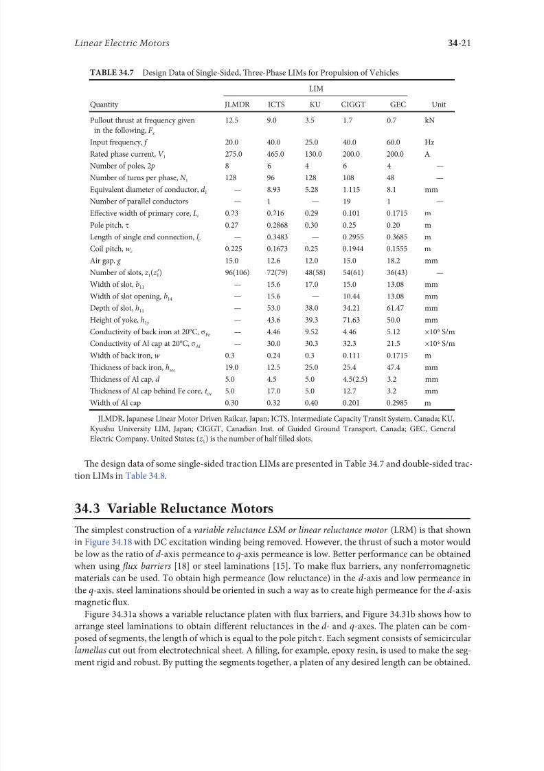
8102019 Power Handbook
httpslidepdfcomreaderfullpower-handbook 3643
34-21Linear Electric Motors
Te design data o some single-sided traction LIMs are presented in able 347 and double-sided trac-
tion LIMs in able 348
343 Variable Reluctance Motors
Te simplest construction o a variable reluctance LSM or linear reluctance motor (LRM) is that shown
in Figure 3418 with DC excitation winding being removed However the thrust o such a motor wouldbe low as the ratio o d -axis permeance to q-axis permeance is low Better perormance can be obtained
when using 1047298ux barriers [18] or steel laminations [15] o make 1047298ux barriers any nonerromagnetic
materials can be used o obtain high permeance (low reluctance) in the d -axis and low permeance in
the q-axis steel laminations should be oriented in such a way as to create high permeance or the d -axis
magnetic 1047298ux
Figure 3431a shows a variable reluctance platen with 1047298ux barriers and Figure 3431b shows how to
arrange steel laminations to obtain different reluctances in the d - and q-axes Te platen can be com-
posed o segments the length o which is equal to the pole pitchτ Each segment consists o semicircular
lamellas cut out rom electrotechnical sheet A 1047297lling or example epoxy resin is used to make the seg-
ment rigid and robust By putting the segments together a platen o any desired length can be obtained
Design Data o Single-Sided Tree-Phase LIMs or Propulsion o Vehicles
Quantity
LIM
UnitJLMDR ICS KU CIGG GEC
Pullout thrust at requency given
in the ollowing F x
125 90 35 17 07 kN
Input requency 200 400 250 400 600 Hz
Rated phase current V 1 2750 4650 1300 2000 2000 A
Number o poles 2 p 8 6 4 6 4 mdash
Number o turns per phase N 1 128 96 128 108 48 mdash
Equivalent diameter o conductor d 1 mdash 893 528 1115 81 mm
Number o parallel conductors mdash 1 mdash 19 1 mdash
Effective width o primary core Li 023 0216 029 0101 01715 m
Pole pitch τ 027 02868 030 025 020 m
Length o single end connection l e mdash 03483 mdash 02955 03685 m
Coil pitch wc 0225 01673 025 01944 01555 m
Air gap g 150 126 120 150 182 mm
Number o slots z 1( primez 1) 96(106) 72(79) 48(58) 54(61) 36(43) mdash
Width o slot b11 mdash 156 170 150 1308 mm
Width o slot opening b14 mdash 156 mdash 1044 1308 mm
Depth o slot h11 mdash 530 380 3421 6147 mm
Height o yoke h1 y mdash 436 393 7163 500 mm
Conductivity o back iron at 20degC σFe mdash 446 952 446 512 times106 Sm
Conductivity o Al cap at 20degC σ Al mdash 300 303 323 215 times106 Sm
Width o back iron w 03 024 03 0111 01715 m
Tickness o back iron hsec 190 125 250 254 474 mm
Tickness o Al cap d 50 45 50 45(25) 32 mm
Tickness o Al cap behind Fe core t ov 50 170 50 127 32 mm
Width o Al cap 030 032 040 0201 02985 m
JLMDR Japanese Linear Motor Driven Railcar Japan ICS Intermediate Capacity ransit System Canada KU
Kyushu University LIM Japan CIGG Canadian Inst o Guided Ground ransport Canada GEC General
Electric Company United States (z 1 ) is the number o hal 1047297lled slots
8102019 Power Handbook
httpslidepdfcomreaderfullpower-handbook 3743
34-22 Electric Power Generation Transmission and Distribution
344 Stepping Motors
A linear stepping motor has a concentrated armature winding wound on salient poles and PM excitation
rail or variable reluctance platen Te thrust is generated as an action o the armature magnetic 1047298ux and
PM 1047298ux (active platen) or the armature magnetic 1047298ux and salient erromagnetic poles (variable reluc-
tance platen) Stepping motors have no position eedback
Design Data o Double-Sided Tree-Phase LIMs or Propulsion
o Vehicles
Quantity
LIM
UnitGEC LIMVR
Maximum thrust at input requency F x given in the ollowing 085 1668 kN
Input requency 600 1730 Hz
Input phase current I 1 2000 20000 A
Number o poles 2 p 4 10 mdash
Number o turns per phase N 1 144 100 mdash
Diameter o conductor d 1 075 110 mm
Effective width o primary core Li 00869 0254 m
Pole pitch τ 01795 03556 m
Coil pitch wc 005 005 m
Number o slots z 1( primez 1) 36(45) 150(160) mdash
Width o slot b11 137 160 mm
Width o slot opening b14 137 mdash mm
Depth o slot h1 630 mdash mm
Height o yoke h1 y 239 mdash mm
Width o tooth c1 200 77 mm
Resultant air gap 2 g + d 381 38075 mm
Air gap g 2 times 127 2 times 111 mm
Tickness o secondary d 127 15875(hollow) mm
Effective thickness o Al secondary 127 72 mm
Width o secondary w ge03046 mdash m
Conductivity o Al cap at 20degC σ Al asymp2434 asymp240 times106 Sm
GEC General Electric Company United States LIMVR LIM Research Vehicle
Pueblo CO United States (z 1 ) is the number o hal 1047297lled slots
(a) (b)
q q d d d q d q d d
Laminations
τ τ τ τ
Epoxy resin
Variable reluctance LSMs with (a) 1047298ux barriers and (b) steel laminations
8102019 Power Handbook
httpslidepdfcomreaderfullpower-handbook 3843
8102019 Power Handbook
httpslidepdfcomreaderfullpower-handbook 3943
34-24 Electric Power Generation Transmission and Distribution
Tis value is different or ull-step and microstepping drives Te maximum startndashstop speed is the
maximum speed that can be used when starting or stopping the motor without ramping that does not
cause the motor to all out o synchronism or lose steps Te maximum speed is the maximum linear
speed that can be achieved without the motor stalling or alling out o synchronism Te maximum
load mass is the maximum allowable mass applied to the orcer against the scale that does not result in
mechanical damage Te ull-step resolution is the position increment obtained when the currents are
switched rom one winding to the next winding Tis is the typical resolution obtained with ul l-step
drives and it is strictly a unction o the motor construction Te microstepping resolution is the position
increment obtained when the ull-step resolution is divided electronically by proportioning the currents
in the two windings Tis resolution is typically 10ndash250 times smaller than the ull-step resolution [13]
HLSMs are regarded as an excellent solution to positioning systems that require a high accuracy
and rapid acceleration With a microprocessor controlled microstepping mode a smooth operation with
standard resolution o a ew hundred stepsmm can be obtained Te advantages such as high efficiencyhigh throughput mechanical simplicity high reliability precise open-loop operation and low inertia
o the system have made these kind o motors more and more attractive in such applications as actory
automation high speed positioning computer peripherals acsimile machines numerically controlled
machine tools automated medical equipment automated laboratory equipment and welding robots
Tis motor is especially suitable or machine tools printers plotters and computer-controlled material
handling in which a high positioning accuracy and repeatability are the key problems
When two or our orcers mounted at 90deg and a special grooved platen (ldquowaffle platerdquo) are used the
xndashy motion (two DOFs) in a single plane is obtained (Figure 3434)
Speci1047297cation data o the xndashy HLSMs manuactured by Normag Northern Magnetics Inc Santa
Clarita CA are given in able 3410
PM linear stepping motors (Photo courtesy o okyo Aircraf Instrument Co Ltd okyo Japan)
8102019 Power Handbook
httpslidepdfcomreaderfullpower-handbook 4043
34-25Linear Electric Motors
345 Switched Reluctance Motors
Te topology o a linear switched reluctance motor is similar to that o a stepping motor with variable
reluctance platen In addition it is equipped with position sensors Te turn-on and turn-off instant o
the input current is synchronized with the position o the moving part Te thrust is very sensitive to
the turn-on and turn-off instant
In the case o a linear stepping or linear switched reluctance motor the speed v o the moving part is
v v s sw= = τ
(348)
where
sw is the undamental switching requency in one armature phase winding
τ is the pole pitch o the reaction rail
For a rotary stepping or switched reluctance motor sw = 2 pr n where 2 pr is the number o rotor poles and
n is rotational speed in revs
A linear switched reluctance motor has a doubly salient magnetic circuit with a polyphase winding
on the armature Longitudinal and transverse 1047298ux designs are shown in Figure 3435 A linear switched
reluctance motor allows precise speed and position-controlled linear motion at low speeds and is not sub-
ject to design constraints (minimum speed limited by minimum easible pole pitch) o linear AC motors
x
y
12
3
4
1
1
2
2
HLSM with a our-unit orcer to obtain the xndashy motion 1 orcers or the x -direction 2 orcers
or the y -direction 3 platen 4 air pressure
Data o xndashy HLSMs Manuactured by Normag Northern Magnetics Inc
Santa Clarita CA
Parameter 4XY0602-2-0 4XY2002-2-0 4XY2004-2-0 4XY2504-2-0
Number o orcer units per axis 1 1 2 2
Number o phases 2 2 2(4) 2(4)Static thrust N 133 400 980 1330
Trust at 1 ms N 111 311 712 980
Normal attractive orce N 1600 4000 14400 18000
Resistance per phase Ω 29 33 16 19
Inductance per phase mH 15 40 20 23
Input phase current A 20 20 40 40
Air gap mm 002
Maximum temperature degC 110
Mass kg 32 072 20 15
Repeatability mm 000254
Resolution mm 000254
Bearing type Air
8102019 Power Handbook
httpslidepdfcomreaderfullpower-handbook 4143
34-26 Electric Power Generation Transmission and Distribution
346 Linear Positioning Stages
Linear motors are now playing a key role in advanced precision linear positioning Linear precision posi-
tioning systems can be classi1047297ed into open-loop systems with HLSMs and closed-loop servo systems
with LSMs LBMs or LIMs
A PM LSMndashdriven positioning stage is shown in Figure 3436 A stationary base is made o Al steel
ceramic or granite plate It provides a stable precise and 1047298at platorm to which all stationary position-
ing components are attached Te base o the stage is attached to the host system with the aid o mount-
ing screws
Te moving table accommodates all moving positioning components o achieve maximum accelera-
tion the mass o the moving table should be as small as possible and usually Al is used as a lightweight
material A number o mounting holes on the moving table is necessary to 1047297x the payload to the mount-
ing table
Linear bearing rails provide a precise guidance to the moving table A minimum o one bearing rail
is required Linear ball bearing or air bearings are attached to each rail
Te armature o a linear motor is astened to the moving table and reaction rail (PM excitation sys-tem) is built in the base between the rails (Figure 3436)
A linear encoder is needed to obtain precise control o position o the table velocity and acceleration
Te read head o the encoder is attached to the moving table
(a) (b)
3
3
221
1
Linear switched reluctance motor con1047297gurations (a) longitudinal 1047298ux design and (b) transverse
1047298ux design 1 armature winding 2 armature stack 3 platen
12
3
5
4
7
6
8
Linear positioning stage driven by PM LBM 1 base 2 moving table 3 armature o LBM 4 PMs
5 linear bearing 6 encoder 7 cable carrier 8 limit switch (Courtesy o Normag Santa Clarita CA)
8102019 Power Handbook
httpslidepdfcomreaderfullpower-handbook 4243
34-27Linear Electric Motors
Noncontact limit switches ixed to the base provide an overtravel protection and init ial homing
A cable carrier accommodates and routes electrical cables between the moving table and stationary
connector box 1047297xed to the base
An HLSM-driven linear precision stage is o similar construction Instead o PMs between bearing
rails it has a variable reluctance platen HLSMs usually need air bearings and in addition to the electri-
cal cables an air hose between air bearings and the compressor is requiredLinear positioning stages are used in semiconductor technology electronic assembly quality assur-
ance laser cutting optical scanning water jet cutting gantry systems (x y z stages) color printers
plotters and Cartesian coordinate robotics
References
1 Anorad Linear Motors Inormation Brochure Anorad Hauppauge New York 2007 wwwanoradcom
2 Boldea I and Nasar SA Linear Motion Electromagnetic Systems John Wiley amp Sons New York 1985
3 Boldea I and Nasar SA Linear Electric Actuators and Generators Cambridge University Press
New York 2005
4 Compumotor Digiplan Positioning Control Systems and Drives Parker Hanni1047297n CorporationRohnert Park CA 2011
5 Everes W Henneberger G Wunderlich H and Selig A A linear homopolar motor or a trans-
portation system 2nd International Symposium on Linear Drives or Industry Applications (LDIArsquo98)
okyo Japan 1998 pp 46ndash49
6 Gieras JF Linear Induction Drives Clarendon Press Oxord UK 1994
7 Gieras JF Status o linear motors in the United States International Symposium on Linear Drives
or Industry Applications (LDIArsquo03) Birmingham UK 2003 pp 169ndash176
8 Gieras JF Gientkowski Z Mews J and Splawski P Analytical calculation o electrodynamic
levitation orces in a special-purpose linear induction motor International Electric Machines and
Drives Conerence (IEMDCrsquo11) Niagara Falls Ontario Canada 2011 [on CD-ROM]
9 Gieras JF Piech ZJ and omczuk BZ Linear Synchronous Motors ransportation and Automation Systems aylor amp Francis (CRC Press) Boca Raton FL 2011
10 Hoang E Ahmed AHB and Lucidarme J Switching 1047298ux permanent magnet polyphase syn-
chronous machines 7th European Conerence on Power Electronics and Applications (EPErsquo97)
Vol 3 rondheim Norway 1977 pp 903ndash908
11 Kollmorgen Linear Motors Aim to Cut Cost o Semiconductors and Electronics Manuacture
Kollmorgen Radord VA 1997
12 Laithwaite ER A History o Linear Electric Motors Macmillan London UK 1987
13 Linear Step Motor Inormation Brochure okyo Aircraf Instrument Co Ltd okyo Japan
1998
14 LinMot Design Manual Sulzer Electronics Ltd Zuumlrich Switzerland 1999
15 Locci N and Marongiu I Modelling and testing a new linear reluctance motor InternationalConerence on Electrical Machines (ICEMrsquo92) Vol 2 Manchester UK 1992 pp 706ndash710
16 Rauch SE and Johnson LJ Design principles o 1047298ux-switch alternators AIEE rans Part III
74(12) 1261ndash1269 1955
17 Rosenmayr M Casat Glavitsch A and Stemmler H SwissmetromdashPower supply or a high-
power-propulsion system with short stator linear motors 15th International Conerence on
Magnetically Levitated Systems and Linear Drives Maglevrsquo98 Mount Fuji Yamanashi Japan 1998
pp 280ndash286
18 Sanada M Morimoto S and akeda Y Reluctance equalization design o multi 1047298ux barrier con-
struction or linear synchronous reluctance motors 2nd International Symposium on Linear Drives
or Industrial Applications (LDIArsquo98) okyo Japan 1998 pp 259ndash262
8102019 Power Handbook
httpslidepdfcomreaderfullpower-handbook 4343
34-28 Electric Power Generation Transmission and Distribution
19 Seok-Myeong J and Sang-Sub J Design and analysis o the linear homopolar synchronous motor
or integrated magnetic propulsion and suspension 2nd International Symposium on Linear Drives
or Industrial Applications (LDIArsquo98) okyo Japan 1998 pp 74ndash77
20 Synchronous Linear Motor 1FN6 Te Electrical Gear Rack Siemens AG Industry Sector Drive
echnologies Motion Control Erlangen Germany 2008
21 Yamada H Handbook o Linear Motor Applications (in Japanese) Kogyo Chosaki Publishing Cookyo Japan 1986
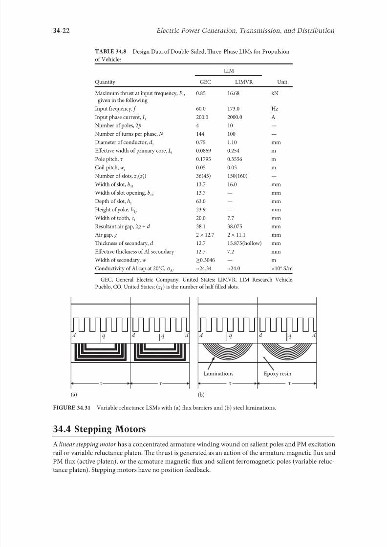
8102019 Power Handbook
httpslidepdfcomreaderfullpower-handbook 3743
34-22 Electric Power Generation Transmission and Distribution
344 Stepping Motors
A linear stepping motor has a concentrated armature winding wound on salient poles and PM excitation
rail or variable reluctance platen Te thrust is generated as an action o the armature magnetic 1047298ux and
PM 1047298ux (active platen) or the armature magnetic 1047298ux and salient erromagnetic poles (variable reluc-
tance platen) Stepping motors have no position eedback
Design Data o Double-Sided Tree-Phase LIMs or Propulsion
o Vehicles
Quantity
LIM
UnitGEC LIMVR
Maximum thrust at input requency F x given in the ollowing 085 1668 kN
Input requency 600 1730 Hz
Input phase current I 1 2000 20000 A
Number o poles 2 p 4 10 mdash
Number o turns per phase N 1 144 100 mdash
Diameter o conductor d 1 075 110 mm
Effective width o primary core Li 00869 0254 m
Pole pitch τ 01795 03556 m
Coil pitch wc 005 005 m
Number o slots z 1( primez 1) 36(45) 150(160) mdash
Width o slot b11 137 160 mm
Width o slot opening b14 137 mdash mm
Depth o slot h1 630 mdash mm
Height o yoke h1 y 239 mdash mm
Width o tooth c1 200 77 mm
Resultant air gap 2 g + d 381 38075 mm
Air gap g 2 times 127 2 times 111 mm
Tickness o secondary d 127 15875(hollow) mm
Effective thickness o Al secondary 127 72 mm
Width o secondary w ge03046 mdash m
Conductivity o Al cap at 20degC σ Al asymp2434 asymp240 times106 Sm
GEC General Electric Company United States LIMVR LIM Research Vehicle
Pueblo CO United States (z 1 ) is the number o hal 1047297lled slots
(a) (b)
q q d d d q d q d d
Laminations
τ τ τ τ
Epoxy resin
Variable reluctance LSMs with (a) 1047298ux barriers and (b) steel laminations
8102019 Power Handbook
httpslidepdfcomreaderfullpower-handbook 3843
8102019 Power Handbook
httpslidepdfcomreaderfullpower-handbook 3943
34-24 Electric Power Generation Transmission and Distribution
Tis value is different or ull-step and microstepping drives Te maximum startndashstop speed is the
maximum speed that can be used when starting or stopping the motor without ramping that does not
cause the motor to all out o synchronism or lose steps Te maximum speed is the maximum linear
speed that can be achieved without the motor stalling or alling out o synchronism Te maximum
load mass is the maximum allowable mass applied to the orcer against the scale that does not result in
mechanical damage Te ull-step resolution is the position increment obtained when the currents are
switched rom one winding to the next winding Tis is the typical resolution obtained with ul l-step
drives and it is strictly a unction o the motor construction Te microstepping resolution is the position
increment obtained when the ull-step resolution is divided electronically by proportioning the currents
in the two windings Tis resolution is typically 10ndash250 times smaller than the ull-step resolution [13]
HLSMs are regarded as an excellent solution to positioning systems that require a high accuracy
and rapid acceleration With a microprocessor controlled microstepping mode a smooth operation with
standard resolution o a ew hundred stepsmm can be obtained Te advantages such as high efficiencyhigh throughput mechanical simplicity high reliability precise open-loop operation and low inertia
o the system have made these kind o motors more and more attractive in such applications as actory
automation high speed positioning computer peripherals acsimile machines numerically controlled
machine tools automated medical equipment automated laboratory equipment and welding robots
Tis motor is especially suitable or machine tools printers plotters and computer-controlled material
handling in which a high positioning accuracy and repeatability are the key problems
When two or our orcers mounted at 90deg and a special grooved platen (ldquowaffle platerdquo) are used the
xndashy motion (two DOFs) in a single plane is obtained (Figure 3434)
Speci1047297cation data o the xndashy HLSMs manuactured by Normag Northern Magnetics Inc Santa
Clarita CA are given in able 3410
PM linear stepping motors (Photo courtesy o okyo Aircraf Instrument Co Ltd okyo Japan)
8102019 Power Handbook
httpslidepdfcomreaderfullpower-handbook 4043
34-25Linear Electric Motors
345 Switched Reluctance Motors
Te topology o a linear switched reluctance motor is similar to that o a stepping motor with variable
reluctance platen In addition it is equipped with position sensors Te turn-on and turn-off instant o
the input current is synchronized with the position o the moving part Te thrust is very sensitive to
the turn-on and turn-off instant
In the case o a linear stepping or linear switched reluctance motor the speed v o the moving part is
v v s sw= = τ
(348)
where
sw is the undamental switching requency in one armature phase winding
τ is the pole pitch o the reaction rail
For a rotary stepping or switched reluctance motor sw = 2 pr n where 2 pr is the number o rotor poles and
n is rotational speed in revs
A linear switched reluctance motor has a doubly salient magnetic circuit with a polyphase winding
on the armature Longitudinal and transverse 1047298ux designs are shown in Figure 3435 A linear switched
reluctance motor allows precise speed and position-controlled linear motion at low speeds and is not sub-
ject to design constraints (minimum speed limited by minimum easible pole pitch) o linear AC motors
x
y
12
3
4
1
1
2
2
HLSM with a our-unit orcer to obtain the xndashy motion 1 orcers or the x -direction 2 orcers
or the y -direction 3 platen 4 air pressure
Data o xndashy HLSMs Manuactured by Normag Northern Magnetics Inc
Santa Clarita CA
Parameter 4XY0602-2-0 4XY2002-2-0 4XY2004-2-0 4XY2504-2-0
Number o orcer units per axis 1 1 2 2
Number o phases 2 2 2(4) 2(4)Static thrust N 133 400 980 1330
Trust at 1 ms N 111 311 712 980
Normal attractive orce N 1600 4000 14400 18000
Resistance per phase Ω 29 33 16 19
Inductance per phase mH 15 40 20 23
Input phase current A 20 20 40 40
Air gap mm 002
Maximum temperature degC 110
Mass kg 32 072 20 15
Repeatability mm 000254
Resolution mm 000254
Bearing type Air
8102019 Power Handbook
httpslidepdfcomreaderfullpower-handbook 4143
34-26 Electric Power Generation Transmission and Distribution
346 Linear Positioning Stages
Linear motors are now playing a key role in advanced precision linear positioning Linear precision posi-
tioning systems can be classi1047297ed into open-loop systems with HLSMs and closed-loop servo systems
with LSMs LBMs or LIMs
A PM LSMndashdriven positioning stage is shown in Figure 3436 A stationary base is made o Al steel
ceramic or granite plate It provides a stable precise and 1047298at platorm to which all stationary position-
ing components are attached Te base o the stage is attached to the host system with the aid o mount-
ing screws
Te moving table accommodates all moving positioning components o achieve maximum accelera-
tion the mass o the moving table should be as small as possible and usually Al is used as a lightweight
material A number o mounting holes on the moving table is necessary to 1047297x the payload to the mount-
ing table
Linear bearing rails provide a precise guidance to the moving table A minimum o one bearing rail
is required Linear ball bearing or air bearings are attached to each rail
Te armature o a linear motor is astened to the moving table and reaction rail (PM excitation sys-tem) is built in the base between the rails (Figure 3436)
A linear encoder is needed to obtain precise control o position o the table velocity and acceleration
Te read head o the encoder is attached to the moving table
(a) (b)
3
3
221
1
Linear switched reluctance motor con1047297gurations (a) longitudinal 1047298ux design and (b) transverse
1047298ux design 1 armature winding 2 armature stack 3 platen
12
3
5
4
7
6
8
Linear positioning stage driven by PM LBM 1 base 2 moving table 3 armature o LBM 4 PMs
5 linear bearing 6 encoder 7 cable carrier 8 limit switch (Courtesy o Normag Santa Clarita CA)
8102019 Power Handbook
httpslidepdfcomreaderfullpower-handbook 4243
34-27Linear Electric Motors
Noncontact limit switches ixed to the base provide an overtravel protection and init ial homing
A cable carrier accommodates and routes electrical cables between the moving table and stationary
connector box 1047297xed to the base
An HLSM-driven linear precision stage is o similar construction Instead o PMs between bearing
rails it has a variable reluctance platen HLSMs usually need air bearings and in addition to the electri-
cal cables an air hose between air bearings and the compressor is requiredLinear positioning stages are used in semiconductor technology electronic assembly quality assur-
ance laser cutting optical scanning water jet cutting gantry systems (x y z stages) color printers
plotters and Cartesian coordinate robotics
References
1 Anorad Linear Motors Inormation Brochure Anorad Hauppauge New York 2007 wwwanoradcom
2 Boldea I and Nasar SA Linear Motion Electromagnetic Systems John Wiley amp Sons New York 1985
3 Boldea I and Nasar SA Linear Electric Actuators and Generators Cambridge University Press
New York 2005
4 Compumotor Digiplan Positioning Control Systems and Drives Parker Hanni1047297n CorporationRohnert Park CA 2011
5 Everes W Henneberger G Wunderlich H and Selig A A linear homopolar motor or a trans-
portation system 2nd International Symposium on Linear Drives or Industry Applications (LDIArsquo98)
okyo Japan 1998 pp 46ndash49
6 Gieras JF Linear Induction Drives Clarendon Press Oxord UK 1994
7 Gieras JF Status o linear motors in the United States International Symposium on Linear Drives
or Industry Applications (LDIArsquo03) Birmingham UK 2003 pp 169ndash176
8 Gieras JF Gientkowski Z Mews J and Splawski P Analytical calculation o electrodynamic
levitation orces in a special-purpose linear induction motor International Electric Machines and
Drives Conerence (IEMDCrsquo11) Niagara Falls Ontario Canada 2011 [on CD-ROM]
9 Gieras JF Piech ZJ and omczuk BZ Linear Synchronous Motors ransportation and Automation Systems aylor amp Francis (CRC Press) Boca Raton FL 2011
10 Hoang E Ahmed AHB and Lucidarme J Switching 1047298ux permanent magnet polyphase syn-
chronous machines 7th European Conerence on Power Electronics and Applications (EPErsquo97)
Vol 3 rondheim Norway 1977 pp 903ndash908
11 Kollmorgen Linear Motors Aim to Cut Cost o Semiconductors and Electronics Manuacture
Kollmorgen Radord VA 1997
12 Laithwaite ER A History o Linear Electric Motors Macmillan London UK 1987
13 Linear Step Motor Inormation Brochure okyo Aircraf Instrument Co Ltd okyo Japan
1998
14 LinMot Design Manual Sulzer Electronics Ltd Zuumlrich Switzerland 1999
15 Locci N and Marongiu I Modelling and testing a new linear reluctance motor InternationalConerence on Electrical Machines (ICEMrsquo92) Vol 2 Manchester UK 1992 pp 706ndash710
16 Rauch SE and Johnson LJ Design principles o 1047298ux-switch alternators AIEE rans Part III
74(12) 1261ndash1269 1955
17 Rosenmayr M Casat Glavitsch A and Stemmler H SwissmetromdashPower supply or a high-
power-propulsion system with short stator linear motors 15th International Conerence on
Magnetically Levitated Systems and Linear Drives Maglevrsquo98 Mount Fuji Yamanashi Japan 1998
pp 280ndash286
18 Sanada M Morimoto S and akeda Y Reluctance equalization design o multi 1047298ux barrier con-
struction or linear synchronous reluctance motors 2nd International Symposium on Linear Drives
or Industrial Applications (LDIArsquo98) okyo Japan 1998 pp 259ndash262
8102019 Power Handbook
httpslidepdfcomreaderfullpower-handbook 4343
34-28 Electric Power Generation Transmission and Distribution
19 Seok-Myeong J and Sang-Sub J Design and analysis o the linear homopolar synchronous motor
or integrated magnetic propulsion and suspension 2nd International Symposium on Linear Drives
or Industrial Applications (LDIArsquo98) okyo Japan 1998 pp 74ndash77
20 Synchronous Linear Motor 1FN6 Te Electrical Gear Rack Siemens AG Industry Sector Drive
echnologies Motion Control Erlangen Germany 2008
21 Yamada H Handbook o Linear Motor Applications (in Japanese) Kogyo Chosaki Publishing Cookyo Japan 1986
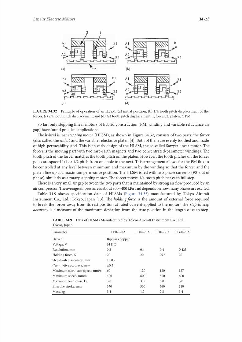
8102019 Power Handbook
httpslidepdfcomreaderfullpower-handbook 3843
8102019 Power Handbook
httpslidepdfcomreaderfullpower-handbook 3943
34-24 Electric Power Generation Transmission and Distribution
Tis value is different or ull-step and microstepping drives Te maximum startndashstop speed is the
maximum speed that can be used when starting or stopping the motor without ramping that does not
cause the motor to all out o synchronism or lose steps Te maximum speed is the maximum linear
speed that can be achieved without the motor stalling or alling out o synchronism Te maximum
load mass is the maximum allowable mass applied to the orcer against the scale that does not result in
mechanical damage Te ull-step resolution is the position increment obtained when the currents are
switched rom one winding to the next winding Tis is the typical resolution obtained with ul l-step
drives and it is strictly a unction o the motor construction Te microstepping resolution is the position
increment obtained when the ull-step resolution is divided electronically by proportioning the currents
in the two windings Tis resolution is typically 10ndash250 times smaller than the ull-step resolution [13]
HLSMs are regarded as an excellent solution to positioning systems that require a high accuracy
and rapid acceleration With a microprocessor controlled microstepping mode a smooth operation with
standard resolution o a ew hundred stepsmm can be obtained Te advantages such as high efficiencyhigh throughput mechanical simplicity high reliability precise open-loop operation and low inertia
o the system have made these kind o motors more and more attractive in such applications as actory
automation high speed positioning computer peripherals acsimile machines numerically controlled
machine tools automated medical equipment automated laboratory equipment and welding robots
Tis motor is especially suitable or machine tools printers plotters and computer-controlled material
handling in which a high positioning accuracy and repeatability are the key problems
When two or our orcers mounted at 90deg and a special grooved platen (ldquowaffle platerdquo) are used the
xndashy motion (two DOFs) in a single plane is obtained (Figure 3434)
Speci1047297cation data o the xndashy HLSMs manuactured by Normag Northern Magnetics Inc Santa
Clarita CA are given in able 3410
PM linear stepping motors (Photo courtesy o okyo Aircraf Instrument Co Ltd okyo Japan)
8102019 Power Handbook
httpslidepdfcomreaderfullpower-handbook 4043
34-25Linear Electric Motors
345 Switched Reluctance Motors
Te topology o a linear switched reluctance motor is similar to that o a stepping motor with variable
reluctance platen In addition it is equipped with position sensors Te turn-on and turn-off instant o
the input current is synchronized with the position o the moving part Te thrust is very sensitive to
the turn-on and turn-off instant
In the case o a linear stepping or linear switched reluctance motor the speed v o the moving part is
v v s sw= = τ
(348)
where
sw is the undamental switching requency in one armature phase winding
τ is the pole pitch o the reaction rail
For a rotary stepping or switched reluctance motor sw = 2 pr n where 2 pr is the number o rotor poles and
n is rotational speed in revs
A linear switched reluctance motor has a doubly salient magnetic circuit with a polyphase winding
on the armature Longitudinal and transverse 1047298ux designs are shown in Figure 3435 A linear switched
reluctance motor allows precise speed and position-controlled linear motion at low speeds and is not sub-
ject to design constraints (minimum speed limited by minimum easible pole pitch) o linear AC motors
x
y
12
3
4
1
1
2
2
HLSM with a our-unit orcer to obtain the xndashy motion 1 orcers or the x -direction 2 orcers
or the y -direction 3 platen 4 air pressure
Data o xndashy HLSMs Manuactured by Normag Northern Magnetics Inc
Santa Clarita CA
Parameter 4XY0602-2-0 4XY2002-2-0 4XY2004-2-0 4XY2504-2-0
Number o orcer units per axis 1 1 2 2
Number o phases 2 2 2(4) 2(4)Static thrust N 133 400 980 1330
Trust at 1 ms N 111 311 712 980
Normal attractive orce N 1600 4000 14400 18000
Resistance per phase Ω 29 33 16 19
Inductance per phase mH 15 40 20 23
Input phase current A 20 20 40 40
Air gap mm 002
Maximum temperature degC 110
Mass kg 32 072 20 15
Repeatability mm 000254
Resolution mm 000254
Bearing type Air
8102019 Power Handbook
httpslidepdfcomreaderfullpower-handbook 4143
34-26 Electric Power Generation Transmission and Distribution
346 Linear Positioning Stages
Linear motors are now playing a key role in advanced precision linear positioning Linear precision posi-
tioning systems can be classi1047297ed into open-loop systems with HLSMs and closed-loop servo systems
with LSMs LBMs or LIMs
A PM LSMndashdriven positioning stage is shown in Figure 3436 A stationary base is made o Al steel
ceramic or granite plate It provides a stable precise and 1047298at platorm to which all stationary position-
ing components are attached Te base o the stage is attached to the host system with the aid o mount-
ing screws
Te moving table accommodates all moving positioning components o achieve maximum accelera-
tion the mass o the moving table should be as small as possible and usually Al is used as a lightweight
material A number o mounting holes on the moving table is necessary to 1047297x the payload to the mount-
ing table
Linear bearing rails provide a precise guidance to the moving table A minimum o one bearing rail
is required Linear ball bearing or air bearings are attached to each rail
Te armature o a linear motor is astened to the moving table and reaction rail (PM excitation sys-tem) is built in the base between the rails (Figure 3436)
A linear encoder is needed to obtain precise control o position o the table velocity and acceleration
Te read head o the encoder is attached to the moving table
(a) (b)
3
3
221
1
Linear switched reluctance motor con1047297gurations (a) longitudinal 1047298ux design and (b) transverse
1047298ux design 1 armature winding 2 armature stack 3 platen
12
3
5
4
7
6
8
Linear positioning stage driven by PM LBM 1 base 2 moving table 3 armature o LBM 4 PMs
5 linear bearing 6 encoder 7 cable carrier 8 limit switch (Courtesy o Normag Santa Clarita CA)
8102019 Power Handbook
httpslidepdfcomreaderfullpower-handbook 4243
34-27Linear Electric Motors
Noncontact limit switches ixed to the base provide an overtravel protection and init ial homing
A cable carrier accommodates and routes electrical cables between the moving table and stationary
connector box 1047297xed to the base
An HLSM-driven linear precision stage is o similar construction Instead o PMs between bearing
rails it has a variable reluctance platen HLSMs usually need air bearings and in addition to the electri-
cal cables an air hose between air bearings and the compressor is requiredLinear positioning stages are used in semiconductor technology electronic assembly quality assur-
ance laser cutting optical scanning water jet cutting gantry systems (x y z stages) color printers
plotters and Cartesian coordinate robotics
References
1 Anorad Linear Motors Inormation Brochure Anorad Hauppauge New York 2007 wwwanoradcom
2 Boldea I and Nasar SA Linear Motion Electromagnetic Systems John Wiley amp Sons New York 1985
3 Boldea I and Nasar SA Linear Electric Actuators and Generators Cambridge University Press
New York 2005
4 Compumotor Digiplan Positioning Control Systems and Drives Parker Hanni1047297n CorporationRohnert Park CA 2011
5 Everes W Henneberger G Wunderlich H and Selig A A linear homopolar motor or a trans-
portation system 2nd International Symposium on Linear Drives or Industry Applications (LDIArsquo98)
okyo Japan 1998 pp 46ndash49
6 Gieras JF Linear Induction Drives Clarendon Press Oxord UK 1994
7 Gieras JF Status o linear motors in the United States International Symposium on Linear Drives
or Industry Applications (LDIArsquo03) Birmingham UK 2003 pp 169ndash176
8 Gieras JF Gientkowski Z Mews J and Splawski P Analytical calculation o electrodynamic
levitation orces in a special-purpose linear induction motor International Electric Machines and
Drives Conerence (IEMDCrsquo11) Niagara Falls Ontario Canada 2011 [on CD-ROM]
9 Gieras JF Piech ZJ and omczuk BZ Linear Synchronous Motors ransportation and Automation Systems aylor amp Francis (CRC Press) Boca Raton FL 2011
10 Hoang E Ahmed AHB and Lucidarme J Switching 1047298ux permanent magnet polyphase syn-
chronous machines 7th European Conerence on Power Electronics and Applications (EPErsquo97)
Vol 3 rondheim Norway 1977 pp 903ndash908
11 Kollmorgen Linear Motors Aim to Cut Cost o Semiconductors and Electronics Manuacture
Kollmorgen Radord VA 1997
12 Laithwaite ER A History o Linear Electric Motors Macmillan London UK 1987
13 Linear Step Motor Inormation Brochure okyo Aircraf Instrument Co Ltd okyo Japan
1998
14 LinMot Design Manual Sulzer Electronics Ltd Zuumlrich Switzerland 1999
15 Locci N and Marongiu I Modelling and testing a new linear reluctance motor InternationalConerence on Electrical Machines (ICEMrsquo92) Vol 2 Manchester UK 1992 pp 706ndash710
16 Rauch SE and Johnson LJ Design principles o 1047298ux-switch alternators AIEE rans Part III
74(12) 1261ndash1269 1955
17 Rosenmayr M Casat Glavitsch A and Stemmler H SwissmetromdashPower supply or a high-
power-propulsion system with short stator linear motors 15th International Conerence on
Magnetically Levitated Systems and Linear Drives Maglevrsquo98 Mount Fuji Yamanashi Japan 1998
pp 280ndash286
18 Sanada M Morimoto S and akeda Y Reluctance equalization design o multi 1047298ux barrier con-
struction or linear synchronous reluctance motors 2nd International Symposium on Linear Drives
or Industrial Applications (LDIArsquo98) okyo Japan 1998 pp 259ndash262
8102019 Power Handbook
httpslidepdfcomreaderfullpower-handbook 4343
34-28 Electric Power Generation Transmission and Distribution
19 Seok-Myeong J and Sang-Sub J Design and analysis o the linear homopolar synchronous motor
or integrated magnetic propulsion and suspension 2nd International Symposium on Linear Drives
or Industrial Applications (LDIArsquo98) okyo Japan 1998 pp 74ndash77
20 Synchronous Linear Motor 1FN6 Te Electrical Gear Rack Siemens AG Industry Sector Drive
echnologies Motion Control Erlangen Germany 2008
21 Yamada H Handbook o Linear Motor Applications (in Japanese) Kogyo Chosaki Publishing Cookyo Japan 1986
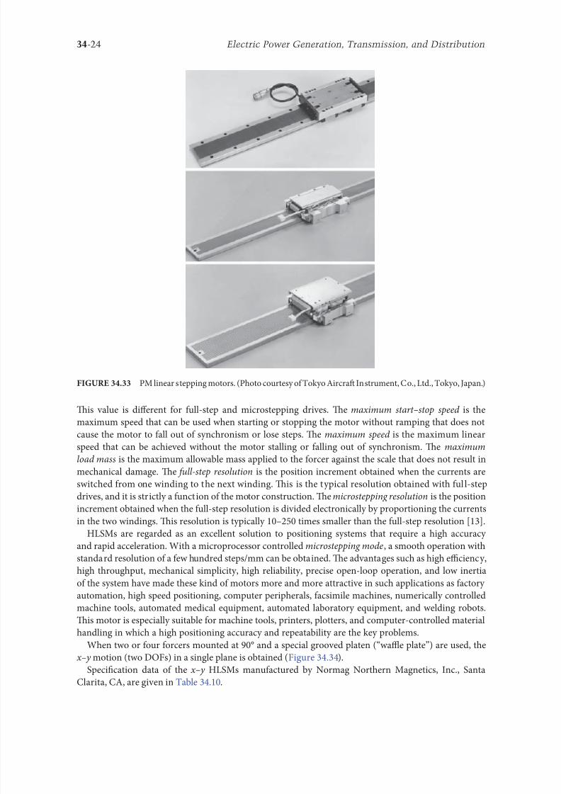
8102019 Power Handbook
httpslidepdfcomreaderfullpower-handbook 3943
34-24 Electric Power Generation Transmission and Distribution
Tis value is different or ull-step and microstepping drives Te maximum startndashstop speed is the
maximum speed that can be used when starting or stopping the motor without ramping that does not
cause the motor to all out o synchronism or lose steps Te maximum speed is the maximum linear
speed that can be achieved without the motor stalling or alling out o synchronism Te maximum
load mass is the maximum allowable mass applied to the orcer against the scale that does not result in
mechanical damage Te ull-step resolution is the position increment obtained when the currents are
switched rom one winding to the next winding Tis is the typical resolution obtained with ul l-step
drives and it is strictly a unction o the motor construction Te microstepping resolution is the position
increment obtained when the ull-step resolution is divided electronically by proportioning the currents
in the two windings Tis resolution is typically 10ndash250 times smaller than the ull-step resolution [13]
HLSMs are regarded as an excellent solution to positioning systems that require a high accuracy
and rapid acceleration With a microprocessor controlled microstepping mode a smooth operation with
standard resolution o a ew hundred stepsmm can be obtained Te advantages such as high efficiencyhigh throughput mechanical simplicity high reliability precise open-loop operation and low inertia
o the system have made these kind o motors more and more attractive in such applications as actory
automation high speed positioning computer peripherals acsimile machines numerically controlled
machine tools automated medical equipment automated laboratory equipment and welding robots
Tis motor is especially suitable or machine tools printers plotters and computer-controlled material
handling in which a high positioning accuracy and repeatability are the key problems
When two or our orcers mounted at 90deg and a special grooved platen (ldquowaffle platerdquo) are used the
xndashy motion (two DOFs) in a single plane is obtained (Figure 3434)
Speci1047297cation data o the xndashy HLSMs manuactured by Normag Northern Magnetics Inc Santa
Clarita CA are given in able 3410
PM linear stepping motors (Photo courtesy o okyo Aircraf Instrument Co Ltd okyo Japan)
8102019 Power Handbook
httpslidepdfcomreaderfullpower-handbook 4043
34-25Linear Electric Motors
345 Switched Reluctance Motors
Te topology o a linear switched reluctance motor is similar to that o a stepping motor with variable
reluctance platen In addition it is equipped with position sensors Te turn-on and turn-off instant o
the input current is synchronized with the position o the moving part Te thrust is very sensitive to
the turn-on and turn-off instant
In the case o a linear stepping or linear switched reluctance motor the speed v o the moving part is
v v s sw= = τ
(348)
where
sw is the undamental switching requency in one armature phase winding
τ is the pole pitch o the reaction rail
For a rotary stepping or switched reluctance motor sw = 2 pr n where 2 pr is the number o rotor poles and
n is rotational speed in revs
A linear switched reluctance motor has a doubly salient magnetic circuit with a polyphase winding
on the armature Longitudinal and transverse 1047298ux designs are shown in Figure 3435 A linear switched
reluctance motor allows precise speed and position-controlled linear motion at low speeds and is not sub-
ject to design constraints (minimum speed limited by minimum easible pole pitch) o linear AC motors
x
y
12
3
4
1
1
2
2
HLSM with a our-unit orcer to obtain the xndashy motion 1 orcers or the x -direction 2 orcers
or the y -direction 3 platen 4 air pressure
Data o xndashy HLSMs Manuactured by Normag Northern Magnetics Inc
Santa Clarita CA
Parameter 4XY0602-2-0 4XY2002-2-0 4XY2004-2-0 4XY2504-2-0
Number o orcer units per axis 1 1 2 2
Number o phases 2 2 2(4) 2(4)Static thrust N 133 400 980 1330
Trust at 1 ms N 111 311 712 980
Normal attractive orce N 1600 4000 14400 18000
Resistance per phase Ω 29 33 16 19
Inductance per phase mH 15 40 20 23
Input phase current A 20 20 40 40
Air gap mm 002
Maximum temperature degC 110
Mass kg 32 072 20 15
Repeatability mm 000254
Resolution mm 000254
Bearing type Air
8102019 Power Handbook
httpslidepdfcomreaderfullpower-handbook 4143
34-26 Electric Power Generation Transmission and Distribution
346 Linear Positioning Stages
Linear motors are now playing a key role in advanced precision linear positioning Linear precision posi-
tioning systems can be classi1047297ed into open-loop systems with HLSMs and closed-loop servo systems
with LSMs LBMs or LIMs
A PM LSMndashdriven positioning stage is shown in Figure 3436 A stationary base is made o Al steel
ceramic or granite plate It provides a stable precise and 1047298at platorm to which all stationary position-
ing components are attached Te base o the stage is attached to the host system with the aid o mount-
ing screws
Te moving table accommodates all moving positioning components o achieve maximum accelera-
tion the mass o the moving table should be as small as possible and usually Al is used as a lightweight
material A number o mounting holes on the moving table is necessary to 1047297x the payload to the mount-
ing table
Linear bearing rails provide a precise guidance to the moving table A minimum o one bearing rail
is required Linear ball bearing or air bearings are attached to each rail
Te armature o a linear motor is astened to the moving table and reaction rail (PM excitation sys-tem) is built in the base between the rails (Figure 3436)
A linear encoder is needed to obtain precise control o position o the table velocity and acceleration
Te read head o the encoder is attached to the moving table
(a) (b)
3
3
221
1
Linear switched reluctance motor con1047297gurations (a) longitudinal 1047298ux design and (b) transverse
1047298ux design 1 armature winding 2 armature stack 3 platen
12
3
5
4
7
6
8
Linear positioning stage driven by PM LBM 1 base 2 moving table 3 armature o LBM 4 PMs
5 linear bearing 6 encoder 7 cable carrier 8 limit switch (Courtesy o Normag Santa Clarita CA)
8102019 Power Handbook
httpslidepdfcomreaderfullpower-handbook 4243
34-27Linear Electric Motors
Noncontact limit switches ixed to the base provide an overtravel protection and init ial homing
A cable carrier accommodates and routes electrical cables between the moving table and stationary
connector box 1047297xed to the base
An HLSM-driven linear precision stage is o similar construction Instead o PMs between bearing
rails it has a variable reluctance platen HLSMs usually need air bearings and in addition to the electri-
cal cables an air hose between air bearings and the compressor is requiredLinear positioning stages are used in semiconductor technology electronic assembly quality assur-
ance laser cutting optical scanning water jet cutting gantry systems (x y z stages) color printers
plotters and Cartesian coordinate robotics
References
1 Anorad Linear Motors Inormation Brochure Anorad Hauppauge New York 2007 wwwanoradcom
2 Boldea I and Nasar SA Linear Motion Electromagnetic Systems John Wiley amp Sons New York 1985
3 Boldea I and Nasar SA Linear Electric Actuators and Generators Cambridge University Press
New York 2005
4 Compumotor Digiplan Positioning Control Systems and Drives Parker Hanni1047297n CorporationRohnert Park CA 2011
5 Everes W Henneberger G Wunderlich H and Selig A A linear homopolar motor or a trans-
portation system 2nd International Symposium on Linear Drives or Industry Applications (LDIArsquo98)
okyo Japan 1998 pp 46ndash49
6 Gieras JF Linear Induction Drives Clarendon Press Oxord UK 1994
7 Gieras JF Status o linear motors in the United States International Symposium on Linear Drives
or Industry Applications (LDIArsquo03) Birmingham UK 2003 pp 169ndash176
8 Gieras JF Gientkowski Z Mews J and Splawski P Analytical calculation o electrodynamic
levitation orces in a special-purpose linear induction motor International Electric Machines and
Drives Conerence (IEMDCrsquo11) Niagara Falls Ontario Canada 2011 [on CD-ROM]
9 Gieras JF Piech ZJ and omczuk BZ Linear Synchronous Motors ransportation and Automation Systems aylor amp Francis (CRC Press) Boca Raton FL 2011
10 Hoang E Ahmed AHB and Lucidarme J Switching 1047298ux permanent magnet polyphase syn-
chronous machines 7th European Conerence on Power Electronics and Applications (EPErsquo97)
Vol 3 rondheim Norway 1977 pp 903ndash908
11 Kollmorgen Linear Motors Aim to Cut Cost o Semiconductors and Electronics Manuacture
Kollmorgen Radord VA 1997
12 Laithwaite ER A History o Linear Electric Motors Macmillan London UK 1987
13 Linear Step Motor Inormation Brochure okyo Aircraf Instrument Co Ltd okyo Japan
1998
14 LinMot Design Manual Sulzer Electronics Ltd Zuumlrich Switzerland 1999
15 Locci N and Marongiu I Modelling and testing a new linear reluctance motor InternationalConerence on Electrical Machines (ICEMrsquo92) Vol 2 Manchester UK 1992 pp 706ndash710
16 Rauch SE and Johnson LJ Design principles o 1047298ux-switch alternators AIEE rans Part III
74(12) 1261ndash1269 1955
17 Rosenmayr M Casat Glavitsch A and Stemmler H SwissmetromdashPower supply or a high-
power-propulsion system with short stator linear motors 15th International Conerence on
Magnetically Levitated Systems and Linear Drives Maglevrsquo98 Mount Fuji Yamanashi Japan 1998
pp 280ndash286
18 Sanada M Morimoto S and akeda Y Reluctance equalization design o multi 1047298ux barrier con-
struction or linear synchronous reluctance motors 2nd International Symposium on Linear Drives
or Industrial Applications (LDIArsquo98) okyo Japan 1998 pp 259ndash262
8102019 Power Handbook
httpslidepdfcomreaderfullpower-handbook 4343
34-28 Electric Power Generation Transmission and Distribution
19 Seok-Myeong J and Sang-Sub J Design and analysis o the linear homopolar synchronous motor
or integrated magnetic propulsion and suspension 2nd International Symposium on Linear Drives
or Industrial Applications (LDIArsquo98) okyo Japan 1998 pp 74ndash77
20 Synchronous Linear Motor 1FN6 Te Electrical Gear Rack Siemens AG Industry Sector Drive
echnologies Motion Control Erlangen Germany 2008
21 Yamada H Handbook o Linear Motor Applications (in Japanese) Kogyo Chosaki Publishing Cookyo Japan 1986
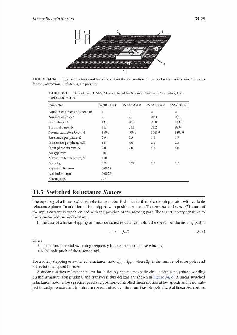
8102019 Power Handbook
httpslidepdfcomreaderfullpower-handbook 4043
34-25Linear Electric Motors
345 Switched Reluctance Motors
Te topology o a linear switched reluctance motor is similar to that o a stepping motor with variable
reluctance platen In addition it is equipped with position sensors Te turn-on and turn-off instant o
the input current is synchronized with the position o the moving part Te thrust is very sensitive to
the turn-on and turn-off instant
In the case o a linear stepping or linear switched reluctance motor the speed v o the moving part is
v v s sw= = τ
(348)
where
sw is the undamental switching requency in one armature phase winding
τ is the pole pitch o the reaction rail
For a rotary stepping or switched reluctance motor sw = 2 pr n where 2 pr is the number o rotor poles and
n is rotational speed in revs
A linear switched reluctance motor has a doubly salient magnetic circuit with a polyphase winding
on the armature Longitudinal and transverse 1047298ux designs are shown in Figure 3435 A linear switched
reluctance motor allows precise speed and position-controlled linear motion at low speeds and is not sub-
ject to design constraints (minimum speed limited by minimum easible pole pitch) o linear AC motors
x
y
12
3
4
1
1
2
2
HLSM with a our-unit orcer to obtain the xndashy motion 1 orcers or the x -direction 2 orcers
or the y -direction 3 platen 4 air pressure
Data o xndashy HLSMs Manuactured by Normag Northern Magnetics Inc
Santa Clarita CA
Parameter 4XY0602-2-0 4XY2002-2-0 4XY2004-2-0 4XY2504-2-0
Number o orcer units per axis 1 1 2 2
Number o phases 2 2 2(4) 2(4)Static thrust N 133 400 980 1330
Trust at 1 ms N 111 311 712 980
Normal attractive orce N 1600 4000 14400 18000
Resistance per phase Ω 29 33 16 19
Inductance per phase mH 15 40 20 23
Input phase current A 20 20 40 40
Air gap mm 002
Maximum temperature degC 110
Mass kg 32 072 20 15
Repeatability mm 000254
Resolution mm 000254
Bearing type Air
8102019 Power Handbook
httpslidepdfcomreaderfullpower-handbook 4143
34-26 Electric Power Generation Transmission and Distribution
346 Linear Positioning Stages
Linear motors are now playing a key role in advanced precision linear positioning Linear precision posi-
tioning systems can be classi1047297ed into open-loop systems with HLSMs and closed-loop servo systems
with LSMs LBMs or LIMs
A PM LSMndashdriven positioning stage is shown in Figure 3436 A stationary base is made o Al steel
ceramic or granite plate It provides a stable precise and 1047298at platorm to which all stationary position-
ing components are attached Te base o the stage is attached to the host system with the aid o mount-
ing screws
Te moving table accommodates all moving positioning components o achieve maximum accelera-
tion the mass o the moving table should be as small as possible and usually Al is used as a lightweight
material A number o mounting holes on the moving table is necessary to 1047297x the payload to the mount-
ing table
Linear bearing rails provide a precise guidance to the moving table A minimum o one bearing rail
is required Linear ball bearing or air bearings are attached to each rail
Te armature o a linear motor is astened to the moving table and reaction rail (PM excitation sys-tem) is built in the base between the rails (Figure 3436)
A linear encoder is needed to obtain precise control o position o the table velocity and acceleration
Te read head o the encoder is attached to the moving table
(a) (b)
3
3
221
1
Linear switched reluctance motor con1047297gurations (a) longitudinal 1047298ux design and (b) transverse
1047298ux design 1 armature winding 2 armature stack 3 platen
12
3
5
4
7
6
8
Linear positioning stage driven by PM LBM 1 base 2 moving table 3 armature o LBM 4 PMs
5 linear bearing 6 encoder 7 cable carrier 8 limit switch (Courtesy o Normag Santa Clarita CA)
8102019 Power Handbook
httpslidepdfcomreaderfullpower-handbook 4243
34-27Linear Electric Motors
Noncontact limit switches ixed to the base provide an overtravel protection and init ial homing
A cable carrier accommodates and routes electrical cables between the moving table and stationary
connector box 1047297xed to the base
An HLSM-driven linear precision stage is o similar construction Instead o PMs between bearing
rails it has a variable reluctance platen HLSMs usually need air bearings and in addition to the electri-
cal cables an air hose between air bearings and the compressor is requiredLinear positioning stages are used in semiconductor technology electronic assembly quality assur-
ance laser cutting optical scanning water jet cutting gantry systems (x y z stages) color printers
plotters and Cartesian coordinate robotics
References
1 Anorad Linear Motors Inormation Brochure Anorad Hauppauge New York 2007 wwwanoradcom
2 Boldea I and Nasar SA Linear Motion Electromagnetic Systems John Wiley amp Sons New York 1985
3 Boldea I and Nasar SA Linear Electric Actuators and Generators Cambridge University Press
New York 2005
4 Compumotor Digiplan Positioning Control Systems and Drives Parker Hanni1047297n CorporationRohnert Park CA 2011
5 Everes W Henneberger G Wunderlich H and Selig A A linear homopolar motor or a trans-
portation system 2nd International Symposium on Linear Drives or Industry Applications (LDIArsquo98)
okyo Japan 1998 pp 46ndash49
6 Gieras JF Linear Induction Drives Clarendon Press Oxord UK 1994
7 Gieras JF Status o linear motors in the United States International Symposium on Linear Drives
or Industry Applications (LDIArsquo03) Birmingham UK 2003 pp 169ndash176
8 Gieras JF Gientkowski Z Mews J and Splawski P Analytical calculation o electrodynamic
levitation orces in a special-purpose linear induction motor International Electric Machines and
Drives Conerence (IEMDCrsquo11) Niagara Falls Ontario Canada 2011 [on CD-ROM]
9 Gieras JF Piech ZJ and omczuk BZ Linear Synchronous Motors ransportation and Automation Systems aylor amp Francis (CRC Press) Boca Raton FL 2011
10 Hoang E Ahmed AHB and Lucidarme J Switching 1047298ux permanent magnet polyphase syn-
chronous machines 7th European Conerence on Power Electronics and Applications (EPErsquo97)
Vol 3 rondheim Norway 1977 pp 903ndash908
11 Kollmorgen Linear Motors Aim to Cut Cost o Semiconductors and Electronics Manuacture
Kollmorgen Radord VA 1997
12 Laithwaite ER A History o Linear Electric Motors Macmillan London UK 1987
13 Linear Step Motor Inormation Brochure okyo Aircraf Instrument Co Ltd okyo Japan
1998
14 LinMot Design Manual Sulzer Electronics Ltd Zuumlrich Switzerland 1999
15 Locci N and Marongiu I Modelling and testing a new linear reluctance motor InternationalConerence on Electrical Machines (ICEMrsquo92) Vol 2 Manchester UK 1992 pp 706ndash710
16 Rauch SE and Johnson LJ Design principles o 1047298ux-switch alternators AIEE rans Part III
74(12) 1261ndash1269 1955
17 Rosenmayr M Casat Glavitsch A and Stemmler H SwissmetromdashPower supply or a high-
power-propulsion system with short stator linear motors 15th International Conerence on
Magnetically Levitated Systems and Linear Drives Maglevrsquo98 Mount Fuji Yamanashi Japan 1998
pp 280ndash286
18 Sanada M Morimoto S and akeda Y Reluctance equalization design o multi 1047298ux barrier con-
struction or linear synchronous reluctance motors 2nd International Symposium on Linear Drives
or Industrial Applications (LDIArsquo98) okyo Japan 1998 pp 259ndash262
8102019 Power Handbook
httpslidepdfcomreaderfullpower-handbook 4343
34-28 Electric Power Generation Transmission and Distribution
19 Seok-Myeong J and Sang-Sub J Design and analysis o the linear homopolar synchronous motor
or integrated magnetic propulsion and suspension 2nd International Symposium on Linear Drives
or Industrial Applications (LDIArsquo98) okyo Japan 1998 pp 74ndash77
20 Synchronous Linear Motor 1FN6 Te Electrical Gear Rack Siemens AG Industry Sector Drive
echnologies Motion Control Erlangen Germany 2008
21 Yamada H Handbook o Linear Motor Applications (in Japanese) Kogyo Chosaki Publishing Cookyo Japan 1986
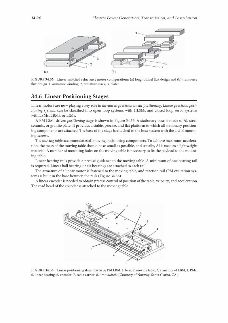
8102019 Power Handbook
httpslidepdfcomreaderfullpower-handbook 4143
34-26 Electric Power Generation Transmission and Distribution
346 Linear Positioning Stages
Linear motors are now playing a key role in advanced precision linear positioning Linear precision posi-
tioning systems can be classi1047297ed into open-loop systems with HLSMs and closed-loop servo systems
with LSMs LBMs or LIMs
A PM LSMndashdriven positioning stage is shown in Figure 3436 A stationary base is made o Al steel
ceramic or granite plate It provides a stable precise and 1047298at platorm to which all stationary position-
ing components are attached Te base o the stage is attached to the host system with the aid o mount-
ing screws
Te moving table accommodates all moving positioning components o achieve maximum accelera-
tion the mass o the moving table should be as small as possible and usually Al is used as a lightweight
material A number o mounting holes on the moving table is necessary to 1047297x the payload to the mount-
ing table
Linear bearing rails provide a precise guidance to the moving table A minimum o one bearing rail
is required Linear ball bearing or air bearings are attached to each rail
Te armature o a linear motor is astened to the moving table and reaction rail (PM excitation sys-tem) is built in the base between the rails (Figure 3436)
A linear encoder is needed to obtain precise control o position o the table velocity and acceleration
Te read head o the encoder is attached to the moving table
(a) (b)
3
3
221
1
Linear switched reluctance motor con1047297gurations (a) longitudinal 1047298ux design and (b) transverse
1047298ux design 1 armature winding 2 armature stack 3 platen
12
3
5
4
7
6
8
Linear positioning stage driven by PM LBM 1 base 2 moving table 3 armature o LBM 4 PMs
5 linear bearing 6 encoder 7 cable carrier 8 limit switch (Courtesy o Normag Santa Clarita CA)
8102019 Power Handbook
httpslidepdfcomreaderfullpower-handbook 4243
34-27Linear Electric Motors
Noncontact limit switches ixed to the base provide an overtravel protection and init ial homing
A cable carrier accommodates and routes electrical cables between the moving table and stationary
connector box 1047297xed to the base
An HLSM-driven linear precision stage is o similar construction Instead o PMs between bearing
rails it has a variable reluctance platen HLSMs usually need air bearings and in addition to the electri-
cal cables an air hose between air bearings and the compressor is requiredLinear positioning stages are used in semiconductor technology electronic assembly quality assur-
ance laser cutting optical scanning water jet cutting gantry systems (x y z stages) color printers
plotters and Cartesian coordinate robotics
References
1 Anorad Linear Motors Inormation Brochure Anorad Hauppauge New York 2007 wwwanoradcom
2 Boldea I and Nasar SA Linear Motion Electromagnetic Systems John Wiley amp Sons New York 1985
3 Boldea I and Nasar SA Linear Electric Actuators and Generators Cambridge University Press
New York 2005
4 Compumotor Digiplan Positioning Control Systems and Drives Parker Hanni1047297n CorporationRohnert Park CA 2011
5 Everes W Henneberger G Wunderlich H and Selig A A linear homopolar motor or a trans-
portation system 2nd International Symposium on Linear Drives or Industry Applications (LDIArsquo98)
okyo Japan 1998 pp 46ndash49
6 Gieras JF Linear Induction Drives Clarendon Press Oxord UK 1994
7 Gieras JF Status o linear motors in the United States International Symposium on Linear Drives
or Industry Applications (LDIArsquo03) Birmingham UK 2003 pp 169ndash176
8 Gieras JF Gientkowski Z Mews J and Splawski P Analytical calculation o electrodynamic
levitation orces in a special-purpose linear induction motor International Electric Machines and
Drives Conerence (IEMDCrsquo11) Niagara Falls Ontario Canada 2011 [on CD-ROM]
9 Gieras JF Piech ZJ and omczuk BZ Linear Synchronous Motors ransportation and Automation Systems aylor amp Francis (CRC Press) Boca Raton FL 2011
10 Hoang E Ahmed AHB and Lucidarme J Switching 1047298ux permanent magnet polyphase syn-
chronous machines 7th European Conerence on Power Electronics and Applications (EPErsquo97)
Vol 3 rondheim Norway 1977 pp 903ndash908
11 Kollmorgen Linear Motors Aim to Cut Cost o Semiconductors and Electronics Manuacture
Kollmorgen Radord VA 1997
12 Laithwaite ER A History o Linear Electric Motors Macmillan London UK 1987
13 Linear Step Motor Inormation Brochure okyo Aircraf Instrument Co Ltd okyo Japan
1998
14 LinMot Design Manual Sulzer Electronics Ltd Zuumlrich Switzerland 1999
15 Locci N and Marongiu I Modelling and testing a new linear reluctance motor InternationalConerence on Electrical Machines (ICEMrsquo92) Vol 2 Manchester UK 1992 pp 706ndash710
16 Rauch SE and Johnson LJ Design principles o 1047298ux-switch alternators AIEE rans Part III
74(12) 1261ndash1269 1955
17 Rosenmayr M Casat Glavitsch A and Stemmler H SwissmetromdashPower supply or a high-
power-propulsion system with short stator linear motors 15th International Conerence on
Magnetically Levitated Systems and Linear Drives Maglevrsquo98 Mount Fuji Yamanashi Japan 1998
pp 280ndash286
18 Sanada M Morimoto S and akeda Y Reluctance equalization design o multi 1047298ux barrier con-
struction or linear synchronous reluctance motors 2nd International Symposium on Linear Drives
or Industrial Applications (LDIArsquo98) okyo Japan 1998 pp 259ndash262
8102019 Power Handbook
httpslidepdfcomreaderfullpower-handbook 4343
34-28 Electric Power Generation Transmission and Distribution
19 Seok-Myeong J and Sang-Sub J Design and analysis o the linear homopolar synchronous motor
or integrated magnetic propulsion and suspension 2nd International Symposium on Linear Drives
or Industrial Applications (LDIArsquo98) okyo Japan 1998 pp 74ndash77
20 Synchronous Linear Motor 1FN6 Te Electrical Gear Rack Siemens AG Industry Sector Drive
echnologies Motion Control Erlangen Germany 2008
21 Yamada H Handbook o Linear Motor Applications (in Japanese) Kogyo Chosaki Publishing Cookyo Japan 1986
8102019 Power Handbook
httpslidepdfcomreaderfullpower-handbook 4243
34-27Linear Electric Motors
Noncontact limit switches ixed to the base provide an overtravel protection and init ial homing
A cable carrier accommodates and routes electrical cables between the moving table and stationary
connector box 1047297xed to the base
An HLSM-driven linear precision stage is o similar construction Instead o PMs between bearing
rails it has a variable reluctance platen HLSMs usually need air bearings and in addition to the electri-
cal cables an air hose between air bearings and the compressor is requiredLinear positioning stages are used in semiconductor technology electronic assembly quality assur-
ance laser cutting optical scanning water jet cutting gantry systems (x y z stages) color printers
plotters and Cartesian coordinate robotics
References
1 Anorad Linear Motors Inormation Brochure Anorad Hauppauge New York 2007 wwwanoradcom
2 Boldea I and Nasar SA Linear Motion Electromagnetic Systems John Wiley amp Sons New York 1985
3 Boldea I and Nasar SA Linear Electric Actuators and Generators Cambridge University Press
New York 2005
4 Compumotor Digiplan Positioning Control Systems and Drives Parker Hanni1047297n CorporationRohnert Park CA 2011
5 Everes W Henneberger G Wunderlich H and Selig A A linear homopolar motor or a trans-
portation system 2nd International Symposium on Linear Drives or Industry Applications (LDIArsquo98)
okyo Japan 1998 pp 46ndash49
6 Gieras JF Linear Induction Drives Clarendon Press Oxord UK 1994
7 Gieras JF Status o linear motors in the United States International Symposium on Linear Drives
or Industry Applications (LDIArsquo03) Birmingham UK 2003 pp 169ndash176
8 Gieras JF Gientkowski Z Mews J and Splawski P Analytical calculation o electrodynamic
levitation orces in a special-purpose linear induction motor International Electric Machines and
Drives Conerence (IEMDCrsquo11) Niagara Falls Ontario Canada 2011 [on CD-ROM]
9 Gieras JF Piech ZJ and omczuk BZ Linear Synchronous Motors ransportation and Automation Systems aylor amp Francis (CRC Press) Boca Raton FL 2011
10 Hoang E Ahmed AHB and Lucidarme J Switching 1047298ux permanent magnet polyphase syn-
chronous machines 7th European Conerence on Power Electronics and Applications (EPErsquo97)
Vol 3 rondheim Norway 1977 pp 903ndash908
11 Kollmorgen Linear Motors Aim to Cut Cost o Semiconductors and Electronics Manuacture
Kollmorgen Radord VA 1997
12 Laithwaite ER A History o Linear Electric Motors Macmillan London UK 1987
13 Linear Step Motor Inormation Brochure okyo Aircraf Instrument Co Ltd okyo Japan
1998
14 LinMot Design Manual Sulzer Electronics Ltd Zuumlrich Switzerland 1999
15 Locci N and Marongiu I Modelling and testing a new linear reluctance motor InternationalConerence on Electrical Machines (ICEMrsquo92) Vol 2 Manchester UK 1992 pp 706ndash710
16 Rauch SE and Johnson LJ Design principles o 1047298ux-switch alternators AIEE rans Part III
74(12) 1261ndash1269 1955
17 Rosenmayr M Casat Glavitsch A and Stemmler H SwissmetromdashPower supply or a high-
power-propulsion system with short stator linear motors 15th International Conerence on
Magnetically Levitated Systems and Linear Drives Maglevrsquo98 Mount Fuji Yamanashi Japan 1998
pp 280ndash286
18 Sanada M Morimoto S and akeda Y Reluctance equalization design o multi 1047298ux barrier con-
struction or linear synchronous reluctance motors 2nd International Symposium on Linear Drives
or Industrial Applications (LDIArsquo98) okyo Japan 1998 pp 259ndash262
8102019 Power Handbook
httpslidepdfcomreaderfullpower-handbook 4343
34-28 Electric Power Generation Transmission and Distribution
19 Seok-Myeong J and Sang-Sub J Design and analysis o the linear homopolar synchronous motor
or integrated magnetic propulsion and suspension 2nd International Symposium on Linear Drives
or Industrial Applications (LDIArsquo98) okyo Japan 1998 pp 74ndash77
20 Synchronous Linear Motor 1FN6 Te Electrical Gear Rack Siemens AG Industry Sector Drive
echnologies Motion Control Erlangen Germany 2008
21 Yamada H Handbook o Linear Motor Applications (in Japanese) Kogyo Chosaki Publishing Cookyo Japan 1986