Embed Size (px)
Citation preview
International Research Journal of Engineering and Technology (IRJET) e-ISSN: 2395 -0056
Volume: 03 Issue: 01 | Jan -2016 www.irjet.net p-ISSN: 2395-0072
© 2016, IRJET | Impact Factor value: 5.181 | ISO 9001:2008 Certified Journal | Page 1333
POWER GENERATION USING RUMBLERS
Santosh Gandhamwar1, Sufia Sukhyani2, Saurabh Ukkali3, Vikrant Verukhia4
Mechanical Engineering Department,
Smt. Kashibai Navale College of Engineering, Pune, MS
Prof. Swapnil U. Deokar1.
Mechanical Engineering Department,
Smt. Kashibai Navale College of Engineering, Pune, MS
--------------------------------------------------------------------------------------------------------------------
ABSTRACT: Man has been using energy on this earth since its existence. This energy has been used in various forms until today. As known to all, energy can neither be created nor be eliminated. Processes that take place in the nature around us involve the conversion of energy from one form to another. The formation of clouds, the blowing of the wind and the flowing of water all stand testimony to this fact. The radical usage of these forms of energy has resulted in a crisis we face today. In order to stand up to this crisis, development of methods of optimal utilization is necessary. Development will not only help us be at ease but will also help in preserving the wonderful environment that has been serving us for years. The best method for development is using the nature’s rule of conversion of energy. It is the cheapest new source of energy available.
This project aims in showing the ease of tapping energy and using it from a simple common system used all over the world that is the speed rumble mechanism. Generation of energy from the speed rumble mechanism is a most recent power generation concept which can be utilized all around the world. In this concept, the kinetic energy of the vehicles is converted into electric energy by using the speed rumble mechanism which is to be installed on the roads. The mechanism takes the stroke motion of the cars as input energy, converts this energy to rotary motion with the help of the rack and pinion mechanism and generates electricity. This project also explains the working principle of the designed mechanism, its practical implementations and its advantages.
The utilization of energy is an indication of the development and growth of a nation and mankind. One might conclude that in order to be materially rich and prosperous, one must consume more and more energy. Well then this project is a best source of energy we can get in our day to day lives.
Key words: Rack and pinion, speed rumble mechanism, energy conversion
1. INTRODUCTION: Increase in the demand of energy has necessitated the identification of non-conventional resources of energy. An
energy crisis leads to a price rise in the supply of energy resources in the economy. This makes it more difficult to discover various other sources with limited requirements. Thus, the well developed countries are at a safer stage when it comes to crisis whereas it becomes more difficult for the developing countries to cope to the changes of price in the economy. Along developing countries. This lag results in the striving of the developing countries to face crisis. Over this vast development, there have also been various techniques which have led to power generation at an affordable price. Out of these cost friendly techniques is the power generation by a speed rumble mechanism. In this mechanism, the kinetic energy is tapped and converted into electric energy with the help of the rack and pinion mechanism. The main motto of this paper is to explain the generation of power from speed breaker (rumble) and the possible speed rumble mechanism required.
International Research Journal of Engineering and Technology (IRJET) e-ISSN: 2395 -0056
Volume: 03 Issue: 01 | Jan -2016 www.irjet.net p-ISSN: 2395-0072
© 2016, IRJET | Impact Factor value: 5.181 | ISO 9001:2008 Certified Journal | Page 1334
1.2. Objectives:
The primary objective of the system is Generate energy from rumblers.
This system has three major objectives:
To use Kinetic Energy which is normally wasted To give Passenger Comfort To generate electricity.
1.3 Problem Statement:
To generate electricity by the utilization of the energy produced in vehicles which are wasted on speed breakers at an affordable cost with a universally used mechanism.
2. LITERATURE REVIEW:
1. “Road Power Generation by Speed Breaker” by Ch.Bhanu Prakash, A.V.Ramana Rao, P.Srinuvas
Energy is one of the basic quantitative properties describing a physical system or object's state. Energy can be transformed among a number of forms that may each manifest and be measurable in differing ways. The total energy of a system can be calculated by simple addition when it is composed of multiple non-interacting parts or has multiple distinct forms of energy. Common energy forms include the kinetic energy of a moving object. In the earlier attempt we required suspension system for links getting back to the original position here the other joint does the return stroke steadily thus overcoming the limitations of the suspension effect . In this present paper an attempt has been made to tap the energy and generate the power by the road power generating system. This is done by introducing the powered bearing which rotates the shaft in one direction and moves freely over rollers in other direction. The return stroke is operated by the other joint, where as earlier the same return stroke was operated by the suspension system. The powered bearing is similar to the small toothed wheel in the rear tires of the normal bicycles, when the vehicle wheel passes over the third joint the first joint returns to the original position. Similarly when a vehicle passes over the first joint, the third join returns to the original position. By introducing this mechanism, we could operate 12 volts DC Motor at 30 RPM generating 70 watts electric power.
2. “Development Of Mechanism For Recovery Of Energy Of Suspension System.” By Mr. Swapnil Kamthe, Mr. Rahul Kadam, Mr. Aniket Dhore, Mr. Shivkumar Falmari, Prof. Subhash Ghadve, Prof. Mukesh Chaudhari
This project is divided in two systems. First is Air-conditioning working and second is Electricity generation. Vehicle air-conditioning can significantly impact fuel economy and tailpipe emissions of conventional and hybrid electric vehicles (HEV) and reduce electric vehicle (EV) range. There is lot of fuel burn only for working of A.C. while driving the car. If A.C. will run on other system rather than fuel then there will lot of fuel save in car. Efficiency of car will also increase. In industries as well as in our economic life in general significance of compressor shows a steadily increase productivity in most important industrial fields such as mining, metallurgical, civil engineering, architecture and in all types of machine construction etc. This is specially planned to design and fabricate the conversion unit for utilizing the available unconventional energy source. That is available energy in low intensity with ample quantity can be utilized. This machine converts linear motion in to rotary motion. The rotational power generates electricity.
3. “A Review on Energy-Regenerative Suspension Systems for Vehicles” by Zhang Jin-qiu, Peng Zhi-zhao*, Zhang Lei, Zhang Yu
The conventional vehicle suspension dissipates the mechanical vibration energy in the form of heat which waste considerable energy. The regenerative suspensions have attracted much attention in recent years for the improvement of vibration attenuating performance as well as the reduction of energy dissipation. Above all, the amount of energy dissipation and the potential of energy regeneration are discussed, then the research and development of regenerative suspension is reviewed,
International Research Journal of Engineering and Technology (IRJET) e-ISSN: 2395 -0056
Volume: 03 Issue: 01 | Jan -2016 www.irjet.net p-ISSN: 2395-0072
© 2016, IRJET | Impact Factor value: 5.181 | ISO 9001:2008 Certified Journal | Page 1335
and the energy harvesting schemes and their characteristics are summarized and remarked. In conclusion, only combining vibration reducing performance and energy harvesting efficiency can the regenerative suspensions have a promising prospect.
3.1. Steps
Designing of the model Selection of components Manufacturing of parts Assembly
3.2. Specifications
Sr. No. Description Material
1. Rumblers Mild Steel 2. Springs Mild Steel 3. Rack and Pinion Mild Steel 4. Shaft Mild Steel 5. Universal Coupling
(spiral bevel gears) Mild Steel
6. Bearing Standard Material(6000) 7. Belt Drive Rubber 8. Pulley Mild Steel
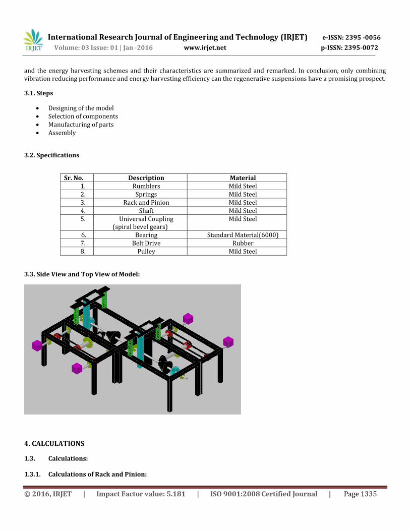
3.3. Side View and Top View of Model:
4. CALCULATIONS
1.3. Calculations:
1.3.1. Calculations of Rack and Pinion:
International Research Journal of Engineering and Technology (IRJET) e-ISSN: 2395 -0056
Volume: 03 Issue: 01 | Jan -2016 www.irjet.net p-ISSN: 2395-0072
© 2016, IRJET | Impact Factor value: 5.181 | ISO 9001:2008 Certified Journal | Page 1336
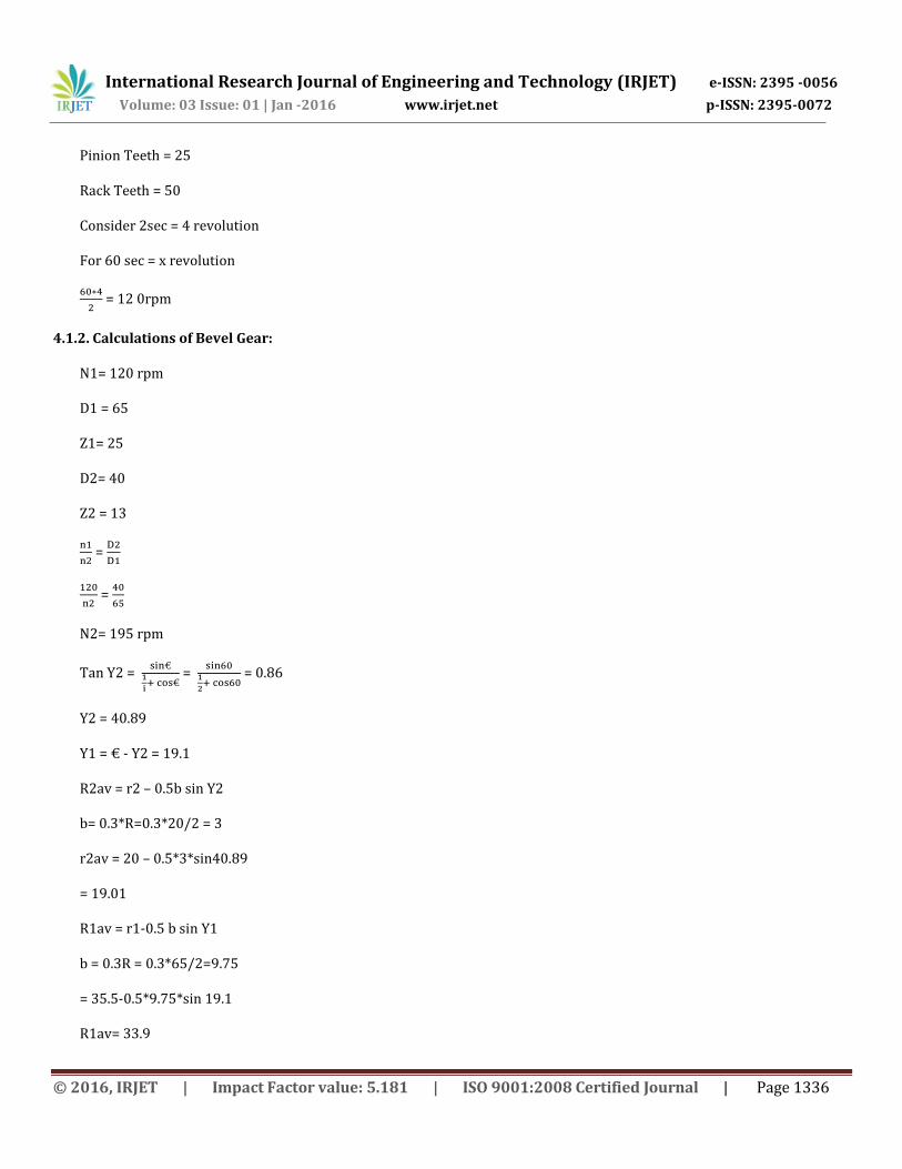
Pinion Teeth = 25
Rack Teeth = 50
Consider 2sec = 4 revolution
For 60 sec = x revolution
= 12 0rpm
4.1.2. Calculations of Bevel Gear:
N1= 120 rpm
D1 = 65
Z1= 25
D2= 40
Z2 = 13
=
=
N2= 195 rpm
Tan Y2 =
=
= 0.86
Y2 = 40.89
Y1 = € - Y2 = 19.1
R2av = r2 – 0.5b sin Y2
b= 0.3*R=0.3*20/2 = 3
r2av = 20 – 0.5*3*sin40.89
= 19.01
R1av = r1-0.5 b sin Y1
b = 0.3R = 0.3*65/2=9.75
= 35.5-0.5*9.75*sin 19.1
R1av= 33.9
International Research Journal of Engineering and Technology (IRJET) e-ISSN: 2395 -0056
Volume: 03 Issue: 01 | Jan -2016 www.irjet.net p-ISSN: 2395-0072
© 2016, IRJET | Impact Factor value: 5.181 | ISO 9001:2008 Certified Journal | Page 1337
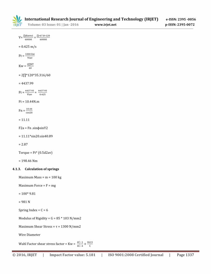
V=
=
= 0.425 m/s
Ft =
Kw =
= 2∏*120*35.316/60
= 4437.99
Ft =
=
Ft = 10.44N.m
Fn =
= 11.11
F2a = Fn .sinɸsinY2
= 11.11*sin20.sin40.89
= 2.87
Torque = Ft* (0.5d2av)
= 198.46 Nm
4.1.3. Calculation of springs
Maximum Mass = m = 100 kg
Maximum Force = F = mg
= 100* 9.81
= 981 N
Spring Index = C = 6
Modulus of Rigidity = G = 85 * 103 N/mm2
Maximum Shear Stress = τ = 1300 N/mm2
Wire Diameter
Wahl Factor shear stress factor = Kw =
International Research Journal of Engineering and Technology (IRJET) e-ISSN: 2395 -0056
Volume: 03 Issue: 01 | Jan -2016 www.irjet.net p-ISSN: 2395-0072
© 2016, IRJET | Impact Factor value: 5.181 | ISO 9001:2008 Certified Journal | Page 1338
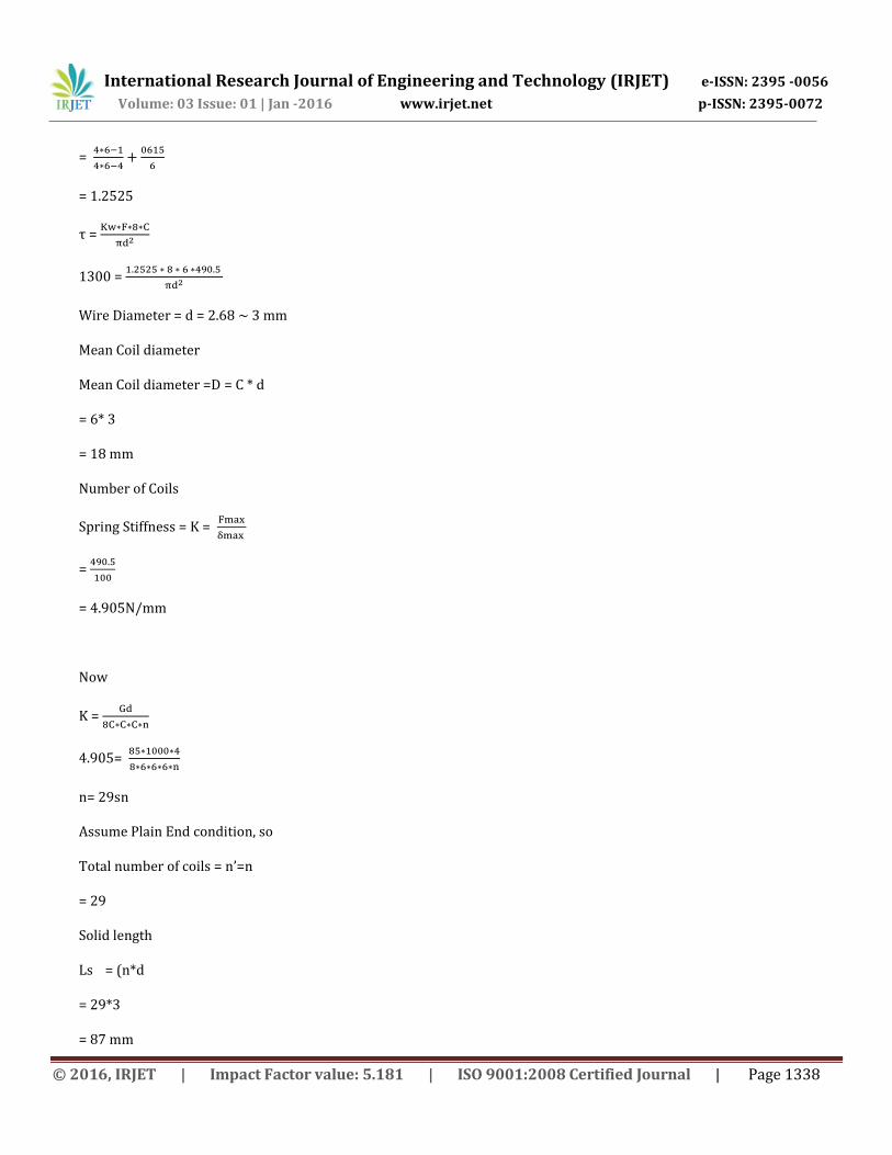
=
= 1.2525
τ =
1300 =
Wire Diameter = d = 2.68 ~ 3 mm
Mean Coil diameter
Mean Coil diameter =D = C * d
= 6* 3
= 18 mm
Number of Coils
Spring Stiffness = K =
=
= 4.905N/mm
Now
K =
4.905=
n= 29sn
Assume Plain End condition, so
Total number of coils = n’=n
= 29
Solid length
Ls = (n*d
= 29*3
= 87 mm
International Research Journal of Engineering and Technology (IRJET) e-ISSN: 2395 -0056
Volume: 03 Issue: 01 | Jan -2016 www.irjet.net p-ISSN: 2395-0072
© 2016, IRJET | Impact Factor value: 5.181 | ISO 9001:2008 Certified Journal | Page 1339
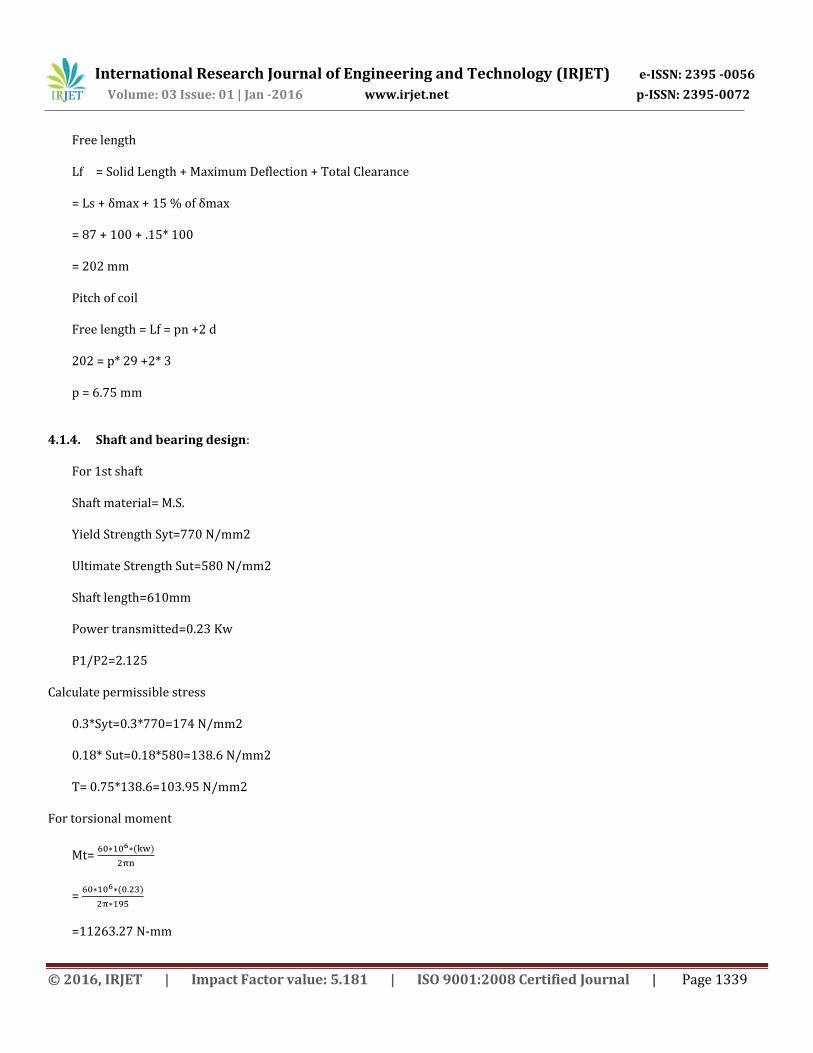
Free length
Lf = Solid Length + Maximum Deflection + Total Clearance
= Ls + δmax + 15 % of δmax
= 87 + 100 + .15* 100
= 202 mm
Pitch of coil
Free length = Lf = pn +2 d
202 = p* 29 +2* 3
p = 6.75 mm
4.1.4. Shaft and bearing design:
For 1st shaft
Shaft material= M.S.
Yield Strength Syt=770 N/mm2
Ultimate Strength Sut=580 N/mm2
Shaft length=610mm
Power transmitted=0.23 Kw
P1/P2=2.125
Calculate permissible stress
0.3*Syt=0.3*770=174 N/mm2
0.18* Sut=0.18*580=138.6 N/mm2
Τ= 0.75*138.6=103.95 N/mm2
For torsional moment
Mt=
=
=11263.27 N-mm
International Research Journal of Engineering and Technology (IRJET) e-ISSN: 2395 -0056
Volume: 03 Issue: 01 | Jan -2016 www.irjet.net p-ISSN: 2395-0072
© 2016, IRJET | Impact Factor value: 5.181 | ISO 9001:2008 Certified Journal | Page 1340
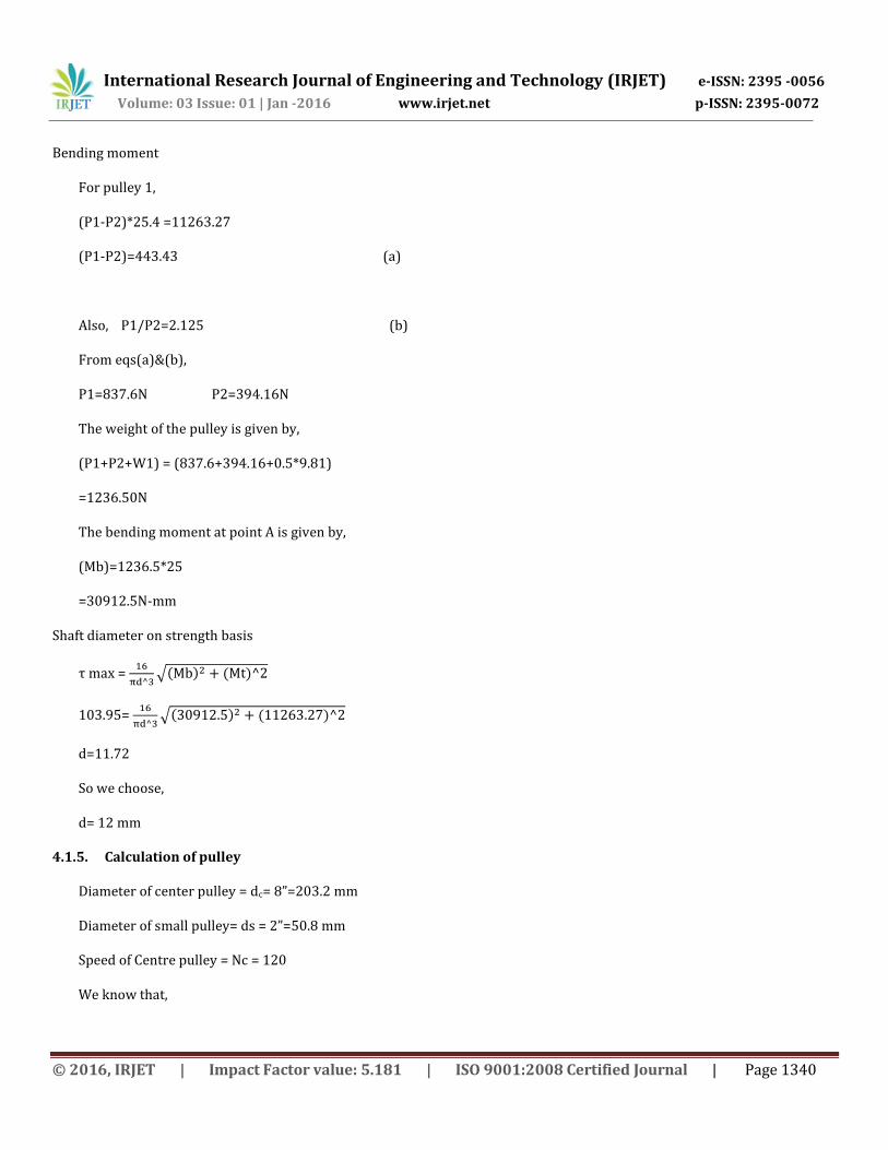
Bending moment
For pulley 1,
(P1-P2)*25.4 =11263.27
(P1-P2)=443.43 (a)
Also, P1/P2=2.125 (b)
From eqs(a)&(b),
P1=837.6N P2=394.16N
The weight of the pulley is given by,
(P1+P2+W1) = (837.6+394.16+0.5*9.81)
=1236.50N
The bending moment at point A is given by,
(Mb)=1236.5*25
=30912.5N-mm
Shaft diameter on strength basis
τ max =
√
103.95=
√
d=11.72
So we choose,
d= 12 mm
4.1.5. Calculation of pulley
Diameter of center pulley = dc= 8”=203.2 mm
Diameter of small pulley= ds = 2”=50.8 mm
Speed of Centre pulley = Nc = 120
We know that,
International Research Journal of Engineering and Technology (IRJET) e-ISSN: 2395 -0056
Volume: 03 Issue: 01 | Jan -2016 www.irjet.net p-ISSN: 2395-0072
© 2016, IRJET | Impact Factor value: 5.181 | ISO 9001:2008 Certified Journal | Page 1341
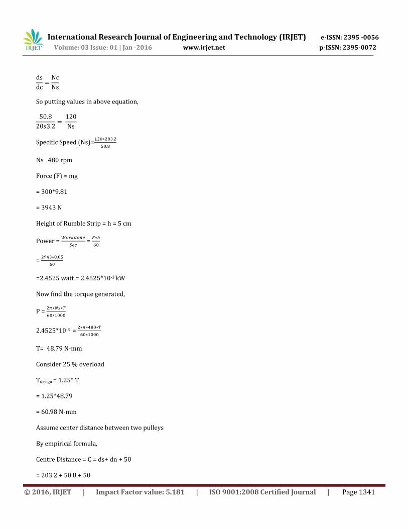
So putting values in above equation,
Specific Speed (Ns)=
Ns = 480 rpm
Force (F) = mg
= 300*9.81
= 3943 N
Height of Rumble Strip = h = 5 cm
Power =
=
=
=2.4525 watt = 2.4525*10-3 kW
Now find the torque generated,
P =
2.4525*10-3 =
T= 48.79 N-mm
Consider 25 % overload
Tdesign = 1.25* T
= 1.25*48.79
= 60.98 N-mm
Assume center distance between two pulleys
By empirical formula,
Centre Distance = C = ds+ dn + 50
= 203.2 + 50.8 + 50
International Research Journal of Engineering and Technology (IRJET) e-ISSN: 2395 -0056
Volume: 03 Issue: 01 | Jan -2016 www.irjet.net p-ISSN: 2395-0072
© 2016, IRJET | Impact Factor value: 5.181 | ISO 9001:2008 Certified Journal | Page 1342
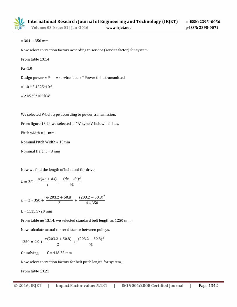
= 304 ~ 350 mm
Now select correction factors according to service (service factor) for system,
From table 13.14
Fa=1.0
Design power = Pd = service factor * Power to be transmitted
= 1.0 * 2.4525*10-3
= 2.4525*10-3 kW
We selected V-belt type according to power transmission,
From figure 13.24 we selected as “A” type V-belt which has,
Pitch width = 11mm
Nominal Pitch Width = 13mm
Nominal Height = 8 mm
Now we find the length of belt used for drive,
L = 1115.5720 mm
From table no 13.14, we selected standard belt length as 1250 mm.
Now calculate actual center distance between pulleys,
On solving, C = 418.22 mm
Now select correction factors for belt pitch length for system,
From table 13.21
International Research Journal of Engineering and Technology (IRJET) e-ISSN: 2395 -0056
Volume: 03 Issue: 01 | Jan -2016 www.irjet.net p-ISSN: 2395-0072
© 2016, IRJET | Impact Factor value: 5.181 | ISO 9001:2008 Certified Journal | Page 1343
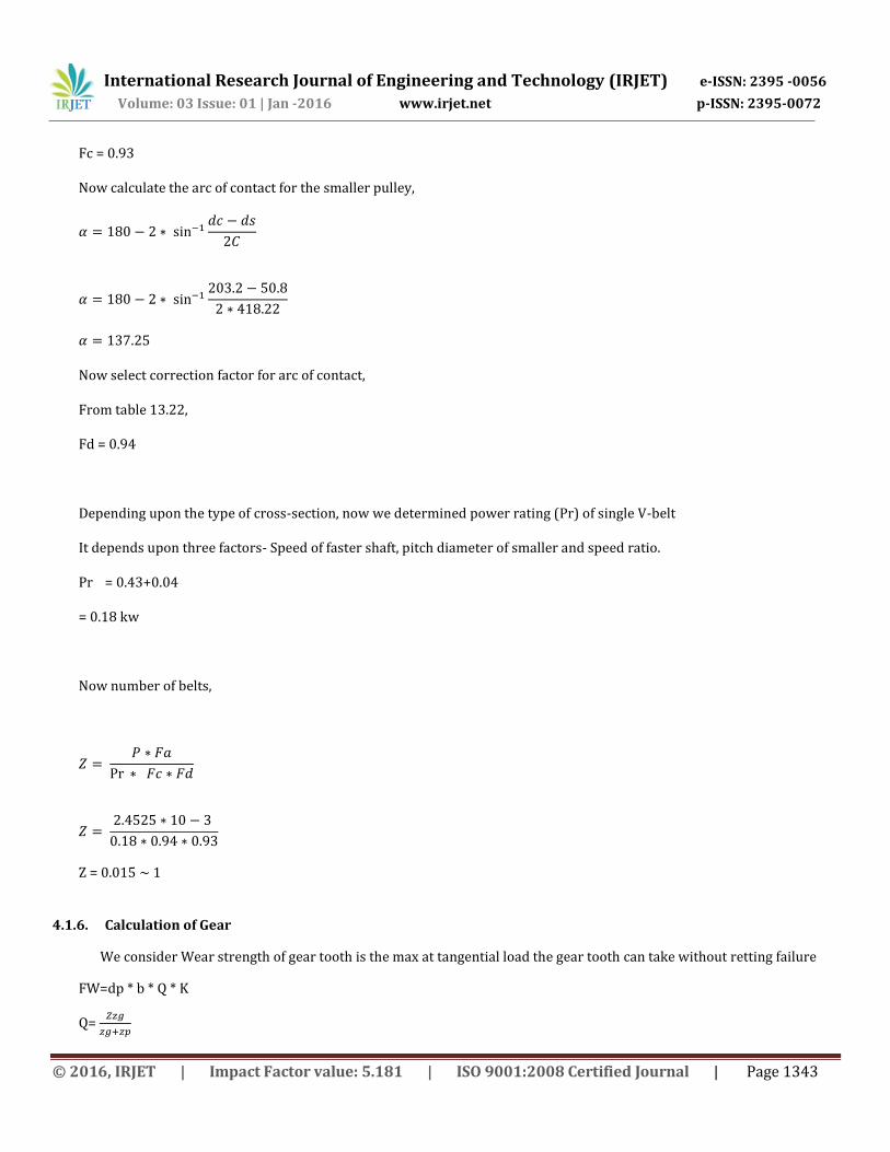
Fc = 0.93
Now calculate the arc of contact for the smaller pulley,
Now select correction factor for arc of contact,
From table 13.22,
Fd = 0.94
Depending upon the type of cross-section, now we determined power rating (Pr) of single V-belt
It depends upon three factors- Speed of faster shaft, pitch diameter of smaller and speed ratio.
Pr = 0.43+0.04
= 0.18 kw
Now number of belts,
Z = 0.015 1
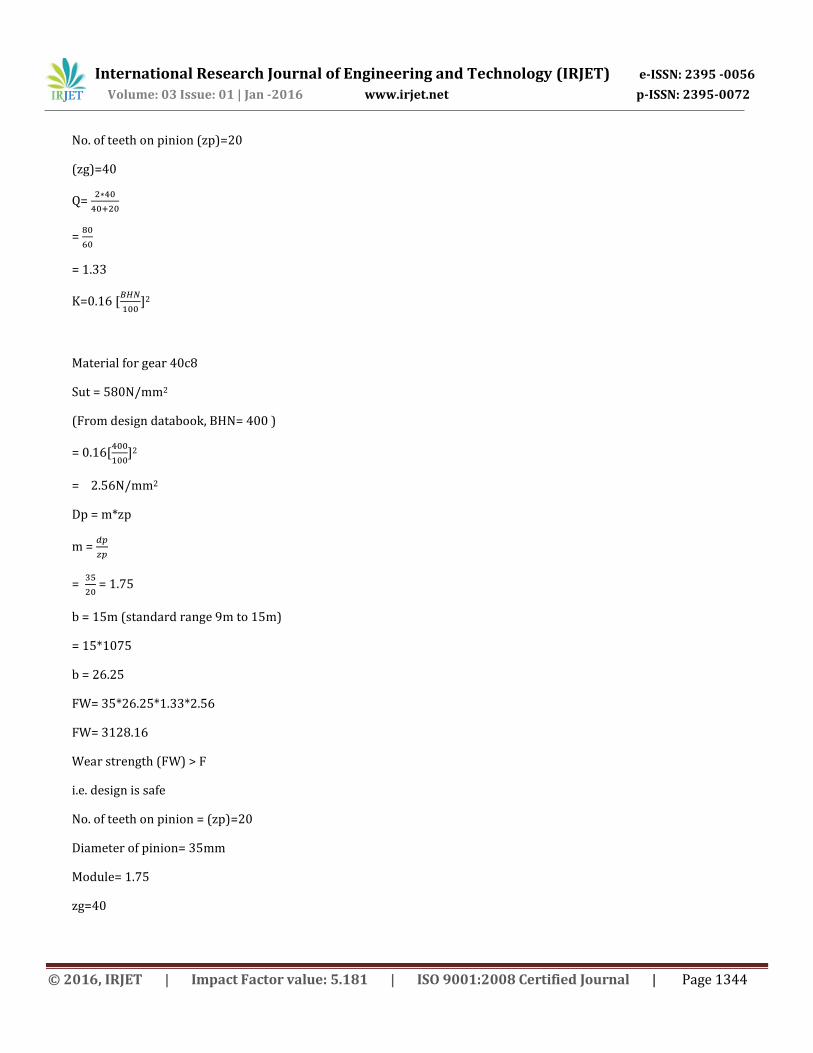
4.1.6. Calculation of Gear
We consider Wear strength of gear tooth is the max at tangential load the gear tooth can take without retting failure
FW=dp * b * Q * K
Q=
International Research Journal of Engineering and Technology (IRJET) e-ISSN: 2395 -0056
Volume: 03 Issue: 01 | Jan -2016 www.irjet.net p-ISSN: 2395-0072
© 2016, IRJET | Impact Factor value: 5.181 | ISO 9001:2008 Certified Journal | Page 1344
No. of teeth on pinion (zp)=20
(zg)=40
Q=
=
= 1.33
K=0.16 [
]2
Material for gear 40c8
Sut = 580N/mm2
(From design databook, BHN= 400 )
= 0.16[
]2
= 2.56N/mm2
Dp = m*zp
m =
=
= 1.75
b = 15m (standard range 9m to 15m)
= 15*1075
b = 26.25
FW= 35*26.25*1.33*2.56
FW= 3128.16
Wear strength (FW) > F
i.e. design is safe
No. of teeth on pinion = (zp)=20
Diameter of pinion= 35mm
Module= 1.75
zg=40
International Research Journal of Engineering and Technology (IRJET) e-ISSN: 2395 -0056
Volume: 03 Issue: 01 | Jan -2016 www.irjet.net p-ISSN: 2395-0072
© 2016, IRJET | Impact Factor value: 5.181 | ISO 9001:2008 Certified Journal | Page 1345
5. RESULT When a vehicle passes over a one rumbler, the load acting on it produces 10-12 watts of power. The power produced by each stepper motor is 5-6 watts. So, therefore the total power produced by 4 stepper motors altogether is approx. 20 watts per second. This would result in 1.2 Kw per min and a total of 72Kw per hour and 1728 Kw per day.
6. CONCLUSIONS: Such rumbler can be designed for heavy vehicles, thus increasing input torque and ultimately output of generator. It can
also be used for light vehicles. More suitable and compact mechanism to enhance efficiency of usage of energy. A survey on the energy consumption in India had published a pathetic report that 85,000 villages in India do not still
have electricity. Supply of power in most of the country is poor. Hence more research and development of technologies are needed in this field. This energy can be used for the lights on the either sides of the roads and thus power that is consumed by these lights can be utilized to send power to these villages.
7. REFERENCES:
1. Ch.Bhanu Prakash, A.V.Ramana Rao, P.Srinuvas; “ Road Power Generation by Speed Breakers”, International Journal of Engineering Trends and Technology (IJETT) – Volume 11 Number 2 - May 2014
2. Mr. Swapnil Kamthe, Mr. Rahul Kadam, Mr. Aniket Dhore, Mr. Shivkumar Falmari, Prof. Subhash Ghadve, Prof. Mukesh Chaudhari “Development Of Mechanism For Recovery Of Energy Of Suspension System.”
3. Zhang Jin-Qiu, Peng Zhi-Zhao*, Zhang Lei, Zhang Yu “A Review On Energy-Regenerative Suspension Systems For Vehicles”