Embed Size (px)
Citation preview
POW
ER
GEN
ERA
TIO
N

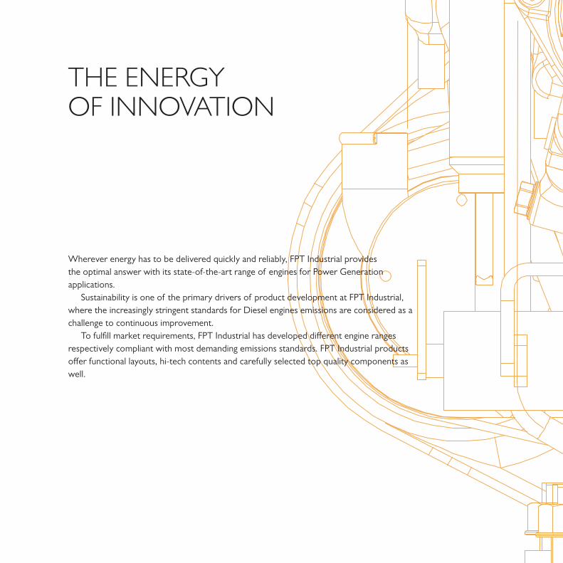
THE ENERGYOF INNOVATION
Wherever energy has to be delivered quickly and reliably, FPT Industrial provides the optimal answer with its state-of-the-art range of engines for Power Generation applications.
Sustainability is one of the primary drivers of product development at FPT Industrial, where the increasingly stringent standards for Diesel engines emissions are considered as a challenge to continuous improvement.
To fulfill market requirements, FPT Industrial has developed different engine ranges respectively compliant with most demanding emissions standards. FPT Industrial products offer functional layouts, hi-tech contents and carefully selected top quality components as well.
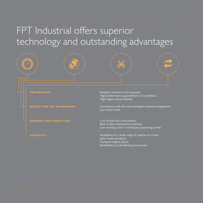
Excellent transient load responseHigh performance guaranteed in all conditionsHigh engine power density
Compliance with the most stringent emissions legislationsLow noise levels
Low oil and fuel consumptionBest in class maintenance intervals Low running costs in continuous operating power
Availability of a wide range of options to create tailor-made productsCompact engine layoutAvailability of cold starting accessories
PERFORMANCE
RESPECT FOR THE ENVIRONMENT
RUNNING COSTS REDUCTION
FLEXIBILITY
FPT Industrial offers superior technology and outstanding advantages
STAND-BY POWER OUTPUT [kWm]
PRIMEPOWER OUTPUT [kWm]
1500 RPM 1800 RPM 1500 RPM 1800 RPM
F32 AM1A 4L / NA M 3,2 31,5 – UR1 29 –
F32 SM1A 4L / TC M 3,2 41,5 – UR1 38 –
F32 TM1A 4L / TAA M 3,2 51,5 – UR1 47 –
F32 SM1F 4L / TC / I-EGR M 3,2 31,5 – Stage IIIA 29
F32 SM1X 4L / TC / I-EGR M 3,2 – 46,5 Tier 3 – 42
F32 TM1X 4L / TAA / I-EGR M 3,2 – 56,5 Tier 3 – 52
N45 AM2 4L / NA M 4,5 50 – UR 45 –
N45 SM3 4L / TC M 4,5 81 87 UR 73 79
N45 TM3 4L / TAA M 4,5 118 – UR 107 –
N45 AM1A 4L / NA M 4,5 46 – UR1 42 –
N45 SM1A 4L / TC M 4,5 59 65 UR1 53 59
N45 SM2A 4L / TC M 4,5 73 – UR1 66 –
N45 TM1A 4L / TAA M 4,5 85 95 UR1 78 87
N45 TM2A 4L / TAA M 4,5 96 107 UR1 88 98
N45 SM1F 4L / TC / I-EGR M 4,5 60 – Stage IIIA 55 –
N45 TE1F 4L / TAA / I-EGR ECR 4,5 80 – Stage IIIA 73 –
N45 TE2F 4L / TAA / I-EGR ECR 4,5 98 – Stage IIIA 89 –
N45 SM1X 4L / TC / I-EGR M 4,5 – 57 Tier 3 – 53
N45 SM2X 4L / TC / I-EGR M 4,5 – 67 Tier 3 – 61
N45 TM2X 4L / TAA / I-EGR M 4,5 – 95 Tier 3 – 87
N67 SM1 6L / TC M 6,7 121 138 UR 110 125
N67 TM4 6L / TAA M 6,7 165 – UR 150N67 TM7 6L / TAA M 6,7 194 – UR 176 –
N67 TM2A 6L / TAA M 6,7 126 141 UR1 114 128
N67 TM3A 6L / TAA M 6,7 152 165 UR1 138 149
N67 TE2A 6L / TAA ECR 6,7 193 215 UR1 175 195
N67 TM1F 6L / TAA / I-EGR M 6,7 125 – Stage IIIA 114 –
N67 TE1F 6L / TAA / I-EGR ECR 6,7 145 – Stage IIIA 132 –
N67 TE2F 6L / TAA / I-EGR ECR 6,7 165 – Stage IIIA 150 –
N67 TE3F 6L / TAA / I-EGR ECR 6,7 194 – Stage IIIA 175
N67 TM1X 6L / TAA / I-EGR M 6,7 – 141 Tier 3 – 128
N67 TE1X 6L / TAA / I-EGR ECR 6,7 – 165 Tier 3 – 150
N67 TE2X 6L / TAA / I-EGR ECR 6,7 – 200 Tier 3 – 182
INJEC
TION SY
STEM
DISPLA
CEMEN
T
LITER
S
MODELCY
LINDER
ARRA
NGEMEN
T
AIR IN
TAKE
EXHAU
ST SY
STEM
EMISS
IONS
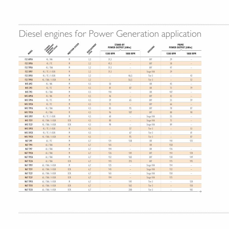
Diesel engines for Power Generation application
STAND-BY POWER OUTPUT [kWm]
PRIMEPOWER OUTPUT [kWm]
1500 RPM 1800 RPM 1500 RPM 1800 RPM
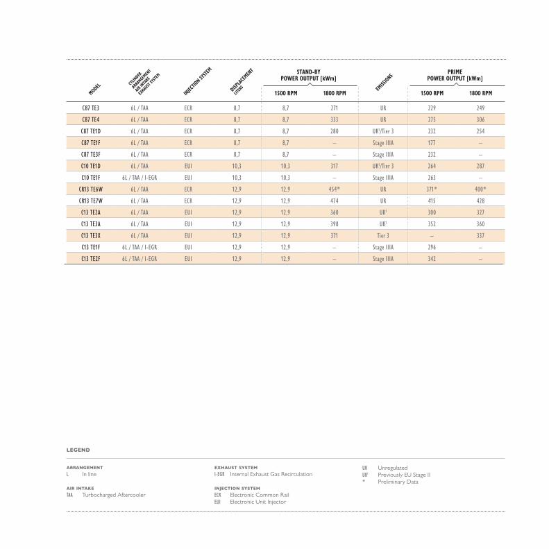
C87 TE3 6L / TAA ECR 8,7 249 271 UR 229 249
C87 TE4 6L / TAA ECR 8,7 299 333 UR 275 306
C87 TE1D 6L / TAA ECR 8,7 256 280 UR1/Tier 3 232 254
C87 TE1F 6L / TAA ECR 8,7 195 – Stage IIIA 177 –
C87 TE3F 6L / TAA ECR 8,7 256 – Stage IIIA 232 –
C10 TE1D 6L / TAA EUI 10,3 290 317 UR1/Tier 3 264 287
C10 TE1F 6L / TAA / I-EGR EUI 10,3 290 – Stage IIIA 263 –
CR13 TE6W 6L / TAA ECR 12,9 417* 454* UR 371* 400*
CR13 TE7W 6L / TAA ECR 12,9 459 474 UR 415 428
C13 TE2A 6L / TAA EUI 12,9 330 360 UR1 300 327
C13 TE3A 6L / TAA EUI 12,9 387 398 UR1 352 360
C13 TE3X 6L / TAA EUI 12,9 – 371 Tier 3 – 337
C13 TE1F 6L / TAA / I-EGR EUI 12,9 327 – Stage IIIA 296 –
C13 TE2F 6L / TAA / I-EGR EUI 12,9 377 – Stage IIIA 342 –
INJEC
TION SY
STEM
DISPLA
CEMEN
T
LITER
S
MODELCY
LINDER
ARRA
NGEMEN
T
AIR IN
TAKE
EXHAU
ST SY
STEM
EMISS
IONS
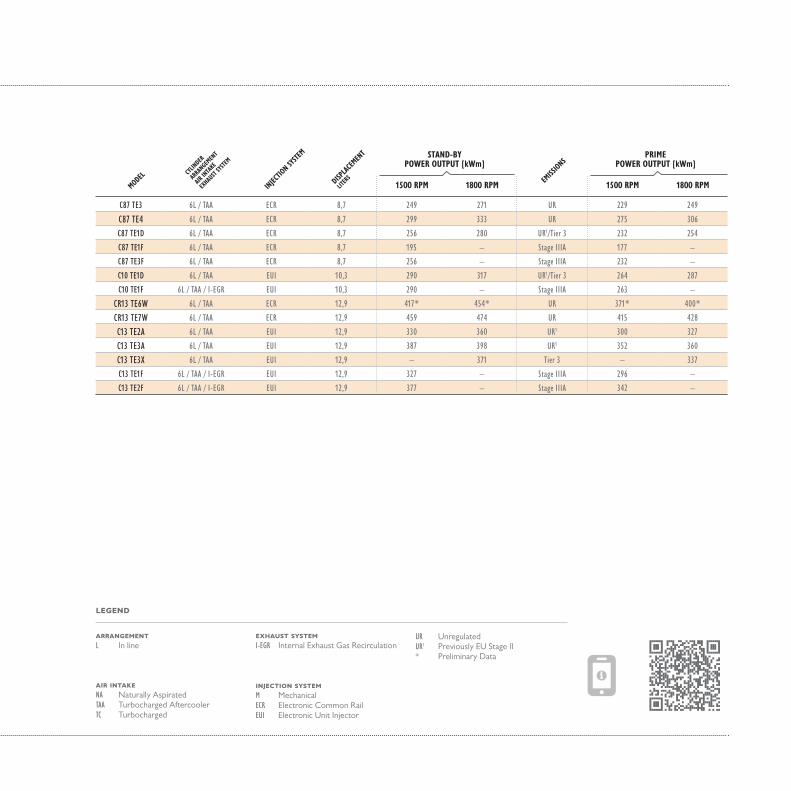
LEGEND
EXHAUST SYSTEMI-EGR Internal Exhaust Gas Recirculation
INJECTION SYSTEMM MechanicalECR Electronic Common RailEUI Electronic Unit Injector
ARRANGEMENT L In line
UR UnregulatedUR1 Previously EU Stage II* Preliminary Data
AIR INTAKENA Naturally AspiratedTAA Turbocharged AftercoolerTC Turbocharged


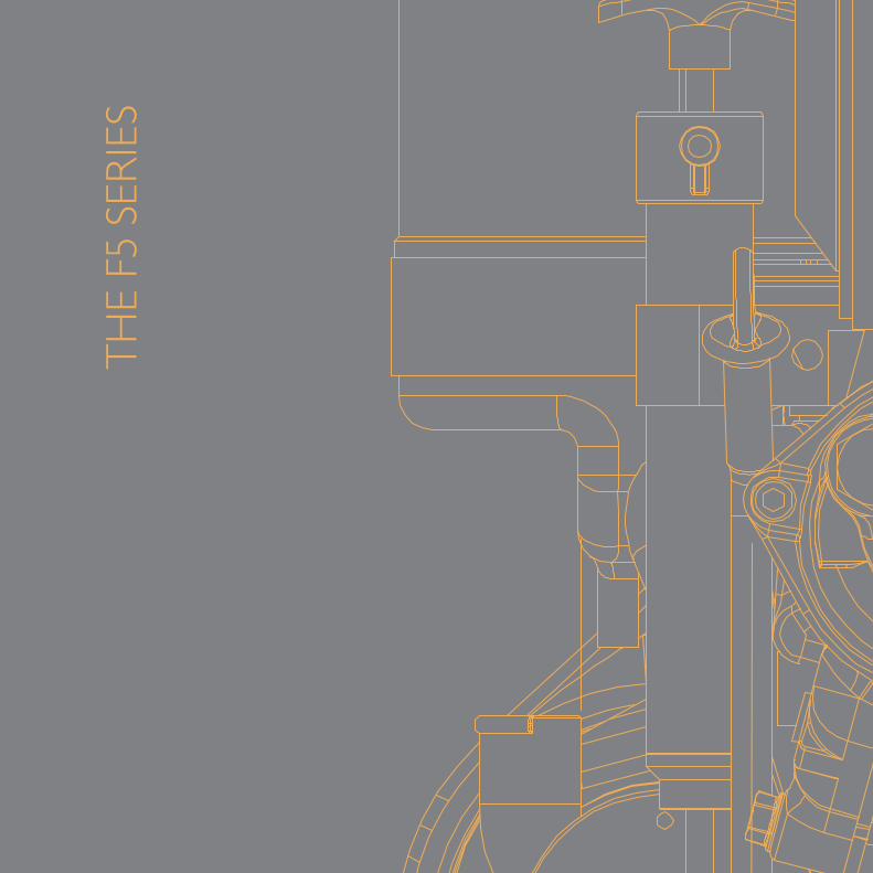
THE
F5 S
ERIE
S
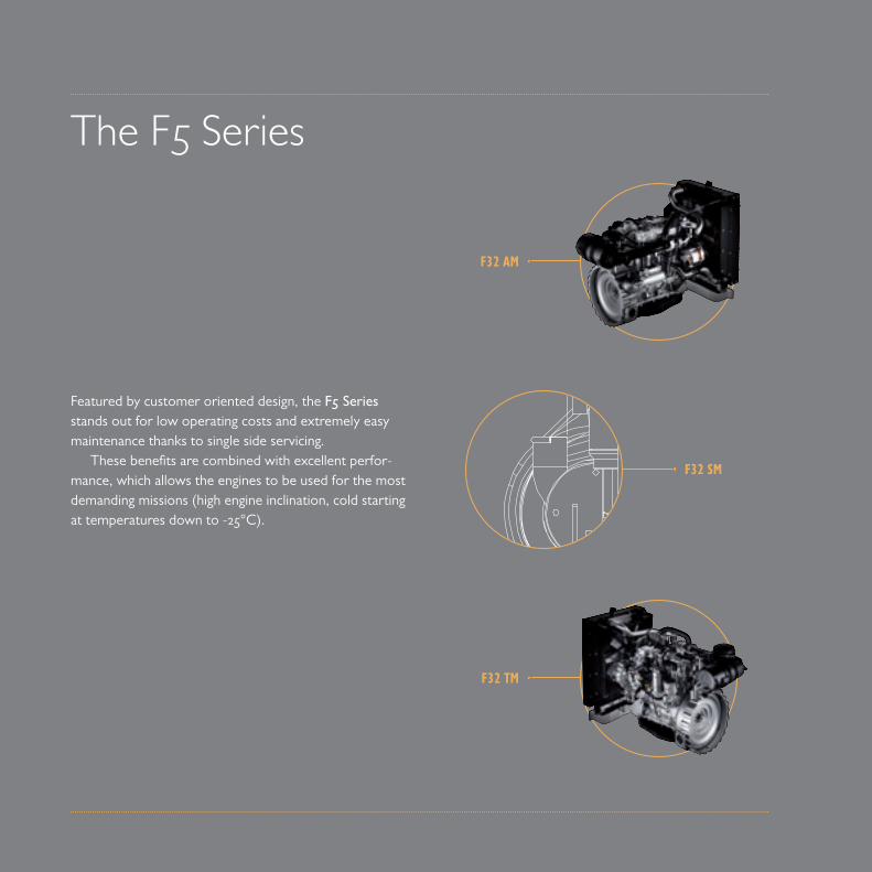
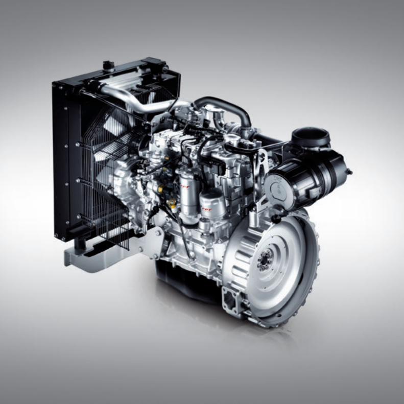
Featured by customer oriented design, the F5 Series stands out for low operating costs and extremely easy maintenance thanks to single side servicing.
These benefits are combined with excellent perfor-mance, which allows the engines to be used for the most demanding missions (high engine inclination, cold starting at temperatures down to -25°C).
The F5 Series
F32 AM
F32 TM
F32 SM
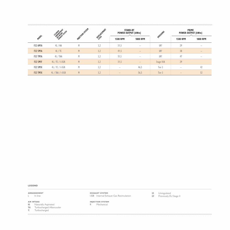
STAND-BYPOWER OUTPUT [kWm]
PRIMEPOWER OUTPUT [kWm]
1500 RPM 1800 RPM 1500 RPM 1800 RPM
F32 AM1A 4L / NA M 3,2 3 1,5 – UR1 29 –
F32 SM1A 4L / TC M 3,2 4 1,5 – UR1 38 –
F32 TM1A 4L / TAA M 3,2 51,5 – UR1 47 –
F32 SM1F 4L / TC / I-EGR M 3,2 3 1,5 – Stage IIIA 29
F32 SM1X 4L / TC / I-EGR M 3,2 – 46,5 Tier 3 – 42
F32 TM1X 4L / TAA / I-EGR M 3,2 – 56,5 Tier 3 – 52
LEGEND
MODELCY
LINDER
ARRA
NGEMEN
T
AIR IN
TAKE
EXHAU
ST SY
STEM
EMISS
IONS
INJEC
TION SY
STEM
DISPLA
CEMEN
T
LITER
S
ARRANGEMENTL In line
AIR INTAKENA Naturally AspiratedTAA Turbocharged AftercoolerTC Turbocharged
EXHAUST SYSTEMI-EGR Internal Exhaust Gas Recirculation
INJECTION SYSTEMM Mechanical
UR UnregulatedUR1 Previously EU Stage II

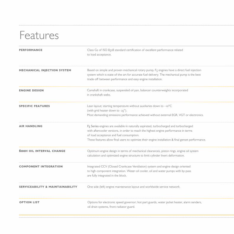
FeaturesClass G2 of ISO 8528 standard certification of excellent performance relatedto load acceptance.
PERFORMANCE
Based on simple and proven mechanical rotary pump, F5 engines have a direct fuel injection system which is state-of-the-art for accurate fuel delivery. The mechanical pump is the best trade-off between performance and easy engine installation.
MECHANICAL INJECTION SYSTEM
Camshaft in crankcase, suspended oil pan, balancer counterweights incorporatedin crankshaft webs.
ENGINE DESIGN
Lean layout; starting temperature without auxiliaries down to –10°C (with grid heater down to -25°).Most demanding emissions performance achieved without external EGR, VGT or electronics.
SPECIFIC FEATURES
F5 Series engines are available in naturally aspirated, turbocharged and turbocharged with aftercooler versions, in order to reach the highest engine performance in terms of load acceptance and fuel consumption. These features allow final users to optimize their engine installation & final genset performance.
AIR HANDLING
Optimum engine design in terms of mechanical clearances, piston rings, engine oil system calculation and optimized engine structure to limit cylinder liners deformation.
600H OIL INTERVAL CHANGE
Integrated CCV (Closed Crankcase Ventilation) system and engine design oriented to high component integration. Water-oil cooler, oil and water pumps with by-pass are fully integrated in the block.
COMPONENT INTEGRATION
Options for electronic speed governor; hot part guards, water jacket heater, alarm senders, oil drain systems, front radiator guard.
OPTION LIST
One side (left) engine maintenance layout and worldwide service network.SERVICEABILITY & MAINTAINABILITY
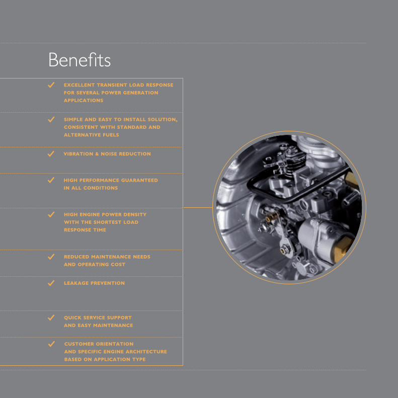
BenefitsEXCELLENT TRANSIENT LOAD RESPONSE FOR SEVERAL POWER GENERATION APPLICATIONS
SIMPLE AND EASY TO INSTALL SOLUTION, CONSISTENT WITH STANDARD AND ALTERNATIVE FUELS
VIBRATION & NOISE REDUCTION
HIGH PERFORMANCE GUARANTEEDIN ALL CONDITIONS
HIGH ENGINE POWER DENSITY WITH THE SHORTEST LOAD RESPONSE TIME
REDUCED MAINTENANCE NEEDSAND OPERATING COST
LEAKAGE PREVENTION
CUSTOMER ORIENTATIONAND SPECIFIC ENGINE ARCHITECTURE BASED ON APPLICATION TYPE
QUICK SERVICE SUPPORTAND EASY MAINTENANCE

THE
NEF
SER
IES
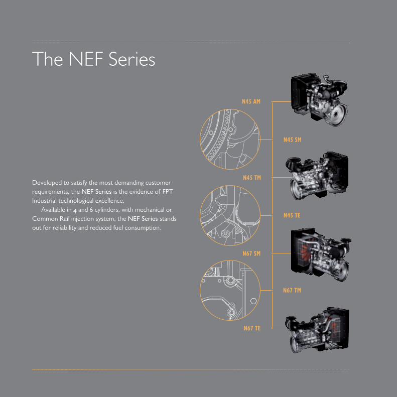
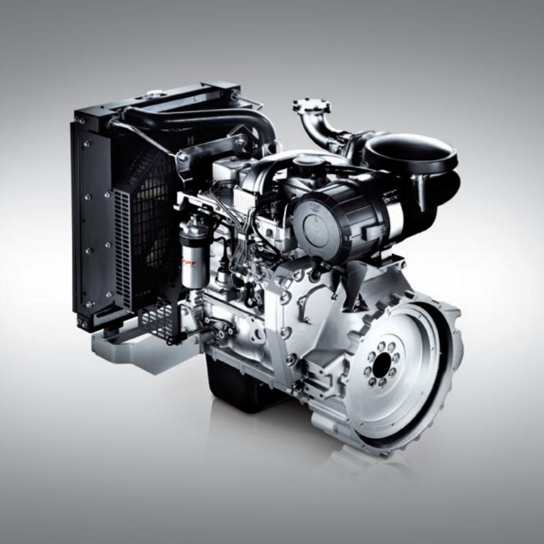
Developed to satisfy the most demanding customer requirements, the NEF Series is the evidence of FPT Industrial technological excellence.
Available in 4 and 6 cylinders, with mechanical or Common Rail injection system, the NEF Series stands out for reliability and reduced fuel consumption.
The NEF Series
N45 AM
N45 SM
N45 TM
N67 SM
N45 TE
N67 TM
N67 TENef
NefNef
STAND-BY POWER OUTPUT [kWm]
PRIMEPOWER OUTPUT [kWm]
1500 RPM 1800 RPM 1500 RPM 1800 RPM
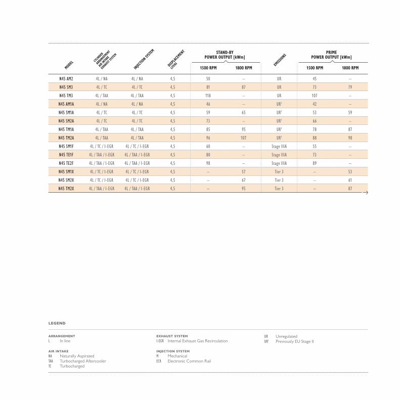
N45 AM2 4L / NA 4L / NA 4,5 50 – UR 45 –
N45 SM3 4L / TC 4L / TC 4,5 81 87 UR 73 79
N45 TM3 4L / TAA 4L / TAA 4,5 118 – UR 107 –
N45 AM1A 4L / NA 4L / NA 4,5 46 – UR1 42 –
N45 SM1A 4L / TC 4L / TC 4,5 59 65 UR1 53 59
N45 SM2A 4L / TC 4L / TC 4,5 73 – UR1 66 –
N45 TM1A 4L / TAA 4L / TAA 4,5 85 95 UR1 78 87
N45 TM2A 4L / TAA 4L / TAA 4,5 96 107 UR1 88 98
N45 SM1F 4L / TC / I-EGR 4L / TC / I-EGR 4,5 60 – Stage IIIA 55 –
N45 TE1F 4L / TAA / I-EGR 4L / TAA / I-EGR 4,5 80 – Stage IIIA 73 –
N45 TE2F 4L / TAA / I-EGR 4L / TAA / I-EGR 4,5 98 – Stage IIIA 89 –
N45 SM1X 4L / TC / I-EGR 4L / TC / I-EGR 4,5 – 57 Tier 3 – 53
N45 SM2X 4L / TC / I-EGR 4L / TC / I-EGR 4,5 – 67 Tier 3 – 61
N45 TM2X 4L / TAA / I-EGR 4L / TAA / I-EGR 4,5 – 95 Tier 3 – 87
INJEC
TION SY
STEM
DISPLA
CEMEN
T
LITER
S
MODELCY
LINDER
ARRA
NGEMEN
T
AIR IN
TAKE
EXHAU
ST SY
STEM
EMISS
IONS
LEGEND
ARRANGEMENTL In line
AIR INTAKENA Naturally AspiratedTAA Turbocharged AftercoolerTC Turbocharged
EXHAUST SYSTEMI-EGR Internal Exhaust Gas Recirculation
INJECTION SYSTEMM MechanicalECR Electronic Common Rail
UR UnregulatedUR1 Previously EU Stage II
STAND-BYPOWER OUTPUT [kWm]
PRIMEPOWER OUTPUT [kWm]
1500 RPM 1800 RPM 1500 RPM 1800 RPM
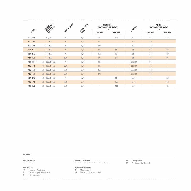
N67 SM1 6L / TC M 6,7 121 138 UR 110 125
N67 TM4 6L / TAA M 6,7 165 – UR 150
N67 TM7 6L / TAA M 6,7 194 – UR 176 –
N67 TM2A 6L / TAA M 6,7 126 141 UR1 114 128
N67 TM3A 6L / TAA M 6,7 152 165 UR1 138 149
N67 TE2A 6L / TAA ECR 6,7 193 215 UR1 175 195
N67 TM1F 6L / TAA / I-EGR M 6,7 125 – Stage IIIA 114 –
N67 TE1F 6L / TAA / I-EGR ECR 6,7 145 – Stage IIIA 132 –
N67 TE2F 6L / TAA / I-EGR ECR 6,7 165 – Stage IIIA 150 –
N67 TE3F 6L / TAA / I-EGR ECR 6,7 194 – Stage IIIA 175
N67 TM1X 6L / TAA / I-EGR M 6,7 – 141 Tier 3 – 128
N67 TE1X 6L / TAA / I-EGR ECR 6,7 – 165 Tier 3 – 150
N67 TE2X 6L / TAA / I-EGR ECR 6,7 – 200 Tier 3 – 182
INJEC
TION SY
STEM
DISPLA
CEMEN
T
LITER
S
MODELCY
LINDER
ARRA
NGEMEN
T
AIR IN
TAKE
EXHAU
ST SY
STEM
EMISS
IONS
LEGEND
ARRANGEMENTL In line
AIR INTAKENA Naturally AspiratedTAA Turbocharged AftercoolerTC Turbocharged
EXHAUST SYSTEMI-EGR Internal Exhaust Gas Recirculation
INJECTION SYSTEMM MechanicalECR Electronic Common Rail
UR UnregulatedUR1 Previously EU Stage II
Mechanical Engines – Features Class G2 of ISO 8528 standard certification of excellent performance related to load acceptance.
PERFORMANCE
Mechanical rotary pump, easy to maintain, is the core of the NEF mechanical engine series. The system, is based on direct fuel injection for accurate fuel delivery and is adaptive with standard and alternative fuels. The NEF mechanical injection system is the best trade-off between product cost effectiveness and performance.
INJECTION SYSTEM
Possibility to switch from 1500 rpm to 1800 rpm (only one homologation engine rate).DUAL SPEED MODE
Minimum cold starting temperature without auxiliaries down to -10°C (with grid heater down to -25°).Tier 3 and Stage IIIA performances achieved without external EGR or VGT.
SPECIFIC FEATURES
NEF Series engines are available in naturally aspirated, turbocharged and turbocharged with aftercooler versions in order to reach the highest engine performance in terms of load acceptance & fuel consumption. These features allow final users to optimize their engine installation & final genset performance.
AIR HANDLING
NEF Series adopts combustion chambers optimized to reduce oil dilution and are designed with an optimum engine design in terms of mechanical clearances, piston rings andengine oil system calculation.
UP TO 800H OIL INTERVAL CHANGE
Worldwide service network. Engines featured with a proven mechanical injection system without electronic interfaces and without external EGR.
SERVICEABILITY & MAINTAINABILITY
Options for electronic speed governor; hot part guards, water jacket heater, alarm senders, oil drain systems, front radiator guard.
OPTION LIST
Balancer counterweights incorporated in crankshaft webs, rear gear train layout, camshaft in crankcase, suspended oil pan, ladder frame cylinder block.
ENGINE DESIGN
Integrated CCV (Closed Crankcase Ventilation) system and engine design oriented to high component integration. Water-oil cooler, oil and water pumps are completely integrated in the engine block.
COMPONENT INTEGRATION
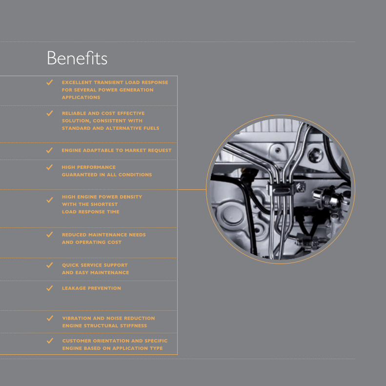
BenefitsEXCELLENT TRANSIENT LOAD RESPONSE FOR SEVERAL POWER GENERATIONAPPLICATIONS
RELIABLE AND COST EFFECTIVE SOLUTION, CONSISTENT WITH STANDARD AND ALTERNATIVE FUELS
ENGINE ADAPTABLE TO MARKET REQUEST
HIGH PERFORMANCEGUARANTEED IN ALL CONDITIONS
HIGH ENGINE POWER DENSITYWITH THE SHORTESTLOAD RESPONSE TIME
REDUCED MAINTENANCE NEEDSAND OPERATING COST
QUICK SERVICE SUPPORTAND EASY MAINTENANCE
CUSTOMER ORIENTATION AND SPECIFIC ENGINE BASED ON APPLICATION TYPE
VIBRATION AND NOISE REDUCTIONENGINE STRUCTURAL STIFFNESS
LEAKAGE PREVENTION
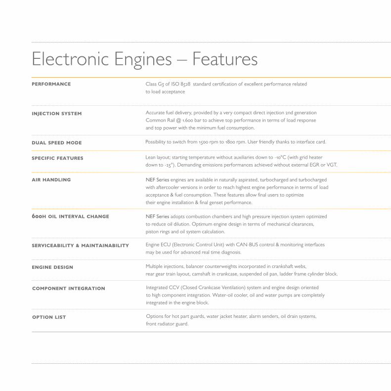
Electronic Engines – Features Class G3 of ISO 8528 standard certification of excellent performance related to load acceptance
PERFORMANCE
Accurate fuel delivery, provided by a very compact direct injection 2nd generation Common Rail @ 1.600 bar to achieve top performance in terms of load response and top power with the minimum fuel consumption.
INJECTION SYSTEM
Possibility to switch from 1500 rpm to 1800 rpm. User friendly thanks to interface card.DUAL SPEED MODE
Lean layout; starting temperature without auxiliaries down to -10°C (with grid heater down to -25°). Demanding emissions performances achieved without external EGR or VGT.
SPECIFIC FEATURES
NEF Series engines are available in naturally aspirated, turbocharged and turbocharged with aftercooler versions in order to reach highest engine performance in terms of load acceptance & fuel consumption. These features allow final users to optimize their engine installation & final genset performance.
AIR HANDLING
NEF Series adopts combustion chambers and high pressure injection system optimized to reduce oil dilution. Optimum engine design in terms of mechanical clearances, piston rings and oil system calculation.
600H OIL INTERVAL CHANGE
Engine ECU (Electronic Control Unit) with CAN-BUS control & monitoring interfaces may be used for advanced real time diagnosis.
SERVICEABILITY & MAINTAINABILITY
Options for hot part guards, water jacket heater, alarm senders, oil drain systems,front radiator guard.
OPTION LIST
Integrated CCV (Closed Crankcase Ventilation) system and engine design oriented to high component integration. Water-oil cooler, oil and water pumps are completely integrated in the engine block.
COMPONENT INTEGRATION
Multiple injections, balancer counterweights incorporated in crankshaft webs, rear gear train layout, camshaft in crankcase, suspended oil pan, ladder frame cylinder block.
ENGINE DESIGN
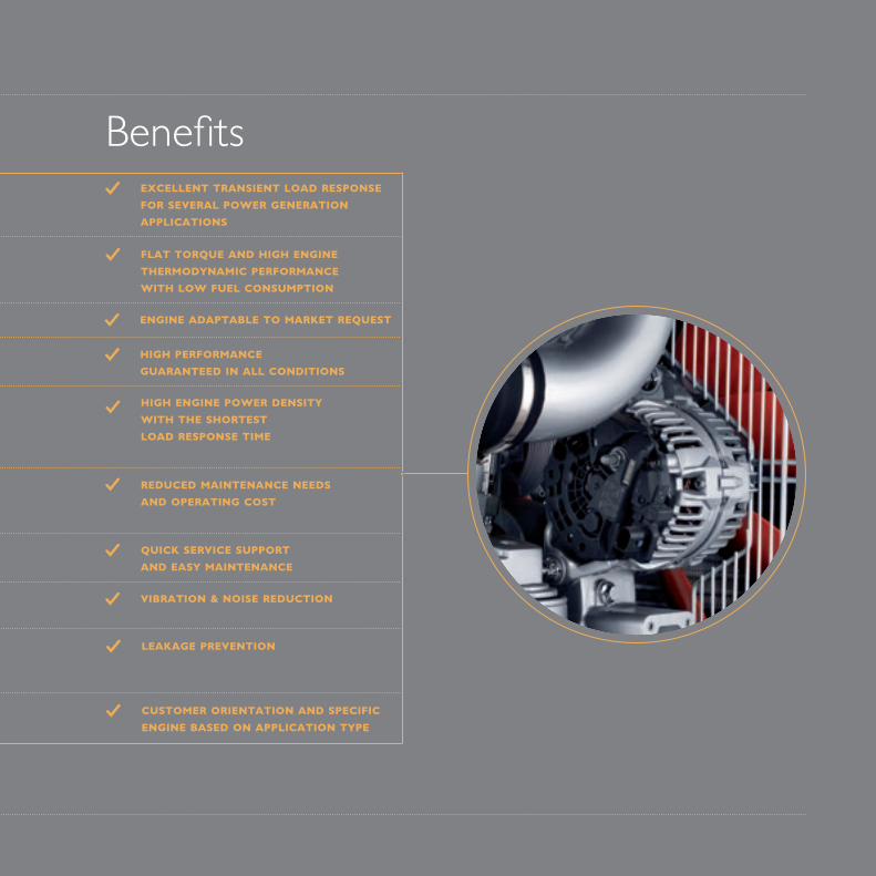
BenefitsEXCELLENT TRANSIENT LOAD RESPONSE FOR SEVERAL POWER GENERATIONAPPLICATIONS
FLAT TORQUE AND HIGH ENGINE THERMODYNAMIC PERFORMANCE WITH LOW FUEL CONSUMPTION
ENGINE ADAPTABLE TO MARKET REQUEST
HIGH PERFORMANCEGUARANTEED IN ALL CONDITIONS
HIGH ENGINE POWER DENSITYWITH THE SHORTESTLOAD RESPONSE TIME
REDUCED MAINTENANCE NEEDSAND OPERATING COST
QUICK SERVICE SUPPORTAND EASY MAINTENANCE
CUSTOMER ORIENTATION AND SPECIFIC ENGINE BASED ON APPLICATION TYPE
LEAKAGE PREVENTION
VIBRATION & NOISE REDUCTION


THE
CU
RSO
R S
ERIE
S
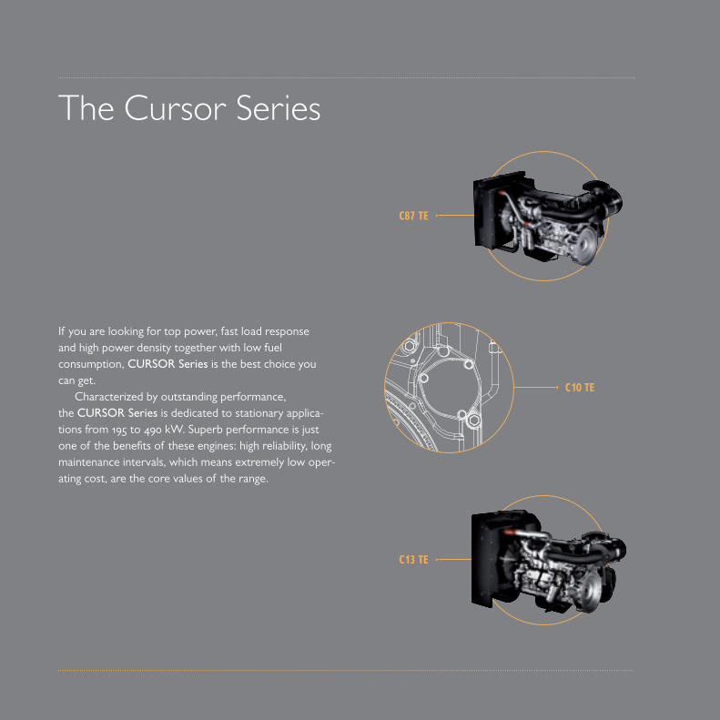
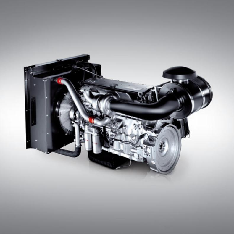
If you are looking for top power, fast load response and high power density together with low fuel consumption, CURSOR Series is the best choice you can get.
Characterized by outstanding performance, the CURSOR Series is dedicated to stationary applica-tions from 195 to 490 kW. Superb performance is just one of the benefits of these engines: high reliability, long maintenance intervals, which means extremely low oper-ating cost, are the core values of the range.
The Cursor Series
C10 TE
C87 TE
C13 TE
LEGEND
STAND-BY POWER OUTPUT [kWm]
PRIMEPOWER OUTPUT [kWm]
1500 RPM 1800 RPM 1500 RPM 1800 RPM
C87 TE3 6L / TAA ECR 8,7 8,7 271 UR 229 249
C87 TE4 6L / TAA ECR 8,7 8,7 333 UR 275 306
C87 TE1D 6L / TAA ECR 8,7 8,7 280 UR1/Tier 3 232 254
C87 TE1F 6L / TAA ECR 8,7 8,7 – Stage IIIA 177 –
C87 TE3F 6L / TAA ECR 8,7 8,7 – Stage IIIA 232 –
C10 TE1D 6L / TAA EUI 10,3 10,3 317 UR1/Tier 3 264 287
C10 TE1F 6L / TAA / I-EGR EUI 10,3 10,3 – Stage IIIA 263 –
CR13 TE6W 6L / TAA ECR 12,9 12,9 454* UR 371* 400*
CR13 TE7W 6L / TAA ECR 12,9 12,9 474 UR 415 428
C13 TE2A 6L / TAA EUI 12,9 12,9 360 UR1 300 327
C13 TE3A 6L / TAA EUI 12,9 12,9 398 UR1 352 360
C13 TE3X 6L / TAA EUI 12,9 12,9 371 Tier 3 – 337
C13 TE1F 6L / TAA / I-EGR EUI 12,9 12,9 – Stage IIIA 296 –
C13 TE2F 6L / TAA / I-EGR EUI 12,9 12,9 – Stage IIIA 342 –
INJEC
TION SY
STEM
DISPLA
CEMEN
T
LITER
S
MODELCY
LINDER
ARRA
NGEMEN
T
AIR IN
TAKE
EXHAU
ST SY
STEM
EMISS
IONS
ARRANGEMENTL In line
AIR INTAKETAA Turbocharged Aftercooler
EXHAUST SYSTEMI-EGR Internal Exhaust Gas Recirculation
INJECTION SYSTEMECR Electronic Common RailEUI Electronic Unit Injector
UR UnregulatedUR1 Previously EU Stage II* Preliminary Data
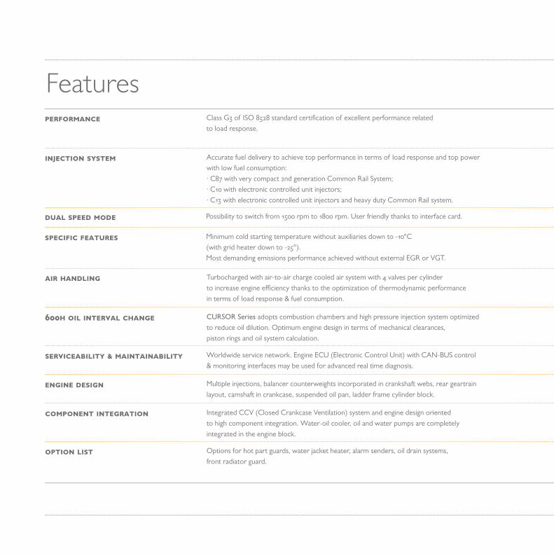
FeaturesClass G3 of ISO 8528 standard certification of excellent performance related to load response.
PERFORMANCE
Accurate fuel delivery to achieve top performance in terms of load response and top power with low fuel consumption: · C87 with very compact 2nd generation Common Rail System; · C10 with electronic controlled unit injectors;· C13 with electronic controlled unit injectors and heavy duty Common Rail system.
INJECTION SYSTEM
Possibility to switch from 1500 rpm to 1800 rpm. User friendly thanks to interface card.DUAL SPEED MODE
Minimum cold starting temperature without auxiliaries down to -10°C(with grid heater down to -25°). Most demanding emissions performance achieved without external EGR or VGT.
SPECIFIC FEATURES
Turbocharged with air-to-air charge cooled air system with 4 valves per cylinderto increase engine efficiency thanks to the optimization of thermodynamic performancein terms of load response & fuel consumption.
AIR HANDLING
CURSOR Series adopts combustion chambers and high pressure injection system optimizedto reduce oil dilution. Optimum engine design in terms of mechanical clearances,piston rings and oil system calculation.
600H OIL INTERVAL CHANGE
Worldwide service network. Engine ECU (Electronic Control Unit) with CAN-BUS control& monitoring interfaces may be used for advanced real time diagnosis.
SERVICEABILITY & MAINTAINABILITY
Multiple injections, balancer counterweights incorporated in crankshaft webs, rear geartrain layout, camshaft in crankcase, suspended oil pan, ladder frame cylinder block.
ENGINE DESIGN
Integrated CCV (Closed Crankcase Ventilation) system and engine design orientedto high component integration. Water-oil cooler, oil and water pumps are completelyintegrated in the engine block.
COMPONENT INTEGRATION
Options for hot part guards, water jacket heater, alarm senders, oil drain systems,front radiator guard.
OPTION LIST
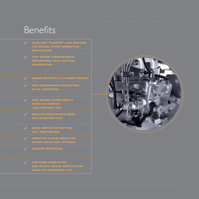
BenefitsEXCELLENT TRANSIENT LOAD RESPONSE FOR SEVERAL POWER GENERATIONAPPLICATIONS
HIGH ENGINE THERMODYNAMICPERFORMANCE WITH LOW FUELCONSUMPTION
ENGINE ADAPTABLE TO MARKET REQUEST
HIGH PERFORMANCE GUARANTEEDIN ALL CONDITIONS
HIGH ENGINE POWER DENSITYWITH THE SHORTESTLOAD RESPONSE TIME
REDUCED MAINTENANCE NEEDSAND OPERATING COST
QUICK SERVICE SUPPORT ANDEASY MAINTENANCE
VIBRATION & NOISE REDUCTIONENGINE STRUCTURAL STIFFNESS
LEAKAGE PREVENTION
CUSTOMER ORIENTATIONAND SPECIFIC ENGINE ARCHITECTURE BASED ON APPLICATION TYPE

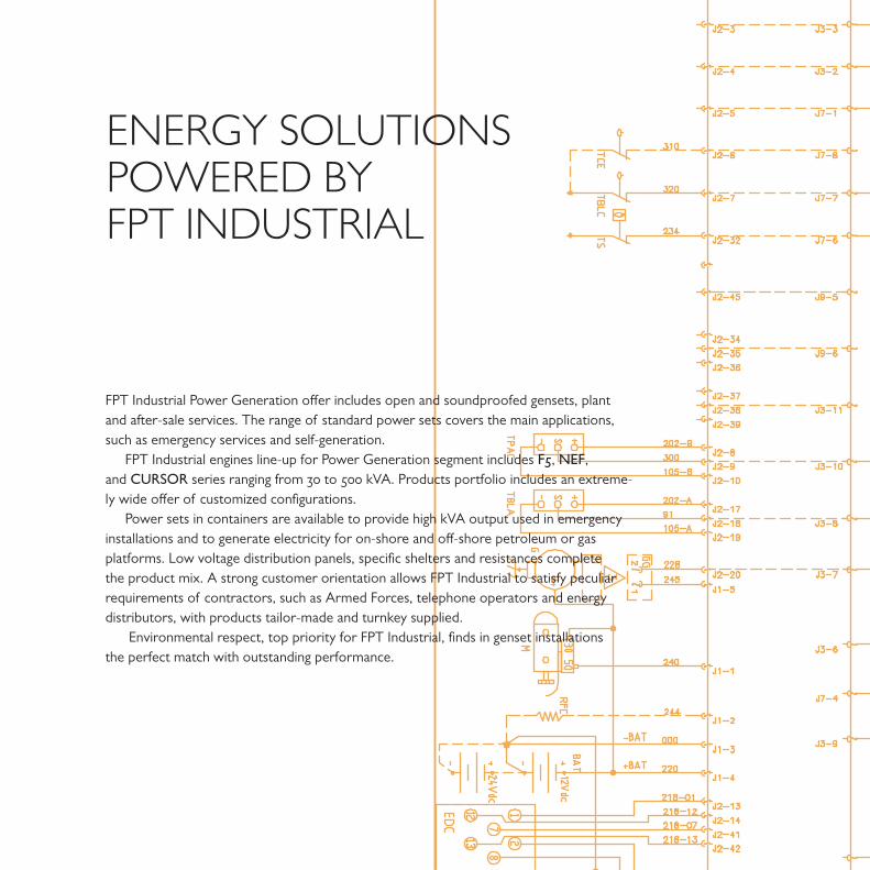
ENERGY SOLUTIONSPOWERED BYFPT INDUSTRIAL
FPT Industrial Power Generation offer includes open and soundproofed gensets, plant and after-sale services. The range of standard power sets covers the main applications, such as emergency services and self-generation.
FPT Industrial engines line-up for Power Generation segment includes F5, NEF, and CURSOR series ranging from 30 to 500 kVA. Products portfolio includes an extreme-ly wide offer of customized configurations.
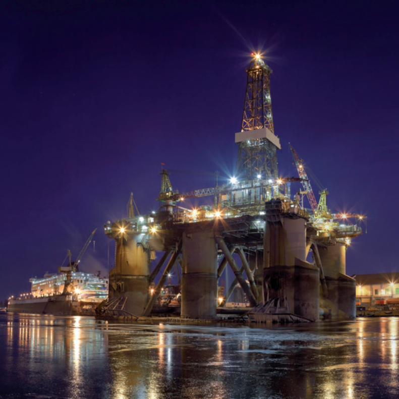
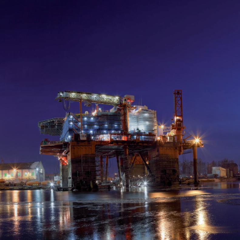
Power sets in containers are available to provide high kVA output used in emergency installations and to generate electricity for on-shore and off-shore petroleum or gas platforms. Low voltage distribution panels, specific shelters and resistances complete the product mix. A strong customer orientation allows FPT Industrial to satisfy peculiar requirements of contractors, such as Armed Forces, telephone operators and energy distributors, with products tailor-made and turnkey supplied.
Environmental respect, top priority for FPT Industrial, finds in genset installations the perfect match with outstanding performance.

OPE
N G
ENSE
TSfr
om 3
0 to
500
kV
A
AIR INTAKENA Naturally AspiratedTC TurbochargedTAA Turbocharged Aftercooler
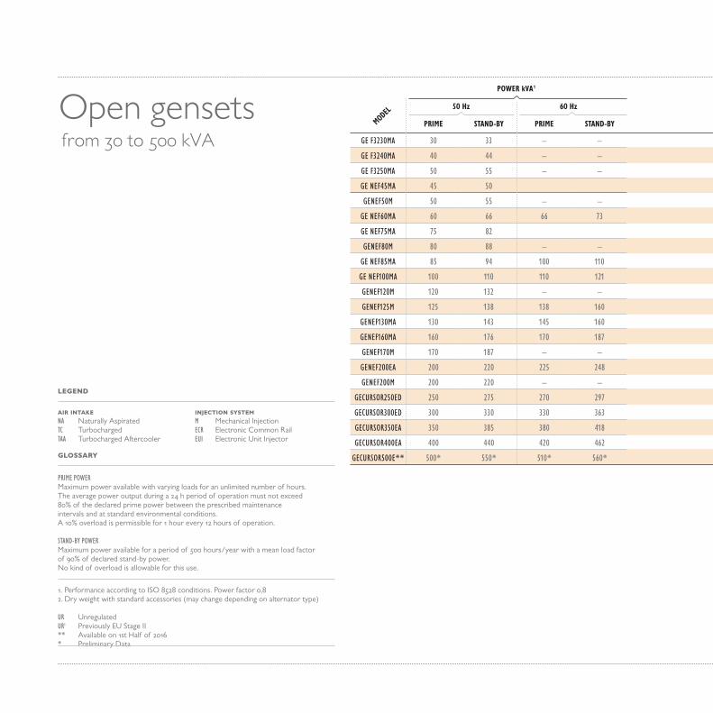
PRIME POWERMaximum power available with varying loads for an unlimited number of hours. The average power output during a 24 h period of operation must not exceed 80% of the declared prime power between the prescribed maintenance intervals and at standard environmental conditions. A 10% overload is permissible for 1 hour every 12 hours of operation.
STAND-BY POWERMaximum power available for a period of 500 hours/year with a mean load factor of 90% of declared stand-by power. No kind of overload is allowable for this use.
1. Performance according to ISO 8528 conditions. Power factor 0,82. Dry weight with standard accessories (may change depending on alternator type)
UR UnregulatedUR1 Previously EU Stage II** Available on 1st Half of 2016* Preliminary Data
LEGEND
GLOSSARY
50 Hz 60 Hz
PRIME STAND-BY PRIME STAND-BY
GE F3230MA 30 33 – –
GE F3240MA 40 44 – –
GE F3250MA 50 55 – –
GE NEF45MA 45 50
GENEF50M 50 55 – –
GE NEF60MA 60 66 66 73
GE NEF75MA 75 82
GENEF80M 80 88 – –
GE NEF85MA 85 94 100 110
GE NEF100MA 100 110 110 121
GENEF120M 120 132 – –
GENEF125M 125 138 138 160
GENEF130MA 130 143 145 160
GENEF160MA 160 176 170 187
GENEF170M 170 187 – –
GENEF200EA 200 220 225 248
GENEF200M 200 220 – –
GECURSOR250ED 250 275 270 297
GECURSOR300ED 300 330 330 363
GECURSOR350EA 350 385 380 418
GECURSOR400EA 400 440 420 462
GECURSOR500E** 500* 550* 510* 560*
MODEL
POWER kVA1
INJECTION SYSTEMM Mechanical InjectionECR Electronic Common RailEUI Electronic Unit Injector
Open gensets from 30 to 500 kVA
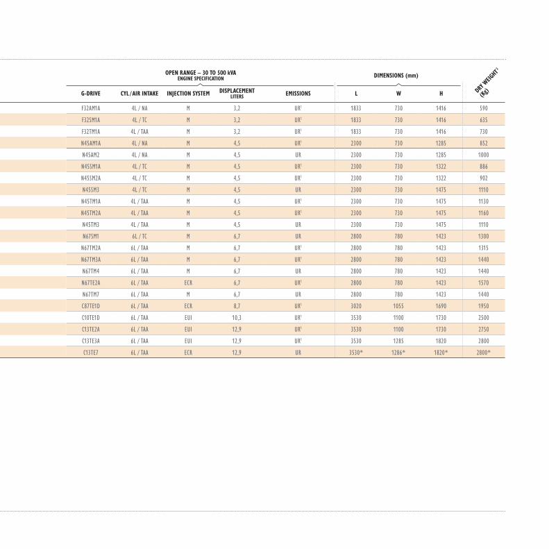
OPEN RANGE – 30 TO 500 kVAENGINE SPECIFICATION DIMENSIONS (mm)
G-DRIVE CYL / AIR INTAKE INJECTION SYSTEM DISPLACEMENT LITERS EMISSIONS L W H
F32AM1A 4L / NA M 3,2 UR1 1833 730 1416 590
F32SM1A 4L / TC M 3,2 UR1 1833 730 1416 635
F32TM1A 4L / TAA M 3,2 UR1 1833 730 1416 730
N45AM1A 4L / NA M 4,5 UR1 2300 730 1285 852
N45AM2 4L / NA M 4,5 UR 2300 730 1285 1000
N45SM1A 4L / TC M 4,5 UR1 2300 730 1322 886
N45SM2A 4L / TC M 4,5 UR1 2300 730 1322 902
N45SM3 4L / TC M 4,5 UR 2300 730 1475 1110
N45TM1A 4L / TAA M 4,5 UR1 2300 730 1475 1130
N45TM2A 4L / TAA M 4,5 UR1 2300 730 1475 1160
N45TM3 4L / TAA M 4,5 UR 2300 730 1475 1110
N67SM1 6L / TC M 6,7 UR 2800 780 1423 1300
N67TM2A 6L / TAA M 6,7 UR1 2800 780 1423 1315
N67TM3A 6L / TAA M 6,7 UR1 2800 780 1423 1440
N67TM4 6L / TAA M 6,7 UR 2800 780 1423 1440
N67TE2A 6L / TAA ECR 6,7 UR1 2800 780 1423 1570
N67TM7 6L / TAA M 6,7 UR 2800 780 1423 1440
C87TE1D 6L / TAA ECR 8,7 UR1 3020 1055 1690 1950
C10TE1D 6L / TAA EUI 10,3 UR1 3530 1100 1730 2500
C13TE2A 6L / TAA EUI 12,9 UR1 3530 1100 1730 2750
C13TE3A 6L / TAA EUI 12,9 UR1 3530 1285 1820 2800
C13TE7 6L / TAA ECR 12,9 UR 3530* 1286* 1820* 2800*
DRY W
EIGHT
2
(Kg)
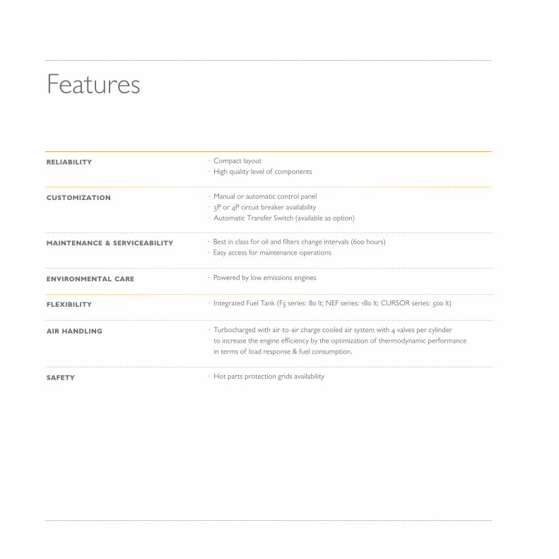
Features
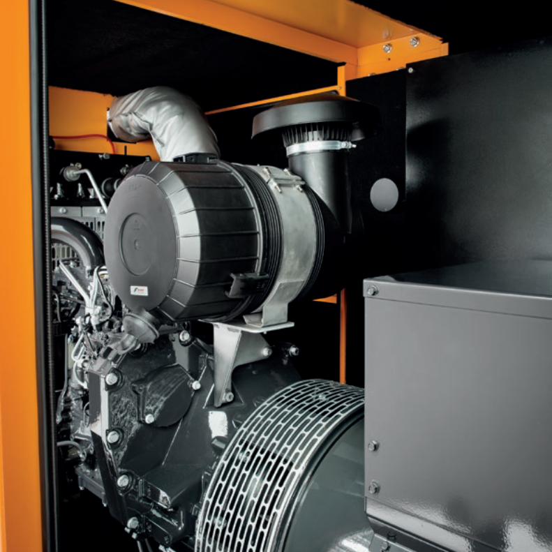
· Compact layout · High quality level of components
RELIABILITY
· Manual or automatic control panel · 3P or 4P circuit breaker availability · Automatic Transfer Switch (available as option)
CUSTOMIZATION
· Best in class for oil and filters change intervals (600 hours) · Easy access for maintenance operations
MAINTENANCE & SERVICEABILITY
· Powered by low emissions enginesENVIRONMENTAL CARE
· Integrated Fuel Tank (F5 series: 80 lt; NEF series: 180 lt; CURSOR series: 500 lt)FLEXIBILITY
· Turbocharged with air-to-air charge cooled air system with 4 valves per cylinder to increase the engine efficiency by the optimization of thermodynamic performance in terms of load response & fuel consumption.
AIR HANDLING
· Hot parts protection grids availabilitySAFETY


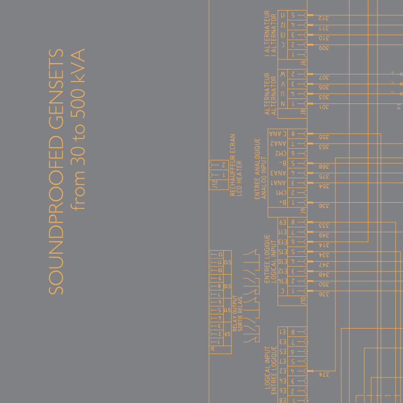
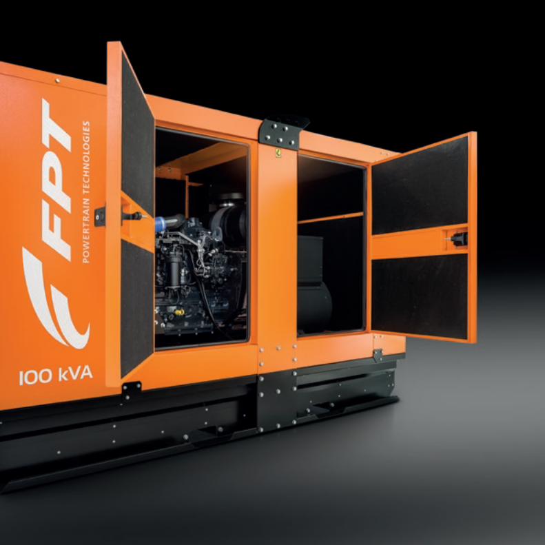
SOU
ND
PRO
OFE
D G
ENSE
TS
from
30
to 5
00 k
VA
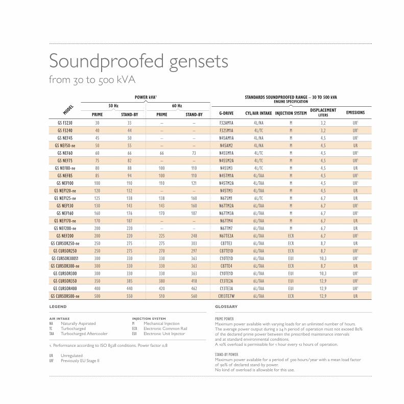
AIR INTAKENA Naturally AspiratedTC TurbochargedTAA Turbocharged Aftercooler
PRIME POWERMaximum power available with varying loads for an unlimited number of hours.The average power output during a 24 h period of operation must not exceed 80% of the declared prime power between the prescribed maintenance intervalsand at standard environmental conditions. A 10% overload is permissible for 1 hour every 12 hours of operation.
STAND-BY POWERMaximum power available for a period of 500 hours/year with a mean load factor of 90% of declared stand-by power. No kind of overload is allowable for this use.
1. Performance according to ISO 8528 conditions. Power factor 0,8
UR UnregulatedUR1 Previously EU Stage II
LEGEND GLOSSARY
INJECTION SYSTEMM Mechanical InjectionECR Electronic Common RailEUI Electronic Unit Injector
Soundproofed gensetsfrom 30 to 500 kVA
50 Hz 60 Hz
STANDARDS SOUNDPROOFED RANGE – 30 TO 500 kVAENGINE SPECIFICATION
PRIME STAND-BY PRIME STAND-BY G-DRIVE CYL/AIR INTAKE INJECTION SYSTEMDISPLACEMENT
LITERSEMISSIONS
GS F3230 30 33 – – F32AM1A 4L/NA M 3,2 UR1
GS F3240 40 44 – – F32SM1A 4L/TC M 3,2 UR1
GS NEF45 45 50 – – N45AM1A 4L/NA M 4,5 UR1
GS NEF50-ne 50 55 – – N45AM2 4L/NA M 4,5 UR
GS NEF60 60 66 66 73 N45SM1A 4L/TC M 4,5 UR1
GS NEF75 75 82 – – N45SM2A 4L/TC M 4,5 UR1
GS NEF80-ne 80 88 100 110 N45SM3 4L/TC M 4,5 UR
GS NEF85 85 94 100 110 N45TM1A 4L/TAA M 4,5 UR1
GS NEF100 100 110 110 121 N45TM2A 4L/TAA M 4,5 UR1
GS NEF120-ne 120 132 – – N45TM3 4L/TAA M 4,5 UR
GS NEF125-ne 125 138 138 160 N67SM1 6L/TC M 6,7 UR
GS NEF130 130 143 143 160 N67TM2A 6L/TAA M 6,7 UR1
GS NEF160 160 176 170 187 N67TM3A 6L/TAA M 6,7 UR1
GS NEF170-ne 170 187 – – N67TM4 6L/TAA M 6,7 UR
GS NEF200-ne 200 220 – – N67TM7 6L/TAA M 6,7 UR
GS NEF200 200 220 225 248 N67TE2A 6L/TAA ECR 6,7 UR1
GS CURSOR250-ne 250 275 275 303 C87TE3 6L/TAA ECR 8,7 UR
GS CURSOR250 250 275 270 297 C87TE1D 6L/TAA ECR 8,7 UR1
GS CURSOR300S1 300 330 330 363 C10TE1D 6L/TAA EUI 10,3 UR1
GS CURSOR300-ne 300 330 330 363 C87TE4 6L/TAA ECR 8,7 UR
GS CURSOR300 300 330 330 363 C10TE1D 6L/TAA EUI 10,3 UR1
GS CURSOR350 350 385 380 418 C13TE2A 6L/TAA EUI 12,9 UR1
GS CURSOR400 400 440 420 462 C13TE3A 6L/TAA EUI 12,9 UR1
GS CURSOR500-ne 500 550 510 560 CR13TE7W 6L/TAA ECR 12,9 UR
MODEL
POWER kVA1
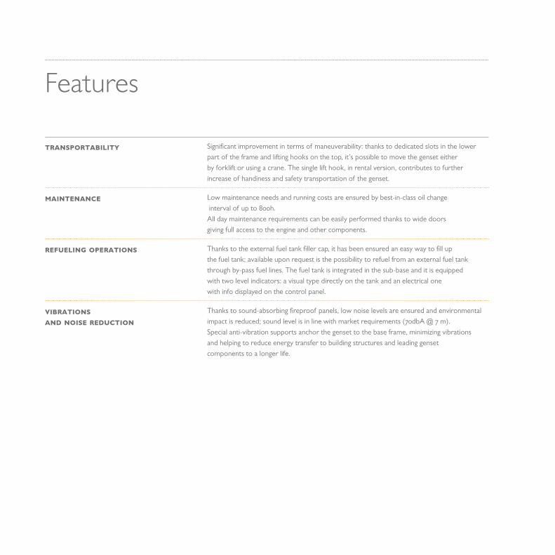
Features
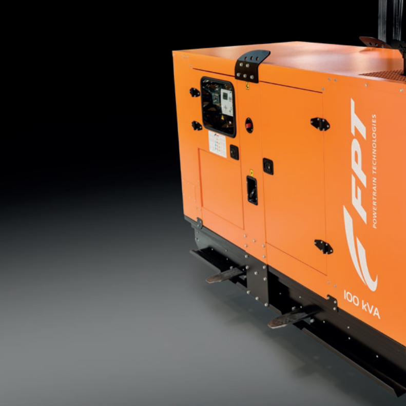
Significant improvement in terms of maneuverability: thanks to dedicated slots in the lower part of the frame and lifting hooks on the top, it’s possible to move the genset either by forklift or using a crane. The single lift hook, in rental version, contributes to further increase of handiness and safety transportation of the genset.
Low maintenance needs and running costs are ensured by best-in-class oil change interval of up to 800h. All day maintenance requirements can be easily performed thanks to wide doors giving full access to the engine and other components.
Thanks to the external fuel tank filler cap, it has been ensured an easy way to fill up the fuel tank; available upon request is the possibility to refuel from an external fuel tank through by-pass fuel lines. The fuel tank is integrated in the sub-base and it is equipped with two level indicators: a visual type directly on the tank and an electrical one with info displayed on the control panel.
Thanks to sound-absorbing fireproof panels, low noise levels are ensured and environmental impact is reduced; sound level is in line with market requirements (70dbA @ 7 m).Special anti-vibration supports anchor the genset to the base frame, minimizing vibrations and helping to reduce energy transfer to building structures and leading genset components to a longer life.
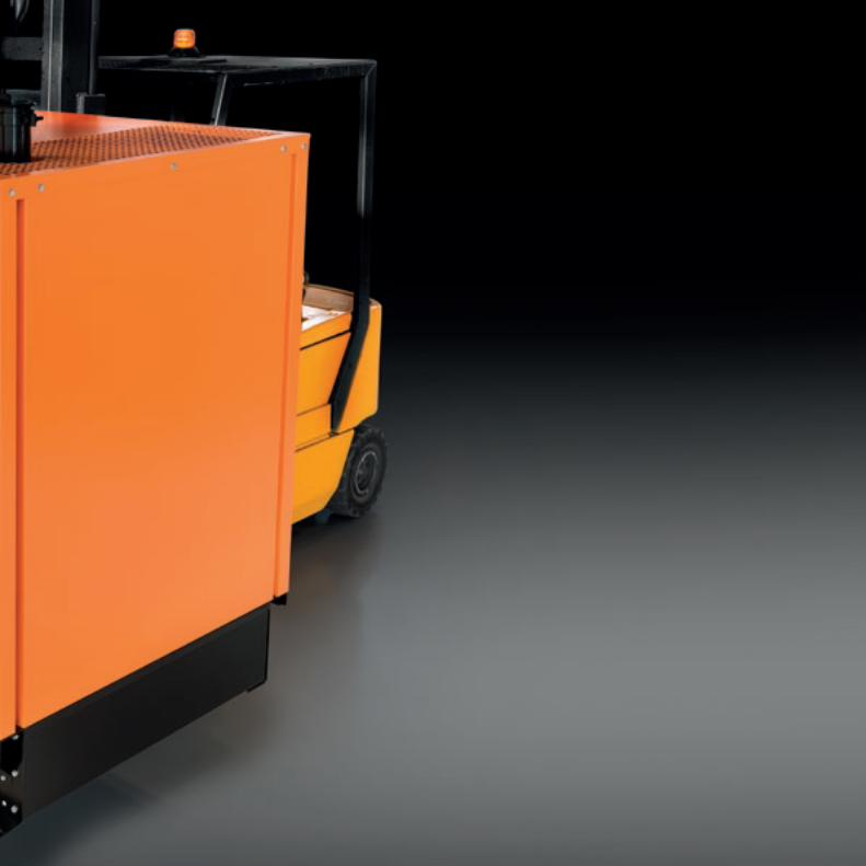
TRANSPORTABILITY
MAINTENANCE
REFUELING OPERATIONS
VIBRATIONS AND NOISE REDUCTION


MRS72 Manual Control Panel with Remote Start
• Start up and shut down keys through an external signal;• Engine and alternator parameters monitoring;• “Manual” and “Super-manual” operational modes;• Storage of last 250 events;• Multilingual diagnostic software (Italian, English, French and Spanish);• PC and/or on site (through optical key) programming;• Battery charger to ensure correct battery efficiency and command/control system alimentation (optional).
START
ENGINE STATUS
!
MRS72 | Remote Start Manual Controller
OK
STOP
TTEST
AAU
TO
MMAN
Optical Interface
XOFF
GEN
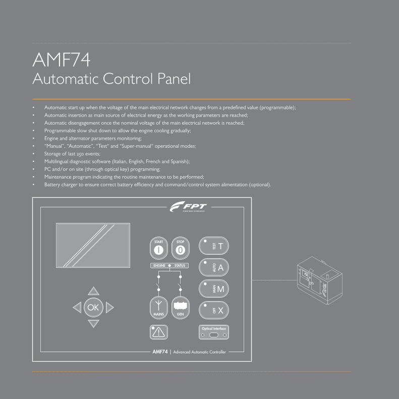
• Automatic start up when the voltage of the main electrical network changes from a predefined value (programmable);• Automatic insertion as main source of electrical energy as the working parameters are reached;• Automatic disengagement once the nominal voltage of the main electrical network is reached;• Programmable slow shut down to allow the engine cooling gradually;• Engine and alternator parameters monitoring;• “Manual”, “Automatic”, “Test“ and “Super-manual“ operational modes;• Storage of last 250 events;• Multilingual diagnostic software (Italian, English, French and Spanish);• PC and/or on site (through optical key) programming;• Maintenance program indicating the routine maintenance to be performed;• Battery charger to ensure correct battery efficiency and command/control system alimentation (optional).
AMF74 Automatic Control Panel
START
ENGINE STATUS
!
MAINS
AMF74 | Advanced Automatic Controller
OK
STOP
TTEST
AAU
TO
MMAN
Optical Interface
XOFF
GEN


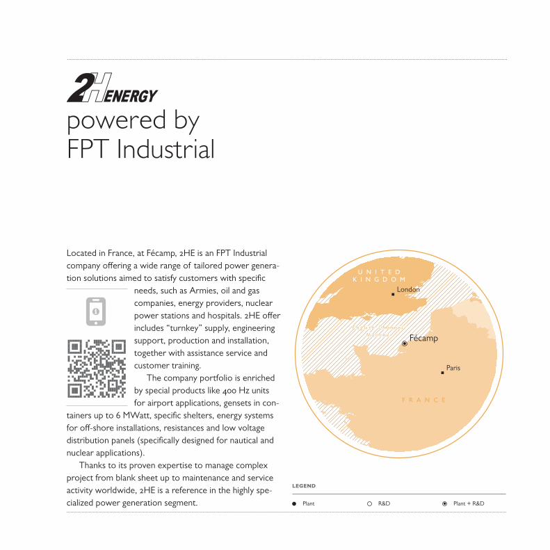
Located in France, at Fécamp, 2HE is an FPT Industrial company offering a wide range of tailored power genera-tion solutions aimed to satisfy customers with specific
needs, such as Armies, oil and gas companies, energy providers, nuclear power stations and hospitals. 2HE offer includes “turnkey” supply, engineering support, production and installation, together with assistance service and customer training.
The company portfolio is enriched by special products like 400 Hz units for airport applications, gensets in con-
tainers up to 6 MWatt, specific shelters, energy systems for off-shore installations, resistances and low voltage distribution panels (specifically designed for nautical and nuclear applications).
Thanks to its proven expertise to manage complex project from blank sheet up to maintenance and service activity worldwide, 2HE is a reference in the highly spe-cialized power generation segment.
Fécamp
Paris
London
f r a n c e
U n i t e d K i n g d o m
E n g l i s h C h a n n e lM a n c h e
powered byFPT Industrial
Plant Plant + R&DR&D
LEGEND


Graphic Design STAR Srl, Italy
All the pictures, drawings illustrations and descriptions contained in this brochure are based on product information available to FPT Industrial at the time of printing (31/01/2016).Some of the engine line-ups may refer to a specific market configuration which may not be present or offered for sale available in all other markets. The colors featured in this brochure may differ from the originals.FPT Industrial reserves the right to introduce any modifications, at any time and without any prior advance notice, to design, material, components equipment and/or technical specifications.

FPT INDUSTRIAL S.p.A.Via Puglia 15, 10156 – Torino, [email protected]