Embed Size (px)
Citation preview
Power Flow Redistribution in Croatian Power System Network using Phase-
Shifting Transformer
Ivica Pavić
Faculty of Electrical Engineering and Computing
Zagreb, CROATIA
Sejid Tešnjak
Faculty of Electrical Engineering and Computing
Zagreb, CROATIA
Tomislav Špoljarić
Technical Polytechnic in Zagreb, CROATIA
1. Introduction
Transformer, observed as an element of the power system, is usually used to transport electric
power between two different voltage levels. One of these voltage leves can be regulated by
magnitude, and this method of regulation is called voltage magnitude regulation. Besides the
voltage magnitude, the voltage phase angle can be regulated. This method of regulation is
called phase angle regulation, and is used when there is a need for regulating not only the
voltage magnitude, but also the phase angle between two different voltage levels.
Transformers, who have the ability to control the phase angle between primary and secondary
side are called phase-shifting transformers (PST). By using voltage magitude regulation, the
reactive power flows can be controled. However, phase angle regulation can be used if the
active power flows are to be controlled.
Electricity market deregulation has given a significant role to PST's. PST, as an element of a
power system, can be used to control power flows, therefore the power system containing
such elements can provide its maximum efficiency. The use of PST's in the power system can
also solve major problems that come together with deregulation of electric market, like power
transit or uneven loading. The transmission network is used to transport power from producer
to consumer, who have a concealed contract in which is stated that producer produces a
certain amount of electrical energy and consumer buys this energy. Hence, the contractual
path of the electricity is straight from producer to consumer. However, the physical path is a
group of parallel paths, some of which lead through regions (countries) that are not involved
in the contract. In a situation like this, uncontrolled power flows can occur in the transmission
system of a region involved in the contract and overload its lines, when regions or paths not
involved, are to be avoided. As for the uneven loading, it is necessary to state that the
distribution of the power flow between two parallel lines is dictated by their impedances. The
line with the smallest reactance carries the largest part of the load. In most situations, one of
the two lines will be operating well below its nominal rating because otherwise the parallel
line would be overloaded. Solution to problems like these is using the active power control.
This is where the PST's have a significant role, because a phase angle regulation can be used
to redirect active power flows and manage the loading of transmission paths, thus the losses in
transmission network are minimal and the efficiency of such network is enhanced.
2. Voltage phase angle regulation
2.1. Principles od phase angle regulation
Active power flow along a transmission line or transformer is determined mainly by the angle
difference of the terminal voltages. It is also inversely proportional to the transmission line or
transformer reactance which is placed between these two sides. Controling of active power
flows can be made mainly by changing voltage phase angles and line reactances. Altering the
voltage magnitudes affects significantly the reactive power flows and therefore it is not
effective for active power flow control. Reactance can be altered by placing a series capacitor
along the line to compensate the inductance of the line. Besides increased power flow,
switching the capacitors at an appropriate time can be used to dampen oscillations. Flexible
alternating current transmission systems (FACTS devices) can be used to alter the total line
reactance very dinamically.
The most common used method for effective active power flow control is a change of voltage
phase angles. Because of their proportionality, the active power flow through the transmission
line can be increased by adding the angle shift to the existing phase angle. This angle shift is
controllable within certain limits. According to the angle between phase and adding voltage
there are two types of phase angle regulation:
phase angle and voltage magnitude regulation – an angle between phase and
adding voltage varies between 0 and 90 degrees
phase angle regulation only – an angle between voltages is 90 degrees
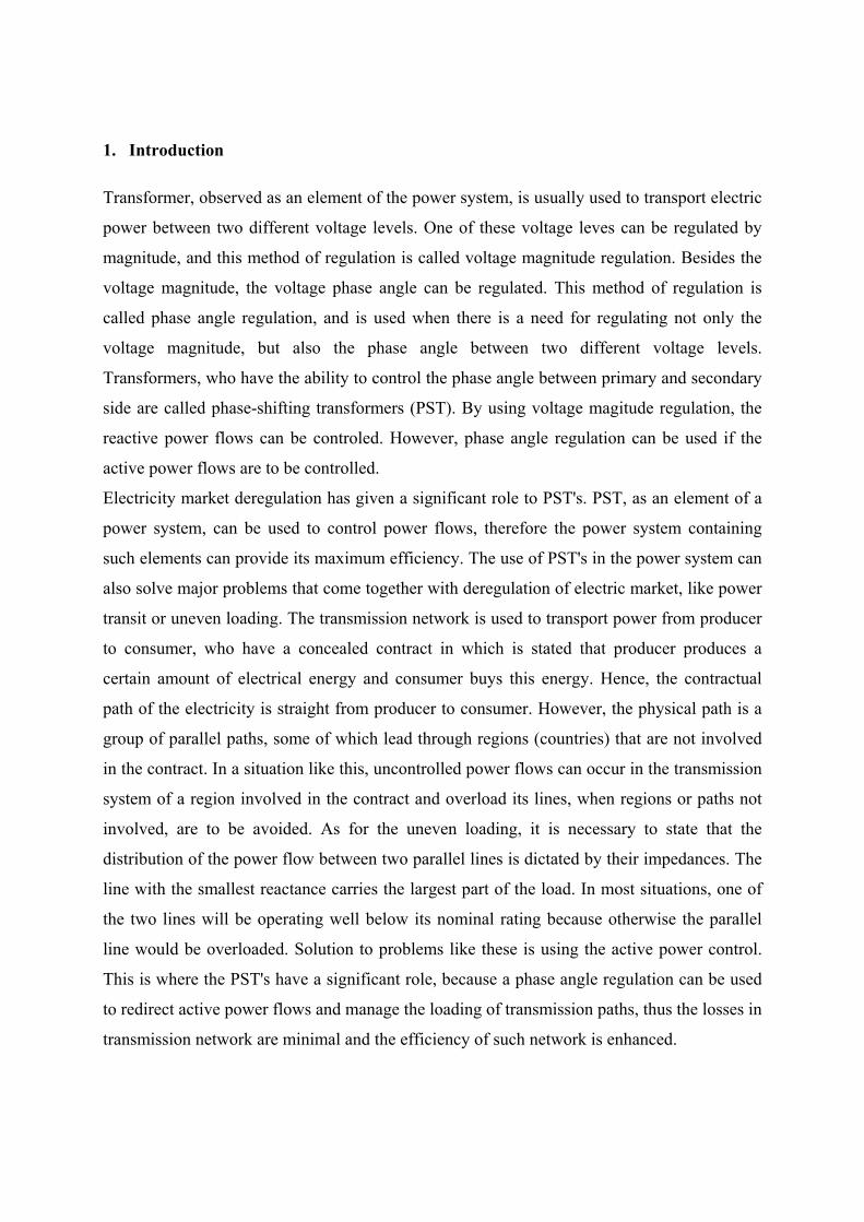
Principles of both types of phase angle regulation, along with voltage magnitude regulation
are shown in fig. 2.1.
Figure 2.1. Basic principles of regulation: a) voltage magnitude regulation; b) phase angle and
voltage magnitude regulation; c) phase angle regulation only
When a phase angle and voltage magnitude regulation is used, not only does a phase angle of
a secondary voltage alter in comparison to the primary side, but there is an altering in
magnitude of secondary voltage compared to the primary voltage also. This type of regulation
can be obtained by connecting the end of one regulation winding in a series with previous
phase, i.e. phase C voltage is added to the phase A voltage, as shown in fig. 2.1.
Second type of phase angle regulation (phase angle regulation only) is a method of regulating
the phase angle shift of a secondary voltage, where magnitudes of both voltages are equal.
2.2. Mathematical modelling of PST
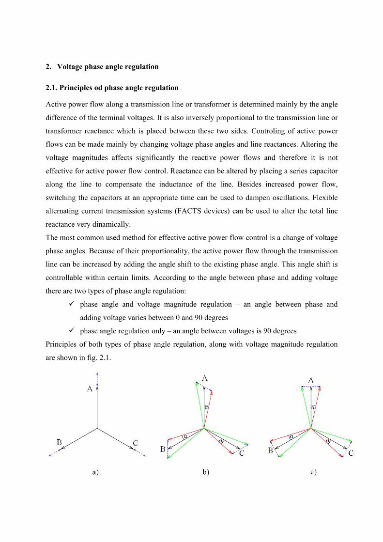
A per-unit model of ideal transformer with tap changing is used to describe the phase angle
regulation [1]. This model is shown in fig. 2.2.
Figure 2.2. Basic equivalent circuit of a PST for coupling between primary and secondary
coils with both primary and secondary off-nominal turns ratio of and , in p.u.
To describe the phase shift, the model of a transformer has to be provided with a complex
turns ratio. Besides, the invariance of the product representing the apparent power across
the ideal transformer requires the distinction to be made between the turns ratio for current
and voltage:
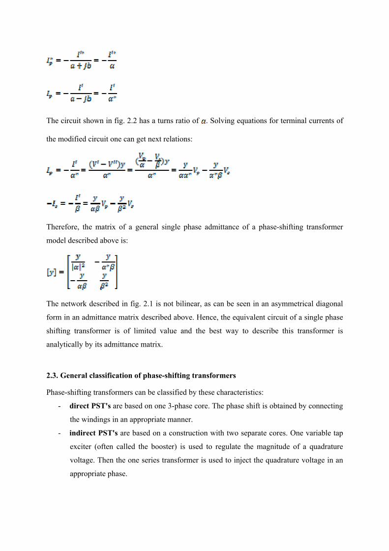
The circuit shown in fig. 2.2 has a turns ratio of . Solving equations for terminal currents of
the modified circuit one can get next relations:
Therefore, the matrix of a general single phase admittance of a phase-shifting transformer
model described above is:
The network described in fig. 2.1 is not bilinear, as can be seen in an asymmetrical diagonal
form in an admittance matrix described above. Hence, the equivalent circuit of a single phase
shifting transformer is of limited value and the best way to describe this transformer is
analytically by its admittance matrix.
2.3. General classification of phase-shifting transformers
Phase-shifting transformers can be classified by these characteristics:
- direct PST's are based on one 3-phase core. The phase shift is obtained by connecting
the windings in an appropriate manner.
- indirect PST's are based on a construction with two separate cores. One variable tap
exciter (often called the booster) is used to regulate the magnitude of a quadrature
voltage. Then the one series transformer is used to inject the quadrature voltage in an
appropriate phase.

- asymmetrical PST's create an output voltage with altered phase and magnitude in
comparison with an input voltage.
- symmetrical PST's create an output voltage with altered phase compared to the input
voltage. The magnitude of an output voltage remains unaltered.
The combination of the first two types with the two last types described above results in 4
ain categories of PST's: direct asymmetrical, direct symmetrical, indirect asymmetrical and
indirect symmetrical PST's [2,3].
m
3. Phase angle regulation in Croatian power system
Because of the role of electricity trade and transit between Southeast and Western Europe, a
need for a phase angle regulation in Croatian power system appeared. A results of preliminary
analysis have shown that the small change in phase angle has a significant impact on power
flow between 400, 220 and 110 kV levels and, depending on a shift, energy exchange is
expected in both directions. A PST was installed in TS Žerjavinec, where the operation of a
phase angle regulation was expected to be most effective in satisfying the needs for
controlling the trade and transit. Main task for this PST is controlling and redirecting power
flows on 400, 220 and 110 kV voltage levels.
Selection of a PST in TS Žerjavinec included observing the needs and thus searching for a
most economical solution, not requiring significant increase in investment and spatial projects
changing. 400 MVA autotransformer, with the ratio of transformation 400/231 kV and the
possibility to alter both magnitude and phase angle, was selected. Voltage magnitude or phase
angle regulation can be selected in the unloaded condition only.
For the turns ratio lesser than two, it is better to choose the autotransformer [4]. It is easier,
cheaper and has less losses. From the perspective of efficiency and investment, it has more
advantages than two-winding transformer. The type of phase angle regulation was on-load tap
changing with three-phase tap changer, where regulating winding has 25 possible tap
positions with the regulation step of 16 bends, having overall 192 bends and is made in
neutral point. Made in this way, a PST has a wanted impact on both HV and LV levels of the
trasformer. However, this type of phase angle regulation is nonlinear, and regulation range is
asymmetric, varying from -4.48° (negative phase angle shift) to +6.76° (positive phase angle
shift) in the loaded condition. Voltage magnitude regulation selected for this transformer is
also on-load tap changing, because of its flexibility and efficiency. For the possibility of
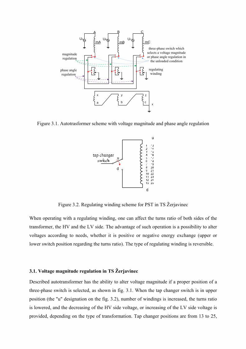
adjusting both levels, a regulation in neutral point is selected. Autotransformer scheme is
shown in fig. 3.1, and regulating winding is shown in fig. 3.2. By changing the position of
three-phase switch shown in fig. 3.1 in the unloaded condition phase angle regulation can be
selected instead of a voltage magnitude regulation.
UA UCUB
mA mB mC
A B C
regulating winding
three-phase switch which selects a voltage magnitude or phase angle regulation in
the unloaded condition
x
c
z
b
y
ax
magnitude regulation
phase angle regulation
Figure 3.1. Autotrasformer scheme with voltage magnitude and phase angle regulation
Figure 3.2. Regulating winding scheme for PST in TS Žerjavinec
When operating with a regulating winding, one can affect the turns ratio of both sides of the
transformer, the HV and the LV side. The advantage of such operation is a possibility to alter
voltages according to needs, whether it is positive or negative energy exchange (upper or
lower switch position regarding the turns ratio). The type of regulating winding is reversible.
3.1. Voltage magnitude regulation in TS Žerjavinec
Described autotransformer has the ability to alter voltage magnitude if a proper position of a
three-phase switch is selected, as shown in fig. 3.1. When the tap changer switch is in upper
position (the "u" designation on the fig. 3.2), number of windings is increased, the turns ratio
is lowered, and the decreasing of the HV side voltage, or increasing of the LV side voltage is
provided, depending on the type of transformation. Tap changer positions are from 13 to 25,
respectively, as shown in fig. 3.2. If the tap changer switch is in lower position, number of
windings is decreased, the turns ratio is increased, thus the increasing of the HV side voltage,
or decreasing of the LV side voltage is provided. Tap changer positions are from 1 to 13,
respectively, as shown in fig. 3.2. According to this, positions 1 and 25 are ending positions,
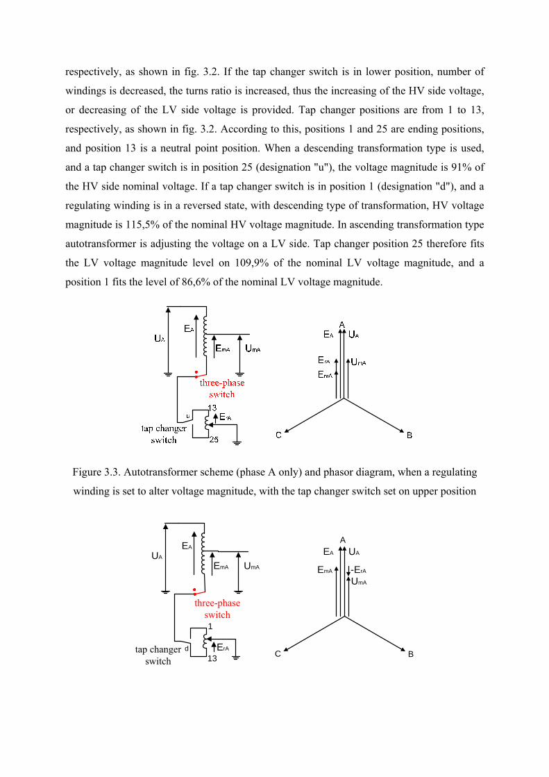
and position 13 is a neutral point position. When a descending transformation type is used,
and a tap changer switch is in position 25 (designation "u"), the voltage magnitude is 91% of
the HV side nominal voltage. If a tap changer switch is in position 1 (designation "d"), and a
regulating winding is in a reversed state, with descending type of transformation, HV voltage
magnitude is 115,5% of the nominal HV voltage magnitude. In ascending transformation type
autotransformer is adjusting the voltage on a LV side. Tap changer position 25 therefore fits
the LV voltage magnitude level on 109,9% of the nominal LV voltage magnitude, and a
position 1 fits the level of 86,6% of the nominal LV voltage magnitude.
Figure 3.3. Autotransformer scheme (phase A only) and phasor diagram, when a regulating
winding is set to alter voltage magnitude, with the tap changer switch set on upper position
UA
UmAEmA
EA
three-phase switch
ErA
1
13
A
UA
UmA
EA
EmA
BCd
-ErA
tap changer switch
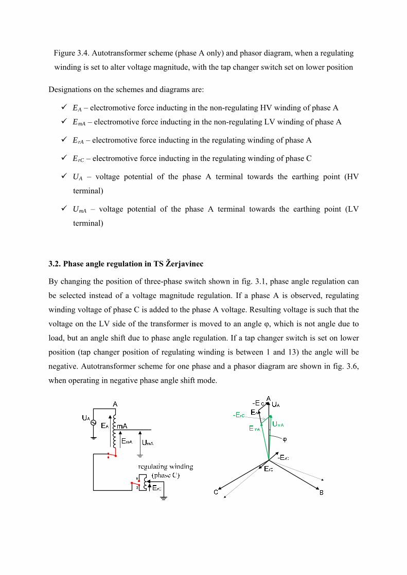
Figure 3.4. Autotransformer scheme (phase A only) and phasor diagram, when a regulating
winding is set to alter voltage magnitude, with the tap changer switch set on lower position
Designations on the schemes and diagrams are:
EA – electromotive force inducting in the non-regulating HV winding of phase A
EmA – electromotive force inducting in the non-regulating LV winding of phase A
ErA – electromotive force inducting in the regulating winding of phase A
ErC – electromotive force inducting in the regulating winding of phase C
UA – voltage potential of the phase A terminal towards the earthing point (HV
terminal)
UmA – voltage potential of the phase A terminal towards the earthing point (LV
terminal)
3.2. Phase angle regulation in TS Žerjavinec
By changing the position of three-phase switch shown in fig. 3.1, phase angle regulation can
be selected instead of a voltage magnitude regulation. If a phase A is observed, regulating
winding voltage of phase C is added to the phase A voltage. Resulting voltage is such that the
voltage on the LV side of the transformer is moved to an angle φ, which is not angle due to
load, but an angle shift due to phase angle regulation. If a tap changer switch is set on lower
position (tap changer position of regulating winding is between 1 and 13) the angle will be
negative. Autotransformer scheme for one phase and a phasor diagram are shown in fig. 3.6,
when operating in negative phase angle shift mode.
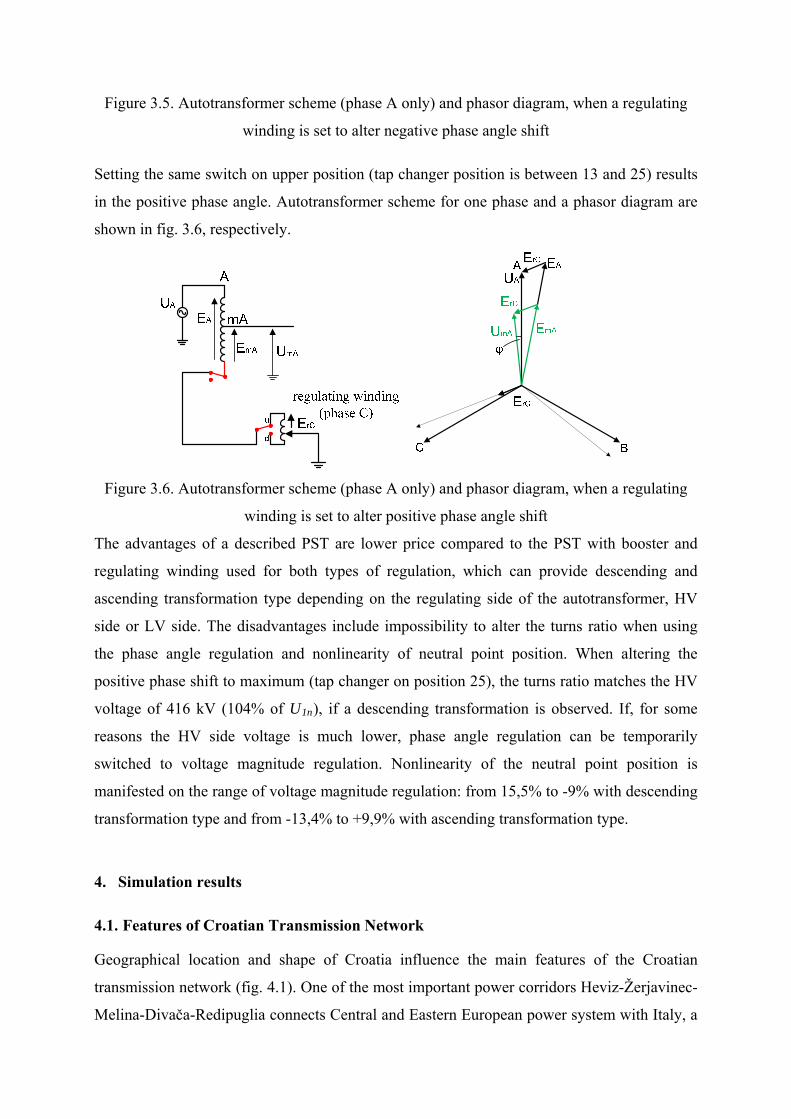
Figure 3.5. Autotransformer scheme (phase A only) and phasor diagram, when a regulating
winding is set to alter negative phase angle shift
Setting the same switch on upper position (tap changer position is between 13 and 25) results
in the positive phase angle. Autotransformer scheme for one phase and a phasor diagram are
shown in fig. 3.6, respectively.
Figure 3.6. Autotransformer scheme (phase A only) and phasor diagram, when a regulating
winding is set to alter positive phase angle shift
The advantages of a described PST are lower price compared to the PST with booster and
regulating winding used for both types of regulation, which can provide descending and
ascending transformation type depending on the regulating side of the autotransformer, HV
side or LV side. The disadvantages include impossibility to alter the turns ratio when using
the phase angle regulation and nonlinearity of neutral point position. When altering the
positive phase shift to maximum (tap changer on position 25), the turns ratio matches the HV
voltage of 416 kV (104% of U1n), if a descending transformation is observed. If, for some
reasons the HV side voltage is much lower, phase angle regulation can be temporarily
switched to voltage magnitude regulation. Nonlinearity of the neutral point position is
manifested on the range of voltage magnitude regulation: from 15,5% to -9% with descending
transformation type and from -13,4% to +9,9% with ascending transformation type.
4. Simulation results
4.1. Features of Croatian Transmission Network
Geographical location and shape of Croatia influence the main features of the Croatian
transmission network (fig. 4.1). One of the most important power corridors Heviz-Žerjavinec-
Melina-Divača-Redipuglia connects Central and Eastern European power system with Italy, a
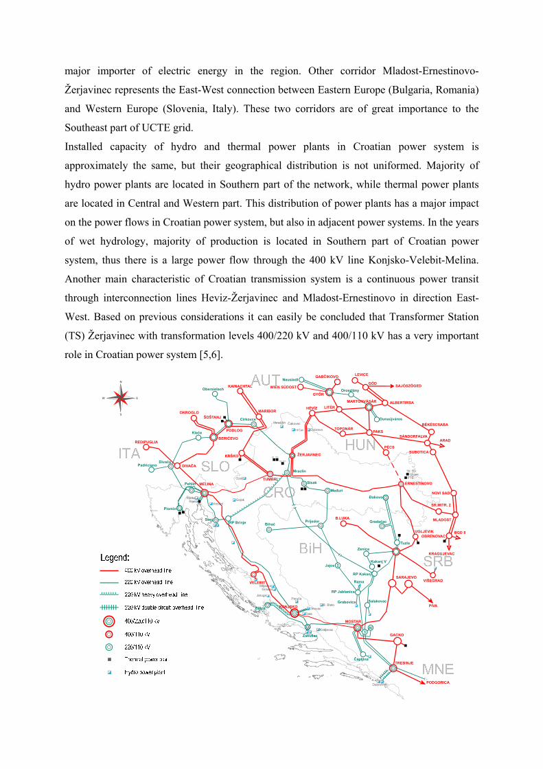
major importer of electric energy in the region. Other corridor Mladost-Ernestinovo-
Žerjavinec represents the East-West connection between Eastern Europe (Bulgaria, Romania)
and Western Europe (Slovenia, Italy). These two corridors are of great importance to the
Southeast part of UCTE grid.
Installed capacity of hydro and thermal power plants in Croatian power system is
approximately the same, but their geographical distribution is not uniformed. Majority of
hydro power plants are located in Southern part of the network, while thermal power plants
are located in Central and Western part. This distribution of power plants has a major impact
on the power flows in Croatian power system, but also in adjacent power systems. In the years
of wet hydrology, majority of production is located in Southern part of Croatian power
system, thus there is a large power flow through the 400 kV line Konjsko-Velebit-Melina.
Another main characteristic of Croatian transmission system is a continuous power transit
through interconnection lines Heviz-Žerjavinec and Mladost-Ernestinovo in direction East-
West. Based on previous considerations it can easily be concluded that Transformer Station
(TS) Žerjavinec with transformation levels 400/220 kV and 400/110 kV has a very important
role in Croatian power system [5,6].
Figure 4.1. 400 kV and 220 kV transmission network of Croatian and adjacent power systems
4.2. Numerical examples
Effect of phase-shifting transformer 400/220 kV installed in TS Žerjavinec was analyzed for a
real situation in Croatian power system as it was this winter. The total consumption of
Croatian power system was in that case 2850 MW, which is very close to the maximum load
of about 3100 MW. The own production was 2150 MW and the rest (about 760 MW) has
been imported from Eastern Europe through Hungary, Serbia and Bosnia and Herzegovina.
The difference between total consumption and production with imports was the power losses
in Croatian network (about 60 MW). In the observed case, the transit from Southeast Europe
to Italy, which closes over the Croatian transmission network was about 600 MW. For the
analysis of power flows and the impact of voltage angle regulation in TS Žerjavinec, the
entire Croatian power system and 400 kV and 220 kV parts of adjacent power systems were
modeled.
The active power flows of the network in the immediate vicinity of TS Žerjavinec are shown
in fig. 4.2. In this case, phase-shifting transformer was used for voltage magnitude regulation
and its tap changer was in the middle position (13), which means the nominal turns ratio. This
initial case, which is the basis for all further analysis is marked as Case 0.
In order to determine the impact of voltage angle control, the transformer is transferred in
voltage phase angle regulation mode and its tap changer is set at the upper end position (25)
which corresponds to a positive angle of the 6.76° in unloaded condition. This variant is
marked as Case 1 and the results of load flow calculation are shown in fig. 4.3. In the Case 2
the transformer tap changer is set at the lower end position (1) which corresponds to a
negative angle of the 4.48° in unloaded condition and results are shown in fig. 4.4.
From the given results it can be concluded that changing of transformer’s turns ratio
redistributes active power flows between 400 kV network and 220 kV and 110 kV network.
In the Case 1, when tap changer is set at the upper end position, active power flow through
phase-shifting transformer is increased for about 140 MW in direction from 400 kV bus to
220 kV bus, compared to the Case 0. Unlike the previous case, in the Case 2, when tap
changer is set at the lower end position active power flow through phase-shifting transformer
from 400 kV bus to 220 kV bus is decreased for about 100 MW compared to the Case 0.
Based on the obtained results, it can be concluded that the voltage angle change of 1° in the
unloaded condition causes a change of active power flow through the phase-shifting
transformer to approximately 20 MW.
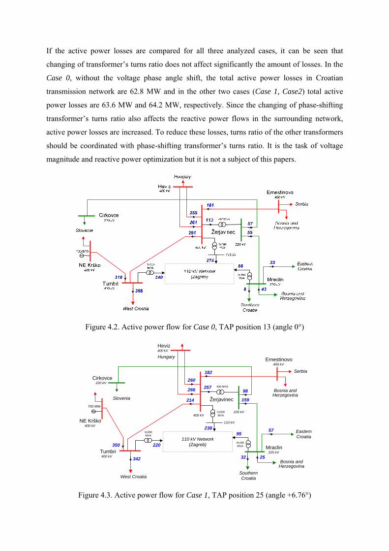
If the active power losses are compared for all three analyzed cases, it can be seen that
changing of transformer’s turns ratio does not affect significantly the amount of losses. In the
Case 0, without the voltage phase angle shift, the total active power losses in Croatian
transmission network are 62.8 MW and in the other two cases (Case 1, Case2) total active
power losses are 63.6 MW and 64.2 MW, respectively. Since the changing of phase-shifting
transformer’s turns ratio also affects the reactive power flows in the surrounding network,
active power losses are increased. To reduce these losses, turns ratio of the other transformers
should be coordinated with phase-shifting transformer’s turns ratio. It is the task of voltage
magnitude and reactive power optimization but it is not a subject of this papers.
Figure 4.2. Active power flow for Case 0, TAP position 13 (angle 0°)
Žerjavinec
Heviz
Ernestinovo
Mraclin
Bosnia and Herzegovina
NE Krško
Cirkovce
Tumbri
182
214
266 257
95238
350
342
220
159
98
32 25
57
260400 MVA
110 kV Network (Zagreb)
SouthernCroatiaWest Croatia
700 MW
Slovenia
EasternCroatia
Bosnia and Herzegovina
Serbia
Hungary
2x300MVA400 kV
400 kV
400 kV
400 kV
400 kV
220 kV
220 kV
220 kV
3x300MVA
110 kV
3x150MVA
Figure 4.3. Active power flow for Case 1, TAP position 25 (angle +6.76°)
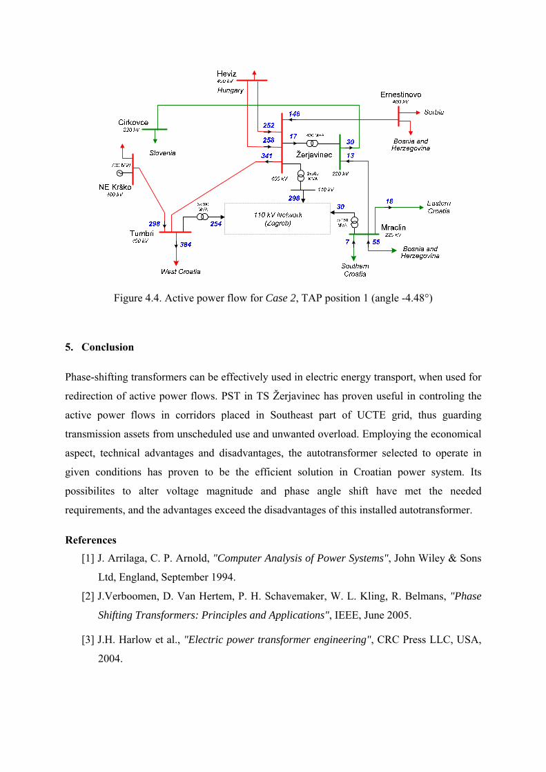
Figure 4.4. Active power flow for Case 2, TAP position 1 (angle -4.48°)
5. Conclusion
Phase-shifting transformers can be effectively used in electric energy transport, when used for
redirection of active power flows. PST in TS Žerjavinec has proven useful in controling the
active power flows in corridors placed in Southeast part of UCTE grid, thus guarding
transmission assets from unscheduled use and unwanted overload. Employing the economical
aspect, technical advantages and disadvantages, the autotransformer selected to operate in
given conditions has proven to be the efficient solution in Croatian power system. Its
possibilites to alter voltage magnitude and phase angle shift have met the needed
requirements, and the advantages exceed the disadvantages of this installed autotransformer.
References
[1] J. Arrilaga, C. P. Arnold, "Computer Analysis of Power Systems", John Wiley & Sons
Ltd, England, September 1994.
[2] J.Verboomen, D. Van Hertem, P. H. Schavemaker, W. L. Kling, R. Belmans, "Phase
Shifting Transformers: Principles and Applications", IEEE, June 2005.
[3] J.H. Harlow et al., "Electric power transformer engineering", CRC Press LLC, USA,
2004.

[4] T. Kelemen, B. Ćućić, "Three-phase autotransformer 400 MVA, 400/231/(10,5) kV
with voltage regulation in neutral point for TS Žerjavinec", Končar - Electrical
Engineering Institute, Zagreb, February 2003.
[5] S. Tešnjak, I. Pavić, "Load flow calculation with phase-shifting transformer 400/220
kV in TS Žerjavinec", FER, Zagreb, March 2003.
[6] G. Jerbić, "Application of Phase-shifting Transformers in Croatian Power Supply
System ", Energija – Journal of Energy, vol. 56 (2007), no. 02/07, HEP d.d. – Energija,
Zagreb, May 2007., pp 216-231


![Untitled-1 [bib.irb.hr]bib.irb.hr/datoteka/966211.Untitled-1.pdf · Title: Untitled-1 Author: KlingonJim Created Date: 10/31/2018 10:54:59 AM](https://img.pdfslide.us/doc/110x75/5f5f17538d2ffd7a217e419d/untitled-1-bibirbhrbibirbhrdatoteka-title-untitled-1-author-klingonjim.jpg)