Embed Size (px)
Citation preview

FEATURE
28 29TELE-satellite & Broadband — 08-09/2008 — www.TELE-satellite.com www.TELE-satellite.com — 08-09/2008 — TELE-satellite & Broadband
The power expressed in Watts is the true or active power. This is the power that is really consumed by the device. And this power is recorded by an energy coun-ter in your house. The apparent power is expressed in VA and it is just a product of the mains effective voltage multiplied by the effective current flowing to the device. The true power can be measured only with a dedicated power meter while the apparent power you can measure with typical univer-sal multimeter by taking first the voltage and then the current measurement.
If we power the resistive load like an incandescent bulb or a heater, both powers are equal. This is because the current is also sinusoidal as the voltage and there is no phase shift between them. But such loads are not the majority of the devices we connect to the mains. If a load is rather inductive than resistive, like the motor in your fridge or washing machine, the current is no longer in phase with voltage. To show you how the current phase can be shifted with respect to the voltage, we used elec-tronic CAD for simulating electronic circuit.
Power FactorJacek Pawlowski
Energy Saving
All our satellite toys need electrical energy to operate. Obviously, all of us like to have the devices that consume as little energy as possible. Not only our bills are lower then but we also protect our environment. In TELE-satellite, we usually provide information on power consumption of the tested products. The power is generally expressed in Watts (W) but sometimes also in Volt-Amperes (VA). What is the difference?
Figure 1 presents a simple circuit in which a load is a small resistance connected in series with a rather large inductance. This could be a good representation of a motor running idle. The voltage source represents the mains supply.
For such load, the current is heavily shifted in phase related to voltage. Almost 90°. This can be seen in Figure 2. Now if we measure the true power, we will get a very small result but if we measure the apparent power (voltage x current) we will get quite big value. Why the active power is low? Without using mathematical equations, we can explain it in the following way: during the positive half of voltage waveform, the current is for some time positive and for some time negative. When the current is positive the power flow from the source to the load but when it is negative, the power returns to the source. The power flowing to the load is only slightly higher than the one returning. Only this difference is the active power. The same reasoning can be done for a negative half of voltage sinusoid but in this case, when the current is negative, the power flows to the load and returns when current is positive. Plus and plus gives a plus and minus and minus gives a plus too.
Technical people say that such load has a low power factor. Power factor is the ratio of the true power to the apparent power. It is always positive and reaches 1 for purely resistive loads. For all other types of loads power factor is less than 1.
If you like formulae, you can write:
where:PF – power factorP – active powerS – apparent power
In a real world, the simple load like the one presented in Figure 1, can easily be corrected by adding a capacitor of well chosen value across the supply voltage. This introduces the reverse phase shift to the current and thanks to such compensa-tion, we get much better power factor.
Well, this is the very basic explanation about the power factor. However, if you
Fig. 1. Inductive load.
Fig. 2. Current shift for inductive load.

30 TELE-satellite & Broadband — 08-09/2008 — www.TELE-satellite.com
consider typical electronic equipment like a satellite receiver or a multiswitch, you will discover that the above explanation is far away from reality. Let’s consider the power supply circuit used in almost any electronic device – see Figure 3. It has a bridge recti-fier D1-D4 and storage capacitor C1. R1 is the rest of the device (including microproc-essors, displays, etc.) that consumes DC power. The input current flows only when the mains voltage is close to maximum – see Figure 4.
Now, if we measure the true power, we will get P = 5.15 W.
However, if we measure the voltage and current, we will have:
Ueff = 230 VIeff = 92 mA
The apparent power would be:S = 230 V x 92 mA = 21.2 VA
So, the power factor:PF = 5.15 / 21.2 = 0.24
Why is that so? It looks as if the current is in phase with the voltage. But the current is no longer a sinusoid and this makes a world of difference!
OK, now the trickier part. The periodi-cal waveform like that of our current is equivalent to a sum of many sinusoidal waveforms. We call them harmonics. In our case, we can represent the current as the
sum of sinusoids of the odd harmonics: 50 Hz, 150 Hz, 250 Hz, 350 Hz, 450 Hz, and so on. Figure 5 shows a frequency spectrum of the current I(R2) from Figure 4
The most important fact is that only the fundamental waveform of 50 Hz frequency contributes to the active power. If you drew
only the fundamental component of the current, it would look like that in Figure 6. Compare it with Figure 4.
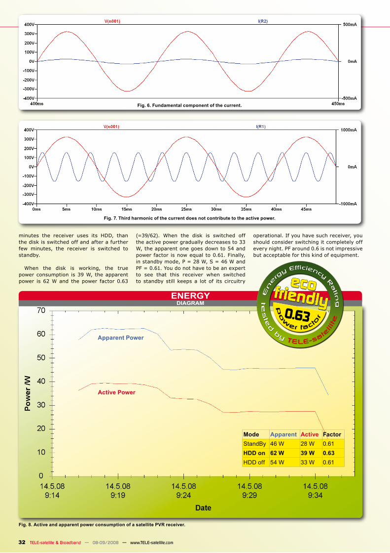
On our last drawing – Figure 7, you can see the third harmonic (150 Hz) and the voltage waveform. The harmonic is shown exaggerated for clarity. Such combination (voltage at fundamental frequency and cur-rent at third harmonic) does not produce
any active power. And this is also true for all higher harmonics,
Now the most important question. What is wrong with low power factor? If the appar-ent power is greater than the active power it means that in the wiring of your house and outside the house the greater current flows than it should. The wires have non-zero resistance, so some power is dissi-pated in them. Do you like your wires in the wall to get warm? You pay for such unnec-essary “heating”. Your energy meter counts it. Low PF presents even greater problem for energy providers. Their systems need to have extra current capacity in order to allow the usage of low PF loads. This means bigger transformer, thicker cables etc. On one hand, we - end users - have to pay for this. On the other hand, we use up more natural resources than necessary.
That’s why in many countries there are regulations forcing the equipment manu-facturers to ensure high power factor. This is not so easy as with simple motor but it can done by adding power factor correcting circuit. It requires extra components, occu-pies space inside the equipment and is not
for free. The equipment is bigger, heavier and costlier.
We know that many of our readers are environment cautious people. That’s why in the future TELE-satellite reports, we will present power consumption graphs of the devices we test. One such graph is shown in Figure 8. This is a satellite PVR receiver with embedded HDD. During the first few
Fig. 3. Power supply circuit of an exemplary satellite receiver.
Fig. 4. Mains voltage and supply current of the circuit shown in Figure 3.
Fig. 5. Frequency spectrum of the current drawn from the mains.
DIAGRAMENERGY
0.63
Mode Apparent Active FactorStandBy 46 W 28 W 0.61HDD on 62 W 39 W 0.63HDD off 54 W 33 W 0.61
Apparent Power
Active Power
32 TELE-satellite & Broadband — 08-09/2008 — www.TELE-satellite.com
Fig. 8. Active and apparent power consumption of a satellite PVR receiver.
minutes the receiver uses its HDD, than the disk is switched off and after a further few minutes, the receiver is switched to standby.
When the disk is working, the true power consumption is 39 W, the apparent power is 62 W and the power factor 0.63
(=39/62). When the disk is switched off the active power gradually decreases to 33 W, the apparent one goes down to 54 and power factor is now equal to 0.61. Finally, in standby mode, P = 28 W, S = 46 W and PF = 0.61. You do not have to be an expert to see that this receiver when switched to standby still keeps a lot of its circuitry
operational. If you have such receiver, you should consider switching it completely off every night. PF around 0.6 is not impressive but acceptable for this kind of equipment.
Fig. 6. Fundamental component of the current.
Fig. 7. Third harmonic of the current does not contribute to the active power.