Embed Size (px)
Citation preview

Power ElectronicsPower Electronics
Chapter 4 DC to AC Converters
( Inverters )

Pow
erE
lec t
roni
cs
2
Applications of InvertersApplications of Inverters
Conversion of electric power from DC type energy Conversion of electric power from DC type energy
sources to AC type loadsources to AC type load– BatteryBattery
– Photovoltaic cell (Solar cell)Photovoltaic cell (Solar cell)
– Fuel cellFuel cell
As a part of composite converterAs a part of composite converter– AC-DC-AC frequency converter (for AC motor drive)AC-DC-AC frequency converter (for AC motor drive)
– AC-DC-AC constant-voltage constant-frequency converter (for AC-DC-AC constant-voltage constant-frequency converter (for
uninterruptable power supplies)uninterruptable power supplies)
– AC-DC-AC Converters for induction heatingAC-DC-AC Converters for induction heating
– AC-DC-AC-DC switching power suppliesAC-DC-AC-DC switching power supplies

Pow
erE
lec t
roni
cs
3
OutlineOutline
4.1 Commutation4.1 Commutation
4.2 Voltage source inverters4.2 Voltage source inverters
4.3 Current source inverters4.3 Current source inverters
4.4 Multiple-inverter connections and multi-level inverters4.4 Multiple-inverter connections and multi-level inverters

Pow
erE
lec t
roni
cs
4
4.1 Commutation types4.1 Commutation types
A classification of invertersA classification of inverters– Square-wave inverters (are discussed in this chapter)Square-wave inverters (are discussed in this chapter)
– PWM inverters ( will be discussed in Chapter 6)PWM inverters ( will be discussed in Chapter 6)
The concept of commutationThe concept of commutation
Basic operation principle of invertersBasic operation principle of inverters
LoadS
1
S2
S3
S4
io
uo
Ud
t
u o
io
t1 t2

Pow
erE
lec t
roni
cs
5
4 types of commutation4 types of commutation
Device commutation: Device commutation: Fully-controlled devices: GTO, IGBT, MOSFETFully-controlled devices: GTO, IGBT, MOSFET
Line commutationLine commutation Phase-controlled rectifierPhase-controlled rectifier Phase-controlled AC controllerPhase-controlled AC controller Thyristor cycloconverterThyristor cycloconverter
Load commutationLoad commutation
Forced commutationForced commutation

Pow
erE
lec t
roni
cs
6
Load commutationLoad commutation
Condition: Load current is leading load voltageCondition: Load current is leading load voltage Application: capacitive load, synchronous motorApplication: capacitive load, synchronous motor

Pow
erE
lec t
roni
cs
7
Forced commutation Forced commutation (capacitance commutation) (capacitance commutation)
Direct-CoupledDirect-Coupled With Coupling-InductorWith Coupling-Inductor

Pow
erE
lec t
roni
cs
8
Another classification of commutationsAnother classification of commutations
Self-commutationSelf-commutation
Device commutation
Forced commutation
Line commutation
Load commutation
4 types of Commutations4 types of Commutations
External External commutationcommutation
For fully-controlled devices
For thyristors

Pow
erE
lec t
roni
cs
9
2 classes of inverters2 classes of inverters
Voltage Source Inverter (VSI)
Current Source Inverter (CSI)
Pow
erE
lec t
roni
cs
10
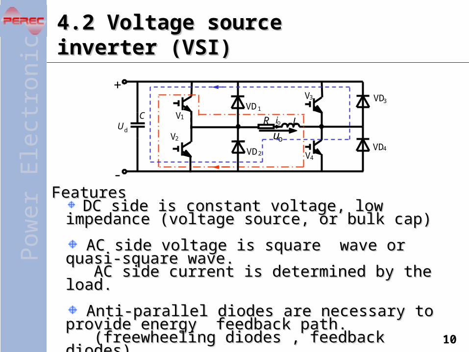
4.2 Voltage source inverter (VSI)4.2 Voltage source inverter (VSI)
DC side is constant voltage, low impedance DC side is constant voltage, low impedance (voltage source, or bulk cap)(voltage source, or bulk cap)
AC side voltage is square wave or quasi-square AC side voltage is square wave or quasi-square wave. wave. AC side current is determined by the load. AC side current is determined by the load.
Anti-parallel diodes are necessary to provide Anti-parallel diodes are necessary to provide energy feedback path.energy feedback path. (freewheeling diodes , feedback diodes)(freewheeling diodes , feedback diodes)
+
-
C R LUd
V1
V2
V3
V4
VD1
VD2
VD3
VD4
uo
io
FeaturesFeatures

Pow
erE
lec t
roni
cs
11
Single-phase half bridge VSISingle-phase half bridge VSI
The current conducting path is The current conducting path is determined by the polarity of load determined by the polarity of load voltage and load current. (This is true voltage and load current. (This is true for analysis of many power electronics for analysis of many power electronics circuits.)circuits.)
-
R LUd
io
uo
V1
V2
VD1
VD2
Ud
2
Ud
2
The magnitude of output square-wave voltage is UThe magnitude of output square-wave voltage is Udd/2./2.
uo
Um
io
t1 t2
t3 t4t5 t6
V1 V2 V1 V2
VD1 VD2 VD1 VD2
UG1
UG2

Pow
erE
lec t
roni
cs
12
Single-phase full bridge VSISingle-phase full bridge VSI
Operation principleOperation principle+
-
CR L
Ud
V1
V2
V3
V4
VD1
VD2
VD3
VD4
uo
io
The magnitude of output square-wave voltage is UThe magnitude of output square-wave voltage is Udd..
The effective value of output voltage (or fundamental The effective value of output voltage (or fundamental
output voltage) can be changed by changing U output voltage) can be changed by changing Udd..
uoU
m
io
t1t2
t3 t4t5t6
V1 V2 V1 V2
VD1 VD2 VD1 VD2
UG1,4
UG2,3
VD4 VD3 VD4 VD3
4 3 4 3V V V V

Pow
erE
lec t
roni
cs
13
Fourier series extension of output voltageFourier series extension of output voltage
Magnitude of output voltage fundamental component Magnitude of output voltage fundamental component
Effective value of output voltage fundamental Effective value of output voltage fundamental
componentcomponent
Single-phase full bridge VSISingle-phase full bridge VSI
Quantitative analysisQuantitative analysis
ttt
Uu
5sin
5
13sin
3
1sin
4 do
dd
o1m 27.14
UU
U
dd
1o 9.022
UU
U
(4-1)(4-1)
(4-2)(4-2)
(4-3)(4-3)

Pow
erE
lec t
roni
cs
14
Single-phase full bridge VSISingle-phase full bridge VSI
Output voltage control by phase-shiftOutput voltage control by phase-shift
+
-
CR L
Ud
V1
V2
V3
V4
VD1
VD2
VD 3
VD 4
uo
io

Pow
erE
lec t
roni
cs
15
Inverter with center-tapped transformerInverter with center-tapped transformer—push-pull inverter—push-pull inverter

Pow
erE
lec t
roni
cs
16
Three-phase VSIThree-phase VSI
180180oo conduction conduction
Dead time (blanking time) to Dead time (blanking time) to avoid “shoot through” avoid “shoot through”

Pow
erE
lec t
roni
cs
17
Three-phase VSIThree-phase VSI
Basic equations to obtain voltage waveformsBasic equations to obtain voltage waveforms
For line voltage For phase voltage of the load
0 WNVNUN UUU

Pow
erE
lec t
roni
cs
18
Three-phase VSIThree-phase VSI
Fourier series extension of output line-to-line voltageFourier series extension of output line-to-line voltage
Magnitude of output voltage (line-to-line) fundamental component Magnitude of output voltage (line-to-line) fundamental component
Effective value of output voltage (line-to-line) fundamental Effective value of output voltage (line-to-line) fundamental componentcomponent
Quantitative analysisQuantitative analysis
n
k tnn
tU
tttttU
u
sin)1(1
sin32
13sin13
111sin
11
17sin
7
15sin
5
1sin
32
d
dUV
dd
UV1m 1.132
UU
U
ddUV1m
UV1 78.06
2UU
UU
(4-8)(4-8)
(4-10)(4-10)
(4-11)(4-11)

Pow
erE
lec t
roni
cs
19
4.3 Current source inverter (CSI)4.3 Current source inverter (CSI)
DC side is constant current, high impedance (current source, or large inductor)
AC side current is quasi- square wave. AC side voltage is determined by the load.
No anti-parallel diodes are needed. sometimes series diodes are needed to block reverse voltage for other power semiconductor devices.
FeaturesFeatures

Pow
erE
lec t
roni
cs
20
Single-phase bridge CSISingle-phase bridge CSI
Parallel Resonant Inverter Parallel Resonant Inverter
A
C
R L
Ld
Id VT
1
VT2
VT3
VT4
LT1
LT2
LT3
LT4
uo
io
Switching frequency is a little higher Switching frequency is a little higher than the resonant frequency so that than the resonant frequency so that the the load becomes capacitive and load load becomes capacitive and load current is leading voltage to realize current is leading voltage to realize load commutation. load commutation.

Pow
erE
lec t
roni
cs
21
Three-phase self-commutated CSIThree-phase self-commutated CSI
120120oo conduction conduction

Pow
erE
lec t
roni
cs
22
Three-phase force-commutated CSIThree-phase force-commutated CSI

Pow
erE
lec t
roni
cs
23
Three-phase load-commutated CSIThree-phase load-commutated CSI
Pow
erE
lec t
roni
cs
24
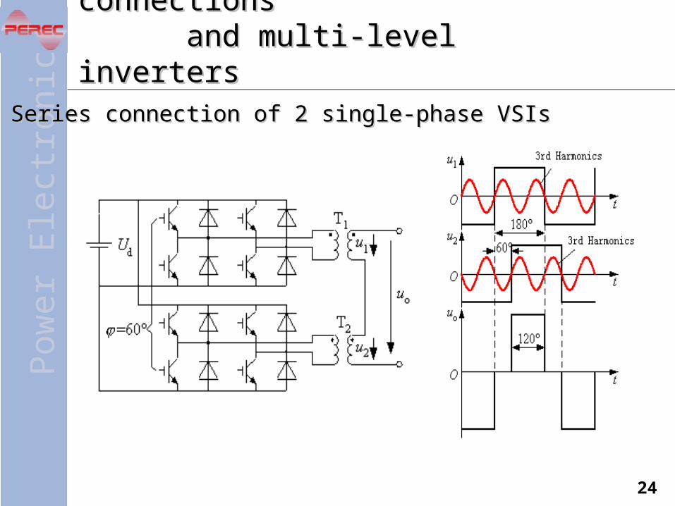
4.4 4.4 Multiple-inverter connections Multiple-inverter connections and multi-level inverters and multi-level invertersSeries connection of 2 single-phase VSIsSeries connection of 2 single-phase VSIs

Pow
erE
lec t
roni
cs
25
Series connection of 2 3-phase VSIsSeries connection of 2 3-phase VSIs

Pow
erE
lec t
roni
cs
26
Multi-level InvertersMulti-level Inverters
Ways to deal with higher voltage and achieve better Ways to deal with higher voltage and achieve better waveformwaveform– Series connection of multiple convertersSeries connection of multiple converters– Series connection of multiple switch devicesSeries connection of multiple switch devices
Major type of multi-level invertersMajor type of multi-level inverters– Neutral point clamped multi-level inverterNeutral point clamped multi-level inverter– Flying-capacitor multi-level inverterFlying-capacitor multi-level inverter– Cascade H-bridge( series connected H-bridges)Cascade H-bridge( series connected H-bridges)
In broad sense, previously discussed series In broad sense, previously discussed series connection of multiple inverters is also called multi-connection of multiple inverters is also called multi-level inverter.level inverter.In narrow sense, only NPC and FC structures are In narrow sense, only NPC and FC structures are called multi-level inverters.called multi-level inverters.

Pow
erE
lec t
roni
cs
27
Neutral-Point-Clamped 3-level inverterNeutral-Point-Clamped 3-level inverter

Pow
erE
lec t
roni
cs
28
Neutral-Point-Clamped 5-level inverterNeutral-Point-Clamped 5-level inverter
'
'
dU

Pow
erE
lec t
roni
cs
29
Flying-Capacitor 3-level inverterFlying-Capacitor 3-level inverter
UdUV
W
11V
12V
41V
42V
11VD
12VD
41VD
42VD

Pow
erE
lec t
roni
cs
30
Series connection of 3 H-bridgesSeries connection of 3 H-bridges
U
WV
dU
dU
dU
dU
dU
dU
dU
dU
dU