Embed Size (px)
Citation preview
Power Electronics Architecture R&D
Omer C. Onar
This presentation does not contain any proprietary, confidential, or otherwise restricted information
2013 U.S. DOE Hydrogen and Fuel Cells Program and Vehicle Technologies Program Annual Merit Review and Peer Evaluation Meeting
Oak Ridge National Laboratory
May 14, 2013 Project ID: APE056
2
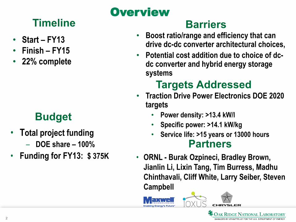
Overview
• Start – FY13 • Finish – FY15 • 22% complete
• Boost ratio/range and efficiency that can drive dc-dc converter architectural choices,
• Potential cost addition due to choice of dc-dc converter and hybrid energy storage systems
• Total project funding – DOE share – 100%
• Funding for FY13: $ 375K
Timeline
Budget
Barriers
Partners • ORNL - Burak Ozpineci, Bradley Brown,
Jianlin Li, Lixin Tang, Tim Burress, Madhu Chinthavali, Cliff White, Larry Seiber, Steven Campbell
Targets Addressed • Traction Drive Power Electronics DOE 2020
targets • Power density: >13.4 kW/l • Specific power: >14.1 kW/kg • Service life: >15 years or 13000 hours
3
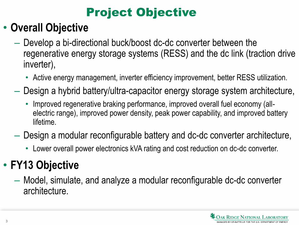
Project Objective • Overall Objective
– Develop a bi-directional buck/boost dc-dc converter between the regenerative energy storage systems (RESS) and the dc link (traction drive inverter), • Active energy management, inverter efficiency improvement, better RESS utilization.
– Design a hybrid battery/ultra-capacitor energy storage system architecture, • Improved regenerative braking performance, improved overall fuel economy (all-
electric range), improved power density, peak power capability, and improved battery lifetime.
– Design a modular reconfigurable battery and dc-dc converter architecture, • Lower overall power electronics kVA rating and cost reduction on dc-dc converter.
• FY13 Objective – Model, simulate, and analyze a modular reconfigurable dc-dc converter
architecture.
4
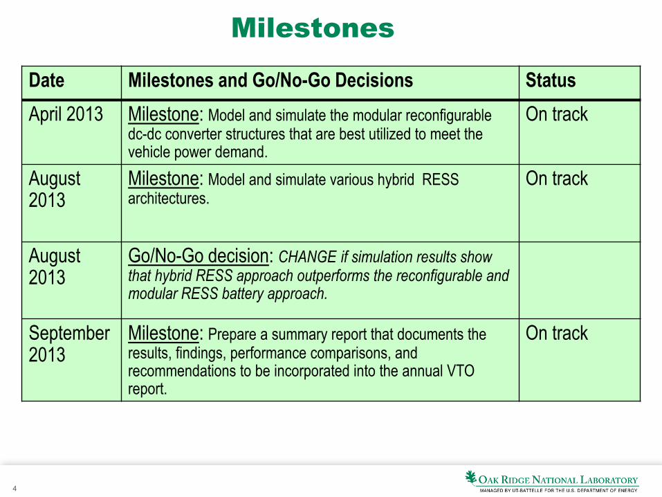
Milestones
Date Milestones and Go/No-Go Decisions Status April 2013 Milestone: Model and simulate the modular reconfigurable
dc-dc converter structures that are best utilized to meet the vehicle power demand.
On track
August 2013
Milestone: Model and simulate various hybrid RESS architectures.
On track
August 2013
Go/No-Go decision: CHANGE if simulation results show that hybrid RESS approach outperforms the reconfigurable and modular RESS battery approach.
September 2013
Milestone: Prepare a summary report that documents the results, findings, performance comparisons, and recommendations to be incorporated into the annual VTO report.
On track
5
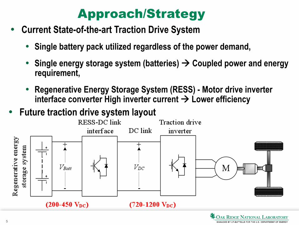
Approach/Strategy •! Current State-of-the-art Traction Drive System
•! Single battery pack utilized regardless of the power demand,
•! Single energy storage system (batteries) !! Coupled power and energy requirement,
•! Regenerative Energy Storage System (RESS) - Motor drive inverter interface converter High inverter current !! Lower efficiency
•! Future traction drive system layout
6
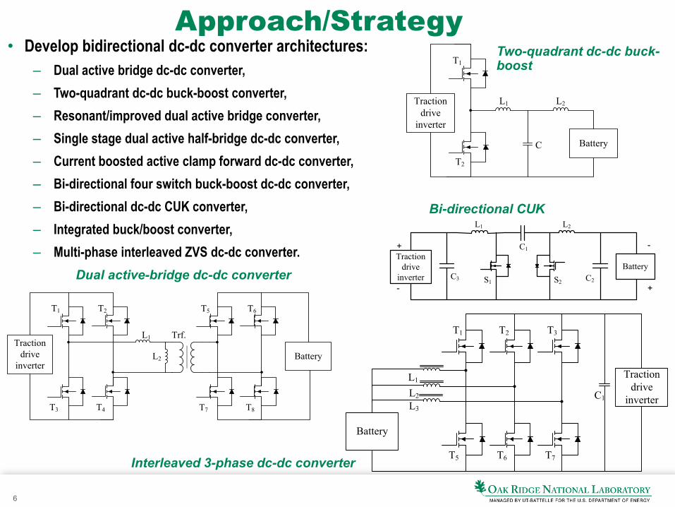
Approach/Strategy • Develop bidirectional dc-dc converter architectures:
– Dual active bridge dc-dc converter, – Two-quadrant dc-dc buck-boost converter, – Resonant/improved dual active bridge converter, – Single stage dual active half-bridge dc-dc converter, – Current boosted active clamp forward dc-dc converter, – Bi-directional four switch buck-boost dc-dc converter, – Bi-directional dc-dc CUK converter, – Integrated buck/boost converter, – Multi-phase interleaved ZVS dc-dc converter.
Battery
T1
T2
L1 L2
C
Traction drive
inverter
Two-quadrant dc-dc buck-boost
Traction drive
inverter
T1 T2
C1
T3
L1
L2L3
T5 T6 T7
Battery
Interleaved 3-phase dc-dc converter
Battery
T1
T3
T2
T4
L1
L2
Trf.
T5
T7
T6
T8
Traction drive
inverter
Dual active-bridge dc-dc converter Battery
+
+
-
-S1 S2
C1
C2C3
L1 L2
Traction drive
inverter
Bi-directional CUK
7
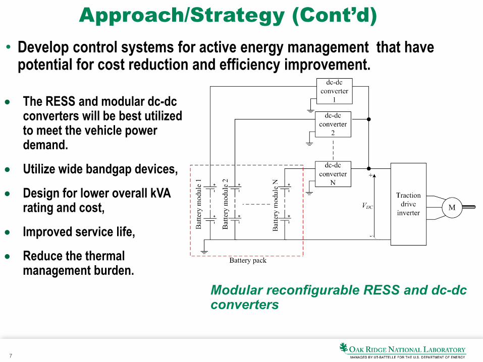
Approach/Strategy (Cont’d)
Modular reconfigurable RESS and dc-dc converters
• Develop control systems for active energy management that have potential for cost reduction and efficiency improvement.
• The RESS and modular dc-dc converters will be best utilized to meet the vehicle power demand.
• Utilize wide bandgap devices,
• Design for lower overall kVA rating and cost,
• Improved service life,
• Reduce the thermal management burden.
8
Technical Accomplishments and Progress – Overall
• Reviewed and modeled bi-directional dc-dc converter architectures that interface the RESS to the traction drive inverter and created a summary report discussing on the operation principles, controls, advantages and drawbacks.
• Reviewed and modeled hybrid RESS architectures and created a summary report based on the advantages, drawbacks, control systems, performance, number of parts, etc.
• Selected and modeled four battery/UC hybridization strategies. – Built simulation models of the battery and UC. – Modeled hybridization architectures. – Due to simulation time constraints, a portion of the UDDS drive cycle, t=[690, 760] that
includes acceleration, braking, and idling simulated for these hybridization architectures. – Collected and compared simulation results. – Created a comparison results table for these RESS hybridization architectures.
9
Technical Accomplishments and Progress
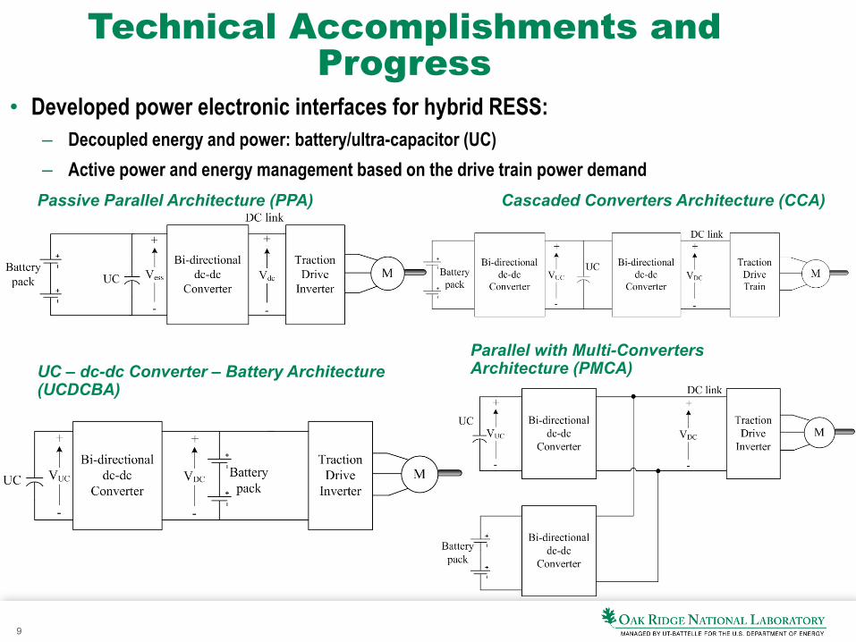
• Developed power electronic interfaces for hybrid RESS: – Decoupled energy and power: battery/ultra-capacitor (UC) – Active power and energy management based on the drive train power demand
Passive Parallel Architecture (PPA) Cascaded Converters Architecture (CCA)
Parallel with Multi-Converters Architecture (PMCA) UC – dc-dc Converter – Battery Architecture
(UCDCBA)
10
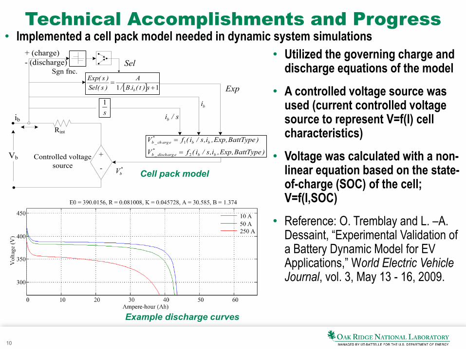
Technical Accomplishments and Progress • Implemented a cell pack model needed in dynamic system simulations
+
-Controlled voltage
source
Rint
Vb
ib
Sgn fnc.
)BattType,Exp,i,s/i(fV
)BattType,Exp,i,s/i(fV
bb*
eargdisch_b
bb*
eargch_b
2
1
=
=
s1
[ ] 11 +=
s)t(i.B/A
)s(Sel)s(Exp
b
*bV
Sel
Exp
s/ib
bi
+ (charge)- (discharge)
• Utilized the governing charge and discharge equations of the model
• A controlled voltage source was used (current controlled voltage source to represent V=f(I) cell characteristics)
• Voltage was calculated with a non-linear equation based on the state-of-charge (SOC) of the cell; V=f(I,SOC)
• Reference: O. Tremblay and L. –A. Dessaint, “Experimental Validation of a Battery Dynamic Model for EV Applications,” World Electric Vehicle Journal, vol. 3, May 13 - 16, 2009.
Cell pack model
Example discharge curves
11
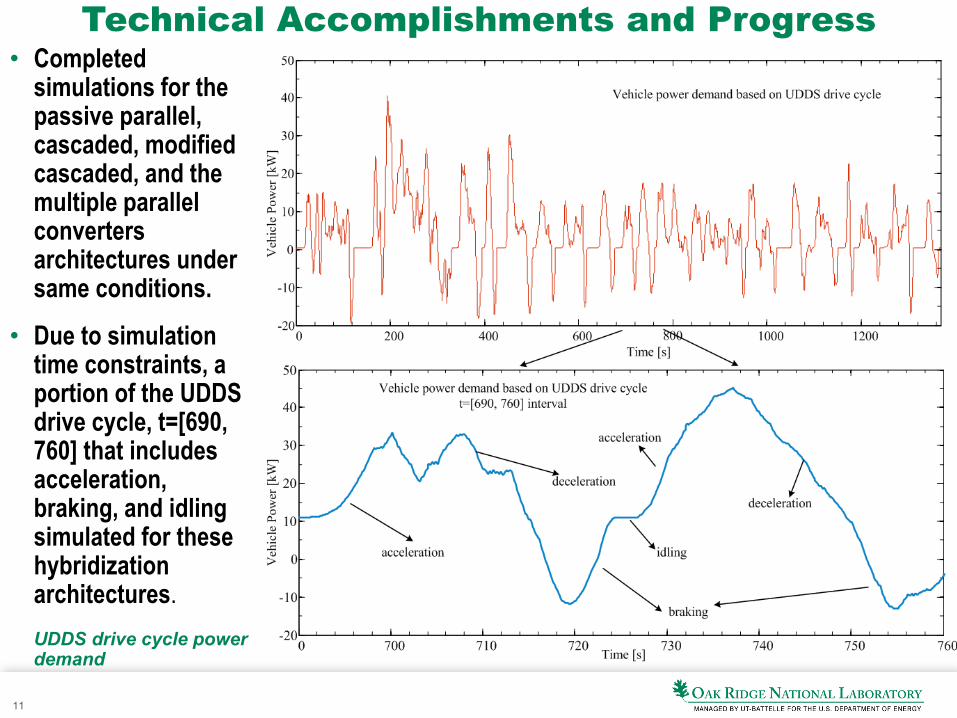
Technical Accomplishments and Progress • Completed
simulations for the passive parallel, cascaded, modified cascaded, and the multiple parallel converters architectures under same conditions.
• Due to simulation time constraints, a portion of the UDDS drive cycle, t=[690, 760] that includes acceleration, braking, and idling simulated for these hybridization architectures. UDDS drive cycle power demand
12
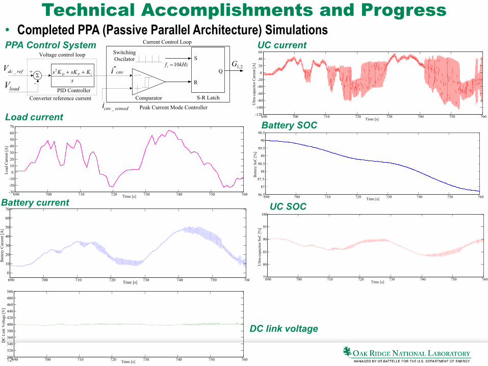
Technical Accomplishments and Progress • Completed PPA (Passive Parallel Architecture) Simulations
S
R
Q
sensedcnvi _
cnvi* 2,1GSwitching Oscilator
Comparator S-R Latch
Σ
Peak Current Mode Controller
PID ControllerConverter reference current
refdcV _
loadV+
- sKsKKs iPD ++2
kHzfs 10=
Voltage control loop
Current Control LoopPPA Control System
690 700 710 720 730 740 750 760-30
-20-10
01020
3040506070
Time [s]
Load
Cur
rent
[A]
690 700 710 720 730 740 750 760
0
10
20
30
40
50
60
70
Bat
tery
Cur
rent
[A]
Time [s]
690 700 710 720 730 740 750 760-120
-100
-80
-60
-40
-20
0
20
40
60
Ultr
a-ca
paci
tor C
urre
nt [A
]
Time [s]
690 700 710 720 730 740 750 76086.5
87
87.5
88
88.5
89
89.5
90
90.5
Time [s]
Bat
tery
SoC
[%]
690 700 710 720 730 740 750 76075
80
85
90
95
100
Time [s]
Ultr
a-ca
paci
tor S
oC [%
]
Load current
Battery current
UC current
Battery SOC
UC SOC
690 700 710 720 730 740 750 760300
320340360380400
420440460480500
DC
Lin
k V
olta
ge [V
]
Time [s]
DC link voltage
13
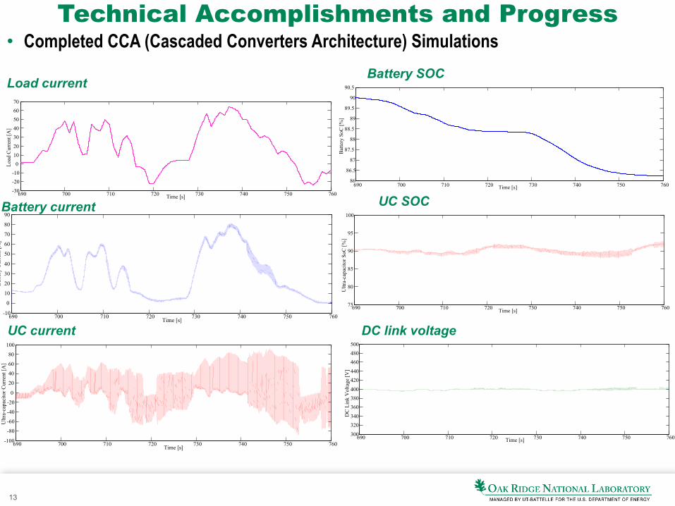
Technical Accomplishments and Progress • Completed CCA (Cascaded Converters Architecture) Simulations
690 700 710 720 730 740 750 760-30
-20-10
01020
3040506070
Time [s]
Load
Cur
rent
[A]
Load current
Battery current
UC current
Battery SOC
UC SOC
DC link voltage 690 700 710 720 730 740 750 760-10
0
10
20
30
40
50
60
70
80
90
Time [s]
Bat
tery
Cur
rent
[A]
690 700 710 720 730 740 750 760-100
-80
-60
-40
-20
0
20
40
60
80
100
Time [s]
Ultr
a-ca
paci
tor C
urre
nt [A
]
690 700 710 720 730 740 750 76086
86.5
87
87.5
88
88.5
89
89.5
90
90.5
Time [s]
Bat
tery
SoC
[%]
690 700 710 720 730 740 750 76075
80
85
90
95
100
Time [s]
Ultr
a-ca
paci
tor S
oC [%
]
690 700 710 720 730 740 750 760300
320340
360380400
420440
460480500
Time [s]
DC
Lin
k V
olta
ge [V
]
14
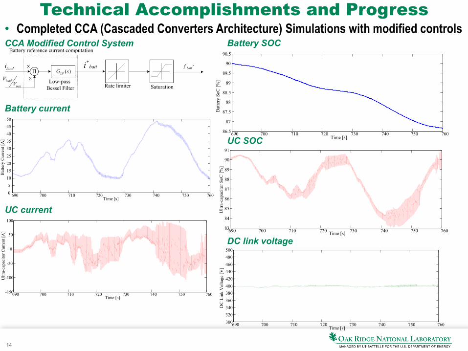
Technical Accomplishments and Progress • Completed CCA (Cascaded Converters Architecture) Simulations with modified controls
CCA Modified Control System
Battery current
UC current
Battery SOC
UC SOC
DC link voltage
batti*
Π )(sGLP
Low-pass Bessel Filter
Battery reference current computation
loadi
batt
loadV
V
×
×
'i batt*
Rate limiter Saturation
690 700 710 720 730 740 750 7600
510152025
3035404550
Time [s]
Bat
tery
Cur
rent
[A]
690 700 710 720 730 740 750 760-150
-100
-50
0
50
100
Time [s]
Ultr
a-ca
paci
tor C
urre
nt [A
]
690 700 710 720 730 740 750 76086.5
87
87.5
88
88.5
89
89.5
90
90.5
Time [s]
Bat
tery
SoC
[%]
690 700 710 720 730 740 750 76083
84
85
86
87
88
89
90
91
Time [s]
Ultr
a-ca
paci
tor S
oC [%
]
690 700 710 720 730 740 750 760300320340360380400420440460480500
Time [s]
DC
Lin
k V
olta
ge [V
]
15
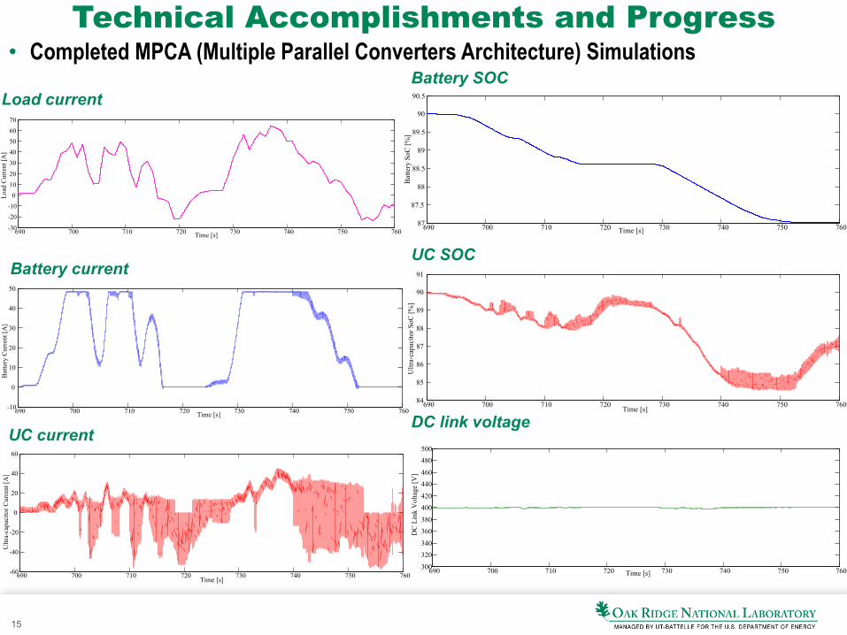
Technical Accomplishments and Progress • Completed MPCA (Multiple Parallel Converters Architecture) Simulations
Battery current
UC current
Battery SOC
UC SOC
DC link voltage 690 700 710 720 730 740 750 760-10
0
10
20
30
40
50
Time [s]
Bat
tery
Cur
rent
[A]
Time [s]
Ultr
a-ca
paci
tor C
urre
nt [A
]
690 700 710 720 730 740 750 760-60
-40
-20
0
20
40
60
Time [s]
Bat
tery
SoC
[%]
690 700 710 720 730 740 750 76087
87.5
88
88.5
89
89.5
90
90.5
Time [s]U
ltra-
capa
cito
r SoC
[%]
690 700 710 720 730 740 750 76084
85
86
87
88
89
90
91
Time [s]
DC
Lin
k V
olta
ge [V
]
690 700 710 720 730 740 750 760300
320340
360380
400420
440460
480500
690 700 710 720 730 740 750 760-30
-20-10
01020
3040506070
Time [s]
Load
Cur
rent
[A]
Load current
16
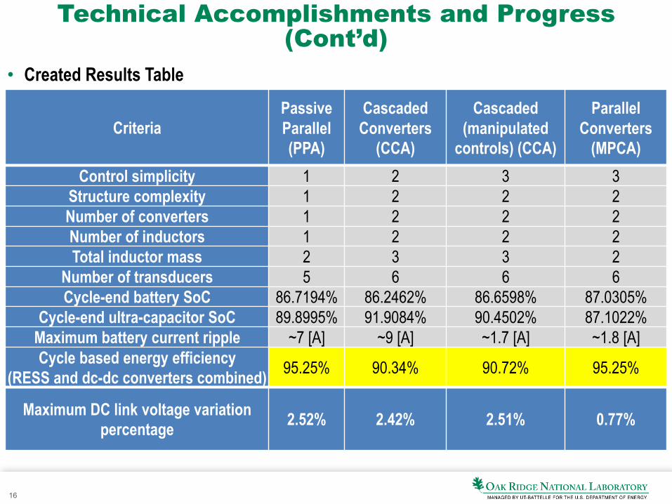
Technical Accomplishments and Progress (Cont’d)
• Created Results Table
Criteria Passive Parallel (PPA)
Cascaded Converters
(CCA)
Cascaded (manipulated
controls) (CCA)
Parallel Converters
(MPCA) Control simplicity 1 2 3 3
Structure complexity 1 2 2 2 Number of converters 1 2 2 2 Number of inductors 1 2 2 2 Total inductor mass 2 3 3 2
Number of transducers 5 6 6 6 Cycle-end battery SoC 86.7194% 86.2462% 86.6598% 87.0305%
Cycle-end ultra-capacitor SoC 89.8995% 91.9084% 90.4502% 87.1022% Maximum battery current ripple ~7 [A] ~9 [A] ~1.7 [A] ~1.8 [A] Cycle based energy efficiency
(RESS and dc-dc converters combined) 95.25% 90.34% 90.72% 95.25%
Maximum DC link voltage variation percentage 2.52% 2.42% 2.51% 0.77%
17
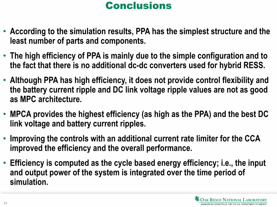
Conclusions
• According to the simulation results, PPA has the simplest structure and the least number of parts and components.
• The high efficiency of PPA is mainly due to the simple configuration and to the fact that there is no additional dc-dc converters used for hybrid RESS.
• Although PPA has high efficiency, it does not provide control flexibility and the battery current ripple and DC link voltage ripple values are not as good as MPC architecture.
• MPCA provides the highest efficiency (as high as the PPA) and the best DC link voltage and battery current ripples.
• Improving the controls with an additional current rate limiter for the CCA improved the efficiency and the overall performance.
• Efficiency is computed as the cycle based energy efficiency; i.e., the input and output power of the system is integrated over the time period of simulation.
18
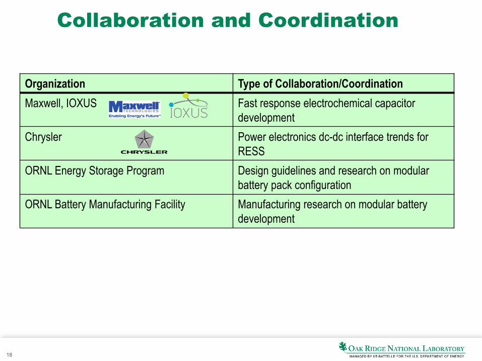
Collaboration and Coordination
Organization Type of Collaboration/Coordination Maxwell, IOXUS Fast response electrochemical capacitor
development Chrysler Power electronics dc-dc interface trends for
RESS ORNL Energy Storage Program Design guidelines and research on modular
battery pack configuration ORNL Battery Manufacturing Facility Manufacturing research on modular battery
development

19
Proposed Future Work
• Remainder of FY13 – Modeling, simulations, and analysis of modular reconfigurable dc-dc
converter architectures. Share results with APEEM team members.
• FY14 – Fabricate and test a candidate 10 kW reconfigurable dc-dc converter
architecture for experimental validation of models and simulations. Share results with APEEM team members.
• FY15 – Fabricate and test a full rated (55 kW) reconfigurable dc-dc converter
architecture. Share results with APEEM team members.
20
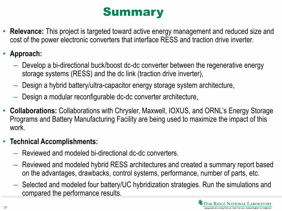
Summary
• Relevance: This project is targeted toward active energy management and reduced size and cost of the power electronic converters that interface RESS and traction drive inverter.
• Approach: – Develop a bi-directional buck/boost dc-dc converter between the regenerative energy
storage systems (RESS) and the dc link (traction drive inverter), – Design a hybrid battery/ultra-capacitor energy storage system architecture, – Design a modular reconfigurable dc-dc converter architecture,
• Collaborations: Collaborations with Chrysler, Maxwell, IOXUS, and ORNL’s Energy Storage Programs and Battery Manufacturing Facility are being used to maximize the impact of this work.
• Technical Accomplishments: – Reviewed and modeled bi-directional dc-dc converters. – Reviewed and modeled hybrid RESS architectures and created a summary report based
on the advantages, drawbacks, control systems, performance, number of parts, etc. – Selected and modeled four battery/UC hybridization strategies. Run the simulations and
compared the performance results.