Embed Size (px)
DESCRIPTION
Efficient Power Control in CDMA Systems ByRishabh AgarwalPD Aditya
Citation preview
Power Control in CDMA Cellular System
By,P. D. Aditya , Rishabh Agarwal
BE IV/IV ECEUniversity College Of Engineering,
Osmania University
Contents
Introduction
Power in Wireless Networks
Main disadvantage in CDMA
Capacity of CDMA System
Power Control Schemes
Introduction Code Division Multiple Access
Narrowband message signal multiplied with spreading signal
Unique Pseudo Random Noise code given to each user- orthogonal to other users
Correlation at receiver- Detection of specific code word
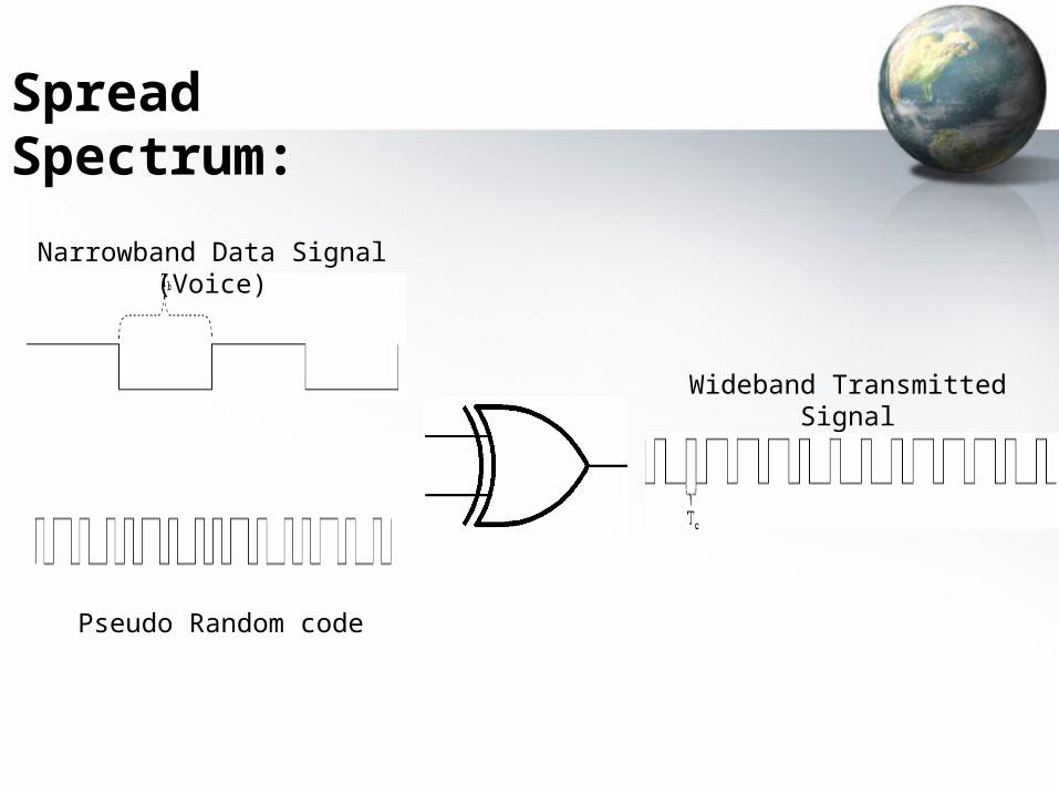
Narrowband Data Signal (Voice)
Pseudo Random code
Wideband Transmitted Signal
Spread Spectrum:
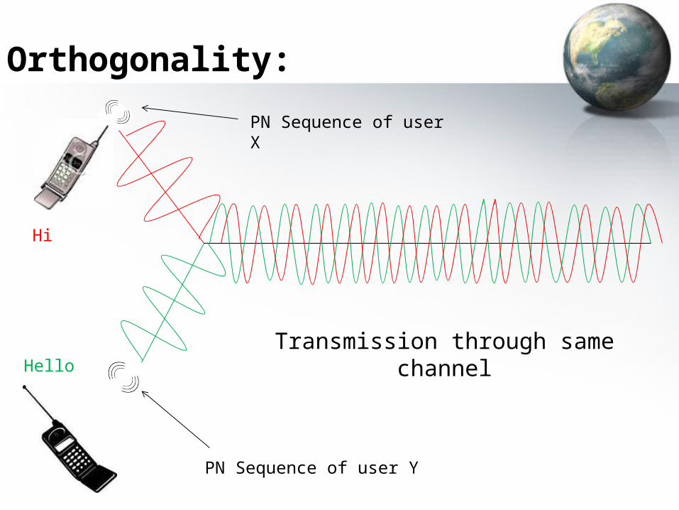
Hi
Hello
Orthogonality:
Transmission through same channel
PN Sequence of user X
PN Sequence of user Y
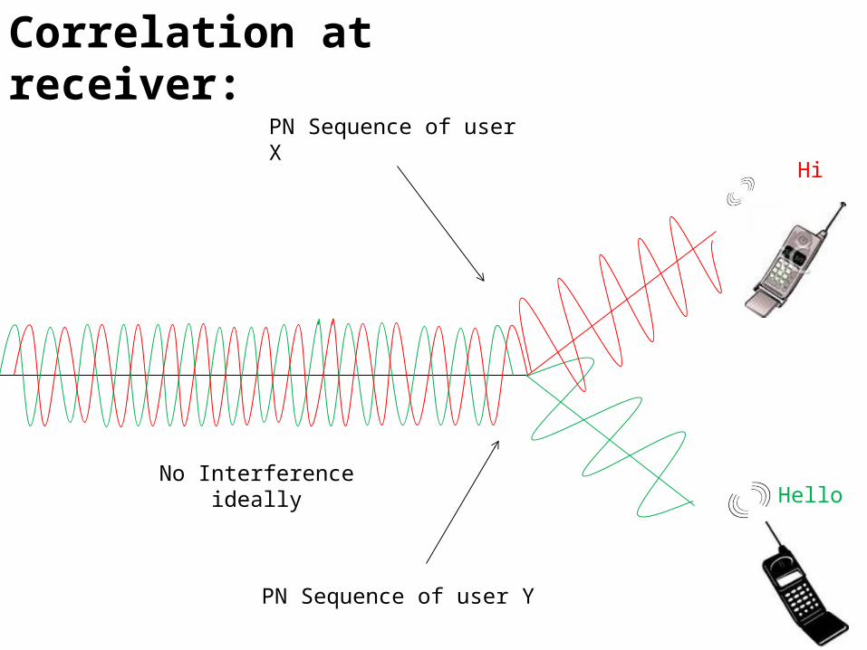
Correlation at receiver:
Hi
Hello
PN Sequence of user X
PN Sequence of user Y
No Interference ideally
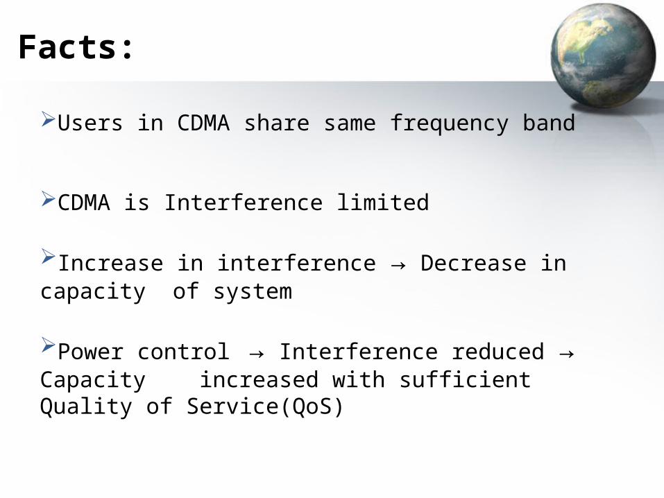
Users in CDMA share same frequency band
CDMA is Interference limited
Increase in interference → Decrease in capacity of system
Power control → Interference reduced → Capacity increased with sufficient Quality of Service(QoS)
Facts:
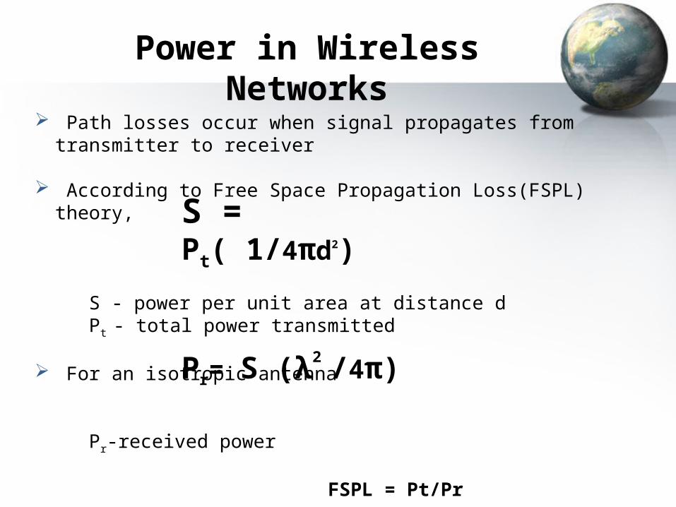
Power in Wireless Networks
Path losses occur when signal propagates from transmitter to receiver
According to Free Space Propagation Loss(FSPL) theory,
S - power per unit area at distance dPt - total power transmitted
For an isotropic antenna
Pr-received power
FSPL = Pt/Pr
S = Pt( 1/4πd2)
Pr= S (λ2 /4π)

Received signal strength - Raleigh fading:
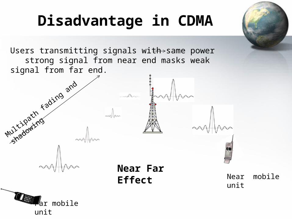
Disadvantage in CDMA
Users transmitting signals with same power strong signal from near end masks weak signal from far end.
Multipath
fading an
d shad
owing
Far mobile unit
Near mobile unitNear Far Effect
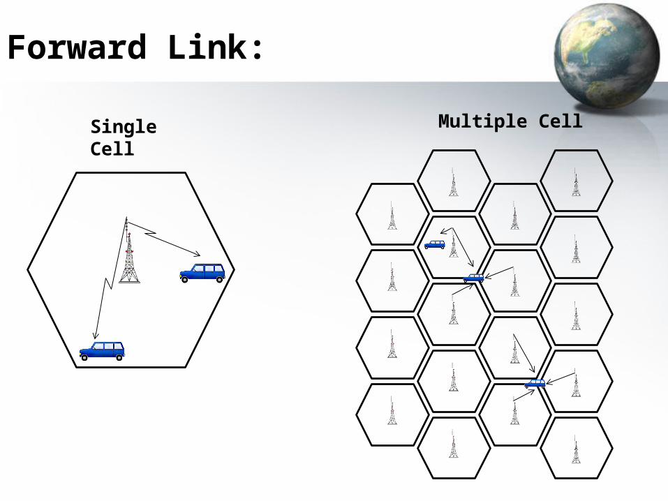
Forward Link:
Single Cell Multiple Cell
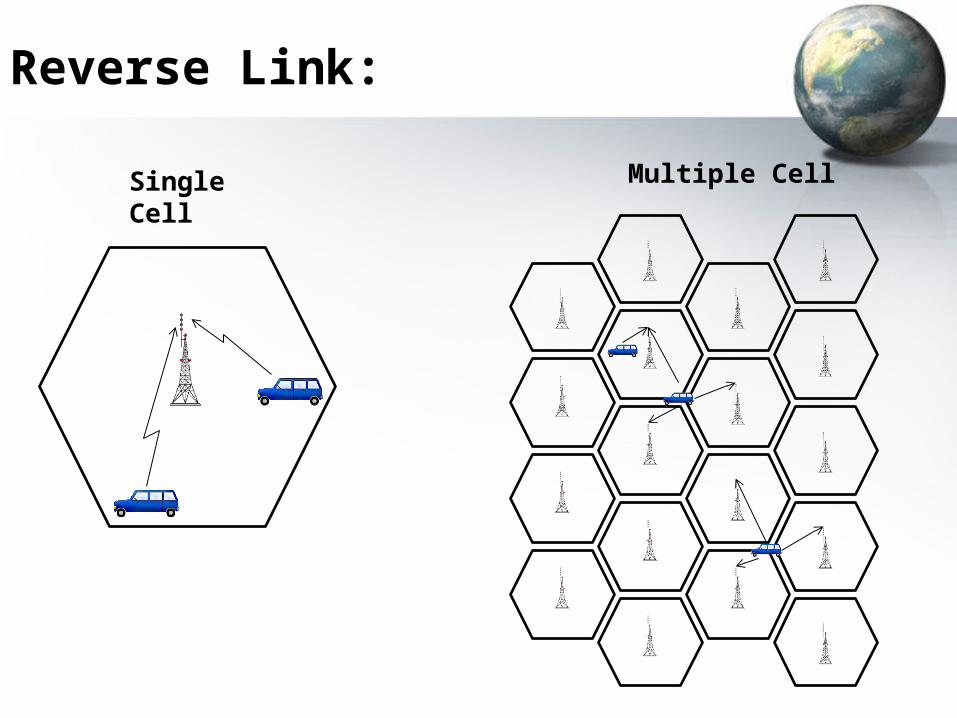
Reverse Link:
Single Cell Multiple Cell
Capacity in CDMA System
Forward link coherent demodulation by pilot carrier
Performance superior to reverse link
Reverse link non coherent reception, non coordinated, independent fading of all users.
Hence emphasis is made on reverse link capacity.
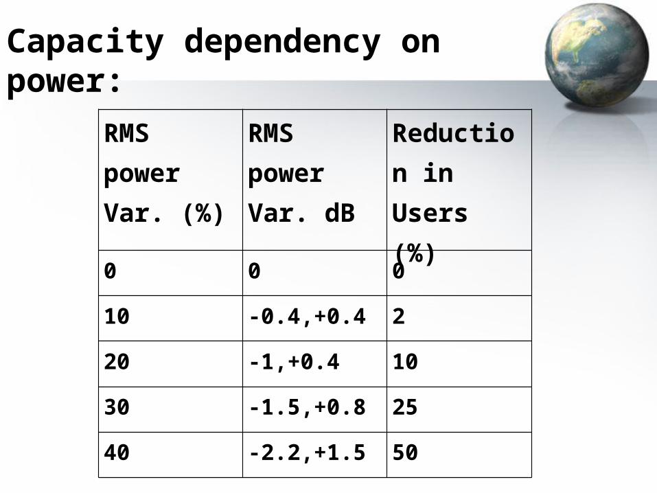
Capacity dependency on power:
RMS powerVar. (%)
RMS powerVar. dB
Reduction inUsers (%)
0 0 0
10 -0.4,+0.4 2
20 -1,+0.4 10
30 -1.5,+0.8 25
40 -2.2,+1.5 50
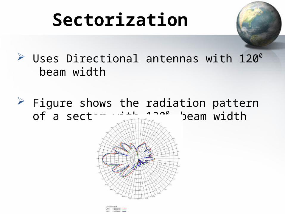
Sectorization
Uses Directional antennas with 1200 beam width
Figure shows the radiation pattern of a sector with 1200 beam width
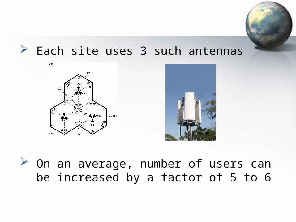
Each site uses 3 such antennas
On an average, number of users can be increased by a factor of 5 to 6
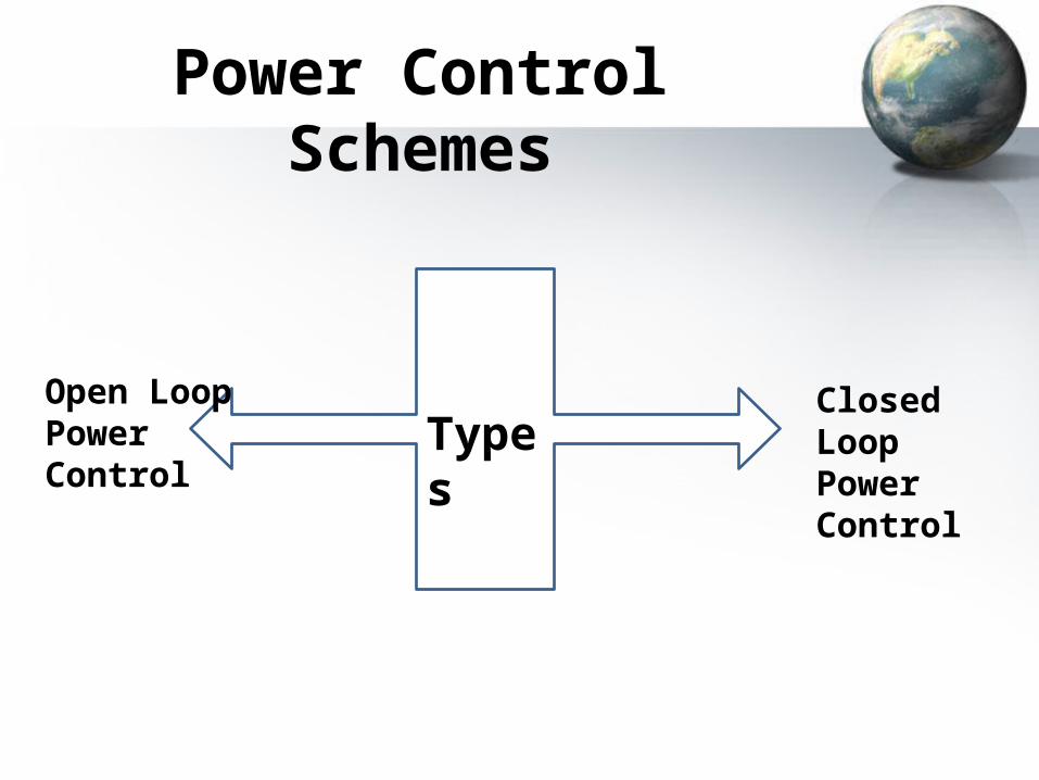
Power Control Schemes
Open Loop Power Control
Closed Loop Power Control
Types
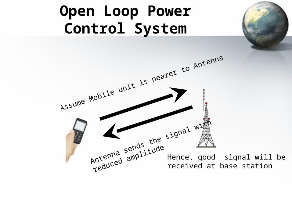
Open Loop Power Control System
Assume Mobile unit is nearer to Antenna
Hence, good signal will be received at base station
Antenna sends the signal with
reduced amplitude
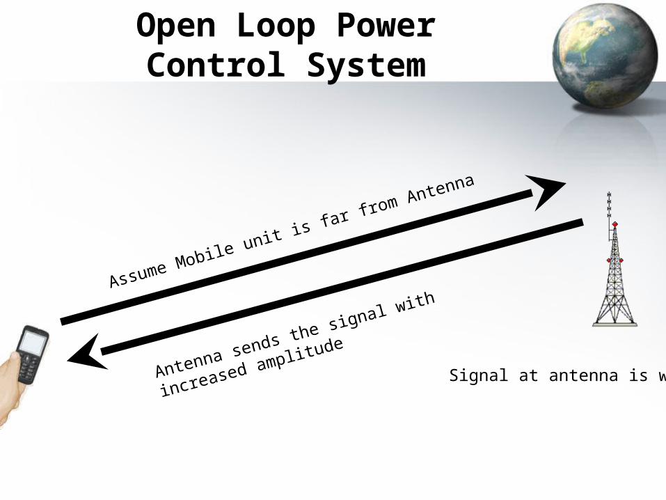
Open Loop Power Control System
Assume Mobile unit is far from Antenna
Signal at antenna is weakAntenna sends the signal with increased amplitude
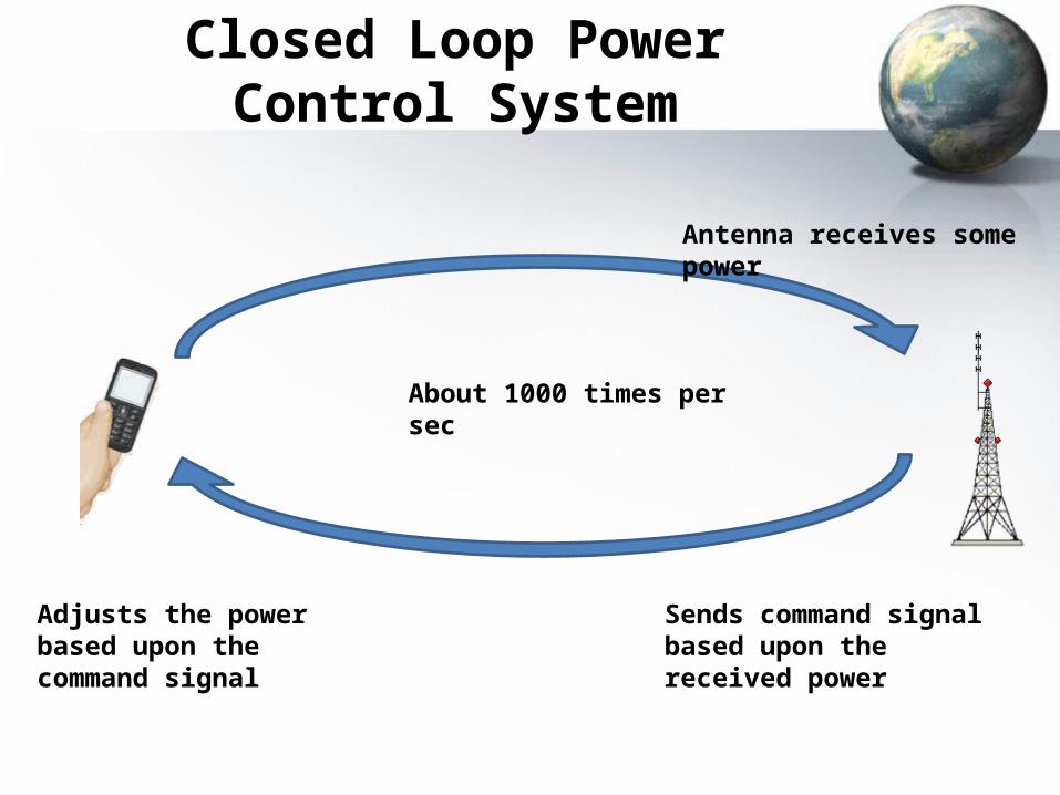
Closed Loop Power Control System
Antenna receives some power
Sends command signal based upon the received power
Adjusts the power based upon the command signal
About 1000 times per sec
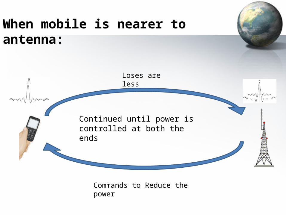
When mobile is nearer to antenna:
Loses are less
Commands to Reduce the power
Continued until power is controlled at both the ends
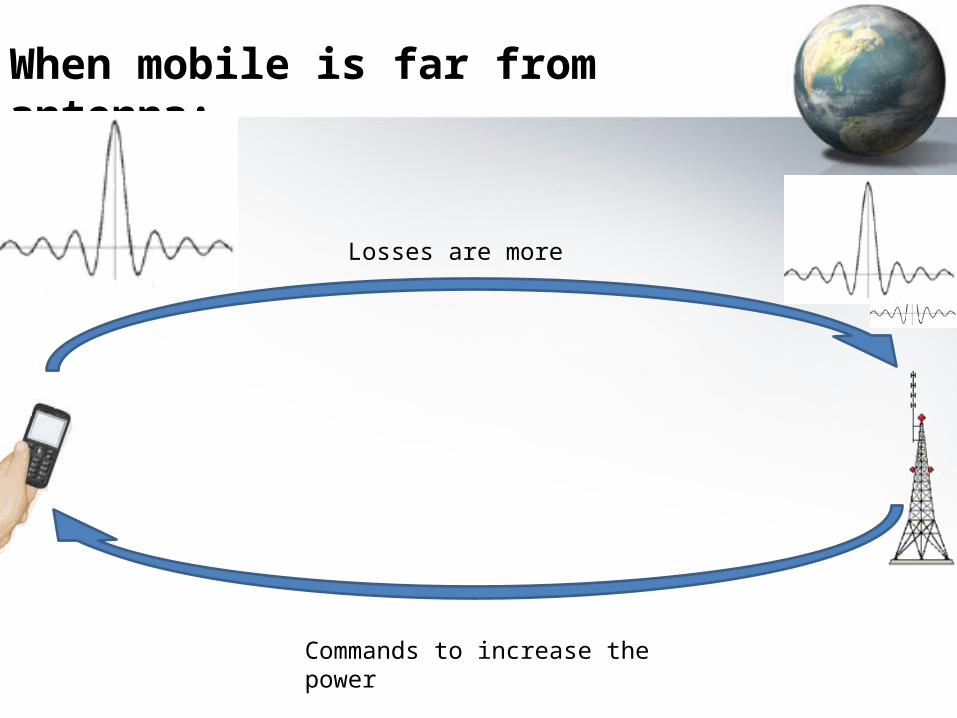
When mobile is far from antenna:
Losses are more
Commands to increase the power
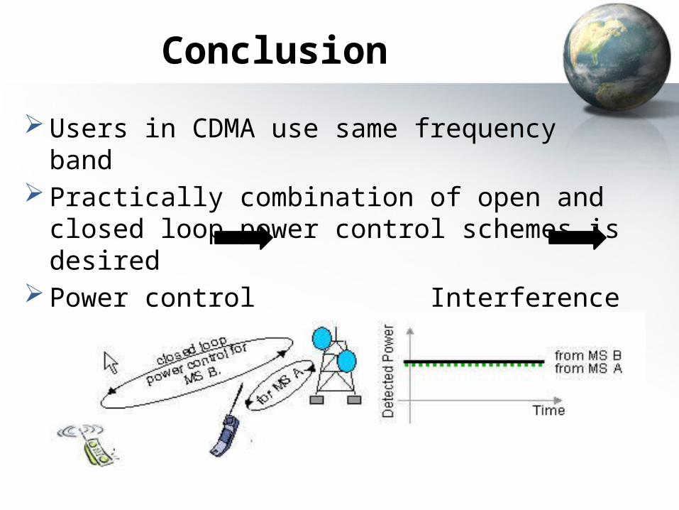
Conclusion
Users in CDMA use same frequency band Practically combination of open and closed loop
power control schemes is desired Power control Interference minimized
Capacity increased
References 1. Akinniyi, A.R., Lehnert, J.S. “Characterization of Noncoherent spread spectrum multiple access communications” IEEE transaction on communication. Vol. 42, No. 1, January, 1994. 2. Felhaure, T. Klein, A. and Baier, P.W. “A low cost method for CDMA and other application to separate non orthogonal signals” IEEE transaction on communication. 3. Grandhi.S “Centralized power control in cellular radio systems” Trans.On Vehicular tech. vol.42 No. 4, November, 1993. 4. www.cdmaonline.com 5. www.itr.unisa.edu.au/research/publications/thesis 6. www.cdmaonline.com 7. http://ieeexplore.ieee.org

Thank you

Any Queries