Embed Size (px)
Citation preview
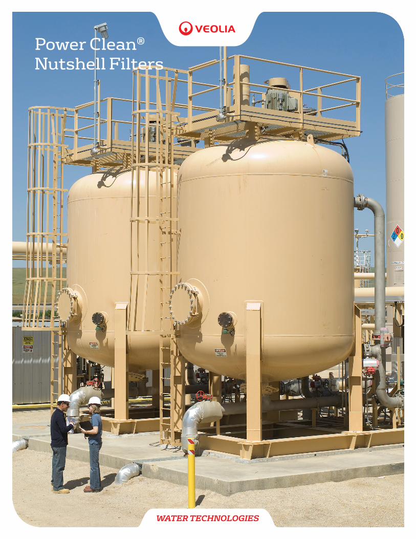
Power Clean®
Nutshell Filters
WATER TECHNOLOGIES
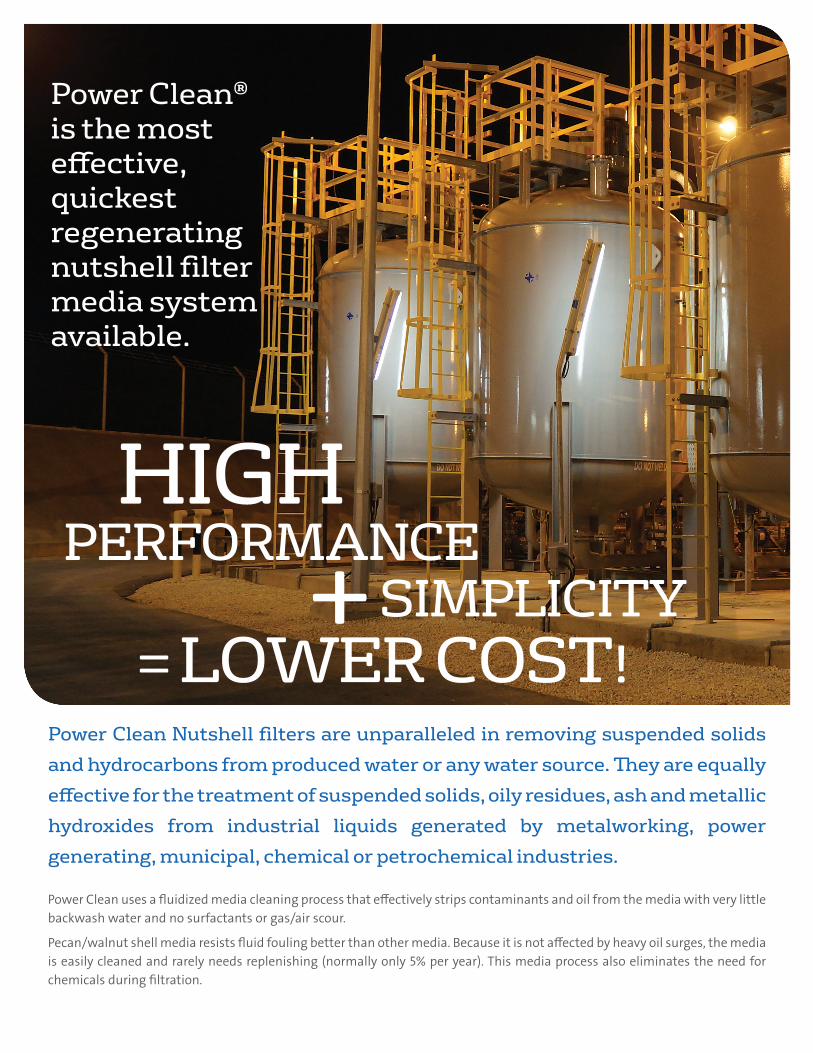
Power Clean® is the most effective, quickest regenerating nutshell filter media system available.
HIGHPERFORMANCE + SIMPLICITY = LOWER COST!
Power Clean Nutshell filters are unparalleled in removing suspended solids and hydrocarbons from produced water or any water source. They are equally effective for the treatment of suspended solids, oily residues, ash and metallic hydroxides from industrial liquids generated by metalworking, power generating, municipal, chemical or petrochemical industries.
Power Clean uses a fluidized media cleaning process that effectively strips contaminants and oil from the media with very little backwash water and no surfactants or gas/air scour.
Pecan/walnut shell media resists fluid fouling better than other media. Because it is not affected by heavy oil surges, the media is easily cleaned and rarely needs replenishing (normally only 5% per year). This media process also eliminates the need for chemicals during filtration.
• Media cleaned in only 12 minutes
• Patented fluidized bed process
• Only 5% replacement media required per year
• Reclaims more oil than other media
• Upstream flow interrupted for only sixty seconds.
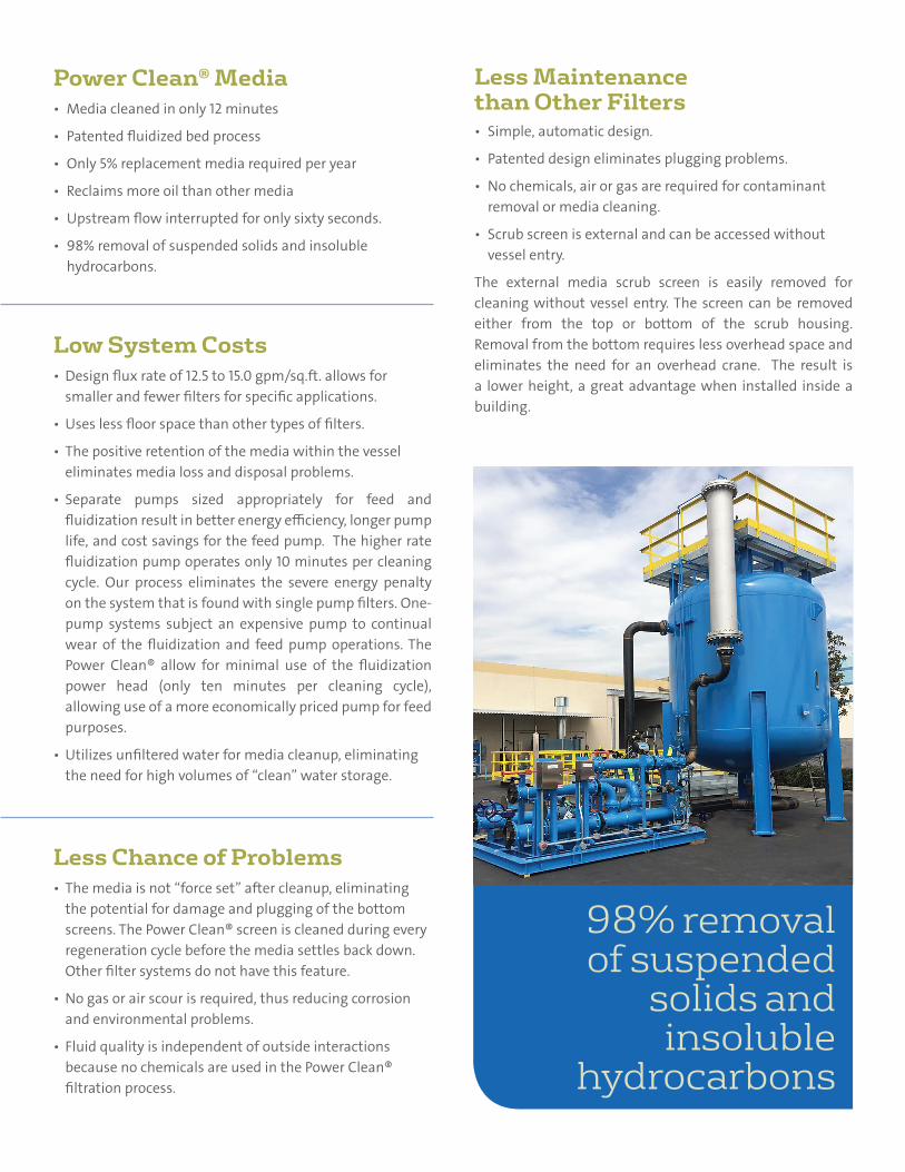
• 98% removal of suspended solids and insoluble hydrocarbons.
• The media is not “force set” after cleanup, eliminating the potential for damage and plugging of the bottom screens. The Power Clean® screen is cleaned during every regeneration cycle before the media settles back down. Other filter systems do not have this feature.
• No gas or air scour is required, thus reducing corrosion and environmental problems.
• Fluid quality is independent of outside interactions because no chemicals are used in the Power Clean® filtration process.
• Simple, automatic design.
• Patented design eliminates plugging problems.
• No chemicals, air or gas are required for contaminant removal or media cleaning.
• Scrub screen is external and can be accessed without vessel entry.
The external media scrub screen is easily removed for cleaning without vessel entry. The screen can be removed either from the top or bottom of the scrub housing. Removal from the bottom requires less overhead space and eliminates the need for an overhead crane. The result is a lower height, a great advantage when installed inside a building.
• Design flux rate of 12.5 to 15.0 gpm/sq.ft. allows for smaller and fewer filters for specific applications.
• Uses less floor space than other types of filters.
• The positive retention of the media within the vessel eliminates media loss and disposal problems.
• Separate pumps sized appropriately for feed and fluidization result in better energy efficiency, longer pump life, and cost savings for the feed pump. The higher rate fluidization pump operates only 10 minutes per cleaning cycle. Our process eliminates the severe energy penalty on the system that is found with single pump filters. One-pump systems subject an expensive pump to continual wear of the fluidization and feed pump operations. The Power Clean® allow for minimal use of the fluidization power head (only ten minutes per cleaning cycle), allowing use of a more economically priced pump for feed purposes.
• Utilizes unfiltered water for media cleanup, eliminating the need for high volumes of “clean” water storage.
Power Clean® Media
Less Chance of Problems
Less Maintenance than Other Filters
Low System Costs
98% removal of suspended
solids and insoluble
hydrocarbons
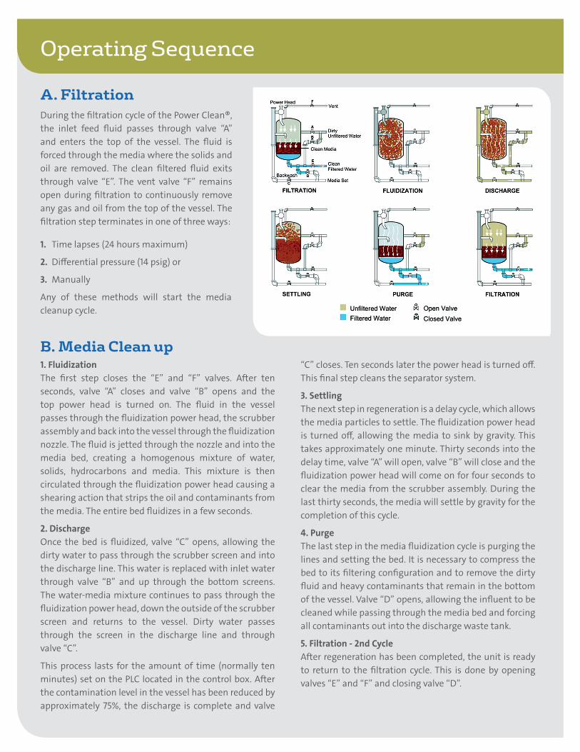
Operating Sequence
During the filtration cycle of the Power Clean®, the inlet feed fluid passes through valve “A” and enters the top of the vessel. The fluid is forced through the media where the solids and oil are removed. The clean filtered fluid exits through valve “E”. The vent valve “F” remains open during filtration to continuously remove any gas and oil from the top of the vessel. The filtration step terminates in one of three ways:
1. Time lapses (24 hours maximum)
2. Differential pressure (14 psig) or
3. Manually
Any of these methods will start the media cleanup cycle.
A. Filtration
B. Media Clean up1. FluidizationThe first step closes the “E” and “F” valves. After ten seconds, valve “A” closes and valve “B” opens and the top power head is turned on. The fluid in the vessel passes through the fluidization power head, the scrubber assembly and back into the vessel through the fluidization nozzle. The fluid is jetted through the nozzle and into the media bed, creating a homogenous mixture of water, solids, hydrocarbons and media. This mixture is then circulated through the fluidization power head causing a shearing action that strips the oil and contaminants from the media. The entire bed fluidizes in a few seconds.
2. DischargeOnce the bed is fluidized, valve “C” opens, allowing the dirty water to pass through the scrubber screen and into the discharge line. This water is replaced with inlet water through valve “B” and up through the bottom screens. The water-media mixture continues to pass through the fluidization power head, down the outside of the scrubber screen and returns to the vessel. Dirty water passes through the screen in the discharge line and through valve “C”.
This process lasts for the amount of time (normally ten minutes) set on the PLC located in the control box. After the contamination level in the vessel has been reduced by approximately 75%, the discharge is complete and valve
“C” closes. Ten seconds later the power head is turned off. This final step cleans the separator system.
3. SettlingThe next step in regeneration is a delay cycle, which allows the media particles to settle. The fluidization power head is turned off, allowing the media to sink by gravity. This takes approximately one minute. Thirty seconds into the delay time, valve “A” will open, valve “B” will close and the fluidization power head will come on for four seconds to clear the media from the scrubber assembly. During the last thirty seconds, the media will settle by gravity for the completion of this cycle.
4. PurgeThe last step in the media fluidization cycle is purging the lines and setting the bed. It is necessary to compress the bed to its filtering configuration and to remove the dirty fluid and heavy contaminants that remain in the bottom of the vessel. Valve “D” opens, allowing the influent to be cleaned while passing through the media bed and forcing all contaminants out into the discharge waste tank.
5. Filtration - 2nd CycleAfter regeneration has been completed, the unit is ready to return to the filtration cycle. This is done by opening valves “E” and “F” and closing valve “D”.
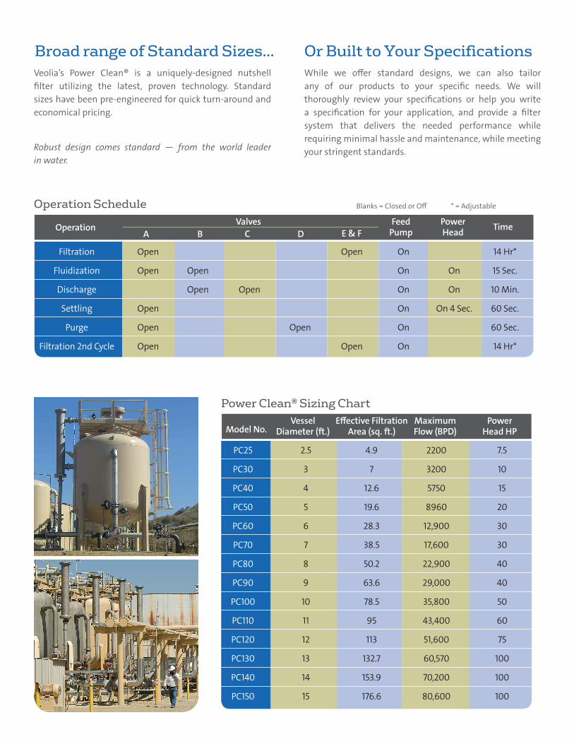
Blanks = Closed or Off * = Adjustable
PC25 2.5 4.9 2200 7.5
PC30 3 7 3200 10
PC40 4 12.6 5750 15
PC50 5 19.6 8960 20
PC60 6 28.3 12,900 30
PC70 7 38.5 17,600 30
PC80 8 50.2 22,900 40
PC90 9 63.6 29,000 40
PC100 10 78.5 35,800 50
PC110 11 95 43,400 60
PC120 12 113 51,600 75
PC130 13 132.7 60,570 100
PC140 14 153.9 70,200 100
PC150 15 176.6 80,600 100
Model No.MaximumFlow (BPD)
Effective Filtration Area (sq. ft.)
VesselDiameter (ft.)
PowerHead HP
Veolia’s Power Clean® is a uniquely-designed nutshell filter utilizing the latest, proven technology. Standard sizes have been pre-engineered for quick turn-around and economical pricing.
Robust design comes standard — from the world leader in water.
While we offer standard designs, we can also tailor any of our products to your specific needs. We will thoroughly review your specifications or help you write a specification for your application, and provide a filter system that delivers the needed performance while requiring minimal hassle and maintenance, while meeting your stringent standards.
Broad range of Standard Sizes… Or Built to Your Specifications
Power Clean® Sizing Chart
Filtration Open Open On 14 Hr*
Fluidization Open Open On On 15 Sec.
Discharge Open Open On On 10 Min.
Settling Open On On 4 Sec. 60 Sec.
Purge Open Open On 60 Sec.
Filtration 2nd Cycle Open Open On 14 Hr*
OperationA DB E & F
TimeValvesC
FeedPump
PowerHead
Operation Schedule
©VW
S Co
mm
unic
atio
ns -
10/2
014
Brea, CA, USAtel +1 (714) 986-5300
Veolia Water Technologies