Embed Size (px)
Citation preview

3
Powder Injection Molding of Metal and Ceramic Parts
Joamiacuten Gonzaacutelez-Gutieacuterrez Gustavo Beulke Stringari and Igor Emri Center for Experimental Mechanics University of Ljubljana Ljubljana
Slovenia
1 Introduction
Powder injection molding (PIM) is a technology for manufacturing complex precision net-shape components from either metal or ceramic powder The potential of PIM lies in its ability to combine the design flexibility of plastic injection molding and the nearly unlimited choice of material offered by powder metallurgy making it possible to combine multiple parts into a single one (Hausnerovaacute 2011) Furthermore PIM overcomes the dimensional and productivity limits of isostatic pressing and slip casting the defects and tolerance limitations of investment casting the mechanical strength of die-cast parts and the shape limitation of traditional powder compacts (Tandon 2008)
Due to the demand of high performance materials and the miniaturization of complex components in various fields PIM market has exceeded the $ 1 billion mark in 2007 becoming approximately six times larger than 15 years before (German 2008) This impressive growth rate is not expected to slow down in the next few years as a recent report from Global Industry Analysts announced that together world metal and ceramic PIM market is forecast to reach $ 37 billion by the year 2017 (Global Industry Analysts [GIA] 2011) Metal powder injection molding (MIM) is still considered the largest segment of this market accounting for more than 70 of global output Although PIM is globally widespread Europe and Asia-Pacific account for a major share of MIM segment while USA is still the largest market for Ceramic Injection Molding (CIM) (GIA 2011)
In Europe the MIM production is dominated by automotive applications and the so called consumer market (which includes watches and eyeglasses) while the North American production is mainly applied to the medicalhealthcare field On the other hand the Asian production considered the largest one is dominated by consumer electronics and information technology applications The consumer electronics market is indeed one of the drivers behind MIM whose growth is largely taking place in Asia specifically in Taiwan Malaysia Thailand China Singapore and South Korea Another growth factor is the expansion of medical component production also in Asia as a larger population gains access to improved health care (German 2008)
A recent increase in MIM sales has generated a need for new equipment with a simultaneous investment in research and development Typically leader companies invest an average of 105 of sales in the combination of capital expansion and research Besides
wwwintechopencom
Some Critical Issues for Injection Molding
66
this several contract electronic assembly firms that used to purchase MIM components from custom molders have now elected to make from MIM a captive operation (German 2008) This could lead to rapid growth for those operations since the relationship between design and production can be improved
Stainless steel continues to dominate MIM applications accounting for around half of the global production reflecting the capture of components that would have otherwise gone to investment casting Nevertheless other materials as copper nickel alloys bronze and more recently tungsten alloys and titanium also represent important markets (German 2008) On the other hand the CIM market is mainly dominated by products made out of alumina zirconia and silicon or aluminium nitride powders (Ruprecht et al 2002)
Typical components produced by PIM either MIM or CIM range from 0002 to over 100 g (German 2008) Furthermore in both segments it is clear the progressive move towards smaller products demanding improved technologies regarding machinery process and materials hence leaving a still open field for applied research
2 Overview of process
The PIM process presents countless variations which are used in the industry today Invariably it consists of four steps (Gonccedilalves 2001 Tay et al 2009)
Feedstock preparation Injection molding Debinding Sintering
In Fig 1 a flow chart illustrating the main stages of PIM is presented
TEMP
Binder
Binder PowderFeed-
stock
Solvent
Catalyst
Heat
Mixing of multi-component binder
and metal (or ceramic) powder
Injection molding of the mixture (feedstock)
Debinding of green partSintering of brown part
Binder
Fig 1 Flow chart illustrating the main stages of PIM
wwwintechopencom
Powder Injection Molding of Metal and Ceramic Parts
67
The starting material for PIM usually termed feedstock is a homogeneous pelletized
mixture of metal or ceramic powder and an organic multi-component binder The binder
and the powder are combined in a variety of compounding equipment such as extruders
and mixers The mixture is then pelletized to an appropriate shape for feeding into the
molding machine The binder is simply a carrier medium for the powder and once a part is
molded the binder is removed in a subsequent step
The injection molding process is mainly identical to conventional plastic injection molding
Nevertheless some machine hardware changes are usually required to process a specific
feedstock based on their compressibility and viscosity Control of the molding process is
vital for maintaining tight tolerances in subsequent steps Most design advantages of PIM
technology are captured during molding by relying on the flexibility of incorporating
complexities in the tool A molded part is called a ldquogreen partrdquo and is oversized to allow
shrinkage during sintering (Tandon 2008)
Before sintering it is necessary to remove the binder from the molded part The debinding
is the most expensive and time-consuming stage in the PIM technology This removal
process should be based on a progressive opening of the surface channels to facilitate the
removal of vapors inside the nucleus (Gonccedilalves 2001) Three main methods can be
applied depending on the composition of the binder thermal solvent and catalytic In
thermal debinding the binder is removed by degradation evaporation or liquid
extraction at temperatures ranging from 60 to 600 degC The relatively long time associated
with thermal debinding is greatly reduced using an organic solvent or in some cases even
water to dissolve the soluble components of the binder in the so called solvent debinding
(Tandon 2008) The catalytic debinding in turn focus in a solid-to-vapor catalytic
degradation as it is the case of exposing acetal-polyolefin-based feedstocks to acid
vapors resulting in much faster binder removal and superior handling strength when
compared to thermal or solvent debinding (Krueger 1996 Mathew amp Mastromatteo
2003) Nevertheless it is worth to point out that in all debinding methods a skeleton of
backbone binder often remains to impart adequate strength and shape retention up to the
onset of sintering This remaining backbone is thermally removed between 200 degC and 600
degC in a pre-sintering step (Tandon 2008)
Sintering is the last stage of the process providing the inter-particle bonding that generates the attractive properties from otherwise loose powder mass Depending on the material debound parts or ldquobrown partsrdquo are sintered at temperatures ranging from 1200 to 1600 degC It is essentially a removal of pores accompanied by growth and strong adhesion among the adjacent particles causing the retraction of the product whose dimensions usually reduce between 14 and 20 (Gonccedilalves 2001 Krug 2002 Tandon 2008) Therefore green parts are oversized to compensate for the sintering shrinkage The fine particle size used in the PIM process results in high sintered density ranging from 95 to 995 of theoretical thus providing superior mechanical and corrosion properties as compared to press and sinter technology
The following sections of this chapter have the goal to describe in more detail the different steps of the PIM and the desired characteristics of raw materials to be used during this process
wwwintechopencom
Some Critical Issues for Injection Molding
68
3 Feedstock preparation
The first step in the powder injection process is the preparation of feedstock materials The powder and binder are hot mixed above the softening point of the binder constituents to provide a uniform coating on the powder surface (Fig 2A) The feedstock is prepared by compounding polymeric binders with fine metallic or ceramic powders Commercially available feedstock material is generally supplied in the shape of pellets (Fig 2B) so that is easy to handle before and during the injection molding step
(A) (B)
Fig 2 (A) Micrograph of feedstock material showing metallic particles surrounded by polymeric binder (B) Pellets of commercially available feedstock material Catamoldreg by BASF
The powder content usually ranges from 50 to 65 in volume although there are claims of optimized commercial formulations in which even more than 80 is used If the powder content is found to be lower than 50 vol the sintering ability of the feedstock and the final density of the part are significantly lowered From another standpoint it is also important to keep the viscosity of the feedstock as low as possible in order to facilitate the injection molding process reason for why a powder content higher than 65 vol should be handled with care (Merz et al 2002)
One of the most important properties of the feedstock is certainly its homogeneity A homogeneous distribution of powder particles and binder in feedstock is important as it helps to minimize segregation during the injection molding stage and later on to obtain isotropic shrinkage after debinding and sintering (Quinard et al 2009) Avoiding segregation of feedstock components is necessary to prevent visual defects excessive porosity warpage and cracks in the sintered part (Thornagel 2010)
The technique used for mixing binder and powder can influence the homogeneity of feedstock materials Feedstock materials can be either produced in a batch process or continuously Four different types of machines are generally used high-shear mixers roll mills screw extruders and shear rolls The first two are examples of batch operations while the last two are continuous Which approach to take depends on the details of the
wwwintechopencom
Powder Injection Molding of Metal and Ceramic Parts
69
application and the materials to be used to prepare the feedstock (Clemens 2009) When using fine particles which have a tendency to agglomerate batch mixing in planetary or z-blade mixers (Fig 3) is preferred even though the process can take a couple of hours In high volume productions twin-screw extruders or shear rolls (Fig 4) are employed for feedstock preparation (Hausnerovaacute 2011)
Fig 3 Z-blade mixers for batch production of feedstock materials (courtesy of Winkworth Mixer Co UK wwwmixercouk)
Fig 4 Shear rolls for continuous production of feedstock materials (courtesy of Bellaform GmbH Germany wwwbellaformcom)
The following sections have the purpose to further describe the two main components of the
feedstock material binder and powder The binder formulation powder synthesis
processes and their desirable properties are indicated below
31 Binder formulation
Binder vehicles used for PIM are usually designed as multi-component systems One of the
main components is termed backbone which is a thermoplastic polymer that supports and
maintains the shape of the molded part until the last stages of debinding (Thomas-Vielma et
al 2008) As examples of currently used backbones it is possible to mention ethylene vinyl
wwwintechopencom
Some Critical Issues for Injection Molding
70
acetate (EVA) polyethylene (PE) polypropylene (PP) polystyrene (PS) polyethylene glycol
(PEG) polymethyl methacrylate (PMMA) among others (Ahn et al 2009 Chuankrerkkul et
al 2007 Krug et al 2002 Thomas-Vielma et al 2008 Yang et al 2002) (Fig 5)
Fig 5 Examples of polymers used in different binder formulations
The second component usually in a proportion similar to the backbone is commonly a wax as paraffin or carnauba wax or in some cases even agarose that improves the material flowability (Ahn et al 2009) Besides improving flowability such component should be easily removed in early stages of debinding in general via solvent methods leaving open pores that will allow the gaseous products of the remaining polymer to diffuse out of the structure (Thomas-Vielma et al 2008) Even though this low-melting temperature component has an important role in the process it is worth to mention that the mechanical integrity of the final product is reduced as its proportion increase after certain limits (Tseng amp Hsu 1999)
The importance of each of these two main binder components can be better understood with a further description of the debinding mechanism It is worth to remember that at the beginning of debinding no pores or free space are shown in the molded part hence the backbone component has a crucial role retaining the shape of the part and avoiding cracks while the low-melting component leaves this molded structure (Thomas-Vielma et al 2008) In the last stages of debinding it is due to the open porous created by this second component that the backbone can diffuse out without damaging the structure of the product If not by these pores an excessive pressure would easily build up within moldings from the degradation species during burnout causing distortions and cracks (Tseng amp Hsu 1999)
However the emergence of a POM-based binder system for PIM has made it possible to remove the polymer vehicle from up to 35 mm thick sections without the use of any wax or
wwwintechopencom
Powder Injection Molding of Metal and Ceramic Parts
71
low molecular weight component (Krug et al 2000) As previously described POM (Fig5) decomposes predominantly to formaldehyde in the presence of an acid vapor (as oxalic or nitric acid) well below its softening point that is in the solid state avoiding the cracks and bloating that can be caused by the boiling of the binder (Krug et al 2001) It is also important to mention that the polymer is not penetrated by the gaseous acid and the decomposition proceeds exclusively at the gas-binder interface with a nearly planar debinding front moving through the compact In this sense gas exchange is limited to the already porous shell and the buildup of an internal pressure is avoided Nevertheless POM-based binder systems often contains up to 30 of polyethylene which does not react with acid vapors acting as a backbone until being burned out during the sintering cycle
Finally additives as surfactants can compose the binder being stearic acid the most
common example of them These surface-active dispersants normally present a low melting
temperature and affinity to preferentially adsorb onto powder surfaces forming a densely
thin outer layer on a particle surface which leads to a more homogeneous packing structure
(Chan amp Lin 1995) However bubbles and cracks were reported to occur as the amount of
the surfactants increases presumably owning to the reduced vaporization temperature since
the surfactants are composed of mostly short molecules (Tseng amp Hsu 1999)
32 Powder manufacturing
It is from the powder material that the final product will be constituted and its selection
often involves the combination of a tailored particle size distribution to maximize packing
densities Powders for ceramics and metals can be obtained from a variety of methods the
following section will describe some of the methods used for obtaining ceramic and metallic
powders of various shapes and sizes
321 Ceramics
The methods used for synthesis of ceramic powders range from mechanical methods that involve grinding or milling (commination) for size reduction of a coarse granular material to chemical processes involving chemical reactions under carefully controlled conditions Generally speaking mechanical methods are considerably cheaper than chemical methods However chemical methods offer better control of the powder characteristics such as shape and size (Rahaman 2003)
Mechanical methods are generally used to prepare powders from naturally occurring raw materials Operations such as crushing grinding and milling are classified as mechanical methods Machines like jaw gyratory and cone crushers are used to produce powders in the size range from 01 to 1mm In order to achieve particles with less than 1 mm milling is generally used Mills used today include high-compression roller mills jet mills and ball mills (Rahaman 2003)
Chemical methods are generally used in the synthesis of powders of advanced ceramics from synthetic materials or from naturally occurring materials with a significant chemical refinement The most common chemical methods are summarized in Table 1 It is important to mention that many chemical methods require a milling step to break down agglomerates and for determining the average particle size and particle size distribution (Rahaman 2003)
wwwintechopencom
Some Critical Issues for Injection Molding
72
Method Advantages Disadvantages
Solid-state reactions - Decomposition
- Reactions between solids
Inexpensive simple equipment used
Agglomerated powders limited homogeneity for
multicomponent powders Liquid solutions
-Precipitation -Solvent vaporization
-Gel routes
Small particles chemical homogeneity high purity
composition control
Agglomerated powders poor for non-oxides expensive
Non-aqueous liquid reaction Small particles high purity Limited to non-oxides
Gas-solid reactions Inexpensive for large particle
sizes Low purity expensive for fine
powders
Gas-liquid reactions Small particles high purity Expensive limited
applicability
Reaction between gasses Small particles high purity
inexpensive for oxides Agglomerated powders expensive for non-oxides
Table 1 Commonly used chemical methods for manufacturing of ceramic powders (Rahaman 2003)
322 Metals
Most metal powders can be produced by comminution of the refined ore Milling and grinding are methods to produce powders of any degree of fineness from friable or malleable metals (eg titanium or steel) However not all particle sizes are sinterable in general particles have to be below 45 m Currently there is a tendency to use submicron and nanoparticles since a better packing density can be achieved their activation energy is higher and their sintering temperature is lower (Shearwood et al 2005) Nevertheless care must be taken when handling nano powders since they can be explosive or can easily oxidize therefore most of the time powder metallurgy utilizes particles in the 1 to 45 m range (Hartwig et al 1998) In particular for metal injection molding the mean particle size ranges from 5 to 15 m (Krug et al 2002) This type of size particles can generally be achieved in ball mills rotary mills planetary mills jet mills vibrating grinders stampers and crushers (Schrader et al 2000)
Nickel or iron can react with carbon monoxide to form metal carbonyls carbonyl vapors undergo decomposition by instantaneous mixing with a large volume of hot inert gas followed by quenching the aerosol formed by diluting and cooling Metal powders from carbonyls have high purity small and uniform grain size and particles that are dense and round (Neikov et al 2009 Schrader et al 2000) The most commonly used powders in todayrsquos MIM production are carbonyl powders Simple mixtures of iron and nickel carbonyl powders are the basis of powder mixtures for metal injection molding other metals included in these mixtures include heat treatable steels and stainless steels (Hartwig et al 1998)
Metals or alloys that may be homogeneously melted can also be atomized in a stream or air or an inert gas (often argon) Some metals are melted first and later injected through an orifice into the stream to later be dropped in water such process is called shotting Other metals like iron and stainless steel may be fused in an electric arc and refractory metals in a plasma arc For example titanium droplets freeze to powder after being thrown from the end of a rapidly rotating bar heated by a plasma arc in a helium atmosphere (Schrader et al
wwwintechopencom
Powder Injection Molding of Metal and Ceramic Parts
73
2000) Water atomization leads to irregular particles with a good yield of particles below 45 m Gas atomized powders leads to mostly spherical particles (Fig 6) but the yield of particles below 45 mm is limited (Hartwig et al 1998)
Fig 6 SEM micrograph of gas atomized stainless steel powder (Hartwig et al 1998)
Metal powder can also be electrolytically deposited under the right conditions The deposited material may have to be broken up and ground to achieve the desired fineness heated to be annealed drive off hydrogen sorted and blended Electrodeposited powders are among the purest powders available but they are pricier (Schrader et al 2000)
Other less common methods of manufacturing metallic powders include vapor condensation chemical decomposition ordinary machining impacting of chips and scrap and granulation by stirring vigorously during solidification (Schrader et al 2000) The most common methods applied for obtaining powders of different metals can be found in Table 2
Production method Used for
Chemical Tantalum tungsten Electro-chemical Copper iron nickel Thermo-chemical Carbonyl-iron nickel
Mechanical (comminution amp atomization) Steels titanium intermetallics
Table 2 Common production methods for metal injection molding powders (Hartwig et al 1998)
323 Submicron powders
With the growing demand for microparts (Fig7) to be used in consumer electronics automotive parts and in the biomedical field there is also a requirement to use powders with smaller particles and perform what is called micro-PIM It is generally accepted that the smallest feature of a part can only be ten times larger than the mean particle diameter thus in order to obtain microparts with good edge definition and shape retention submicron or nanoparticles need to be used Also submicron powders have an enhanced sintering activity which is beneficial for attainment of high-density bodies at lower sintering
wwwintechopencom
Some Critical Issues for Injection Molding
74
temperatures Such powders are still under development since there are many issues that need to be resolved
Fig 7 Ceramic microparts produced by PIM (Pioter et al 2001)
Submicron powders tend to be pyrophoric and therefore it is essential to avoid any oxidation
during handling One way to avoid oxidation is to handle submicron powders in a glove box
under argon inside this box powders are coated with a binder constituent in order to avoid
oxidation in the subsequent processing steps of feedstock compounding and injection molding
(Zauner 2006) Another issue that arises as the particle size decreases below 1 m is the greater
tendency for particle-particle interaction which results in agglomerates If many agglomerates
are present the final sintered part could have a non-uniform distribution of particles and little
benefit is achieved compared to coarse particles Therefore the use of submicron powders
requires special handling and mixing procedures in order to minimize detrimental effects due
to the presence of agglomerates (Rahaman 2003)
33 Desired properties of feedstock
A homogeneous distribution of powder particles and binder in feedstock is important as it helps to minimize segregation during the injection molding stage and later on to obtain isotropic shrinkage after debinding and sintering (Quinard et al 2009) Avoiding segregation of feedstock components is necessary to prevent visual defects excessive porosity warpage and cracks in the sintered part (Thornagel 2010) The technique used for mixing binder and powder can influence the homogeneity of feedstock materials As shown by Quinard et al (2009) using a twin-screw extruder yielded a better binder distribution However when using a z-blade mixer a better binder volume distribution around the powder particles was achieved that would lead to an isotropic shrinkage after sintering
Understanding which the desired properties are for a binder is a crucial step in the
optimization of PIM regarding both productivity and quality of the final product Only a
few authors have been working in this direction and not all of them agree in their
wwwintechopencom
Powder Injection Molding of Metal and Ceramic Parts
75
conclusions For example regarding the flow characteristics German (1990) highlighted the
importance of low viscosity at the molding temperature a characteristic stressed by Liu et al
(2001) as even more important in the case of micro moldings Ahn et al (2008) mentioned
that a high drop in viscosity at the high shear rates (shear-thinning behavior) is also a
desired property for cavity filling with less energy especially for complicated geometries
However stability of the mixture should be taken into account in order to avoid powder-
binder separation
The binder should also be strong and rigid after cooling and present small molecules to fit
between particles (German 1990) No agreement is found regarding the viscosity-
temperature dependence which is suggested to be the least as possible by German (1990)
but high by Thomas-Vielma et al (2007) Nevertheless Ahn et al (2009) shown that contrary
to the viscosity-shear rate dependence the viscosity-temperature dependence is more
influenced by the powder selection than the selection of the binder itself
High thermal conductivity low thermal expansion coefficient short chain length no
orientation low contact angle and good adhesion with powder capillary attraction of
particles and be chemically passive with respect to the powder are also desired properties
that should be taken into account when selecting binder components (German 1990)
Thomas-Vielma et al (2007) reported that defects as cracking (Fig 8) slumping and sagging
are partly related to the swelling of the binder component during solvent debinding a
problem that can be reduced by increasing the crystallinity of the polymer acting as a
backbone Besides this the decomposition of such polymer should be non-corrosive non-
toxic and having low ash content (German 1990)
(A) (B)
Fig 8 Appearance of (A) cracks and (B) transverse cracks after thermal debinding on alumina parts (Thomas-Vielma et al 2007)
As can be observed in this section the thermal and time-dependent properties of the
different components of the binder play an important role in the quality of the final product
Furthermore it also influences the choice of process parameters as injection pressure and
heating ramp determining the cost and the productivity of the process In this sense
understanding and improving the properties of this multi-component system or its single
components have a great importance to the optimization of the PIM technology
1
100 μm
1
100 μm
wwwintechopencom
Some Critical Issues for Injection Molding
76
34 Possible feedstock optimization
Rheological and time-dependant properties represent powerful tools for optimizing the PIM process The binderrsquos rheological properties (flowability) are important to determine the optimal binder formulation or selecting a proper additive It has been suggested in the literature that the viscosity of the binder should be less than 01 Pa s in order to provide the PIM feedstock with a viscosity below 1000 Pa s (German 1990) Having low viscosity allows for easy molding However it is generally known that low viscosity materials have also low mechanical properties when solidified Having low mechanical properties transforms into a ldquogreen partrdquo which is prone to deformation and breakage if not handle with care especially right after molding when the binder is still soft For this reason a compromise has to be made between the molten rheological properties and the solid mechanical properties of binder
Bimodality in the molecular mass distribution (Fig 9) of binders is still an issue that has not been extensively studied Nevertheless recent investigations have shown its potential to bring two main benefits to the process of PIM lower the viscosity of the feedstock in the molten state and maintaining the mechanical strength of the green part all of this without modifying the chemistry of the binder
Fig 9 Schematic representation of bimodal and monomodal molecular mass distribution in polymeric materials
It has been observed that bimodality in the molecular mass distribution improves the shear relaxation modulus (Emri amp von Bernstorff 2006) and the shear creep compliance (Kubyshkina et al 2011) of polyamide 6 in the solid state Based on those results Stringari et al (2011) studied the effect of bimodal molecular mass distribution in POM and it was shown that bimodality decreases viscosity without significantly affecting the mechanical properties (shear creep compliance) of the potential PIM binder The mechanisms for such behavior could be explained as follows The addition of small polymer chains through bimodality increases the flowability of the binder in the molten state since such small
wwwintechopencom
Powder Injection Molding of Metal and Ceramic Parts
77
molecules can act as internal lubricants for the larger molecules facilitating their movement However when in the solid state the smaller molecules could fit between the larger ones creating a closely packed structure that cannot be deformed as easily translating into improved mechanical properties
Once good flowability of the binder has been obtained it is important to check the flowability of the feedstock material The flowability of feedstock will not only depend on the viscosity of binder but also on the powder loading The optimal powder loading refers to a concentration of powder for which a compound exhibits good flow properties good dispersion and distribution and flow stability in the shear rates applied during injection molding (102 - 105 s-1) Rheological data represents an extremely useful tool to evaluate optimum powder loading The ratio of feedstockrsquos viscosity to binderrsquos viscosity known as the relative viscosity is an important parameter used to determine the maximum packing fraction for a particular powder-binder compound As the powder concentration reaches the maximum level the flow of feedstock material is restrained and a sharp increase in relative viscosity is observed (Hausnerovaacute 2011)
The maximum loading level in a feedstock material is dependent on the characteristics of the powders and how these particles are packed The packing behavior of particulate materials depends largely on their particle size shape and surface characteristics Packing behavior has been explained by model systems with closely defined size and shape distributions Even though real materials do not have a well-defined shape and size distribution the principles derived from models appear to work reasonably well Theoretical maximum packing has been studied for spherical smooth regular mono-sized particles which can readily move past another With these particles a maximum ordered packing fraction of 074 has been established from geometrical principles In order to increase the packing fraction of powders small particles to fill in the pores in the packed structure obtained from larger particles are used and then use even smaller particles to fill in the remaining pores and so on This approach is known as multimodal packing and much effort has been devoted to find the optimal particle size ratios that yield maximum packing fractions in the field of particulate composites (Rothon 2003) German (1990) has already pointed out that an ideal PIM powder should combine large and small particles in a tailored size distribution Hausnerovaacute et al (1999) showed that feedstock material containing particles with a monomodal particle size distribution exhibit higher viscosity compared to feedstock with bimodal powder The current explanation for this behavior is that the smaller particles fill the inter-particle voids created by large particles thereby releasing previously immobilized molten binder (Hausnerovaacute 2011)
4 Injection molding
The second step in the PIM process is molding the feedstock into the desired shape The most popular method is to use a reciprocating screw horizontal hydraulic or electric machine in which a screw stirs the feedstock inside the barrel while it is melting After melting the feedstock the screw acts as a plunger to generate the pressure to fill the die (Stevenson 2009) Conventional screw-type injection molding machines consist of a clamping unit injection unit and control system The clamping unit houses the mold which is generally comprised of two halves When the clamping unit is closed material can be injected into the mold when the clamping unit is open the molded part can be removed
wwwintechopencom
Some Critical Issues for Injection Molding
78
The injection unit consists of a screw a heating system and a nozzle The screw transports the material inside a barrel compresses it and removes any bubbles The heating system brings the material to an appropriate temperature for easy flow The nozzle is the conduct through which the heated feedstock is injected into the mold under pressure The control system of a modern injection molding machine includes hardware and software where the processing conditions are set and saved to ensure the reproducibility of previously employed production cycles (Arburg 2009)
Molding of the feedstock is comparable to the injection molding of plain thermoplastics and it has the following stages (Arburg 2009 German amp Bose 1997)
a The pelletized feedstock is placed in the hopper of the injection molding machine b The binder in the feedstock is melted by the heating system c The molten material is injected under high pressure (60 MPa or even more) into the
mold cavity which is mounted in the clamping unit The feedstock must have low enough viscosity that it can flow into the die cavity under pressure
d The mold remains closed while cooling channels in the die extract heat from the molten feedstock and solidify the polymer to preserve the molded shape
e After solidification of the binder the nozzle of the injection die is pulled away from the mold by moving the injection unit The clamping unit opens and the molded part is ejected by the ejector system of the machine
f The green part is removed from the mold Due to the fragile nature of most green parts the removal process is done by hand or by a robotic system in order to prevent shocks or impacts which could deform or even break the molded part
The shaping equipment used in PIM is the same as the one used for plastic injection molding Due to the size of molded parts injection molding machines used for PIM are in the lower range with clamp force typically less than 100 tons 18 to 25 mm screws and shot size of less than 30 cm3 (Stevenson 2009) However the main important difference when dealing with injection molding of any powdered part is that many of the components of the molding machine are subject to a more intense wear particularly screws non-return valves cylinders and molds (Rosato amp Rosato 1995)
Injection molding machines for processing of powdery materials are optimized with wear-resistant components through special hardening processes or utilization of alloys For example when dealing with stainless steel feedstock materials hardening with carbon nitride is recommended by feedstock manufacturers And when working with ceramic and hard metals boride cladding or carbide hard facing are recommended Since harder screws are more brittle lower torque limits during startup are used to prevent screw breakage in PIM The solid feedstock pellets cause the most abrasive wear in the feed section of the screw thus the feedstock should be melted as early as possible in the injection cycle (Stevenson 2009)
Screw geometry of PIM machine is adopted to lower the compression rate and extend the compression zone as compared to screws used for thermoplastics (Hausnerovaacute 2011) Compression ratios used in PIM tend to be in the lower range Ratios between 12 and 18 are considered acceptable and a ratio of 16 is considered to be optimal for the removal of air between granules It is also important to mention that when calculating the barrel capacity of the injection unit the barrel rating must be scaled up to take into account the higher density of the PIM feedstock (Stevenson 2009)
wwwintechopencom
Powder Injection Molding of Metal and Ceramic Parts
79
The injection molding step can create undesirable features such as gate and ejection pin marks which must be located in non-critical locations otherwise they must be removed after fabrication Other design limitations include gradual thickness changes minimized wall thickness round corners to reduce stress concentrations and risk of crack appearance and minimum undercuts on internal bores Whenever possible it is important to design PIM parts with one flat surface which allows the use of standard trays during sintering otherwise special trays are required (Hausnerovaacute 2011)
5 Debinding
Before sintering the organic binder must be removed without disrupting the molded powder particles this process is commonly referred as debinding Organic polymers have to be removed completely from the ldquogreen partrdquo since carbon residues can influence the sintering process and affect the quality of the final product negatively Moreover binder removal is one of the most critical steps in the PIM process since defects can be produced by inadequate debinding like bloating blistering surface cracking and large internal voids It has been shown that the rate of binder removal plays a main role in the defect production due to structural changes in capillaries inside the green part (Oliveira et al 2005)
The most commonly used debinding techniques include thermal solvent and catalytic However there also exist some experimental techniques such as plasma debiding (dos Santos et al 2004) The following sections have the aim to provide the reader with a description of the different debinding techniques showing their benefits and limitations
51 Thermal debinding
Thermal debinding utilizes the mechanisms of thermal degradation of organic binders which is based on the successive dissociation of polymers to produce light molecules that are later evaporated out of the surface of the molded part Since the thermal degradation process is different for different polymers then thermal debinding time is greatly influenced by the type of polymer used The binders developed in the original PIM process were a mixture of polyethylene or polypropylene a synthetic or natural wax and stearic acid Feedstock materials based on such binders can be removed thermally However it has been shown in the literature that POM and polybutyl-methacrylate (PBMA) have a much faster degradation than other polymers such as polypropylene (PP) and ethylene-vinyl-acetate (EVA) (Kankawa 1997) It should also be noted that the choice of atmosphere under which thermal debinding is performed influences the rate of binder removal and some characteristics of the final piece such as density carbon or oxygen content (Quinard et al 2009)
In general it can be said that thermal debinding is an inefficient process that can result in a poor etching of the piece surface if not properly controlled Additionally increasing the temperature too fast may produce an excessive increase of vapor pressure in the core of the molded piece leading to defects Consequently in order to reduce the risk of cracks or shape deformation low heating rates are generally used resulting in a long debinding time ranging from 10 to 60 h (dos Santos et al 2004) However thermal debinding is still selected due to its simplicity safety and respect for the environment as compared to solvent and catalytic binder removal (Quinard et al 2009)
wwwintechopencom
Some Critical Issues for Injection Molding
80
In order to increase the efficiency of the thermal debinding process a vacuum pump is used to continuously pull binder vapor away from the heated parts Initially the heating rate is typically 05 Cmin or less until a temperature of 100 C is reached this temperature is hold for approximately 4 h and later it is increased to 400 C using a heating rate close to 1 Cmin this temperature is maintained for 2 h During the entire process the pieces are constantly exposed to a gas flow in order to remove the binder vapors which are condensed and collected in a trap Finally when all the binder is removed the temperature is increased and the sintering process can begin This is one of the main advantages of vacuum debinding However the debinding process is still around 10 hours long since the main mechanisms of debinding is still thermal degradation (dos Santos et al 2004)
Another variant of the thermal debinding process includes the use of a wicking material (porous substrate) which is in contact with the ldquogreen partrdquo or compact In industrial practice the compact is buried in the wicking material and therefore the binder is removed from the compact in all directions (Somasundram et al 2008) A simplified model is shown in Fig 10 The porous substrate provides a medium for capillary flow as the binder viscosity decreases due to the increase of temperature Wicking thermal debinding is performed at temperatures where the binder melts therefore the binder can flow out of the component into the pores of the contacting substrate Wicking involves liquid extraction while other thermal process requires the binder to be in gaseous state and thus the temperatures are generally lower but the process is slower due to the slower transport of liquid compared to a gas (German amp Bose 1997)
Fig 10 Schematic cross-section of compact (green part) surrounded by wicking powder during thermal debinding (adapted from Somasundram et al 2008)
52 Solvent debinding
Solvent debinding is done by immersing the molded part in a gaseous (Fig 11) or liquid solvent such as ethanol hexane heptanes and acetone at low temperature typically 50 to 60 C (Torralba et al 2011) The solvent removes at least one of the binder components and produces an open porosity The next step in solvent debinding is binder burnout to remove the backbone of the binder that provides adequate shape retention up to the onset of sintering (dos Santos et al 2004 Aggarwal et al 2007) Binder backbone removal is generally done thermally between 200 and 600 degC in a pre-sintering step (Tandon 2008)
The effectiveness of solvent debinding is strongly related to the geometry of the ldquogreen partrdquo in particular to the surface to volume ratio since the solvent needs to penetrate the part Other factors that influence solvent debinding include temperature and porosity
wwwintechopencom
Powder Injection Molding of Metal and Ceramic Parts
81
Fig 11 Solvent vapor debing process (adapted from German amp Bose 1997)
evolution The temperature effect is related to an increase in interaction between soluble binders and solvents as temperature increases in other words temperature changes the solubility and diffusion coefficient of the binder (Oliveira et al 2005)
There is a tendency to try to use binders that are soluble in water since handling the aqueous solvent is much easier than handling organic solvents Good examples of water-soluble binders include polyethylene glycols polyethylene oxide polyvinyl alcohols starches and polyacrylamide All of these polymers have monomers containing oxygen and nitrogen that are hydrophilic The time to debind is a function of the powder material particle size part geometry water temperature water circulation and water volume relative to mass of the ldquogreen partrdquo All of these variables are interrelated with each other and must be optimized for a particular piece After debinding parts are usually dried in a forced air furnace at 65 to 75 C for at least three hours The drying step can be included as part of the sintering program Water can be regenerated after debinding by distillation and therefore a closed process water circuit can be used (Auzene amp Roberjot 2011)
Another type of solvent debinding is the use of a supercritical process When applying supercritical extraction the operative pressures of solvents such as carbon dioxide or propane are kept around 10 MPa and temperatures are less than 100 C The use of low temperatures results in slow diffusion of the binder to the surface of the green part resulting in long processing times Super critical debinding is not widely employed in commercial operations due to the long processing times and elevated cost of the necessary equipment which require high precision control in temperature and pressure (dos Santos et al 2004)
53 Catalytic debinding
Catalytic debinding can be used for binders that decompose into smaller molecules in the presence of a catalyst when exposed to the appropriate temperature The most common example is a binder based on POM sometimes also referred as polyacetal A commercial example of a feedstock with a POM based binder is Catamoldreg produced by BASF By using a catalyst the polymer at the surface of the ldquogreen partrdquo is cracked into monomers and evaporates As the monomers evaporate pores are created that expose the polymer beneath the surface and the depolymerization process continues deeper into the molded part Thus the debinding occurs from the outside inwards Shorter debinding times are achieved with the use
wwwintechopencom
Some Critical Issues for Injection Molding
82
of the catalytic process since the rate of diffusion of monomers is high due to the small size of their molecules (Clemens 2009) Furthermore the small molecules generated have a high vapor pressure which greatly minimizes the potential for capillary condensation and allows thick part sections to be debound (Krueger 1996)
Polyacetal-based binders depolymerizes catalytically under acidic conditions yielding
formaldehyde a direct solid to gas transition (Fig 12) Temperature and catalyst
concentration play a key role in determining the rate of debinding as well as the particle
size of the powder and geometry of the molded part This type of debinding is performed
below the melting temperature of POM generally between 110 and 150 C The use of these
relative low temperatures prevents the formation of a liquid phase and thus prevents
deformation of the ldquogreen partrdquo due to gravitational distortion or stress relaxation (Fu et al
2005) Also the internal gas pressure is low which minimizes the danger of crack formation
and propagation For POM 100 nitric acid (HNO3) is the most suitable catalyst Even
though nitric acid is a strongly oxidizing agent its anhydrous form does not react with most
of the commonly used metal powders (Krueger et al 1993)
Fig 12 Decomposition of POM in the presence of nitric acid
The debinding time depends on the quantity of catalysts and temperature used An increase
of these two factors can shorten the time of depolymerization However there are some
limitations as to how much temperature and catalyst content can be increased not only due
to possible damage to the molded part but also due to health concerns As previously
mentioned POM decomposes into formaldehyde which due to its toxicity has limitations in
the allowable quantity (01 kgh) and concentration (20 mgm3) that can be present in the
working environment (Goyer et al 2006) The exhaust from the debinding oven must be
treated in two steps to get rid of the toxic bi-product of the depolymerization of POM which
are nitrogen dioxide (NO2) and formaldehyde (CH2O) First the exhaust is burned in a
reducing atmosphere (no oxygen and rich in nitrogen) at a temperature of 600 C
transforming nitric dioxide into nitrogen gas (N2) The second step consists of burning in an
oxidizing atmosphere at 800 C to transform formaldehyde into water and carbon dioxide
(Torralba et al 2011) If properly treated the exhaust fumes coming out of the debinding
oven does not represent a health hazard
It is important to mention that binders based on POM usually have a backbone polymer which is not susceptible to catalytic debinding Such backbone polymer helps retain strength and shape stability in the ldquobrown partrdquo However sintering cannot begin in the presence of
this backbone polymer and thus a thermal treatment between 200 and 600 C is applied to the part prior to the start of the sintering process (Tandon 2008)
wwwintechopencom
Powder Injection Molding of Metal and Ceramic Parts
83
54 Comparison between debinding processes
The major differences advantages and disadvantages between the three types of debinding techniques are summarized in Table 3
Debinding Technique
Key Features Advantages Disadvantages
Thermal
Slowly heat green part to melting or degradation temperatures with a continuous sweep gas to remove binder
One-step process no need to handle product between debinding and sintering (unless wicking is used) Low cost installation Applicable to a wide range of binders
Soft binder allows warpage poor dimensional control and relatively slow process (up to 60 h) If a wick is used problems to separate part from it
Solvent
Green part is placed in a solvent in gaseous or liquid state to extract binder via dissolution
Component remains rigid without chemical reactions Lower temperatures minimize defects and distortions Faster than thermal debinding (around 6 h)
Solvent hazard chemical handling and environmental concern (unless water soluble binder is used) Expensive equipment if using supercritical extraction Drying before sintering required if using liquid solvent
Catalytic
Heat green part in atmosphere containing catalyst to depolymerize binder and sweep away monomers Binder goes from solid to gas
Rapid process (4 to 6h) that works well on thick and thin sections with excellent shape retention
Possible hazards with acid catalysts and decomposition products Exhaust products must be treated properly to prevent health and environmental hazards
Table 3 Comparison between three major debinding techniques
6 Sintering
The last step of the PIM process is sintering Sintering is one of the oldest human technologies originating in the prehistoric era with the firing of pottery After the 1940s sintering has been studied fundamentally and scientifically leading to remarkable developments in sintering science Nowadays sintering can be used for the fabrication of all kinds of parts including powder-metallurgical parts and bulk ceramic components (Kang 2005)
Sintering is a thermal treatment that transforms metallic or ceramic powders into bulk materials with improved mechanical strength that in most cases have residual porosity Sintering is performed at temperatures below the melting temperature of the major constituent in the metal or ceramic powder generally within 70 to 90 of the melting point (Lame et al 2003) The temperature inside the sintering furnace is high enough to start the recrystallization process of the metal or ceramic particles but low enough so that the particles remain unmelted At such temperatures the particles recrystallize into each other causing them to fuse together (Boljanovic 2010)
wwwintechopencom
Some Critical Issues for Injection Molding
84
During sintering solid-state atomic diffusion takes place followed by recrystallization and grain growth When the temperature exceeds one half to two thirds of the melting temperature of the powder material significant atomic diffusion occurs and some chemical changes may happen on the surface of the particles such as the vaporization of chemically bounded water As temperature keeps increasing thermolysis occurs which is a process that burns out the organic components such as remaining binder dispersant etc During sintering there is a great deal of particle movement and mass transport It has been identified that there are at least six different mechanisms for mass transfer involved in sintering which are surface diffusion evaporation-condensation grain boundary diffusion lattice diffusion viscous flow and plastic flow These mechanisms lead to growth of necks between particles and thus increase the strength of the consolidated powders However some mechanisms also lead to shrinkage (more than 10) and densification Surface diffusion is the mechanism that produces surface smoothing particle joining and pore rounding but not volume shrinkage If the material has high vapor pressure sublimation and vapor transport produce the same effects as surface diffusion Diffusion along the grain boundaries and through the lattice produces both neck growth and volume shrinkage Bulk viscous flow plays an important role in densification when a wetting liquid is present while plastic deformation is important when a mechanical pressure is applied (Kang 2007)
Fusing of the metallic particles during the sintering process has been observed using synchrotron microtomography as shown in the figures below for copper particles It is clearly observed that during sintering the particles get closer to each other as interparticle necks grow
and the porosity is reduced From room temperature (Fig 13A) to 1000 C (Fig 13B) there is no significant shrinkage but the neck formation causes small displacements and rotations of the particles that lead to a different particle packing As a result of this rearrangement some pores
decrease in size but others increase After sintering for 120 min at 1050 C the interparticle necks have grown up and it is harder to distinguish individual particles (Fig 13C) Finally (Fig 13D) after the part was sintered for an additional 100 min and cooled down to room temperature most pores have vanished but some large pores remain (Lame et al 2003)
Fig 13 Non-compacted copper particles at different stages of the sintering process (A) at room temperature before sintering (B) after heating to 1050 C from room temperature in 45
min (C) at 1050 C after 120 min of sintering and (D) after sintering for 220 min at 1050 C and cooling to room temperature in 15 min (Lame et al 2003)
Depending on the size of the part and the material used the sintering time can vary For small parts such as bushings the average time varies from 1 to 15 h For average-size ferrous parts the sintering time can be 3 h However tungsten parts can have a sintering time of up to 8 h In
wwwintechopencom
Powder Injection Molding of Metal and Ceramic Parts
85
order to harden sintered parts a controlled cooling rate must be carried out in a separate section of the sintering furnace Cooling is done in a protective atmosphere in order to prevent oxidation of sintered parts Dissociated ammonia and nitrogen-based atmospheres are commonly used however vacuum atmospheres are also used for stainless steel and tungsten parts for example The cooling rate is critical since the mechanical properties of the sintered parts is affected by the phase transformation of the material (Boljanovic 2010)
7 Conclusion ndash Closing remarks
PIM is a powerful process for the manufacturing of parts with complex geometry It combines the design benefits of thermoplastic injection molding and the efficiency of powder metallurgy Due to its capability is expected that PIM will growth in importance However the current state of the art does not allow for PIM to be widely used and therefore there is a need to optimize the process to increase its efficiency and productivity as well as the quality of the final parts For instance there is still room for improving the performance of binders as to obtain excellent flowability in the molten state while having high mechanical properties in the solid state Optimization can also be brought into the powder design as to obtain the most adequate particle size distribution and size ratios for multimodal powders Also it has been shown that using nanoparticles brings many benefits into the PIM process but handling procedures of these materials and their processing to avoid agglomeration is still far from optimal In summary PIM technology still offers a broad field of opportunities for improvement through applied research
8 References
Ahn S Park SJ Lee S Atre SV amp German RM (2009) Effect of powders and binders on material properties and molding parameters in iron and stainless steel powder injection molding process Powder Technology Vol193 No2 (July 2009) pp162-169 ISSN 0032-5910
Aggarwal G Smid I Park SJ amp German RM (2007) Development of niobium powder injection molding Part II Debinding and sintering International Journal of Refractory Metals amp Hard Materials Vol25 No3 (May 2007) pp 226-236 ISSN 0263-4368
Arburg (2009) Powder Injection Moulding (PIM) ndash Production of complex moulded parts from metal and ceramic Arburg GmbH + Co KG Lossburg Germany Available from httpwwwarburgdecomcommondownloadWEB_522785_en_GBpdf
Auzene D amp Roberjot S (2011) Investigation into water soluble binder systems for powder injection moulding Powder Injection Moulsding International Vol5 No 1 (March 2011) pp54-57 ISSN 1753-1497
Boljanovic V (2010) Powder metallurgy In Metal Shaping Processes Casting and Molding Particulate Processing Deformation Processes Metal Removal Industrial Press Inc ISBN 9780831 133801 New York USA pp 75-106
Chan TY amp Lin SL (1995) Effects of stearic acid on the injection molding of alumina Journal of the American Ceramic Society Vol78 No10 (October 1995) pp 2746-2752 ISSN 1551-2916
Clemens F (2009) Thermoplastic extrusion for ceramic bodies In Extrusion in Ceramics- Engineering Materials and Processes Handle F (Ed) Springer-Verlag ISBN 978-3540271000 Berlin Germany pp 295-311
wwwintechopencom
Some Critical Issues for Injection Molding
86
Chuankrerkkul N Messer PF amp Davies HA (2007) Powder injection moulding of cemented carbides Feedstock preparation and injection moulding Journal of Metals Materials and Minerals Vol17 No1 (May 2007) pp53-57 ISSN 0857-6149
Dos Santos MA Neivock MP Maliska AM Klein AN amp Muzart JLR (2004) Plasma debinding and pre-sintering of injected parts Material Research Vol7 No3 (JulySeptember 2004) pp505-511 ISSN 1516-1439
Emri I amp von Bernstorff BS (2006) The effect of molecular mass distribution on time-dependent behavior of polyamides Journal of Applied Mechanics Vol73 No5 (September 2006) pp752-757 ISSN 0021-8936
Fu G Loh NH Tor SB Tay BY Murakoshi Y amp Maeda R (2005) Injection molding debinding and sinterng of 316L stainless steel microstructures Applied Physics AVol 81 No3 (May2005) pp495-500 ISSN 0947-8396
German RM (1990) Powder Injection Moulding Metals Powder Industries Federation ISBN 0918404959 Princeton New Jersey USA
German RM (2008) PIM breaks the $1 bn barrier Metal Powder Report Vol63 No3 (March 2008) pp8-10 ISSN 0026-0657
German RM amp Bose A (1997) Injection Moulding of Metals and Ceramics Metals Powder Industries Federation ISBN 187895461X Princeton New Jersey USA
GIA (2011) Metal and Ceramic Injection Molding Global Industry Analysts Inc San Jose USA
Gonccedilalves AC (2001) Metallic powder injection molding using low pressure Journal of Materials Processing Technology Vol118 No1-3 (December 2001) pp193-198 ISSN 0924-0136
Goyer N Beacutegin D Beaudry C Bouchard M Carrier G Lavoueacute G Noisel N amp Geacuterin M (2006) Prevention guide- Formaldehyde in the work place Institute de reserche Robert-Sauveacute en santeacute et en seacutecuriteacute du travail (IRSST) Montreal Canada Accessed August 28 2011 Available from
httpwwwirsstqccamediadocumentsPubIRSSTRG-473pdf ISBN 9782896310692
Hartwig T Veltl G Petzoldt F Kunze H Scholl R amp Kieback B (1998) Powders for metal injection molding Journal of European Ceramic Society Vol18 No 9 (October 1998) pp1211-1216 ISSN 0955-2219
Hausnerovaacute B (2011) Powder injection moulding- An alternative processing method for automotive items In New Trends and Developments in Automotive System Engineering Chiaberge M (Ed) InTech ISBN 9789533075144 Rijeka Croatia pp129-145
Hausnerovaacute B Saha P amp Kubat J (1999) Capillary flow of hard-metal carbide powder compunds International Polymer Processing Vol14 No 3 (March 1999) pp254-260 ISSN 0930-777X
Kang L (2007) Ceramic Membranes for Separation and Reaction John Wiley and Sons ISBN 9780470014400 Chichester England 306 pages
Kang SJ (2005) Sintering Densification Grain Growth amp Microstructure Elsevier Butterworth-Heinemann ISBN 9780750663864 Oxford UK 265 pages
Kankawa Y (1997) Effects of polymer decomposition behavior on thermal debinding process in metal injection molding Materials and Manufacturing Processes Vol12 No 4 (April 1997) pp681-690 ISSN 1042-6914
Krueger D Bloemacher M amp Weinand D (1993) Rapid catalytic debindng MIM feedstock a new technology grows into a manufacturing process In Advances in
wwwintechopencom
Powder Injection Molding of Metal and Ceramic Parts
87
Powder Metallurgy and Particulate Materials Metal Powder Industries Federation Princeton New Jersey USA Vol 5 No2 pp 165-180 ISSN 1065-5824
Krueger DC (1996) Process for improving the debinding rate of ceramic and metal injection molded products US Patent 5531958
Krug S Evans JRG amp ter Matt JHH (2000) Residual stresses and cracking in large ceramic injection mouldings subjected to different solidification schedules Journal of the European Ceramic Society Vol20 No14-15 (December 2000) pp2535-2541 ISSN 0955-2219
Krug S Evans JRG amp ter Maat JHH (2001) Transient effects during catalytic binder removal in ceramic injection moulding Journal of the European Ceramic Society Vol21 No12 (October 2001) pp2275-2283 ISSN 0955-2219
Krug S Evans JRG amp ter Maat JHH (2002) Differential sintering in ceramic injection moulding particle orientation effects Journal of the European Ceramic Society Vol22 No 2 (February 2002) pp173-181 ISSN 0955-2219
Kubyshkina G Zupančič B Stukelj M Grošelj D Marion L amp Emri I (2011) The influence of different sterilization techniques on the time-dependent behavior of polyamides Journal of Biomaterials and Nanobitechnology (accepted for publication) ISSN 2158-7027
Lame O Bellet D Di Michiel M amp Bouvard D (2003) In situ microtomography investigation of metal powder compacts during sintering Nuclear Instruments and Methods in Physics Research B Vol200 (January 2003) pp287-294 ISSN 0168-583X
Liu ZY Loh NH Tor SB amp Khor KA (2003) Characterization of powder injection molding feedstock Materials Characterization Vol49 No 4 (November 2002) pp313-320 ISSN 1044-5803
Mathew BA amp Mastromatteo R (2003) MIM Focus- Metal injection moulding for automotive applications Metal Powder Report Vol58 No3 (March 2002) pp32-35 ISSN 0026-0657
Merz L Rath S Piotter V Ruprecht R Ritzhaupt-Kleissl J amp Haussel J (2002) Feedstock development for micro powder injection molding Microsystem Technologies Vol8 No 2-3 (March 2002) pp129-132 ISSN 0946-7076
Neikov OD Naboychenko S Gopienko VG amp Frishberg IV (2009) Handbook of Non-Ferrous Metal Powders Technologies and applications Elsevier ISBN 9781856174220 Amsterdam The Netherlands 634 pages
Oliveira RVB Soldi V Fredel MC amp Pires ATN (2005) Ceramic injection molding influence of specimen dimensions and temperature on solven debinding kinetics Journal of Materials Processing Technology Vol160 No2 (March 2005) pp213-220 ISSN 0924-0136
Pioter V Bauer W Benzler T amp Emde A (2001) Injection molding of components for microsystems Microsystem Technologies Vol7 No 3 (March 2001) pp99-102 ISSN 0946-7076
Quinard C Barriere T Gelin JC (2009) Development and property identification of 316L stainless steel feedstock for PIM and PIM Powder Technology Vol190 No1-2 (March 2009) pp123-128 ISSN 0032-5910
Rahaman MN (2003) Ceramic processing and sintering Marcel Dekker ISBN 9780824709884 Basel Switzerland pp 49-122
Rosato DV amp Rosato DV (1996) Specialized injection molding process In Injection Molding Handbook 2nd edition Chapman amp Hall GmbH ISBN 9780792386193 Weinheim Germany pp 1005-1058
wwwintechopencom
Some Critical Issues for Injection Molding
88
Rothon RN (2003) Particulate-Filled Polymer Composites 2nd edition Smithers Rapra Technology Limited ISBN 9781859573822 Shropshire United Kingdom pp 29-33
Ruprecht R Gietzelt T Muumlller K Piotter V amp Hauszligelt J (2002) Injection molding of microstructured components from plastics metals and ceramics Microsystem Technologies Vol8 No4-5 (May 2002) pp351-358 ISSN 0946-7076
Schrader GF Elshennawy AK amp Doyle LE (2000) Powder Metalurgy In Manufacturing Process and Materials Society of Manufacturing Engineers ISBN 0872635171 Dearborn Michigan USA pp 199-209
Shearwood C Fu YQ Yu L amp Khor KA (2005) Spark plasma sintering of TiNi nano-powder Scripta Materialia Vol52 No6 (March 2005) pp455-460 ISSN 1359-6462
Somasundram IM Cendrowicz A Wilson DI amp Johns ML (2008) Phenomenological study and modelling of wick debinding Chemical Engineering Science Vol63 No14 (July 2008) pp3802-3809 ISSN 0009-2509
Stevenson JF (2009) Powder Metal Injection Molding In Injection Molding ndash Technology and Fundamentals Kamal MR Isayev AI amp Liu SJ (Ed) Cal Hanser Verlag ISBN 978156904343 Munich Germany pp 309-340
Stringari G Zupančič B Kubyshkina G von Bernstorff B amp Emri I (2011) Time-dependant properties of bimodal POM ndash Application in powder injection molding Powder Technology Vol208 No 3 (April 2011) pp590-595 ISSN 0032-5910
Tandon R (2008) Metal injection moulding In Encyclopedia of Materials Science and Technology Buschow KHJ Cahn RW Flemings MC Ilscher B Kramer EJ Mahajan S amp Veyssiere P (Ed) Elsevier Science Ltd ISBN 9780080431529 Amsterdam The Netherlands pp5439-5442
Tay BY Loh NH Tor SB Ng FL Fu G amp Lu XH (2009) Characterisation of micro gears produced by micro powder injection moulding Powder Technology Vol188 No 3 (January 2009) pp179-182 ISSN 0032-5910
Thomas-Vielma P Cervera A Levenfeld B amp Vaacuterez A (2008) Production of alumina parts by powder injection molding with a binder system based on high density polyethylene Journal of the European Ceramic SocietyVol28 No 4 (October 2007) pp763-771 ISSN 0955-2219
Thornagel M (2010) PIM 2010- Simulating flow can help avoid mould mistakes Metal Powder Report Vol65 No3 (March-April 2010) pp 26-29 ISSN 0026-0657
Torralba JM Hidalgo J amp Jimenez-Morales A (2011) Powder injection moulding Processing of small parts of complex shape Proceedings of ICITampMPT 2011 8th International Conference on Industrial Tools and Material Processing Technologies pp 53-58 ISBN 9789616692021 Ljubljana Slovenia October 2-5 2011
Tseng JW amp Hsu CK (1999) Cracking defect and porosity evolution during thermal debinding in ceramic injection moldings Ceramics International Vol25 No 5 (July 1999) pp461-466 ISSN 0272-8842
Yang WW Yang KY amp Hon MH (2002) Effects of PEG molecular weights on rheological behavior of alumina injection molding feedstocks Materials Chemistry and Physics Vol78 No 2 (February 2002) pp416-424 ISSN 0254-0584
Zauner R (2006) Micro powder injection moulding Microelectronics Engineering Vol83 No 4-9 (April - September 2006) pp1442-1444 ISSN 0167-9317
wwwintechopencom
Some Critical Issues for Injection MoldingEdited by Dr Jian Wang
ISBN 978-953-51-0297-7Hard cover 270 pagesPublisher InTechPublished online 23 March 2012Published in print edition March 2012
InTech EuropeUniversity Campus STeP Ri Slavka Krautzeka 83A 51000 Rijeka Croatia Phone +385 (51) 770 447 Fax +385 (51) 686 166wwwintechopencom
InTech ChinaUnit 405 Office Block Hotel Equatorial Shanghai No65 Yan An Road (West) Shanghai 200040 China
Phone +86-21-62489820 Fax +86-21-62489821
This book is composed of different chapters which are related to the subject of injection molding and written byleading international academic experts in the field It contains introduction on polymer PVT measurements andtwo main application areas of polymer PVT data in injection molding optimization for injection moldingprocess Powder Injection Molding which comprises Ceramic Injection Molding and Metal Injection Moldingans some special techniques or applications in injection molding It provides some clear presentation ofinjection molding process and equipment to direct people in plastics manufacturing to solve problems andavoid costly errors With useful fundamental information for knowing and optimizing the injection moldingoperation the readers could gain some working knowledge of the injection molding
How to referenceIn order to correctly reference this scholarly work feel free to copy and paste the following
Joamiacuten Gonzaacutelez-Gutieacuterrez Gustavo Beulke Stringari and Igor Emri (2012) Powder Injection Molding of Metaland Ceramic Parts Some Critical Issues for Injection Molding Dr Jian Wang (Ed) ISBN 978-953-51-0297-7InTech Available from httpwwwintechopencombookssome-critical-issues-for-injection-moldingpowder-injection-molding-of-metal-and-ceramic-parts-
copy 2012 The Author(s) Licensee IntechOpen This is an open access articledistributed under the terms of the Creative Commons Attribution 30License which permits unrestricted use distribution and reproduction inany medium provided the original work is properly cited

Some Critical Issues for Injection Molding
66
this several contract electronic assembly firms that used to purchase MIM components from custom molders have now elected to make from MIM a captive operation (German 2008) This could lead to rapid growth for those operations since the relationship between design and production can be improved
Stainless steel continues to dominate MIM applications accounting for around half of the global production reflecting the capture of components that would have otherwise gone to investment casting Nevertheless other materials as copper nickel alloys bronze and more recently tungsten alloys and titanium also represent important markets (German 2008) On the other hand the CIM market is mainly dominated by products made out of alumina zirconia and silicon or aluminium nitride powders (Ruprecht et al 2002)
Typical components produced by PIM either MIM or CIM range from 0002 to over 100 g (German 2008) Furthermore in both segments it is clear the progressive move towards smaller products demanding improved technologies regarding machinery process and materials hence leaving a still open field for applied research
2 Overview of process
The PIM process presents countless variations which are used in the industry today Invariably it consists of four steps (Gonccedilalves 2001 Tay et al 2009)
Feedstock preparation Injection molding Debinding Sintering
In Fig 1 a flow chart illustrating the main stages of PIM is presented
TEMP
Binder
Binder PowderFeed-
stock
Solvent
Catalyst
Heat
Mixing of multi-component binder
and metal (or ceramic) powder
Injection molding of the mixture (feedstock)
Debinding of green partSintering of brown part
Binder
Fig 1 Flow chart illustrating the main stages of PIM
wwwintechopencom
Powder Injection Molding of Metal and Ceramic Parts
67
The starting material for PIM usually termed feedstock is a homogeneous pelletized
mixture of metal or ceramic powder and an organic multi-component binder The binder
and the powder are combined in a variety of compounding equipment such as extruders
and mixers The mixture is then pelletized to an appropriate shape for feeding into the
molding machine The binder is simply a carrier medium for the powder and once a part is
molded the binder is removed in a subsequent step
The injection molding process is mainly identical to conventional plastic injection molding
Nevertheless some machine hardware changes are usually required to process a specific
feedstock based on their compressibility and viscosity Control of the molding process is
vital for maintaining tight tolerances in subsequent steps Most design advantages of PIM
technology are captured during molding by relying on the flexibility of incorporating
complexities in the tool A molded part is called a ldquogreen partrdquo and is oversized to allow
shrinkage during sintering (Tandon 2008)
Before sintering it is necessary to remove the binder from the molded part The debinding
is the most expensive and time-consuming stage in the PIM technology This removal
process should be based on a progressive opening of the surface channels to facilitate the
removal of vapors inside the nucleus (Gonccedilalves 2001) Three main methods can be
applied depending on the composition of the binder thermal solvent and catalytic In
thermal debinding the binder is removed by degradation evaporation or liquid
extraction at temperatures ranging from 60 to 600 degC The relatively long time associated
with thermal debinding is greatly reduced using an organic solvent or in some cases even
water to dissolve the soluble components of the binder in the so called solvent debinding
(Tandon 2008) The catalytic debinding in turn focus in a solid-to-vapor catalytic
degradation as it is the case of exposing acetal-polyolefin-based feedstocks to acid
vapors resulting in much faster binder removal and superior handling strength when
compared to thermal or solvent debinding (Krueger 1996 Mathew amp Mastromatteo
2003) Nevertheless it is worth to point out that in all debinding methods a skeleton of
backbone binder often remains to impart adequate strength and shape retention up to the
onset of sintering This remaining backbone is thermally removed between 200 degC and 600
degC in a pre-sintering step (Tandon 2008)
Sintering is the last stage of the process providing the inter-particle bonding that generates the attractive properties from otherwise loose powder mass Depending on the material debound parts or ldquobrown partsrdquo are sintered at temperatures ranging from 1200 to 1600 degC It is essentially a removal of pores accompanied by growth and strong adhesion among the adjacent particles causing the retraction of the product whose dimensions usually reduce between 14 and 20 (Gonccedilalves 2001 Krug 2002 Tandon 2008) Therefore green parts are oversized to compensate for the sintering shrinkage The fine particle size used in the PIM process results in high sintered density ranging from 95 to 995 of theoretical thus providing superior mechanical and corrosion properties as compared to press and sinter technology
The following sections of this chapter have the goal to describe in more detail the different steps of the PIM and the desired characteristics of raw materials to be used during this process
wwwintechopencom
Some Critical Issues for Injection Molding
68
3 Feedstock preparation
The first step in the powder injection process is the preparation of feedstock materials The powder and binder are hot mixed above the softening point of the binder constituents to provide a uniform coating on the powder surface (Fig 2A) The feedstock is prepared by compounding polymeric binders with fine metallic or ceramic powders Commercially available feedstock material is generally supplied in the shape of pellets (Fig 2B) so that is easy to handle before and during the injection molding step
(A) (B)
Fig 2 (A) Micrograph of feedstock material showing metallic particles surrounded by polymeric binder (B) Pellets of commercially available feedstock material Catamoldreg by BASF
The powder content usually ranges from 50 to 65 in volume although there are claims of optimized commercial formulations in which even more than 80 is used If the powder content is found to be lower than 50 vol the sintering ability of the feedstock and the final density of the part are significantly lowered From another standpoint it is also important to keep the viscosity of the feedstock as low as possible in order to facilitate the injection molding process reason for why a powder content higher than 65 vol should be handled with care (Merz et al 2002)
One of the most important properties of the feedstock is certainly its homogeneity A homogeneous distribution of powder particles and binder in feedstock is important as it helps to minimize segregation during the injection molding stage and later on to obtain isotropic shrinkage after debinding and sintering (Quinard et al 2009) Avoiding segregation of feedstock components is necessary to prevent visual defects excessive porosity warpage and cracks in the sintered part (Thornagel 2010)
The technique used for mixing binder and powder can influence the homogeneity of feedstock materials Feedstock materials can be either produced in a batch process or continuously Four different types of machines are generally used high-shear mixers roll mills screw extruders and shear rolls The first two are examples of batch operations while the last two are continuous Which approach to take depends on the details of the
wwwintechopencom
Powder Injection Molding of Metal and Ceramic Parts
69
application and the materials to be used to prepare the feedstock (Clemens 2009) When using fine particles which have a tendency to agglomerate batch mixing in planetary or z-blade mixers (Fig 3) is preferred even though the process can take a couple of hours In high volume productions twin-screw extruders or shear rolls (Fig 4) are employed for feedstock preparation (Hausnerovaacute 2011)
Fig 3 Z-blade mixers for batch production of feedstock materials (courtesy of Winkworth Mixer Co UK wwwmixercouk)
Fig 4 Shear rolls for continuous production of feedstock materials (courtesy of Bellaform GmbH Germany wwwbellaformcom)
The following sections have the purpose to further describe the two main components of the
feedstock material binder and powder The binder formulation powder synthesis
processes and their desirable properties are indicated below
31 Binder formulation
Binder vehicles used for PIM are usually designed as multi-component systems One of the
main components is termed backbone which is a thermoplastic polymer that supports and
maintains the shape of the molded part until the last stages of debinding (Thomas-Vielma et
al 2008) As examples of currently used backbones it is possible to mention ethylene vinyl
wwwintechopencom
Some Critical Issues for Injection Molding
70
acetate (EVA) polyethylene (PE) polypropylene (PP) polystyrene (PS) polyethylene glycol
(PEG) polymethyl methacrylate (PMMA) among others (Ahn et al 2009 Chuankrerkkul et
al 2007 Krug et al 2002 Thomas-Vielma et al 2008 Yang et al 2002) (Fig 5)
Fig 5 Examples of polymers used in different binder formulations
The second component usually in a proportion similar to the backbone is commonly a wax as paraffin or carnauba wax or in some cases even agarose that improves the material flowability (Ahn et al 2009) Besides improving flowability such component should be easily removed in early stages of debinding in general via solvent methods leaving open pores that will allow the gaseous products of the remaining polymer to diffuse out of the structure (Thomas-Vielma et al 2008) Even though this low-melting temperature component has an important role in the process it is worth to mention that the mechanical integrity of the final product is reduced as its proportion increase after certain limits (Tseng amp Hsu 1999)
The importance of each of these two main binder components can be better understood with a further description of the debinding mechanism It is worth to remember that at the beginning of debinding no pores or free space are shown in the molded part hence the backbone component has a crucial role retaining the shape of the part and avoiding cracks while the low-melting component leaves this molded structure (Thomas-Vielma et al 2008) In the last stages of debinding it is due to the open porous created by this second component that the backbone can diffuse out without damaging the structure of the product If not by these pores an excessive pressure would easily build up within moldings from the degradation species during burnout causing distortions and cracks (Tseng amp Hsu 1999)
However the emergence of a POM-based binder system for PIM has made it possible to remove the polymer vehicle from up to 35 mm thick sections without the use of any wax or
wwwintechopencom
Powder Injection Molding of Metal and Ceramic Parts
71
low molecular weight component (Krug et al 2000) As previously described POM (Fig5) decomposes predominantly to formaldehyde in the presence of an acid vapor (as oxalic or nitric acid) well below its softening point that is in the solid state avoiding the cracks and bloating that can be caused by the boiling of the binder (Krug et al 2001) It is also important to mention that the polymer is not penetrated by the gaseous acid and the decomposition proceeds exclusively at the gas-binder interface with a nearly planar debinding front moving through the compact In this sense gas exchange is limited to the already porous shell and the buildup of an internal pressure is avoided Nevertheless POM-based binder systems often contains up to 30 of polyethylene which does not react with acid vapors acting as a backbone until being burned out during the sintering cycle
Finally additives as surfactants can compose the binder being stearic acid the most
common example of them These surface-active dispersants normally present a low melting
temperature and affinity to preferentially adsorb onto powder surfaces forming a densely
thin outer layer on a particle surface which leads to a more homogeneous packing structure
(Chan amp Lin 1995) However bubbles and cracks were reported to occur as the amount of
the surfactants increases presumably owning to the reduced vaporization temperature since
the surfactants are composed of mostly short molecules (Tseng amp Hsu 1999)
32 Powder manufacturing
It is from the powder material that the final product will be constituted and its selection
often involves the combination of a tailored particle size distribution to maximize packing
densities Powders for ceramics and metals can be obtained from a variety of methods the
following section will describe some of the methods used for obtaining ceramic and metallic
powders of various shapes and sizes
321 Ceramics
The methods used for synthesis of ceramic powders range from mechanical methods that involve grinding or milling (commination) for size reduction of a coarse granular material to chemical processes involving chemical reactions under carefully controlled conditions Generally speaking mechanical methods are considerably cheaper than chemical methods However chemical methods offer better control of the powder characteristics such as shape and size (Rahaman 2003)
Mechanical methods are generally used to prepare powders from naturally occurring raw materials Operations such as crushing grinding and milling are classified as mechanical methods Machines like jaw gyratory and cone crushers are used to produce powders in the size range from 01 to 1mm In order to achieve particles with less than 1 mm milling is generally used Mills used today include high-compression roller mills jet mills and ball mills (Rahaman 2003)
Chemical methods are generally used in the synthesis of powders of advanced ceramics from synthetic materials or from naturally occurring materials with a significant chemical refinement The most common chemical methods are summarized in Table 1 It is important to mention that many chemical methods require a milling step to break down agglomerates and for determining the average particle size and particle size distribution (Rahaman 2003)
wwwintechopencom
Some Critical Issues for Injection Molding
72
Method Advantages Disadvantages
Solid-state reactions - Decomposition
- Reactions between solids
Inexpensive simple equipment used
Agglomerated powders limited homogeneity for
multicomponent powders Liquid solutions
-Precipitation -Solvent vaporization
-Gel routes
Small particles chemical homogeneity high purity
composition control
Agglomerated powders poor for non-oxides expensive
Non-aqueous liquid reaction Small particles high purity Limited to non-oxides
Gas-solid reactions Inexpensive for large particle
sizes Low purity expensive for fine
powders
Gas-liquid reactions Small particles high purity Expensive limited
applicability
Reaction between gasses Small particles high purity
inexpensive for oxides Agglomerated powders expensive for non-oxides
Table 1 Commonly used chemical methods for manufacturing of ceramic powders (Rahaman 2003)
322 Metals
Most metal powders can be produced by comminution of the refined ore Milling and grinding are methods to produce powders of any degree of fineness from friable or malleable metals (eg titanium or steel) However not all particle sizes are sinterable in general particles have to be below 45 m Currently there is a tendency to use submicron and nanoparticles since a better packing density can be achieved their activation energy is higher and their sintering temperature is lower (Shearwood et al 2005) Nevertheless care must be taken when handling nano powders since they can be explosive or can easily oxidize therefore most of the time powder metallurgy utilizes particles in the 1 to 45 m range (Hartwig et al 1998) In particular for metal injection molding the mean particle size ranges from 5 to 15 m (Krug et al 2002) This type of size particles can generally be achieved in ball mills rotary mills planetary mills jet mills vibrating grinders stampers and crushers (Schrader et al 2000)
Nickel or iron can react with carbon monoxide to form metal carbonyls carbonyl vapors undergo decomposition by instantaneous mixing with a large volume of hot inert gas followed by quenching the aerosol formed by diluting and cooling Metal powders from carbonyls have high purity small and uniform grain size and particles that are dense and round (Neikov et al 2009 Schrader et al 2000) The most commonly used powders in todayrsquos MIM production are carbonyl powders Simple mixtures of iron and nickel carbonyl powders are the basis of powder mixtures for metal injection molding other metals included in these mixtures include heat treatable steels and stainless steels (Hartwig et al 1998)
Metals or alloys that may be homogeneously melted can also be atomized in a stream or air or an inert gas (often argon) Some metals are melted first and later injected through an orifice into the stream to later be dropped in water such process is called shotting Other metals like iron and stainless steel may be fused in an electric arc and refractory metals in a plasma arc For example titanium droplets freeze to powder after being thrown from the end of a rapidly rotating bar heated by a plasma arc in a helium atmosphere (Schrader et al
wwwintechopencom
Powder Injection Molding of Metal and Ceramic Parts
73
2000) Water atomization leads to irregular particles with a good yield of particles below 45 m Gas atomized powders leads to mostly spherical particles (Fig 6) but the yield of particles below 45 mm is limited (Hartwig et al 1998)
Fig 6 SEM micrograph of gas atomized stainless steel powder (Hartwig et al 1998)
Metal powder can also be electrolytically deposited under the right conditions The deposited material may have to be broken up and ground to achieve the desired fineness heated to be annealed drive off hydrogen sorted and blended Electrodeposited powders are among the purest powders available but they are pricier (Schrader et al 2000)
Other less common methods of manufacturing metallic powders include vapor condensation chemical decomposition ordinary machining impacting of chips and scrap and granulation by stirring vigorously during solidification (Schrader et al 2000) The most common methods applied for obtaining powders of different metals can be found in Table 2
Production method Used for
Chemical Tantalum tungsten Electro-chemical Copper iron nickel Thermo-chemical Carbonyl-iron nickel
Mechanical (comminution amp atomization) Steels titanium intermetallics
Table 2 Common production methods for metal injection molding powders (Hartwig et al 1998)
323 Submicron powders
With the growing demand for microparts (Fig7) to be used in consumer electronics automotive parts and in the biomedical field there is also a requirement to use powders with smaller particles and perform what is called micro-PIM It is generally accepted that the smallest feature of a part can only be ten times larger than the mean particle diameter thus in order to obtain microparts with good edge definition and shape retention submicron or nanoparticles need to be used Also submicron powders have an enhanced sintering activity which is beneficial for attainment of high-density bodies at lower sintering
wwwintechopencom
Some Critical Issues for Injection Molding
74
temperatures Such powders are still under development since there are many issues that need to be resolved
Fig 7 Ceramic microparts produced by PIM (Pioter et al 2001)
Submicron powders tend to be pyrophoric and therefore it is essential to avoid any oxidation
during handling One way to avoid oxidation is to handle submicron powders in a glove box
under argon inside this box powders are coated with a binder constituent in order to avoid
oxidation in the subsequent processing steps of feedstock compounding and injection molding
(Zauner 2006) Another issue that arises as the particle size decreases below 1 m is the greater
tendency for particle-particle interaction which results in agglomerates If many agglomerates
are present the final sintered part could have a non-uniform distribution of particles and little
benefit is achieved compared to coarse particles Therefore the use of submicron powders
requires special handling and mixing procedures in order to minimize detrimental effects due
to the presence of agglomerates (Rahaman 2003)
33 Desired properties of feedstock
A homogeneous distribution of powder particles and binder in feedstock is important as it helps to minimize segregation during the injection molding stage and later on to obtain isotropic shrinkage after debinding and sintering (Quinard et al 2009) Avoiding segregation of feedstock components is necessary to prevent visual defects excessive porosity warpage and cracks in the sintered part (Thornagel 2010) The technique used for mixing binder and powder can influence the homogeneity of feedstock materials As shown by Quinard et al (2009) using a twin-screw extruder yielded a better binder distribution However when using a z-blade mixer a better binder volume distribution around the powder particles was achieved that would lead to an isotropic shrinkage after sintering
Understanding which the desired properties are for a binder is a crucial step in the
optimization of PIM regarding both productivity and quality of the final product Only a
few authors have been working in this direction and not all of them agree in their
wwwintechopencom
Powder Injection Molding of Metal and Ceramic Parts
75
conclusions For example regarding the flow characteristics German (1990) highlighted the
importance of low viscosity at the molding temperature a characteristic stressed by Liu et al
(2001) as even more important in the case of micro moldings Ahn et al (2008) mentioned
that a high drop in viscosity at the high shear rates (shear-thinning behavior) is also a
desired property for cavity filling with less energy especially for complicated geometries
However stability of the mixture should be taken into account in order to avoid powder-
binder separation
The binder should also be strong and rigid after cooling and present small molecules to fit
between particles (German 1990) No agreement is found regarding the viscosity-
temperature dependence which is suggested to be the least as possible by German (1990)
but high by Thomas-Vielma et al (2007) Nevertheless Ahn et al (2009) shown that contrary
to the viscosity-shear rate dependence the viscosity-temperature dependence is more
influenced by the powder selection than the selection of the binder itself
High thermal conductivity low thermal expansion coefficient short chain length no
orientation low contact angle and good adhesion with powder capillary attraction of
particles and be chemically passive with respect to the powder are also desired properties
that should be taken into account when selecting binder components (German 1990)
Thomas-Vielma et al (2007) reported that defects as cracking (Fig 8) slumping and sagging
are partly related to the swelling of the binder component during solvent debinding a
problem that can be reduced by increasing the crystallinity of the polymer acting as a
backbone Besides this the decomposition of such polymer should be non-corrosive non-
toxic and having low ash content (German 1990)
(A) (B)
Fig 8 Appearance of (A) cracks and (B) transverse cracks after thermal debinding on alumina parts (Thomas-Vielma et al 2007)
As can be observed in this section the thermal and time-dependent properties of the
different components of the binder play an important role in the quality of the final product
Furthermore it also influences the choice of process parameters as injection pressure and
heating ramp determining the cost and the productivity of the process In this sense
understanding and improving the properties of this multi-component system or its single
components have a great importance to the optimization of the PIM technology
1
100 μm
1
100 μm
wwwintechopencom
Some Critical Issues for Injection Molding
76
34 Possible feedstock optimization
Rheological and time-dependant properties represent powerful tools for optimizing the PIM process The binderrsquos rheological properties (flowability) are important to determine the optimal binder formulation or selecting a proper additive It has been suggested in the literature that the viscosity of the binder should be less than 01 Pa s in order to provide the PIM feedstock with a viscosity below 1000 Pa s (German 1990) Having low viscosity allows for easy molding However it is generally known that low viscosity materials have also low mechanical properties when solidified Having low mechanical properties transforms into a ldquogreen partrdquo which is prone to deformation and breakage if not handle with care especially right after molding when the binder is still soft For this reason a compromise has to be made between the molten rheological properties and the solid mechanical properties of binder
Bimodality in the molecular mass distribution (Fig 9) of binders is still an issue that has not been extensively studied Nevertheless recent investigations have shown its potential to bring two main benefits to the process of PIM lower the viscosity of the feedstock in the molten state and maintaining the mechanical strength of the green part all of this without modifying the chemistry of the binder
Fig 9 Schematic representation of bimodal and monomodal molecular mass distribution in polymeric materials
It has been observed that bimodality in the molecular mass distribution improves the shear relaxation modulus (Emri amp von Bernstorff 2006) and the shear creep compliance (Kubyshkina et al 2011) of polyamide 6 in the solid state Based on those results Stringari et al (2011) studied the effect of bimodal molecular mass distribution in POM and it was shown that bimodality decreases viscosity without significantly affecting the mechanical properties (shear creep compliance) of the potential PIM binder The mechanisms for such behavior could be explained as follows The addition of small polymer chains through bimodality increases the flowability of the binder in the molten state since such small
wwwintechopencom
Powder Injection Molding of Metal and Ceramic Parts
77
molecules can act as internal lubricants for the larger molecules facilitating their movement However when in the solid state the smaller molecules could fit between the larger ones creating a closely packed structure that cannot be deformed as easily translating into improved mechanical properties
Once good flowability of the binder has been obtained it is important to check the flowability of the feedstock material The flowability of feedstock will not only depend on the viscosity of binder but also on the powder loading The optimal powder loading refers to a concentration of powder for which a compound exhibits good flow properties good dispersion and distribution and flow stability in the shear rates applied during injection molding (102 - 105 s-1) Rheological data represents an extremely useful tool to evaluate optimum powder loading The ratio of feedstockrsquos viscosity to binderrsquos viscosity known as the relative viscosity is an important parameter used to determine the maximum packing fraction for a particular powder-binder compound As the powder concentration reaches the maximum level the flow of feedstock material is restrained and a sharp increase in relative viscosity is observed (Hausnerovaacute 2011)
The maximum loading level in a feedstock material is dependent on the characteristics of the powders and how these particles are packed The packing behavior of particulate materials depends largely on their particle size shape and surface characteristics Packing behavior has been explained by model systems with closely defined size and shape distributions Even though real materials do not have a well-defined shape and size distribution the principles derived from models appear to work reasonably well Theoretical maximum packing has been studied for spherical smooth regular mono-sized particles which can readily move past another With these particles a maximum ordered packing fraction of 074 has been established from geometrical principles In order to increase the packing fraction of powders small particles to fill in the pores in the packed structure obtained from larger particles are used and then use even smaller particles to fill in the remaining pores and so on This approach is known as multimodal packing and much effort has been devoted to find the optimal particle size ratios that yield maximum packing fractions in the field of particulate composites (Rothon 2003) German (1990) has already pointed out that an ideal PIM powder should combine large and small particles in a tailored size distribution Hausnerovaacute et al (1999) showed that feedstock material containing particles with a monomodal particle size distribution exhibit higher viscosity compared to feedstock with bimodal powder The current explanation for this behavior is that the smaller particles fill the inter-particle voids created by large particles thereby releasing previously immobilized molten binder (Hausnerovaacute 2011)
4 Injection molding
The second step in the PIM process is molding the feedstock into the desired shape The most popular method is to use a reciprocating screw horizontal hydraulic or electric machine in which a screw stirs the feedstock inside the barrel while it is melting After melting the feedstock the screw acts as a plunger to generate the pressure to fill the die (Stevenson 2009) Conventional screw-type injection molding machines consist of a clamping unit injection unit and control system The clamping unit houses the mold which is generally comprised of two halves When the clamping unit is closed material can be injected into the mold when the clamping unit is open the molded part can be removed
wwwintechopencom
Some Critical Issues for Injection Molding
78
The injection unit consists of a screw a heating system and a nozzle The screw transports the material inside a barrel compresses it and removes any bubbles The heating system brings the material to an appropriate temperature for easy flow The nozzle is the conduct through which the heated feedstock is injected into the mold under pressure The control system of a modern injection molding machine includes hardware and software where the processing conditions are set and saved to ensure the reproducibility of previously employed production cycles (Arburg 2009)
Molding of the feedstock is comparable to the injection molding of plain thermoplastics and it has the following stages (Arburg 2009 German amp Bose 1997)
a The pelletized feedstock is placed in the hopper of the injection molding machine b The binder in the feedstock is melted by the heating system c The molten material is injected under high pressure (60 MPa or even more) into the
mold cavity which is mounted in the clamping unit The feedstock must have low enough viscosity that it can flow into the die cavity under pressure
d The mold remains closed while cooling channels in the die extract heat from the molten feedstock and solidify the polymer to preserve the molded shape
e After solidification of the binder the nozzle of the injection die is pulled away from the mold by moving the injection unit The clamping unit opens and the molded part is ejected by the ejector system of the machine
f The green part is removed from the mold Due to the fragile nature of most green parts the removal process is done by hand or by a robotic system in order to prevent shocks or impacts which could deform or even break the molded part
The shaping equipment used in PIM is the same as the one used for plastic injection molding Due to the size of molded parts injection molding machines used for PIM are in the lower range with clamp force typically less than 100 tons 18 to 25 mm screws and shot size of less than 30 cm3 (Stevenson 2009) However the main important difference when dealing with injection molding of any powdered part is that many of the components of the molding machine are subject to a more intense wear particularly screws non-return valves cylinders and molds (Rosato amp Rosato 1995)
Injection molding machines for processing of powdery materials are optimized with wear-resistant components through special hardening processes or utilization of alloys For example when dealing with stainless steel feedstock materials hardening with carbon nitride is recommended by feedstock manufacturers And when working with ceramic and hard metals boride cladding or carbide hard facing are recommended Since harder screws are more brittle lower torque limits during startup are used to prevent screw breakage in PIM The solid feedstock pellets cause the most abrasive wear in the feed section of the screw thus the feedstock should be melted as early as possible in the injection cycle (Stevenson 2009)
Screw geometry of PIM machine is adopted to lower the compression rate and extend the compression zone as compared to screws used for thermoplastics (Hausnerovaacute 2011) Compression ratios used in PIM tend to be in the lower range Ratios between 12 and 18 are considered acceptable and a ratio of 16 is considered to be optimal for the removal of air between granules It is also important to mention that when calculating the barrel capacity of the injection unit the barrel rating must be scaled up to take into account the higher density of the PIM feedstock (Stevenson 2009)
wwwintechopencom
Powder Injection Molding of Metal and Ceramic Parts
79
The injection molding step can create undesirable features such as gate and ejection pin marks which must be located in non-critical locations otherwise they must be removed after fabrication Other design limitations include gradual thickness changes minimized wall thickness round corners to reduce stress concentrations and risk of crack appearance and minimum undercuts on internal bores Whenever possible it is important to design PIM parts with one flat surface which allows the use of standard trays during sintering otherwise special trays are required (Hausnerovaacute 2011)
5 Debinding
Before sintering the organic binder must be removed without disrupting the molded powder particles this process is commonly referred as debinding Organic polymers have to be removed completely from the ldquogreen partrdquo since carbon residues can influence the sintering process and affect the quality of the final product negatively Moreover binder removal is one of the most critical steps in the PIM process since defects can be produced by inadequate debinding like bloating blistering surface cracking and large internal voids It has been shown that the rate of binder removal plays a main role in the defect production due to structural changes in capillaries inside the green part (Oliveira et al 2005)
The most commonly used debinding techniques include thermal solvent and catalytic However there also exist some experimental techniques such as plasma debiding (dos Santos et al 2004) The following sections have the aim to provide the reader with a description of the different debinding techniques showing their benefits and limitations
51 Thermal debinding
Thermal debinding utilizes the mechanisms of thermal degradation of organic binders which is based on the successive dissociation of polymers to produce light molecules that are later evaporated out of the surface of the molded part Since the thermal degradation process is different for different polymers then thermal debinding time is greatly influenced by the type of polymer used The binders developed in the original PIM process were a mixture of polyethylene or polypropylene a synthetic or natural wax and stearic acid Feedstock materials based on such binders can be removed thermally However it has been shown in the literature that POM and polybutyl-methacrylate (PBMA) have a much faster degradation than other polymers such as polypropylene (PP) and ethylene-vinyl-acetate (EVA) (Kankawa 1997) It should also be noted that the choice of atmosphere under which thermal debinding is performed influences the rate of binder removal and some characteristics of the final piece such as density carbon or oxygen content (Quinard et al 2009)
In general it can be said that thermal debinding is an inefficient process that can result in a poor etching of the piece surface if not properly controlled Additionally increasing the temperature too fast may produce an excessive increase of vapor pressure in the core of the molded piece leading to defects Consequently in order to reduce the risk of cracks or shape deformation low heating rates are generally used resulting in a long debinding time ranging from 10 to 60 h (dos Santos et al 2004) However thermal debinding is still selected due to its simplicity safety and respect for the environment as compared to solvent and catalytic binder removal (Quinard et al 2009)
wwwintechopencom
Some Critical Issues for Injection Molding
80
In order to increase the efficiency of the thermal debinding process a vacuum pump is used to continuously pull binder vapor away from the heated parts Initially the heating rate is typically 05 Cmin or less until a temperature of 100 C is reached this temperature is hold for approximately 4 h and later it is increased to 400 C using a heating rate close to 1 Cmin this temperature is maintained for 2 h During the entire process the pieces are constantly exposed to a gas flow in order to remove the binder vapors which are condensed and collected in a trap Finally when all the binder is removed the temperature is increased and the sintering process can begin This is one of the main advantages of vacuum debinding However the debinding process is still around 10 hours long since the main mechanisms of debinding is still thermal degradation (dos Santos et al 2004)
Another variant of the thermal debinding process includes the use of a wicking material (porous substrate) which is in contact with the ldquogreen partrdquo or compact In industrial practice the compact is buried in the wicking material and therefore the binder is removed from the compact in all directions (Somasundram et al 2008) A simplified model is shown in Fig 10 The porous substrate provides a medium for capillary flow as the binder viscosity decreases due to the increase of temperature Wicking thermal debinding is performed at temperatures where the binder melts therefore the binder can flow out of the component into the pores of the contacting substrate Wicking involves liquid extraction while other thermal process requires the binder to be in gaseous state and thus the temperatures are generally lower but the process is slower due to the slower transport of liquid compared to a gas (German amp Bose 1997)
Fig 10 Schematic cross-section of compact (green part) surrounded by wicking powder during thermal debinding (adapted from Somasundram et al 2008)
52 Solvent debinding
Solvent debinding is done by immersing the molded part in a gaseous (Fig 11) or liquid solvent such as ethanol hexane heptanes and acetone at low temperature typically 50 to 60 C (Torralba et al 2011) The solvent removes at least one of the binder components and produces an open porosity The next step in solvent debinding is binder burnout to remove the backbone of the binder that provides adequate shape retention up to the onset of sintering (dos Santos et al 2004 Aggarwal et al 2007) Binder backbone removal is generally done thermally between 200 and 600 degC in a pre-sintering step (Tandon 2008)
The effectiveness of solvent debinding is strongly related to the geometry of the ldquogreen partrdquo in particular to the surface to volume ratio since the solvent needs to penetrate the part Other factors that influence solvent debinding include temperature and porosity
wwwintechopencom
Powder Injection Molding of Metal and Ceramic Parts
81
Fig 11 Solvent vapor debing process (adapted from German amp Bose 1997)
evolution The temperature effect is related to an increase in interaction between soluble binders and solvents as temperature increases in other words temperature changes the solubility and diffusion coefficient of the binder (Oliveira et al 2005)
There is a tendency to try to use binders that are soluble in water since handling the aqueous solvent is much easier than handling organic solvents Good examples of water-soluble binders include polyethylene glycols polyethylene oxide polyvinyl alcohols starches and polyacrylamide All of these polymers have monomers containing oxygen and nitrogen that are hydrophilic The time to debind is a function of the powder material particle size part geometry water temperature water circulation and water volume relative to mass of the ldquogreen partrdquo All of these variables are interrelated with each other and must be optimized for a particular piece After debinding parts are usually dried in a forced air furnace at 65 to 75 C for at least three hours The drying step can be included as part of the sintering program Water can be regenerated after debinding by distillation and therefore a closed process water circuit can be used (Auzene amp Roberjot 2011)
Another type of solvent debinding is the use of a supercritical process When applying supercritical extraction the operative pressures of solvents such as carbon dioxide or propane are kept around 10 MPa and temperatures are less than 100 C The use of low temperatures results in slow diffusion of the binder to the surface of the green part resulting in long processing times Super critical debinding is not widely employed in commercial operations due to the long processing times and elevated cost of the necessary equipment which require high precision control in temperature and pressure (dos Santos et al 2004)
53 Catalytic debinding
Catalytic debinding can be used for binders that decompose into smaller molecules in the presence of a catalyst when exposed to the appropriate temperature The most common example is a binder based on POM sometimes also referred as polyacetal A commercial example of a feedstock with a POM based binder is Catamoldreg produced by BASF By using a catalyst the polymer at the surface of the ldquogreen partrdquo is cracked into monomers and evaporates As the monomers evaporate pores are created that expose the polymer beneath the surface and the depolymerization process continues deeper into the molded part Thus the debinding occurs from the outside inwards Shorter debinding times are achieved with the use
wwwintechopencom
Some Critical Issues for Injection Molding
82
of the catalytic process since the rate of diffusion of monomers is high due to the small size of their molecules (Clemens 2009) Furthermore the small molecules generated have a high vapor pressure which greatly minimizes the potential for capillary condensation and allows thick part sections to be debound (Krueger 1996)
Polyacetal-based binders depolymerizes catalytically under acidic conditions yielding
formaldehyde a direct solid to gas transition (Fig 12) Temperature and catalyst
concentration play a key role in determining the rate of debinding as well as the particle
size of the powder and geometry of the molded part This type of debinding is performed
below the melting temperature of POM generally between 110 and 150 C The use of these
relative low temperatures prevents the formation of a liquid phase and thus prevents
deformation of the ldquogreen partrdquo due to gravitational distortion or stress relaxation (Fu et al
2005) Also the internal gas pressure is low which minimizes the danger of crack formation
and propagation For POM 100 nitric acid (HNO3) is the most suitable catalyst Even
though nitric acid is a strongly oxidizing agent its anhydrous form does not react with most
of the commonly used metal powders (Krueger et al 1993)
Fig 12 Decomposition of POM in the presence of nitric acid
The debinding time depends on the quantity of catalysts and temperature used An increase
of these two factors can shorten the time of depolymerization However there are some
limitations as to how much temperature and catalyst content can be increased not only due
to possible damage to the molded part but also due to health concerns As previously
mentioned POM decomposes into formaldehyde which due to its toxicity has limitations in
the allowable quantity (01 kgh) and concentration (20 mgm3) that can be present in the
working environment (Goyer et al 2006) The exhaust from the debinding oven must be
treated in two steps to get rid of the toxic bi-product of the depolymerization of POM which
are nitrogen dioxide (NO2) and formaldehyde (CH2O) First the exhaust is burned in a
reducing atmosphere (no oxygen and rich in nitrogen) at a temperature of 600 C
transforming nitric dioxide into nitrogen gas (N2) The second step consists of burning in an
oxidizing atmosphere at 800 C to transform formaldehyde into water and carbon dioxide
(Torralba et al 2011) If properly treated the exhaust fumes coming out of the debinding
oven does not represent a health hazard
It is important to mention that binders based on POM usually have a backbone polymer which is not susceptible to catalytic debinding Such backbone polymer helps retain strength and shape stability in the ldquobrown partrdquo However sintering cannot begin in the presence of
this backbone polymer and thus a thermal treatment between 200 and 600 C is applied to the part prior to the start of the sintering process (Tandon 2008)
wwwintechopencom
Powder Injection Molding of Metal and Ceramic Parts
83
54 Comparison between debinding processes
The major differences advantages and disadvantages between the three types of debinding techniques are summarized in Table 3
Debinding Technique
Key Features Advantages Disadvantages
Thermal
Slowly heat green part to melting or degradation temperatures with a continuous sweep gas to remove binder
One-step process no need to handle product between debinding and sintering (unless wicking is used) Low cost installation Applicable to a wide range of binders
Soft binder allows warpage poor dimensional control and relatively slow process (up to 60 h) If a wick is used problems to separate part from it
Solvent
Green part is placed in a solvent in gaseous or liquid state to extract binder via dissolution
Component remains rigid without chemical reactions Lower temperatures minimize defects and distortions Faster than thermal debinding (around 6 h)
Solvent hazard chemical handling and environmental concern (unless water soluble binder is used) Expensive equipment if using supercritical extraction Drying before sintering required if using liquid solvent
Catalytic
Heat green part in atmosphere containing catalyst to depolymerize binder and sweep away monomers Binder goes from solid to gas
Rapid process (4 to 6h) that works well on thick and thin sections with excellent shape retention
Possible hazards with acid catalysts and decomposition products Exhaust products must be treated properly to prevent health and environmental hazards
Table 3 Comparison between three major debinding techniques
6 Sintering
The last step of the PIM process is sintering Sintering is one of the oldest human technologies originating in the prehistoric era with the firing of pottery After the 1940s sintering has been studied fundamentally and scientifically leading to remarkable developments in sintering science Nowadays sintering can be used for the fabrication of all kinds of parts including powder-metallurgical parts and bulk ceramic components (Kang 2005)
Sintering is a thermal treatment that transforms metallic or ceramic powders into bulk materials with improved mechanical strength that in most cases have residual porosity Sintering is performed at temperatures below the melting temperature of the major constituent in the metal or ceramic powder generally within 70 to 90 of the melting point (Lame et al 2003) The temperature inside the sintering furnace is high enough to start the recrystallization process of the metal or ceramic particles but low enough so that the particles remain unmelted At such temperatures the particles recrystallize into each other causing them to fuse together (Boljanovic 2010)
wwwintechopencom
Some Critical Issues for Injection Molding
84
During sintering solid-state atomic diffusion takes place followed by recrystallization and grain growth When the temperature exceeds one half to two thirds of the melting temperature of the powder material significant atomic diffusion occurs and some chemical changes may happen on the surface of the particles such as the vaporization of chemically bounded water As temperature keeps increasing thermolysis occurs which is a process that burns out the organic components such as remaining binder dispersant etc During sintering there is a great deal of particle movement and mass transport It has been identified that there are at least six different mechanisms for mass transfer involved in sintering which are surface diffusion evaporation-condensation grain boundary diffusion lattice diffusion viscous flow and plastic flow These mechanisms lead to growth of necks between particles and thus increase the strength of the consolidated powders However some mechanisms also lead to shrinkage (more than 10) and densification Surface diffusion is the mechanism that produces surface smoothing particle joining and pore rounding but not volume shrinkage If the material has high vapor pressure sublimation and vapor transport produce the same effects as surface diffusion Diffusion along the grain boundaries and through the lattice produces both neck growth and volume shrinkage Bulk viscous flow plays an important role in densification when a wetting liquid is present while plastic deformation is important when a mechanical pressure is applied (Kang 2007)
Fusing of the metallic particles during the sintering process has been observed using synchrotron microtomography as shown in the figures below for copper particles It is clearly observed that during sintering the particles get closer to each other as interparticle necks grow
and the porosity is reduced From room temperature (Fig 13A) to 1000 C (Fig 13B) there is no significant shrinkage but the neck formation causes small displacements and rotations of the particles that lead to a different particle packing As a result of this rearrangement some pores
decrease in size but others increase After sintering for 120 min at 1050 C the interparticle necks have grown up and it is harder to distinguish individual particles (Fig 13C) Finally (Fig 13D) after the part was sintered for an additional 100 min and cooled down to room temperature most pores have vanished but some large pores remain (Lame et al 2003)
Fig 13 Non-compacted copper particles at different stages of the sintering process (A) at room temperature before sintering (B) after heating to 1050 C from room temperature in 45
min (C) at 1050 C after 120 min of sintering and (D) after sintering for 220 min at 1050 C and cooling to room temperature in 15 min (Lame et al 2003)
Depending on the size of the part and the material used the sintering time can vary For small parts such as bushings the average time varies from 1 to 15 h For average-size ferrous parts the sintering time can be 3 h However tungsten parts can have a sintering time of up to 8 h In
wwwintechopencom
Powder Injection Molding of Metal and Ceramic Parts
85
order to harden sintered parts a controlled cooling rate must be carried out in a separate section of the sintering furnace Cooling is done in a protective atmosphere in order to prevent oxidation of sintered parts Dissociated ammonia and nitrogen-based atmospheres are commonly used however vacuum atmospheres are also used for stainless steel and tungsten parts for example The cooling rate is critical since the mechanical properties of the sintered parts is affected by the phase transformation of the material (Boljanovic 2010)
7 Conclusion ndash Closing remarks
PIM is a powerful process for the manufacturing of parts with complex geometry It combines the design benefits of thermoplastic injection molding and the efficiency of powder metallurgy Due to its capability is expected that PIM will growth in importance However the current state of the art does not allow for PIM to be widely used and therefore there is a need to optimize the process to increase its efficiency and productivity as well as the quality of the final parts For instance there is still room for improving the performance of binders as to obtain excellent flowability in the molten state while having high mechanical properties in the solid state Optimization can also be brought into the powder design as to obtain the most adequate particle size distribution and size ratios for multimodal powders Also it has been shown that using nanoparticles brings many benefits into the PIM process but handling procedures of these materials and their processing to avoid agglomeration is still far from optimal In summary PIM technology still offers a broad field of opportunities for improvement through applied research
8 References
Ahn S Park SJ Lee S Atre SV amp German RM (2009) Effect of powders and binders on material properties and molding parameters in iron and stainless steel powder injection molding process Powder Technology Vol193 No2 (July 2009) pp162-169 ISSN 0032-5910
Aggarwal G Smid I Park SJ amp German RM (2007) Development of niobium powder injection molding Part II Debinding and sintering International Journal of Refractory Metals amp Hard Materials Vol25 No3 (May 2007) pp 226-236 ISSN 0263-4368
Arburg (2009) Powder Injection Moulding (PIM) ndash Production of complex moulded parts from metal and ceramic Arburg GmbH + Co KG Lossburg Germany Available from httpwwwarburgdecomcommondownloadWEB_522785_en_GBpdf
Auzene D amp Roberjot S (2011) Investigation into water soluble binder systems for powder injection moulding Powder Injection Moulsding International Vol5 No 1 (March 2011) pp54-57 ISSN 1753-1497
Boljanovic V (2010) Powder metallurgy In Metal Shaping Processes Casting and Molding Particulate Processing Deformation Processes Metal Removal Industrial Press Inc ISBN 9780831 133801 New York USA pp 75-106
Chan TY amp Lin SL (1995) Effects of stearic acid on the injection molding of alumina Journal of the American Ceramic Society Vol78 No10 (October 1995) pp 2746-2752 ISSN 1551-2916
Clemens F (2009) Thermoplastic extrusion for ceramic bodies In Extrusion in Ceramics- Engineering Materials and Processes Handle F (Ed) Springer-Verlag ISBN 978-3540271000 Berlin Germany pp 295-311
wwwintechopencom
Some Critical Issues for Injection Molding
86
Chuankrerkkul N Messer PF amp Davies HA (2007) Powder injection moulding of cemented carbides Feedstock preparation and injection moulding Journal of Metals Materials and Minerals Vol17 No1 (May 2007) pp53-57 ISSN 0857-6149
Dos Santos MA Neivock MP Maliska AM Klein AN amp Muzart JLR (2004) Plasma debinding and pre-sintering of injected parts Material Research Vol7 No3 (JulySeptember 2004) pp505-511 ISSN 1516-1439
Emri I amp von Bernstorff BS (2006) The effect of molecular mass distribution on time-dependent behavior of polyamides Journal of Applied Mechanics Vol73 No5 (September 2006) pp752-757 ISSN 0021-8936
Fu G Loh NH Tor SB Tay BY Murakoshi Y amp Maeda R (2005) Injection molding debinding and sinterng of 316L stainless steel microstructures Applied Physics AVol 81 No3 (May2005) pp495-500 ISSN 0947-8396
German RM (1990) Powder Injection Moulding Metals Powder Industries Federation ISBN 0918404959 Princeton New Jersey USA
German RM (2008) PIM breaks the $1 bn barrier Metal Powder Report Vol63 No3 (March 2008) pp8-10 ISSN 0026-0657
German RM amp Bose A (1997) Injection Moulding of Metals and Ceramics Metals Powder Industries Federation ISBN 187895461X Princeton New Jersey USA
GIA (2011) Metal and Ceramic Injection Molding Global Industry Analysts Inc San Jose USA
Gonccedilalves AC (2001) Metallic powder injection molding using low pressure Journal of Materials Processing Technology Vol118 No1-3 (December 2001) pp193-198 ISSN 0924-0136
Goyer N Beacutegin D Beaudry C Bouchard M Carrier G Lavoueacute G Noisel N amp Geacuterin M (2006) Prevention guide- Formaldehyde in the work place Institute de reserche Robert-Sauveacute en santeacute et en seacutecuriteacute du travail (IRSST) Montreal Canada Accessed August 28 2011 Available from
httpwwwirsstqccamediadocumentsPubIRSSTRG-473pdf ISBN 9782896310692
Hartwig T Veltl G Petzoldt F Kunze H Scholl R amp Kieback B (1998) Powders for metal injection molding Journal of European Ceramic Society Vol18 No 9 (October 1998) pp1211-1216 ISSN 0955-2219
Hausnerovaacute B (2011) Powder injection moulding- An alternative processing method for automotive items In New Trends and Developments in Automotive System Engineering Chiaberge M (Ed) InTech ISBN 9789533075144 Rijeka Croatia pp129-145
Hausnerovaacute B Saha P amp Kubat J (1999) Capillary flow of hard-metal carbide powder compunds International Polymer Processing Vol14 No 3 (March 1999) pp254-260 ISSN 0930-777X
Kang L (2007) Ceramic Membranes for Separation and Reaction John Wiley and Sons ISBN 9780470014400 Chichester England 306 pages
Kang SJ (2005) Sintering Densification Grain Growth amp Microstructure Elsevier Butterworth-Heinemann ISBN 9780750663864 Oxford UK 265 pages
Kankawa Y (1997) Effects of polymer decomposition behavior on thermal debinding process in metal injection molding Materials and Manufacturing Processes Vol12 No 4 (April 1997) pp681-690 ISSN 1042-6914
Krueger D Bloemacher M amp Weinand D (1993) Rapid catalytic debindng MIM feedstock a new technology grows into a manufacturing process In Advances in
wwwintechopencom
Powder Injection Molding of Metal and Ceramic Parts
87
Powder Metallurgy and Particulate Materials Metal Powder Industries Federation Princeton New Jersey USA Vol 5 No2 pp 165-180 ISSN 1065-5824
Krueger DC (1996) Process for improving the debinding rate of ceramic and metal injection molded products US Patent 5531958
Krug S Evans JRG amp ter Matt JHH (2000) Residual stresses and cracking in large ceramic injection mouldings subjected to different solidification schedules Journal of the European Ceramic Society Vol20 No14-15 (December 2000) pp2535-2541 ISSN 0955-2219
Krug S Evans JRG amp ter Maat JHH (2001) Transient effects during catalytic binder removal in ceramic injection moulding Journal of the European Ceramic Society Vol21 No12 (October 2001) pp2275-2283 ISSN 0955-2219
Krug S Evans JRG amp ter Maat JHH (2002) Differential sintering in ceramic injection moulding particle orientation effects Journal of the European Ceramic Society Vol22 No 2 (February 2002) pp173-181 ISSN 0955-2219
Kubyshkina G Zupančič B Stukelj M Grošelj D Marion L amp Emri I (2011) The influence of different sterilization techniques on the time-dependent behavior of polyamides Journal of Biomaterials and Nanobitechnology (accepted for publication) ISSN 2158-7027
Lame O Bellet D Di Michiel M amp Bouvard D (2003) In situ microtomography investigation of metal powder compacts during sintering Nuclear Instruments and Methods in Physics Research B Vol200 (January 2003) pp287-294 ISSN 0168-583X
Liu ZY Loh NH Tor SB amp Khor KA (2003) Characterization of powder injection molding feedstock Materials Characterization Vol49 No 4 (November 2002) pp313-320 ISSN 1044-5803
Mathew BA amp Mastromatteo R (2003) MIM Focus- Metal injection moulding for automotive applications Metal Powder Report Vol58 No3 (March 2002) pp32-35 ISSN 0026-0657
Merz L Rath S Piotter V Ruprecht R Ritzhaupt-Kleissl J amp Haussel J (2002) Feedstock development for micro powder injection molding Microsystem Technologies Vol8 No 2-3 (March 2002) pp129-132 ISSN 0946-7076
Neikov OD Naboychenko S Gopienko VG amp Frishberg IV (2009) Handbook of Non-Ferrous Metal Powders Technologies and applications Elsevier ISBN 9781856174220 Amsterdam The Netherlands 634 pages
Oliveira RVB Soldi V Fredel MC amp Pires ATN (2005) Ceramic injection molding influence of specimen dimensions and temperature on solven debinding kinetics Journal of Materials Processing Technology Vol160 No2 (March 2005) pp213-220 ISSN 0924-0136
Pioter V Bauer W Benzler T amp Emde A (2001) Injection molding of components for microsystems Microsystem Technologies Vol7 No 3 (March 2001) pp99-102 ISSN 0946-7076
Quinard C Barriere T Gelin JC (2009) Development and property identification of 316L stainless steel feedstock for PIM and PIM Powder Technology Vol190 No1-2 (March 2009) pp123-128 ISSN 0032-5910
Rahaman MN (2003) Ceramic processing and sintering Marcel Dekker ISBN 9780824709884 Basel Switzerland pp 49-122
Rosato DV amp Rosato DV (1996) Specialized injection molding process In Injection Molding Handbook 2nd edition Chapman amp Hall GmbH ISBN 9780792386193 Weinheim Germany pp 1005-1058
wwwintechopencom
Some Critical Issues for Injection Molding
88
Rothon RN (2003) Particulate-Filled Polymer Composites 2nd edition Smithers Rapra Technology Limited ISBN 9781859573822 Shropshire United Kingdom pp 29-33
Ruprecht R Gietzelt T Muumlller K Piotter V amp Hauszligelt J (2002) Injection molding of microstructured components from plastics metals and ceramics Microsystem Technologies Vol8 No4-5 (May 2002) pp351-358 ISSN 0946-7076
Schrader GF Elshennawy AK amp Doyle LE (2000) Powder Metalurgy In Manufacturing Process and Materials Society of Manufacturing Engineers ISBN 0872635171 Dearborn Michigan USA pp 199-209
Shearwood C Fu YQ Yu L amp Khor KA (2005) Spark plasma sintering of TiNi nano-powder Scripta Materialia Vol52 No6 (March 2005) pp455-460 ISSN 1359-6462
Somasundram IM Cendrowicz A Wilson DI amp Johns ML (2008) Phenomenological study and modelling of wick debinding Chemical Engineering Science Vol63 No14 (July 2008) pp3802-3809 ISSN 0009-2509
Stevenson JF (2009) Powder Metal Injection Molding In Injection Molding ndash Technology and Fundamentals Kamal MR Isayev AI amp Liu SJ (Ed) Cal Hanser Verlag ISBN 978156904343 Munich Germany pp 309-340
Stringari G Zupančič B Kubyshkina G von Bernstorff B amp Emri I (2011) Time-dependant properties of bimodal POM ndash Application in powder injection molding Powder Technology Vol208 No 3 (April 2011) pp590-595 ISSN 0032-5910
Tandon R (2008) Metal injection moulding In Encyclopedia of Materials Science and Technology Buschow KHJ Cahn RW Flemings MC Ilscher B Kramer EJ Mahajan S amp Veyssiere P (Ed) Elsevier Science Ltd ISBN 9780080431529 Amsterdam The Netherlands pp5439-5442
Tay BY Loh NH Tor SB Ng FL Fu G amp Lu XH (2009) Characterisation of micro gears produced by micro powder injection moulding Powder Technology Vol188 No 3 (January 2009) pp179-182 ISSN 0032-5910
Thomas-Vielma P Cervera A Levenfeld B amp Vaacuterez A (2008) Production of alumina parts by powder injection molding with a binder system based on high density polyethylene Journal of the European Ceramic SocietyVol28 No 4 (October 2007) pp763-771 ISSN 0955-2219
Thornagel M (2010) PIM 2010- Simulating flow can help avoid mould mistakes Metal Powder Report Vol65 No3 (March-April 2010) pp 26-29 ISSN 0026-0657
Torralba JM Hidalgo J amp Jimenez-Morales A (2011) Powder injection moulding Processing of small parts of complex shape Proceedings of ICITampMPT 2011 8th International Conference on Industrial Tools and Material Processing Technologies pp 53-58 ISBN 9789616692021 Ljubljana Slovenia October 2-5 2011
Tseng JW amp Hsu CK (1999) Cracking defect and porosity evolution during thermal debinding in ceramic injection moldings Ceramics International Vol25 No 5 (July 1999) pp461-466 ISSN 0272-8842
Yang WW Yang KY amp Hon MH (2002) Effects of PEG molecular weights on rheological behavior of alumina injection molding feedstocks Materials Chemistry and Physics Vol78 No 2 (February 2002) pp416-424 ISSN 0254-0584
Zauner R (2006) Micro powder injection moulding Microelectronics Engineering Vol83 No 4-9 (April - September 2006) pp1442-1444 ISSN 0167-9317
wwwintechopencom
Some Critical Issues for Injection MoldingEdited by Dr Jian Wang
ISBN 978-953-51-0297-7Hard cover 270 pagesPublisher InTechPublished online 23 March 2012Published in print edition March 2012
InTech EuropeUniversity Campus STeP Ri Slavka Krautzeka 83A 51000 Rijeka Croatia Phone +385 (51) 770 447 Fax +385 (51) 686 166wwwintechopencom
InTech ChinaUnit 405 Office Block Hotel Equatorial Shanghai No65 Yan An Road (West) Shanghai 200040 China
Phone +86-21-62489820 Fax +86-21-62489821
This book is composed of different chapters which are related to the subject of injection molding and written byleading international academic experts in the field It contains introduction on polymer PVT measurements andtwo main application areas of polymer PVT data in injection molding optimization for injection moldingprocess Powder Injection Molding which comprises Ceramic Injection Molding and Metal Injection Moldingans some special techniques or applications in injection molding It provides some clear presentation ofinjection molding process and equipment to direct people in plastics manufacturing to solve problems andavoid costly errors With useful fundamental information for knowing and optimizing the injection moldingoperation the readers could gain some working knowledge of the injection molding
How to referenceIn order to correctly reference this scholarly work feel free to copy and paste the following
Joamiacuten Gonzaacutelez-Gutieacuterrez Gustavo Beulke Stringari and Igor Emri (2012) Powder Injection Molding of Metaland Ceramic Parts Some Critical Issues for Injection Molding Dr Jian Wang (Ed) ISBN 978-953-51-0297-7InTech Available from httpwwwintechopencombookssome-critical-issues-for-injection-moldingpowder-injection-molding-of-metal-and-ceramic-parts-
copy 2012 The Author(s) Licensee IntechOpen This is an open access articledistributed under the terms of the Creative Commons Attribution 30License which permits unrestricted use distribution and reproduction inany medium provided the original work is properly cited

Powder Injection Molding of Metal and Ceramic Parts
67
The starting material for PIM usually termed feedstock is a homogeneous pelletized
mixture of metal or ceramic powder and an organic multi-component binder The binder
and the powder are combined in a variety of compounding equipment such as extruders
and mixers The mixture is then pelletized to an appropriate shape for feeding into the
molding machine The binder is simply a carrier medium for the powder and once a part is
molded the binder is removed in a subsequent step
The injection molding process is mainly identical to conventional plastic injection molding
Nevertheless some machine hardware changes are usually required to process a specific
feedstock based on their compressibility and viscosity Control of the molding process is
vital for maintaining tight tolerances in subsequent steps Most design advantages of PIM
technology are captured during molding by relying on the flexibility of incorporating
complexities in the tool A molded part is called a ldquogreen partrdquo and is oversized to allow
shrinkage during sintering (Tandon 2008)
Before sintering it is necessary to remove the binder from the molded part The debinding
is the most expensive and time-consuming stage in the PIM technology This removal
process should be based on a progressive opening of the surface channels to facilitate the
removal of vapors inside the nucleus (Gonccedilalves 2001) Three main methods can be
applied depending on the composition of the binder thermal solvent and catalytic In
thermal debinding the binder is removed by degradation evaporation or liquid
extraction at temperatures ranging from 60 to 600 degC The relatively long time associated
with thermal debinding is greatly reduced using an organic solvent or in some cases even
water to dissolve the soluble components of the binder in the so called solvent debinding
(Tandon 2008) The catalytic debinding in turn focus in a solid-to-vapor catalytic
degradation as it is the case of exposing acetal-polyolefin-based feedstocks to acid
vapors resulting in much faster binder removal and superior handling strength when
compared to thermal or solvent debinding (Krueger 1996 Mathew amp Mastromatteo
2003) Nevertheless it is worth to point out that in all debinding methods a skeleton of
backbone binder often remains to impart adequate strength and shape retention up to the
onset of sintering This remaining backbone is thermally removed between 200 degC and 600
degC in a pre-sintering step (Tandon 2008)
Sintering is the last stage of the process providing the inter-particle bonding that generates the attractive properties from otherwise loose powder mass Depending on the material debound parts or ldquobrown partsrdquo are sintered at temperatures ranging from 1200 to 1600 degC It is essentially a removal of pores accompanied by growth and strong adhesion among the adjacent particles causing the retraction of the product whose dimensions usually reduce between 14 and 20 (Gonccedilalves 2001 Krug 2002 Tandon 2008) Therefore green parts are oversized to compensate for the sintering shrinkage The fine particle size used in the PIM process results in high sintered density ranging from 95 to 995 of theoretical thus providing superior mechanical and corrosion properties as compared to press and sinter technology
The following sections of this chapter have the goal to describe in more detail the different steps of the PIM and the desired characteristics of raw materials to be used during this process
wwwintechopencom
Some Critical Issues for Injection Molding
68
3 Feedstock preparation
The first step in the powder injection process is the preparation of feedstock materials The powder and binder are hot mixed above the softening point of the binder constituents to provide a uniform coating on the powder surface (Fig 2A) The feedstock is prepared by compounding polymeric binders with fine metallic or ceramic powders Commercially available feedstock material is generally supplied in the shape of pellets (Fig 2B) so that is easy to handle before and during the injection molding step
(A) (B)
Fig 2 (A) Micrograph of feedstock material showing metallic particles surrounded by polymeric binder (B) Pellets of commercially available feedstock material Catamoldreg by BASF
The powder content usually ranges from 50 to 65 in volume although there are claims of optimized commercial formulations in which even more than 80 is used If the powder content is found to be lower than 50 vol the sintering ability of the feedstock and the final density of the part are significantly lowered From another standpoint it is also important to keep the viscosity of the feedstock as low as possible in order to facilitate the injection molding process reason for why a powder content higher than 65 vol should be handled with care (Merz et al 2002)
One of the most important properties of the feedstock is certainly its homogeneity A homogeneous distribution of powder particles and binder in feedstock is important as it helps to minimize segregation during the injection molding stage and later on to obtain isotropic shrinkage after debinding and sintering (Quinard et al 2009) Avoiding segregation of feedstock components is necessary to prevent visual defects excessive porosity warpage and cracks in the sintered part (Thornagel 2010)
The technique used for mixing binder and powder can influence the homogeneity of feedstock materials Feedstock materials can be either produced in a batch process or continuously Four different types of machines are generally used high-shear mixers roll mills screw extruders and shear rolls The first two are examples of batch operations while the last two are continuous Which approach to take depends on the details of the
wwwintechopencom
Powder Injection Molding of Metal and Ceramic Parts
69
application and the materials to be used to prepare the feedstock (Clemens 2009) When using fine particles which have a tendency to agglomerate batch mixing in planetary or z-blade mixers (Fig 3) is preferred even though the process can take a couple of hours In high volume productions twin-screw extruders or shear rolls (Fig 4) are employed for feedstock preparation (Hausnerovaacute 2011)
Fig 3 Z-blade mixers for batch production of feedstock materials (courtesy of Winkworth Mixer Co UK wwwmixercouk)
Fig 4 Shear rolls for continuous production of feedstock materials (courtesy of Bellaform GmbH Germany wwwbellaformcom)
The following sections have the purpose to further describe the two main components of the
feedstock material binder and powder The binder formulation powder synthesis
processes and their desirable properties are indicated below
31 Binder formulation
Binder vehicles used for PIM are usually designed as multi-component systems One of the
main components is termed backbone which is a thermoplastic polymer that supports and
maintains the shape of the molded part until the last stages of debinding (Thomas-Vielma et
al 2008) As examples of currently used backbones it is possible to mention ethylene vinyl
wwwintechopencom
Some Critical Issues for Injection Molding
70
acetate (EVA) polyethylene (PE) polypropylene (PP) polystyrene (PS) polyethylene glycol
(PEG) polymethyl methacrylate (PMMA) among others (Ahn et al 2009 Chuankrerkkul et
al 2007 Krug et al 2002 Thomas-Vielma et al 2008 Yang et al 2002) (Fig 5)
Fig 5 Examples of polymers used in different binder formulations
The second component usually in a proportion similar to the backbone is commonly a wax as paraffin or carnauba wax or in some cases even agarose that improves the material flowability (Ahn et al 2009) Besides improving flowability such component should be easily removed in early stages of debinding in general via solvent methods leaving open pores that will allow the gaseous products of the remaining polymer to diffuse out of the structure (Thomas-Vielma et al 2008) Even though this low-melting temperature component has an important role in the process it is worth to mention that the mechanical integrity of the final product is reduced as its proportion increase after certain limits (Tseng amp Hsu 1999)
The importance of each of these two main binder components can be better understood with a further description of the debinding mechanism It is worth to remember that at the beginning of debinding no pores or free space are shown in the molded part hence the backbone component has a crucial role retaining the shape of the part and avoiding cracks while the low-melting component leaves this molded structure (Thomas-Vielma et al 2008) In the last stages of debinding it is due to the open porous created by this second component that the backbone can diffuse out without damaging the structure of the product If not by these pores an excessive pressure would easily build up within moldings from the degradation species during burnout causing distortions and cracks (Tseng amp Hsu 1999)
However the emergence of a POM-based binder system for PIM has made it possible to remove the polymer vehicle from up to 35 mm thick sections without the use of any wax or
wwwintechopencom
Powder Injection Molding of Metal and Ceramic Parts
71
low molecular weight component (Krug et al 2000) As previously described POM (Fig5) decomposes predominantly to formaldehyde in the presence of an acid vapor (as oxalic or nitric acid) well below its softening point that is in the solid state avoiding the cracks and bloating that can be caused by the boiling of the binder (Krug et al 2001) It is also important to mention that the polymer is not penetrated by the gaseous acid and the decomposition proceeds exclusively at the gas-binder interface with a nearly planar debinding front moving through the compact In this sense gas exchange is limited to the already porous shell and the buildup of an internal pressure is avoided Nevertheless POM-based binder systems often contains up to 30 of polyethylene which does not react with acid vapors acting as a backbone until being burned out during the sintering cycle
Finally additives as surfactants can compose the binder being stearic acid the most
common example of them These surface-active dispersants normally present a low melting
temperature and affinity to preferentially adsorb onto powder surfaces forming a densely
thin outer layer on a particle surface which leads to a more homogeneous packing structure
(Chan amp Lin 1995) However bubbles and cracks were reported to occur as the amount of
the surfactants increases presumably owning to the reduced vaporization temperature since
the surfactants are composed of mostly short molecules (Tseng amp Hsu 1999)
32 Powder manufacturing
It is from the powder material that the final product will be constituted and its selection
often involves the combination of a tailored particle size distribution to maximize packing
densities Powders for ceramics and metals can be obtained from a variety of methods the
following section will describe some of the methods used for obtaining ceramic and metallic
powders of various shapes and sizes
321 Ceramics
The methods used for synthesis of ceramic powders range from mechanical methods that involve grinding or milling (commination) for size reduction of a coarse granular material to chemical processes involving chemical reactions under carefully controlled conditions Generally speaking mechanical methods are considerably cheaper than chemical methods However chemical methods offer better control of the powder characteristics such as shape and size (Rahaman 2003)
Mechanical methods are generally used to prepare powders from naturally occurring raw materials Operations such as crushing grinding and milling are classified as mechanical methods Machines like jaw gyratory and cone crushers are used to produce powders in the size range from 01 to 1mm In order to achieve particles with less than 1 mm milling is generally used Mills used today include high-compression roller mills jet mills and ball mills (Rahaman 2003)
Chemical methods are generally used in the synthesis of powders of advanced ceramics from synthetic materials or from naturally occurring materials with a significant chemical refinement The most common chemical methods are summarized in Table 1 It is important to mention that many chemical methods require a milling step to break down agglomerates and for determining the average particle size and particle size distribution (Rahaman 2003)
wwwintechopencom
Some Critical Issues for Injection Molding
72
Method Advantages Disadvantages
Solid-state reactions - Decomposition
- Reactions between solids
Inexpensive simple equipment used
Agglomerated powders limited homogeneity for
multicomponent powders Liquid solutions
-Precipitation -Solvent vaporization
-Gel routes
Small particles chemical homogeneity high purity
composition control
Agglomerated powders poor for non-oxides expensive
Non-aqueous liquid reaction Small particles high purity Limited to non-oxides
Gas-solid reactions Inexpensive for large particle
sizes Low purity expensive for fine
powders
Gas-liquid reactions Small particles high purity Expensive limited
applicability
Reaction between gasses Small particles high purity
inexpensive for oxides Agglomerated powders expensive for non-oxides
Table 1 Commonly used chemical methods for manufacturing of ceramic powders (Rahaman 2003)
322 Metals
Most metal powders can be produced by comminution of the refined ore Milling and grinding are methods to produce powders of any degree of fineness from friable or malleable metals (eg titanium or steel) However not all particle sizes are sinterable in general particles have to be below 45 m Currently there is a tendency to use submicron and nanoparticles since a better packing density can be achieved their activation energy is higher and their sintering temperature is lower (Shearwood et al 2005) Nevertheless care must be taken when handling nano powders since they can be explosive or can easily oxidize therefore most of the time powder metallurgy utilizes particles in the 1 to 45 m range (Hartwig et al 1998) In particular for metal injection molding the mean particle size ranges from 5 to 15 m (Krug et al 2002) This type of size particles can generally be achieved in ball mills rotary mills planetary mills jet mills vibrating grinders stampers and crushers (Schrader et al 2000)
Nickel or iron can react with carbon monoxide to form metal carbonyls carbonyl vapors undergo decomposition by instantaneous mixing with a large volume of hot inert gas followed by quenching the aerosol formed by diluting and cooling Metal powders from carbonyls have high purity small and uniform grain size and particles that are dense and round (Neikov et al 2009 Schrader et al 2000) The most commonly used powders in todayrsquos MIM production are carbonyl powders Simple mixtures of iron and nickel carbonyl powders are the basis of powder mixtures for metal injection molding other metals included in these mixtures include heat treatable steels and stainless steels (Hartwig et al 1998)
Metals or alloys that may be homogeneously melted can also be atomized in a stream or air or an inert gas (often argon) Some metals are melted first and later injected through an orifice into the stream to later be dropped in water such process is called shotting Other metals like iron and stainless steel may be fused in an electric arc and refractory metals in a plasma arc For example titanium droplets freeze to powder after being thrown from the end of a rapidly rotating bar heated by a plasma arc in a helium atmosphere (Schrader et al
wwwintechopencom
Powder Injection Molding of Metal and Ceramic Parts
73
2000) Water atomization leads to irregular particles with a good yield of particles below 45 m Gas atomized powders leads to mostly spherical particles (Fig 6) but the yield of particles below 45 mm is limited (Hartwig et al 1998)
Fig 6 SEM micrograph of gas atomized stainless steel powder (Hartwig et al 1998)
Metal powder can also be electrolytically deposited under the right conditions The deposited material may have to be broken up and ground to achieve the desired fineness heated to be annealed drive off hydrogen sorted and blended Electrodeposited powders are among the purest powders available but they are pricier (Schrader et al 2000)
Other less common methods of manufacturing metallic powders include vapor condensation chemical decomposition ordinary machining impacting of chips and scrap and granulation by stirring vigorously during solidification (Schrader et al 2000) The most common methods applied for obtaining powders of different metals can be found in Table 2
Production method Used for
Chemical Tantalum tungsten Electro-chemical Copper iron nickel Thermo-chemical Carbonyl-iron nickel
Mechanical (comminution amp atomization) Steels titanium intermetallics
Table 2 Common production methods for metal injection molding powders (Hartwig et al 1998)
323 Submicron powders
With the growing demand for microparts (Fig7) to be used in consumer electronics automotive parts and in the biomedical field there is also a requirement to use powders with smaller particles and perform what is called micro-PIM It is generally accepted that the smallest feature of a part can only be ten times larger than the mean particle diameter thus in order to obtain microparts with good edge definition and shape retention submicron or nanoparticles need to be used Also submicron powders have an enhanced sintering activity which is beneficial for attainment of high-density bodies at lower sintering
wwwintechopencom
Some Critical Issues for Injection Molding
74
temperatures Such powders are still under development since there are many issues that need to be resolved
Fig 7 Ceramic microparts produced by PIM (Pioter et al 2001)
Submicron powders tend to be pyrophoric and therefore it is essential to avoid any oxidation
during handling One way to avoid oxidation is to handle submicron powders in a glove box
under argon inside this box powders are coated with a binder constituent in order to avoid
oxidation in the subsequent processing steps of feedstock compounding and injection molding
(Zauner 2006) Another issue that arises as the particle size decreases below 1 m is the greater
tendency for particle-particle interaction which results in agglomerates If many agglomerates
are present the final sintered part could have a non-uniform distribution of particles and little
benefit is achieved compared to coarse particles Therefore the use of submicron powders
requires special handling and mixing procedures in order to minimize detrimental effects due
to the presence of agglomerates (Rahaman 2003)
33 Desired properties of feedstock
A homogeneous distribution of powder particles and binder in feedstock is important as it helps to minimize segregation during the injection molding stage and later on to obtain isotropic shrinkage after debinding and sintering (Quinard et al 2009) Avoiding segregation of feedstock components is necessary to prevent visual defects excessive porosity warpage and cracks in the sintered part (Thornagel 2010) The technique used for mixing binder and powder can influence the homogeneity of feedstock materials As shown by Quinard et al (2009) using a twin-screw extruder yielded a better binder distribution However when using a z-blade mixer a better binder volume distribution around the powder particles was achieved that would lead to an isotropic shrinkage after sintering
Understanding which the desired properties are for a binder is a crucial step in the
optimization of PIM regarding both productivity and quality of the final product Only a
few authors have been working in this direction and not all of them agree in their
wwwintechopencom
Powder Injection Molding of Metal and Ceramic Parts
75
conclusions For example regarding the flow characteristics German (1990) highlighted the
importance of low viscosity at the molding temperature a characteristic stressed by Liu et al
(2001) as even more important in the case of micro moldings Ahn et al (2008) mentioned
that a high drop in viscosity at the high shear rates (shear-thinning behavior) is also a
desired property for cavity filling with less energy especially for complicated geometries
However stability of the mixture should be taken into account in order to avoid powder-
binder separation
The binder should also be strong and rigid after cooling and present small molecules to fit
between particles (German 1990) No agreement is found regarding the viscosity-
temperature dependence which is suggested to be the least as possible by German (1990)
but high by Thomas-Vielma et al (2007) Nevertheless Ahn et al (2009) shown that contrary
to the viscosity-shear rate dependence the viscosity-temperature dependence is more
influenced by the powder selection than the selection of the binder itself
High thermal conductivity low thermal expansion coefficient short chain length no
orientation low contact angle and good adhesion with powder capillary attraction of
particles and be chemically passive with respect to the powder are also desired properties
that should be taken into account when selecting binder components (German 1990)
Thomas-Vielma et al (2007) reported that defects as cracking (Fig 8) slumping and sagging
are partly related to the swelling of the binder component during solvent debinding a
problem that can be reduced by increasing the crystallinity of the polymer acting as a
backbone Besides this the decomposition of such polymer should be non-corrosive non-
toxic and having low ash content (German 1990)
(A) (B)
Fig 8 Appearance of (A) cracks and (B) transverse cracks after thermal debinding on alumina parts (Thomas-Vielma et al 2007)
As can be observed in this section the thermal and time-dependent properties of the
different components of the binder play an important role in the quality of the final product
Furthermore it also influences the choice of process parameters as injection pressure and
heating ramp determining the cost and the productivity of the process In this sense
understanding and improving the properties of this multi-component system or its single
components have a great importance to the optimization of the PIM technology
1
100 μm
1
100 μm
wwwintechopencom
Some Critical Issues for Injection Molding
76
34 Possible feedstock optimization
Rheological and time-dependant properties represent powerful tools for optimizing the PIM process The binderrsquos rheological properties (flowability) are important to determine the optimal binder formulation or selecting a proper additive It has been suggested in the literature that the viscosity of the binder should be less than 01 Pa s in order to provide the PIM feedstock with a viscosity below 1000 Pa s (German 1990) Having low viscosity allows for easy molding However it is generally known that low viscosity materials have also low mechanical properties when solidified Having low mechanical properties transforms into a ldquogreen partrdquo which is prone to deformation and breakage if not handle with care especially right after molding when the binder is still soft For this reason a compromise has to be made between the molten rheological properties and the solid mechanical properties of binder
Bimodality in the molecular mass distribution (Fig 9) of binders is still an issue that has not been extensively studied Nevertheless recent investigations have shown its potential to bring two main benefits to the process of PIM lower the viscosity of the feedstock in the molten state and maintaining the mechanical strength of the green part all of this without modifying the chemistry of the binder
Fig 9 Schematic representation of bimodal and monomodal molecular mass distribution in polymeric materials
It has been observed that bimodality in the molecular mass distribution improves the shear relaxation modulus (Emri amp von Bernstorff 2006) and the shear creep compliance (Kubyshkina et al 2011) of polyamide 6 in the solid state Based on those results Stringari et al (2011) studied the effect of bimodal molecular mass distribution in POM and it was shown that bimodality decreases viscosity without significantly affecting the mechanical properties (shear creep compliance) of the potential PIM binder The mechanisms for such behavior could be explained as follows The addition of small polymer chains through bimodality increases the flowability of the binder in the molten state since such small
wwwintechopencom
Powder Injection Molding of Metal and Ceramic Parts
77
molecules can act as internal lubricants for the larger molecules facilitating their movement However when in the solid state the smaller molecules could fit between the larger ones creating a closely packed structure that cannot be deformed as easily translating into improved mechanical properties
Once good flowability of the binder has been obtained it is important to check the flowability of the feedstock material The flowability of feedstock will not only depend on the viscosity of binder but also on the powder loading The optimal powder loading refers to a concentration of powder for which a compound exhibits good flow properties good dispersion and distribution and flow stability in the shear rates applied during injection molding (102 - 105 s-1) Rheological data represents an extremely useful tool to evaluate optimum powder loading The ratio of feedstockrsquos viscosity to binderrsquos viscosity known as the relative viscosity is an important parameter used to determine the maximum packing fraction for a particular powder-binder compound As the powder concentration reaches the maximum level the flow of feedstock material is restrained and a sharp increase in relative viscosity is observed (Hausnerovaacute 2011)
The maximum loading level in a feedstock material is dependent on the characteristics of the powders and how these particles are packed The packing behavior of particulate materials depends largely on their particle size shape and surface characteristics Packing behavior has been explained by model systems with closely defined size and shape distributions Even though real materials do not have a well-defined shape and size distribution the principles derived from models appear to work reasonably well Theoretical maximum packing has been studied for spherical smooth regular mono-sized particles which can readily move past another With these particles a maximum ordered packing fraction of 074 has been established from geometrical principles In order to increase the packing fraction of powders small particles to fill in the pores in the packed structure obtained from larger particles are used and then use even smaller particles to fill in the remaining pores and so on This approach is known as multimodal packing and much effort has been devoted to find the optimal particle size ratios that yield maximum packing fractions in the field of particulate composites (Rothon 2003) German (1990) has already pointed out that an ideal PIM powder should combine large and small particles in a tailored size distribution Hausnerovaacute et al (1999) showed that feedstock material containing particles with a monomodal particle size distribution exhibit higher viscosity compared to feedstock with bimodal powder The current explanation for this behavior is that the smaller particles fill the inter-particle voids created by large particles thereby releasing previously immobilized molten binder (Hausnerovaacute 2011)
4 Injection molding
The second step in the PIM process is molding the feedstock into the desired shape The most popular method is to use a reciprocating screw horizontal hydraulic or electric machine in which a screw stirs the feedstock inside the barrel while it is melting After melting the feedstock the screw acts as a plunger to generate the pressure to fill the die (Stevenson 2009) Conventional screw-type injection molding machines consist of a clamping unit injection unit and control system The clamping unit houses the mold which is generally comprised of two halves When the clamping unit is closed material can be injected into the mold when the clamping unit is open the molded part can be removed
wwwintechopencom
Some Critical Issues for Injection Molding
78
The injection unit consists of a screw a heating system and a nozzle The screw transports the material inside a barrel compresses it and removes any bubbles The heating system brings the material to an appropriate temperature for easy flow The nozzle is the conduct through which the heated feedstock is injected into the mold under pressure The control system of a modern injection molding machine includes hardware and software where the processing conditions are set and saved to ensure the reproducibility of previously employed production cycles (Arburg 2009)
Molding of the feedstock is comparable to the injection molding of plain thermoplastics and it has the following stages (Arburg 2009 German amp Bose 1997)
a The pelletized feedstock is placed in the hopper of the injection molding machine b The binder in the feedstock is melted by the heating system c The molten material is injected under high pressure (60 MPa or even more) into the
mold cavity which is mounted in the clamping unit The feedstock must have low enough viscosity that it can flow into the die cavity under pressure
d The mold remains closed while cooling channels in the die extract heat from the molten feedstock and solidify the polymer to preserve the molded shape
e After solidification of the binder the nozzle of the injection die is pulled away from the mold by moving the injection unit The clamping unit opens and the molded part is ejected by the ejector system of the machine
f The green part is removed from the mold Due to the fragile nature of most green parts the removal process is done by hand or by a robotic system in order to prevent shocks or impacts which could deform or even break the molded part
The shaping equipment used in PIM is the same as the one used for plastic injection molding Due to the size of molded parts injection molding machines used for PIM are in the lower range with clamp force typically less than 100 tons 18 to 25 mm screws and shot size of less than 30 cm3 (Stevenson 2009) However the main important difference when dealing with injection molding of any powdered part is that many of the components of the molding machine are subject to a more intense wear particularly screws non-return valves cylinders and molds (Rosato amp Rosato 1995)
Injection molding machines for processing of powdery materials are optimized with wear-resistant components through special hardening processes or utilization of alloys For example when dealing with stainless steel feedstock materials hardening with carbon nitride is recommended by feedstock manufacturers And when working with ceramic and hard metals boride cladding or carbide hard facing are recommended Since harder screws are more brittle lower torque limits during startup are used to prevent screw breakage in PIM The solid feedstock pellets cause the most abrasive wear in the feed section of the screw thus the feedstock should be melted as early as possible in the injection cycle (Stevenson 2009)
Screw geometry of PIM machine is adopted to lower the compression rate and extend the compression zone as compared to screws used for thermoplastics (Hausnerovaacute 2011) Compression ratios used in PIM tend to be in the lower range Ratios between 12 and 18 are considered acceptable and a ratio of 16 is considered to be optimal for the removal of air between granules It is also important to mention that when calculating the barrel capacity of the injection unit the barrel rating must be scaled up to take into account the higher density of the PIM feedstock (Stevenson 2009)
wwwintechopencom
Powder Injection Molding of Metal and Ceramic Parts
79
The injection molding step can create undesirable features such as gate and ejection pin marks which must be located in non-critical locations otherwise they must be removed after fabrication Other design limitations include gradual thickness changes minimized wall thickness round corners to reduce stress concentrations and risk of crack appearance and minimum undercuts on internal bores Whenever possible it is important to design PIM parts with one flat surface which allows the use of standard trays during sintering otherwise special trays are required (Hausnerovaacute 2011)
5 Debinding
Before sintering the organic binder must be removed without disrupting the molded powder particles this process is commonly referred as debinding Organic polymers have to be removed completely from the ldquogreen partrdquo since carbon residues can influence the sintering process and affect the quality of the final product negatively Moreover binder removal is one of the most critical steps in the PIM process since defects can be produced by inadequate debinding like bloating blistering surface cracking and large internal voids It has been shown that the rate of binder removal plays a main role in the defect production due to structural changes in capillaries inside the green part (Oliveira et al 2005)
The most commonly used debinding techniques include thermal solvent and catalytic However there also exist some experimental techniques such as plasma debiding (dos Santos et al 2004) The following sections have the aim to provide the reader with a description of the different debinding techniques showing their benefits and limitations
51 Thermal debinding
Thermal debinding utilizes the mechanisms of thermal degradation of organic binders which is based on the successive dissociation of polymers to produce light molecules that are later evaporated out of the surface of the molded part Since the thermal degradation process is different for different polymers then thermal debinding time is greatly influenced by the type of polymer used The binders developed in the original PIM process were a mixture of polyethylene or polypropylene a synthetic or natural wax and stearic acid Feedstock materials based on such binders can be removed thermally However it has been shown in the literature that POM and polybutyl-methacrylate (PBMA) have a much faster degradation than other polymers such as polypropylene (PP) and ethylene-vinyl-acetate (EVA) (Kankawa 1997) It should also be noted that the choice of atmosphere under which thermal debinding is performed influences the rate of binder removal and some characteristics of the final piece such as density carbon or oxygen content (Quinard et al 2009)
In general it can be said that thermal debinding is an inefficient process that can result in a poor etching of the piece surface if not properly controlled Additionally increasing the temperature too fast may produce an excessive increase of vapor pressure in the core of the molded piece leading to defects Consequently in order to reduce the risk of cracks or shape deformation low heating rates are generally used resulting in a long debinding time ranging from 10 to 60 h (dos Santos et al 2004) However thermal debinding is still selected due to its simplicity safety and respect for the environment as compared to solvent and catalytic binder removal (Quinard et al 2009)
wwwintechopencom
Some Critical Issues for Injection Molding
80
In order to increase the efficiency of the thermal debinding process a vacuum pump is used to continuously pull binder vapor away from the heated parts Initially the heating rate is typically 05 Cmin or less until a temperature of 100 C is reached this temperature is hold for approximately 4 h and later it is increased to 400 C using a heating rate close to 1 Cmin this temperature is maintained for 2 h During the entire process the pieces are constantly exposed to a gas flow in order to remove the binder vapors which are condensed and collected in a trap Finally when all the binder is removed the temperature is increased and the sintering process can begin This is one of the main advantages of vacuum debinding However the debinding process is still around 10 hours long since the main mechanisms of debinding is still thermal degradation (dos Santos et al 2004)
Another variant of the thermal debinding process includes the use of a wicking material (porous substrate) which is in contact with the ldquogreen partrdquo or compact In industrial practice the compact is buried in the wicking material and therefore the binder is removed from the compact in all directions (Somasundram et al 2008) A simplified model is shown in Fig 10 The porous substrate provides a medium for capillary flow as the binder viscosity decreases due to the increase of temperature Wicking thermal debinding is performed at temperatures where the binder melts therefore the binder can flow out of the component into the pores of the contacting substrate Wicking involves liquid extraction while other thermal process requires the binder to be in gaseous state and thus the temperatures are generally lower but the process is slower due to the slower transport of liquid compared to a gas (German amp Bose 1997)
Fig 10 Schematic cross-section of compact (green part) surrounded by wicking powder during thermal debinding (adapted from Somasundram et al 2008)
52 Solvent debinding
Solvent debinding is done by immersing the molded part in a gaseous (Fig 11) or liquid solvent such as ethanol hexane heptanes and acetone at low temperature typically 50 to 60 C (Torralba et al 2011) The solvent removes at least one of the binder components and produces an open porosity The next step in solvent debinding is binder burnout to remove the backbone of the binder that provides adequate shape retention up to the onset of sintering (dos Santos et al 2004 Aggarwal et al 2007) Binder backbone removal is generally done thermally between 200 and 600 degC in a pre-sintering step (Tandon 2008)
The effectiveness of solvent debinding is strongly related to the geometry of the ldquogreen partrdquo in particular to the surface to volume ratio since the solvent needs to penetrate the part Other factors that influence solvent debinding include temperature and porosity
wwwintechopencom
Powder Injection Molding of Metal and Ceramic Parts
81
Fig 11 Solvent vapor debing process (adapted from German amp Bose 1997)
evolution The temperature effect is related to an increase in interaction between soluble binders and solvents as temperature increases in other words temperature changes the solubility and diffusion coefficient of the binder (Oliveira et al 2005)
There is a tendency to try to use binders that are soluble in water since handling the aqueous solvent is much easier than handling organic solvents Good examples of water-soluble binders include polyethylene glycols polyethylene oxide polyvinyl alcohols starches and polyacrylamide All of these polymers have monomers containing oxygen and nitrogen that are hydrophilic The time to debind is a function of the powder material particle size part geometry water temperature water circulation and water volume relative to mass of the ldquogreen partrdquo All of these variables are interrelated with each other and must be optimized for a particular piece After debinding parts are usually dried in a forced air furnace at 65 to 75 C for at least three hours The drying step can be included as part of the sintering program Water can be regenerated after debinding by distillation and therefore a closed process water circuit can be used (Auzene amp Roberjot 2011)
Another type of solvent debinding is the use of a supercritical process When applying supercritical extraction the operative pressures of solvents such as carbon dioxide or propane are kept around 10 MPa and temperatures are less than 100 C The use of low temperatures results in slow diffusion of the binder to the surface of the green part resulting in long processing times Super critical debinding is not widely employed in commercial operations due to the long processing times and elevated cost of the necessary equipment which require high precision control in temperature and pressure (dos Santos et al 2004)
53 Catalytic debinding
Catalytic debinding can be used for binders that decompose into smaller molecules in the presence of a catalyst when exposed to the appropriate temperature The most common example is a binder based on POM sometimes also referred as polyacetal A commercial example of a feedstock with a POM based binder is Catamoldreg produced by BASF By using a catalyst the polymer at the surface of the ldquogreen partrdquo is cracked into monomers and evaporates As the monomers evaporate pores are created that expose the polymer beneath the surface and the depolymerization process continues deeper into the molded part Thus the debinding occurs from the outside inwards Shorter debinding times are achieved with the use
wwwintechopencom
Some Critical Issues for Injection Molding
82
of the catalytic process since the rate of diffusion of monomers is high due to the small size of their molecules (Clemens 2009) Furthermore the small molecules generated have a high vapor pressure which greatly minimizes the potential for capillary condensation and allows thick part sections to be debound (Krueger 1996)
Polyacetal-based binders depolymerizes catalytically under acidic conditions yielding
formaldehyde a direct solid to gas transition (Fig 12) Temperature and catalyst
concentration play a key role in determining the rate of debinding as well as the particle
size of the powder and geometry of the molded part This type of debinding is performed
below the melting temperature of POM generally between 110 and 150 C The use of these
relative low temperatures prevents the formation of a liquid phase and thus prevents
deformation of the ldquogreen partrdquo due to gravitational distortion or stress relaxation (Fu et al
2005) Also the internal gas pressure is low which minimizes the danger of crack formation
and propagation For POM 100 nitric acid (HNO3) is the most suitable catalyst Even
though nitric acid is a strongly oxidizing agent its anhydrous form does not react with most
of the commonly used metal powders (Krueger et al 1993)
Fig 12 Decomposition of POM in the presence of nitric acid
The debinding time depends on the quantity of catalysts and temperature used An increase
of these two factors can shorten the time of depolymerization However there are some
limitations as to how much temperature and catalyst content can be increased not only due
to possible damage to the molded part but also due to health concerns As previously
mentioned POM decomposes into formaldehyde which due to its toxicity has limitations in
the allowable quantity (01 kgh) and concentration (20 mgm3) that can be present in the
working environment (Goyer et al 2006) The exhaust from the debinding oven must be
treated in two steps to get rid of the toxic bi-product of the depolymerization of POM which
are nitrogen dioxide (NO2) and formaldehyde (CH2O) First the exhaust is burned in a
reducing atmosphere (no oxygen and rich in nitrogen) at a temperature of 600 C
transforming nitric dioxide into nitrogen gas (N2) The second step consists of burning in an
oxidizing atmosphere at 800 C to transform formaldehyde into water and carbon dioxide
(Torralba et al 2011) If properly treated the exhaust fumes coming out of the debinding
oven does not represent a health hazard
It is important to mention that binders based on POM usually have a backbone polymer which is not susceptible to catalytic debinding Such backbone polymer helps retain strength and shape stability in the ldquobrown partrdquo However sintering cannot begin in the presence of
this backbone polymer and thus a thermal treatment between 200 and 600 C is applied to the part prior to the start of the sintering process (Tandon 2008)
wwwintechopencom
Powder Injection Molding of Metal and Ceramic Parts
83
54 Comparison between debinding processes
The major differences advantages and disadvantages between the three types of debinding techniques are summarized in Table 3
Debinding Technique
Key Features Advantages Disadvantages
Thermal
Slowly heat green part to melting or degradation temperatures with a continuous sweep gas to remove binder
One-step process no need to handle product between debinding and sintering (unless wicking is used) Low cost installation Applicable to a wide range of binders
Soft binder allows warpage poor dimensional control and relatively slow process (up to 60 h) If a wick is used problems to separate part from it
Solvent
Green part is placed in a solvent in gaseous or liquid state to extract binder via dissolution
Component remains rigid without chemical reactions Lower temperatures minimize defects and distortions Faster than thermal debinding (around 6 h)
Solvent hazard chemical handling and environmental concern (unless water soluble binder is used) Expensive equipment if using supercritical extraction Drying before sintering required if using liquid solvent
Catalytic
Heat green part in atmosphere containing catalyst to depolymerize binder and sweep away monomers Binder goes from solid to gas
Rapid process (4 to 6h) that works well on thick and thin sections with excellent shape retention
Possible hazards with acid catalysts and decomposition products Exhaust products must be treated properly to prevent health and environmental hazards
Table 3 Comparison between three major debinding techniques
6 Sintering
The last step of the PIM process is sintering Sintering is one of the oldest human technologies originating in the prehistoric era with the firing of pottery After the 1940s sintering has been studied fundamentally and scientifically leading to remarkable developments in sintering science Nowadays sintering can be used for the fabrication of all kinds of parts including powder-metallurgical parts and bulk ceramic components (Kang 2005)
Sintering is a thermal treatment that transforms metallic or ceramic powders into bulk materials with improved mechanical strength that in most cases have residual porosity Sintering is performed at temperatures below the melting temperature of the major constituent in the metal or ceramic powder generally within 70 to 90 of the melting point (Lame et al 2003) The temperature inside the sintering furnace is high enough to start the recrystallization process of the metal or ceramic particles but low enough so that the particles remain unmelted At such temperatures the particles recrystallize into each other causing them to fuse together (Boljanovic 2010)
wwwintechopencom
Some Critical Issues for Injection Molding
84
During sintering solid-state atomic diffusion takes place followed by recrystallization and grain growth When the temperature exceeds one half to two thirds of the melting temperature of the powder material significant atomic diffusion occurs and some chemical changes may happen on the surface of the particles such as the vaporization of chemically bounded water As temperature keeps increasing thermolysis occurs which is a process that burns out the organic components such as remaining binder dispersant etc During sintering there is a great deal of particle movement and mass transport It has been identified that there are at least six different mechanisms for mass transfer involved in sintering which are surface diffusion evaporation-condensation grain boundary diffusion lattice diffusion viscous flow and plastic flow These mechanisms lead to growth of necks between particles and thus increase the strength of the consolidated powders However some mechanisms also lead to shrinkage (more than 10) and densification Surface diffusion is the mechanism that produces surface smoothing particle joining and pore rounding but not volume shrinkage If the material has high vapor pressure sublimation and vapor transport produce the same effects as surface diffusion Diffusion along the grain boundaries and through the lattice produces both neck growth and volume shrinkage Bulk viscous flow plays an important role in densification when a wetting liquid is present while plastic deformation is important when a mechanical pressure is applied (Kang 2007)
Fusing of the metallic particles during the sintering process has been observed using synchrotron microtomography as shown in the figures below for copper particles It is clearly observed that during sintering the particles get closer to each other as interparticle necks grow
and the porosity is reduced From room temperature (Fig 13A) to 1000 C (Fig 13B) there is no significant shrinkage but the neck formation causes small displacements and rotations of the particles that lead to a different particle packing As a result of this rearrangement some pores
decrease in size but others increase After sintering for 120 min at 1050 C the interparticle necks have grown up and it is harder to distinguish individual particles (Fig 13C) Finally (Fig 13D) after the part was sintered for an additional 100 min and cooled down to room temperature most pores have vanished but some large pores remain (Lame et al 2003)
Fig 13 Non-compacted copper particles at different stages of the sintering process (A) at room temperature before sintering (B) after heating to 1050 C from room temperature in 45
min (C) at 1050 C after 120 min of sintering and (D) after sintering for 220 min at 1050 C and cooling to room temperature in 15 min (Lame et al 2003)
Depending on the size of the part and the material used the sintering time can vary For small parts such as bushings the average time varies from 1 to 15 h For average-size ferrous parts the sintering time can be 3 h However tungsten parts can have a sintering time of up to 8 h In
wwwintechopencom
Powder Injection Molding of Metal and Ceramic Parts
85
order to harden sintered parts a controlled cooling rate must be carried out in a separate section of the sintering furnace Cooling is done in a protective atmosphere in order to prevent oxidation of sintered parts Dissociated ammonia and nitrogen-based atmospheres are commonly used however vacuum atmospheres are also used for stainless steel and tungsten parts for example The cooling rate is critical since the mechanical properties of the sintered parts is affected by the phase transformation of the material (Boljanovic 2010)
7 Conclusion ndash Closing remarks
PIM is a powerful process for the manufacturing of parts with complex geometry It combines the design benefits of thermoplastic injection molding and the efficiency of powder metallurgy Due to its capability is expected that PIM will growth in importance However the current state of the art does not allow for PIM to be widely used and therefore there is a need to optimize the process to increase its efficiency and productivity as well as the quality of the final parts For instance there is still room for improving the performance of binders as to obtain excellent flowability in the molten state while having high mechanical properties in the solid state Optimization can also be brought into the powder design as to obtain the most adequate particle size distribution and size ratios for multimodal powders Also it has been shown that using nanoparticles brings many benefits into the PIM process but handling procedures of these materials and their processing to avoid agglomeration is still far from optimal In summary PIM technology still offers a broad field of opportunities for improvement through applied research
8 References
Ahn S Park SJ Lee S Atre SV amp German RM (2009) Effect of powders and binders on material properties and molding parameters in iron and stainless steel powder injection molding process Powder Technology Vol193 No2 (July 2009) pp162-169 ISSN 0032-5910
Aggarwal G Smid I Park SJ amp German RM (2007) Development of niobium powder injection molding Part II Debinding and sintering International Journal of Refractory Metals amp Hard Materials Vol25 No3 (May 2007) pp 226-236 ISSN 0263-4368
Arburg (2009) Powder Injection Moulding (PIM) ndash Production of complex moulded parts from metal and ceramic Arburg GmbH + Co KG Lossburg Germany Available from httpwwwarburgdecomcommondownloadWEB_522785_en_GBpdf
Auzene D amp Roberjot S (2011) Investigation into water soluble binder systems for powder injection moulding Powder Injection Moulsding International Vol5 No 1 (March 2011) pp54-57 ISSN 1753-1497
Boljanovic V (2010) Powder metallurgy In Metal Shaping Processes Casting and Molding Particulate Processing Deformation Processes Metal Removal Industrial Press Inc ISBN 9780831 133801 New York USA pp 75-106
Chan TY amp Lin SL (1995) Effects of stearic acid on the injection molding of alumina Journal of the American Ceramic Society Vol78 No10 (October 1995) pp 2746-2752 ISSN 1551-2916
Clemens F (2009) Thermoplastic extrusion for ceramic bodies In Extrusion in Ceramics- Engineering Materials and Processes Handle F (Ed) Springer-Verlag ISBN 978-3540271000 Berlin Germany pp 295-311
wwwintechopencom
Some Critical Issues for Injection Molding
86
Chuankrerkkul N Messer PF amp Davies HA (2007) Powder injection moulding of cemented carbides Feedstock preparation and injection moulding Journal of Metals Materials and Minerals Vol17 No1 (May 2007) pp53-57 ISSN 0857-6149
Dos Santos MA Neivock MP Maliska AM Klein AN amp Muzart JLR (2004) Plasma debinding and pre-sintering of injected parts Material Research Vol7 No3 (JulySeptember 2004) pp505-511 ISSN 1516-1439
Emri I amp von Bernstorff BS (2006) The effect of molecular mass distribution on time-dependent behavior of polyamides Journal of Applied Mechanics Vol73 No5 (September 2006) pp752-757 ISSN 0021-8936
Fu G Loh NH Tor SB Tay BY Murakoshi Y amp Maeda R (2005) Injection molding debinding and sinterng of 316L stainless steel microstructures Applied Physics AVol 81 No3 (May2005) pp495-500 ISSN 0947-8396
German RM (1990) Powder Injection Moulding Metals Powder Industries Federation ISBN 0918404959 Princeton New Jersey USA
German RM (2008) PIM breaks the $1 bn barrier Metal Powder Report Vol63 No3 (March 2008) pp8-10 ISSN 0026-0657
German RM amp Bose A (1997) Injection Moulding of Metals and Ceramics Metals Powder Industries Federation ISBN 187895461X Princeton New Jersey USA
GIA (2011) Metal and Ceramic Injection Molding Global Industry Analysts Inc San Jose USA
Gonccedilalves AC (2001) Metallic powder injection molding using low pressure Journal of Materials Processing Technology Vol118 No1-3 (December 2001) pp193-198 ISSN 0924-0136
Goyer N Beacutegin D Beaudry C Bouchard M Carrier G Lavoueacute G Noisel N amp Geacuterin M (2006) Prevention guide- Formaldehyde in the work place Institute de reserche Robert-Sauveacute en santeacute et en seacutecuriteacute du travail (IRSST) Montreal Canada Accessed August 28 2011 Available from
httpwwwirsstqccamediadocumentsPubIRSSTRG-473pdf ISBN 9782896310692
Hartwig T Veltl G Petzoldt F Kunze H Scholl R amp Kieback B (1998) Powders for metal injection molding Journal of European Ceramic Society Vol18 No 9 (October 1998) pp1211-1216 ISSN 0955-2219
Hausnerovaacute B (2011) Powder injection moulding- An alternative processing method for automotive items In New Trends and Developments in Automotive System Engineering Chiaberge M (Ed) InTech ISBN 9789533075144 Rijeka Croatia pp129-145
Hausnerovaacute B Saha P amp Kubat J (1999) Capillary flow of hard-metal carbide powder compunds International Polymer Processing Vol14 No 3 (March 1999) pp254-260 ISSN 0930-777X
Kang L (2007) Ceramic Membranes for Separation and Reaction John Wiley and Sons ISBN 9780470014400 Chichester England 306 pages
Kang SJ (2005) Sintering Densification Grain Growth amp Microstructure Elsevier Butterworth-Heinemann ISBN 9780750663864 Oxford UK 265 pages
Kankawa Y (1997) Effects of polymer decomposition behavior on thermal debinding process in metal injection molding Materials and Manufacturing Processes Vol12 No 4 (April 1997) pp681-690 ISSN 1042-6914
Krueger D Bloemacher M amp Weinand D (1993) Rapid catalytic debindng MIM feedstock a new technology grows into a manufacturing process In Advances in
wwwintechopencom
Powder Injection Molding of Metal and Ceramic Parts
87
Powder Metallurgy and Particulate Materials Metal Powder Industries Federation Princeton New Jersey USA Vol 5 No2 pp 165-180 ISSN 1065-5824
Krueger DC (1996) Process for improving the debinding rate of ceramic and metal injection molded products US Patent 5531958
Krug S Evans JRG amp ter Matt JHH (2000) Residual stresses and cracking in large ceramic injection mouldings subjected to different solidification schedules Journal of the European Ceramic Society Vol20 No14-15 (December 2000) pp2535-2541 ISSN 0955-2219
Krug S Evans JRG amp ter Maat JHH (2001) Transient effects during catalytic binder removal in ceramic injection moulding Journal of the European Ceramic Society Vol21 No12 (October 2001) pp2275-2283 ISSN 0955-2219
Krug S Evans JRG amp ter Maat JHH (2002) Differential sintering in ceramic injection moulding particle orientation effects Journal of the European Ceramic Society Vol22 No 2 (February 2002) pp173-181 ISSN 0955-2219
Kubyshkina G Zupančič B Stukelj M Grošelj D Marion L amp Emri I (2011) The influence of different sterilization techniques on the time-dependent behavior of polyamides Journal of Biomaterials and Nanobitechnology (accepted for publication) ISSN 2158-7027
Lame O Bellet D Di Michiel M amp Bouvard D (2003) In situ microtomography investigation of metal powder compacts during sintering Nuclear Instruments and Methods in Physics Research B Vol200 (January 2003) pp287-294 ISSN 0168-583X
Liu ZY Loh NH Tor SB amp Khor KA (2003) Characterization of powder injection molding feedstock Materials Characterization Vol49 No 4 (November 2002) pp313-320 ISSN 1044-5803
Mathew BA amp Mastromatteo R (2003) MIM Focus- Metal injection moulding for automotive applications Metal Powder Report Vol58 No3 (March 2002) pp32-35 ISSN 0026-0657
Merz L Rath S Piotter V Ruprecht R Ritzhaupt-Kleissl J amp Haussel J (2002) Feedstock development for micro powder injection molding Microsystem Technologies Vol8 No 2-3 (March 2002) pp129-132 ISSN 0946-7076
Neikov OD Naboychenko S Gopienko VG amp Frishberg IV (2009) Handbook of Non-Ferrous Metal Powders Technologies and applications Elsevier ISBN 9781856174220 Amsterdam The Netherlands 634 pages
Oliveira RVB Soldi V Fredel MC amp Pires ATN (2005) Ceramic injection molding influence of specimen dimensions and temperature on solven debinding kinetics Journal of Materials Processing Technology Vol160 No2 (March 2005) pp213-220 ISSN 0924-0136
Pioter V Bauer W Benzler T amp Emde A (2001) Injection molding of components for microsystems Microsystem Technologies Vol7 No 3 (March 2001) pp99-102 ISSN 0946-7076
Quinard C Barriere T Gelin JC (2009) Development and property identification of 316L stainless steel feedstock for PIM and PIM Powder Technology Vol190 No1-2 (March 2009) pp123-128 ISSN 0032-5910
Rahaman MN (2003) Ceramic processing and sintering Marcel Dekker ISBN 9780824709884 Basel Switzerland pp 49-122
Rosato DV amp Rosato DV (1996) Specialized injection molding process In Injection Molding Handbook 2nd edition Chapman amp Hall GmbH ISBN 9780792386193 Weinheim Germany pp 1005-1058
wwwintechopencom
Some Critical Issues for Injection Molding
88
Rothon RN (2003) Particulate-Filled Polymer Composites 2nd edition Smithers Rapra Technology Limited ISBN 9781859573822 Shropshire United Kingdom pp 29-33
Ruprecht R Gietzelt T Muumlller K Piotter V amp Hauszligelt J (2002) Injection molding of microstructured components from plastics metals and ceramics Microsystem Technologies Vol8 No4-5 (May 2002) pp351-358 ISSN 0946-7076
Schrader GF Elshennawy AK amp Doyle LE (2000) Powder Metalurgy In Manufacturing Process and Materials Society of Manufacturing Engineers ISBN 0872635171 Dearborn Michigan USA pp 199-209
Shearwood C Fu YQ Yu L amp Khor KA (2005) Spark plasma sintering of TiNi nano-powder Scripta Materialia Vol52 No6 (March 2005) pp455-460 ISSN 1359-6462
Somasundram IM Cendrowicz A Wilson DI amp Johns ML (2008) Phenomenological study and modelling of wick debinding Chemical Engineering Science Vol63 No14 (July 2008) pp3802-3809 ISSN 0009-2509
Stevenson JF (2009) Powder Metal Injection Molding In Injection Molding ndash Technology and Fundamentals Kamal MR Isayev AI amp Liu SJ (Ed) Cal Hanser Verlag ISBN 978156904343 Munich Germany pp 309-340
Stringari G Zupančič B Kubyshkina G von Bernstorff B amp Emri I (2011) Time-dependant properties of bimodal POM ndash Application in powder injection molding Powder Technology Vol208 No 3 (April 2011) pp590-595 ISSN 0032-5910
Tandon R (2008) Metal injection moulding In Encyclopedia of Materials Science and Technology Buschow KHJ Cahn RW Flemings MC Ilscher B Kramer EJ Mahajan S amp Veyssiere P (Ed) Elsevier Science Ltd ISBN 9780080431529 Amsterdam The Netherlands pp5439-5442
Tay BY Loh NH Tor SB Ng FL Fu G amp Lu XH (2009) Characterisation of micro gears produced by micro powder injection moulding Powder Technology Vol188 No 3 (January 2009) pp179-182 ISSN 0032-5910
Thomas-Vielma P Cervera A Levenfeld B amp Vaacuterez A (2008) Production of alumina parts by powder injection molding with a binder system based on high density polyethylene Journal of the European Ceramic SocietyVol28 No 4 (October 2007) pp763-771 ISSN 0955-2219
Thornagel M (2010) PIM 2010- Simulating flow can help avoid mould mistakes Metal Powder Report Vol65 No3 (March-April 2010) pp 26-29 ISSN 0026-0657
Torralba JM Hidalgo J amp Jimenez-Morales A (2011) Powder injection moulding Processing of small parts of complex shape Proceedings of ICITampMPT 2011 8th International Conference on Industrial Tools and Material Processing Technologies pp 53-58 ISBN 9789616692021 Ljubljana Slovenia October 2-5 2011
Tseng JW amp Hsu CK (1999) Cracking defect and porosity evolution during thermal debinding in ceramic injection moldings Ceramics International Vol25 No 5 (July 1999) pp461-466 ISSN 0272-8842
Yang WW Yang KY amp Hon MH (2002) Effects of PEG molecular weights on rheological behavior of alumina injection molding feedstocks Materials Chemistry and Physics Vol78 No 2 (February 2002) pp416-424 ISSN 0254-0584
Zauner R (2006) Micro powder injection moulding Microelectronics Engineering Vol83 No 4-9 (April - September 2006) pp1442-1444 ISSN 0167-9317
wwwintechopencom
Some Critical Issues for Injection MoldingEdited by Dr Jian Wang
ISBN 978-953-51-0297-7Hard cover 270 pagesPublisher InTechPublished online 23 March 2012Published in print edition March 2012
InTech EuropeUniversity Campus STeP Ri Slavka Krautzeka 83A 51000 Rijeka Croatia Phone +385 (51) 770 447 Fax +385 (51) 686 166wwwintechopencom
InTech ChinaUnit 405 Office Block Hotel Equatorial Shanghai No65 Yan An Road (West) Shanghai 200040 China
Phone +86-21-62489820 Fax +86-21-62489821
This book is composed of different chapters which are related to the subject of injection molding and written byleading international academic experts in the field It contains introduction on polymer PVT measurements andtwo main application areas of polymer PVT data in injection molding optimization for injection moldingprocess Powder Injection Molding which comprises Ceramic Injection Molding and Metal Injection Moldingans some special techniques or applications in injection molding It provides some clear presentation ofinjection molding process and equipment to direct people in plastics manufacturing to solve problems andavoid costly errors With useful fundamental information for knowing and optimizing the injection moldingoperation the readers could gain some working knowledge of the injection molding
How to referenceIn order to correctly reference this scholarly work feel free to copy and paste the following
Joamiacuten Gonzaacutelez-Gutieacuterrez Gustavo Beulke Stringari and Igor Emri (2012) Powder Injection Molding of Metaland Ceramic Parts Some Critical Issues for Injection Molding Dr Jian Wang (Ed) ISBN 978-953-51-0297-7InTech Available from httpwwwintechopencombookssome-critical-issues-for-injection-moldingpowder-injection-molding-of-metal-and-ceramic-parts-
copy 2012 The Author(s) Licensee IntechOpen This is an open access articledistributed under the terms of the Creative Commons Attribution 30License which permits unrestricted use distribution and reproduction inany medium provided the original work is properly cited

Some Critical Issues for Injection Molding
68
3 Feedstock preparation
The first step in the powder injection process is the preparation of feedstock materials The powder and binder are hot mixed above the softening point of the binder constituents to provide a uniform coating on the powder surface (Fig 2A) The feedstock is prepared by compounding polymeric binders with fine metallic or ceramic powders Commercially available feedstock material is generally supplied in the shape of pellets (Fig 2B) so that is easy to handle before and during the injection molding step
(A) (B)
Fig 2 (A) Micrograph of feedstock material showing metallic particles surrounded by polymeric binder (B) Pellets of commercially available feedstock material Catamoldreg by BASF
The powder content usually ranges from 50 to 65 in volume although there are claims of optimized commercial formulations in which even more than 80 is used If the powder content is found to be lower than 50 vol the sintering ability of the feedstock and the final density of the part are significantly lowered From another standpoint it is also important to keep the viscosity of the feedstock as low as possible in order to facilitate the injection molding process reason for why a powder content higher than 65 vol should be handled with care (Merz et al 2002)
One of the most important properties of the feedstock is certainly its homogeneity A homogeneous distribution of powder particles and binder in feedstock is important as it helps to minimize segregation during the injection molding stage and later on to obtain isotropic shrinkage after debinding and sintering (Quinard et al 2009) Avoiding segregation of feedstock components is necessary to prevent visual defects excessive porosity warpage and cracks in the sintered part (Thornagel 2010)
The technique used for mixing binder and powder can influence the homogeneity of feedstock materials Feedstock materials can be either produced in a batch process or continuously Four different types of machines are generally used high-shear mixers roll mills screw extruders and shear rolls The first two are examples of batch operations while the last two are continuous Which approach to take depends on the details of the
wwwintechopencom
Powder Injection Molding of Metal and Ceramic Parts
69
application and the materials to be used to prepare the feedstock (Clemens 2009) When using fine particles which have a tendency to agglomerate batch mixing in planetary or z-blade mixers (Fig 3) is preferred even though the process can take a couple of hours In high volume productions twin-screw extruders or shear rolls (Fig 4) are employed for feedstock preparation (Hausnerovaacute 2011)
Fig 3 Z-blade mixers for batch production of feedstock materials (courtesy of Winkworth Mixer Co UK wwwmixercouk)
Fig 4 Shear rolls for continuous production of feedstock materials (courtesy of Bellaform GmbH Germany wwwbellaformcom)
The following sections have the purpose to further describe the two main components of the
feedstock material binder and powder The binder formulation powder synthesis
processes and their desirable properties are indicated below
31 Binder formulation
Binder vehicles used for PIM are usually designed as multi-component systems One of the
main components is termed backbone which is a thermoplastic polymer that supports and
maintains the shape of the molded part until the last stages of debinding (Thomas-Vielma et
al 2008) As examples of currently used backbones it is possible to mention ethylene vinyl
wwwintechopencom
Some Critical Issues for Injection Molding
70
acetate (EVA) polyethylene (PE) polypropylene (PP) polystyrene (PS) polyethylene glycol
(PEG) polymethyl methacrylate (PMMA) among others (Ahn et al 2009 Chuankrerkkul et
al 2007 Krug et al 2002 Thomas-Vielma et al 2008 Yang et al 2002) (Fig 5)
Fig 5 Examples of polymers used in different binder formulations
The second component usually in a proportion similar to the backbone is commonly a wax as paraffin or carnauba wax or in some cases even agarose that improves the material flowability (Ahn et al 2009) Besides improving flowability such component should be easily removed in early stages of debinding in general via solvent methods leaving open pores that will allow the gaseous products of the remaining polymer to diffuse out of the structure (Thomas-Vielma et al 2008) Even though this low-melting temperature component has an important role in the process it is worth to mention that the mechanical integrity of the final product is reduced as its proportion increase after certain limits (Tseng amp Hsu 1999)
The importance of each of these two main binder components can be better understood with a further description of the debinding mechanism It is worth to remember that at the beginning of debinding no pores or free space are shown in the molded part hence the backbone component has a crucial role retaining the shape of the part and avoiding cracks while the low-melting component leaves this molded structure (Thomas-Vielma et al 2008) In the last stages of debinding it is due to the open porous created by this second component that the backbone can diffuse out without damaging the structure of the product If not by these pores an excessive pressure would easily build up within moldings from the degradation species during burnout causing distortions and cracks (Tseng amp Hsu 1999)
However the emergence of a POM-based binder system for PIM has made it possible to remove the polymer vehicle from up to 35 mm thick sections without the use of any wax or
wwwintechopencom
Powder Injection Molding of Metal and Ceramic Parts
71
low molecular weight component (Krug et al 2000) As previously described POM (Fig5) decomposes predominantly to formaldehyde in the presence of an acid vapor (as oxalic or nitric acid) well below its softening point that is in the solid state avoiding the cracks and bloating that can be caused by the boiling of the binder (Krug et al 2001) It is also important to mention that the polymer is not penetrated by the gaseous acid and the decomposition proceeds exclusively at the gas-binder interface with a nearly planar debinding front moving through the compact In this sense gas exchange is limited to the already porous shell and the buildup of an internal pressure is avoided Nevertheless POM-based binder systems often contains up to 30 of polyethylene which does not react with acid vapors acting as a backbone until being burned out during the sintering cycle
Finally additives as surfactants can compose the binder being stearic acid the most
common example of them These surface-active dispersants normally present a low melting
temperature and affinity to preferentially adsorb onto powder surfaces forming a densely
thin outer layer on a particle surface which leads to a more homogeneous packing structure
(Chan amp Lin 1995) However bubbles and cracks were reported to occur as the amount of
the surfactants increases presumably owning to the reduced vaporization temperature since
the surfactants are composed of mostly short molecules (Tseng amp Hsu 1999)
32 Powder manufacturing
It is from the powder material that the final product will be constituted and its selection
often involves the combination of a tailored particle size distribution to maximize packing
densities Powders for ceramics and metals can be obtained from a variety of methods the
following section will describe some of the methods used for obtaining ceramic and metallic
powders of various shapes and sizes
321 Ceramics
The methods used for synthesis of ceramic powders range from mechanical methods that involve grinding or milling (commination) for size reduction of a coarse granular material to chemical processes involving chemical reactions under carefully controlled conditions Generally speaking mechanical methods are considerably cheaper than chemical methods However chemical methods offer better control of the powder characteristics such as shape and size (Rahaman 2003)
Mechanical methods are generally used to prepare powders from naturally occurring raw materials Operations such as crushing grinding and milling are classified as mechanical methods Machines like jaw gyratory and cone crushers are used to produce powders in the size range from 01 to 1mm In order to achieve particles with less than 1 mm milling is generally used Mills used today include high-compression roller mills jet mills and ball mills (Rahaman 2003)
Chemical methods are generally used in the synthesis of powders of advanced ceramics from synthetic materials or from naturally occurring materials with a significant chemical refinement The most common chemical methods are summarized in Table 1 It is important to mention that many chemical methods require a milling step to break down agglomerates and for determining the average particle size and particle size distribution (Rahaman 2003)
wwwintechopencom
Some Critical Issues for Injection Molding
72
Method Advantages Disadvantages
Solid-state reactions - Decomposition
- Reactions between solids
Inexpensive simple equipment used
Agglomerated powders limited homogeneity for
multicomponent powders Liquid solutions
-Precipitation -Solvent vaporization
-Gel routes
Small particles chemical homogeneity high purity
composition control
Agglomerated powders poor for non-oxides expensive
Non-aqueous liquid reaction Small particles high purity Limited to non-oxides
Gas-solid reactions Inexpensive for large particle
sizes Low purity expensive for fine
powders
Gas-liquid reactions Small particles high purity Expensive limited
applicability
Reaction between gasses Small particles high purity
inexpensive for oxides Agglomerated powders expensive for non-oxides
Table 1 Commonly used chemical methods for manufacturing of ceramic powders (Rahaman 2003)
322 Metals
Most metal powders can be produced by comminution of the refined ore Milling and grinding are methods to produce powders of any degree of fineness from friable or malleable metals (eg titanium or steel) However not all particle sizes are sinterable in general particles have to be below 45 m Currently there is a tendency to use submicron and nanoparticles since a better packing density can be achieved their activation energy is higher and their sintering temperature is lower (Shearwood et al 2005) Nevertheless care must be taken when handling nano powders since they can be explosive or can easily oxidize therefore most of the time powder metallurgy utilizes particles in the 1 to 45 m range (Hartwig et al 1998) In particular for metal injection molding the mean particle size ranges from 5 to 15 m (Krug et al 2002) This type of size particles can generally be achieved in ball mills rotary mills planetary mills jet mills vibrating grinders stampers and crushers (Schrader et al 2000)
Nickel or iron can react with carbon monoxide to form metal carbonyls carbonyl vapors undergo decomposition by instantaneous mixing with a large volume of hot inert gas followed by quenching the aerosol formed by diluting and cooling Metal powders from carbonyls have high purity small and uniform grain size and particles that are dense and round (Neikov et al 2009 Schrader et al 2000) The most commonly used powders in todayrsquos MIM production are carbonyl powders Simple mixtures of iron and nickel carbonyl powders are the basis of powder mixtures for metal injection molding other metals included in these mixtures include heat treatable steels and stainless steels (Hartwig et al 1998)
Metals or alloys that may be homogeneously melted can also be atomized in a stream or air or an inert gas (often argon) Some metals are melted first and later injected through an orifice into the stream to later be dropped in water such process is called shotting Other metals like iron and stainless steel may be fused in an electric arc and refractory metals in a plasma arc For example titanium droplets freeze to powder after being thrown from the end of a rapidly rotating bar heated by a plasma arc in a helium atmosphere (Schrader et al
wwwintechopencom
Powder Injection Molding of Metal and Ceramic Parts
73
2000) Water atomization leads to irregular particles with a good yield of particles below 45 m Gas atomized powders leads to mostly spherical particles (Fig 6) but the yield of particles below 45 mm is limited (Hartwig et al 1998)
Fig 6 SEM micrograph of gas atomized stainless steel powder (Hartwig et al 1998)
Metal powder can also be electrolytically deposited under the right conditions The deposited material may have to be broken up and ground to achieve the desired fineness heated to be annealed drive off hydrogen sorted and blended Electrodeposited powders are among the purest powders available but they are pricier (Schrader et al 2000)
Other less common methods of manufacturing metallic powders include vapor condensation chemical decomposition ordinary machining impacting of chips and scrap and granulation by stirring vigorously during solidification (Schrader et al 2000) The most common methods applied for obtaining powders of different metals can be found in Table 2
Production method Used for
Chemical Tantalum tungsten Electro-chemical Copper iron nickel Thermo-chemical Carbonyl-iron nickel
Mechanical (comminution amp atomization) Steels titanium intermetallics
Table 2 Common production methods for metal injection molding powders (Hartwig et al 1998)
323 Submicron powders
With the growing demand for microparts (Fig7) to be used in consumer electronics automotive parts and in the biomedical field there is also a requirement to use powders with smaller particles and perform what is called micro-PIM It is generally accepted that the smallest feature of a part can only be ten times larger than the mean particle diameter thus in order to obtain microparts with good edge definition and shape retention submicron or nanoparticles need to be used Also submicron powders have an enhanced sintering activity which is beneficial for attainment of high-density bodies at lower sintering
wwwintechopencom
Some Critical Issues for Injection Molding
74
temperatures Such powders are still under development since there are many issues that need to be resolved
Fig 7 Ceramic microparts produced by PIM (Pioter et al 2001)
Submicron powders tend to be pyrophoric and therefore it is essential to avoid any oxidation
during handling One way to avoid oxidation is to handle submicron powders in a glove box
under argon inside this box powders are coated with a binder constituent in order to avoid
oxidation in the subsequent processing steps of feedstock compounding and injection molding
(Zauner 2006) Another issue that arises as the particle size decreases below 1 m is the greater
tendency for particle-particle interaction which results in agglomerates If many agglomerates
are present the final sintered part could have a non-uniform distribution of particles and little
benefit is achieved compared to coarse particles Therefore the use of submicron powders
requires special handling and mixing procedures in order to minimize detrimental effects due
to the presence of agglomerates (Rahaman 2003)
33 Desired properties of feedstock
A homogeneous distribution of powder particles and binder in feedstock is important as it helps to minimize segregation during the injection molding stage and later on to obtain isotropic shrinkage after debinding and sintering (Quinard et al 2009) Avoiding segregation of feedstock components is necessary to prevent visual defects excessive porosity warpage and cracks in the sintered part (Thornagel 2010) The technique used for mixing binder and powder can influence the homogeneity of feedstock materials As shown by Quinard et al (2009) using a twin-screw extruder yielded a better binder distribution However when using a z-blade mixer a better binder volume distribution around the powder particles was achieved that would lead to an isotropic shrinkage after sintering
Understanding which the desired properties are for a binder is a crucial step in the
optimization of PIM regarding both productivity and quality of the final product Only a
few authors have been working in this direction and not all of them agree in their
wwwintechopencom
Powder Injection Molding of Metal and Ceramic Parts
75
conclusions For example regarding the flow characteristics German (1990) highlighted the
importance of low viscosity at the molding temperature a characteristic stressed by Liu et al
(2001) as even more important in the case of micro moldings Ahn et al (2008) mentioned
that a high drop in viscosity at the high shear rates (shear-thinning behavior) is also a
desired property for cavity filling with less energy especially for complicated geometries
However stability of the mixture should be taken into account in order to avoid powder-
binder separation
The binder should also be strong and rigid after cooling and present small molecules to fit
between particles (German 1990) No agreement is found regarding the viscosity-
temperature dependence which is suggested to be the least as possible by German (1990)
but high by Thomas-Vielma et al (2007) Nevertheless Ahn et al (2009) shown that contrary
to the viscosity-shear rate dependence the viscosity-temperature dependence is more
influenced by the powder selection than the selection of the binder itself
High thermal conductivity low thermal expansion coefficient short chain length no
orientation low contact angle and good adhesion with powder capillary attraction of
particles and be chemically passive with respect to the powder are also desired properties
that should be taken into account when selecting binder components (German 1990)
Thomas-Vielma et al (2007) reported that defects as cracking (Fig 8) slumping and sagging
are partly related to the swelling of the binder component during solvent debinding a
problem that can be reduced by increasing the crystallinity of the polymer acting as a
backbone Besides this the decomposition of such polymer should be non-corrosive non-
toxic and having low ash content (German 1990)
(A) (B)
Fig 8 Appearance of (A) cracks and (B) transverse cracks after thermal debinding on alumina parts (Thomas-Vielma et al 2007)
As can be observed in this section the thermal and time-dependent properties of the
different components of the binder play an important role in the quality of the final product
Furthermore it also influences the choice of process parameters as injection pressure and
heating ramp determining the cost and the productivity of the process In this sense
understanding and improving the properties of this multi-component system or its single
components have a great importance to the optimization of the PIM technology
1
100 μm
1
100 μm
wwwintechopencom
Some Critical Issues for Injection Molding
76
34 Possible feedstock optimization
Rheological and time-dependant properties represent powerful tools for optimizing the PIM process The binderrsquos rheological properties (flowability) are important to determine the optimal binder formulation or selecting a proper additive It has been suggested in the literature that the viscosity of the binder should be less than 01 Pa s in order to provide the PIM feedstock with a viscosity below 1000 Pa s (German 1990) Having low viscosity allows for easy molding However it is generally known that low viscosity materials have also low mechanical properties when solidified Having low mechanical properties transforms into a ldquogreen partrdquo which is prone to deformation and breakage if not handle with care especially right after molding when the binder is still soft For this reason a compromise has to be made between the molten rheological properties and the solid mechanical properties of binder
Bimodality in the molecular mass distribution (Fig 9) of binders is still an issue that has not been extensively studied Nevertheless recent investigations have shown its potential to bring two main benefits to the process of PIM lower the viscosity of the feedstock in the molten state and maintaining the mechanical strength of the green part all of this without modifying the chemistry of the binder
Fig 9 Schematic representation of bimodal and monomodal molecular mass distribution in polymeric materials
It has been observed that bimodality in the molecular mass distribution improves the shear relaxation modulus (Emri amp von Bernstorff 2006) and the shear creep compliance (Kubyshkina et al 2011) of polyamide 6 in the solid state Based on those results Stringari et al (2011) studied the effect of bimodal molecular mass distribution in POM and it was shown that bimodality decreases viscosity without significantly affecting the mechanical properties (shear creep compliance) of the potential PIM binder The mechanisms for such behavior could be explained as follows The addition of small polymer chains through bimodality increases the flowability of the binder in the molten state since such small
wwwintechopencom
Powder Injection Molding of Metal and Ceramic Parts
77
molecules can act as internal lubricants for the larger molecules facilitating their movement However when in the solid state the smaller molecules could fit between the larger ones creating a closely packed structure that cannot be deformed as easily translating into improved mechanical properties
Once good flowability of the binder has been obtained it is important to check the flowability of the feedstock material The flowability of feedstock will not only depend on the viscosity of binder but also on the powder loading The optimal powder loading refers to a concentration of powder for which a compound exhibits good flow properties good dispersion and distribution and flow stability in the shear rates applied during injection molding (102 - 105 s-1) Rheological data represents an extremely useful tool to evaluate optimum powder loading The ratio of feedstockrsquos viscosity to binderrsquos viscosity known as the relative viscosity is an important parameter used to determine the maximum packing fraction for a particular powder-binder compound As the powder concentration reaches the maximum level the flow of feedstock material is restrained and a sharp increase in relative viscosity is observed (Hausnerovaacute 2011)
The maximum loading level in a feedstock material is dependent on the characteristics of the powders and how these particles are packed The packing behavior of particulate materials depends largely on their particle size shape and surface characteristics Packing behavior has been explained by model systems with closely defined size and shape distributions Even though real materials do not have a well-defined shape and size distribution the principles derived from models appear to work reasonably well Theoretical maximum packing has been studied for spherical smooth regular mono-sized particles which can readily move past another With these particles a maximum ordered packing fraction of 074 has been established from geometrical principles In order to increase the packing fraction of powders small particles to fill in the pores in the packed structure obtained from larger particles are used and then use even smaller particles to fill in the remaining pores and so on This approach is known as multimodal packing and much effort has been devoted to find the optimal particle size ratios that yield maximum packing fractions in the field of particulate composites (Rothon 2003) German (1990) has already pointed out that an ideal PIM powder should combine large and small particles in a tailored size distribution Hausnerovaacute et al (1999) showed that feedstock material containing particles with a monomodal particle size distribution exhibit higher viscosity compared to feedstock with bimodal powder The current explanation for this behavior is that the smaller particles fill the inter-particle voids created by large particles thereby releasing previously immobilized molten binder (Hausnerovaacute 2011)
4 Injection molding
The second step in the PIM process is molding the feedstock into the desired shape The most popular method is to use a reciprocating screw horizontal hydraulic or electric machine in which a screw stirs the feedstock inside the barrel while it is melting After melting the feedstock the screw acts as a plunger to generate the pressure to fill the die (Stevenson 2009) Conventional screw-type injection molding machines consist of a clamping unit injection unit and control system The clamping unit houses the mold which is generally comprised of two halves When the clamping unit is closed material can be injected into the mold when the clamping unit is open the molded part can be removed
wwwintechopencom
Some Critical Issues for Injection Molding
78
The injection unit consists of a screw a heating system and a nozzle The screw transports the material inside a barrel compresses it and removes any bubbles The heating system brings the material to an appropriate temperature for easy flow The nozzle is the conduct through which the heated feedstock is injected into the mold under pressure The control system of a modern injection molding machine includes hardware and software where the processing conditions are set and saved to ensure the reproducibility of previously employed production cycles (Arburg 2009)
Molding of the feedstock is comparable to the injection molding of plain thermoplastics and it has the following stages (Arburg 2009 German amp Bose 1997)
a The pelletized feedstock is placed in the hopper of the injection molding machine b The binder in the feedstock is melted by the heating system c The molten material is injected under high pressure (60 MPa or even more) into the
mold cavity which is mounted in the clamping unit The feedstock must have low enough viscosity that it can flow into the die cavity under pressure
d The mold remains closed while cooling channels in the die extract heat from the molten feedstock and solidify the polymer to preserve the molded shape
e After solidification of the binder the nozzle of the injection die is pulled away from the mold by moving the injection unit The clamping unit opens and the molded part is ejected by the ejector system of the machine
f The green part is removed from the mold Due to the fragile nature of most green parts the removal process is done by hand or by a robotic system in order to prevent shocks or impacts which could deform or even break the molded part
The shaping equipment used in PIM is the same as the one used for plastic injection molding Due to the size of molded parts injection molding machines used for PIM are in the lower range with clamp force typically less than 100 tons 18 to 25 mm screws and shot size of less than 30 cm3 (Stevenson 2009) However the main important difference when dealing with injection molding of any powdered part is that many of the components of the molding machine are subject to a more intense wear particularly screws non-return valves cylinders and molds (Rosato amp Rosato 1995)
Injection molding machines for processing of powdery materials are optimized with wear-resistant components through special hardening processes or utilization of alloys For example when dealing with stainless steel feedstock materials hardening with carbon nitride is recommended by feedstock manufacturers And when working with ceramic and hard metals boride cladding or carbide hard facing are recommended Since harder screws are more brittle lower torque limits during startup are used to prevent screw breakage in PIM The solid feedstock pellets cause the most abrasive wear in the feed section of the screw thus the feedstock should be melted as early as possible in the injection cycle (Stevenson 2009)
Screw geometry of PIM machine is adopted to lower the compression rate and extend the compression zone as compared to screws used for thermoplastics (Hausnerovaacute 2011) Compression ratios used in PIM tend to be in the lower range Ratios between 12 and 18 are considered acceptable and a ratio of 16 is considered to be optimal for the removal of air between granules It is also important to mention that when calculating the barrel capacity of the injection unit the barrel rating must be scaled up to take into account the higher density of the PIM feedstock (Stevenson 2009)
wwwintechopencom
Powder Injection Molding of Metal and Ceramic Parts
79
The injection molding step can create undesirable features such as gate and ejection pin marks which must be located in non-critical locations otherwise they must be removed after fabrication Other design limitations include gradual thickness changes minimized wall thickness round corners to reduce stress concentrations and risk of crack appearance and minimum undercuts on internal bores Whenever possible it is important to design PIM parts with one flat surface which allows the use of standard trays during sintering otherwise special trays are required (Hausnerovaacute 2011)
5 Debinding
Before sintering the organic binder must be removed without disrupting the molded powder particles this process is commonly referred as debinding Organic polymers have to be removed completely from the ldquogreen partrdquo since carbon residues can influence the sintering process and affect the quality of the final product negatively Moreover binder removal is one of the most critical steps in the PIM process since defects can be produced by inadequate debinding like bloating blistering surface cracking and large internal voids It has been shown that the rate of binder removal plays a main role in the defect production due to structural changes in capillaries inside the green part (Oliveira et al 2005)
The most commonly used debinding techniques include thermal solvent and catalytic However there also exist some experimental techniques such as plasma debiding (dos Santos et al 2004) The following sections have the aim to provide the reader with a description of the different debinding techniques showing their benefits and limitations
51 Thermal debinding
Thermal debinding utilizes the mechanisms of thermal degradation of organic binders which is based on the successive dissociation of polymers to produce light molecules that are later evaporated out of the surface of the molded part Since the thermal degradation process is different for different polymers then thermal debinding time is greatly influenced by the type of polymer used The binders developed in the original PIM process were a mixture of polyethylene or polypropylene a synthetic or natural wax and stearic acid Feedstock materials based on such binders can be removed thermally However it has been shown in the literature that POM and polybutyl-methacrylate (PBMA) have a much faster degradation than other polymers such as polypropylene (PP) and ethylene-vinyl-acetate (EVA) (Kankawa 1997) It should also be noted that the choice of atmosphere under which thermal debinding is performed influences the rate of binder removal and some characteristics of the final piece such as density carbon or oxygen content (Quinard et al 2009)
In general it can be said that thermal debinding is an inefficient process that can result in a poor etching of the piece surface if not properly controlled Additionally increasing the temperature too fast may produce an excessive increase of vapor pressure in the core of the molded piece leading to defects Consequently in order to reduce the risk of cracks or shape deformation low heating rates are generally used resulting in a long debinding time ranging from 10 to 60 h (dos Santos et al 2004) However thermal debinding is still selected due to its simplicity safety and respect for the environment as compared to solvent and catalytic binder removal (Quinard et al 2009)
wwwintechopencom
Some Critical Issues for Injection Molding
80
In order to increase the efficiency of the thermal debinding process a vacuum pump is used to continuously pull binder vapor away from the heated parts Initially the heating rate is typically 05 Cmin or less until a temperature of 100 C is reached this temperature is hold for approximately 4 h and later it is increased to 400 C using a heating rate close to 1 Cmin this temperature is maintained for 2 h During the entire process the pieces are constantly exposed to a gas flow in order to remove the binder vapors which are condensed and collected in a trap Finally when all the binder is removed the temperature is increased and the sintering process can begin This is one of the main advantages of vacuum debinding However the debinding process is still around 10 hours long since the main mechanisms of debinding is still thermal degradation (dos Santos et al 2004)
Another variant of the thermal debinding process includes the use of a wicking material (porous substrate) which is in contact with the ldquogreen partrdquo or compact In industrial practice the compact is buried in the wicking material and therefore the binder is removed from the compact in all directions (Somasundram et al 2008) A simplified model is shown in Fig 10 The porous substrate provides a medium for capillary flow as the binder viscosity decreases due to the increase of temperature Wicking thermal debinding is performed at temperatures where the binder melts therefore the binder can flow out of the component into the pores of the contacting substrate Wicking involves liquid extraction while other thermal process requires the binder to be in gaseous state and thus the temperatures are generally lower but the process is slower due to the slower transport of liquid compared to a gas (German amp Bose 1997)
Fig 10 Schematic cross-section of compact (green part) surrounded by wicking powder during thermal debinding (adapted from Somasundram et al 2008)
52 Solvent debinding
Solvent debinding is done by immersing the molded part in a gaseous (Fig 11) or liquid solvent such as ethanol hexane heptanes and acetone at low temperature typically 50 to 60 C (Torralba et al 2011) The solvent removes at least one of the binder components and produces an open porosity The next step in solvent debinding is binder burnout to remove the backbone of the binder that provides adequate shape retention up to the onset of sintering (dos Santos et al 2004 Aggarwal et al 2007) Binder backbone removal is generally done thermally between 200 and 600 degC in a pre-sintering step (Tandon 2008)
The effectiveness of solvent debinding is strongly related to the geometry of the ldquogreen partrdquo in particular to the surface to volume ratio since the solvent needs to penetrate the part Other factors that influence solvent debinding include temperature and porosity
wwwintechopencom
Powder Injection Molding of Metal and Ceramic Parts
81
Fig 11 Solvent vapor debing process (adapted from German amp Bose 1997)
evolution The temperature effect is related to an increase in interaction between soluble binders and solvents as temperature increases in other words temperature changes the solubility and diffusion coefficient of the binder (Oliveira et al 2005)
There is a tendency to try to use binders that are soluble in water since handling the aqueous solvent is much easier than handling organic solvents Good examples of water-soluble binders include polyethylene glycols polyethylene oxide polyvinyl alcohols starches and polyacrylamide All of these polymers have monomers containing oxygen and nitrogen that are hydrophilic The time to debind is a function of the powder material particle size part geometry water temperature water circulation and water volume relative to mass of the ldquogreen partrdquo All of these variables are interrelated with each other and must be optimized for a particular piece After debinding parts are usually dried in a forced air furnace at 65 to 75 C for at least three hours The drying step can be included as part of the sintering program Water can be regenerated after debinding by distillation and therefore a closed process water circuit can be used (Auzene amp Roberjot 2011)
Another type of solvent debinding is the use of a supercritical process When applying supercritical extraction the operative pressures of solvents such as carbon dioxide or propane are kept around 10 MPa and temperatures are less than 100 C The use of low temperatures results in slow diffusion of the binder to the surface of the green part resulting in long processing times Super critical debinding is not widely employed in commercial operations due to the long processing times and elevated cost of the necessary equipment which require high precision control in temperature and pressure (dos Santos et al 2004)
53 Catalytic debinding
Catalytic debinding can be used for binders that decompose into smaller molecules in the presence of a catalyst when exposed to the appropriate temperature The most common example is a binder based on POM sometimes also referred as polyacetal A commercial example of a feedstock with a POM based binder is Catamoldreg produced by BASF By using a catalyst the polymer at the surface of the ldquogreen partrdquo is cracked into monomers and evaporates As the monomers evaporate pores are created that expose the polymer beneath the surface and the depolymerization process continues deeper into the molded part Thus the debinding occurs from the outside inwards Shorter debinding times are achieved with the use
wwwintechopencom
Some Critical Issues for Injection Molding
82
of the catalytic process since the rate of diffusion of monomers is high due to the small size of their molecules (Clemens 2009) Furthermore the small molecules generated have a high vapor pressure which greatly minimizes the potential for capillary condensation and allows thick part sections to be debound (Krueger 1996)
Polyacetal-based binders depolymerizes catalytically under acidic conditions yielding
formaldehyde a direct solid to gas transition (Fig 12) Temperature and catalyst
concentration play a key role in determining the rate of debinding as well as the particle
size of the powder and geometry of the molded part This type of debinding is performed
below the melting temperature of POM generally between 110 and 150 C The use of these
relative low temperatures prevents the formation of a liquid phase and thus prevents
deformation of the ldquogreen partrdquo due to gravitational distortion or stress relaxation (Fu et al
2005) Also the internal gas pressure is low which minimizes the danger of crack formation
and propagation For POM 100 nitric acid (HNO3) is the most suitable catalyst Even
though nitric acid is a strongly oxidizing agent its anhydrous form does not react with most
of the commonly used metal powders (Krueger et al 1993)
Fig 12 Decomposition of POM in the presence of nitric acid
The debinding time depends on the quantity of catalysts and temperature used An increase
of these two factors can shorten the time of depolymerization However there are some
limitations as to how much temperature and catalyst content can be increased not only due
to possible damage to the molded part but also due to health concerns As previously
mentioned POM decomposes into formaldehyde which due to its toxicity has limitations in
the allowable quantity (01 kgh) and concentration (20 mgm3) that can be present in the
working environment (Goyer et al 2006) The exhaust from the debinding oven must be
treated in two steps to get rid of the toxic bi-product of the depolymerization of POM which
are nitrogen dioxide (NO2) and formaldehyde (CH2O) First the exhaust is burned in a
reducing atmosphere (no oxygen and rich in nitrogen) at a temperature of 600 C
transforming nitric dioxide into nitrogen gas (N2) The second step consists of burning in an
oxidizing atmosphere at 800 C to transform formaldehyde into water and carbon dioxide
(Torralba et al 2011) If properly treated the exhaust fumes coming out of the debinding
oven does not represent a health hazard
It is important to mention that binders based on POM usually have a backbone polymer which is not susceptible to catalytic debinding Such backbone polymer helps retain strength and shape stability in the ldquobrown partrdquo However sintering cannot begin in the presence of
this backbone polymer and thus a thermal treatment between 200 and 600 C is applied to the part prior to the start of the sintering process (Tandon 2008)
wwwintechopencom
Powder Injection Molding of Metal and Ceramic Parts
83
54 Comparison between debinding processes
The major differences advantages and disadvantages between the three types of debinding techniques are summarized in Table 3
Debinding Technique
Key Features Advantages Disadvantages
Thermal
Slowly heat green part to melting or degradation temperatures with a continuous sweep gas to remove binder
One-step process no need to handle product between debinding and sintering (unless wicking is used) Low cost installation Applicable to a wide range of binders
Soft binder allows warpage poor dimensional control and relatively slow process (up to 60 h) If a wick is used problems to separate part from it
Solvent
Green part is placed in a solvent in gaseous or liquid state to extract binder via dissolution
Component remains rigid without chemical reactions Lower temperatures minimize defects and distortions Faster than thermal debinding (around 6 h)
Solvent hazard chemical handling and environmental concern (unless water soluble binder is used) Expensive equipment if using supercritical extraction Drying before sintering required if using liquid solvent
Catalytic
Heat green part in atmosphere containing catalyst to depolymerize binder and sweep away monomers Binder goes from solid to gas
Rapid process (4 to 6h) that works well on thick and thin sections with excellent shape retention
Possible hazards with acid catalysts and decomposition products Exhaust products must be treated properly to prevent health and environmental hazards
Table 3 Comparison between three major debinding techniques
6 Sintering
The last step of the PIM process is sintering Sintering is one of the oldest human technologies originating in the prehistoric era with the firing of pottery After the 1940s sintering has been studied fundamentally and scientifically leading to remarkable developments in sintering science Nowadays sintering can be used for the fabrication of all kinds of parts including powder-metallurgical parts and bulk ceramic components (Kang 2005)
Sintering is a thermal treatment that transforms metallic or ceramic powders into bulk materials with improved mechanical strength that in most cases have residual porosity Sintering is performed at temperatures below the melting temperature of the major constituent in the metal or ceramic powder generally within 70 to 90 of the melting point (Lame et al 2003) The temperature inside the sintering furnace is high enough to start the recrystallization process of the metal or ceramic particles but low enough so that the particles remain unmelted At such temperatures the particles recrystallize into each other causing them to fuse together (Boljanovic 2010)
wwwintechopencom
Some Critical Issues for Injection Molding
84
During sintering solid-state atomic diffusion takes place followed by recrystallization and grain growth When the temperature exceeds one half to two thirds of the melting temperature of the powder material significant atomic diffusion occurs and some chemical changes may happen on the surface of the particles such as the vaporization of chemically bounded water As temperature keeps increasing thermolysis occurs which is a process that burns out the organic components such as remaining binder dispersant etc During sintering there is a great deal of particle movement and mass transport It has been identified that there are at least six different mechanisms for mass transfer involved in sintering which are surface diffusion evaporation-condensation grain boundary diffusion lattice diffusion viscous flow and plastic flow These mechanisms lead to growth of necks between particles and thus increase the strength of the consolidated powders However some mechanisms also lead to shrinkage (more than 10) and densification Surface diffusion is the mechanism that produces surface smoothing particle joining and pore rounding but not volume shrinkage If the material has high vapor pressure sublimation and vapor transport produce the same effects as surface diffusion Diffusion along the grain boundaries and through the lattice produces both neck growth and volume shrinkage Bulk viscous flow plays an important role in densification when a wetting liquid is present while plastic deformation is important when a mechanical pressure is applied (Kang 2007)
Fusing of the metallic particles during the sintering process has been observed using synchrotron microtomography as shown in the figures below for copper particles It is clearly observed that during sintering the particles get closer to each other as interparticle necks grow
and the porosity is reduced From room temperature (Fig 13A) to 1000 C (Fig 13B) there is no significant shrinkage but the neck formation causes small displacements and rotations of the particles that lead to a different particle packing As a result of this rearrangement some pores
decrease in size but others increase After sintering for 120 min at 1050 C the interparticle necks have grown up and it is harder to distinguish individual particles (Fig 13C) Finally (Fig 13D) after the part was sintered for an additional 100 min and cooled down to room temperature most pores have vanished but some large pores remain (Lame et al 2003)
Fig 13 Non-compacted copper particles at different stages of the sintering process (A) at room temperature before sintering (B) after heating to 1050 C from room temperature in 45
min (C) at 1050 C after 120 min of sintering and (D) after sintering for 220 min at 1050 C and cooling to room temperature in 15 min (Lame et al 2003)
Depending on the size of the part and the material used the sintering time can vary For small parts such as bushings the average time varies from 1 to 15 h For average-size ferrous parts the sintering time can be 3 h However tungsten parts can have a sintering time of up to 8 h In
wwwintechopencom
Powder Injection Molding of Metal and Ceramic Parts
85
order to harden sintered parts a controlled cooling rate must be carried out in a separate section of the sintering furnace Cooling is done in a protective atmosphere in order to prevent oxidation of sintered parts Dissociated ammonia and nitrogen-based atmospheres are commonly used however vacuum atmospheres are also used for stainless steel and tungsten parts for example The cooling rate is critical since the mechanical properties of the sintered parts is affected by the phase transformation of the material (Boljanovic 2010)
7 Conclusion ndash Closing remarks
PIM is a powerful process for the manufacturing of parts with complex geometry It combines the design benefits of thermoplastic injection molding and the efficiency of powder metallurgy Due to its capability is expected that PIM will growth in importance However the current state of the art does not allow for PIM to be widely used and therefore there is a need to optimize the process to increase its efficiency and productivity as well as the quality of the final parts For instance there is still room for improving the performance of binders as to obtain excellent flowability in the molten state while having high mechanical properties in the solid state Optimization can also be brought into the powder design as to obtain the most adequate particle size distribution and size ratios for multimodal powders Also it has been shown that using nanoparticles brings many benefits into the PIM process but handling procedures of these materials and their processing to avoid agglomeration is still far from optimal In summary PIM technology still offers a broad field of opportunities for improvement through applied research
8 References
Ahn S Park SJ Lee S Atre SV amp German RM (2009) Effect of powders and binders on material properties and molding parameters in iron and stainless steel powder injection molding process Powder Technology Vol193 No2 (July 2009) pp162-169 ISSN 0032-5910
Aggarwal G Smid I Park SJ amp German RM (2007) Development of niobium powder injection molding Part II Debinding and sintering International Journal of Refractory Metals amp Hard Materials Vol25 No3 (May 2007) pp 226-236 ISSN 0263-4368
Arburg (2009) Powder Injection Moulding (PIM) ndash Production of complex moulded parts from metal and ceramic Arburg GmbH + Co KG Lossburg Germany Available from httpwwwarburgdecomcommondownloadWEB_522785_en_GBpdf
Auzene D amp Roberjot S (2011) Investigation into water soluble binder systems for powder injection moulding Powder Injection Moulsding International Vol5 No 1 (March 2011) pp54-57 ISSN 1753-1497
Boljanovic V (2010) Powder metallurgy In Metal Shaping Processes Casting and Molding Particulate Processing Deformation Processes Metal Removal Industrial Press Inc ISBN 9780831 133801 New York USA pp 75-106
Chan TY amp Lin SL (1995) Effects of stearic acid on the injection molding of alumina Journal of the American Ceramic Society Vol78 No10 (October 1995) pp 2746-2752 ISSN 1551-2916
Clemens F (2009) Thermoplastic extrusion for ceramic bodies In Extrusion in Ceramics- Engineering Materials and Processes Handle F (Ed) Springer-Verlag ISBN 978-3540271000 Berlin Germany pp 295-311
wwwintechopencom
Some Critical Issues for Injection Molding
86
Chuankrerkkul N Messer PF amp Davies HA (2007) Powder injection moulding of cemented carbides Feedstock preparation and injection moulding Journal of Metals Materials and Minerals Vol17 No1 (May 2007) pp53-57 ISSN 0857-6149
Dos Santos MA Neivock MP Maliska AM Klein AN amp Muzart JLR (2004) Plasma debinding and pre-sintering of injected parts Material Research Vol7 No3 (JulySeptember 2004) pp505-511 ISSN 1516-1439
Emri I amp von Bernstorff BS (2006) The effect of molecular mass distribution on time-dependent behavior of polyamides Journal of Applied Mechanics Vol73 No5 (September 2006) pp752-757 ISSN 0021-8936
Fu G Loh NH Tor SB Tay BY Murakoshi Y amp Maeda R (2005) Injection molding debinding and sinterng of 316L stainless steel microstructures Applied Physics AVol 81 No3 (May2005) pp495-500 ISSN 0947-8396
German RM (1990) Powder Injection Moulding Metals Powder Industries Federation ISBN 0918404959 Princeton New Jersey USA
German RM (2008) PIM breaks the $1 bn barrier Metal Powder Report Vol63 No3 (March 2008) pp8-10 ISSN 0026-0657
German RM amp Bose A (1997) Injection Moulding of Metals and Ceramics Metals Powder Industries Federation ISBN 187895461X Princeton New Jersey USA
GIA (2011) Metal and Ceramic Injection Molding Global Industry Analysts Inc San Jose USA
Gonccedilalves AC (2001) Metallic powder injection molding using low pressure Journal of Materials Processing Technology Vol118 No1-3 (December 2001) pp193-198 ISSN 0924-0136
Goyer N Beacutegin D Beaudry C Bouchard M Carrier G Lavoueacute G Noisel N amp Geacuterin M (2006) Prevention guide- Formaldehyde in the work place Institute de reserche Robert-Sauveacute en santeacute et en seacutecuriteacute du travail (IRSST) Montreal Canada Accessed August 28 2011 Available from
httpwwwirsstqccamediadocumentsPubIRSSTRG-473pdf ISBN 9782896310692
Hartwig T Veltl G Petzoldt F Kunze H Scholl R amp Kieback B (1998) Powders for metal injection molding Journal of European Ceramic Society Vol18 No 9 (October 1998) pp1211-1216 ISSN 0955-2219
Hausnerovaacute B (2011) Powder injection moulding- An alternative processing method for automotive items In New Trends and Developments in Automotive System Engineering Chiaberge M (Ed) InTech ISBN 9789533075144 Rijeka Croatia pp129-145
Hausnerovaacute B Saha P amp Kubat J (1999) Capillary flow of hard-metal carbide powder compunds International Polymer Processing Vol14 No 3 (March 1999) pp254-260 ISSN 0930-777X
Kang L (2007) Ceramic Membranes for Separation and Reaction John Wiley and Sons ISBN 9780470014400 Chichester England 306 pages
Kang SJ (2005) Sintering Densification Grain Growth amp Microstructure Elsevier Butterworth-Heinemann ISBN 9780750663864 Oxford UK 265 pages
Kankawa Y (1997) Effects of polymer decomposition behavior on thermal debinding process in metal injection molding Materials and Manufacturing Processes Vol12 No 4 (April 1997) pp681-690 ISSN 1042-6914
Krueger D Bloemacher M amp Weinand D (1993) Rapid catalytic debindng MIM feedstock a new technology grows into a manufacturing process In Advances in
wwwintechopencom
Powder Injection Molding of Metal and Ceramic Parts
87
Powder Metallurgy and Particulate Materials Metal Powder Industries Federation Princeton New Jersey USA Vol 5 No2 pp 165-180 ISSN 1065-5824
Krueger DC (1996) Process for improving the debinding rate of ceramic and metal injection molded products US Patent 5531958
Krug S Evans JRG amp ter Matt JHH (2000) Residual stresses and cracking in large ceramic injection mouldings subjected to different solidification schedules Journal of the European Ceramic Society Vol20 No14-15 (December 2000) pp2535-2541 ISSN 0955-2219
Krug S Evans JRG amp ter Maat JHH (2001) Transient effects during catalytic binder removal in ceramic injection moulding Journal of the European Ceramic Society Vol21 No12 (October 2001) pp2275-2283 ISSN 0955-2219
Krug S Evans JRG amp ter Maat JHH (2002) Differential sintering in ceramic injection moulding particle orientation effects Journal of the European Ceramic Society Vol22 No 2 (February 2002) pp173-181 ISSN 0955-2219
Kubyshkina G Zupančič B Stukelj M Grošelj D Marion L amp Emri I (2011) The influence of different sterilization techniques on the time-dependent behavior of polyamides Journal of Biomaterials and Nanobitechnology (accepted for publication) ISSN 2158-7027
Lame O Bellet D Di Michiel M amp Bouvard D (2003) In situ microtomography investigation of metal powder compacts during sintering Nuclear Instruments and Methods in Physics Research B Vol200 (January 2003) pp287-294 ISSN 0168-583X
Liu ZY Loh NH Tor SB amp Khor KA (2003) Characterization of powder injection molding feedstock Materials Characterization Vol49 No 4 (November 2002) pp313-320 ISSN 1044-5803
Mathew BA amp Mastromatteo R (2003) MIM Focus- Metal injection moulding for automotive applications Metal Powder Report Vol58 No3 (March 2002) pp32-35 ISSN 0026-0657
Merz L Rath S Piotter V Ruprecht R Ritzhaupt-Kleissl J amp Haussel J (2002) Feedstock development for micro powder injection molding Microsystem Technologies Vol8 No 2-3 (March 2002) pp129-132 ISSN 0946-7076
Neikov OD Naboychenko S Gopienko VG amp Frishberg IV (2009) Handbook of Non-Ferrous Metal Powders Technologies and applications Elsevier ISBN 9781856174220 Amsterdam The Netherlands 634 pages
Oliveira RVB Soldi V Fredel MC amp Pires ATN (2005) Ceramic injection molding influence of specimen dimensions and temperature on solven debinding kinetics Journal of Materials Processing Technology Vol160 No2 (March 2005) pp213-220 ISSN 0924-0136
Pioter V Bauer W Benzler T amp Emde A (2001) Injection molding of components for microsystems Microsystem Technologies Vol7 No 3 (March 2001) pp99-102 ISSN 0946-7076
Quinard C Barriere T Gelin JC (2009) Development and property identification of 316L stainless steel feedstock for PIM and PIM Powder Technology Vol190 No1-2 (March 2009) pp123-128 ISSN 0032-5910
Rahaman MN (2003) Ceramic processing and sintering Marcel Dekker ISBN 9780824709884 Basel Switzerland pp 49-122
Rosato DV amp Rosato DV (1996) Specialized injection molding process In Injection Molding Handbook 2nd edition Chapman amp Hall GmbH ISBN 9780792386193 Weinheim Germany pp 1005-1058
wwwintechopencom
Some Critical Issues for Injection Molding
88
Rothon RN (2003) Particulate-Filled Polymer Composites 2nd edition Smithers Rapra Technology Limited ISBN 9781859573822 Shropshire United Kingdom pp 29-33
Ruprecht R Gietzelt T Muumlller K Piotter V amp Hauszligelt J (2002) Injection molding of microstructured components from plastics metals and ceramics Microsystem Technologies Vol8 No4-5 (May 2002) pp351-358 ISSN 0946-7076
Schrader GF Elshennawy AK amp Doyle LE (2000) Powder Metalurgy In Manufacturing Process and Materials Society of Manufacturing Engineers ISBN 0872635171 Dearborn Michigan USA pp 199-209
Shearwood C Fu YQ Yu L amp Khor KA (2005) Spark plasma sintering of TiNi nano-powder Scripta Materialia Vol52 No6 (March 2005) pp455-460 ISSN 1359-6462
Somasundram IM Cendrowicz A Wilson DI amp Johns ML (2008) Phenomenological study and modelling of wick debinding Chemical Engineering Science Vol63 No14 (July 2008) pp3802-3809 ISSN 0009-2509
Stevenson JF (2009) Powder Metal Injection Molding In Injection Molding ndash Technology and Fundamentals Kamal MR Isayev AI amp Liu SJ (Ed) Cal Hanser Verlag ISBN 978156904343 Munich Germany pp 309-340
Stringari G Zupančič B Kubyshkina G von Bernstorff B amp Emri I (2011) Time-dependant properties of bimodal POM ndash Application in powder injection molding Powder Technology Vol208 No 3 (April 2011) pp590-595 ISSN 0032-5910
Tandon R (2008) Metal injection moulding In Encyclopedia of Materials Science and Technology Buschow KHJ Cahn RW Flemings MC Ilscher B Kramer EJ Mahajan S amp Veyssiere P (Ed) Elsevier Science Ltd ISBN 9780080431529 Amsterdam The Netherlands pp5439-5442
Tay BY Loh NH Tor SB Ng FL Fu G amp Lu XH (2009) Characterisation of micro gears produced by micro powder injection moulding Powder Technology Vol188 No 3 (January 2009) pp179-182 ISSN 0032-5910
Thomas-Vielma P Cervera A Levenfeld B amp Vaacuterez A (2008) Production of alumina parts by powder injection molding with a binder system based on high density polyethylene Journal of the European Ceramic SocietyVol28 No 4 (October 2007) pp763-771 ISSN 0955-2219
Thornagel M (2010) PIM 2010- Simulating flow can help avoid mould mistakes Metal Powder Report Vol65 No3 (March-April 2010) pp 26-29 ISSN 0026-0657
Torralba JM Hidalgo J amp Jimenez-Morales A (2011) Powder injection moulding Processing of small parts of complex shape Proceedings of ICITampMPT 2011 8th International Conference on Industrial Tools and Material Processing Technologies pp 53-58 ISBN 9789616692021 Ljubljana Slovenia October 2-5 2011
Tseng JW amp Hsu CK (1999) Cracking defect and porosity evolution during thermal debinding in ceramic injection moldings Ceramics International Vol25 No 5 (July 1999) pp461-466 ISSN 0272-8842
Yang WW Yang KY amp Hon MH (2002) Effects of PEG molecular weights on rheological behavior of alumina injection molding feedstocks Materials Chemistry and Physics Vol78 No 2 (February 2002) pp416-424 ISSN 0254-0584
Zauner R (2006) Micro powder injection moulding Microelectronics Engineering Vol83 No 4-9 (April - September 2006) pp1442-1444 ISSN 0167-9317
wwwintechopencom
Some Critical Issues for Injection MoldingEdited by Dr Jian Wang
ISBN 978-953-51-0297-7Hard cover 270 pagesPublisher InTechPublished online 23 March 2012Published in print edition March 2012
InTech EuropeUniversity Campus STeP Ri Slavka Krautzeka 83A 51000 Rijeka Croatia Phone +385 (51) 770 447 Fax +385 (51) 686 166wwwintechopencom
InTech ChinaUnit 405 Office Block Hotel Equatorial Shanghai No65 Yan An Road (West) Shanghai 200040 China
Phone +86-21-62489820 Fax +86-21-62489821
This book is composed of different chapters which are related to the subject of injection molding and written byleading international academic experts in the field It contains introduction on polymer PVT measurements andtwo main application areas of polymer PVT data in injection molding optimization for injection moldingprocess Powder Injection Molding which comprises Ceramic Injection Molding and Metal Injection Moldingans some special techniques or applications in injection molding It provides some clear presentation ofinjection molding process and equipment to direct people in plastics manufacturing to solve problems andavoid costly errors With useful fundamental information for knowing and optimizing the injection moldingoperation the readers could gain some working knowledge of the injection molding
How to referenceIn order to correctly reference this scholarly work feel free to copy and paste the following
Joamiacuten Gonzaacutelez-Gutieacuterrez Gustavo Beulke Stringari and Igor Emri (2012) Powder Injection Molding of Metaland Ceramic Parts Some Critical Issues for Injection Molding Dr Jian Wang (Ed) ISBN 978-953-51-0297-7InTech Available from httpwwwintechopencombookssome-critical-issues-for-injection-moldingpowder-injection-molding-of-metal-and-ceramic-parts-
copy 2012 The Author(s) Licensee IntechOpen This is an open access articledistributed under the terms of the Creative Commons Attribution 30License which permits unrestricted use distribution and reproduction inany medium provided the original work is properly cited

Powder Injection Molding of Metal and Ceramic Parts
69
application and the materials to be used to prepare the feedstock (Clemens 2009) When using fine particles which have a tendency to agglomerate batch mixing in planetary or z-blade mixers (Fig 3) is preferred even though the process can take a couple of hours In high volume productions twin-screw extruders or shear rolls (Fig 4) are employed for feedstock preparation (Hausnerovaacute 2011)
Fig 3 Z-blade mixers for batch production of feedstock materials (courtesy of Winkworth Mixer Co UK wwwmixercouk)
Fig 4 Shear rolls for continuous production of feedstock materials (courtesy of Bellaform GmbH Germany wwwbellaformcom)
The following sections have the purpose to further describe the two main components of the
feedstock material binder and powder The binder formulation powder synthesis
processes and their desirable properties are indicated below
31 Binder formulation
Binder vehicles used for PIM are usually designed as multi-component systems One of the
main components is termed backbone which is a thermoplastic polymer that supports and
maintains the shape of the molded part until the last stages of debinding (Thomas-Vielma et
al 2008) As examples of currently used backbones it is possible to mention ethylene vinyl
wwwintechopencom
Some Critical Issues for Injection Molding
70
acetate (EVA) polyethylene (PE) polypropylene (PP) polystyrene (PS) polyethylene glycol
(PEG) polymethyl methacrylate (PMMA) among others (Ahn et al 2009 Chuankrerkkul et
al 2007 Krug et al 2002 Thomas-Vielma et al 2008 Yang et al 2002) (Fig 5)
Fig 5 Examples of polymers used in different binder formulations
The second component usually in a proportion similar to the backbone is commonly a wax as paraffin or carnauba wax or in some cases even agarose that improves the material flowability (Ahn et al 2009) Besides improving flowability such component should be easily removed in early stages of debinding in general via solvent methods leaving open pores that will allow the gaseous products of the remaining polymer to diffuse out of the structure (Thomas-Vielma et al 2008) Even though this low-melting temperature component has an important role in the process it is worth to mention that the mechanical integrity of the final product is reduced as its proportion increase after certain limits (Tseng amp Hsu 1999)
The importance of each of these two main binder components can be better understood with a further description of the debinding mechanism It is worth to remember that at the beginning of debinding no pores or free space are shown in the molded part hence the backbone component has a crucial role retaining the shape of the part and avoiding cracks while the low-melting component leaves this molded structure (Thomas-Vielma et al 2008) In the last stages of debinding it is due to the open porous created by this second component that the backbone can diffuse out without damaging the structure of the product If not by these pores an excessive pressure would easily build up within moldings from the degradation species during burnout causing distortions and cracks (Tseng amp Hsu 1999)
However the emergence of a POM-based binder system for PIM has made it possible to remove the polymer vehicle from up to 35 mm thick sections without the use of any wax or
wwwintechopencom
Powder Injection Molding of Metal and Ceramic Parts
71
low molecular weight component (Krug et al 2000) As previously described POM (Fig5) decomposes predominantly to formaldehyde in the presence of an acid vapor (as oxalic or nitric acid) well below its softening point that is in the solid state avoiding the cracks and bloating that can be caused by the boiling of the binder (Krug et al 2001) It is also important to mention that the polymer is not penetrated by the gaseous acid and the decomposition proceeds exclusively at the gas-binder interface with a nearly planar debinding front moving through the compact In this sense gas exchange is limited to the already porous shell and the buildup of an internal pressure is avoided Nevertheless POM-based binder systems often contains up to 30 of polyethylene which does not react with acid vapors acting as a backbone until being burned out during the sintering cycle
Finally additives as surfactants can compose the binder being stearic acid the most
common example of them These surface-active dispersants normally present a low melting
temperature and affinity to preferentially adsorb onto powder surfaces forming a densely
thin outer layer on a particle surface which leads to a more homogeneous packing structure
(Chan amp Lin 1995) However bubbles and cracks were reported to occur as the amount of
the surfactants increases presumably owning to the reduced vaporization temperature since
the surfactants are composed of mostly short molecules (Tseng amp Hsu 1999)
32 Powder manufacturing
It is from the powder material that the final product will be constituted and its selection
often involves the combination of a tailored particle size distribution to maximize packing
densities Powders for ceramics and metals can be obtained from a variety of methods the
following section will describe some of the methods used for obtaining ceramic and metallic
powders of various shapes and sizes
321 Ceramics
The methods used for synthesis of ceramic powders range from mechanical methods that involve grinding or milling (commination) for size reduction of a coarse granular material to chemical processes involving chemical reactions under carefully controlled conditions Generally speaking mechanical methods are considerably cheaper than chemical methods However chemical methods offer better control of the powder characteristics such as shape and size (Rahaman 2003)
Mechanical methods are generally used to prepare powders from naturally occurring raw materials Operations such as crushing grinding and milling are classified as mechanical methods Machines like jaw gyratory and cone crushers are used to produce powders in the size range from 01 to 1mm In order to achieve particles with less than 1 mm milling is generally used Mills used today include high-compression roller mills jet mills and ball mills (Rahaman 2003)
Chemical methods are generally used in the synthesis of powders of advanced ceramics from synthetic materials or from naturally occurring materials with a significant chemical refinement The most common chemical methods are summarized in Table 1 It is important to mention that many chemical methods require a milling step to break down agglomerates and for determining the average particle size and particle size distribution (Rahaman 2003)
wwwintechopencom
Some Critical Issues for Injection Molding
72
Method Advantages Disadvantages
Solid-state reactions - Decomposition
- Reactions between solids
Inexpensive simple equipment used
Agglomerated powders limited homogeneity for
multicomponent powders Liquid solutions
-Precipitation -Solvent vaporization
-Gel routes
Small particles chemical homogeneity high purity
composition control
Agglomerated powders poor for non-oxides expensive
Non-aqueous liquid reaction Small particles high purity Limited to non-oxides
Gas-solid reactions Inexpensive for large particle
sizes Low purity expensive for fine
powders
Gas-liquid reactions Small particles high purity Expensive limited
applicability
Reaction between gasses Small particles high purity
inexpensive for oxides Agglomerated powders expensive for non-oxides
Table 1 Commonly used chemical methods for manufacturing of ceramic powders (Rahaman 2003)
322 Metals
Most metal powders can be produced by comminution of the refined ore Milling and grinding are methods to produce powders of any degree of fineness from friable or malleable metals (eg titanium or steel) However not all particle sizes are sinterable in general particles have to be below 45 m Currently there is a tendency to use submicron and nanoparticles since a better packing density can be achieved their activation energy is higher and their sintering temperature is lower (Shearwood et al 2005) Nevertheless care must be taken when handling nano powders since they can be explosive or can easily oxidize therefore most of the time powder metallurgy utilizes particles in the 1 to 45 m range (Hartwig et al 1998) In particular for metal injection molding the mean particle size ranges from 5 to 15 m (Krug et al 2002) This type of size particles can generally be achieved in ball mills rotary mills planetary mills jet mills vibrating grinders stampers and crushers (Schrader et al 2000)
Nickel or iron can react with carbon monoxide to form metal carbonyls carbonyl vapors undergo decomposition by instantaneous mixing with a large volume of hot inert gas followed by quenching the aerosol formed by diluting and cooling Metal powders from carbonyls have high purity small and uniform grain size and particles that are dense and round (Neikov et al 2009 Schrader et al 2000) The most commonly used powders in todayrsquos MIM production are carbonyl powders Simple mixtures of iron and nickel carbonyl powders are the basis of powder mixtures for metal injection molding other metals included in these mixtures include heat treatable steels and stainless steels (Hartwig et al 1998)
Metals or alloys that may be homogeneously melted can also be atomized in a stream or air or an inert gas (often argon) Some metals are melted first and later injected through an orifice into the stream to later be dropped in water such process is called shotting Other metals like iron and stainless steel may be fused in an electric arc and refractory metals in a plasma arc For example titanium droplets freeze to powder after being thrown from the end of a rapidly rotating bar heated by a plasma arc in a helium atmosphere (Schrader et al
wwwintechopencom
Powder Injection Molding of Metal and Ceramic Parts
73
2000) Water atomization leads to irregular particles with a good yield of particles below 45 m Gas atomized powders leads to mostly spherical particles (Fig 6) but the yield of particles below 45 mm is limited (Hartwig et al 1998)
Fig 6 SEM micrograph of gas atomized stainless steel powder (Hartwig et al 1998)
Metal powder can also be electrolytically deposited under the right conditions The deposited material may have to be broken up and ground to achieve the desired fineness heated to be annealed drive off hydrogen sorted and blended Electrodeposited powders are among the purest powders available but they are pricier (Schrader et al 2000)
Other less common methods of manufacturing metallic powders include vapor condensation chemical decomposition ordinary machining impacting of chips and scrap and granulation by stirring vigorously during solidification (Schrader et al 2000) The most common methods applied for obtaining powders of different metals can be found in Table 2
Production method Used for
Chemical Tantalum tungsten Electro-chemical Copper iron nickel Thermo-chemical Carbonyl-iron nickel
Mechanical (comminution amp atomization) Steels titanium intermetallics
Table 2 Common production methods for metal injection molding powders (Hartwig et al 1998)
323 Submicron powders
With the growing demand for microparts (Fig7) to be used in consumer electronics automotive parts and in the biomedical field there is also a requirement to use powders with smaller particles and perform what is called micro-PIM It is generally accepted that the smallest feature of a part can only be ten times larger than the mean particle diameter thus in order to obtain microparts with good edge definition and shape retention submicron or nanoparticles need to be used Also submicron powders have an enhanced sintering activity which is beneficial for attainment of high-density bodies at lower sintering
wwwintechopencom
Some Critical Issues for Injection Molding
74
temperatures Such powders are still under development since there are many issues that need to be resolved
Fig 7 Ceramic microparts produced by PIM (Pioter et al 2001)
Submicron powders tend to be pyrophoric and therefore it is essential to avoid any oxidation
during handling One way to avoid oxidation is to handle submicron powders in a glove box
under argon inside this box powders are coated with a binder constituent in order to avoid
oxidation in the subsequent processing steps of feedstock compounding and injection molding
(Zauner 2006) Another issue that arises as the particle size decreases below 1 m is the greater
tendency for particle-particle interaction which results in agglomerates If many agglomerates
are present the final sintered part could have a non-uniform distribution of particles and little
benefit is achieved compared to coarse particles Therefore the use of submicron powders
requires special handling and mixing procedures in order to minimize detrimental effects due
to the presence of agglomerates (Rahaman 2003)
33 Desired properties of feedstock
A homogeneous distribution of powder particles and binder in feedstock is important as it helps to minimize segregation during the injection molding stage and later on to obtain isotropic shrinkage after debinding and sintering (Quinard et al 2009) Avoiding segregation of feedstock components is necessary to prevent visual defects excessive porosity warpage and cracks in the sintered part (Thornagel 2010) The technique used for mixing binder and powder can influence the homogeneity of feedstock materials As shown by Quinard et al (2009) using a twin-screw extruder yielded a better binder distribution However when using a z-blade mixer a better binder volume distribution around the powder particles was achieved that would lead to an isotropic shrinkage after sintering
Understanding which the desired properties are for a binder is a crucial step in the
optimization of PIM regarding both productivity and quality of the final product Only a
few authors have been working in this direction and not all of them agree in their
wwwintechopencom
Powder Injection Molding of Metal and Ceramic Parts
75
conclusions For example regarding the flow characteristics German (1990) highlighted the
importance of low viscosity at the molding temperature a characteristic stressed by Liu et al
(2001) as even more important in the case of micro moldings Ahn et al (2008) mentioned
that a high drop in viscosity at the high shear rates (shear-thinning behavior) is also a
desired property for cavity filling with less energy especially for complicated geometries
However stability of the mixture should be taken into account in order to avoid powder-
binder separation
The binder should also be strong and rigid after cooling and present small molecules to fit
between particles (German 1990) No agreement is found regarding the viscosity-
temperature dependence which is suggested to be the least as possible by German (1990)
but high by Thomas-Vielma et al (2007) Nevertheless Ahn et al (2009) shown that contrary
to the viscosity-shear rate dependence the viscosity-temperature dependence is more
influenced by the powder selection than the selection of the binder itself
High thermal conductivity low thermal expansion coefficient short chain length no
orientation low contact angle and good adhesion with powder capillary attraction of
particles and be chemically passive with respect to the powder are also desired properties
that should be taken into account when selecting binder components (German 1990)
Thomas-Vielma et al (2007) reported that defects as cracking (Fig 8) slumping and sagging
are partly related to the swelling of the binder component during solvent debinding a
problem that can be reduced by increasing the crystallinity of the polymer acting as a
backbone Besides this the decomposition of such polymer should be non-corrosive non-
toxic and having low ash content (German 1990)
(A) (B)
Fig 8 Appearance of (A) cracks and (B) transverse cracks after thermal debinding on alumina parts (Thomas-Vielma et al 2007)
As can be observed in this section the thermal and time-dependent properties of the
different components of the binder play an important role in the quality of the final product
Furthermore it also influences the choice of process parameters as injection pressure and
heating ramp determining the cost and the productivity of the process In this sense
understanding and improving the properties of this multi-component system or its single
components have a great importance to the optimization of the PIM technology
1
100 μm
1
100 μm
wwwintechopencom
Some Critical Issues for Injection Molding
76
34 Possible feedstock optimization
Rheological and time-dependant properties represent powerful tools for optimizing the PIM process The binderrsquos rheological properties (flowability) are important to determine the optimal binder formulation or selecting a proper additive It has been suggested in the literature that the viscosity of the binder should be less than 01 Pa s in order to provide the PIM feedstock with a viscosity below 1000 Pa s (German 1990) Having low viscosity allows for easy molding However it is generally known that low viscosity materials have also low mechanical properties when solidified Having low mechanical properties transforms into a ldquogreen partrdquo which is prone to deformation and breakage if not handle with care especially right after molding when the binder is still soft For this reason a compromise has to be made between the molten rheological properties and the solid mechanical properties of binder
Bimodality in the molecular mass distribution (Fig 9) of binders is still an issue that has not been extensively studied Nevertheless recent investigations have shown its potential to bring two main benefits to the process of PIM lower the viscosity of the feedstock in the molten state and maintaining the mechanical strength of the green part all of this without modifying the chemistry of the binder
Fig 9 Schematic representation of bimodal and monomodal molecular mass distribution in polymeric materials
It has been observed that bimodality in the molecular mass distribution improves the shear relaxation modulus (Emri amp von Bernstorff 2006) and the shear creep compliance (Kubyshkina et al 2011) of polyamide 6 in the solid state Based on those results Stringari et al (2011) studied the effect of bimodal molecular mass distribution in POM and it was shown that bimodality decreases viscosity without significantly affecting the mechanical properties (shear creep compliance) of the potential PIM binder The mechanisms for such behavior could be explained as follows The addition of small polymer chains through bimodality increases the flowability of the binder in the molten state since such small
wwwintechopencom
Powder Injection Molding of Metal and Ceramic Parts
77
molecules can act as internal lubricants for the larger molecules facilitating their movement However when in the solid state the smaller molecules could fit between the larger ones creating a closely packed structure that cannot be deformed as easily translating into improved mechanical properties
Once good flowability of the binder has been obtained it is important to check the flowability of the feedstock material The flowability of feedstock will not only depend on the viscosity of binder but also on the powder loading The optimal powder loading refers to a concentration of powder for which a compound exhibits good flow properties good dispersion and distribution and flow stability in the shear rates applied during injection molding (102 - 105 s-1) Rheological data represents an extremely useful tool to evaluate optimum powder loading The ratio of feedstockrsquos viscosity to binderrsquos viscosity known as the relative viscosity is an important parameter used to determine the maximum packing fraction for a particular powder-binder compound As the powder concentration reaches the maximum level the flow of feedstock material is restrained and a sharp increase in relative viscosity is observed (Hausnerovaacute 2011)
The maximum loading level in a feedstock material is dependent on the characteristics of the powders and how these particles are packed The packing behavior of particulate materials depends largely on their particle size shape and surface characteristics Packing behavior has been explained by model systems with closely defined size and shape distributions Even though real materials do not have a well-defined shape and size distribution the principles derived from models appear to work reasonably well Theoretical maximum packing has been studied for spherical smooth regular mono-sized particles which can readily move past another With these particles a maximum ordered packing fraction of 074 has been established from geometrical principles In order to increase the packing fraction of powders small particles to fill in the pores in the packed structure obtained from larger particles are used and then use even smaller particles to fill in the remaining pores and so on This approach is known as multimodal packing and much effort has been devoted to find the optimal particle size ratios that yield maximum packing fractions in the field of particulate composites (Rothon 2003) German (1990) has already pointed out that an ideal PIM powder should combine large and small particles in a tailored size distribution Hausnerovaacute et al (1999) showed that feedstock material containing particles with a monomodal particle size distribution exhibit higher viscosity compared to feedstock with bimodal powder The current explanation for this behavior is that the smaller particles fill the inter-particle voids created by large particles thereby releasing previously immobilized molten binder (Hausnerovaacute 2011)
4 Injection molding
The second step in the PIM process is molding the feedstock into the desired shape The most popular method is to use a reciprocating screw horizontal hydraulic or electric machine in which a screw stirs the feedstock inside the barrel while it is melting After melting the feedstock the screw acts as a plunger to generate the pressure to fill the die (Stevenson 2009) Conventional screw-type injection molding machines consist of a clamping unit injection unit and control system The clamping unit houses the mold which is generally comprised of two halves When the clamping unit is closed material can be injected into the mold when the clamping unit is open the molded part can be removed
wwwintechopencom
Some Critical Issues for Injection Molding
78
The injection unit consists of a screw a heating system and a nozzle The screw transports the material inside a barrel compresses it and removes any bubbles The heating system brings the material to an appropriate temperature for easy flow The nozzle is the conduct through which the heated feedstock is injected into the mold under pressure The control system of a modern injection molding machine includes hardware and software where the processing conditions are set and saved to ensure the reproducibility of previously employed production cycles (Arburg 2009)
Molding of the feedstock is comparable to the injection molding of plain thermoplastics and it has the following stages (Arburg 2009 German amp Bose 1997)
a The pelletized feedstock is placed in the hopper of the injection molding machine b The binder in the feedstock is melted by the heating system c The molten material is injected under high pressure (60 MPa or even more) into the
mold cavity which is mounted in the clamping unit The feedstock must have low enough viscosity that it can flow into the die cavity under pressure
d The mold remains closed while cooling channels in the die extract heat from the molten feedstock and solidify the polymer to preserve the molded shape
e After solidification of the binder the nozzle of the injection die is pulled away from the mold by moving the injection unit The clamping unit opens and the molded part is ejected by the ejector system of the machine
f The green part is removed from the mold Due to the fragile nature of most green parts the removal process is done by hand or by a robotic system in order to prevent shocks or impacts which could deform or even break the molded part
The shaping equipment used in PIM is the same as the one used for plastic injection molding Due to the size of molded parts injection molding machines used for PIM are in the lower range with clamp force typically less than 100 tons 18 to 25 mm screws and shot size of less than 30 cm3 (Stevenson 2009) However the main important difference when dealing with injection molding of any powdered part is that many of the components of the molding machine are subject to a more intense wear particularly screws non-return valves cylinders and molds (Rosato amp Rosato 1995)
Injection molding machines for processing of powdery materials are optimized with wear-resistant components through special hardening processes or utilization of alloys For example when dealing with stainless steel feedstock materials hardening with carbon nitride is recommended by feedstock manufacturers And when working with ceramic and hard metals boride cladding or carbide hard facing are recommended Since harder screws are more brittle lower torque limits during startup are used to prevent screw breakage in PIM The solid feedstock pellets cause the most abrasive wear in the feed section of the screw thus the feedstock should be melted as early as possible in the injection cycle (Stevenson 2009)
Screw geometry of PIM machine is adopted to lower the compression rate and extend the compression zone as compared to screws used for thermoplastics (Hausnerovaacute 2011) Compression ratios used in PIM tend to be in the lower range Ratios between 12 and 18 are considered acceptable and a ratio of 16 is considered to be optimal for the removal of air between granules It is also important to mention that when calculating the barrel capacity of the injection unit the barrel rating must be scaled up to take into account the higher density of the PIM feedstock (Stevenson 2009)
wwwintechopencom
Powder Injection Molding of Metal and Ceramic Parts
79
The injection molding step can create undesirable features such as gate and ejection pin marks which must be located in non-critical locations otherwise they must be removed after fabrication Other design limitations include gradual thickness changes minimized wall thickness round corners to reduce stress concentrations and risk of crack appearance and minimum undercuts on internal bores Whenever possible it is important to design PIM parts with one flat surface which allows the use of standard trays during sintering otherwise special trays are required (Hausnerovaacute 2011)
5 Debinding
Before sintering the organic binder must be removed without disrupting the molded powder particles this process is commonly referred as debinding Organic polymers have to be removed completely from the ldquogreen partrdquo since carbon residues can influence the sintering process and affect the quality of the final product negatively Moreover binder removal is one of the most critical steps in the PIM process since defects can be produced by inadequate debinding like bloating blistering surface cracking and large internal voids It has been shown that the rate of binder removal plays a main role in the defect production due to structural changes in capillaries inside the green part (Oliveira et al 2005)
The most commonly used debinding techniques include thermal solvent and catalytic However there also exist some experimental techniques such as plasma debiding (dos Santos et al 2004) The following sections have the aim to provide the reader with a description of the different debinding techniques showing their benefits and limitations
51 Thermal debinding
Thermal debinding utilizes the mechanisms of thermal degradation of organic binders which is based on the successive dissociation of polymers to produce light molecules that are later evaporated out of the surface of the molded part Since the thermal degradation process is different for different polymers then thermal debinding time is greatly influenced by the type of polymer used The binders developed in the original PIM process were a mixture of polyethylene or polypropylene a synthetic or natural wax and stearic acid Feedstock materials based on such binders can be removed thermally However it has been shown in the literature that POM and polybutyl-methacrylate (PBMA) have a much faster degradation than other polymers such as polypropylene (PP) and ethylene-vinyl-acetate (EVA) (Kankawa 1997) It should also be noted that the choice of atmosphere under which thermal debinding is performed influences the rate of binder removal and some characteristics of the final piece such as density carbon or oxygen content (Quinard et al 2009)
In general it can be said that thermal debinding is an inefficient process that can result in a poor etching of the piece surface if not properly controlled Additionally increasing the temperature too fast may produce an excessive increase of vapor pressure in the core of the molded piece leading to defects Consequently in order to reduce the risk of cracks or shape deformation low heating rates are generally used resulting in a long debinding time ranging from 10 to 60 h (dos Santos et al 2004) However thermal debinding is still selected due to its simplicity safety and respect for the environment as compared to solvent and catalytic binder removal (Quinard et al 2009)
wwwintechopencom
Some Critical Issues for Injection Molding
80
In order to increase the efficiency of the thermal debinding process a vacuum pump is used to continuously pull binder vapor away from the heated parts Initially the heating rate is typically 05 Cmin or less until a temperature of 100 C is reached this temperature is hold for approximately 4 h and later it is increased to 400 C using a heating rate close to 1 Cmin this temperature is maintained for 2 h During the entire process the pieces are constantly exposed to a gas flow in order to remove the binder vapors which are condensed and collected in a trap Finally when all the binder is removed the temperature is increased and the sintering process can begin This is one of the main advantages of vacuum debinding However the debinding process is still around 10 hours long since the main mechanisms of debinding is still thermal degradation (dos Santos et al 2004)
Another variant of the thermal debinding process includes the use of a wicking material (porous substrate) which is in contact with the ldquogreen partrdquo or compact In industrial practice the compact is buried in the wicking material and therefore the binder is removed from the compact in all directions (Somasundram et al 2008) A simplified model is shown in Fig 10 The porous substrate provides a medium for capillary flow as the binder viscosity decreases due to the increase of temperature Wicking thermal debinding is performed at temperatures where the binder melts therefore the binder can flow out of the component into the pores of the contacting substrate Wicking involves liquid extraction while other thermal process requires the binder to be in gaseous state and thus the temperatures are generally lower but the process is slower due to the slower transport of liquid compared to a gas (German amp Bose 1997)
Fig 10 Schematic cross-section of compact (green part) surrounded by wicking powder during thermal debinding (adapted from Somasundram et al 2008)
52 Solvent debinding
Solvent debinding is done by immersing the molded part in a gaseous (Fig 11) or liquid solvent such as ethanol hexane heptanes and acetone at low temperature typically 50 to 60 C (Torralba et al 2011) The solvent removes at least one of the binder components and produces an open porosity The next step in solvent debinding is binder burnout to remove the backbone of the binder that provides adequate shape retention up to the onset of sintering (dos Santos et al 2004 Aggarwal et al 2007) Binder backbone removal is generally done thermally between 200 and 600 degC in a pre-sintering step (Tandon 2008)
The effectiveness of solvent debinding is strongly related to the geometry of the ldquogreen partrdquo in particular to the surface to volume ratio since the solvent needs to penetrate the part Other factors that influence solvent debinding include temperature and porosity
wwwintechopencom
Powder Injection Molding of Metal and Ceramic Parts
81
Fig 11 Solvent vapor debing process (adapted from German amp Bose 1997)
evolution The temperature effect is related to an increase in interaction between soluble binders and solvents as temperature increases in other words temperature changes the solubility and diffusion coefficient of the binder (Oliveira et al 2005)
There is a tendency to try to use binders that are soluble in water since handling the aqueous solvent is much easier than handling organic solvents Good examples of water-soluble binders include polyethylene glycols polyethylene oxide polyvinyl alcohols starches and polyacrylamide All of these polymers have monomers containing oxygen and nitrogen that are hydrophilic The time to debind is a function of the powder material particle size part geometry water temperature water circulation and water volume relative to mass of the ldquogreen partrdquo All of these variables are interrelated with each other and must be optimized for a particular piece After debinding parts are usually dried in a forced air furnace at 65 to 75 C for at least three hours The drying step can be included as part of the sintering program Water can be regenerated after debinding by distillation and therefore a closed process water circuit can be used (Auzene amp Roberjot 2011)
Another type of solvent debinding is the use of a supercritical process When applying supercritical extraction the operative pressures of solvents such as carbon dioxide or propane are kept around 10 MPa and temperatures are less than 100 C The use of low temperatures results in slow diffusion of the binder to the surface of the green part resulting in long processing times Super critical debinding is not widely employed in commercial operations due to the long processing times and elevated cost of the necessary equipment which require high precision control in temperature and pressure (dos Santos et al 2004)
53 Catalytic debinding
Catalytic debinding can be used for binders that decompose into smaller molecules in the presence of a catalyst when exposed to the appropriate temperature The most common example is a binder based on POM sometimes also referred as polyacetal A commercial example of a feedstock with a POM based binder is Catamoldreg produced by BASF By using a catalyst the polymer at the surface of the ldquogreen partrdquo is cracked into monomers and evaporates As the monomers evaporate pores are created that expose the polymer beneath the surface and the depolymerization process continues deeper into the molded part Thus the debinding occurs from the outside inwards Shorter debinding times are achieved with the use
wwwintechopencom
Some Critical Issues for Injection Molding
82
of the catalytic process since the rate of diffusion of monomers is high due to the small size of their molecules (Clemens 2009) Furthermore the small molecules generated have a high vapor pressure which greatly minimizes the potential for capillary condensation and allows thick part sections to be debound (Krueger 1996)
Polyacetal-based binders depolymerizes catalytically under acidic conditions yielding
formaldehyde a direct solid to gas transition (Fig 12) Temperature and catalyst
concentration play a key role in determining the rate of debinding as well as the particle
size of the powder and geometry of the molded part This type of debinding is performed
below the melting temperature of POM generally between 110 and 150 C The use of these
relative low temperatures prevents the formation of a liquid phase and thus prevents
deformation of the ldquogreen partrdquo due to gravitational distortion or stress relaxation (Fu et al
2005) Also the internal gas pressure is low which minimizes the danger of crack formation
and propagation For POM 100 nitric acid (HNO3) is the most suitable catalyst Even
though nitric acid is a strongly oxidizing agent its anhydrous form does not react with most
of the commonly used metal powders (Krueger et al 1993)
Fig 12 Decomposition of POM in the presence of nitric acid
The debinding time depends on the quantity of catalysts and temperature used An increase
of these two factors can shorten the time of depolymerization However there are some
limitations as to how much temperature and catalyst content can be increased not only due
to possible damage to the molded part but also due to health concerns As previously
mentioned POM decomposes into formaldehyde which due to its toxicity has limitations in
the allowable quantity (01 kgh) and concentration (20 mgm3) that can be present in the
working environment (Goyer et al 2006) The exhaust from the debinding oven must be
treated in two steps to get rid of the toxic bi-product of the depolymerization of POM which
are nitrogen dioxide (NO2) and formaldehyde (CH2O) First the exhaust is burned in a
reducing atmosphere (no oxygen and rich in nitrogen) at a temperature of 600 C
transforming nitric dioxide into nitrogen gas (N2) The second step consists of burning in an
oxidizing atmosphere at 800 C to transform formaldehyde into water and carbon dioxide
(Torralba et al 2011) If properly treated the exhaust fumes coming out of the debinding
oven does not represent a health hazard
It is important to mention that binders based on POM usually have a backbone polymer which is not susceptible to catalytic debinding Such backbone polymer helps retain strength and shape stability in the ldquobrown partrdquo However sintering cannot begin in the presence of
this backbone polymer and thus a thermal treatment between 200 and 600 C is applied to the part prior to the start of the sintering process (Tandon 2008)
wwwintechopencom
Powder Injection Molding of Metal and Ceramic Parts
83
54 Comparison between debinding processes
The major differences advantages and disadvantages between the three types of debinding techniques are summarized in Table 3
Debinding Technique
Key Features Advantages Disadvantages
Thermal
Slowly heat green part to melting or degradation temperatures with a continuous sweep gas to remove binder
One-step process no need to handle product between debinding and sintering (unless wicking is used) Low cost installation Applicable to a wide range of binders
Soft binder allows warpage poor dimensional control and relatively slow process (up to 60 h) If a wick is used problems to separate part from it
Solvent
Green part is placed in a solvent in gaseous or liquid state to extract binder via dissolution
Component remains rigid without chemical reactions Lower temperatures minimize defects and distortions Faster than thermal debinding (around 6 h)
Solvent hazard chemical handling and environmental concern (unless water soluble binder is used) Expensive equipment if using supercritical extraction Drying before sintering required if using liquid solvent
Catalytic
Heat green part in atmosphere containing catalyst to depolymerize binder and sweep away monomers Binder goes from solid to gas
Rapid process (4 to 6h) that works well on thick and thin sections with excellent shape retention
Possible hazards with acid catalysts and decomposition products Exhaust products must be treated properly to prevent health and environmental hazards
Table 3 Comparison between three major debinding techniques
6 Sintering
The last step of the PIM process is sintering Sintering is one of the oldest human technologies originating in the prehistoric era with the firing of pottery After the 1940s sintering has been studied fundamentally and scientifically leading to remarkable developments in sintering science Nowadays sintering can be used for the fabrication of all kinds of parts including powder-metallurgical parts and bulk ceramic components (Kang 2005)
Sintering is a thermal treatment that transforms metallic or ceramic powders into bulk materials with improved mechanical strength that in most cases have residual porosity Sintering is performed at temperatures below the melting temperature of the major constituent in the metal or ceramic powder generally within 70 to 90 of the melting point (Lame et al 2003) The temperature inside the sintering furnace is high enough to start the recrystallization process of the metal or ceramic particles but low enough so that the particles remain unmelted At such temperatures the particles recrystallize into each other causing them to fuse together (Boljanovic 2010)
wwwintechopencom
Some Critical Issues for Injection Molding
84
During sintering solid-state atomic diffusion takes place followed by recrystallization and grain growth When the temperature exceeds one half to two thirds of the melting temperature of the powder material significant atomic diffusion occurs and some chemical changes may happen on the surface of the particles such as the vaporization of chemically bounded water As temperature keeps increasing thermolysis occurs which is a process that burns out the organic components such as remaining binder dispersant etc During sintering there is a great deal of particle movement and mass transport It has been identified that there are at least six different mechanisms for mass transfer involved in sintering which are surface diffusion evaporation-condensation grain boundary diffusion lattice diffusion viscous flow and plastic flow These mechanisms lead to growth of necks between particles and thus increase the strength of the consolidated powders However some mechanisms also lead to shrinkage (more than 10) and densification Surface diffusion is the mechanism that produces surface smoothing particle joining and pore rounding but not volume shrinkage If the material has high vapor pressure sublimation and vapor transport produce the same effects as surface diffusion Diffusion along the grain boundaries and through the lattice produces both neck growth and volume shrinkage Bulk viscous flow plays an important role in densification when a wetting liquid is present while plastic deformation is important when a mechanical pressure is applied (Kang 2007)
Fusing of the metallic particles during the sintering process has been observed using synchrotron microtomography as shown in the figures below for copper particles It is clearly observed that during sintering the particles get closer to each other as interparticle necks grow
and the porosity is reduced From room temperature (Fig 13A) to 1000 C (Fig 13B) there is no significant shrinkage but the neck formation causes small displacements and rotations of the particles that lead to a different particle packing As a result of this rearrangement some pores
decrease in size but others increase After sintering for 120 min at 1050 C the interparticle necks have grown up and it is harder to distinguish individual particles (Fig 13C) Finally (Fig 13D) after the part was sintered for an additional 100 min and cooled down to room temperature most pores have vanished but some large pores remain (Lame et al 2003)
Fig 13 Non-compacted copper particles at different stages of the sintering process (A) at room temperature before sintering (B) after heating to 1050 C from room temperature in 45
min (C) at 1050 C after 120 min of sintering and (D) after sintering for 220 min at 1050 C and cooling to room temperature in 15 min (Lame et al 2003)
Depending on the size of the part and the material used the sintering time can vary For small parts such as bushings the average time varies from 1 to 15 h For average-size ferrous parts the sintering time can be 3 h However tungsten parts can have a sintering time of up to 8 h In
wwwintechopencom
Powder Injection Molding of Metal and Ceramic Parts
85
order to harden sintered parts a controlled cooling rate must be carried out in a separate section of the sintering furnace Cooling is done in a protective atmosphere in order to prevent oxidation of sintered parts Dissociated ammonia and nitrogen-based atmospheres are commonly used however vacuum atmospheres are also used for stainless steel and tungsten parts for example The cooling rate is critical since the mechanical properties of the sintered parts is affected by the phase transformation of the material (Boljanovic 2010)
7 Conclusion ndash Closing remarks
PIM is a powerful process for the manufacturing of parts with complex geometry It combines the design benefits of thermoplastic injection molding and the efficiency of powder metallurgy Due to its capability is expected that PIM will growth in importance However the current state of the art does not allow for PIM to be widely used and therefore there is a need to optimize the process to increase its efficiency and productivity as well as the quality of the final parts For instance there is still room for improving the performance of binders as to obtain excellent flowability in the molten state while having high mechanical properties in the solid state Optimization can also be brought into the powder design as to obtain the most adequate particle size distribution and size ratios for multimodal powders Also it has been shown that using nanoparticles brings many benefits into the PIM process but handling procedures of these materials and their processing to avoid agglomeration is still far from optimal In summary PIM technology still offers a broad field of opportunities for improvement through applied research
8 References
Ahn S Park SJ Lee S Atre SV amp German RM (2009) Effect of powders and binders on material properties and molding parameters in iron and stainless steel powder injection molding process Powder Technology Vol193 No2 (July 2009) pp162-169 ISSN 0032-5910
Aggarwal G Smid I Park SJ amp German RM (2007) Development of niobium powder injection molding Part II Debinding and sintering International Journal of Refractory Metals amp Hard Materials Vol25 No3 (May 2007) pp 226-236 ISSN 0263-4368
Arburg (2009) Powder Injection Moulding (PIM) ndash Production of complex moulded parts from metal and ceramic Arburg GmbH + Co KG Lossburg Germany Available from httpwwwarburgdecomcommondownloadWEB_522785_en_GBpdf
Auzene D amp Roberjot S (2011) Investigation into water soluble binder systems for powder injection moulding Powder Injection Moulsding International Vol5 No 1 (March 2011) pp54-57 ISSN 1753-1497
Boljanovic V (2010) Powder metallurgy In Metal Shaping Processes Casting and Molding Particulate Processing Deformation Processes Metal Removal Industrial Press Inc ISBN 9780831 133801 New York USA pp 75-106
Chan TY amp Lin SL (1995) Effects of stearic acid on the injection molding of alumina Journal of the American Ceramic Society Vol78 No10 (October 1995) pp 2746-2752 ISSN 1551-2916
Clemens F (2009) Thermoplastic extrusion for ceramic bodies In Extrusion in Ceramics- Engineering Materials and Processes Handle F (Ed) Springer-Verlag ISBN 978-3540271000 Berlin Germany pp 295-311
wwwintechopencom
Some Critical Issues for Injection Molding
86
Chuankrerkkul N Messer PF amp Davies HA (2007) Powder injection moulding of cemented carbides Feedstock preparation and injection moulding Journal of Metals Materials and Minerals Vol17 No1 (May 2007) pp53-57 ISSN 0857-6149
Dos Santos MA Neivock MP Maliska AM Klein AN amp Muzart JLR (2004) Plasma debinding and pre-sintering of injected parts Material Research Vol7 No3 (JulySeptember 2004) pp505-511 ISSN 1516-1439
Emri I amp von Bernstorff BS (2006) The effect of molecular mass distribution on time-dependent behavior of polyamides Journal of Applied Mechanics Vol73 No5 (September 2006) pp752-757 ISSN 0021-8936
Fu G Loh NH Tor SB Tay BY Murakoshi Y amp Maeda R (2005) Injection molding debinding and sinterng of 316L stainless steel microstructures Applied Physics AVol 81 No3 (May2005) pp495-500 ISSN 0947-8396
German RM (1990) Powder Injection Moulding Metals Powder Industries Federation ISBN 0918404959 Princeton New Jersey USA
German RM (2008) PIM breaks the $1 bn barrier Metal Powder Report Vol63 No3 (March 2008) pp8-10 ISSN 0026-0657
German RM amp Bose A (1997) Injection Moulding of Metals and Ceramics Metals Powder Industries Federation ISBN 187895461X Princeton New Jersey USA
GIA (2011) Metal and Ceramic Injection Molding Global Industry Analysts Inc San Jose USA
Gonccedilalves AC (2001) Metallic powder injection molding using low pressure Journal of Materials Processing Technology Vol118 No1-3 (December 2001) pp193-198 ISSN 0924-0136
Goyer N Beacutegin D Beaudry C Bouchard M Carrier G Lavoueacute G Noisel N amp Geacuterin M (2006) Prevention guide- Formaldehyde in the work place Institute de reserche Robert-Sauveacute en santeacute et en seacutecuriteacute du travail (IRSST) Montreal Canada Accessed August 28 2011 Available from
httpwwwirsstqccamediadocumentsPubIRSSTRG-473pdf ISBN 9782896310692
Hartwig T Veltl G Petzoldt F Kunze H Scholl R amp Kieback B (1998) Powders for metal injection molding Journal of European Ceramic Society Vol18 No 9 (October 1998) pp1211-1216 ISSN 0955-2219
Hausnerovaacute B (2011) Powder injection moulding- An alternative processing method for automotive items In New Trends and Developments in Automotive System Engineering Chiaberge M (Ed) InTech ISBN 9789533075144 Rijeka Croatia pp129-145
Hausnerovaacute B Saha P amp Kubat J (1999) Capillary flow of hard-metal carbide powder compunds International Polymer Processing Vol14 No 3 (March 1999) pp254-260 ISSN 0930-777X
Kang L (2007) Ceramic Membranes for Separation and Reaction John Wiley and Sons ISBN 9780470014400 Chichester England 306 pages
Kang SJ (2005) Sintering Densification Grain Growth amp Microstructure Elsevier Butterworth-Heinemann ISBN 9780750663864 Oxford UK 265 pages
Kankawa Y (1997) Effects of polymer decomposition behavior on thermal debinding process in metal injection molding Materials and Manufacturing Processes Vol12 No 4 (April 1997) pp681-690 ISSN 1042-6914
Krueger D Bloemacher M amp Weinand D (1993) Rapid catalytic debindng MIM feedstock a new technology grows into a manufacturing process In Advances in
wwwintechopencom
Powder Injection Molding of Metal and Ceramic Parts
87
Powder Metallurgy and Particulate Materials Metal Powder Industries Federation Princeton New Jersey USA Vol 5 No2 pp 165-180 ISSN 1065-5824
Krueger DC (1996) Process for improving the debinding rate of ceramic and metal injection molded products US Patent 5531958
Krug S Evans JRG amp ter Matt JHH (2000) Residual stresses and cracking in large ceramic injection mouldings subjected to different solidification schedules Journal of the European Ceramic Society Vol20 No14-15 (December 2000) pp2535-2541 ISSN 0955-2219
Krug S Evans JRG amp ter Maat JHH (2001) Transient effects during catalytic binder removal in ceramic injection moulding Journal of the European Ceramic Society Vol21 No12 (October 2001) pp2275-2283 ISSN 0955-2219
Krug S Evans JRG amp ter Maat JHH (2002) Differential sintering in ceramic injection moulding particle orientation effects Journal of the European Ceramic Society Vol22 No 2 (February 2002) pp173-181 ISSN 0955-2219
Kubyshkina G Zupančič B Stukelj M Grošelj D Marion L amp Emri I (2011) The influence of different sterilization techniques on the time-dependent behavior of polyamides Journal of Biomaterials and Nanobitechnology (accepted for publication) ISSN 2158-7027
Lame O Bellet D Di Michiel M amp Bouvard D (2003) In situ microtomography investigation of metal powder compacts during sintering Nuclear Instruments and Methods in Physics Research B Vol200 (January 2003) pp287-294 ISSN 0168-583X
Liu ZY Loh NH Tor SB amp Khor KA (2003) Characterization of powder injection molding feedstock Materials Characterization Vol49 No 4 (November 2002) pp313-320 ISSN 1044-5803
Mathew BA amp Mastromatteo R (2003) MIM Focus- Metal injection moulding for automotive applications Metal Powder Report Vol58 No3 (March 2002) pp32-35 ISSN 0026-0657
Merz L Rath S Piotter V Ruprecht R Ritzhaupt-Kleissl J amp Haussel J (2002) Feedstock development for micro powder injection molding Microsystem Technologies Vol8 No 2-3 (March 2002) pp129-132 ISSN 0946-7076
Neikov OD Naboychenko S Gopienko VG amp Frishberg IV (2009) Handbook of Non-Ferrous Metal Powders Technologies and applications Elsevier ISBN 9781856174220 Amsterdam The Netherlands 634 pages
Oliveira RVB Soldi V Fredel MC amp Pires ATN (2005) Ceramic injection molding influence of specimen dimensions and temperature on solven debinding kinetics Journal of Materials Processing Technology Vol160 No2 (March 2005) pp213-220 ISSN 0924-0136
Pioter V Bauer W Benzler T amp Emde A (2001) Injection molding of components for microsystems Microsystem Technologies Vol7 No 3 (March 2001) pp99-102 ISSN 0946-7076
Quinard C Barriere T Gelin JC (2009) Development and property identification of 316L stainless steel feedstock for PIM and PIM Powder Technology Vol190 No1-2 (March 2009) pp123-128 ISSN 0032-5910
Rahaman MN (2003) Ceramic processing and sintering Marcel Dekker ISBN 9780824709884 Basel Switzerland pp 49-122
Rosato DV amp Rosato DV (1996) Specialized injection molding process In Injection Molding Handbook 2nd edition Chapman amp Hall GmbH ISBN 9780792386193 Weinheim Germany pp 1005-1058
wwwintechopencom
Some Critical Issues for Injection Molding
88
Rothon RN (2003) Particulate-Filled Polymer Composites 2nd edition Smithers Rapra Technology Limited ISBN 9781859573822 Shropshire United Kingdom pp 29-33
Ruprecht R Gietzelt T Muumlller K Piotter V amp Hauszligelt J (2002) Injection molding of microstructured components from plastics metals and ceramics Microsystem Technologies Vol8 No4-5 (May 2002) pp351-358 ISSN 0946-7076
Schrader GF Elshennawy AK amp Doyle LE (2000) Powder Metalurgy In Manufacturing Process and Materials Society of Manufacturing Engineers ISBN 0872635171 Dearborn Michigan USA pp 199-209
Shearwood C Fu YQ Yu L amp Khor KA (2005) Spark plasma sintering of TiNi nano-powder Scripta Materialia Vol52 No6 (March 2005) pp455-460 ISSN 1359-6462
Somasundram IM Cendrowicz A Wilson DI amp Johns ML (2008) Phenomenological study and modelling of wick debinding Chemical Engineering Science Vol63 No14 (July 2008) pp3802-3809 ISSN 0009-2509
Stevenson JF (2009) Powder Metal Injection Molding In Injection Molding ndash Technology and Fundamentals Kamal MR Isayev AI amp Liu SJ (Ed) Cal Hanser Verlag ISBN 978156904343 Munich Germany pp 309-340
Stringari G Zupančič B Kubyshkina G von Bernstorff B amp Emri I (2011) Time-dependant properties of bimodal POM ndash Application in powder injection molding Powder Technology Vol208 No 3 (April 2011) pp590-595 ISSN 0032-5910
Tandon R (2008) Metal injection moulding In Encyclopedia of Materials Science and Technology Buschow KHJ Cahn RW Flemings MC Ilscher B Kramer EJ Mahajan S amp Veyssiere P (Ed) Elsevier Science Ltd ISBN 9780080431529 Amsterdam The Netherlands pp5439-5442
Tay BY Loh NH Tor SB Ng FL Fu G amp Lu XH (2009) Characterisation of micro gears produced by micro powder injection moulding Powder Technology Vol188 No 3 (January 2009) pp179-182 ISSN 0032-5910
Thomas-Vielma P Cervera A Levenfeld B amp Vaacuterez A (2008) Production of alumina parts by powder injection molding with a binder system based on high density polyethylene Journal of the European Ceramic SocietyVol28 No 4 (October 2007) pp763-771 ISSN 0955-2219
Thornagel M (2010) PIM 2010- Simulating flow can help avoid mould mistakes Metal Powder Report Vol65 No3 (March-April 2010) pp 26-29 ISSN 0026-0657
Torralba JM Hidalgo J amp Jimenez-Morales A (2011) Powder injection moulding Processing of small parts of complex shape Proceedings of ICITampMPT 2011 8th International Conference on Industrial Tools and Material Processing Technologies pp 53-58 ISBN 9789616692021 Ljubljana Slovenia October 2-5 2011
Tseng JW amp Hsu CK (1999) Cracking defect and porosity evolution during thermal debinding in ceramic injection moldings Ceramics International Vol25 No 5 (July 1999) pp461-466 ISSN 0272-8842
Yang WW Yang KY amp Hon MH (2002) Effects of PEG molecular weights on rheological behavior of alumina injection molding feedstocks Materials Chemistry and Physics Vol78 No 2 (February 2002) pp416-424 ISSN 0254-0584
Zauner R (2006) Micro powder injection moulding Microelectronics Engineering Vol83 No 4-9 (April - September 2006) pp1442-1444 ISSN 0167-9317
wwwintechopencom
Some Critical Issues for Injection MoldingEdited by Dr Jian Wang
ISBN 978-953-51-0297-7Hard cover 270 pagesPublisher InTechPublished online 23 March 2012Published in print edition March 2012
InTech EuropeUniversity Campus STeP Ri Slavka Krautzeka 83A 51000 Rijeka Croatia Phone +385 (51) 770 447 Fax +385 (51) 686 166wwwintechopencom
InTech ChinaUnit 405 Office Block Hotel Equatorial Shanghai No65 Yan An Road (West) Shanghai 200040 China
Phone +86-21-62489820 Fax +86-21-62489821
This book is composed of different chapters which are related to the subject of injection molding and written byleading international academic experts in the field It contains introduction on polymer PVT measurements andtwo main application areas of polymer PVT data in injection molding optimization for injection moldingprocess Powder Injection Molding which comprises Ceramic Injection Molding and Metal Injection Moldingans some special techniques or applications in injection molding It provides some clear presentation ofinjection molding process and equipment to direct people in plastics manufacturing to solve problems andavoid costly errors With useful fundamental information for knowing and optimizing the injection moldingoperation the readers could gain some working knowledge of the injection molding
How to referenceIn order to correctly reference this scholarly work feel free to copy and paste the following
Joamiacuten Gonzaacutelez-Gutieacuterrez Gustavo Beulke Stringari and Igor Emri (2012) Powder Injection Molding of Metaland Ceramic Parts Some Critical Issues for Injection Molding Dr Jian Wang (Ed) ISBN 978-953-51-0297-7InTech Available from httpwwwintechopencombookssome-critical-issues-for-injection-moldingpowder-injection-molding-of-metal-and-ceramic-parts-
copy 2012 The Author(s) Licensee IntechOpen This is an open access articledistributed under the terms of the Creative Commons Attribution 30License which permits unrestricted use distribution and reproduction inany medium provided the original work is properly cited

Some Critical Issues for Injection Molding
70
acetate (EVA) polyethylene (PE) polypropylene (PP) polystyrene (PS) polyethylene glycol
(PEG) polymethyl methacrylate (PMMA) among others (Ahn et al 2009 Chuankrerkkul et
al 2007 Krug et al 2002 Thomas-Vielma et al 2008 Yang et al 2002) (Fig 5)
Fig 5 Examples of polymers used in different binder formulations
The second component usually in a proportion similar to the backbone is commonly a wax as paraffin or carnauba wax or in some cases even agarose that improves the material flowability (Ahn et al 2009) Besides improving flowability such component should be easily removed in early stages of debinding in general via solvent methods leaving open pores that will allow the gaseous products of the remaining polymer to diffuse out of the structure (Thomas-Vielma et al 2008) Even though this low-melting temperature component has an important role in the process it is worth to mention that the mechanical integrity of the final product is reduced as its proportion increase after certain limits (Tseng amp Hsu 1999)
The importance of each of these two main binder components can be better understood with a further description of the debinding mechanism It is worth to remember that at the beginning of debinding no pores or free space are shown in the molded part hence the backbone component has a crucial role retaining the shape of the part and avoiding cracks while the low-melting component leaves this molded structure (Thomas-Vielma et al 2008) In the last stages of debinding it is due to the open porous created by this second component that the backbone can diffuse out without damaging the structure of the product If not by these pores an excessive pressure would easily build up within moldings from the degradation species during burnout causing distortions and cracks (Tseng amp Hsu 1999)
However the emergence of a POM-based binder system for PIM has made it possible to remove the polymer vehicle from up to 35 mm thick sections without the use of any wax or
wwwintechopencom
Powder Injection Molding of Metal and Ceramic Parts
71
low molecular weight component (Krug et al 2000) As previously described POM (Fig5) decomposes predominantly to formaldehyde in the presence of an acid vapor (as oxalic or nitric acid) well below its softening point that is in the solid state avoiding the cracks and bloating that can be caused by the boiling of the binder (Krug et al 2001) It is also important to mention that the polymer is not penetrated by the gaseous acid and the decomposition proceeds exclusively at the gas-binder interface with a nearly planar debinding front moving through the compact In this sense gas exchange is limited to the already porous shell and the buildup of an internal pressure is avoided Nevertheless POM-based binder systems often contains up to 30 of polyethylene which does not react with acid vapors acting as a backbone until being burned out during the sintering cycle
Finally additives as surfactants can compose the binder being stearic acid the most
common example of them These surface-active dispersants normally present a low melting
temperature and affinity to preferentially adsorb onto powder surfaces forming a densely
thin outer layer on a particle surface which leads to a more homogeneous packing structure
(Chan amp Lin 1995) However bubbles and cracks were reported to occur as the amount of
the surfactants increases presumably owning to the reduced vaporization temperature since
the surfactants are composed of mostly short molecules (Tseng amp Hsu 1999)
32 Powder manufacturing
It is from the powder material that the final product will be constituted and its selection
often involves the combination of a tailored particle size distribution to maximize packing
densities Powders for ceramics and metals can be obtained from a variety of methods the
following section will describe some of the methods used for obtaining ceramic and metallic
powders of various shapes and sizes
321 Ceramics
The methods used for synthesis of ceramic powders range from mechanical methods that involve grinding or milling (commination) for size reduction of a coarse granular material to chemical processes involving chemical reactions under carefully controlled conditions Generally speaking mechanical methods are considerably cheaper than chemical methods However chemical methods offer better control of the powder characteristics such as shape and size (Rahaman 2003)
Mechanical methods are generally used to prepare powders from naturally occurring raw materials Operations such as crushing grinding and milling are classified as mechanical methods Machines like jaw gyratory and cone crushers are used to produce powders in the size range from 01 to 1mm In order to achieve particles with less than 1 mm milling is generally used Mills used today include high-compression roller mills jet mills and ball mills (Rahaman 2003)
Chemical methods are generally used in the synthesis of powders of advanced ceramics from synthetic materials or from naturally occurring materials with a significant chemical refinement The most common chemical methods are summarized in Table 1 It is important to mention that many chemical methods require a milling step to break down agglomerates and for determining the average particle size and particle size distribution (Rahaman 2003)
wwwintechopencom
Some Critical Issues for Injection Molding
72
Method Advantages Disadvantages
Solid-state reactions - Decomposition
- Reactions between solids
Inexpensive simple equipment used
Agglomerated powders limited homogeneity for
multicomponent powders Liquid solutions
-Precipitation -Solvent vaporization
-Gel routes
Small particles chemical homogeneity high purity
composition control
Agglomerated powders poor for non-oxides expensive
Non-aqueous liquid reaction Small particles high purity Limited to non-oxides
Gas-solid reactions Inexpensive for large particle
sizes Low purity expensive for fine
powders
Gas-liquid reactions Small particles high purity Expensive limited
applicability
Reaction between gasses Small particles high purity
inexpensive for oxides Agglomerated powders expensive for non-oxides
Table 1 Commonly used chemical methods for manufacturing of ceramic powders (Rahaman 2003)
322 Metals
Most metal powders can be produced by comminution of the refined ore Milling and grinding are methods to produce powders of any degree of fineness from friable or malleable metals (eg titanium or steel) However not all particle sizes are sinterable in general particles have to be below 45 m Currently there is a tendency to use submicron and nanoparticles since a better packing density can be achieved their activation energy is higher and their sintering temperature is lower (Shearwood et al 2005) Nevertheless care must be taken when handling nano powders since they can be explosive or can easily oxidize therefore most of the time powder metallurgy utilizes particles in the 1 to 45 m range (Hartwig et al 1998) In particular for metal injection molding the mean particle size ranges from 5 to 15 m (Krug et al 2002) This type of size particles can generally be achieved in ball mills rotary mills planetary mills jet mills vibrating grinders stampers and crushers (Schrader et al 2000)
Nickel or iron can react with carbon monoxide to form metal carbonyls carbonyl vapors undergo decomposition by instantaneous mixing with a large volume of hot inert gas followed by quenching the aerosol formed by diluting and cooling Metal powders from carbonyls have high purity small and uniform grain size and particles that are dense and round (Neikov et al 2009 Schrader et al 2000) The most commonly used powders in todayrsquos MIM production are carbonyl powders Simple mixtures of iron and nickel carbonyl powders are the basis of powder mixtures for metal injection molding other metals included in these mixtures include heat treatable steels and stainless steels (Hartwig et al 1998)
Metals or alloys that may be homogeneously melted can also be atomized in a stream or air or an inert gas (often argon) Some metals are melted first and later injected through an orifice into the stream to later be dropped in water such process is called shotting Other metals like iron and stainless steel may be fused in an electric arc and refractory metals in a plasma arc For example titanium droplets freeze to powder after being thrown from the end of a rapidly rotating bar heated by a plasma arc in a helium atmosphere (Schrader et al
wwwintechopencom
Powder Injection Molding of Metal and Ceramic Parts
73
2000) Water atomization leads to irregular particles with a good yield of particles below 45 m Gas atomized powders leads to mostly spherical particles (Fig 6) but the yield of particles below 45 mm is limited (Hartwig et al 1998)
Fig 6 SEM micrograph of gas atomized stainless steel powder (Hartwig et al 1998)
Metal powder can also be electrolytically deposited under the right conditions The deposited material may have to be broken up and ground to achieve the desired fineness heated to be annealed drive off hydrogen sorted and blended Electrodeposited powders are among the purest powders available but they are pricier (Schrader et al 2000)
Other less common methods of manufacturing metallic powders include vapor condensation chemical decomposition ordinary machining impacting of chips and scrap and granulation by stirring vigorously during solidification (Schrader et al 2000) The most common methods applied for obtaining powders of different metals can be found in Table 2
Production method Used for
Chemical Tantalum tungsten Electro-chemical Copper iron nickel Thermo-chemical Carbonyl-iron nickel
Mechanical (comminution amp atomization) Steels titanium intermetallics
Table 2 Common production methods for metal injection molding powders (Hartwig et al 1998)
323 Submicron powders
With the growing demand for microparts (Fig7) to be used in consumer electronics automotive parts and in the biomedical field there is also a requirement to use powders with smaller particles and perform what is called micro-PIM It is generally accepted that the smallest feature of a part can only be ten times larger than the mean particle diameter thus in order to obtain microparts with good edge definition and shape retention submicron or nanoparticles need to be used Also submicron powders have an enhanced sintering activity which is beneficial for attainment of high-density bodies at lower sintering
wwwintechopencom
Some Critical Issues for Injection Molding
74
temperatures Such powders are still under development since there are many issues that need to be resolved
Fig 7 Ceramic microparts produced by PIM (Pioter et al 2001)
Submicron powders tend to be pyrophoric and therefore it is essential to avoid any oxidation
during handling One way to avoid oxidation is to handle submicron powders in a glove box
under argon inside this box powders are coated with a binder constituent in order to avoid
oxidation in the subsequent processing steps of feedstock compounding and injection molding
(Zauner 2006) Another issue that arises as the particle size decreases below 1 m is the greater
tendency for particle-particle interaction which results in agglomerates If many agglomerates
are present the final sintered part could have a non-uniform distribution of particles and little
benefit is achieved compared to coarse particles Therefore the use of submicron powders
requires special handling and mixing procedures in order to minimize detrimental effects due
to the presence of agglomerates (Rahaman 2003)
33 Desired properties of feedstock
A homogeneous distribution of powder particles and binder in feedstock is important as it helps to minimize segregation during the injection molding stage and later on to obtain isotropic shrinkage after debinding and sintering (Quinard et al 2009) Avoiding segregation of feedstock components is necessary to prevent visual defects excessive porosity warpage and cracks in the sintered part (Thornagel 2010) The technique used for mixing binder and powder can influence the homogeneity of feedstock materials As shown by Quinard et al (2009) using a twin-screw extruder yielded a better binder distribution However when using a z-blade mixer a better binder volume distribution around the powder particles was achieved that would lead to an isotropic shrinkage after sintering
Understanding which the desired properties are for a binder is a crucial step in the
optimization of PIM regarding both productivity and quality of the final product Only a
few authors have been working in this direction and not all of them agree in their
wwwintechopencom
Powder Injection Molding of Metal and Ceramic Parts
75
conclusions For example regarding the flow characteristics German (1990) highlighted the
importance of low viscosity at the molding temperature a characteristic stressed by Liu et al
(2001) as even more important in the case of micro moldings Ahn et al (2008) mentioned
that a high drop in viscosity at the high shear rates (shear-thinning behavior) is also a
desired property for cavity filling with less energy especially for complicated geometries
However stability of the mixture should be taken into account in order to avoid powder-
binder separation
The binder should also be strong and rigid after cooling and present small molecules to fit
between particles (German 1990) No agreement is found regarding the viscosity-
temperature dependence which is suggested to be the least as possible by German (1990)
but high by Thomas-Vielma et al (2007) Nevertheless Ahn et al (2009) shown that contrary
to the viscosity-shear rate dependence the viscosity-temperature dependence is more
influenced by the powder selection than the selection of the binder itself
High thermal conductivity low thermal expansion coefficient short chain length no
orientation low contact angle and good adhesion with powder capillary attraction of
particles and be chemically passive with respect to the powder are also desired properties
that should be taken into account when selecting binder components (German 1990)
Thomas-Vielma et al (2007) reported that defects as cracking (Fig 8) slumping and sagging
are partly related to the swelling of the binder component during solvent debinding a
problem that can be reduced by increasing the crystallinity of the polymer acting as a
backbone Besides this the decomposition of such polymer should be non-corrosive non-
toxic and having low ash content (German 1990)
(A) (B)
Fig 8 Appearance of (A) cracks and (B) transverse cracks after thermal debinding on alumina parts (Thomas-Vielma et al 2007)
As can be observed in this section the thermal and time-dependent properties of the
different components of the binder play an important role in the quality of the final product
Furthermore it also influences the choice of process parameters as injection pressure and
heating ramp determining the cost and the productivity of the process In this sense
understanding and improving the properties of this multi-component system or its single
components have a great importance to the optimization of the PIM technology
1
100 μm
1
100 μm
wwwintechopencom
Some Critical Issues for Injection Molding
76
34 Possible feedstock optimization
Rheological and time-dependant properties represent powerful tools for optimizing the PIM process The binderrsquos rheological properties (flowability) are important to determine the optimal binder formulation or selecting a proper additive It has been suggested in the literature that the viscosity of the binder should be less than 01 Pa s in order to provide the PIM feedstock with a viscosity below 1000 Pa s (German 1990) Having low viscosity allows for easy molding However it is generally known that low viscosity materials have also low mechanical properties when solidified Having low mechanical properties transforms into a ldquogreen partrdquo which is prone to deformation and breakage if not handle with care especially right after molding when the binder is still soft For this reason a compromise has to be made between the molten rheological properties and the solid mechanical properties of binder
Bimodality in the molecular mass distribution (Fig 9) of binders is still an issue that has not been extensively studied Nevertheless recent investigations have shown its potential to bring two main benefits to the process of PIM lower the viscosity of the feedstock in the molten state and maintaining the mechanical strength of the green part all of this without modifying the chemistry of the binder
Fig 9 Schematic representation of bimodal and monomodal molecular mass distribution in polymeric materials
It has been observed that bimodality in the molecular mass distribution improves the shear relaxation modulus (Emri amp von Bernstorff 2006) and the shear creep compliance (Kubyshkina et al 2011) of polyamide 6 in the solid state Based on those results Stringari et al (2011) studied the effect of bimodal molecular mass distribution in POM and it was shown that bimodality decreases viscosity without significantly affecting the mechanical properties (shear creep compliance) of the potential PIM binder The mechanisms for such behavior could be explained as follows The addition of small polymer chains through bimodality increases the flowability of the binder in the molten state since such small
wwwintechopencom
Powder Injection Molding of Metal and Ceramic Parts
77
molecules can act as internal lubricants for the larger molecules facilitating their movement However when in the solid state the smaller molecules could fit between the larger ones creating a closely packed structure that cannot be deformed as easily translating into improved mechanical properties
Once good flowability of the binder has been obtained it is important to check the flowability of the feedstock material The flowability of feedstock will not only depend on the viscosity of binder but also on the powder loading The optimal powder loading refers to a concentration of powder for which a compound exhibits good flow properties good dispersion and distribution and flow stability in the shear rates applied during injection molding (102 - 105 s-1) Rheological data represents an extremely useful tool to evaluate optimum powder loading The ratio of feedstockrsquos viscosity to binderrsquos viscosity known as the relative viscosity is an important parameter used to determine the maximum packing fraction for a particular powder-binder compound As the powder concentration reaches the maximum level the flow of feedstock material is restrained and a sharp increase in relative viscosity is observed (Hausnerovaacute 2011)
The maximum loading level in a feedstock material is dependent on the characteristics of the powders and how these particles are packed The packing behavior of particulate materials depends largely on their particle size shape and surface characteristics Packing behavior has been explained by model systems with closely defined size and shape distributions Even though real materials do not have a well-defined shape and size distribution the principles derived from models appear to work reasonably well Theoretical maximum packing has been studied for spherical smooth regular mono-sized particles which can readily move past another With these particles a maximum ordered packing fraction of 074 has been established from geometrical principles In order to increase the packing fraction of powders small particles to fill in the pores in the packed structure obtained from larger particles are used and then use even smaller particles to fill in the remaining pores and so on This approach is known as multimodal packing and much effort has been devoted to find the optimal particle size ratios that yield maximum packing fractions in the field of particulate composites (Rothon 2003) German (1990) has already pointed out that an ideal PIM powder should combine large and small particles in a tailored size distribution Hausnerovaacute et al (1999) showed that feedstock material containing particles with a monomodal particle size distribution exhibit higher viscosity compared to feedstock with bimodal powder The current explanation for this behavior is that the smaller particles fill the inter-particle voids created by large particles thereby releasing previously immobilized molten binder (Hausnerovaacute 2011)
4 Injection molding
The second step in the PIM process is molding the feedstock into the desired shape The most popular method is to use a reciprocating screw horizontal hydraulic or electric machine in which a screw stirs the feedstock inside the barrel while it is melting After melting the feedstock the screw acts as a plunger to generate the pressure to fill the die (Stevenson 2009) Conventional screw-type injection molding machines consist of a clamping unit injection unit and control system The clamping unit houses the mold which is generally comprised of two halves When the clamping unit is closed material can be injected into the mold when the clamping unit is open the molded part can be removed
wwwintechopencom
Some Critical Issues for Injection Molding
78
The injection unit consists of a screw a heating system and a nozzle The screw transports the material inside a barrel compresses it and removes any bubbles The heating system brings the material to an appropriate temperature for easy flow The nozzle is the conduct through which the heated feedstock is injected into the mold under pressure The control system of a modern injection molding machine includes hardware and software where the processing conditions are set and saved to ensure the reproducibility of previously employed production cycles (Arburg 2009)
Molding of the feedstock is comparable to the injection molding of plain thermoplastics and it has the following stages (Arburg 2009 German amp Bose 1997)
a The pelletized feedstock is placed in the hopper of the injection molding machine b The binder in the feedstock is melted by the heating system c The molten material is injected under high pressure (60 MPa or even more) into the
mold cavity which is mounted in the clamping unit The feedstock must have low enough viscosity that it can flow into the die cavity under pressure
d The mold remains closed while cooling channels in the die extract heat from the molten feedstock and solidify the polymer to preserve the molded shape
e After solidification of the binder the nozzle of the injection die is pulled away from the mold by moving the injection unit The clamping unit opens and the molded part is ejected by the ejector system of the machine
f The green part is removed from the mold Due to the fragile nature of most green parts the removal process is done by hand or by a robotic system in order to prevent shocks or impacts which could deform or even break the molded part
The shaping equipment used in PIM is the same as the one used for plastic injection molding Due to the size of molded parts injection molding machines used for PIM are in the lower range with clamp force typically less than 100 tons 18 to 25 mm screws and shot size of less than 30 cm3 (Stevenson 2009) However the main important difference when dealing with injection molding of any powdered part is that many of the components of the molding machine are subject to a more intense wear particularly screws non-return valves cylinders and molds (Rosato amp Rosato 1995)
Injection molding machines for processing of powdery materials are optimized with wear-resistant components through special hardening processes or utilization of alloys For example when dealing with stainless steel feedstock materials hardening with carbon nitride is recommended by feedstock manufacturers And when working with ceramic and hard metals boride cladding or carbide hard facing are recommended Since harder screws are more brittle lower torque limits during startup are used to prevent screw breakage in PIM The solid feedstock pellets cause the most abrasive wear in the feed section of the screw thus the feedstock should be melted as early as possible in the injection cycle (Stevenson 2009)
Screw geometry of PIM machine is adopted to lower the compression rate and extend the compression zone as compared to screws used for thermoplastics (Hausnerovaacute 2011) Compression ratios used in PIM tend to be in the lower range Ratios between 12 and 18 are considered acceptable and a ratio of 16 is considered to be optimal for the removal of air between granules It is also important to mention that when calculating the barrel capacity of the injection unit the barrel rating must be scaled up to take into account the higher density of the PIM feedstock (Stevenson 2009)
wwwintechopencom
Powder Injection Molding of Metal and Ceramic Parts
79
The injection molding step can create undesirable features such as gate and ejection pin marks which must be located in non-critical locations otherwise they must be removed after fabrication Other design limitations include gradual thickness changes minimized wall thickness round corners to reduce stress concentrations and risk of crack appearance and minimum undercuts on internal bores Whenever possible it is important to design PIM parts with one flat surface which allows the use of standard trays during sintering otherwise special trays are required (Hausnerovaacute 2011)
5 Debinding
Before sintering the organic binder must be removed without disrupting the molded powder particles this process is commonly referred as debinding Organic polymers have to be removed completely from the ldquogreen partrdquo since carbon residues can influence the sintering process and affect the quality of the final product negatively Moreover binder removal is one of the most critical steps in the PIM process since defects can be produced by inadequate debinding like bloating blistering surface cracking and large internal voids It has been shown that the rate of binder removal plays a main role in the defect production due to structural changes in capillaries inside the green part (Oliveira et al 2005)
The most commonly used debinding techniques include thermal solvent and catalytic However there also exist some experimental techniques such as plasma debiding (dos Santos et al 2004) The following sections have the aim to provide the reader with a description of the different debinding techniques showing their benefits and limitations
51 Thermal debinding
Thermal debinding utilizes the mechanisms of thermal degradation of organic binders which is based on the successive dissociation of polymers to produce light molecules that are later evaporated out of the surface of the molded part Since the thermal degradation process is different for different polymers then thermal debinding time is greatly influenced by the type of polymer used The binders developed in the original PIM process were a mixture of polyethylene or polypropylene a synthetic or natural wax and stearic acid Feedstock materials based on such binders can be removed thermally However it has been shown in the literature that POM and polybutyl-methacrylate (PBMA) have a much faster degradation than other polymers such as polypropylene (PP) and ethylene-vinyl-acetate (EVA) (Kankawa 1997) It should also be noted that the choice of atmosphere under which thermal debinding is performed influences the rate of binder removal and some characteristics of the final piece such as density carbon or oxygen content (Quinard et al 2009)
In general it can be said that thermal debinding is an inefficient process that can result in a poor etching of the piece surface if not properly controlled Additionally increasing the temperature too fast may produce an excessive increase of vapor pressure in the core of the molded piece leading to defects Consequently in order to reduce the risk of cracks or shape deformation low heating rates are generally used resulting in a long debinding time ranging from 10 to 60 h (dos Santos et al 2004) However thermal debinding is still selected due to its simplicity safety and respect for the environment as compared to solvent and catalytic binder removal (Quinard et al 2009)
wwwintechopencom
Some Critical Issues for Injection Molding
80
In order to increase the efficiency of the thermal debinding process a vacuum pump is used to continuously pull binder vapor away from the heated parts Initially the heating rate is typically 05 Cmin or less until a temperature of 100 C is reached this temperature is hold for approximately 4 h and later it is increased to 400 C using a heating rate close to 1 Cmin this temperature is maintained for 2 h During the entire process the pieces are constantly exposed to a gas flow in order to remove the binder vapors which are condensed and collected in a trap Finally when all the binder is removed the temperature is increased and the sintering process can begin This is one of the main advantages of vacuum debinding However the debinding process is still around 10 hours long since the main mechanisms of debinding is still thermal degradation (dos Santos et al 2004)
Another variant of the thermal debinding process includes the use of a wicking material (porous substrate) which is in contact with the ldquogreen partrdquo or compact In industrial practice the compact is buried in the wicking material and therefore the binder is removed from the compact in all directions (Somasundram et al 2008) A simplified model is shown in Fig 10 The porous substrate provides a medium for capillary flow as the binder viscosity decreases due to the increase of temperature Wicking thermal debinding is performed at temperatures where the binder melts therefore the binder can flow out of the component into the pores of the contacting substrate Wicking involves liquid extraction while other thermal process requires the binder to be in gaseous state and thus the temperatures are generally lower but the process is slower due to the slower transport of liquid compared to a gas (German amp Bose 1997)
Fig 10 Schematic cross-section of compact (green part) surrounded by wicking powder during thermal debinding (adapted from Somasundram et al 2008)
52 Solvent debinding
Solvent debinding is done by immersing the molded part in a gaseous (Fig 11) or liquid solvent such as ethanol hexane heptanes and acetone at low temperature typically 50 to 60 C (Torralba et al 2011) The solvent removes at least one of the binder components and produces an open porosity The next step in solvent debinding is binder burnout to remove the backbone of the binder that provides adequate shape retention up to the onset of sintering (dos Santos et al 2004 Aggarwal et al 2007) Binder backbone removal is generally done thermally between 200 and 600 degC in a pre-sintering step (Tandon 2008)
The effectiveness of solvent debinding is strongly related to the geometry of the ldquogreen partrdquo in particular to the surface to volume ratio since the solvent needs to penetrate the part Other factors that influence solvent debinding include temperature and porosity
wwwintechopencom
Powder Injection Molding of Metal and Ceramic Parts
81
Fig 11 Solvent vapor debing process (adapted from German amp Bose 1997)
evolution The temperature effect is related to an increase in interaction between soluble binders and solvents as temperature increases in other words temperature changes the solubility and diffusion coefficient of the binder (Oliveira et al 2005)
There is a tendency to try to use binders that are soluble in water since handling the aqueous solvent is much easier than handling organic solvents Good examples of water-soluble binders include polyethylene glycols polyethylene oxide polyvinyl alcohols starches and polyacrylamide All of these polymers have monomers containing oxygen and nitrogen that are hydrophilic The time to debind is a function of the powder material particle size part geometry water temperature water circulation and water volume relative to mass of the ldquogreen partrdquo All of these variables are interrelated with each other and must be optimized for a particular piece After debinding parts are usually dried in a forced air furnace at 65 to 75 C for at least three hours The drying step can be included as part of the sintering program Water can be regenerated after debinding by distillation and therefore a closed process water circuit can be used (Auzene amp Roberjot 2011)
Another type of solvent debinding is the use of a supercritical process When applying supercritical extraction the operative pressures of solvents such as carbon dioxide or propane are kept around 10 MPa and temperatures are less than 100 C The use of low temperatures results in slow diffusion of the binder to the surface of the green part resulting in long processing times Super critical debinding is not widely employed in commercial operations due to the long processing times and elevated cost of the necessary equipment which require high precision control in temperature and pressure (dos Santos et al 2004)
53 Catalytic debinding
Catalytic debinding can be used for binders that decompose into smaller molecules in the presence of a catalyst when exposed to the appropriate temperature The most common example is a binder based on POM sometimes also referred as polyacetal A commercial example of a feedstock with a POM based binder is Catamoldreg produced by BASF By using a catalyst the polymer at the surface of the ldquogreen partrdquo is cracked into monomers and evaporates As the monomers evaporate pores are created that expose the polymer beneath the surface and the depolymerization process continues deeper into the molded part Thus the debinding occurs from the outside inwards Shorter debinding times are achieved with the use
wwwintechopencom
Some Critical Issues for Injection Molding
82
of the catalytic process since the rate of diffusion of monomers is high due to the small size of their molecules (Clemens 2009) Furthermore the small molecules generated have a high vapor pressure which greatly minimizes the potential for capillary condensation and allows thick part sections to be debound (Krueger 1996)
Polyacetal-based binders depolymerizes catalytically under acidic conditions yielding
formaldehyde a direct solid to gas transition (Fig 12) Temperature and catalyst
concentration play a key role in determining the rate of debinding as well as the particle
size of the powder and geometry of the molded part This type of debinding is performed
below the melting temperature of POM generally between 110 and 150 C The use of these
relative low temperatures prevents the formation of a liquid phase and thus prevents
deformation of the ldquogreen partrdquo due to gravitational distortion or stress relaxation (Fu et al
2005) Also the internal gas pressure is low which minimizes the danger of crack formation
and propagation For POM 100 nitric acid (HNO3) is the most suitable catalyst Even
though nitric acid is a strongly oxidizing agent its anhydrous form does not react with most
of the commonly used metal powders (Krueger et al 1993)
Fig 12 Decomposition of POM in the presence of nitric acid
The debinding time depends on the quantity of catalysts and temperature used An increase
of these two factors can shorten the time of depolymerization However there are some
limitations as to how much temperature and catalyst content can be increased not only due
to possible damage to the molded part but also due to health concerns As previously
mentioned POM decomposes into formaldehyde which due to its toxicity has limitations in
the allowable quantity (01 kgh) and concentration (20 mgm3) that can be present in the
working environment (Goyer et al 2006) The exhaust from the debinding oven must be
treated in two steps to get rid of the toxic bi-product of the depolymerization of POM which
are nitrogen dioxide (NO2) and formaldehyde (CH2O) First the exhaust is burned in a
reducing atmosphere (no oxygen and rich in nitrogen) at a temperature of 600 C
transforming nitric dioxide into nitrogen gas (N2) The second step consists of burning in an
oxidizing atmosphere at 800 C to transform formaldehyde into water and carbon dioxide
(Torralba et al 2011) If properly treated the exhaust fumes coming out of the debinding
oven does not represent a health hazard
It is important to mention that binders based on POM usually have a backbone polymer which is not susceptible to catalytic debinding Such backbone polymer helps retain strength and shape stability in the ldquobrown partrdquo However sintering cannot begin in the presence of
this backbone polymer and thus a thermal treatment between 200 and 600 C is applied to the part prior to the start of the sintering process (Tandon 2008)
wwwintechopencom
Powder Injection Molding of Metal and Ceramic Parts
83
54 Comparison between debinding processes
The major differences advantages and disadvantages between the three types of debinding techniques are summarized in Table 3
Debinding Technique
Key Features Advantages Disadvantages
Thermal
Slowly heat green part to melting or degradation temperatures with a continuous sweep gas to remove binder
One-step process no need to handle product between debinding and sintering (unless wicking is used) Low cost installation Applicable to a wide range of binders
Soft binder allows warpage poor dimensional control and relatively slow process (up to 60 h) If a wick is used problems to separate part from it
Solvent
Green part is placed in a solvent in gaseous or liquid state to extract binder via dissolution
Component remains rigid without chemical reactions Lower temperatures minimize defects and distortions Faster than thermal debinding (around 6 h)
Solvent hazard chemical handling and environmental concern (unless water soluble binder is used) Expensive equipment if using supercritical extraction Drying before sintering required if using liquid solvent
Catalytic
Heat green part in atmosphere containing catalyst to depolymerize binder and sweep away monomers Binder goes from solid to gas
Rapid process (4 to 6h) that works well on thick and thin sections with excellent shape retention
Possible hazards with acid catalysts and decomposition products Exhaust products must be treated properly to prevent health and environmental hazards
Table 3 Comparison between three major debinding techniques
6 Sintering
The last step of the PIM process is sintering Sintering is one of the oldest human technologies originating in the prehistoric era with the firing of pottery After the 1940s sintering has been studied fundamentally and scientifically leading to remarkable developments in sintering science Nowadays sintering can be used for the fabrication of all kinds of parts including powder-metallurgical parts and bulk ceramic components (Kang 2005)
Sintering is a thermal treatment that transforms metallic or ceramic powders into bulk materials with improved mechanical strength that in most cases have residual porosity Sintering is performed at temperatures below the melting temperature of the major constituent in the metal or ceramic powder generally within 70 to 90 of the melting point (Lame et al 2003) The temperature inside the sintering furnace is high enough to start the recrystallization process of the metal or ceramic particles but low enough so that the particles remain unmelted At such temperatures the particles recrystallize into each other causing them to fuse together (Boljanovic 2010)
wwwintechopencom
Some Critical Issues for Injection Molding
84
During sintering solid-state atomic diffusion takes place followed by recrystallization and grain growth When the temperature exceeds one half to two thirds of the melting temperature of the powder material significant atomic diffusion occurs and some chemical changes may happen on the surface of the particles such as the vaporization of chemically bounded water As temperature keeps increasing thermolysis occurs which is a process that burns out the organic components such as remaining binder dispersant etc During sintering there is a great deal of particle movement and mass transport It has been identified that there are at least six different mechanisms for mass transfer involved in sintering which are surface diffusion evaporation-condensation grain boundary diffusion lattice diffusion viscous flow and plastic flow These mechanisms lead to growth of necks between particles and thus increase the strength of the consolidated powders However some mechanisms also lead to shrinkage (more than 10) and densification Surface diffusion is the mechanism that produces surface smoothing particle joining and pore rounding but not volume shrinkage If the material has high vapor pressure sublimation and vapor transport produce the same effects as surface diffusion Diffusion along the grain boundaries and through the lattice produces both neck growth and volume shrinkage Bulk viscous flow plays an important role in densification when a wetting liquid is present while plastic deformation is important when a mechanical pressure is applied (Kang 2007)
Fusing of the metallic particles during the sintering process has been observed using synchrotron microtomography as shown in the figures below for copper particles It is clearly observed that during sintering the particles get closer to each other as interparticle necks grow
and the porosity is reduced From room temperature (Fig 13A) to 1000 C (Fig 13B) there is no significant shrinkage but the neck formation causes small displacements and rotations of the particles that lead to a different particle packing As a result of this rearrangement some pores
decrease in size but others increase After sintering for 120 min at 1050 C the interparticle necks have grown up and it is harder to distinguish individual particles (Fig 13C) Finally (Fig 13D) after the part was sintered for an additional 100 min and cooled down to room temperature most pores have vanished but some large pores remain (Lame et al 2003)
Fig 13 Non-compacted copper particles at different stages of the sintering process (A) at room temperature before sintering (B) after heating to 1050 C from room temperature in 45
min (C) at 1050 C after 120 min of sintering and (D) after sintering for 220 min at 1050 C and cooling to room temperature in 15 min (Lame et al 2003)
Depending on the size of the part and the material used the sintering time can vary For small parts such as bushings the average time varies from 1 to 15 h For average-size ferrous parts the sintering time can be 3 h However tungsten parts can have a sintering time of up to 8 h In
wwwintechopencom
Powder Injection Molding of Metal and Ceramic Parts
85
order to harden sintered parts a controlled cooling rate must be carried out in a separate section of the sintering furnace Cooling is done in a protective atmosphere in order to prevent oxidation of sintered parts Dissociated ammonia and nitrogen-based atmospheres are commonly used however vacuum atmospheres are also used for stainless steel and tungsten parts for example The cooling rate is critical since the mechanical properties of the sintered parts is affected by the phase transformation of the material (Boljanovic 2010)
7 Conclusion ndash Closing remarks
PIM is a powerful process for the manufacturing of parts with complex geometry It combines the design benefits of thermoplastic injection molding and the efficiency of powder metallurgy Due to its capability is expected that PIM will growth in importance However the current state of the art does not allow for PIM to be widely used and therefore there is a need to optimize the process to increase its efficiency and productivity as well as the quality of the final parts For instance there is still room for improving the performance of binders as to obtain excellent flowability in the molten state while having high mechanical properties in the solid state Optimization can also be brought into the powder design as to obtain the most adequate particle size distribution and size ratios for multimodal powders Also it has been shown that using nanoparticles brings many benefits into the PIM process but handling procedures of these materials and their processing to avoid agglomeration is still far from optimal In summary PIM technology still offers a broad field of opportunities for improvement through applied research
8 References
Ahn S Park SJ Lee S Atre SV amp German RM (2009) Effect of powders and binders on material properties and molding parameters in iron and stainless steel powder injection molding process Powder Technology Vol193 No2 (July 2009) pp162-169 ISSN 0032-5910
Aggarwal G Smid I Park SJ amp German RM (2007) Development of niobium powder injection molding Part II Debinding and sintering International Journal of Refractory Metals amp Hard Materials Vol25 No3 (May 2007) pp 226-236 ISSN 0263-4368
Arburg (2009) Powder Injection Moulding (PIM) ndash Production of complex moulded parts from metal and ceramic Arburg GmbH + Co KG Lossburg Germany Available from httpwwwarburgdecomcommondownloadWEB_522785_en_GBpdf
Auzene D amp Roberjot S (2011) Investigation into water soluble binder systems for powder injection moulding Powder Injection Moulsding International Vol5 No 1 (March 2011) pp54-57 ISSN 1753-1497
Boljanovic V (2010) Powder metallurgy In Metal Shaping Processes Casting and Molding Particulate Processing Deformation Processes Metal Removal Industrial Press Inc ISBN 9780831 133801 New York USA pp 75-106
Chan TY amp Lin SL (1995) Effects of stearic acid on the injection molding of alumina Journal of the American Ceramic Society Vol78 No10 (October 1995) pp 2746-2752 ISSN 1551-2916
Clemens F (2009) Thermoplastic extrusion for ceramic bodies In Extrusion in Ceramics- Engineering Materials and Processes Handle F (Ed) Springer-Verlag ISBN 978-3540271000 Berlin Germany pp 295-311
wwwintechopencom
Some Critical Issues for Injection Molding
86
Chuankrerkkul N Messer PF amp Davies HA (2007) Powder injection moulding of cemented carbides Feedstock preparation and injection moulding Journal of Metals Materials and Minerals Vol17 No1 (May 2007) pp53-57 ISSN 0857-6149
Dos Santos MA Neivock MP Maliska AM Klein AN amp Muzart JLR (2004) Plasma debinding and pre-sintering of injected parts Material Research Vol7 No3 (JulySeptember 2004) pp505-511 ISSN 1516-1439
Emri I amp von Bernstorff BS (2006) The effect of molecular mass distribution on time-dependent behavior of polyamides Journal of Applied Mechanics Vol73 No5 (September 2006) pp752-757 ISSN 0021-8936
Fu G Loh NH Tor SB Tay BY Murakoshi Y amp Maeda R (2005) Injection molding debinding and sinterng of 316L stainless steel microstructures Applied Physics AVol 81 No3 (May2005) pp495-500 ISSN 0947-8396
German RM (1990) Powder Injection Moulding Metals Powder Industries Federation ISBN 0918404959 Princeton New Jersey USA
German RM (2008) PIM breaks the $1 bn barrier Metal Powder Report Vol63 No3 (March 2008) pp8-10 ISSN 0026-0657
German RM amp Bose A (1997) Injection Moulding of Metals and Ceramics Metals Powder Industries Federation ISBN 187895461X Princeton New Jersey USA
GIA (2011) Metal and Ceramic Injection Molding Global Industry Analysts Inc San Jose USA
Gonccedilalves AC (2001) Metallic powder injection molding using low pressure Journal of Materials Processing Technology Vol118 No1-3 (December 2001) pp193-198 ISSN 0924-0136
Goyer N Beacutegin D Beaudry C Bouchard M Carrier G Lavoueacute G Noisel N amp Geacuterin M (2006) Prevention guide- Formaldehyde in the work place Institute de reserche Robert-Sauveacute en santeacute et en seacutecuriteacute du travail (IRSST) Montreal Canada Accessed August 28 2011 Available from
httpwwwirsstqccamediadocumentsPubIRSSTRG-473pdf ISBN 9782896310692
Hartwig T Veltl G Petzoldt F Kunze H Scholl R amp Kieback B (1998) Powders for metal injection molding Journal of European Ceramic Society Vol18 No 9 (October 1998) pp1211-1216 ISSN 0955-2219
Hausnerovaacute B (2011) Powder injection moulding- An alternative processing method for automotive items In New Trends and Developments in Automotive System Engineering Chiaberge M (Ed) InTech ISBN 9789533075144 Rijeka Croatia pp129-145
Hausnerovaacute B Saha P amp Kubat J (1999) Capillary flow of hard-metal carbide powder compunds International Polymer Processing Vol14 No 3 (March 1999) pp254-260 ISSN 0930-777X
Kang L (2007) Ceramic Membranes for Separation and Reaction John Wiley and Sons ISBN 9780470014400 Chichester England 306 pages
Kang SJ (2005) Sintering Densification Grain Growth amp Microstructure Elsevier Butterworth-Heinemann ISBN 9780750663864 Oxford UK 265 pages
Kankawa Y (1997) Effects of polymer decomposition behavior on thermal debinding process in metal injection molding Materials and Manufacturing Processes Vol12 No 4 (April 1997) pp681-690 ISSN 1042-6914
Krueger D Bloemacher M amp Weinand D (1993) Rapid catalytic debindng MIM feedstock a new technology grows into a manufacturing process In Advances in
wwwintechopencom
Powder Injection Molding of Metal and Ceramic Parts
87
Powder Metallurgy and Particulate Materials Metal Powder Industries Federation Princeton New Jersey USA Vol 5 No2 pp 165-180 ISSN 1065-5824
Krueger DC (1996) Process for improving the debinding rate of ceramic and metal injection molded products US Patent 5531958
Krug S Evans JRG amp ter Matt JHH (2000) Residual stresses and cracking in large ceramic injection mouldings subjected to different solidification schedules Journal of the European Ceramic Society Vol20 No14-15 (December 2000) pp2535-2541 ISSN 0955-2219
Krug S Evans JRG amp ter Maat JHH (2001) Transient effects during catalytic binder removal in ceramic injection moulding Journal of the European Ceramic Society Vol21 No12 (October 2001) pp2275-2283 ISSN 0955-2219
Krug S Evans JRG amp ter Maat JHH (2002) Differential sintering in ceramic injection moulding particle orientation effects Journal of the European Ceramic Society Vol22 No 2 (February 2002) pp173-181 ISSN 0955-2219
Kubyshkina G Zupančič B Stukelj M Grošelj D Marion L amp Emri I (2011) The influence of different sterilization techniques on the time-dependent behavior of polyamides Journal of Biomaterials and Nanobitechnology (accepted for publication) ISSN 2158-7027
Lame O Bellet D Di Michiel M amp Bouvard D (2003) In situ microtomography investigation of metal powder compacts during sintering Nuclear Instruments and Methods in Physics Research B Vol200 (January 2003) pp287-294 ISSN 0168-583X
Liu ZY Loh NH Tor SB amp Khor KA (2003) Characterization of powder injection molding feedstock Materials Characterization Vol49 No 4 (November 2002) pp313-320 ISSN 1044-5803
Mathew BA amp Mastromatteo R (2003) MIM Focus- Metal injection moulding for automotive applications Metal Powder Report Vol58 No3 (March 2002) pp32-35 ISSN 0026-0657
Merz L Rath S Piotter V Ruprecht R Ritzhaupt-Kleissl J amp Haussel J (2002) Feedstock development for micro powder injection molding Microsystem Technologies Vol8 No 2-3 (March 2002) pp129-132 ISSN 0946-7076
Neikov OD Naboychenko S Gopienko VG amp Frishberg IV (2009) Handbook of Non-Ferrous Metal Powders Technologies and applications Elsevier ISBN 9781856174220 Amsterdam The Netherlands 634 pages
Oliveira RVB Soldi V Fredel MC amp Pires ATN (2005) Ceramic injection molding influence of specimen dimensions and temperature on solven debinding kinetics Journal of Materials Processing Technology Vol160 No2 (March 2005) pp213-220 ISSN 0924-0136
Pioter V Bauer W Benzler T amp Emde A (2001) Injection molding of components for microsystems Microsystem Technologies Vol7 No 3 (March 2001) pp99-102 ISSN 0946-7076
Quinard C Barriere T Gelin JC (2009) Development and property identification of 316L stainless steel feedstock for PIM and PIM Powder Technology Vol190 No1-2 (March 2009) pp123-128 ISSN 0032-5910
Rahaman MN (2003) Ceramic processing and sintering Marcel Dekker ISBN 9780824709884 Basel Switzerland pp 49-122
Rosato DV amp Rosato DV (1996) Specialized injection molding process In Injection Molding Handbook 2nd edition Chapman amp Hall GmbH ISBN 9780792386193 Weinheim Germany pp 1005-1058
wwwintechopencom
Some Critical Issues for Injection Molding
88
Rothon RN (2003) Particulate-Filled Polymer Composites 2nd edition Smithers Rapra Technology Limited ISBN 9781859573822 Shropshire United Kingdom pp 29-33
Ruprecht R Gietzelt T Muumlller K Piotter V amp Hauszligelt J (2002) Injection molding of microstructured components from plastics metals and ceramics Microsystem Technologies Vol8 No4-5 (May 2002) pp351-358 ISSN 0946-7076
Schrader GF Elshennawy AK amp Doyle LE (2000) Powder Metalurgy In Manufacturing Process and Materials Society of Manufacturing Engineers ISBN 0872635171 Dearborn Michigan USA pp 199-209
Shearwood C Fu YQ Yu L amp Khor KA (2005) Spark plasma sintering of TiNi nano-powder Scripta Materialia Vol52 No6 (March 2005) pp455-460 ISSN 1359-6462
Somasundram IM Cendrowicz A Wilson DI amp Johns ML (2008) Phenomenological study and modelling of wick debinding Chemical Engineering Science Vol63 No14 (July 2008) pp3802-3809 ISSN 0009-2509
Stevenson JF (2009) Powder Metal Injection Molding In Injection Molding ndash Technology and Fundamentals Kamal MR Isayev AI amp Liu SJ (Ed) Cal Hanser Verlag ISBN 978156904343 Munich Germany pp 309-340
Stringari G Zupančič B Kubyshkina G von Bernstorff B amp Emri I (2011) Time-dependant properties of bimodal POM ndash Application in powder injection molding Powder Technology Vol208 No 3 (April 2011) pp590-595 ISSN 0032-5910
Tandon R (2008) Metal injection moulding In Encyclopedia of Materials Science and Technology Buschow KHJ Cahn RW Flemings MC Ilscher B Kramer EJ Mahajan S amp Veyssiere P (Ed) Elsevier Science Ltd ISBN 9780080431529 Amsterdam The Netherlands pp5439-5442
Tay BY Loh NH Tor SB Ng FL Fu G amp Lu XH (2009) Characterisation of micro gears produced by micro powder injection moulding Powder Technology Vol188 No 3 (January 2009) pp179-182 ISSN 0032-5910
Thomas-Vielma P Cervera A Levenfeld B amp Vaacuterez A (2008) Production of alumina parts by powder injection molding with a binder system based on high density polyethylene Journal of the European Ceramic SocietyVol28 No 4 (October 2007) pp763-771 ISSN 0955-2219
Thornagel M (2010) PIM 2010- Simulating flow can help avoid mould mistakes Metal Powder Report Vol65 No3 (March-April 2010) pp 26-29 ISSN 0026-0657
Torralba JM Hidalgo J amp Jimenez-Morales A (2011) Powder injection moulding Processing of small parts of complex shape Proceedings of ICITampMPT 2011 8th International Conference on Industrial Tools and Material Processing Technologies pp 53-58 ISBN 9789616692021 Ljubljana Slovenia October 2-5 2011
Tseng JW amp Hsu CK (1999) Cracking defect and porosity evolution during thermal debinding in ceramic injection moldings Ceramics International Vol25 No 5 (July 1999) pp461-466 ISSN 0272-8842
Yang WW Yang KY amp Hon MH (2002) Effects of PEG molecular weights on rheological behavior of alumina injection molding feedstocks Materials Chemistry and Physics Vol78 No 2 (February 2002) pp416-424 ISSN 0254-0584
Zauner R (2006) Micro powder injection moulding Microelectronics Engineering Vol83 No 4-9 (April - September 2006) pp1442-1444 ISSN 0167-9317
wwwintechopencom
Some Critical Issues for Injection MoldingEdited by Dr Jian Wang
ISBN 978-953-51-0297-7Hard cover 270 pagesPublisher InTechPublished online 23 March 2012Published in print edition March 2012
InTech EuropeUniversity Campus STeP Ri Slavka Krautzeka 83A 51000 Rijeka Croatia Phone +385 (51) 770 447 Fax +385 (51) 686 166wwwintechopencom
InTech ChinaUnit 405 Office Block Hotel Equatorial Shanghai No65 Yan An Road (West) Shanghai 200040 China
Phone +86-21-62489820 Fax +86-21-62489821
This book is composed of different chapters which are related to the subject of injection molding and written byleading international academic experts in the field It contains introduction on polymer PVT measurements andtwo main application areas of polymer PVT data in injection molding optimization for injection moldingprocess Powder Injection Molding which comprises Ceramic Injection Molding and Metal Injection Moldingans some special techniques or applications in injection molding It provides some clear presentation ofinjection molding process and equipment to direct people in plastics manufacturing to solve problems andavoid costly errors With useful fundamental information for knowing and optimizing the injection moldingoperation the readers could gain some working knowledge of the injection molding
How to referenceIn order to correctly reference this scholarly work feel free to copy and paste the following
Joamiacuten Gonzaacutelez-Gutieacuterrez Gustavo Beulke Stringari and Igor Emri (2012) Powder Injection Molding of Metaland Ceramic Parts Some Critical Issues for Injection Molding Dr Jian Wang (Ed) ISBN 978-953-51-0297-7InTech Available from httpwwwintechopencombookssome-critical-issues-for-injection-moldingpowder-injection-molding-of-metal-and-ceramic-parts-
copy 2012 The Author(s) Licensee IntechOpen This is an open access articledistributed under the terms of the Creative Commons Attribution 30License which permits unrestricted use distribution and reproduction inany medium provided the original work is properly cited
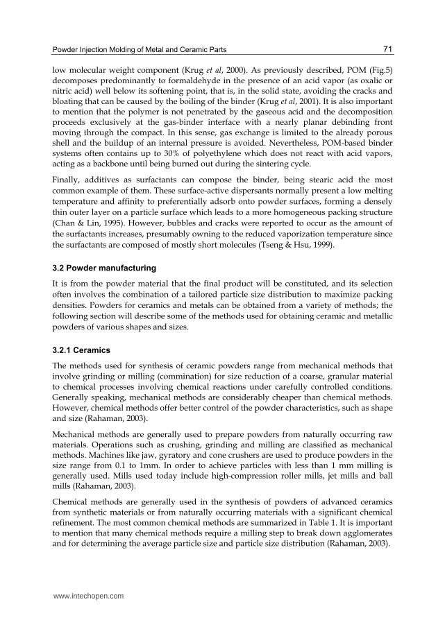
Powder Injection Molding of Metal and Ceramic Parts
71
low molecular weight component (Krug et al 2000) As previously described POM (Fig5) decomposes predominantly to formaldehyde in the presence of an acid vapor (as oxalic or nitric acid) well below its softening point that is in the solid state avoiding the cracks and bloating that can be caused by the boiling of the binder (Krug et al 2001) It is also important to mention that the polymer is not penetrated by the gaseous acid and the decomposition proceeds exclusively at the gas-binder interface with a nearly planar debinding front moving through the compact In this sense gas exchange is limited to the already porous shell and the buildup of an internal pressure is avoided Nevertheless POM-based binder systems often contains up to 30 of polyethylene which does not react with acid vapors acting as a backbone until being burned out during the sintering cycle
Finally additives as surfactants can compose the binder being stearic acid the most
common example of them These surface-active dispersants normally present a low melting
temperature and affinity to preferentially adsorb onto powder surfaces forming a densely
thin outer layer on a particle surface which leads to a more homogeneous packing structure
(Chan amp Lin 1995) However bubbles and cracks were reported to occur as the amount of
the surfactants increases presumably owning to the reduced vaporization temperature since
the surfactants are composed of mostly short molecules (Tseng amp Hsu 1999)
32 Powder manufacturing
It is from the powder material that the final product will be constituted and its selection
often involves the combination of a tailored particle size distribution to maximize packing
densities Powders for ceramics and metals can be obtained from a variety of methods the
following section will describe some of the methods used for obtaining ceramic and metallic
powders of various shapes and sizes
321 Ceramics
The methods used for synthesis of ceramic powders range from mechanical methods that involve grinding or milling (commination) for size reduction of a coarse granular material to chemical processes involving chemical reactions under carefully controlled conditions Generally speaking mechanical methods are considerably cheaper than chemical methods However chemical methods offer better control of the powder characteristics such as shape and size (Rahaman 2003)
Mechanical methods are generally used to prepare powders from naturally occurring raw materials Operations such as crushing grinding and milling are classified as mechanical methods Machines like jaw gyratory and cone crushers are used to produce powders in the size range from 01 to 1mm In order to achieve particles with less than 1 mm milling is generally used Mills used today include high-compression roller mills jet mills and ball mills (Rahaman 2003)
Chemical methods are generally used in the synthesis of powders of advanced ceramics from synthetic materials or from naturally occurring materials with a significant chemical refinement The most common chemical methods are summarized in Table 1 It is important to mention that many chemical methods require a milling step to break down agglomerates and for determining the average particle size and particle size distribution (Rahaman 2003)
wwwintechopencom
Some Critical Issues for Injection Molding
72
Method Advantages Disadvantages
Solid-state reactions - Decomposition
- Reactions between solids
Inexpensive simple equipment used
Agglomerated powders limited homogeneity for
multicomponent powders Liquid solutions
-Precipitation -Solvent vaporization
-Gel routes
Small particles chemical homogeneity high purity
composition control
Agglomerated powders poor for non-oxides expensive
Non-aqueous liquid reaction Small particles high purity Limited to non-oxides
Gas-solid reactions Inexpensive for large particle
sizes Low purity expensive for fine
powders
Gas-liquid reactions Small particles high purity Expensive limited
applicability
Reaction between gasses Small particles high purity
inexpensive for oxides Agglomerated powders expensive for non-oxides
Table 1 Commonly used chemical methods for manufacturing of ceramic powders (Rahaman 2003)
322 Metals
Most metal powders can be produced by comminution of the refined ore Milling and grinding are methods to produce powders of any degree of fineness from friable or malleable metals (eg titanium or steel) However not all particle sizes are sinterable in general particles have to be below 45 m Currently there is a tendency to use submicron and nanoparticles since a better packing density can be achieved their activation energy is higher and their sintering temperature is lower (Shearwood et al 2005) Nevertheless care must be taken when handling nano powders since they can be explosive or can easily oxidize therefore most of the time powder metallurgy utilizes particles in the 1 to 45 m range (Hartwig et al 1998) In particular for metal injection molding the mean particle size ranges from 5 to 15 m (Krug et al 2002) This type of size particles can generally be achieved in ball mills rotary mills planetary mills jet mills vibrating grinders stampers and crushers (Schrader et al 2000)
Nickel or iron can react with carbon monoxide to form metal carbonyls carbonyl vapors undergo decomposition by instantaneous mixing with a large volume of hot inert gas followed by quenching the aerosol formed by diluting and cooling Metal powders from carbonyls have high purity small and uniform grain size and particles that are dense and round (Neikov et al 2009 Schrader et al 2000) The most commonly used powders in todayrsquos MIM production are carbonyl powders Simple mixtures of iron and nickel carbonyl powders are the basis of powder mixtures for metal injection molding other metals included in these mixtures include heat treatable steels and stainless steels (Hartwig et al 1998)
Metals or alloys that may be homogeneously melted can also be atomized in a stream or air or an inert gas (often argon) Some metals are melted first and later injected through an orifice into the stream to later be dropped in water such process is called shotting Other metals like iron and stainless steel may be fused in an electric arc and refractory metals in a plasma arc For example titanium droplets freeze to powder after being thrown from the end of a rapidly rotating bar heated by a plasma arc in a helium atmosphere (Schrader et al
wwwintechopencom
Powder Injection Molding of Metal and Ceramic Parts
73
2000) Water atomization leads to irregular particles with a good yield of particles below 45 m Gas atomized powders leads to mostly spherical particles (Fig 6) but the yield of particles below 45 mm is limited (Hartwig et al 1998)
Fig 6 SEM micrograph of gas atomized stainless steel powder (Hartwig et al 1998)
Metal powder can also be electrolytically deposited under the right conditions The deposited material may have to be broken up and ground to achieve the desired fineness heated to be annealed drive off hydrogen sorted and blended Electrodeposited powders are among the purest powders available but they are pricier (Schrader et al 2000)
Other less common methods of manufacturing metallic powders include vapor condensation chemical decomposition ordinary machining impacting of chips and scrap and granulation by stirring vigorously during solidification (Schrader et al 2000) The most common methods applied for obtaining powders of different metals can be found in Table 2
Production method Used for
Chemical Tantalum tungsten Electro-chemical Copper iron nickel Thermo-chemical Carbonyl-iron nickel
Mechanical (comminution amp atomization) Steels titanium intermetallics
Table 2 Common production methods for metal injection molding powders (Hartwig et al 1998)
323 Submicron powders
With the growing demand for microparts (Fig7) to be used in consumer electronics automotive parts and in the biomedical field there is also a requirement to use powders with smaller particles and perform what is called micro-PIM It is generally accepted that the smallest feature of a part can only be ten times larger than the mean particle diameter thus in order to obtain microparts with good edge definition and shape retention submicron or nanoparticles need to be used Also submicron powders have an enhanced sintering activity which is beneficial for attainment of high-density bodies at lower sintering
wwwintechopencom
Some Critical Issues for Injection Molding
74
temperatures Such powders are still under development since there are many issues that need to be resolved
Fig 7 Ceramic microparts produced by PIM (Pioter et al 2001)
Submicron powders tend to be pyrophoric and therefore it is essential to avoid any oxidation
during handling One way to avoid oxidation is to handle submicron powders in a glove box
under argon inside this box powders are coated with a binder constituent in order to avoid
oxidation in the subsequent processing steps of feedstock compounding and injection molding
(Zauner 2006) Another issue that arises as the particle size decreases below 1 m is the greater
tendency for particle-particle interaction which results in agglomerates If many agglomerates
are present the final sintered part could have a non-uniform distribution of particles and little
benefit is achieved compared to coarse particles Therefore the use of submicron powders
requires special handling and mixing procedures in order to minimize detrimental effects due
to the presence of agglomerates (Rahaman 2003)
33 Desired properties of feedstock
A homogeneous distribution of powder particles and binder in feedstock is important as it helps to minimize segregation during the injection molding stage and later on to obtain isotropic shrinkage after debinding and sintering (Quinard et al 2009) Avoiding segregation of feedstock components is necessary to prevent visual defects excessive porosity warpage and cracks in the sintered part (Thornagel 2010) The technique used for mixing binder and powder can influence the homogeneity of feedstock materials As shown by Quinard et al (2009) using a twin-screw extruder yielded a better binder distribution However when using a z-blade mixer a better binder volume distribution around the powder particles was achieved that would lead to an isotropic shrinkage after sintering
Understanding which the desired properties are for a binder is a crucial step in the
optimization of PIM regarding both productivity and quality of the final product Only a
few authors have been working in this direction and not all of them agree in their
wwwintechopencom
Powder Injection Molding of Metal and Ceramic Parts
75
conclusions For example regarding the flow characteristics German (1990) highlighted the
importance of low viscosity at the molding temperature a characteristic stressed by Liu et al
(2001) as even more important in the case of micro moldings Ahn et al (2008) mentioned
that a high drop in viscosity at the high shear rates (shear-thinning behavior) is also a
desired property for cavity filling with less energy especially for complicated geometries
However stability of the mixture should be taken into account in order to avoid powder-
binder separation
The binder should also be strong and rigid after cooling and present small molecules to fit
between particles (German 1990) No agreement is found regarding the viscosity-
temperature dependence which is suggested to be the least as possible by German (1990)
but high by Thomas-Vielma et al (2007) Nevertheless Ahn et al (2009) shown that contrary
to the viscosity-shear rate dependence the viscosity-temperature dependence is more
influenced by the powder selection than the selection of the binder itself
High thermal conductivity low thermal expansion coefficient short chain length no
orientation low contact angle and good adhesion with powder capillary attraction of
particles and be chemically passive with respect to the powder are also desired properties
that should be taken into account when selecting binder components (German 1990)
Thomas-Vielma et al (2007) reported that defects as cracking (Fig 8) slumping and sagging
are partly related to the swelling of the binder component during solvent debinding a
problem that can be reduced by increasing the crystallinity of the polymer acting as a
backbone Besides this the decomposition of such polymer should be non-corrosive non-
toxic and having low ash content (German 1990)
(A) (B)
Fig 8 Appearance of (A) cracks and (B) transverse cracks after thermal debinding on alumina parts (Thomas-Vielma et al 2007)
As can be observed in this section the thermal and time-dependent properties of the
different components of the binder play an important role in the quality of the final product
Furthermore it also influences the choice of process parameters as injection pressure and
heating ramp determining the cost and the productivity of the process In this sense
understanding and improving the properties of this multi-component system or its single
components have a great importance to the optimization of the PIM technology
1
100 μm
1
100 μm
wwwintechopencom
Some Critical Issues for Injection Molding
76
34 Possible feedstock optimization
Rheological and time-dependant properties represent powerful tools for optimizing the PIM process The binderrsquos rheological properties (flowability) are important to determine the optimal binder formulation or selecting a proper additive It has been suggested in the literature that the viscosity of the binder should be less than 01 Pa s in order to provide the PIM feedstock with a viscosity below 1000 Pa s (German 1990) Having low viscosity allows for easy molding However it is generally known that low viscosity materials have also low mechanical properties when solidified Having low mechanical properties transforms into a ldquogreen partrdquo which is prone to deformation and breakage if not handle with care especially right after molding when the binder is still soft For this reason a compromise has to be made between the molten rheological properties and the solid mechanical properties of binder
Bimodality in the molecular mass distribution (Fig 9) of binders is still an issue that has not been extensively studied Nevertheless recent investigations have shown its potential to bring two main benefits to the process of PIM lower the viscosity of the feedstock in the molten state and maintaining the mechanical strength of the green part all of this without modifying the chemistry of the binder
Fig 9 Schematic representation of bimodal and monomodal molecular mass distribution in polymeric materials
It has been observed that bimodality in the molecular mass distribution improves the shear relaxation modulus (Emri amp von Bernstorff 2006) and the shear creep compliance (Kubyshkina et al 2011) of polyamide 6 in the solid state Based on those results Stringari et al (2011) studied the effect of bimodal molecular mass distribution in POM and it was shown that bimodality decreases viscosity without significantly affecting the mechanical properties (shear creep compliance) of the potential PIM binder The mechanisms for such behavior could be explained as follows The addition of small polymer chains through bimodality increases the flowability of the binder in the molten state since such small
wwwintechopencom
Powder Injection Molding of Metal and Ceramic Parts
77
molecules can act as internal lubricants for the larger molecules facilitating their movement However when in the solid state the smaller molecules could fit between the larger ones creating a closely packed structure that cannot be deformed as easily translating into improved mechanical properties
Once good flowability of the binder has been obtained it is important to check the flowability of the feedstock material The flowability of feedstock will not only depend on the viscosity of binder but also on the powder loading The optimal powder loading refers to a concentration of powder for which a compound exhibits good flow properties good dispersion and distribution and flow stability in the shear rates applied during injection molding (102 - 105 s-1) Rheological data represents an extremely useful tool to evaluate optimum powder loading The ratio of feedstockrsquos viscosity to binderrsquos viscosity known as the relative viscosity is an important parameter used to determine the maximum packing fraction for a particular powder-binder compound As the powder concentration reaches the maximum level the flow of feedstock material is restrained and a sharp increase in relative viscosity is observed (Hausnerovaacute 2011)
The maximum loading level in a feedstock material is dependent on the characteristics of the powders and how these particles are packed The packing behavior of particulate materials depends largely on their particle size shape and surface characteristics Packing behavior has been explained by model systems with closely defined size and shape distributions Even though real materials do not have a well-defined shape and size distribution the principles derived from models appear to work reasonably well Theoretical maximum packing has been studied for spherical smooth regular mono-sized particles which can readily move past another With these particles a maximum ordered packing fraction of 074 has been established from geometrical principles In order to increase the packing fraction of powders small particles to fill in the pores in the packed structure obtained from larger particles are used and then use even smaller particles to fill in the remaining pores and so on This approach is known as multimodal packing and much effort has been devoted to find the optimal particle size ratios that yield maximum packing fractions in the field of particulate composites (Rothon 2003) German (1990) has already pointed out that an ideal PIM powder should combine large and small particles in a tailored size distribution Hausnerovaacute et al (1999) showed that feedstock material containing particles with a monomodal particle size distribution exhibit higher viscosity compared to feedstock with bimodal powder The current explanation for this behavior is that the smaller particles fill the inter-particle voids created by large particles thereby releasing previously immobilized molten binder (Hausnerovaacute 2011)
4 Injection molding
The second step in the PIM process is molding the feedstock into the desired shape The most popular method is to use a reciprocating screw horizontal hydraulic or electric machine in which a screw stirs the feedstock inside the barrel while it is melting After melting the feedstock the screw acts as a plunger to generate the pressure to fill the die (Stevenson 2009) Conventional screw-type injection molding machines consist of a clamping unit injection unit and control system The clamping unit houses the mold which is generally comprised of two halves When the clamping unit is closed material can be injected into the mold when the clamping unit is open the molded part can be removed
wwwintechopencom
Some Critical Issues for Injection Molding
78
The injection unit consists of a screw a heating system and a nozzle The screw transports the material inside a barrel compresses it and removes any bubbles The heating system brings the material to an appropriate temperature for easy flow The nozzle is the conduct through which the heated feedstock is injected into the mold under pressure The control system of a modern injection molding machine includes hardware and software where the processing conditions are set and saved to ensure the reproducibility of previously employed production cycles (Arburg 2009)
Molding of the feedstock is comparable to the injection molding of plain thermoplastics and it has the following stages (Arburg 2009 German amp Bose 1997)
a The pelletized feedstock is placed in the hopper of the injection molding machine b The binder in the feedstock is melted by the heating system c The molten material is injected under high pressure (60 MPa or even more) into the
mold cavity which is mounted in the clamping unit The feedstock must have low enough viscosity that it can flow into the die cavity under pressure
d The mold remains closed while cooling channels in the die extract heat from the molten feedstock and solidify the polymer to preserve the molded shape
e After solidification of the binder the nozzle of the injection die is pulled away from the mold by moving the injection unit The clamping unit opens and the molded part is ejected by the ejector system of the machine
f The green part is removed from the mold Due to the fragile nature of most green parts the removal process is done by hand or by a robotic system in order to prevent shocks or impacts which could deform or even break the molded part
The shaping equipment used in PIM is the same as the one used for plastic injection molding Due to the size of molded parts injection molding machines used for PIM are in the lower range with clamp force typically less than 100 tons 18 to 25 mm screws and shot size of less than 30 cm3 (Stevenson 2009) However the main important difference when dealing with injection molding of any powdered part is that many of the components of the molding machine are subject to a more intense wear particularly screws non-return valves cylinders and molds (Rosato amp Rosato 1995)
Injection molding machines for processing of powdery materials are optimized with wear-resistant components through special hardening processes or utilization of alloys For example when dealing with stainless steel feedstock materials hardening with carbon nitride is recommended by feedstock manufacturers And when working with ceramic and hard metals boride cladding or carbide hard facing are recommended Since harder screws are more brittle lower torque limits during startup are used to prevent screw breakage in PIM The solid feedstock pellets cause the most abrasive wear in the feed section of the screw thus the feedstock should be melted as early as possible in the injection cycle (Stevenson 2009)
Screw geometry of PIM machine is adopted to lower the compression rate and extend the compression zone as compared to screws used for thermoplastics (Hausnerovaacute 2011) Compression ratios used in PIM tend to be in the lower range Ratios between 12 and 18 are considered acceptable and a ratio of 16 is considered to be optimal for the removal of air between granules It is also important to mention that when calculating the barrel capacity of the injection unit the barrel rating must be scaled up to take into account the higher density of the PIM feedstock (Stevenson 2009)
wwwintechopencom
Powder Injection Molding of Metal and Ceramic Parts
79
The injection molding step can create undesirable features such as gate and ejection pin marks which must be located in non-critical locations otherwise they must be removed after fabrication Other design limitations include gradual thickness changes minimized wall thickness round corners to reduce stress concentrations and risk of crack appearance and minimum undercuts on internal bores Whenever possible it is important to design PIM parts with one flat surface which allows the use of standard trays during sintering otherwise special trays are required (Hausnerovaacute 2011)
5 Debinding
Before sintering the organic binder must be removed without disrupting the molded powder particles this process is commonly referred as debinding Organic polymers have to be removed completely from the ldquogreen partrdquo since carbon residues can influence the sintering process and affect the quality of the final product negatively Moreover binder removal is one of the most critical steps in the PIM process since defects can be produced by inadequate debinding like bloating blistering surface cracking and large internal voids It has been shown that the rate of binder removal plays a main role in the defect production due to structural changes in capillaries inside the green part (Oliveira et al 2005)
The most commonly used debinding techniques include thermal solvent and catalytic However there also exist some experimental techniques such as plasma debiding (dos Santos et al 2004) The following sections have the aim to provide the reader with a description of the different debinding techniques showing their benefits and limitations
51 Thermal debinding
Thermal debinding utilizes the mechanisms of thermal degradation of organic binders which is based on the successive dissociation of polymers to produce light molecules that are later evaporated out of the surface of the molded part Since the thermal degradation process is different for different polymers then thermal debinding time is greatly influenced by the type of polymer used The binders developed in the original PIM process were a mixture of polyethylene or polypropylene a synthetic or natural wax and stearic acid Feedstock materials based on such binders can be removed thermally However it has been shown in the literature that POM and polybutyl-methacrylate (PBMA) have a much faster degradation than other polymers such as polypropylene (PP) and ethylene-vinyl-acetate (EVA) (Kankawa 1997) It should also be noted that the choice of atmosphere under which thermal debinding is performed influences the rate of binder removal and some characteristics of the final piece such as density carbon or oxygen content (Quinard et al 2009)
In general it can be said that thermal debinding is an inefficient process that can result in a poor etching of the piece surface if not properly controlled Additionally increasing the temperature too fast may produce an excessive increase of vapor pressure in the core of the molded piece leading to defects Consequently in order to reduce the risk of cracks or shape deformation low heating rates are generally used resulting in a long debinding time ranging from 10 to 60 h (dos Santos et al 2004) However thermal debinding is still selected due to its simplicity safety and respect for the environment as compared to solvent and catalytic binder removal (Quinard et al 2009)
wwwintechopencom
Some Critical Issues for Injection Molding
80
In order to increase the efficiency of the thermal debinding process a vacuum pump is used to continuously pull binder vapor away from the heated parts Initially the heating rate is typically 05 Cmin or less until a temperature of 100 C is reached this temperature is hold for approximately 4 h and later it is increased to 400 C using a heating rate close to 1 Cmin this temperature is maintained for 2 h During the entire process the pieces are constantly exposed to a gas flow in order to remove the binder vapors which are condensed and collected in a trap Finally when all the binder is removed the temperature is increased and the sintering process can begin This is one of the main advantages of vacuum debinding However the debinding process is still around 10 hours long since the main mechanisms of debinding is still thermal degradation (dos Santos et al 2004)
Another variant of the thermal debinding process includes the use of a wicking material (porous substrate) which is in contact with the ldquogreen partrdquo or compact In industrial practice the compact is buried in the wicking material and therefore the binder is removed from the compact in all directions (Somasundram et al 2008) A simplified model is shown in Fig 10 The porous substrate provides a medium for capillary flow as the binder viscosity decreases due to the increase of temperature Wicking thermal debinding is performed at temperatures where the binder melts therefore the binder can flow out of the component into the pores of the contacting substrate Wicking involves liquid extraction while other thermal process requires the binder to be in gaseous state and thus the temperatures are generally lower but the process is slower due to the slower transport of liquid compared to a gas (German amp Bose 1997)
Fig 10 Schematic cross-section of compact (green part) surrounded by wicking powder during thermal debinding (adapted from Somasundram et al 2008)
52 Solvent debinding
Solvent debinding is done by immersing the molded part in a gaseous (Fig 11) or liquid solvent such as ethanol hexane heptanes and acetone at low temperature typically 50 to 60 C (Torralba et al 2011) The solvent removes at least one of the binder components and produces an open porosity The next step in solvent debinding is binder burnout to remove the backbone of the binder that provides adequate shape retention up to the onset of sintering (dos Santos et al 2004 Aggarwal et al 2007) Binder backbone removal is generally done thermally between 200 and 600 degC in a pre-sintering step (Tandon 2008)
The effectiveness of solvent debinding is strongly related to the geometry of the ldquogreen partrdquo in particular to the surface to volume ratio since the solvent needs to penetrate the part Other factors that influence solvent debinding include temperature and porosity
wwwintechopencom
Powder Injection Molding of Metal and Ceramic Parts
81
Fig 11 Solvent vapor debing process (adapted from German amp Bose 1997)
evolution The temperature effect is related to an increase in interaction between soluble binders and solvents as temperature increases in other words temperature changes the solubility and diffusion coefficient of the binder (Oliveira et al 2005)
There is a tendency to try to use binders that are soluble in water since handling the aqueous solvent is much easier than handling organic solvents Good examples of water-soluble binders include polyethylene glycols polyethylene oxide polyvinyl alcohols starches and polyacrylamide All of these polymers have monomers containing oxygen and nitrogen that are hydrophilic The time to debind is a function of the powder material particle size part geometry water temperature water circulation and water volume relative to mass of the ldquogreen partrdquo All of these variables are interrelated with each other and must be optimized for a particular piece After debinding parts are usually dried in a forced air furnace at 65 to 75 C for at least three hours The drying step can be included as part of the sintering program Water can be regenerated after debinding by distillation and therefore a closed process water circuit can be used (Auzene amp Roberjot 2011)
Another type of solvent debinding is the use of a supercritical process When applying supercritical extraction the operative pressures of solvents such as carbon dioxide or propane are kept around 10 MPa and temperatures are less than 100 C The use of low temperatures results in slow diffusion of the binder to the surface of the green part resulting in long processing times Super critical debinding is not widely employed in commercial operations due to the long processing times and elevated cost of the necessary equipment which require high precision control in temperature and pressure (dos Santos et al 2004)
53 Catalytic debinding
Catalytic debinding can be used for binders that decompose into smaller molecules in the presence of a catalyst when exposed to the appropriate temperature The most common example is a binder based on POM sometimes also referred as polyacetal A commercial example of a feedstock with a POM based binder is Catamoldreg produced by BASF By using a catalyst the polymer at the surface of the ldquogreen partrdquo is cracked into monomers and evaporates As the monomers evaporate pores are created that expose the polymer beneath the surface and the depolymerization process continues deeper into the molded part Thus the debinding occurs from the outside inwards Shorter debinding times are achieved with the use
wwwintechopencom
Some Critical Issues for Injection Molding
82
of the catalytic process since the rate of diffusion of monomers is high due to the small size of their molecules (Clemens 2009) Furthermore the small molecules generated have a high vapor pressure which greatly minimizes the potential for capillary condensation and allows thick part sections to be debound (Krueger 1996)
Polyacetal-based binders depolymerizes catalytically under acidic conditions yielding
formaldehyde a direct solid to gas transition (Fig 12) Temperature and catalyst
concentration play a key role in determining the rate of debinding as well as the particle
size of the powder and geometry of the molded part This type of debinding is performed
below the melting temperature of POM generally between 110 and 150 C The use of these
relative low temperatures prevents the formation of a liquid phase and thus prevents
deformation of the ldquogreen partrdquo due to gravitational distortion or stress relaxation (Fu et al
2005) Also the internal gas pressure is low which minimizes the danger of crack formation
and propagation For POM 100 nitric acid (HNO3) is the most suitable catalyst Even
though nitric acid is a strongly oxidizing agent its anhydrous form does not react with most
of the commonly used metal powders (Krueger et al 1993)
Fig 12 Decomposition of POM in the presence of nitric acid
The debinding time depends on the quantity of catalysts and temperature used An increase
of these two factors can shorten the time of depolymerization However there are some
limitations as to how much temperature and catalyst content can be increased not only due
to possible damage to the molded part but also due to health concerns As previously
mentioned POM decomposes into formaldehyde which due to its toxicity has limitations in
the allowable quantity (01 kgh) and concentration (20 mgm3) that can be present in the
working environment (Goyer et al 2006) The exhaust from the debinding oven must be
treated in two steps to get rid of the toxic bi-product of the depolymerization of POM which
are nitrogen dioxide (NO2) and formaldehyde (CH2O) First the exhaust is burned in a
reducing atmosphere (no oxygen and rich in nitrogen) at a temperature of 600 C
transforming nitric dioxide into nitrogen gas (N2) The second step consists of burning in an
oxidizing atmosphere at 800 C to transform formaldehyde into water and carbon dioxide
(Torralba et al 2011) If properly treated the exhaust fumes coming out of the debinding
oven does not represent a health hazard
It is important to mention that binders based on POM usually have a backbone polymer which is not susceptible to catalytic debinding Such backbone polymer helps retain strength and shape stability in the ldquobrown partrdquo However sintering cannot begin in the presence of
this backbone polymer and thus a thermal treatment between 200 and 600 C is applied to the part prior to the start of the sintering process (Tandon 2008)
wwwintechopencom
Powder Injection Molding of Metal and Ceramic Parts
83
54 Comparison between debinding processes
The major differences advantages and disadvantages between the three types of debinding techniques are summarized in Table 3
Debinding Technique
Key Features Advantages Disadvantages
Thermal
Slowly heat green part to melting or degradation temperatures with a continuous sweep gas to remove binder
One-step process no need to handle product between debinding and sintering (unless wicking is used) Low cost installation Applicable to a wide range of binders
Soft binder allows warpage poor dimensional control and relatively slow process (up to 60 h) If a wick is used problems to separate part from it
Solvent
Green part is placed in a solvent in gaseous or liquid state to extract binder via dissolution
Component remains rigid without chemical reactions Lower temperatures minimize defects and distortions Faster than thermal debinding (around 6 h)
Solvent hazard chemical handling and environmental concern (unless water soluble binder is used) Expensive equipment if using supercritical extraction Drying before sintering required if using liquid solvent
Catalytic
Heat green part in atmosphere containing catalyst to depolymerize binder and sweep away monomers Binder goes from solid to gas
Rapid process (4 to 6h) that works well on thick and thin sections with excellent shape retention
Possible hazards with acid catalysts and decomposition products Exhaust products must be treated properly to prevent health and environmental hazards
Table 3 Comparison between three major debinding techniques
6 Sintering
The last step of the PIM process is sintering Sintering is one of the oldest human technologies originating in the prehistoric era with the firing of pottery After the 1940s sintering has been studied fundamentally and scientifically leading to remarkable developments in sintering science Nowadays sintering can be used for the fabrication of all kinds of parts including powder-metallurgical parts and bulk ceramic components (Kang 2005)
Sintering is a thermal treatment that transforms metallic or ceramic powders into bulk materials with improved mechanical strength that in most cases have residual porosity Sintering is performed at temperatures below the melting temperature of the major constituent in the metal or ceramic powder generally within 70 to 90 of the melting point (Lame et al 2003) The temperature inside the sintering furnace is high enough to start the recrystallization process of the metal or ceramic particles but low enough so that the particles remain unmelted At such temperatures the particles recrystallize into each other causing them to fuse together (Boljanovic 2010)
wwwintechopencom
Some Critical Issues for Injection Molding
84
During sintering solid-state atomic diffusion takes place followed by recrystallization and grain growth When the temperature exceeds one half to two thirds of the melting temperature of the powder material significant atomic diffusion occurs and some chemical changes may happen on the surface of the particles such as the vaporization of chemically bounded water As temperature keeps increasing thermolysis occurs which is a process that burns out the organic components such as remaining binder dispersant etc During sintering there is a great deal of particle movement and mass transport It has been identified that there are at least six different mechanisms for mass transfer involved in sintering which are surface diffusion evaporation-condensation grain boundary diffusion lattice diffusion viscous flow and plastic flow These mechanisms lead to growth of necks between particles and thus increase the strength of the consolidated powders However some mechanisms also lead to shrinkage (more than 10) and densification Surface diffusion is the mechanism that produces surface smoothing particle joining and pore rounding but not volume shrinkage If the material has high vapor pressure sublimation and vapor transport produce the same effects as surface diffusion Diffusion along the grain boundaries and through the lattice produces both neck growth and volume shrinkage Bulk viscous flow plays an important role in densification when a wetting liquid is present while plastic deformation is important when a mechanical pressure is applied (Kang 2007)
Fusing of the metallic particles during the sintering process has been observed using synchrotron microtomography as shown in the figures below for copper particles It is clearly observed that during sintering the particles get closer to each other as interparticle necks grow
and the porosity is reduced From room temperature (Fig 13A) to 1000 C (Fig 13B) there is no significant shrinkage but the neck formation causes small displacements and rotations of the particles that lead to a different particle packing As a result of this rearrangement some pores
decrease in size but others increase After sintering for 120 min at 1050 C the interparticle necks have grown up and it is harder to distinguish individual particles (Fig 13C) Finally (Fig 13D) after the part was sintered for an additional 100 min and cooled down to room temperature most pores have vanished but some large pores remain (Lame et al 2003)
Fig 13 Non-compacted copper particles at different stages of the sintering process (A) at room temperature before sintering (B) after heating to 1050 C from room temperature in 45
min (C) at 1050 C after 120 min of sintering and (D) after sintering for 220 min at 1050 C and cooling to room temperature in 15 min (Lame et al 2003)
Depending on the size of the part and the material used the sintering time can vary For small parts such as bushings the average time varies from 1 to 15 h For average-size ferrous parts the sintering time can be 3 h However tungsten parts can have a sintering time of up to 8 h In
wwwintechopencom
Powder Injection Molding of Metal and Ceramic Parts
85
order to harden sintered parts a controlled cooling rate must be carried out in a separate section of the sintering furnace Cooling is done in a protective atmosphere in order to prevent oxidation of sintered parts Dissociated ammonia and nitrogen-based atmospheres are commonly used however vacuum atmospheres are also used for stainless steel and tungsten parts for example The cooling rate is critical since the mechanical properties of the sintered parts is affected by the phase transformation of the material (Boljanovic 2010)
7 Conclusion ndash Closing remarks
PIM is a powerful process for the manufacturing of parts with complex geometry It combines the design benefits of thermoplastic injection molding and the efficiency of powder metallurgy Due to its capability is expected that PIM will growth in importance However the current state of the art does not allow for PIM to be widely used and therefore there is a need to optimize the process to increase its efficiency and productivity as well as the quality of the final parts For instance there is still room for improving the performance of binders as to obtain excellent flowability in the molten state while having high mechanical properties in the solid state Optimization can also be brought into the powder design as to obtain the most adequate particle size distribution and size ratios for multimodal powders Also it has been shown that using nanoparticles brings many benefits into the PIM process but handling procedures of these materials and their processing to avoid agglomeration is still far from optimal In summary PIM technology still offers a broad field of opportunities for improvement through applied research
8 References
Ahn S Park SJ Lee S Atre SV amp German RM (2009) Effect of powders and binders on material properties and molding parameters in iron and stainless steel powder injection molding process Powder Technology Vol193 No2 (July 2009) pp162-169 ISSN 0032-5910
Aggarwal G Smid I Park SJ amp German RM (2007) Development of niobium powder injection molding Part II Debinding and sintering International Journal of Refractory Metals amp Hard Materials Vol25 No3 (May 2007) pp 226-236 ISSN 0263-4368
Arburg (2009) Powder Injection Moulding (PIM) ndash Production of complex moulded parts from metal and ceramic Arburg GmbH + Co KG Lossburg Germany Available from httpwwwarburgdecomcommondownloadWEB_522785_en_GBpdf
Auzene D amp Roberjot S (2011) Investigation into water soluble binder systems for powder injection moulding Powder Injection Moulsding International Vol5 No 1 (March 2011) pp54-57 ISSN 1753-1497
Boljanovic V (2010) Powder metallurgy In Metal Shaping Processes Casting and Molding Particulate Processing Deformation Processes Metal Removal Industrial Press Inc ISBN 9780831 133801 New York USA pp 75-106
Chan TY amp Lin SL (1995) Effects of stearic acid on the injection molding of alumina Journal of the American Ceramic Society Vol78 No10 (October 1995) pp 2746-2752 ISSN 1551-2916
Clemens F (2009) Thermoplastic extrusion for ceramic bodies In Extrusion in Ceramics- Engineering Materials and Processes Handle F (Ed) Springer-Verlag ISBN 978-3540271000 Berlin Germany pp 295-311
wwwintechopencom
Some Critical Issues for Injection Molding
86
Chuankrerkkul N Messer PF amp Davies HA (2007) Powder injection moulding of cemented carbides Feedstock preparation and injection moulding Journal of Metals Materials and Minerals Vol17 No1 (May 2007) pp53-57 ISSN 0857-6149
Dos Santos MA Neivock MP Maliska AM Klein AN amp Muzart JLR (2004) Plasma debinding and pre-sintering of injected parts Material Research Vol7 No3 (JulySeptember 2004) pp505-511 ISSN 1516-1439
Emri I amp von Bernstorff BS (2006) The effect of molecular mass distribution on time-dependent behavior of polyamides Journal of Applied Mechanics Vol73 No5 (September 2006) pp752-757 ISSN 0021-8936
Fu G Loh NH Tor SB Tay BY Murakoshi Y amp Maeda R (2005) Injection molding debinding and sinterng of 316L stainless steel microstructures Applied Physics AVol 81 No3 (May2005) pp495-500 ISSN 0947-8396
German RM (1990) Powder Injection Moulding Metals Powder Industries Federation ISBN 0918404959 Princeton New Jersey USA
German RM (2008) PIM breaks the $1 bn barrier Metal Powder Report Vol63 No3 (March 2008) pp8-10 ISSN 0026-0657
German RM amp Bose A (1997) Injection Moulding of Metals and Ceramics Metals Powder Industries Federation ISBN 187895461X Princeton New Jersey USA
GIA (2011) Metal and Ceramic Injection Molding Global Industry Analysts Inc San Jose USA
Gonccedilalves AC (2001) Metallic powder injection molding using low pressure Journal of Materials Processing Technology Vol118 No1-3 (December 2001) pp193-198 ISSN 0924-0136
Goyer N Beacutegin D Beaudry C Bouchard M Carrier G Lavoueacute G Noisel N amp Geacuterin M (2006) Prevention guide- Formaldehyde in the work place Institute de reserche Robert-Sauveacute en santeacute et en seacutecuriteacute du travail (IRSST) Montreal Canada Accessed August 28 2011 Available from
httpwwwirsstqccamediadocumentsPubIRSSTRG-473pdf ISBN 9782896310692
Hartwig T Veltl G Petzoldt F Kunze H Scholl R amp Kieback B (1998) Powders for metal injection molding Journal of European Ceramic Society Vol18 No 9 (October 1998) pp1211-1216 ISSN 0955-2219
Hausnerovaacute B (2011) Powder injection moulding- An alternative processing method for automotive items In New Trends and Developments in Automotive System Engineering Chiaberge M (Ed) InTech ISBN 9789533075144 Rijeka Croatia pp129-145
Hausnerovaacute B Saha P amp Kubat J (1999) Capillary flow of hard-metal carbide powder compunds International Polymer Processing Vol14 No 3 (March 1999) pp254-260 ISSN 0930-777X
Kang L (2007) Ceramic Membranes for Separation and Reaction John Wiley and Sons ISBN 9780470014400 Chichester England 306 pages
Kang SJ (2005) Sintering Densification Grain Growth amp Microstructure Elsevier Butterworth-Heinemann ISBN 9780750663864 Oxford UK 265 pages
Kankawa Y (1997) Effects of polymer decomposition behavior on thermal debinding process in metal injection molding Materials and Manufacturing Processes Vol12 No 4 (April 1997) pp681-690 ISSN 1042-6914
Krueger D Bloemacher M amp Weinand D (1993) Rapid catalytic debindng MIM feedstock a new technology grows into a manufacturing process In Advances in
wwwintechopencom
Powder Injection Molding of Metal and Ceramic Parts
87
Powder Metallurgy and Particulate Materials Metal Powder Industries Federation Princeton New Jersey USA Vol 5 No2 pp 165-180 ISSN 1065-5824
Krueger DC (1996) Process for improving the debinding rate of ceramic and metal injection molded products US Patent 5531958
Krug S Evans JRG amp ter Matt JHH (2000) Residual stresses and cracking in large ceramic injection mouldings subjected to different solidification schedules Journal of the European Ceramic Society Vol20 No14-15 (December 2000) pp2535-2541 ISSN 0955-2219
Krug S Evans JRG amp ter Maat JHH (2001) Transient effects during catalytic binder removal in ceramic injection moulding Journal of the European Ceramic Society Vol21 No12 (October 2001) pp2275-2283 ISSN 0955-2219
Krug S Evans JRG amp ter Maat JHH (2002) Differential sintering in ceramic injection moulding particle orientation effects Journal of the European Ceramic Society Vol22 No 2 (February 2002) pp173-181 ISSN 0955-2219
Kubyshkina G Zupančič B Stukelj M Grošelj D Marion L amp Emri I (2011) The influence of different sterilization techniques on the time-dependent behavior of polyamides Journal of Biomaterials and Nanobitechnology (accepted for publication) ISSN 2158-7027
Lame O Bellet D Di Michiel M amp Bouvard D (2003) In situ microtomography investigation of metal powder compacts during sintering Nuclear Instruments and Methods in Physics Research B Vol200 (January 2003) pp287-294 ISSN 0168-583X
Liu ZY Loh NH Tor SB amp Khor KA (2003) Characterization of powder injection molding feedstock Materials Characterization Vol49 No 4 (November 2002) pp313-320 ISSN 1044-5803
Mathew BA amp Mastromatteo R (2003) MIM Focus- Metal injection moulding for automotive applications Metal Powder Report Vol58 No3 (March 2002) pp32-35 ISSN 0026-0657
Merz L Rath S Piotter V Ruprecht R Ritzhaupt-Kleissl J amp Haussel J (2002) Feedstock development for micro powder injection molding Microsystem Technologies Vol8 No 2-3 (March 2002) pp129-132 ISSN 0946-7076
Neikov OD Naboychenko S Gopienko VG amp Frishberg IV (2009) Handbook of Non-Ferrous Metal Powders Technologies and applications Elsevier ISBN 9781856174220 Amsterdam The Netherlands 634 pages
Oliveira RVB Soldi V Fredel MC amp Pires ATN (2005) Ceramic injection molding influence of specimen dimensions and temperature on solven debinding kinetics Journal of Materials Processing Technology Vol160 No2 (March 2005) pp213-220 ISSN 0924-0136
Pioter V Bauer W Benzler T amp Emde A (2001) Injection molding of components for microsystems Microsystem Technologies Vol7 No 3 (March 2001) pp99-102 ISSN 0946-7076
Quinard C Barriere T Gelin JC (2009) Development and property identification of 316L stainless steel feedstock for PIM and PIM Powder Technology Vol190 No1-2 (March 2009) pp123-128 ISSN 0032-5910
Rahaman MN (2003) Ceramic processing and sintering Marcel Dekker ISBN 9780824709884 Basel Switzerland pp 49-122
Rosato DV amp Rosato DV (1996) Specialized injection molding process In Injection Molding Handbook 2nd edition Chapman amp Hall GmbH ISBN 9780792386193 Weinheim Germany pp 1005-1058
wwwintechopencom
Some Critical Issues for Injection Molding
88
Rothon RN (2003) Particulate-Filled Polymer Composites 2nd edition Smithers Rapra Technology Limited ISBN 9781859573822 Shropshire United Kingdom pp 29-33
Ruprecht R Gietzelt T Muumlller K Piotter V amp Hauszligelt J (2002) Injection molding of microstructured components from plastics metals and ceramics Microsystem Technologies Vol8 No4-5 (May 2002) pp351-358 ISSN 0946-7076
Schrader GF Elshennawy AK amp Doyle LE (2000) Powder Metalurgy In Manufacturing Process and Materials Society of Manufacturing Engineers ISBN 0872635171 Dearborn Michigan USA pp 199-209
Shearwood C Fu YQ Yu L amp Khor KA (2005) Spark plasma sintering of TiNi nano-powder Scripta Materialia Vol52 No6 (March 2005) pp455-460 ISSN 1359-6462
Somasundram IM Cendrowicz A Wilson DI amp Johns ML (2008) Phenomenological study and modelling of wick debinding Chemical Engineering Science Vol63 No14 (July 2008) pp3802-3809 ISSN 0009-2509
Stevenson JF (2009) Powder Metal Injection Molding In Injection Molding ndash Technology and Fundamentals Kamal MR Isayev AI amp Liu SJ (Ed) Cal Hanser Verlag ISBN 978156904343 Munich Germany pp 309-340
Stringari G Zupančič B Kubyshkina G von Bernstorff B amp Emri I (2011) Time-dependant properties of bimodal POM ndash Application in powder injection molding Powder Technology Vol208 No 3 (April 2011) pp590-595 ISSN 0032-5910
Tandon R (2008) Metal injection moulding In Encyclopedia of Materials Science and Technology Buschow KHJ Cahn RW Flemings MC Ilscher B Kramer EJ Mahajan S amp Veyssiere P (Ed) Elsevier Science Ltd ISBN 9780080431529 Amsterdam The Netherlands pp5439-5442
Tay BY Loh NH Tor SB Ng FL Fu G amp Lu XH (2009) Characterisation of micro gears produced by micro powder injection moulding Powder Technology Vol188 No 3 (January 2009) pp179-182 ISSN 0032-5910
Thomas-Vielma P Cervera A Levenfeld B amp Vaacuterez A (2008) Production of alumina parts by powder injection molding with a binder system based on high density polyethylene Journal of the European Ceramic SocietyVol28 No 4 (October 2007) pp763-771 ISSN 0955-2219
Thornagel M (2010) PIM 2010- Simulating flow can help avoid mould mistakes Metal Powder Report Vol65 No3 (March-April 2010) pp 26-29 ISSN 0026-0657
Torralba JM Hidalgo J amp Jimenez-Morales A (2011) Powder injection moulding Processing of small parts of complex shape Proceedings of ICITampMPT 2011 8th International Conference on Industrial Tools and Material Processing Technologies pp 53-58 ISBN 9789616692021 Ljubljana Slovenia October 2-5 2011
Tseng JW amp Hsu CK (1999) Cracking defect and porosity evolution during thermal debinding in ceramic injection moldings Ceramics International Vol25 No 5 (July 1999) pp461-466 ISSN 0272-8842
Yang WW Yang KY amp Hon MH (2002) Effects of PEG molecular weights on rheological behavior of alumina injection molding feedstocks Materials Chemistry and Physics Vol78 No 2 (February 2002) pp416-424 ISSN 0254-0584
Zauner R (2006) Micro powder injection moulding Microelectronics Engineering Vol83 No 4-9 (April - September 2006) pp1442-1444 ISSN 0167-9317
wwwintechopencom
Some Critical Issues for Injection MoldingEdited by Dr Jian Wang
ISBN 978-953-51-0297-7Hard cover 270 pagesPublisher InTechPublished online 23 March 2012Published in print edition March 2012
InTech EuropeUniversity Campus STeP Ri Slavka Krautzeka 83A 51000 Rijeka Croatia Phone +385 (51) 770 447 Fax +385 (51) 686 166wwwintechopencom
InTech ChinaUnit 405 Office Block Hotel Equatorial Shanghai No65 Yan An Road (West) Shanghai 200040 China
Phone +86-21-62489820 Fax +86-21-62489821
This book is composed of different chapters which are related to the subject of injection molding and written byleading international academic experts in the field It contains introduction on polymer PVT measurements andtwo main application areas of polymer PVT data in injection molding optimization for injection moldingprocess Powder Injection Molding which comprises Ceramic Injection Molding and Metal Injection Moldingans some special techniques or applications in injection molding It provides some clear presentation ofinjection molding process and equipment to direct people in plastics manufacturing to solve problems andavoid costly errors With useful fundamental information for knowing and optimizing the injection moldingoperation the readers could gain some working knowledge of the injection molding
How to referenceIn order to correctly reference this scholarly work feel free to copy and paste the following
Joamiacuten Gonzaacutelez-Gutieacuterrez Gustavo Beulke Stringari and Igor Emri (2012) Powder Injection Molding of Metaland Ceramic Parts Some Critical Issues for Injection Molding Dr Jian Wang (Ed) ISBN 978-953-51-0297-7InTech Available from httpwwwintechopencombookssome-critical-issues-for-injection-moldingpowder-injection-molding-of-metal-and-ceramic-parts-
copy 2012 The Author(s) Licensee IntechOpen This is an open access articledistributed under the terms of the Creative Commons Attribution 30License which permits unrestricted use distribution and reproduction inany medium provided the original work is properly cited

Some Critical Issues for Injection Molding
72
Method Advantages Disadvantages
Solid-state reactions - Decomposition
- Reactions between solids
Inexpensive simple equipment used
Agglomerated powders limited homogeneity for
multicomponent powders Liquid solutions
-Precipitation -Solvent vaporization
-Gel routes
Small particles chemical homogeneity high purity
composition control
Agglomerated powders poor for non-oxides expensive
Non-aqueous liquid reaction Small particles high purity Limited to non-oxides
Gas-solid reactions Inexpensive for large particle
sizes Low purity expensive for fine
powders
Gas-liquid reactions Small particles high purity Expensive limited
applicability
Reaction between gasses Small particles high purity
inexpensive for oxides Agglomerated powders expensive for non-oxides
Table 1 Commonly used chemical methods for manufacturing of ceramic powders (Rahaman 2003)
322 Metals
Most metal powders can be produced by comminution of the refined ore Milling and grinding are methods to produce powders of any degree of fineness from friable or malleable metals (eg titanium or steel) However not all particle sizes are sinterable in general particles have to be below 45 m Currently there is a tendency to use submicron and nanoparticles since a better packing density can be achieved their activation energy is higher and their sintering temperature is lower (Shearwood et al 2005) Nevertheless care must be taken when handling nano powders since they can be explosive or can easily oxidize therefore most of the time powder metallurgy utilizes particles in the 1 to 45 m range (Hartwig et al 1998) In particular for metal injection molding the mean particle size ranges from 5 to 15 m (Krug et al 2002) This type of size particles can generally be achieved in ball mills rotary mills planetary mills jet mills vibrating grinders stampers and crushers (Schrader et al 2000)
Nickel or iron can react with carbon monoxide to form metal carbonyls carbonyl vapors undergo decomposition by instantaneous mixing with a large volume of hot inert gas followed by quenching the aerosol formed by diluting and cooling Metal powders from carbonyls have high purity small and uniform grain size and particles that are dense and round (Neikov et al 2009 Schrader et al 2000) The most commonly used powders in todayrsquos MIM production are carbonyl powders Simple mixtures of iron and nickel carbonyl powders are the basis of powder mixtures for metal injection molding other metals included in these mixtures include heat treatable steels and stainless steels (Hartwig et al 1998)
Metals or alloys that may be homogeneously melted can also be atomized in a stream or air or an inert gas (often argon) Some metals are melted first and later injected through an orifice into the stream to later be dropped in water such process is called shotting Other metals like iron and stainless steel may be fused in an electric arc and refractory metals in a plasma arc For example titanium droplets freeze to powder after being thrown from the end of a rapidly rotating bar heated by a plasma arc in a helium atmosphere (Schrader et al
wwwintechopencom
Powder Injection Molding of Metal and Ceramic Parts
73
2000) Water atomization leads to irregular particles with a good yield of particles below 45 m Gas atomized powders leads to mostly spherical particles (Fig 6) but the yield of particles below 45 mm is limited (Hartwig et al 1998)
Fig 6 SEM micrograph of gas atomized stainless steel powder (Hartwig et al 1998)
Metal powder can also be electrolytically deposited under the right conditions The deposited material may have to be broken up and ground to achieve the desired fineness heated to be annealed drive off hydrogen sorted and blended Electrodeposited powders are among the purest powders available but they are pricier (Schrader et al 2000)
Other less common methods of manufacturing metallic powders include vapor condensation chemical decomposition ordinary machining impacting of chips and scrap and granulation by stirring vigorously during solidification (Schrader et al 2000) The most common methods applied for obtaining powders of different metals can be found in Table 2
Production method Used for
Chemical Tantalum tungsten Electro-chemical Copper iron nickel Thermo-chemical Carbonyl-iron nickel
Mechanical (comminution amp atomization) Steels titanium intermetallics
Table 2 Common production methods for metal injection molding powders (Hartwig et al 1998)
323 Submicron powders
With the growing demand for microparts (Fig7) to be used in consumer electronics automotive parts and in the biomedical field there is also a requirement to use powders with smaller particles and perform what is called micro-PIM It is generally accepted that the smallest feature of a part can only be ten times larger than the mean particle diameter thus in order to obtain microparts with good edge definition and shape retention submicron or nanoparticles need to be used Also submicron powders have an enhanced sintering activity which is beneficial for attainment of high-density bodies at lower sintering
wwwintechopencom
Some Critical Issues for Injection Molding
74
temperatures Such powders are still under development since there are many issues that need to be resolved
Fig 7 Ceramic microparts produced by PIM (Pioter et al 2001)
Submicron powders tend to be pyrophoric and therefore it is essential to avoid any oxidation
during handling One way to avoid oxidation is to handle submicron powders in a glove box
under argon inside this box powders are coated with a binder constituent in order to avoid
oxidation in the subsequent processing steps of feedstock compounding and injection molding
(Zauner 2006) Another issue that arises as the particle size decreases below 1 m is the greater
tendency for particle-particle interaction which results in agglomerates If many agglomerates
are present the final sintered part could have a non-uniform distribution of particles and little
benefit is achieved compared to coarse particles Therefore the use of submicron powders
requires special handling and mixing procedures in order to minimize detrimental effects due
to the presence of agglomerates (Rahaman 2003)
33 Desired properties of feedstock
A homogeneous distribution of powder particles and binder in feedstock is important as it helps to minimize segregation during the injection molding stage and later on to obtain isotropic shrinkage after debinding and sintering (Quinard et al 2009) Avoiding segregation of feedstock components is necessary to prevent visual defects excessive porosity warpage and cracks in the sintered part (Thornagel 2010) The technique used for mixing binder and powder can influence the homogeneity of feedstock materials As shown by Quinard et al (2009) using a twin-screw extruder yielded a better binder distribution However when using a z-blade mixer a better binder volume distribution around the powder particles was achieved that would lead to an isotropic shrinkage after sintering
Understanding which the desired properties are for a binder is a crucial step in the
optimization of PIM regarding both productivity and quality of the final product Only a
few authors have been working in this direction and not all of them agree in their
wwwintechopencom
Powder Injection Molding of Metal and Ceramic Parts
75
conclusions For example regarding the flow characteristics German (1990) highlighted the
importance of low viscosity at the molding temperature a characteristic stressed by Liu et al
(2001) as even more important in the case of micro moldings Ahn et al (2008) mentioned
that a high drop in viscosity at the high shear rates (shear-thinning behavior) is also a
desired property for cavity filling with less energy especially for complicated geometries
However stability of the mixture should be taken into account in order to avoid powder-
binder separation
The binder should also be strong and rigid after cooling and present small molecules to fit
between particles (German 1990) No agreement is found regarding the viscosity-
temperature dependence which is suggested to be the least as possible by German (1990)
but high by Thomas-Vielma et al (2007) Nevertheless Ahn et al (2009) shown that contrary
to the viscosity-shear rate dependence the viscosity-temperature dependence is more
influenced by the powder selection than the selection of the binder itself
High thermal conductivity low thermal expansion coefficient short chain length no
orientation low contact angle and good adhesion with powder capillary attraction of
particles and be chemically passive with respect to the powder are also desired properties
that should be taken into account when selecting binder components (German 1990)
Thomas-Vielma et al (2007) reported that defects as cracking (Fig 8) slumping and sagging
are partly related to the swelling of the binder component during solvent debinding a
problem that can be reduced by increasing the crystallinity of the polymer acting as a
backbone Besides this the decomposition of such polymer should be non-corrosive non-
toxic and having low ash content (German 1990)
(A) (B)
Fig 8 Appearance of (A) cracks and (B) transverse cracks after thermal debinding on alumina parts (Thomas-Vielma et al 2007)
As can be observed in this section the thermal and time-dependent properties of the
different components of the binder play an important role in the quality of the final product
Furthermore it also influences the choice of process parameters as injection pressure and
heating ramp determining the cost and the productivity of the process In this sense
understanding and improving the properties of this multi-component system or its single
components have a great importance to the optimization of the PIM technology
1
100 μm
1
100 μm
wwwintechopencom
Some Critical Issues for Injection Molding
76
34 Possible feedstock optimization
Rheological and time-dependant properties represent powerful tools for optimizing the PIM process The binderrsquos rheological properties (flowability) are important to determine the optimal binder formulation or selecting a proper additive It has been suggested in the literature that the viscosity of the binder should be less than 01 Pa s in order to provide the PIM feedstock with a viscosity below 1000 Pa s (German 1990) Having low viscosity allows for easy molding However it is generally known that low viscosity materials have also low mechanical properties when solidified Having low mechanical properties transforms into a ldquogreen partrdquo which is prone to deformation and breakage if not handle with care especially right after molding when the binder is still soft For this reason a compromise has to be made between the molten rheological properties and the solid mechanical properties of binder
Bimodality in the molecular mass distribution (Fig 9) of binders is still an issue that has not been extensively studied Nevertheless recent investigations have shown its potential to bring two main benefits to the process of PIM lower the viscosity of the feedstock in the molten state and maintaining the mechanical strength of the green part all of this without modifying the chemistry of the binder
Fig 9 Schematic representation of bimodal and monomodal molecular mass distribution in polymeric materials
It has been observed that bimodality in the molecular mass distribution improves the shear relaxation modulus (Emri amp von Bernstorff 2006) and the shear creep compliance (Kubyshkina et al 2011) of polyamide 6 in the solid state Based on those results Stringari et al (2011) studied the effect of bimodal molecular mass distribution in POM and it was shown that bimodality decreases viscosity without significantly affecting the mechanical properties (shear creep compliance) of the potential PIM binder The mechanisms for such behavior could be explained as follows The addition of small polymer chains through bimodality increases the flowability of the binder in the molten state since such small
wwwintechopencom
Powder Injection Molding of Metal and Ceramic Parts
77
molecules can act as internal lubricants for the larger molecules facilitating their movement However when in the solid state the smaller molecules could fit between the larger ones creating a closely packed structure that cannot be deformed as easily translating into improved mechanical properties
Once good flowability of the binder has been obtained it is important to check the flowability of the feedstock material The flowability of feedstock will not only depend on the viscosity of binder but also on the powder loading The optimal powder loading refers to a concentration of powder for which a compound exhibits good flow properties good dispersion and distribution and flow stability in the shear rates applied during injection molding (102 - 105 s-1) Rheological data represents an extremely useful tool to evaluate optimum powder loading The ratio of feedstockrsquos viscosity to binderrsquos viscosity known as the relative viscosity is an important parameter used to determine the maximum packing fraction for a particular powder-binder compound As the powder concentration reaches the maximum level the flow of feedstock material is restrained and a sharp increase in relative viscosity is observed (Hausnerovaacute 2011)
The maximum loading level in a feedstock material is dependent on the characteristics of the powders and how these particles are packed The packing behavior of particulate materials depends largely on their particle size shape and surface characteristics Packing behavior has been explained by model systems with closely defined size and shape distributions Even though real materials do not have a well-defined shape and size distribution the principles derived from models appear to work reasonably well Theoretical maximum packing has been studied for spherical smooth regular mono-sized particles which can readily move past another With these particles a maximum ordered packing fraction of 074 has been established from geometrical principles In order to increase the packing fraction of powders small particles to fill in the pores in the packed structure obtained from larger particles are used and then use even smaller particles to fill in the remaining pores and so on This approach is known as multimodal packing and much effort has been devoted to find the optimal particle size ratios that yield maximum packing fractions in the field of particulate composites (Rothon 2003) German (1990) has already pointed out that an ideal PIM powder should combine large and small particles in a tailored size distribution Hausnerovaacute et al (1999) showed that feedstock material containing particles with a monomodal particle size distribution exhibit higher viscosity compared to feedstock with bimodal powder The current explanation for this behavior is that the smaller particles fill the inter-particle voids created by large particles thereby releasing previously immobilized molten binder (Hausnerovaacute 2011)
4 Injection molding
The second step in the PIM process is molding the feedstock into the desired shape The most popular method is to use a reciprocating screw horizontal hydraulic or electric machine in which a screw stirs the feedstock inside the barrel while it is melting After melting the feedstock the screw acts as a plunger to generate the pressure to fill the die (Stevenson 2009) Conventional screw-type injection molding machines consist of a clamping unit injection unit and control system The clamping unit houses the mold which is generally comprised of two halves When the clamping unit is closed material can be injected into the mold when the clamping unit is open the molded part can be removed
wwwintechopencom
Some Critical Issues for Injection Molding
78
The injection unit consists of a screw a heating system and a nozzle The screw transports the material inside a barrel compresses it and removes any bubbles The heating system brings the material to an appropriate temperature for easy flow The nozzle is the conduct through which the heated feedstock is injected into the mold under pressure The control system of a modern injection molding machine includes hardware and software where the processing conditions are set and saved to ensure the reproducibility of previously employed production cycles (Arburg 2009)
Molding of the feedstock is comparable to the injection molding of plain thermoplastics and it has the following stages (Arburg 2009 German amp Bose 1997)
a The pelletized feedstock is placed in the hopper of the injection molding machine b The binder in the feedstock is melted by the heating system c The molten material is injected under high pressure (60 MPa or even more) into the
mold cavity which is mounted in the clamping unit The feedstock must have low enough viscosity that it can flow into the die cavity under pressure
d The mold remains closed while cooling channels in the die extract heat from the molten feedstock and solidify the polymer to preserve the molded shape
e After solidification of the binder the nozzle of the injection die is pulled away from the mold by moving the injection unit The clamping unit opens and the molded part is ejected by the ejector system of the machine
f The green part is removed from the mold Due to the fragile nature of most green parts the removal process is done by hand or by a robotic system in order to prevent shocks or impacts which could deform or even break the molded part
The shaping equipment used in PIM is the same as the one used for plastic injection molding Due to the size of molded parts injection molding machines used for PIM are in the lower range with clamp force typically less than 100 tons 18 to 25 mm screws and shot size of less than 30 cm3 (Stevenson 2009) However the main important difference when dealing with injection molding of any powdered part is that many of the components of the molding machine are subject to a more intense wear particularly screws non-return valves cylinders and molds (Rosato amp Rosato 1995)
Injection molding machines for processing of powdery materials are optimized with wear-resistant components through special hardening processes or utilization of alloys For example when dealing with stainless steel feedstock materials hardening with carbon nitride is recommended by feedstock manufacturers And when working with ceramic and hard metals boride cladding or carbide hard facing are recommended Since harder screws are more brittle lower torque limits during startup are used to prevent screw breakage in PIM The solid feedstock pellets cause the most abrasive wear in the feed section of the screw thus the feedstock should be melted as early as possible in the injection cycle (Stevenson 2009)
Screw geometry of PIM machine is adopted to lower the compression rate and extend the compression zone as compared to screws used for thermoplastics (Hausnerovaacute 2011) Compression ratios used in PIM tend to be in the lower range Ratios between 12 and 18 are considered acceptable and a ratio of 16 is considered to be optimal for the removal of air between granules It is also important to mention that when calculating the barrel capacity of the injection unit the barrel rating must be scaled up to take into account the higher density of the PIM feedstock (Stevenson 2009)
wwwintechopencom
Powder Injection Molding of Metal and Ceramic Parts
79
The injection molding step can create undesirable features such as gate and ejection pin marks which must be located in non-critical locations otherwise they must be removed after fabrication Other design limitations include gradual thickness changes minimized wall thickness round corners to reduce stress concentrations and risk of crack appearance and minimum undercuts on internal bores Whenever possible it is important to design PIM parts with one flat surface which allows the use of standard trays during sintering otherwise special trays are required (Hausnerovaacute 2011)
5 Debinding
Before sintering the organic binder must be removed without disrupting the molded powder particles this process is commonly referred as debinding Organic polymers have to be removed completely from the ldquogreen partrdquo since carbon residues can influence the sintering process and affect the quality of the final product negatively Moreover binder removal is one of the most critical steps in the PIM process since defects can be produced by inadequate debinding like bloating blistering surface cracking and large internal voids It has been shown that the rate of binder removal plays a main role in the defect production due to structural changes in capillaries inside the green part (Oliveira et al 2005)
The most commonly used debinding techniques include thermal solvent and catalytic However there also exist some experimental techniques such as plasma debiding (dos Santos et al 2004) The following sections have the aim to provide the reader with a description of the different debinding techniques showing their benefits and limitations
51 Thermal debinding
Thermal debinding utilizes the mechanisms of thermal degradation of organic binders which is based on the successive dissociation of polymers to produce light molecules that are later evaporated out of the surface of the molded part Since the thermal degradation process is different for different polymers then thermal debinding time is greatly influenced by the type of polymer used The binders developed in the original PIM process were a mixture of polyethylene or polypropylene a synthetic or natural wax and stearic acid Feedstock materials based on such binders can be removed thermally However it has been shown in the literature that POM and polybutyl-methacrylate (PBMA) have a much faster degradation than other polymers such as polypropylene (PP) and ethylene-vinyl-acetate (EVA) (Kankawa 1997) It should also be noted that the choice of atmosphere under which thermal debinding is performed influences the rate of binder removal and some characteristics of the final piece such as density carbon or oxygen content (Quinard et al 2009)
In general it can be said that thermal debinding is an inefficient process that can result in a poor etching of the piece surface if not properly controlled Additionally increasing the temperature too fast may produce an excessive increase of vapor pressure in the core of the molded piece leading to defects Consequently in order to reduce the risk of cracks or shape deformation low heating rates are generally used resulting in a long debinding time ranging from 10 to 60 h (dos Santos et al 2004) However thermal debinding is still selected due to its simplicity safety and respect for the environment as compared to solvent and catalytic binder removal (Quinard et al 2009)
wwwintechopencom
Some Critical Issues for Injection Molding
80
In order to increase the efficiency of the thermal debinding process a vacuum pump is used to continuously pull binder vapor away from the heated parts Initially the heating rate is typically 05 Cmin or less until a temperature of 100 C is reached this temperature is hold for approximately 4 h and later it is increased to 400 C using a heating rate close to 1 Cmin this temperature is maintained for 2 h During the entire process the pieces are constantly exposed to a gas flow in order to remove the binder vapors which are condensed and collected in a trap Finally when all the binder is removed the temperature is increased and the sintering process can begin This is one of the main advantages of vacuum debinding However the debinding process is still around 10 hours long since the main mechanisms of debinding is still thermal degradation (dos Santos et al 2004)
Another variant of the thermal debinding process includes the use of a wicking material (porous substrate) which is in contact with the ldquogreen partrdquo or compact In industrial practice the compact is buried in the wicking material and therefore the binder is removed from the compact in all directions (Somasundram et al 2008) A simplified model is shown in Fig 10 The porous substrate provides a medium for capillary flow as the binder viscosity decreases due to the increase of temperature Wicking thermal debinding is performed at temperatures where the binder melts therefore the binder can flow out of the component into the pores of the contacting substrate Wicking involves liquid extraction while other thermal process requires the binder to be in gaseous state and thus the temperatures are generally lower but the process is slower due to the slower transport of liquid compared to a gas (German amp Bose 1997)
Fig 10 Schematic cross-section of compact (green part) surrounded by wicking powder during thermal debinding (adapted from Somasundram et al 2008)
52 Solvent debinding
Solvent debinding is done by immersing the molded part in a gaseous (Fig 11) or liquid solvent such as ethanol hexane heptanes and acetone at low temperature typically 50 to 60 C (Torralba et al 2011) The solvent removes at least one of the binder components and produces an open porosity The next step in solvent debinding is binder burnout to remove the backbone of the binder that provides adequate shape retention up to the onset of sintering (dos Santos et al 2004 Aggarwal et al 2007) Binder backbone removal is generally done thermally between 200 and 600 degC in a pre-sintering step (Tandon 2008)
The effectiveness of solvent debinding is strongly related to the geometry of the ldquogreen partrdquo in particular to the surface to volume ratio since the solvent needs to penetrate the part Other factors that influence solvent debinding include temperature and porosity
wwwintechopencom
Powder Injection Molding of Metal and Ceramic Parts
81
Fig 11 Solvent vapor debing process (adapted from German amp Bose 1997)
evolution The temperature effect is related to an increase in interaction between soluble binders and solvents as temperature increases in other words temperature changes the solubility and diffusion coefficient of the binder (Oliveira et al 2005)
There is a tendency to try to use binders that are soluble in water since handling the aqueous solvent is much easier than handling organic solvents Good examples of water-soluble binders include polyethylene glycols polyethylene oxide polyvinyl alcohols starches and polyacrylamide All of these polymers have monomers containing oxygen and nitrogen that are hydrophilic The time to debind is a function of the powder material particle size part geometry water temperature water circulation and water volume relative to mass of the ldquogreen partrdquo All of these variables are interrelated with each other and must be optimized for a particular piece After debinding parts are usually dried in a forced air furnace at 65 to 75 C for at least three hours The drying step can be included as part of the sintering program Water can be regenerated after debinding by distillation and therefore a closed process water circuit can be used (Auzene amp Roberjot 2011)
Another type of solvent debinding is the use of a supercritical process When applying supercritical extraction the operative pressures of solvents such as carbon dioxide or propane are kept around 10 MPa and temperatures are less than 100 C The use of low temperatures results in slow diffusion of the binder to the surface of the green part resulting in long processing times Super critical debinding is not widely employed in commercial operations due to the long processing times and elevated cost of the necessary equipment which require high precision control in temperature and pressure (dos Santos et al 2004)
53 Catalytic debinding
Catalytic debinding can be used for binders that decompose into smaller molecules in the presence of a catalyst when exposed to the appropriate temperature The most common example is a binder based on POM sometimes also referred as polyacetal A commercial example of a feedstock with a POM based binder is Catamoldreg produced by BASF By using a catalyst the polymer at the surface of the ldquogreen partrdquo is cracked into monomers and evaporates As the monomers evaporate pores are created that expose the polymer beneath the surface and the depolymerization process continues deeper into the molded part Thus the debinding occurs from the outside inwards Shorter debinding times are achieved with the use
wwwintechopencom
Some Critical Issues for Injection Molding
82
of the catalytic process since the rate of diffusion of monomers is high due to the small size of their molecules (Clemens 2009) Furthermore the small molecules generated have a high vapor pressure which greatly minimizes the potential for capillary condensation and allows thick part sections to be debound (Krueger 1996)
Polyacetal-based binders depolymerizes catalytically under acidic conditions yielding
formaldehyde a direct solid to gas transition (Fig 12) Temperature and catalyst
concentration play a key role in determining the rate of debinding as well as the particle
size of the powder and geometry of the molded part This type of debinding is performed
below the melting temperature of POM generally between 110 and 150 C The use of these
relative low temperatures prevents the formation of a liquid phase and thus prevents
deformation of the ldquogreen partrdquo due to gravitational distortion or stress relaxation (Fu et al
2005) Also the internal gas pressure is low which minimizes the danger of crack formation
and propagation For POM 100 nitric acid (HNO3) is the most suitable catalyst Even
though nitric acid is a strongly oxidizing agent its anhydrous form does not react with most
of the commonly used metal powders (Krueger et al 1993)
Fig 12 Decomposition of POM in the presence of nitric acid
The debinding time depends on the quantity of catalysts and temperature used An increase
of these two factors can shorten the time of depolymerization However there are some
limitations as to how much temperature and catalyst content can be increased not only due
to possible damage to the molded part but also due to health concerns As previously
mentioned POM decomposes into formaldehyde which due to its toxicity has limitations in
the allowable quantity (01 kgh) and concentration (20 mgm3) that can be present in the
working environment (Goyer et al 2006) The exhaust from the debinding oven must be
treated in two steps to get rid of the toxic bi-product of the depolymerization of POM which
are nitrogen dioxide (NO2) and formaldehyde (CH2O) First the exhaust is burned in a
reducing atmosphere (no oxygen and rich in nitrogen) at a temperature of 600 C
transforming nitric dioxide into nitrogen gas (N2) The second step consists of burning in an
oxidizing atmosphere at 800 C to transform formaldehyde into water and carbon dioxide
(Torralba et al 2011) If properly treated the exhaust fumes coming out of the debinding
oven does not represent a health hazard
It is important to mention that binders based on POM usually have a backbone polymer which is not susceptible to catalytic debinding Such backbone polymer helps retain strength and shape stability in the ldquobrown partrdquo However sintering cannot begin in the presence of
this backbone polymer and thus a thermal treatment between 200 and 600 C is applied to the part prior to the start of the sintering process (Tandon 2008)
wwwintechopencom
Powder Injection Molding of Metal and Ceramic Parts
83
54 Comparison between debinding processes
The major differences advantages and disadvantages between the three types of debinding techniques are summarized in Table 3
Debinding Technique
Key Features Advantages Disadvantages
Thermal
Slowly heat green part to melting or degradation temperatures with a continuous sweep gas to remove binder
One-step process no need to handle product between debinding and sintering (unless wicking is used) Low cost installation Applicable to a wide range of binders
Soft binder allows warpage poor dimensional control and relatively slow process (up to 60 h) If a wick is used problems to separate part from it
Solvent
Green part is placed in a solvent in gaseous or liquid state to extract binder via dissolution
Component remains rigid without chemical reactions Lower temperatures minimize defects and distortions Faster than thermal debinding (around 6 h)
Solvent hazard chemical handling and environmental concern (unless water soluble binder is used) Expensive equipment if using supercritical extraction Drying before sintering required if using liquid solvent
Catalytic
Heat green part in atmosphere containing catalyst to depolymerize binder and sweep away monomers Binder goes from solid to gas
Rapid process (4 to 6h) that works well on thick and thin sections with excellent shape retention
Possible hazards with acid catalysts and decomposition products Exhaust products must be treated properly to prevent health and environmental hazards
Table 3 Comparison between three major debinding techniques
6 Sintering
The last step of the PIM process is sintering Sintering is one of the oldest human technologies originating in the prehistoric era with the firing of pottery After the 1940s sintering has been studied fundamentally and scientifically leading to remarkable developments in sintering science Nowadays sintering can be used for the fabrication of all kinds of parts including powder-metallurgical parts and bulk ceramic components (Kang 2005)
Sintering is a thermal treatment that transforms metallic or ceramic powders into bulk materials with improved mechanical strength that in most cases have residual porosity Sintering is performed at temperatures below the melting temperature of the major constituent in the metal or ceramic powder generally within 70 to 90 of the melting point (Lame et al 2003) The temperature inside the sintering furnace is high enough to start the recrystallization process of the metal or ceramic particles but low enough so that the particles remain unmelted At such temperatures the particles recrystallize into each other causing them to fuse together (Boljanovic 2010)
wwwintechopencom
Some Critical Issues for Injection Molding
84
During sintering solid-state atomic diffusion takes place followed by recrystallization and grain growth When the temperature exceeds one half to two thirds of the melting temperature of the powder material significant atomic diffusion occurs and some chemical changes may happen on the surface of the particles such as the vaporization of chemically bounded water As temperature keeps increasing thermolysis occurs which is a process that burns out the organic components such as remaining binder dispersant etc During sintering there is a great deal of particle movement and mass transport It has been identified that there are at least six different mechanisms for mass transfer involved in sintering which are surface diffusion evaporation-condensation grain boundary diffusion lattice diffusion viscous flow and plastic flow These mechanisms lead to growth of necks between particles and thus increase the strength of the consolidated powders However some mechanisms also lead to shrinkage (more than 10) and densification Surface diffusion is the mechanism that produces surface smoothing particle joining and pore rounding but not volume shrinkage If the material has high vapor pressure sublimation and vapor transport produce the same effects as surface diffusion Diffusion along the grain boundaries and through the lattice produces both neck growth and volume shrinkage Bulk viscous flow plays an important role in densification when a wetting liquid is present while plastic deformation is important when a mechanical pressure is applied (Kang 2007)
Fusing of the metallic particles during the sintering process has been observed using synchrotron microtomography as shown in the figures below for copper particles It is clearly observed that during sintering the particles get closer to each other as interparticle necks grow
and the porosity is reduced From room temperature (Fig 13A) to 1000 C (Fig 13B) there is no significant shrinkage but the neck formation causes small displacements and rotations of the particles that lead to a different particle packing As a result of this rearrangement some pores
decrease in size but others increase After sintering for 120 min at 1050 C the interparticle necks have grown up and it is harder to distinguish individual particles (Fig 13C) Finally (Fig 13D) after the part was sintered for an additional 100 min and cooled down to room temperature most pores have vanished but some large pores remain (Lame et al 2003)
Fig 13 Non-compacted copper particles at different stages of the sintering process (A) at room temperature before sintering (B) after heating to 1050 C from room temperature in 45
min (C) at 1050 C after 120 min of sintering and (D) after sintering for 220 min at 1050 C and cooling to room temperature in 15 min (Lame et al 2003)
Depending on the size of the part and the material used the sintering time can vary For small parts such as bushings the average time varies from 1 to 15 h For average-size ferrous parts the sintering time can be 3 h However tungsten parts can have a sintering time of up to 8 h In
wwwintechopencom
Powder Injection Molding of Metal and Ceramic Parts
85
order to harden sintered parts a controlled cooling rate must be carried out in a separate section of the sintering furnace Cooling is done in a protective atmosphere in order to prevent oxidation of sintered parts Dissociated ammonia and nitrogen-based atmospheres are commonly used however vacuum atmospheres are also used for stainless steel and tungsten parts for example The cooling rate is critical since the mechanical properties of the sintered parts is affected by the phase transformation of the material (Boljanovic 2010)
7 Conclusion ndash Closing remarks
PIM is a powerful process for the manufacturing of parts with complex geometry It combines the design benefits of thermoplastic injection molding and the efficiency of powder metallurgy Due to its capability is expected that PIM will growth in importance However the current state of the art does not allow for PIM to be widely used and therefore there is a need to optimize the process to increase its efficiency and productivity as well as the quality of the final parts For instance there is still room for improving the performance of binders as to obtain excellent flowability in the molten state while having high mechanical properties in the solid state Optimization can also be brought into the powder design as to obtain the most adequate particle size distribution and size ratios for multimodal powders Also it has been shown that using nanoparticles brings many benefits into the PIM process but handling procedures of these materials and their processing to avoid agglomeration is still far from optimal In summary PIM technology still offers a broad field of opportunities for improvement through applied research
8 References
Ahn S Park SJ Lee S Atre SV amp German RM (2009) Effect of powders and binders on material properties and molding parameters in iron and stainless steel powder injection molding process Powder Technology Vol193 No2 (July 2009) pp162-169 ISSN 0032-5910
Aggarwal G Smid I Park SJ amp German RM (2007) Development of niobium powder injection molding Part II Debinding and sintering International Journal of Refractory Metals amp Hard Materials Vol25 No3 (May 2007) pp 226-236 ISSN 0263-4368
Arburg (2009) Powder Injection Moulding (PIM) ndash Production of complex moulded parts from metal and ceramic Arburg GmbH + Co KG Lossburg Germany Available from httpwwwarburgdecomcommondownloadWEB_522785_en_GBpdf
Auzene D amp Roberjot S (2011) Investigation into water soluble binder systems for powder injection moulding Powder Injection Moulsding International Vol5 No 1 (March 2011) pp54-57 ISSN 1753-1497
Boljanovic V (2010) Powder metallurgy In Metal Shaping Processes Casting and Molding Particulate Processing Deformation Processes Metal Removal Industrial Press Inc ISBN 9780831 133801 New York USA pp 75-106
Chan TY amp Lin SL (1995) Effects of stearic acid on the injection molding of alumina Journal of the American Ceramic Society Vol78 No10 (October 1995) pp 2746-2752 ISSN 1551-2916
Clemens F (2009) Thermoplastic extrusion for ceramic bodies In Extrusion in Ceramics- Engineering Materials and Processes Handle F (Ed) Springer-Verlag ISBN 978-3540271000 Berlin Germany pp 295-311
wwwintechopencom
Some Critical Issues for Injection Molding
86
Chuankrerkkul N Messer PF amp Davies HA (2007) Powder injection moulding of cemented carbides Feedstock preparation and injection moulding Journal of Metals Materials and Minerals Vol17 No1 (May 2007) pp53-57 ISSN 0857-6149
Dos Santos MA Neivock MP Maliska AM Klein AN amp Muzart JLR (2004) Plasma debinding and pre-sintering of injected parts Material Research Vol7 No3 (JulySeptember 2004) pp505-511 ISSN 1516-1439
Emri I amp von Bernstorff BS (2006) The effect of molecular mass distribution on time-dependent behavior of polyamides Journal of Applied Mechanics Vol73 No5 (September 2006) pp752-757 ISSN 0021-8936
Fu G Loh NH Tor SB Tay BY Murakoshi Y amp Maeda R (2005) Injection molding debinding and sinterng of 316L stainless steel microstructures Applied Physics AVol 81 No3 (May2005) pp495-500 ISSN 0947-8396
German RM (1990) Powder Injection Moulding Metals Powder Industries Federation ISBN 0918404959 Princeton New Jersey USA
German RM (2008) PIM breaks the $1 bn barrier Metal Powder Report Vol63 No3 (March 2008) pp8-10 ISSN 0026-0657
German RM amp Bose A (1997) Injection Moulding of Metals and Ceramics Metals Powder Industries Federation ISBN 187895461X Princeton New Jersey USA
GIA (2011) Metal and Ceramic Injection Molding Global Industry Analysts Inc San Jose USA
Gonccedilalves AC (2001) Metallic powder injection molding using low pressure Journal of Materials Processing Technology Vol118 No1-3 (December 2001) pp193-198 ISSN 0924-0136
Goyer N Beacutegin D Beaudry C Bouchard M Carrier G Lavoueacute G Noisel N amp Geacuterin M (2006) Prevention guide- Formaldehyde in the work place Institute de reserche Robert-Sauveacute en santeacute et en seacutecuriteacute du travail (IRSST) Montreal Canada Accessed August 28 2011 Available from
httpwwwirsstqccamediadocumentsPubIRSSTRG-473pdf ISBN 9782896310692
Hartwig T Veltl G Petzoldt F Kunze H Scholl R amp Kieback B (1998) Powders for metal injection molding Journal of European Ceramic Society Vol18 No 9 (October 1998) pp1211-1216 ISSN 0955-2219
Hausnerovaacute B (2011) Powder injection moulding- An alternative processing method for automotive items In New Trends and Developments in Automotive System Engineering Chiaberge M (Ed) InTech ISBN 9789533075144 Rijeka Croatia pp129-145
Hausnerovaacute B Saha P amp Kubat J (1999) Capillary flow of hard-metal carbide powder compunds International Polymer Processing Vol14 No 3 (March 1999) pp254-260 ISSN 0930-777X
Kang L (2007) Ceramic Membranes for Separation and Reaction John Wiley and Sons ISBN 9780470014400 Chichester England 306 pages
Kang SJ (2005) Sintering Densification Grain Growth amp Microstructure Elsevier Butterworth-Heinemann ISBN 9780750663864 Oxford UK 265 pages
Kankawa Y (1997) Effects of polymer decomposition behavior on thermal debinding process in metal injection molding Materials and Manufacturing Processes Vol12 No 4 (April 1997) pp681-690 ISSN 1042-6914
Krueger D Bloemacher M amp Weinand D (1993) Rapid catalytic debindng MIM feedstock a new technology grows into a manufacturing process In Advances in
wwwintechopencom
Powder Injection Molding of Metal and Ceramic Parts
87
Powder Metallurgy and Particulate Materials Metal Powder Industries Federation Princeton New Jersey USA Vol 5 No2 pp 165-180 ISSN 1065-5824
Krueger DC (1996) Process for improving the debinding rate of ceramic and metal injection molded products US Patent 5531958
Krug S Evans JRG amp ter Matt JHH (2000) Residual stresses and cracking in large ceramic injection mouldings subjected to different solidification schedules Journal of the European Ceramic Society Vol20 No14-15 (December 2000) pp2535-2541 ISSN 0955-2219
Krug S Evans JRG amp ter Maat JHH (2001) Transient effects during catalytic binder removal in ceramic injection moulding Journal of the European Ceramic Society Vol21 No12 (October 2001) pp2275-2283 ISSN 0955-2219
Krug S Evans JRG amp ter Maat JHH (2002) Differential sintering in ceramic injection moulding particle orientation effects Journal of the European Ceramic Society Vol22 No 2 (February 2002) pp173-181 ISSN 0955-2219
Kubyshkina G Zupančič B Stukelj M Grošelj D Marion L amp Emri I (2011) The influence of different sterilization techniques on the time-dependent behavior of polyamides Journal of Biomaterials and Nanobitechnology (accepted for publication) ISSN 2158-7027
Lame O Bellet D Di Michiel M amp Bouvard D (2003) In situ microtomography investigation of metal powder compacts during sintering Nuclear Instruments and Methods in Physics Research B Vol200 (January 2003) pp287-294 ISSN 0168-583X
Liu ZY Loh NH Tor SB amp Khor KA (2003) Characterization of powder injection molding feedstock Materials Characterization Vol49 No 4 (November 2002) pp313-320 ISSN 1044-5803
Mathew BA amp Mastromatteo R (2003) MIM Focus- Metal injection moulding for automotive applications Metal Powder Report Vol58 No3 (March 2002) pp32-35 ISSN 0026-0657
Merz L Rath S Piotter V Ruprecht R Ritzhaupt-Kleissl J amp Haussel J (2002) Feedstock development for micro powder injection molding Microsystem Technologies Vol8 No 2-3 (March 2002) pp129-132 ISSN 0946-7076
Neikov OD Naboychenko S Gopienko VG amp Frishberg IV (2009) Handbook of Non-Ferrous Metal Powders Technologies and applications Elsevier ISBN 9781856174220 Amsterdam The Netherlands 634 pages
Oliveira RVB Soldi V Fredel MC amp Pires ATN (2005) Ceramic injection molding influence of specimen dimensions and temperature on solven debinding kinetics Journal of Materials Processing Technology Vol160 No2 (March 2005) pp213-220 ISSN 0924-0136
Pioter V Bauer W Benzler T amp Emde A (2001) Injection molding of components for microsystems Microsystem Technologies Vol7 No 3 (March 2001) pp99-102 ISSN 0946-7076
Quinard C Barriere T Gelin JC (2009) Development and property identification of 316L stainless steel feedstock for PIM and PIM Powder Technology Vol190 No1-2 (March 2009) pp123-128 ISSN 0032-5910
Rahaman MN (2003) Ceramic processing and sintering Marcel Dekker ISBN 9780824709884 Basel Switzerland pp 49-122
Rosato DV amp Rosato DV (1996) Specialized injection molding process In Injection Molding Handbook 2nd edition Chapman amp Hall GmbH ISBN 9780792386193 Weinheim Germany pp 1005-1058
wwwintechopencom
Some Critical Issues for Injection Molding
88
Rothon RN (2003) Particulate-Filled Polymer Composites 2nd edition Smithers Rapra Technology Limited ISBN 9781859573822 Shropshire United Kingdom pp 29-33
Ruprecht R Gietzelt T Muumlller K Piotter V amp Hauszligelt J (2002) Injection molding of microstructured components from plastics metals and ceramics Microsystem Technologies Vol8 No4-5 (May 2002) pp351-358 ISSN 0946-7076
Schrader GF Elshennawy AK amp Doyle LE (2000) Powder Metalurgy In Manufacturing Process and Materials Society of Manufacturing Engineers ISBN 0872635171 Dearborn Michigan USA pp 199-209
Shearwood C Fu YQ Yu L amp Khor KA (2005) Spark plasma sintering of TiNi nano-powder Scripta Materialia Vol52 No6 (March 2005) pp455-460 ISSN 1359-6462
Somasundram IM Cendrowicz A Wilson DI amp Johns ML (2008) Phenomenological study and modelling of wick debinding Chemical Engineering Science Vol63 No14 (July 2008) pp3802-3809 ISSN 0009-2509
Stevenson JF (2009) Powder Metal Injection Molding In Injection Molding ndash Technology and Fundamentals Kamal MR Isayev AI amp Liu SJ (Ed) Cal Hanser Verlag ISBN 978156904343 Munich Germany pp 309-340
Stringari G Zupančič B Kubyshkina G von Bernstorff B amp Emri I (2011) Time-dependant properties of bimodal POM ndash Application in powder injection molding Powder Technology Vol208 No 3 (April 2011) pp590-595 ISSN 0032-5910
Tandon R (2008) Metal injection moulding In Encyclopedia of Materials Science and Technology Buschow KHJ Cahn RW Flemings MC Ilscher B Kramer EJ Mahajan S amp Veyssiere P (Ed) Elsevier Science Ltd ISBN 9780080431529 Amsterdam The Netherlands pp5439-5442
Tay BY Loh NH Tor SB Ng FL Fu G amp Lu XH (2009) Characterisation of micro gears produced by micro powder injection moulding Powder Technology Vol188 No 3 (January 2009) pp179-182 ISSN 0032-5910
Thomas-Vielma P Cervera A Levenfeld B amp Vaacuterez A (2008) Production of alumina parts by powder injection molding with a binder system based on high density polyethylene Journal of the European Ceramic SocietyVol28 No 4 (October 2007) pp763-771 ISSN 0955-2219
Thornagel M (2010) PIM 2010- Simulating flow can help avoid mould mistakes Metal Powder Report Vol65 No3 (March-April 2010) pp 26-29 ISSN 0026-0657
Torralba JM Hidalgo J amp Jimenez-Morales A (2011) Powder injection moulding Processing of small parts of complex shape Proceedings of ICITampMPT 2011 8th International Conference on Industrial Tools and Material Processing Technologies pp 53-58 ISBN 9789616692021 Ljubljana Slovenia October 2-5 2011
Tseng JW amp Hsu CK (1999) Cracking defect and porosity evolution during thermal debinding in ceramic injection moldings Ceramics International Vol25 No 5 (July 1999) pp461-466 ISSN 0272-8842
Yang WW Yang KY amp Hon MH (2002) Effects of PEG molecular weights on rheological behavior of alumina injection molding feedstocks Materials Chemistry and Physics Vol78 No 2 (February 2002) pp416-424 ISSN 0254-0584
Zauner R (2006) Micro powder injection moulding Microelectronics Engineering Vol83 No 4-9 (April - September 2006) pp1442-1444 ISSN 0167-9317
wwwintechopencom
Some Critical Issues for Injection MoldingEdited by Dr Jian Wang
ISBN 978-953-51-0297-7Hard cover 270 pagesPublisher InTechPublished online 23 March 2012Published in print edition March 2012
InTech EuropeUniversity Campus STeP Ri Slavka Krautzeka 83A 51000 Rijeka Croatia Phone +385 (51) 770 447 Fax +385 (51) 686 166wwwintechopencom
InTech ChinaUnit 405 Office Block Hotel Equatorial Shanghai No65 Yan An Road (West) Shanghai 200040 China
Phone +86-21-62489820 Fax +86-21-62489821
This book is composed of different chapters which are related to the subject of injection molding and written byleading international academic experts in the field It contains introduction on polymer PVT measurements andtwo main application areas of polymer PVT data in injection molding optimization for injection moldingprocess Powder Injection Molding which comprises Ceramic Injection Molding and Metal Injection Moldingans some special techniques or applications in injection molding It provides some clear presentation ofinjection molding process and equipment to direct people in plastics manufacturing to solve problems andavoid costly errors With useful fundamental information for knowing and optimizing the injection moldingoperation the readers could gain some working knowledge of the injection molding
How to referenceIn order to correctly reference this scholarly work feel free to copy and paste the following
Joamiacuten Gonzaacutelez-Gutieacuterrez Gustavo Beulke Stringari and Igor Emri (2012) Powder Injection Molding of Metaland Ceramic Parts Some Critical Issues for Injection Molding Dr Jian Wang (Ed) ISBN 978-953-51-0297-7InTech Available from httpwwwintechopencombookssome-critical-issues-for-injection-moldingpowder-injection-molding-of-metal-and-ceramic-parts-
copy 2012 The Author(s) Licensee IntechOpen This is an open access articledistributed under the terms of the Creative Commons Attribution 30License which permits unrestricted use distribution and reproduction inany medium provided the original work is properly cited

Powder Injection Molding of Metal and Ceramic Parts
73
2000) Water atomization leads to irregular particles with a good yield of particles below 45 m Gas atomized powders leads to mostly spherical particles (Fig 6) but the yield of particles below 45 mm is limited (Hartwig et al 1998)
Fig 6 SEM micrograph of gas atomized stainless steel powder (Hartwig et al 1998)
Metal powder can also be electrolytically deposited under the right conditions The deposited material may have to be broken up and ground to achieve the desired fineness heated to be annealed drive off hydrogen sorted and blended Electrodeposited powders are among the purest powders available but they are pricier (Schrader et al 2000)
Other less common methods of manufacturing metallic powders include vapor condensation chemical decomposition ordinary machining impacting of chips and scrap and granulation by stirring vigorously during solidification (Schrader et al 2000) The most common methods applied for obtaining powders of different metals can be found in Table 2
Production method Used for
Chemical Tantalum tungsten Electro-chemical Copper iron nickel Thermo-chemical Carbonyl-iron nickel
Mechanical (comminution amp atomization) Steels titanium intermetallics
Table 2 Common production methods for metal injection molding powders (Hartwig et al 1998)
323 Submicron powders
With the growing demand for microparts (Fig7) to be used in consumer electronics automotive parts and in the biomedical field there is also a requirement to use powders with smaller particles and perform what is called micro-PIM It is generally accepted that the smallest feature of a part can only be ten times larger than the mean particle diameter thus in order to obtain microparts with good edge definition and shape retention submicron or nanoparticles need to be used Also submicron powders have an enhanced sintering activity which is beneficial for attainment of high-density bodies at lower sintering
wwwintechopencom
Some Critical Issues for Injection Molding
74
temperatures Such powders are still under development since there are many issues that need to be resolved
Fig 7 Ceramic microparts produced by PIM (Pioter et al 2001)
Submicron powders tend to be pyrophoric and therefore it is essential to avoid any oxidation
during handling One way to avoid oxidation is to handle submicron powders in a glove box
under argon inside this box powders are coated with a binder constituent in order to avoid
oxidation in the subsequent processing steps of feedstock compounding and injection molding
(Zauner 2006) Another issue that arises as the particle size decreases below 1 m is the greater
tendency for particle-particle interaction which results in agglomerates If many agglomerates
are present the final sintered part could have a non-uniform distribution of particles and little
benefit is achieved compared to coarse particles Therefore the use of submicron powders
requires special handling and mixing procedures in order to minimize detrimental effects due
to the presence of agglomerates (Rahaman 2003)
33 Desired properties of feedstock
A homogeneous distribution of powder particles and binder in feedstock is important as it helps to minimize segregation during the injection molding stage and later on to obtain isotropic shrinkage after debinding and sintering (Quinard et al 2009) Avoiding segregation of feedstock components is necessary to prevent visual defects excessive porosity warpage and cracks in the sintered part (Thornagel 2010) The technique used for mixing binder and powder can influence the homogeneity of feedstock materials As shown by Quinard et al (2009) using a twin-screw extruder yielded a better binder distribution However when using a z-blade mixer a better binder volume distribution around the powder particles was achieved that would lead to an isotropic shrinkage after sintering
Understanding which the desired properties are for a binder is a crucial step in the
optimization of PIM regarding both productivity and quality of the final product Only a
few authors have been working in this direction and not all of them agree in their
wwwintechopencom
Powder Injection Molding of Metal and Ceramic Parts
75
conclusions For example regarding the flow characteristics German (1990) highlighted the
importance of low viscosity at the molding temperature a characteristic stressed by Liu et al
(2001) as even more important in the case of micro moldings Ahn et al (2008) mentioned
that a high drop in viscosity at the high shear rates (shear-thinning behavior) is also a
desired property for cavity filling with less energy especially for complicated geometries
However stability of the mixture should be taken into account in order to avoid powder-
binder separation
The binder should also be strong and rigid after cooling and present small molecules to fit
between particles (German 1990) No agreement is found regarding the viscosity-
temperature dependence which is suggested to be the least as possible by German (1990)
but high by Thomas-Vielma et al (2007) Nevertheless Ahn et al (2009) shown that contrary
to the viscosity-shear rate dependence the viscosity-temperature dependence is more
influenced by the powder selection than the selection of the binder itself
High thermal conductivity low thermal expansion coefficient short chain length no
orientation low contact angle and good adhesion with powder capillary attraction of
particles and be chemically passive with respect to the powder are also desired properties
that should be taken into account when selecting binder components (German 1990)
Thomas-Vielma et al (2007) reported that defects as cracking (Fig 8) slumping and sagging
are partly related to the swelling of the binder component during solvent debinding a
problem that can be reduced by increasing the crystallinity of the polymer acting as a
backbone Besides this the decomposition of such polymer should be non-corrosive non-
toxic and having low ash content (German 1990)
(A) (B)
Fig 8 Appearance of (A) cracks and (B) transverse cracks after thermal debinding on alumina parts (Thomas-Vielma et al 2007)
As can be observed in this section the thermal and time-dependent properties of the
different components of the binder play an important role in the quality of the final product
Furthermore it also influences the choice of process parameters as injection pressure and
heating ramp determining the cost and the productivity of the process In this sense
understanding and improving the properties of this multi-component system or its single
components have a great importance to the optimization of the PIM technology
1
100 μm
1
100 μm
wwwintechopencom
Some Critical Issues for Injection Molding
76
34 Possible feedstock optimization
Rheological and time-dependant properties represent powerful tools for optimizing the PIM process The binderrsquos rheological properties (flowability) are important to determine the optimal binder formulation or selecting a proper additive It has been suggested in the literature that the viscosity of the binder should be less than 01 Pa s in order to provide the PIM feedstock with a viscosity below 1000 Pa s (German 1990) Having low viscosity allows for easy molding However it is generally known that low viscosity materials have also low mechanical properties when solidified Having low mechanical properties transforms into a ldquogreen partrdquo which is prone to deformation and breakage if not handle with care especially right after molding when the binder is still soft For this reason a compromise has to be made between the molten rheological properties and the solid mechanical properties of binder
Bimodality in the molecular mass distribution (Fig 9) of binders is still an issue that has not been extensively studied Nevertheless recent investigations have shown its potential to bring two main benefits to the process of PIM lower the viscosity of the feedstock in the molten state and maintaining the mechanical strength of the green part all of this without modifying the chemistry of the binder
Fig 9 Schematic representation of bimodal and monomodal molecular mass distribution in polymeric materials
It has been observed that bimodality in the molecular mass distribution improves the shear relaxation modulus (Emri amp von Bernstorff 2006) and the shear creep compliance (Kubyshkina et al 2011) of polyamide 6 in the solid state Based on those results Stringari et al (2011) studied the effect of bimodal molecular mass distribution in POM and it was shown that bimodality decreases viscosity without significantly affecting the mechanical properties (shear creep compliance) of the potential PIM binder The mechanisms for such behavior could be explained as follows The addition of small polymer chains through bimodality increases the flowability of the binder in the molten state since such small
wwwintechopencom
Powder Injection Molding of Metal and Ceramic Parts
77
molecules can act as internal lubricants for the larger molecules facilitating their movement However when in the solid state the smaller molecules could fit between the larger ones creating a closely packed structure that cannot be deformed as easily translating into improved mechanical properties
Once good flowability of the binder has been obtained it is important to check the flowability of the feedstock material The flowability of feedstock will not only depend on the viscosity of binder but also on the powder loading The optimal powder loading refers to a concentration of powder for which a compound exhibits good flow properties good dispersion and distribution and flow stability in the shear rates applied during injection molding (102 - 105 s-1) Rheological data represents an extremely useful tool to evaluate optimum powder loading The ratio of feedstockrsquos viscosity to binderrsquos viscosity known as the relative viscosity is an important parameter used to determine the maximum packing fraction for a particular powder-binder compound As the powder concentration reaches the maximum level the flow of feedstock material is restrained and a sharp increase in relative viscosity is observed (Hausnerovaacute 2011)
The maximum loading level in a feedstock material is dependent on the characteristics of the powders and how these particles are packed The packing behavior of particulate materials depends largely on their particle size shape and surface characteristics Packing behavior has been explained by model systems with closely defined size and shape distributions Even though real materials do not have a well-defined shape and size distribution the principles derived from models appear to work reasonably well Theoretical maximum packing has been studied for spherical smooth regular mono-sized particles which can readily move past another With these particles a maximum ordered packing fraction of 074 has been established from geometrical principles In order to increase the packing fraction of powders small particles to fill in the pores in the packed structure obtained from larger particles are used and then use even smaller particles to fill in the remaining pores and so on This approach is known as multimodal packing and much effort has been devoted to find the optimal particle size ratios that yield maximum packing fractions in the field of particulate composites (Rothon 2003) German (1990) has already pointed out that an ideal PIM powder should combine large and small particles in a tailored size distribution Hausnerovaacute et al (1999) showed that feedstock material containing particles with a monomodal particle size distribution exhibit higher viscosity compared to feedstock with bimodal powder The current explanation for this behavior is that the smaller particles fill the inter-particle voids created by large particles thereby releasing previously immobilized molten binder (Hausnerovaacute 2011)
4 Injection molding
The second step in the PIM process is molding the feedstock into the desired shape The most popular method is to use a reciprocating screw horizontal hydraulic or electric machine in which a screw stirs the feedstock inside the barrel while it is melting After melting the feedstock the screw acts as a plunger to generate the pressure to fill the die (Stevenson 2009) Conventional screw-type injection molding machines consist of a clamping unit injection unit and control system The clamping unit houses the mold which is generally comprised of two halves When the clamping unit is closed material can be injected into the mold when the clamping unit is open the molded part can be removed
wwwintechopencom
Some Critical Issues for Injection Molding
78
The injection unit consists of a screw a heating system and a nozzle The screw transports the material inside a barrel compresses it and removes any bubbles The heating system brings the material to an appropriate temperature for easy flow The nozzle is the conduct through which the heated feedstock is injected into the mold under pressure The control system of a modern injection molding machine includes hardware and software where the processing conditions are set and saved to ensure the reproducibility of previously employed production cycles (Arburg 2009)
Molding of the feedstock is comparable to the injection molding of plain thermoplastics and it has the following stages (Arburg 2009 German amp Bose 1997)
a The pelletized feedstock is placed in the hopper of the injection molding machine b The binder in the feedstock is melted by the heating system c The molten material is injected under high pressure (60 MPa or even more) into the
mold cavity which is mounted in the clamping unit The feedstock must have low enough viscosity that it can flow into the die cavity under pressure
d The mold remains closed while cooling channels in the die extract heat from the molten feedstock and solidify the polymer to preserve the molded shape
e After solidification of the binder the nozzle of the injection die is pulled away from the mold by moving the injection unit The clamping unit opens and the molded part is ejected by the ejector system of the machine
f The green part is removed from the mold Due to the fragile nature of most green parts the removal process is done by hand or by a robotic system in order to prevent shocks or impacts which could deform or even break the molded part
The shaping equipment used in PIM is the same as the one used for plastic injection molding Due to the size of molded parts injection molding machines used for PIM are in the lower range with clamp force typically less than 100 tons 18 to 25 mm screws and shot size of less than 30 cm3 (Stevenson 2009) However the main important difference when dealing with injection molding of any powdered part is that many of the components of the molding machine are subject to a more intense wear particularly screws non-return valves cylinders and molds (Rosato amp Rosato 1995)
Injection molding machines for processing of powdery materials are optimized with wear-resistant components through special hardening processes or utilization of alloys For example when dealing with stainless steel feedstock materials hardening with carbon nitride is recommended by feedstock manufacturers And when working with ceramic and hard metals boride cladding or carbide hard facing are recommended Since harder screws are more brittle lower torque limits during startup are used to prevent screw breakage in PIM The solid feedstock pellets cause the most abrasive wear in the feed section of the screw thus the feedstock should be melted as early as possible in the injection cycle (Stevenson 2009)
Screw geometry of PIM machine is adopted to lower the compression rate and extend the compression zone as compared to screws used for thermoplastics (Hausnerovaacute 2011) Compression ratios used in PIM tend to be in the lower range Ratios between 12 and 18 are considered acceptable and a ratio of 16 is considered to be optimal for the removal of air between granules It is also important to mention that when calculating the barrel capacity of the injection unit the barrel rating must be scaled up to take into account the higher density of the PIM feedstock (Stevenson 2009)
wwwintechopencom
Powder Injection Molding of Metal and Ceramic Parts
79
The injection molding step can create undesirable features such as gate and ejection pin marks which must be located in non-critical locations otherwise they must be removed after fabrication Other design limitations include gradual thickness changes minimized wall thickness round corners to reduce stress concentrations and risk of crack appearance and minimum undercuts on internal bores Whenever possible it is important to design PIM parts with one flat surface which allows the use of standard trays during sintering otherwise special trays are required (Hausnerovaacute 2011)
5 Debinding
Before sintering the organic binder must be removed without disrupting the molded powder particles this process is commonly referred as debinding Organic polymers have to be removed completely from the ldquogreen partrdquo since carbon residues can influence the sintering process and affect the quality of the final product negatively Moreover binder removal is one of the most critical steps in the PIM process since defects can be produced by inadequate debinding like bloating blistering surface cracking and large internal voids It has been shown that the rate of binder removal plays a main role in the defect production due to structural changes in capillaries inside the green part (Oliveira et al 2005)
The most commonly used debinding techniques include thermal solvent and catalytic However there also exist some experimental techniques such as plasma debiding (dos Santos et al 2004) The following sections have the aim to provide the reader with a description of the different debinding techniques showing their benefits and limitations
51 Thermal debinding
Thermal debinding utilizes the mechanisms of thermal degradation of organic binders which is based on the successive dissociation of polymers to produce light molecules that are later evaporated out of the surface of the molded part Since the thermal degradation process is different for different polymers then thermal debinding time is greatly influenced by the type of polymer used The binders developed in the original PIM process were a mixture of polyethylene or polypropylene a synthetic or natural wax and stearic acid Feedstock materials based on such binders can be removed thermally However it has been shown in the literature that POM and polybutyl-methacrylate (PBMA) have a much faster degradation than other polymers such as polypropylene (PP) and ethylene-vinyl-acetate (EVA) (Kankawa 1997) It should also be noted that the choice of atmosphere under which thermal debinding is performed influences the rate of binder removal and some characteristics of the final piece such as density carbon or oxygen content (Quinard et al 2009)
In general it can be said that thermal debinding is an inefficient process that can result in a poor etching of the piece surface if not properly controlled Additionally increasing the temperature too fast may produce an excessive increase of vapor pressure in the core of the molded piece leading to defects Consequently in order to reduce the risk of cracks or shape deformation low heating rates are generally used resulting in a long debinding time ranging from 10 to 60 h (dos Santos et al 2004) However thermal debinding is still selected due to its simplicity safety and respect for the environment as compared to solvent and catalytic binder removal (Quinard et al 2009)
wwwintechopencom
Some Critical Issues for Injection Molding
80
In order to increase the efficiency of the thermal debinding process a vacuum pump is used to continuously pull binder vapor away from the heated parts Initially the heating rate is typically 05 Cmin or less until a temperature of 100 C is reached this temperature is hold for approximately 4 h and later it is increased to 400 C using a heating rate close to 1 Cmin this temperature is maintained for 2 h During the entire process the pieces are constantly exposed to a gas flow in order to remove the binder vapors which are condensed and collected in a trap Finally when all the binder is removed the temperature is increased and the sintering process can begin This is one of the main advantages of vacuum debinding However the debinding process is still around 10 hours long since the main mechanisms of debinding is still thermal degradation (dos Santos et al 2004)
Another variant of the thermal debinding process includes the use of a wicking material (porous substrate) which is in contact with the ldquogreen partrdquo or compact In industrial practice the compact is buried in the wicking material and therefore the binder is removed from the compact in all directions (Somasundram et al 2008) A simplified model is shown in Fig 10 The porous substrate provides a medium for capillary flow as the binder viscosity decreases due to the increase of temperature Wicking thermal debinding is performed at temperatures where the binder melts therefore the binder can flow out of the component into the pores of the contacting substrate Wicking involves liquid extraction while other thermal process requires the binder to be in gaseous state and thus the temperatures are generally lower but the process is slower due to the slower transport of liquid compared to a gas (German amp Bose 1997)
Fig 10 Schematic cross-section of compact (green part) surrounded by wicking powder during thermal debinding (adapted from Somasundram et al 2008)
52 Solvent debinding
Solvent debinding is done by immersing the molded part in a gaseous (Fig 11) or liquid solvent such as ethanol hexane heptanes and acetone at low temperature typically 50 to 60 C (Torralba et al 2011) The solvent removes at least one of the binder components and produces an open porosity The next step in solvent debinding is binder burnout to remove the backbone of the binder that provides adequate shape retention up to the onset of sintering (dos Santos et al 2004 Aggarwal et al 2007) Binder backbone removal is generally done thermally between 200 and 600 degC in a pre-sintering step (Tandon 2008)
The effectiveness of solvent debinding is strongly related to the geometry of the ldquogreen partrdquo in particular to the surface to volume ratio since the solvent needs to penetrate the part Other factors that influence solvent debinding include temperature and porosity
wwwintechopencom
Powder Injection Molding of Metal and Ceramic Parts
81
Fig 11 Solvent vapor debing process (adapted from German amp Bose 1997)
evolution The temperature effect is related to an increase in interaction between soluble binders and solvents as temperature increases in other words temperature changes the solubility and diffusion coefficient of the binder (Oliveira et al 2005)
There is a tendency to try to use binders that are soluble in water since handling the aqueous solvent is much easier than handling organic solvents Good examples of water-soluble binders include polyethylene glycols polyethylene oxide polyvinyl alcohols starches and polyacrylamide All of these polymers have monomers containing oxygen and nitrogen that are hydrophilic The time to debind is a function of the powder material particle size part geometry water temperature water circulation and water volume relative to mass of the ldquogreen partrdquo All of these variables are interrelated with each other and must be optimized for a particular piece After debinding parts are usually dried in a forced air furnace at 65 to 75 C for at least three hours The drying step can be included as part of the sintering program Water can be regenerated after debinding by distillation and therefore a closed process water circuit can be used (Auzene amp Roberjot 2011)
Another type of solvent debinding is the use of a supercritical process When applying supercritical extraction the operative pressures of solvents such as carbon dioxide or propane are kept around 10 MPa and temperatures are less than 100 C The use of low temperatures results in slow diffusion of the binder to the surface of the green part resulting in long processing times Super critical debinding is not widely employed in commercial operations due to the long processing times and elevated cost of the necessary equipment which require high precision control in temperature and pressure (dos Santos et al 2004)
53 Catalytic debinding
Catalytic debinding can be used for binders that decompose into smaller molecules in the presence of a catalyst when exposed to the appropriate temperature The most common example is a binder based on POM sometimes also referred as polyacetal A commercial example of a feedstock with a POM based binder is Catamoldreg produced by BASF By using a catalyst the polymer at the surface of the ldquogreen partrdquo is cracked into monomers and evaporates As the monomers evaporate pores are created that expose the polymer beneath the surface and the depolymerization process continues deeper into the molded part Thus the debinding occurs from the outside inwards Shorter debinding times are achieved with the use
wwwintechopencom
Some Critical Issues for Injection Molding
82
of the catalytic process since the rate of diffusion of monomers is high due to the small size of their molecules (Clemens 2009) Furthermore the small molecules generated have a high vapor pressure which greatly minimizes the potential for capillary condensation and allows thick part sections to be debound (Krueger 1996)
Polyacetal-based binders depolymerizes catalytically under acidic conditions yielding
formaldehyde a direct solid to gas transition (Fig 12) Temperature and catalyst
concentration play a key role in determining the rate of debinding as well as the particle
size of the powder and geometry of the molded part This type of debinding is performed
below the melting temperature of POM generally between 110 and 150 C The use of these
relative low temperatures prevents the formation of a liquid phase and thus prevents
deformation of the ldquogreen partrdquo due to gravitational distortion or stress relaxation (Fu et al
2005) Also the internal gas pressure is low which minimizes the danger of crack formation
and propagation For POM 100 nitric acid (HNO3) is the most suitable catalyst Even
though nitric acid is a strongly oxidizing agent its anhydrous form does not react with most
of the commonly used metal powders (Krueger et al 1993)
Fig 12 Decomposition of POM in the presence of nitric acid
The debinding time depends on the quantity of catalysts and temperature used An increase
of these two factors can shorten the time of depolymerization However there are some
limitations as to how much temperature and catalyst content can be increased not only due
to possible damage to the molded part but also due to health concerns As previously
mentioned POM decomposes into formaldehyde which due to its toxicity has limitations in
the allowable quantity (01 kgh) and concentration (20 mgm3) that can be present in the
working environment (Goyer et al 2006) The exhaust from the debinding oven must be
treated in two steps to get rid of the toxic bi-product of the depolymerization of POM which
are nitrogen dioxide (NO2) and formaldehyde (CH2O) First the exhaust is burned in a
reducing atmosphere (no oxygen and rich in nitrogen) at a temperature of 600 C
transforming nitric dioxide into nitrogen gas (N2) The second step consists of burning in an
oxidizing atmosphere at 800 C to transform formaldehyde into water and carbon dioxide
(Torralba et al 2011) If properly treated the exhaust fumes coming out of the debinding
oven does not represent a health hazard
It is important to mention that binders based on POM usually have a backbone polymer which is not susceptible to catalytic debinding Such backbone polymer helps retain strength and shape stability in the ldquobrown partrdquo However sintering cannot begin in the presence of
this backbone polymer and thus a thermal treatment between 200 and 600 C is applied to the part prior to the start of the sintering process (Tandon 2008)
wwwintechopencom
Powder Injection Molding of Metal and Ceramic Parts
83
54 Comparison between debinding processes
The major differences advantages and disadvantages between the three types of debinding techniques are summarized in Table 3
Debinding Technique
Key Features Advantages Disadvantages
Thermal
Slowly heat green part to melting or degradation temperatures with a continuous sweep gas to remove binder
One-step process no need to handle product between debinding and sintering (unless wicking is used) Low cost installation Applicable to a wide range of binders
Soft binder allows warpage poor dimensional control and relatively slow process (up to 60 h) If a wick is used problems to separate part from it
Solvent
Green part is placed in a solvent in gaseous or liquid state to extract binder via dissolution
Component remains rigid without chemical reactions Lower temperatures minimize defects and distortions Faster than thermal debinding (around 6 h)
Solvent hazard chemical handling and environmental concern (unless water soluble binder is used) Expensive equipment if using supercritical extraction Drying before sintering required if using liquid solvent
Catalytic
Heat green part in atmosphere containing catalyst to depolymerize binder and sweep away monomers Binder goes from solid to gas
Rapid process (4 to 6h) that works well on thick and thin sections with excellent shape retention
Possible hazards with acid catalysts and decomposition products Exhaust products must be treated properly to prevent health and environmental hazards
Table 3 Comparison between three major debinding techniques
6 Sintering
The last step of the PIM process is sintering Sintering is one of the oldest human technologies originating in the prehistoric era with the firing of pottery After the 1940s sintering has been studied fundamentally and scientifically leading to remarkable developments in sintering science Nowadays sintering can be used for the fabrication of all kinds of parts including powder-metallurgical parts and bulk ceramic components (Kang 2005)
Sintering is a thermal treatment that transforms metallic or ceramic powders into bulk materials with improved mechanical strength that in most cases have residual porosity Sintering is performed at temperatures below the melting temperature of the major constituent in the metal or ceramic powder generally within 70 to 90 of the melting point (Lame et al 2003) The temperature inside the sintering furnace is high enough to start the recrystallization process of the metal or ceramic particles but low enough so that the particles remain unmelted At such temperatures the particles recrystallize into each other causing them to fuse together (Boljanovic 2010)
wwwintechopencom
Some Critical Issues for Injection Molding
84
During sintering solid-state atomic diffusion takes place followed by recrystallization and grain growth When the temperature exceeds one half to two thirds of the melting temperature of the powder material significant atomic diffusion occurs and some chemical changes may happen on the surface of the particles such as the vaporization of chemically bounded water As temperature keeps increasing thermolysis occurs which is a process that burns out the organic components such as remaining binder dispersant etc During sintering there is a great deal of particle movement and mass transport It has been identified that there are at least six different mechanisms for mass transfer involved in sintering which are surface diffusion evaporation-condensation grain boundary diffusion lattice diffusion viscous flow and plastic flow These mechanisms lead to growth of necks between particles and thus increase the strength of the consolidated powders However some mechanisms also lead to shrinkage (more than 10) and densification Surface diffusion is the mechanism that produces surface smoothing particle joining and pore rounding but not volume shrinkage If the material has high vapor pressure sublimation and vapor transport produce the same effects as surface diffusion Diffusion along the grain boundaries and through the lattice produces both neck growth and volume shrinkage Bulk viscous flow plays an important role in densification when a wetting liquid is present while plastic deformation is important when a mechanical pressure is applied (Kang 2007)
Fusing of the metallic particles during the sintering process has been observed using synchrotron microtomography as shown in the figures below for copper particles It is clearly observed that during sintering the particles get closer to each other as interparticle necks grow
and the porosity is reduced From room temperature (Fig 13A) to 1000 C (Fig 13B) there is no significant shrinkage but the neck formation causes small displacements and rotations of the particles that lead to a different particle packing As a result of this rearrangement some pores
decrease in size but others increase After sintering for 120 min at 1050 C the interparticle necks have grown up and it is harder to distinguish individual particles (Fig 13C) Finally (Fig 13D) after the part was sintered for an additional 100 min and cooled down to room temperature most pores have vanished but some large pores remain (Lame et al 2003)
Fig 13 Non-compacted copper particles at different stages of the sintering process (A) at room temperature before sintering (B) after heating to 1050 C from room temperature in 45
min (C) at 1050 C after 120 min of sintering and (D) after sintering for 220 min at 1050 C and cooling to room temperature in 15 min (Lame et al 2003)
Depending on the size of the part and the material used the sintering time can vary For small parts such as bushings the average time varies from 1 to 15 h For average-size ferrous parts the sintering time can be 3 h However tungsten parts can have a sintering time of up to 8 h In
wwwintechopencom
Powder Injection Molding of Metal and Ceramic Parts
85
order to harden sintered parts a controlled cooling rate must be carried out in a separate section of the sintering furnace Cooling is done in a protective atmosphere in order to prevent oxidation of sintered parts Dissociated ammonia and nitrogen-based atmospheres are commonly used however vacuum atmospheres are also used for stainless steel and tungsten parts for example The cooling rate is critical since the mechanical properties of the sintered parts is affected by the phase transformation of the material (Boljanovic 2010)
7 Conclusion ndash Closing remarks
PIM is a powerful process for the manufacturing of parts with complex geometry It combines the design benefits of thermoplastic injection molding and the efficiency of powder metallurgy Due to its capability is expected that PIM will growth in importance However the current state of the art does not allow for PIM to be widely used and therefore there is a need to optimize the process to increase its efficiency and productivity as well as the quality of the final parts For instance there is still room for improving the performance of binders as to obtain excellent flowability in the molten state while having high mechanical properties in the solid state Optimization can also be brought into the powder design as to obtain the most adequate particle size distribution and size ratios for multimodal powders Also it has been shown that using nanoparticles brings many benefits into the PIM process but handling procedures of these materials and their processing to avoid agglomeration is still far from optimal In summary PIM technology still offers a broad field of opportunities for improvement through applied research
8 References
Ahn S Park SJ Lee S Atre SV amp German RM (2009) Effect of powders and binders on material properties and molding parameters in iron and stainless steel powder injection molding process Powder Technology Vol193 No2 (July 2009) pp162-169 ISSN 0032-5910
Aggarwal G Smid I Park SJ amp German RM (2007) Development of niobium powder injection molding Part II Debinding and sintering International Journal of Refractory Metals amp Hard Materials Vol25 No3 (May 2007) pp 226-236 ISSN 0263-4368
Arburg (2009) Powder Injection Moulding (PIM) ndash Production of complex moulded parts from metal and ceramic Arburg GmbH + Co KG Lossburg Germany Available from httpwwwarburgdecomcommondownloadWEB_522785_en_GBpdf
Auzene D amp Roberjot S (2011) Investigation into water soluble binder systems for powder injection moulding Powder Injection Moulsding International Vol5 No 1 (March 2011) pp54-57 ISSN 1753-1497
Boljanovic V (2010) Powder metallurgy In Metal Shaping Processes Casting and Molding Particulate Processing Deformation Processes Metal Removal Industrial Press Inc ISBN 9780831 133801 New York USA pp 75-106
Chan TY amp Lin SL (1995) Effects of stearic acid on the injection molding of alumina Journal of the American Ceramic Society Vol78 No10 (October 1995) pp 2746-2752 ISSN 1551-2916
Clemens F (2009) Thermoplastic extrusion for ceramic bodies In Extrusion in Ceramics- Engineering Materials and Processes Handle F (Ed) Springer-Verlag ISBN 978-3540271000 Berlin Germany pp 295-311
wwwintechopencom
Some Critical Issues for Injection Molding
86
Chuankrerkkul N Messer PF amp Davies HA (2007) Powder injection moulding of cemented carbides Feedstock preparation and injection moulding Journal of Metals Materials and Minerals Vol17 No1 (May 2007) pp53-57 ISSN 0857-6149
Dos Santos MA Neivock MP Maliska AM Klein AN amp Muzart JLR (2004) Plasma debinding and pre-sintering of injected parts Material Research Vol7 No3 (JulySeptember 2004) pp505-511 ISSN 1516-1439
Emri I amp von Bernstorff BS (2006) The effect of molecular mass distribution on time-dependent behavior of polyamides Journal of Applied Mechanics Vol73 No5 (September 2006) pp752-757 ISSN 0021-8936
Fu G Loh NH Tor SB Tay BY Murakoshi Y amp Maeda R (2005) Injection molding debinding and sinterng of 316L stainless steel microstructures Applied Physics AVol 81 No3 (May2005) pp495-500 ISSN 0947-8396
German RM (1990) Powder Injection Moulding Metals Powder Industries Federation ISBN 0918404959 Princeton New Jersey USA
German RM (2008) PIM breaks the $1 bn barrier Metal Powder Report Vol63 No3 (March 2008) pp8-10 ISSN 0026-0657
German RM amp Bose A (1997) Injection Moulding of Metals and Ceramics Metals Powder Industries Federation ISBN 187895461X Princeton New Jersey USA
GIA (2011) Metal and Ceramic Injection Molding Global Industry Analysts Inc San Jose USA
Gonccedilalves AC (2001) Metallic powder injection molding using low pressure Journal of Materials Processing Technology Vol118 No1-3 (December 2001) pp193-198 ISSN 0924-0136
Goyer N Beacutegin D Beaudry C Bouchard M Carrier G Lavoueacute G Noisel N amp Geacuterin M (2006) Prevention guide- Formaldehyde in the work place Institute de reserche Robert-Sauveacute en santeacute et en seacutecuriteacute du travail (IRSST) Montreal Canada Accessed August 28 2011 Available from
httpwwwirsstqccamediadocumentsPubIRSSTRG-473pdf ISBN 9782896310692
Hartwig T Veltl G Petzoldt F Kunze H Scholl R amp Kieback B (1998) Powders for metal injection molding Journal of European Ceramic Society Vol18 No 9 (October 1998) pp1211-1216 ISSN 0955-2219
Hausnerovaacute B (2011) Powder injection moulding- An alternative processing method for automotive items In New Trends and Developments in Automotive System Engineering Chiaberge M (Ed) InTech ISBN 9789533075144 Rijeka Croatia pp129-145
Hausnerovaacute B Saha P amp Kubat J (1999) Capillary flow of hard-metal carbide powder compunds International Polymer Processing Vol14 No 3 (March 1999) pp254-260 ISSN 0930-777X
Kang L (2007) Ceramic Membranes for Separation and Reaction John Wiley and Sons ISBN 9780470014400 Chichester England 306 pages
Kang SJ (2005) Sintering Densification Grain Growth amp Microstructure Elsevier Butterworth-Heinemann ISBN 9780750663864 Oxford UK 265 pages
Kankawa Y (1997) Effects of polymer decomposition behavior on thermal debinding process in metal injection molding Materials and Manufacturing Processes Vol12 No 4 (April 1997) pp681-690 ISSN 1042-6914
Krueger D Bloemacher M amp Weinand D (1993) Rapid catalytic debindng MIM feedstock a new technology grows into a manufacturing process In Advances in
wwwintechopencom
Powder Injection Molding of Metal and Ceramic Parts
87
Powder Metallurgy and Particulate Materials Metal Powder Industries Federation Princeton New Jersey USA Vol 5 No2 pp 165-180 ISSN 1065-5824
Krueger DC (1996) Process for improving the debinding rate of ceramic and metal injection molded products US Patent 5531958
Krug S Evans JRG amp ter Matt JHH (2000) Residual stresses and cracking in large ceramic injection mouldings subjected to different solidification schedules Journal of the European Ceramic Society Vol20 No14-15 (December 2000) pp2535-2541 ISSN 0955-2219
Krug S Evans JRG amp ter Maat JHH (2001) Transient effects during catalytic binder removal in ceramic injection moulding Journal of the European Ceramic Society Vol21 No12 (October 2001) pp2275-2283 ISSN 0955-2219
Krug S Evans JRG amp ter Maat JHH (2002) Differential sintering in ceramic injection moulding particle orientation effects Journal of the European Ceramic Society Vol22 No 2 (February 2002) pp173-181 ISSN 0955-2219
Kubyshkina G Zupančič B Stukelj M Grošelj D Marion L amp Emri I (2011) The influence of different sterilization techniques on the time-dependent behavior of polyamides Journal of Biomaterials and Nanobitechnology (accepted for publication) ISSN 2158-7027
Lame O Bellet D Di Michiel M amp Bouvard D (2003) In situ microtomography investigation of metal powder compacts during sintering Nuclear Instruments and Methods in Physics Research B Vol200 (January 2003) pp287-294 ISSN 0168-583X
Liu ZY Loh NH Tor SB amp Khor KA (2003) Characterization of powder injection molding feedstock Materials Characterization Vol49 No 4 (November 2002) pp313-320 ISSN 1044-5803
Mathew BA amp Mastromatteo R (2003) MIM Focus- Metal injection moulding for automotive applications Metal Powder Report Vol58 No3 (March 2002) pp32-35 ISSN 0026-0657
Merz L Rath S Piotter V Ruprecht R Ritzhaupt-Kleissl J amp Haussel J (2002) Feedstock development for micro powder injection molding Microsystem Technologies Vol8 No 2-3 (March 2002) pp129-132 ISSN 0946-7076
Neikov OD Naboychenko S Gopienko VG amp Frishberg IV (2009) Handbook of Non-Ferrous Metal Powders Technologies and applications Elsevier ISBN 9781856174220 Amsterdam The Netherlands 634 pages
Oliveira RVB Soldi V Fredel MC amp Pires ATN (2005) Ceramic injection molding influence of specimen dimensions and temperature on solven debinding kinetics Journal of Materials Processing Technology Vol160 No2 (March 2005) pp213-220 ISSN 0924-0136
Pioter V Bauer W Benzler T amp Emde A (2001) Injection molding of components for microsystems Microsystem Technologies Vol7 No 3 (March 2001) pp99-102 ISSN 0946-7076
Quinard C Barriere T Gelin JC (2009) Development and property identification of 316L stainless steel feedstock for PIM and PIM Powder Technology Vol190 No1-2 (March 2009) pp123-128 ISSN 0032-5910
Rahaman MN (2003) Ceramic processing and sintering Marcel Dekker ISBN 9780824709884 Basel Switzerland pp 49-122
Rosato DV amp Rosato DV (1996) Specialized injection molding process In Injection Molding Handbook 2nd edition Chapman amp Hall GmbH ISBN 9780792386193 Weinheim Germany pp 1005-1058
wwwintechopencom
Some Critical Issues for Injection Molding
88
Rothon RN (2003) Particulate-Filled Polymer Composites 2nd edition Smithers Rapra Technology Limited ISBN 9781859573822 Shropshire United Kingdom pp 29-33
Ruprecht R Gietzelt T Muumlller K Piotter V amp Hauszligelt J (2002) Injection molding of microstructured components from plastics metals and ceramics Microsystem Technologies Vol8 No4-5 (May 2002) pp351-358 ISSN 0946-7076
Schrader GF Elshennawy AK amp Doyle LE (2000) Powder Metalurgy In Manufacturing Process and Materials Society of Manufacturing Engineers ISBN 0872635171 Dearborn Michigan USA pp 199-209
Shearwood C Fu YQ Yu L amp Khor KA (2005) Spark plasma sintering of TiNi nano-powder Scripta Materialia Vol52 No6 (March 2005) pp455-460 ISSN 1359-6462
Somasundram IM Cendrowicz A Wilson DI amp Johns ML (2008) Phenomenological study and modelling of wick debinding Chemical Engineering Science Vol63 No14 (July 2008) pp3802-3809 ISSN 0009-2509
Stevenson JF (2009) Powder Metal Injection Molding In Injection Molding ndash Technology and Fundamentals Kamal MR Isayev AI amp Liu SJ (Ed) Cal Hanser Verlag ISBN 978156904343 Munich Germany pp 309-340
Stringari G Zupančič B Kubyshkina G von Bernstorff B amp Emri I (2011) Time-dependant properties of bimodal POM ndash Application in powder injection molding Powder Technology Vol208 No 3 (April 2011) pp590-595 ISSN 0032-5910
Tandon R (2008) Metal injection moulding In Encyclopedia of Materials Science and Technology Buschow KHJ Cahn RW Flemings MC Ilscher B Kramer EJ Mahajan S amp Veyssiere P (Ed) Elsevier Science Ltd ISBN 9780080431529 Amsterdam The Netherlands pp5439-5442
Tay BY Loh NH Tor SB Ng FL Fu G amp Lu XH (2009) Characterisation of micro gears produced by micro powder injection moulding Powder Technology Vol188 No 3 (January 2009) pp179-182 ISSN 0032-5910
Thomas-Vielma P Cervera A Levenfeld B amp Vaacuterez A (2008) Production of alumina parts by powder injection molding with a binder system based on high density polyethylene Journal of the European Ceramic SocietyVol28 No 4 (October 2007) pp763-771 ISSN 0955-2219
Thornagel M (2010) PIM 2010- Simulating flow can help avoid mould mistakes Metal Powder Report Vol65 No3 (March-April 2010) pp 26-29 ISSN 0026-0657
Torralba JM Hidalgo J amp Jimenez-Morales A (2011) Powder injection moulding Processing of small parts of complex shape Proceedings of ICITampMPT 2011 8th International Conference on Industrial Tools and Material Processing Technologies pp 53-58 ISBN 9789616692021 Ljubljana Slovenia October 2-5 2011
Tseng JW amp Hsu CK (1999) Cracking defect and porosity evolution during thermal debinding in ceramic injection moldings Ceramics International Vol25 No 5 (July 1999) pp461-466 ISSN 0272-8842
Yang WW Yang KY amp Hon MH (2002) Effects of PEG molecular weights on rheological behavior of alumina injection molding feedstocks Materials Chemistry and Physics Vol78 No 2 (February 2002) pp416-424 ISSN 0254-0584
Zauner R (2006) Micro powder injection moulding Microelectronics Engineering Vol83 No 4-9 (April - September 2006) pp1442-1444 ISSN 0167-9317
wwwintechopencom
Some Critical Issues for Injection MoldingEdited by Dr Jian Wang
ISBN 978-953-51-0297-7Hard cover 270 pagesPublisher InTechPublished online 23 March 2012Published in print edition March 2012
InTech EuropeUniversity Campus STeP Ri Slavka Krautzeka 83A 51000 Rijeka Croatia Phone +385 (51) 770 447 Fax +385 (51) 686 166wwwintechopencom
InTech ChinaUnit 405 Office Block Hotel Equatorial Shanghai No65 Yan An Road (West) Shanghai 200040 China
Phone +86-21-62489820 Fax +86-21-62489821
This book is composed of different chapters which are related to the subject of injection molding and written byleading international academic experts in the field It contains introduction on polymer PVT measurements andtwo main application areas of polymer PVT data in injection molding optimization for injection moldingprocess Powder Injection Molding which comprises Ceramic Injection Molding and Metal Injection Moldingans some special techniques or applications in injection molding It provides some clear presentation ofinjection molding process and equipment to direct people in plastics manufacturing to solve problems andavoid costly errors With useful fundamental information for knowing and optimizing the injection moldingoperation the readers could gain some working knowledge of the injection molding
How to referenceIn order to correctly reference this scholarly work feel free to copy and paste the following
Joamiacuten Gonzaacutelez-Gutieacuterrez Gustavo Beulke Stringari and Igor Emri (2012) Powder Injection Molding of Metaland Ceramic Parts Some Critical Issues for Injection Molding Dr Jian Wang (Ed) ISBN 978-953-51-0297-7InTech Available from httpwwwintechopencombookssome-critical-issues-for-injection-moldingpowder-injection-molding-of-metal-and-ceramic-parts-
copy 2012 The Author(s) Licensee IntechOpen This is an open access articledistributed under the terms of the Creative Commons Attribution 30License which permits unrestricted use distribution and reproduction inany medium provided the original work is properly cited
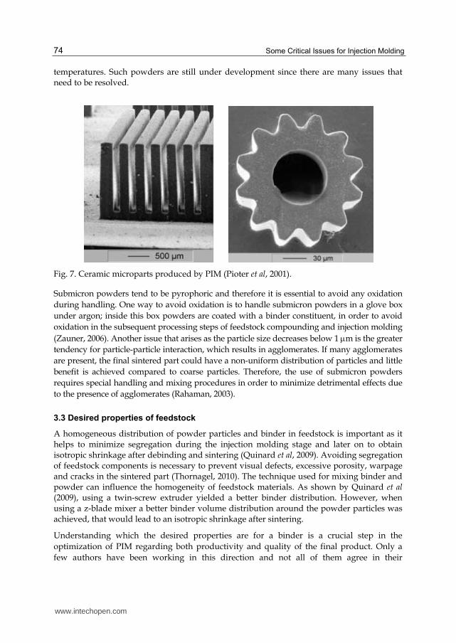
Some Critical Issues for Injection Molding
74
temperatures Such powders are still under development since there are many issues that need to be resolved
Fig 7 Ceramic microparts produced by PIM (Pioter et al 2001)
Submicron powders tend to be pyrophoric and therefore it is essential to avoid any oxidation
during handling One way to avoid oxidation is to handle submicron powders in a glove box
under argon inside this box powders are coated with a binder constituent in order to avoid
oxidation in the subsequent processing steps of feedstock compounding and injection molding
(Zauner 2006) Another issue that arises as the particle size decreases below 1 m is the greater
tendency for particle-particle interaction which results in agglomerates If many agglomerates
are present the final sintered part could have a non-uniform distribution of particles and little
benefit is achieved compared to coarse particles Therefore the use of submicron powders
requires special handling and mixing procedures in order to minimize detrimental effects due
to the presence of agglomerates (Rahaman 2003)
33 Desired properties of feedstock
A homogeneous distribution of powder particles and binder in feedstock is important as it helps to minimize segregation during the injection molding stage and later on to obtain isotropic shrinkage after debinding and sintering (Quinard et al 2009) Avoiding segregation of feedstock components is necessary to prevent visual defects excessive porosity warpage and cracks in the sintered part (Thornagel 2010) The technique used for mixing binder and powder can influence the homogeneity of feedstock materials As shown by Quinard et al (2009) using a twin-screw extruder yielded a better binder distribution However when using a z-blade mixer a better binder volume distribution around the powder particles was achieved that would lead to an isotropic shrinkage after sintering
Understanding which the desired properties are for a binder is a crucial step in the
optimization of PIM regarding both productivity and quality of the final product Only a
few authors have been working in this direction and not all of them agree in their
wwwintechopencom
Powder Injection Molding of Metal and Ceramic Parts
75
conclusions For example regarding the flow characteristics German (1990) highlighted the
importance of low viscosity at the molding temperature a characteristic stressed by Liu et al
(2001) as even more important in the case of micro moldings Ahn et al (2008) mentioned
that a high drop in viscosity at the high shear rates (shear-thinning behavior) is also a
desired property for cavity filling with less energy especially for complicated geometries
However stability of the mixture should be taken into account in order to avoid powder-
binder separation
The binder should also be strong and rigid after cooling and present small molecules to fit
between particles (German 1990) No agreement is found regarding the viscosity-
temperature dependence which is suggested to be the least as possible by German (1990)
but high by Thomas-Vielma et al (2007) Nevertheless Ahn et al (2009) shown that contrary
to the viscosity-shear rate dependence the viscosity-temperature dependence is more
influenced by the powder selection than the selection of the binder itself
High thermal conductivity low thermal expansion coefficient short chain length no
orientation low contact angle and good adhesion with powder capillary attraction of
particles and be chemically passive with respect to the powder are also desired properties
that should be taken into account when selecting binder components (German 1990)
Thomas-Vielma et al (2007) reported that defects as cracking (Fig 8) slumping and sagging
are partly related to the swelling of the binder component during solvent debinding a
problem that can be reduced by increasing the crystallinity of the polymer acting as a
backbone Besides this the decomposition of such polymer should be non-corrosive non-
toxic and having low ash content (German 1990)
(A) (B)
Fig 8 Appearance of (A) cracks and (B) transverse cracks after thermal debinding on alumina parts (Thomas-Vielma et al 2007)
As can be observed in this section the thermal and time-dependent properties of the
different components of the binder play an important role in the quality of the final product
Furthermore it also influences the choice of process parameters as injection pressure and
heating ramp determining the cost and the productivity of the process In this sense
understanding and improving the properties of this multi-component system or its single
components have a great importance to the optimization of the PIM technology
1
100 μm
1
100 μm
wwwintechopencom
Some Critical Issues for Injection Molding
76
34 Possible feedstock optimization
Rheological and time-dependant properties represent powerful tools for optimizing the PIM process The binderrsquos rheological properties (flowability) are important to determine the optimal binder formulation or selecting a proper additive It has been suggested in the literature that the viscosity of the binder should be less than 01 Pa s in order to provide the PIM feedstock with a viscosity below 1000 Pa s (German 1990) Having low viscosity allows for easy molding However it is generally known that low viscosity materials have also low mechanical properties when solidified Having low mechanical properties transforms into a ldquogreen partrdquo which is prone to deformation and breakage if not handle with care especially right after molding when the binder is still soft For this reason a compromise has to be made between the molten rheological properties and the solid mechanical properties of binder
Bimodality in the molecular mass distribution (Fig 9) of binders is still an issue that has not been extensively studied Nevertheless recent investigations have shown its potential to bring two main benefits to the process of PIM lower the viscosity of the feedstock in the molten state and maintaining the mechanical strength of the green part all of this without modifying the chemistry of the binder
Fig 9 Schematic representation of bimodal and monomodal molecular mass distribution in polymeric materials
It has been observed that bimodality in the molecular mass distribution improves the shear relaxation modulus (Emri amp von Bernstorff 2006) and the shear creep compliance (Kubyshkina et al 2011) of polyamide 6 in the solid state Based on those results Stringari et al (2011) studied the effect of bimodal molecular mass distribution in POM and it was shown that bimodality decreases viscosity without significantly affecting the mechanical properties (shear creep compliance) of the potential PIM binder The mechanisms for such behavior could be explained as follows The addition of small polymer chains through bimodality increases the flowability of the binder in the molten state since such small
wwwintechopencom
Powder Injection Molding of Metal and Ceramic Parts
77
molecules can act as internal lubricants for the larger molecules facilitating their movement However when in the solid state the smaller molecules could fit between the larger ones creating a closely packed structure that cannot be deformed as easily translating into improved mechanical properties
Once good flowability of the binder has been obtained it is important to check the flowability of the feedstock material The flowability of feedstock will not only depend on the viscosity of binder but also on the powder loading The optimal powder loading refers to a concentration of powder for which a compound exhibits good flow properties good dispersion and distribution and flow stability in the shear rates applied during injection molding (102 - 105 s-1) Rheological data represents an extremely useful tool to evaluate optimum powder loading The ratio of feedstockrsquos viscosity to binderrsquos viscosity known as the relative viscosity is an important parameter used to determine the maximum packing fraction for a particular powder-binder compound As the powder concentration reaches the maximum level the flow of feedstock material is restrained and a sharp increase in relative viscosity is observed (Hausnerovaacute 2011)
The maximum loading level in a feedstock material is dependent on the characteristics of the powders and how these particles are packed The packing behavior of particulate materials depends largely on their particle size shape and surface characteristics Packing behavior has been explained by model systems with closely defined size and shape distributions Even though real materials do not have a well-defined shape and size distribution the principles derived from models appear to work reasonably well Theoretical maximum packing has been studied for spherical smooth regular mono-sized particles which can readily move past another With these particles a maximum ordered packing fraction of 074 has been established from geometrical principles In order to increase the packing fraction of powders small particles to fill in the pores in the packed structure obtained from larger particles are used and then use even smaller particles to fill in the remaining pores and so on This approach is known as multimodal packing and much effort has been devoted to find the optimal particle size ratios that yield maximum packing fractions in the field of particulate composites (Rothon 2003) German (1990) has already pointed out that an ideal PIM powder should combine large and small particles in a tailored size distribution Hausnerovaacute et al (1999) showed that feedstock material containing particles with a monomodal particle size distribution exhibit higher viscosity compared to feedstock with bimodal powder The current explanation for this behavior is that the smaller particles fill the inter-particle voids created by large particles thereby releasing previously immobilized molten binder (Hausnerovaacute 2011)
4 Injection molding
The second step in the PIM process is molding the feedstock into the desired shape The most popular method is to use a reciprocating screw horizontal hydraulic or electric machine in which a screw stirs the feedstock inside the barrel while it is melting After melting the feedstock the screw acts as a plunger to generate the pressure to fill the die (Stevenson 2009) Conventional screw-type injection molding machines consist of a clamping unit injection unit and control system The clamping unit houses the mold which is generally comprised of two halves When the clamping unit is closed material can be injected into the mold when the clamping unit is open the molded part can be removed
wwwintechopencom
Some Critical Issues for Injection Molding
78
The injection unit consists of a screw a heating system and a nozzle The screw transports the material inside a barrel compresses it and removes any bubbles The heating system brings the material to an appropriate temperature for easy flow The nozzle is the conduct through which the heated feedstock is injected into the mold under pressure The control system of a modern injection molding machine includes hardware and software where the processing conditions are set and saved to ensure the reproducibility of previously employed production cycles (Arburg 2009)
Molding of the feedstock is comparable to the injection molding of plain thermoplastics and it has the following stages (Arburg 2009 German amp Bose 1997)
a The pelletized feedstock is placed in the hopper of the injection molding machine b The binder in the feedstock is melted by the heating system c The molten material is injected under high pressure (60 MPa or even more) into the
mold cavity which is mounted in the clamping unit The feedstock must have low enough viscosity that it can flow into the die cavity under pressure
d The mold remains closed while cooling channels in the die extract heat from the molten feedstock and solidify the polymer to preserve the molded shape
e After solidification of the binder the nozzle of the injection die is pulled away from the mold by moving the injection unit The clamping unit opens and the molded part is ejected by the ejector system of the machine
f The green part is removed from the mold Due to the fragile nature of most green parts the removal process is done by hand or by a robotic system in order to prevent shocks or impacts which could deform or even break the molded part
The shaping equipment used in PIM is the same as the one used for plastic injection molding Due to the size of molded parts injection molding machines used for PIM are in the lower range with clamp force typically less than 100 tons 18 to 25 mm screws and shot size of less than 30 cm3 (Stevenson 2009) However the main important difference when dealing with injection molding of any powdered part is that many of the components of the molding machine are subject to a more intense wear particularly screws non-return valves cylinders and molds (Rosato amp Rosato 1995)
Injection molding machines for processing of powdery materials are optimized with wear-resistant components through special hardening processes or utilization of alloys For example when dealing with stainless steel feedstock materials hardening with carbon nitride is recommended by feedstock manufacturers And when working with ceramic and hard metals boride cladding or carbide hard facing are recommended Since harder screws are more brittle lower torque limits during startup are used to prevent screw breakage in PIM The solid feedstock pellets cause the most abrasive wear in the feed section of the screw thus the feedstock should be melted as early as possible in the injection cycle (Stevenson 2009)
Screw geometry of PIM machine is adopted to lower the compression rate and extend the compression zone as compared to screws used for thermoplastics (Hausnerovaacute 2011) Compression ratios used in PIM tend to be in the lower range Ratios between 12 and 18 are considered acceptable and a ratio of 16 is considered to be optimal for the removal of air between granules It is also important to mention that when calculating the barrel capacity of the injection unit the barrel rating must be scaled up to take into account the higher density of the PIM feedstock (Stevenson 2009)
wwwintechopencom
Powder Injection Molding of Metal and Ceramic Parts
79
The injection molding step can create undesirable features such as gate and ejection pin marks which must be located in non-critical locations otherwise they must be removed after fabrication Other design limitations include gradual thickness changes minimized wall thickness round corners to reduce stress concentrations and risk of crack appearance and minimum undercuts on internal bores Whenever possible it is important to design PIM parts with one flat surface which allows the use of standard trays during sintering otherwise special trays are required (Hausnerovaacute 2011)
5 Debinding
Before sintering the organic binder must be removed without disrupting the molded powder particles this process is commonly referred as debinding Organic polymers have to be removed completely from the ldquogreen partrdquo since carbon residues can influence the sintering process and affect the quality of the final product negatively Moreover binder removal is one of the most critical steps in the PIM process since defects can be produced by inadequate debinding like bloating blistering surface cracking and large internal voids It has been shown that the rate of binder removal plays a main role in the defect production due to structural changes in capillaries inside the green part (Oliveira et al 2005)
The most commonly used debinding techniques include thermal solvent and catalytic However there also exist some experimental techniques such as plasma debiding (dos Santos et al 2004) The following sections have the aim to provide the reader with a description of the different debinding techniques showing their benefits and limitations
51 Thermal debinding
Thermal debinding utilizes the mechanisms of thermal degradation of organic binders which is based on the successive dissociation of polymers to produce light molecules that are later evaporated out of the surface of the molded part Since the thermal degradation process is different for different polymers then thermal debinding time is greatly influenced by the type of polymer used The binders developed in the original PIM process were a mixture of polyethylene or polypropylene a synthetic or natural wax and stearic acid Feedstock materials based on such binders can be removed thermally However it has been shown in the literature that POM and polybutyl-methacrylate (PBMA) have a much faster degradation than other polymers such as polypropylene (PP) and ethylene-vinyl-acetate (EVA) (Kankawa 1997) It should also be noted that the choice of atmosphere under which thermal debinding is performed influences the rate of binder removal and some characteristics of the final piece such as density carbon or oxygen content (Quinard et al 2009)
In general it can be said that thermal debinding is an inefficient process that can result in a poor etching of the piece surface if not properly controlled Additionally increasing the temperature too fast may produce an excessive increase of vapor pressure in the core of the molded piece leading to defects Consequently in order to reduce the risk of cracks or shape deformation low heating rates are generally used resulting in a long debinding time ranging from 10 to 60 h (dos Santos et al 2004) However thermal debinding is still selected due to its simplicity safety and respect for the environment as compared to solvent and catalytic binder removal (Quinard et al 2009)
wwwintechopencom
Some Critical Issues for Injection Molding
80
In order to increase the efficiency of the thermal debinding process a vacuum pump is used to continuously pull binder vapor away from the heated parts Initially the heating rate is typically 05 Cmin or less until a temperature of 100 C is reached this temperature is hold for approximately 4 h and later it is increased to 400 C using a heating rate close to 1 Cmin this temperature is maintained for 2 h During the entire process the pieces are constantly exposed to a gas flow in order to remove the binder vapors which are condensed and collected in a trap Finally when all the binder is removed the temperature is increased and the sintering process can begin This is one of the main advantages of vacuum debinding However the debinding process is still around 10 hours long since the main mechanisms of debinding is still thermal degradation (dos Santos et al 2004)
Another variant of the thermal debinding process includes the use of a wicking material (porous substrate) which is in contact with the ldquogreen partrdquo or compact In industrial practice the compact is buried in the wicking material and therefore the binder is removed from the compact in all directions (Somasundram et al 2008) A simplified model is shown in Fig 10 The porous substrate provides a medium for capillary flow as the binder viscosity decreases due to the increase of temperature Wicking thermal debinding is performed at temperatures where the binder melts therefore the binder can flow out of the component into the pores of the contacting substrate Wicking involves liquid extraction while other thermal process requires the binder to be in gaseous state and thus the temperatures are generally lower but the process is slower due to the slower transport of liquid compared to a gas (German amp Bose 1997)
Fig 10 Schematic cross-section of compact (green part) surrounded by wicking powder during thermal debinding (adapted from Somasundram et al 2008)
52 Solvent debinding
Solvent debinding is done by immersing the molded part in a gaseous (Fig 11) or liquid solvent such as ethanol hexane heptanes and acetone at low temperature typically 50 to 60 C (Torralba et al 2011) The solvent removes at least one of the binder components and produces an open porosity The next step in solvent debinding is binder burnout to remove the backbone of the binder that provides adequate shape retention up to the onset of sintering (dos Santos et al 2004 Aggarwal et al 2007) Binder backbone removal is generally done thermally between 200 and 600 degC in a pre-sintering step (Tandon 2008)
The effectiveness of solvent debinding is strongly related to the geometry of the ldquogreen partrdquo in particular to the surface to volume ratio since the solvent needs to penetrate the part Other factors that influence solvent debinding include temperature and porosity
wwwintechopencom
Powder Injection Molding of Metal and Ceramic Parts
81
Fig 11 Solvent vapor debing process (adapted from German amp Bose 1997)
evolution The temperature effect is related to an increase in interaction between soluble binders and solvents as temperature increases in other words temperature changes the solubility and diffusion coefficient of the binder (Oliveira et al 2005)
There is a tendency to try to use binders that are soluble in water since handling the aqueous solvent is much easier than handling organic solvents Good examples of water-soluble binders include polyethylene glycols polyethylene oxide polyvinyl alcohols starches and polyacrylamide All of these polymers have monomers containing oxygen and nitrogen that are hydrophilic The time to debind is a function of the powder material particle size part geometry water temperature water circulation and water volume relative to mass of the ldquogreen partrdquo All of these variables are interrelated with each other and must be optimized for a particular piece After debinding parts are usually dried in a forced air furnace at 65 to 75 C for at least three hours The drying step can be included as part of the sintering program Water can be regenerated after debinding by distillation and therefore a closed process water circuit can be used (Auzene amp Roberjot 2011)
Another type of solvent debinding is the use of a supercritical process When applying supercritical extraction the operative pressures of solvents such as carbon dioxide or propane are kept around 10 MPa and temperatures are less than 100 C The use of low temperatures results in slow diffusion of the binder to the surface of the green part resulting in long processing times Super critical debinding is not widely employed in commercial operations due to the long processing times and elevated cost of the necessary equipment which require high precision control in temperature and pressure (dos Santos et al 2004)
53 Catalytic debinding
Catalytic debinding can be used for binders that decompose into smaller molecules in the presence of a catalyst when exposed to the appropriate temperature The most common example is a binder based on POM sometimes also referred as polyacetal A commercial example of a feedstock with a POM based binder is Catamoldreg produced by BASF By using a catalyst the polymer at the surface of the ldquogreen partrdquo is cracked into monomers and evaporates As the monomers evaporate pores are created that expose the polymer beneath the surface and the depolymerization process continues deeper into the molded part Thus the debinding occurs from the outside inwards Shorter debinding times are achieved with the use
wwwintechopencom
Some Critical Issues for Injection Molding
82
of the catalytic process since the rate of diffusion of monomers is high due to the small size of their molecules (Clemens 2009) Furthermore the small molecules generated have a high vapor pressure which greatly minimizes the potential for capillary condensation and allows thick part sections to be debound (Krueger 1996)
Polyacetal-based binders depolymerizes catalytically under acidic conditions yielding
formaldehyde a direct solid to gas transition (Fig 12) Temperature and catalyst
concentration play a key role in determining the rate of debinding as well as the particle
size of the powder and geometry of the molded part This type of debinding is performed
below the melting temperature of POM generally between 110 and 150 C The use of these
relative low temperatures prevents the formation of a liquid phase and thus prevents
deformation of the ldquogreen partrdquo due to gravitational distortion or stress relaxation (Fu et al
2005) Also the internal gas pressure is low which minimizes the danger of crack formation
and propagation For POM 100 nitric acid (HNO3) is the most suitable catalyst Even
though nitric acid is a strongly oxidizing agent its anhydrous form does not react with most
of the commonly used metal powders (Krueger et al 1993)
Fig 12 Decomposition of POM in the presence of nitric acid
The debinding time depends on the quantity of catalysts and temperature used An increase
of these two factors can shorten the time of depolymerization However there are some
limitations as to how much temperature and catalyst content can be increased not only due
to possible damage to the molded part but also due to health concerns As previously
mentioned POM decomposes into formaldehyde which due to its toxicity has limitations in
the allowable quantity (01 kgh) and concentration (20 mgm3) that can be present in the
working environment (Goyer et al 2006) The exhaust from the debinding oven must be
treated in two steps to get rid of the toxic bi-product of the depolymerization of POM which
are nitrogen dioxide (NO2) and formaldehyde (CH2O) First the exhaust is burned in a
reducing atmosphere (no oxygen and rich in nitrogen) at a temperature of 600 C
transforming nitric dioxide into nitrogen gas (N2) The second step consists of burning in an
oxidizing atmosphere at 800 C to transform formaldehyde into water and carbon dioxide
(Torralba et al 2011) If properly treated the exhaust fumes coming out of the debinding
oven does not represent a health hazard
It is important to mention that binders based on POM usually have a backbone polymer which is not susceptible to catalytic debinding Such backbone polymer helps retain strength and shape stability in the ldquobrown partrdquo However sintering cannot begin in the presence of
this backbone polymer and thus a thermal treatment between 200 and 600 C is applied to the part prior to the start of the sintering process (Tandon 2008)
wwwintechopencom
Powder Injection Molding of Metal and Ceramic Parts
83
54 Comparison between debinding processes
The major differences advantages and disadvantages between the three types of debinding techniques are summarized in Table 3
Debinding Technique
Key Features Advantages Disadvantages
Thermal
Slowly heat green part to melting or degradation temperatures with a continuous sweep gas to remove binder
One-step process no need to handle product between debinding and sintering (unless wicking is used) Low cost installation Applicable to a wide range of binders
Soft binder allows warpage poor dimensional control and relatively slow process (up to 60 h) If a wick is used problems to separate part from it
Solvent
Green part is placed in a solvent in gaseous or liquid state to extract binder via dissolution
Component remains rigid without chemical reactions Lower temperatures minimize defects and distortions Faster than thermal debinding (around 6 h)
Solvent hazard chemical handling and environmental concern (unless water soluble binder is used) Expensive equipment if using supercritical extraction Drying before sintering required if using liquid solvent
Catalytic
Heat green part in atmosphere containing catalyst to depolymerize binder and sweep away monomers Binder goes from solid to gas
Rapid process (4 to 6h) that works well on thick and thin sections with excellent shape retention
Possible hazards with acid catalysts and decomposition products Exhaust products must be treated properly to prevent health and environmental hazards
Table 3 Comparison between three major debinding techniques
6 Sintering
The last step of the PIM process is sintering Sintering is one of the oldest human technologies originating in the prehistoric era with the firing of pottery After the 1940s sintering has been studied fundamentally and scientifically leading to remarkable developments in sintering science Nowadays sintering can be used for the fabrication of all kinds of parts including powder-metallurgical parts and bulk ceramic components (Kang 2005)
Sintering is a thermal treatment that transforms metallic or ceramic powders into bulk materials with improved mechanical strength that in most cases have residual porosity Sintering is performed at temperatures below the melting temperature of the major constituent in the metal or ceramic powder generally within 70 to 90 of the melting point (Lame et al 2003) The temperature inside the sintering furnace is high enough to start the recrystallization process of the metal or ceramic particles but low enough so that the particles remain unmelted At such temperatures the particles recrystallize into each other causing them to fuse together (Boljanovic 2010)
wwwintechopencom
Some Critical Issues for Injection Molding
84
During sintering solid-state atomic diffusion takes place followed by recrystallization and grain growth When the temperature exceeds one half to two thirds of the melting temperature of the powder material significant atomic diffusion occurs and some chemical changes may happen on the surface of the particles such as the vaporization of chemically bounded water As temperature keeps increasing thermolysis occurs which is a process that burns out the organic components such as remaining binder dispersant etc During sintering there is a great deal of particle movement and mass transport It has been identified that there are at least six different mechanisms for mass transfer involved in sintering which are surface diffusion evaporation-condensation grain boundary diffusion lattice diffusion viscous flow and plastic flow These mechanisms lead to growth of necks between particles and thus increase the strength of the consolidated powders However some mechanisms also lead to shrinkage (more than 10) and densification Surface diffusion is the mechanism that produces surface smoothing particle joining and pore rounding but not volume shrinkage If the material has high vapor pressure sublimation and vapor transport produce the same effects as surface diffusion Diffusion along the grain boundaries and through the lattice produces both neck growth and volume shrinkage Bulk viscous flow plays an important role in densification when a wetting liquid is present while plastic deformation is important when a mechanical pressure is applied (Kang 2007)
Fusing of the metallic particles during the sintering process has been observed using synchrotron microtomography as shown in the figures below for copper particles It is clearly observed that during sintering the particles get closer to each other as interparticle necks grow
and the porosity is reduced From room temperature (Fig 13A) to 1000 C (Fig 13B) there is no significant shrinkage but the neck formation causes small displacements and rotations of the particles that lead to a different particle packing As a result of this rearrangement some pores
decrease in size but others increase After sintering for 120 min at 1050 C the interparticle necks have grown up and it is harder to distinguish individual particles (Fig 13C) Finally (Fig 13D) after the part was sintered for an additional 100 min and cooled down to room temperature most pores have vanished but some large pores remain (Lame et al 2003)
Fig 13 Non-compacted copper particles at different stages of the sintering process (A) at room temperature before sintering (B) after heating to 1050 C from room temperature in 45
min (C) at 1050 C after 120 min of sintering and (D) after sintering for 220 min at 1050 C and cooling to room temperature in 15 min (Lame et al 2003)
Depending on the size of the part and the material used the sintering time can vary For small parts such as bushings the average time varies from 1 to 15 h For average-size ferrous parts the sintering time can be 3 h However tungsten parts can have a sintering time of up to 8 h In
wwwintechopencom
Powder Injection Molding of Metal and Ceramic Parts
85
order to harden sintered parts a controlled cooling rate must be carried out in a separate section of the sintering furnace Cooling is done in a protective atmosphere in order to prevent oxidation of sintered parts Dissociated ammonia and nitrogen-based atmospheres are commonly used however vacuum atmospheres are also used for stainless steel and tungsten parts for example The cooling rate is critical since the mechanical properties of the sintered parts is affected by the phase transformation of the material (Boljanovic 2010)
7 Conclusion ndash Closing remarks
PIM is a powerful process for the manufacturing of parts with complex geometry It combines the design benefits of thermoplastic injection molding and the efficiency of powder metallurgy Due to its capability is expected that PIM will growth in importance However the current state of the art does not allow for PIM to be widely used and therefore there is a need to optimize the process to increase its efficiency and productivity as well as the quality of the final parts For instance there is still room for improving the performance of binders as to obtain excellent flowability in the molten state while having high mechanical properties in the solid state Optimization can also be brought into the powder design as to obtain the most adequate particle size distribution and size ratios for multimodal powders Also it has been shown that using nanoparticles brings many benefits into the PIM process but handling procedures of these materials and their processing to avoid agglomeration is still far from optimal In summary PIM technology still offers a broad field of opportunities for improvement through applied research
8 References
Ahn S Park SJ Lee S Atre SV amp German RM (2009) Effect of powders and binders on material properties and molding parameters in iron and stainless steel powder injection molding process Powder Technology Vol193 No2 (July 2009) pp162-169 ISSN 0032-5910
Aggarwal G Smid I Park SJ amp German RM (2007) Development of niobium powder injection molding Part II Debinding and sintering International Journal of Refractory Metals amp Hard Materials Vol25 No3 (May 2007) pp 226-236 ISSN 0263-4368
Arburg (2009) Powder Injection Moulding (PIM) ndash Production of complex moulded parts from metal and ceramic Arburg GmbH + Co KG Lossburg Germany Available from httpwwwarburgdecomcommondownloadWEB_522785_en_GBpdf
Auzene D amp Roberjot S (2011) Investigation into water soluble binder systems for powder injection moulding Powder Injection Moulsding International Vol5 No 1 (March 2011) pp54-57 ISSN 1753-1497
Boljanovic V (2010) Powder metallurgy In Metal Shaping Processes Casting and Molding Particulate Processing Deformation Processes Metal Removal Industrial Press Inc ISBN 9780831 133801 New York USA pp 75-106
Chan TY amp Lin SL (1995) Effects of stearic acid on the injection molding of alumina Journal of the American Ceramic Society Vol78 No10 (October 1995) pp 2746-2752 ISSN 1551-2916
Clemens F (2009) Thermoplastic extrusion for ceramic bodies In Extrusion in Ceramics- Engineering Materials and Processes Handle F (Ed) Springer-Verlag ISBN 978-3540271000 Berlin Germany pp 295-311
wwwintechopencom
Some Critical Issues for Injection Molding
86
Chuankrerkkul N Messer PF amp Davies HA (2007) Powder injection moulding of cemented carbides Feedstock preparation and injection moulding Journal of Metals Materials and Minerals Vol17 No1 (May 2007) pp53-57 ISSN 0857-6149
Dos Santos MA Neivock MP Maliska AM Klein AN amp Muzart JLR (2004) Plasma debinding and pre-sintering of injected parts Material Research Vol7 No3 (JulySeptember 2004) pp505-511 ISSN 1516-1439
Emri I amp von Bernstorff BS (2006) The effect of molecular mass distribution on time-dependent behavior of polyamides Journal of Applied Mechanics Vol73 No5 (September 2006) pp752-757 ISSN 0021-8936
Fu G Loh NH Tor SB Tay BY Murakoshi Y amp Maeda R (2005) Injection molding debinding and sinterng of 316L stainless steel microstructures Applied Physics AVol 81 No3 (May2005) pp495-500 ISSN 0947-8396
German RM (1990) Powder Injection Moulding Metals Powder Industries Federation ISBN 0918404959 Princeton New Jersey USA
German RM (2008) PIM breaks the $1 bn barrier Metal Powder Report Vol63 No3 (March 2008) pp8-10 ISSN 0026-0657
German RM amp Bose A (1997) Injection Moulding of Metals and Ceramics Metals Powder Industries Federation ISBN 187895461X Princeton New Jersey USA
GIA (2011) Metal and Ceramic Injection Molding Global Industry Analysts Inc San Jose USA
Gonccedilalves AC (2001) Metallic powder injection molding using low pressure Journal of Materials Processing Technology Vol118 No1-3 (December 2001) pp193-198 ISSN 0924-0136
Goyer N Beacutegin D Beaudry C Bouchard M Carrier G Lavoueacute G Noisel N amp Geacuterin M (2006) Prevention guide- Formaldehyde in the work place Institute de reserche Robert-Sauveacute en santeacute et en seacutecuriteacute du travail (IRSST) Montreal Canada Accessed August 28 2011 Available from
httpwwwirsstqccamediadocumentsPubIRSSTRG-473pdf ISBN 9782896310692
Hartwig T Veltl G Petzoldt F Kunze H Scholl R amp Kieback B (1998) Powders for metal injection molding Journal of European Ceramic Society Vol18 No 9 (October 1998) pp1211-1216 ISSN 0955-2219
Hausnerovaacute B (2011) Powder injection moulding- An alternative processing method for automotive items In New Trends and Developments in Automotive System Engineering Chiaberge M (Ed) InTech ISBN 9789533075144 Rijeka Croatia pp129-145
Hausnerovaacute B Saha P amp Kubat J (1999) Capillary flow of hard-metal carbide powder compunds International Polymer Processing Vol14 No 3 (March 1999) pp254-260 ISSN 0930-777X
Kang L (2007) Ceramic Membranes for Separation and Reaction John Wiley and Sons ISBN 9780470014400 Chichester England 306 pages
Kang SJ (2005) Sintering Densification Grain Growth amp Microstructure Elsevier Butterworth-Heinemann ISBN 9780750663864 Oxford UK 265 pages
Kankawa Y (1997) Effects of polymer decomposition behavior on thermal debinding process in metal injection molding Materials and Manufacturing Processes Vol12 No 4 (April 1997) pp681-690 ISSN 1042-6914
Krueger D Bloemacher M amp Weinand D (1993) Rapid catalytic debindng MIM feedstock a new technology grows into a manufacturing process In Advances in
wwwintechopencom
Powder Injection Molding of Metal and Ceramic Parts
87
Powder Metallurgy and Particulate Materials Metal Powder Industries Federation Princeton New Jersey USA Vol 5 No2 pp 165-180 ISSN 1065-5824
Krueger DC (1996) Process for improving the debinding rate of ceramic and metal injection molded products US Patent 5531958
Krug S Evans JRG amp ter Matt JHH (2000) Residual stresses and cracking in large ceramic injection mouldings subjected to different solidification schedules Journal of the European Ceramic Society Vol20 No14-15 (December 2000) pp2535-2541 ISSN 0955-2219
Krug S Evans JRG amp ter Maat JHH (2001) Transient effects during catalytic binder removal in ceramic injection moulding Journal of the European Ceramic Society Vol21 No12 (October 2001) pp2275-2283 ISSN 0955-2219
Krug S Evans JRG amp ter Maat JHH (2002) Differential sintering in ceramic injection moulding particle orientation effects Journal of the European Ceramic Society Vol22 No 2 (February 2002) pp173-181 ISSN 0955-2219
Kubyshkina G Zupančič B Stukelj M Grošelj D Marion L amp Emri I (2011) The influence of different sterilization techniques on the time-dependent behavior of polyamides Journal of Biomaterials and Nanobitechnology (accepted for publication) ISSN 2158-7027
Lame O Bellet D Di Michiel M amp Bouvard D (2003) In situ microtomography investigation of metal powder compacts during sintering Nuclear Instruments and Methods in Physics Research B Vol200 (January 2003) pp287-294 ISSN 0168-583X
Liu ZY Loh NH Tor SB amp Khor KA (2003) Characterization of powder injection molding feedstock Materials Characterization Vol49 No 4 (November 2002) pp313-320 ISSN 1044-5803
Mathew BA amp Mastromatteo R (2003) MIM Focus- Metal injection moulding for automotive applications Metal Powder Report Vol58 No3 (March 2002) pp32-35 ISSN 0026-0657
Merz L Rath S Piotter V Ruprecht R Ritzhaupt-Kleissl J amp Haussel J (2002) Feedstock development for micro powder injection molding Microsystem Technologies Vol8 No 2-3 (March 2002) pp129-132 ISSN 0946-7076
Neikov OD Naboychenko S Gopienko VG amp Frishberg IV (2009) Handbook of Non-Ferrous Metal Powders Technologies and applications Elsevier ISBN 9781856174220 Amsterdam The Netherlands 634 pages
Oliveira RVB Soldi V Fredel MC amp Pires ATN (2005) Ceramic injection molding influence of specimen dimensions and temperature on solven debinding kinetics Journal of Materials Processing Technology Vol160 No2 (March 2005) pp213-220 ISSN 0924-0136
Pioter V Bauer W Benzler T amp Emde A (2001) Injection molding of components for microsystems Microsystem Technologies Vol7 No 3 (March 2001) pp99-102 ISSN 0946-7076
Quinard C Barriere T Gelin JC (2009) Development and property identification of 316L stainless steel feedstock for PIM and PIM Powder Technology Vol190 No1-2 (March 2009) pp123-128 ISSN 0032-5910
Rahaman MN (2003) Ceramic processing and sintering Marcel Dekker ISBN 9780824709884 Basel Switzerland pp 49-122
Rosato DV amp Rosato DV (1996) Specialized injection molding process In Injection Molding Handbook 2nd edition Chapman amp Hall GmbH ISBN 9780792386193 Weinheim Germany pp 1005-1058
wwwintechopencom
Some Critical Issues for Injection Molding
88
Rothon RN (2003) Particulate-Filled Polymer Composites 2nd edition Smithers Rapra Technology Limited ISBN 9781859573822 Shropshire United Kingdom pp 29-33
Ruprecht R Gietzelt T Muumlller K Piotter V amp Hauszligelt J (2002) Injection molding of microstructured components from plastics metals and ceramics Microsystem Technologies Vol8 No4-5 (May 2002) pp351-358 ISSN 0946-7076
Schrader GF Elshennawy AK amp Doyle LE (2000) Powder Metalurgy In Manufacturing Process and Materials Society of Manufacturing Engineers ISBN 0872635171 Dearborn Michigan USA pp 199-209
Shearwood C Fu YQ Yu L amp Khor KA (2005) Spark plasma sintering of TiNi nano-powder Scripta Materialia Vol52 No6 (March 2005) pp455-460 ISSN 1359-6462
Somasundram IM Cendrowicz A Wilson DI amp Johns ML (2008) Phenomenological study and modelling of wick debinding Chemical Engineering Science Vol63 No14 (July 2008) pp3802-3809 ISSN 0009-2509
Stevenson JF (2009) Powder Metal Injection Molding In Injection Molding ndash Technology and Fundamentals Kamal MR Isayev AI amp Liu SJ (Ed) Cal Hanser Verlag ISBN 978156904343 Munich Germany pp 309-340
Stringari G Zupančič B Kubyshkina G von Bernstorff B amp Emri I (2011) Time-dependant properties of bimodal POM ndash Application in powder injection molding Powder Technology Vol208 No 3 (April 2011) pp590-595 ISSN 0032-5910
Tandon R (2008) Metal injection moulding In Encyclopedia of Materials Science and Technology Buschow KHJ Cahn RW Flemings MC Ilscher B Kramer EJ Mahajan S amp Veyssiere P (Ed) Elsevier Science Ltd ISBN 9780080431529 Amsterdam The Netherlands pp5439-5442
Tay BY Loh NH Tor SB Ng FL Fu G amp Lu XH (2009) Characterisation of micro gears produced by micro powder injection moulding Powder Technology Vol188 No 3 (January 2009) pp179-182 ISSN 0032-5910
Thomas-Vielma P Cervera A Levenfeld B amp Vaacuterez A (2008) Production of alumina parts by powder injection molding with a binder system based on high density polyethylene Journal of the European Ceramic SocietyVol28 No 4 (October 2007) pp763-771 ISSN 0955-2219
Thornagel M (2010) PIM 2010- Simulating flow can help avoid mould mistakes Metal Powder Report Vol65 No3 (March-April 2010) pp 26-29 ISSN 0026-0657
Torralba JM Hidalgo J amp Jimenez-Morales A (2011) Powder injection moulding Processing of small parts of complex shape Proceedings of ICITampMPT 2011 8th International Conference on Industrial Tools and Material Processing Technologies pp 53-58 ISBN 9789616692021 Ljubljana Slovenia October 2-5 2011
Tseng JW amp Hsu CK (1999) Cracking defect and porosity evolution during thermal debinding in ceramic injection moldings Ceramics International Vol25 No 5 (July 1999) pp461-466 ISSN 0272-8842
Yang WW Yang KY amp Hon MH (2002) Effects of PEG molecular weights on rheological behavior of alumina injection molding feedstocks Materials Chemistry and Physics Vol78 No 2 (February 2002) pp416-424 ISSN 0254-0584
Zauner R (2006) Micro powder injection moulding Microelectronics Engineering Vol83 No 4-9 (April - September 2006) pp1442-1444 ISSN 0167-9317
wwwintechopencom
Some Critical Issues for Injection MoldingEdited by Dr Jian Wang
ISBN 978-953-51-0297-7Hard cover 270 pagesPublisher InTechPublished online 23 March 2012Published in print edition March 2012
InTech EuropeUniversity Campus STeP Ri Slavka Krautzeka 83A 51000 Rijeka Croatia Phone +385 (51) 770 447 Fax +385 (51) 686 166wwwintechopencom
InTech ChinaUnit 405 Office Block Hotel Equatorial Shanghai No65 Yan An Road (West) Shanghai 200040 China
Phone +86-21-62489820 Fax +86-21-62489821
This book is composed of different chapters which are related to the subject of injection molding and written byleading international academic experts in the field It contains introduction on polymer PVT measurements andtwo main application areas of polymer PVT data in injection molding optimization for injection moldingprocess Powder Injection Molding which comprises Ceramic Injection Molding and Metal Injection Moldingans some special techniques or applications in injection molding It provides some clear presentation ofinjection molding process and equipment to direct people in plastics manufacturing to solve problems andavoid costly errors With useful fundamental information for knowing and optimizing the injection moldingoperation the readers could gain some working knowledge of the injection molding
How to referenceIn order to correctly reference this scholarly work feel free to copy and paste the following
Joamiacuten Gonzaacutelez-Gutieacuterrez Gustavo Beulke Stringari and Igor Emri (2012) Powder Injection Molding of Metaland Ceramic Parts Some Critical Issues for Injection Molding Dr Jian Wang (Ed) ISBN 978-953-51-0297-7InTech Available from httpwwwintechopencombookssome-critical-issues-for-injection-moldingpowder-injection-molding-of-metal-and-ceramic-parts-
copy 2012 The Author(s) Licensee IntechOpen This is an open access articledistributed under the terms of the Creative Commons Attribution 30License which permits unrestricted use distribution and reproduction inany medium provided the original work is properly cited

Powder Injection Molding of Metal and Ceramic Parts
75
conclusions For example regarding the flow characteristics German (1990) highlighted the
importance of low viscosity at the molding temperature a characteristic stressed by Liu et al
(2001) as even more important in the case of micro moldings Ahn et al (2008) mentioned
that a high drop in viscosity at the high shear rates (shear-thinning behavior) is also a
desired property for cavity filling with less energy especially for complicated geometries
However stability of the mixture should be taken into account in order to avoid powder-
binder separation
The binder should also be strong and rigid after cooling and present small molecules to fit
between particles (German 1990) No agreement is found regarding the viscosity-
temperature dependence which is suggested to be the least as possible by German (1990)
but high by Thomas-Vielma et al (2007) Nevertheless Ahn et al (2009) shown that contrary
to the viscosity-shear rate dependence the viscosity-temperature dependence is more
influenced by the powder selection than the selection of the binder itself
High thermal conductivity low thermal expansion coefficient short chain length no
orientation low contact angle and good adhesion with powder capillary attraction of
particles and be chemically passive with respect to the powder are also desired properties
that should be taken into account when selecting binder components (German 1990)
Thomas-Vielma et al (2007) reported that defects as cracking (Fig 8) slumping and sagging
are partly related to the swelling of the binder component during solvent debinding a
problem that can be reduced by increasing the crystallinity of the polymer acting as a
backbone Besides this the decomposition of such polymer should be non-corrosive non-
toxic and having low ash content (German 1990)
(A) (B)
Fig 8 Appearance of (A) cracks and (B) transverse cracks after thermal debinding on alumina parts (Thomas-Vielma et al 2007)
As can be observed in this section the thermal and time-dependent properties of the
different components of the binder play an important role in the quality of the final product
Furthermore it also influences the choice of process parameters as injection pressure and
heating ramp determining the cost and the productivity of the process In this sense
understanding and improving the properties of this multi-component system or its single
components have a great importance to the optimization of the PIM technology
1
100 μm
1
100 μm
wwwintechopencom
Some Critical Issues for Injection Molding
76
34 Possible feedstock optimization
Rheological and time-dependant properties represent powerful tools for optimizing the PIM process The binderrsquos rheological properties (flowability) are important to determine the optimal binder formulation or selecting a proper additive It has been suggested in the literature that the viscosity of the binder should be less than 01 Pa s in order to provide the PIM feedstock with a viscosity below 1000 Pa s (German 1990) Having low viscosity allows for easy molding However it is generally known that low viscosity materials have also low mechanical properties when solidified Having low mechanical properties transforms into a ldquogreen partrdquo which is prone to deformation and breakage if not handle with care especially right after molding when the binder is still soft For this reason a compromise has to be made between the molten rheological properties and the solid mechanical properties of binder
Bimodality in the molecular mass distribution (Fig 9) of binders is still an issue that has not been extensively studied Nevertheless recent investigations have shown its potential to bring two main benefits to the process of PIM lower the viscosity of the feedstock in the molten state and maintaining the mechanical strength of the green part all of this without modifying the chemistry of the binder
Fig 9 Schematic representation of bimodal and monomodal molecular mass distribution in polymeric materials
It has been observed that bimodality in the molecular mass distribution improves the shear relaxation modulus (Emri amp von Bernstorff 2006) and the shear creep compliance (Kubyshkina et al 2011) of polyamide 6 in the solid state Based on those results Stringari et al (2011) studied the effect of bimodal molecular mass distribution in POM and it was shown that bimodality decreases viscosity without significantly affecting the mechanical properties (shear creep compliance) of the potential PIM binder The mechanisms for such behavior could be explained as follows The addition of small polymer chains through bimodality increases the flowability of the binder in the molten state since such small
wwwintechopencom
Powder Injection Molding of Metal and Ceramic Parts
77
molecules can act as internal lubricants for the larger molecules facilitating their movement However when in the solid state the smaller molecules could fit between the larger ones creating a closely packed structure that cannot be deformed as easily translating into improved mechanical properties
Once good flowability of the binder has been obtained it is important to check the flowability of the feedstock material The flowability of feedstock will not only depend on the viscosity of binder but also on the powder loading The optimal powder loading refers to a concentration of powder for which a compound exhibits good flow properties good dispersion and distribution and flow stability in the shear rates applied during injection molding (102 - 105 s-1) Rheological data represents an extremely useful tool to evaluate optimum powder loading The ratio of feedstockrsquos viscosity to binderrsquos viscosity known as the relative viscosity is an important parameter used to determine the maximum packing fraction for a particular powder-binder compound As the powder concentration reaches the maximum level the flow of feedstock material is restrained and a sharp increase in relative viscosity is observed (Hausnerovaacute 2011)
The maximum loading level in a feedstock material is dependent on the characteristics of the powders and how these particles are packed The packing behavior of particulate materials depends largely on their particle size shape and surface characteristics Packing behavior has been explained by model systems with closely defined size and shape distributions Even though real materials do not have a well-defined shape and size distribution the principles derived from models appear to work reasonably well Theoretical maximum packing has been studied for spherical smooth regular mono-sized particles which can readily move past another With these particles a maximum ordered packing fraction of 074 has been established from geometrical principles In order to increase the packing fraction of powders small particles to fill in the pores in the packed structure obtained from larger particles are used and then use even smaller particles to fill in the remaining pores and so on This approach is known as multimodal packing and much effort has been devoted to find the optimal particle size ratios that yield maximum packing fractions in the field of particulate composites (Rothon 2003) German (1990) has already pointed out that an ideal PIM powder should combine large and small particles in a tailored size distribution Hausnerovaacute et al (1999) showed that feedstock material containing particles with a monomodal particle size distribution exhibit higher viscosity compared to feedstock with bimodal powder The current explanation for this behavior is that the smaller particles fill the inter-particle voids created by large particles thereby releasing previously immobilized molten binder (Hausnerovaacute 2011)
4 Injection molding
The second step in the PIM process is molding the feedstock into the desired shape The most popular method is to use a reciprocating screw horizontal hydraulic or electric machine in which a screw stirs the feedstock inside the barrel while it is melting After melting the feedstock the screw acts as a plunger to generate the pressure to fill the die (Stevenson 2009) Conventional screw-type injection molding machines consist of a clamping unit injection unit and control system The clamping unit houses the mold which is generally comprised of two halves When the clamping unit is closed material can be injected into the mold when the clamping unit is open the molded part can be removed
wwwintechopencom
Some Critical Issues for Injection Molding
78
The injection unit consists of a screw a heating system and a nozzle The screw transports the material inside a barrel compresses it and removes any bubbles The heating system brings the material to an appropriate temperature for easy flow The nozzle is the conduct through which the heated feedstock is injected into the mold under pressure The control system of a modern injection molding machine includes hardware and software where the processing conditions are set and saved to ensure the reproducibility of previously employed production cycles (Arburg 2009)
Molding of the feedstock is comparable to the injection molding of plain thermoplastics and it has the following stages (Arburg 2009 German amp Bose 1997)
a The pelletized feedstock is placed in the hopper of the injection molding machine b The binder in the feedstock is melted by the heating system c The molten material is injected under high pressure (60 MPa or even more) into the
mold cavity which is mounted in the clamping unit The feedstock must have low enough viscosity that it can flow into the die cavity under pressure
d The mold remains closed while cooling channels in the die extract heat from the molten feedstock and solidify the polymer to preserve the molded shape
e After solidification of the binder the nozzle of the injection die is pulled away from the mold by moving the injection unit The clamping unit opens and the molded part is ejected by the ejector system of the machine
f The green part is removed from the mold Due to the fragile nature of most green parts the removal process is done by hand or by a robotic system in order to prevent shocks or impacts which could deform or even break the molded part
The shaping equipment used in PIM is the same as the one used for plastic injection molding Due to the size of molded parts injection molding machines used for PIM are in the lower range with clamp force typically less than 100 tons 18 to 25 mm screws and shot size of less than 30 cm3 (Stevenson 2009) However the main important difference when dealing with injection molding of any powdered part is that many of the components of the molding machine are subject to a more intense wear particularly screws non-return valves cylinders and molds (Rosato amp Rosato 1995)
Injection molding machines for processing of powdery materials are optimized with wear-resistant components through special hardening processes or utilization of alloys For example when dealing with stainless steel feedstock materials hardening with carbon nitride is recommended by feedstock manufacturers And when working with ceramic and hard metals boride cladding or carbide hard facing are recommended Since harder screws are more brittle lower torque limits during startup are used to prevent screw breakage in PIM The solid feedstock pellets cause the most abrasive wear in the feed section of the screw thus the feedstock should be melted as early as possible in the injection cycle (Stevenson 2009)
Screw geometry of PIM machine is adopted to lower the compression rate and extend the compression zone as compared to screws used for thermoplastics (Hausnerovaacute 2011) Compression ratios used in PIM tend to be in the lower range Ratios between 12 and 18 are considered acceptable and a ratio of 16 is considered to be optimal for the removal of air between granules It is also important to mention that when calculating the barrel capacity of the injection unit the barrel rating must be scaled up to take into account the higher density of the PIM feedstock (Stevenson 2009)
wwwintechopencom
Powder Injection Molding of Metal and Ceramic Parts
79
The injection molding step can create undesirable features such as gate and ejection pin marks which must be located in non-critical locations otherwise they must be removed after fabrication Other design limitations include gradual thickness changes minimized wall thickness round corners to reduce stress concentrations and risk of crack appearance and minimum undercuts on internal bores Whenever possible it is important to design PIM parts with one flat surface which allows the use of standard trays during sintering otherwise special trays are required (Hausnerovaacute 2011)
5 Debinding
Before sintering the organic binder must be removed without disrupting the molded powder particles this process is commonly referred as debinding Organic polymers have to be removed completely from the ldquogreen partrdquo since carbon residues can influence the sintering process and affect the quality of the final product negatively Moreover binder removal is one of the most critical steps in the PIM process since defects can be produced by inadequate debinding like bloating blistering surface cracking and large internal voids It has been shown that the rate of binder removal plays a main role in the defect production due to structural changes in capillaries inside the green part (Oliveira et al 2005)
The most commonly used debinding techniques include thermal solvent and catalytic However there also exist some experimental techniques such as plasma debiding (dos Santos et al 2004) The following sections have the aim to provide the reader with a description of the different debinding techniques showing their benefits and limitations
51 Thermal debinding
Thermal debinding utilizes the mechanisms of thermal degradation of organic binders which is based on the successive dissociation of polymers to produce light molecules that are later evaporated out of the surface of the molded part Since the thermal degradation process is different for different polymers then thermal debinding time is greatly influenced by the type of polymer used The binders developed in the original PIM process were a mixture of polyethylene or polypropylene a synthetic or natural wax and stearic acid Feedstock materials based on such binders can be removed thermally However it has been shown in the literature that POM and polybutyl-methacrylate (PBMA) have a much faster degradation than other polymers such as polypropylene (PP) and ethylene-vinyl-acetate (EVA) (Kankawa 1997) It should also be noted that the choice of atmosphere under which thermal debinding is performed influences the rate of binder removal and some characteristics of the final piece such as density carbon or oxygen content (Quinard et al 2009)
In general it can be said that thermal debinding is an inefficient process that can result in a poor etching of the piece surface if not properly controlled Additionally increasing the temperature too fast may produce an excessive increase of vapor pressure in the core of the molded piece leading to defects Consequently in order to reduce the risk of cracks or shape deformation low heating rates are generally used resulting in a long debinding time ranging from 10 to 60 h (dos Santos et al 2004) However thermal debinding is still selected due to its simplicity safety and respect for the environment as compared to solvent and catalytic binder removal (Quinard et al 2009)
wwwintechopencom
Some Critical Issues for Injection Molding
80
In order to increase the efficiency of the thermal debinding process a vacuum pump is used to continuously pull binder vapor away from the heated parts Initially the heating rate is typically 05 Cmin or less until a temperature of 100 C is reached this temperature is hold for approximately 4 h and later it is increased to 400 C using a heating rate close to 1 Cmin this temperature is maintained for 2 h During the entire process the pieces are constantly exposed to a gas flow in order to remove the binder vapors which are condensed and collected in a trap Finally when all the binder is removed the temperature is increased and the sintering process can begin This is one of the main advantages of vacuum debinding However the debinding process is still around 10 hours long since the main mechanisms of debinding is still thermal degradation (dos Santos et al 2004)
Another variant of the thermal debinding process includes the use of a wicking material (porous substrate) which is in contact with the ldquogreen partrdquo or compact In industrial practice the compact is buried in the wicking material and therefore the binder is removed from the compact in all directions (Somasundram et al 2008) A simplified model is shown in Fig 10 The porous substrate provides a medium for capillary flow as the binder viscosity decreases due to the increase of temperature Wicking thermal debinding is performed at temperatures where the binder melts therefore the binder can flow out of the component into the pores of the contacting substrate Wicking involves liquid extraction while other thermal process requires the binder to be in gaseous state and thus the temperatures are generally lower but the process is slower due to the slower transport of liquid compared to a gas (German amp Bose 1997)
Fig 10 Schematic cross-section of compact (green part) surrounded by wicking powder during thermal debinding (adapted from Somasundram et al 2008)
52 Solvent debinding
Solvent debinding is done by immersing the molded part in a gaseous (Fig 11) or liquid solvent such as ethanol hexane heptanes and acetone at low temperature typically 50 to 60 C (Torralba et al 2011) The solvent removes at least one of the binder components and produces an open porosity The next step in solvent debinding is binder burnout to remove the backbone of the binder that provides adequate shape retention up to the onset of sintering (dos Santos et al 2004 Aggarwal et al 2007) Binder backbone removal is generally done thermally between 200 and 600 degC in a pre-sintering step (Tandon 2008)
The effectiveness of solvent debinding is strongly related to the geometry of the ldquogreen partrdquo in particular to the surface to volume ratio since the solvent needs to penetrate the part Other factors that influence solvent debinding include temperature and porosity
wwwintechopencom
Powder Injection Molding of Metal and Ceramic Parts
81
Fig 11 Solvent vapor debing process (adapted from German amp Bose 1997)
evolution The temperature effect is related to an increase in interaction between soluble binders and solvents as temperature increases in other words temperature changes the solubility and diffusion coefficient of the binder (Oliveira et al 2005)
There is a tendency to try to use binders that are soluble in water since handling the aqueous solvent is much easier than handling organic solvents Good examples of water-soluble binders include polyethylene glycols polyethylene oxide polyvinyl alcohols starches and polyacrylamide All of these polymers have monomers containing oxygen and nitrogen that are hydrophilic The time to debind is a function of the powder material particle size part geometry water temperature water circulation and water volume relative to mass of the ldquogreen partrdquo All of these variables are interrelated with each other and must be optimized for a particular piece After debinding parts are usually dried in a forced air furnace at 65 to 75 C for at least three hours The drying step can be included as part of the sintering program Water can be regenerated after debinding by distillation and therefore a closed process water circuit can be used (Auzene amp Roberjot 2011)
Another type of solvent debinding is the use of a supercritical process When applying supercritical extraction the operative pressures of solvents such as carbon dioxide or propane are kept around 10 MPa and temperatures are less than 100 C The use of low temperatures results in slow diffusion of the binder to the surface of the green part resulting in long processing times Super critical debinding is not widely employed in commercial operations due to the long processing times and elevated cost of the necessary equipment which require high precision control in temperature and pressure (dos Santos et al 2004)
53 Catalytic debinding
Catalytic debinding can be used for binders that decompose into smaller molecules in the presence of a catalyst when exposed to the appropriate temperature The most common example is a binder based on POM sometimes also referred as polyacetal A commercial example of a feedstock with a POM based binder is Catamoldreg produced by BASF By using a catalyst the polymer at the surface of the ldquogreen partrdquo is cracked into monomers and evaporates As the monomers evaporate pores are created that expose the polymer beneath the surface and the depolymerization process continues deeper into the molded part Thus the debinding occurs from the outside inwards Shorter debinding times are achieved with the use
wwwintechopencom
Some Critical Issues for Injection Molding
82
of the catalytic process since the rate of diffusion of monomers is high due to the small size of their molecules (Clemens 2009) Furthermore the small molecules generated have a high vapor pressure which greatly minimizes the potential for capillary condensation and allows thick part sections to be debound (Krueger 1996)
Polyacetal-based binders depolymerizes catalytically under acidic conditions yielding
formaldehyde a direct solid to gas transition (Fig 12) Temperature and catalyst
concentration play a key role in determining the rate of debinding as well as the particle
size of the powder and geometry of the molded part This type of debinding is performed
below the melting temperature of POM generally between 110 and 150 C The use of these
relative low temperatures prevents the formation of a liquid phase and thus prevents
deformation of the ldquogreen partrdquo due to gravitational distortion or stress relaxation (Fu et al
2005) Also the internal gas pressure is low which minimizes the danger of crack formation
and propagation For POM 100 nitric acid (HNO3) is the most suitable catalyst Even
though nitric acid is a strongly oxidizing agent its anhydrous form does not react with most
of the commonly used metal powders (Krueger et al 1993)
Fig 12 Decomposition of POM in the presence of nitric acid
The debinding time depends on the quantity of catalysts and temperature used An increase
of these two factors can shorten the time of depolymerization However there are some
limitations as to how much temperature and catalyst content can be increased not only due
to possible damage to the molded part but also due to health concerns As previously
mentioned POM decomposes into formaldehyde which due to its toxicity has limitations in
the allowable quantity (01 kgh) and concentration (20 mgm3) that can be present in the
working environment (Goyer et al 2006) The exhaust from the debinding oven must be
treated in two steps to get rid of the toxic bi-product of the depolymerization of POM which
are nitrogen dioxide (NO2) and formaldehyde (CH2O) First the exhaust is burned in a
reducing atmosphere (no oxygen and rich in nitrogen) at a temperature of 600 C
transforming nitric dioxide into nitrogen gas (N2) The second step consists of burning in an
oxidizing atmosphere at 800 C to transform formaldehyde into water and carbon dioxide
(Torralba et al 2011) If properly treated the exhaust fumes coming out of the debinding
oven does not represent a health hazard
It is important to mention that binders based on POM usually have a backbone polymer which is not susceptible to catalytic debinding Such backbone polymer helps retain strength and shape stability in the ldquobrown partrdquo However sintering cannot begin in the presence of
this backbone polymer and thus a thermal treatment between 200 and 600 C is applied to the part prior to the start of the sintering process (Tandon 2008)
wwwintechopencom
Powder Injection Molding of Metal and Ceramic Parts
83
54 Comparison between debinding processes
The major differences advantages and disadvantages between the three types of debinding techniques are summarized in Table 3
Debinding Technique
Key Features Advantages Disadvantages
Thermal
Slowly heat green part to melting or degradation temperatures with a continuous sweep gas to remove binder
One-step process no need to handle product between debinding and sintering (unless wicking is used) Low cost installation Applicable to a wide range of binders
Soft binder allows warpage poor dimensional control and relatively slow process (up to 60 h) If a wick is used problems to separate part from it
Solvent
Green part is placed in a solvent in gaseous or liquid state to extract binder via dissolution
Component remains rigid without chemical reactions Lower temperatures minimize defects and distortions Faster than thermal debinding (around 6 h)
Solvent hazard chemical handling and environmental concern (unless water soluble binder is used) Expensive equipment if using supercritical extraction Drying before sintering required if using liquid solvent
Catalytic
Heat green part in atmosphere containing catalyst to depolymerize binder and sweep away monomers Binder goes from solid to gas
Rapid process (4 to 6h) that works well on thick and thin sections with excellent shape retention
Possible hazards with acid catalysts and decomposition products Exhaust products must be treated properly to prevent health and environmental hazards
Table 3 Comparison between three major debinding techniques
6 Sintering
The last step of the PIM process is sintering Sintering is one of the oldest human technologies originating in the prehistoric era with the firing of pottery After the 1940s sintering has been studied fundamentally and scientifically leading to remarkable developments in sintering science Nowadays sintering can be used for the fabrication of all kinds of parts including powder-metallurgical parts and bulk ceramic components (Kang 2005)
Sintering is a thermal treatment that transforms metallic or ceramic powders into bulk materials with improved mechanical strength that in most cases have residual porosity Sintering is performed at temperatures below the melting temperature of the major constituent in the metal or ceramic powder generally within 70 to 90 of the melting point (Lame et al 2003) The temperature inside the sintering furnace is high enough to start the recrystallization process of the metal or ceramic particles but low enough so that the particles remain unmelted At such temperatures the particles recrystallize into each other causing them to fuse together (Boljanovic 2010)
wwwintechopencom
Some Critical Issues for Injection Molding
84
During sintering solid-state atomic diffusion takes place followed by recrystallization and grain growth When the temperature exceeds one half to two thirds of the melting temperature of the powder material significant atomic diffusion occurs and some chemical changes may happen on the surface of the particles such as the vaporization of chemically bounded water As temperature keeps increasing thermolysis occurs which is a process that burns out the organic components such as remaining binder dispersant etc During sintering there is a great deal of particle movement and mass transport It has been identified that there are at least six different mechanisms for mass transfer involved in sintering which are surface diffusion evaporation-condensation grain boundary diffusion lattice diffusion viscous flow and plastic flow These mechanisms lead to growth of necks between particles and thus increase the strength of the consolidated powders However some mechanisms also lead to shrinkage (more than 10) and densification Surface diffusion is the mechanism that produces surface smoothing particle joining and pore rounding but not volume shrinkage If the material has high vapor pressure sublimation and vapor transport produce the same effects as surface diffusion Diffusion along the grain boundaries and through the lattice produces both neck growth and volume shrinkage Bulk viscous flow plays an important role in densification when a wetting liquid is present while plastic deformation is important when a mechanical pressure is applied (Kang 2007)
Fusing of the metallic particles during the sintering process has been observed using synchrotron microtomography as shown in the figures below for copper particles It is clearly observed that during sintering the particles get closer to each other as interparticle necks grow
and the porosity is reduced From room temperature (Fig 13A) to 1000 C (Fig 13B) there is no significant shrinkage but the neck formation causes small displacements and rotations of the particles that lead to a different particle packing As a result of this rearrangement some pores
decrease in size but others increase After sintering for 120 min at 1050 C the interparticle necks have grown up and it is harder to distinguish individual particles (Fig 13C) Finally (Fig 13D) after the part was sintered for an additional 100 min and cooled down to room temperature most pores have vanished but some large pores remain (Lame et al 2003)
Fig 13 Non-compacted copper particles at different stages of the sintering process (A) at room temperature before sintering (B) after heating to 1050 C from room temperature in 45
min (C) at 1050 C after 120 min of sintering and (D) after sintering for 220 min at 1050 C and cooling to room temperature in 15 min (Lame et al 2003)
Depending on the size of the part and the material used the sintering time can vary For small parts such as bushings the average time varies from 1 to 15 h For average-size ferrous parts the sintering time can be 3 h However tungsten parts can have a sintering time of up to 8 h In
wwwintechopencom
Powder Injection Molding of Metal and Ceramic Parts
85
order to harden sintered parts a controlled cooling rate must be carried out in a separate section of the sintering furnace Cooling is done in a protective atmosphere in order to prevent oxidation of sintered parts Dissociated ammonia and nitrogen-based atmospheres are commonly used however vacuum atmospheres are also used for stainless steel and tungsten parts for example The cooling rate is critical since the mechanical properties of the sintered parts is affected by the phase transformation of the material (Boljanovic 2010)
7 Conclusion ndash Closing remarks
PIM is a powerful process for the manufacturing of parts with complex geometry It combines the design benefits of thermoplastic injection molding and the efficiency of powder metallurgy Due to its capability is expected that PIM will growth in importance However the current state of the art does not allow for PIM to be widely used and therefore there is a need to optimize the process to increase its efficiency and productivity as well as the quality of the final parts For instance there is still room for improving the performance of binders as to obtain excellent flowability in the molten state while having high mechanical properties in the solid state Optimization can also be brought into the powder design as to obtain the most adequate particle size distribution and size ratios for multimodal powders Also it has been shown that using nanoparticles brings many benefits into the PIM process but handling procedures of these materials and their processing to avoid agglomeration is still far from optimal In summary PIM technology still offers a broad field of opportunities for improvement through applied research
8 References
Ahn S Park SJ Lee S Atre SV amp German RM (2009) Effect of powders and binders on material properties and molding parameters in iron and stainless steel powder injection molding process Powder Technology Vol193 No2 (July 2009) pp162-169 ISSN 0032-5910
Aggarwal G Smid I Park SJ amp German RM (2007) Development of niobium powder injection molding Part II Debinding and sintering International Journal of Refractory Metals amp Hard Materials Vol25 No3 (May 2007) pp 226-236 ISSN 0263-4368
Arburg (2009) Powder Injection Moulding (PIM) ndash Production of complex moulded parts from metal and ceramic Arburg GmbH + Co KG Lossburg Germany Available from httpwwwarburgdecomcommondownloadWEB_522785_en_GBpdf
Auzene D amp Roberjot S (2011) Investigation into water soluble binder systems for powder injection moulding Powder Injection Moulsding International Vol5 No 1 (March 2011) pp54-57 ISSN 1753-1497
Boljanovic V (2010) Powder metallurgy In Metal Shaping Processes Casting and Molding Particulate Processing Deformation Processes Metal Removal Industrial Press Inc ISBN 9780831 133801 New York USA pp 75-106
Chan TY amp Lin SL (1995) Effects of stearic acid on the injection molding of alumina Journal of the American Ceramic Society Vol78 No10 (October 1995) pp 2746-2752 ISSN 1551-2916
Clemens F (2009) Thermoplastic extrusion for ceramic bodies In Extrusion in Ceramics- Engineering Materials and Processes Handle F (Ed) Springer-Verlag ISBN 978-3540271000 Berlin Germany pp 295-311
wwwintechopencom
Some Critical Issues for Injection Molding
86
Chuankrerkkul N Messer PF amp Davies HA (2007) Powder injection moulding of cemented carbides Feedstock preparation and injection moulding Journal of Metals Materials and Minerals Vol17 No1 (May 2007) pp53-57 ISSN 0857-6149
Dos Santos MA Neivock MP Maliska AM Klein AN amp Muzart JLR (2004) Plasma debinding and pre-sintering of injected parts Material Research Vol7 No3 (JulySeptember 2004) pp505-511 ISSN 1516-1439
Emri I amp von Bernstorff BS (2006) The effect of molecular mass distribution on time-dependent behavior of polyamides Journal of Applied Mechanics Vol73 No5 (September 2006) pp752-757 ISSN 0021-8936
Fu G Loh NH Tor SB Tay BY Murakoshi Y amp Maeda R (2005) Injection molding debinding and sinterng of 316L stainless steel microstructures Applied Physics AVol 81 No3 (May2005) pp495-500 ISSN 0947-8396
German RM (1990) Powder Injection Moulding Metals Powder Industries Federation ISBN 0918404959 Princeton New Jersey USA
German RM (2008) PIM breaks the $1 bn barrier Metal Powder Report Vol63 No3 (March 2008) pp8-10 ISSN 0026-0657
German RM amp Bose A (1997) Injection Moulding of Metals and Ceramics Metals Powder Industries Federation ISBN 187895461X Princeton New Jersey USA
GIA (2011) Metal and Ceramic Injection Molding Global Industry Analysts Inc San Jose USA
Gonccedilalves AC (2001) Metallic powder injection molding using low pressure Journal of Materials Processing Technology Vol118 No1-3 (December 2001) pp193-198 ISSN 0924-0136
Goyer N Beacutegin D Beaudry C Bouchard M Carrier G Lavoueacute G Noisel N amp Geacuterin M (2006) Prevention guide- Formaldehyde in the work place Institute de reserche Robert-Sauveacute en santeacute et en seacutecuriteacute du travail (IRSST) Montreal Canada Accessed August 28 2011 Available from
httpwwwirsstqccamediadocumentsPubIRSSTRG-473pdf ISBN 9782896310692
Hartwig T Veltl G Petzoldt F Kunze H Scholl R amp Kieback B (1998) Powders for metal injection molding Journal of European Ceramic Society Vol18 No 9 (October 1998) pp1211-1216 ISSN 0955-2219
Hausnerovaacute B (2011) Powder injection moulding- An alternative processing method for automotive items In New Trends and Developments in Automotive System Engineering Chiaberge M (Ed) InTech ISBN 9789533075144 Rijeka Croatia pp129-145
Hausnerovaacute B Saha P amp Kubat J (1999) Capillary flow of hard-metal carbide powder compunds International Polymer Processing Vol14 No 3 (March 1999) pp254-260 ISSN 0930-777X
Kang L (2007) Ceramic Membranes for Separation and Reaction John Wiley and Sons ISBN 9780470014400 Chichester England 306 pages
Kang SJ (2005) Sintering Densification Grain Growth amp Microstructure Elsevier Butterworth-Heinemann ISBN 9780750663864 Oxford UK 265 pages
Kankawa Y (1997) Effects of polymer decomposition behavior on thermal debinding process in metal injection molding Materials and Manufacturing Processes Vol12 No 4 (April 1997) pp681-690 ISSN 1042-6914
Krueger D Bloemacher M amp Weinand D (1993) Rapid catalytic debindng MIM feedstock a new technology grows into a manufacturing process In Advances in
wwwintechopencom
Powder Injection Molding of Metal and Ceramic Parts
87
Powder Metallurgy and Particulate Materials Metal Powder Industries Federation Princeton New Jersey USA Vol 5 No2 pp 165-180 ISSN 1065-5824
Krueger DC (1996) Process for improving the debinding rate of ceramic and metal injection molded products US Patent 5531958
Krug S Evans JRG amp ter Matt JHH (2000) Residual stresses and cracking in large ceramic injection mouldings subjected to different solidification schedules Journal of the European Ceramic Society Vol20 No14-15 (December 2000) pp2535-2541 ISSN 0955-2219
Krug S Evans JRG amp ter Maat JHH (2001) Transient effects during catalytic binder removal in ceramic injection moulding Journal of the European Ceramic Society Vol21 No12 (October 2001) pp2275-2283 ISSN 0955-2219
Krug S Evans JRG amp ter Maat JHH (2002) Differential sintering in ceramic injection moulding particle orientation effects Journal of the European Ceramic Society Vol22 No 2 (February 2002) pp173-181 ISSN 0955-2219
Kubyshkina G Zupančič B Stukelj M Grošelj D Marion L amp Emri I (2011) The influence of different sterilization techniques on the time-dependent behavior of polyamides Journal of Biomaterials and Nanobitechnology (accepted for publication) ISSN 2158-7027
Lame O Bellet D Di Michiel M amp Bouvard D (2003) In situ microtomography investigation of metal powder compacts during sintering Nuclear Instruments and Methods in Physics Research B Vol200 (January 2003) pp287-294 ISSN 0168-583X
Liu ZY Loh NH Tor SB amp Khor KA (2003) Characterization of powder injection molding feedstock Materials Characterization Vol49 No 4 (November 2002) pp313-320 ISSN 1044-5803
Mathew BA amp Mastromatteo R (2003) MIM Focus- Metal injection moulding for automotive applications Metal Powder Report Vol58 No3 (March 2002) pp32-35 ISSN 0026-0657
Merz L Rath S Piotter V Ruprecht R Ritzhaupt-Kleissl J amp Haussel J (2002) Feedstock development for micro powder injection molding Microsystem Technologies Vol8 No 2-3 (March 2002) pp129-132 ISSN 0946-7076
Neikov OD Naboychenko S Gopienko VG amp Frishberg IV (2009) Handbook of Non-Ferrous Metal Powders Technologies and applications Elsevier ISBN 9781856174220 Amsterdam The Netherlands 634 pages
Oliveira RVB Soldi V Fredel MC amp Pires ATN (2005) Ceramic injection molding influence of specimen dimensions and temperature on solven debinding kinetics Journal of Materials Processing Technology Vol160 No2 (March 2005) pp213-220 ISSN 0924-0136
Pioter V Bauer W Benzler T amp Emde A (2001) Injection molding of components for microsystems Microsystem Technologies Vol7 No 3 (March 2001) pp99-102 ISSN 0946-7076
Quinard C Barriere T Gelin JC (2009) Development and property identification of 316L stainless steel feedstock for PIM and PIM Powder Technology Vol190 No1-2 (March 2009) pp123-128 ISSN 0032-5910
Rahaman MN (2003) Ceramic processing and sintering Marcel Dekker ISBN 9780824709884 Basel Switzerland pp 49-122
Rosato DV amp Rosato DV (1996) Specialized injection molding process In Injection Molding Handbook 2nd edition Chapman amp Hall GmbH ISBN 9780792386193 Weinheim Germany pp 1005-1058
wwwintechopencom
Some Critical Issues for Injection Molding
88
Rothon RN (2003) Particulate-Filled Polymer Composites 2nd edition Smithers Rapra Technology Limited ISBN 9781859573822 Shropshire United Kingdom pp 29-33
Ruprecht R Gietzelt T Muumlller K Piotter V amp Hauszligelt J (2002) Injection molding of microstructured components from plastics metals and ceramics Microsystem Technologies Vol8 No4-5 (May 2002) pp351-358 ISSN 0946-7076
Schrader GF Elshennawy AK amp Doyle LE (2000) Powder Metalurgy In Manufacturing Process and Materials Society of Manufacturing Engineers ISBN 0872635171 Dearborn Michigan USA pp 199-209
Shearwood C Fu YQ Yu L amp Khor KA (2005) Spark plasma sintering of TiNi nano-powder Scripta Materialia Vol52 No6 (March 2005) pp455-460 ISSN 1359-6462
Somasundram IM Cendrowicz A Wilson DI amp Johns ML (2008) Phenomenological study and modelling of wick debinding Chemical Engineering Science Vol63 No14 (July 2008) pp3802-3809 ISSN 0009-2509
Stevenson JF (2009) Powder Metal Injection Molding In Injection Molding ndash Technology and Fundamentals Kamal MR Isayev AI amp Liu SJ (Ed) Cal Hanser Verlag ISBN 978156904343 Munich Germany pp 309-340
Stringari G Zupančič B Kubyshkina G von Bernstorff B amp Emri I (2011) Time-dependant properties of bimodal POM ndash Application in powder injection molding Powder Technology Vol208 No 3 (April 2011) pp590-595 ISSN 0032-5910
Tandon R (2008) Metal injection moulding In Encyclopedia of Materials Science and Technology Buschow KHJ Cahn RW Flemings MC Ilscher B Kramer EJ Mahajan S amp Veyssiere P (Ed) Elsevier Science Ltd ISBN 9780080431529 Amsterdam The Netherlands pp5439-5442
Tay BY Loh NH Tor SB Ng FL Fu G amp Lu XH (2009) Characterisation of micro gears produced by micro powder injection moulding Powder Technology Vol188 No 3 (January 2009) pp179-182 ISSN 0032-5910
Thomas-Vielma P Cervera A Levenfeld B amp Vaacuterez A (2008) Production of alumina parts by powder injection molding with a binder system based on high density polyethylene Journal of the European Ceramic SocietyVol28 No 4 (October 2007) pp763-771 ISSN 0955-2219
Thornagel M (2010) PIM 2010- Simulating flow can help avoid mould mistakes Metal Powder Report Vol65 No3 (March-April 2010) pp 26-29 ISSN 0026-0657
Torralba JM Hidalgo J amp Jimenez-Morales A (2011) Powder injection moulding Processing of small parts of complex shape Proceedings of ICITampMPT 2011 8th International Conference on Industrial Tools and Material Processing Technologies pp 53-58 ISBN 9789616692021 Ljubljana Slovenia October 2-5 2011
Tseng JW amp Hsu CK (1999) Cracking defect and porosity evolution during thermal debinding in ceramic injection moldings Ceramics International Vol25 No 5 (July 1999) pp461-466 ISSN 0272-8842
Yang WW Yang KY amp Hon MH (2002) Effects of PEG molecular weights on rheological behavior of alumina injection molding feedstocks Materials Chemistry and Physics Vol78 No 2 (February 2002) pp416-424 ISSN 0254-0584
Zauner R (2006) Micro powder injection moulding Microelectronics Engineering Vol83 No 4-9 (April - September 2006) pp1442-1444 ISSN 0167-9317
wwwintechopencom
Some Critical Issues for Injection MoldingEdited by Dr Jian Wang
ISBN 978-953-51-0297-7Hard cover 270 pagesPublisher InTechPublished online 23 March 2012Published in print edition March 2012
InTech EuropeUniversity Campus STeP Ri Slavka Krautzeka 83A 51000 Rijeka Croatia Phone +385 (51) 770 447 Fax +385 (51) 686 166wwwintechopencom
InTech ChinaUnit 405 Office Block Hotel Equatorial Shanghai No65 Yan An Road (West) Shanghai 200040 China
Phone +86-21-62489820 Fax +86-21-62489821
This book is composed of different chapters which are related to the subject of injection molding and written byleading international academic experts in the field It contains introduction on polymer PVT measurements andtwo main application areas of polymer PVT data in injection molding optimization for injection moldingprocess Powder Injection Molding which comprises Ceramic Injection Molding and Metal Injection Moldingans some special techniques or applications in injection molding It provides some clear presentation ofinjection molding process and equipment to direct people in plastics manufacturing to solve problems andavoid costly errors With useful fundamental information for knowing and optimizing the injection moldingoperation the readers could gain some working knowledge of the injection molding
How to referenceIn order to correctly reference this scholarly work feel free to copy and paste the following
Joamiacuten Gonzaacutelez-Gutieacuterrez Gustavo Beulke Stringari and Igor Emri (2012) Powder Injection Molding of Metaland Ceramic Parts Some Critical Issues for Injection Molding Dr Jian Wang (Ed) ISBN 978-953-51-0297-7InTech Available from httpwwwintechopencombookssome-critical-issues-for-injection-moldingpowder-injection-molding-of-metal-and-ceramic-parts-
copy 2012 The Author(s) Licensee IntechOpen This is an open access articledistributed under the terms of the Creative Commons Attribution 30License which permits unrestricted use distribution and reproduction inany medium provided the original work is properly cited

Some Critical Issues for Injection Molding
76
34 Possible feedstock optimization
Rheological and time-dependant properties represent powerful tools for optimizing the PIM process The binderrsquos rheological properties (flowability) are important to determine the optimal binder formulation or selecting a proper additive It has been suggested in the literature that the viscosity of the binder should be less than 01 Pa s in order to provide the PIM feedstock with a viscosity below 1000 Pa s (German 1990) Having low viscosity allows for easy molding However it is generally known that low viscosity materials have also low mechanical properties when solidified Having low mechanical properties transforms into a ldquogreen partrdquo which is prone to deformation and breakage if not handle with care especially right after molding when the binder is still soft For this reason a compromise has to be made between the molten rheological properties and the solid mechanical properties of binder
Bimodality in the molecular mass distribution (Fig 9) of binders is still an issue that has not been extensively studied Nevertheless recent investigations have shown its potential to bring two main benefits to the process of PIM lower the viscosity of the feedstock in the molten state and maintaining the mechanical strength of the green part all of this without modifying the chemistry of the binder
Fig 9 Schematic representation of bimodal and monomodal molecular mass distribution in polymeric materials
It has been observed that bimodality in the molecular mass distribution improves the shear relaxation modulus (Emri amp von Bernstorff 2006) and the shear creep compliance (Kubyshkina et al 2011) of polyamide 6 in the solid state Based on those results Stringari et al (2011) studied the effect of bimodal molecular mass distribution in POM and it was shown that bimodality decreases viscosity without significantly affecting the mechanical properties (shear creep compliance) of the potential PIM binder The mechanisms for such behavior could be explained as follows The addition of small polymer chains through bimodality increases the flowability of the binder in the molten state since such small
wwwintechopencom
Powder Injection Molding of Metal and Ceramic Parts
77
molecules can act as internal lubricants for the larger molecules facilitating their movement However when in the solid state the smaller molecules could fit between the larger ones creating a closely packed structure that cannot be deformed as easily translating into improved mechanical properties
Once good flowability of the binder has been obtained it is important to check the flowability of the feedstock material The flowability of feedstock will not only depend on the viscosity of binder but also on the powder loading The optimal powder loading refers to a concentration of powder for which a compound exhibits good flow properties good dispersion and distribution and flow stability in the shear rates applied during injection molding (102 - 105 s-1) Rheological data represents an extremely useful tool to evaluate optimum powder loading The ratio of feedstockrsquos viscosity to binderrsquos viscosity known as the relative viscosity is an important parameter used to determine the maximum packing fraction for a particular powder-binder compound As the powder concentration reaches the maximum level the flow of feedstock material is restrained and a sharp increase in relative viscosity is observed (Hausnerovaacute 2011)
The maximum loading level in a feedstock material is dependent on the characteristics of the powders and how these particles are packed The packing behavior of particulate materials depends largely on their particle size shape and surface characteristics Packing behavior has been explained by model systems with closely defined size and shape distributions Even though real materials do not have a well-defined shape and size distribution the principles derived from models appear to work reasonably well Theoretical maximum packing has been studied for spherical smooth regular mono-sized particles which can readily move past another With these particles a maximum ordered packing fraction of 074 has been established from geometrical principles In order to increase the packing fraction of powders small particles to fill in the pores in the packed structure obtained from larger particles are used and then use even smaller particles to fill in the remaining pores and so on This approach is known as multimodal packing and much effort has been devoted to find the optimal particle size ratios that yield maximum packing fractions in the field of particulate composites (Rothon 2003) German (1990) has already pointed out that an ideal PIM powder should combine large and small particles in a tailored size distribution Hausnerovaacute et al (1999) showed that feedstock material containing particles with a monomodal particle size distribution exhibit higher viscosity compared to feedstock with bimodal powder The current explanation for this behavior is that the smaller particles fill the inter-particle voids created by large particles thereby releasing previously immobilized molten binder (Hausnerovaacute 2011)
4 Injection molding
The second step in the PIM process is molding the feedstock into the desired shape The most popular method is to use a reciprocating screw horizontal hydraulic or electric machine in which a screw stirs the feedstock inside the barrel while it is melting After melting the feedstock the screw acts as a plunger to generate the pressure to fill the die (Stevenson 2009) Conventional screw-type injection molding machines consist of a clamping unit injection unit and control system The clamping unit houses the mold which is generally comprised of two halves When the clamping unit is closed material can be injected into the mold when the clamping unit is open the molded part can be removed
wwwintechopencom
Some Critical Issues for Injection Molding
78
The injection unit consists of a screw a heating system and a nozzle The screw transports the material inside a barrel compresses it and removes any bubbles The heating system brings the material to an appropriate temperature for easy flow The nozzle is the conduct through which the heated feedstock is injected into the mold under pressure The control system of a modern injection molding machine includes hardware and software where the processing conditions are set and saved to ensure the reproducibility of previously employed production cycles (Arburg 2009)
Molding of the feedstock is comparable to the injection molding of plain thermoplastics and it has the following stages (Arburg 2009 German amp Bose 1997)
a The pelletized feedstock is placed in the hopper of the injection molding machine b The binder in the feedstock is melted by the heating system c The molten material is injected under high pressure (60 MPa or even more) into the
mold cavity which is mounted in the clamping unit The feedstock must have low enough viscosity that it can flow into the die cavity under pressure
d The mold remains closed while cooling channels in the die extract heat from the molten feedstock and solidify the polymer to preserve the molded shape
e After solidification of the binder the nozzle of the injection die is pulled away from the mold by moving the injection unit The clamping unit opens and the molded part is ejected by the ejector system of the machine
f The green part is removed from the mold Due to the fragile nature of most green parts the removal process is done by hand or by a robotic system in order to prevent shocks or impacts which could deform or even break the molded part
The shaping equipment used in PIM is the same as the one used for plastic injection molding Due to the size of molded parts injection molding machines used for PIM are in the lower range with clamp force typically less than 100 tons 18 to 25 mm screws and shot size of less than 30 cm3 (Stevenson 2009) However the main important difference when dealing with injection molding of any powdered part is that many of the components of the molding machine are subject to a more intense wear particularly screws non-return valves cylinders and molds (Rosato amp Rosato 1995)
Injection molding machines for processing of powdery materials are optimized with wear-resistant components through special hardening processes or utilization of alloys For example when dealing with stainless steel feedstock materials hardening with carbon nitride is recommended by feedstock manufacturers And when working with ceramic and hard metals boride cladding or carbide hard facing are recommended Since harder screws are more brittle lower torque limits during startup are used to prevent screw breakage in PIM The solid feedstock pellets cause the most abrasive wear in the feed section of the screw thus the feedstock should be melted as early as possible in the injection cycle (Stevenson 2009)
Screw geometry of PIM machine is adopted to lower the compression rate and extend the compression zone as compared to screws used for thermoplastics (Hausnerovaacute 2011) Compression ratios used in PIM tend to be in the lower range Ratios between 12 and 18 are considered acceptable and a ratio of 16 is considered to be optimal for the removal of air between granules It is also important to mention that when calculating the barrel capacity of the injection unit the barrel rating must be scaled up to take into account the higher density of the PIM feedstock (Stevenson 2009)
wwwintechopencom
Powder Injection Molding of Metal and Ceramic Parts
79
The injection molding step can create undesirable features such as gate and ejection pin marks which must be located in non-critical locations otherwise they must be removed after fabrication Other design limitations include gradual thickness changes minimized wall thickness round corners to reduce stress concentrations and risk of crack appearance and minimum undercuts on internal bores Whenever possible it is important to design PIM parts with one flat surface which allows the use of standard trays during sintering otherwise special trays are required (Hausnerovaacute 2011)
5 Debinding
Before sintering the organic binder must be removed without disrupting the molded powder particles this process is commonly referred as debinding Organic polymers have to be removed completely from the ldquogreen partrdquo since carbon residues can influence the sintering process and affect the quality of the final product negatively Moreover binder removal is one of the most critical steps in the PIM process since defects can be produced by inadequate debinding like bloating blistering surface cracking and large internal voids It has been shown that the rate of binder removal plays a main role in the defect production due to structural changes in capillaries inside the green part (Oliveira et al 2005)
The most commonly used debinding techniques include thermal solvent and catalytic However there also exist some experimental techniques such as plasma debiding (dos Santos et al 2004) The following sections have the aim to provide the reader with a description of the different debinding techniques showing their benefits and limitations
51 Thermal debinding
Thermal debinding utilizes the mechanisms of thermal degradation of organic binders which is based on the successive dissociation of polymers to produce light molecules that are later evaporated out of the surface of the molded part Since the thermal degradation process is different for different polymers then thermal debinding time is greatly influenced by the type of polymer used The binders developed in the original PIM process were a mixture of polyethylene or polypropylene a synthetic or natural wax and stearic acid Feedstock materials based on such binders can be removed thermally However it has been shown in the literature that POM and polybutyl-methacrylate (PBMA) have a much faster degradation than other polymers such as polypropylene (PP) and ethylene-vinyl-acetate (EVA) (Kankawa 1997) It should also be noted that the choice of atmosphere under which thermal debinding is performed influences the rate of binder removal and some characteristics of the final piece such as density carbon or oxygen content (Quinard et al 2009)
In general it can be said that thermal debinding is an inefficient process that can result in a poor etching of the piece surface if not properly controlled Additionally increasing the temperature too fast may produce an excessive increase of vapor pressure in the core of the molded piece leading to defects Consequently in order to reduce the risk of cracks or shape deformation low heating rates are generally used resulting in a long debinding time ranging from 10 to 60 h (dos Santos et al 2004) However thermal debinding is still selected due to its simplicity safety and respect for the environment as compared to solvent and catalytic binder removal (Quinard et al 2009)
wwwintechopencom
Some Critical Issues for Injection Molding
80
In order to increase the efficiency of the thermal debinding process a vacuum pump is used to continuously pull binder vapor away from the heated parts Initially the heating rate is typically 05 Cmin or less until a temperature of 100 C is reached this temperature is hold for approximately 4 h and later it is increased to 400 C using a heating rate close to 1 Cmin this temperature is maintained for 2 h During the entire process the pieces are constantly exposed to a gas flow in order to remove the binder vapors which are condensed and collected in a trap Finally when all the binder is removed the temperature is increased and the sintering process can begin This is one of the main advantages of vacuum debinding However the debinding process is still around 10 hours long since the main mechanisms of debinding is still thermal degradation (dos Santos et al 2004)
Another variant of the thermal debinding process includes the use of a wicking material (porous substrate) which is in contact with the ldquogreen partrdquo or compact In industrial practice the compact is buried in the wicking material and therefore the binder is removed from the compact in all directions (Somasundram et al 2008) A simplified model is shown in Fig 10 The porous substrate provides a medium for capillary flow as the binder viscosity decreases due to the increase of temperature Wicking thermal debinding is performed at temperatures where the binder melts therefore the binder can flow out of the component into the pores of the contacting substrate Wicking involves liquid extraction while other thermal process requires the binder to be in gaseous state and thus the temperatures are generally lower but the process is slower due to the slower transport of liquid compared to a gas (German amp Bose 1997)
Fig 10 Schematic cross-section of compact (green part) surrounded by wicking powder during thermal debinding (adapted from Somasundram et al 2008)
52 Solvent debinding
Solvent debinding is done by immersing the molded part in a gaseous (Fig 11) or liquid solvent such as ethanol hexane heptanes and acetone at low temperature typically 50 to 60 C (Torralba et al 2011) The solvent removes at least one of the binder components and produces an open porosity The next step in solvent debinding is binder burnout to remove the backbone of the binder that provides adequate shape retention up to the onset of sintering (dos Santos et al 2004 Aggarwal et al 2007) Binder backbone removal is generally done thermally between 200 and 600 degC in a pre-sintering step (Tandon 2008)
The effectiveness of solvent debinding is strongly related to the geometry of the ldquogreen partrdquo in particular to the surface to volume ratio since the solvent needs to penetrate the part Other factors that influence solvent debinding include temperature and porosity
wwwintechopencom
Powder Injection Molding of Metal and Ceramic Parts
81
Fig 11 Solvent vapor debing process (adapted from German amp Bose 1997)
evolution The temperature effect is related to an increase in interaction between soluble binders and solvents as temperature increases in other words temperature changes the solubility and diffusion coefficient of the binder (Oliveira et al 2005)
There is a tendency to try to use binders that are soluble in water since handling the aqueous solvent is much easier than handling organic solvents Good examples of water-soluble binders include polyethylene glycols polyethylene oxide polyvinyl alcohols starches and polyacrylamide All of these polymers have monomers containing oxygen and nitrogen that are hydrophilic The time to debind is a function of the powder material particle size part geometry water temperature water circulation and water volume relative to mass of the ldquogreen partrdquo All of these variables are interrelated with each other and must be optimized for a particular piece After debinding parts are usually dried in a forced air furnace at 65 to 75 C for at least three hours The drying step can be included as part of the sintering program Water can be regenerated after debinding by distillation and therefore a closed process water circuit can be used (Auzene amp Roberjot 2011)
Another type of solvent debinding is the use of a supercritical process When applying supercritical extraction the operative pressures of solvents such as carbon dioxide or propane are kept around 10 MPa and temperatures are less than 100 C The use of low temperatures results in slow diffusion of the binder to the surface of the green part resulting in long processing times Super critical debinding is not widely employed in commercial operations due to the long processing times and elevated cost of the necessary equipment which require high precision control in temperature and pressure (dos Santos et al 2004)
53 Catalytic debinding
Catalytic debinding can be used for binders that decompose into smaller molecules in the presence of a catalyst when exposed to the appropriate temperature The most common example is a binder based on POM sometimes also referred as polyacetal A commercial example of a feedstock with a POM based binder is Catamoldreg produced by BASF By using a catalyst the polymer at the surface of the ldquogreen partrdquo is cracked into monomers and evaporates As the monomers evaporate pores are created that expose the polymer beneath the surface and the depolymerization process continues deeper into the molded part Thus the debinding occurs from the outside inwards Shorter debinding times are achieved with the use
wwwintechopencom
Some Critical Issues for Injection Molding
82
of the catalytic process since the rate of diffusion of monomers is high due to the small size of their molecules (Clemens 2009) Furthermore the small molecules generated have a high vapor pressure which greatly minimizes the potential for capillary condensation and allows thick part sections to be debound (Krueger 1996)
Polyacetal-based binders depolymerizes catalytically under acidic conditions yielding
formaldehyde a direct solid to gas transition (Fig 12) Temperature and catalyst
concentration play a key role in determining the rate of debinding as well as the particle
size of the powder and geometry of the molded part This type of debinding is performed
below the melting temperature of POM generally between 110 and 150 C The use of these
relative low temperatures prevents the formation of a liquid phase and thus prevents
deformation of the ldquogreen partrdquo due to gravitational distortion or stress relaxation (Fu et al
2005) Also the internal gas pressure is low which minimizes the danger of crack formation
and propagation For POM 100 nitric acid (HNO3) is the most suitable catalyst Even
though nitric acid is a strongly oxidizing agent its anhydrous form does not react with most
of the commonly used metal powders (Krueger et al 1993)
Fig 12 Decomposition of POM in the presence of nitric acid
The debinding time depends on the quantity of catalysts and temperature used An increase
of these two factors can shorten the time of depolymerization However there are some
limitations as to how much temperature and catalyst content can be increased not only due
to possible damage to the molded part but also due to health concerns As previously
mentioned POM decomposes into formaldehyde which due to its toxicity has limitations in
the allowable quantity (01 kgh) and concentration (20 mgm3) that can be present in the
working environment (Goyer et al 2006) The exhaust from the debinding oven must be
treated in two steps to get rid of the toxic bi-product of the depolymerization of POM which
are nitrogen dioxide (NO2) and formaldehyde (CH2O) First the exhaust is burned in a
reducing atmosphere (no oxygen and rich in nitrogen) at a temperature of 600 C
transforming nitric dioxide into nitrogen gas (N2) The second step consists of burning in an
oxidizing atmosphere at 800 C to transform formaldehyde into water and carbon dioxide
(Torralba et al 2011) If properly treated the exhaust fumes coming out of the debinding
oven does not represent a health hazard
It is important to mention that binders based on POM usually have a backbone polymer which is not susceptible to catalytic debinding Such backbone polymer helps retain strength and shape stability in the ldquobrown partrdquo However sintering cannot begin in the presence of
this backbone polymer and thus a thermal treatment between 200 and 600 C is applied to the part prior to the start of the sintering process (Tandon 2008)
wwwintechopencom
Powder Injection Molding of Metal and Ceramic Parts
83
54 Comparison between debinding processes
The major differences advantages and disadvantages between the three types of debinding techniques are summarized in Table 3
Debinding Technique
Key Features Advantages Disadvantages
Thermal
Slowly heat green part to melting or degradation temperatures with a continuous sweep gas to remove binder
One-step process no need to handle product between debinding and sintering (unless wicking is used) Low cost installation Applicable to a wide range of binders
Soft binder allows warpage poor dimensional control and relatively slow process (up to 60 h) If a wick is used problems to separate part from it
Solvent
Green part is placed in a solvent in gaseous or liquid state to extract binder via dissolution
Component remains rigid without chemical reactions Lower temperatures minimize defects and distortions Faster than thermal debinding (around 6 h)
Solvent hazard chemical handling and environmental concern (unless water soluble binder is used) Expensive equipment if using supercritical extraction Drying before sintering required if using liquid solvent
Catalytic
Heat green part in atmosphere containing catalyst to depolymerize binder and sweep away monomers Binder goes from solid to gas
Rapid process (4 to 6h) that works well on thick and thin sections with excellent shape retention
Possible hazards with acid catalysts and decomposition products Exhaust products must be treated properly to prevent health and environmental hazards
Table 3 Comparison between three major debinding techniques
6 Sintering
The last step of the PIM process is sintering Sintering is one of the oldest human technologies originating in the prehistoric era with the firing of pottery After the 1940s sintering has been studied fundamentally and scientifically leading to remarkable developments in sintering science Nowadays sintering can be used for the fabrication of all kinds of parts including powder-metallurgical parts and bulk ceramic components (Kang 2005)
Sintering is a thermal treatment that transforms metallic or ceramic powders into bulk materials with improved mechanical strength that in most cases have residual porosity Sintering is performed at temperatures below the melting temperature of the major constituent in the metal or ceramic powder generally within 70 to 90 of the melting point (Lame et al 2003) The temperature inside the sintering furnace is high enough to start the recrystallization process of the metal or ceramic particles but low enough so that the particles remain unmelted At such temperatures the particles recrystallize into each other causing them to fuse together (Boljanovic 2010)
wwwintechopencom
Some Critical Issues for Injection Molding
84
During sintering solid-state atomic diffusion takes place followed by recrystallization and grain growth When the temperature exceeds one half to two thirds of the melting temperature of the powder material significant atomic diffusion occurs and some chemical changes may happen on the surface of the particles such as the vaporization of chemically bounded water As temperature keeps increasing thermolysis occurs which is a process that burns out the organic components such as remaining binder dispersant etc During sintering there is a great deal of particle movement and mass transport It has been identified that there are at least six different mechanisms for mass transfer involved in sintering which are surface diffusion evaporation-condensation grain boundary diffusion lattice diffusion viscous flow and plastic flow These mechanisms lead to growth of necks between particles and thus increase the strength of the consolidated powders However some mechanisms also lead to shrinkage (more than 10) and densification Surface diffusion is the mechanism that produces surface smoothing particle joining and pore rounding but not volume shrinkage If the material has high vapor pressure sublimation and vapor transport produce the same effects as surface diffusion Diffusion along the grain boundaries and through the lattice produces both neck growth and volume shrinkage Bulk viscous flow plays an important role in densification when a wetting liquid is present while plastic deformation is important when a mechanical pressure is applied (Kang 2007)
Fusing of the metallic particles during the sintering process has been observed using synchrotron microtomography as shown in the figures below for copper particles It is clearly observed that during sintering the particles get closer to each other as interparticle necks grow
and the porosity is reduced From room temperature (Fig 13A) to 1000 C (Fig 13B) there is no significant shrinkage but the neck formation causes small displacements and rotations of the particles that lead to a different particle packing As a result of this rearrangement some pores
decrease in size but others increase After sintering for 120 min at 1050 C the interparticle necks have grown up and it is harder to distinguish individual particles (Fig 13C) Finally (Fig 13D) after the part was sintered for an additional 100 min and cooled down to room temperature most pores have vanished but some large pores remain (Lame et al 2003)
Fig 13 Non-compacted copper particles at different stages of the sintering process (A) at room temperature before sintering (B) after heating to 1050 C from room temperature in 45
min (C) at 1050 C after 120 min of sintering and (D) after sintering for 220 min at 1050 C and cooling to room temperature in 15 min (Lame et al 2003)
Depending on the size of the part and the material used the sintering time can vary For small parts such as bushings the average time varies from 1 to 15 h For average-size ferrous parts the sintering time can be 3 h However tungsten parts can have a sintering time of up to 8 h In
wwwintechopencom
Powder Injection Molding of Metal and Ceramic Parts
85
order to harden sintered parts a controlled cooling rate must be carried out in a separate section of the sintering furnace Cooling is done in a protective atmosphere in order to prevent oxidation of sintered parts Dissociated ammonia and nitrogen-based atmospheres are commonly used however vacuum atmospheres are also used for stainless steel and tungsten parts for example The cooling rate is critical since the mechanical properties of the sintered parts is affected by the phase transformation of the material (Boljanovic 2010)
7 Conclusion ndash Closing remarks
PIM is a powerful process for the manufacturing of parts with complex geometry It combines the design benefits of thermoplastic injection molding and the efficiency of powder metallurgy Due to its capability is expected that PIM will growth in importance However the current state of the art does not allow for PIM to be widely used and therefore there is a need to optimize the process to increase its efficiency and productivity as well as the quality of the final parts For instance there is still room for improving the performance of binders as to obtain excellent flowability in the molten state while having high mechanical properties in the solid state Optimization can also be brought into the powder design as to obtain the most adequate particle size distribution and size ratios for multimodal powders Also it has been shown that using nanoparticles brings many benefits into the PIM process but handling procedures of these materials and their processing to avoid agglomeration is still far from optimal In summary PIM technology still offers a broad field of opportunities for improvement through applied research
8 References
Ahn S Park SJ Lee S Atre SV amp German RM (2009) Effect of powders and binders on material properties and molding parameters in iron and stainless steel powder injection molding process Powder Technology Vol193 No2 (July 2009) pp162-169 ISSN 0032-5910
Aggarwal G Smid I Park SJ amp German RM (2007) Development of niobium powder injection molding Part II Debinding and sintering International Journal of Refractory Metals amp Hard Materials Vol25 No3 (May 2007) pp 226-236 ISSN 0263-4368
Arburg (2009) Powder Injection Moulding (PIM) ndash Production of complex moulded parts from metal and ceramic Arburg GmbH + Co KG Lossburg Germany Available from httpwwwarburgdecomcommondownloadWEB_522785_en_GBpdf
Auzene D amp Roberjot S (2011) Investigation into water soluble binder systems for powder injection moulding Powder Injection Moulsding International Vol5 No 1 (March 2011) pp54-57 ISSN 1753-1497
Boljanovic V (2010) Powder metallurgy In Metal Shaping Processes Casting and Molding Particulate Processing Deformation Processes Metal Removal Industrial Press Inc ISBN 9780831 133801 New York USA pp 75-106
Chan TY amp Lin SL (1995) Effects of stearic acid on the injection molding of alumina Journal of the American Ceramic Society Vol78 No10 (October 1995) pp 2746-2752 ISSN 1551-2916
Clemens F (2009) Thermoplastic extrusion for ceramic bodies In Extrusion in Ceramics- Engineering Materials and Processes Handle F (Ed) Springer-Verlag ISBN 978-3540271000 Berlin Germany pp 295-311
wwwintechopencom
Some Critical Issues for Injection Molding
86
Chuankrerkkul N Messer PF amp Davies HA (2007) Powder injection moulding of cemented carbides Feedstock preparation and injection moulding Journal of Metals Materials and Minerals Vol17 No1 (May 2007) pp53-57 ISSN 0857-6149
Dos Santos MA Neivock MP Maliska AM Klein AN amp Muzart JLR (2004) Plasma debinding and pre-sintering of injected parts Material Research Vol7 No3 (JulySeptember 2004) pp505-511 ISSN 1516-1439
Emri I amp von Bernstorff BS (2006) The effect of molecular mass distribution on time-dependent behavior of polyamides Journal of Applied Mechanics Vol73 No5 (September 2006) pp752-757 ISSN 0021-8936
Fu G Loh NH Tor SB Tay BY Murakoshi Y amp Maeda R (2005) Injection molding debinding and sinterng of 316L stainless steel microstructures Applied Physics AVol 81 No3 (May2005) pp495-500 ISSN 0947-8396
German RM (1990) Powder Injection Moulding Metals Powder Industries Federation ISBN 0918404959 Princeton New Jersey USA
German RM (2008) PIM breaks the $1 bn barrier Metal Powder Report Vol63 No3 (March 2008) pp8-10 ISSN 0026-0657
German RM amp Bose A (1997) Injection Moulding of Metals and Ceramics Metals Powder Industries Federation ISBN 187895461X Princeton New Jersey USA
GIA (2011) Metal and Ceramic Injection Molding Global Industry Analysts Inc San Jose USA
Gonccedilalves AC (2001) Metallic powder injection molding using low pressure Journal of Materials Processing Technology Vol118 No1-3 (December 2001) pp193-198 ISSN 0924-0136
Goyer N Beacutegin D Beaudry C Bouchard M Carrier G Lavoueacute G Noisel N amp Geacuterin M (2006) Prevention guide- Formaldehyde in the work place Institute de reserche Robert-Sauveacute en santeacute et en seacutecuriteacute du travail (IRSST) Montreal Canada Accessed August 28 2011 Available from
httpwwwirsstqccamediadocumentsPubIRSSTRG-473pdf ISBN 9782896310692
Hartwig T Veltl G Petzoldt F Kunze H Scholl R amp Kieback B (1998) Powders for metal injection molding Journal of European Ceramic Society Vol18 No 9 (October 1998) pp1211-1216 ISSN 0955-2219
Hausnerovaacute B (2011) Powder injection moulding- An alternative processing method for automotive items In New Trends and Developments in Automotive System Engineering Chiaberge M (Ed) InTech ISBN 9789533075144 Rijeka Croatia pp129-145
Hausnerovaacute B Saha P amp Kubat J (1999) Capillary flow of hard-metal carbide powder compunds International Polymer Processing Vol14 No 3 (March 1999) pp254-260 ISSN 0930-777X
Kang L (2007) Ceramic Membranes for Separation and Reaction John Wiley and Sons ISBN 9780470014400 Chichester England 306 pages
Kang SJ (2005) Sintering Densification Grain Growth amp Microstructure Elsevier Butterworth-Heinemann ISBN 9780750663864 Oxford UK 265 pages
Kankawa Y (1997) Effects of polymer decomposition behavior on thermal debinding process in metal injection molding Materials and Manufacturing Processes Vol12 No 4 (April 1997) pp681-690 ISSN 1042-6914
Krueger D Bloemacher M amp Weinand D (1993) Rapid catalytic debindng MIM feedstock a new technology grows into a manufacturing process In Advances in
wwwintechopencom
Powder Injection Molding of Metal and Ceramic Parts
87
Powder Metallurgy and Particulate Materials Metal Powder Industries Federation Princeton New Jersey USA Vol 5 No2 pp 165-180 ISSN 1065-5824
Krueger DC (1996) Process for improving the debinding rate of ceramic and metal injection molded products US Patent 5531958
Krug S Evans JRG amp ter Matt JHH (2000) Residual stresses and cracking in large ceramic injection mouldings subjected to different solidification schedules Journal of the European Ceramic Society Vol20 No14-15 (December 2000) pp2535-2541 ISSN 0955-2219
Krug S Evans JRG amp ter Maat JHH (2001) Transient effects during catalytic binder removal in ceramic injection moulding Journal of the European Ceramic Society Vol21 No12 (October 2001) pp2275-2283 ISSN 0955-2219
Krug S Evans JRG amp ter Maat JHH (2002) Differential sintering in ceramic injection moulding particle orientation effects Journal of the European Ceramic Society Vol22 No 2 (February 2002) pp173-181 ISSN 0955-2219
Kubyshkina G Zupančič B Stukelj M Grošelj D Marion L amp Emri I (2011) The influence of different sterilization techniques on the time-dependent behavior of polyamides Journal of Biomaterials and Nanobitechnology (accepted for publication) ISSN 2158-7027
Lame O Bellet D Di Michiel M amp Bouvard D (2003) In situ microtomography investigation of metal powder compacts during sintering Nuclear Instruments and Methods in Physics Research B Vol200 (January 2003) pp287-294 ISSN 0168-583X
Liu ZY Loh NH Tor SB amp Khor KA (2003) Characterization of powder injection molding feedstock Materials Characterization Vol49 No 4 (November 2002) pp313-320 ISSN 1044-5803
Mathew BA amp Mastromatteo R (2003) MIM Focus- Metal injection moulding for automotive applications Metal Powder Report Vol58 No3 (March 2002) pp32-35 ISSN 0026-0657
Merz L Rath S Piotter V Ruprecht R Ritzhaupt-Kleissl J amp Haussel J (2002) Feedstock development for micro powder injection molding Microsystem Technologies Vol8 No 2-3 (March 2002) pp129-132 ISSN 0946-7076
Neikov OD Naboychenko S Gopienko VG amp Frishberg IV (2009) Handbook of Non-Ferrous Metal Powders Technologies and applications Elsevier ISBN 9781856174220 Amsterdam The Netherlands 634 pages
Oliveira RVB Soldi V Fredel MC amp Pires ATN (2005) Ceramic injection molding influence of specimen dimensions and temperature on solven debinding kinetics Journal of Materials Processing Technology Vol160 No2 (March 2005) pp213-220 ISSN 0924-0136
Pioter V Bauer W Benzler T amp Emde A (2001) Injection molding of components for microsystems Microsystem Technologies Vol7 No 3 (March 2001) pp99-102 ISSN 0946-7076
Quinard C Barriere T Gelin JC (2009) Development and property identification of 316L stainless steel feedstock for PIM and PIM Powder Technology Vol190 No1-2 (March 2009) pp123-128 ISSN 0032-5910
Rahaman MN (2003) Ceramic processing and sintering Marcel Dekker ISBN 9780824709884 Basel Switzerland pp 49-122
Rosato DV amp Rosato DV (1996) Specialized injection molding process In Injection Molding Handbook 2nd edition Chapman amp Hall GmbH ISBN 9780792386193 Weinheim Germany pp 1005-1058
wwwintechopencom
Some Critical Issues for Injection Molding
88
Rothon RN (2003) Particulate-Filled Polymer Composites 2nd edition Smithers Rapra Technology Limited ISBN 9781859573822 Shropshire United Kingdom pp 29-33
Ruprecht R Gietzelt T Muumlller K Piotter V amp Hauszligelt J (2002) Injection molding of microstructured components from plastics metals and ceramics Microsystem Technologies Vol8 No4-5 (May 2002) pp351-358 ISSN 0946-7076
Schrader GF Elshennawy AK amp Doyle LE (2000) Powder Metalurgy In Manufacturing Process and Materials Society of Manufacturing Engineers ISBN 0872635171 Dearborn Michigan USA pp 199-209
Shearwood C Fu YQ Yu L amp Khor KA (2005) Spark plasma sintering of TiNi nano-powder Scripta Materialia Vol52 No6 (March 2005) pp455-460 ISSN 1359-6462
Somasundram IM Cendrowicz A Wilson DI amp Johns ML (2008) Phenomenological study and modelling of wick debinding Chemical Engineering Science Vol63 No14 (July 2008) pp3802-3809 ISSN 0009-2509
Stevenson JF (2009) Powder Metal Injection Molding In Injection Molding ndash Technology and Fundamentals Kamal MR Isayev AI amp Liu SJ (Ed) Cal Hanser Verlag ISBN 978156904343 Munich Germany pp 309-340
Stringari G Zupančič B Kubyshkina G von Bernstorff B amp Emri I (2011) Time-dependant properties of bimodal POM ndash Application in powder injection molding Powder Technology Vol208 No 3 (April 2011) pp590-595 ISSN 0032-5910
Tandon R (2008) Metal injection moulding In Encyclopedia of Materials Science and Technology Buschow KHJ Cahn RW Flemings MC Ilscher B Kramer EJ Mahajan S amp Veyssiere P (Ed) Elsevier Science Ltd ISBN 9780080431529 Amsterdam The Netherlands pp5439-5442
Tay BY Loh NH Tor SB Ng FL Fu G amp Lu XH (2009) Characterisation of micro gears produced by micro powder injection moulding Powder Technology Vol188 No 3 (January 2009) pp179-182 ISSN 0032-5910
Thomas-Vielma P Cervera A Levenfeld B amp Vaacuterez A (2008) Production of alumina parts by powder injection molding with a binder system based on high density polyethylene Journal of the European Ceramic SocietyVol28 No 4 (October 2007) pp763-771 ISSN 0955-2219
Thornagel M (2010) PIM 2010- Simulating flow can help avoid mould mistakes Metal Powder Report Vol65 No3 (March-April 2010) pp 26-29 ISSN 0026-0657
Torralba JM Hidalgo J amp Jimenez-Morales A (2011) Powder injection moulding Processing of small parts of complex shape Proceedings of ICITampMPT 2011 8th International Conference on Industrial Tools and Material Processing Technologies pp 53-58 ISBN 9789616692021 Ljubljana Slovenia October 2-5 2011
Tseng JW amp Hsu CK (1999) Cracking defect and porosity evolution during thermal debinding in ceramic injection moldings Ceramics International Vol25 No 5 (July 1999) pp461-466 ISSN 0272-8842
Yang WW Yang KY amp Hon MH (2002) Effects of PEG molecular weights on rheological behavior of alumina injection molding feedstocks Materials Chemistry and Physics Vol78 No 2 (February 2002) pp416-424 ISSN 0254-0584
Zauner R (2006) Micro powder injection moulding Microelectronics Engineering Vol83 No 4-9 (April - September 2006) pp1442-1444 ISSN 0167-9317
wwwintechopencom
Some Critical Issues for Injection MoldingEdited by Dr Jian Wang
ISBN 978-953-51-0297-7Hard cover 270 pagesPublisher InTechPublished online 23 March 2012Published in print edition March 2012
InTech EuropeUniversity Campus STeP Ri Slavka Krautzeka 83A 51000 Rijeka Croatia Phone +385 (51) 770 447 Fax +385 (51) 686 166wwwintechopencom
InTech ChinaUnit 405 Office Block Hotel Equatorial Shanghai No65 Yan An Road (West) Shanghai 200040 China
Phone +86-21-62489820 Fax +86-21-62489821
This book is composed of different chapters which are related to the subject of injection molding and written byleading international academic experts in the field It contains introduction on polymer PVT measurements andtwo main application areas of polymer PVT data in injection molding optimization for injection moldingprocess Powder Injection Molding which comprises Ceramic Injection Molding and Metal Injection Moldingans some special techniques or applications in injection molding It provides some clear presentation ofinjection molding process and equipment to direct people in plastics manufacturing to solve problems andavoid costly errors With useful fundamental information for knowing and optimizing the injection moldingoperation the readers could gain some working knowledge of the injection molding
How to referenceIn order to correctly reference this scholarly work feel free to copy and paste the following
Joamiacuten Gonzaacutelez-Gutieacuterrez Gustavo Beulke Stringari and Igor Emri (2012) Powder Injection Molding of Metaland Ceramic Parts Some Critical Issues for Injection Molding Dr Jian Wang (Ed) ISBN 978-953-51-0297-7InTech Available from httpwwwintechopencombookssome-critical-issues-for-injection-moldingpowder-injection-molding-of-metal-and-ceramic-parts-
copy 2012 The Author(s) Licensee IntechOpen This is an open access articledistributed under the terms of the Creative Commons Attribution 30License which permits unrestricted use distribution and reproduction inany medium provided the original work is properly cited

Powder Injection Molding of Metal and Ceramic Parts
77
molecules can act as internal lubricants for the larger molecules facilitating their movement However when in the solid state the smaller molecules could fit between the larger ones creating a closely packed structure that cannot be deformed as easily translating into improved mechanical properties
Once good flowability of the binder has been obtained it is important to check the flowability of the feedstock material The flowability of feedstock will not only depend on the viscosity of binder but also on the powder loading The optimal powder loading refers to a concentration of powder for which a compound exhibits good flow properties good dispersion and distribution and flow stability in the shear rates applied during injection molding (102 - 105 s-1) Rheological data represents an extremely useful tool to evaluate optimum powder loading The ratio of feedstockrsquos viscosity to binderrsquos viscosity known as the relative viscosity is an important parameter used to determine the maximum packing fraction for a particular powder-binder compound As the powder concentration reaches the maximum level the flow of feedstock material is restrained and a sharp increase in relative viscosity is observed (Hausnerovaacute 2011)
The maximum loading level in a feedstock material is dependent on the characteristics of the powders and how these particles are packed The packing behavior of particulate materials depends largely on their particle size shape and surface characteristics Packing behavior has been explained by model systems with closely defined size and shape distributions Even though real materials do not have a well-defined shape and size distribution the principles derived from models appear to work reasonably well Theoretical maximum packing has been studied for spherical smooth regular mono-sized particles which can readily move past another With these particles a maximum ordered packing fraction of 074 has been established from geometrical principles In order to increase the packing fraction of powders small particles to fill in the pores in the packed structure obtained from larger particles are used and then use even smaller particles to fill in the remaining pores and so on This approach is known as multimodal packing and much effort has been devoted to find the optimal particle size ratios that yield maximum packing fractions in the field of particulate composites (Rothon 2003) German (1990) has already pointed out that an ideal PIM powder should combine large and small particles in a tailored size distribution Hausnerovaacute et al (1999) showed that feedstock material containing particles with a monomodal particle size distribution exhibit higher viscosity compared to feedstock with bimodal powder The current explanation for this behavior is that the smaller particles fill the inter-particle voids created by large particles thereby releasing previously immobilized molten binder (Hausnerovaacute 2011)
4 Injection molding
The second step in the PIM process is molding the feedstock into the desired shape The most popular method is to use a reciprocating screw horizontal hydraulic or electric machine in which a screw stirs the feedstock inside the barrel while it is melting After melting the feedstock the screw acts as a plunger to generate the pressure to fill the die (Stevenson 2009) Conventional screw-type injection molding machines consist of a clamping unit injection unit and control system The clamping unit houses the mold which is generally comprised of two halves When the clamping unit is closed material can be injected into the mold when the clamping unit is open the molded part can be removed
wwwintechopencom
Some Critical Issues for Injection Molding
78
The injection unit consists of a screw a heating system and a nozzle The screw transports the material inside a barrel compresses it and removes any bubbles The heating system brings the material to an appropriate temperature for easy flow The nozzle is the conduct through which the heated feedstock is injected into the mold under pressure The control system of a modern injection molding machine includes hardware and software where the processing conditions are set and saved to ensure the reproducibility of previously employed production cycles (Arburg 2009)
Molding of the feedstock is comparable to the injection molding of plain thermoplastics and it has the following stages (Arburg 2009 German amp Bose 1997)
a The pelletized feedstock is placed in the hopper of the injection molding machine b The binder in the feedstock is melted by the heating system c The molten material is injected under high pressure (60 MPa or even more) into the
mold cavity which is mounted in the clamping unit The feedstock must have low enough viscosity that it can flow into the die cavity under pressure
d The mold remains closed while cooling channels in the die extract heat from the molten feedstock and solidify the polymer to preserve the molded shape
e After solidification of the binder the nozzle of the injection die is pulled away from the mold by moving the injection unit The clamping unit opens and the molded part is ejected by the ejector system of the machine
f The green part is removed from the mold Due to the fragile nature of most green parts the removal process is done by hand or by a robotic system in order to prevent shocks or impacts which could deform or even break the molded part
The shaping equipment used in PIM is the same as the one used for plastic injection molding Due to the size of molded parts injection molding machines used for PIM are in the lower range with clamp force typically less than 100 tons 18 to 25 mm screws and shot size of less than 30 cm3 (Stevenson 2009) However the main important difference when dealing with injection molding of any powdered part is that many of the components of the molding machine are subject to a more intense wear particularly screws non-return valves cylinders and molds (Rosato amp Rosato 1995)
Injection molding machines for processing of powdery materials are optimized with wear-resistant components through special hardening processes or utilization of alloys For example when dealing with stainless steel feedstock materials hardening with carbon nitride is recommended by feedstock manufacturers And when working with ceramic and hard metals boride cladding or carbide hard facing are recommended Since harder screws are more brittle lower torque limits during startup are used to prevent screw breakage in PIM The solid feedstock pellets cause the most abrasive wear in the feed section of the screw thus the feedstock should be melted as early as possible in the injection cycle (Stevenson 2009)
Screw geometry of PIM machine is adopted to lower the compression rate and extend the compression zone as compared to screws used for thermoplastics (Hausnerovaacute 2011) Compression ratios used in PIM tend to be in the lower range Ratios between 12 and 18 are considered acceptable and a ratio of 16 is considered to be optimal for the removal of air between granules It is also important to mention that when calculating the barrel capacity of the injection unit the barrel rating must be scaled up to take into account the higher density of the PIM feedstock (Stevenson 2009)
wwwintechopencom
Powder Injection Molding of Metal and Ceramic Parts
79
The injection molding step can create undesirable features such as gate and ejection pin marks which must be located in non-critical locations otherwise they must be removed after fabrication Other design limitations include gradual thickness changes minimized wall thickness round corners to reduce stress concentrations and risk of crack appearance and minimum undercuts on internal bores Whenever possible it is important to design PIM parts with one flat surface which allows the use of standard trays during sintering otherwise special trays are required (Hausnerovaacute 2011)
5 Debinding
Before sintering the organic binder must be removed without disrupting the molded powder particles this process is commonly referred as debinding Organic polymers have to be removed completely from the ldquogreen partrdquo since carbon residues can influence the sintering process and affect the quality of the final product negatively Moreover binder removal is one of the most critical steps in the PIM process since defects can be produced by inadequate debinding like bloating blistering surface cracking and large internal voids It has been shown that the rate of binder removal plays a main role in the defect production due to structural changes in capillaries inside the green part (Oliveira et al 2005)
The most commonly used debinding techniques include thermal solvent and catalytic However there also exist some experimental techniques such as plasma debiding (dos Santos et al 2004) The following sections have the aim to provide the reader with a description of the different debinding techniques showing their benefits and limitations
51 Thermal debinding
Thermal debinding utilizes the mechanisms of thermal degradation of organic binders which is based on the successive dissociation of polymers to produce light molecules that are later evaporated out of the surface of the molded part Since the thermal degradation process is different for different polymers then thermal debinding time is greatly influenced by the type of polymer used The binders developed in the original PIM process were a mixture of polyethylene or polypropylene a synthetic or natural wax and stearic acid Feedstock materials based on such binders can be removed thermally However it has been shown in the literature that POM and polybutyl-methacrylate (PBMA) have a much faster degradation than other polymers such as polypropylene (PP) and ethylene-vinyl-acetate (EVA) (Kankawa 1997) It should also be noted that the choice of atmosphere under which thermal debinding is performed influences the rate of binder removal and some characteristics of the final piece such as density carbon or oxygen content (Quinard et al 2009)
In general it can be said that thermal debinding is an inefficient process that can result in a poor etching of the piece surface if not properly controlled Additionally increasing the temperature too fast may produce an excessive increase of vapor pressure in the core of the molded piece leading to defects Consequently in order to reduce the risk of cracks or shape deformation low heating rates are generally used resulting in a long debinding time ranging from 10 to 60 h (dos Santos et al 2004) However thermal debinding is still selected due to its simplicity safety and respect for the environment as compared to solvent and catalytic binder removal (Quinard et al 2009)
wwwintechopencom
Some Critical Issues for Injection Molding
80
In order to increase the efficiency of the thermal debinding process a vacuum pump is used to continuously pull binder vapor away from the heated parts Initially the heating rate is typically 05 Cmin or less until a temperature of 100 C is reached this temperature is hold for approximately 4 h and later it is increased to 400 C using a heating rate close to 1 Cmin this temperature is maintained for 2 h During the entire process the pieces are constantly exposed to a gas flow in order to remove the binder vapors which are condensed and collected in a trap Finally when all the binder is removed the temperature is increased and the sintering process can begin This is one of the main advantages of vacuum debinding However the debinding process is still around 10 hours long since the main mechanisms of debinding is still thermal degradation (dos Santos et al 2004)
Another variant of the thermal debinding process includes the use of a wicking material (porous substrate) which is in contact with the ldquogreen partrdquo or compact In industrial practice the compact is buried in the wicking material and therefore the binder is removed from the compact in all directions (Somasundram et al 2008) A simplified model is shown in Fig 10 The porous substrate provides a medium for capillary flow as the binder viscosity decreases due to the increase of temperature Wicking thermal debinding is performed at temperatures where the binder melts therefore the binder can flow out of the component into the pores of the contacting substrate Wicking involves liquid extraction while other thermal process requires the binder to be in gaseous state and thus the temperatures are generally lower but the process is slower due to the slower transport of liquid compared to a gas (German amp Bose 1997)
Fig 10 Schematic cross-section of compact (green part) surrounded by wicking powder during thermal debinding (adapted from Somasundram et al 2008)
52 Solvent debinding
Solvent debinding is done by immersing the molded part in a gaseous (Fig 11) or liquid solvent such as ethanol hexane heptanes and acetone at low temperature typically 50 to 60 C (Torralba et al 2011) The solvent removes at least one of the binder components and produces an open porosity The next step in solvent debinding is binder burnout to remove the backbone of the binder that provides adequate shape retention up to the onset of sintering (dos Santos et al 2004 Aggarwal et al 2007) Binder backbone removal is generally done thermally between 200 and 600 degC in a pre-sintering step (Tandon 2008)
The effectiveness of solvent debinding is strongly related to the geometry of the ldquogreen partrdquo in particular to the surface to volume ratio since the solvent needs to penetrate the part Other factors that influence solvent debinding include temperature and porosity
wwwintechopencom
Powder Injection Molding of Metal and Ceramic Parts
81
Fig 11 Solvent vapor debing process (adapted from German amp Bose 1997)
evolution The temperature effect is related to an increase in interaction between soluble binders and solvents as temperature increases in other words temperature changes the solubility and diffusion coefficient of the binder (Oliveira et al 2005)
There is a tendency to try to use binders that are soluble in water since handling the aqueous solvent is much easier than handling organic solvents Good examples of water-soluble binders include polyethylene glycols polyethylene oxide polyvinyl alcohols starches and polyacrylamide All of these polymers have monomers containing oxygen and nitrogen that are hydrophilic The time to debind is a function of the powder material particle size part geometry water temperature water circulation and water volume relative to mass of the ldquogreen partrdquo All of these variables are interrelated with each other and must be optimized for a particular piece After debinding parts are usually dried in a forced air furnace at 65 to 75 C for at least three hours The drying step can be included as part of the sintering program Water can be regenerated after debinding by distillation and therefore a closed process water circuit can be used (Auzene amp Roberjot 2011)
Another type of solvent debinding is the use of a supercritical process When applying supercritical extraction the operative pressures of solvents such as carbon dioxide or propane are kept around 10 MPa and temperatures are less than 100 C The use of low temperatures results in slow diffusion of the binder to the surface of the green part resulting in long processing times Super critical debinding is not widely employed in commercial operations due to the long processing times and elevated cost of the necessary equipment which require high precision control in temperature and pressure (dos Santos et al 2004)
53 Catalytic debinding
Catalytic debinding can be used for binders that decompose into smaller molecules in the presence of a catalyst when exposed to the appropriate temperature The most common example is a binder based on POM sometimes also referred as polyacetal A commercial example of a feedstock with a POM based binder is Catamoldreg produced by BASF By using a catalyst the polymer at the surface of the ldquogreen partrdquo is cracked into monomers and evaporates As the monomers evaporate pores are created that expose the polymer beneath the surface and the depolymerization process continues deeper into the molded part Thus the debinding occurs from the outside inwards Shorter debinding times are achieved with the use
wwwintechopencom
Some Critical Issues for Injection Molding
82
of the catalytic process since the rate of diffusion of monomers is high due to the small size of their molecules (Clemens 2009) Furthermore the small molecules generated have a high vapor pressure which greatly minimizes the potential for capillary condensation and allows thick part sections to be debound (Krueger 1996)
Polyacetal-based binders depolymerizes catalytically under acidic conditions yielding
formaldehyde a direct solid to gas transition (Fig 12) Temperature and catalyst
concentration play a key role in determining the rate of debinding as well as the particle
size of the powder and geometry of the molded part This type of debinding is performed
below the melting temperature of POM generally between 110 and 150 C The use of these
relative low temperatures prevents the formation of a liquid phase and thus prevents
deformation of the ldquogreen partrdquo due to gravitational distortion or stress relaxation (Fu et al
2005) Also the internal gas pressure is low which minimizes the danger of crack formation
and propagation For POM 100 nitric acid (HNO3) is the most suitable catalyst Even
though nitric acid is a strongly oxidizing agent its anhydrous form does not react with most
of the commonly used metal powders (Krueger et al 1993)
Fig 12 Decomposition of POM in the presence of nitric acid
The debinding time depends on the quantity of catalysts and temperature used An increase
of these two factors can shorten the time of depolymerization However there are some
limitations as to how much temperature and catalyst content can be increased not only due
to possible damage to the molded part but also due to health concerns As previously
mentioned POM decomposes into formaldehyde which due to its toxicity has limitations in
the allowable quantity (01 kgh) and concentration (20 mgm3) that can be present in the
working environment (Goyer et al 2006) The exhaust from the debinding oven must be
treated in two steps to get rid of the toxic bi-product of the depolymerization of POM which
are nitrogen dioxide (NO2) and formaldehyde (CH2O) First the exhaust is burned in a
reducing atmosphere (no oxygen and rich in nitrogen) at a temperature of 600 C
transforming nitric dioxide into nitrogen gas (N2) The second step consists of burning in an
oxidizing atmosphere at 800 C to transform formaldehyde into water and carbon dioxide
(Torralba et al 2011) If properly treated the exhaust fumes coming out of the debinding
oven does not represent a health hazard
It is important to mention that binders based on POM usually have a backbone polymer which is not susceptible to catalytic debinding Such backbone polymer helps retain strength and shape stability in the ldquobrown partrdquo However sintering cannot begin in the presence of
this backbone polymer and thus a thermal treatment between 200 and 600 C is applied to the part prior to the start of the sintering process (Tandon 2008)
wwwintechopencom
Powder Injection Molding of Metal and Ceramic Parts
83
54 Comparison between debinding processes
The major differences advantages and disadvantages between the three types of debinding techniques are summarized in Table 3
Debinding Technique
Key Features Advantages Disadvantages
Thermal
Slowly heat green part to melting or degradation temperatures with a continuous sweep gas to remove binder
One-step process no need to handle product between debinding and sintering (unless wicking is used) Low cost installation Applicable to a wide range of binders
Soft binder allows warpage poor dimensional control and relatively slow process (up to 60 h) If a wick is used problems to separate part from it
Solvent
Green part is placed in a solvent in gaseous or liquid state to extract binder via dissolution
Component remains rigid without chemical reactions Lower temperatures minimize defects and distortions Faster than thermal debinding (around 6 h)
Solvent hazard chemical handling and environmental concern (unless water soluble binder is used) Expensive equipment if using supercritical extraction Drying before sintering required if using liquid solvent
Catalytic
Heat green part in atmosphere containing catalyst to depolymerize binder and sweep away monomers Binder goes from solid to gas
Rapid process (4 to 6h) that works well on thick and thin sections with excellent shape retention
Possible hazards with acid catalysts and decomposition products Exhaust products must be treated properly to prevent health and environmental hazards
Table 3 Comparison between three major debinding techniques
6 Sintering
The last step of the PIM process is sintering Sintering is one of the oldest human technologies originating in the prehistoric era with the firing of pottery After the 1940s sintering has been studied fundamentally and scientifically leading to remarkable developments in sintering science Nowadays sintering can be used for the fabrication of all kinds of parts including powder-metallurgical parts and bulk ceramic components (Kang 2005)
Sintering is a thermal treatment that transforms metallic or ceramic powders into bulk materials with improved mechanical strength that in most cases have residual porosity Sintering is performed at temperatures below the melting temperature of the major constituent in the metal or ceramic powder generally within 70 to 90 of the melting point (Lame et al 2003) The temperature inside the sintering furnace is high enough to start the recrystallization process of the metal or ceramic particles but low enough so that the particles remain unmelted At such temperatures the particles recrystallize into each other causing them to fuse together (Boljanovic 2010)
wwwintechopencom
Some Critical Issues for Injection Molding
84
During sintering solid-state atomic diffusion takes place followed by recrystallization and grain growth When the temperature exceeds one half to two thirds of the melting temperature of the powder material significant atomic diffusion occurs and some chemical changes may happen on the surface of the particles such as the vaporization of chemically bounded water As temperature keeps increasing thermolysis occurs which is a process that burns out the organic components such as remaining binder dispersant etc During sintering there is a great deal of particle movement and mass transport It has been identified that there are at least six different mechanisms for mass transfer involved in sintering which are surface diffusion evaporation-condensation grain boundary diffusion lattice diffusion viscous flow and plastic flow These mechanisms lead to growth of necks between particles and thus increase the strength of the consolidated powders However some mechanisms also lead to shrinkage (more than 10) and densification Surface diffusion is the mechanism that produces surface smoothing particle joining and pore rounding but not volume shrinkage If the material has high vapor pressure sublimation and vapor transport produce the same effects as surface diffusion Diffusion along the grain boundaries and through the lattice produces both neck growth and volume shrinkage Bulk viscous flow plays an important role in densification when a wetting liquid is present while plastic deformation is important when a mechanical pressure is applied (Kang 2007)
Fusing of the metallic particles during the sintering process has been observed using synchrotron microtomography as shown in the figures below for copper particles It is clearly observed that during sintering the particles get closer to each other as interparticle necks grow
and the porosity is reduced From room temperature (Fig 13A) to 1000 C (Fig 13B) there is no significant shrinkage but the neck formation causes small displacements and rotations of the particles that lead to a different particle packing As a result of this rearrangement some pores
decrease in size but others increase After sintering for 120 min at 1050 C the interparticle necks have grown up and it is harder to distinguish individual particles (Fig 13C) Finally (Fig 13D) after the part was sintered for an additional 100 min and cooled down to room temperature most pores have vanished but some large pores remain (Lame et al 2003)
Fig 13 Non-compacted copper particles at different stages of the sintering process (A) at room temperature before sintering (B) after heating to 1050 C from room temperature in 45
min (C) at 1050 C after 120 min of sintering and (D) after sintering for 220 min at 1050 C and cooling to room temperature in 15 min (Lame et al 2003)
Depending on the size of the part and the material used the sintering time can vary For small parts such as bushings the average time varies from 1 to 15 h For average-size ferrous parts the sintering time can be 3 h However tungsten parts can have a sintering time of up to 8 h In
wwwintechopencom
Powder Injection Molding of Metal and Ceramic Parts
85
order to harden sintered parts a controlled cooling rate must be carried out in a separate section of the sintering furnace Cooling is done in a protective atmosphere in order to prevent oxidation of sintered parts Dissociated ammonia and nitrogen-based atmospheres are commonly used however vacuum atmospheres are also used for stainless steel and tungsten parts for example The cooling rate is critical since the mechanical properties of the sintered parts is affected by the phase transformation of the material (Boljanovic 2010)
7 Conclusion ndash Closing remarks
PIM is a powerful process for the manufacturing of parts with complex geometry It combines the design benefits of thermoplastic injection molding and the efficiency of powder metallurgy Due to its capability is expected that PIM will growth in importance However the current state of the art does not allow for PIM to be widely used and therefore there is a need to optimize the process to increase its efficiency and productivity as well as the quality of the final parts For instance there is still room for improving the performance of binders as to obtain excellent flowability in the molten state while having high mechanical properties in the solid state Optimization can also be brought into the powder design as to obtain the most adequate particle size distribution and size ratios for multimodal powders Also it has been shown that using nanoparticles brings many benefits into the PIM process but handling procedures of these materials and their processing to avoid agglomeration is still far from optimal In summary PIM technology still offers a broad field of opportunities for improvement through applied research
8 References
Ahn S Park SJ Lee S Atre SV amp German RM (2009) Effect of powders and binders on material properties and molding parameters in iron and stainless steel powder injection molding process Powder Technology Vol193 No2 (July 2009) pp162-169 ISSN 0032-5910
Aggarwal G Smid I Park SJ amp German RM (2007) Development of niobium powder injection molding Part II Debinding and sintering International Journal of Refractory Metals amp Hard Materials Vol25 No3 (May 2007) pp 226-236 ISSN 0263-4368
Arburg (2009) Powder Injection Moulding (PIM) ndash Production of complex moulded parts from metal and ceramic Arburg GmbH + Co KG Lossburg Germany Available from httpwwwarburgdecomcommondownloadWEB_522785_en_GBpdf
Auzene D amp Roberjot S (2011) Investigation into water soluble binder systems for powder injection moulding Powder Injection Moulsding International Vol5 No 1 (March 2011) pp54-57 ISSN 1753-1497
Boljanovic V (2010) Powder metallurgy In Metal Shaping Processes Casting and Molding Particulate Processing Deformation Processes Metal Removal Industrial Press Inc ISBN 9780831 133801 New York USA pp 75-106
Chan TY amp Lin SL (1995) Effects of stearic acid on the injection molding of alumina Journal of the American Ceramic Society Vol78 No10 (October 1995) pp 2746-2752 ISSN 1551-2916
Clemens F (2009) Thermoplastic extrusion for ceramic bodies In Extrusion in Ceramics- Engineering Materials and Processes Handle F (Ed) Springer-Verlag ISBN 978-3540271000 Berlin Germany pp 295-311
wwwintechopencom
Some Critical Issues for Injection Molding
86
Chuankrerkkul N Messer PF amp Davies HA (2007) Powder injection moulding of cemented carbides Feedstock preparation and injection moulding Journal of Metals Materials and Minerals Vol17 No1 (May 2007) pp53-57 ISSN 0857-6149
Dos Santos MA Neivock MP Maliska AM Klein AN amp Muzart JLR (2004) Plasma debinding and pre-sintering of injected parts Material Research Vol7 No3 (JulySeptember 2004) pp505-511 ISSN 1516-1439
Emri I amp von Bernstorff BS (2006) The effect of molecular mass distribution on time-dependent behavior of polyamides Journal of Applied Mechanics Vol73 No5 (September 2006) pp752-757 ISSN 0021-8936
Fu G Loh NH Tor SB Tay BY Murakoshi Y amp Maeda R (2005) Injection molding debinding and sinterng of 316L stainless steel microstructures Applied Physics AVol 81 No3 (May2005) pp495-500 ISSN 0947-8396
German RM (1990) Powder Injection Moulding Metals Powder Industries Federation ISBN 0918404959 Princeton New Jersey USA
German RM (2008) PIM breaks the $1 bn barrier Metal Powder Report Vol63 No3 (March 2008) pp8-10 ISSN 0026-0657
German RM amp Bose A (1997) Injection Moulding of Metals and Ceramics Metals Powder Industries Federation ISBN 187895461X Princeton New Jersey USA
GIA (2011) Metal and Ceramic Injection Molding Global Industry Analysts Inc San Jose USA
Gonccedilalves AC (2001) Metallic powder injection molding using low pressure Journal of Materials Processing Technology Vol118 No1-3 (December 2001) pp193-198 ISSN 0924-0136
Goyer N Beacutegin D Beaudry C Bouchard M Carrier G Lavoueacute G Noisel N amp Geacuterin M (2006) Prevention guide- Formaldehyde in the work place Institute de reserche Robert-Sauveacute en santeacute et en seacutecuriteacute du travail (IRSST) Montreal Canada Accessed August 28 2011 Available from
httpwwwirsstqccamediadocumentsPubIRSSTRG-473pdf ISBN 9782896310692
Hartwig T Veltl G Petzoldt F Kunze H Scholl R amp Kieback B (1998) Powders for metal injection molding Journal of European Ceramic Society Vol18 No 9 (October 1998) pp1211-1216 ISSN 0955-2219
Hausnerovaacute B (2011) Powder injection moulding- An alternative processing method for automotive items In New Trends and Developments in Automotive System Engineering Chiaberge M (Ed) InTech ISBN 9789533075144 Rijeka Croatia pp129-145
Hausnerovaacute B Saha P amp Kubat J (1999) Capillary flow of hard-metal carbide powder compunds International Polymer Processing Vol14 No 3 (March 1999) pp254-260 ISSN 0930-777X
Kang L (2007) Ceramic Membranes for Separation and Reaction John Wiley and Sons ISBN 9780470014400 Chichester England 306 pages
Kang SJ (2005) Sintering Densification Grain Growth amp Microstructure Elsevier Butterworth-Heinemann ISBN 9780750663864 Oxford UK 265 pages
Kankawa Y (1997) Effects of polymer decomposition behavior on thermal debinding process in metal injection molding Materials and Manufacturing Processes Vol12 No 4 (April 1997) pp681-690 ISSN 1042-6914
Krueger D Bloemacher M amp Weinand D (1993) Rapid catalytic debindng MIM feedstock a new technology grows into a manufacturing process In Advances in
wwwintechopencom
Powder Injection Molding of Metal and Ceramic Parts
87
Powder Metallurgy and Particulate Materials Metal Powder Industries Federation Princeton New Jersey USA Vol 5 No2 pp 165-180 ISSN 1065-5824
Krueger DC (1996) Process for improving the debinding rate of ceramic and metal injection molded products US Patent 5531958
Krug S Evans JRG amp ter Matt JHH (2000) Residual stresses and cracking in large ceramic injection mouldings subjected to different solidification schedules Journal of the European Ceramic Society Vol20 No14-15 (December 2000) pp2535-2541 ISSN 0955-2219
Krug S Evans JRG amp ter Maat JHH (2001) Transient effects during catalytic binder removal in ceramic injection moulding Journal of the European Ceramic Society Vol21 No12 (October 2001) pp2275-2283 ISSN 0955-2219
Krug S Evans JRG amp ter Maat JHH (2002) Differential sintering in ceramic injection moulding particle orientation effects Journal of the European Ceramic Society Vol22 No 2 (February 2002) pp173-181 ISSN 0955-2219
Kubyshkina G Zupančič B Stukelj M Grošelj D Marion L amp Emri I (2011) The influence of different sterilization techniques on the time-dependent behavior of polyamides Journal of Biomaterials and Nanobitechnology (accepted for publication) ISSN 2158-7027
Lame O Bellet D Di Michiel M amp Bouvard D (2003) In situ microtomography investigation of metal powder compacts during sintering Nuclear Instruments and Methods in Physics Research B Vol200 (January 2003) pp287-294 ISSN 0168-583X
Liu ZY Loh NH Tor SB amp Khor KA (2003) Characterization of powder injection molding feedstock Materials Characterization Vol49 No 4 (November 2002) pp313-320 ISSN 1044-5803
Mathew BA amp Mastromatteo R (2003) MIM Focus- Metal injection moulding for automotive applications Metal Powder Report Vol58 No3 (March 2002) pp32-35 ISSN 0026-0657
Merz L Rath S Piotter V Ruprecht R Ritzhaupt-Kleissl J amp Haussel J (2002) Feedstock development for micro powder injection molding Microsystem Technologies Vol8 No 2-3 (March 2002) pp129-132 ISSN 0946-7076
Neikov OD Naboychenko S Gopienko VG amp Frishberg IV (2009) Handbook of Non-Ferrous Metal Powders Technologies and applications Elsevier ISBN 9781856174220 Amsterdam The Netherlands 634 pages
Oliveira RVB Soldi V Fredel MC amp Pires ATN (2005) Ceramic injection molding influence of specimen dimensions and temperature on solven debinding kinetics Journal of Materials Processing Technology Vol160 No2 (March 2005) pp213-220 ISSN 0924-0136
Pioter V Bauer W Benzler T amp Emde A (2001) Injection molding of components for microsystems Microsystem Technologies Vol7 No 3 (March 2001) pp99-102 ISSN 0946-7076
Quinard C Barriere T Gelin JC (2009) Development and property identification of 316L stainless steel feedstock for PIM and PIM Powder Technology Vol190 No1-2 (March 2009) pp123-128 ISSN 0032-5910
Rahaman MN (2003) Ceramic processing and sintering Marcel Dekker ISBN 9780824709884 Basel Switzerland pp 49-122
Rosato DV amp Rosato DV (1996) Specialized injection molding process In Injection Molding Handbook 2nd edition Chapman amp Hall GmbH ISBN 9780792386193 Weinheim Germany pp 1005-1058
wwwintechopencom
Some Critical Issues for Injection Molding
88
Rothon RN (2003) Particulate-Filled Polymer Composites 2nd edition Smithers Rapra Technology Limited ISBN 9781859573822 Shropshire United Kingdom pp 29-33
Ruprecht R Gietzelt T Muumlller K Piotter V amp Hauszligelt J (2002) Injection molding of microstructured components from plastics metals and ceramics Microsystem Technologies Vol8 No4-5 (May 2002) pp351-358 ISSN 0946-7076
Schrader GF Elshennawy AK amp Doyle LE (2000) Powder Metalurgy In Manufacturing Process and Materials Society of Manufacturing Engineers ISBN 0872635171 Dearborn Michigan USA pp 199-209
Shearwood C Fu YQ Yu L amp Khor KA (2005) Spark plasma sintering of TiNi nano-powder Scripta Materialia Vol52 No6 (March 2005) pp455-460 ISSN 1359-6462
Somasundram IM Cendrowicz A Wilson DI amp Johns ML (2008) Phenomenological study and modelling of wick debinding Chemical Engineering Science Vol63 No14 (July 2008) pp3802-3809 ISSN 0009-2509
Stevenson JF (2009) Powder Metal Injection Molding In Injection Molding ndash Technology and Fundamentals Kamal MR Isayev AI amp Liu SJ (Ed) Cal Hanser Verlag ISBN 978156904343 Munich Germany pp 309-340
Stringari G Zupančič B Kubyshkina G von Bernstorff B amp Emri I (2011) Time-dependant properties of bimodal POM ndash Application in powder injection molding Powder Technology Vol208 No 3 (April 2011) pp590-595 ISSN 0032-5910
Tandon R (2008) Metal injection moulding In Encyclopedia of Materials Science and Technology Buschow KHJ Cahn RW Flemings MC Ilscher B Kramer EJ Mahajan S amp Veyssiere P (Ed) Elsevier Science Ltd ISBN 9780080431529 Amsterdam The Netherlands pp5439-5442
Tay BY Loh NH Tor SB Ng FL Fu G amp Lu XH (2009) Characterisation of micro gears produced by micro powder injection moulding Powder Technology Vol188 No 3 (January 2009) pp179-182 ISSN 0032-5910
Thomas-Vielma P Cervera A Levenfeld B amp Vaacuterez A (2008) Production of alumina parts by powder injection molding with a binder system based on high density polyethylene Journal of the European Ceramic SocietyVol28 No 4 (October 2007) pp763-771 ISSN 0955-2219
Thornagel M (2010) PIM 2010- Simulating flow can help avoid mould mistakes Metal Powder Report Vol65 No3 (March-April 2010) pp 26-29 ISSN 0026-0657
Torralba JM Hidalgo J amp Jimenez-Morales A (2011) Powder injection moulding Processing of small parts of complex shape Proceedings of ICITampMPT 2011 8th International Conference on Industrial Tools and Material Processing Technologies pp 53-58 ISBN 9789616692021 Ljubljana Slovenia October 2-5 2011
Tseng JW amp Hsu CK (1999) Cracking defect and porosity evolution during thermal debinding in ceramic injection moldings Ceramics International Vol25 No 5 (July 1999) pp461-466 ISSN 0272-8842
Yang WW Yang KY amp Hon MH (2002) Effects of PEG molecular weights on rheological behavior of alumina injection molding feedstocks Materials Chemistry and Physics Vol78 No 2 (February 2002) pp416-424 ISSN 0254-0584
Zauner R (2006) Micro powder injection moulding Microelectronics Engineering Vol83 No 4-9 (April - September 2006) pp1442-1444 ISSN 0167-9317
wwwintechopencom
Some Critical Issues for Injection MoldingEdited by Dr Jian Wang
ISBN 978-953-51-0297-7Hard cover 270 pagesPublisher InTechPublished online 23 March 2012Published in print edition March 2012
InTech EuropeUniversity Campus STeP Ri Slavka Krautzeka 83A 51000 Rijeka Croatia Phone +385 (51) 770 447 Fax +385 (51) 686 166wwwintechopencom
InTech ChinaUnit 405 Office Block Hotel Equatorial Shanghai No65 Yan An Road (West) Shanghai 200040 China
Phone +86-21-62489820 Fax +86-21-62489821
This book is composed of different chapters which are related to the subject of injection molding and written byleading international academic experts in the field It contains introduction on polymer PVT measurements andtwo main application areas of polymer PVT data in injection molding optimization for injection moldingprocess Powder Injection Molding which comprises Ceramic Injection Molding and Metal Injection Moldingans some special techniques or applications in injection molding It provides some clear presentation ofinjection molding process and equipment to direct people in plastics manufacturing to solve problems andavoid costly errors With useful fundamental information for knowing and optimizing the injection moldingoperation the readers could gain some working knowledge of the injection molding
How to referenceIn order to correctly reference this scholarly work feel free to copy and paste the following
Joamiacuten Gonzaacutelez-Gutieacuterrez Gustavo Beulke Stringari and Igor Emri (2012) Powder Injection Molding of Metaland Ceramic Parts Some Critical Issues for Injection Molding Dr Jian Wang (Ed) ISBN 978-953-51-0297-7InTech Available from httpwwwintechopencombookssome-critical-issues-for-injection-moldingpowder-injection-molding-of-metal-and-ceramic-parts-
copy 2012 The Author(s) Licensee IntechOpen This is an open access articledistributed under the terms of the Creative Commons Attribution 30License which permits unrestricted use distribution and reproduction inany medium provided the original work is properly cited

Some Critical Issues for Injection Molding
78
The injection unit consists of a screw a heating system and a nozzle The screw transports the material inside a barrel compresses it and removes any bubbles The heating system brings the material to an appropriate temperature for easy flow The nozzle is the conduct through which the heated feedstock is injected into the mold under pressure The control system of a modern injection molding machine includes hardware and software where the processing conditions are set and saved to ensure the reproducibility of previously employed production cycles (Arburg 2009)
Molding of the feedstock is comparable to the injection molding of plain thermoplastics and it has the following stages (Arburg 2009 German amp Bose 1997)
a The pelletized feedstock is placed in the hopper of the injection molding machine b The binder in the feedstock is melted by the heating system c The molten material is injected under high pressure (60 MPa or even more) into the
mold cavity which is mounted in the clamping unit The feedstock must have low enough viscosity that it can flow into the die cavity under pressure
d The mold remains closed while cooling channels in the die extract heat from the molten feedstock and solidify the polymer to preserve the molded shape
e After solidification of the binder the nozzle of the injection die is pulled away from the mold by moving the injection unit The clamping unit opens and the molded part is ejected by the ejector system of the machine
f The green part is removed from the mold Due to the fragile nature of most green parts the removal process is done by hand or by a robotic system in order to prevent shocks or impacts which could deform or even break the molded part
The shaping equipment used in PIM is the same as the one used for plastic injection molding Due to the size of molded parts injection molding machines used for PIM are in the lower range with clamp force typically less than 100 tons 18 to 25 mm screws and shot size of less than 30 cm3 (Stevenson 2009) However the main important difference when dealing with injection molding of any powdered part is that many of the components of the molding machine are subject to a more intense wear particularly screws non-return valves cylinders and molds (Rosato amp Rosato 1995)
Injection molding machines for processing of powdery materials are optimized with wear-resistant components through special hardening processes or utilization of alloys For example when dealing with stainless steel feedstock materials hardening with carbon nitride is recommended by feedstock manufacturers And when working with ceramic and hard metals boride cladding or carbide hard facing are recommended Since harder screws are more brittle lower torque limits during startup are used to prevent screw breakage in PIM The solid feedstock pellets cause the most abrasive wear in the feed section of the screw thus the feedstock should be melted as early as possible in the injection cycle (Stevenson 2009)
Screw geometry of PIM machine is adopted to lower the compression rate and extend the compression zone as compared to screws used for thermoplastics (Hausnerovaacute 2011) Compression ratios used in PIM tend to be in the lower range Ratios between 12 and 18 are considered acceptable and a ratio of 16 is considered to be optimal for the removal of air between granules It is also important to mention that when calculating the barrel capacity of the injection unit the barrel rating must be scaled up to take into account the higher density of the PIM feedstock (Stevenson 2009)
wwwintechopencom
Powder Injection Molding of Metal and Ceramic Parts
79
The injection molding step can create undesirable features such as gate and ejection pin marks which must be located in non-critical locations otherwise they must be removed after fabrication Other design limitations include gradual thickness changes minimized wall thickness round corners to reduce stress concentrations and risk of crack appearance and minimum undercuts on internal bores Whenever possible it is important to design PIM parts with one flat surface which allows the use of standard trays during sintering otherwise special trays are required (Hausnerovaacute 2011)
5 Debinding
Before sintering the organic binder must be removed without disrupting the molded powder particles this process is commonly referred as debinding Organic polymers have to be removed completely from the ldquogreen partrdquo since carbon residues can influence the sintering process and affect the quality of the final product negatively Moreover binder removal is one of the most critical steps in the PIM process since defects can be produced by inadequate debinding like bloating blistering surface cracking and large internal voids It has been shown that the rate of binder removal plays a main role in the defect production due to structural changes in capillaries inside the green part (Oliveira et al 2005)
The most commonly used debinding techniques include thermal solvent and catalytic However there also exist some experimental techniques such as plasma debiding (dos Santos et al 2004) The following sections have the aim to provide the reader with a description of the different debinding techniques showing their benefits and limitations
51 Thermal debinding
Thermal debinding utilizes the mechanisms of thermal degradation of organic binders which is based on the successive dissociation of polymers to produce light molecules that are later evaporated out of the surface of the molded part Since the thermal degradation process is different for different polymers then thermal debinding time is greatly influenced by the type of polymer used The binders developed in the original PIM process were a mixture of polyethylene or polypropylene a synthetic or natural wax and stearic acid Feedstock materials based on such binders can be removed thermally However it has been shown in the literature that POM and polybutyl-methacrylate (PBMA) have a much faster degradation than other polymers such as polypropylene (PP) and ethylene-vinyl-acetate (EVA) (Kankawa 1997) It should also be noted that the choice of atmosphere under which thermal debinding is performed influences the rate of binder removal and some characteristics of the final piece such as density carbon or oxygen content (Quinard et al 2009)
In general it can be said that thermal debinding is an inefficient process that can result in a poor etching of the piece surface if not properly controlled Additionally increasing the temperature too fast may produce an excessive increase of vapor pressure in the core of the molded piece leading to defects Consequently in order to reduce the risk of cracks or shape deformation low heating rates are generally used resulting in a long debinding time ranging from 10 to 60 h (dos Santos et al 2004) However thermal debinding is still selected due to its simplicity safety and respect for the environment as compared to solvent and catalytic binder removal (Quinard et al 2009)
wwwintechopencom
Some Critical Issues for Injection Molding
80
In order to increase the efficiency of the thermal debinding process a vacuum pump is used to continuously pull binder vapor away from the heated parts Initially the heating rate is typically 05 Cmin or less until a temperature of 100 C is reached this temperature is hold for approximately 4 h and later it is increased to 400 C using a heating rate close to 1 Cmin this temperature is maintained for 2 h During the entire process the pieces are constantly exposed to a gas flow in order to remove the binder vapors which are condensed and collected in a trap Finally when all the binder is removed the temperature is increased and the sintering process can begin This is one of the main advantages of vacuum debinding However the debinding process is still around 10 hours long since the main mechanisms of debinding is still thermal degradation (dos Santos et al 2004)
Another variant of the thermal debinding process includes the use of a wicking material (porous substrate) which is in contact with the ldquogreen partrdquo or compact In industrial practice the compact is buried in the wicking material and therefore the binder is removed from the compact in all directions (Somasundram et al 2008) A simplified model is shown in Fig 10 The porous substrate provides a medium for capillary flow as the binder viscosity decreases due to the increase of temperature Wicking thermal debinding is performed at temperatures where the binder melts therefore the binder can flow out of the component into the pores of the contacting substrate Wicking involves liquid extraction while other thermal process requires the binder to be in gaseous state and thus the temperatures are generally lower but the process is slower due to the slower transport of liquid compared to a gas (German amp Bose 1997)
Fig 10 Schematic cross-section of compact (green part) surrounded by wicking powder during thermal debinding (adapted from Somasundram et al 2008)
52 Solvent debinding
Solvent debinding is done by immersing the molded part in a gaseous (Fig 11) or liquid solvent such as ethanol hexane heptanes and acetone at low temperature typically 50 to 60 C (Torralba et al 2011) The solvent removes at least one of the binder components and produces an open porosity The next step in solvent debinding is binder burnout to remove the backbone of the binder that provides adequate shape retention up to the onset of sintering (dos Santos et al 2004 Aggarwal et al 2007) Binder backbone removal is generally done thermally between 200 and 600 degC in a pre-sintering step (Tandon 2008)
The effectiveness of solvent debinding is strongly related to the geometry of the ldquogreen partrdquo in particular to the surface to volume ratio since the solvent needs to penetrate the part Other factors that influence solvent debinding include temperature and porosity
wwwintechopencom
Powder Injection Molding of Metal and Ceramic Parts
81
Fig 11 Solvent vapor debing process (adapted from German amp Bose 1997)
evolution The temperature effect is related to an increase in interaction between soluble binders and solvents as temperature increases in other words temperature changes the solubility and diffusion coefficient of the binder (Oliveira et al 2005)
There is a tendency to try to use binders that are soluble in water since handling the aqueous solvent is much easier than handling organic solvents Good examples of water-soluble binders include polyethylene glycols polyethylene oxide polyvinyl alcohols starches and polyacrylamide All of these polymers have monomers containing oxygen and nitrogen that are hydrophilic The time to debind is a function of the powder material particle size part geometry water temperature water circulation and water volume relative to mass of the ldquogreen partrdquo All of these variables are interrelated with each other and must be optimized for a particular piece After debinding parts are usually dried in a forced air furnace at 65 to 75 C for at least three hours The drying step can be included as part of the sintering program Water can be regenerated after debinding by distillation and therefore a closed process water circuit can be used (Auzene amp Roberjot 2011)
Another type of solvent debinding is the use of a supercritical process When applying supercritical extraction the operative pressures of solvents such as carbon dioxide or propane are kept around 10 MPa and temperatures are less than 100 C The use of low temperatures results in slow diffusion of the binder to the surface of the green part resulting in long processing times Super critical debinding is not widely employed in commercial operations due to the long processing times and elevated cost of the necessary equipment which require high precision control in temperature and pressure (dos Santos et al 2004)
53 Catalytic debinding
Catalytic debinding can be used for binders that decompose into smaller molecules in the presence of a catalyst when exposed to the appropriate temperature The most common example is a binder based on POM sometimes also referred as polyacetal A commercial example of a feedstock with a POM based binder is Catamoldreg produced by BASF By using a catalyst the polymer at the surface of the ldquogreen partrdquo is cracked into monomers and evaporates As the monomers evaporate pores are created that expose the polymer beneath the surface and the depolymerization process continues deeper into the molded part Thus the debinding occurs from the outside inwards Shorter debinding times are achieved with the use
wwwintechopencom
Some Critical Issues for Injection Molding
82
of the catalytic process since the rate of diffusion of monomers is high due to the small size of their molecules (Clemens 2009) Furthermore the small molecules generated have a high vapor pressure which greatly minimizes the potential for capillary condensation and allows thick part sections to be debound (Krueger 1996)
Polyacetal-based binders depolymerizes catalytically under acidic conditions yielding
formaldehyde a direct solid to gas transition (Fig 12) Temperature and catalyst
concentration play a key role in determining the rate of debinding as well as the particle
size of the powder and geometry of the molded part This type of debinding is performed
below the melting temperature of POM generally between 110 and 150 C The use of these
relative low temperatures prevents the formation of a liquid phase and thus prevents
deformation of the ldquogreen partrdquo due to gravitational distortion or stress relaxation (Fu et al
2005) Also the internal gas pressure is low which minimizes the danger of crack formation
and propagation For POM 100 nitric acid (HNO3) is the most suitable catalyst Even
though nitric acid is a strongly oxidizing agent its anhydrous form does not react with most
of the commonly used metal powders (Krueger et al 1993)
Fig 12 Decomposition of POM in the presence of nitric acid
The debinding time depends on the quantity of catalysts and temperature used An increase
of these two factors can shorten the time of depolymerization However there are some
limitations as to how much temperature and catalyst content can be increased not only due
to possible damage to the molded part but also due to health concerns As previously
mentioned POM decomposes into formaldehyde which due to its toxicity has limitations in
the allowable quantity (01 kgh) and concentration (20 mgm3) that can be present in the
working environment (Goyer et al 2006) The exhaust from the debinding oven must be
treated in two steps to get rid of the toxic bi-product of the depolymerization of POM which
are nitrogen dioxide (NO2) and formaldehyde (CH2O) First the exhaust is burned in a
reducing atmosphere (no oxygen and rich in nitrogen) at a temperature of 600 C
transforming nitric dioxide into nitrogen gas (N2) The second step consists of burning in an
oxidizing atmosphere at 800 C to transform formaldehyde into water and carbon dioxide
(Torralba et al 2011) If properly treated the exhaust fumes coming out of the debinding
oven does not represent a health hazard
It is important to mention that binders based on POM usually have a backbone polymer which is not susceptible to catalytic debinding Such backbone polymer helps retain strength and shape stability in the ldquobrown partrdquo However sintering cannot begin in the presence of
this backbone polymer and thus a thermal treatment between 200 and 600 C is applied to the part prior to the start of the sintering process (Tandon 2008)
wwwintechopencom
Powder Injection Molding of Metal and Ceramic Parts
83
54 Comparison between debinding processes
The major differences advantages and disadvantages between the three types of debinding techniques are summarized in Table 3
Debinding Technique
Key Features Advantages Disadvantages
Thermal
Slowly heat green part to melting or degradation temperatures with a continuous sweep gas to remove binder
One-step process no need to handle product between debinding and sintering (unless wicking is used) Low cost installation Applicable to a wide range of binders
Soft binder allows warpage poor dimensional control and relatively slow process (up to 60 h) If a wick is used problems to separate part from it
Solvent
Green part is placed in a solvent in gaseous or liquid state to extract binder via dissolution
Component remains rigid without chemical reactions Lower temperatures minimize defects and distortions Faster than thermal debinding (around 6 h)
Solvent hazard chemical handling and environmental concern (unless water soluble binder is used) Expensive equipment if using supercritical extraction Drying before sintering required if using liquid solvent
Catalytic
Heat green part in atmosphere containing catalyst to depolymerize binder and sweep away monomers Binder goes from solid to gas
Rapid process (4 to 6h) that works well on thick and thin sections with excellent shape retention
Possible hazards with acid catalysts and decomposition products Exhaust products must be treated properly to prevent health and environmental hazards
Table 3 Comparison between three major debinding techniques
6 Sintering
The last step of the PIM process is sintering Sintering is one of the oldest human technologies originating in the prehistoric era with the firing of pottery After the 1940s sintering has been studied fundamentally and scientifically leading to remarkable developments in sintering science Nowadays sintering can be used for the fabrication of all kinds of parts including powder-metallurgical parts and bulk ceramic components (Kang 2005)
Sintering is a thermal treatment that transforms metallic or ceramic powders into bulk materials with improved mechanical strength that in most cases have residual porosity Sintering is performed at temperatures below the melting temperature of the major constituent in the metal or ceramic powder generally within 70 to 90 of the melting point (Lame et al 2003) The temperature inside the sintering furnace is high enough to start the recrystallization process of the metal or ceramic particles but low enough so that the particles remain unmelted At such temperatures the particles recrystallize into each other causing them to fuse together (Boljanovic 2010)
wwwintechopencom
Some Critical Issues for Injection Molding
84
During sintering solid-state atomic diffusion takes place followed by recrystallization and grain growth When the temperature exceeds one half to two thirds of the melting temperature of the powder material significant atomic diffusion occurs and some chemical changes may happen on the surface of the particles such as the vaporization of chemically bounded water As temperature keeps increasing thermolysis occurs which is a process that burns out the organic components such as remaining binder dispersant etc During sintering there is a great deal of particle movement and mass transport It has been identified that there are at least six different mechanisms for mass transfer involved in sintering which are surface diffusion evaporation-condensation grain boundary diffusion lattice diffusion viscous flow and plastic flow These mechanisms lead to growth of necks between particles and thus increase the strength of the consolidated powders However some mechanisms also lead to shrinkage (more than 10) and densification Surface diffusion is the mechanism that produces surface smoothing particle joining and pore rounding but not volume shrinkage If the material has high vapor pressure sublimation and vapor transport produce the same effects as surface diffusion Diffusion along the grain boundaries and through the lattice produces both neck growth and volume shrinkage Bulk viscous flow plays an important role in densification when a wetting liquid is present while plastic deformation is important when a mechanical pressure is applied (Kang 2007)
Fusing of the metallic particles during the sintering process has been observed using synchrotron microtomography as shown in the figures below for copper particles It is clearly observed that during sintering the particles get closer to each other as interparticle necks grow
and the porosity is reduced From room temperature (Fig 13A) to 1000 C (Fig 13B) there is no significant shrinkage but the neck formation causes small displacements and rotations of the particles that lead to a different particle packing As a result of this rearrangement some pores
decrease in size but others increase After sintering for 120 min at 1050 C the interparticle necks have grown up and it is harder to distinguish individual particles (Fig 13C) Finally (Fig 13D) after the part was sintered for an additional 100 min and cooled down to room temperature most pores have vanished but some large pores remain (Lame et al 2003)
Fig 13 Non-compacted copper particles at different stages of the sintering process (A) at room temperature before sintering (B) after heating to 1050 C from room temperature in 45
min (C) at 1050 C after 120 min of sintering and (D) after sintering for 220 min at 1050 C and cooling to room temperature in 15 min (Lame et al 2003)
Depending on the size of the part and the material used the sintering time can vary For small parts such as bushings the average time varies from 1 to 15 h For average-size ferrous parts the sintering time can be 3 h However tungsten parts can have a sintering time of up to 8 h In
wwwintechopencom
Powder Injection Molding of Metal and Ceramic Parts
85
order to harden sintered parts a controlled cooling rate must be carried out in a separate section of the sintering furnace Cooling is done in a protective atmosphere in order to prevent oxidation of sintered parts Dissociated ammonia and nitrogen-based atmospheres are commonly used however vacuum atmospheres are also used for stainless steel and tungsten parts for example The cooling rate is critical since the mechanical properties of the sintered parts is affected by the phase transformation of the material (Boljanovic 2010)
7 Conclusion ndash Closing remarks
PIM is a powerful process for the manufacturing of parts with complex geometry It combines the design benefits of thermoplastic injection molding and the efficiency of powder metallurgy Due to its capability is expected that PIM will growth in importance However the current state of the art does not allow for PIM to be widely used and therefore there is a need to optimize the process to increase its efficiency and productivity as well as the quality of the final parts For instance there is still room for improving the performance of binders as to obtain excellent flowability in the molten state while having high mechanical properties in the solid state Optimization can also be brought into the powder design as to obtain the most adequate particle size distribution and size ratios for multimodal powders Also it has been shown that using nanoparticles brings many benefits into the PIM process but handling procedures of these materials and their processing to avoid agglomeration is still far from optimal In summary PIM technology still offers a broad field of opportunities for improvement through applied research
8 References
Ahn S Park SJ Lee S Atre SV amp German RM (2009) Effect of powders and binders on material properties and molding parameters in iron and stainless steel powder injection molding process Powder Technology Vol193 No2 (July 2009) pp162-169 ISSN 0032-5910
Aggarwal G Smid I Park SJ amp German RM (2007) Development of niobium powder injection molding Part II Debinding and sintering International Journal of Refractory Metals amp Hard Materials Vol25 No3 (May 2007) pp 226-236 ISSN 0263-4368
Arburg (2009) Powder Injection Moulding (PIM) ndash Production of complex moulded parts from metal and ceramic Arburg GmbH + Co KG Lossburg Germany Available from httpwwwarburgdecomcommondownloadWEB_522785_en_GBpdf
Auzene D amp Roberjot S (2011) Investigation into water soluble binder systems for powder injection moulding Powder Injection Moulsding International Vol5 No 1 (March 2011) pp54-57 ISSN 1753-1497
Boljanovic V (2010) Powder metallurgy In Metal Shaping Processes Casting and Molding Particulate Processing Deformation Processes Metal Removal Industrial Press Inc ISBN 9780831 133801 New York USA pp 75-106
Chan TY amp Lin SL (1995) Effects of stearic acid on the injection molding of alumina Journal of the American Ceramic Society Vol78 No10 (October 1995) pp 2746-2752 ISSN 1551-2916
Clemens F (2009) Thermoplastic extrusion for ceramic bodies In Extrusion in Ceramics- Engineering Materials and Processes Handle F (Ed) Springer-Verlag ISBN 978-3540271000 Berlin Germany pp 295-311
wwwintechopencom
Some Critical Issues for Injection Molding
86
Chuankrerkkul N Messer PF amp Davies HA (2007) Powder injection moulding of cemented carbides Feedstock preparation and injection moulding Journal of Metals Materials and Minerals Vol17 No1 (May 2007) pp53-57 ISSN 0857-6149
Dos Santos MA Neivock MP Maliska AM Klein AN amp Muzart JLR (2004) Plasma debinding and pre-sintering of injected parts Material Research Vol7 No3 (JulySeptember 2004) pp505-511 ISSN 1516-1439
Emri I amp von Bernstorff BS (2006) The effect of molecular mass distribution on time-dependent behavior of polyamides Journal of Applied Mechanics Vol73 No5 (September 2006) pp752-757 ISSN 0021-8936
Fu G Loh NH Tor SB Tay BY Murakoshi Y amp Maeda R (2005) Injection molding debinding and sinterng of 316L stainless steel microstructures Applied Physics AVol 81 No3 (May2005) pp495-500 ISSN 0947-8396
German RM (1990) Powder Injection Moulding Metals Powder Industries Federation ISBN 0918404959 Princeton New Jersey USA
German RM (2008) PIM breaks the $1 bn barrier Metal Powder Report Vol63 No3 (March 2008) pp8-10 ISSN 0026-0657
German RM amp Bose A (1997) Injection Moulding of Metals and Ceramics Metals Powder Industries Federation ISBN 187895461X Princeton New Jersey USA
GIA (2011) Metal and Ceramic Injection Molding Global Industry Analysts Inc San Jose USA
Gonccedilalves AC (2001) Metallic powder injection molding using low pressure Journal of Materials Processing Technology Vol118 No1-3 (December 2001) pp193-198 ISSN 0924-0136
Goyer N Beacutegin D Beaudry C Bouchard M Carrier G Lavoueacute G Noisel N amp Geacuterin M (2006) Prevention guide- Formaldehyde in the work place Institute de reserche Robert-Sauveacute en santeacute et en seacutecuriteacute du travail (IRSST) Montreal Canada Accessed August 28 2011 Available from
httpwwwirsstqccamediadocumentsPubIRSSTRG-473pdf ISBN 9782896310692
Hartwig T Veltl G Petzoldt F Kunze H Scholl R amp Kieback B (1998) Powders for metal injection molding Journal of European Ceramic Society Vol18 No 9 (October 1998) pp1211-1216 ISSN 0955-2219
Hausnerovaacute B (2011) Powder injection moulding- An alternative processing method for automotive items In New Trends and Developments in Automotive System Engineering Chiaberge M (Ed) InTech ISBN 9789533075144 Rijeka Croatia pp129-145
Hausnerovaacute B Saha P amp Kubat J (1999) Capillary flow of hard-metal carbide powder compunds International Polymer Processing Vol14 No 3 (March 1999) pp254-260 ISSN 0930-777X
Kang L (2007) Ceramic Membranes for Separation and Reaction John Wiley and Sons ISBN 9780470014400 Chichester England 306 pages
Kang SJ (2005) Sintering Densification Grain Growth amp Microstructure Elsevier Butterworth-Heinemann ISBN 9780750663864 Oxford UK 265 pages
Kankawa Y (1997) Effects of polymer decomposition behavior on thermal debinding process in metal injection molding Materials and Manufacturing Processes Vol12 No 4 (April 1997) pp681-690 ISSN 1042-6914
Krueger D Bloemacher M amp Weinand D (1993) Rapid catalytic debindng MIM feedstock a new technology grows into a manufacturing process In Advances in
wwwintechopencom
Powder Injection Molding of Metal and Ceramic Parts
87
Powder Metallurgy and Particulate Materials Metal Powder Industries Federation Princeton New Jersey USA Vol 5 No2 pp 165-180 ISSN 1065-5824
Krueger DC (1996) Process for improving the debinding rate of ceramic and metal injection molded products US Patent 5531958
Krug S Evans JRG amp ter Matt JHH (2000) Residual stresses and cracking in large ceramic injection mouldings subjected to different solidification schedules Journal of the European Ceramic Society Vol20 No14-15 (December 2000) pp2535-2541 ISSN 0955-2219
Krug S Evans JRG amp ter Maat JHH (2001) Transient effects during catalytic binder removal in ceramic injection moulding Journal of the European Ceramic Society Vol21 No12 (October 2001) pp2275-2283 ISSN 0955-2219
Krug S Evans JRG amp ter Maat JHH (2002) Differential sintering in ceramic injection moulding particle orientation effects Journal of the European Ceramic Society Vol22 No 2 (February 2002) pp173-181 ISSN 0955-2219
Kubyshkina G Zupančič B Stukelj M Grošelj D Marion L amp Emri I (2011) The influence of different sterilization techniques on the time-dependent behavior of polyamides Journal of Biomaterials and Nanobitechnology (accepted for publication) ISSN 2158-7027
Lame O Bellet D Di Michiel M amp Bouvard D (2003) In situ microtomography investigation of metal powder compacts during sintering Nuclear Instruments and Methods in Physics Research B Vol200 (January 2003) pp287-294 ISSN 0168-583X
Liu ZY Loh NH Tor SB amp Khor KA (2003) Characterization of powder injection molding feedstock Materials Characterization Vol49 No 4 (November 2002) pp313-320 ISSN 1044-5803
Mathew BA amp Mastromatteo R (2003) MIM Focus- Metal injection moulding for automotive applications Metal Powder Report Vol58 No3 (March 2002) pp32-35 ISSN 0026-0657
Merz L Rath S Piotter V Ruprecht R Ritzhaupt-Kleissl J amp Haussel J (2002) Feedstock development for micro powder injection molding Microsystem Technologies Vol8 No 2-3 (March 2002) pp129-132 ISSN 0946-7076
Neikov OD Naboychenko S Gopienko VG amp Frishberg IV (2009) Handbook of Non-Ferrous Metal Powders Technologies and applications Elsevier ISBN 9781856174220 Amsterdam The Netherlands 634 pages
Oliveira RVB Soldi V Fredel MC amp Pires ATN (2005) Ceramic injection molding influence of specimen dimensions and temperature on solven debinding kinetics Journal of Materials Processing Technology Vol160 No2 (March 2005) pp213-220 ISSN 0924-0136
Pioter V Bauer W Benzler T amp Emde A (2001) Injection molding of components for microsystems Microsystem Technologies Vol7 No 3 (March 2001) pp99-102 ISSN 0946-7076
Quinard C Barriere T Gelin JC (2009) Development and property identification of 316L stainless steel feedstock for PIM and PIM Powder Technology Vol190 No1-2 (March 2009) pp123-128 ISSN 0032-5910
Rahaman MN (2003) Ceramic processing and sintering Marcel Dekker ISBN 9780824709884 Basel Switzerland pp 49-122
Rosato DV amp Rosato DV (1996) Specialized injection molding process In Injection Molding Handbook 2nd edition Chapman amp Hall GmbH ISBN 9780792386193 Weinheim Germany pp 1005-1058
wwwintechopencom
Some Critical Issues for Injection Molding
88
Rothon RN (2003) Particulate-Filled Polymer Composites 2nd edition Smithers Rapra Technology Limited ISBN 9781859573822 Shropshire United Kingdom pp 29-33
Ruprecht R Gietzelt T Muumlller K Piotter V amp Hauszligelt J (2002) Injection molding of microstructured components from plastics metals and ceramics Microsystem Technologies Vol8 No4-5 (May 2002) pp351-358 ISSN 0946-7076
Schrader GF Elshennawy AK amp Doyle LE (2000) Powder Metalurgy In Manufacturing Process and Materials Society of Manufacturing Engineers ISBN 0872635171 Dearborn Michigan USA pp 199-209
Shearwood C Fu YQ Yu L amp Khor KA (2005) Spark plasma sintering of TiNi nano-powder Scripta Materialia Vol52 No6 (March 2005) pp455-460 ISSN 1359-6462
Somasundram IM Cendrowicz A Wilson DI amp Johns ML (2008) Phenomenological study and modelling of wick debinding Chemical Engineering Science Vol63 No14 (July 2008) pp3802-3809 ISSN 0009-2509
Stevenson JF (2009) Powder Metal Injection Molding In Injection Molding ndash Technology and Fundamentals Kamal MR Isayev AI amp Liu SJ (Ed) Cal Hanser Verlag ISBN 978156904343 Munich Germany pp 309-340
Stringari G Zupančič B Kubyshkina G von Bernstorff B amp Emri I (2011) Time-dependant properties of bimodal POM ndash Application in powder injection molding Powder Technology Vol208 No 3 (April 2011) pp590-595 ISSN 0032-5910
Tandon R (2008) Metal injection moulding In Encyclopedia of Materials Science and Technology Buschow KHJ Cahn RW Flemings MC Ilscher B Kramer EJ Mahajan S amp Veyssiere P (Ed) Elsevier Science Ltd ISBN 9780080431529 Amsterdam The Netherlands pp5439-5442
Tay BY Loh NH Tor SB Ng FL Fu G amp Lu XH (2009) Characterisation of micro gears produced by micro powder injection moulding Powder Technology Vol188 No 3 (January 2009) pp179-182 ISSN 0032-5910
Thomas-Vielma P Cervera A Levenfeld B amp Vaacuterez A (2008) Production of alumina parts by powder injection molding with a binder system based on high density polyethylene Journal of the European Ceramic SocietyVol28 No 4 (October 2007) pp763-771 ISSN 0955-2219
Thornagel M (2010) PIM 2010- Simulating flow can help avoid mould mistakes Metal Powder Report Vol65 No3 (March-April 2010) pp 26-29 ISSN 0026-0657
Torralba JM Hidalgo J amp Jimenez-Morales A (2011) Powder injection moulding Processing of small parts of complex shape Proceedings of ICITampMPT 2011 8th International Conference on Industrial Tools and Material Processing Technologies pp 53-58 ISBN 9789616692021 Ljubljana Slovenia October 2-5 2011
Tseng JW amp Hsu CK (1999) Cracking defect and porosity evolution during thermal debinding in ceramic injection moldings Ceramics International Vol25 No 5 (July 1999) pp461-466 ISSN 0272-8842
Yang WW Yang KY amp Hon MH (2002) Effects of PEG molecular weights on rheological behavior of alumina injection molding feedstocks Materials Chemistry and Physics Vol78 No 2 (February 2002) pp416-424 ISSN 0254-0584
Zauner R (2006) Micro powder injection moulding Microelectronics Engineering Vol83 No 4-9 (April - September 2006) pp1442-1444 ISSN 0167-9317
wwwintechopencom
Some Critical Issues for Injection MoldingEdited by Dr Jian Wang
ISBN 978-953-51-0297-7Hard cover 270 pagesPublisher InTechPublished online 23 March 2012Published in print edition March 2012
InTech EuropeUniversity Campus STeP Ri Slavka Krautzeka 83A 51000 Rijeka Croatia Phone +385 (51) 770 447 Fax +385 (51) 686 166wwwintechopencom
InTech ChinaUnit 405 Office Block Hotel Equatorial Shanghai No65 Yan An Road (West) Shanghai 200040 China
Phone +86-21-62489820 Fax +86-21-62489821
This book is composed of different chapters which are related to the subject of injection molding and written byleading international academic experts in the field It contains introduction on polymer PVT measurements andtwo main application areas of polymer PVT data in injection molding optimization for injection moldingprocess Powder Injection Molding which comprises Ceramic Injection Molding and Metal Injection Moldingans some special techniques or applications in injection molding It provides some clear presentation ofinjection molding process and equipment to direct people in plastics manufacturing to solve problems andavoid costly errors With useful fundamental information for knowing and optimizing the injection moldingoperation the readers could gain some working knowledge of the injection molding
How to referenceIn order to correctly reference this scholarly work feel free to copy and paste the following
Joamiacuten Gonzaacutelez-Gutieacuterrez Gustavo Beulke Stringari and Igor Emri (2012) Powder Injection Molding of Metaland Ceramic Parts Some Critical Issues for Injection Molding Dr Jian Wang (Ed) ISBN 978-953-51-0297-7InTech Available from httpwwwintechopencombookssome-critical-issues-for-injection-moldingpowder-injection-molding-of-metal-and-ceramic-parts-
copy 2012 The Author(s) Licensee IntechOpen This is an open access articledistributed under the terms of the Creative Commons Attribution 30License which permits unrestricted use distribution and reproduction inany medium provided the original work is properly cited

Powder Injection Molding of Metal and Ceramic Parts
79
The injection molding step can create undesirable features such as gate and ejection pin marks which must be located in non-critical locations otherwise they must be removed after fabrication Other design limitations include gradual thickness changes minimized wall thickness round corners to reduce stress concentrations and risk of crack appearance and minimum undercuts on internal bores Whenever possible it is important to design PIM parts with one flat surface which allows the use of standard trays during sintering otherwise special trays are required (Hausnerovaacute 2011)
5 Debinding
Before sintering the organic binder must be removed without disrupting the molded powder particles this process is commonly referred as debinding Organic polymers have to be removed completely from the ldquogreen partrdquo since carbon residues can influence the sintering process and affect the quality of the final product negatively Moreover binder removal is one of the most critical steps in the PIM process since defects can be produced by inadequate debinding like bloating blistering surface cracking and large internal voids It has been shown that the rate of binder removal plays a main role in the defect production due to structural changes in capillaries inside the green part (Oliveira et al 2005)
The most commonly used debinding techniques include thermal solvent and catalytic However there also exist some experimental techniques such as plasma debiding (dos Santos et al 2004) The following sections have the aim to provide the reader with a description of the different debinding techniques showing their benefits and limitations
51 Thermal debinding
Thermal debinding utilizes the mechanisms of thermal degradation of organic binders which is based on the successive dissociation of polymers to produce light molecules that are later evaporated out of the surface of the molded part Since the thermal degradation process is different for different polymers then thermal debinding time is greatly influenced by the type of polymer used The binders developed in the original PIM process were a mixture of polyethylene or polypropylene a synthetic or natural wax and stearic acid Feedstock materials based on such binders can be removed thermally However it has been shown in the literature that POM and polybutyl-methacrylate (PBMA) have a much faster degradation than other polymers such as polypropylene (PP) and ethylene-vinyl-acetate (EVA) (Kankawa 1997) It should also be noted that the choice of atmosphere under which thermal debinding is performed influences the rate of binder removal and some characteristics of the final piece such as density carbon or oxygen content (Quinard et al 2009)
In general it can be said that thermal debinding is an inefficient process that can result in a poor etching of the piece surface if not properly controlled Additionally increasing the temperature too fast may produce an excessive increase of vapor pressure in the core of the molded piece leading to defects Consequently in order to reduce the risk of cracks or shape deformation low heating rates are generally used resulting in a long debinding time ranging from 10 to 60 h (dos Santos et al 2004) However thermal debinding is still selected due to its simplicity safety and respect for the environment as compared to solvent and catalytic binder removal (Quinard et al 2009)
wwwintechopencom
Some Critical Issues for Injection Molding
80
In order to increase the efficiency of the thermal debinding process a vacuum pump is used to continuously pull binder vapor away from the heated parts Initially the heating rate is typically 05 Cmin or less until a temperature of 100 C is reached this temperature is hold for approximately 4 h and later it is increased to 400 C using a heating rate close to 1 Cmin this temperature is maintained for 2 h During the entire process the pieces are constantly exposed to a gas flow in order to remove the binder vapors which are condensed and collected in a trap Finally when all the binder is removed the temperature is increased and the sintering process can begin This is one of the main advantages of vacuum debinding However the debinding process is still around 10 hours long since the main mechanisms of debinding is still thermal degradation (dos Santos et al 2004)
Another variant of the thermal debinding process includes the use of a wicking material (porous substrate) which is in contact with the ldquogreen partrdquo or compact In industrial practice the compact is buried in the wicking material and therefore the binder is removed from the compact in all directions (Somasundram et al 2008) A simplified model is shown in Fig 10 The porous substrate provides a medium for capillary flow as the binder viscosity decreases due to the increase of temperature Wicking thermal debinding is performed at temperatures where the binder melts therefore the binder can flow out of the component into the pores of the contacting substrate Wicking involves liquid extraction while other thermal process requires the binder to be in gaseous state and thus the temperatures are generally lower but the process is slower due to the slower transport of liquid compared to a gas (German amp Bose 1997)
Fig 10 Schematic cross-section of compact (green part) surrounded by wicking powder during thermal debinding (adapted from Somasundram et al 2008)
52 Solvent debinding
Solvent debinding is done by immersing the molded part in a gaseous (Fig 11) or liquid solvent such as ethanol hexane heptanes and acetone at low temperature typically 50 to 60 C (Torralba et al 2011) The solvent removes at least one of the binder components and produces an open porosity The next step in solvent debinding is binder burnout to remove the backbone of the binder that provides adequate shape retention up to the onset of sintering (dos Santos et al 2004 Aggarwal et al 2007) Binder backbone removal is generally done thermally between 200 and 600 degC in a pre-sintering step (Tandon 2008)
The effectiveness of solvent debinding is strongly related to the geometry of the ldquogreen partrdquo in particular to the surface to volume ratio since the solvent needs to penetrate the part Other factors that influence solvent debinding include temperature and porosity
wwwintechopencom
Powder Injection Molding of Metal and Ceramic Parts
81
Fig 11 Solvent vapor debing process (adapted from German amp Bose 1997)
evolution The temperature effect is related to an increase in interaction between soluble binders and solvents as temperature increases in other words temperature changes the solubility and diffusion coefficient of the binder (Oliveira et al 2005)
There is a tendency to try to use binders that are soluble in water since handling the aqueous solvent is much easier than handling organic solvents Good examples of water-soluble binders include polyethylene glycols polyethylene oxide polyvinyl alcohols starches and polyacrylamide All of these polymers have monomers containing oxygen and nitrogen that are hydrophilic The time to debind is a function of the powder material particle size part geometry water temperature water circulation and water volume relative to mass of the ldquogreen partrdquo All of these variables are interrelated with each other and must be optimized for a particular piece After debinding parts are usually dried in a forced air furnace at 65 to 75 C for at least three hours The drying step can be included as part of the sintering program Water can be regenerated after debinding by distillation and therefore a closed process water circuit can be used (Auzene amp Roberjot 2011)
Another type of solvent debinding is the use of a supercritical process When applying supercritical extraction the operative pressures of solvents such as carbon dioxide or propane are kept around 10 MPa and temperatures are less than 100 C The use of low temperatures results in slow diffusion of the binder to the surface of the green part resulting in long processing times Super critical debinding is not widely employed in commercial operations due to the long processing times and elevated cost of the necessary equipment which require high precision control in temperature and pressure (dos Santos et al 2004)
53 Catalytic debinding
Catalytic debinding can be used for binders that decompose into smaller molecules in the presence of a catalyst when exposed to the appropriate temperature The most common example is a binder based on POM sometimes also referred as polyacetal A commercial example of a feedstock with a POM based binder is Catamoldreg produced by BASF By using a catalyst the polymer at the surface of the ldquogreen partrdquo is cracked into monomers and evaporates As the monomers evaporate pores are created that expose the polymer beneath the surface and the depolymerization process continues deeper into the molded part Thus the debinding occurs from the outside inwards Shorter debinding times are achieved with the use
wwwintechopencom
Some Critical Issues for Injection Molding
82
of the catalytic process since the rate of diffusion of monomers is high due to the small size of their molecules (Clemens 2009) Furthermore the small molecules generated have a high vapor pressure which greatly minimizes the potential for capillary condensation and allows thick part sections to be debound (Krueger 1996)
Polyacetal-based binders depolymerizes catalytically under acidic conditions yielding
formaldehyde a direct solid to gas transition (Fig 12) Temperature and catalyst
concentration play a key role in determining the rate of debinding as well as the particle
size of the powder and geometry of the molded part This type of debinding is performed
below the melting temperature of POM generally between 110 and 150 C The use of these
relative low temperatures prevents the formation of a liquid phase and thus prevents
deformation of the ldquogreen partrdquo due to gravitational distortion or stress relaxation (Fu et al
2005) Also the internal gas pressure is low which minimizes the danger of crack formation
and propagation For POM 100 nitric acid (HNO3) is the most suitable catalyst Even
though nitric acid is a strongly oxidizing agent its anhydrous form does not react with most
of the commonly used metal powders (Krueger et al 1993)
Fig 12 Decomposition of POM in the presence of nitric acid
The debinding time depends on the quantity of catalysts and temperature used An increase
of these two factors can shorten the time of depolymerization However there are some
limitations as to how much temperature and catalyst content can be increased not only due
to possible damage to the molded part but also due to health concerns As previously
mentioned POM decomposes into formaldehyde which due to its toxicity has limitations in
the allowable quantity (01 kgh) and concentration (20 mgm3) that can be present in the
working environment (Goyer et al 2006) The exhaust from the debinding oven must be
treated in two steps to get rid of the toxic bi-product of the depolymerization of POM which
are nitrogen dioxide (NO2) and formaldehyde (CH2O) First the exhaust is burned in a
reducing atmosphere (no oxygen and rich in nitrogen) at a temperature of 600 C
transforming nitric dioxide into nitrogen gas (N2) The second step consists of burning in an
oxidizing atmosphere at 800 C to transform formaldehyde into water and carbon dioxide
(Torralba et al 2011) If properly treated the exhaust fumes coming out of the debinding
oven does not represent a health hazard
It is important to mention that binders based on POM usually have a backbone polymer which is not susceptible to catalytic debinding Such backbone polymer helps retain strength and shape stability in the ldquobrown partrdquo However sintering cannot begin in the presence of
this backbone polymer and thus a thermal treatment between 200 and 600 C is applied to the part prior to the start of the sintering process (Tandon 2008)
wwwintechopencom
Powder Injection Molding of Metal and Ceramic Parts
83
54 Comparison between debinding processes
The major differences advantages and disadvantages between the three types of debinding techniques are summarized in Table 3
Debinding Technique
Key Features Advantages Disadvantages
Thermal
Slowly heat green part to melting or degradation temperatures with a continuous sweep gas to remove binder
One-step process no need to handle product between debinding and sintering (unless wicking is used) Low cost installation Applicable to a wide range of binders
Soft binder allows warpage poor dimensional control and relatively slow process (up to 60 h) If a wick is used problems to separate part from it
Solvent
Green part is placed in a solvent in gaseous or liquid state to extract binder via dissolution
Component remains rigid without chemical reactions Lower temperatures minimize defects and distortions Faster than thermal debinding (around 6 h)
Solvent hazard chemical handling and environmental concern (unless water soluble binder is used) Expensive equipment if using supercritical extraction Drying before sintering required if using liquid solvent
Catalytic
Heat green part in atmosphere containing catalyst to depolymerize binder and sweep away monomers Binder goes from solid to gas
Rapid process (4 to 6h) that works well on thick and thin sections with excellent shape retention
Possible hazards with acid catalysts and decomposition products Exhaust products must be treated properly to prevent health and environmental hazards
Table 3 Comparison between three major debinding techniques
6 Sintering
The last step of the PIM process is sintering Sintering is one of the oldest human technologies originating in the prehistoric era with the firing of pottery After the 1940s sintering has been studied fundamentally and scientifically leading to remarkable developments in sintering science Nowadays sintering can be used for the fabrication of all kinds of parts including powder-metallurgical parts and bulk ceramic components (Kang 2005)
Sintering is a thermal treatment that transforms metallic or ceramic powders into bulk materials with improved mechanical strength that in most cases have residual porosity Sintering is performed at temperatures below the melting temperature of the major constituent in the metal or ceramic powder generally within 70 to 90 of the melting point (Lame et al 2003) The temperature inside the sintering furnace is high enough to start the recrystallization process of the metal or ceramic particles but low enough so that the particles remain unmelted At such temperatures the particles recrystallize into each other causing them to fuse together (Boljanovic 2010)
wwwintechopencom
Some Critical Issues for Injection Molding
84
During sintering solid-state atomic diffusion takes place followed by recrystallization and grain growth When the temperature exceeds one half to two thirds of the melting temperature of the powder material significant atomic diffusion occurs and some chemical changes may happen on the surface of the particles such as the vaporization of chemically bounded water As temperature keeps increasing thermolysis occurs which is a process that burns out the organic components such as remaining binder dispersant etc During sintering there is a great deal of particle movement and mass transport It has been identified that there are at least six different mechanisms for mass transfer involved in sintering which are surface diffusion evaporation-condensation grain boundary diffusion lattice diffusion viscous flow and plastic flow These mechanisms lead to growth of necks between particles and thus increase the strength of the consolidated powders However some mechanisms also lead to shrinkage (more than 10) and densification Surface diffusion is the mechanism that produces surface smoothing particle joining and pore rounding but not volume shrinkage If the material has high vapor pressure sublimation and vapor transport produce the same effects as surface diffusion Diffusion along the grain boundaries and through the lattice produces both neck growth and volume shrinkage Bulk viscous flow plays an important role in densification when a wetting liquid is present while plastic deformation is important when a mechanical pressure is applied (Kang 2007)
Fusing of the metallic particles during the sintering process has been observed using synchrotron microtomography as shown in the figures below for copper particles It is clearly observed that during sintering the particles get closer to each other as interparticle necks grow
and the porosity is reduced From room temperature (Fig 13A) to 1000 C (Fig 13B) there is no significant shrinkage but the neck formation causes small displacements and rotations of the particles that lead to a different particle packing As a result of this rearrangement some pores
decrease in size but others increase After sintering for 120 min at 1050 C the interparticle necks have grown up and it is harder to distinguish individual particles (Fig 13C) Finally (Fig 13D) after the part was sintered for an additional 100 min and cooled down to room temperature most pores have vanished but some large pores remain (Lame et al 2003)
Fig 13 Non-compacted copper particles at different stages of the sintering process (A) at room temperature before sintering (B) after heating to 1050 C from room temperature in 45
min (C) at 1050 C after 120 min of sintering and (D) after sintering for 220 min at 1050 C and cooling to room temperature in 15 min (Lame et al 2003)
Depending on the size of the part and the material used the sintering time can vary For small parts such as bushings the average time varies from 1 to 15 h For average-size ferrous parts the sintering time can be 3 h However tungsten parts can have a sintering time of up to 8 h In
wwwintechopencom
Powder Injection Molding of Metal and Ceramic Parts
85
order to harden sintered parts a controlled cooling rate must be carried out in a separate section of the sintering furnace Cooling is done in a protective atmosphere in order to prevent oxidation of sintered parts Dissociated ammonia and nitrogen-based atmospheres are commonly used however vacuum atmospheres are also used for stainless steel and tungsten parts for example The cooling rate is critical since the mechanical properties of the sintered parts is affected by the phase transformation of the material (Boljanovic 2010)
7 Conclusion ndash Closing remarks
PIM is a powerful process for the manufacturing of parts with complex geometry It combines the design benefits of thermoplastic injection molding and the efficiency of powder metallurgy Due to its capability is expected that PIM will growth in importance However the current state of the art does not allow for PIM to be widely used and therefore there is a need to optimize the process to increase its efficiency and productivity as well as the quality of the final parts For instance there is still room for improving the performance of binders as to obtain excellent flowability in the molten state while having high mechanical properties in the solid state Optimization can also be brought into the powder design as to obtain the most adequate particle size distribution and size ratios for multimodal powders Also it has been shown that using nanoparticles brings many benefits into the PIM process but handling procedures of these materials and their processing to avoid agglomeration is still far from optimal In summary PIM technology still offers a broad field of opportunities for improvement through applied research
8 References
Ahn S Park SJ Lee S Atre SV amp German RM (2009) Effect of powders and binders on material properties and molding parameters in iron and stainless steel powder injection molding process Powder Technology Vol193 No2 (July 2009) pp162-169 ISSN 0032-5910
Aggarwal G Smid I Park SJ amp German RM (2007) Development of niobium powder injection molding Part II Debinding and sintering International Journal of Refractory Metals amp Hard Materials Vol25 No3 (May 2007) pp 226-236 ISSN 0263-4368
Arburg (2009) Powder Injection Moulding (PIM) ndash Production of complex moulded parts from metal and ceramic Arburg GmbH + Co KG Lossburg Germany Available from httpwwwarburgdecomcommondownloadWEB_522785_en_GBpdf
Auzene D amp Roberjot S (2011) Investigation into water soluble binder systems for powder injection moulding Powder Injection Moulsding International Vol5 No 1 (March 2011) pp54-57 ISSN 1753-1497
Boljanovic V (2010) Powder metallurgy In Metal Shaping Processes Casting and Molding Particulate Processing Deformation Processes Metal Removal Industrial Press Inc ISBN 9780831 133801 New York USA pp 75-106
Chan TY amp Lin SL (1995) Effects of stearic acid on the injection molding of alumina Journal of the American Ceramic Society Vol78 No10 (October 1995) pp 2746-2752 ISSN 1551-2916
Clemens F (2009) Thermoplastic extrusion for ceramic bodies In Extrusion in Ceramics- Engineering Materials and Processes Handle F (Ed) Springer-Verlag ISBN 978-3540271000 Berlin Germany pp 295-311
wwwintechopencom
Some Critical Issues for Injection Molding
86
Chuankrerkkul N Messer PF amp Davies HA (2007) Powder injection moulding of cemented carbides Feedstock preparation and injection moulding Journal of Metals Materials and Minerals Vol17 No1 (May 2007) pp53-57 ISSN 0857-6149
Dos Santos MA Neivock MP Maliska AM Klein AN amp Muzart JLR (2004) Plasma debinding and pre-sintering of injected parts Material Research Vol7 No3 (JulySeptember 2004) pp505-511 ISSN 1516-1439
Emri I amp von Bernstorff BS (2006) The effect of molecular mass distribution on time-dependent behavior of polyamides Journal of Applied Mechanics Vol73 No5 (September 2006) pp752-757 ISSN 0021-8936
Fu G Loh NH Tor SB Tay BY Murakoshi Y amp Maeda R (2005) Injection molding debinding and sinterng of 316L stainless steel microstructures Applied Physics AVol 81 No3 (May2005) pp495-500 ISSN 0947-8396
German RM (1990) Powder Injection Moulding Metals Powder Industries Federation ISBN 0918404959 Princeton New Jersey USA
German RM (2008) PIM breaks the $1 bn barrier Metal Powder Report Vol63 No3 (March 2008) pp8-10 ISSN 0026-0657
German RM amp Bose A (1997) Injection Moulding of Metals and Ceramics Metals Powder Industries Federation ISBN 187895461X Princeton New Jersey USA
GIA (2011) Metal and Ceramic Injection Molding Global Industry Analysts Inc San Jose USA
Gonccedilalves AC (2001) Metallic powder injection molding using low pressure Journal of Materials Processing Technology Vol118 No1-3 (December 2001) pp193-198 ISSN 0924-0136
Goyer N Beacutegin D Beaudry C Bouchard M Carrier G Lavoueacute G Noisel N amp Geacuterin M (2006) Prevention guide- Formaldehyde in the work place Institute de reserche Robert-Sauveacute en santeacute et en seacutecuriteacute du travail (IRSST) Montreal Canada Accessed August 28 2011 Available from
httpwwwirsstqccamediadocumentsPubIRSSTRG-473pdf ISBN 9782896310692
Hartwig T Veltl G Petzoldt F Kunze H Scholl R amp Kieback B (1998) Powders for metal injection molding Journal of European Ceramic Society Vol18 No 9 (October 1998) pp1211-1216 ISSN 0955-2219
Hausnerovaacute B (2011) Powder injection moulding- An alternative processing method for automotive items In New Trends and Developments in Automotive System Engineering Chiaberge M (Ed) InTech ISBN 9789533075144 Rijeka Croatia pp129-145
Hausnerovaacute B Saha P amp Kubat J (1999) Capillary flow of hard-metal carbide powder compunds International Polymer Processing Vol14 No 3 (March 1999) pp254-260 ISSN 0930-777X
Kang L (2007) Ceramic Membranes for Separation and Reaction John Wiley and Sons ISBN 9780470014400 Chichester England 306 pages
Kang SJ (2005) Sintering Densification Grain Growth amp Microstructure Elsevier Butterworth-Heinemann ISBN 9780750663864 Oxford UK 265 pages
Kankawa Y (1997) Effects of polymer decomposition behavior on thermal debinding process in metal injection molding Materials and Manufacturing Processes Vol12 No 4 (April 1997) pp681-690 ISSN 1042-6914
Krueger D Bloemacher M amp Weinand D (1993) Rapid catalytic debindng MIM feedstock a new technology grows into a manufacturing process In Advances in
wwwintechopencom
Powder Injection Molding of Metal and Ceramic Parts
87
Powder Metallurgy and Particulate Materials Metal Powder Industries Federation Princeton New Jersey USA Vol 5 No2 pp 165-180 ISSN 1065-5824
Krueger DC (1996) Process for improving the debinding rate of ceramic and metal injection molded products US Patent 5531958
Krug S Evans JRG amp ter Matt JHH (2000) Residual stresses and cracking in large ceramic injection mouldings subjected to different solidification schedules Journal of the European Ceramic Society Vol20 No14-15 (December 2000) pp2535-2541 ISSN 0955-2219
Krug S Evans JRG amp ter Maat JHH (2001) Transient effects during catalytic binder removal in ceramic injection moulding Journal of the European Ceramic Society Vol21 No12 (October 2001) pp2275-2283 ISSN 0955-2219
Krug S Evans JRG amp ter Maat JHH (2002) Differential sintering in ceramic injection moulding particle orientation effects Journal of the European Ceramic Society Vol22 No 2 (February 2002) pp173-181 ISSN 0955-2219
Kubyshkina G Zupančič B Stukelj M Grošelj D Marion L amp Emri I (2011) The influence of different sterilization techniques on the time-dependent behavior of polyamides Journal of Biomaterials and Nanobitechnology (accepted for publication) ISSN 2158-7027
Lame O Bellet D Di Michiel M amp Bouvard D (2003) In situ microtomography investigation of metal powder compacts during sintering Nuclear Instruments and Methods in Physics Research B Vol200 (January 2003) pp287-294 ISSN 0168-583X
Liu ZY Loh NH Tor SB amp Khor KA (2003) Characterization of powder injection molding feedstock Materials Characterization Vol49 No 4 (November 2002) pp313-320 ISSN 1044-5803
Mathew BA amp Mastromatteo R (2003) MIM Focus- Metal injection moulding for automotive applications Metal Powder Report Vol58 No3 (March 2002) pp32-35 ISSN 0026-0657
Merz L Rath S Piotter V Ruprecht R Ritzhaupt-Kleissl J amp Haussel J (2002) Feedstock development for micro powder injection molding Microsystem Technologies Vol8 No 2-3 (March 2002) pp129-132 ISSN 0946-7076
Neikov OD Naboychenko S Gopienko VG amp Frishberg IV (2009) Handbook of Non-Ferrous Metal Powders Technologies and applications Elsevier ISBN 9781856174220 Amsterdam The Netherlands 634 pages
Oliveira RVB Soldi V Fredel MC amp Pires ATN (2005) Ceramic injection molding influence of specimen dimensions and temperature on solven debinding kinetics Journal of Materials Processing Technology Vol160 No2 (March 2005) pp213-220 ISSN 0924-0136
Pioter V Bauer W Benzler T amp Emde A (2001) Injection molding of components for microsystems Microsystem Technologies Vol7 No 3 (March 2001) pp99-102 ISSN 0946-7076
Quinard C Barriere T Gelin JC (2009) Development and property identification of 316L stainless steel feedstock for PIM and PIM Powder Technology Vol190 No1-2 (March 2009) pp123-128 ISSN 0032-5910
Rahaman MN (2003) Ceramic processing and sintering Marcel Dekker ISBN 9780824709884 Basel Switzerland pp 49-122
Rosato DV amp Rosato DV (1996) Specialized injection molding process In Injection Molding Handbook 2nd edition Chapman amp Hall GmbH ISBN 9780792386193 Weinheim Germany pp 1005-1058
wwwintechopencom
Some Critical Issues for Injection Molding
88
Rothon RN (2003) Particulate-Filled Polymer Composites 2nd edition Smithers Rapra Technology Limited ISBN 9781859573822 Shropshire United Kingdom pp 29-33
Ruprecht R Gietzelt T Muumlller K Piotter V amp Hauszligelt J (2002) Injection molding of microstructured components from plastics metals and ceramics Microsystem Technologies Vol8 No4-5 (May 2002) pp351-358 ISSN 0946-7076
Schrader GF Elshennawy AK amp Doyle LE (2000) Powder Metalurgy In Manufacturing Process and Materials Society of Manufacturing Engineers ISBN 0872635171 Dearborn Michigan USA pp 199-209
Shearwood C Fu YQ Yu L amp Khor KA (2005) Spark plasma sintering of TiNi nano-powder Scripta Materialia Vol52 No6 (March 2005) pp455-460 ISSN 1359-6462
Somasundram IM Cendrowicz A Wilson DI amp Johns ML (2008) Phenomenological study and modelling of wick debinding Chemical Engineering Science Vol63 No14 (July 2008) pp3802-3809 ISSN 0009-2509
Stevenson JF (2009) Powder Metal Injection Molding In Injection Molding ndash Technology and Fundamentals Kamal MR Isayev AI amp Liu SJ (Ed) Cal Hanser Verlag ISBN 978156904343 Munich Germany pp 309-340
Stringari G Zupančič B Kubyshkina G von Bernstorff B amp Emri I (2011) Time-dependant properties of bimodal POM ndash Application in powder injection molding Powder Technology Vol208 No 3 (April 2011) pp590-595 ISSN 0032-5910
Tandon R (2008) Metal injection moulding In Encyclopedia of Materials Science and Technology Buschow KHJ Cahn RW Flemings MC Ilscher B Kramer EJ Mahajan S amp Veyssiere P (Ed) Elsevier Science Ltd ISBN 9780080431529 Amsterdam The Netherlands pp5439-5442
Tay BY Loh NH Tor SB Ng FL Fu G amp Lu XH (2009) Characterisation of micro gears produced by micro powder injection moulding Powder Technology Vol188 No 3 (January 2009) pp179-182 ISSN 0032-5910
Thomas-Vielma P Cervera A Levenfeld B amp Vaacuterez A (2008) Production of alumina parts by powder injection molding with a binder system based on high density polyethylene Journal of the European Ceramic SocietyVol28 No 4 (October 2007) pp763-771 ISSN 0955-2219
Thornagel M (2010) PIM 2010- Simulating flow can help avoid mould mistakes Metal Powder Report Vol65 No3 (March-April 2010) pp 26-29 ISSN 0026-0657
Torralba JM Hidalgo J amp Jimenez-Morales A (2011) Powder injection moulding Processing of small parts of complex shape Proceedings of ICITampMPT 2011 8th International Conference on Industrial Tools and Material Processing Technologies pp 53-58 ISBN 9789616692021 Ljubljana Slovenia October 2-5 2011
Tseng JW amp Hsu CK (1999) Cracking defect and porosity evolution during thermal debinding in ceramic injection moldings Ceramics International Vol25 No 5 (July 1999) pp461-466 ISSN 0272-8842
Yang WW Yang KY amp Hon MH (2002) Effects of PEG molecular weights on rheological behavior of alumina injection molding feedstocks Materials Chemistry and Physics Vol78 No 2 (February 2002) pp416-424 ISSN 0254-0584
Zauner R (2006) Micro powder injection moulding Microelectronics Engineering Vol83 No 4-9 (April - September 2006) pp1442-1444 ISSN 0167-9317
wwwintechopencom
Some Critical Issues for Injection MoldingEdited by Dr Jian Wang
ISBN 978-953-51-0297-7Hard cover 270 pagesPublisher InTechPublished online 23 March 2012Published in print edition March 2012
InTech EuropeUniversity Campus STeP Ri Slavka Krautzeka 83A 51000 Rijeka Croatia Phone +385 (51) 770 447 Fax +385 (51) 686 166wwwintechopencom
InTech ChinaUnit 405 Office Block Hotel Equatorial Shanghai No65 Yan An Road (West) Shanghai 200040 China
Phone +86-21-62489820 Fax +86-21-62489821
This book is composed of different chapters which are related to the subject of injection molding and written byleading international academic experts in the field It contains introduction on polymer PVT measurements andtwo main application areas of polymer PVT data in injection molding optimization for injection moldingprocess Powder Injection Molding which comprises Ceramic Injection Molding and Metal Injection Moldingans some special techniques or applications in injection molding It provides some clear presentation ofinjection molding process and equipment to direct people in plastics manufacturing to solve problems andavoid costly errors With useful fundamental information for knowing and optimizing the injection moldingoperation the readers could gain some working knowledge of the injection molding
How to referenceIn order to correctly reference this scholarly work feel free to copy and paste the following
Joamiacuten Gonzaacutelez-Gutieacuterrez Gustavo Beulke Stringari and Igor Emri (2012) Powder Injection Molding of Metaland Ceramic Parts Some Critical Issues for Injection Molding Dr Jian Wang (Ed) ISBN 978-953-51-0297-7InTech Available from httpwwwintechopencombookssome-critical-issues-for-injection-moldingpowder-injection-molding-of-metal-and-ceramic-parts-
copy 2012 The Author(s) Licensee IntechOpen This is an open access articledistributed under the terms of the Creative Commons Attribution 30License which permits unrestricted use distribution and reproduction inany medium provided the original work is properly cited

Some Critical Issues for Injection Molding
80
In order to increase the efficiency of the thermal debinding process a vacuum pump is used to continuously pull binder vapor away from the heated parts Initially the heating rate is typically 05 Cmin or less until a temperature of 100 C is reached this temperature is hold for approximately 4 h and later it is increased to 400 C using a heating rate close to 1 Cmin this temperature is maintained for 2 h During the entire process the pieces are constantly exposed to a gas flow in order to remove the binder vapors which are condensed and collected in a trap Finally when all the binder is removed the temperature is increased and the sintering process can begin This is one of the main advantages of vacuum debinding However the debinding process is still around 10 hours long since the main mechanisms of debinding is still thermal degradation (dos Santos et al 2004)
Another variant of the thermal debinding process includes the use of a wicking material (porous substrate) which is in contact with the ldquogreen partrdquo or compact In industrial practice the compact is buried in the wicking material and therefore the binder is removed from the compact in all directions (Somasundram et al 2008) A simplified model is shown in Fig 10 The porous substrate provides a medium for capillary flow as the binder viscosity decreases due to the increase of temperature Wicking thermal debinding is performed at temperatures where the binder melts therefore the binder can flow out of the component into the pores of the contacting substrate Wicking involves liquid extraction while other thermal process requires the binder to be in gaseous state and thus the temperatures are generally lower but the process is slower due to the slower transport of liquid compared to a gas (German amp Bose 1997)
Fig 10 Schematic cross-section of compact (green part) surrounded by wicking powder during thermal debinding (adapted from Somasundram et al 2008)
52 Solvent debinding
Solvent debinding is done by immersing the molded part in a gaseous (Fig 11) or liquid solvent such as ethanol hexane heptanes and acetone at low temperature typically 50 to 60 C (Torralba et al 2011) The solvent removes at least one of the binder components and produces an open porosity The next step in solvent debinding is binder burnout to remove the backbone of the binder that provides adequate shape retention up to the onset of sintering (dos Santos et al 2004 Aggarwal et al 2007) Binder backbone removal is generally done thermally between 200 and 600 degC in a pre-sintering step (Tandon 2008)
The effectiveness of solvent debinding is strongly related to the geometry of the ldquogreen partrdquo in particular to the surface to volume ratio since the solvent needs to penetrate the part Other factors that influence solvent debinding include temperature and porosity
wwwintechopencom
Powder Injection Molding of Metal and Ceramic Parts
81
Fig 11 Solvent vapor debing process (adapted from German amp Bose 1997)
evolution The temperature effect is related to an increase in interaction between soluble binders and solvents as temperature increases in other words temperature changes the solubility and diffusion coefficient of the binder (Oliveira et al 2005)
There is a tendency to try to use binders that are soluble in water since handling the aqueous solvent is much easier than handling organic solvents Good examples of water-soluble binders include polyethylene glycols polyethylene oxide polyvinyl alcohols starches and polyacrylamide All of these polymers have monomers containing oxygen and nitrogen that are hydrophilic The time to debind is a function of the powder material particle size part geometry water temperature water circulation and water volume relative to mass of the ldquogreen partrdquo All of these variables are interrelated with each other and must be optimized for a particular piece After debinding parts are usually dried in a forced air furnace at 65 to 75 C for at least three hours The drying step can be included as part of the sintering program Water can be regenerated after debinding by distillation and therefore a closed process water circuit can be used (Auzene amp Roberjot 2011)
Another type of solvent debinding is the use of a supercritical process When applying supercritical extraction the operative pressures of solvents such as carbon dioxide or propane are kept around 10 MPa and temperatures are less than 100 C The use of low temperatures results in slow diffusion of the binder to the surface of the green part resulting in long processing times Super critical debinding is not widely employed in commercial operations due to the long processing times and elevated cost of the necessary equipment which require high precision control in temperature and pressure (dos Santos et al 2004)
53 Catalytic debinding
Catalytic debinding can be used for binders that decompose into smaller molecules in the presence of a catalyst when exposed to the appropriate temperature The most common example is a binder based on POM sometimes also referred as polyacetal A commercial example of a feedstock with a POM based binder is Catamoldreg produced by BASF By using a catalyst the polymer at the surface of the ldquogreen partrdquo is cracked into monomers and evaporates As the monomers evaporate pores are created that expose the polymer beneath the surface and the depolymerization process continues deeper into the molded part Thus the debinding occurs from the outside inwards Shorter debinding times are achieved with the use
wwwintechopencom
Some Critical Issues for Injection Molding
82
of the catalytic process since the rate of diffusion of monomers is high due to the small size of their molecules (Clemens 2009) Furthermore the small molecules generated have a high vapor pressure which greatly minimizes the potential for capillary condensation and allows thick part sections to be debound (Krueger 1996)
Polyacetal-based binders depolymerizes catalytically under acidic conditions yielding
formaldehyde a direct solid to gas transition (Fig 12) Temperature and catalyst
concentration play a key role in determining the rate of debinding as well as the particle
size of the powder and geometry of the molded part This type of debinding is performed
below the melting temperature of POM generally between 110 and 150 C The use of these
relative low temperatures prevents the formation of a liquid phase and thus prevents
deformation of the ldquogreen partrdquo due to gravitational distortion or stress relaxation (Fu et al
2005) Also the internal gas pressure is low which minimizes the danger of crack formation
and propagation For POM 100 nitric acid (HNO3) is the most suitable catalyst Even
though nitric acid is a strongly oxidizing agent its anhydrous form does not react with most
of the commonly used metal powders (Krueger et al 1993)
Fig 12 Decomposition of POM in the presence of nitric acid
The debinding time depends on the quantity of catalysts and temperature used An increase
of these two factors can shorten the time of depolymerization However there are some
limitations as to how much temperature and catalyst content can be increased not only due
to possible damage to the molded part but also due to health concerns As previously
mentioned POM decomposes into formaldehyde which due to its toxicity has limitations in
the allowable quantity (01 kgh) and concentration (20 mgm3) that can be present in the
working environment (Goyer et al 2006) The exhaust from the debinding oven must be
treated in two steps to get rid of the toxic bi-product of the depolymerization of POM which
are nitrogen dioxide (NO2) and formaldehyde (CH2O) First the exhaust is burned in a
reducing atmosphere (no oxygen and rich in nitrogen) at a temperature of 600 C
transforming nitric dioxide into nitrogen gas (N2) The second step consists of burning in an
oxidizing atmosphere at 800 C to transform formaldehyde into water and carbon dioxide
(Torralba et al 2011) If properly treated the exhaust fumes coming out of the debinding
oven does not represent a health hazard
It is important to mention that binders based on POM usually have a backbone polymer which is not susceptible to catalytic debinding Such backbone polymer helps retain strength and shape stability in the ldquobrown partrdquo However sintering cannot begin in the presence of
this backbone polymer and thus a thermal treatment between 200 and 600 C is applied to the part prior to the start of the sintering process (Tandon 2008)
wwwintechopencom
Powder Injection Molding of Metal and Ceramic Parts
83
54 Comparison between debinding processes
The major differences advantages and disadvantages between the three types of debinding techniques are summarized in Table 3
Debinding Technique
Key Features Advantages Disadvantages
Thermal
Slowly heat green part to melting or degradation temperatures with a continuous sweep gas to remove binder
One-step process no need to handle product between debinding and sintering (unless wicking is used) Low cost installation Applicable to a wide range of binders
Soft binder allows warpage poor dimensional control and relatively slow process (up to 60 h) If a wick is used problems to separate part from it
Solvent
Green part is placed in a solvent in gaseous or liquid state to extract binder via dissolution
Component remains rigid without chemical reactions Lower temperatures minimize defects and distortions Faster than thermal debinding (around 6 h)
Solvent hazard chemical handling and environmental concern (unless water soluble binder is used) Expensive equipment if using supercritical extraction Drying before sintering required if using liquid solvent
Catalytic
Heat green part in atmosphere containing catalyst to depolymerize binder and sweep away monomers Binder goes from solid to gas
Rapid process (4 to 6h) that works well on thick and thin sections with excellent shape retention
Possible hazards with acid catalysts and decomposition products Exhaust products must be treated properly to prevent health and environmental hazards
Table 3 Comparison between three major debinding techniques
6 Sintering
The last step of the PIM process is sintering Sintering is one of the oldest human technologies originating in the prehistoric era with the firing of pottery After the 1940s sintering has been studied fundamentally and scientifically leading to remarkable developments in sintering science Nowadays sintering can be used for the fabrication of all kinds of parts including powder-metallurgical parts and bulk ceramic components (Kang 2005)
Sintering is a thermal treatment that transforms metallic or ceramic powders into bulk materials with improved mechanical strength that in most cases have residual porosity Sintering is performed at temperatures below the melting temperature of the major constituent in the metal or ceramic powder generally within 70 to 90 of the melting point (Lame et al 2003) The temperature inside the sintering furnace is high enough to start the recrystallization process of the metal or ceramic particles but low enough so that the particles remain unmelted At such temperatures the particles recrystallize into each other causing them to fuse together (Boljanovic 2010)
wwwintechopencom
Some Critical Issues for Injection Molding
84
During sintering solid-state atomic diffusion takes place followed by recrystallization and grain growth When the temperature exceeds one half to two thirds of the melting temperature of the powder material significant atomic diffusion occurs and some chemical changes may happen on the surface of the particles such as the vaporization of chemically bounded water As temperature keeps increasing thermolysis occurs which is a process that burns out the organic components such as remaining binder dispersant etc During sintering there is a great deal of particle movement and mass transport It has been identified that there are at least six different mechanisms for mass transfer involved in sintering which are surface diffusion evaporation-condensation grain boundary diffusion lattice diffusion viscous flow and plastic flow These mechanisms lead to growth of necks between particles and thus increase the strength of the consolidated powders However some mechanisms also lead to shrinkage (more than 10) and densification Surface diffusion is the mechanism that produces surface smoothing particle joining and pore rounding but not volume shrinkage If the material has high vapor pressure sublimation and vapor transport produce the same effects as surface diffusion Diffusion along the grain boundaries and through the lattice produces both neck growth and volume shrinkage Bulk viscous flow plays an important role in densification when a wetting liquid is present while plastic deformation is important when a mechanical pressure is applied (Kang 2007)
Fusing of the metallic particles during the sintering process has been observed using synchrotron microtomography as shown in the figures below for copper particles It is clearly observed that during sintering the particles get closer to each other as interparticle necks grow
and the porosity is reduced From room temperature (Fig 13A) to 1000 C (Fig 13B) there is no significant shrinkage but the neck formation causes small displacements and rotations of the particles that lead to a different particle packing As a result of this rearrangement some pores
decrease in size but others increase After sintering for 120 min at 1050 C the interparticle necks have grown up and it is harder to distinguish individual particles (Fig 13C) Finally (Fig 13D) after the part was sintered for an additional 100 min and cooled down to room temperature most pores have vanished but some large pores remain (Lame et al 2003)
Fig 13 Non-compacted copper particles at different stages of the sintering process (A) at room temperature before sintering (B) after heating to 1050 C from room temperature in 45
min (C) at 1050 C after 120 min of sintering and (D) after sintering for 220 min at 1050 C and cooling to room temperature in 15 min (Lame et al 2003)
Depending on the size of the part and the material used the sintering time can vary For small parts such as bushings the average time varies from 1 to 15 h For average-size ferrous parts the sintering time can be 3 h However tungsten parts can have a sintering time of up to 8 h In
wwwintechopencom
Powder Injection Molding of Metal and Ceramic Parts
85
order to harden sintered parts a controlled cooling rate must be carried out in a separate section of the sintering furnace Cooling is done in a protective atmosphere in order to prevent oxidation of sintered parts Dissociated ammonia and nitrogen-based atmospheres are commonly used however vacuum atmospheres are also used for stainless steel and tungsten parts for example The cooling rate is critical since the mechanical properties of the sintered parts is affected by the phase transformation of the material (Boljanovic 2010)
7 Conclusion ndash Closing remarks
PIM is a powerful process for the manufacturing of parts with complex geometry It combines the design benefits of thermoplastic injection molding and the efficiency of powder metallurgy Due to its capability is expected that PIM will growth in importance However the current state of the art does not allow for PIM to be widely used and therefore there is a need to optimize the process to increase its efficiency and productivity as well as the quality of the final parts For instance there is still room for improving the performance of binders as to obtain excellent flowability in the molten state while having high mechanical properties in the solid state Optimization can also be brought into the powder design as to obtain the most adequate particle size distribution and size ratios for multimodal powders Also it has been shown that using nanoparticles brings many benefits into the PIM process but handling procedures of these materials and their processing to avoid agglomeration is still far from optimal In summary PIM technology still offers a broad field of opportunities for improvement through applied research
8 References
Ahn S Park SJ Lee S Atre SV amp German RM (2009) Effect of powders and binders on material properties and molding parameters in iron and stainless steel powder injection molding process Powder Technology Vol193 No2 (July 2009) pp162-169 ISSN 0032-5910
Aggarwal G Smid I Park SJ amp German RM (2007) Development of niobium powder injection molding Part II Debinding and sintering International Journal of Refractory Metals amp Hard Materials Vol25 No3 (May 2007) pp 226-236 ISSN 0263-4368
Arburg (2009) Powder Injection Moulding (PIM) ndash Production of complex moulded parts from metal and ceramic Arburg GmbH + Co KG Lossburg Germany Available from httpwwwarburgdecomcommondownloadWEB_522785_en_GBpdf
Auzene D amp Roberjot S (2011) Investigation into water soluble binder systems for powder injection moulding Powder Injection Moulsding International Vol5 No 1 (March 2011) pp54-57 ISSN 1753-1497
Boljanovic V (2010) Powder metallurgy In Metal Shaping Processes Casting and Molding Particulate Processing Deformation Processes Metal Removal Industrial Press Inc ISBN 9780831 133801 New York USA pp 75-106
Chan TY amp Lin SL (1995) Effects of stearic acid on the injection molding of alumina Journal of the American Ceramic Society Vol78 No10 (October 1995) pp 2746-2752 ISSN 1551-2916
Clemens F (2009) Thermoplastic extrusion for ceramic bodies In Extrusion in Ceramics- Engineering Materials and Processes Handle F (Ed) Springer-Verlag ISBN 978-3540271000 Berlin Germany pp 295-311
wwwintechopencom
Some Critical Issues for Injection Molding
86
Chuankrerkkul N Messer PF amp Davies HA (2007) Powder injection moulding of cemented carbides Feedstock preparation and injection moulding Journal of Metals Materials and Minerals Vol17 No1 (May 2007) pp53-57 ISSN 0857-6149
Dos Santos MA Neivock MP Maliska AM Klein AN amp Muzart JLR (2004) Plasma debinding and pre-sintering of injected parts Material Research Vol7 No3 (JulySeptember 2004) pp505-511 ISSN 1516-1439
Emri I amp von Bernstorff BS (2006) The effect of molecular mass distribution on time-dependent behavior of polyamides Journal of Applied Mechanics Vol73 No5 (September 2006) pp752-757 ISSN 0021-8936
Fu G Loh NH Tor SB Tay BY Murakoshi Y amp Maeda R (2005) Injection molding debinding and sinterng of 316L stainless steel microstructures Applied Physics AVol 81 No3 (May2005) pp495-500 ISSN 0947-8396
German RM (1990) Powder Injection Moulding Metals Powder Industries Federation ISBN 0918404959 Princeton New Jersey USA
German RM (2008) PIM breaks the $1 bn barrier Metal Powder Report Vol63 No3 (March 2008) pp8-10 ISSN 0026-0657
German RM amp Bose A (1997) Injection Moulding of Metals and Ceramics Metals Powder Industries Federation ISBN 187895461X Princeton New Jersey USA
GIA (2011) Metal and Ceramic Injection Molding Global Industry Analysts Inc San Jose USA
Gonccedilalves AC (2001) Metallic powder injection molding using low pressure Journal of Materials Processing Technology Vol118 No1-3 (December 2001) pp193-198 ISSN 0924-0136
Goyer N Beacutegin D Beaudry C Bouchard M Carrier G Lavoueacute G Noisel N amp Geacuterin M (2006) Prevention guide- Formaldehyde in the work place Institute de reserche Robert-Sauveacute en santeacute et en seacutecuriteacute du travail (IRSST) Montreal Canada Accessed August 28 2011 Available from
httpwwwirsstqccamediadocumentsPubIRSSTRG-473pdf ISBN 9782896310692
Hartwig T Veltl G Petzoldt F Kunze H Scholl R amp Kieback B (1998) Powders for metal injection molding Journal of European Ceramic Society Vol18 No 9 (October 1998) pp1211-1216 ISSN 0955-2219
Hausnerovaacute B (2011) Powder injection moulding- An alternative processing method for automotive items In New Trends and Developments in Automotive System Engineering Chiaberge M (Ed) InTech ISBN 9789533075144 Rijeka Croatia pp129-145
Hausnerovaacute B Saha P amp Kubat J (1999) Capillary flow of hard-metal carbide powder compunds International Polymer Processing Vol14 No 3 (March 1999) pp254-260 ISSN 0930-777X
Kang L (2007) Ceramic Membranes for Separation and Reaction John Wiley and Sons ISBN 9780470014400 Chichester England 306 pages
Kang SJ (2005) Sintering Densification Grain Growth amp Microstructure Elsevier Butterworth-Heinemann ISBN 9780750663864 Oxford UK 265 pages
Kankawa Y (1997) Effects of polymer decomposition behavior on thermal debinding process in metal injection molding Materials and Manufacturing Processes Vol12 No 4 (April 1997) pp681-690 ISSN 1042-6914
Krueger D Bloemacher M amp Weinand D (1993) Rapid catalytic debindng MIM feedstock a new technology grows into a manufacturing process In Advances in
wwwintechopencom
Powder Injection Molding of Metal and Ceramic Parts
87
Powder Metallurgy and Particulate Materials Metal Powder Industries Federation Princeton New Jersey USA Vol 5 No2 pp 165-180 ISSN 1065-5824
Krueger DC (1996) Process for improving the debinding rate of ceramic and metal injection molded products US Patent 5531958
Krug S Evans JRG amp ter Matt JHH (2000) Residual stresses and cracking in large ceramic injection mouldings subjected to different solidification schedules Journal of the European Ceramic Society Vol20 No14-15 (December 2000) pp2535-2541 ISSN 0955-2219
Krug S Evans JRG amp ter Maat JHH (2001) Transient effects during catalytic binder removal in ceramic injection moulding Journal of the European Ceramic Society Vol21 No12 (October 2001) pp2275-2283 ISSN 0955-2219
Krug S Evans JRG amp ter Maat JHH (2002) Differential sintering in ceramic injection moulding particle orientation effects Journal of the European Ceramic Society Vol22 No 2 (February 2002) pp173-181 ISSN 0955-2219
Kubyshkina G Zupančič B Stukelj M Grošelj D Marion L amp Emri I (2011) The influence of different sterilization techniques on the time-dependent behavior of polyamides Journal of Biomaterials and Nanobitechnology (accepted for publication) ISSN 2158-7027
Lame O Bellet D Di Michiel M amp Bouvard D (2003) In situ microtomography investigation of metal powder compacts during sintering Nuclear Instruments and Methods in Physics Research B Vol200 (January 2003) pp287-294 ISSN 0168-583X
Liu ZY Loh NH Tor SB amp Khor KA (2003) Characterization of powder injection molding feedstock Materials Characterization Vol49 No 4 (November 2002) pp313-320 ISSN 1044-5803
Mathew BA amp Mastromatteo R (2003) MIM Focus- Metal injection moulding for automotive applications Metal Powder Report Vol58 No3 (March 2002) pp32-35 ISSN 0026-0657
Merz L Rath S Piotter V Ruprecht R Ritzhaupt-Kleissl J amp Haussel J (2002) Feedstock development for micro powder injection molding Microsystem Technologies Vol8 No 2-3 (March 2002) pp129-132 ISSN 0946-7076
Neikov OD Naboychenko S Gopienko VG amp Frishberg IV (2009) Handbook of Non-Ferrous Metal Powders Technologies and applications Elsevier ISBN 9781856174220 Amsterdam The Netherlands 634 pages
Oliveira RVB Soldi V Fredel MC amp Pires ATN (2005) Ceramic injection molding influence of specimen dimensions and temperature on solven debinding kinetics Journal of Materials Processing Technology Vol160 No2 (March 2005) pp213-220 ISSN 0924-0136
Pioter V Bauer W Benzler T amp Emde A (2001) Injection molding of components for microsystems Microsystem Technologies Vol7 No 3 (March 2001) pp99-102 ISSN 0946-7076
Quinard C Barriere T Gelin JC (2009) Development and property identification of 316L stainless steel feedstock for PIM and PIM Powder Technology Vol190 No1-2 (March 2009) pp123-128 ISSN 0032-5910
Rahaman MN (2003) Ceramic processing and sintering Marcel Dekker ISBN 9780824709884 Basel Switzerland pp 49-122
Rosato DV amp Rosato DV (1996) Specialized injection molding process In Injection Molding Handbook 2nd edition Chapman amp Hall GmbH ISBN 9780792386193 Weinheim Germany pp 1005-1058
wwwintechopencom
Some Critical Issues for Injection Molding
88
Rothon RN (2003) Particulate-Filled Polymer Composites 2nd edition Smithers Rapra Technology Limited ISBN 9781859573822 Shropshire United Kingdom pp 29-33
Ruprecht R Gietzelt T Muumlller K Piotter V amp Hauszligelt J (2002) Injection molding of microstructured components from plastics metals and ceramics Microsystem Technologies Vol8 No4-5 (May 2002) pp351-358 ISSN 0946-7076
Schrader GF Elshennawy AK amp Doyle LE (2000) Powder Metalurgy In Manufacturing Process and Materials Society of Manufacturing Engineers ISBN 0872635171 Dearborn Michigan USA pp 199-209
Shearwood C Fu YQ Yu L amp Khor KA (2005) Spark plasma sintering of TiNi nano-powder Scripta Materialia Vol52 No6 (March 2005) pp455-460 ISSN 1359-6462
Somasundram IM Cendrowicz A Wilson DI amp Johns ML (2008) Phenomenological study and modelling of wick debinding Chemical Engineering Science Vol63 No14 (July 2008) pp3802-3809 ISSN 0009-2509
Stevenson JF (2009) Powder Metal Injection Molding In Injection Molding ndash Technology and Fundamentals Kamal MR Isayev AI amp Liu SJ (Ed) Cal Hanser Verlag ISBN 978156904343 Munich Germany pp 309-340
Stringari G Zupančič B Kubyshkina G von Bernstorff B amp Emri I (2011) Time-dependant properties of bimodal POM ndash Application in powder injection molding Powder Technology Vol208 No 3 (April 2011) pp590-595 ISSN 0032-5910
Tandon R (2008) Metal injection moulding In Encyclopedia of Materials Science and Technology Buschow KHJ Cahn RW Flemings MC Ilscher B Kramer EJ Mahajan S amp Veyssiere P (Ed) Elsevier Science Ltd ISBN 9780080431529 Amsterdam The Netherlands pp5439-5442
Tay BY Loh NH Tor SB Ng FL Fu G amp Lu XH (2009) Characterisation of micro gears produced by micro powder injection moulding Powder Technology Vol188 No 3 (January 2009) pp179-182 ISSN 0032-5910
Thomas-Vielma P Cervera A Levenfeld B amp Vaacuterez A (2008) Production of alumina parts by powder injection molding with a binder system based on high density polyethylene Journal of the European Ceramic SocietyVol28 No 4 (October 2007) pp763-771 ISSN 0955-2219
Thornagel M (2010) PIM 2010- Simulating flow can help avoid mould mistakes Metal Powder Report Vol65 No3 (March-April 2010) pp 26-29 ISSN 0026-0657
Torralba JM Hidalgo J amp Jimenez-Morales A (2011) Powder injection moulding Processing of small parts of complex shape Proceedings of ICITampMPT 2011 8th International Conference on Industrial Tools and Material Processing Technologies pp 53-58 ISBN 9789616692021 Ljubljana Slovenia October 2-5 2011
Tseng JW amp Hsu CK (1999) Cracking defect and porosity evolution during thermal debinding in ceramic injection moldings Ceramics International Vol25 No 5 (July 1999) pp461-466 ISSN 0272-8842
Yang WW Yang KY amp Hon MH (2002) Effects of PEG molecular weights on rheological behavior of alumina injection molding feedstocks Materials Chemistry and Physics Vol78 No 2 (February 2002) pp416-424 ISSN 0254-0584
Zauner R (2006) Micro powder injection moulding Microelectronics Engineering Vol83 No 4-9 (April - September 2006) pp1442-1444 ISSN 0167-9317
wwwintechopencom
Some Critical Issues for Injection MoldingEdited by Dr Jian Wang
ISBN 978-953-51-0297-7Hard cover 270 pagesPublisher InTechPublished online 23 March 2012Published in print edition March 2012
InTech EuropeUniversity Campus STeP Ri Slavka Krautzeka 83A 51000 Rijeka Croatia Phone +385 (51) 770 447 Fax +385 (51) 686 166wwwintechopencom
InTech ChinaUnit 405 Office Block Hotel Equatorial Shanghai No65 Yan An Road (West) Shanghai 200040 China
Phone +86-21-62489820 Fax +86-21-62489821
This book is composed of different chapters which are related to the subject of injection molding and written byleading international academic experts in the field It contains introduction on polymer PVT measurements andtwo main application areas of polymer PVT data in injection molding optimization for injection moldingprocess Powder Injection Molding which comprises Ceramic Injection Molding and Metal Injection Moldingans some special techniques or applications in injection molding It provides some clear presentation ofinjection molding process and equipment to direct people in plastics manufacturing to solve problems andavoid costly errors With useful fundamental information for knowing and optimizing the injection moldingoperation the readers could gain some working knowledge of the injection molding
How to referenceIn order to correctly reference this scholarly work feel free to copy and paste the following
Joamiacuten Gonzaacutelez-Gutieacuterrez Gustavo Beulke Stringari and Igor Emri (2012) Powder Injection Molding of Metaland Ceramic Parts Some Critical Issues for Injection Molding Dr Jian Wang (Ed) ISBN 978-953-51-0297-7InTech Available from httpwwwintechopencombookssome-critical-issues-for-injection-moldingpowder-injection-molding-of-metal-and-ceramic-parts-
copy 2012 The Author(s) Licensee IntechOpen This is an open access articledistributed under the terms of the Creative Commons Attribution 30License which permits unrestricted use distribution and reproduction inany medium provided the original work is properly cited

Powder Injection Molding of Metal and Ceramic Parts
81
Fig 11 Solvent vapor debing process (adapted from German amp Bose 1997)
evolution The temperature effect is related to an increase in interaction between soluble binders and solvents as temperature increases in other words temperature changes the solubility and diffusion coefficient of the binder (Oliveira et al 2005)
There is a tendency to try to use binders that are soluble in water since handling the aqueous solvent is much easier than handling organic solvents Good examples of water-soluble binders include polyethylene glycols polyethylene oxide polyvinyl alcohols starches and polyacrylamide All of these polymers have monomers containing oxygen and nitrogen that are hydrophilic The time to debind is a function of the powder material particle size part geometry water temperature water circulation and water volume relative to mass of the ldquogreen partrdquo All of these variables are interrelated with each other and must be optimized for a particular piece After debinding parts are usually dried in a forced air furnace at 65 to 75 C for at least three hours The drying step can be included as part of the sintering program Water can be regenerated after debinding by distillation and therefore a closed process water circuit can be used (Auzene amp Roberjot 2011)
Another type of solvent debinding is the use of a supercritical process When applying supercritical extraction the operative pressures of solvents such as carbon dioxide or propane are kept around 10 MPa and temperatures are less than 100 C The use of low temperatures results in slow diffusion of the binder to the surface of the green part resulting in long processing times Super critical debinding is not widely employed in commercial operations due to the long processing times and elevated cost of the necessary equipment which require high precision control in temperature and pressure (dos Santos et al 2004)
53 Catalytic debinding
Catalytic debinding can be used for binders that decompose into smaller molecules in the presence of a catalyst when exposed to the appropriate temperature The most common example is a binder based on POM sometimes also referred as polyacetal A commercial example of a feedstock with a POM based binder is Catamoldreg produced by BASF By using a catalyst the polymer at the surface of the ldquogreen partrdquo is cracked into monomers and evaporates As the monomers evaporate pores are created that expose the polymer beneath the surface and the depolymerization process continues deeper into the molded part Thus the debinding occurs from the outside inwards Shorter debinding times are achieved with the use
wwwintechopencom
Some Critical Issues for Injection Molding
82
of the catalytic process since the rate of diffusion of monomers is high due to the small size of their molecules (Clemens 2009) Furthermore the small molecules generated have a high vapor pressure which greatly minimizes the potential for capillary condensation and allows thick part sections to be debound (Krueger 1996)
Polyacetal-based binders depolymerizes catalytically under acidic conditions yielding
formaldehyde a direct solid to gas transition (Fig 12) Temperature and catalyst
concentration play a key role in determining the rate of debinding as well as the particle
size of the powder and geometry of the molded part This type of debinding is performed
below the melting temperature of POM generally between 110 and 150 C The use of these
relative low temperatures prevents the formation of a liquid phase and thus prevents
deformation of the ldquogreen partrdquo due to gravitational distortion or stress relaxation (Fu et al
2005) Also the internal gas pressure is low which minimizes the danger of crack formation
and propagation For POM 100 nitric acid (HNO3) is the most suitable catalyst Even
though nitric acid is a strongly oxidizing agent its anhydrous form does not react with most
of the commonly used metal powders (Krueger et al 1993)
Fig 12 Decomposition of POM in the presence of nitric acid
The debinding time depends on the quantity of catalysts and temperature used An increase
of these two factors can shorten the time of depolymerization However there are some
limitations as to how much temperature and catalyst content can be increased not only due
to possible damage to the molded part but also due to health concerns As previously
mentioned POM decomposes into formaldehyde which due to its toxicity has limitations in
the allowable quantity (01 kgh) and concentration (20 mgm3) that can be present in the
working environment (Goyer et al 2006) The exhaust from the debinding oven must be
treated in two steps to get rid of the toxic bi-product of the depolymerization of POM which
are nitrogen dioxide (NO2) and formaldehyde (CH2O) First the exhaust is burned in a
reducing atmosphere (no oxygen and rich in nitrogen) at a temperature of 600 C
transforming nitric dioxide into nitrogen gas (N2) The second step consists of burning in an
oxidizing atmosphere at 800 C to transform formaldehyde into water and carbon dioxide
(Torralba et al 2011) If properly treated the exhaust fumes coming out of the debinding
oven does not represent a health hazard
It is important to mention that binders based on POM usually have a backbone polymer which is not susceptible to catalytic debinding Such backbone polymer helps retain strength and shape stability in the ldquobrown partrdquo However sintering cannot begin in the presence of
this backbone polymer and thus a thermal treatment between 200 and 600 C is applied to the part prior to the start of the sintering process (Tandon 2008)
wwwintechopencom
Powder Injection Molding of Metal and Ceramic Parts
83
54 Comparison between debinding processes
The major differences advantages and disadvantages between the three types of debinding techniques are summarized in Table 3
Debinding Technique
Key Features Advantages Disadvantages
Thermal
Slowly heat green part to melting or degradation temperatures with a continuous sweep gas to remove binder
One-step process no need to handle product between debinding and sintering (unless wicking is used) Low cost installation Applicable to a wide range of binders
Soft binder allows warpage poor dimensional control and relatively slow process (up to 60 h) If a wick is used problems to separate part from it
Solvent
Green part is placed in a solvent in gaseous or liquid state to extract binder via dissolution
Component remains rigid without chemical reactions Lower temperatures minimize defects and distortions Faster than thermal debinding (around 6 h)
Solvent hazard chemical handling and environmental concern (unless water soluble binder is used) Expensive equipment if using supercritical extraction Drying before sintering required if using liquid solvent
Catalytic
Heat green part in atmosphere containing catalyst to depolymerize binder and sweep away monomers Binder goes from solid to gas
Rapid process (4 to 6h) that works well on thick and thin sections with excellent shape retention
Possible hazards with acid catalysts and decomposition products Exhaust products must be treated properly to prevent health and environmental hazards
Table 3 Comparison between three major debinding techniques
6 Sintering
The last step of the PIM process is sintering Sintering is one of the oldest human technologies originating in the prehistoric era with the firing of pottery After the 1940s sintering has been studied fundamentally and scientifically leading to remarkable developments in sintering science Nowadays sintering can be used for the fabrication of all kinds of parts including powder-metallurgical parts and bulk ceramic components (Kang 2005)
Sintering is a thermal treatment that transforms metallic or ceramic powders into bulk materials with improved mechanical strength that in most cases have residual porosity Sintering is performed at temperatures below the melting temperature of the major constituent in the metal or ceramic powder generally within 70 to 90 of the melting point (Lame et al 2003) The temperature inside the sintering furnace is high enough to start the recrystallization process of the metal or ceramic particles but low enough so that the particles remain unmelted At such temperatures the particles recrystallize into each other causing them to fuse together (Boljanovic 2010)
wwwintechopencom
Some Critical Issues for Injection Molding
84
During sintering solid-state atomic diffusion takes place followed by recrystallization and grain growth When the temperature exceeds one half to two thirds of the melting temperature of the powder material significant atomic diffusion occurs and some chemical changes may happen on the surface of the particles such as the vaporization of chemically bounded water As temperature keeps increasing thermolysis occurs which is a process that burns out the organic components such as remaining binder dispersant etc During sintering there is a great deal of particle movement and mass transport It has been identified that there are at least six different mechanisms for mass transfer involved in sintering which are surface diffusion evaporation-condensation grain boundary diffusion lattice diffusion viscous flow and plastic flow These mechanisms lead to growth of necks between particles and thus increase the strength of the consolidated powders However some mechanisms also lead to shrinkage (more than 10) and densification Surface diffusion is the mechanism that produces surface smoothing particle joining and pore rounding but not volume shrinkage If the material has high vapor pressure sublimation and vapor transport produce the same effects as surface diffusion Diffusion along the grain boundaries and through the lattice produces both neck growth and volume shrinkage Bulk viscous flow plays an important role in densification when a wetting liquid is present while plastic deformation is important when a mechanical pressure is applied (Kang 2007)
Fusing of the metallic particles during the sintering process has been observed using synchrotron microtomography as shown in the figures below for copper particles It is clearly observed that during sintering the particles get closer to each other as interparticle necks grow
and the porosity is reduced From room temperature (Fig 13A) to 1000 C (Fig 13B) there is no significant shrinkage but the neck formation causes small displacements and rotations of the particles that lead to a different particle packing As a result of this rearrangement some pores
decrease in size but others increase After sintering for 120 min at 1050 C the interparticle necks have grown up and it is harder to distinguish individual particles (Fig 13C) Finally (Fig 13D) after the part was sintered for an additional 100 min and cooled down to room temperature most pores have vanished but some large pores remain (Lame et al 2003)
Fig 13 Non-compacted copper particles at different stages of the sintering process (A) at room temperature before sintering (B) after heating to 1050 C from room temperature in 45
min (C) at 1050 C after 120 min of sintering and (D) after sintering for 220 min at 1050 C and cooling to room temperature in 15 min (Lame et al 2003)
Depending on the size of the part and the material used the sintering time can vary For small parts such as bushings the average time varies from 1 to 15 h For average-size ferrous parts the sintering time can be 3 h However tungsten parts can have a sintering time of up to 8 h In
wwwintechopencom
Powder Injection Molding of Metal and Ceramic Parts
85
order to harden sintered parts a controlled cooling rate must be carried out in a separate section of the sintering furnace Cooling is done in a protective atmosphere in order to prevent oxidation of sintered parts Dissociated ammonia and nitrogen-based atmospheres are commonly used however vacuum atmospheres are also used for stainless steel and tungsten parts for example The cooling rate is critical since the mechanical properties of the sintered parts is affected by the phase transformation of the material (Boljanovic 2010)
7 Conclusion ndash Closing remarks
PIM is a powerful process for the manufacturing of parts with complex geometry It combines the design benefits of thermoplastic injection molding and the efficiency of powder metallurgy Due to its capability is expected that PIM will growth in importance However the current state of the art does not allow for PIM to be widely used and therefore there is a need to optimize the process to increase its efficiency and productivity as well as the quality of the final parts For instance there is still room for improving the performance of binders as to obtain excellent flowability in the molten state while having high mechanical properties in the solid state Optimization can also be brought into the powder design as to obtain the most adequate particle size distribution and size ratios for multimodal powders Also it has been shown that using nanoparticles brings many benefits into the PIM process but handling procedures of these materials and their processing to avoid agglomeration is still far from optimal In summary PIM technology still offers a broad field of opportunities for improvement through applied research
8 References
Ahn S Park SJ Lee S Atre SV amp German RM (2009) Effect of powders and binders on material properties and molding parameters in iron and stainless steel powder injection molding process Powder Technology Vol193 No2 (July 2009) pp162-169 ISSN 0032-5910
Aggarwal G Smid I Park SJ amp German RM (2007) Development of niobium powder injection molding Part II Debinding and sintering International Journal of Refractory Metals amp Hard Materials Vol25 No3 (May 2007) pp 226-236 ISSN 0263-4368
Arburg (2009) Powder Injection Moulding (PIM) ndash Production of complex moulded parts from metal and ceramic Arburg GmbH + Co KG Lossburg Germany Available from httpwwwarburgdecomcommondownloadWEB_522785_en_GBpdf
Auzene D amp Roberjot S (2011) Investigation into water soluble binder systems for powder injection moulding Powder Injection Moulsding International Vol5 No 1 (March 2011) pp54-57 ISSN 1753-1497
Boljanovic V (2010) Powder metallurgy In Metal Shaping Processes Casting and Molding Particulate Processing Deformation Processes Metal Removal Industrial Press Inc ISBN 9780831 133801 New York USA pp 75-106
Chan TY amp Lin SL (1995) Effects of stearic acid on the injection molding of alumina Journal of the American Ceramic Society Vol78 No10 (October 1995) pp 2746-2752 ISSN 1551-2916
Clemens F (2009) Thermoplastic extrusion for ceramic bodies In Extrusion in Ceramics- Engineering Materials and Processes Handle F (Ed) Springer-Verlag ISBN 978-3540271000 Berlin Germany pp 295-311
wwwintechopencom
Some Critical Issues for Injection Molding
86
Chuankrerkkul N Messer PF amp Davies HA (2007) Powder injection moulding of cemented carbides Feedstock preparation and injection moulding Journal of Metals Materials and Minerals Vol17 No1 (May 2007) pp53-57 ISSN 0857-6149
Dos Santos MA Neivock MP Maliska AM Klein AN amp Muzart JLR (2004) Plasma debinding and pre-sintering of injected parts Material Research Vol7 No3 (JulySeptember 2004) pp505-511 ISSN 1516-1439
Emri I amp von Bernstorff BS (2006) The effect of molecular mass distribution on time-dependent behavior of polyamides Journal of Applied Mechanics Vol73 No5 (September 2006) pp752-757 ISSN 0021-8936
Fu G Loh NH Tor SB Tay BY Murakoshi Y amp Maeda R (2005) Injection molding debinding and sinterng of 316L stainless steel microstructures Applied Physics AVol 81 No3 (May2005) pp495-500 ISSN 0947-8396
German RM (1990) Powder Injection Moulding Metals Powder Industries Federation ISBN 0918404959 Princeton New Jersey USA
German RM (2008) PIM breaks the $1 bn barrier Metal Powder Report Vol63 No3 (March 2008) pp8-10 ISSN 0026-0657
German RM amp Bose A (1997) Injection Moulding of Metals and Ceramics Metals Powder Industries Federation ISBN 187895461X Princeton New Jersey USA
GIA (2011) Metal and Ceramic Injection Molding Global Industry Analysts Inc San Jose USA
Gonccedilalves AC (2001) Metallic powder injection molding using low pressure Journal of Materials Processing Technology Vol118 No1-3 (December 2001) pp193-198 ISSN 0924-0136
Goyer N Beacutegin D Beaudry C Bouchard M Carrier G Lavoueacute G Noisel N amp Geacuterin M (2006) Prevention guide- Formaldehyde in the work place Institute de reserche Robert-Sauveacute en santeacute et en seacutecuriteacute du travail (IRSST) Montreal Canada Accessed August 28 2011 Available from
httpwwwirsstqccamediadocumentsPubIRSSTRG-473pdf ISBN 9782896310692
Hartwig T Veltl G Petzoldt F Kunze H Scholl R amp Kieback B (1998) Powders for metal injection molding Journal of European Ceramic Society Vol18 No 9 (October 1998) pp1211-1216 ISSN 0955-2219
Hausnerovaacute B (2011) Powder injection moulding- An alternative processing method for automotive items In New Trends and Developments in Automotive System Engineering Chiaberge M (Ed) InTech ISBN 9789533075144 Rijeka Croatia pp129-145
Hausnerovaacute B Saha P amp Kubat J (1999) Capillary flow of hard-metal carbide powder compunds International Polymer Processing Vol14 No 3 (March 1999) pp254-260 ISSN 0930-777X
Kang L (2007) Ceramic Membranes for Separation and Reaction John Wiley and Sons ISBN 9780470014400 Chichester England 306 pages
Kang SJ (2005) Sintering Densification Grain Growth amp Microstructure Elsevier Butterworth-Heinemann ISBN 9780750663864 Oxford UK 265 pages
Kankawa Y (1997) Effects of polymer decomposition behavior on thermal debinding process in metal injection molding Materials and Manufacturing Processes Vol12 No 4 (April 1997) pp681-690 ISSN 1042-6914
Krueger D Bloemacher M amp Weinand D (1993) Rapid catalytic debindng MIM feedstock a new technology grows into a manufacturing process In Advances in
wwwintechopencom
Powder Injection Molding of Metal and Ceramic Parts
87
Powder Metallurgy and Particulate Materials Metal Powder Industries Federation Princeton New Jersey USA Vol 5 No2 pp 165-180 ISSN 1065-5824
Krueger DC (1996) Process for improving the debinding rate of ceramic and metal injection molded products US Patent 5531958
Krug S Evans JRG amp ter Matt JHH (2000) Residual stresses and cracking in large ceramic injection mouldings subjected to different solidification schedules Journal of the European Ceramic Society Vol20 No14-15 (December 2000) pp2535-2541 ISSN 0955-2219
Krug S Evans JRG amp ter Maat JHH (2001) Transient effects during catalytic binder removal in ceramic injection moulding Journal of the European Ceramic Society Vol21 No12 (October 2001) pp2275-2283 ISSN 0955-2219
Krug S Evans JRG amp ter Maat JHH (2002) Differential sintering in ceramic injection moulding particle orientation effects Journal of the European Ceramic Society Vol22 No 2 (February 2002) pp173-181 ISSN 0955-2219
Kubyshkina G Zupančič B Stukelj M Grošelj D Marion L amp Emri I (2011) The influence of different sterilization techniques on the time-dependent behavior of polyamides Journal of Biomaterials and Nanobitechnology (accepted for publication) ISSN 2158-7027
Lame O Bellet D Di Michiel M amp Bouvard D (2003) In situ microtomography investigation of metal powder compacts during sintering Nuclear Instruments and Methods in Physics Research B Vol200 (January 2003) pp287-294 ISSN 0168-583X
Liu ZY Loh NH Tor SB amp Khor KA (2003) Characterization of powder injection molding feedstock Materials Characterization Vol49 No 4 (November 2002) pp313-320 ISSN 1044-5803
Mathew BA amp Mastromatteo R (2003) MIM Focus- Metal injection moulding for automotive applications Metal Powder Report Vol58 No3 (March 2002) pp32-35 ISSN 0026-0657
Merz L Rath S Piotter V Ruprecht R Ritzhaupt-Kleissl J amp Haussel J (2002) Feedstock development for micro powder injection molding Microsystem Technologies Vol8 No 2-3 (March 2002) pp129-132 ISSN 0946-7076
Neikov OD Naboychenko S Gopienko VG amp Frishberg IV (2009) Handbook of Non-Ferrous Metal Powders Technologies and applications Elsevier ISBN 9781856174220 Amsterdam The Netherlands 634 pages
Oliveira RVB Soldi V Fredel MC amp Pires ATN (2005) Ceramic injection molding influence of specimen dimensions and temperature on solven debinding kinetics Journal of Materials Processing Technology Vol160 No2 (March 2005) pp213-220 ISSN 0924-0136
Pioter V Bauer W Benzler T amp Emde A (2001) Injection molding of components for microsystems Microsystem Technologies Vol7 No 3 (March 2001) pp99-102 ISSN 0946-7076
Quinard C Barriere T Gelin JC (2009) Development and property identification of 316L stainless steel feedstock for PIM and PIM Powder Technology Vol190 No1-2 (March 2009) pp123-128 ISSN 0032-5910
Rahaman MN (2003) Ceramic processing and sintering Marcel Dekker ISBN 9780824709884 Basel Switzerland pp 49-122
Rosato DV amp Rosato DV (1996) Specialized injection molding process In Injection Molding Handbook 2nd edition Chapman amp Hall GmbH ISBN 9780792386193 Weinheim Germany pp 1005-1058
wwwintechopencom
Some Critical Issues for Injection Molding
88
Rothon RN (2003) Particulate-Filled Polymer Composites 2nd edition Smithers Rapra Technology Limited ISBN 9781859573822 Shropshire United Kingdom pp 29-33
Ruprecht R Gietzelt T Muumlller K Piotter V amp Hauszligelt J (2002) Injection molding of microstructured components from plastics metals and ceramics Microsystem Technologies Vol8 No4-5 (May 2002) pp351-358 ISSN 0946-7076
Schrader GF Elshennawy AK amp Doyle LE (2000) Powder Metalurgy In Manufacturing Process and Materials Society of Manufacturing Engineers ISBN 0872635171 Dearborn Michigan USA pp 199-209
Shearwood C Fu YQ Yu L amp Khor KA (2005) Spark plasma sintering of TiNi nano-powder Scripta Materialia Vol52 No6 (March 2005) pp455-460 ISSN 1359-6462
Somasundram IM Cendrowicz A Wilson DI amp Johns ML (2008) Phenomenological study and modelling of wick debinding Chemical Engineering Science Vol63 No14 (July 2008) pp3802-3809 ISSN 0009-2509
Stevenson JF (2009) Powder Metal Injection Molding In Injection Molding ndash Technology and Fundamentals Kamal MR Isayev AI amp Liu SJ (Ed) Cal Hanser Verlag ISBN 978156904343 Munich Germany pp 309-340
Stringari G Zupančič B Kubyshkina G von Bernstorff B amp Emri I (2011) Time-dependant properties of bimodal POM ndash Application in powder injection molding Powder Technology Vol208 No 3 (April 2011) pp590-595 ISSN 0032-5910
Tandon R (2008) Metal injection moulding In Encyclopedia of Materials Science and Technology Buschow KHJ Cahn RW Flemings MC Ilscher B Kramer EJ Mahajan S amp Veyssiere P (Ed) Elsevier Science Ltd ISBN 9780080431529 Amsterdam The Netherlands pp5439-5442
Tay BY Loh NH Tor SB Ng FL Fu G amp Lu XH (2009) Characterisation of micro gears produced by micro powder injection moulding Powder Technology Vol188 No 3 (January 2009) pp179-182 ISSN 0032-5910
Thomas-Vielma P Cervera A Levenfeld B amp Vaacuterez A (2008) Production of alumina parts by powder injection molding with a binder system based on high density polyethylene Journal of the European Ceramic SocietyVol28 No 4 (October 2007) pp763-771 ISSN 0955-2219
Thornagel M (2010) PIM 2010- Simulating flow can help avoid mould mistakes Metal Powder Report Vol65 No3 (March-April 2010) pp 26-29 ISSN 0026-0657
Torralba JM Hidalgo J amp Jimenez-Morales A (2011) Powder injection moulding Processing of small parts of complex shape Proceedings of ICITampMPT 2011 8th International Conference on Industrial Tools and Material Processing Technologies pp 53-58 ISBN 9789616692021 Ljubljana Slovenia October 2-5 2011
Tseng JW amp Hsu CK (1999) Cracking defect and porosity evolution during thermal debinding in ceramic injection moldings Ceramics International Vol25 No 5 (July 1999) pp461-466 ISSN 0272-8842
Yang WW Yang KY amp Hon MH (2002) Effects of PEG molecular weights on rheological behavior of alumina injection molding feedstocks Materials Chemistry and Physics Vol78 No 2 (February 2002) pp416-424 ISSN 0254-0584
Zauner R (2006) Micro powder injection moulding Microelectronics Engineering Vol83 No 4-9 (April - September 2006) pp1442-1444 ISSN 0167-9317
wwwintechopencom
Some Critical Issues for Injection MoldingEdited by Dr Jian Wang
ISBN 978-953-51-0297-7Hard cover 270 pagesPublisher InTechPublished online 23 March 2012Published in print edition March 2012
InTech EuropeUniversity Campus STeP Ri Slavka Krautzeka 83A 51000 Rijeka Croatia Phone +385 (51) 770 447 Fax +385 (51) 686 166wwwintechopencom
InTech ChinaUnit 405 Office Block Hotel Equatorial Shanghai No65 Yan An Road (West) Shanghai 200040 China
Phone +86-21-62489820 Fax +86-21-62489821
This book is composed of different chapters which are related to the subject of injection molding and written byleading international academic experts in the field It contains introduction on polymer PVT measurements andtwo main application areas of polymer PVT data in injection molding optimization for injection moldingprocess Powder Injection Molding which comprises Ceramic Injection Molding and Metal Injection Moldingans some special techniques or applications in injection molding It provides some clear presentation ofinjection molding process and equipment to direct people in plastics manufacturing to solve problems andavoid costly errors With useful fundamental information for knowing and optimizing the injection moldingoperation the readers could gain some working knowledge of the injection molding
How to referenceIn order to correctly reference this scholarly work feel free to copy and paste the following
Joamiacuten Gonzaacutelez-Gutieacuterrez Gustavo Beulke Stringari and Igor Emri (2012) Powder Injection Molding of Metaland Ceramic Parts Some Critical Issues for Injection Molding Dr Jian Wang (Ed) ISBN 978-953-51-0297-7InTech Available from httpwwwintechopencombookssome-critical-issues-for-injection-moldingpowder-injection-molding-of-metal-and-ceramic-parts-
copy 2012 The Author(s) Licensee IntechOpen This is an open access articledistributed under the terms of the Creative Commons Attribution 30License which permits unrestricted use distribution and reproduction inany medium provided the original work is properly cited

Some Critical Issues for Injection Molding
82
of the catalytic process since the rate of diffusion of monomers is high due to the small size of their molecules (Clemens 2009) Furthermore the small molecules generated have a high vapor pressure which greatly minimizes the potential for capillary condensation and allows thick part sections to be debound (Krueger 1996)
Polyacetal-based binders depolymerizes catalytically under acidic conditions yielding
formaldehyde a direct solid to gas transition (Fig 12) Temperature and catalyst
concentration play a key role in determining the rate of debinding as well as the particle
size of the powder and geometry of the molded part This type of debinding is performed
below the melting temperature of POM generally between 110 and 150 C The use of these
relative low temperatures prevents the formation of a liquid phase and thus prevents
deformation of the ldquogreen partrdquo due to gravitational distortion or stress relaxation (Fu et al
2005) Also the internal gas pressure is low which minimizes the danger of crack formation
and propagation For POM 100 nitric acid (HNO3) is the most suitable catalyst Even
though nitric acid is a strongly oxidizing agent its anhydrous form does not react with most
of the commonly used metal powders (Krueger et al 1993)
Fig 12 Decomposition of POM in the presence of nitric acid
The debinding time depends on the quantity of catalysts and temperature used An increase
of these two factors can shorten the time of depolymerization However there are some
limitations as to how much temperature and catalyst content can be increased not only due
to possible damage to the molded part but also due to health concerns As previously
mentioned POM decomposes into formaldehyde which due to its toxicity has limitations in
the allowable quantity (01 kgh) and concentration (20 mgm3) that can be present in the
working environment (Goyer et al 2006) The exhaust from the debinding oven must be
treated in two steps to get rid of the toxic bi-product of the depolymerization of POM which
are nitrogen dioxide (NO2) and formaldehyde (CH2O) First the exhaust is burned in a
reducing atmosphere (no oxygen and rich in nitrogen) at a temperature of 600 C
transforming nitric dioxide into nitrogen gas (N2) The second step consists of burning in an
oxidizing atmosphere at 800 C to transform formaldehyde into water and carbon dioxide
(Torralba et al 2011) If properly treated the exhaust fumes coming out of the debinding
oven does not represent a health hazard
It is important to mention that binders based on POM usually have a backbone polymer which is not susceptible to catalytic debinding Such backbone polymer helps retain strength and shape stability in the ldquobrown partrdquo However sintering cannot begin in the presence of
this backbone polymer and thus a thermal treatment between 200 and 600 C is applied to the part prior to the start of the sintering process (Tandon 2008)
wwwintechopencom
Powder Injection Molding of Metal and Ceramic Parts
83
54 Comparison between debinding processes
The major differences advantages and disadvantages between the three types of debinding techniques are summarized in Table 3
Debinding Technique
Key Features Advantages Disadvantages
Thermal
Slowly heat green part to melting or degradation temperatures with a continuous sweep gas to remove binder
One-step process no need to handle product between debinding and sintering (unless wicking is used) Low cost installation Applicable to a wide range of binders
Soft binder allows warpage poor dimensional control and relatively slow process (up to 60 h) If a wick is used problems to separate part from it
Solvent
Green part is placed in a solvent in gaseous or liquid state to extract binder via dissolution
Component remains rigid without chemical reactions Lower temperatures minimize defects and distortions Faster than thermal debinding (around 6 h)
Solvent hazard chemical handling and environmental concern (unless water soluble binder is used) Expensive equipment if using supercritical extraction Drying before sintering required if using liquid solvent
Catalytic
Heat green part in atmosphere containing catalyst to depolymerize binder and sweep away monomers Binder goes from solid to gas
Rapid process (4 to 6h) that works well on thick and thin sections with excellent shape retention
Possible hazards with acid catalysts and decomposition products Exhaust products must be treated properly to prevent health and environmental hazards
Table 3 Comparison between three major debinding techniques
6 Sintering
The last step of the PIM process is sintering Sintering is one of the oldest human technologies originating in the prehistoric era with the firing of pottery After the 1940s sintering has been studied fundamentally and scientifically leading to remarkable developments in sintering science Nowadays sintering can be used for the fabrication of all kinds of parts including powder-metallurgical parts and bulk ceramic components (Kang 2005)
Sintering is a thermal treatment that transforms metallic or ceramic powders into bulk materials with improved mechanical strength that in most cases have residual porosity Sintering is performed at temperatures below the melting temperature of the major constituent in the metal or ceramic powder generally within 70 to 90 of the melting point (Lame et al 2003) The temperature inside the sintering furnace is high enough to start the recrystallization process of the metal or ceramic particles but low enough so that the particles remain unmelted At such temperatures the particles recrystallize into each other causing them to fuse together (Boljanovic 2010)
wwwintechopencom
Some Critical Issues for Injection Molding
84
During sintering solid-state atomic diffusion takes place followed by recrystallization and grain growth When the temperature exceeds one half to two thirds of the melting temperature of the powder material significant atomic diffusion occurs and some chemical changes may happen on the surface of the particles such as the vaporization of chemically bounded water As temperature keeps increasing thermolysis occurs which is a process that burns out the organic components such as remaining binder dispersant etc During sintering there is a great deal of particle movement and mass transport It has been identified that there are at least six different mechanisms for mass transfer involved in sintering which are surface diffusion evaporation-condensation grain boundary diffusion lattice diffusion viscous flow and plastic flow These mechanisms lead to growth of necks between particles and thus increase the strength of the consolidated powders However some mechanisms also lead to shrinkage (more than 10) and densification Surface diffusion is the mechanism that produces surface smoothing particle joining and pore rounding but not volume shrinkage If the material has high vapor pressure sublimation and vapor transport produce the same effects as surface diffusion Diffusion along the grain boundaries and through the lattice produces both neck growth and volume shrinkage Bulk viscous flow plays an important role in densification when a wetting liquid is present while plastic deformation is important when a mechanical pressure is applied (Kang 2007)
Fusing of the metallic particles during the sintering process has been observed using synchrotron microtomography as shown in the figures below for copper particles It is clearly observed that during sintering the particles get closer to each other as interparticle necks grow
and the porosity is reduced From room temperature (Fig 13A) to 1000 C (Fig 13B) there is no significant shrinkage but the neck formation causes small displacements and rotations of the particles that lead to a different particle packing As a result of this rearrangement some pores
decrease in size but others increase After sintering for 120 min at 1050 C the interparticle necks have grown up and it is harder to distinguish individual particles (Fig 13C) Finally (Fig 13D) after the part was sintered for an additional 100 min and cooled down to room temperature most pores have vanished but some large pores remain (Lame et al 2003)
Fig 13 Non-compacted copper particles at different stages of the sintering process (A) at room temperature before sintering (B) after heating to 1050 C from room temperature in 45
min (C) at 1050 C after 120 min of sintering and (D) after sintering for 220 min at 1050 C and cooling to room temperature in 15 min (Lame et al 2003)
Depending on the size of the part and the material used the sintering time can vary For small parts such as bushings the average time varies from 1 to 15 h For average-size ferrous parts the sintering time can be 3 h However tungsten parts can have a sintering time of up to 8 h In
wwwintechopencom
Powder Injection Molding of Metal and Ceramic Parts
85
order to harden sintered parts a controlled cooling rate must be carried out in a separate section of the sintering furnace Cooling is done in a protective atmosphere in order to prevent oxidation of sintered parts Dissociated ammonia and nitrogen-based atmospheres are commonly used however vacuum atmospheres are also used for stainless steel and tungsten parts for example The cooling rate is critical since the mechanical properties of the sintered parts is affected by the phase transformation of the material (Boljanovic 2010)
7 Conclusion ndash Closing remarks
PIM is a powerful process for the manufacturing of parts with complex geometry It combines the design benefits of thermoplastic injection molding and the efficiency of powder metallurgy Due to its capability is expected that PIM will growth in importance However the current state of the art does not allow for PIM to be widely used and therefore there is a need to optimize the process to increase its efficiency and productivity as well as the quality of the final parts For instance there is still room for improving the performance of binders as to obtain excellent flowability in the molten state while having high mechanical properties in the solid state Optimization can also be brought into the powder design as to obtain the most adequate particle size distribution and size ratios for multimodal powders Also it has been shown that using nanoparticles brings many benefits into the PIM process but handling procedures of these materials and their processing to avoid agglomeration is still far from optimal In summary PIM technology still offers a broad field of opportunities for improvement through applied research
8 References
Ahn S Park SJ Lee S Atre SV amp German RM (2009) Effect of powders and binders on material properties and molding parameters in iron and stainless steel powder injection molding process Powder Technology Vol193 No2 (July 2009) pp162-169 ISSN 0032-5910
Aggarwal G Smid I Park SJ amp German RM (2007) Development of niobium powder injection molding Part II Debinding and sintering International Journal of Refractory Metals amp Hard Materials Vol25 No3 (May 2007) pp 226-236 ISSN 0263-4368
Arburg (2009) Powder Injection Moulding (PIM) ndash Production of complex moulded parts from metal and ceramic Arburg GmbH + Co KG Lossburg Germany Available from httpwwwarburgdecomcommondownloadWEB_522785_en_GBpdf
Auzene D amp Roberjot S (2011) Investigation into water soluble binder systems for powder injection moulding Powder Injection Moulsding International Vol5 No 1 (March 2011) pp54-57 ISSN 1753-1497
Boljanovic V (2010) Powder metallurgy In Metal Shaping Processes Casting and Molding Particulate Processing Deformation Processes Metal Removal Industrial Press Inc ISBN 9780831 133801 New York USA pp 75-106
Chan TY amp Lin SL (1995) Effects of stearic acid on the injection molding of alumina Journal of the American Ceramic Society Vol78 No10 (October 1995) pp 2746-2752 ISSN 1551-2916
Clemens F (2009) Thermoplastic extrusion for ceramic bodies In Extrusion in Ceramics- Engineering Materials and Processes Handle F (Ed) Springer-Verlag ISBN 978-3540271000 Berlin Germany pp 295-311
wwwintechopencom
Some Critical Issues for Injection Molding
86
Chuankrerkkul N Messer PF amp Davies HA (2007) Powder injection moulding of cemented carbides Feedstock preparation and injection moulding Journal of Metals Materials and Minerals Vol17 No1 (May 2007) pp53-57 ISSN 0857-6149
Dos Santos MA Neivock MP Maliska AM Klein AN amp Muzart JLR (2004) Plasma debinding and pre-sintering of injected parts Material Research Vol7 No3 (JulySeptember 2004) pp505-511 ISSN 1516-1439
Emri I amp von Bernstorff BS (2006) The effect of molecular mass distribution on time-dependent behavior of polyamides Journal of Applied Mechanics Vol73 No5 (September 2006) pp752-757 ISSN 0021-8936
Fu G Loh NH Tor SB Tay BY Murakoshi Y amp Maeda R (2005) Injection molding debinding and sinterng of 316L stainless steel microstructures Applied Physics AVol 81 No3 (May2005) pp495-500 ISSN 0947-8396
German RM (1990) Powder Injection Moulding Metals Powder Industries Federation ISBN 0918404959 Princeton New Jersey USA
German RM (2008) PIM breaks the $1 bn barrier Metal Powder Report Vol63 No3 (March 2008) pp8-10 ISSN 0026-0657
German RM amp Bose A (1997) Injection Moulding of Metals and Ceramics Metals Powder Industries Federation ISBN 187895461X Princeton New Jersey USA
GIA (2011) Metal and Ceramic Injection Molding Global Industry Analysts Inc San Jose USA
Gonccedilalves AC (2001) Metallic powder injection molding using low pressure Journal of Materials Processing Technology Vol118 No1-3 (December 2001) pp193-198 ISSN 0924-0136
Goyer N Beacutegin D Beaudry C Bouchard M Carrier G Lavoueacute G Noisel N amp Geacuterin M (2006) Prevention guide- Formaldehyde in the work place Institute de reserche Robert-Sauveacute en santeacute et en seacutecuriteacute du travail (IRSST) Montreal Canada Accessed August 28 2011 Available from
httpwwwirsstqccamediadocumentsPubIRSSTRG-473pdf ISBN 9782896310692
Hartwig T Veltl G Petzoldt F Kunze H Scholl R amp Kieback B (1998) Powders for metal injection molding Journal of European Ceramic Society Vol18 No 9 (October 1998) pp1211-1216 ISSN 0955-2219
Hausnerovaacute B (2011) Powder injection moulding- An alternative processing method for automotive items In New Trends and Developments in Automotive System Engineering Chiaberge M (Ed) InTech ISBN 9789533075144 Rijeka Croatia pp129-145
Hausnerovaacute B Saha P amp Kubat J (1999) Capillary flow of hard-metal carbide powder compunds International Polymer Processing Vol14 No 3 (March 1999) pp254-260 ISSN 0930-777X
Kang L (2007) Ceramic Membranes for Separation and Reaction John Wiley and Sons ISBN 9780470014400 Chichester England 306 pages
Kang SJ (2005) Sintering Densification Grain Growth amp Microstructure Elsevier Butterworth-Heinemann ISBN 9780750663864 Oxford UK 265 pages
Kankawa Y (1997) Effects of polymer decomposition behavior on thermal debinding process in metal injection molding Materials and Manufacturing Processes Vol12 No 4 (April 1997) pp681-690 ISSN 1042-6914
Krueger D Bloemacher M amp Weinand D (1993) Rapid catalytic debindng MIM feedstock a new technology grows into a manufacturing process In Advances in
wwwintechopencom
Powder Injection Molding of Metal and Ceramic Parts
87
Powder Metallurgy and Particulate Materials Metal Powder Industries Federation Princeton New Jersey USA Vol 5 No2 pp 165-180 ISSN 1065-5824
Krueger DC (1996) Process for improving the debinding rate of ceramic and metal injection molded products US Patent 5531958
Krug S Evans JRG amp ter Matt JHH (2000) Residual stresses and cracking in large ceramic injection mouldings subjected to different solidification schedules Journal of the European Ceramic Society Vol20 No14-15 (December 2000) pp2535-2541 ISSN 0955-2219
Krug S Evans JRG amp ter Maat JHH (2001) Transient effects during catalytic binder removal in ceramic injection moulding Journal of the European Ceramic Society Vol21 No12 (October 2001) pp2275-2283 ISSN 0955-2219
Krug S Evans JRG amp ter Maat JHH (2002) Differential sintering in ceramic injection moulding particle orientation effects Journal of the European Ceramic Society Vol22 No 2 (February 2002) pp173-181 ISSN 0955-2219
Kubyshkina G Zupančič B Stukelj M Grošelj D Marion L amp Emri I (2011) The influence of different sterilization techniques on the time-dependent behavior of polyamides Journal of Biomaterials and Nanobitechnology (accepted for publication) ISSN 2158-7027
Lame O Bellet D Di Michiel M amp Bouvard D (2003) In situ microtomography investigation of metal powder compacts during sintering Nuclear Instruments and Methods in Physics Research B Vol200 (January 2003) pp287-294 ISSN 0168-583X
Liu ZY Loh NH Tor SB amp Khor KA (2003) Characterization of powder injection molding feedstock Materials Characterization Vol49 No 4 (November 2002) pp313-320 ISSN 1044-5803
Mathew BA amp Mastromatteo R (2003) MIM Focus- Metal injection moulding for automotive applications Metal Powder Report Vol58 No3 (March 2002) pp32-35 ISSN 0026-0657
Merz L Rath S Piotter V Ruprecht R Ritzhaupt-Kleissl J amp Haussel J (2002) Feedstock development for micro powder injection molding Microsystem Technologies Vol8 No 2-3 (March 2002) pp129-132 ISSN 0946-7076
Neikov OD Naboychenko S Gopienko VG amp Frishberg IV (2009) Handbook of Non-Ferrous Metal Powders Technologies and applications Elsevier ISBN 9781856174220 Amsterdam The Netherlands 634 pages
Oliveira RVB Soldi V Fredel MC amp Pires ATN (2005) Ceramic injection molding influence of specimen dimensions and temperature on solven debinding kinetics Journal of Materials Processing Technology Vol160 No2 (March 2005) pp213-220 ISSN 0924-0136
Pioter V Bauer W Benzler T amp Emde A (2001) Injection molding of components for microsystems Microsystem Technologies Vol7 No 3 (March 2001) pp99-102 ISSN 0946-7076
Quinard C Barriere T Gelin JC (2009) Development and property identification of 316L stainless steel feedstock for PIM and PIM Powder Technology Vol190 No1-2 (March 2009) pp123-128 ISSN 0032-5910
Rahaman MN (2003) Ceramic processing and sintering Marcel Dekker ISBN 9780824709884 Basel Switzerland pp 49-122
Rosato DV amp Rosato DV (1996) Specialized injection molding process In Injection Molding Handbook 2nd edition Chapman amp Hall GmbH ISBN 9780792386193 Weinheim Germany pp 1005-1058
wwwintechopencom
Some Critical Issues for Injection Molding
88
Rothon RN (2003) Particulate-Filled Polymer Composites 2nd edition Smithers Rapra Technology Limited ISBN 9781859573822 Shropshire United Kingdom pp 29-33
Ruprecht R Gietzelt T Muumlller K Piotter V amp Hauszligelt J (2002) Injection molding of microstructured components from plastics metals and ceramics Microsystem Technologies Vol8 No4-5 (May 2002) pp351-358 ISSN 0946-7076
Schrader GF Elshennawy AK amp Doyle LE (2000) Powder Metalurgy In Manufacturing Process and Materials Society of Manufacturing Engineers ISBN 0872635171 Dearborn Michigan USA pp 199-209
Shearwood C Fu YQ Yu L amp Khor KA (2005) Spark plasma sintering of TiNi nano-powder Scripta Materialia Vol52 No6 (March 2005) pp455-460 ISSN 1359-6462
Somasundram IM Cendrowicz A Wilson DI amp Johns ML (2008) Phenomenological study and modelling of wick debinding Chemical Engineering Science Vol63 No14 (July 2008) pp3802-3809 ISSN 0009-2509
Stevenson JF (2009) Powder Metal Injection Molding In Injection Molding ndash Technology and Fundamentals Kamal MR Isayev AI amp Liu SJ (Ed) Cal Hanser Verlag ISBN 978156904343 Munich Germany pp 309-340
Stringari G Zupančič B Kubyshkina G von Bernstorff B amp Emri I (2011) Time-dependant properties of bimodal POM ndash Application in powder injection molding Powder Technology Vol208 No 3 (April 2011) pp590-595 ISSN 0032-5910
Tandon R (2008) Metal injection moulding In Encyclopedia of Materials Science and Technology Buschow KHJ Cahn RW Flemings MC Ilscher B Kramer EJ Mahajan S amp Veyssiere P (Ed) Elsevier Science Ltd ISBN 9780080431529 Amsterdam The Netherlands pp5439-5442
Tay BY Loh NH Tor SB Ng FL Fu G amp Lu XH (2009) Characterisation of micro gears produced by micro powder injection moulding Powder Technology Vol188 No 3 (January 2009) pp179-182 ISSN 0032-5910
Thomas-Vielma P Cervera A Levenfeld B amp Vaacuterez A (2008) Production of alumina parts by powder injection molding with a binder system based on high density polyethylene Journal of the European Ceramic SocietyVol28 No 4 (October 2007) pp763-771 ISSN 0955-2219
Thornagel M (2010) PIM 2010- Simulating flow can help avoid mould mistakes Metal Powder Report Vol65 No3 (March-April 2010) pp 26-29 ISSN 0026-0657
Torralba JM Hidalgo J amp Jimenez-Morales A (2011) Powder injection moulding Processing of small parts of complex shape Proceedings of ICITampMPT 2011 8th International Conference on Industrial Tools and Material Processing Technologies pp 53-58 ISBN 9789616692021 Ljubljana Slovenia October 2-5 2011
Tseng JW amp Hsu CK (1999) Cracking defect and porosity evolution during thermal debinding in ceramic injection moldings Ceramics International Vol25 No 5 (July 1999) pp461-466 ISSN 0272-8842
Yang WW Yang KY amp Hon MH (2002) Effects of PEG molecular weights on rheological behavior of alumina injection molding feedstocks Materials Chemistry and Physics Vol78 No 2 (February 2002) pp416-424 ISSN 0254-0584
Zauner R (2006) Micro powder injection moulding Microelectronics Engineering Vol83 No 4-9 (April - September 2006) pp1442-1444 ISSN 0167-9317
wwwintechopencom
Some Critical Issues for Injection MoldingEdited by Dr Jian Wang
ISBN 978-953-51-0297-7Hard cover 270 pagesPublisher InTechPublished online 23 March 2012Published in print edition March 2012
InTech EuropeUniversity Campus STeP Ri Slavka Krautzeka 83A 51000 Rijeka Croatia Phone +385 (51) 770 447 Fax +385 (51) 686 166wwwintechopencom
InTech ChinaUnit 405 Office Block Hotel Equatorial Shanghai No65 Yan An Road (West) Shanghai 200040 China
Phone +86-21-62489820 Fax +86-21-62489821
This book is composed of different chapters which are related to the subject of injection molding and written byleading international academic experts in the field It contains introduction on polymer PVT measurements andtwo main application areas of polymer PVT data in injection molding optimization for injection moldingprocess Powder Injection Molding which comprises Ceramic Injection Molding and Metal Injection Moldingans some special techniques or applications in injection molding It provides some clear presentation ofinjection molding process and equipment to direct people in plastics manufacturing to solve problems andavoid costly errors With useful fundamental information for knowing and optimizing the injection moldingoperation the readers could gain some working knowledge of the injection molding
How to referenceIn order to correctly reference this scholarly work feel free to copy and paste the following
Joamiacuten Gonzaacutelez-Gutieacuterrez Gustavo Beulke Stringari and Igor Emri (2012) Powder Injection Molding of Metaland Ceramic Parts Some Critical Issues for Injection Molding Dr Jian Wang (Ed) ISBN 978-953-51-0297-7InTech Available from httpwwwintechopencombookssome-critical-issues-for-injection-moldingpowder-injection-molding-of-metal-and-ceramic-parts-
copy 2012 The Author(s) Licensee IntechOpen This is an open access articledistributed under the terms of the Creative Commons Attribution 30License which permits unrestricted use distribution and reproduction inany medium provided the original work is properly cited

Powder Injection Molding of Metal and Ceramic Parts
83
54 Comparison between debinding processes
The major differences advantages and disadvantages between the three types of debinding techniques are summarized in Table 3
Debinding Technique
Key Features Advantages Disadvantages
Thermal
Slowly heat green part to melting or degradation temperatures with a continuous sweep gas to remove binder
One-step process no need to handle product between debinding and sintering (unless wicking is used) Low cost installation Applicable to a wide range of binders
Soft binder allows warpage poor dimensional control and relatively slow process (up to 60 h) If a wick is used problems to separate part from it
Solvent
Green part is placed in a solvent in gaseous or liquid state to extract binder via dissolution
Component remains rigid without chemical reactions Lower temperatures minimize defects and distortions Faster than thermal debinding (around 6 h)
Solvent hazard chemical handling and environmental concern (unless water soluble binder is used) Expensive equipment if using supercritical extraction Drying before sintering required if using liquid solvent
Catalytic
Heat green part in atmosphere containing catalyst to depolymerize binder and sweep away monomers Binder goes from solid to gas
Rapid process (4 to 6h) that works well on thick and thin sections with excellent shape retention
Possible hazards with acid catalysts and decomposition products Exhaust products must be treated properly to prevent health and environmental hazards
Table 3 Comparison between three major debinding techniques
6 Sintering
The last step of the PIM process is sintering Sintering is one of the oldest human technologies originating in the prehistoric era with the firing of pottery After the 1940s sintering has been studied fundamentally and scientifically leading to remarkable developments in sintering science Nowadays sintering can be used for the fabrication of all kinds of parts including powder-metallurgical parts and bulk ceramic components (Kang 2005)
Sintering is a thermal treatment that transforms metallic or ceramic powders into bulk materials with improved mechanical strength that in most cases have residual porosity Sintering is performed at temperatures below the melting temperature of the major constituent in the metal or ceramic powder generally within 70 to 90 of the melting point (Lame et al 2003) The temperature inside the sintering furnace is high enough to start the recrystallization process of the metal or ceramic particles but low enough so that the particles remain unmelted At such temperatures the particles recrystallize into each other causing them to fuse together (Boljanovic 2010)
wwwintechopencom
Some Critical Issues for Injection Molding
84
During sintering solid-state atomic diffusion takes place followed by recrystallization and grain growth When the temperature exceeds one half to two thirds of the melting temperature of the powder material significant atomic diffusion occurs and some chemical changes may happen on the surface of the particles such as the vaporization of chemically bounded water As temperature keeps increasing thermolysis occurs which is a process that burns out the organic components such as remaining binder dispersant etc During sintering there is a great deal of particle movement and mass transport It has been identified that there are at least six different mechanisms for mass transfer involved in sintering which are surface diffusion evaporation-condensation grain boundary diffusion lattice diffusion viscous flow and plastic flow These mechanisms lead to growth of necks between particles and thus increase the strength of the consolidated powders However some mechanisms also lead to shrinkage (more than 10) and densification Surface diffusion is the mechanism that produces surface smoothing particle joining and pore rounding but not volume shrinkage If the material has high vapor pressure sublimation and vapor transport produce the same effects as surface diffusion Diffusion along the grain boundaries and through the lattice produces both neck growth and volume shrinkage Bulk viscous flow plays an important role in densification when a wetting liquid is present while plastic deformation is important when a mechanical pressure is applied (Kang 2007)
Fusing of the metallic particles during the sintering process has been observed using synchrotron microtomography as shown in the figures below for copper particles It is clearly observed that during sintering the particles get closer to each other as interparticle necks grow
and the porosity is reduced From room temperature (Fig 13A) to 1000 C (Fig 13B) there is no significant shrinkage but the neck formation causes small displacements and rotations of the particles that lead to a different particle packing As a result of this rearrangement some pores
decrease in size but others increase After sintering for 120 min at 1050 C the interparticle necks have grown up and it is harder to distinguish individual particles (Fig 13C) Finally (Fig 13D) after the part was sintered for an additional 100 min and cooled down to room temperature most pores have vanished but some large pores remain (Lame et al 2003)
Fig 13 Non-compacted copper particles at different stages of the sintering process (A) at room temperature before sintering (B) after heating to 1050 C from room temperature in 45
min (C) at 1050 C after 120 min of sintering and (D) after sintering for 220 min at 1050 C and cooling to room temperature in 15 min (Lame et al 2003)
Depending on the size of the part and the material used the sintering time can vary For small parts such as bushings the average time varies from 1 to 15 h For average-size ferrous parts the sintering time can be 3 h However tungsten parts can have a sintering time of up to 8 h In
wwwintechopencom
Powder Injection Molding of Metal and Ceramic Parts
85
order to harden sintered parts a controlled cooling rate must be carried out in a separate section of the sintering furnace Cooling is done in a protective atmosphere in order to prevent oxidation of sintered parts Dissociated ammonia and nitrogen-based atmospheres are commonly used however vacuum atmospheres are also used for stainless steel and tungsten parts for example The cooling rate is critical since the mechanical properties of the sintered parts is affected by the phase transformation of the material (Boljanovic 2010)
7 Conclusion ndash Closing remarks
PIM is a powerful process for the manufacturing of parts with complex geometry It combines the design benefits of thermoplastic injection molding and the efficiency of powder metallurgy Due to its capability is expected that PIM will growth in importance However the current state of the art does not allow for PIM to be widely used and therefore there is a need to optimize the process to increase its efficiency and productivity as well as the quality of the final parts For instance there is still room for improving the performance of binders as to obtain excellent flowability in the molten state while having high mechanical properties in the solid state Optimization can also be brought into the powder design as to obtain the most adequate particle size distribution and size ratios for multimodal powders Also it has been shown that using nanoparticles brings many benefits into the PIM process but handling procedures of these materials and their processing to avoid agglomeration is still far from optimal In summary PIM technology still offers a broad field of opportunities for improvement through applied research
8 References
Ahn S Park SJ Lee S Atre SV amp German RM (2009) Effect of powders and binders on material properties and molding parameters in iron and stainless steel powder injection molding process Powder Technology Vol193 No2 (July 2009) pp162-169 ISSN 0032-5910
Aggarwal G Smid I Park SJ amp German RM (2007) Development of niobium powder injection molding Part II Debinding and sintering International Journal of Refractory Metals amp Hard Materials Vol25 No3 (May 2007) pp 226-236 ISSN 0263-4368
Arburg (2009) Powder Injection Moulding (PIM) ndash Production of complex moulded parts from metal and ceramic Arburg GmbH + Co KG Lossburg Germany Available from httpwwwarburgdecomcommondownloadWEB_522785_en_GBpdf
Auzene D amp Roberjot S (2011) Investigation into water soluble binder systems for powder injection moulding Powder Injection Moulsding International Vol5 No 1 (March 2011) pp54-57 ISSN 1753-1497
Boljanovic V (2010) Powder metallurgy In Metal Shaping Processes Casting and Molding Particulate Processing Deformation Processes Metal Removal Industrial Press Inc ISBN 9780831 133801 New York USA pp 75-106
Chan TY amp Lin SL (1995) Effects of stearic acid on the injection molding of alumina Journal of the American Ceramic Society Vol78 No10 (October 1995) pp 2746-2752 ISSN 1551-2916
Clemens F (2009) Thermoplastic extrusion for ceramic bodies In Extrusion in Ceramics- Engineering Materials and Processes Handle F (Ed) Springer-Verlag ISBN 978-3540271000 Berlin Germany pp 295-311
wwwintechopencom
Some Critical Issues for Injection Molding
86
Chuankrerkkul N Messer PF amp Davies HA (2007) Powder injection moulding of cemented carbides Feedstock preparation and injection moulding Journal of Metals Materials and Minerals Vol17 No1 (May 2007) pp53-57 ISSN 0857-6149
Dos Santos MA Neivock MP Maliska AM Klein AN amp Muzart JLR (2004) Plasma debinding and pre-sintering of injected parts Material Research Vol7 No3 (JulySeptember 2004) pp505-511 ISSN 1516-1439
Emri I amp von Bernstorff BS (2006) The effect of molecular mass distribution on time-dependent behavior of polyamides Journal of Applied Mechanics Vol73 No5 (September 2006) pp752-757 ISSN 0021-8936
Fu G Loh NH Tor SB Tay BY Murakoshi Y amp Maeda R (2005) Injection molding debinding and sinterng of 316L stainless steel microstructures Applied Physics AVol 81 No3 (May2005) pp495-500 ISSN 0947-8396
German RM (1990) Powder Injection Moulding Metals Powder Industries Federation ISBN 0918404959 Princeton New Jersey USA
German RM (2008) PIM breaks the $1 bn barrier Metal Powder Report Vol63 No3 (March 2008) pp8-10 ISSN 0026-0657
German RM amp Bose A (1997) Injection Moulding of Metals and Ceramics Metals Powder Industries Federation ISBN 187895461X Princeton New Jersey USA
GIA (2011) Metal and Ceramic Injection Molding Global Industry Analysts Inc San Jose USA
Gonccedilalves AC (2001) Metallic powder injection molding using low pressure Journal of Materials Processing Technology Vol118 No1-3 (December 2001) pp193-198 ISSN 0924-0136
Goyer N Beacutegin D Beaudry C Bouchard M Carrier G Lavoueacute G Noisel N amp Geacuterin M (2006) Prevention guide- Formaldehyde in the work place Institute de reserche Robert-Sauveacute en santeacute et en seacutecuriteacute du travail (IRSST) Montreal Canada Accessed August 28 2011 Available from
httpwwwirsstqccamediadocumentsPubIRSSTRG-473pdf ISBN 9782896310692
Hartwig T Veltl G Petzoldt F Kunze H Scholl R amp Kieback B (1998) Powders for metal injection molding Journal of European Ceramic Society Vol18 No 9 (October 1998) pp1211-1216 ISSN 0955-2219
Hausnerovaacute B (2011) Powder injection moulding- An alternative processing method for automotive items In New Trends and Developments in Automotive System Engineering Chiaberge M (Ed) InTech ISBN 9789533075144 Rijeka Croatia pp129-145
Hausnerovaacute B Saha P amp Kubat J (1999) Capillary flow of hard-metal carbide powder compunds International Polymer Processing Vol14 No 3 (March 1999) pp254-260 ISSN 0930-777X
Kang L (2007) Ceramic Membranes for Separation and Reaction John Wiley and Sons ISBN 9780470014400 Chichester England 306 pages
Kang SJ (2005) Sintering Densification Grain Growth amp Microstructure Elsevier Butterworth-Heinemann ISBN 9780750663864 Oxford UK 265 pages
Kankawa Y (1997) Effects of polymer decomposition behavior on thermal debinding process in metal injection molding Materials and Manufacturing Processes Vol12 No 4 (April 1997) pp681-690 ISSN 1042-6914
Krueger D Bloemacher M amp Weinand D (1993) Rapid catalytic debindng MIM feedstock a new technology grows into a manufacturing process In Advances in
wwwintechopencom
Powder Injection Molding of Metal and Ceramic Parts
87
Powder Metallurgy and Particulate Materials Metal Powder Industries Federation Princeton New Jersey USA Vol 5 No2 pp 165-180 ISSN 1065-5824
Krueger DC (1996) Process for improving the debinding rate of ceramic and metal injection molded products US Patent 5531958
Krug S Evans JRG amp ter Matt JHH (2000) Residual stresses and cracking in large ceramic injection mouldings subjected to different solidification schedules Journal of the European Ceramic Society Vol20 No14-15 (December 2000) pp2535-2541 ISSN 0955-2219
Krug S Evans JRG amp ter Maat JHH (2001) Transient effects during catalytic binder removal in ceramic injection moulding Journal of the European Ceramic Society Vol21 No12 (October 2001) pp2275-2283 ISSN 0955-2219
Krug S Evans JRG amp ter Maat JHH (2002) Differential sintering in ceramic injection moulding particle orientation effects Journal of the European Ceramic Society Vol22 No 2 (February 2002) pp173-181 ISSN 0955-2219
Kubyshkina G Zupančič B Stukelj M Grošelj D Marion L amp Emri I (2011) The influence of different sterilization techniques on the time-dependent behavior of polyamides Journal of Biomaterials and Nanobitechnology (accepted for publication) ISSN 2158-7027
Lame O Bellet D Di Michiel M amp Bouvard D (2003) In situ microtomography investigation of metal powder compacts during sintering Nuclear Instruments and Methods in Physics Research B Vol200 (January 2003) pp287-294 ISSN 0168-583X
Liu ZY Loh NH Tor SB amp Khor KA (2003) Characterization of powder injection molding feedstock Materials Characterization Vol49 No 4 (November 2002) pp313-320 ISSN 1044-5803
Mathew BA amp Mastromatteo R (2003) MIM Focus- Metal injection moulding for automotive applications Metal Powder Report Vol58 No3 (March 2002) pp32-35 ISSN 0026-0657
Merz L Rath S Piotter V Ruprecht R Ritzhaupt-Kleissl J amp Haussel J (2002) Feedstock development for micro powder injection molding Microsystem Technologies Vol8 No 2-3 (March 2002) pp129-132 ISSN 0946-7076
Neikov OD Naboychenko S Gopienko VG amp Frishberg IV (2009) Handbook of Non-Ferrous Metal Powders Technologies and applications Elsevier ISBN 9781856174220 Amsterdam The Netherlands 634 pages
Oliveira RVB Soldi V Fredel MC amp Pires ATN (2005) Ceramic injection molding influence of specimen dimensions and temperature on solven debinding kinetics Journal of Materials Processing Technology Vol160 No2 (March 2005) pp213-220 ISSN 0924-0136
Pioter V Bauer W Benzler T amp Emde A (2001) Injection molding of components for microsystems Microsystem Technologies Vol7 No 3 (March 2001) pp99-102 ISSN 0946-7076
Quinard C Barriere T Gelin JC (2009) Development and property identification of 316L stainless steel feedstock for PIM and PIM Powder Technology Vol190 No1-2 (March 2009) pp123-128 ISSN 0032-5910
Rahaman MN (2003) Ceramic processing and sintering Marcel Dekker ISBN 9780824709884 Basel Switzerland pp 49-122
Rosato DV amp Rosato DV (1996) Specialized injection molding process In Injection Molding Handbook 2nd edition Chapman amp Hall GmbH ISBN 9780792386193 Weinheim Germany pp 1005-1058
wwwintechopencom
Some Critical Issues for Injection Molding
88
Rothon RN (2003) Particulate-Filled Polymer Composites 2nd edition Smithers Rapra Technology Limited ISBN 9781859573822 Shropshire United Kingdom pp 29-33
Ruprecht R Gietzelt T Muumlller K Piotter V amp Hauszligelt J (2002) Injection molding of microstructured components from plastics metals and ceramics Microsystem Technologies Vol8 No4-5 (May 2002) pp351-358 ISSN 0946-7076
Schrader GF Elshennawy AK amp Doyle LE (2000) Powder Metalurgy In Manufacturing Process and Materials Society of Manufacturing Engineers ISBN 0872635171 Dearborn Michigan USA pp 199-209
Shearwood C Fu YQ Yu L amp Khor KA (2005) Spark plasma sintering of TiNi nano-powder Scripta Materialia Vol52 No6 (March 2005) pp455-460 ISSN 1359-6462
Somasundram IM Cendrowicz A Wilson DI amp Johns ML (2008) Phenomenological study and modelling of wick debinding Chemical Engineering Science Vol63 No14 (July 2008) pp3802-3809 ISSN 0009-2509
Stevenson JF (2009) Powder Metal Injection Molding In Injection Molding ndash Technology and Fundamentals Kamal MR Isayev AI amp Liu SJ (Ed) Cal Hanser Verlag ISBN 978156904343 Munich Germany pp 309-340
Stringari G Zupančič B Kubyshkina G von Bernstorff B amp Emri I (2011) Time-dependant properties of bimodal POM ndash Application in powder injection molding Powder Technology Vol208 No 3 (April 2011) pp590-595 ISSN 0032-5910
Tandon R (2008) Metal injection moulding In Encyclopedia of Materials Science and Technology Buschow KHJ Cahn RW Flemings MC Ilscher B Kramer EJ Mahajan S amp Veyssiere P (Ed) Elsevier Science Ltd ISBN 9780080431529 Amsterdam The Netherlands pp5439-5442
Tay BY Loh NH Tor SB Ng FL Fu G amp Lu XH (2009) Characterisation of micro gears produced by micro powder injection moulding Powder Technology Vol188 No 3 (January 2009) pp179-182 ISSN 0032-5910
Thomas-Vielma P Cervera A Levenfeld B amp Vaacuterez A (2008) Production of alumina parts by powder injection molding with a binder system based on high density polyethylene Journal of the European Ceramic SocietyVol28 No 4 (October 2007) pp763-771 ISSN 0955-2219
Thornagel M (2010) PIM 2010- Simulating flow can help avoid mould mistakes Metal Powder Report Vol65 No3 (March-April 2010) pp 26-29 ISSN 0026-0657
Torralba JM Hidalgo J amp Jimenez-Morales A (2011) Powder injection moulding Processing of small parts of complex shape Proceedings of ICITampMPT 2011 8th International Conference on Industrial Tools and Material Processing Technologies pp 53-58 ISBN 9789616692021 Ljubljana Slovenia October 2-5 2011
Tseng JW amp Hsu CK (1999) Cracking defect and porosity evolution during thermal debinding in ceramic injection moldings Ceramics International Vol25 No 5 (July 1999) pp461-466 ISSN 0272-8842
Yang WW Yang KY amp Hon MH (2002) Effects of PEG molecular weights on rheological behavior of alumina injection molding feedstocks Materials Chemistry and Physics Vol78 No 2 (February 2002) pp416-424 ISSN 0254-0584
Zauner R (2006) Micro powder injection moulding Microelectronics Engineering Vol83 No 4-9 (April - September 2006) pp1442-1444 ISSN 0167-9317
wwwintechopencom
Some Critical Issues for Injection MoldingEdited by Dr Jian Wang
ISBN 978-953-51-0297-7Hard cover 270 pagesPublisher InTechPublished online 23 March 2012Published in print edition March 2012
InTech EuropeUniversity Campus STeP Ri Slavka Krautzeka 83A 51000 Rijeka Croatia Phone +385 (51) 770 447 Fax +385 (51) 686 166wwwintechopencom
InTech ChinaUnit 405 Office Block Hotel Equatorial Shanghai No65 Yan An Road (West) Shanghai 200040 China
Phone +86-21-62489820 Fax +86-21-62489821
This book is composed of different chapters which are related to the subject of injection molding and written byleading international academic experts in the field It contains introduction on polymer PVT measurements andtwo main application areas of polymer PVT data in injection molding optimization for injection moldingprocess Powder Injection Molding which comprises Ceramic Injection Molding and Metal Injection Moldingans some special techniques or applications in injection molding It provides some clear presentation ofinjection molding process and equipment to direct people in plastics manufacturing to solve problems andavoid costly errors With useful fundamental information for knowing and optimizing the injection moldingoperation the readers could gain some working knowledge of the injection molding
How to referenceIn order to correctly reference this scholarly work feel free to copy and paste the following
Joamiacuten Gonzaacutelez-Gutieacuterrez Gustavo Beulke Stringari and Igor Emri (2012) Powder Injection Molding of Metaland Ceramic Parts Some Critical Issues for Injection Molding Dr Jian Wang (Ed) ISBN 978-953-51-0297-7InTech Available from httpwwwintechopencombookssome-critical-issues-for-injection-moldingpowder-injection-molding-of-metal-and-ceramic-parts-
copy 2012 The Author(s) Licensee IntechOpen This is an open access articledistributed under the terms of the Creative Commons Attribution 30License which permits unrestricted use distribution and reproduction inany medium provided the original work is properly cited

Some Critical Issues for Injection Molding
84
During sintering solid-state atomic diffusion takes place followed by recrystallization and grain growth When the temperature exceeds one half to two thirds of the melting temperature of the powder material significant atomic diffusion occurs and some chemical changes may happen on the surface of the particles such as the vaporization of chemically bounded water As temperature keeps increasing thermolysis occurs which is a process that burns out the organic components such as remaining binder dispersant etc During sintering there is a great deal of particle movement and mass transport It has been identified that there are at least six different mechanisms for mass transfer involved in sintering which are surface diffusion evaporation-condensation grain boundary diffusion lattice diffusion viscous flow and plastic flow These mechanisms lead to growth of necks between particles and thus increase the strength of the consolidated powders However some mechanisms also lead to shrinkage (more than 10) and densification Surface diffusion is the mechanism that produces surface smoothing particle joining and pore rounding but not volume shrinkage If the material has high vapor pressure sublimation and vapor transport produce the same effects as surface diffusion Diffusion along the grain boundaries and through the lattice produces both neck growth and volume shrinkage Bulk viscous flow plays an important role in densification when a wetting liquid is present while plastic deformation is important when a mechanical pressure is applied (Kang 2007)
Fusing of the metallic particles during the sintering process has been observed using synchrotron microtomography as shown in the figures below for copper particles It is clearly observed that during sintering the particles get closer to each other as interparticle necks grow
and the porosity is reduced From room temperature (Fig 13A) to 1000 C (Fig 13B) there is no significant shrinkage but the neck formation causes small displacements and rotations of the particles that lead to a different particle packing As a result of this rearrangement some pores
decrease in size but others increase After sintering for 120 min at 1050 C the interparticle necks have grown up and it is harder to distinguish individual particles (Fig 13C) Finally (Fig 13D) after the part was sintered for an additional 100 min and cooled down to room temperature most pores have vanished but some large pores remain (Lame et al 2003)
Fig 13 Non-compacted copper particles at different stages of the sintering process (A) at room temperature before sintering (B) after heating to 1050 C from room temperature in 45
min (C) at 1050 C after 120 min of sintering and (D) after sintering for 220 min at 1050 C and cooling to room temperature in 15 min (Lame et al 2003)
Depending on the size of the part and the material used the sintering time can vary For small parts such as bushings the average time varies from 1 to 15 h For average-size ferrous parts the sintering time can be 3 h However tungsten parts can have a sintering time of up to 8 h In
wwwintechopencom
Powder Injection Molding of Metal and Ceramic Parts
85
order to harden sintered parts a controlled cooling rate must be carried out in a separate section of the sintering furnace Cooling is done in a protective atmosphere in order to prevent oxidation of sintered parts Dissociated ammonia and nitrogen-based atmospheres are commonly used however vacuum atmospheres are also used for stainless steel and tungsten parts for example The cooling rate is critical since the mechanical properties of the sintered parts is affected by the phase transformation of the material (Boljanovic 2010)
7 Conclusion ndash Closing remarks
PIM is a powerful process for the manufacturing of parts with complex geometry It combines the design benefits of thermoplastic injection molding and the efficiency of powder metallurgy Due to its capability is expected that PIM will growth in importance However the current state of the art does not allow for PIM to be widely used and therefore there is a need to optimize the process to increase its efficiency and productivity as well as the quality of the final parts For instance there is still room for improving the performance of binders as to obtain excellent flowability in the molten state while having high mechanical properties in the solid state Optimization can also be brought into the powder design as to obtain the most adequate particle size distribution and size ratios for multimodal powders Also it has been shown that using nanoparticles brings many benefits into the PIM process but handling procedures of these materials and their processing to avoid agglomeration is still far from optimal In summary PIM technology still offers a broad field of opportunities for improvement through applied research
8 References
Ahn S Park SJ Lee S Atre SV amp German RM (2009) Effect of powders and binders on material properties and molding parameters in iron and stainless steel powder injection molding process Powder Technology Vol193 No2 (July 2009) pp162-169 ISSN 0032-5910
Aggarwal G Smid I Park SJ amp German RM (2007) Development of niobium powder injection molding Part II Debinding and sintering International Journal of Refractory Metals amp Hard Materials Vol25 No3 (May 2007) pp 226-236 ISSN 0263-4368
Arburg (2009) Powder Injection Moulding (PIM) ndash Production of complex moulded parts from metal and ceramic Arburg GmbH + Co KG Lossburg Germany Available from httpwwwarburgdecomcommondownloadWEB_522785_en_GBpdf
Auzene D amp Roberjot S (2011) Investigation into water soluble binder systems for powder injection moulding Powder Injection Moulsding International Vol5 No 1 (March 2011) pp54-57 ISSN 1753-1497
Boljanovic V (2010) Powder metallurgy In Metal Shaping Processes Casting and Molding Particulate Processing Deformation Processes Metal Removal Industrial Press Inc ISBN 9780831 133801 New York USA pp 75-106
Chan TY amp Lin SL (1995) Effects of stearic acid on the injection molding of alumina Journal of the American Ceramic Society Vol78 No10 (October 1995) pp 2746-2752 ISSN 1551-2916
Clemens F (2009) Thermoplastic extrusion for ceramic bodies In Extrusion in Ceramics- Engineering Materials and Processes Handle F (Ed) Springer-Verlag ISBN 978-3540271000 Berlin Germany pp 295-311
wwwintechopencom
Some Critical Issues for Injection Molding
86
Chuankrerkkul N Messer PF amp Davies HA (2007) Powder injection moulding of cemented carbides Feedstock preparation and injection moulding Journal of Metals Materials and Minerals Vol17 No1 (May 2007) pp53-57 ISSN 0857-6149
Dos Santos MA Neivock MP Maliska AM Klein AN amp Muzart JLR (2004) Plasma debinding and pre-sintering of injected parts Material Research Vol7 No3 (JulySeptember 2004) pp505-511 ISSN 1516-1439
Emri I amp von Bernstorff BS (2006) The effect of molecular mass distribution on time-dependent behavior of polyamides Journal of Applied Mechanics Vol73 No5 (September 2006) pp752-757 ISSN 0021-8936
Fu G Loh NH Tor SB Tay BY Murakoshi Y amp Maeda R (2005) Injection molding debinding and sinterng of 316L stainless steel microstructures Applied Physics AVol 81 No3 (May2005) pp495-500 ISSN 0947-8396
German RM (1990) Powder Injection Moulding Metals Powder Industries Federation ISBN 0918404959 Princeton New Jersey USA
German RM (2008) PIM breaks the $1 bn barrier Metal Powder Report Vol63 No3 (March 2008) pp8-10 ISSN 0026-0657
German RM amp Bose A (1997) Injection Moulding of Metals and Ceramics Metals Powder Industries Federation ISBN 187895461X Princeton New Jersey USA
GIA (2011) Metal and Ceramic Injection Molding Global Industry Analysts Inc San Jose USA
Gonccedilalves AC (2001) Metallic powder injection molding using low pressure Journal of Materials Processing Technology Vol118 No1-3 (December 2001) pp193-198 ISSN 0924-0136
Goyer N Beacutegin D Beaudry C Bouchard M Carrier G Lavoueacute G Noisel N amp Geacuterin M (2006) Prevention guide- Formaldehyde in the work place Institute de reserche Robert-Sauveacute en santeacute et en seacutecuriteacute du travail (IRSST) Montreal Canada Accessed August 28 2011 Available from
httpwwwirsstqccamediadocumentsPubIRSSTRG-473pdf ISBN 9782896310692
Hartwig T Veltl G Petzoldt F Kunze H Scholl R amp Kieback B (1998) Powders for metal injection molding Journal of European Ceramic Society Vol18 No 9 (October 1998) pp1211-1216 ISSN 0955-2219
Hausnerovaacute B (2011) Powder injection moulding- An alternative processing method for automotive items In New Trends and Developments in Automotive System Engineering Chiaberge M (Ed) InTech ISBN 9789533075144 Rijeka Croatia pp129-145
Hausnerovaacute B Saha P amp Kubat J (1999) Capillary flow of hard-metal carbide powder compunds International Polymer Processing Vol14 No 3 (March 1999) pp254-260 ISSN 0930-777X
Kang L (2007) Ceramic Membranes for Separation and Reaction John Wiley and Sons ISBN 9780470014400 Chichester England 306 pages
Kang SJ (2005) Sintering Densification Grain Growth amp Microstructure Elsevier Butterworth-Heinemann ISBN 9780750663864 Oxford UK 265 pages
Kankawa Y (1997) Effects of polymer decomposition behavior on thermal debinding process in metal injection molding Materials and Manufacturing Processes Vol12 No 4 (April 1997) pp681-690 ISSN 1042-6914
Krueger D Bloemacher M amp Weinand D (1993) Rapid catalytic debindng MIM feedstock a new technology grows into a manufacturing process In Advances in
wwwintechopencom
Powder Injection Molding of Metal and Ceramic Parts
87
Powder Metallurgy and Particulate Materials Metal Powder Industries Federation Princeton New Jersey USA Vol 5 No2 pp 165-180 ISSN 1065-5824
Krueger DC (1996) Process for improving the debinding rate of ceramic and metal injection molded products US Patent 5531958
Krug S Evans JRG amp ter Matt JHH (2000) Residual stresses and cracking in large ceramic injection mouldings subjected to different solidification schedules Journal of the European Ceramic Society Vol20 No14-15 (December 2000) pp2535-2541 ISSN 0955-2219
Krug S Evans JRG amp ter Maat JHH (2001) Transient effects during catalytic binder removal in ceramic injection moulding Journal of the European Ceramic Society Vol21 No12 (October 2001) pp2275-2283 ISSN 0955-2219
Krug S Evans JRG amp ter Maat JHH (2002) Differential sintering in ceramic injection moulding particle orientation effects Journal of the European Ceramic Society Vol22 No 2 (February 2002) pp173-181 ISSN 0955-2219
Kubyshkina G Zupančič B Stukelj M Grošelj D Marion L amp Emri I (2011) The influence of different sterilization techniques on the time-dependent behavior of polyamides Journal of Biomaterials and Nanobitechnology (accepted for publication) ISSN 2158-7027
Lame O Bellet D Di Michiel M amp Bouvard D (2003) In situ microtomography investigation of metal powder compacts during sintering Nuclear Instruments and Methods in Physics Research B Vol200 (January 2003) pp287-294 ISSN 0168-583X
Liu ZY Loh NH Tor SB amp Khor KA (2003) Characterization of powder injection molding feedstock Materials Characterization Vol49 No 4 (November 2002) pp313-320 ISSN 1044-5803
Mathew BA amp Mastromatteo R (2003) MIM Focus- Metal injection moulding for automotive applications Metal Powder Report Vol58 No3 (March 2002) pp32-35 ISSN 0026-0657
Merz L Rath S Piotter V Ruprecht R Ritzhaupt-Kleissl J amp Haussel J (2002) Feedstock development for micro powder injection molding Microsystem Technologies Vol8 No 2-3 (March 2002) pp129-132 ISSN 0946-7076
Neikov OD Naboychenko S Gopienko VG amp Frishberg IV (2009) Handbook of Non-Ferrous Metal Powders Technologies and applications Elsevier ISBN 9781856174220 Amsterdam The Netherlands 634 pages
Oliveira RVB Soldi V Fredel MC amp Pires ATN (2005) Ceramic injection molding influence of specimen dimensions and temperature on solven debinding kinetics Journal of Materials Processing Technology Vol160 No2 (March 2005) pp213-220 ISSN 0924-0136
Pioter V Bauer W Benzler T amp Emde A (2001) Injection molding of components for microsystems Microsystem Technologies Vol7 No 3 (March 2001) pp99-102 ISSN 0946-7076
Quinard C Barriere T Gelin JC (2009) Development and property identification of 316L stainless steel feedstock for PIM and PIM Powder Technology Vol190 No1-2 (March 2009) pp123-128 ISSN 0032-5910
Rahaman MN (2003) Ceramic processing and sintering Marcel Dekker ISBN 9780824709884 Basel Switzerland pp 49-122
Rosato DV amp Rosato DV (1996) Specialized injection molding process In Injection Molding Handbook 2nd edition Chapman amp Hall GmbH ISBN 9780792386193 Weinheim Germany pp 1005-1058
wwwintechopencom
Some Critical Issues for Injection Molding
88
Rothon RN (2003) Particulate-Filled Polymer Composites 2nd edition Smithers Rapra Technology Limited ISBN 9781859573822 Shropshire United Kingdom pp 29-33
Ruprecht R Gietzelt T Muumlller K Piotter V amp Hauszligelt J (2002) Injection molding of microstructured components from plastics metals and ceramics Microsystem Technologies Vol8 No4-5 (May 2002) pp351-358 ISSN 0946-7076
Schrader GF Elshennawy AK amp Doyle LE (2000) Powder Metalurgy In Manufacturing Process and Materials Society of Manufacturing Engineers ISBN 0872635171 Dearborn Michigan USA pp 199-209
Shearwood C Fu YQ Yu L amp Khor KA (2005) Spark plasma sintering of TiNi nano-powder Scripta Materialia Vol52 No6 (March 2005) pp455-460 ISSN 1359-6462
Somasundram IM Cendrowicz A Wilson DI amp Johns ML (2008) Phenomenological study and modelling of wick debinding Chemical Engineering Science Vol63 No14 (July 2008) pp3802-3809 ISSN 0009-2509
Stevenson JF (2009) Powder Metal Injection Molding In Injection Molding ndash Technology and Fundamentals Kamal MR Isayev AI amp Liu SJ (Ed) Cal Hanser Verlag ISBN 978156904343 Munich Germany pp 309-340
Stringari G Zupančič B Kubyshkina G von Bernstorff B amp Emri I (2011) Time-dependant properties of bimodal POM ndash Application in powder injection molding Powder Technology Vol208 No 3 (April 2011) pp590-595 ISSN 0032-5910
Tandon R (2008) Metal injection moulding In Encyclopedia of Materials Science and Technology Buschow KHJ Cahn RW Flemings MC Ilscher B Kramer EJ Mahajan S amp Veyssiere P (Ed) Elsevier Science Ltd ISBN 9780080431529 Amsterdam The Netherlands pp5439-5442
Tay BY Loh NH Tor SB Ng FL Fu G amp Lu XH (2009) Characterisation of micro gears produced by micro powder injection moulding Powder Technology Vol188 No 3 (January 2009) pp179-182 ISSN 0032-5910
Thomas-Vielma P Cervera A Levenfeld B amp Vaacuterez A (2008) Production of alumina parts by powder injection molding with a binder system based on high density polyethylene Journal of the European Ceramic SocietyVol28 No 4 (October 2007) pp763-771 ISSN 0955-2219
Thornagel M (2010) PIM 2010- Simulating flow can help avoid mould mistakes Metal Powder Report Vol65 No3 (March-April 2010) pp 26-29 ISSN 0026-0657
Torralba JM Hidalgo J amp Jimenez-Morales A (2011) Powder injection moulding Processing of small parts of complex shape Proceedings of ICITampMPT 2011 8th International Conference on Industrial Tools and Material Processing Technologies pp 53-58 ISBN 9789616692021 Ljubljana Slovenia October 2-5 2011
Tseng JW amp Hsu CK (1999) Cracking defect and porosity evolution during thermal debinding in ceramic injection moldings Ceramics International Vol25 No 5 (July 1999) pp461-466 ISSN 0272-8842
Yang WW Yang KY amp Hon MH (2002) Effects of PEG molecular weights on rheological behavior of alumina injection molding feedstocks Materials Chemistry and Physics Vol78 No 2 (February 2002) pp416-424 ISSN 0254-0584
Zauner R (2006) Micro powder injection moulding Microelectronics Engineering Vol83 No 4-9 (April - September 2006) pp1442-1444 ISSN 0167-9317
wwwintechopencom
Some Critical Issues for Injection MoldingEdited by Dr Jian Wang
ISBN 978-953-51-0297-7Hard cover 270 pagesPublisher InTechPublished online 23 March 2012Published in print edition March 2012
InTech EuropeUniversity Campus STeP Ri Slavka Krautzeka 83A 51000 Rijeka Croatia Phone +385 (51) 770 447 Fax +385 (51) 686 166wwwintechopencom
InTech ChinaUnit 405 Office Block Hotel Equatorial Shanghai No65 Yan An Road (West) Shanghai 200040 China
Phone +86-21-62489820 Fax +86-21-62489821
This book is composed of different chapters which are related to the subject of injection molding and written byleading international academic experts in the field It contains introduction on polymer PVT measurements andtwo main application areas of polymer PVT data in injection molding optimization for injection moldingprocess Powder Injection Molding which comprises Ceramic Injection Molding and Metal Injection Moldingans some special techniques or applications in injection molding It provides some clear presentation ofinjection molding process and equipment to direct people in plastics manufacturing to solve problems andavoid costly errors With useful fundamental information for knowing and optimizing the injection moldingoperation the readers could gain some working knowledge of the injection molding
How to referenceIn order to correctly reference this scholarly work feel free to copy and paste the following
Joamiacuten Gonzaacutelez-Gutieacuterrez Gustavo Beulke Stringari and Igor Emri (2012) Powder Injection Molding of Metaland Ceramic Parts Some Critical Issues for Injection Molding Dr Jian Wang (Ed) ISBN 978-953-51-0297-7InTech Available from httpwwwintechopencombookssome-critical-issues-for-injection-moldingpowder-injection-molding-of-metal-and-ceramic-parts-
copy 2012 The Author(s) Licensee IntechOpen This is an open access articledistributed under the terms of the Creative Commons Attribution 30License which permits unrestricted use distribution and reproduction inany medium provided the original work is properly cited

Powder Injection Molding of Metal and Ceramic Parts
85
order to harden sintered parts a controlled cooling rate must be carried out in a separate section of the sintering furnace Cooling is done in a protective atmosphere in order to prevent oxidation of sintered parts Dissociated ammonia and nitrogen-based atmospheres are commonly used however vacuum atmospheres are also used for stainless steel and tungsten parts for example The cooling rate is critical since the mechanical properties of the sintered parts is affected by the phase transformation of the material (Boljanovic 2010)
7 Conclusion ndash Closing remarks
PIM is a powerful process for the manufacturing of parts with complex geometry It combines the design benefits of thermoplastic injection molding and the efficiency of powder metallurgy Due to its capability is expected that PIM will growth in importance However the current state of the art does not allow for PIM to be widely used and therefore there is a need to optimize the process to increase its efficiency and productivity as well as the quality of the final parts For instance there is still room for improving the performance of binders as to obtain excellent flowability in the molten state while having high mechanical properties in the solid state Optimization can also be brought into the powder design as to obtain the most adequate particle size distribution and size ratios for multimodal powders Also it has been shown that using nanoparticles brings many benefits into the PIM process but handling procedures of these materials and their processing to avoid agglomeration is still far from optimal In summary PIM technology still offers a broad field of opportunities for improvement through applied research
8 References
Ahn S Park SJ Lee S Atre SV amp German RM (2009) Effect of powders and binders on material properties and molding parameters in iron and stainless steel powder injection molding process Powder Technology Vol193 No2 (July 2009) pp162-169 ISSN 0032-5910
Aggarwal G Smid I Park SJ amp German RM (2007) Development of niobium powder injection molding Part II Debinding and sintering International Journal of Refractory Metals amp Hard Materials Vol25 No3 (May 2007) pp 226-236 ISSN 0263-4368
Arburg (2009) Powder Injection Moulding (PIM) ndash Production of complex moulded parts from metal and ceramic Arburg GmbH + Co KG Lossburg Germany Available from httpwwwarburgdecomcommondownloadWEB_522785_en_GBpdf
Auzene D amp Roberjot S (2011) Investigation into water soluble binder systems for powder injection moulding Powder Injection Moulsding International Vol5 No 1 (March 2011) pp54-57 ISSN 1753-1497
Boljanovic V (2010) Powder metallurgy In Metal Shaping Processes Casting and Molding Particulate Processing Deformation Processes Metal Removal Industrial Press Inc ISBN 9780831 133801 New York USA pp 75-106
Chan TY amp Lin SL (1995) Effects of stearic acid on the injection molding of alumina Journal of the American Ceramic Society Vol78 No10 (October 1995) pp 2746-2752 ISSN 1551-2916
Clemens F (2009) Thermoplastic extrusion for ceramic bodies In Extrusion in Ceramics- Engineering Materials and Processes Handle F (Ed) Springer-Verlag ISBN 978-3540271000 Berlin Germany pp 295-311
wwwintechopencom
Some Critical Issues for Injection Molding
86
Chuankrerkkul N Messer PF amp Davies HA (2007) Powder injection moulding of cemented carbides Feedstock preparation and injection moulding Journal of Metals Materials and Minerals Vol17 No1 (May 2007) pp53-57 ISSN 0857-6149
Dos Santos MA Neivock MP Maliska AM Klein AN amp Muzart JLR (2004) Plasma debinding and pre-sintering of injected parts Material Research Vol7 No3 (JulySeptember 2004) pp505-511 ISSN 1516-1439
Emri I amp von Bernstorff BS (2006) The effect of molecular mass distribution on time-dependent behavior of polyamides Journal of Applied Mechanics Vol73 No5 (September 2006) pp752-757 ISSN 0021-8936
Fu G Loh NH Tor SB Tay BY Murakoshi Y amp Maeda R (2005) Injection molding debinding and sinterng of 316L stainless steel microstructures Applied Physics AVol 81 No3 (May2005) pp495-500 ISSN 0947-8396
German RM (1990) Powder Injection Moulding Metals Powder Industries Federation ISBN 0918404959 Princeton New Jersey USA
German RM (2008) PIM breaks the $1 bn barrier Metal Powder Report Vol63 No3 (March 2008) pp8-10 ISSN 0026-0657
German RM amp Bose A (1997) Injection Moulding of Metals and Ceramics Metals Powder Industries Federation ISBN 187895461X Princeton New Jersey USA
GIA (2011) Metal and Ceramic Injection Molding Global Industry Analysts Inc San Jose USA
Gonccedilalves AC (2001) Metallic powder injection molding using low pressure Journal of Materials Processing Technology Vol118 No1-3 (December 2001) pp193-198 ISSN 0924-0136
Goyer N Beacutegin D Beaudry C Bouchard M Carrier G Lavoueacute G Noisel N amp Geacuterin M (2006) Prevention guide- Formaldehyde in the work place Institute de reserche Robert-Sauveacute en santeacute et en seacutecuriteacute du travail (IRSST) Montreal Canada Accessed August 28 2011 Available from
httpwwwirsstqccamediadocumentsPubIRSSTRG-473pdf ISBN 9782896310692
Hartwig T Veltl G Petzoldt F Kunze H Scholl R amp Kieback B (1998) Powders for metal injection molding Journal of European Ceramic Society Vol18 No 9 (October 1998) pp1211-1216 ISSN 0955-2219
Hausnerovaacute B (2011) Powder injection moulding- An alternative processing method for automotive items In New Trends and Developments in Automotive System Engineering Chiaberge M (Ed) InTech ISBN 9789533075144 Rijeka Croatia pp129-145
Hausnerovaacute B Saha P amp Kubat J (1999) Capillary flow of hard-metal carbide powder compunds International Polymer Processing Vol14 No 3 (March 1999) pp254-260 ISSN 0930-777X
Kang L (2007) Ceramic Membranes for Separation and Reaction John Wiley and Sons ISBN 9780470014400 Chichester England 306 pages
Kang SJ (2005) Sintering Densification Grain Growth amp Microstructure Elsevier Butterworth-Heinemann ISBN 9780750663864 Oxford UK 265 pages
Kankawa Y (1997) Effects of polymer decomposition behavior on thermal debinding process in metal injection molding Materials and Manufacturing Processes Vol12 No 4 (April 1997) pp681-690 ISSN 1042-6914
Krueger D Bloemacher M amp Weinand D (1993) Rapid catalytic debindng MIM feedstock a new technology grows into a manufacturing process In Advances in
wwwintechopencom
Powder Injection Molding of Metal and Ceramic Parts
87
Powder Metallurgy and Particulate Materials Metal Powder Industries Federation Princeton New Jersey USA Vol 5 No2 pp 165-180 ISSN 1065-5824
Krueger DC (1996) Process for improving the debinding rate of ceramic and metal injection molded products US Patent 5531958
Krug S Evans JRG amp ter Matt JHH (2000) Residual stresses and cracking in large ceramic injection mouldings subjected to different solidification schedules Journal of the European Ceramic Society Vol20 No14-15 (December 2000) pp2535-2541 ISSN 0955-2219
Krug S Evans JRG amp ter Maat JHH (2001) Transient effects during catalytic binder removal in ceramic injection moulding Journal of the European Ceramic Society Vol21 No12 (October 2001) pp2275-2283 ISSN 0955-2219
Krug S Evans JRG amp ter Maat JHH (2002) Differential sintering in ceramic injection moulding particle orientation effects Journal of the European Ceramic Society Vol22 No 2 (February 2002) pp173-181 ISSN 0955-2219
Kubyshkina G Zupančič B Stukelj M Grošelj D Marion L amp Emri I (2011) The influence of different sterilization techniques on the time-dependent behavior of polyamides Journal of Biomaterials and Nanobitechnology (accepted for publication) ISSN 2158-7027
Lame O Bellet D Di Michiel M amp Bouvard D (2003) In situ microtomography investigation of metal powder compacts during sintering Nuclear Instruments and Methods in Physics Research B Vol200 (January 2003) pp287-294 ISSN 0168-583X
Liu ZY Loh NH Tor SB amp Khor KA (2003) Characterization of powder injection molding feedstock Materials Characterization Vol49 No 4 (November 2002) pp313-320 ISSN 1044-5803
Mathew BA amp Mastromatteo R (2003) MIM Focus- Metal injection moulding for automotive applications Metal Powder Report Vol58 No3 (March 2002) pp32-35 ISSN 0026-0657
Merz L Rath S Piotter V Ruprecht R Ritzhaupt-Kleissl J amp Haussel J (2002) Feedstock development for micro powder injection molding Microsystem Technologies Vol8 No 2-3 (March 2002) pp129-132 ISSN 0946-7076
Neikov OD Naboychenko S Gopienko VG amp Frishberg IV (2009) Handbook of Non-Ferrous Metal Powders Technologies and applications Elsevier ISBN 9781856174220 Amsterdam The Netherlands 634 pages
Oliveira RVB Soldi V Fredel MC amp Pires ATN (2005) Ceramic injection molding influence of specimen dimensions and temperature on solven debinding kinetics Journal of Materials Processing Technology Vol160 No2 (March 2005) pp213-220 ISSN 0924-0136
Pioter V Bauer W Benzler T amp Emde A (2001) Injection molding of components for microsystems Microsystem Technologies Vol7 No 3 (March 2001) pp99-102 ISSN 0946-7076
Quinard C Barriere T Gelin JC (2009) Development and property identification of 316L stainless steel feedstock for PIM and PIM Powder Technology Vol190 No1-2 (March 2009) pp123-128 ISSN 0032-5910
Rahaman MN (2003) Ceramic processing and sintering Marcel Dekker ISBN 9780824709884 Basel Switzerland pp 49-122
Rosato DV amp Rosato DV (1996) Specialized injection molding process In Injection Molding Handbook 2nd edition Chapman amp Hall GmbH ISBN 9780792386193 Weinheim Germany pp 1005-1058
wwwintechopencom
Some Critical Issues for Injection Molding
88
Rothon RN (2003) Particulate-Filled Polymer Composites 2nd edition Smithers Rapra Technology Limited ISBN 9781859573822 Shropshire United Kingdom pp 29-33
Ruprecht R Gietzelt T Muumlller K Piotter V amp Hauszligelt J (2002) Injection molding of microstructured components from plastics metals and ceramics Microsystem Technologies Vol8 No4-5 (May 2002) pp351-358 ISSN 0946-7076
Schrader GF Elshennawy AK amp Doyle LE (2000) Powder Metalurgy In Manufacturing Process and Materials Society of Manufacturing Engineers ISBN 0872635171 Dearborn Michigan USA pp 199-209
Shearwood C Fu YQ Yu L amp Khor KA (2005) Spark plasma sintering of TiNi nano-powder Scripta Materialia Vol52 No6 (March 2005) pp455-460 ISSN 1359-6462
Somasundram IM Cendrowicz A Wilson DI amp Johns ML (2008) Phenomenological study and modelling of wick debinding Chemical Engineering Science Vol63 No14 (July 2008) pp3802-3809 ISSN 0009-2509
Stevenson JF (2009) Powder Metal Injection Molding In Injection Molding ndash Technology and Fundamentals Kamal MR Isayev AI amp Liu SJ (Ed) Cal Hanser Verlag ISBN 978156904343 Munich Germany pp 309-340
Stringari G Zupančič B Kubyshkina G von Bernstorff B amp Emri I (2011) Time-dependant properties of bimodal POM ndash Application in powder injection molding Powder Technology Vol208 No 3 (April 2011) pp590-595 ISSN 0032-5910
Tandon R (2008) Metal injection moulding In Encyclopedia of Materials Science and Technology Buschow KHJ Cahn RW Flemings MC Ilscher B Kramer EJ Mahajan S amp Veyssiere P (Ed) Elsevier Science Ltd ISBN 9780080431529 Amsterdam The Netherlands pp5439-5442
Tay BY Loh NH Tor SB Ng FL Fu G amp Lu XH (2009) Characterisation of micro gears produced by micro powder injection moulding Powder Technology Vol188 No 3 (January 2009) pp179-182 ISSN 0032-5910
Thomas-Vielma P Cervera A Levenfeld B amp Vaacuterez A (2008) Production of alumina parts by powder injection molding with a binder system based on high density polyethylene Journal of the European Ceramic SocietyVol28 No 4 (October 2007) pp763-771 ISSN 0955-2219
Thornagel M (2010) PIM 2010- Simulating flow can help avoid mould mistakes Metal Powder Report Vol65 No3 (March-April 2010) pp 26-29 ISSN 0026-0657
Torralba JM Hidalgo J amp Jimenez-Morales A (2011) Powder injection moulding Processing of small parts of complex shape Proceedings of ICITampMPT 2011 8th International Conference on Industrial Tools and Material Processing Technologies pp 53-58 ISBN 9789616692021 Ljubljana Slovenia October 2-5 2011
Tseng JW amp Hsu CK (1999) Cracking defect and porosity evolution during thermal debinding in ceramic injection moldings Ceramics International Vol25 No 5 (July 1999) pp461-466 ISSN 0272-8842
Yang WW Yang KY amp Hon MH (2002) Effects of PEG molecular weights on rheological behavior of alumina injection molding feedstocks Materials Chemistry and Physics Vol78 No 2 (February 2002) pp416-424 ISSN 0254-0584
Zauner R (2006) Micro powder injection moulding Microelectronics Engineering Vol83 No 4-9 (April - September 2006) pp1442-1444 ISSN 0167-9317
wwwintechopencom
Some Critical Issues for Injection MoldingEdited by Dr Jian Wang
ISBN 978-953-51-0297-7Hard cover 270 pagesPublisher InTechPublished online 23 March 2012Published in print edition March 2012
InTech EuropeUniversity Campus STeP Ri Slavka Krautzeka 83A 51000 Rijeka Croatia Phone +385 (51) 770 447 Fax +385 (51) 686 166wwwintechopencom
InTech ChinaUnit 405 Office Block Hotel Equatorial Shanghai No65 Yan An Road (West) Shanghai 200040 China
Phone +86-21-62489820 Fax +86-21-62489821
This book is composed of different chapters which are related to the subject of injection molding and written byleading international academic experts in the field It contains introduction on polymer PVT measurements andtwo main application areas of polymer PVT data in injection molding optimization for injection moldingprocess Powder Injection Molding which comprises Ceramic Injection Molding and Metal Injection Moldingans some special techniques or applications in injection molding It provides some clear presentation ofinjection molding process and equipment to direct people in plastics manufacturing to solve problems andavoid costly errors With useful fundamental information for knowing and optimizing the injection moldingoperation the readers could gain some working knowledge of the injection molding
How to referenceIn order to correctly reference this scholarly work feel free to copy and paste the following
Joamiacuten Gonzaacutelez-Gutieacuterrez Gustavo Beulke Stringari and Igor Emri (2012) Powder Injection Molding of Metaland Ceramic Parts Some Critical Issues for Injection Molding Dr Jian Wang (Ed) ISBN 978-953-51-0297-7InTech Available from httpwwwintechopencombookssome-critical-issues-for-injection-moldingpowder-injection-molding-of-metal-and-ceramic-parts-
copy 2012 The Author(s) Licensee IntechOpen This is an open access articledistributed under the terms of the Creative Commons Attribution 30License which permits unrestricted use distribution and reproduction inany medium provided the original work is properly cited

Some Critical Issues for Injection Molding
86
Chuankrerkkul N Messer PF amp Davies HA (2007) Powder injection moulding of cemented carbides Feedstock preparation and injection moulding Journal of Metals Materials and Minerals Vol17 No1 (May 2007) pp53-57 ISSN 0857-6149
Dos Santos MA Neivock MP Maliska AM Klein AN amp Muzart JLR (2004) Plasma debinding and pre-sintering of injected parts Material Research Vol7 No3 (JulySeptember 2004) pp505-511 ISSN 1516-1439
Emri I amp von Bernstorff BS (2006) The effect of molecular mass distribution on time-dependent behavior of polyamides Journal of Applied Mechanics Vol73 No5 (September 2006) pp752-757 ISSN 0021-8936
Fu G Loh NH Tor SB Tay BY Murakoshi Y amp Maeda R (2005) Injection molding debinding and sinterng of 316L stainless steel microstructures Applied Physics AVol 81 No3 (May2005) pp495-500 ISSN 0947-8396
German RM (1990) Powder Injection Moulding Metals Powder Industries Federation ISBN 0918404959 Princeton New Jersey USA
German RM (2008) PIM breaks the $1 bn barrier Metal Powder Report Vol63 No3 (March 2008) pp8-10 ISSN 0026-0657
German RM amp Bose A (1997) Injection Moulding of Metals and Ceramics Metals Powder Industries Federation ISBN 187895461X Princeton New Jersey USA
GIA (2011) Metal and Ceramic Injection Molding Global Industry Analysts Inc San Jose USA
Gonccedilalves AC (2001) Metallic powder injection molding using low pressure Journal of Materials Processing Technology Vol118 No1-3 (December 2001) pp193-198 ISSN 0924-0136
Goyer N Beacutegin D Beaudry C Bouchard M Carrier G Lavoueacute G Noisel N amp Geacuterin M (2006) Prevention guide- Formaldehyde in the work place Institute de reserche Robert-Sauveacute en santeacute et en seacutecuriteacute du travail (IRSST) Montreal Canada Accessed August 28 2011 Available from
httpwwwirsstqccamediadocumentsPubIRSSTRG-473pdf ISBN 9782896310692
Hartwig T Veltl G Petzoldt F Kunze H Scholl R amp Kieback B (1998) Powders for metal injection molding Journal of European Ceramic Society Vol18 No 9 (October 1998) pp1211-1216 ISSN 0955-2219
Hausnerovaacute B (2011) Powder injection moulding- An alternative processing method for automotive items In New Trends and Developments in Automotive System Engineering Chiaberge M (Ed) InTech ISBN 9789533075144 Rijeka Croatia pp129-145
Hausnerovaacute B Saha P amp Kubat J (1999) Capillary flow of hard-metal carbide powder compunds International Polymer Processing Vol14 No 3 (March 1999) pp254-260 ISSN 0930-777X
Kang L (2007) Ceramic Membranes for Separation and Reaction John Wiley and Sons ISBN 9780470014400 Chichester England 306 pages
Kang SJ (2005) Sintering Densification Grain Growth amp Microstructure Elsevier Butterworth-Heinemann ISBN 9780750663864 Oxford UK 265 pages
Kankawa Y (1997) Effects of polymer decomposition behavior on thermal debinding process in metal injection molding Materials and Manufacturing Processes Vol12 No 4 (April 1997) pp681-690 ISSN 1042-6914
Krueger D Bloemacher M amp Weinand D (1993) Rapid catalytic debindng MIM feedstock a new technology grows into a manufacturing process In Advances in
wwwintechopencom
Powder Injection Molding of Metal and Ceramic Parts
87
Powder Metallurgy and Particulate Materials Metal Powder Industries Federation Princeton New Jersey USA Vol 5 No2 pp 165-180 ISSN 1065-5824
Krueger DC (1996) Process for improving the debinding rate of ceramic and metal injection molded products US Patent 5531958
Krug S Evans JRG amp ter Matt JHH (2000) Residual stresses and cracking in large ceramic injection mouldings subjected to different solidification schedules Journal of the European Ceramic Society Vol20 No14-15 (December 2000) pp2535-2541 ISSN 0955-2219
Krug S Evans JRG amp ter Maat JHH (2001) Transient effects during catalytic binder removal in ceramic injection moulding Journal of the European Ceramic Society Vol21 No12 (October 2001) pp2275-2283 ISSN 0955-2219
Krug S Evans JRG amp ter Maat JHH (2002) Differential sintering in ceramic injection moulding particle orientation effects Journal of the European Ceramic Society Vol22 No 2 (February 2002) pp173-181 ISSN 0955-2219
Kubyshkina G Zupančič B Stukelj M Grošelj D Marion L amp Emri I (2011) The influence of different sterilization techniques on the time-dependent behavior of polyamides Journal of Biomaterials and Nanobitechnology (accepted for publication) ISSN 2158-7027
Lame O Bellet D Di Michiel M amp Bouvard D (2003) In situ microtomography investigation of metal powder compacts during sintering Nuclear Instruments and Methods in Physics Research B Vol200 (January 2003) pp287-294 ISSN 0168-583X
Liu ZY Loh NH Tor SB amp Khor KA (2003) Characterization of powder injection molding feedstock Materials Characterization Vol49 No 4 (November 2002) pp313-320 ISSN 1044-5803
Mathew BA amp Mastromatteo R (2003) MIM Focus- Metal injection moulding for automotive applications Metal Powder Report Vol58 No3 (March 2002) pp32-35 ISSN 0026-0657
Merz L Rath S Piotter V Ruprecht R Ritzhaupt-Kleissl J amp Haussel J (2002) Feedstock development for micro powder injection molding Microsystem Technologies Vol8 No 2-3 (March 2002) pp129-132 ISSN 0946-7076
Neikov OD Naboychenko S Gopienko VG amp Frishberg IV (2009) Handbook of Non-Ferrous Metal Powders Technologies and applications Elsevier ISBN 9781856174220 Amsterdam The Netherlands 634 pages
Oliveira RVB Soldi V Fredel MC amp Pires ATN (2005) Ceramic injection molding influence of specimen dimensions and temperature on solven debinding kinetics Journal of Materials Processing Technology Vol160 No2 (March 2005) pp213-220 ISSN 0924-0136
Pioter V Bauer W Benzler T amp Emde A (2001) Injection molding of components for microsystems Microsystem Technologies Vol7 No 3 (March 2001) pp99-102 ISSN 0946-7076
Quinard C Barriere T Gelin JC (2009) Development and property identification of 316L stainless steel feedstock for PIM and PIM Powder Technology Vol190 No1-2 (March 2009) pp123-128 ISSN 0032-5910
Rahaman MN (2003) Ceramic processing and sintering Marcel Dekker ISBN 9780824709884 Basel Switzerland pp 49-122
Rosato DV amp Rosato DV (1996) Specialized injection molding process In Injection Molding Handbook 2nd edition Chapman amp Hall GmbH ISBN 9780792386193 Weinheim Germany pp 1005-1058
wwwintechopencom
Some Critical Issues for Injection Molding
88
Rothon RN (2003) Particulate-Filled Polymer Composites 2nd edition Smithers Rapra Technology Limited ISBN 9781859573822 Shropshire United Kingdom pp 29-33
Ruprecht R Gietzelt T Muumlller K Piotter V amp Hauszligelt J (2002) Injection molding of microstructured components from plastics metals and ceramics Microsystem Technologies Vol8 No4-5 (May 2002) pp351-358 ISSN 0946-7076
Schrader GF Elshennawy AK amp Doyle LE (2000) Powder Metalurgy In Manufacturing Process and Materials Society of Manufacturing Engineers ISBN 0872635171 Dearborn Michigan USA pp 199-209
Shearwood C Fu YQ Yu L amp Khor KA (2005) Spark plasma sintering of TiNi nano-powder Scripta Materialia Vol52 No6 (March 2005) pp455-460 ISSN 1359-6462
Somasundram IM Cendrowicz A Wilson DI amp Johns ML (2008) Phenomenological study and modelling of wick debinding Chemical Engineering Science Vol63 No14 (July 2008) pp3802-3809 ISSN 0009-2509
Stevenson JF (2009) Powder Metal Injection Molding In Injection Molding ndash Technology and Fundamentals Kamal MR Isayev AI amp Liu SJ (Ed) Cal Hanser Verlag ISBN 978156904343 Munich Germany pp 309-340
Stringari G Zupančič B Kubyshkina G von Bernstorff B amp Emri I (2011) Time-dependant properties of bimodal POM ndash Application in powder injection molding Powder Technology Vol208 No 3 (April 2011) pp590-595 ISSN 0032-5910
Tandon R (2008) Metal injection moulding In Encyclopedia of Materials Science and Technology Buschow KHJ Cahn RW Flemings MC Ilscher B Kramer EJ Mahajan S amp Veyssiere P (Ed) Elsevier Science Ltd ISBN 9780080431529 Amsterdam The Netherlands pp5439-5442
Tay BY Loh NH Tor SB Ng FL Fu G amp Lu XH (2009) Characterisation of micro gears produced by micro powder injection moulding Powder Technology Vol188 No 3 (January 2009) pp179-182 ISSN 0032-5910
Thomas-Vielma P Cervera A Levenfeld B amp Vaacuterez A (2008) Production of alumina parts by powder injection molding with a binder system based on high density polyethylene Journal of the European Ceramic SocietyVol28 No 4 (October 2007) pp763-771 ISSN 0955-2219
Thornagel M (2010) PIM 2010- Simulating flow can help avoid mould mistakes Metal Powder Report Vol65 No3 (March-April 2010) pp 26-29 ISSN 0026-0657
Torralba JM Hidalgo J amp Jimenez-Morales A (2011) Powder injection moulding Processing of small parts of complex shape Proceedings of ICITampMPT 2011 8th International Conference on Industrial Tools and Material Processing Technologies pp 53-58 ISBN 9789616692021 Ljubljana Slovenia October 2-5 2011
Tseng JW amp Hsu CK (1999) Cracking defect and porosity evolution during thermal debinding in ceramic injection moldings Ceramics International Vol25 No 5 (July 1999) pp461-466 ISSN 0272-8842
Yang WW Yang KY amp Hon MH (2002) Effects of PEG molecular weights on rheological behavior of alumina injection molding feedstocks Materials Chemistry and Physics Vol78 No 2 (February 2002) pp416-424 ISSN 0254-0584
Zauner R (2006) Micro powder injection moulding Microelectronics Engineering Vol83 No 4-9 (April - September 2006) pp1442-1444 ISSN 0167-9317
wwwintechopencom
Some Critical Issues for Injection MoldingEdited by Dr Jian Wang
ISBN 978-953-51-0297-7Hard cover 270 pagesPublisher InTechPublished online 23 March 2012Published in print edition March 2012
InTech EuropeUniversity Campus STeP Ri Slavka Krautzeka 83A 51000 Rijeka Croatia Phone +385 (51) 770 447 Fax +385 (51) 686 166wwwintechopencom
InTech ChinaUnit 405 Office Block Hotel Equatorial Shanghai No65 Yan An Road (West) Shanghai 200040 China
Phone +86-21-62489820 Fax +86-21-62489821
This book is composed of different chapters which are related to the subject of injection molding and written byleading international academic experts in the field It contains introduction on polymer PVT measurements andtwo main application areas of polymer PVT data in injection molding optimization for injection moldingprocess Powder Injection Molding which comprises Ceramic Injection Molding and Metal Injection Moldingans some special techniques or applications in injection molding It provides some clear presentation ofinjection molding process and equipment to direct people in plastics manufacturing to solve problems andavoid costly errors With useful fundamental information for knowing and optimizing the injection moldingoperation the readers could gain some working knowledge of the injection molding
How to referenceIn order to correctly reference this scholarly work feel free to copy and paste the following
Joamiacuten Gonzaacutelez-Gutieacuterrez Gustavo Beulke Stringari and Igor Emri (2012) Powder Injection Molding of Metaland Ceramic Parts Some Critical Issues for Injection Molding Dr Jian Wang (Ed) ISBN 978-953-51-0297-7InTech Available from httpwwwintechopencombookssome-critical-issues-for-injection-moldingpowder-injection-molding-of-metal-and-ceramic-parts-
copy 2012 The Author(s) Licensee IntechOpen This is an open access articledistributed under the terms of the Creative Commons Attribution 30License which permits unrestricted use distribution and reproduction inany medium provided the original work is properly cited

copy 2012 The Author(s) Licensee IntechOpen This is an open access articledistributed under the terms of the Creative Commons Attribution 30License which permits unrestricted use distribution and reproduction inany medium provided the original work is properly cited


![· [Key words] aluminum nitride ( A IN) ; ceramic powder injection molding ( CIM) ; binder; debinding [ ac number] 484.5 1 INTRODUCTION Aluminum nitride ( A IN) , which has excellent](https://img.pdfslide.us/doc/110x75/605bedf6b259446f347a98da/key-words-aluminum-nitride-a-in-ceramic-powder-injection-molding-cim-.jpg)