Embed Size (px)
Citation preview

K MELTING SHOP
16 Casting Plant & Technology 2/2016
Overall view of an induction-heated pouring furnace (Photos and Graphics: Dietmar Trauzeddel)
Author: Dietmar Trauzeddel, Simmerath-Lammersdorf
Pouring furnaces and pouring devices – state of the art and development targets Part 1: Pouring furnaces
IntroductionThe following article deals with pour-ing furnaces and pouring devices for cast iron that form an integral part of molding lines and are therefore essen-tially stationary, i.e., capable of only limited movement at the mold line. The need to develop and use automatic pouring furnaces or pouring devices for mold casting processes arose from a specific set of requirements. Thus, on the one hand, in manual pouring from
a ladle the pouring parameters vary too much with the individual opera-tor’s skills and daily form. As a result, the process is barely reproducible and the achievable weight precision is in-sufficient, amounting to approx. 5 % according to [1]. On the other hand, there are the production conditions re-sulting from an increasing automation of the molding process. On high-out-put molding machines of the type commonly used in high-volume pro-
duction, the cycle time often amounts to as little as 6 – 15 s. Within this in-terval the system must manoeuver into the pouring position and fill the mold. Moreover, this needs to be achieved with a variable pouring rate corre-sponding to the mold’s intake capac-ity while ensuring a high repeatability and accuracy of the optimized pour-ing profile. The specific location of the mold’s sprue cup must be reached ac-curately within the available time win-
HC_02_06_P9.indd 16 17.06.16 09:49
Casting Plant & Technology 2/2016 17
Pouring furnace Pouring device
Capacity 2–50 t 0,6–3,2 t
Pouring time 30 min 5–10 min
Temperature drop 0,5 °C/min 5–10 °C/min
Temperature accuracy +/- 5 K 25–50 K
Pouring rate 1–40** kg/s 2–20 kg/s
Alloy change 4–5 h 1 min
Vessel change 12–16 h 1 min
Simultaneous filling and pouring yes no
Use as a buffer limited no
Automatic dosing and pouring yes yes
Slag-free pouring yes yes
Holding of Mg-treated cast iron yes no
Molding machine specs. Pouring weight Cycle times
wide range wide range
small to medium *** small to medium ***
* Pouring device: Tilting ladle principle ** depending on nozzle diameter chosen *** use of two pouring devices extends the range
dow. In addition, it is necessary to keep the pouring temperature and metal composition within close tolerances while also providing for a temporary melt storage capability.
The development and manufac-ture of air-pressurized induction-heat-ed pouring furnaces in the 1960s and the subsequent arrival of the stop-per-controlled dosing system satisfied the above demands, enabling this type of pouring furnace – further improved and optimized – to become a fixture in foundries everywhere today.
Pouring devices – a term denoting all unheated melt dispensing units – can be distinguished into the following ba-sic categories, depending on the pour-ing technique employed:
» lip pouring from a tilting vessel, » stopper-controlled pouring with gravity flow and
» stopper-controlled pouring with pressurized flow
Pouring devices have come to sup-plement the range of pouring fur-naces and are often used to address particular requirements. It should be remembered at this point that on un-pressurized stopper-controlled pour-ing devices the bath level drops in the pouring spout area. This is not the case with pressurized units, i.e., these pouring devices on principle resemble a pouring furnace, except that they are unheated. As shall be pointed out be-low, some systems of this type can be retrofitted with an inductor to make them heatable. It should also be men-tioned that the use of electromagnet-ic forces for conveying and dosing the melt flow has not found its way into industrial practice, with a few excep-tions in the industry of the former So-viet Union.
As regards the methods used to man-age and control the dispensing flow rate, the pouring furnace and pouring device do not differ fundamentally, except in terms of the pouring opera-tion itself. The melt flow can be con-trolled by adhering to a stored pour-ing curve, or else by weight, by time or by the melt level in the sprue cup. A combination of these, i.e., a flow con-
trol scheme based on a stored pouring curve plus time, is also feasible.
Comparison between pouring furnace and pouring deviceThis comparison has been carried out for the two fundamentally different equipment types, i.e., the unheated unit which is tilted for pouring (ladle principle) and the induction-heat-ed pouring furnace. A summary of
this technical comparison is given in Table 1.
A particular advantage of the pour-ing device lies in its ability to support quick alloy and vessel changes, as well as in its more straightforward refracto-ry lining. Its capacity is usually rated such that a ladle change must be per-formed after approx. 10 min due to the temperature loss. Since this change-over takes approx. 1 min to complete,
Table 1: Technical comparison of pouring furnace and pouring device*
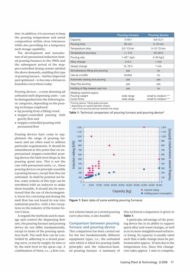
Figure 1: Basic data of some existing pouring furnaces
HC_02_06_P9.indd 17 17.06.16 09:49
K MELTING SHOP
18 Casting Plant & Technology 2/2016
no metal can be poured during this interval unless the process comprises two pouring devices. A pouring device of this type is suitable mainly for use on molding machines with longer cy-cle times and medium or low pouring weights.
As regards the achievable metal dos-ing accuracy, no reliable figures or eval-
uations that would support a compari-son of this kind are available.
The advantages of a pouring furnace, needless to say, reside in the low tem-perature loss and the high tempera-ture constancy achievable by heating, as well as in the accurate control of the melt composition, a longer melt hold-ing ability, and the fact that fresh met-
al can be added without interrupting the pouring process. As a result, mol-ten metal can be poured continuously.
As reported in an earlier article in this periodical [2], the pouring fur-nace scores better in terms of ener-gy consumption when measured in multi-shift operation. The energy in-put needed to compensate for the tem-perature losses was taken into account in this comparison.
Pouring furnaces for cast ironFurnace sizesThe design principle of the pressurized pouring furnace with stopper control system can be assumed to be known, refer to Figure 1. In the following text we shall therefore limit ourselves to a presentation of individual new devel-opments.
The basic data of some pouring furnace projects realized in practice ( Figure 1) illustrate the wide ranges of capacity and power ratings involved. If one considers the holding power consumption, it emerges that pour-ing furnaces are typically built with a higher superheating power than chan-nel-type induction furnaces. A typical rating would be one that enables the
Figure 2: Main menu of the multi-touch display
Figure 3: New stopper actuator
HC_02_06_P9.indd 18 17.06.16 09:49
Casting Plant & Technology 2/2016 19
furnace to superheat the metal by 90 – 110 K in one hour. This is because rap-id superheating may become neces-sary in pouring furnace applications where the incoming metal tempera-ture is too low, e.g., to reach the speci-fied melt pouring temperature in min-imum time again after refilling. The small holding volume will not suffice to provide the required temperature equalization, especially if the vessel is depleted to the level of the liquid heel.
In some cases, however, a much higher superheating power is required. Thus, one 5-t pouring furnace instal-lation was equipped with a 1000 kW powerpack enabling it to realize a 90 K temperature rise within approx. 4 min. In order to ensure a rapid temperature equalization between the metal in the filling gate siphon and in the furnace vessel, the furnace pressure is lowered and then increased again to obtain a “pumping” effect.
It should not be left unmentioned here that in pouring magnesium-treat-ed cast iron (for making spheroidal graphite or “S.G.” iron), a little more superheating power is desirable. The in-ductor rating should be approx. 50 kW higher in this case in order to prevent accretions of magnesium oxide slag [3].
The chart also shows that the specif-ic holding power consumption natu-rally decreases significantly with in-creasing furnace size.
Heating systemIt is generally known that the heat for holding and superheating the molten metal is generated by a channel in-ductor comprizing a U-shaped chan-nel which is attached to the side or on the bottom of the vessel. The trend to-day is for inductors to be fitted at the vessel bottom, especially for pouring S.G. iron.
The use of coreless inductors (of crucible shape), although resulting in a somewhat higher energy consump-tion, had originally promised a num-ber of process advantages. However, it has fallen short of gaining the expect-ed success.
The heat loss of the coil is absorbed by a water cooling system which also cools the inductor. Since the induc-
tor rating may range from 150 kW to 1200 kW (refer to Figure 1), the design and, especially, the channel geometry must be adapted to the specific power level. One approach being considered here is to adopt air-cooling for induc-tors in the lower power range. In this context, developers are focusing on en-larging the heat-dissipating surface of the inductor.
These design changes are currently implemented in a project involving a 4-t pouring furnace with an air-cooled 250 kW inductor. However, no general trend for inductors in the lower power bracket can be derived from this case. Project related decisions remain to be taken individually, on a case-by-case basis, weighing the benefits and draw-backs anew for each system.
It need not be mentioned here that air-cooled inductors for pouring fur-naces are not, by themselves, a novel-ty feature.
The electric power supply of pour-ing furnaces is based mainly on rugged mains-frequency switchgear systems. In individual cases, frequency convert-ers relying on IGBT technology are to-day employed as well where technical
conditions – especially regarding in-finitely variable power control – sug-gest their use. One example is the proj-ect of a 5-t pouring furnace equipped with an IGBT converter system that
Figure 4: Trial setup comprising the new stopper actuator and Belysa ca-mera system
Figure 5: Newly developed inoculation system
HC_02_06_P9.indd 19 17.06.16 09:49
K MELTING SHOP
20 Casting Plant & Technology 2/2016
delivers up to 1000 kW to provide ro-bust superheating by 90 K in minimum time. It should be noted here that the system’s holding power consumption is in the region of 150 kWh/h, and that the typical power supply of a 5-t fur-nace lies in the 200 – 300 kW range.
In the case considered here, the accu-rate power control required for a super-heating process depending on furnace parameters (furnace contents, tem-perature) suggested the use of an IGBT converter system. Further circuit en-gineering options supported by IGBT converter technology, e.g., variable fre-quency operation or the use of a joint power supply for two distinct furnac-es, have not found their way into prac-tical pouring furnace applications to date. From this we may conclude that the use of frequency converters is like-ly to remain limited to individual cases where this technology provides identi-fiable benefits.
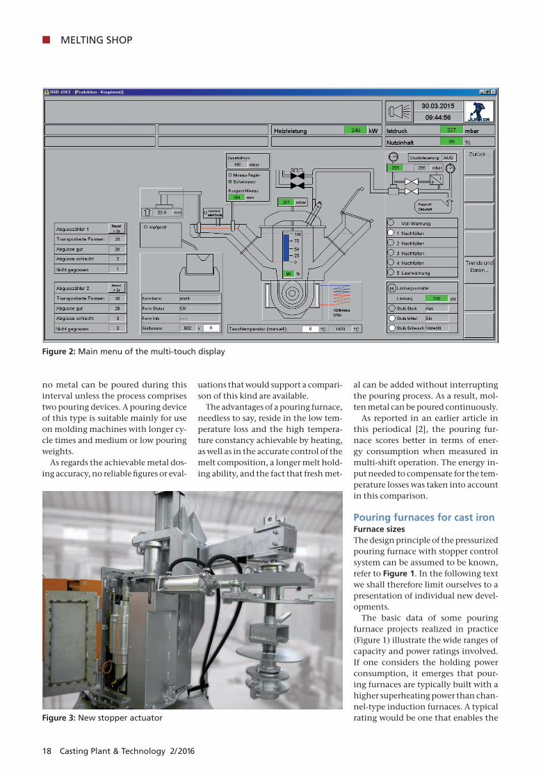
Process management and controlThe standard today is a PC-based pro-cess control and visualization system to monitor, supervise and operate all pouring furnace components and their functions. In addition, these systems handle the storage, management and transmission of technical parameters.
The human/machine interface com-prises a TFT monitor with mouse con-
trol and a sealed keypad for entering alphanumeric characters and control commands.
At present, the changeover to sys-tems with single or multi-touch dis-play units is proceeding. Figure 2 shows the main menu prepared for use with this new generation.
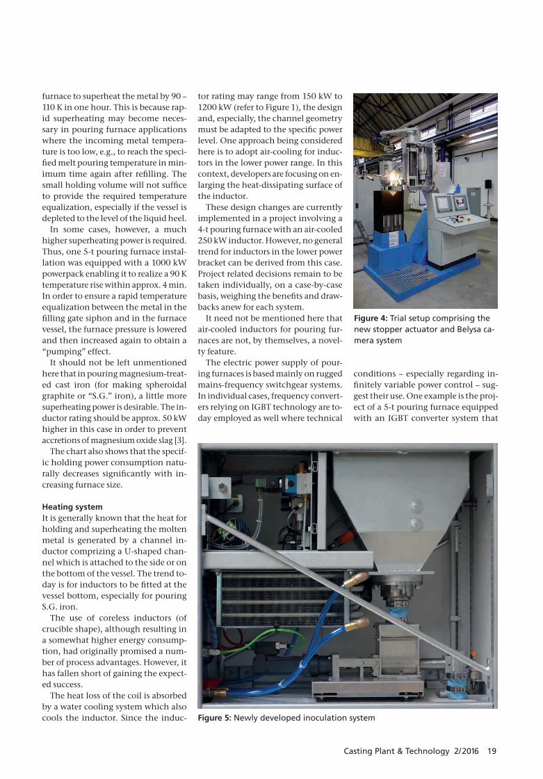
The dispensing accuracy is deter-mined, among other factors, by the technical performance of the stopper control system and its actuator. For precise operation of the stopper actua-tor, fast and accurate positioning of the stopper are essential. Further require-ments include an adjustable, controlled stopper closing force, automatic nozzle wear compensation and appropriate nozzle cleaning and seating devices.
The new electrical stopper actuator developed by Otto Junker, Simmerath, Germany, (Figure 3) meets these de-mands with a high degree of reliability. The new stopper control system moves the stopper via a genuine linear actua-tor using magnetic force. The only mov-ing part is the push rod (secondary part) with its machined spiral-shaped groove. This push rod is separated by a defined air gap from the hollow stator shaft (pri-mary part, two-pole wound laminated core). As a result, the actuator system operates with virtually no wear.
Due to the low self-retention action of the linear actuator the stopper will
drop under its own weight in the case of a power failure, thus closing off the pouring nozzle. An integrated lever system makes it very easy to raise the stopper manually into a mechanical snap-lock position.
When the stopper control system is switched off at the end of production the linear actuator raises the stopper into the same snap-lock position. Af-ter that the power pack of the actuator is switched off automatically. When the stopper control system is switched on the power pack is energized and the linear actuator automatically moves the stopper from its snap-lock position into the pouring spout nozzle.
The stopper is pressed into the pour-ing nozzle at an adjustable controlled force acting in addition to the force of the stopper’s weight. In this way the stopper and/or nozzle wear is automat-ically compensated up to an adjustable wear limit.
Along with the development of this new stopper actuator, a new camera system (by Belysa) measuring the me-tal level in the mold sprue cup as in-put for controlling the pouring rate has undergone trials.
Figure 4 shows the trial set-up con-sisting of the new stopper actuator and the Belysa camera system. The set-up of a pouring furnace spout system in-cluding a complete control panel made
Figure 6: Schematic illustration of the swivelling dual-stopper system
HC_02_06_P9.indd 20 17.06.16 09:49
Casting Plant & Technology 2/2016 21
it possible to test the equipment under near-real-world conditions. Further trials in an industrial environment showed a high dosing accuracy, with only a few millimetres deviation from the specified melt level in the sprue cup. Meanwhile, following long-term eval-uation, the new stopper actuator and camera system have been successfully integrated in a number of projects.
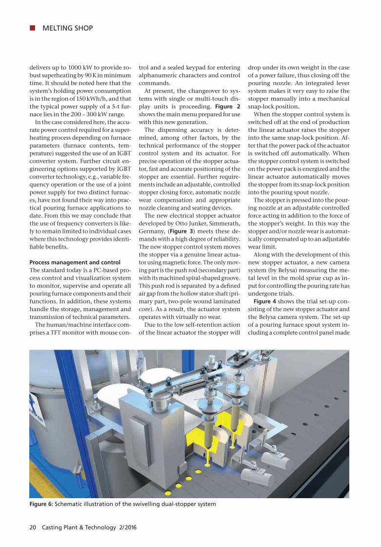
For a metal stream inoculation of optimum effectiveness, it is necessary to introduce a closely defined amount of inoculant into the pouring stream throughout the pouring process. For quality control purposes, the amount of inoculant added should be deter-mined and documented.
Since existing inoculating systems fail to meet these requirements in a perfect manner and the dosing process is not accurate enough, the concept of a new equipment generation was de-veloped and tested.
The new inoculation system ( Figure 5) operates as follows: Inoculant is pre-metered into an intermediate ves-sel from where a frequency controlled fine-metering screw drive delivers it to a precision weighing system for accurate control and logging of the inoculant quantity. The system thus provides con-trol of the inoculation rate while also recording the amount of inoculant ac-tually added to each pour.
A PLC is employed to manage and control the system, with a touch panel or Otto Junker’s proprietary JOKS sys-tem providing visualization and op-erating functions. Stored data can be polled via an appropriate interface.
Extensive testing has demonstrated the system’s full operability and high metering accuracy.
At the time of writing this report, the prototype of the new inoculation sys-tem was undergoing long-time testing under production conditions at Ergo-cast Guss GmbH, Jünkerath, Germany.
Special pouring techniquesDirect pouring with a controlled sin-gle-stopper system into the sprue cup of the mold is not feasible in some cas-es, e.g., where
» an inoculation or alloying step with weight-based dosing is to be carried out directly before the pouring op-eration,
» an open top runner is used on the mold,
» the stopper cannot be positioned di-rectly over the sprue for space reasons,
» the pouring time exceeds the cycle time of the molding machine,
» it is necessary to fill two molds, or one mold with two sprue cups, si-multaneously or
» the molding machine advances the molds continuously.
In such applications the use of dual- stopper, tundish or launder based solu-tions suggests itself to meet the techni-cal requirements [4].
In order to produce two distinct cast-ings in one molding box with separate sprue cups, a dual-stopper system must be used (even triple systems have been realized by now). The same applies if melt must be poured into two sprue cups for a single casting.
The sprues can be filled with molten metal either concurrently or one after the other. A dual-stopper system is also used for filling two mold boxes at the same time.
On molding machines with a very high output and hence, a short time to complete a mold, the available cycle time may be shorter than the required pouring time. Through the use of tra-velling tundishes, the requisite pour-ing times can nevertheless be attained.
An alternative solution is to double the available pouring time by advanc-ing two molds or mold boxes simulta-neously so that the cycle will comprise two concurrent molding operations. For the pouring furnace, this means that two molds must be filled at the same time, with a possible change in the sprue cup position.
This requirement is addressed by a newly developed Otto Junker solution [5] involving two independently swiv-
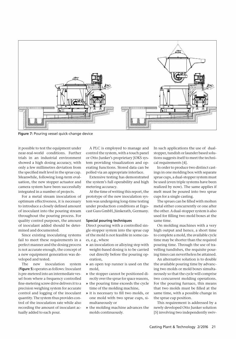
Figure 7: Pouring vessel quick-change device
HC_02_06_P9.indd 21 17.06.16 09:49
K MELTING SHOP
22 Casting Plant & Technology 2/2016
elling stoppers. Figure 6 outlines the system concept. The extent to which this system can actually be adopted in practice remains to be confirmed by in-dustrial trials.
Quick change of the pouring vesselNecessary relinings of the inductor or pouring vessel and other repair or maintenance procedures may, more or less frequently, call for a pouring vessel replacement. This is a time-con-suming process which may result in down times of the molding machine. Where such replacements are fre-quent, e.g., due to short inductor life-time, the associated losses may be hard to accept.
In the case of a project at Gienanth GmbH, Eisenberg, Germany, the aim was to implement a pouring vessel change within one shift, or in less than 6 h. In two-shift operation, loss of pro-duction will thus be avoided even if the change requirement should arise during the week. Needless to say, this scenario assumes that a second fur-nace vessel is available fully sintered and ready for installation.
Providing a vessel quick-change ca-pability on a pressurized pouring fur-nace imposed a number of modifi-cations to the existing design. Chief among these is an additional platform fitted on the furnace vessel by which the entire vessel can be lifted out with-out the tilting frame (Figure 7). For this operation, all ancillary equip-ment such as the compressed air sup-ply, stopper actuator, etc., remain in place in the furnace frame or are mere-ly swung out of the way, while the elec-tric power and water supply lines are disconnected via quick-couplings.
The quick-change system is also used on Otto Junker’s unheated UGD type pouring devices, as further projects demonstrate.
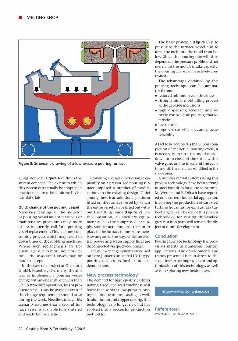
New process technology The demand for high-quality castings having a reduced wall thickness will boost the use of the low-pressure cast-ing technique in iron casting as well. In aluminium and copper casting, this technology is no longer new but has evolved into a successful production method [6].
The basic principle (Figure 8) is to pressurize the furnace vessel and to force the melt into the mold from be-low. Since the pouring rate will thus depend on the pressure profile and not merely on the mold’s intake capacity, the pouring curve can be actively con-trolled.
The advantages obtained by this pouring technique can be summa-rized thus:
» reduced minimum wall thickness » rising laminar mold filling process without oxide inclusions
» high dispensing accuracy and ac-tively controllable pouring charac-teristics
» less returns » improved cost efficiency and process reliability
A fact to be accepted is that, upon com-pletion of the actual pouring cycle, it is necessary to turn the mold upside down or to close off the sprue with a valve gate, or else to extend the cycle time until the melt has solidified in the sprue area.
A number of trial systems using this process technology have been serving in steel foundries for quite some time. M. Werner and E. Dötsch have report-ed on a current industrial application involving the production of cast steel turbine housings for exhaust gas tur-bochargers [7]. The use of this process technology for casting thin-walled grey cast iron parts will remain the ob-ject of future development.
ConclusionPouring furnace technology has prov-en its merits in numerous foundry applications. The developments and trends presented herein attest to the scope for further improvement and op-timization of this technology, as well as for exploring new fields of use.
http://www.otto-junker.de/en
References:www.cpt-international.com
Figure 8: Schematic drawing of a low-pressure pouring furnace
HC_02_06_P9.indd 22 17.06.16 09:49