Embed Size (px)
Citation preview

POTSwap – HSPA910PS v1.00Product User Manual
Bulletin JA16-GSM-UMRevision P09Date 03 Jan 2018
POTSwap v1.00 User Manual JA16-UM Page 2 Rev: P09 Date: 01/03/18© Copyright 2018 Janus Remote Communications Specifications subject to change without notice
All Rights Reserved See website for latest revision. Not intended for life support applications.
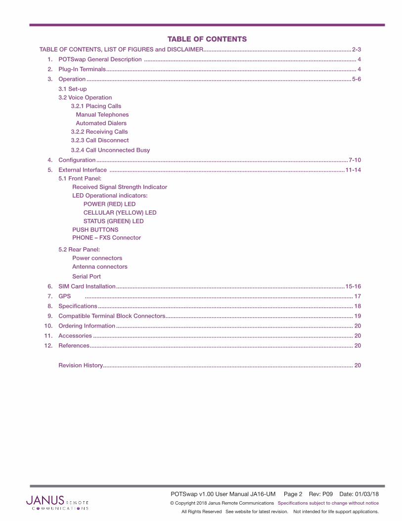
TABLE OF CONTENTSTABLE OF CONTENTS, LIST OF FIGURES and DISCLAIMER ..........................................................................................2-3
1. POTSwap General Description ................................................................................................................................. 4
2. Plug-In Terminals ........................................................................................................................................................ 4
3. Operation .................................................................................................................................................................5-6
3.1 Set-up 3.2 Voice Operation 3.2.1 Placing Calls Manual Telephones Automated Dialers 3.2.2 Receiving Calls 3.2.3 Call Disconnect
3.2.4 Call Unconnected Busy
4. Configuration .........................................................................................................................................................7-10
5. External Interface ...............................................................................................................................................11-14 5.1 Front Panel: Received Signal Strength Indicator LED Operational indicators: POWER (RED) LED CELLULAR (YELLOW) LED STATUS (GREEN) LED PUSH BUTTONS PHONE – FXS Connector
5.2 Rear Panel: Power connectors Antenna connectors
Serial Port
6. SIM Card Installation ...........................................................................................................................................15-16
7. GPS ................................................................................................................................................................... 17
8. Specifications ........................................................................................................................................................... 18
9. Compatible Terminal Block Connectors .................................................................................................................. 19
10. Ordering Information ................................................................................................................................................ 20
11. Accessories .............................................................................................................................................................. 20
12. References ................................................................................................................................................................ 20
Revision History ........................................................................................................................................................ 20
POTSwap v1.00 User Manual JA16-UM Page 3 Rev: P09 Date: 01/03/18© Copyright 2018 Janus Remote Communications Specifications subject to change without notice
All Rights Reserved See website for latest revision. Not intended for life support applications.
TABLE OF CONTENTS continued
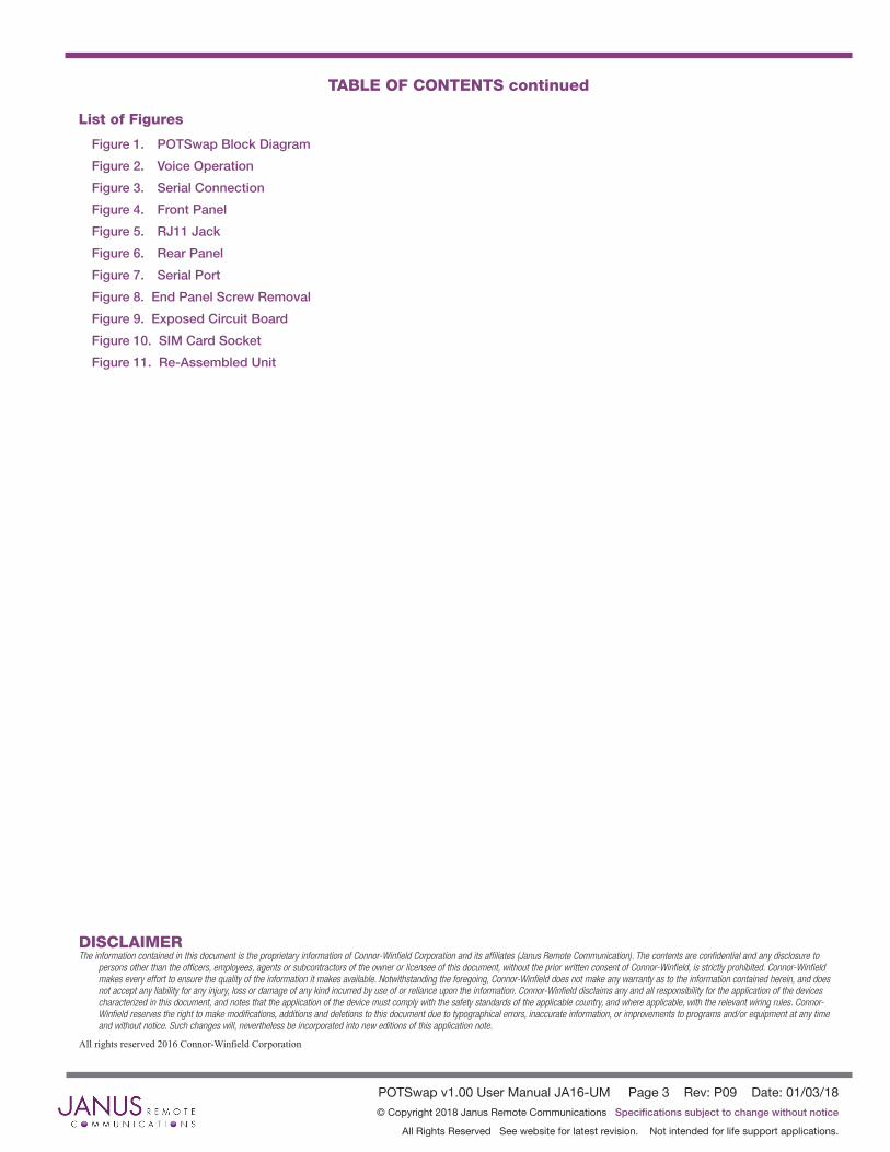
DISCLAIMERThe information contained in this document is the proprietary information of Connor-Winfield Corporation and its affiliates (Janus Remote Communication). The contents are confidential and any disclosure to
persons other than the officers, employees, agents or subcontractors of the owner or licensee of this document, without the prior written consent of Connor-Winfield, is strictly prohibited. Connor-Winfield makes every effort to ensure the quality of the information it makes available. Notwithstanding the foregoing, Connor-Winfield does not make any warranty as to the information contained herein, and does not accept any liability for any injury, loss or damage of any kind incurred by use of or reliance upon the information. Connor-Winfield disclaims any and all responsibility for the application of the devices characterized in this document, and notes that the application of the device must comply with the safety standards of the applicable country, and where applicable, with the relevant wiring rules. Connor-Winfield reserves the right to make modifications, additions and deletions to this document due to typographical errors, inaccurate information, or improvements to programs and/or equipment at any time and without notice. Such changes will, nevertheless be incorporated into new editions of this application note.
All rights reserved 2016 Connor-Winfield Corporation
List of Figures
Figure 1. POTSwap Block Diagram
Figure 2. Voice Operation
Figure 3. Serial Connection
Figure 4. Front Panel
Figure 5. RJ11 Jack
Figure 6. Rear Panel
Figure 7. Serial Port
Figure 8. End Panel Screw Removal
Figure 9. Exposed Circuit Board
Figure 10. SIM Card Socket
Figure 11. Re-Assembled Unit
POTSwap v1.00 User Manual JA16-UM Page 4 Rev: P09 Date: 01/03/18© Copyright 2018 Janus Remote Communications Specifications subject to change without notice
All Rights Reserved See website for latest revision. Not intended for life support applications.
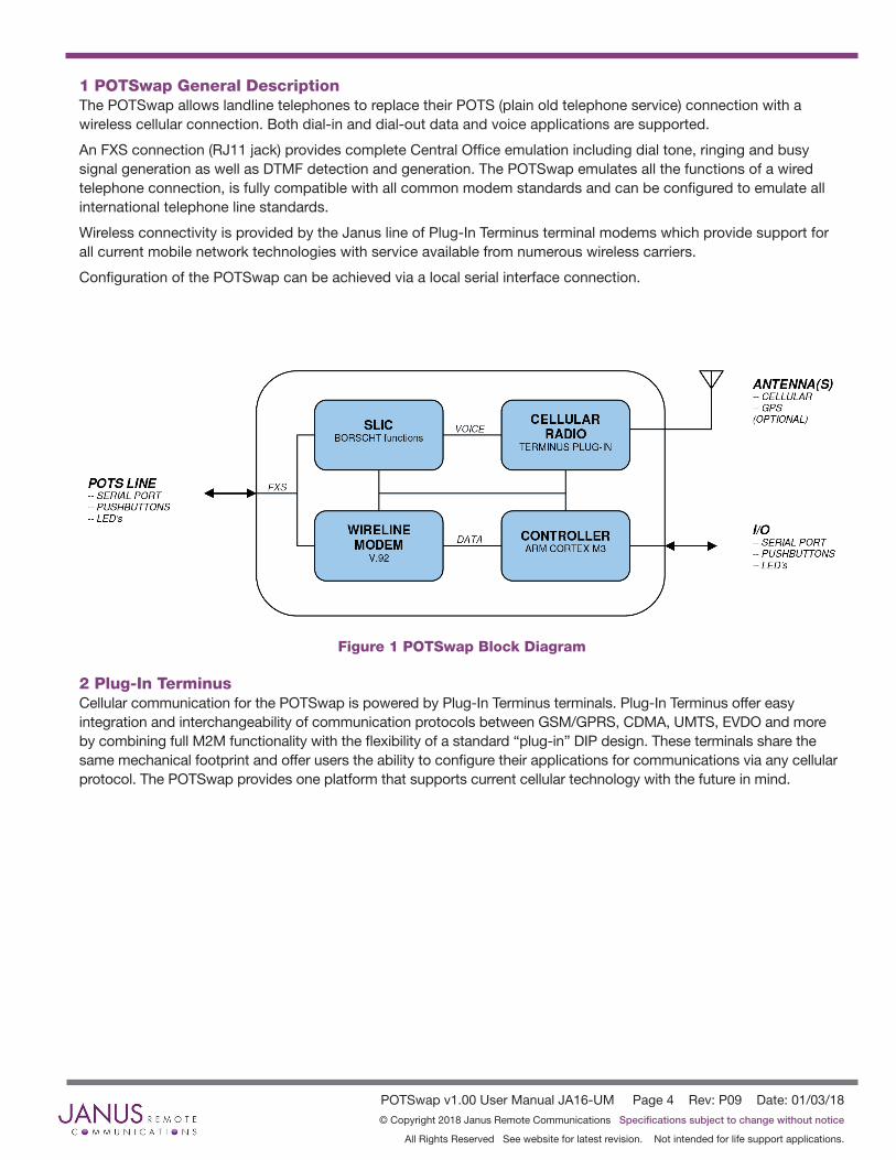
1 POTSwap General DescriptionThe POTSwap allows landline telephones to replace their POTS (plain old telephone service) connection with a wireless cellular connection. Both dial-in and dial-out data and voice applications are supported.
An FXS connection (RJ11 jack) provides complete Central Office emulation including dial tone, ringing and busy signal generation as well as DTMF detection and generation. The POTSwap emulates all the functions of a wired telephone connection, is fully compatible with all common modem standards and can be configured to emulate all international telephone line standards.
Wireless connectivity is provided by the Janus line of Plug-In Terminus terminal modems which provide support for all current mobile network technologies with service available from numerous wireless carriers.
Configuration of the POTSwap can be achieved via a local serial interface connection.
2 Plug-In TerminusCellular communication for the POTSwap is powered by Plug-In Terminus terminals. Plug-In Terminus offer easy integration and interchangeability of communication protocols between GSM/GPRS, CDMA, UMTS, EVDO and more by combining full M2M functionality with the flexibility of a standard “plug-in” DIP design. These terminals share the same mechanical footprint and offer users the ability to configure their applications for communications via any cellular protocol. The POTSwap provides one platform that supports current cellular technology with the future in mind.
Figure 1 POTSwap Block Diagram
POTSwap v1.00 User Manual JA16-UM Page 5 Rev: P09 Date: 01/03/18© Copyright 2018 Janus Remote Communications Specifications subject to change without notice
All Rights Reserved See website for latest revision. Not intended for life support applications.
3 Operation3.1 Set-Up:
Operating the POTSwap with voice (telephone) equipment can be achieved through the following steps:
1. Gather the required equipment:
• POTSwap
• Power Supply - This can be hard-wired from a user supplied power source via the terminal block header (See section 9 - Compatible Terminal Block Connectors) or using the optional wall transformer (See section 11 - Accessories).
• Cellular antenna - A 5-band (‘penta-band’) GSM cellular antenna is recommended. An optional cellular antenna is available (See section 11 - Accessories).
• GPS antenna - On units equiped with a GPS antenna connector, a GPS antenna may be connected. (See section 11 - Accessories)
• The HSPA910PS model of the POTSwap requires an activated SIM card. Installation requires a Torx T10 screwdriver (See section 6 - SIM Card Installation).
2. Install the SIM card. The HSPA version POTSwap requires a mini (2FF size) SIM card. See section 6 - SIM Card Installation..
3. Connect a cellular antenna to the SMA connector labeled ‘CELLULAR’. This can be a local antenna or a remote antenna connected by a coaxial cable.
4. [Optional] Connect a GPS antenna to the SMA connector labeled ‘GPS’. (See Section 7 - GPS.)
5. Connect power to the unit.
Once powered, the unit should show a connection to the cellular carrier within a minute. This will be indicated by a rapidly flashing GREEN ‘STATUS’ LED, a blinking ‘CELLULAR’ LED, and a steady signal strength indication on the Received Signal Strength LED stack.
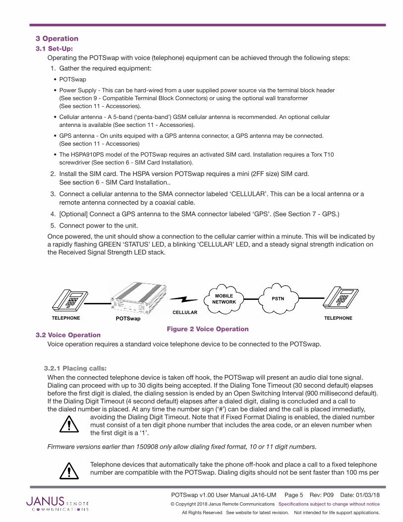
3.2 Voice OperationVoice operation requires a standard voice telephone device to be connected to the POTSwap.
3.2.1 Placing calls:When the connected telephone device is taken off hook, the POTSwap will present an audio dial tone signal. Dialing can proceed with up to 30 digits being accepted. If the Dialing Tone Timeout (30 second default) elapses before the first digit is dialed, the dialing session is ended by an Open Switching Interval (900 millisecond default). If the Dialing Digit Timeout (4 second default) elapses after a dialed digit, dialing is concluded and a call to the dialed number is placed. At any time the number sign (‘#’) can be dialed and the call is placed immediatly,
avoiding the Dialing Digit Timeout. Note that if Fixed Format Dialing is enabled, the dialed number must consist of a ten digit phone number that includes the area code, or an eleven number when the first digit is a ‘1’.
Firmware versions earlier than 150908 only allow dialing fixed format, 10 or 11 digit numbers.
Telephone devices that automatically take the phone off-hook and place a call to a fixed telephone number are compatible with the POTSwap. Dialing digits should not be sent faster than 100 ms per
TELEPHONE
MOBILE NETWORK
PSTN
CELLULAR
VOICE
TELEPHONE POTSwap
Figure 2 Voice Operation
POTSwap v1.00 User Manual JA16-UM Page 6 Rev: P09 Date: 01/03/18© Copyright 2018 Janus Remote Communications Specifications subject to change without notice
All Rights Reserved See website for latest revision. Not intended for life support applications.
digit, with a minimum DTMF tone duration of 45 ms.
The POTSwap is compatible with DTMF dialing only. Pulse dialing will not work.
3 Operation continued3.2 Voice Operation continued
3.2.2 Receiving calls:Incoming calls will cause the POTSwap to generate a ringing signal on the phone line. Taking the connected telephone line off-hook will answer the incoming call. Note that cellular carriers typically impose a 30 second limit on unanswered ringing before a call is transferred to a voice mail system.
3.2.3 Call Disconnect:A call can always be terminated by placing the connected telephone equipment on-hook. If a cellular call is terminated on the carrier side (the result of a connected party ending the call or due to loss of signal) the POTSwap will use an Open Switching Interval to aid in disconnecting automated type telephone equipment. It removes the voltage from the phone line connection for a short time to signal that the call has been terminated. The OSI interval can be adjusted using the user configuration menu.
3.2.4 Unconnected Busy:In some instances when dialing a number that is busy, the cellular carriers will not make an audio connection to a busy tone. If this occurs, the POTSwap will generate the busy tone locally for a period defined by the user configurable Busy Dwell Timeout parameter. Following the busy tone, the POTSwap will terminate the call by generating an Open Switching Interval (see section 4 - Configuration).
POTSwap v1.00 User Manual JA16-UM Page 7 Rev: P09 Date: 01/03/18© Copyright 2018 Janus Remote Communications Specifications subject to change without notice
All Rights Reserved See website for latest revision. Not intended for life support applications.
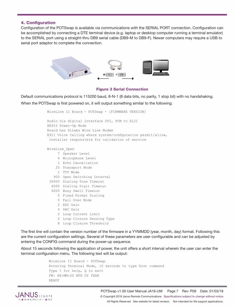
4. ConfigurationConfiguration of the POTSwap is available via communications with the SERIAL PORT connection. Configuration can be accomplished by connecting a DTE terminal device (e.g. laptop or desktop computer running a terminal emulator) to the SERIAL port using a straight-thru DB9 serial cable (DB9-M to DB9-F). Newer computers may require a USB to serial port adaptor to complete the connection.
Figure 3 Serial Connection
Default communications protocol is 115200 baud, 8-N-1 (8 data bits, no parity, 1 stop bit) with no handshaking.
When the POTSwap is first powered on, it will output something similar to the following:
WireLine II Board - POTSwap - [FIRMWARE VERSION]
Audio via digital interface DVI, PCM to SLICHE910 Power-Up ModeBoard has SiLabs Wire Line ModemE911 Voice Calling where system/configuration permit/allow, Installer responsible for validation of service
WireLine_Open 7 Speaker Level 4 Microphone Level 1 Echo Cancellation 25 Transport Mode 1 TTY Mode 900 Open Switching Interval 30000 Dialing Tone Timeout 4000 Dialing Digit Timeout 6000 Busy Dwell Timeout 0 Fixed Format Dialing 0 Fail Over Mode 2 ADC Gain 4 DAC Gain 2 Loop Current Limit 0 Loop Closure Sensing Type 8 Loop Closure Threshold
The first line will contain the version number of the firmware in a YYMMDD (year, month, day) format. Following this are the current configuration settings. Several of these parameters are user configurable and can be adjusted by entering the CONFIG command during the power-up sequence.
About 15 seconds following the application of power, the unit offers a short interval wherein the user can enter the terminal configuration menu. The following text will be output:
WireLine II Board - POTSwapEntering Terminal Mode, 10 seconds to type first commandType ? for help, Q to exitFW: HH:MM:SS MTH DY YEARREADY

POTSwap v1.00 User Manual JA16-UM Page 8 Rev: P09 Date: 01/03/18© Copyright 2018 Janus Remote Communications Specifications subject to change without notice
All Rights Reserved See website for latest revision. Not intended for life support applications.
4. Configuration continued
At this point the user has 10 seconds to enter one of the following commands followed by a line termination (‘Enter’ key on PC’s):
TERMINAL MENU COMMANDS
COMMAND FUNCTION?, H Outputs the current menu options.Q, QUIT Exits the menu and causes the POTSwap to proceed with the normal operation.DEBUG xx Factory use onlyDUMP Adr Len Factory use onlyXMODEM Download upgrade binaryREBOOT Restart ApplicationCONFIG Configure SettingsIDENTIFY Display Cellular IMEI (International Mobile station Equipment Identity) and phone number
These commands are NOT case sensitive. Terminal menu commands operate as follows:
?, H: Entering a ‘?’ or ‘H’ character will output the Terminal menu command menu again. It can be useful if the menu has scrolled off of a screen.
Q ,QUIT: Entering ‘Q’ or ‘QUIT’ will exit the DEBUG menu and continue with the normal start-up and operation of the POTSwap.
DEBUG xx: DO NOT USE - Factory use only.
DUMP Adr Len: DO NOT USE - Factory use only.
XMODEM: Used for firmware upgrades.
REBOOT: Entering ‘REBOOT’ will restart the POTSwap, similar to pressing the RESET button.
CONFIG: Entering ’CONFIG’ will cause the configuration menu to be output:
Janus Remote Communications - WireLine II Board - POTSwap Configuration
=======================================================================Microphone Level [4] 0-7Speaker Level [7 ] 0-14Echo Cancellation [1] 0-1Open Switching Interval [900 ] 0-1200 msDialing Tone Timeout [30000] 500-60000 msDialing Digit Timeout [4000 ] 250-15000 msBusy Dwell Timeout [6000 ] 1000-30000 msFixed Format Dialing [0] 0-1Fail Over Mode [0] 0-2
GSM Transport Mode [25] 12,22,25GSM TTY Mode [1] 0-1
SLIC ADC Gain [2] 0-8SLIC DAC Gain [4] 0-8
Loop Current Limit [2] 0-7Loop Closure Sense Type [0] 0-1Loop Closure Threshold [8 ] 0-63
Press M=Modify, D=Defaults, X=Exit and Save, Q=Quit and Discard
The configuration menu lists the name of the parameter, the current setting (in brackets), and the range or values of settings available. These settings may vary depending on the model of Plug-In Terminus terminal used in the POTSwap. Following the list of parameters are options for changing the configuration settings or leaving this menu: M, D, X, and Q. These single character command options can be entered in upper or lower case, and no enter key is required.
POTSwap v1.00 User Manual JA16-UM Page 9 Rev: P09 Date: 01/03/18© Copyright 2018 Janus Remote Communications Specifications subject to change without notice
All Rights Reserved See website for latest revision. Not intended for life support applications.
4. Configuration continued
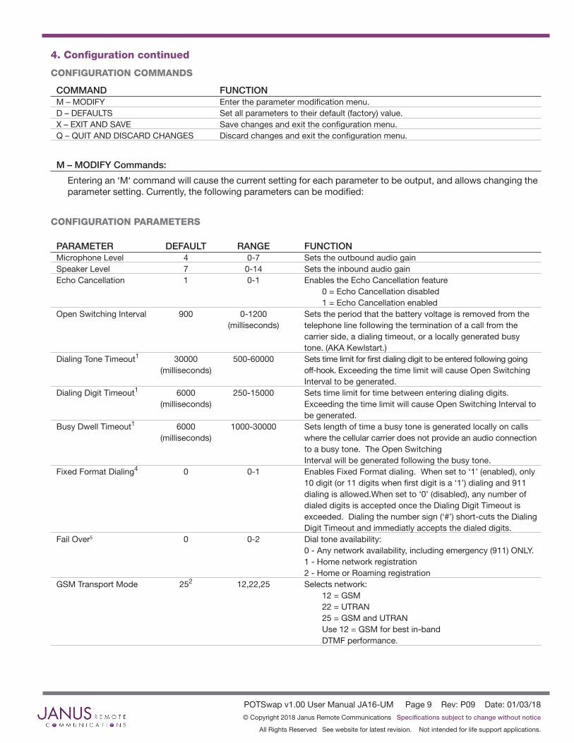
CONFIGURATION COMMANDS
COMMAND FUNCTIONM – MODIFY Enter the parameter modification menu.D – DEFAULTS Set all parameters to their default (factory) value.X – EXIT AND SAVE Save changes and exit the configuration menu.Q – QUIT AND DISCARD CHANGES Discard changes and exit the configuration menu.
M – MODIFY Commands:
Entering an ‘M‘ command will cause the current setting for each parameter to be output, and allows changing the parameter setting. Currently, the following parameters can be modified:
CONFIGURATION PARAMETERS
PARAMETER DEFAULT RANGE FUNCTIONMicrophone Level 4 0-7 Sets the outbound audio gainSpeaker Level 7 0-14 Sets the inbound audio gainEcho Cancellation 1 0-1 Enables the Echo Cancellation feature 0 = Echo Cancellation disabled 1 = Echo Cancellation enabledOpen Switching Interval 900 0-1200 Sets the period that the battery voltage is removed from the (milliseconds) telephone line following the termination of a call from the carrier side, a dialing timeout, or a locally generated busy tone. (AKA Kewlstart.) Dialing Tone Timeout1 30000 500-60000 Sets time limit for first dialing digit to be entered following going (milliseconds) off-hook. Exceeding the time limit will cause Open Switching Interval to be generated.Dialing Digit Timeout1 6000 250-15000 Sets time limit for time between entering dialing digits. (milliseconds) Exceeding the time limit will cause Open Switching Interval to be generated.Busy Dwell Timeout1 6000 1000-30000 Sets length of time a busy tone is generated locally on calls (milliseconds) where the cellular carrier does not provide an audio connection to a busy tone. The Open Switching Interval will be generated following the busy tone.Fixed Format Dialing4 0 0-1 Enables Fixed Format dialing. When set to ‘1’ (enabled), only 10 digit (or 11 digits when first digit is a ‘1’) dialing and 911 dialing is allowed.When set to ‘0’ (disabled), any number of dialed digits is accepted once the Dialing Digit Timeout is exceeded. Dialing the number sign (‘#’) short-cuts the Dialing Digit Timeout and immediatly accepts the dialed digits.Fail Over5 0 0-2 Dial tone availability: 0 - Any network availability, including emergency (911) ONLY. 1 - Home network registration 2 - Home or Roaming registrationGSM Transport Mode 252 12,22,25 Selects network: 12 = GSM 22 = UTRAN 25 = GSM and UTRAN Use 12 = GSM for best in-band DTMF performance.
POTSwap v1.00 User Manual JA16-UM Page 10 Rev: P09 Date: 01/03/18© Copyright 2018 Janus Remote Communications Specifications subject to change without notice
All Rights Reserved See website for latest revision. Not intended for life support applications.
4. Configuration continued
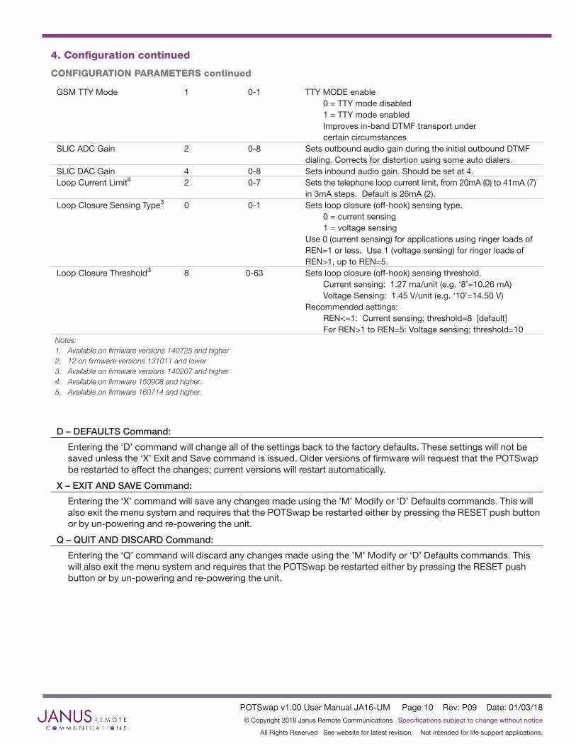
CONFIGURATION PARAMETERS continued
GSM TTY Mode 1 0-1 TTY MODE enable 0 = TTY mode disabled 1 = TTY mode enabled Improves in-band DTMF transport under certain circumstances SLIC ADC Gain 2 0-8 Sets outbound audio gain during the initial outbound DTMF dialing. Corrects for distortion using some auto dialers.SLIC DAC Gain 4 0-8 Sets inbound audio gain. Should be set at 4.Loop Current Limit4 2 0-7 Sets the telephone loop current limit, from 20mA (0) to 41mA (7) in 3mA steps. Default is 26mA (2).Loop Closure Sensing Type3 0 0-1 Sets loop closure (off-hook) sensing type. 0 = current sensing 1 = voltage sensing Use 0 (current sensing) for applications using ringer loads of REN=1 or less. Use 1 (voltage sensing) for ringer loads of REN>1, up to REN=5.Loop Closure Threshold3 8 0-63 Sets loop closure (off-hook) sensing threshold. Current sensing: 1.27 ma/unit (e.g. ‘8’=10.26 mA) Voltage Sensing: 1.45 V/unit (e.g. ‘10’=14.50 V) Recommended settings: REN<=1: Current sensing; threshold=8 [default] For REN>1 to REN=5: Voltage sensing; threshold=10Notes:1. Availableonfirmwareversions140725andhigher2. 12onfirmwareversions131011andlower3. Availableonfirmwareversions140207andhigher4. Availableonfirmware150908andhigher.5. Availableonfirmware160714andhigher.
D – DEFAULTS Command:
Entering the ‘D’ command will change all of the settings back to the factory defaults. These settings will not be saved unless the ‘X’ Exit and Save command is issued. Older versions of firmware will request that the POTSwap be restarted to effect the changes; current versions will restart automatically.
X – EXIT AND SAVE Command:
Entering the ‘X’ command will save any changes made using the ’M’ Modify or ‘D’ Defaults commands. This will also exit the menu system and requires that the POTSwap be restarted either by pressing the RESET push button or by un-powering and re-powering the unit.
Q – QUIT AND DISCARD Command:
Entering the ‘Q’ command will discard any changes made using the ’M’ Modify or ‘D’ Defaults commands. This will also exit the menu system and requires that the POTSwap be restarted either by pressing the RESET push button or by un-powering and re-powering the unit.
POTSwap v1.00 User Manual JA16-UM Page 11 Rev: P09 Date: 01/03/18© Copyright 2018 Janus Remote Communications Specifications subject to change without notice
All Rights Reserved See website for latest revision. Not intended for life support applications.
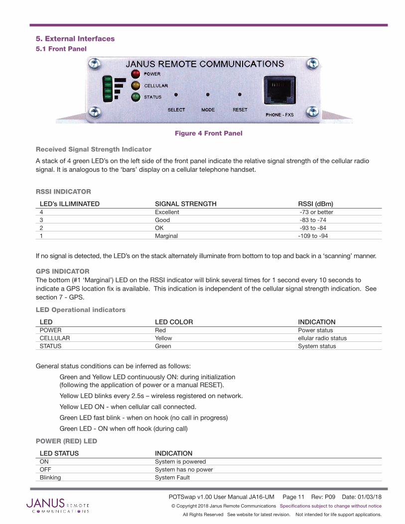
5. External Interfaces5.1 Front Panel
Received Signal Strength Indicator
A stack of 4 green LED’s on the left side of the front panel indicate the relative signal strength of the cellular radio signal. It is analogous to the ‘bars’ display on a cellular telephone handset.
RSSI INDICATOR
LED’s ILLIMINATED SIGNAL STRENGTH RSSI (dBm)4 Excellent -73 or better3 Good -83 to -742 OK -93 to -841 Marginal -109 to -94
If no signal is detected, the LED’s on the stack alternately illuminate from bottom to top and back in a ‘scanning’ manner.
GPS INDICATORThe bottom (#1 ‘Marginal’) LED on the RSSI indicator will blink several times for 1 second every 10 seconds to indicate a GPS location fix is available. This indication is independent of the cellular signal strength indication. See section 7 - GPS.
LED Operational indicators
LED LED COLOR INDICATIONPOWER Red Power statusCELLULAR Yellow ellular radio statusSTATUS Green System status
General status conditions can be inferred as follows:
Green and Yellow LED continuously ON: during initialization (following the application of power or a manual RESET).
Yellow LED blinks every 2.5s – wireless registered on network.
Yellow LED ON - when cellular call connected.
Green LED fast blink - when on hook (no call in progress)
Green LED - ON when off hook (during call)
POWER (RED) LED
LED STATUS INDICATIONON System is poweredOFF System has no powerBlinking System Fault
Figure 4 Front Panel
POTSwap v1.00 User Manual JA16-UM Page 12 Rev: P09 Date: 01/03/18© Copyright 2018 Janus Remote Communications Specifications subject to change without notice
All Rights Reserved See website for latest revision. Not intended for life support applications.
5. External Interfaces continued
CELLULAR (YELLOW) LED:
LED STATUS CELLULAR RADIOOFF OffON Not registered - or - Call activeBlinking 1sec on + 2 sec off Registered in idle * WhentheCELLULARLEDstayson(notregistered)formorethanafewminutesafterpoweringthePOTSwap,itisusuallyanindicationofapoor
antennaconnectionoraproblemwiththeactivationonthecellularnetwork.CheckthattheSIMcardisproperlyinstalledandthatithasvalidactivationwithacellularcarrier.
STATUS (GREEN) LED
LED STATUS INDICATIONON Phone line 9RJ11) is OFF-HOOK (also during initialization)Blinking fast (12.5 Hz) Phone line (RJ11) is ON-HOOKBlinking slow (1 Hz) Initializing
PUSH BUTTONSThree push buttons are provided on the front panel of the POTSwap. These can be operated with a small diameter object such as a paperclip. There is tactile feedback that indicates when the push button has been operated.
Applying pressure to the push buttons beyond the point at which they actuate can damage the switch.
Currently the SELECT and MODE push buttons are not supported. The RESET push button performs the same function as powering the unit off and then on; the configuration parameters are not affected.
PUSH BUTTON FUNCTIONS
PUSH BUTTON FUNCTIONSELECT Future UseMODE Future UseRESET System Restart
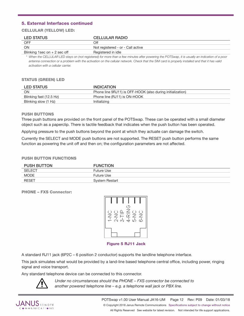
PHONE – FXS Connector:
Figure 5 RJ11 Jack
A standard RJ11 jack (6P2C – 6 position 2 conductor) supports the landline telephone interface.
This jack simulates what would be provided by a land-line based telephone central office, including power, ringing signal and voice transport.
Any standard telephone device can be connected to this connector.
Under no circumstances should the PHONE – FXS connector be connected to another powered telephone line – e.g. a telephone wall jack or PBX line.
POTSwap v1.00 User Manual JA16-UM Page 13 Rev: P09 Date: 01/03/18© Copyright 2018 Janus Remote Communications Specifications subject to change without notice
All Rights Reserved See website for latest revision. Not intended for life support applications.
5. External Interfaces continued5.2 Rear Panel
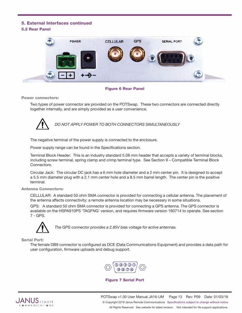
Figure 6 Rear Panel
Figure 7 Serial Port
Power connectors:
Two types of power connector are provided on the POTSwap. These two connectors are connected directly together internally, and are simply provided as a user convenience.
DO NOT APPLY POWER TO BOTH CONNECTORS SIMULTANEOUSLY
The negative terminal of the power supply is connected to the enclosure.
Power supply range can be found in the Specifications section.
Terminal Block Header: This is an industry standard 5.08 mm header that accepts a variety of terminal blocks, including screw terminal, spring clamp and crimp terminal type. See Section 9 – Compatible Terminal Block Connectors.
Circular Jack: The circular DC jack has a 6 mm hole diameter and a 2 mm center pin. It is designed to accept a 5.5 mm diameter plug with a 2.1 mm center hole and a 8.5 mm barrel length. The center pin is the positive terminal.
Antenna Connectors:
CELLULAR: A standard 50 ohm SMA connector is provided for connecting a cellular antenna. The placement of the antenna affects connectivity; a remote antenna location may be necessary in some situations.
GPS: A standard 50 ohm SMA connector is provided for connecting a GPS antenna. The GPS connector is available on the HSPA910PS ‘TAGFNG’ version, and requires firmware version 160714 to operate. See section 7 - GPS.
The GPS connector provides a 2.85V bias voltage for active antennas.
Serial Port:The female DB9 connector is configured as DCE (Data Communications Equipment) and provides a data path for user configuration, firmware uploads and debug support.
5 4 3 2 16789
POTSwap v1.00 User Manual JA16-UM Page 14 Rev: P09 Date: 01/03/18© Copyright 2018 Janus Remote Communications Specifications subject to change without notice
All Rights Reserved See website for latest revision. Not intended for life support applications.
5. External Interfaces continued5.2 Rear Panel continued
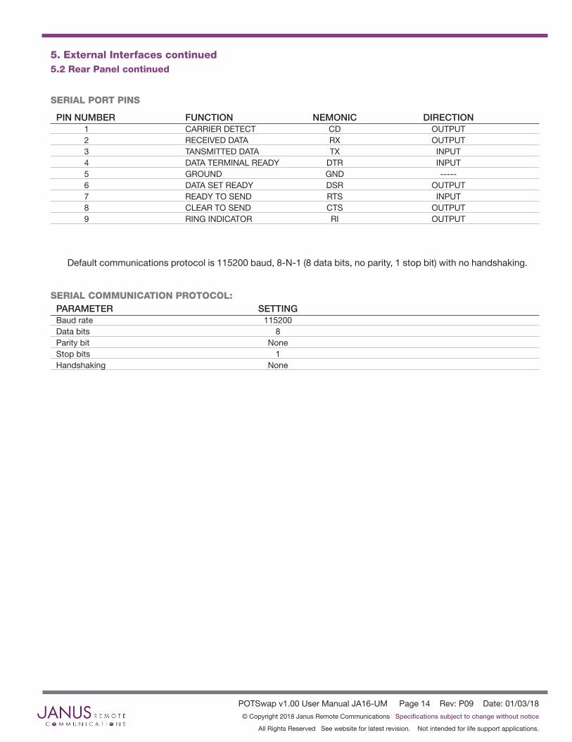
SERIAL PORT PINS
PIN NUMBER FUNCTION NEMONIC DIRECTION 1 CARRIER DETECT CD OUTPUT 2 RECEIVED DATA RX OUTPUT 3 TANSMITTED DATA TX INPUT 4 DATA TERMINAL READY DTR INPUT 5 GROUND GND ----- 6 DATA SET READY DSR OUTPUT 7 READY TO SEND RTS INPUT 8 CLEAR TO SEND CTS OUTPUT 9 RING INDICATOR RI OUTPUT
Default communications protocol is 115200 baud, 8-N-1 (8 data bits, no parity, 1 stop bit) with no handshaking.
SERIAL COMMUNICATION PROTOCOL:PARAMETER SETTINGBaud rate 115200Data bits 8Parity bit NoneStop bits 1Handshaking None
POTSwap v1.00 User Manual JA16-UM Page 15 Rev: P09 Date: 01/03/18© Copyright 2018 Janus Remote Communications Specifications subject to change without notice
All Rights Reserved See website for latest revision. Not intended for life support applications.
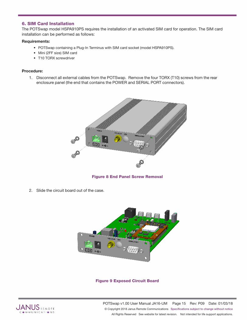
6. SIM Card InstallationThe POTSwap model HSPA910PS requires the installation of an activated SIM card for operation. The SIM card installation can be performed as follows:
Requirements:
• POTSwap containing a Plug-In Terminus with SIM card socket (model HSPA910PS).• Mini (2FF size) SIM card• T10 TORX screwdriver
Procedure:
1. Disconnect all external cables from the POTSwap. Remove the four TORX (T10) screws from the rear enclosure panel (the end that contains the POWER and SERIAL PORT connectors).
2. Slide the circuit board out of the case.
Figure 8 End Panel Screw Removal
Figure 9 Exposed Circuit Board
POTSwap v1.00 User Manual JA16-UM Page 16 Rev: P09 Date: 01/03/18© Copyright 2018 Janus Remote Communications Specifications subject to change without notice
All Rights Reserved See website for latest revision. Not intended for life support applications.
6. SIM Card Installation continued
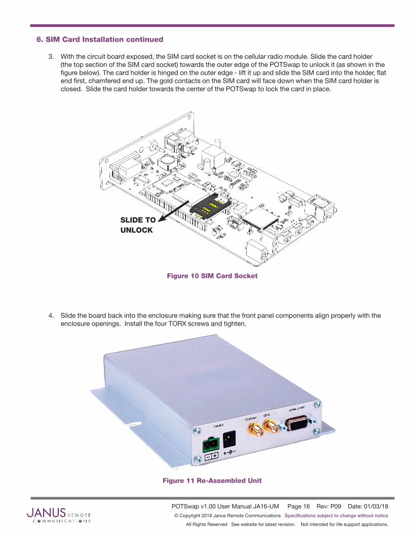
3. With the circuit board exposed, the SIM card socket is on the cellular radio module. Slide the card holder (the top section of the SIM card socket) towards the outer edge of the POTSwap to unlock it (as shown in the figure below). The card holder is hinged on the outer edge - lift it up and slide the SIM card into the holder, flat end first, chamfered end up. The gold contacts on the SIM card will face down when the SIM card holder is closed. Slide the card holder towards the center of the POTSwap to lock the card in place.
4. Slide the board back into the enclosure making sure that the front panel components align properly with the enclosure openings. Install the four TORX screws and tighten.
Figure 10 SIM Card Socket
SLIDE TO UNLOCK
Figure 11 Re-Assembled Unit
POTSwap v1.00 User Manual JA16-UM Page 17 Rev: P09 Date: 01/03/18© Copyright 2018 Janus Remote Communications Specifications subject to change without notice
All Rights Reserved See website for latest revision. Not intended for life support applications.
7. GPS7.1 GPS OperationPOTSwap models have a GPS antenna connector installed on the back plate and offer the ability to provide enhanced location information to emergency (911) operators. A suitable GPS antenna must be used and the antenna must be properly located to receive the GPS signals.
The GPS operation is automatic, and is independent of the cellular radio operation. When the unit has acquired a GPS location fix, the bottom LED on the RSSI indicator will blink several times for 1 second at 10 second intervals. This indication is independent of the cellular signal strength indication. See section 5.1 – Front Panel. A GPS location fix should be available within a few minutes of operation under normal conditions.
7.2 GPS AntennaFor best results, it is recommended that an active GPS antenna be used with the POTSwap. The GPS antenna connector provides a 2.85V bias voltage to power an active antenna, and should easily be able to supply the 5 to 25mA of current that a typical active GPS antenna requires. Any standard off-the-shelf active GPS antenna that will operate at the 2.85V bias voltage should suffice. See section 11 – Accessories.
7.3 GPS Antenna locationThe ideal GPS antenna position would be an outdoors location with a clear view of the sky to the horizon in all directions, with no obstructing structures or foliage. A higher antenna placement usually gives a better view of the sky over surrounding obstructions. In the northern hemisphere, a southern sky view is preferable over a northern sky view. If the antenna must be indoors, placement as near as possible to a window is preferable. Receiving a GPS location fix deep inside buildings or in dense urban environments (“street canyons”) is normally not possible.
7.4 GPS TroubleshootingWith a terminal attached to the SERIAL port, debug messages are available that can be used to monitor the GPS operation. See section 4 – Configuration, for information on attaching a terminal to the SERIAL port.
There are several types of debug messages output during normal operation. The message with the GPS information includes “$GPSACP:” near the beginning of the output line, and is output about once per minute. The $GPSACP message conveys 11 terms, separated by commas:
UTC UTC time (hhmmss.sss)latitude format is ddmm.mmmm N/Slongitude format is ddmm.mmmm E/Whdop x.x - Horizontal Diluition of Precisionaltitude x.x Altitude - mean-sea-level (geoid) in metersfix 0 or 1 - Invalid Fix; 2 - 2D fix; 3 - 3D fixcog ddd.mm - Course over Ground (degrees, True)spkm x.x Speed over ground (Km/hr)spkn x.x- Speed over ground (knots)date ddmmyy Date of Fix.nsat nn - Total number of satellites in use, 00..12
The final term can be used to provide some useful information about the quality of the GPS antenna system being used. Generally, the better the antenna system, the greater the number of satellites will appear in the ‘nsat’ term. Though it varies over time, the typical maximum number of satellites available is 10. A minimum of 4 is required to get a location fix, and numbers of 8 or more indicate an excellent antenna system.
With no location fix, the $GPSACP message will appear as follows:
[$GPSACP: ,,,,,1,,,,,]
This would be expected after the unit has powered up but before a location fix is aquired. It would also be indicative of a poor antenna system if it was still being reported after several minutes of operation.
A typical fix might appear similar to the following:
[$GPSACP: 183117.000,4147.6251N,08815.5097W,1.25,191.0,3,191.69,0.12,0.06,290716,07]
In this example the ‘nsat’ term indicates that 7 satellites are being used.
POTSwap v1.00 User Manual JA16-UM Page 18 Rev: P09 Date: 01/03/18© Copyright 2018 Janus Remote Communications Specifications subject to change without notice
All Rights Reserved See website for latest revision. Not intended for life support applications.
8. SpecificationsInterfaces
Parameters DescriptionModem/Telephone RJ11 connector (FXS)Serial DB9 female DCE connector (user terminal interface for configuration and firmware upload.Cellular Antenna SMA connector, 50 ohms.GPS Antenna 50 ohm SMA w/ 2.85V bias (on TAGFNG models only)Power Input 7-15 Vdc; 22W with two input alternatives: -- 6mm DC power jack with 2mm center pin positive -- 5.08mm (0.200”) terminal block header (accepts screw clamp and crimp connector type terminal blocks)
FeaturesParameters DescriptionSLIC Performs all BORSCHT functions: Battery supply to subscriber line Overvoltage protection Ringing current supply Supervision of subscriber terminal Coder and decoder Hybrid, 2 wire to 4 wire conversion Testing DTMF encoding and decoding REN=5 at 100 ft. (30m)Voice Voice over cellularCellular Connection HSPA910PS model supports GSM/GPRS/EDGE and WCDMA/HSPA. Frequency Bands: GSM / GPRS / EDGE: 850, 900, 1800, 1900 MHz UMTS / HSPA: 800/850, 900, AWS1700, 1900, 2100 MHzSIM Card Mini (2FF size) SIM cardPush Buttons SELECT, MODE, and RESETLEDs Power, Status, Cellular Link and Signal StrengthDimensions (L x W x D) 6.5 in (165mm) x 5.2 in (132mm) x 1.2 in (30mm)Weight 15 oz (425 g)Mounting Integrated mounting brackets (optional)
EnvironmentalParameters DescriptionOperating Temperature -40° C to +60° C (-40° F to 140° F) (Note: Operating temperature may be further limited by specific Plug-In Terminus terminal)Relative Humidity 5% to 95% (non-condensing)
POTSwap v1.00 User Manual JA16-UM Page 19 Rev: P09 Date: 01/03/18© Copyright 2018 Janus Remote Communications Specifications subject to change without notice
All Rights Reserved See website for latest revision. Not intended for life support applications.
9. Compatible Terminal Block Connectors
The POTSwap has a 0.200” terminal block header, also referred to as a 5.08 mm Eurostyle connector. It supports a variety of plug-in terminal block types, including screw terminal, spring contact and crimp terminals.
Manufactures for these terminal blocks include:
• Camden Electronics• FCI Electronics• Molex• OST (On Shore Technology) • Phoenix Contact • TE Connectivity (Tyco/Buchannan)• Weidmüller• Würth Elektronik
Below is a small sample of compatible connectors:
TYPE MANUFACTURER PART NO. DESCRIPTIONScrew Terminal TE Connectivity1 796634-2 vertical screw, horizontal plug TE Connectivity 1986484-2 horizontal screw, vertical plug Molex 395300002 vertical screw, horizontal plug Molex 395332002 horizontal screw, vertical plug Weidmuller 1943580000 vertical screw, horizontal plugSpring Clamp Weidmuller 1013680000 orange Weidmuller 1013430000 blackCrimp Housing & Contacts TE Connectivity 1986160-2 crimp housing, green TE Connectivity 965901-1 crimp terminal, 20-17 AWG TE Connectivity 965899-1 crimp terminal, 13-17 AWG Weidmuller 1610490000 crimp housing, orange Weidmuller 1711960000 crimp housing, black Weidmuller 1604250000 crimp contact, 24-22 AWG Weidmuller 1567060000 crimp contact, 20-17 AWG Weidmuller 1567070000 crimp contact, 16-14 AWG
Note:1-ThiscomponentisavailablefromJanusRemoteCommunications.See‘TERMINALBLOCK’inSection10.
10. Ordering Information
POTSwap MODEL DESCRIPTIONHSPA910PS v1.00 TAUVNG HSPA+/UMTS/EDGE/GPRS/GSM (AT&T and PTCRB)EVDO910PS v2.00 TAUVNG EV-DO (Sprint) EVDO910PS v3.00 TAUVNG EV-DO (Verizon)
11. AccessoriesThe following accessories are available from Janus Remote Communications:
ACCESSORY DESCRIPTION JANUS STORE PART NUMBERPOWER SUPPLY Wall transformer with circular DC connector, 12V 2A MC-0004CELLULAR ANTENNA Indoor 5-band GSM/CDMA/UMTS 3G ANT-0003GPS ANTENNA Active Antenna, Magnetic Mount, Waterproof, 10 ft. SMA ANT-0030
12. References JA03-UM - Terminus Plug-In Products User Manual
Revision History Revision Revision Date NoteP00 11/23/13 Preliminary POTSwap User Manual ReleaseP01 03/03/14 Overall Product Update/ChangesP02 05/08/14 Updated to GSM Version Only (HSPA910PS)P03 08/19/14 Updated Voice Operations and ConfigurationsP04 08/11/15 Update to Enclosure and DimensionsP05 09/05/15 Operation, Configuration & InterfacesP06 08/01/16 Added GPS InformationP07 08/31/16 Added SIM Card SizeP08 07/13/17 Added v2.00 EVDO version to Ordering InformationP09 01/03/18 Updated Part Numbers and Accessories
POTSwap – HSPA910PS v1.00Product User Manual
Division of The Connor-Winfield Corporation2111 Comprehensive Drive • Aurora, Illinois 60505
630.499.2121 • Fax: 630.851.5040
www.janus-rc.com
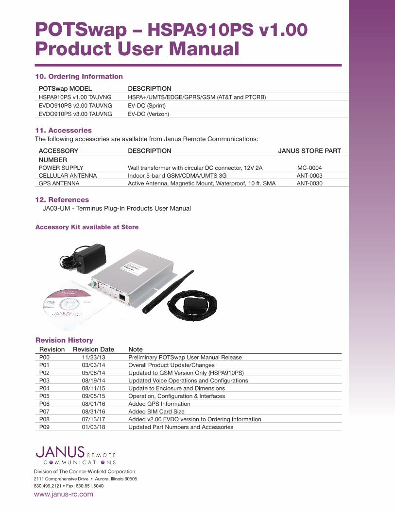
Accessory Kit available at Store