Embed Size (px)
Citation preview

v 8 4 : 1 8 f ; 8 2 "
NASA Contractor Report 172260
8
POSTOP: Postbuckled Open- Stiffener Optimum Panels- User's Manual
S. B. Biggers
J. N. Dickson
LOCKHEED-GEORGIA COMPANY A Divi sion of Lockhced Corpor at ion Mar iet ta, Geor gi a
C o n t r a c t NAS1-15949 January 1984
National Aeronautics and Space Administration
Langley Research Center Hampton, Virginia 23665
https://ntrs.nasa.gov/search.jsp?R=19840010614 2018-01-31T07:41:21+00:00Z
FOREWORD
This r e p o r t is prepared by t h e Lockheed-Georgia Company under c o n t r a c t
NASI-15949, "Advanced Composite S t r u c t u r a l De'sign Technology for Commercial
T ranspor t Aircraft," and s e r v e s as a user's manual for a computer program
prepared for t h e a n a l y s i s and s i z i n g o f s t i f f e n e d composi te pane l s . T h i s
work was performed under Task Assignment No. 5 o f t h e c o n t r a c t . The pro-
gram, is sponsored by t h e Na t iona l Aeronaut ics and Space Admin i s t r a t ion , Langley Research Center (NASA/LaRC). Dr. James H. S t a r n e s is t h e Project
Engineer f o r NASA/LaRC. John N . Mckson i s t h e Program Manager f o r t h e Lockheed-Georgia Company.
In a d d i t i o n to t h e a u t h o r s t h e fo l lowing Lockheed s p e c i a l i s t / c o n s u l t - a n t s made major c o n t r i b u t i o n s to t h e m a t e r i a l p re sen ted .
L. w. Liu hogramming
Dr. J. T. S. Wang (Georgia Tech.) Analysip I
i
S UMMAR Y
INTRODUCTION
SCOPE OF POSTOP
Geometry
Loading Cond i t ions
An a1 y s i s
S i z ing
PROGRAM OPERATION
USE OF PROGRAM
S i z i n g Data
Analys is Data
Comments on S e l e c t e d I n p u t Data ou tpu t
EXAMPLES
1
1
2
2
8
a 13 16
22
' 29
32
REFERENCES
ii
95
POSTOP: - Postbuckled - Open-STiffener - - Optimum - P a n e l s - User's Manual
S h e r r i l l B. Bigger s and John N, Dickson
Lockheed-Georgia Company
Marietta, Georgia
I n s t r u c t i o n s f o r t h e u s e of t h e computer program POSTOP for t h e a n a l y s i s o r s i z i n g o f s t i f f e n e d p a n e l s a r e d e s c r i b e d . The panel i s
s t i f f e n e d wi th l o n g i t u d i n a l , open-sec t ion s t i f f e n e r s . Composite m a t e r i a l s may be used. S t i f f n e s s , s t a b i l i t y and s t r e n g t h a n a l y s e s are performed.
S i z i n g o f t h e pane l geometry and l a m i n a t e c o n f i g u r a t i o n s may be performed. This r e p o r t serves a s a User's Manual f o r POSTOP.
INTRODUCTION
The computer program POSTOP h a s been developed t o serve as an a i d i n
t h e a n a l y s i s and optimum s i z i n g o f s t i f f e n e d pane l s . This a n a l y s i s and s i z i n g code was developed s p e c i f i c a l l y f o r l o n g i t u d i n a l l y s t i f f e n e d compo-
s i te p a n e l s loaded i n t h e pos tbuck l ing range . Buckling res is tant p a n e l s , o r p a n e l s made of i s o t r o p i c m a t e r i a l s may also be t r e a t e d i f t h e assump-
t i o n s and a n a l y t i c a l t e c h n i q u e s o u t l i n e s i n Reference 1 a r e a p p r o p r i a t e f o r
t h e p a r t i c u l a r a p p l i c a t i o n . In summary, POSTOP may be used to ana lyze o r
s ize p a n e l s made o f l i n e a r e l a s t i c m a t e r i a l s wi th c o n f i g u r a t i o n s normal ly
found i n f u s e l a g e , wing, o r empennage cove r s .
Th i s r e p o r t g i v e s a g e n e r a l d e s c r i p t i o n o f t h e c a p a b i l i t i e s and
l i m i t a t i o n s o f t h e code. D e t a i l e d i n s t r u c t i o n s r e q u i r e d t o use t h e program
a r e p re sen ted . S e v e r a l example problems a r e inc luded . An unders tanding of
t h e a n a l y t i c a l and s i z i n g procedures desc r ibed i n Reference 1 w i l l a i d i n
t h e e f f e c t i v e u s e o f t h e code.
1
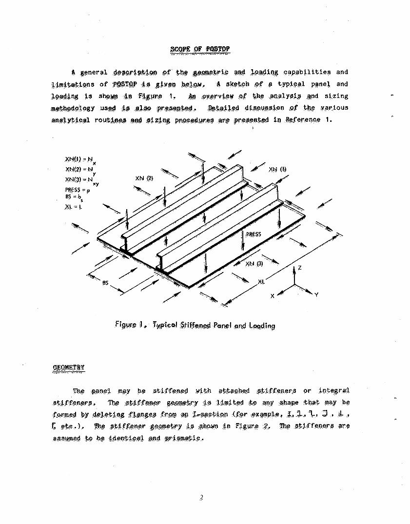
A general ib
.2
n
I I I
I C = CENTROID S = SHEAR CENTER
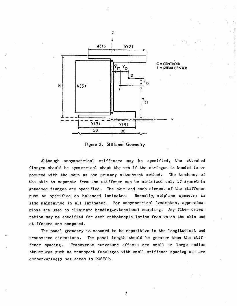
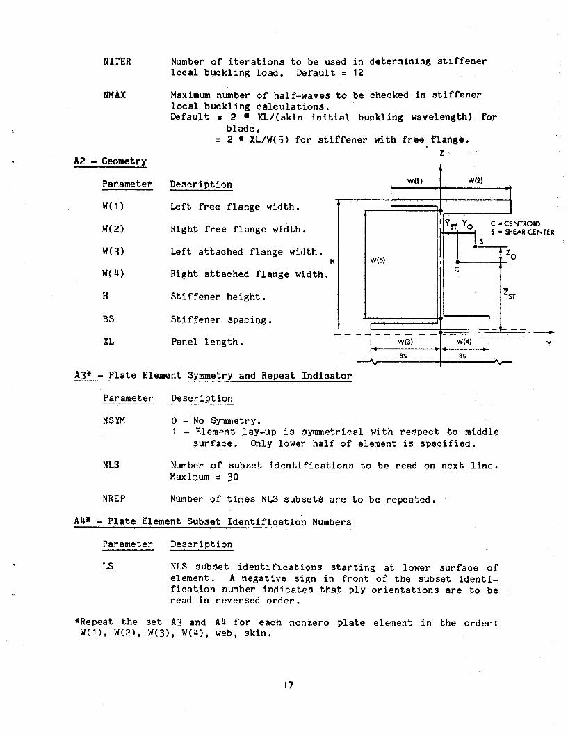
Figure 2. Stiffene'r Geometry
Although unsymmetr ical s t i f f e n e r s may be s p e c i f i e d , t h e a t t a c h e d
f l a n g e s s h o u l d be symmetr ica l about t he web i f t h e s t r i n g e r i s bonded to or
cocured wi th t h e s k i n a s t h e pr imary a t t achmen t method. The tendency of
t h e s k i n to s e p a r a t e from t h e s t i f f e n e r can be minimized o n l y if symmetric
a t t a c h e d f l a n g e s a r e s p e c i f i e d . The s k i n and each e lement of t h e s t i f f e n e r
must be s p e c i f i e d a s ba l anced l a m i n a t e s . Normally, midplane symmetry i s
a l s o main ta ined i n a l l l a m i n a t e s . For unsymmetr ical l a m i n a t e s , approxima-
t i ons a r e used to e l i m i n a t e bending-extens iona l coup l ing . Any f iber o r i e n -
t a t i o n may be s p e c i f i e d for each o r t h o t r o p i c lamina from which t h e s k i n and s t i f f e n e r s a r e composed.
The panel geometry i s assumed t o be r e p e t i t i v e i n t h e l o n g i t u d i n a l and t r a n s v e r s e d i r e c t i o n s . The panel l e n g t h should be g r e a t e r t h a n t h e stif-
f e n e r spac ing . T ransve r se c u r v a t u r e effects a r e sma l l i n l a r g e r a d i u s
s t r u c t u r e s such a s t r a n s p o r t f u s e l a g e s with smal l s t i f f e n e r spac ing and a r e
c o n s e r v a t i v e l y n e g l e c t e d i n POSTOP.
3
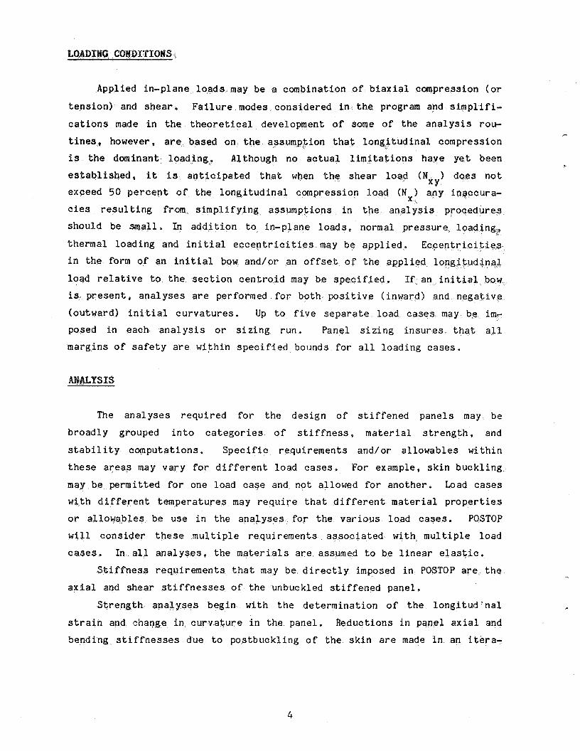
LOADING CONDITIONS
Applied in-p lane l o a d s may be a combina on of b i a x i a l c
t e n s i o n ) and s h e a r . F a i l u r e mo cons ide red i n t m and s i m p l i f i -
cations made i n t h e t h e o r e t i c a l development o f some of t h e a n a l y s i s rou -
t i n e s , howeve n t h a t l o n g i t u d i n is t h e domina
e s t a b l i s h e d , it is a n t i c i p a t e d t h a t when t h e shear 1
exceed 50 p e r c e n t of t h e lon i t u d i n a l compression
cies r e s u l t i n g from s i m p l i f y i n g assumpt ions i n t h e a n a l y s i s procedure
should be 1. In a d d i t i o n t o in-plane l o a d s , normal p r e s s u r e l o a d i n
the rma l load ing and i n i t i a l eccentr ic i t ies may be a p p l i e d . Eccentriciti i n t h e form of an i n i t i a l bow and/or an o f f s e t o f t h e a p p l i e d l o n g i t u d i
load r e l a t i v e to t h e s e c t i o n c e n t r o i d may be s p e c i is p r e s e n t , a n a l y s e s are performed f o r both posit ive ( inward) and ne&
(outward) i n i t i a l c u r v a t u r e s . Up t o f i v e s e p a r a t e load c a s e s mgy be i m - posed i n each a n a l y s i s o r s i z i n g r u n . Panel s i z i n g insures t h a t aJ.1
margins o f s a f e t y a r e wi th in s p e c i f i e d bounds f o r a l l l oad ing c a s e s .
SIS
The a n a l y s e s r e q u i r e d f o r t h e des ign o f s t i f f e n e d p a n e l s may be
b road ly grouped i n t o c a t e g o r i e s o f s t i f f n e s s , m a t e r i a l s t r e n g t h , and
s t a b i l i t y c o g p u t a t i o n s , S p e c i f i c r equ i r emen t s and/or a l l o w a b l e s wi th in
t h e s e a r e a s may v a r y f o r d i f f e r e n t l oad c a s e s . For example, s k i n buck l ing -
may be pe rmi t t ed f o r one load c a s e and no t allowed f o r ano the r . Load c a s e s
wi th d i f f e r e n t t empera tu res may r e q u i r e t h a t d i f f e r e n t m a t e r i a l p r o p e r t i e s
o r a l l o w a b l e s be use i n t h e a n a l y s e s f o r t h e v a r i o u s load cases. POSTOP
w i l l c o n s i d e r t h e s e m u l t i p l e r equ i r emen t s a s s o c i a t e d wi th m u l t i p l e l oad
c a s e s . In a l l a n a l y s e s , t h e m a t e r i a l s a r e assumed t o be l i n e a r e l a s t i c .
S t i f f n e s s r equ i r emen t s t h a t may be d i r e c t l y imposed i n POSTOP a r e t h e
a x i a l and shea r s t i f f n e s s e s o f t h e unbuckled s t i f f e n e d panel .
S t r e n g t h a n a l y s begin with t h e d e t e r m i n a t i o n o f t h e l o n g i t u d ' n a l
s t r a i n and change i n t curvature i n t h e p a n e l . Reduct ions i n pan
bending s t i f f n e s s e s d u e t o pos tbuck l ing o f t h e s k i n a r e made i n an i t e r a -
4
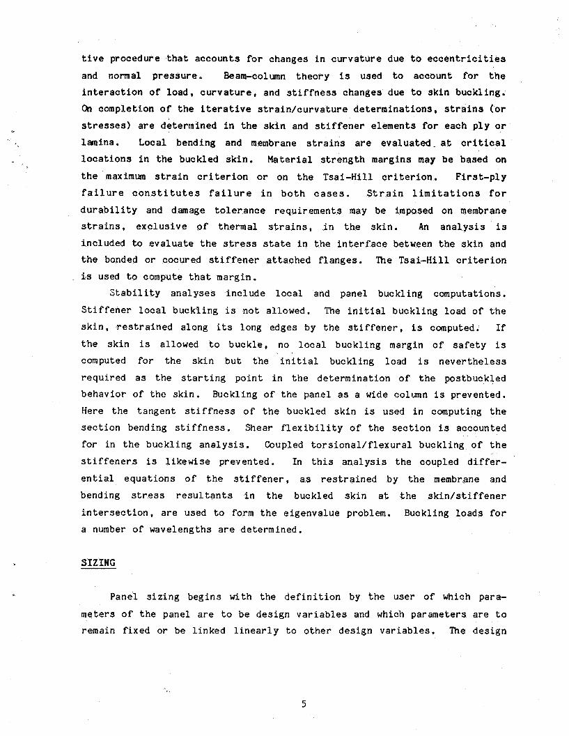
t i v e procedure t h a t a c c o u n t s for changes i n c u r v a t u r e due t o e c c e n t r i c i t i e s
and normal p r e s s u r e . Beam-column t h e o r y is used to account for t h e
i n t e r a c t i o n of load , c u r v a t u r e , and s t i f f n e s s changes due t o s k i n buckl ing . On comple t ion of t h e i t e r a t i v e s t r a i n / c u r v a t u r e d e t e r m i n a t i o n s , s t r a i n s (or stresses) are de termined i n t h e s k i n and s t i f f e n e r e l emen t s for each p l y or lamina. Local bending and membrane s t r a i n s are e v a l u a t e d - a t c r i t i ca l l o c a t i o n s i n t h e buckled s k i n . Material s t r e n g t h margins may be based on t h e maximum s t r a i n c r i t e r i o n or on t h e Tsa i -Hi l l c r i t e r i o n . F i r s t - p l y
f a i l u r e c o n s t i t u t e s f a i l u r e i n b o t h cases . S t r a i n l i m i t a t i o n s f o r d u r a b i l i t y and damage t o l e r a n c e r equ i r emen t s may be imposed o n membrane s t r a i n s , e x c l u s i v e of thermal s t r a i n s , i n t h e s k i n . An a n a l y s i s is inc luded to e v a l u a t e t h e stress s t a t e i n t h e i n t e r f a c e between the s k i n and t h e bonded or cocured s t i f f e n e r attached f l a n g e s . ?he Tsa i -Hi l l c r i t e r i o n
is used t o compute t h a t margin . S t a b i l i t y a n a l y s e s i n c l u d e loca l and panel buck l ing computa t ions .
S t i f f e n e r l oca l b u c k l i n g is n o t allowed. The i n i t i a l b u c k l i n g load of t h e
s k i n , r e s t r a i n e d a long its long edges by t h e s t i f f e n e r , is computed. If
t h e s k i n is allowed t o b u c k l e , no loca l b u c k l i n g margin of s a f e t y i s computed for t h e s k i n b u t t h e i n i t i a l buck l ing load i s n e v e r t h e l e s s
r e q u i r e d a s t h e s t a r t i n g p o i n t i n t h e d e t e r m i n a t i o n of t h e pos tbuckled behav io r of t h e s k i n . Buckl ing of t h e p a n e l a s a wide column i s prevented .
Here t h e t a n g e n t s t i f f n e s s of t h e buckled s k i n is used i n computing t h e
s e c t i o n bending s t i f f n e s s . Shear f l e x i b i l i t y of t h e s e c t i o n is accounted
for i n t h e b u c k l i n g a n a l y s i s . Coupled t o r s i o n a l / f l e x u r a l b u c k l i n g of t h e
s t i f f e n e r s is l i k e w i s e prevented . In t h i s a n a l y s i s t h e coupled d i f fe r -
e n t i a l e q u a t i o n s o f t h e s t i f f e n e r , a s r e s t r a i n e d by t h e membrane and
bending stress r e s u l t a n t s i n t h e buckled s k i n a t t h e s k i n / s t i f f e n e r
i n t e r s e c t i o n , are used t o form t h e e i g e n v a l u e problem. Buckl ing loads for
a number of wavelengths a re de termined .
S I Z I N G
Pane l s i z i n g b e g i n s wi th t h e d e f i n i t i o n by t h e u s e r of which para-
meters of t h e p a n e l are t o be d e s i g n v a r i a b l e s and which parameters are t o remain f i x e d o r be l i n k e d l i n e a r l y t o o the r d e s i g n v a r i a b l e s . The d e s i g n
5
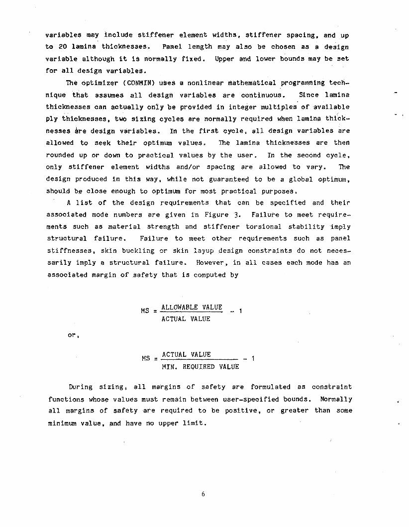
v a r i a b l e s ma i n c l u d e s t i f f e n e r e lement w id ths s t i f f e n e r s p a c i n g , and up t o 20 lamina t h i c k n e s s e s . Panel l e n g t h may a l s o be chosen a s a d e s i g n
v a r i a b l e a l t h o u g h it is norma l ly f i x e d , Upper and lower bounds may be se t f o r a l l d e s i g n v a r i
N) u s e s a n o n l i n e a r mathematical p ro amming tech-
n i q u e t h a t a s s s a l l d e s i g n v a r i a b l e s a re t i n u o u s . % n e e lamina t h i c k n e s s e s can a c t u a l l y ided i n i n t e g l t i p l e s - of a v a i l a b l e p l y t h i c k n e s s e s , two s i z i e normal ly re lamina th i ck -
n e s s e s Are d e s i g n v a r i a b l e s . n v a r i a b l e s a r e
allowed to seek t h e i r optimum v a l u e s . The lamina esses a r e t h e n
rounded up o r down t o p r a c t i c a l v a l u e s by t h e user. I n t h e second c o n l y s t i f f e n e r element wid ths and/or spac ing are allowed t o vary .
d e s i g n produced i n t h i s way, wh i l e n o t guaranteed to be a g l o b a l o p t
should be c l o s e enough to optimum f o r most p r a c t i c a l pu rposes ,
In t h e first c y c l e , a l l
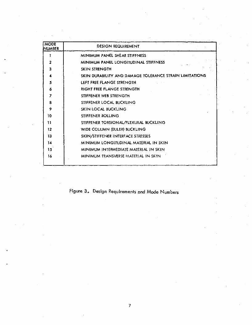
A l ist o f t h e d e s i g n r equ i r emen t s t h a t can be s p e c i f i e d and their
a s s o c i a t e d mode numbers a r e g iven i n F igu re 3. F a i l u r e t o meet require-
m e n t s such a s m a t e r i a l s t r e n g t h and s t i f f e n e r t o r s i o n a l s t a b i l i t y imply s t r u c t u r a l f a i lu re . F a i l u r e t o meet o t h e r r equ i r emen t s such a s pane l
stiffnesses, s k i n buck l ing a- s k i n l a y u p des ign c o n s t r a i n t s d o no t n s a r i l y imply a s t r u c t u r a l f a i l u r e . However, i n a l l c a s e s each mode h a s an
a s s o c i a t e d margin o f s a f e t y t h a t i s computed by
- 1 ALLOWABLE VALUE
ACTUAL VALUE MS =
- 1 ACTUAL VALUE MS 2
I N , R E Q U I R E D VALUE
s i z i n g , a l l marg ins of s a f e t y a r e formula ted a s c o n s t r a i n t
f u n c t i o n s whose v a l u e s must remain between use r - spec i f i ed bounds. Normally a l l margins o f s a f e t y a r e r e q u i r e d t o be p o s i t i v e , o r g r e a t e r than some
minimum v a l u e , and have no upper l i m i t .
6
MODE NUMBER
1
2
3
4
5
6
7
8
9
10
11
12
13 14
15
16
DESIGN REQUIREMENT
MINIMUM PANEL SHEAR STIFFNESS
MINIMUM PANEL LONGITUDINAL STIFFNESS
SKIN STRENGTH
SKIN DURABILITY AND DAMAGE TOLERANCE STRAIN LIMlTATlONS
LEFT FREE FLANGE STRENGTH
RIGHT FREE FLANGE STRENGTH
STIFFENER WEB STRENGTH
STIFFENER LOCAL BUCKLING
SKIN LOCAL BUCKLlNG
STIFFENER ROLLING
STIFFENER TORSIONAL/FLEXURAL BUCKLING
WIDE COLUMN (EULER) BUCKLING
SKlN/STlFFENER INTERFACE STRESSES
MINIMUM LONGITUDINAL MATERIAL IN SKlN
MINIMUM INTERMEDIATE MATERIAL IN SKIN
MINIMUM TRANSVERSE MATER!& IN SKlN
Figure 3, Design Requirements and Made Numbers
7
P
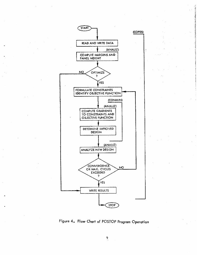
A flow char t of t h e b a s i c o p e r a t i o n s i n POSTOP is shown i n F i g u r e 4.
The program is composed o f three major routines: COPES, CONMIN a
COPES serves a s t h e main program,
r ead a n a l y s i s data . Data is o u t p u t a s s p e c i f i e d by t h e user. COPES c a l l s
ANALIZ t o compute margins of s a f e t y o b j e c t i v e f u n c t i o n v a l u e s . If o n l y
It reads s i z i n g data and
a s i n g l e a n a l y s i s is s p e c i f i e d , r e s u l t s are o u t p u t and c o n t r o l returns t o t h e user. If s i z i n g is des i o rmula t e s t h e margins o f s a f e t y
i n proper constraint form and c a l l s t o c a l c u l a t e g r a d i e n t s t o t h e c o n s t r a i n t s and o b j e c t i v e f u n c t i o n . CONMIN does t h i s by c a l l i n g ANALIZ for
d e s i g n s i n which a l l v a r i a b l e s a r e s l i g h t l y changed one a t a time. Based on t h i s i n f o r m a t i o n , CONMIN de t e rmines an improved des ign . A N A L I Z is called aga in and convergence of t h e o p t i m i z a t i o n procedure is checked, The
s i z i n g p rocess c o n t i n u e s u n t i l convergence t o an optimum des ign is achieved
or t h e maximum number o f c y c l e s is exceeded. Results a r e o u t p u t and c o n t r o l r e t u r n s t o t h e user. The COPES/CONMIN programs a r e d e s c r i b e d i n
d e t a i l i n References 2 and 3. The r o u t i n e s composing A N A L I Z a r e desc r ibed i n Reference 1.
USE OF PR
POSTOP can be used t o perform an a n a l y s i s o f a s p e c i f i c pane l o r t o
s i z e an optimum pane l s t a r t i n g from an i n i t i a l des ign . The COPES program
h a s c a p a b i l i t i e s beyond t h e s i n g l e a n a l y s i s o r s i z i n g o p t i o n s used i n
POSTOP. These c a p a b i l i t i e s i n c l u d e s e n s i t i v i t y a n a l y s i s , two-var iab le
f u n c t i o n space a n a l y s i s , optimum s e n s i t i v i t y a n a l y s i s , and o p t i m i z a t i o n
u s i n g approximation t e c h n i q u e s . The r o u t i n e s r e q u i r e d t o perform t h e s e a d d i t i o n a l o p t i o n s a r e a v a i l a b l e i n t h e POSTOP sys t em, However, use o f
POSTOP i n o n l y t h e a n a l y s i s o r o p t i m i z a t i o n modes i s descr ibed he re . Reference 2 d e s c r i b e s t h e a d d i t i o n a l i n p u t r e q u i r e d and t h e a p p l i c a t i o n o f
t h e a d d i t i o n a l o p t i o n s i n COPES.
The i n p u t required t o o p e r a t e POSTOP may be d iv ided i n t o two major
s e c t i o n s : s i z i n g data and a n a l y s i s d a t a , Each d a t a set c o n s i s t s o f a sequence o f l o g i c a l f ree-form i n p u t r e c o r d s . Normally each record is a
l i n e o f d a t a or a d a t a c a r d , a l though it is p o s s i b l e t o p l a c e m u l t i p l e ,
8
c
(CONMIN) I
START =-.I
COMPUTE GRADIENTS TO CONSTRAINTS AND OBJECTIVE FUNCTION
t
t READ AND WRITE DATA
(ANALIZ)
COMPUTE MARGINS AND PANEL WEIGHT
DETERMINE IMPROVED DESIGN -
(COPES 7
FORMULATE CONSTRAINTS I IDENTIFY OBJECTIVE FUNCTION
I I
ANALYZE NEW DESIGN ANALYZE NEW DESIGN
Figure 4. Flow Chart of POSTOP Program Operation
9
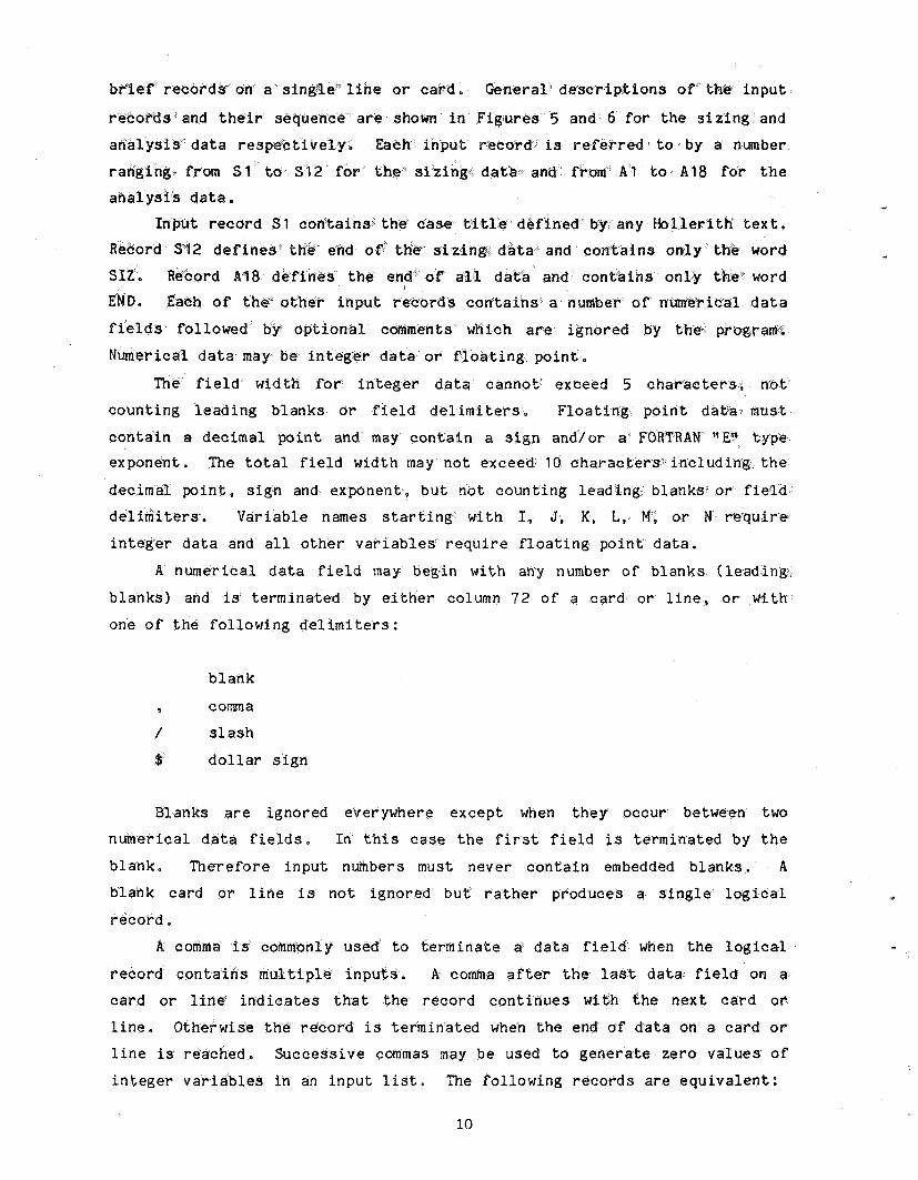
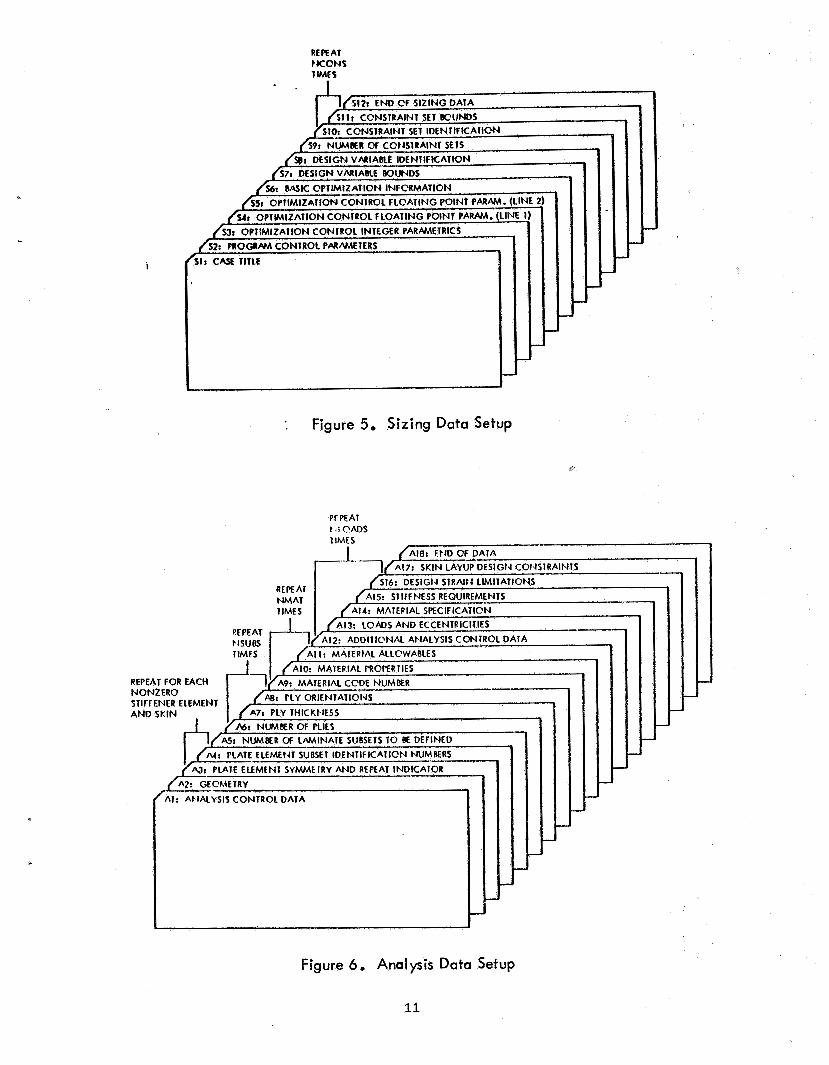
bi-ief rec on" a ' s i n g l e l i n e or card. p t i o n s of' the i n p u t
rd s and t h e i r sequene a r e shown i n F i g u r e s 5 and 6 for t h e s i z i n g and
a n a l y s i s d a t a r e s p e c t i v e l y . i n p u t record is ref r e d i t o by a number
s i z i n g d a t a a from A'1 t o A 1 8 for the
e d e f i n e d by any H o l l e r i t h text . ord S12 d e f data and c o n t a i
a t a and c o n t a i n s o Each of t h e - other i n p u t r of numer i ca l d a t a
f i e lds followed by o p t i o n a l comments which a r e ignored by t h e program.
i c a l d a t a may be i n t e g e r d a t a or f l o a t i n g p o i n t .
The f i e l d wid th for i n t e g e r d a t a cannoth exceed 5 char'ae
coun t ing l e a d i n g b l a n k s or f i e l d delimiters. F l o a t i n g p o i n t da t a :
c o n t a i n a dec imal p o i n t and may c o n t a i n a s i g n and/or a FORTRA t y p e exponent . The t o t a l f i e l d w i d t h may n o t exceed 10 c h a r a c s i n c l u d i n g + t h e
dec imal p o i n t , s i g n and exponent , b u t not coun t ing l e a d i n g b l anks - o r f i e
del imiters . Variable names s t a r t i n g w i t h I, J, K, L, M, or N requir .e
i n t e -ge r d a t a and a l l other v a r i a b l e s r e q u i r e f l o a t i n g p o i n t d a t a .
A numer i ca l d a t a f i e l d may begin wi th ahy number o f b l a n k s ( l e a d i n g
b l a n k s ) and is t e rmina ted by e i ther c o l u m n 72 o f a c a r d o r l i n e , o r w i t h
one of t h e f o l l o w i n g delimiters:
b l a n k
9 comma / s l a s h
$ d o l l a r s i g n
Blanks a r e ignored everywhere except when they occur between two
numer i ca l d a t a f i e l d s . In t h i s c a s e t h e f i r s t f i e l d i s t e rmina ted by t h e
b l ank . The re fo re i n p u t numbers m u s t never c o n t a i n embedded b lanks . A
blank card or l i n e is n o t ignored b u t r a t h e r produces a s i n g l e l o g i c a l
record
to t e r m i n a t e a d a t a f i e l d when t h e l o g i c a l
t i p l e i n p u t s . A comma a f t e r t h e l a s t data f i e l d on a c a r d o r l i n e indicates t h a t t h e record c o n t i n u e s w i t h t h e n e x t card o r
l i n e . Otherwise record i s terminated when t h e end of d a t a on a ca rd or l i ne is reach . S u c c e s s i v e cmrnas may be used t o g e n e r a t e z e r o v a l u e s of
i n t e g e r v a r i a b l e s i n an i n p u t l i s t . The fo l lowing r e c o r d s a r e e q u i v a l e n t :
10
c
i
REfTAI NCONS IMCS
: Figure 5, Sizing Data Setup
J
P
J
J
Figure 6. Analysis Data Setup
11
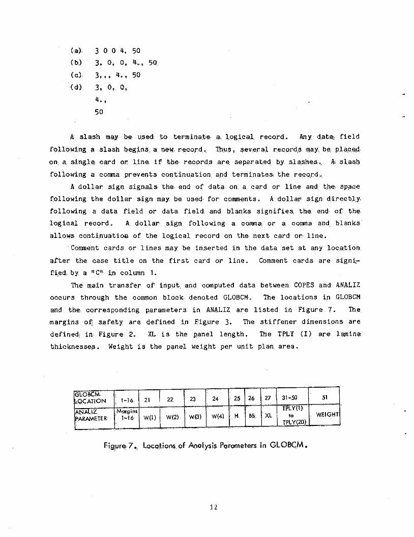
s l a s h may used. to term . Any d a t a , f i e l d
f o l l o n i n g a s l a s h beg ins a new r-ecord. Thus, several r e c o r d s plape;d on a single card o r l i n e i f t h e records are s a r a t e d by s l a s h e s . 4. s l a s h
fo l lowing a comma p r e v e n t s c o n t i n u a t i o n and terminatesl t h e r eco rd e
A d o l l a r s i g n s i g n d s t h e end o f d a t a on a c a r d o r l ine and t h e spgGe fo l lowing t h e d o l l a r si n may be used f o r comments. A d o l l a r sign d i r e c b l y
fol l .owing a d a t a f i e l d o r d a t a f i e l d and b l anks s i g n i f i e s , t h e end o f
l o g i c a l r eco rd . A d o l l a r s i g n fo l lowing a comma o r a comma b lanks
allows c o n t i n u a t i w o f t h e l o g i c a l r eco rd on t h e n e x t c a r d o r l i n e .
Comment c a r d s o r l ines may i n s e r t e d i n t h e d a t a s e t a t any l o c
after t h e c a s e t i t l e on t h e f i r s t ca rd or l i n e . Comment c a r d s a r e signi-
, by a *!C" i n column 1.
The main t r a n s f e r o f i n p u t and computed d a t a between COPES and A N A L I Z
o c c u r s th rough t h e common b l o c k denoted GLOBCM. The l o c a t i o n s i n GLOBCM
and t h e cor responding parameters i n ANALIZ a r e l i s t e d i n F igu re 7. The
margins o f s a f e t y a r e de.fined i n F igu re 3. The s t i f f e n e r d imens ions a r e
d e f i n e d i n F igu re 2. XL i s t h e pane l l e n g t h . The TPLY ( I ) a r e lamina
t h i c k n e s s e s . Weight is t h e pane l weight per u n i t p lan a r e a .
Parameters in GLOBCM e
3.2
i
, i
I
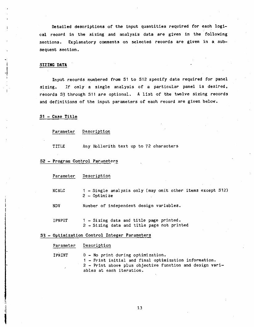
Deta i l ed d e s c r i p t i o n s of t h e i n p u t q u a n t i t i e s r e q u i r e d for each l o g i -
cal record i n t h e s i z i n g and a n a l y s i s d a t a a r e g iven i n t h e f o l l o w i n g
s e c t i o n s . Explana tory comments on selected records a r e g iven i n a sub-
sequent s e c t i o n .
S I Z I N G DATA
I n p u t records numbered from S1 t o $12 s p e c i f y data r e q u i r e d for panel s i z i n g . If o n l y a s i n g l e a n a l y s i s o f a p a r t i c u l a r pane l is desired,
r e c o r d s S3 t h r o u g h S11 a r e o p t i o n a l . A l i s t of t h e twelve s i z i n g r e c o r d s and d e f i n i t i o n s o f t h e i n p u t pa rame te r s o f each r e c o r d are g iven below.
S1 - Case T i t l e
Parameter D e s c r i p t i o n
TITLE Any Holler i th t ex t up t o 72 c h a r a c t e r s
S2 - Program C o n t r o l Parameters .-
Parameter D e s c r i p t i o n
NCALC 1 - S i n g l e a n a l y s i s o n l y (may omit o t h e r items excep t S12) 2 - Optimize
NDV Number o f independent d e s i g n v a r i a b l e s .
IPNPUT 1 - S i z i n g d a t a and t i t l e page p r i n t e d . 2 - S i z i n g d a t a and t i t l e page not p r i n t e d
S3 - Opt imiza t ion C o n t r o l I n t e g e r Parameters
Parameter D e s c r i p t i o n
IPRINT 0 - No p r i n t d u r i n g o p t i m i z a t i o n . 1 - P r i n t i n i t i a l and f i n a l o p t i m i z a t i o n in fo rma t ion . 2 - P r i n t above p l u s o b j e c t i v e f u n c t i o n and des ign v a r i - a b l e s a t each i t e r a t i o n .
13
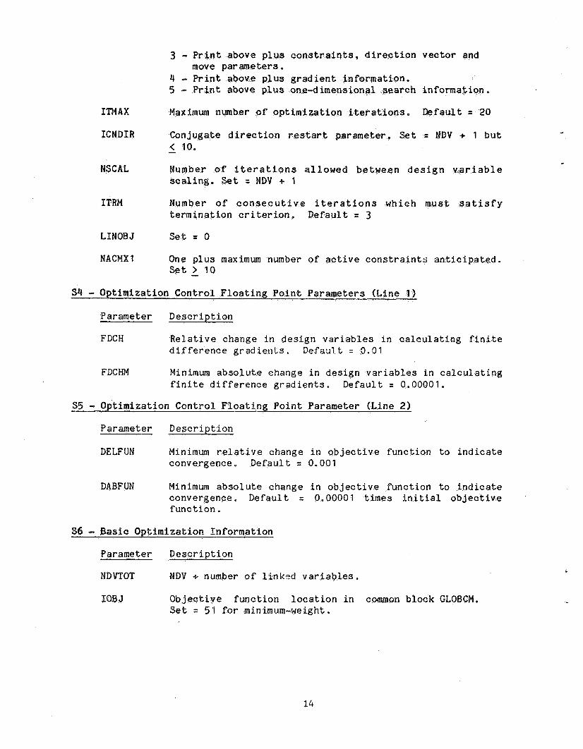
t above p l u s c o n s t r a i n t s , d i r e c t i o n v e c t o r and pa rame te r s .
4 - P r i n t above p l u s g r a d i e n 5 - P r i n t above p l u s one-dim h i n f o r m a t i o n ,
I T M A X Maximum number of o p t i m i z a t i o n i t e r a . I l e f a u l t = 20
I C N D I R a r t parameter . Set = NDV 4 1 b u t -
GAL Number of i c e r a t i o n s allowed b e t i g n v a r i a b l e . Set = HDV + 1
ITRM Number of c o n s e c u t i v e i t e r a t i o n s w h i c h t s a t i s f y t e r m i n a t i o n c r i t e r i o n . D e f a u l t = 3
LINOBJ Set = 0
NACNX 1 One p l u s maximum number of a c t i v e c o n s t r a i n t s a n t i c i p a t e d . Set - > 10
Parameter D e s c r i p t i o n
FDCH R e l a t i v e change i n d e s i g n v a r i a b l e s i n c a l c u l a t i n g f i n i t e d i f f e r e n c e g r a d i e n t s . Defaa1.t = 0.01
FDCHN Minimum a b s o l u t e change i n d e s i g n va r i ab le s i n c a l c u l a t i n g f i n i t e d i f f e r e n c e g r a d i e n t s . Defaul t = 0.00001.
i z a t i o n C o n t r o l F l o a t i n g P o i n t Parameter (L ine 2)
Pararnet er D e s c r i p t i o n
DELF UN Minimum r e l a t i v e change i n o b j e c t i v e f u n c t i o n t o i n d i c a t e convergence. Defaul t = 0.001
DABFUN Minimum absolu te change i n o b j e c t i v e f u n c t i o n t o i n d i c a t e convergence. D e f a u l t = 0,00001 times i n i t i a l o b j e c t i v e f u n c t i o n .
Parameter D e s c r i p t i o n
NDVTOT NDV 4 number of l i n k e d v a r i a b l e s .
IOB J n i n common b lock G
L
14
A
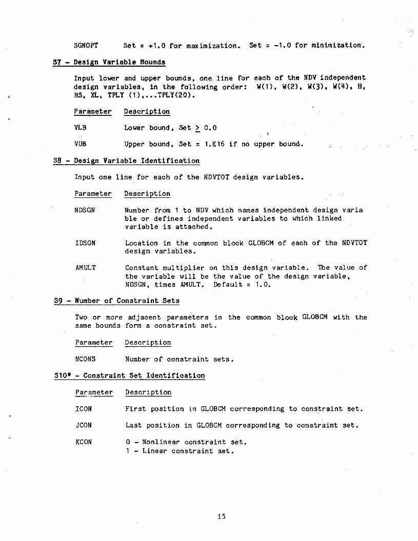
NDSGN Number from 1 t o NDV which names independent des ign v a r i a b le o r d e f i n e s independent v a r i a b l e s to which l i n k e d v a r i a b l e is a t t a c h e d .
I D S G N Locat ion i n t h e common b lock GLOBCM of each o f t h e NDVTOT d e s i g n v a r i a b l e s .
AM ULT Cons tan t m u l t i p l i e r on t h i s d e s i g n v a r i a b l e . The va lue of t h e v a r i a b l e w i l l be t h e v a l u e o f t h e des ign v a r i a b l e , NDSGN, times AMULT. D e f a u l t = 1.0.
S9 - Number o f C o n s t r a i n t Sets
Two o r more a d j a c e n t pa rame te r s i n t h e common b lock GLOBCM wi th t h e same bounds form a c o n s t r a i n t set.
Parameter D e s c r i p t i o n
SGNOPT S e t = +1.0 fo r maximizat ion. Set = -1.0 for minimizat ion.
97 - Design Variable Bounds
Inpu t lower and upper bounds, one l i n e f o r each of t h e NDV independent d e s i g n v a r i a b l e s , i n t h e fo l lowing order: W(l), W(2), W(3). W(4), H, BS, XL, TPLY (1 1,. . .TPLY(20).
Parameter D e s c r i p t i o n
VL B Lower bound, Set - > 0.0
VUB Upper bound, Set = 1.E16 i f no upper bound. I
S8 - Design V a r i a b l e I d e n t i f i c a t i o n
Inpu t one l i n e f o r each of t h e NDVTOT d e s i g n v a r i a b l e s .
Parameter D e s c r i p t i o n
NCONS Number o f c o n s t r a i n t sets.
SlO* - C o n s t r a i n t Set I d e n t i f i c a t i o n
Parameter D e s c r i p t i o n -- ICON F i r s t p o s i t i o n i n GLOBCM co r re spond ing t o c o n s t r a i n t set.
JCON Las t p o s i t i o n i n GLOBCM co r re spond ing to c o n s t r a i n t se t .
KC ON 0 - Nonlinear c o n s t r a i n t set. 1 - Linea r c o n s t r a i n t set .
15
Parameter Description
und S
BU Upper bound set . Set = s1.0 if no upper nd a
and S11 f6r se'es.
Par a met e r
s I 2 I n p u t t he word SI2 ng i n colufin 1'.
ANALYSIS DATA
I n p u t r e c o r d s numbered from A I t o A18 &Z.pecify t h e
a n a l y z e a p a r t i c u l a r pane l . This d a lso d e f i n e s t h e
serves a s a s t a r t i n g po'int for t h e s i z i n g process , . I n c l u d e d ffii Mesa
records are' d a t a s p e c i f y i n g the' pane l g,eometrp, l a m i n a t e des igns , m'agterllal parameters l o a d i n g c o n d i t i o n s , d e s i g n r e q u i e n t s , and a n a l y s i s c'ontrols.,
A list o f t h e 18 a n a l y s i s r e c o r d s and d e f f n i t i o n s of t h e i n p u t pa'ramete
o f each record are given below.
Par a meter D e s c r i p t i d n
IWRITE 0 - Minimum a n a l y s i S p r i n t o u t . Use d u r i n g o p t i m i z a t i o n . 1 - Maximum a n a l y s i s p r i n t o Q t . Do no t use d u r i n $ op t imi -
za t i o n .
NLOADS Number of load c a s e s . Maximum = 5
NMAT Number of mater ia ls to be defined; Maximum = 10
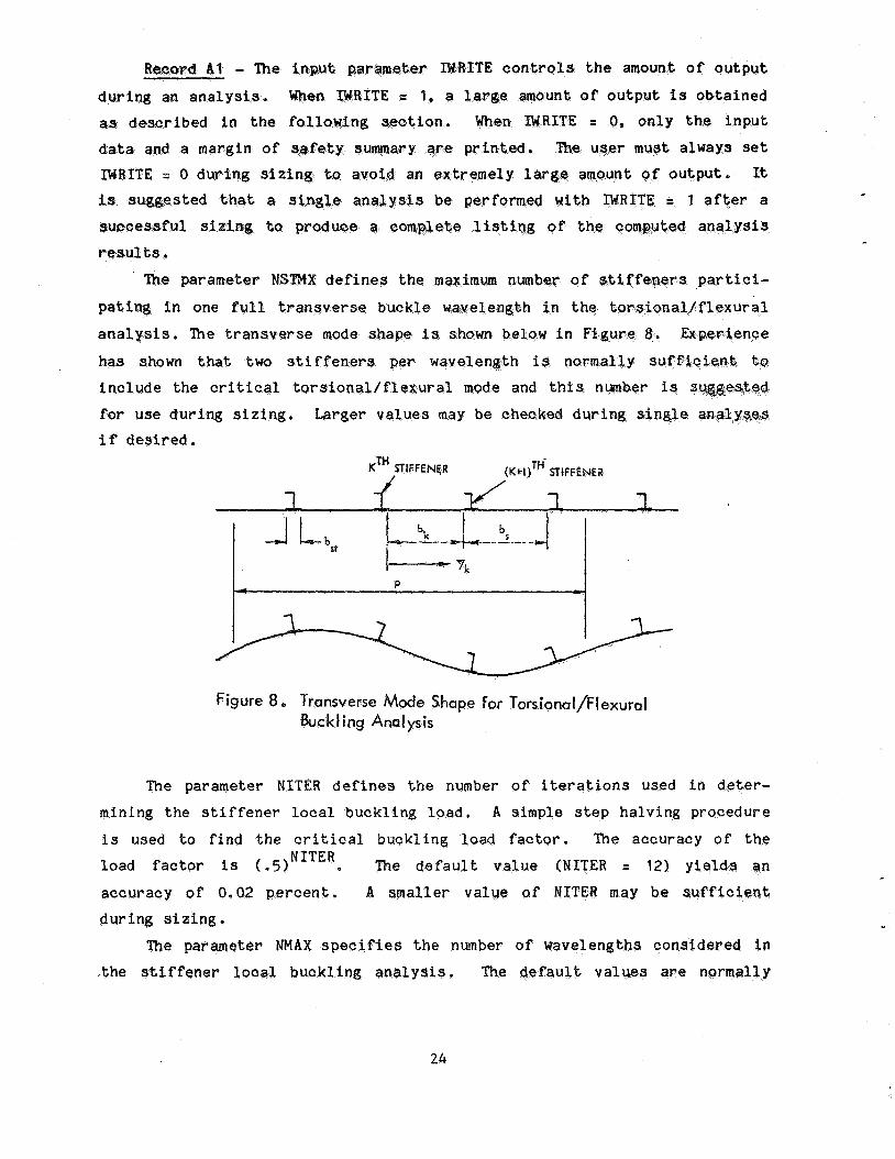
NS Max e p s per t t a n s v e p s e buck le f u l l wavelength i n a 1/ flex ur aK. e'. D e f a u l t = 2
16
NITER
WAX
m
A 2 - Geometry
Par ame t er
W(1)
W(2)
W(3)
W(4)
H
BS
XL
Number of i t e r a t i o n s t o be used i n de t e rmin ing s t i f f e n e r l o c a l b u c k l i n g load . Default = 12
Maximum number o f half-waves to be checked i n stiffener 1 oc a 1 b ue k l ing c a l c u l a t i o n s . Default z 2 XL/(skin i n i t i a l buck l ing wavelength) for
b l a d e , = 2 * XL/W(S) f o r stiffener wi th free f l a n g e .
z
D e s c r i p t i o n
Le f t free f l a n g e wid th .
Right free f l a n g e width.
Left a t t a c h e d f l a n g e wid th .
Right a t t a c h e d f l a n g e wid th .
S t i f f e n e r h e i g h t .
S t i f f e n e r spac ing .
Panel l e n g t h .
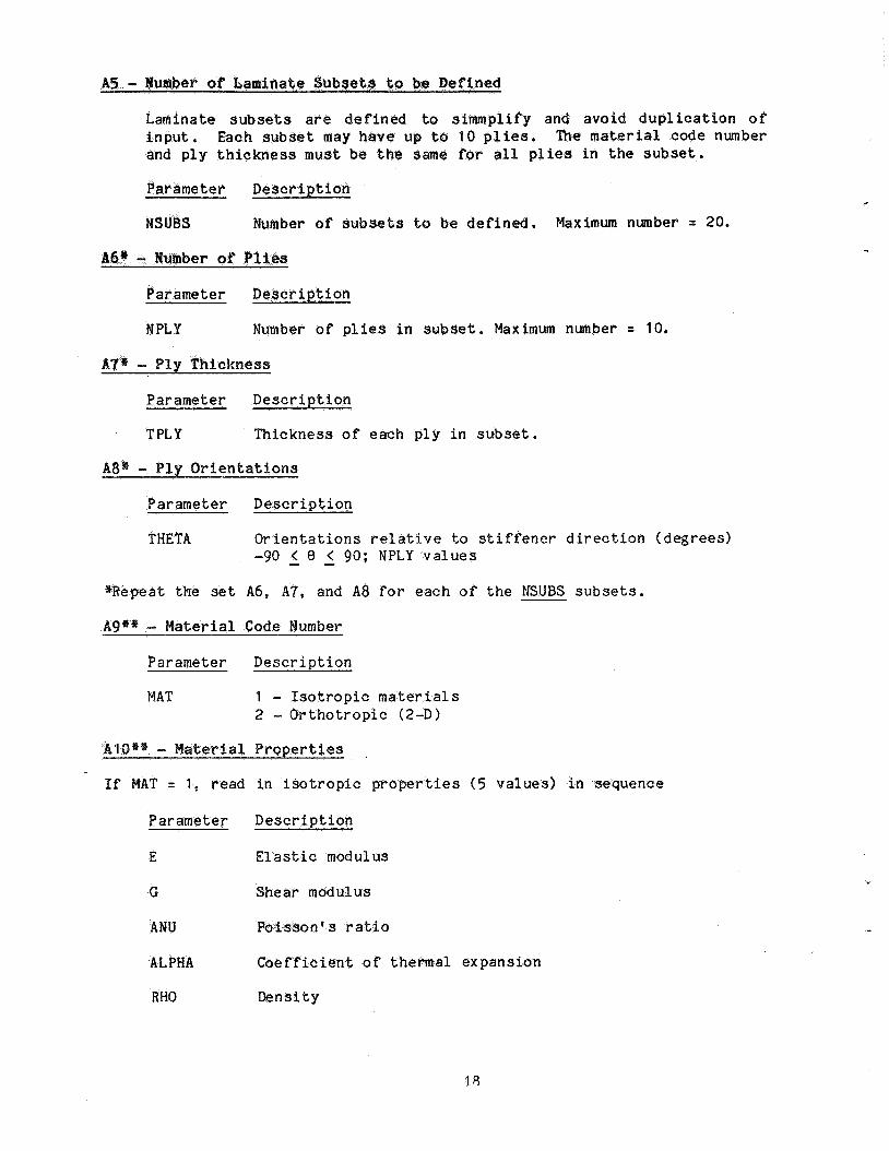
A 3 * - P l a t e E lemen t Symmetry and Repeat I n d i c a t o r
Parameter D e s c r i p t i o n
NSYM 0 - No Symmetry. 1 - Element lay-up is symmetrical wi th r e s p e c t t o middle
s u r f a c e . Only lower h a l f o f e lement is s p e c i f i e d .
NLS Number o f s u b s e t i d e n t i f i c a t i o n s t o b e read on n e x t l i n e . Maximum = 30
NREP Number o f times NLS s u b s e t s a r e t o b e r e p e a t e d .
A4* - Plate Element Subse t I d e n t i f i c a t i o n Numbers
Parameter D e s c r i p t i o n
LS NLS s u b s e t i d e n t i f i c a t i o n s s t a r t i n g a t lower surface of element . A n e g a t i v e s i g n i n f r o n t of t h e s u b s e t i d e n t i - f i c a t i o n number i n d i c a t e s t h a t p l y o r i e n t a t i o n s are t o b e read i n r e v e r s e d o r d e r .
*Repeat t h e set A3 and A4 f o r each nonzero p l a t e element i n t h e o r d e r : W(1), W(21, W(3), W(4), web, s k i n .
17
Laminate s u b s e t s are d e f i n e d to simmplify and avoid d u p l i c a t i o n of i n p u t . Each s e t may have up t o 10 p l i e s . me material code number and p l y t h i c k n must be t h e same for a l l p l i e s i n the s u b s e t .
ber of s u b s e t s be def ined . Maximum n
Par ame t e r
r of p l i e s i n s u b s e t . Maximum number = 10.
Parameter D e s c r i p t i o n
T PLY Th ickness of each p l y i n s u b s e t .
Pa rame te r D e s c r i p t i o n
THETA O r i e n t a t i o n s r e l a t i v e t o s t i f fener d i r e c t i o n ( d e g r e e s ) -90 < 8 < 90; NPLY v a l u e s - -
@Repeat the set A6, A", and A8 f o r each of t h e NSUBS subse t s .
- Material Code
Parameter D e s c r i p t i o n
MAT 1 - I s o t r o p i c mater ia l s 2 - O r t h o t r o p i c (2-D)
a t e r i a l P r o p e r t i e s ,
AT = 1 , read i n isotropic p r o p e r t i e s (5 v a l u e s ) i n sequence
P a r ame ter
E E la s t i c modulus
G Shear m
ANU o n ' s r a t i o
ALPHA f f i c i e n t of thermal e x p a n s i
RHO Dens i ty
D e s c r i p t i o n
c
b
If MAT = 2, read i n 2-D o r t h o t r o p i c p r o p e r t i e s (7 v a l u e s )
Parameter D e s c r i p t l o n
E l l E las t ic modulus ( f iber d i r e c t i o n )
E22 Elastic modulus ( t r a n s v e r s e d i r e c t i o n )
G 1 2 Shear modulus ( in-p lane)
ANU 12 Major P o i s s o n * s r a t i o
ALPHA 1 C o e f f i c i e n t of thermal expans ion ( f i b e r d i r e c t i o n )
AL PHA 2
RHO Dens i ty
A
C o e f f i c i e n t of the rma l expans ion ( t r a n s v e r s e d i r e c t i o n )
A l l * * - Material Allowables
If MAT = 1, read i n i s o t r o p i c material allowables (6 v a l u e s ; 3 s t r a i n s and 3 stresses) i n sequence ( a l l v a l u e s p o s i t i v e ) .
P ar ame t e r
€
€
T
C
Y
T U C 7
(T
If MAT = 2, read
D e s c r i p t i o n
T e n s i l e s t r a i n
Compressive s t r a i n
Shear s t r a i n
T e n s i l e stress
Compressive stress
Shear stress
i n o r t h o t r o p i c material allowables ( 1 0 v a l u e s ; 5 s t r a i n s and 5 stresses) i n sequence ( a l l v a l u e s p o s i t i v e ) .
Parameter D e s c r i p t i o n
€ T e n s i l e s t r a i n ( f i be r d i r e c t i o n )
€
4 T e n s i l e s t r a i n ( f ibe r d i r e c t i o n )
E Compressive s t r a i n ( t r a n s v e r s e d i r e c t i o n )
1T
1c
2T
26
Compressive s t r a i n ( t r a n s v e r s e d i r e c t i o n )
Y Shear s t r a i n ( in -p l ane )
19
(7 T e n s i l e stress (f iber d i r e c t i o n ) 1T Compressive stre ( t r a n s v e r s e
a" r d i r e c t i o n ) 2T
C Compressive stress ( t r a n s v e r s e c t i o n )
T Shear stress ( in-plane)
a t t he set 11 for e a c h of t h e materials.
Pa rame te r D e s c r i p t i o n
MOPT aximum s t r a i n c r i t e r i o n used for s k i n and s t i f f s t r e n g t h
2 - Tsai-Wil l c r i t e r i o n used for s k i n and s t i f f e n e r
ICLAMP 0 - Panel e n d s s imply suppor ted 1 - Panel ends clamped for c a l c u l a t i o n of moment due t o
p r e s s u r e on1 y
NOB UCK 0 - Skin is allowed t o b u c k l e 1 - S k i n is n o t a l lowed to buck le
ISEP 0 - S k i n / s t i f f e n e r i n t e r f a c e stress a n a l y s i s n o t performed' 1 - S k i n / s t i f f e n e r i n t e r f a c e stress a n a l y s i s performed
MPX Number of l o n g i t u d i n a l l o c a t i o n s p e r quar te r -wavelength a t which i n t e r f a c e sbresses a re c a l c u l a t e d . D e f a u l t = 2.
NPY Number of t r a n s v e r s e l o c a t i o n s s t a r t i n g a t t he web, across o n e a t tached f l a n g e w i d t h , W ( 3 ) or W(4), a t which i n t e r f a c e stresses are c a l c u l a t e d . D e f a u l t = 2. Maximum = 21,
SEP Number of t r a n s v e r s e shape f u n c t i o n s used i n i n t e r f a c e stress a n a l y s i s , Defaul t = IO. Maximum z 20.
- Loads and c c e n t r i c t i e s
Parameter D e s c r i p t i o n
X N ( 1 ) Axial load per u n i t width ( t e n s i o n p o s i t i v e ) .
m(2 1 Transve r se load per u n i t w id th ( t e n s i o n p o s i t i v e ) .
X N ( 3 ) Shear load per u n i t w i d t h .
PRESS Normal p r e s s u r e ( i n t e r n a l p o s i t i v e ) .
DELT Temperature change from u n s t r e s s e d s t a t e ( t e m p e r a t u r e rise p o s i t i v e ) e
7n
DEL Ratio of i n i t i a l bow t o p a n e l l e n g t h (program checks :DEL).
DELNX E c c e n t r i c i t y of a x i a l load measured p o s i t i v e from o u t e r s u r f a c e of s k i n . D e f a u l t = load a t c e n t r o i d .
A14* - Material S p e c i f i c a t i o n
Parameter D e s c r i p t i o n
MATNO Material number from t h e material list t o be used for each l a m i n a t e s u b s e t . Read NSUBS v a l u e s .
A151 - S t i f f n e s s Requirements
Parameter D e s c r i p t i o n
GTREQ Required s k i n s h e a r s t i f f n e s s p e r u n i t width.
ETREQ Required p a n e l e x t e n s i o n a l s t i f f n e s s p e r u n i t w i d t h .
A16* - Design S t r a i n L i m i t a t i o n s
I n p u t p o s i t i v e v a l u e s . Use l i m i t 3llowables with l i m i t l o a d s . Use u l t i m a t e a l l o w a b l e s with u l t i m a t e loads. Zero v a l u e s d e f a u l t t o mater ia l a l l o w a b l e s t r a i n s .
Parameter D e s c r i p t i o n
STRLIM( 1 ) F i b e r d i r e c t i o n t e s n i o n membrane s t r a i n allowable i n s k i n .
STRLIM(2) F i b e r d i r e c t i o n compression membrane s t r a i n allowable i n s k i n .
STRLIM(3) T r a n s v e r s e d i r e c t i o n t e n s i o n membrane s t r a i n allowable i n s k i n .
STRLIM(4) T r a n s v e r s e d i r e c t i o n compression membrane s t r a i n allowable i n s k i n .
*Repeat the s e t A12 t h r o u g h A16 f o r each of t h e NLOADS load cases.
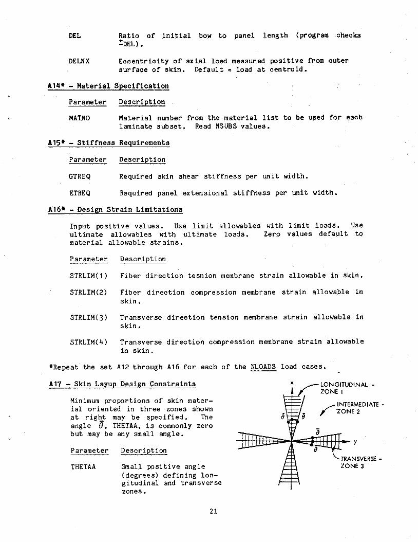
A17 - S k i n Layup Design C o n s t r a i n t s
Minimum p r o p o r t i o n s of s k i n mater- i a l o r i e n t e d i n three zones shown a t r i g h t may be s p e c i f i e d . The a n g l e e , THETAA, is commonly z e r o b u t may be any small a n g l e .
Parameter D escr i p t i o n
THETAA Small p o s i t i v e a n g l e ( d e g r e e s ) d e f i n i n g lon- g i t u d i n a l and t r a n s v e r s e zones.
21
T(1) Minim p r o p o r t i o n of s k i n m a t e r i a l r e q u i r e d to be o r i e n t - s$ between 2 THETAA from t h e l o n g i t u d i n a l d i r e c t i o n (Zone I ) .
SKRAT(2) M i p r o p o r t i o n of s k i n m a t e r i a r e q u i r e d to have t ions b e t ween l o n g i t u d i n a l d t r a n s v e r s e zones
RAT(3) Minimum pro n m a t e r i a l r e q u i r e d to be o r i e n t - THETAA from t h e t r a n s
3 ) . !
Parameter D e s c r i p t i o n
I n p u t t h e wwd E i n column 1.
The i n p u t d a t a r e q u i r e d f o r pane l s i z i n g and a n a l y s i s have been
d e f i n e d i n summary form i n t h e preceding s e c t i o n s . The i n p u t r e c o r d s t h a t
r e q u i r e f u r t h e r a t t e n t i o n a r e d i s c u s s e d below.
Record S2 - The computa t iona l c o s t o f s i z i n g a panel i s a s t r o n g
f u n c t i o n of t h e number of i n d e p e n d e n t d e s i g n v a r i a b l e s , NDV, u sed i n the
s i z i n g procedure . The o p t i m i z a t i o n procedure computes g r a d i e n t s t o t h e
c o n s t r a i n t s (marg ins o f s a f e t y ) and t h e o b j e c t i v e f u n c t i o n (we igh t ) a t t h e
s t a r t o f each o p t i m i z a t i o n i t e r a t i o n t o de te rmine how to improve t h e
d e s i g n . S i n c e these g r a d i e n t s a r e f i n i t e difference g r a d i e n t s , one com-
p l e t e a n a l y s i s is r e q u i r e d f o r each o f t h e NDV d e s i g n v a r i a b l e s a t each i t e r a t i o n . If ten i t e r a t i o n s are required to reach an optimum des ign and
NDV = 8, 80 a n a l y s e s a r e r e q u i r e d j u s t t o o b t a i n g r a d i e n t i n fo rma t ion . A d d i t i o n a l a n a l y s e s a r e r e q u i r e d i n each i t e r a t i o n c y c l e t o l o c a t e t h e
optimum f o r t h a t c y c l e . Although t h e a n a l y s i s procedures are computa- t i o n a l l y e f f i c i e n t , computa t iona l expense can be s i g n i f i c a n t i f a l a r g e
number of a n a l y s e s a r e r e q u i r e d . The re fo re , a v a r i a b l e should be d e f i n e d
a s a d e s i g n v a r i a b l e o n l y if it is c r i t i c a l t o t h e o p t i m i z a t i o n p rocess .
One or more v a r i a b l e s may be l i n k e d a t p r a c t i c a l p r o p o r t i o n s to a s i n g l e
d e s i g n var iable (see Record S8). In t h i s way a p r a c t i c a l d e s i g n is ob-
tained and N D l l remains small, If expe r i ence s u g g e s t s t o t h e user t h a t a cer ta in v a r i a b l e u l d l i k e l y r e a c h a p r a c t i c a l upper o r lower bound
22
d u r i n g o p t i m i z a t i o n , t h a t v a r i a b l e should be f i x e d a t t h e bound r a t h e r t h a n
s10: S l l :
be def ined a s a d e s i g n v a r i a b l e . Here aga in NDV w i l l be kep t small a t no
p e n a l t y to t h e s i z i n g p rocess .
F u r t h e r computa t iona l economy can be achieved by minimizing t h e number of o p t i m i z a t i o n i t e r a t i o n s r e q u i r e d t o r e a c h an optimum. Th i s can be done
by s t a r t i n g t h e s i z i n g p rocess from a r e a s o n a b l e d e s i g n . The s t a r t i n g
d e s i g n should have r e a s o n a b l e p r o p o r t i o n s and c r i t i ca l margins of s a f e t y which do n o t g r e a t l y exceed t h e i r def ined lower bounds. S i n g l e a n a l y s e s , s h o u l d be performed to o b t a i n a r e a s o n a b l e d e s i g n b e f o r e s t a r t i n g t h e
s i z i n g p r o c e s s . I f e i t h e r a g r e a t l y over des igned o r a h i g h l y i n f e a s i b l e
c r o s s - s e c t i o n is chosen a s a s t a r t i n g d e s i g n , an optimum w i l l e v e n t u a l l y be
reached bu t perhaps o n l y a f t e r a l a r g e number o f i t e r a t i o n s .
Record S3 - The i n p u t parameter IPRINT c o n t r o l s t h e amount o f o u t p u t
d u r i n g o p t i m i z a t i o n . It should normal ly b e set e q u a l t o 2 d u r i n g s i z i n g .
This w i l l g i v e t h e user u s e f u l i n fo rma t ion on i n t e r m e d i a t e d e s i g n s ob ta ined
b e f o r e t h e f i n a l d e s i g n is reached . More or less o u t p u t may be ob ta ined by
i n c r e a s i n g o r d e c r e a s i n g IPRINT. The o t h e r pa rame te r s i n t h i s and s u b s +
quent items t h a t have d e f a u l t v a l u e s should be allowed to assume t h e s e v a l u e s u n l e s s no ted .
Records S9 - S11 - The pa rame te r s i n these i n p u t r e c o r d s d e f i n e t h e
c o n s t r a i n t set o r sets. If a l l marg ins o f s a f e t y have t h e same bounds,
o n l y one c o n s t r a i n t set n e e d s t o be d e f i n e d . In t h i s c a s e NCONS = 1,
I C O N = 1, JCON = 16, KCON = 0. If, f o r example, t h e margin o f s a f e t y i n Yode 12 is r e q u i r e d t o have a lower bound of 0.1 and a l l o t h e r margins o f
s a f e t y a r e s i m p l y r e q u i r e d t o be posi t ive, three c o n s t r a i n t s e t s would be
r e q u i r e d (NCONS = 3 ) . Records S10 and S11 would be r epea ted t h r e e t i m e s as
fo l lows :
s 70: S l l :
s 10: S l l :
1 11 0 0. 1.E16
12 12 0 0.1 0.1
13 16 0 0. 1.E16
23
- The i n n u t ITE c o n t r o l s t h e amou
d u r i n g an a n a l y s i s . When WRITE = 1, a f a r as d e s c r i b e d i n t h e
must a lways set TE = 0 d u r i n g s i z i n g to a
y s i s be p e r f o WRITE = 1 a f t e r a
a n a l y s i s . ?he t r h a s shown t h a t t w o stiff
i n c l u d e t h e c r i t i ca l t a r s i o n a l / f l e x u r a l mode and
i f des i r ed .
Figure 8 e Transverse Mode Shape for Torsional/Flexural Buckling A n ~ l p i s
The parameter NITER d e f i n e s the r o f i t e r a t i o n s used i n deter-
mining t h e s t i f f e n e r l o c a l buck l ing 1 A s imple s t e p ha lv ing procedure
i s used t o f i n d t h e c r i t i c a l buckling l w d factor, The accuracy o f t h e load f a c t o r is (.5) The d e f a u l t value (NITER = 12) y i e l d s an
accu racy of 0.02 p e r o e n t . A s m a l l e r value af NITER may be ficient
d u r i n g s i z i n g
er WAX specifies t h e number of wavelengths cons ide red i o t h e st iffener local buok l ing l y s i s . The au lL v a l u e s a r e normally
24
a
s u f f i c i e n t . Should t h e s e v a l u e s n o t be l a r g e enough, a message w i l l be
r e t u r n e d (when IWRITE = 1 o n l y ) s u g g e s t i n g t h a t NMAX be i n c r e a s e d over the
d e f a u l t or t h e p r e v i o u s l y i n p u t v a l u e . Record A2 - The geometry of t h e pane l is d e f i n e d i n t h i s item. The
s t i f f e n e r h e i g h t , H, is t h e t o t a l d i s t a n c e measured from t h e i n n e r s u r f a c e
of t h e s k i n to t h e far s u r f a c e of t h e free f l a n g e a s shown i n F i g u r e 2.
The f l a n g e w i d t h s a r e measured to t h e web c e n t e r l i n e r e g a r d l e s s of whether
o n e or two f l a n g e s are p r e s e n t a t e i ther f lange/web j u n c t i o n .
Records A 3 - A 8 - The c o n f i g u r a t i o n of each of' t h e s t i f f e n e r e l emen t s and t h e s k i n a r e s p e c i f i e d i n t h e s e items i n terms of the l a m i n a t e s u b s e t s . In t h i c k l a m i n a t e s , a g iven s t a c k i n g sequence is o f t e n r e p e a t e d s e v e r a l times, e i ther d i r e c t l y or i n r eve r sed order. Laminate subse t s are d e f i n e d
i n order t o conse rve s t o r a g e and t o r educe t h e amount of i n p u t da t a
r e q u i r e d . For example, i n t h e 20-ply l a m i n a t e
t h e 5-ply s u b s e t
[+30/0,/90 - 1
o c c u r s fou r times, twice i n the s p e c i f i e d sequence and twice i n r e v e r s e d
sequence .
Up to 2 0 d i s t i n c t l a m i n a t e s u b s e t s (NSUBS) may be d e f i n e d . Each
s u b s e t may have a maximum of 10 p l i e s o r l a y e r s , which must a l l have t h e same t h i c k n e s s and basic m a t e r i a l p r o p e r t i e s . S u b s e t s a r e to be d e f i n e d
s e q u e n t i a l l y 1, 2, ..., L, ..., NSUBS by s p e c i f y i n g t h e number of p l i e s ,
NPLY, t h e p l y t h i c k n e s s , TPLY, and t h e o r i e n t a t i o n s , THETA, of each p l y i n
t h e s u b s e t .
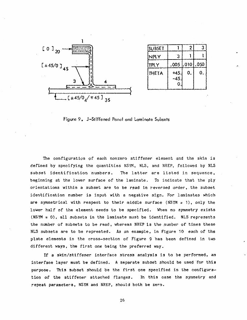
To i l l u s t r a t e t h e concep t of l a m i n a t e s u b s e t s , c o n s i d e r t h e J - s t i f f e n -
ed pane l shown i n F i g u r e 9. The a v a i l a b l e p l y t h i c k n e s s i s assumed t o b e
0.005 i n . Three s u b s e t s a r e d e f i n e d . The first s u b s e t c o n s i s t s of 3 p l i e s
having o r i e n t a t i o n s o f +45', -45'. and 0'. The second s u b s e t h a s two p l i e s a t 0' and is t r e a t e d a s one l a y e r w i t h a t h i c k n e s s of 0.01 i n . The t h i r d
subse t combines 10 p l i e s i n t o one l a y e r w i th t h i c k n e s s of 0.05 i n . and a n
o r i e n t a t i o n of 0'.
25
1
I t
4
Figure 9. J-Stiffened Panel and Laminate Subsets
The c o n f i g u r a t i o n o f each nonzero s t i f fener element and t h e s k i n i s
d e f i n e d by s p e c i f y i n g t h e q u a n t i t i e s NSYM, NLS, and NREP, fol lowed by NLS
subse t i d e n t i f i c a t i o n numbers . The l a t t e r a r e l i s t e d i n s e q u e n c e ,
beginning a t t he lower s u r f a c e o f t h e l amina te . To i n d i c a t e t h a t t h e p l y
o r i e n t a t i o n s w i t h i n a subset are to be read i n reversed o r d e r , t h e s u b s e t
i d e n t i f i c a t i o n number is i n p u t with a n e g a t i v e s i g n . For l a m i n a t e s which
a r e symmetrical wi th r e s p e c t t o t h e i r middle s u r f a c e (NSYM = 1) . o n l y t h e
lower h a l f of t h e e l emen t needs t o be s p e c i f i e d . When no symmetry ex i s t s (NSYM = 01, a l l subsets i n the l a m i n a t e must be i d e n t i f i e d . NLS r e p r e s e n t s
t he number o f subsets t o be r e a d , whereas NREP i s t h e number o f times t h e s e NLS subsets are to be r e p r e a t e d . As an example, i n F igu re 10 each of t h e
p l a t e e l emen t s i n t h e c ros s - sec t ion of F igu re 9 h a s been de f ined i n two
d i f f e r e n t ways, t h e f irst one be ing the p r e f e r r e d way.
If a s k i n l s t i f f e n e r i n t e r f a c e stress a n a l y s i s is t o b e performed, an i n t e r f a c e l a y e r mus t be d e f i n e d . A s e p a r a t e subset should be used f o r t h i s
purpose. This s u b s e t should be t h e f i r s t one s p e c i f i e d i n t h e conf igu ra -
t ion of t h e s t i f f e n e r a t t a c h e d f l a n g e s . In t h i s c a s e t h e symmetry and
r e p e a t pa rame te r s , NSYH and NREP, should bo th be ze ro .
26
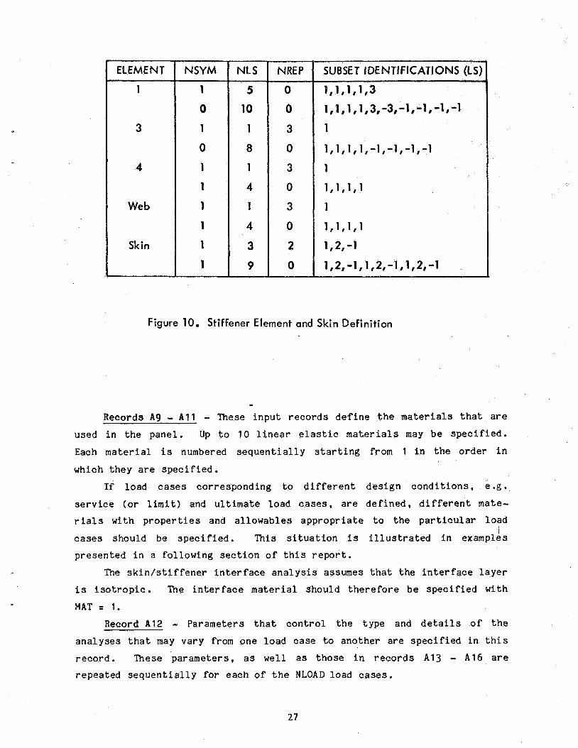
Figure 10. Stiffener Element and Skin Definition
- Records A 9 - All - These i n p u t r e c o r d s d e f i n e t h e m a t e r i a l s t h a t are
used i n t h e pane l . Up t o 10 l i n e a r e l a s t i c m a t e r i a l s may be s p e c i f i e d .
Each m a t e r i a l i s numbered s e q u e n t i a l l y s t a r t i n g from 1 i n t h e o r d e r i n which t h e y are s p e c i f i e d .
If load cases co r re spond ing to d i f f e r e n t d e s i g n c o n d i t i o n s , e .g.
service ( o r l i m i t ) and ul t imate load c a s e s , a r e d e f i n e d , d i f f e r e n t mate- r i a l s wi th p r o p e r t i e s and a l l o w a b l e s a p p r o p r i a t e t o t h e p a r t i c u l a r load
c a s e s should be specified. This s i t u a t i o n is i l l u s t r a t e d i n examples i
p r e sen ted i n a fo l lowing s e c t i o n o f t h i s r e p o r t .
The s k i n / s t i f f e n e r i n t e r f a c e a n a l y s i s assumes t h a t t h e i n t e r f a c e l a y e r
i s i s o t r o p i c . The i n t e r f a c e m a t e r i a l should therefore b e s p e c i f i e d wi th
MAT = 1.
Record A 1 2 - Parameters t h a t c o n t r o l t h e type and d e t a i l s o f t h e
a n a l y s e s t h a t may va ry from one load c a s e to ano the r a r e s p e c i f i e d i n t h i s
r eco rd . These pa rame te r s , a s well a s those i n records A13 - A16 a r e r epea ted s e q u e n t i a l l y f o r each of t h e NLOAD load c a s e s .
27
i n t h e stiffener and s k i n
c k l e d s k i n a n a l y s i s
for i n t h e beam-
interface stress
a p p l i e d . It is sugges t ed t h a t t h i s a n a l g s t s p o t b e perfar
in te r face stress s t a t $ 1s e v a l u a t e d . If t h e s k i n i s ed , NPX i s $hp
number of p o i n t s i n one h a l f t h e s k i n buck l ing half-wavelength. If t h e
s k i n i s n o t buckled b u t i n t e r n a l p r e s s u r e is p r e s e n t . NPX i s t h e r o f
p o i n t s i n h a l f of t h e pane l l e n g t h . If b o t h buck l ing and i n t e r n a l p r e s s u r e are p r e s e n t , NPX i s d e f i n e d r e l a t i v e t o the buck l ing wavelength
b u t stresses are computed by s u r p o s i n g t h e an t i symmet r i c and symmetric
i n t e r f a c e stresses a t a l l p o i n t s from t h e p a n e l end up t o one h a l f o f t h e
p a n e l l e n g t h . It is sugges t ed t h q t NPX be se t e q u a l t o 2. NPY is t h e
number of p o i n t s from t h e s t i f f e n e r web c e n t e r - l i n e t o t h e edge o f t h e
f lqnge . NSEP is the number of shape f u n c t i o n s used i n the i n t e r f a c e stress q n a l y g i s and should b e i n v e s t i g a t e d wi th r e s p e c t t o convergence of t h e
s o l u t i o n s for s p e c i f i c c a s e s e
- Here t h e a p p l i e d 1 s and eccent r ic i t ies a r e s p e c i f i e d .
g n i t u d e s of t h e d s q u s t meet the r equ i r emen t s d i s c u s s e d
i n qn e q r l i e r If an i n i t i a l bow ecq r i c i t y i s s p e c i f i e d , b
of bow are checked. However, t h
y f o r a p o s i b i v e bsw since t h i s
increased corn s t r a i n i n t h e s k i n . The ax
c
DELNX, should be specified o n l y i f t h e pane l a x i a l load is a p p l i e d a t a
pane l r u n o u t a t which t h e c e n t r o i d d o e s n o t a l i g n wi th the panel c e n t r o i d .
Record A14 - The m a t e r i a l associated w i t h e a c h s u b s e t is de f ined i n t h i s record. MATNO is a list of NSUBS material numbers wi th v a l u e s from 1
to MAT. For example, i f f i v e s u b s e t s e x c e p t s u b s e t 4 were made of t h e
f irst m a t e r i a l def ined and s u b s e t 4 was made of t h e second material d e f i n e d .
Record A16 - The d e s i g n s t r a i n l i m i t a t i o n s d e f i n e d i n t h i s record a p p l y to t h e membrane s t r a i n s i n each p l y i n t h e s k i n only . T h i s i s t h e
l a s t r eco rd t h a t is r e p e a t e d for each o f t he NLOAD load cases.
Record A17 - Lower bounds may be p laced on the p r o p o r t i o n s of s k i n
m a t e r i a l o r i e n t e d i n t h r e e g e n e r a l d i r e c t i o n s o r zones a s shown i n t h e
d e f i n i t i o n of record A 1 7 . In t h i s way t h e s k i n l a m i n a t e may be r e q u i r e d t o have specific r e l a t i v e s t i f f n e s s character is t ics . For example, if a s k i n t h a t is f l e x i b l e , or n so f t tq , i n t h e l o n g i t u d i n a l d i r e c t i o n is desired, h i g h
lower bounds on t h e r e l a t i v e amount of material i n t h e t r a n s v e r s e and/or
i n t e r m e d i a t e d i r e c t i o n s may be s p e c i f i e d . In t h i s c a s e t h e lower bound on
m a t e r i a l i n t h e l o n g i t u d i n a l d i r e c t i o n s would be set to zero .
I f o n l y 0, - +45, and 90-degree o r i e n t a t i o n s a r e t o be used , t h e a n g l e
T H E T A A , d e f i n i n g t h e e x t e n t of t h e l o n g i t u d i n a l and t r a n s v e r s e zones , may be set to z e r o deg rees . If - +5, - +45, - +85-degree o r i e n t a t i o n s a r e t o be
u s e d , T H E T A A shou ld be set to 5 d e g r e e s .
OUTPUT
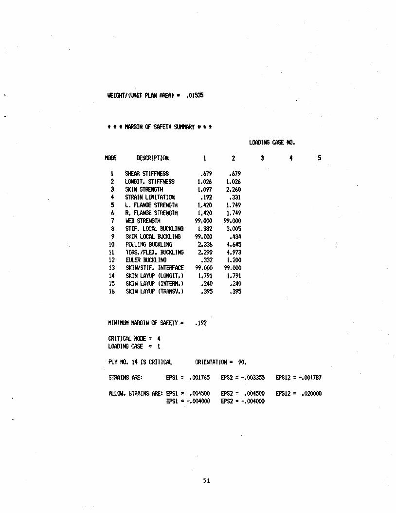
I n t he a n a l y s i s mode, t h e o u t p u t is produced by t h e r o u t i n e s i n
A N A L I Z . With W R I T E = 0, minimum o u t p u t is r e t u r n e d from t h e s e r o u t i n e s .
This i n c l u d e s t h e i n p u t d a t a , t he panel we igh t , a summary of t h e margins
o f s a f e t y f o r a l l l oad c a s e s , and t h e c r i t i c a l margin of s a f e t y , t h e
f a i l u r e mode, and the a s s o c i a t e d load c a s e . ‘&en P d R I T E = 7 , t h e i n p u t d a t a i s r e t u r n e d fo l lowed by d e t a i l e d
results from each a n a l y s i s r o u t i n e for each load case and for b o t h p o s i t i v e
and n e g a t i v e v a l u e s of i n i t i a l bow e c c e n t r i c i t y .
29
p r o p e r t i e s of t h e s t i f f e n e r o n l y , w i t h no a t t a c h e d s k i n , a r e er s u r f a c e of t h e s k i n to
n and unbuckled pane l
es a r e p r i n s k i n pa rame te r s and
membrane stiff s t i f f n e s s and
c o r n e r s of? a q u a d r a n t of
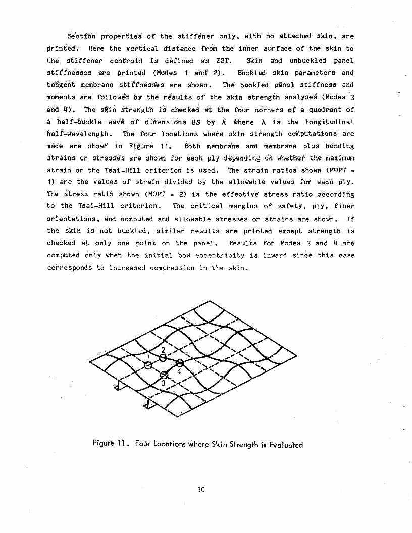
re s k i n s t r e n
t o t h e Tsai-Hi11 c r i t e r i o n . The c r i t i c a l margins of s a f e t y , p l y , f iber
o r i e n t a t i o n s , and computed and a l l o w a b l e stresses or s t r a i n s are shoctn. t h e s k i n is n o t b u c k l e d , s i m i l a r r e s u l t s a r e p r i n t e d excep t s t r e n g t h i s
checked d t o n l y one p o i n t on t h e pane l . R e s u l t s f o r Modes 3 and 4 a r e
computed o n l y when the i n i t i a l bow e c c e n t r i c i t y i s inward s i n c e t h i s e a s e
co r re sponds t o i n c r e a s e d compression i n the s k i n .
Figure 1 1 Four Locations where Skin Strength i s Evaluated
30
S i m i l a r r e s u l t s a r e p r i n t e d for t h e s t i f f e n e r s t r e n g t h modes. If t h e
s t i f f e n e r h a s free f l a n g e s , o n l y Modes 5 and/or 6 are checked. If t h e
s t i f f e n e r is a b l a d e , o n l y Mode 7 is checked. Summary r e s u l t s follow for t h e b u c k l i n g a n a l y s e s , Modes 8 through 12. A l l of t h e s e a n a l y s e s are performed for boCh inward and outward i n i t i a l bow e c c e n t r i c i t i e s . !
The s k i d s t i f f e n e r i n t e r f a c e stress a n a l y s i s (Mode 13) is performed o n l y for inward bow e c c e n t r i c i t y s i n c e t h i s c o r r e s p o n d s t o a h ighe r d e g r e e
of s k i n pos tbuck l ing . T o t a l stresses a t p o i n t s spaced e q u a l l y i n t h e x d i r e c t i o n and i n t h e y d i r e c t i o n are shown. If t h e s k i n is buckled , NPX
p o i n t s a r e spaced l o n g i t u d i n a l l y a d i s t a n c e X/(2*NPX) a p a r t s t a r t i n g a t t h e panel end. If i n t e r n a l p r e s s u r e is p r e s e n t and t h e s k i n is post-
buck led , t h e same s p a c i n g i s ma in ta ined b u t t h e number of p o i n t s i s i n c r e a s e d so t h a t stresses are checked from t h e panel end to midspan. If
i n t e r n a l p r e s s u r e is p r e s e n t b u t t h e s k i n is n o t buckled , NPX p o i n t s are spaced XL/(2*NPX) a p a r t from t h e pane l end to midspan. If t h e s k i n i s not buckled and zero or e x t e r n a l p r e s s u r e is p r e s e n t , no s k i n / s t i f f e n e r i n t e r - f a c e stress a n a l y s i s i s performed. In a l l c a s e s , NPY p o i n t s e q u a l l y spaced
a c r o s s one a t t a c h e d f l a n g e wid th a r e d e f i n e d s t a r t i n g a t t h e s t i f f e n e r web
c e n t e r l i n e . The margin o f s a f e t y and t h e c r i t i c a l l o c a t i o n a r e p r i n t e d
a long wi th t h e pos tbuck l ing and p r e s s u r e edge moments and s h e a r s i n t h e
s k i n a t t h e edge of t h e a t t a c h e d f l a n g e .
Skin l a y u p d e s i g n r e q u i r e m e n t s (Modes 14-16) and a c t u a l v a l u e s of t h e
p o r t i o n s of t h e s k i n m a t e r i a l o r i e n t e d i n t h e t h r e e zones p r e v i o u s l y de-
f i n e d a r e p r i n t e d . The panel weight and margin of s a f e t y summary conc lude t h e a n a l y s i s o u t p u t .
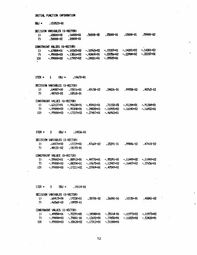
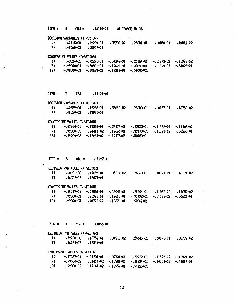
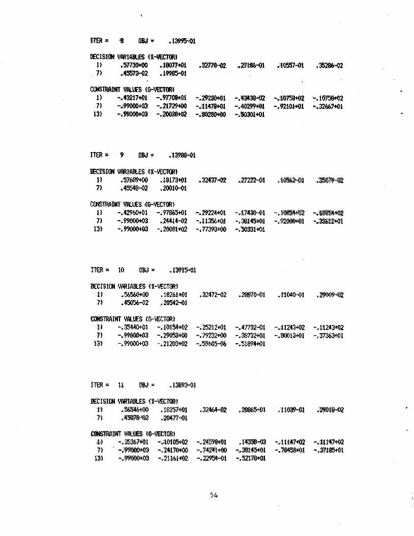
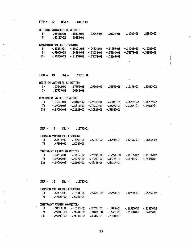
In t h e s i z i n g mode, s i z i n g i n p u t and d e f a u l t d a t a is p r i n t e d i f
IPNPUT = 1. T h i s i s fo l lowed by t h e a n a l y s i s d a t a for t h e s t a r t i n g d e s i g n .
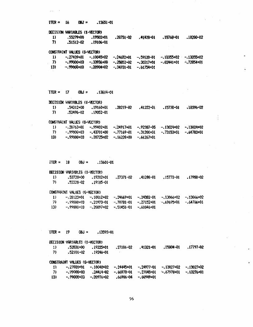
If IPRINT = 2, a s s u g g e s t e d , t h e o b j e c t i v e f u n c t i o n v a l u e , t h e d e s i g n
v a r i a b l e s , and t h e c o n s t r a i n t v a l u e s w i l l be p r i n t e d for t h e i n i t i a l
d e s i g n , t h e i n t e r m e d i a t e d e s i g n s and t h e f i n a l d e s i g n . The c o n s t r a i n t
v a l u e s a r e r e l a t e d t o t h e margins of s a f e t y i n each mode for t h e c r i t i c a l
l oad case for each mode, This r e l a t i o n is
G = - MS/SCALE
where G i s t h e c o n s t r a i n t v a l u e , MS i s t h e margin of s a f e t y and SCALE i s a
s c a l e f a c t o r . The s c a l e f a c t o r i s t h e s m a l l e r of 0.1 and t h e a b s o l u t e
31
Val& of the lower r a i n t . When a parCicula3r; mode does
y td a c e r t a i n
After convergence t o an optimum is iarbles and co t. The margin of
safety summary for
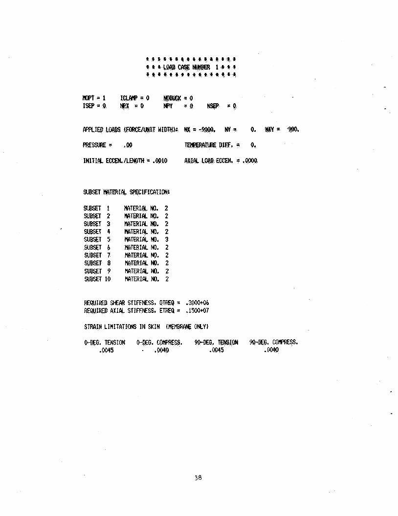
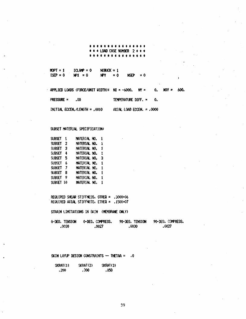
l o a d s o f 6000 l b s / i n l o n
i n i t i a l bow e c c e n t r i c i t y pane l must be buck l ing r e s i s t a n t a t t h e l i m i t l o a d s b u t
t h e pos tbuck l ing range at u l t i m l o a d s equal t o 1.5 t l o a d s .
For p r a c t i c a l reahsons , t h e s t i f f e n e r i s s a t a t 6 i
t h e attac 'hed f l a n g e w i d t h s ar"e set a t 0.75 inch each. The panel
f i x e d a t 20 inches. . The panel weight should b e minimized. Crt s t o n s , m 'a t e r i a l p r o p e r t i e s , m a t e r i a l a l l o le's and o t h e r d
s a r e shown i n t h e o u t p u t . The s t i f f e n e r i s bonded t o t h e skin. A s k i n / s t i f f e n e r i n t e r f a c e
stress a n a l y s t s is performed i n t h e f i n a l a n a l y s i s (Example 4).
I
32
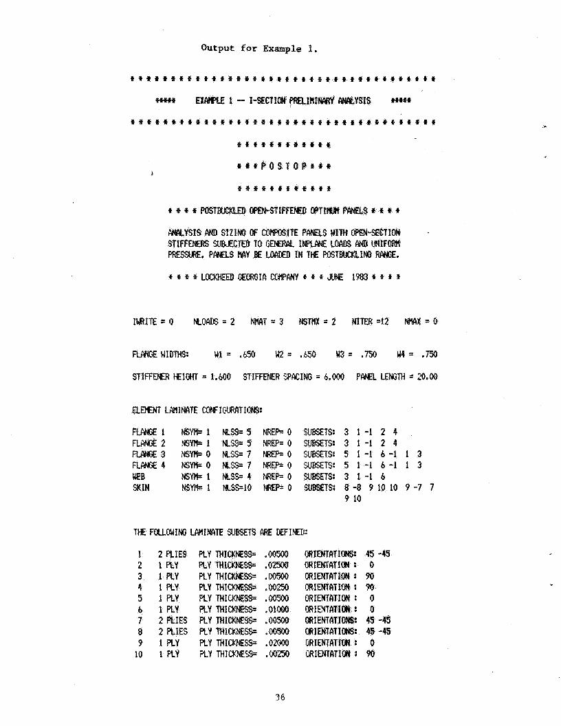
EXAMPLE 1 - P R E L I M I N A R Y A N A L Y S I S
h
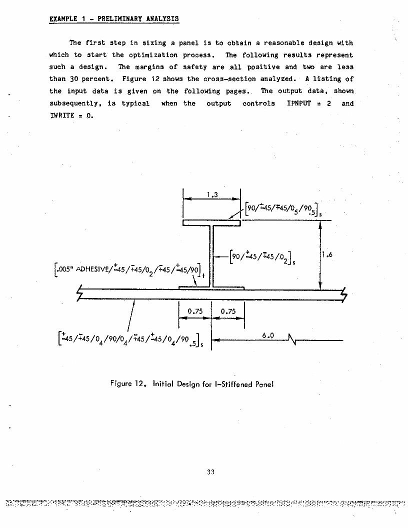
The first s t e p i n s i z i n g a panel is t o o b t a i n a r e a s o n a b l e d e s i g n with
which to s t a r t t h e o p t i m i z a t i o n process. The fo l lowing results r e p r e s e n t
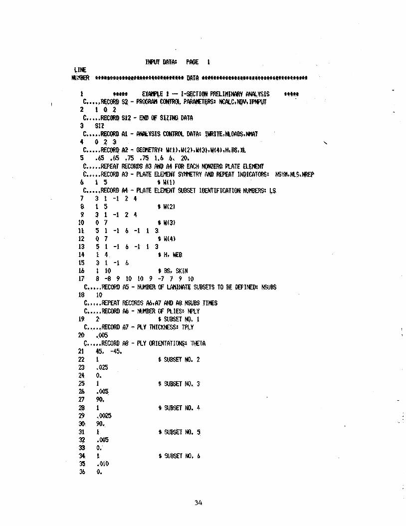
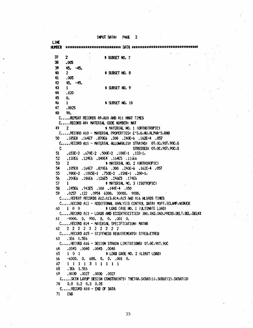
such a des ign . The margins of safety are a l l p o s i t i v e and two are less t h a n 30 percen t . F igu re 12 shows the c ross - sec t ion ana lyzed . A l i s t i n g of t h e i n p u t data is given on the fo l lowing pages. The o u t p u t da ta , shown
subsequen t ly , is t y p i c a l when the o u t p u t c o n t r o l s IPNPUT = 2 and
IWRITE = 0.
Figure 12, Init ial Design for I-Stiffened Panel
33
WwB I
1
7 3 1 - 1 2 4 8 1 5 $ W(21 a 3 1 - 1 2 4
10 0 7 d w131 11 5 1 - 1 4 - 1 1 3 12 0 7 W(4) 13 5 1 - l b - 1 1 3 14 k 4 15 3 1 -1 6
17 8 -8 9 10 10 9 -7 7 9 10 1,6 1 1.9 9 B% SKIN
c.....REm A6 -
22 1 23 .OB
0. 1 . 3
28 n
1 No* 5
3 r E 1 9m No. b 3 ,910 36 0.
..
34
3 7 2 SSUBSETM, 7 38 m o o 5 39 45. 4. 4 0 2 SSUBSETNo.8 41 ,005 42 45, -45. 43 1 IsuBsnNo.9 44 ,020 4s 0. 4 6 1 s SUBSR Ho. 10 47 ,0025 98 90.
C.....REPEAT RECORDS MtMO AND A11 N M T T I E S C.. e .RECORD A9: MTERICY CODE MJHE€R: MT
49 2 % MTERIAL No. 1 ((3RMoTRopIC)
50 .185E8 .164€7 ,87066 .300 .24OE-6 .162E-4 ,057 C. a .RECORD A10 - WTERIIV PROPERTIES: E'SIG,M,CILPHCI'S,RHO
C.....REOXD A11 - EVITERIIY. AUMBLES~ STRAINS: c
OT,oc19OT*9OC*S STRESSES: OT, O C s 90Tv 9OC. S
51 .653E-2 ,570E-2 ,500E-2 ,100E-1 ,133-1, 52 .13?€6 ,124Eb .840€4 .164ES ,1133 5 3 2 s MTERIAL Ho. 2 (ORTHORDPIC) 54 .1=8 .164€7 .870Eb ,300 .2W-6 .ME-4 .057 55 ,980E-2 .1005E-1 . m - 2 .1%-1 .LWl,
56 .2ooE6 .la6 ,1243 .246E5 .174€6 S I 1 % HCITERIPIL Ho. 3 (ISDTROPIC) 58 .245E6 ,94225 . am ,144E-4 ,050 59 ,0257 .122 ,0954 6300. 30000. 9ooo.
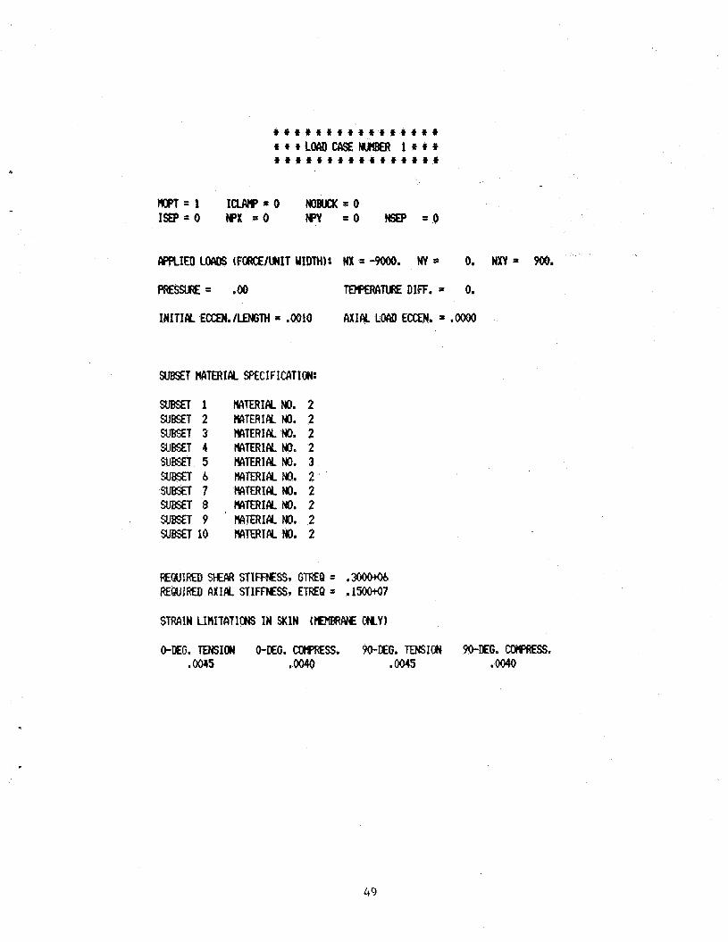
C.....MKAT RECORDS A12,A13,414,A15 /N A16 NOCIDS T I E S C. I ,fiECORD A12 - PQDITIONCY ANALYSIS OlNTRX MTA: HIPTI IWWPINOE#CK
60 1 0 0 $ L(3AD CASE Ho. 1 (UTIMTE LMD)
61 -9000. 0. 900. 0. 0. ,001 0.
b2 2 2 2 2 3 2 2 2 2 2
b3 . J 6 1.5Eb
64 ,0045 .oO40 .m5 .oO40 65 1 0 1 % LOA0 UISE No. 2 (LIHIT L W ) 66 -5000. 0. 600. 0. 0. ,001 0. 67 1 1 1 1 3 1 1 1 1 1 6% .X6 1.5E6 59 .@'I30 .GQ27 .OON ,0027
70 0.0 0.2 0.3 0.05
71 €MI
C.....RECORD A13 - LOADS AND E(XXNTR1CITIES: XNl,XN2*XN3,PRESS,KLT,~iDELNX
C.. . . .RECORD A14 - WTERJFY SPECIFICATLON: MTNO
c., . ..RECORD ai5 - STIFFNESS REQUIREENTS: GTREQ~ETKQ
C. .... MC;rXUl A16 - DESIGN STRAIN LIHITATIOHS: OT,OC~9OT,9OC
C. . e SKIN LAW DESIGN CMTR&INTS: THETAA, SXRAT ( 1 1, SKf?AT( 2) %RAT4 3)
C.....RE(XRD A18 - END W DATA
35
EX 1 - I-
f t t i # i # t t t t t t t t t t t t t C t t * f t t t t f t * t t 4 t * t f t
t t ~ f t t t t * t t t
t t t a a w a p r t t
t * + t t E t t t t t t
ST1FFEE.R HElGKl = 1,5000 STIFFENER YACING = 6.000 PPNEL LENGTH = 3.00
1 NSw1 NpssE5 NREP=o SuEsSns: 3 1 - 1 2 4 nw2 MsylTr! KSS=S NREp=o WEfrS: 3 1 - 1 2 4
3 ,*wo KSS=7 0 : 5 1 - 1 6 - 1 1 3 4 M W O M s = 7 0 5 1 - 1 6 - 1 1 3
NEB 0 : 3 1 - 1 6 %lN 0 SJJEETS: 8 -8 9 10 10 9 -7 7
9 10
1 2 RIE9 2 1 RY 3 1 RY 4 1 PLY
9 1 PLY 10 1 P t Y
P L Y THI .Or)m Y THI . om Y THI
PLY THI KY THI PLY THI RY m1 PLY MI PLY MI XY T H I W S -
45 -45 0 90 90 0 0
43 -49 45 -43 0 90
36
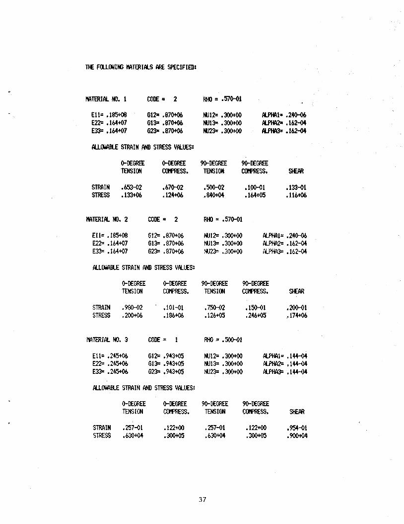
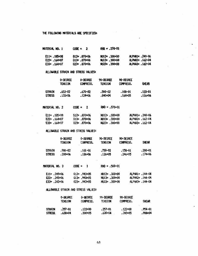
THE FoulwlItG WATERIIYS ClRE SPECIFIED:
MTERIALNo. 1 coH= 2 RHO= .sIO-ol
Ell= . 1 M GlZt . 8 7 M MJlB .3o090 m 1 = .240-06 E D .1M97 G13. . 8 7 M w13= .m &PH@ .162-04 E33= .164+07 Ms. o 8 7 W Nu23e: .3o090 AwIcL3. .16244
STRAIN .6S3-02 .670-02 ,500-02 .1oM)1 * 13-01 STRESS .133tO6 .124+06 .840+04 . lM* .116+Ob
ALLOWPBLE STRAIN fy(D STRESS VALUES:
STRAIN .980-02 . .101-01 ,750-02 ,150-01 e m 1 STRESS .Mo+ob .la* .126+05 .2&* ,17446
EICITERICY. No. 3 CODE= 1 wO=.50M)l
Ell= ,24306 Gl% .943+05 w12= .3o0+(10 wwcI1= ,144-04 En= .245+06 Gl3= ,943t05 w13= .m cypHcIz= ,144-04 E D ,24596 G 2 3 .943+05 Nu23 .3o090 w m ,144-0)
AUOWBLE STRCIIN AND STRESS VALUES:
STRAIN ,257-01 ,122m ,251-01 .mal .954-01 STRESS .W .340+05 .630+011 .3oo+o5 .9oo+o4
37
= O
3a
t t t t + t t t * t i + t + * *
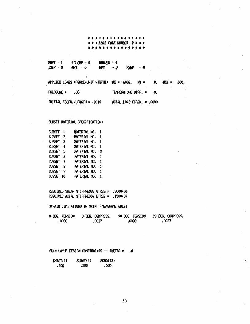
S t t + t t f t t * + * t t t t tttLOADCASENUIBER 2 t i r
m = 1 I W = O NoBllLx=l ISP-0 WX = o WY = o KSEP = o
f
r n M = .oo TMPEAIITURE DIFF. = 0.
INITIN ECCEN./tENGTH = .OOlO AXIRL LW Em. = .m
SUBSET MTERIRL PECIFI#lION:
St iBsETl SUBSET 2 SUBSET 3 SUBSET4 SUBSET5 SIBSET 6 SUBSET7 SUBSET 8 s u B s n 9 SUBxl 10
IiArnIALHO. 1 MERIALNO. 1 MERIM NO. 1 MrnIAL No. 1 HATERIAL NO. 3 ryITERIcy No. 1 HATERIAL HD. 1 MrnIALNO. 1 MTERIAL NO. 1 MrnICy No. 1
STRAIN LIHITATIONS IN SKIN 01MBRcwE MY)
0-DEG. TENSION 0-EG. COlf'fES. 90-DEG. TENSION 9O-DEG. CCWKSS. ,0030 .00n ,0030 ,0027
SKIN LAW DESIGN coNsTRc\INTS - TKTM = .O
39
1 2 3
s 6 V
9 IO 11 12 13 14 15 16
a
. 1,026 1.097 ,192
1.420 1.420 99,
1. 99, 2.336 0.
93. 1 a 791
,240 ,395
?9,oOo 3.005
.434 4.645 4. 1. 99.
1.
,395
HXNI IN OF SMTY = ,192
‘1 1 2 1 3 1
4b
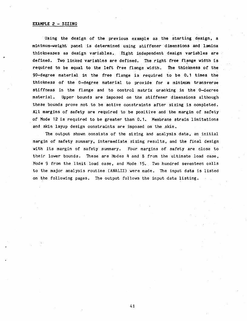
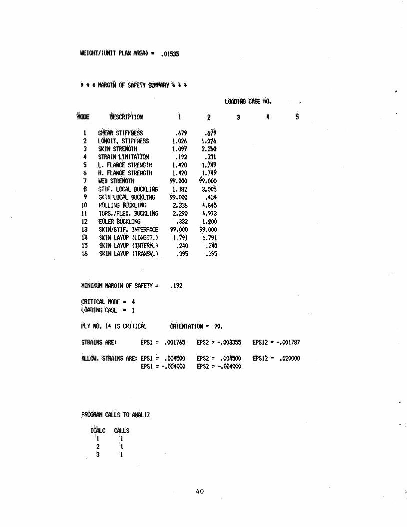
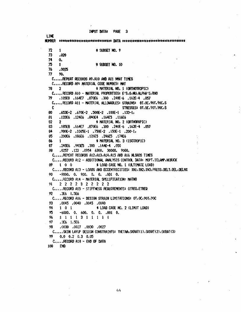
EXAMPLE 2 - SIZING Using t h e d e s i g n of t h e p rev ious example a s the s t a r t i n g d e s i g n , a
minimum-weight panel is deternl ined u s i n g s t i f f e n e r d imens ions and lamina
t h i c k n e s s e s as d e s i g n v a r i a b l e s . E i g h t independent d e s i g n v a r i a b l e s a re de f ined . Two l i n k e d v a r i a b l e s a r e d e f i n e d . The r i g h t free f l a n g e width is r e q u i r e d to b e equa l to t h e l e f t free f l a n g e w i d t h . Ihe t h i c k n e s s of t h e
90-degree material i n t he free f l a n g e is r e q u i r e d t o be 0.1 times t h e
t h i c k n e s s of t h e 0-degree material to p rov ide f o r a m i n i m u m t r a n s v e r s e
s t i f f n e s s i n t h e f l a n g e and to control ma t r ix c r a c k i n g i n t h e 0-degree material. Upper bounds are imposed on t h e s t i f f e n e r d imens ions a l though
t h e s e bounds prove n o t t o be act ive c o n s t r a i n t s a f t e r s i z i n g is completed. All margins of s a f e t y are r e q u i r e d t o be p o s i t i v e and t h e margin of s a f e t y
of Mode 12 is r e q u i r e d t o be g r e a t e r t h a n 0.1. Membrane s t r a i n l i m i t a t i o n s and sk in l ayup d e s i g n c o n s t r a i n t s a r e imposed on t h e s k i n .
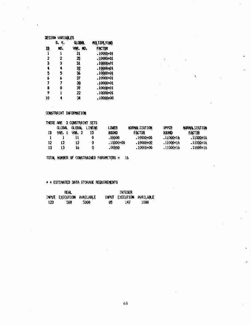
The o u t p u t shown c o n s i s t s o f t h e s i z i n g and a n a l y s i s d a t a , an i n i t i a l
margin of s a f e t y summary, i n t e r m e d i a t e s i z i n g results, and t h e f i n a l des ign
wi th i ts margin of s a f e t y summary. Four margins o f s a f e t y a r e c l o s e t o t h e i r lower bounds. These are Hodes 4 and 8 from t h e u l t imate load c a s e ,
Mode 9 from t h e l i m i t load c a s e , and Mode 15. Two hundred seventeen c a l l s t o t h e major a n a l y s i s r o u t i n e ( A N A L I Z ) were made. The i n p u t d a t a is l i s t e d
on t h e fo l lowing pages. The o u t p u t follows t h e i n p u t d a t a l i s t i n g .
41
-1. REcowl s7 w T I E S
c.....REm s7 - ESIGN 7 0. 1.0 8 0 . 2.0 % H 9 0. 1.
16 0. 1. 11 0. 1.E16 12 0. 1.Et6 1'5 0. 1 . W 14 0. 1.El6 II TPtY(9)
C..,..RECoW) S8 - ESIM VMk& 1s 1 21 % W(1) 16 2 25 $ H 17 3 31 fa 4 32 t9 5 3 20 b 37 21 7 38 22 839 23 1 2 2 21 4 34 .1
a 3
C m t 8 e .REPEAT MCDRD s8 NWTOT T I S S
c.....REm s9 -
42
L I E m
' 3 3 C.
34. C. C.
6. 35
0 2 3
-65 .65 .l5 .l5 1.6 6. M. .... Ern CIZ - GEOCRRY: W(l)IW(2)1W(3)~W(4)IH,BSIXL
a s .REPEAT REcowls A3 RND 44 FOR E M NONZERO PLATE aMEHT ....RECORD A3 - RATE QEENT SrmETRY RND REPECIT INDICATORS:
. . .RECORD R4 - PLILTE aDEKc SUBSET IDeCTIFICATION lWt@ERS: LS
NsmiNSiNREP 1 5 % W(1)
36 3 1 - 1 2 4 37 1 5 % W(2) 38 3 1 - 1 2 4 39 0 7 % W(3) 40 5 1 - 1 6 - 1 1 3 41 0 7 % ut41 42 5 1 - 1 6 - 1 1 3 43 1 4 % Hv WEB 44 3 1 - 1 6 45 1 10 % B S v SKIN 46 8 -8 9 10 10 9 -7 7 9 10
47 10 C.....REMul c15 - MplBER W LWINATE SUBSETS TO BE DEFIND: NSUBS
C.....EP€AT RECMS W347 PiND R8 WBS T I S S C.....REcoRD A6 - IulBER cb: PLIES: NPLY
4 3 2 %sllBsETNo. 1 c.. . . .RECORD A7 - PLY THICKNESS: TPLY
49 ,005 C.....REcoRD 48 - PLY ORIENTATIOIIS: THETCI
50 45. -45. 51 1 %suBsETNo.2 52 ,025 53 0. 5 4 1 csu8sETHo.3 55 ,005 56 90. 5 7 1 %sllBsETNo.4 58 ,0025 59 90. 6 0 1 %sllgsETNo.5 61 ,005 62 0. 6 3 1 %s#sETNo,b M .010 65 0. 6 6 2 %stlBsETNo.7 67 .005 68 45. -45. 69 2 %suBsETNo.8 70 .005 71 45. -45.
43
7 2 1 6
4 c ,!3
80 . M - 2 .67OE-2 .5ooE-2 .lOOE-1 81 . l a 6 ,124E6 ,840E4 . 1 M ,116Eb $ 2 2 83 .18%8 .164E7 ,870E6 ,300 .2M-6 .162E-4 ,057 84 ,980E-2 .1m-1 . m - 2 ,150E-1 .mi. 85 ,200E6 .1%6 ,126ES .246ES .174€6 $ 6 1 87 .245E6 .943E5 .300 .444E-4 ,050 88 .Om .122 .G%4 6300. 30000. 9OOO.
$ blfm?IaL No. 2 ( ~ ~ I C )
6 MrnIAL No. 3 (?sDIROpIC)
C.....FEPEAT RE^ ~ 1 2 , a t 3 , ~ 1 4 , ~ ~ i AND 416 NLW TIES C.. , .BwRD A12 - ADDITIOWIL AWILYSIS CWlRU. MTA: EKIPT, ICLW,NoBucx
gP t o o 6 LW WE MI. 1 WTlMTE LOAD)
90 -9Ooo. 0. 900. 0. 0, ,001 0.
91 2 2 2 2 3 2 2 2 2 2
92 .3E6 1 . 3 3
93 ,0045 .oO40 .OM5 .G#o 94 i o 1 $ Locu) CASE No. 2 (LIMIT LOAD1 95 -m. 0. 600. 0. 0. ,001 0. 96 1 1 1 1 3 1 1 1 1 1 97 .Xb 1.X6 98 ,0030 .002J ,0030 .0027
C.....REMRD A13 - LOADS AND EUXNTRI€ITIES: XN~,X~ ,X~VC~~PRESSID~TIWL,DELNX
C.....hEc;ow) A14 - MTERIK SPECIFICATION: rv1T3Jo
c. n.. .RECORD ai5 - STIFFNESS ~~~~s~ GTREQ,ETREQ
C. .REccIID A16 - D€SIGN STRAIN C
C,. . . .%(IN MYUP DESIGN CONSTFA1 0.3
Ai8 - MTA
4 4
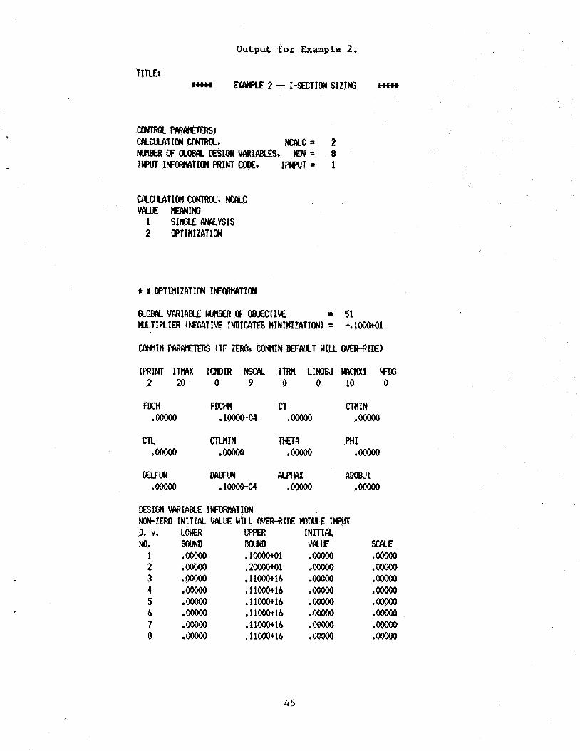
Output for Example 2.
CPLaJLATIaY COKFRQCI NuLC WE m1NG
1 SIMjtE ANALYSIS 2 OPTIHIZATION
t f OPTIHlZATION IWWTTIOII
am VARICIELE OF OB~EMIM = 51 MATIPLIEF4 (EIEGATIM INDICATES HINIHIZATIONI = -. 1000+01
IRNT ITWX ICNDIR FIsccll ITRM LINOBJ FlcKmxl rX; 2 20 0 9 0 0 10 0
cn CTLHIN PHI ,00000 ,00000 .w .m
ESIM VARIABLE IffORMTION W Z E R O INITIAL VIVUE WILL OVER-RIIIE W W IN)uT D. V. L M UPPER INITIAL No. BOUND 8ouND WE
1 ,00000 . l m 1 .00000 2 .w .2ooaiho1 ,00000 3 .90000 11ooo+lb .00000 4 ,00000 .11000+16 ,00000 5 ,00000 .11OOO+16 .ooo(x) b ,00000 .11OOO+16 ,00000 7 .m .11W16 .00000 8 ,90000 .11000+14 ,00000
45
1 2 3 3 a 4 5 s b 6 2 7 38 8 8 3p 9 1 22
10 4 34
16 12 12 12 0 16 13 13 16 0 16
TMIY,
1 1 EX
83 147
46
+ + + + + + + + + + + +
+ + + P O S T O P + + +
+ + + + + * + + + + + +
+ + t + LocKHmf fiEoRGIA coI9W + + + JJE 1983 + * * +
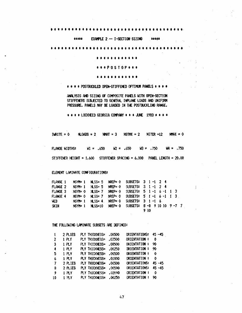
IlrRITE=O K W = 2 W T = 3 NSTnX=2 NITER42 WX=O
STIFFEM3 HEIGHT = 1.600 STIFFENER P)RcING = 6.000 P M L LMGTH = 20.00
ELEt!€NT L M I M T E COIYIGLIREITIONS:
1 2 PLIES 2 1 PLY 3 1 PLY 4 1 PLY 5 1 PLY 6 1 PLY 7 2 PLIES 8 2 PLIES 9 1 P L Y
10 1 PLY
ORIENTATIONS: CRRIENTATION : ORIENTATIOH : ORIENTATION : ORIENTATION : GRIMTATION : MI ENTATIONS: MIIENTATIONS: INENTATION : ORIENTATION :
45 -45 0 90
0 0
9o
45 -45 45 -45 0 90
47
k8
rn=L I W = O N O B W X = O IW=O wx = o w = o NSEP = o
cw)LI€O LOCIQS (FOR#/WIT WIDTH): = -9OOO. NY t 0. NXY * 900.
pREssu;6:= e o 0 TEERAW DIFF. = 0.
INITICY EGCM./CENGM = .0010 AXIAL LW ECCEN. = .oooO
S U E T HAlEflICY SPECIFICATION:
SUBSET 1 MTERIAL NO. 2 SUBSET 2 MTERIAL NO. 2 SUBSET 3 MTEAIAL FK). 2 SUBSET 4 MTERIALYNO. 2 SUBKT 5 MTERICY No. 3 SUBSET 6 MTERICYNO. 2 SUBsn 7 MTERICKND. 2 S U E T 8 MTERIALNO. 2 sms€T 9 MTERIALHO. 2 SUB'S43 10 WlTEAIlY NO. 2
49
INITIAL ECCEN,/LMGTH = .W10 flXIcU. LW ECMI. = .&NO
50
I(ME DESCRIPTICU 1 2 3 4 5
1 2 3 4 S 6 7 8 9
19 11 12 13 14 15 16
SHRR STIFFFESS LONGIT. STImEsS SKIN STRWjTH SfibCIIN LIHITCItIM L. NM;E: STRENGTH R. RcrNGESTRENGTH ClEB s m m STIF. LOCAL BWXLING SKIN LOCCY BUCKLING RrJUIW BuCxtIW TDRS./FLEX. BlCKLING EUCER BUCKLING SKIIUSTIF. INTERFIICE SKIN LAW (LONGIT.) SKIN LAYUP 1 INlERtl, 1 SKIN LAW ~TRANSV.)
,679 1 026 1.097
* 192 1.420 1.420
99.OOo 1.382 99. ooo 2.336 2.290 ,332
99.# 1.791 ,240 .395
679 1.026 2.2M .331 1.749 1.749
99.OOo 3.005 434
4,645 4.973 1.200 99.ooo I.791 ,240 ,395
HINIIIUIJ W I N OF SAFETY = ,192
I
51
ITER= 2 ow= .14536*01
mrsm VP~(IAB~ES (X-MCTOR) 1) .bQq7oaoO .1723941 .47&942 ,214291-01 .9984Q-02 ,47410-02 7) .48131M ,1819561
141 14-01
c
a -. -.25tMl -.l -.39850+01 -.l -. 1863628W 1731241 -. 51
5 2
ITER = 4 oBJ= ,1411441 No CHcYJcf I N OM
CfMlsTRRIKl V M E S (G-KCTOR) 1) -.4985491 -.9229191 -.3454891 -.25164-01 -.11973+02 -.I197392 7) -.70801-01 -.12692+01 -.3985091 -.11825+02 -.53428+01
13) -.99W+O3 -. 18628+02 -. 1731291 -.51oO(kol
ITER= 5 ow= 1410591
EGISION VMIABLES (X-MCTOR) 1) .60359+00 ,1923791 ,3561842 .2630&01 .10152-01 .40760-02 7) 046550-02 .1&975-01
CONSTRAINT V M E S (EKCT(IR1 1) -.49764+01 -.923&491 -.34474+01 -.2!%5-01 -,1196b+02 -.11966+02 7) -.99ooo+o3 ,24414-02 -.126ato1 -.m73+0i -.iim+02 -.mwoi
131 - . m 3 -.18449+02 -.17176+01 -.50983+Ql
ITER= b OM= .14097-01
DECISION VARIABLES (X-VECTOR) 1) .#101+00 .19095+01 ,3531742 .26363-01 ,10171-Ol .40321-02 7) '46459-02 .19071-01
OoHsTRCllNT VCKUES (G-VECTOR) 1) -.49249+01 -.92831+01 -.34047+01 -.25404-01 -.11852+02 -.11852+02 7) -.99000+03 -.21973-01 -. 12618+01 -.3?492+01 -. 11533-02 -.50626+01
13) -.99ooo+O3 -. 1877242 -. 16376+01 -.50867+01
ITER= 7 ow= ,1405b-01
OECISIM VMIWS I%-KCTOR) 1) 5T38+00 ,1875291 .34213-02 .26645-01 .10273-01 38792-02 7) .46324-02 .19347-01
CXHSTRAINT VALES (G-VECTOR) 1) -,47587+01 -.34231+01 -.32731+01 -.22722-01 -.11527+02 -,11527+02 7) -.9WOO+O3 ,2441442 -.12386+01 -.38824+01 -.10754+02 -.44017+01
13) -.PP000+03 -. 19141to2 -. 13957+01 -.506M+o1
53
wws 1) 71
131
fm= 10 m= .1~15-01
54
ITER= 12 oBJ= .13887-01
c
mIsIas WIAIABCES (X-KCTOR) 1) .wm .18402+01 .32242-02 . m 1 .1104941 . 2 8 9 w 7) ,45117-02 .M163-01
ITER= 13 OBJ = .13815-01
ECISION VARIABLES (X-VECTOR) 1) .53542+OO .17995ro1 .29806-02 ,32955-05 .12198-01 ,2581742 7) .47929* .2034241
GWTRAIKT VCYES (G-VECTOR) 1) -.3&81+01 -.10156+02 -,25946+01 -.4888341 -.11289+02 -.11289+02 7) -.99000+03 -.26611rM) - . 7 8 7 W -.34259+01 -.E39491 -.34595+01
13) -.95+000+03 -.21128+02 -.30824-01 -.53022+01
ITER= 14 OW= ,1379341
DECISION VARIWS (X-VECTOR) 1) .53517+,00 .17988+01 .29793-02 .32948-01 .1219641 .25802-02 7) .47#3-02 ,20287-01
IXNSTRAINT VALES (GMCTOR) 1) -.34519+01 -.1011292 -.25245+01 ,12994-03 -.1118592 -.11185+02 7) -.99000+03 -.21729rM) -.7mo+rx) -.33716+01 -.61714+01 -.343&901
13) -.SWI+03 -.21102+02 -.43121-01 -.53314+01
ITER= 15 OW= 13787-01
, COMSTRAIKT VcllllES (G-VECTOR) 1) -.34311+01 -.10113+02 -.25277+01 -*12836-01 -.11335+02 -.11335+02 7) -.99000c03 ,24414-02 -.71021+00 -.31451+01 -.61598+01 -.3b2W1
13) -.99000+03 -,21118+02 -.30377-01 -.53440+01
5 5
1
1 -.p9402+01 -.2 - 3 -.43701*00 -.7 - 03 -.20725+02 -.
ITER= 18 OM= .1w1-01
l[TEa= 19 OW= 13593-01
DECISIOH WlRIABLES (X-ECTUV 1) .51583+00 .18643+01 ,2480942 .4236(-01 .lbb82-01 .I725642 7) .53304)-02 .19269-01
a
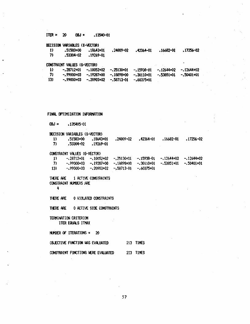
FIN& OPTItlIZATION INFI#WCITION
DECISIoFl VARIc\BLES (X-VECTOR) 1) .51583tOO .18643+01 ,2480942 ,4236441 .lbb%241 .1725642 7) .53304-02 .1926941
coF(sTRAINT VALES (GVECTOR) 1) -.2871241 -. 1005242 -.251W1 -. 15938-01 -. 12644+02 -.12644+02 7) -.99000+03 -.19287+00 -.1889$+0 -.3011041 -.53851+01 -.SO40141
13) -.WWO+O3 -.2#0342 -.58713-01 -.&0373+01
THRE PRE 1 ACTIVE CONSfRAIHTS r n r n I N T )(IRIBERs ARE
4
TFERE ME 0 V I W I T E D CONSTRAINTS
MliE ARE 0 ACTIVE SIE 4XNSTMINTS
'FEw1INCITIM3 CRITERION ITER E M S IWX
OBJECTIM W T I I X ( MAS EV4MTED 213 TIES
5 7
ran .1 1
1 1 2 2 3 3 I 4 5 5 4 b 7 7 8 8 9 1
10 4
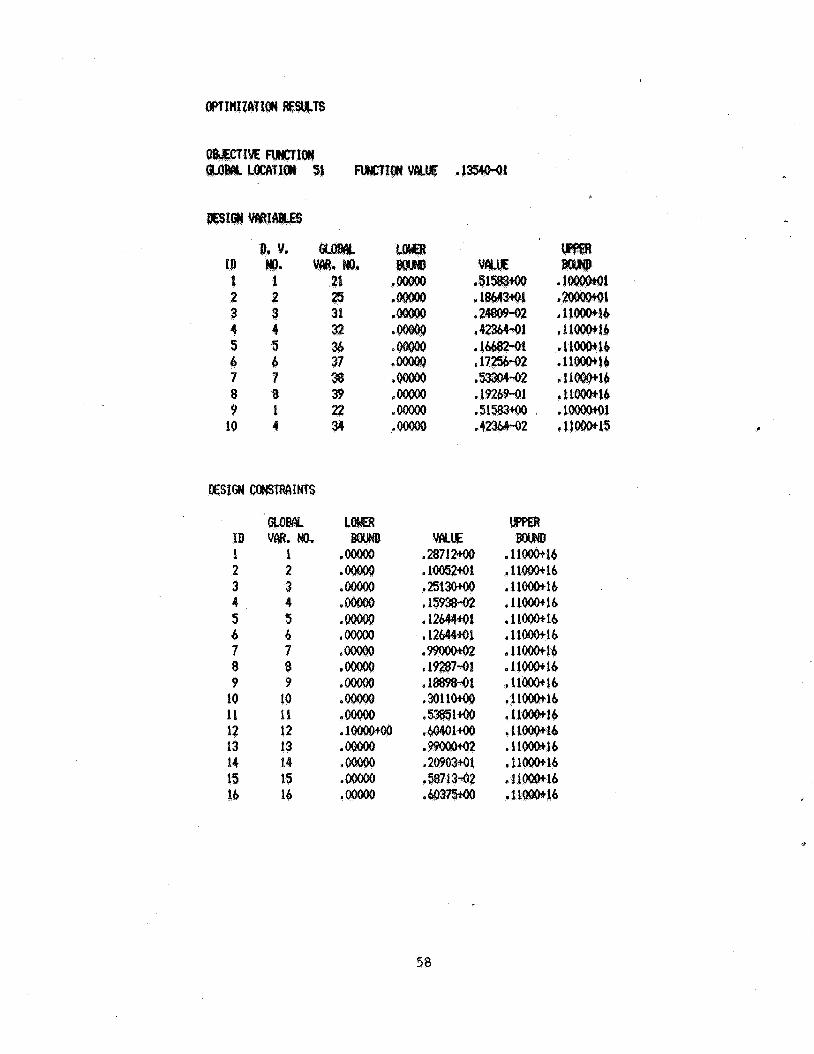
KSIGN IMS
GI,oBAL ID VAR. No. 1 1 2 2 3 3 4 4 5 5 tr b 7 7 8 8 9 9 io 10 11 11 12 12 13 13 1 1 1s 15 16 16
L
Q
58
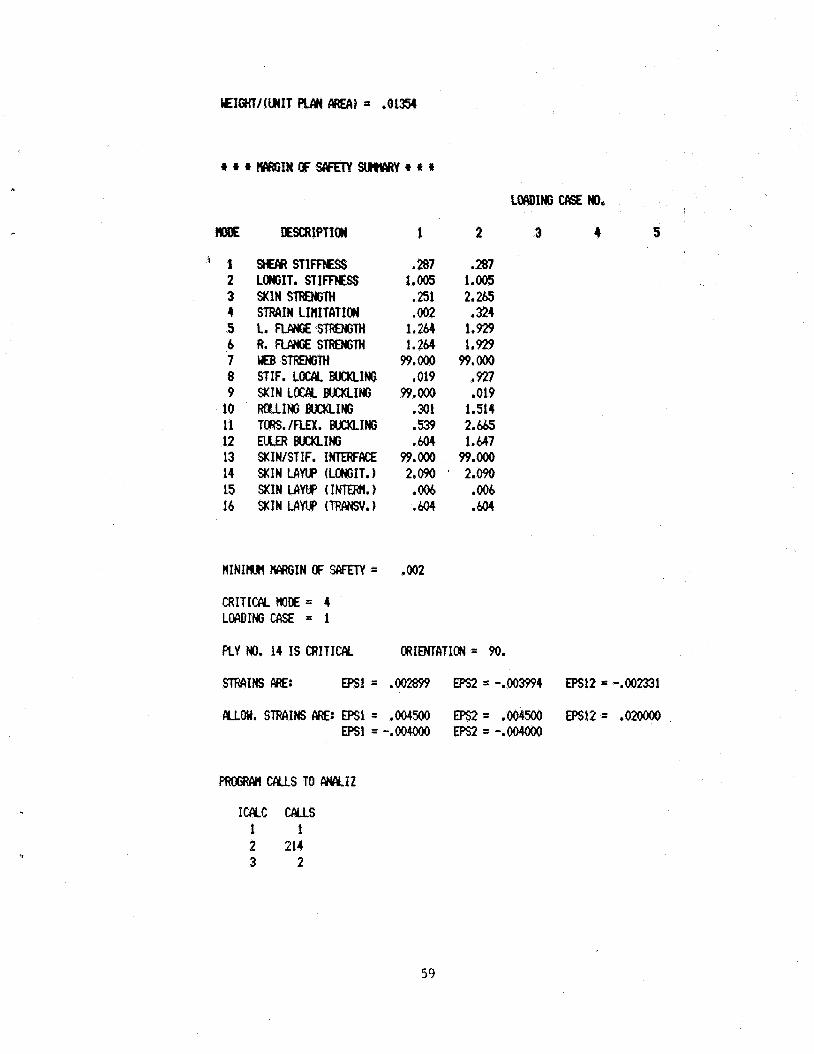
‘ 1 2 3 4 5 b 7 8 9 10 11 12 13 14 15 16
SHECJR S T I m E S s LONGIT, STIFFXSS %IN STRENGTH STRAIN LIHITFITICM L. RAN# smTH R. RpmjE STRENTH WEB smTH STIF. Loc/y BUCKLING SKIN LOUY BUCKLING ROUING BUCKLING ToRS./FLEx. W I N G NLEA BUCKLING SKIWSTIF. INTERFIX€ SKIN LAW (LONGIT.) SKIN LAW (INTERN.) SKIN LAW (TRANSV.)
,287 1.005
* 251 .002 1.264 1.264 99.OOO
,019 99.OOo
s 301 ,539 .b04
99. Ooo 2.090 ,006 ,604
,287 1.005 2.265 .324 1.929 1.929 99. OOO
,927 ,019
1.514 2.645 1.647
99.Ooo 2.090 ,006 .b04
3 4 5
CRITICPLW)t€= 4 LoAI)INGG%E = 1
PLY No. 14 IS CRITICIY ORIENTATION= 90.
m1NS ME: mi = .oom EPs2 = -.oo3994 EPsl2 = -.002331
ICCYC W S 1 1 2 214 3 2
59
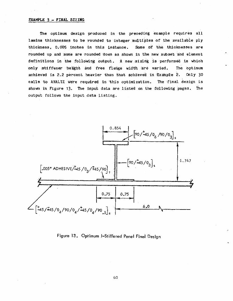
The optimum
lamina t h i c k n e s s e s to e k n e s s e s are
s u b s e t and e l e m e n t
d e f i n i t i o n s i n o u t p u t . A new si
t h e a v i e r t h e n
shown i n F i g u r e 13.
Figure 13, Optimum I-Stiffened Panel Final Des ign
60
a
INpuTaATI\: pI\GE 1 L IE
i u l B € R U I I I I I I U I I I I I I U L I I I . . U U . I DATA *(~~+t-wuu+wwf+++w
1 +WH E X W E 3 - I-SECTIM FIN& SIZING
2 2 2 1 c.....AEcORD s2 - m cx))ITRoL PWCYETERS: N c c y c I w v , I m
C.....AEcMu) 53 - OPTIWIZ4TIOH COHTROL INTEGEfl PARCYRERS:
3 2 2 0 0 3 0 0 1 0
4 0. .m1 5 0. .ooOol
6 3 51 -1.
C IPRINT, ITIYIX, ICNDIRvNSCALv ITF~~LINOBJIWHX~
C. e.. RCORD 54 .. OPTIH. CONTROL FLMTING POINT PAWKER!+ RlcH,FDcHI
C.....REcow) S5 - WTIK C. * .Ecow) $4 - BclSIC OPTIHIZATION INFORMTION: NDVTOT, IOBJ~SCNOPT
ROIITING POINT PIYWETERS: WNNIDAWM
C.. . . .REPEAT RECORD S7 NDV TIES C.....ECORD s7 - DESIGN VARIABLE Bourns: W,wB 7 0. 1.0 ' % W(1) 8 0. 2.0 % H C.....REWIT RECORD S8 MWTOT TIES C. .RECORD 58 - DESIGN VARIABLE IWITIFICATION: NDSGNI ID9XWIIUT
9 1 21 % W(11 10 2 25 % H 11 1 22 % W(21M1)
12 3 C.....ECORD s9 - NuFlBER OF CoNSTRclIHl SETS: NCIWIS
C.....EPEIIT RECORDS S1Q AND Sll Ncc\)Js TIERS C.....WcoRD Sl0 - CONTRIMS SET IDENTIFICATION: ICO)(,XONIKCON
13 1 11 % COHSTRCIINTS 1 - 11 C.....REcoRD Sll - CONSTRAINT SET BolrNIfs: BLiW
14 0. l.El6 15 12 12 % m 1 N T 12 16 0.1 LE16 17 13 16 % CBNSWIKTS 13 - 16 18 0. LE16
19 SIZ
20 0 2 3
21 .50 .50 .75 .75 1.8 6. 20.
C.. . . ,RECORD S12 - END OF SIZING DATcl
C.....FECORD A1 - ANcllYSIS ClWJiRDL DATA: IkB(ITE,NLOPIIS,ET
C.....MURD A2 - G E M l R Y : WII),W(2)~11(3),W(4),HI~~XL
C.. . . .REPEAT RECORDS A3 AND A4 Fofl ECICH NONZERO RATE ELEm C.....RECORD A3 - PLATE ELMENT S M T R Y AND R W A T INDICATORS: NSmtNS,W
2.2 1 s $ W(1)
23 3 1 2 3 6 24 1 5 $ W(2) 25 3 1 2 3 6 26 0 5 $ W(3) 27 5 1 6 - 1 3 28 0 5 $ W(4)
C... . .MCORD A4 - WTE UMaFl SUM IDOJTIFICATION WlBERS: LS
61
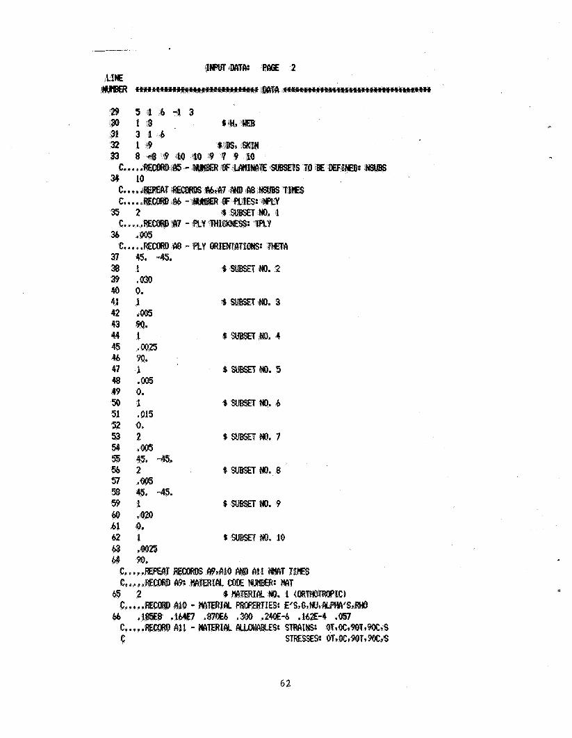
41 1 42 .W 43 *w.
I .m25
46 47 4% .m 49 0. 50 .1 51 5 52 5 3 2
w. 8
. 9
62
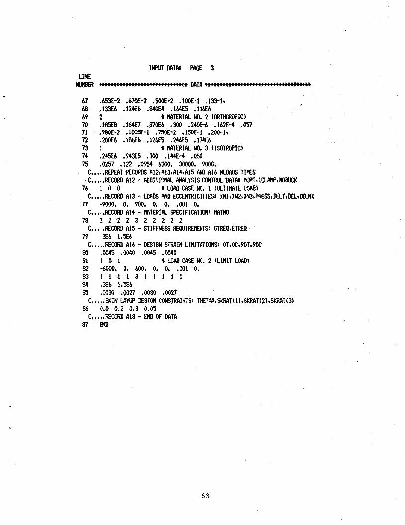
6 3
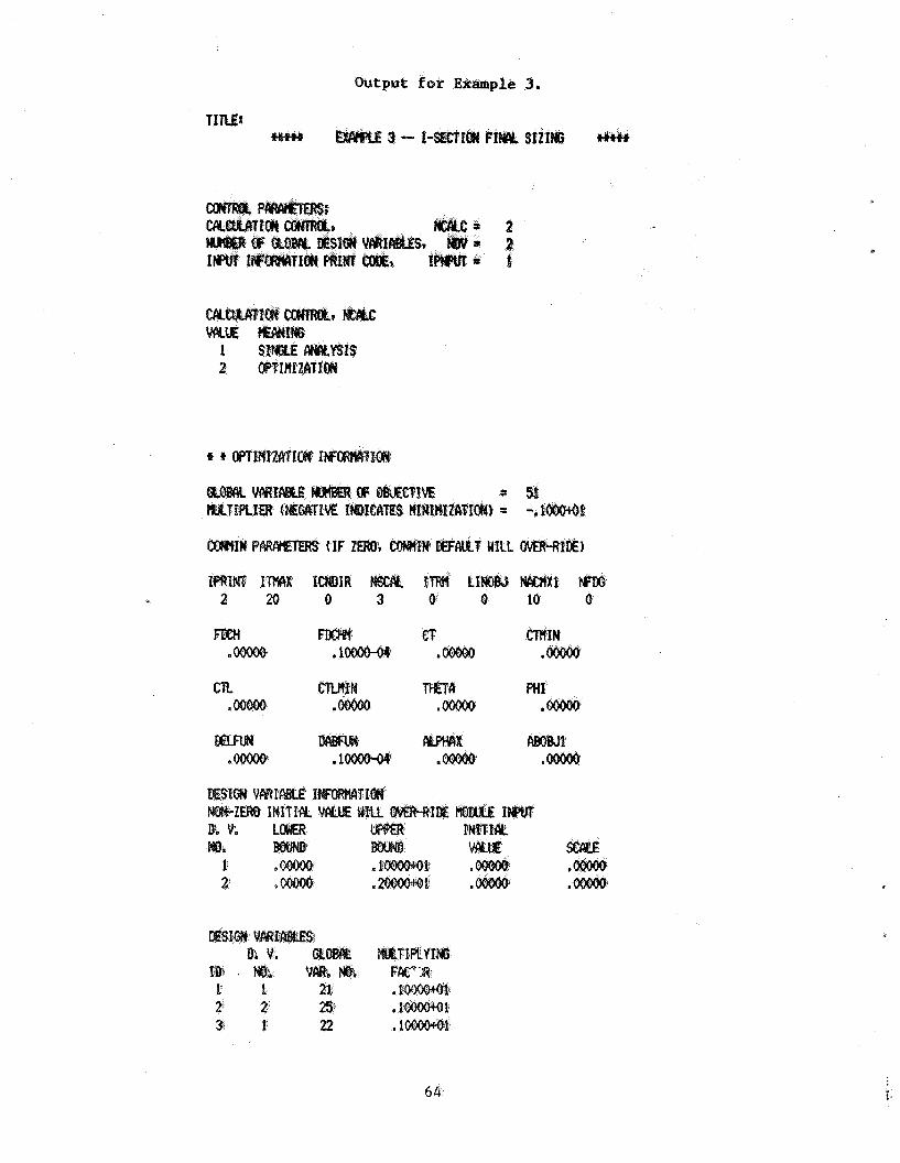
Output for Example 5.
= 3 P = -.E
64 i-
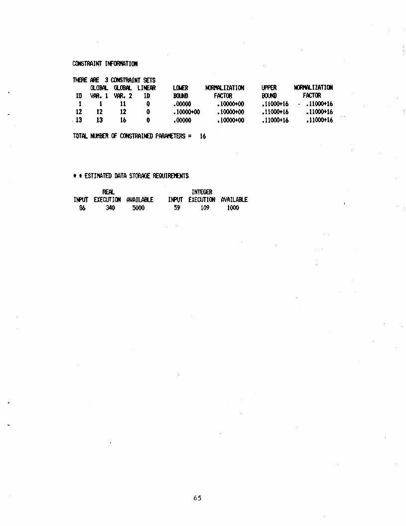
TtUElIAE 3COHS~INTsETS am am LIW LafR WwZtwIZATION upwl NocwEyIzaiIau
ID VCIR. 1 VIIR. 2 ID BabB) FACTOR WXHD FACTrn
12 12 12 0 8 1- e 1- 11001k16 .11000+16 13 13 16 0 .m a 1- ,11001klb . 11000+16 1 1 11 0 .moo loooo+Oo .11001k16 - m11000+16
TOT& M B € R Cr CONSTRIIIHD PCWWETERS = 16
Rw. INTEGER IEPUT MEWTION #flILABcE INWC EXECUTION NAILABLE
86 340 5ooo 59 109 loo0
65
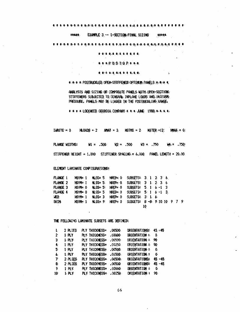
t f t + i * t 4 t 4 t f E f 4-4 +,t t-t t t t t t 9
IWR;I'TE-= 0 M.OAD$= 2 = 3 . IJsT)Q(=2 NITER =42r
5 5 $ 3 1 2 3 6 5: 5
9 0 W T S : 8 -9. 9 10. 10 9 7 9 10
1 2 PLIES
10f 1 FLY
L
66
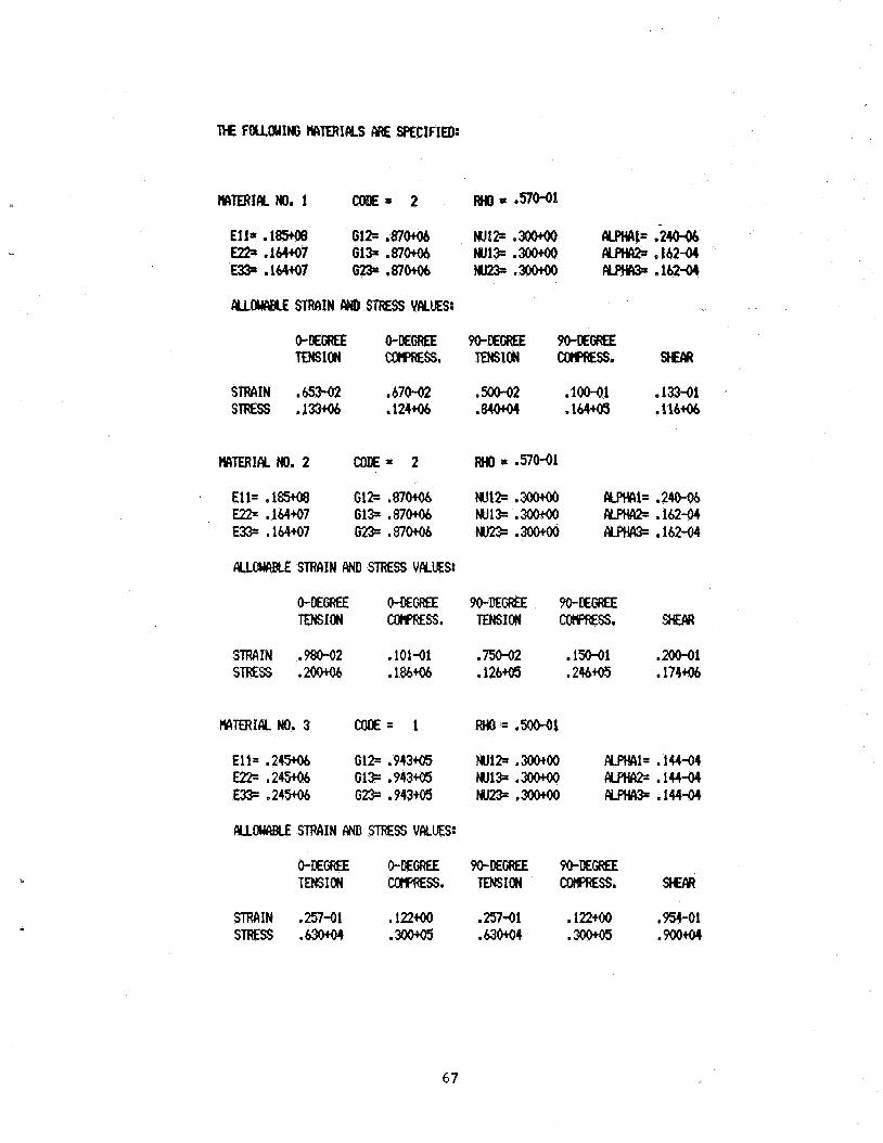
U W A U STWIN IWD STRESS VALUES:
UOClRBLE STRAIN AND STRESS VALUES:
STRAIN ,980-02 .101-01 ,750.02 150-01 .2oM)1 STRESS .2oo+o6 .186+06 .126+05 ,2464.B .174+06
MTERIAL No. 3 con€= 1 RHO= .500-01
Ell= . 2 4 W 61% ,943- Nul* .moo ALPHIIl= ,14444 E22= ,24306 Gl+ .943+V5 w133.300+00 wINcI2= .144-04 E33= . 2 4 W #= .943+05 w23= '3o040 cypHcI3= ,144-04
FYLOWABLE STRAIN iM) STRESS VALUES:
67
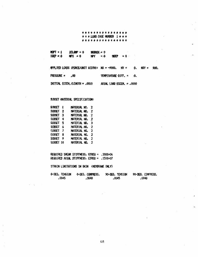
6%
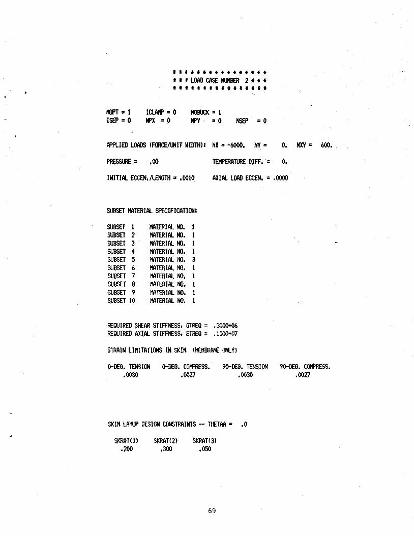
+ + + + + + a + + + + + + * + +
' t + t + + + + + * + t + + + + + 4+tLWCASENUlWER 2 + t +
m=1 I W = O KlBucK=l IW=O wx s o WY = O NSEP = O
WflIED LW (FORCE/WIT YIDTHIr NX = -6000. NY = 0. N X Y = 600.
PRESSURE= .oo TEIIPERIINRE DIFF. = 0.
INITIEY. ECCEN./LENGTH = ,0010 AXIlY LW EEEN. *oooO
IYITERIALYNO. 1 MTERIRLHO. 1 IYIT€RIALNO. 1 rylTEf?If%Ho. 1 MTERIAL NO. 3 MTERIAL NO. 1 HATERIALNO. 1 MTERIcY No. 1 WlfERIcYNo. 1 MrnIALHO. 1
STRAIN LIRITRTIQNS IN SKIN (HEHBRA?€ OKY)
%It4 tAW DESIGN CONSTRAINTS - THETM = .O
69
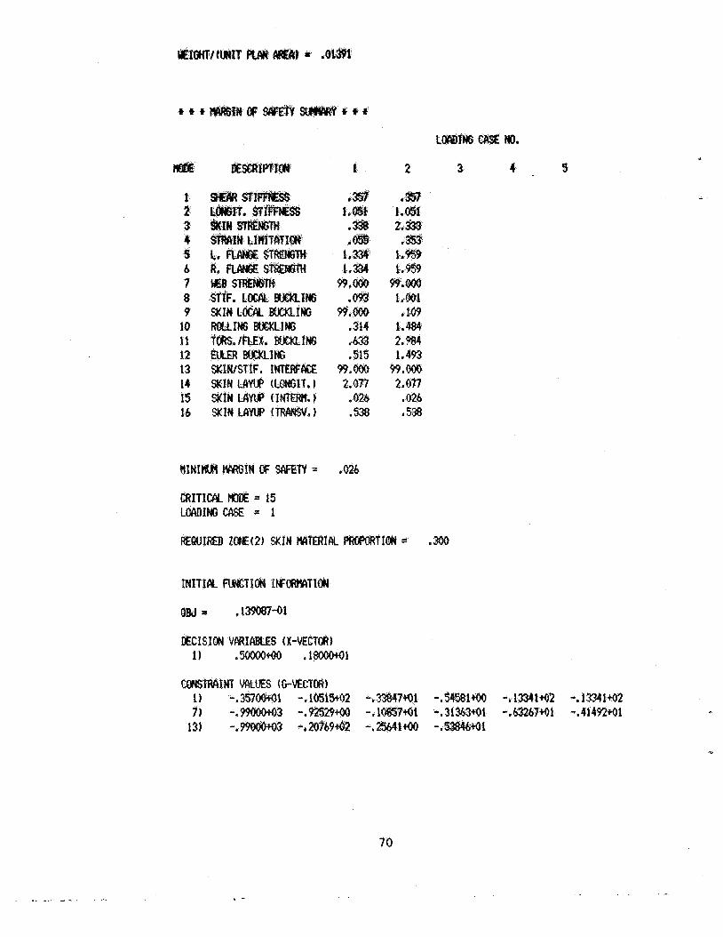
1 2 3 4 3 b 7 8 9
1.0 l i 12 13 14 15 16
,314 ,653 . St5
99.OOo 2.077 ,026 .538
. -
70
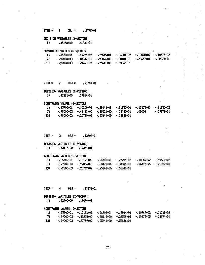
ITER= 1 om= .13748-01
OECISION VWICIBLES 4X-VECTOR) 1) . 4 b l S o .16848+01
ITER= 2 OM= .13713-O1
ECISIW VcIRIc\BLES (X-MCTU?) 1) .4239190 .178M+01
C#STiMIxT VCYUES (GVECTOR) 1) -.357oo+o1 - . l o w 2 -.m4841 -*11957m -*11355+02 - . 1 1 m 2 7) -.9WO#+03 -.44143+00 -.89521+00 -.24435+01 .00000 -.29779+01
13) -.99000+03 -.20769+02 -.2!%41+M -.53WMl
ITER= 3 OM= .13702-01
KCISION VCIRIABLES (X-VECTOR) 1) .43115+00 . 17BlMl
co)(sTRAIb(T VPLUES (GMCTOR) 1) -.3570091 -. 10191to2 -.2651ocOl -.27281-02 -. 1ob69+02 -. 1W9+02 7) -.99000+03 - . m m -.88473m -.3oo%M1 -.2441m -.2382241
13) -.99ooo+O3 -.20769+02 -.25541+00 -.SM691
ITER= 4 OM= 1369841
DECISION VCIRIABLES 4 X-VECTW 1) .427oo+oo ,174701
71
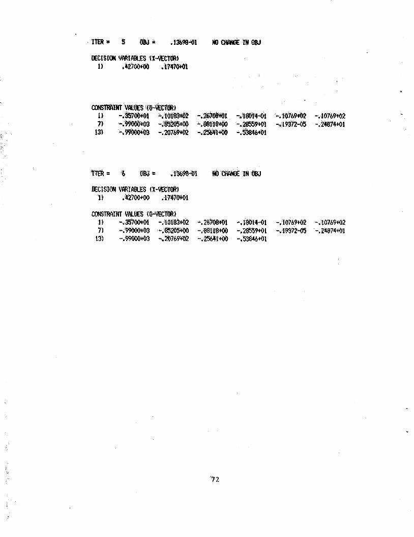
DECISION 1)
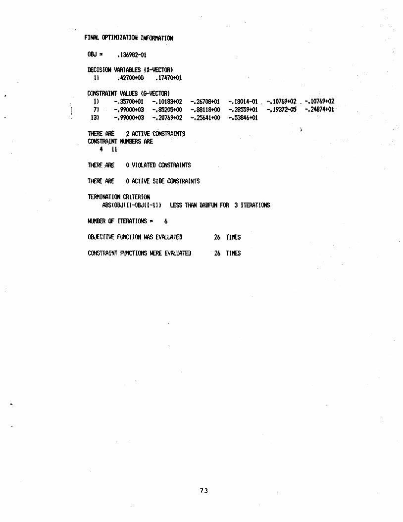
~ C I S I t u VlVtlaaLES IX-\IECTI#) 11 .42700100 .1747091
TtERE ME 0 VIOLATED CONSTWIINTS
rn ARE 0 NTIM SIDE CONSTRAINTS
OBJECTIVE FUNCTION WCIS NcywlTElJ 26 TIES
73
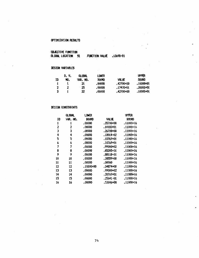
P
0. v. ID M). 1 1 21 2 2 2s a 1 22 .42700100 ,1
RQWi ID Vm. NO. 1 1 2 2 3 3 4 4 5 5 6 b 7 7 8 8 9 9
10 10 11 11 12 12 13 13 14 14 15 15 16 16
74
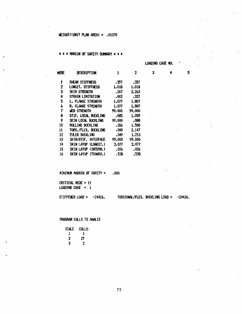
UEIGtlT/(UIIT FUW AREA) = ,01370
c
m OESCRIPTION 1 2 3 4 5
1 2 3 4 5 6 7 8 9
10 11 12 13 14 15 16
SWYI STImESs LONGIT. STIFFNESS SKIN STRENciTH STRCIIN LIHITtlTION L. NINGE STRENGTH R. RWGE STRENGTH KB s m m STIF. LOCEY BucklcImj SKIN LOCAL BUCKLING ROUING BJcKLINe TORS./FLEX. W I N G RILER BUCKLING SKIN/STIF. INTERFAE SKIN LAW (LONGIT.) SKIN MYUP (IMEWII.1 SKIN LAW (TRIwSv.1
.357 1.018
267 .002
1.077
99.Ooo ,085
99.Ooo .286 'Ooo e 349
99.Ooo 2.077
,026 .538
1.077
.m 1.018 2.263
.327 1.807 1.807 99.00
1.059 0 0 8 8
1.580 2.147 1.213
59.Ooo 2.077 ,026 .53%
CRITICAL M E = 11 LOAOINGeCISE = 1
STIFFEt€R Locu) = -24426. TORSIONAL/FLEX. BlCKLIHc L# = -24426.
I W C CALLS 1 1 2 27 3 2
7 5
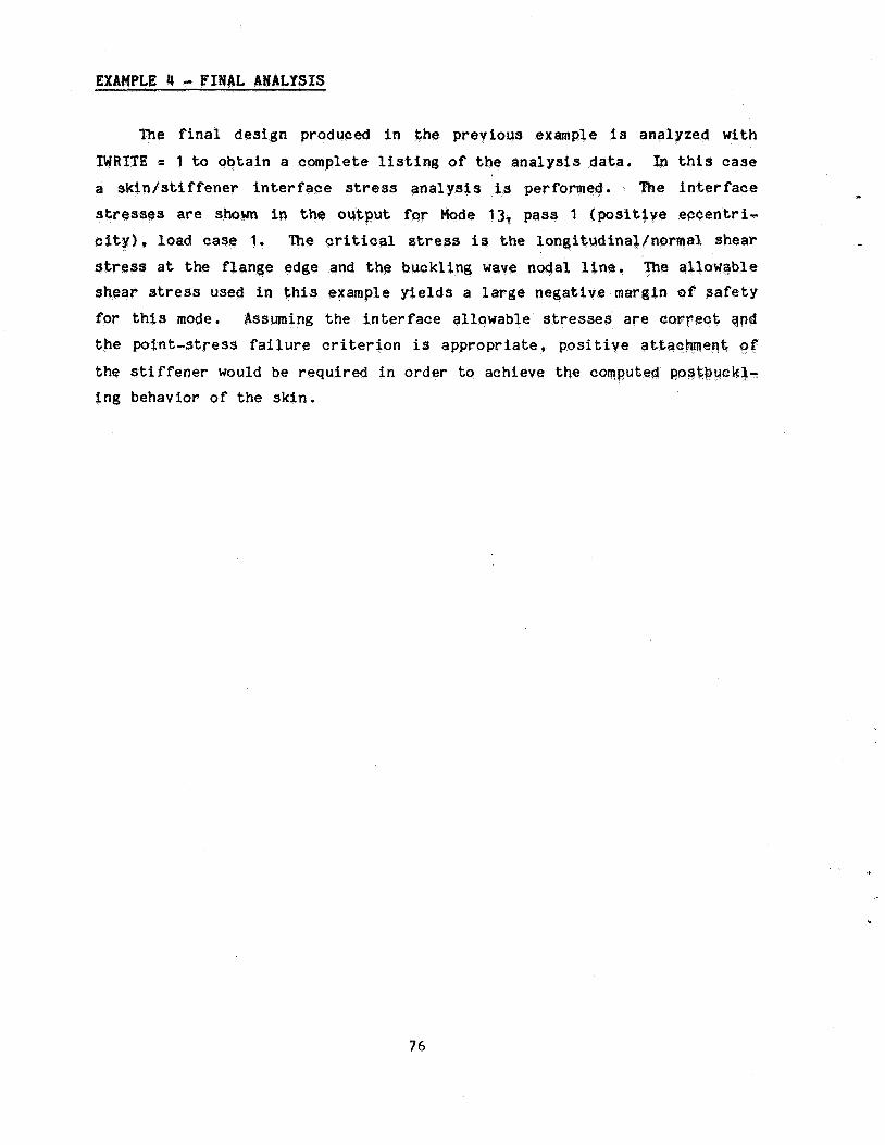
EXAVPLE 4 - FINAL ANALYSIS
The f i n a l d e s i g n produced i n e p rev ious example is ana lyzed w i t h
TWRITH = 1 to o b t a i n a complete l i s t i n g of t h e a n a l y s i s data. In t h i s case a s b i n t s t i f f e n e r i n t e r f a c e stress a n a l y s i s is perfor The i n t e r f a c e
s are s i n the o u t p u t for 13, pass 1 ( p o s i t i v e e w e n t r i - c i t y ) , l oad case 1. The crit ical stress i s t h e fong i tud ina l /no rma l shear
s a t t he f l a n g e edge and the buck l ing wave nodal l intz. The allowable s h e a r stress used i n t h i s example y i e l d s a large n e g a t i v e margin of safe ty
for t h i s mode. Assuming t h e i n t e r f a c e a l l a w a b l e stresses a r e
t h e p o i n t - s t r e s s f a i l u r e c r i t e r i o n i s a p p r o p r i a t e , p o s i t i v e a t
t h e s t i f f e n e r would be r equ i r ed i n o r d e r to achieve t h e co tq~q ted ~oskbuokL- i n g behavior o f t he s k i n .
76
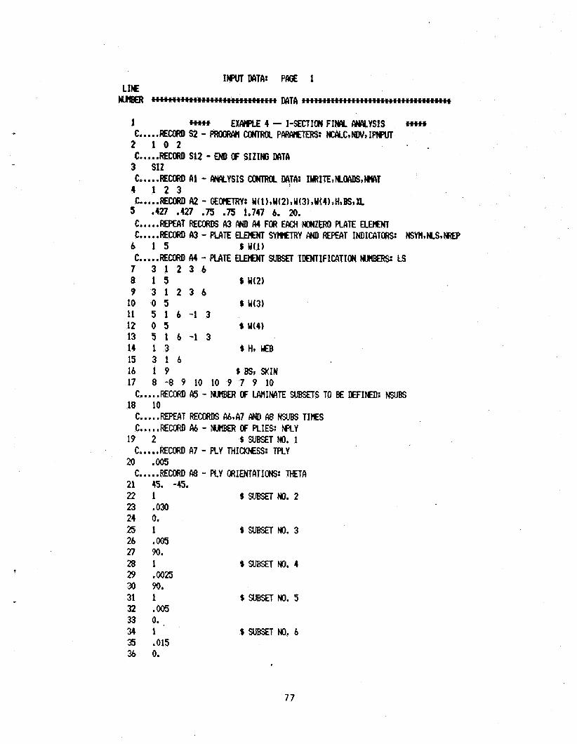
c
1 c.....R€cuu) s2 - PRoGRCyl CaJTROL P l l R A E m 3 H c c Y c * N w , 1 m 2 1 0 2 C.....flECtNI S12 - EM OF SIZIHG DATA 3 SI2
4 1 2 3
5 e427 0427 .75 .75 1.747 6. 20.
EXA)IPLE 4 - I-SECTION FIW W Y S I S
c.....w~cow) a i - MYSIS cowl~u DATA: IWRITE~NOCIDS,WT
C*..-.Em A2 - GE- W(l)tW(2)*W(3)*W(4),H*BS*XL
C.....REKAT WCUU6 A3 MI A4 FfX EAc)I NONZERO PLATE ELW C.....RECU?D A3 - PLATE ELEt€NT SYmTRY AND EPEAT INDICATORS~ NSYH*NS,NROP 6 1 5 L W(1) C..,..REc[IRD A4 - PLATE aaaCr SUBSET IDMTIFICATION MJtlKRS LS
7 3 1 2 3 6 8 1 3 L W(2) 9 3 1 2 3 6 10 0 5 % W(3) 11 5 1 6 - 1 3 12 0 5 % WO) 13 5 1 6 - 1 3 14 1 3 % H, LEB 15 3 1 6 16 1 9 0 BS* SKIN 17 8 -8 9 10 10 9 7 9 10
18 10 C.....REcoRD A5 - NuItBER OF UVIINPITE SUBSETS TO E€ DEFIED: NSURS
C.....MPEAT RECCRDS &*A7 Aw A8 WJBS TIES C.....REclRD A4 - NWIER (w: PLIES: M Y
19 2 $ S U E T N O . 1 C.. . .RECORD A7 - PLY THIMSS: TPLY
20 .005 C.....REcopD A8 - FLY ORIENTATIONS: M A
21 45. -45. 2 2 1 %sllssETNo. 2 23 ,030 24 0. 2 5 1 LsllBsETNo.3 26 ,005 27 90. 2 8 1 %SUBSETNO. 4 29 ,0025 3 90. 31 1 %suBsEiNo.5 32 ,005 33 0. ,
3 4 1 %sussETFIo. 6 35 ,015 26 0.
77
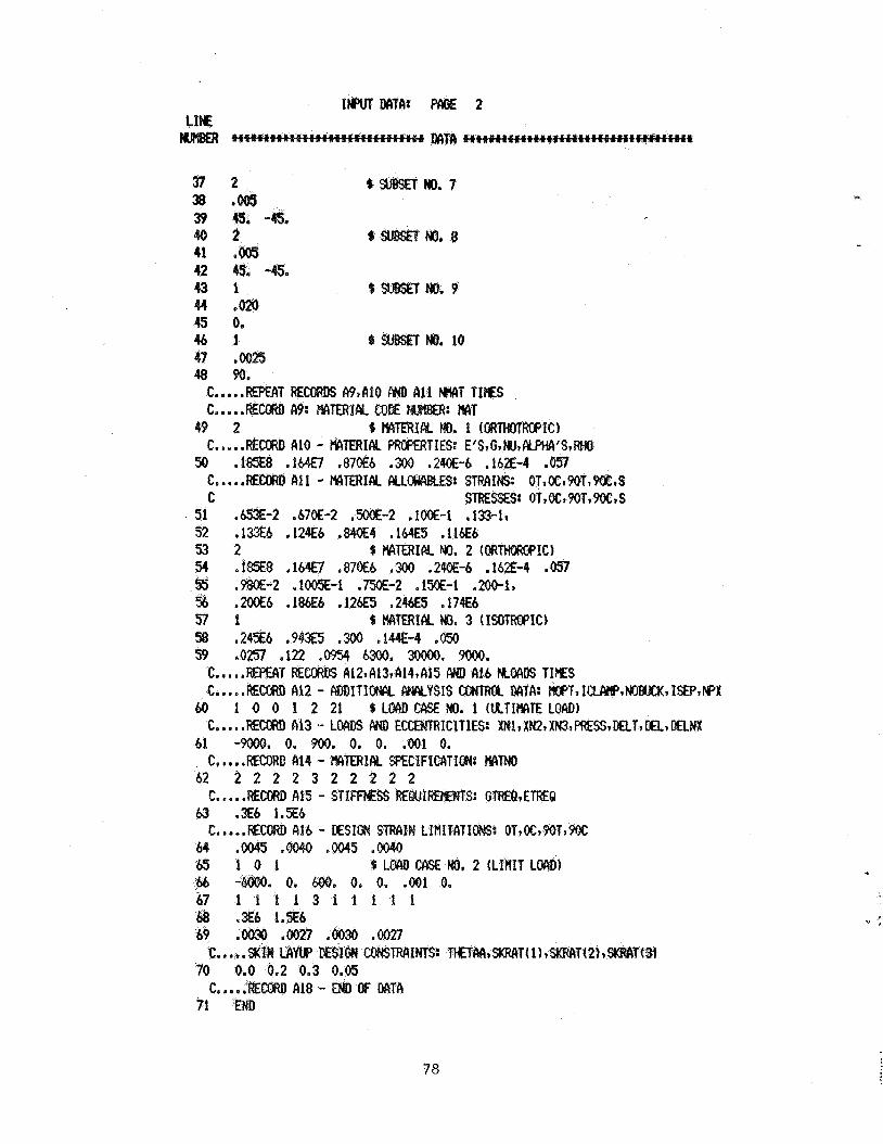
78
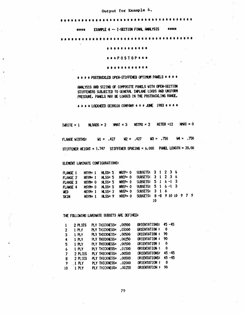
Output for -pie 4.
+++f+ E X W 4 - I-SECTIOW F I N CWCYYSIS ++t+t
+ + + f + f f + + t + f f + + + + f + + + + + + + + + + + + + + t + ~ + + 4
1 2 PLIES 2 1 PLY 3 1 PLY 4 1PLY 5 1 PLY b 1 PLY 7 2 PLIES 8 2 PLIES ? ,1PLY
10 1 RY
PLY T H I M S - PLY THHIcxtESs. PLY THIMoJEsst PLY THIcI(NEss= PLY T H I C M S RY THICXNESS. PLY THICKHESS. PLY THICKNESS= PLY THICK)yS- PLY THIcKEEss=
t + * P O S T O P t t +
) + + + * + + I f + + +
M I T E = 1 K W = 2 H I F I T - 3 NSMX-22 NITER=12 WX.r0
flANciE1 NSWl N S - 5 - 0 SUBSEIS: 3 1 2 3 6 RAtJGE2 MSYWl N S - 5 W O SUBSETS: 3 1 2 3 6
RANGE4 NSYrC.0 KS-5 NRE15’=0 SUBSETS: 5 1 6 - 1 3 WEB HsMI=l K S 3 - 0 SJBSETS: 3 1 6 SKIN NSW1 KSS=? WP=O SUETS: 8 - 8 P1010 9 7 9
RANGE3 % Y k O KS9S W - 0 SUBSETS: 5 1 6 - 1 3
10
OflIENTATIONS: ORIENTATION : ORIENTATION : o R s m m O w : ORIENTATION : ORIENTilTIEAI : ORIENTATIONS: OR ENTAT I OHS: ORIENTATION : ORIMATICM :
45 -45 0 90 90 0 0
45 -45 45 -45 0 90
79
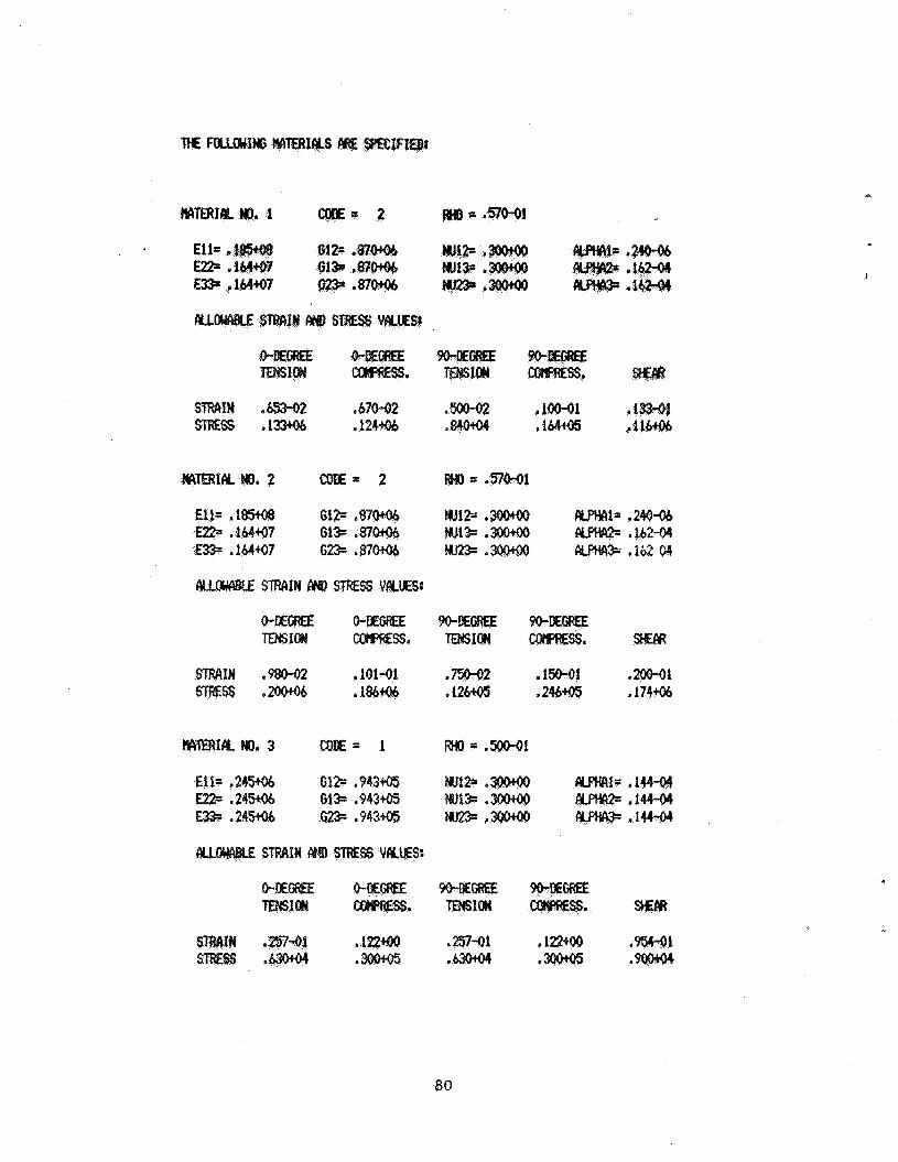
E l 1= E22. E D
0
Ell= 9245% G12= ,943+05 m l s : .144-0?1 m- ,24306 G13= ,943- &flw= ,14444 E 3 3 .24306 623. ,94395 ikFti#= ,146-94
. .2n-01 .122+00 . . .#u+@l e
80
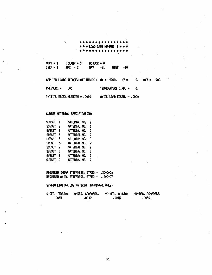
m=1 I W = O NOBUCX=O I W = l wx . 2 w =21 H#3 =10
m w = .oo TDo)Ew1TuIE DIE. = 0.
gasET WTERICY SPECIFICATION:
SUBSET1 SUBSET2 s u B s R 3 SUBSET4 SUBSET5 SllgSETb SUBSET7 S U E T 8 SUBSET9 SUBsn 10
~TmIFY. No. MlERIFY. No. M r n I Y No. MERIM. No. MrnIcy, Ho. MTERIFY. No. MTERIFY. No. ryITERIIy No. tlAlERIcv Ho. MTERIFY. No.
2 2 2 2 3 2 2 2 2 2
STR4IN LIHITCITIONS IN SKIN (hEtW?At€ MY)
0-DEG. TENSION 0-DEG. COrpRESS. 9o-EG. mJsION WDEG. CGWIESS. ,0045 .oO40 .OMS .0040
I .
81
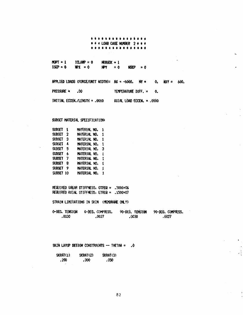
t * t # t # i * t % t t t f f f
t 4 t t t * t t f t f * t * t f * + t L O E U ) 2 a t r
4
= 0. my= . . = 0.
. = ,
a2
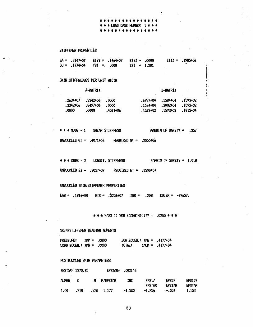
t t t t t t t t t t t + + t t t
~ ~ + L o c u ) c c \ s E ~ I * * * t t + t + + t t + t t t t + t i
EA = .3147+07 EIW = .1464+07 EIYZ = .oooO EIZZ = . l W G J = .1774+Q4 YST = .ooO ZST = 1.201
1 I I
SKIN STImEssES PER UNIT WIDTH !
I lI-?wRIX D-t#lRIX
,2634+07 .3342tQ6 .oooO .6987+04 .158494 .1593+Q2 .3342* .8497* .oooO .1584+Q4 .3002tM .1593+02 .oooo .oooo .4071% .1593+02 .1593+02 .181594
tt+FIoDE=l SHEARSTIFFNESS WINOFSMTY= .357
t t t MDE = 2 LOHGIT. STIFFNESS W I N OF SAFETY = 1.018
UIBlrCKLm SKIN/STSEEWt PROPERTIES
EAS = .1816+08 EIS .5256+07 ZBR = .2Q% EUER = -79657.
t t t P&S 1: Bow ECCEHTRICIM = .Om t * t
mssuRE: x H P = .QQQQ BC4 E W . : XK = .4177+04 COADECCEN.: X t l N = .oooO T O M : XtJon = .4177+04
xNsTRR= 5370.65 EPSTCIRS .0021#
m D n FIEPSTPA XNX EPS11 E 2 1 EPs121 EPSTPA EPSTM EPSTCIR
1.00 .810 ,128 1.177 -1,380 -1.856 -. 054 1.153
8 3
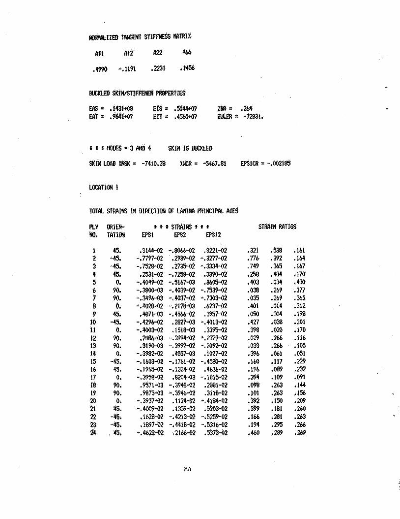
IZB STI IX
At 1 412 #6b
.4m -*I191 e2231 '14%
* * f = 3
1 45. 2 -45. 3 -45. 4 115. s 0. & 90. 7 90. 8 0. 9 45.
10 -45. 11 0. 12 90. 13 90. 14 0. 1s -45. 16 45. 17 0. 18 90. 19 90. 20 0 . 21 45. 22 4% 23 -45. 24 . 45,
,314942 -.806&-02
- . E M 2 ,273542 ,2531-02 -.7*02 -,4049-02 -.5167-03 -.38#-03 -.M39-02 -e 349643 -i 4037-02 -. 4028-02 -. 2128-03
,11871-03 -. 4566-02 -.4296-02 ,2827-03 -.4003-02 a 1518
,2386-03 - .m4 .31c)M)3 -.399242
-.3982-02 .4557-03 -. 1603-02 -. 17bko2 -. 1965-02 -. 1334-02
.9875-03 -.3946-02 - e 1124-02 1359-02 -
- ,216b-02
,322142 -. 3277-02 -. 3334-02 .339o-(n ,8605.02 -. 7539-02 -. 7303-02 .6237-02 a 3957-02
-.4013-02 . m 2
-.2329-02 - . m - o 2
1027-92 -.4580-02
* 4636-02 -. 1815-02 ,2831-02 ,3118-02
-.41&4-02 ,5203-02 -. 5259-02
-.531642 e 5373-02
STRAIN RATIOS
,321 .538 ,161 .776 ,392 ,564 .749 ,365 ,167 .258 .484 1170. ,403 .OH ,430 .638 ,269 ,377 .OS .269 ,365 .a1 ,014 ,312 .os0 ,304 ,198 ,427 ,038 1201 ,398 .020 .t70 .029 .2& ,116 * ,261, ,105 * ,061 '051 . ,117 ,229 ,196 ,089 ,232 .a4 ,109 ,091 .m ,263 ,144 ,151 ,263 ,156
,150 ,209
,194 ,295 ,246 ,460 ,289 ,269
84
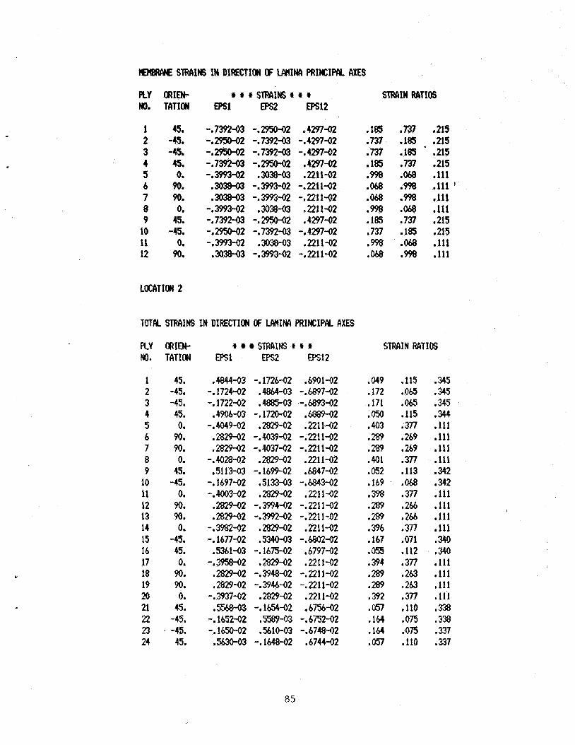
?€M##t€ STRPLINS IN DIRECTION CF WIIW PRINCIM AXES
Y
PLY m).
1 2 3 4 5 6 7 8 9
10 11 12
ORIEN- TATION
45. -45. -45. 45. 0. 90. 90. 0.
45. -45.
0. w.
-.7392-03 -.2950-02 -.2950-02 -.7352-03 -,2950+2 -.7392* -0739263 -.295Mn -*3993-02 .m* .303#3 -.3993-02 .303#3 -.m-02
-.3993-02 ,303-03 -e739243 -.2950-02 -.2950-02 -.7392-03 -.3993-02 ,3038-03 .3038-03 -.ma
,429742 -. 4297-02 -. 4297-02 .4247-02 ,2211-02
-* 221 1-02 -. 221 1-02 .2211-a2 ,4297-02
-* 4297-02 L 221 1-02
-,2211-02
LOCCITION 2
TOTAL sTRcIINs IN DIRECTION OF LMIM PRIHCIPCY AXES
FLY No.
1 2 3 4 5 6 7 8 9
10 11 12 13 14 15 16 17 18 19 20 21 22 23 24
CRIEN- TATIOEI
45. -45. -45. 45. 0.
90. 90. 0.
45. -45.
0. 90. 90. 0.
-45. 45. 0.
90. 90. 0.
45. -45.
' -45. 45.
* STRAINS i. * * EPS1 Eps.2 W l 2
,4844-03 -. 1726-02 ,6901-02 -.1724-02 ,4864-03 -.6897-02 -.1722-02 . e 0 3 -.6893-02
.4906-03 -.1720-02 ,6889-02 -.4049-Q2 .2829-02 .2211-02
.282942 -.#39-02 -.2211-02 ,282942 -.403762 -.2211-02
-.402842 ,282942 .2211-02 51 13-03 -. 1699-02 .6847-02 -. 1697-02 ,513343 -.6843-02
-.4003-02 ,2829-02 ,221142 ,2829-02 -.3?94-02 -.2211-02 .2829-02 -392-02 -.2211-02 -.3?%2-02 .m-02 .2211-02 -.167742 ,5340-03 -.6802-02
,5361-03 -.1675-02 .6797-02 -.3958-02 ,2829-02 '2211-02
,282942 - e 3 9 4 8 4 2 -.2211-02 ,282942 -. 3946-02 -. 221 1-02 -.3937-02 .2829-02 ,2211-02 .556&03 -.16541)2 .6756-02
-.1652-02 ,558943 -.675242 -. 1650-02 .5610-03 -.6748-02 ,5630-03 -.1M-02 ,674442
STRAIN RMIOS
,185 ,737 ,215 ,737 -185 ,215 ,737 .la ,215 .185 ,737 .215 ,998 .ob8 ,111 ,068 ,998 ,111 ' ,068 .598 ,111 .998 ,068 ,111 .185 ,737 ,215 ,737 ,185 ,215 ,998 .068 ,111 ,068 ,998 ,111
STRAIN RATIOS
,049 ,115 3 5 .172 ,065 ,345 ,171 ,065 ,345 ,050 .115 ,344 .403 ,377 ,111 ,289 ,269 ,111 ,289 ,269 ,111 ,401 .377 .ill ,052 ,113 .342 .169 .06% ,342 .a% ,377 .111 ,289 ,266 .ill .m .2M ,111 .396 ,377 ,111 ,167 ,071 ,340 ,055 .112 ,340 ,394 .377 .111 ,289 ,263 ,111 .289 "263 ,111 .392 ,377 ,111 .m ,110 ,338 .I54 ,075 ,338 .1M ,075 ,337 .os7 ,110 ,337
85
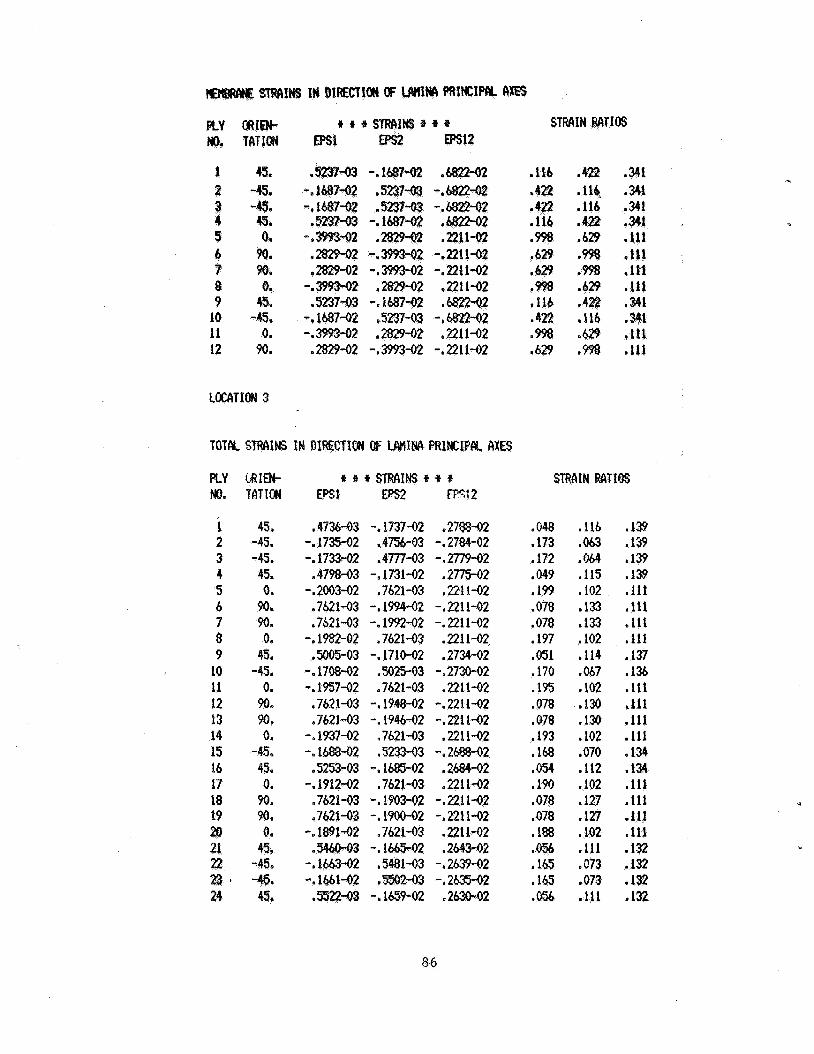
1 45. 2 -45. 3 -43. 4 45, 5 0. 4 w. T Po. 8 0. 9 4%
10 -45. 11 0. 12 90.
STRCIIN RATIOS
.116 ,922 .341 * ,116 ,341 . * 341 . ,34921 ,998 * . e I ,111 I -111
.116 . 1
.42$ ,!lb ,341
.m .629 .la$ &29 *m .ti1
P
PLY C&IW * t * STRAINS * * * STRAIN RATIOS M). TATION mt Eps2 m: 2
1 2 3 4 5 b 7 8 9
I 10 11 12 13 14 15 14 17 18 19 a 21 22 2 3 1 24
45. -45. -45. 45. 0.
90. 90. 0.
45. -45. 0, 90. 90. 0.
-45. 45. 0, 90. w. 0.
45. 745. -4% 4%
.47%43 -. 1737-02 .27@-02 -. 1735-02 ,4756-03 -. 2784-02 -. 1733-02 .4777-03 -.2779-02
.4798-03 -. 1731-02 .2775co2 -.2003-02 ,7621-03 ,2211-02 ,762143 -.1994-02 -.2211-02 ,7621-03 -. 1?92-02 -v2211-02
-.1982-02 ,7621-03 ,2211-02 .5#5-03 -.171M)2 ,2734-02
-.1708-02 ,5025-03 -.2730-02 -.1951-02 .7621-03 .2211-02 .7621-03 -.194862 -.2211-02 .7621-03 -. 1946-02 -.2211-02 -.I93762 .7621-03 ,221142 -.1688782 I)
,5253-03 -. -.I91242 ,762143 ,2211-02
e 762 -I 1903-02 -. 221 1-02 a 762 -. l m 2 -,221142
-.1891-02 ,7621-03 .221L-02 -.1665-02 .2#3-02
,5522-03 - . l a942 .2631)-02
,048 .116 ,139 ,173 ,063 .139 ,172 ,044 ,139 .a49 ,115 ,139
,073 ,133 ,111 ,078 .133 ,111 ,197 ,102 ,111 ,051 ,114 ,137 .I70 ,067 ,136 ,135 ,102 .111 ,078 .13Q .Ell ,078 . 1 3 .111 ,193 ,102 .111 ,168 .070 .134 .054 ,112 ,134 ,190 ,102 ,111 ,078 .127 ,111
,127 .111 ,188 ,102 .111 ,056 ,111 . 1 8 ,165 ,073 ,132 ,165 ,073 .132 .m ,111 ,132
.i9p ,102 . i ir
86
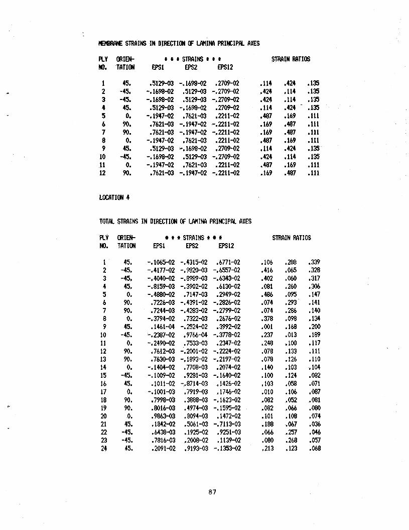
c
E?@lWE STRIIIHS IN DIFECTICW GF WIIM PRINCIPCY AXES
FLY ORID). t t t STWIINS t I) t STRAIN MTIOS We TATION a)s1 Epsz EPs12
1 45. 2 -45. 3 -45. 4 49. 5 0. 6 90. 7 90. 8 0. 9 45. 10 -45. 11 Om 12 90.
.5129-03 -.1698-02 .no942 -. 1698-02 ,512943 -.2709-02 -. 1698-02 ,5129-03 -. 2709-02
.51291)3 -.1698-02 ,270942 -.1947-02 .7621-03 ,221142 ,7621-03 -.1947-02 -.2211-02 .7621-03 -.1947-02 -.2211-02 -.1947-02 .7621-03 .2211-02 .512+03 -.1698-02 .270942
-.1947-02 ,7621-03 ,2211-02 .7621-03 -. 1947-02 -.2211-02 -e169842 e512943 -e270942
.114 .424 ,135 ,424 .114 -135 ,424 ,114 ,135 .114 .424 - .135 .487 ,169 ,111 -169 a 4 8 7 e 1 1 1 -169 a 4 8 7 e 1 1 1 -487 a169 e 1 1 1 ,114 ,424 .135 .424 ,114 ,135 .487 .169 .lll ,169 .487 .lll
LUXTION 4
TOTAL STRAINS IN DIRECTION OF WINA PRINCIPAL AXES
PLY ORIEN- t t STRAINS t STRAIN RCITIOS NO. TATION EPSl EP?2 EPsl2
1 45. 2 -45. 3 -45. 4 45. 5 0. 6 90. 7 90. 8 0. 9 45. 10 -45. 11 0. 12 90. 13 90. 14 0. 15 -45. 16 45. 17 0. 18 90. 19 90. 20 0. 21 45. 22 -4s. 23 -45. 24 45.
-.1065-02 -.431W .6771-02 -.4177-02 -.9820-03 -.6557-02 -.4040-02 -.8989-03 -.6343-02 -. 815943 -. 3902-02 .613O-O2 -.4880-02 ,7147-03 .2949-02 .7226-03 -.4391-02 -.2826-02 ,7244-03 -. 4283-02 -. 2799-02 -. 3794-02 ,732263 .2676-02 ,1461-04 -.2524-02 ,399242 - ,2387-02 .97b6-04 -. 3778-02 -.2490-02 ,7533-03 ,2347-02 -7612-03 -.2001-02 -.2224-02 .7630-03 -. 1893-02 -.2197-02 -.1009-02 .9281-03 -.lblM)2 1011-02 -.871443 ,142642 -. 1001-03 ,7919-03 ,174642 .7998-03 .=-03 -.1623-02 .8016-03 ,4974-03 -. 1595-02 .9%63-43 ,8094-03 ,147242 .1842-02 .5061-03 -.7113-03 .6438-03 .1925-02 .923-03 ,781643 .200&02 .1139-02 .2091-02 ,919343 -.1353-02
-.1404-02 ,770843 .2074-02
,106 .288 ,339 ,416 ,065 .328 .402 ,060 ,317 ,081 ,260 ,306 ,486 ,095 .I47 ,074 .293 ,141 ,074 ,286 ,140 .378 ,098 .134 ,001 ,168 ,200 ,237 ,013 -189 ,248 ,100 ,117 ,078 ,133 ,111 ,078 .126 ,110 ,140 ,103 ,104 ,100 ,124 .082 ,103 ,058 ,071 ,010 .lo6 ,087 A82 .OS2 .081 .082 ,066 ,080 ,101 ,108 .074 ,188 .067 ,036 ,066 .257 ,046 .080 .268 .057 ,213 ,123 .W
87

P -
31
3 -
PLY MI. 12 IS CRITI No. 2 ~ I ~ A T I ~ = BB.
TOTAL STRAINS IN DIRECTION W LAIIIM PRINCIPAL AXES
PLY ORIEN- .) ii * STRAINS * * * STRAIN RATIOS NO. TATION Eplsl Eps2 EPsl2
1 2 3 4 5 6 7 8 9
10 11 12
90. 45.
-45. 0.
90. 0. 0. 90. 0.
-45. 45. 90.
,5604-03 -. 1003-02 -. 1001-02 - e m 4 2 .5604-03
- . E r n 2 -.2513-02 . W - Q 3 -. 2 4 M
-.9577-03 -.95%-03
,5604-03
-. 2571-02 - . lMJ3-02 -1 1001-02
* 5604-03 -. 2534-0.2 .w* ,5604-03
-I TsLM-f)2 . m 4 3 -. 9517-03 -. 9556-03
- .2467-02
* 3795-09 ,3127-02
-.3123-02 .oooo * 373Q-W *m .oooo ,3715-09 .m -.3035-02 .3032-02 .3670-09
,171 .#67 .Ob7 075
,169 ,075 .OB * lb? ,075 e 064 .w ,164
.ooo 156
.156
.ooo
.ooo
.QQQ
.ooo
.009
.O00 ,152 ,152 .ooo
88
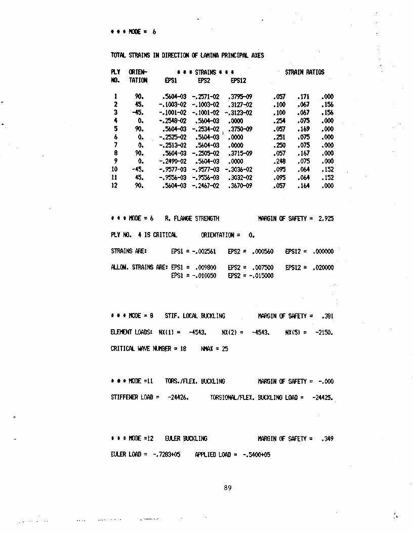
a
1 90. 2 6. 3 -45. 4 0. 5 90. 6 0. 7 0. 8 90. 9 0.
10 -45, 11 45. 12 90.
.5604-03 -.m1-02 ,3795-09 -. 1003-02 -. 1003-02 .3127-Q2 -. 1001-02 -. 1001-02 -.312342 -.m8-02 .W-a .m
-*25m2 ,5604-03 .oooo -.25/3-02 .5609-03 .oooo ,560443 -.2505-02 .371509 -.249M)2 .%04-03 .oooO -a951743 -.9577-03 -.3034-02 -.9556-03 -.9556-03 .3032-02 .5604-03 -.2467-02 ,3670-09
,5604-03 -.m-02) 93750-09
,051 .17i .OOO '100 .(M7 .156 ,100 .ob7 .156 ,254 ,075 .Ooo ,057 -169 .OOO .251 ,075 .OOO .250 ,075 .OOo .On ,167 .OOO .248 ,075 .Ooo ,095 .OM ,152 ,095 .OM .152 ,057 ,144 .OOo
+ * * H O i E = b R.RW;ESTWNGM M I N O F S C Y r P l = 2.925
PLY NO. 4 IS CRITICRL CRIENTATION = 0.
m1NS NE: EPsl=-.oo2561 m = ,000560 EPsl2= ,000rJ00
* * HOE =11 TORS./REX. BUCKLING M I N OF WETY = -.#O
S T I F F E E R Low) = -24426. TORSIONCY1FLEX. BlwmtING LOAD = -24425.
* * * rot€ =I2 NLER BwmLING EWRGIN#FSC\FRY= ,349
E u € R L o l u f = -.7283+05 wpLIEDLo(sD= -,s4ootO5
89
I ._- .̂._ - .... . . ~ . _. . . .. ... . . .

513 EKK5NtSTIF. I
TMXY = ,208603
X @ .#o
Y = .337 Y = .375 Y = .412 Y = ,450 Y = .487 Y = ,523 Y = ,562 Y = .m Y = .a7 Y = .bf5 'i! 3 .712 Y = .m x = lO.Oo0
Y E 'OIX) Y = ,037 Y = ,075 Y = ,112 Y - ,150 Y = ,187 Y E .m Y = .262 Y = ,300 Y = .a7 Y = ,375 Y = ,412
. *
8
.593tQ3
.768+03 ,103.tM m 14*63 .2l4* .331* .w* .872to4 .146+05 .248+05
TMXZ
.ooo -. 152-06 -.593-06 -. 1 5 0 4 - * - - -I 74345 -.904-05 -. 110-04 -. 1354% -. 171-04
-.714.-03
TAUYZ
-. m+03 -. 199+02 .6i?&O3 1 4 W
.1
.M3* 1aO+M
.1
.1
.1#W
90
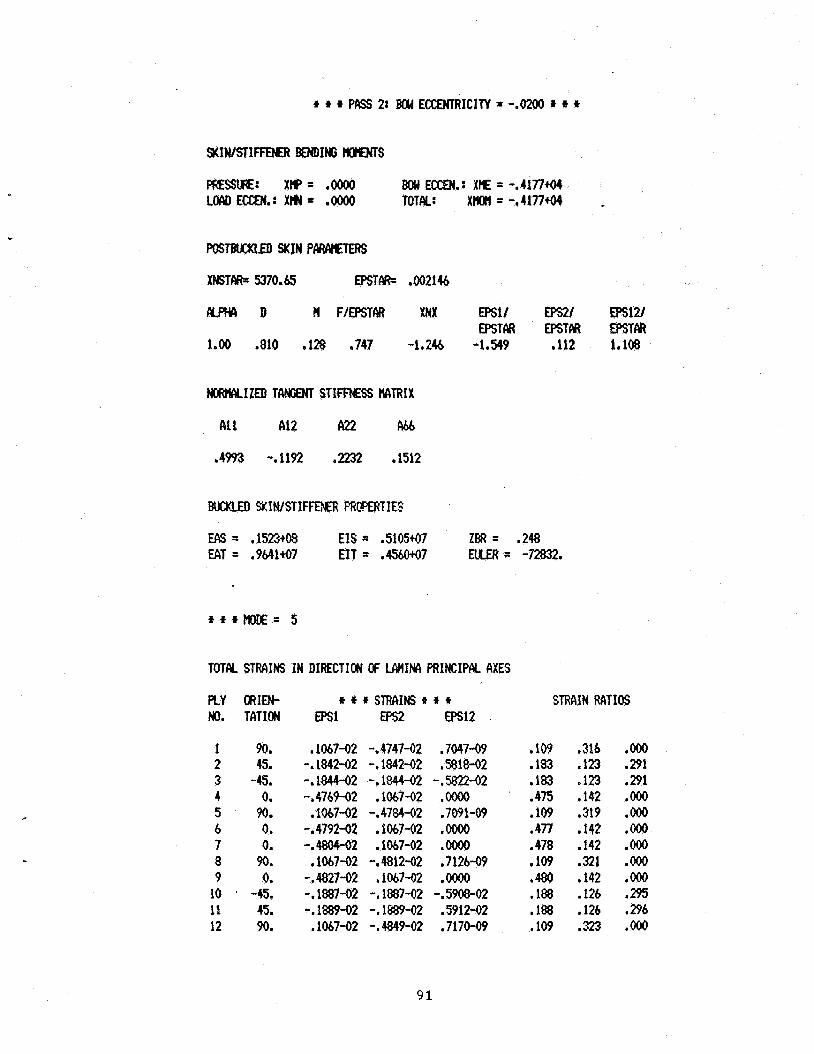
Y
SxIWsrIFFpER BENDING m s
W s m SKIN PMWTEflS
W T & 5370.65 D)STW- ,002146
A L P H A D H F /MM XNX 8s1/ EpSz/ m12/ EPSTM EPSTW EPSTM
1.00 .810 ,128 .747 -1.24 -1.549 ,112 1.108
NMUMLIZED TANGEM S T I M S S MTRIX
-4993 -.1192 ,2232 -1512
EA5 = .1523t08 EIS = .5105+07 lBR= ,248 EAT= .9&41+07 E I T = . 4 W 7 EuLER= -72832.
TOTAL STRAINS IN DIRECTION OF M I M PRINCIPAL AXES
PLY HD.
1 2 3 4 5 6 7 8 9
10 11 12
ORIW t f f STRIIIF(S f f + STRAIN RATIOS TATION EPSl EPs2 EPsl2
90. 45.
-45. 0. 90. 0. 0. 90. 0.
-45. 45. 90.
.1067-02 -. 4747-42 -. 184242 -. 1842-02 -.1844-02 -.1844-02 -.4769-02 .lo6742 ,106742 - ,4784-02 -.4792-02 ,1067-02 -.4804-02 .1067m ,1067-02 -. 481262 -.a2742 ,1067-92 -.1887-02 -.1#7-02 -.1889-02 -.1889-02 ,1067-02 -. 484942
,7047-09 .5818-02 -. 5822-02 .oooo .7091-09 .m .oooo ,7126-09 .oooo -. 5908-02 .5912-02 7170-09
,109 ,316 .Ooo ,183 ,123 ,291 ,183 ,123 ,291 ,475 ,142 .OOO ,109 ,319 .OOO ,477 .142 .OOO .478 .142 .OOO ,109 ,321 .OOo .4&0 ,142 .OOO .1# ,126 ,295 .188 ,126 .296 ,109 ,323 .ooo
91
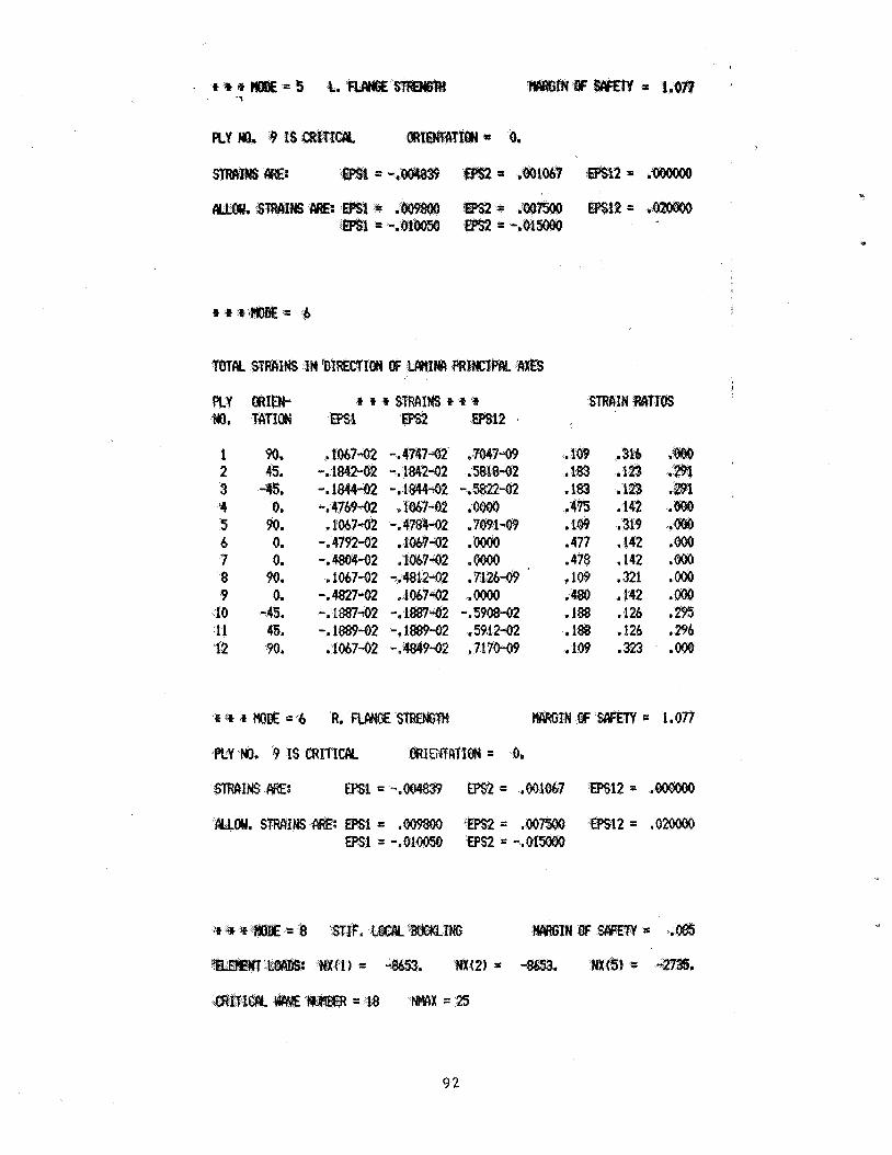
. * * + = 5 t. ff’m = 1.m ’ ‘1
1 90. 2 45. 3 45. 14 0. 5 90. 6 0. 7 0. 8 90. 9 0,
10 -45. 11 45. l2 9090.
,109 ,183 .1%3 . 4 E .lo9 .477 ,478 v 109 ,1180 . I%% 1893
.1#
123
.om ,142 .OM ,142 .ooO ,321 .ooo .M2 .m ,626 ,295 .126 .ab .323 .Ooo
ow. sTFW4.s ARE: - - mi2 = .om 1 = -,OloOfjo eS2 = -.
c
9 2
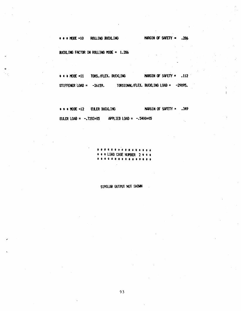
+ t t m =10 m1NG BUCKLING W I N O F S l Y E T Y = ,286
W I N G FACT(# IN ROUING #E = 1.286
t t 4 NILE 4 1 TORS./FLEX. BUCKLING W I N OF SIYEM = ,112
STIFFDER LOAD = -26159. T O R S I W I F L E X . BUCKLING LOAD = -29095. !
i t t * t * Y ' C * i il t 9 * t * ***LLOADCASEtmgER 2 * * t t t * * t t * t t t t * t i t *
SIMILAR WTWT NOT StYlwN
9 3
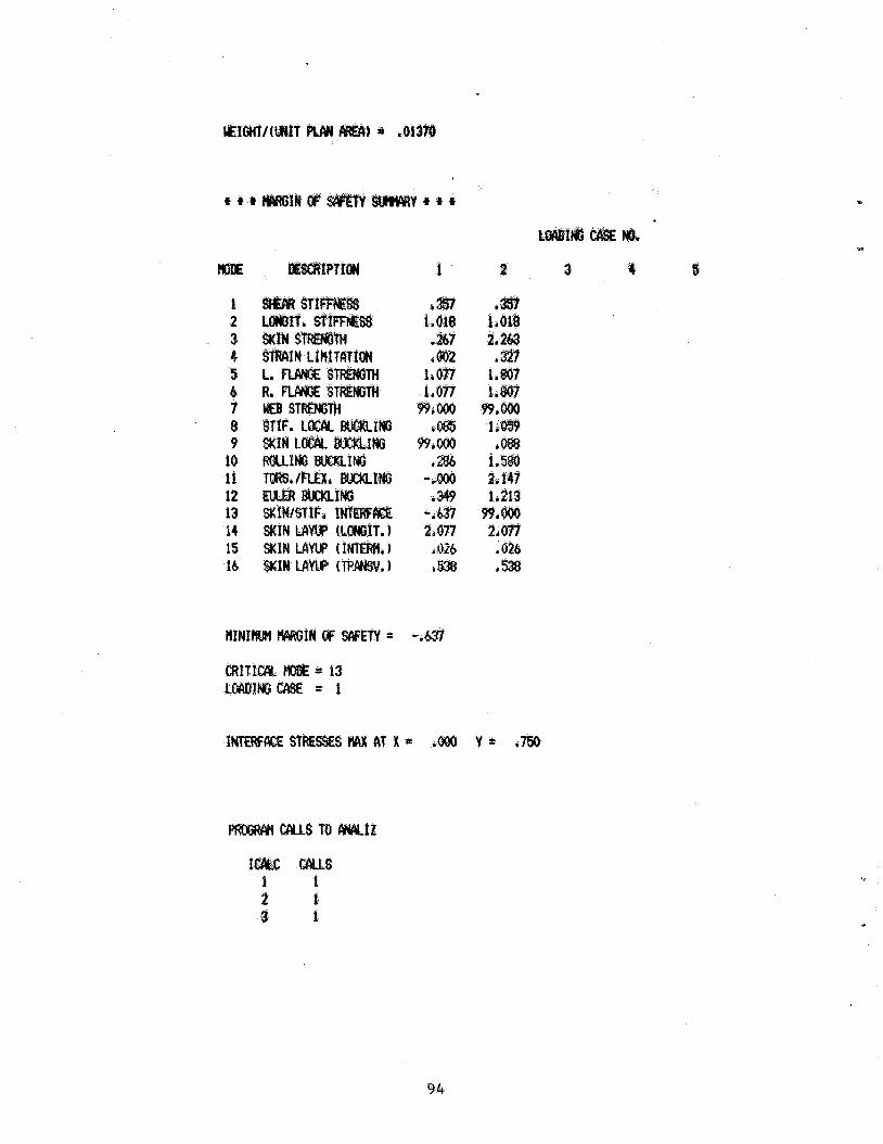
1 2 3 4 5 6 7 8 9
10 11 12 13 14 15 lb
CRITICPY, = 13 1 ~ 1 ~ ~ = 1
tw CAUS I 1 2 f 0 1
94
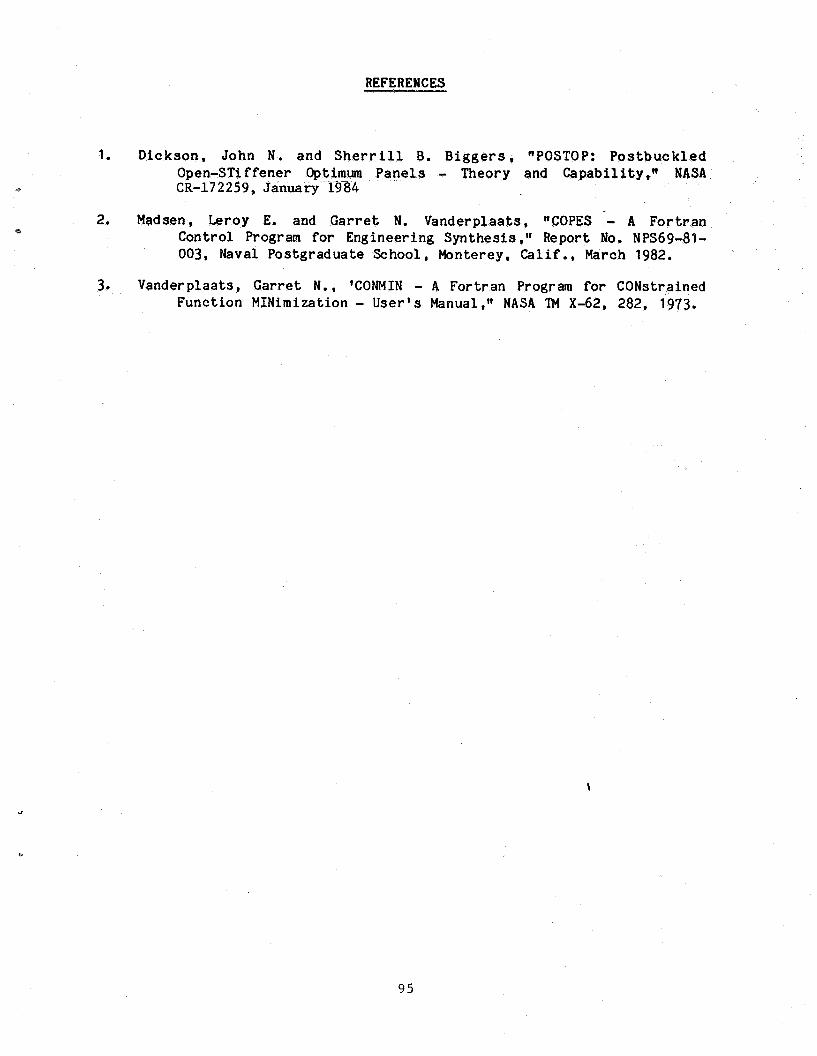
REFERENCES
1. Dickson, John N . and S h e r r i l l B. B i g g e r s , "POSTOP: P o s t b u c k l e d Open-STiffener Optimum Panels - Theory and Capabi l i ty ," NASA
1GI CR-17 2 2 5 9, January 1984
2. Madsen, Leroy E. and Garret N. Vanderplaats, "COPES - A For t ran Control Program f o r Engineering Synthesis Report No. NPS69-81- 003, Naval Postgraduate School, Monterey, Calif., March 1982.
3. Vanderplaats, Garret N . , 'CONMIN - A Fortran Program fo r CONstrained Function MINimization - User 's Manual," NASA 'XI4 X-62, 282, 1973.
\
9 5
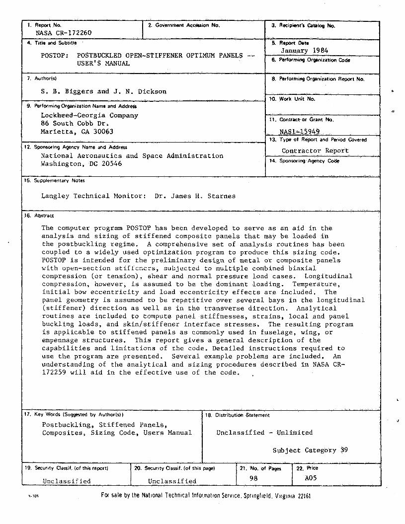
6. Performing Organization Coda POSTOP: POSTBUCIUED OPEN-STIFFENER OPTIMLJM P
USER'S MANUAL
S. B. Biggers and J . N . Dickson
Lockheed-Georgia Company I 86 South Cobb D r . 11. Contractor Grant No.
Washington, DC 20546
Langley Technica l Monitor: D r . James H. S t a r n e s
16. Abstract
The computer program POSTOP h a s been developed t o s e r v e as an a i d i n t h e a n a l y s i s and s i z i n g of s t i f f e n e d composite panels t h a t may b e loaded i n t h e pos tbuckl ing regime. A comprehensive set of a n a l y s i s r o u t i n e s h a s been coupled t o a wide ly used o p t i m i z a t i o n program t o produce t h i s s i z i n g code. POSTOP i s in tended f o r t h e p re l imina ry d e s i g n of m e t a l o r composite p a n e l s K i t h open-sect ion s t i f i c r i c r s , sub jec t ed to m u l t i p l e combined b i a x i a l compression (o r t e n s i o n ) , shea r and normal p r e s s u r e load c a s e s . Longi tudina l compression, however, is assumed t o b e t h e dominant l oad ing . Temperature, i n i t i a l bow e c c e n t r i c i t y and load e c c e n t r i c i t y e f f e c t s are inc luded . The panel geometry i s assumed t o be r e p e t i t i v e ove r several bays i n t h e l o n g i t u d i n a l ( s t i f f e n e r ) d i r e c t i o n as w e l l as i n t h e t r a n s v e r s e d i r e c t i o n . A n a l y t i c a l r o u t i n e s are inc luded t o compute pane l s t i f f n e s s e s , s t r a i n s , l o c a l and pane l buckl ing loads , and s k i n l s t i f f e n e r i n t e r f a c e stresses. The r e s u l t i n g program is a p p l i c a b l e t o s t i f f e n e d p a n e l s as commonly used i n f u s e l a g e , wing, o r empennage s t r u c t u r e s . T h i s r e p o r t g i v e s a g e n e r a l d e s c r i p t i o n of t h e c a p a b i l i t i e s and l i m i t a t i o n s of t h e code. Deta i led i n s t r u c t i o n s r equ i r ed t o u s e t h e program are p resen ted . S e v e r a l example problems are included. An unders tanding of t h e a n a l y t i c a l and s i z i n g procedures desc r ibed i n NASA CR- 172259 w i l l a i d i n t h e e f f e c t i v e use o f t h e code. I
. I I
18. Distribution Statement
Unclas s i f i ed - Unlimited
Sub jec t Category 39
19. Security Classif. (of this report) 20. Security Classif. (of tht5
I I Linclassif i ed 98 A05 Unc l ass i f ied
Y- 305 For sale by the Natlonal Technical Information Service. Springfield. Virginra 22161
*
a
L
J


![Cardiac Surgery PostOp ICU [1862] - it.houstonmethodist.org](https://img.pdfslide.us/doc/110x75/61bd422561276e740b10f7fd/cardiac-surgery-postop-icu-1862-it-.jpg)