Embed Size (px)
Citation preview

Energetic Copper Coating on Stainless Steel
Power Coupler for SRF Application
Irfan Irfan, Steve Chapman, Mahadevan Krishnan, Katherine Velas Alameda Applied Sciences Corporation (AASC), San Leandro, California 94577
Walid Kaabi LAL, 91898 Orsay Cedex France
This research is supported at AASC by DOE SBIR Grant: DE-SC0009581
Poster ID: 2131
Motivation:
Stainless steel power coupler parts are required to be coated
with 10 to 30 µm copper film.
Conventional electroplating method has two drawbacks:
:- Inadequate adhesion strength
:- A thin flash layer of Ni (magnetic) film
AASC has developed an energetic coating process (CED)
We demonstrate the potential of the CED process in Cu
coating on power couplers.
Ref: H. Weise, “How to Produce.. ,” WEIB03, Proc. IPAC, Dresden, Germany (2014).
Ref: L. Popielarski et al., “Testing of Copper Plating..,” THP067, Proc. SRF, Paris, France (2013).
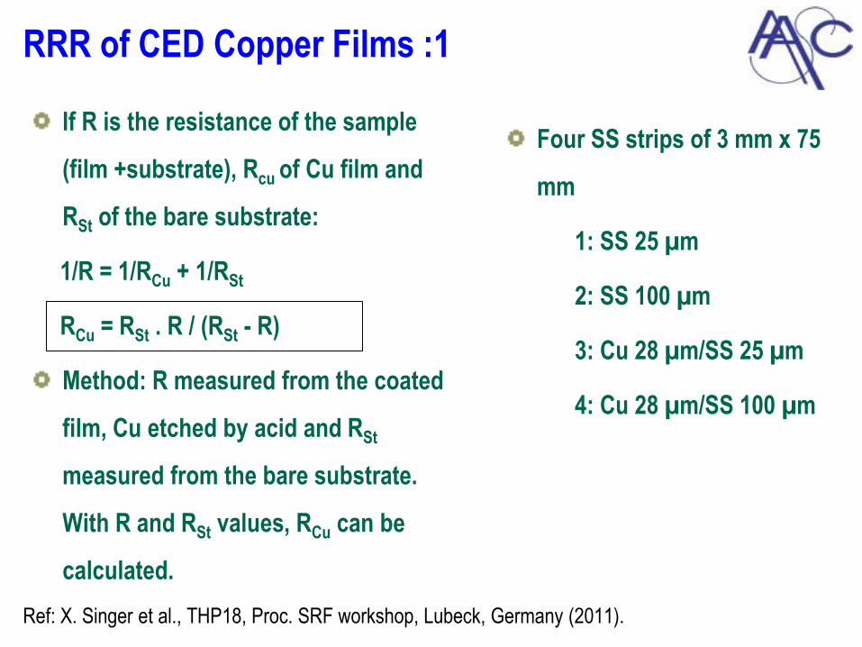
RRR of CED Copper Films :1
Four SS strips of 3 mm x 75
mm
1: SS 25 µm
2: SS 100 µm
3: Cu 28 µm/SS 25 µm
4: Cu 28 µm/SS 100 µm
Ref: X. Singer et al., THP18, Proc. SRF workshop, Lubeck, Germany (2011).
If R is the resistance of the sample
(film +substrate), Rcu of Cu film and
RSt of the bare substrate:
1/R = 1/RCu + 1/RSt
RCu = RSt . R / (RSt - R)
Method: R measured from the coated
film, Cu etched by acid and RSt
measured from the bare substrate.
With R and RSt values, RCu can be
calculated.
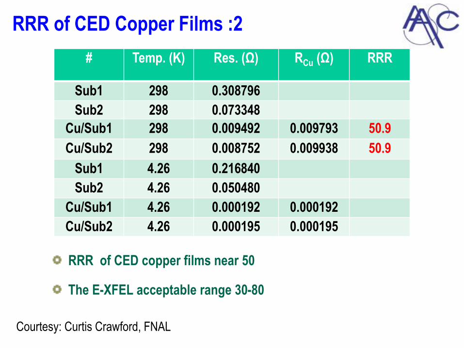
RRR of CED Copper Films :2
RRR of CED copper films near 50
The E-XFEL acceptable range 30-80
Courtesy: Curtis Crawford, FNAL
# Temp. (K) Res. (Ω) RCu (Ω) RRR
Sub1 298 0.308796
Sub2 298 0.073348
Cu/Sub1 298 0.009492 0.009793 50.9
Cu/Sub2 298 0.008752 0.009938 50.9
Sub1 4.26 0.216840
Sub2 4.26 0.050480
Cu/Sub1 4.26 0.000192 0.000192
Cu/Sub2 4.26 0.000195 0.000195

Adhesion Tests on CED Copper Films :1
Tube 3” ID, 7” long Stainless Steel
304L from Lesker.
Wiped with TCE, acetone, IPA
Coated with a 50 µm Cu film at
300 ºC
Blasted with 1250 psi high purity
water
No deleterious effects of HPWR
test found on the coating.
Courtesy : Curtis Crawford, FNAL
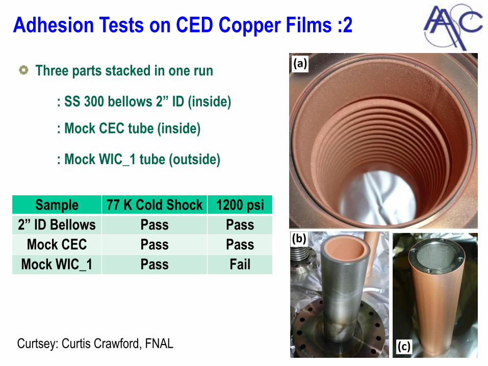
Adhesion Tests on CED Copper Films :2
Three parts stacked in one run
: SS 300 bellows 2” ID (inside)
: Mock CEC tube (inside)
: Mock WIC_1 tube (outside)
Sample 77 K Cold Shock 1200 psi
2” ID Bellows Pass Pass
Mock CEC Pass Pass
Mock WIC_1 Pass Fail
Curtsey: Curtis Crawford, FNAL
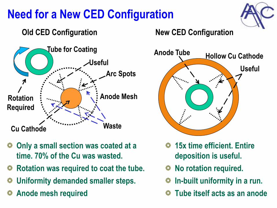
Need for a New CED Configuration
Only a small section was coated at a
time. 70% of the Cu was wasted.
Rotation was required to coat the tube.
Uniformity demanded smaller steps.
Anode mesh required
Useful
Old CED Configuration
Waste
New CED Configuration
Useful
Hollow Cu Cathode
Cu Cathode
Tube for Coating Anode Tube
Rotation
Required
Arc Spots
Anode Mesh
15x time efficient. Entire
deposition is useful.
No rotation required.
In-built uniformity in a run.
Tube itself acts as an anode

Test of the New CED Configuration
Large hollow cathode
surrounding a central
anode.
Arcs induced from inside
Cu cathode coats anode
tube from outside.
Parameters
characterized to
understand the new
configuration.
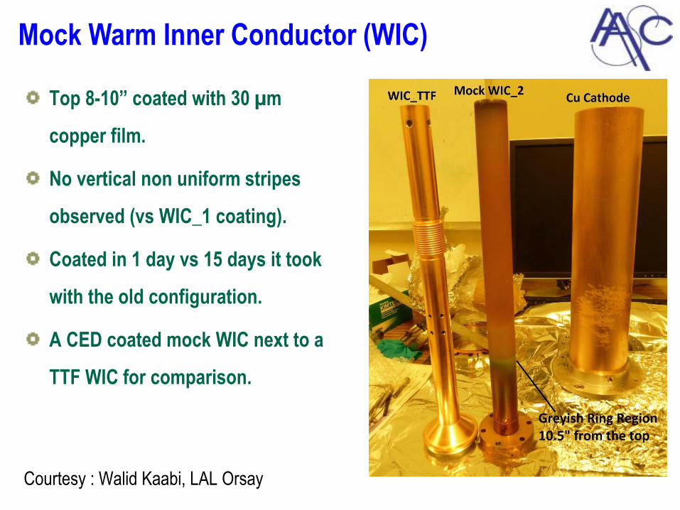
Mock Warm Inner Conductor (WIC)
Top 8-10” coated with 30 µm
copper film.
No vertical non uniform stripes
observed (vs WIC_1 coating).
Coated in 1 day vs 15 days it took
with the old configuration.
A CED coated mock WIC next to a
TTF WIC for comparison.
Courtesy : Walid Kaabi, LAL Orsay
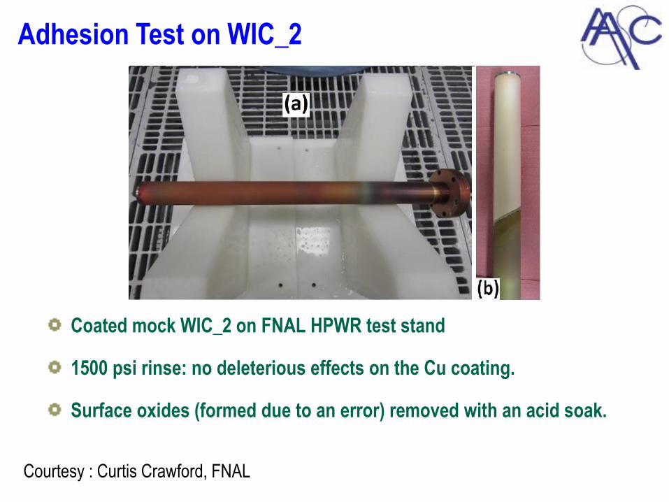
Adhesion Test on WIC_2
Coated mock WIC_2 on FNAL HPWR test stand
1500 psi rinse: no deleterious effects on the Cu coating.
Surface oxides (formed due to an error) removed with an acid soak.
Courtesy : Curtis Crawford, FNAL
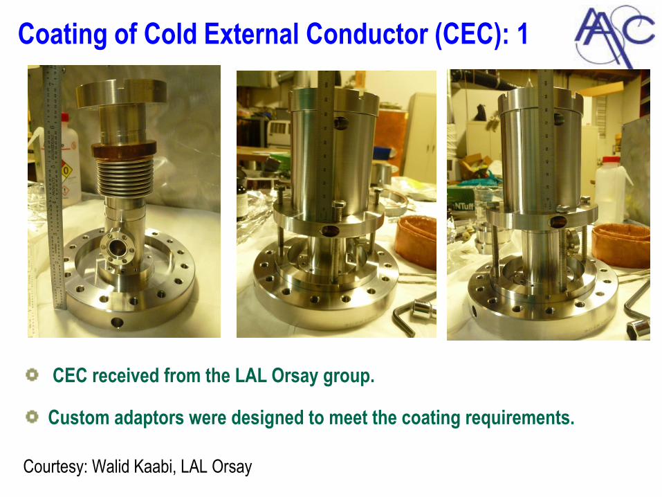
Coating of Cold External Conductor (CEC): 1
CEC received from the LAL Orsay group.
Custom adaptors were designed to meet the coating requirements.
Courtesy: Walid Kaabi, LAL Orsay
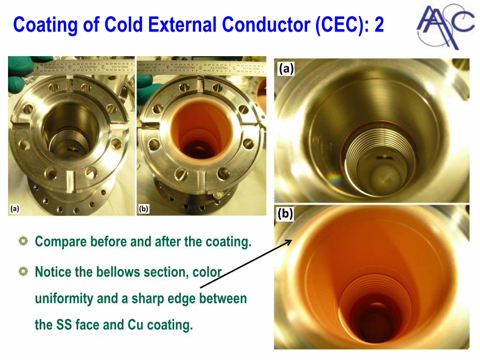
Coating of Cold External Conductor (CEC): 2
Compare before and after the coating.
Notice the bellows section, color
uniformity and a sharp edge between
the SS face and Cu coating.
Conclusions:
Paper ID THPB083
RRR Value of CED copper films: 50 (meets requirement)
Demonstrated adhesion strength:
:- 1250-1500 psi with HPWR tests
:- 77 Kelvin cold shock tests
Demonstrated a robust coating on a mock coupler part.
Successfully coated a TTF cold external conductor part.
Ready to coat other power coupler parts for RF tests.