Embed Size (px)
Citation preview

PNNL-13900
Post-Retrieval and Pre-Closure High-Level Radioactive Liquid Waste Tank Lay-up Strategies Part ll Implementation Plan M. Elmore C. Henderson* May 15, 2001 *Jacobs Engineering Group, Inc. Prepared for the U.S. Department of Energy under Contract DE-AC06-76RL01830
DISCLAIMER This report was prepared as an account of work sponsored by an agency of the United States Government. Neither the United States Government nor any agency thereof, nor Battelle Memorial Institute, nor any of their employees, makes any warranty, express or implied, or assumes any legal liability or responsibility for the accuracy, completeness, or usefulness of any information, apparatus, product, or process disclosed, or represents that its use would not infringe privately owned rights. Reference herein to any specific commercial product, process, or service by trade name, trademark, manufacturer, or otherwise does not necessarily constitute or imply its endorsement, recommendation, or favoring by the United States Government or any agency thereof, or Battelle Memorial Institute. The views and opinions of authors expressed herein do not necessarily state or reflect those of the United States Government or any agency thereof. PACIFIC NORTHWEST NATIONAL LABORATORY operated by BATTELLE for the UNITED STATES DEPARTMENT OF ENERGY under Contract DE-AC06-76RL01830 Printed in the United States of America Available to DOE and DOE contractors from the Office of Scientific and Technical Information, P.O. Box 62, Oak Ridge, TN 37831-0062; ph: (865) 576-8401 fax: (865) 576-5728 email: [email protected] Available to the public from the National Technical Information Service, U.S. Department of Commerce, 5285 Port Royal Rd., Springfield, VA 22161 ph: (800) 553-6847 fax: (703) 605-6900 email: [email protected] online ordering: http://www.ntis.gov/ordering.htm
This document was printed on recycled paper.
(8/00)
PNNL-13900
Post-Retrieval and Pre-Closure High-Level Radioactive Liquid Waste Tank Lay-up Strategies — Part II Implementation Plan
May 15, 2001 Prepared for Tanks Focus Area and the U.S. Department of Energy under Contract DE-AC06-76RL01830 Jacobs Engineering Group, Inc., and Pacific Northwest National Laboratory Richland, Washington 99352
01-005-0515 ii May 15, 2001
CONTENTS
1.0 INTRODUCTION .............................................................................................................. 1
2.0 NEED FOR TANK LAY-UP STRATEGIES .................................................................... 1 2.1 TANKS FOCUS AREA WORKSHOP.................................................................. 2 2.2 HANFORD WORKSHOP...................................................................................... 4
3.0 EVALUATION METHODOLOGY .................................................................................. 4
4.0 EVALUATION CRITERIA ............................................................................................... 5
5.0 BACKGROUND ................................................................................................................ 7
6.0 DOE TANK AND WASTE INFORMATION SUMMARY ............................................. 7
7.0 SITE-SPECIFIC DESCRIPTIONS .................................................................................... 9 7.1 HANFORD SITE.................................................................................................... 9
7.1.1 Single-Shell Tanks .................................................................................... 10 7.1.2 Hanford Double-Shell Tanks .................................................................... 11 7.1.3 Path to Closure for the Hanford Site......................................................... 11 7.1.4 Regulatory Drivers for the Hanford Site................................................... 12 7.1.5 Milestones for the Hanford Site................................................................ 13 7.1.6 Post-Retrieval Tank Waste Characterization ............................................ 13
7.2 SAVANNAH RIVER SITE.................................................................................. 13 7.2.1 Storage Tanks at the Savannah River Site ................................................ 14 7.2.2 Savannah River Site High-Level Waste Treatment and Tank Closure..... 17 7.2.3 Path to Closure for the Savannah River Site............................................. 17 7.2.4 Regulatory Drivers for the Savannah River Site....................................... 18 7.2.5 Milestones for the Savannah River Site.................................................... 19
7.3 IDAHO NATIONAL ENGINEERING AND ENVIRONMENTAL LABORATORY ................................................................................................... 19 7.3.1 Characteristics of Idaho National Engineering and Environmental
Laboratory Tank Waste............................................................................. 20 7.3.2 Storage Tanks and Calcine Bin Sets at the Idaho National Engineering
and Environmental Laboratory ................................................................. 21 7.3.3 Path to Closure for the Idaho National Engineering and Environmental
Laboratory................................................................................................. 23 7.3.4 Regulatory Drivers for the Idaho National Engineering and
Environmental Laboratory........................................................................ 23 7.3.5 Milestones for the Idaho National Engineering and Environmental
Laboratory................................................................................................. 24 7.4 OAK RIDGE RESERVATION............................................................................ 24
7.4.1 Legacy Waste............................................................................................ 25 7.4.2 Newly Generated Waste ........................................................................... 25 7.4.3 Tank Design .............................................................................................. 26 7.4.4 Path to Closure for the Oak Ridge Reservation ........................................ 28
01-005-0515 iii May 15, 2001
7.4.5 Regulatory Drivers for the Oak Ridge Reservation.................................. 29 7.4.6 Milestones for the Oak Ridge Reservation ............................................... 29
8.0 PROPOSED WORK PLAN ............................................................................................. 30 8.1 GENERIC HIGH-LEVEL WASTE TANK LAY-UP ALTERNATIVES
EVALUATION METHODOLOGY .................................................................... 30 8.1.1 Target Problem.......................................................................................... 30 8.1.2 Work Element Descriptions...................................................................... 30
9.0 REFERENCES ................................................................................................................. 33
FIGURES
1. Hanford Path to Closure.................................................................................................... 11 2. Savannah River Site Path to Closure ................................................................................ 18 3. Idaho National Engineering and Environmental Laboratory Path to Closure .................. 23 4. Oak Ridge Reservation Path to Closure............................................................................ 28
TABLES
1. Comparison of Tanks at Each Site...................................................................................... 8 2. Hanford Site Milestones ................................................................................................... 13 3. Summary of Storage Tanks at the Savannah River Site ................................................... 16 4. Savannah River Site Milestones ....................................................................................... 19 5. Summary of the Waste Storage Tanks at the Idaho National Engineering and
Environmental Laboratory................................................................................................ 21 6. Idaho National Engineering and Environmental Laboratory Milestones ......................... 24 7. Summary of Waste Storage Tanks at Oak Ridge National Laboratory............................ 28 8. Oak Ridge Reservation Milestones................................................................................... 29

01-005-0515 iv May 15, 2001
LIST OF TERMS
BVESTs Bethel Valley Evaporator Service Tanks DOE U.S. Department of Energy DST double-shell tank DWPF Defense Waste Processing Facility EIS environmental impact statement EPA U.S. Environmental Protection Agency GAAT Gunite and Associated Tanks HLW high-level waste INEEL Idaho National Engineering and Environmental Laboratory INTEC Idaho Nuclear Technology and Engineering Center Jacobs Jacobs Engineering Group Inc. LLW low-level waste MVCITs Melton Valley Capacity Increase Tanks MVSTs Melton Valley Storage Tanks NRC U.S. Nuclear Regulatory Commission ORR Oak Ridge Reservation PNNL Pacific Northwest National Laboratory RCRA Resource Conservation and Recovery Act of 1976 SCDHEC South Carolina Department of Health and Environmental Control SNF spent nuclear fuel SRS Savannah River Site SST single-shell tank TFA Tanks Focus Area TRU transuranic WVDP West Valley Demonstration Project
01-005-0515 1 May 15, 2001
1.0 INTRODUCTION
Jacobs Engineering Group Inc. (Jacobs) is developing and evaluating high-level waste (HLW) tank lay-up strategies in collaboration with the Pacific Northwest National Laboratory (PNNL) and West Valley Nuclear Services Company. This work is included in the U.S. Department of Energy (DOE) Tanks Focus Area (TFA) Technical Task Plan RL30WT21A, “Post-Retrieval and Pre-Closure HLW Tank Lay-Up.”
Jacobs and PNNL are completing the approved portion of TTP RL30WT21A (Part I), Tank Lay-Up Strategies for the West Valley Demonstration Project (WVDP). Lay-up is the period between initial decontamination and decommissioning of the tanks and final closure. Alternative strategies have been identified and decision criteria have been developed to support selection of a preferred strategy for safe lay-up of the WVDP HLW tanks. The lay-up strategies will be evaluated with respect to the decision criteria to provide WVDP with a defensible decision process for selecting a tank lay-up strategy.
This Draft Work Plan for Part II, HLW Tank Lay-Up Strategies for the Entire DOE Complex, is an extension of the work completed to develop a WVDP Tank Lay-Up methodology. The proposed next step is to extend the methodology to address lay-up needs for the other HLW tanks across the DOE complex. This Draft Work Plan includes a discussion of the HLW systems and issues at each site and the approach to identify and evaluate tank lay-up strategies. The proposed approach will provide a technically defensible methodology for evaluating tank lay-up strategies against a number of criteria, such as reducing monitoring and maintenance costs, meeting environmental regulations for tank closure, protecting worker health and safety, and addressing stakeholder concerns.
Completion of this proposed scope of work will benefit all the sites by developing a common, demonstrated methodology for the transition from active storage to closure of the tanks.
This Draft Work Plan will be used by the TFA Technical Integration Manager for Safety to make a determination on a path forward for Part II.
2.0 NEED FOR TANK LAY-UP STRATEGIES
As DOE sites complete retrieval of waste from tanks, it may not be possible to immediately move to final closure of the tank systems. This period of time may be decades for some tanks. Therefore lay-up, defined as placing tanks in a safe, stable, and minimum maintenance mode, needs to be considered on the path to closure. The operating and monitoring requirements during this transition phase will be different than during active waste storage.
All the sites have programs in place to monitor the condition of the tanks to prevent leaks to the environment and have long-range plans for closure of the tanks. However, the selection of preferred alternatives for interim lay-up of tanks has not been rigorously pursued. In addition to the tanks themselves, several of the sites have concerns with piping and other auxiliary equipment associated with the tanks.
01-005-0515 2 May 15, 2001
2.1 TANKS FOCUS AREA WORKSHOP
The TFA held a Tank Integrity Workshop in Atlanta, Georgia, on October 31 and November 1, 2000, to focus on the following issue:
“Our challenge is to ensure continued safe management and operation of the necessary tanks for whatever period of time these tanks are required in completing the weapons complex clean up.”
The workshop participants felt that implementation of DOE Order 435.1 along with its guidance document (Guidelines for Development of Structural Integrity Program for DOE High-Level Waste Storage Tanks) is very important. The fact that the requirements are flexible and not prescriptive was also cited as important. The participants felt that most, if not all, the elements of a good tank integrity program had been considered and implemented somewhere in the DOE complex. The participants noted that communication, both internal and external to the sites, is very valuable and has improved in recent years. However, the participants felt that a change in culture at the sites that promotes the removal of barriers and encourages more openness about problems and lessons learned was equally important. The workshop participants felt that tools for analysis, inspection, and monitoring of the tanks and waste must continue to improve.
While it was recognized by the participants that many site-specific challenges exist, it was felt that consistency among the sites improves the tank structural integrity programs. Consistency allows the sites to learn from and build on each other’s efforts, as well as contribute to a better working relationship with regulators and other stakeholder groups.
The participants viewed TFA funding for integrity assessment activities as a positive step. The enthusiastic direction and support provided by the Safety Technical Integration Manager was specifically mentioned. The sites welcome any assistance provided to assess their options for continued safe operation of tanks.
Even though the focus of this workshop was maintaining integrity for continued operation of tanks, many of the issues identified are also applicable during temporary lay-up. A detailed review and compilation of the options available for temporary lay-up at each site would promote additional sharing of information and options. There may be common solutions to lay-up at several sites that may not be identified without an integrated lay-up evaluation effort for all the sites.
The people involved with tank integrity activities should be valuable resources for the second phase of the tank lay-up task. These people provide a diverse and knowledgeable pool of personnel committed to tank integrity at each site.
Some issues were identified and potential solutions suggested by the participants. Those that are pertinent to tank lay-up are listed below. Many of these solutions will be assessed during the proposed Part II task.
Issue: Networking and communications between headquarters and sites, and across sites, is not adequate to support a collaborative, consistent, and cost-effective tank structural integrity program effort. Sites do not have an incentive to share information with other sites.
01-005-0515 3 May 15, 2001
Proposed solutions:
• Request that the sites identify participants and parties interested in tank structural integrity activities at their site.
• Improve information flow on problems, lessons learned, accomplishments, and other subjects among the sites.
• Hold meetings or workshops to address specific topics/technical issues as needed.
Issue: Technology development required to implement the full scope of the tank structural integrity program may be hampered at some sites because of the unavailability of subject matter experts or lack of management commitment to invest in necessary technology development.
Proposed Solutions:
• Identify subject matter experts at each site.
• Compile a reference database that contains technical topics and contacts.
• Identify sources for compiling lessons learned from other industries.
• Conduct a “state of the complex” review of tank structural integrity program implementation.
• Implement a mechanism to establish and convene a complex-wide design review panel.
• Request the contractors to consider resource sharing (people) to ensure that the new tank structural integrity program implementation is a success.
Issue: Federal and state regulatory requirements are inconsistent and convoluted due to the ambiguity of DOE Order 435.1 and the different regulatory and oversight regimes for each site. DOE has not specified the guidance as the only mechanism to comply with the order. As a result, the resources and ongoing funding commitment by each site are not consistent for implementing the tank structural integrity program.
Proposed Solutions:
• Request DOE to authorize and direct the preparation of a tank structural integrity program panel strawman document that meets DOE Order 435.1 requirements.
• Establish a champion/point of contact at DOE-Headquarters.
• Gain Defense Nuclear Facilities Safety Board support of the champion and organization concept.
01-005-0515 4 May 15, 2001
• Ensure that all sites endorse the new tank structural integrity program requirements.
• Ensure that management is fully aware and informed about compliance issues.
2.2 HANFORD WORKSHOP
CH2M HILL Hanford Group, Inc. held a workshop May 1-4, 2001 to initiate an effort to develop a technical basis for extending the lifetimes of Hanford’s double-shell tanks (DSTs). Included in this workshop were numerous presentations by experts from across the DOE complex in tank waste chemistry, corrosion testing and monitoring, tank corrosion control, and tank inspection techniques.
One area of discussion during the workshop was the procedure used at Hanford to occasionally maintain a tank in an inactive state once the tank is put into service. An administrative requirement for the tank farms is to maintain positive ventilation of the tanks. This means that the inside of the primary tank is maintained at a few inches of water vacuum relative to the atmosphere. Before this can be done, a minimum volume heel of water must be pumped into the tank to prevent buckling of the flat tank bottom when the ventilation is turned on. The water is to be inhibited with 0.01 M caustic to prevent corrosion of the tank. Typically, this heel is not sampled to verify that the water remains inhibited.
Workshop participants cautioned that the caustic in a small volume of minimally inhibited liquid in a DST will be consumed rather quickly due to reaction with CO2 absorbed from the air drawn through the tank head space by the ventilation system. As a result of these discussions, the workshop leader suggested that a procedure needs to be implemented for tank lay up that describes the requirements for inhibiting the tank heel water, adequately monitoring the chemistry of the heel, and adding more caustic as necessary to counteract the effects of hydroxide consumption by reaction with absorbed CO2.
This discussion was directed primarily at maintaining a tank ready for receiving waste. However, a similar situation will exist once a tank is taken out of service but is not ready for final closure. Presumably, the tanks will require active ventilation for contamination control. Similarly, a minimal heel of waste would be rapidly depleted of inhibiting hydroxide unless the heel is monitored and additional inhibitor added as necessary, or unless some other action is taken to adequately stabilize and protect the tanks from degradation. Such a concern lends support to the need to develop a suitable plan for interim lay-up of these tanks to prevent inadvertent corrosion failure with loss of containment of the residual waste in the tanks. The decision methodology developed and demonstrated by this project will assist the site operator in selecting the proper lay up strategy(ies) for the tanks.
This is just one example of a site-specific issue that must be considered during the evaluation of lay-up options. This issue is applicable at all the sites where the waste is neutralized for corrosion control.
3.0 EVALUATION METHODOLOGY
The proposed methodology for assessing alternative strategies at all the sites will be the same as that for Part I, Tank Lay-Up Strategies for WVDP:
01-005-0515 5 May 15, 2001
1. Evaluation Criteria for Alternative Tank Lay-Up Strategies
Summary of the current conditions and the lay-up system functions and requirements for each site.
2. Alternative Tank Lay-up Strategies
Summary of alternative lay-up strategies and any further development or information needed to support evaluation of the concepts against the decision criteria.
3. Decision Plan
Summary of proposed decision criteria (performance objectives), scoring guidance (weighting factors), and sensitivity analysis methodology for selection of preferred strategies.
4. Demonstration of Methodology
A demonstration of the tank lay-up evaluation methodology will be conducted using site and tank-specific information for one site. Following the demonstration, the methodology will be incorporated into an interactive program for evaluating and documenting the tank lay-up evaluations.
5. Tank Lay-up Strategies Final Report
Final report to TFA documenting the formulation of decision criteria along with the scoring guidance prepared for each site to use in selecting approaches for tank lay-up.
4.0 EVALUATION CRITERIA
The criteria developed for selecting preferred options for the WVDP tanks will serve as the starting point for the criteria for the other sites. These criteria are based on the requirements during the temporary lay-up period.
The primary function of the tanks and auxiliary systems is to contain the waste and prevent releases to the environment. The primary objective for temporary tank lay-up is to maintain the tanks in a safe and stable configuration with minimum capital and operating costs until final closure is completed. Some of the decision criteria listed below are firm requirements (e.g., safety) while others are more value based. Weighting factors will be developed as part of the decision plan to provide a means for ranking alternative lay-up strategies. The weighting factors can be used as a way to vary the importance or influence of the different requirements. The decision criteria identified for temporary lay-up of the WVDP tanks are:
• Comply with regulations and permit requirements – All regulations and permit requirements must be complied with during the lay-up period. Effluent releases must be maintained within permitted limits. This will require maintaining gaseous and liquid treatment capabilities for tank ventilation and potential treatment of liquids pumped from inside or around the vaults.
01-005-0515 6 May 15, 2001
• Prevent release of tank contents to the groundwater – There shall be no release of any amount of the tank contents to the groundwater. This is a consideration during any preparatory activities and during the lay-up period.
• Ensure acceptable risk to workers and the public – The risks associated with the installation of any new equipment required for the selected option must be as low as reasonably achievable. However, the selected option should result in a reduced risk to workers and the public during the lay-up period.
• Maintain integrity of the tanks – The ability of the tanks to continue to contain the waste residual must be maintained. Further corrosion of the tanks must be controlled, and the structural integrity of the tanks must be ensured.
• Establish a safe operating envelope during temporary lay-up – The operational requirements during the lay-up period must continue to be within safe limits, but reduced monitoring and surveillance should be considered in evaluating options.
• Control construction and operating costs – The cost of installing new equipment and the continued operating costs are considerations for selecting a preferred option. Construction and operating costs must be within projected budgets.
• Utilize accepted methods and technologies – The preferred option should be based on proven construction methods and demonstrated technologies.
• Avoid production of secondary wastes during construction and operation – Options that may produce secondary wastes, especially radioactive wastes that will require further treatment and disposal, should be avoided.
• Preserve future options for decontamination and final closure – The selected lay-up option must maintain the ability to sample the waste, perform additional waste removal, and complete additional decontamination of the tanks if necessary. Also, the lay-up option selected must not preclude either of the currently identified final closure options of in-place stabilization and complete removal.
• Gain acceptance for lay-up – The selected option must be acceptable to stakeholders. Any changes to permits or other requirements must be acceptable to regulatory agencies.
• Reduce monitoring and surveillance – Reductions in monitoring and surveillance, consistent with requirements, is desired.
These criteria will be modified as necessary based on unique conditions at each DOE HLW storage site.
01-005-0515 7 May 15, 2001
5.0 BACKGROUND
DOE is responsible for 283 large, underground storage tanks that contain millions of gallons of radioactive waste. The tanks are located at the Hanford Site, Savannah River Site (SRS), WVDP, Idaho National Engineering and Environmental Laboratory (INEEL), and Oak Ridge Reservation (ORR).
As a result of processing spent nuclear fuel (SNF), DOE has generated over 100 million gal of liquid HLW complex-wide. Approximately 90 percent of this waste remains in storage in liquid form. DOE is proceeding with plans to treat the liquid HLW, converting it to solid forms that would not be readily dispersible into air or leachable into groundwater or surface water. The baseline technology is vitrification. Approximately 22,000 canisters (varying in volume from 0.6 to 1.2 m3) will be produced if the total current inventory of HLW is vitrified.
The tanks were built from the 1940s through the 1980s and have capacities ranging from 50,000 to over 3,800,000 L (13,000 to over 1,000,000 gal). The waste in these tanks is classified as HLW, transuranic (TRU) waste, and/or mixed waste. Several of the tanks have exceeded or are approaching the end of their design life. Sixty-eight tanks are known or suspected to have leaked waste to the ground (67 at the Hanford Site and one at SRS).
As tanks age, the possibility of waste entering the environment increases. To minimize the risk of waste release and subsequent exposure to workers, the public, and the environment, and to adhere to cleanup agreements entered into by DOE, the waste must be retrieved and the tanks closed.
6.0 DOE TANK AND WASTE INFORMATION SUMMARY
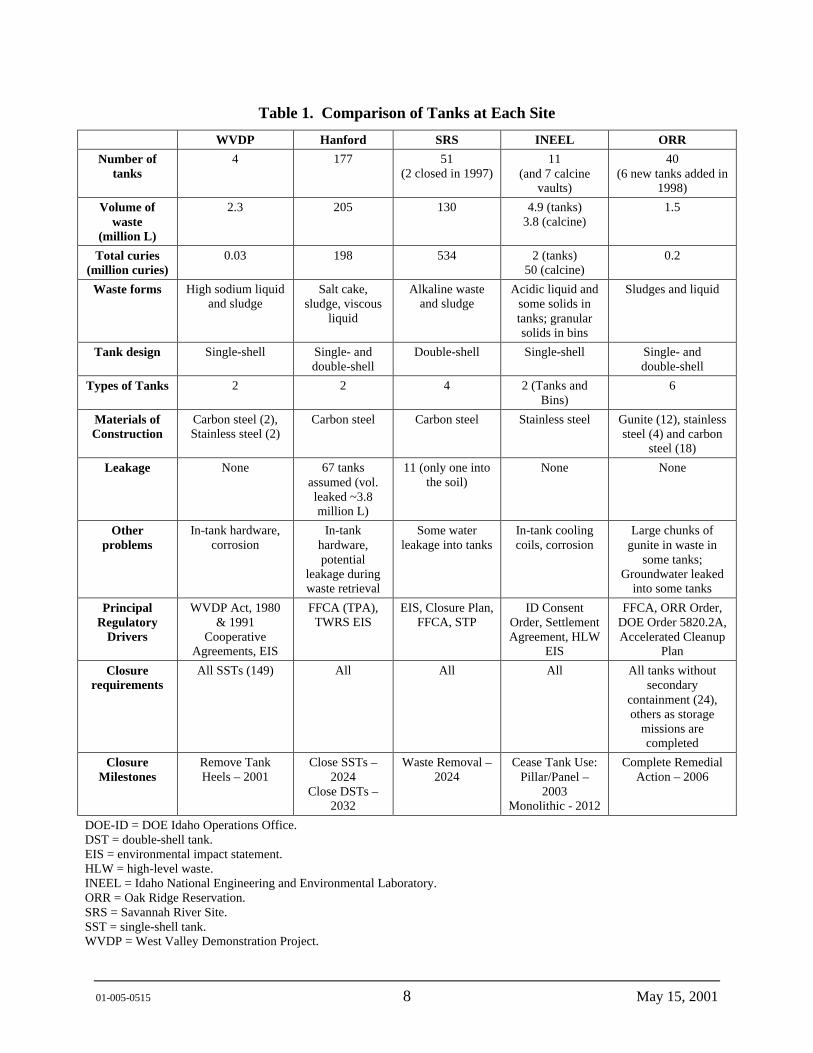
The DOE currently stores about 340 million L (90 million gal) of waste containing more than 700 million curies of radioactivity. Table 1 provides a summary of the tanks and stored waste. The tank wastes differ both physically and chemically between sites, between tanks on a site, and in some cases, between phases of waste within a tank.
When generated, HLW is a highly radioactive, acidic liquid that generates heat and must be handled remotely behind heavy shielding in corrosion-resistant vessels, usually made of stainless steel. At the Hanford Site (Hanford), because stainless steel was in short supply, HLW was neutralized with caustic soda (sodium hydroxide), and sodium nitrite was then added for corrosion control so that the HLW could be stored safely in carbon-steel tanks. This practice continued at Hanford, the SRS, and the WVDP, even when stainless steel became more readily available.
Neutralization with caustic soda forms sodium nitrate (which remains in solution) and hydrated oxides of certain radionuclides and non-radioactive chemicals (which precipitate and collect as a sludge on the floor of the tank). The 137 Cs remains largely in solution. The supernatant liquid resulting from neutralization may also become concentrated by evaporation--either by self-boiling or in evaporators. If enough water is removed from the waste, sodium nitrate and sodium nitrite will crystallize from the solution. The crystals then will settle to the bottom of the tank liquid. If there are many crystals, a salt cake will form on top of the liquid.
01-005-0515 8 May 15, 2001
Table 1. Comparison of Tanks at Each Site
WVDP Hanford SRS INEEL ORR Number of
tanks 4 177 51
(2 closed in 1997) 11
(and 7 calcine vaults)
40 (6 new tanks added in
1998)
Volume of waste
(million L)
2.3 205 130 4.9 (tanks) 3.8 (calcine)
1.5
Total curies (million curies)
0.03 198 534 2 (tanks) 50 (calcine)
0.2
Waste forms High sodium liquid and sludge
Salt cake, sludge, viscous
liquid
Alkaline waste and sludge
Acidic liquid and some solids in tanks; granular solids in bins
Sludges and liquid
Tank design Single-shell Single- and double-shell
Double-shell Single-shell Single- and double-shell
Types of Tanks 2 2 4 2 (Tanks and Bins)
6
Materials of Construction
Carbon steel (2), Stainless steel (2)
Carbon steel Carbon steel Stainless steel Gunite (12), stainless steel (4) and carbon
steel (18)
Leakage None 67 tanks assumed (vol. leaked ~3.8 million L)
11 (only one into the soil)
None None
Other problems
In-tank hardware, corrosion
In-tank hardware, potential
leakage during waste retrieval
Some water leakage into tanks
In-tank cooling coils, corrosion
Large chunks of gunite in waste in
some tanks; Groundwater leaked
into some tanks
Principal Regulatory
Drivers
WVDP Act, 1980 & 1991
Cooperative Agreements, EIS
FFCA (TPA), TWRS EIS
EIS, Closure Plan, FFCA, STP
ID Consent Order, Settlement Agreement, HLW
EIS
FFCA, ORR Order, DOE Order 5820.2A, Accelerated Cleanup
Plan
Closure requirements
All SSTs (149) All All All All tanks without secondary
containment (24), others as storage
missions are completed
Closure Milestones
Remove Tank Heels – 2001
Close SSTs – 2024
Close DSTs – 2032
Waste Removal – 2024
Cease Tank Use: Pillar/Panel –
2003 Monolithic - 2012
Complete Remedial Action – 2006
DOE-ID = DOE Idaho Operations Office. DST = double-shell tank. EIS = environmental impact statement. HLW = high-level waste. INEEL = Idaho National Engineering and Environmental Laboratory. ORR = Oak Ridge Reservation. SRS = Savannah River Site. SST = single-shell tank. WVDP = West Valley Demonstration Project.
01-005-0515 9 May 15, 2001
The Hanford Site performed several different separations processes during plutonium production, and additional operations such as uranium, cesium, and strontium recovery. As a result, there are several different waste types at the Hanford Site. WVDP wastes were generated from commercial reprocessing of uranium and plutonium from SNF. ORR wastes are similar in composition to wastes at the Hanford Site and SRS because, during World War II, ORR developed and demonstrated many of the chemical separations processes used at those sites.
At INEEL, however, the waste has always been stored as an acidic liquid in stainless steel tanks. The majority of INEEL’s waste has been calcined (converted to a dry, granular powder similar in consistency to dry laundry detergent), which is considered an interim storage waste form by the State of Idaho. Calcine waste requires further processing to convert it to a more durable, long-term waste form. In addition, INEEL has some tank-heel waste remaining that must be addressed.
Each site is at a different stage in remediation of its wastes and closure of tanks. All of the sites require technical assistance, scientific data, technology development, and baseline technology performance verification to improve efficiency, reduce costs, reduce risks, and enable the baseline tank waste remediation and closure activities to be implemented.
7.0 SITE-SPECIFIC DESCRIPTIONS
7.1 HANFORD SITE
The Hanford Site currently manages approximately 205 million L (54 million gal) of HLW in 177 under-ground carbon steel tanks (149 single-shell tanks [SSTs] and 28 DSTs. The waste consists of highly alkaline sludge, saltcake, slurry, and liquids.
The SSTs were constructed between 1944 and 1964 and received waste until 1980. The capacity of most SSTs is approximately 2 to 4 million L (500,000 to 1 million gal). The tanks are situated below grade and are covered with 2 to 3 m (6 to 10 ft) of earth. The 149 SSTs contain about 140 million L (36 million gal) of waste. Sixty-seven of the SSTs tanks have leaked or are assumed to have leaked. Approximately 2.3 million to 3.4 million L (600,000 to 900,000 gal) of waste has leaked or spilled into the nearby soil. Over the years, much of the liquid stored in SSTs has evaporated or been pumped to DSTs.
The Hanford Site tanks are cylindrical reinforced concrete structures with inner carbon-steel liners. The 149 SSTs have a single carbon-steel liner, and the 28 DSTs have two steel liners separated by a space called the annulus. The domes of the SSTs are made of concrete without a steel inner liner. The DSTs are completely enclosed by steel and reinforced by a concrete shell.
In the 200 East and 200 West Areas, the tanks were built in 18 groups called tank farms; 12 are SST farms and 6 are DST farms. The farms each contain from 2 to 16 tanks and hold different amounts of waste. The farms contain underground pipes so the waste can be pumped between tanks, between tank farms, from different facilities, and between the 200 East and 200 West Areas. The farms also house equipment used to route the waste, such as diversion boxes and valve pits.
01-005-0515 10 May 15, 2001
7.1.1 Single-Shell Tanks
The 149 SSTs are located in 12 tank farms. The SSTs are constructed of carbon-steel that is ASTM A283 Grade C or ASTM A201 Grade C (AX tank farm), which lines the bottom and sides of a reinforced concrete shell. The bottoms of most tanks are slightly dished. The tanks are below grade with at least 1.83 m (6 ft) of soil cover that provides shielding, thereby minimizing radiation exposure to operating personnel. Inlet and overflow lines are located near the top of the liner. The volume capacity of each tank varies from 208,000 L to 3.8 million L (55,000 to 1 million gal). One hundred thirty-three of the SSTs are 22.86 m (75 ft) in diameter and 9.07 to 16.46 m (29.75 to 54 ft) high (at their highest points), with nominal capacities of 1.9 million to 3.8 million L (500,000 to 1 million gal). The larger tanks are numbered in the 100-series. Sixteen of the tanks are smaller units of a similar design, 6.1 m (20 ft) in diameter and 7.77 m (25.5 ft) high with capacities of 208,000 L (55,000 gal). The smaller tanks are numbered in the 200-series. Access to the tanks is provided by risers penetrating the domes of the tanks. Risers vary in diameter from 10 cm to 1.1 m (4 to 42 in.).
The carbon-steel liners used in the Hanford Site SSTs were not stress relieved after fabrication. The hot, alkaline radioactive waste mixture of liquid plus sludge has induced stress-corrosion cracking of the steel in some tanks.
Forced ventilation provides cooling for tanks containing materials that, through radioactive decay, generate heat that could exceed the established concrete temperature limits. Single-stage, high-efficiency particulate air filters allow atmospheric breathing for tanks that do not require cooling. Most of the waste in the SSTs is in the form of sludge, salt cake, and pumpable and nonpumpable liquids. Sludge consists of the solids (i.e., hydrous metal oxides) precipitated from the neutralization of acid waste before their transfer to the SSTs. Salt cake is made up of the various salts formed from the evaporation of water from the waste. Pumpable liquid exists as supernate and interstitial liquid in the tanks.
The SST waste is comprised primarily of sodium hydroxide; sodium salts of nitrate, nitrite, carbonate, aluminate, and phosphate; and hydrous oxides of aluminum, iron, and manganese. The radioactive components are fission product radionuclides such as strontium-90, cesium-137, and iodine-129 and of actinide elements such as uranium, neptunium, plutonium, thorium, and americium. The best-basis inventory (BBI 2001) contains a more complete description of tank contents.
The SSTs contain mostly inorganic waste, although relatively small amounts of plant solvents were added during fuel reprocessing. Water-soluble complexing agents and carboxylic acids were added in the B Plant waste fractionation process.
Waste management operations have created a complex intermingling of the tank waste. Nonradioactive chemicals have been added to the tanks to enhance storage capabilities, while varying amounts of waste and heat-producing radionuclides have been removed. Additionally, natural processes have caused settling, stratification, and segregation of waste components. Waste was also cascaded (i.e., allowed to gravity-flow from one tank to another) through a series of tanks; cooling and precipitation of radionuclides and solids occurred in each tank of the
01-005-0515 11 May 15, 2001
cascade. As a result, it is difficult to estimate the character of the waste contained in the tanks through operation records.
Of the 149 SSTs, 126 have been interim stabilized (including all but 2 of the 67 assumed leakers). An interim stabilized tank contains less than 189,000 L (50,000 gal) of drainable interstitial liquid and less than 19,000 L (5,000 gal) of supernate liquid. If the tank was jet pumped to achieve interim stabilization, then the jet pump flow or saltwell screen inflow must also have been at or below 0.19 L/min (0.05 gal/min) before interim stabilization criteria are met.
7.1.2 Hanford Double-Shell Tanks
There are 28 DSTs at the Hanford Site, each with a capacity of about 3.8-million L (1-million gal). The DSTs were constructed between 1970 and 1986. DSTs consist of two concentric structures; a steel primary tank used to contain radioactive waste materials; and an outer reinforced concrete confinement structure lined with steel. The space between the two walls is monitored for leaks. These tanks are also situated 2 to 3 m (6 to 10 ft) below ground level. DOE has used DSTs since 1970 and none of the DSTs at the Hanford Site have been known to leak. They are used to store a variety of liquid radioactive wastes including wastes from the SSTs interim stabilization program and from various Hanford Site processes. The wastes are stored in tanks based on composition, level of radioactivity, or origin. The 28 DSTs now contain about 80 million L (21 million gal) of waste (HNF-EP-0182-155).
7.1.3 Path to Closure for the Hanford Site
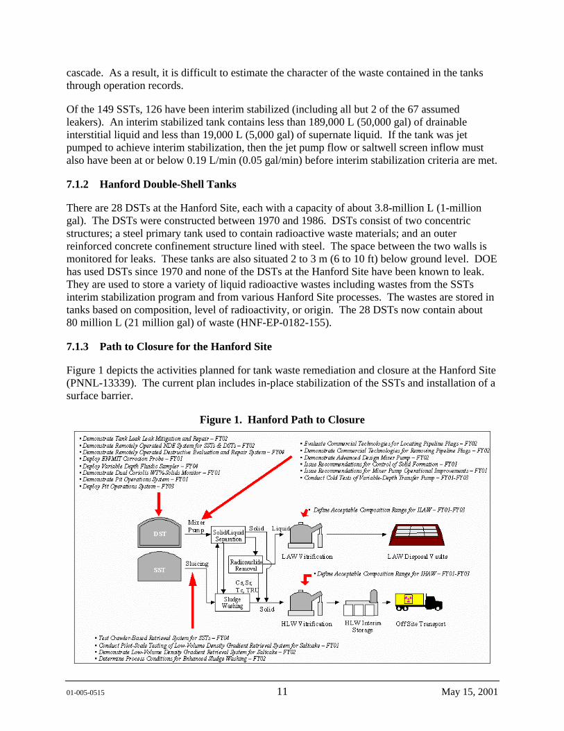
Figure 1 depicts the activities planned for tank waste remediation and closure at the Hanford Site (PNNL-13339). The current plan includes in-place stabilization of the SSTs and installation of a surface barrier.
Figure 1. Hanford Path to Closure
01-005-0515 12 May 15, 2001
7.1.4 Regulatory Drivers for the Hanford Site
Regulatory drivers for remediating tank wastes at the Hanford Site include the following.
• Hanford Federal Facility Agreement and Consent Order (Ecology et al. 1989) (Tri-Party Agreement). This agreement between the U.S. Environmental Protection Agency (EPA) Region X, the DOE, and the Washington State Department of Ecology established the requirements for meeting federal and State Resource Conservation and Recovery Act of 1976 (RCRA) regulations. The Hanford Federal Facility Agreement and Consent Order was originally signed in 1989, and has been amended numerous times. The fourth amendment committed DOE to retrieval of waste from the SSTs, vitrification of low-level waste (LLW), cessation of the grout program, and the National Environmental Policy Act of 1969 coverage of actions. The most recent change implements a risk reduction strategy for SST waste retrieval, requires a demonstration of waste retrieval goals, and requires the establishment of an interface with the U.S. Nuclear Regulatory Commission (NRC) to reach agreement on allowable waste residuals in the tank and soil column. The Tri-Party Agreement serves as the site treatment plan required under the Federal Facility Compliance Act of 1992.
• Environmental Impact Statement for the Tank Waste Remediation System (DOE/EIS-0189). The environmental impact statement (EIS) provides information that has the potential to rebaseline tank waste remediation at the Hanford Site. The environmental consequences of a number of alternatives for treating tank waste, including in situ treatment, are evaluated. A record of decision (ROD) for the Tank Waste Remediation System EIS (62 FR 8693) stated that the phased approach was the best path forward for treating tank wastes.
• Hanford Comprehensive Land-Use Plan EIS (DOE/EIS-0222F). DOE has developed a land use plan for the Hanford Site that is included in the EIS for Hanford Site remedial actions. The Draft EIS was released in 1996, and the Final issued in 1999; the ROD was issued in 1999 (64 FR 61615). The plan and the ROD for the EIS identify land uses and accompanying restrictions for major site areas. The future land use assumed for the 200 Areas is industrial and/or commercial. This area will likely be held exclusively for disposal, containment, and management of waste, and other compatible uses. Access to the area and use of the groundwater is assumed to be restricted indefinitely.
• DOE/Ecology Retrieval Performance Objectives Memorandum of Understanding (MOU 1996). The memorandum of understanding specifies cost, risk, and safety as some of the key parameters that must be evaluated in comparing the interim retrieval goal to agreed-on performance objectives based on techniques developed and demonstrated in tank retrieval.
• Defense Nuclear Facilities Safety Board Recommendation 93-5 (DOE/RL-00-01). The board issued recommendations to accelerate tank waste sampling at the Hanford Site to ensure adequate protection of public health and safety. Safety-related sampling and analyses were to be completed by July 1995. These deadlines have not been met.
01-005-0515 13 May 15, 2001
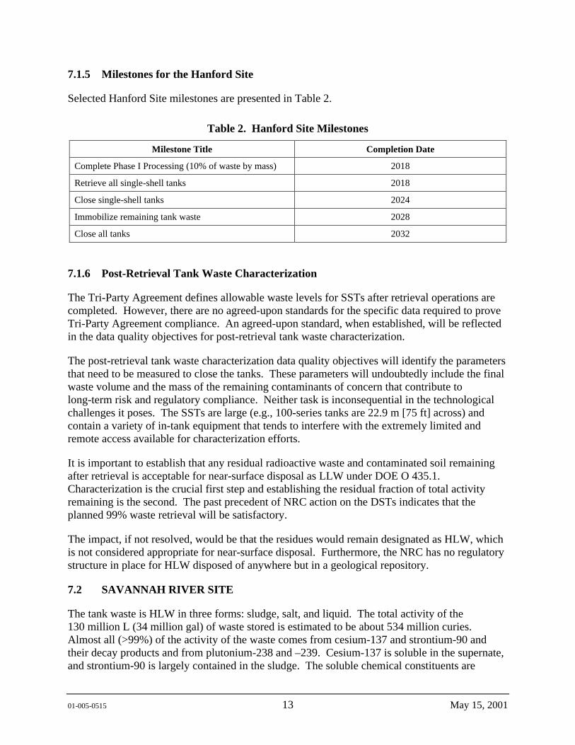
7.1.5 Milestones for the Hanford Site
Selected Hanford Site milestones are presented in Table 2.
Table 2. Hanford Site Milestones
Milestone Title Completion Date
Complete Phase I Processing (10% of waste by mass) 2018
Retrieve all single-shell tanks 2018
Close single-shell tanks 2024
Immobilize remaining tank waste 2028
Close all tanks 2032
7.1.6 Post-Retrieval Tank Waste Characterization
The Tri-Party Agreement defines allowable waste levels for SSTs after retrieval operations are completed. However, there are no agreed-upon standards for the specific data required to prove Tri-Party Agreement compliance. An agreed-upon standard, when established, will be reflected in the data quality objectives for post-retrieval tank waste characterization.
The post-retrieval tank waste characterization data quality objectives will identify the parameters that need to be measured to close the tanks. These parameters will undoubtedly include the final waste volume and the mass of the remaining contaminants of concern that contribute to long-term risk and regulatory compliance. Neither task is inconsequential in the technological challenges it poses. The SSTs are large (e.g., 100-series tanks are 22.9 m [75 ft] across) and contain a variety of in-tank equipment that tends to interfere with the extremely limited and remote access available for characterization efforts.
It is important to establish that any residual radioactive waste and contaminated soil remaining after retrieval is acceptable for near-surface disposal as LLW under DOE O 435.1. Characterization is the crucial first step and establishing the residual fraction of total activity remaining is the second. The past precedent of NRC action on the DSTs indicates that the planned 99% waste retrieval will be satisfactory.
The impact, if not resolved, would be that the residues would remain designated as HLW, which is not considered appropriate for near-surface disposal. Furthermore, the NRC has no regulatory structure in place for HLW disposed of anywhere but in a geological repository.
7.2 SAVANNAH RIVER SITE
The tank waste is HLW in three forms: sludge, salt, and liquid. The total activity of the 130 million L (34 million gal) of waste stored is estimated to be about 534 million curies. Almost all (>99%) of the activity of the waste comes from cesium-137 and strontium-90 and their decay products and from plutonium-238 and –239. Cesium-137 is soluble in the supernate, and strontium-90 is largely contained in the sludge. The soluble chemical constituents are
01-005-0515 14 May 15, 2001
primarily sodium salts such as sodium nitrate (49 wt%), sodium nitrite (12 wt%), sodium hydroxide (13 wt%), sodium-aluminum tetrahydroxide (11 wt%), sodium sulfate (6 wt%), and sodium carbonate (5 wt%). The chemical composition of the insoluble sludges is primarily aluminum oxide (33 wt%), iron oxide (30 wt%), silicon oxide (6 wt%), sodium nitrate/nitrite salts (6 wt%), and zeolite (4 wt%) (HLW-TEC-950027).
Some 310 million L (82 million gal) of tank waste have been generated at SRS since the 1950s. Evaporation has reduced this volume by 60% to about 130 million L (34 million gal). Beginning in 1955 and 1957, tritium was separated and processed in the site’s F and H Areas, respectively.
All of the tanks produce hydrogen as the water and trace organic compounds in the tank are broken down by action of the radioactivity. Tank 48 contains significant quantities of sodium tetraphenylborate, which was used in the in-tank precipitation process. This compound decomposes to produce benzene, which can volatilize and form a flammable vapor in the tank. To mitigate this problem, the tank has a primary and backup nitrogen inerting system that fills and mixes the vapor space with nitrogen, eliminating oxygen in the tank vapor space and, thus, preventing a fire or explosion.
Eleven of the SRS tanks (Type I, II and IV) have exhibited signs of leakage. Five of the Type I tanks are believed to have leaked (1F, 9-12H). All four Type II tanks are known to have leaked significant amounts to the secondary steel pan (13-16H). Tank 16 exhibits the most cracking with over 300 cracks detected. The largest of these cracks is approximately 15 cm (6 in.) long. In September 1960, a maximum of 2,650 L (700 gal) of waste rose above the top of the steel secondary containment pan of this tank for about 6 hours. Most of the 2,650 L (700 gal) was contained within the annular space by the concrete encasement, and was transferred to another tank. However, monitoring of the area indicates some radioactivity did escape through the thick-walled concrete encasement containment structures. Based on available information, a few tens of gallons of waste may have leaked into the soil. Two of the Type IV tanks (19F and 20F) have had minor water incursions. All of the cracks that have been detected are perpendicular to the welds with stress corrosion cracking being the likely failure mechanism. General and pitting corrosion damage do not appear to have caused significant damage.
Fairly recently, a long and unusually shaped crack was found in Tank 15. This crack was detected by visual means, and while it is not well characterized, estimates place it between 12 and 15 in. long. Prior to finding this crack in Tank 15, the longest measured crack was 6 in.
7.2.1 Storage Tanks at the Savannah River Site
The waste storage tanks were built from 1951 to 1981. They were built with three different sizes and four different designs, and are designated as Types I through IV (the labeling system does not denote the chronological order in which the tanks were built).
7.2.1.1 Type I Tanks. There are twelve 2.8-million-L- (750,000-gal-) capacity Type I tanks (Tanks 1 - 12) built between 1951 and 1954 at the H and F tank farm sites. The tanks were manufactured from A285 Grade B steel plate, which was welded together. No stress relieving was performed on these tanks. The primary tank rests in a steel pan that extends 1.5 m (5 ft) up the sidewall. The tanks are 22.5 m (75 ft) in diameter and approximately 7.5 m (25 ft) high.

01-005-0515 15 May 15, 2001
The tanks and liners are encased in a concrete vault. There are twelve concrete columns within the primary tank to support the flat top. The columns are 0.6 m (2 ft) in diameter and encased in carbon steel plate. There are four 13-cm (5-in.) diameter risers providing access to the annulus area. There are 36 parallel cooling water coils suspended from the top of each tank.
Five Type I tanks (Tanks 1 and 9 - 12) have leaked detectable amounts of waste from the primary to the secondary containment, but there is no evidence that waste has leaked from the secondary containment. The tank tops are about 2.9 m (9.5 ft) below grade. Tanks 9 - 12 are located in the H Area Tank Farm and are in the water table.
7.2.1.2 Type II Tanks. There are four Type II tanks (Tanks 13 - 16) built during 1955 and 1956. All four are located in the H-Area Tank Farm. These 3.9-million-L- (1,030,000-gal-) capacity tanks were fabricated from A285, Grade B steel. No stress relieving was performed after welding. The tanks have a diameter of 25.5 m (85 ft) and a height of 8 m (27 ft). The primary tank sits in a steel pan that extends 1.5 m (5 ft) up the sidewalls. Each tank is encased in a concrete vault with a flat top that is supported by a single central column. A 0.7-m (2-½-ft) wide annulus area separates the primary tank from the vault wall around the outside diameter of the tank. There are 13-cm (5-in.) access risers into the annulus that allow 85 to 90 percent of the tank wall to be inspected. The tanks have 44 parallel cooling water coils suspended from the top of the tank.
All four Type II tanks are known to have leaked detectable amounts of waste from the primary to secondary containment. In Tank 16, waste overflowed the annulus pan (secondary containment) and migrated into the surrounding soil. Waste removal from the Tank 16 primary vessel was completed in 1980, but waste that leaked into the annulus has not been removed. These tanks are situated above the seasonal high water table.
7.2.1.3 Type III Tanks. The newest design, Type III, has a full-height secondary tank and forced water cooling. All of the Type III Tanks (Tanks 25 - 51) are situated above the water table. The 27 Type III tanks were constructed from 1967 to 1982. These tanks have a 2.8-million-L (1,300,000-million-gal-) capacity. The steel used to manufacture these tanks gradually evolved to include grades that were more resistant to stress corrosion cracking and had better fracture toughness properties. See Table 3 for a list of the materials used. All welds were stress-relieved. The Type III tanks are 25.5 m (85 ft) in diameter and 10 m (33 ft) high, and have provisions for better air circulation on the outside of the tank walls. Each tank is encased in a concrete vault with a flat top that is supported by a single central column. The vault is lined with a steel secondary containment liner. A 0.7 m (2 ½ ft) wide annulus area separates the primary tank from the secondary containment liner around the outside diameter of the tank. Eight-inch risers into the annulus area allow for access to 100 percent of the tank’s circumference. A small airspace was provided between the central support column and the tank wall, and air slots were incorporated under the tank floor. Tanks 29 to 35 have removable cooling coil bundles suspended from the top of the tank.

01-005-0515 16 May 15, 2001
Table 3. Summary of Storage Tanks at the Savannah River Site
Tank No. Type Construction Date
Steel Specification – Primary Tank
Stress Relieved
Suspected Leakers
1-8 F I 1951–1953 A285 Grade B No 1F
9-12 H I 1951-1953 A285 Grade B No 9-12H
13-16 H II 1955-1958 A285 Grade B No 13-16H
17-20 F IV 1958 A285-54T Grade B No 19-20F
21-24 H IV 1962 A212-57T Grade B No
25-28 F III 1975-1978 A516 Grade 70 (N) Yes
29-32 H III 1967-1970 A516 Grade 70 Yes
33-34 F III 1969-1972 A516 Grade 70 Yes
35-37 H III 1974-1977 A516 Grade 70 (N) Yes
38-43 H III 1976-1980 A537 Class I (N) Yes
44-47 F III 1977-1980 A537 Class I (N) Yes
48-51 H III 1978-1981 A537 Class I (N) Yes
These tanks contain the majority of the waste at SRS. Though none of these tanks is known to have leaked, there has been minor water leakage into two tanks. Most of the site's tank waste radioactivity and tank waste volume is contained in these 27 tanks.
The Type III tanks still receive small amounts of HLW from the site’s limited production activities. Two types of waste are being sent: high-heat waste, which contains most of the radionuclides and must be aged in a high-heat waste tank before evaporation; and low-heat waste. After the waste is put in the Type III tanks, it separates into a bottom sludge layer and an upper layer of dissolved salts.
7.2.1.4 Type IV Tanks. The Type IV tanks were constructed from 1958 to 1962 and have a capacity of 1,300,000 gal. The tanks are 25.5 m (85 ft) in diameter and have 10-m (34-ft) high concrete sidewalls with a steel liner. The liners of the Type IV tanks were not stress relieved after welding. The tanks have a dome covering and do not contain cooling coils.
There were eight Type IV Tanks. Tanks 17 - 20 are located in the F-Area Tank Farm and Tanks 21 - 24 are located in H Area. Tanks 17 - 20 are slightly above the water table. Tanks 21 - 24 are above the groundwater table. However, they are in a perched water table caused by the original basemat under the tank area. Monitoring records suggest that a small amount of water has leaked into two of these tanks (Tanks 19 and 20), but there is no evidence that waste ever leaked out. Waste was removed from one Type IV tank because of a leak that developed in its carbon steel liner. Waste was removed from two other Type IV tanks (Tanks 17 and 20), and the tanks were grouted and closed in 1997.
01-005-0515 17 May 15, 2001
7.2.2 Savannah River Site High-Level Waste Treatment and Tank Closure
The SRS HLW is being treated to separate the high-activity fraction (sludge) from the low activity fraction (liquid). The high-activity fraction is transferred to the Defense Waste Processing Facility (DWPF) for vitrification in borosilicate glass to immobilize the radioactive constituents for long-term storage. Final disposal of the vitrified waste will proceed after the transfer to a federal repository. The low-activity fraction is transferred to Z Area and mixed with grout to make saltstone, a concrete-like material disposed of in vaults. The environmental impacts of these processes and facilities were evaluated in the DWPF Supplemental EIS (DOE/EIS-0082S) and Waste Management EIS (DOE/EIS-0217).
After the bulk waste has been removed from the tanks for treatment and disposal, the tank systems would become part of the tank systems closure project. The primary concerns are how to deal with the waste that cannot be removed from the bottom of a tank (referred to as a heel) and tank stabilization methods. As outlined in the Closure Plan (DOE/EIS-0303D), DOE intends to close the tank systems to protect human health and the environment, and promote safety in and around these tank systems in accordance with South Carolina Regulation R.61-82, “Proper Closeout of Wastewater Treatment Facilities.”
Upon completion of closure activities for geographical groups of tanks and waste handling systems, including evaporators, pumps, and transfer lines under this plan, portions of the HLW tank farms would transition from the tank closure project to the SRS Environmental Restoration program.
The proposed action is to remove the residual wastes from the tanks and to fill the tanks with a material to prevent future collapse and bind up residual waste, to lower human health risks, and to increase safety in and around the tanks. If required, an engineered cap consisting of clay, backfill (soil), and vegetation as the final layer to prevent erosion would be applied over the tanks. The selection of tank system closure method will be evaluated against the following Comprehensive Environmental Response, Compensation, and Liability Act of 1980 criteria described in 40 CFR 300.430(e)(9): (1) overall protection of human health and the environment; (2) compliance with applicable or relevant and appropriated requirements; (3) long-term effectiveness and permanence; (4) reduction of toxicity, mobility, or volume through treatment; (5) short-term effectiveness; (6) implementability; (7) cost; (8) state acceptable; and (9) community acceptance.
7.2.3 Path to Closure for the Savannah River Site
In accordance with the SRS Federal Facility Agreement between DOE, EPA, and the South Carolina Department of Health and Environmental Control (SCDHEC) (Docket No. 89-05-FF), DOE intends to remove the tanks from service as their storage missions are completed. DOE is obligated to close 24 tanks that do not meet EPA’s secondary containment standards under RCRA by 2022. The 24 Type I, II, and IV tanks have been or will be removed from service before the 27 Type III tanks. Type III tanks will remain in service until there is no further need for them, which DOE currently anticipates to occur before the year 2030.
01-005-0515 18 May 15, 2001
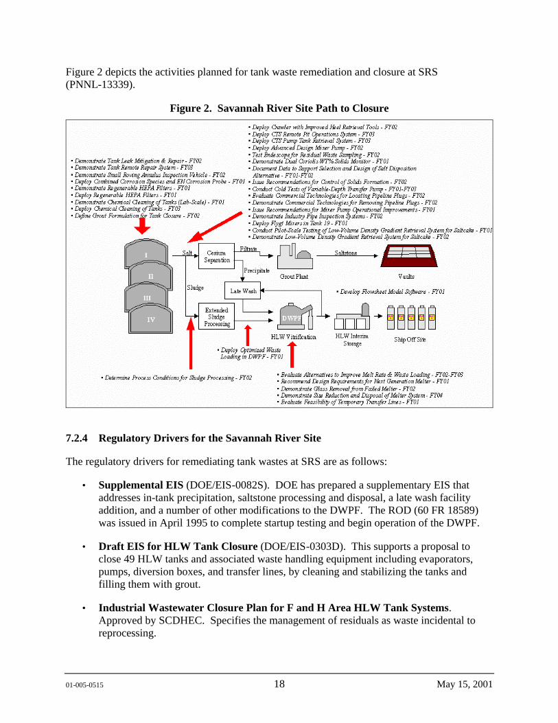
Figure 2 depicts the activities planned for tank waste remediation and closure at SRS (PNNL-13339).
Figure 2. Savannah River Site Path to Closure
7.2.4 Regulatory Drivers for the Savannah River Site
The regulatory drivers for remediating tank wastes at SRS are as follows:
• Supplemental EIS (DOE/EIS-0082S). DOE has prepared a supplementary EIS that addresses in-tank precipitation, saltstone processing and disposal, a late wash facility addition, and a number of other modifications to the DWPF. The ROD (60 FR 18589) was issued in April 1995 to complete startup testing and begin operation of the DWPF.
• Draft EIS for HLW Tank Closure (DOE/EIS-0303D). This supports a proposal to close 49 HLW tanks and associated waste handling equipment including evaporators, pumps, diversion boxes, and transfer lines, by cleaning and stabilizing the tanks and filling them with grout.
• Industrial Wastewater Closure Plan for F and H Area HLW Tank Systems. Approved by SCDHEC. Specifies the management of residuals as waste incidental to reprocessing.
01-005-0515 19 May 15, 2001
• Savannah River Federal Facility Consent Agreement. This is an agreement between EPA Region IV, DOE, and the SCDHEC. This agreement establishes requirements for remediation of SRS. Tanks must meet structural integrity requirements or be removed from service.
• Savannah River Waste Management EIS (DOE/EIS-0217). This sitewide EIS provides the basis to select processes to manage wastes generated from ongoing operations and the operation of the Consolidated Incineration Facility. The ROD from this EIS (60 FR 55249) documents the decision to construct and operate the HLW evaporator and to transfer waste from the storage tanks to the DWPF.
• Site Treatment Plan (HLW-TEC-950027). The Federal Facility Compliance Act requires a site treatment plan for treating and disposing of mixed wastes. The SRS Site Treatment Plan identifies the DWPF as the preferred treatment option for treating liquid HLW.
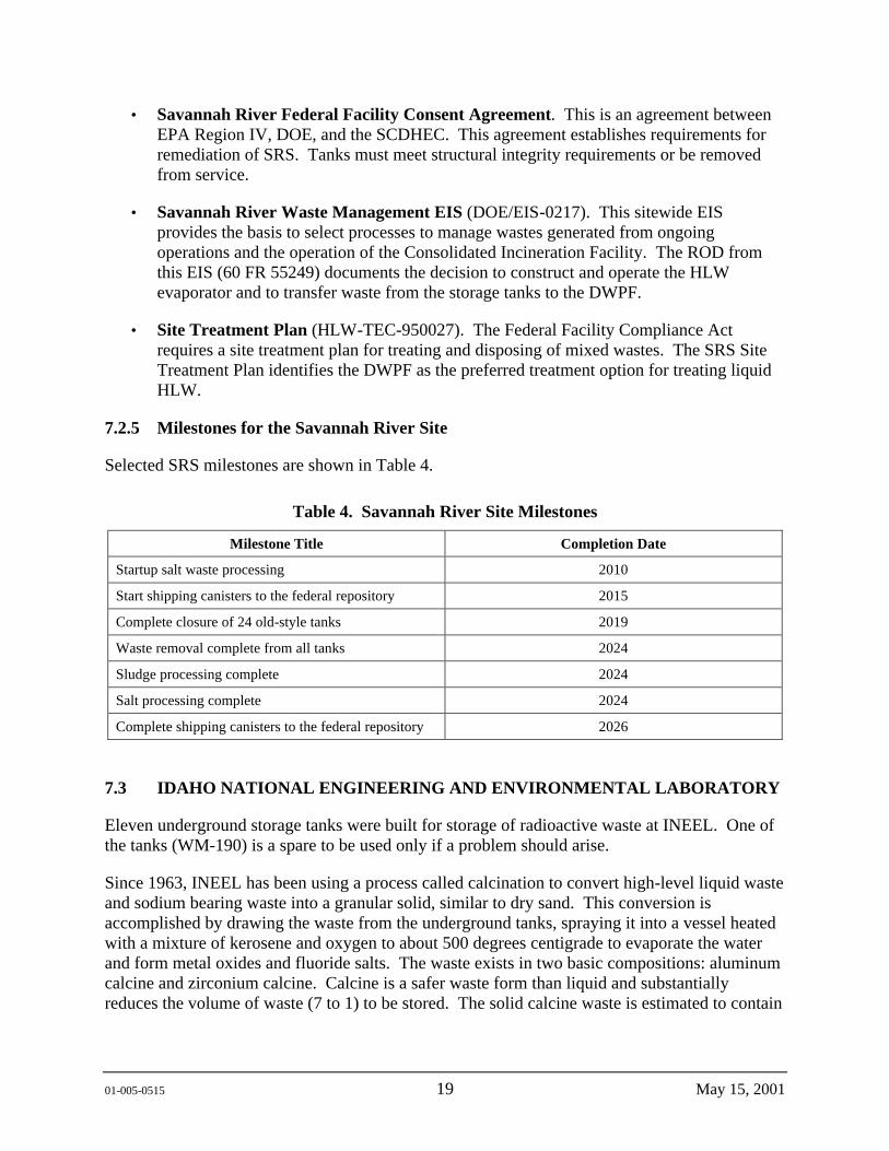
7.2.5 Milestones for the Savannah River Site
Selected SRS milestones are shown in Table 4.
Table 4. Savannah River Site Milestones
Milestone Title Completion Date
Startup salt waste processing 2010
Start shipping canisters to the federal repository 2015
Complete closure of 24 old-style tanks 2019
Waste removal complete from all tanks 2024
Sludge processing complete 2024
Salt processing complete 2024
Complete shipping canisters to the federal repository 2026
7.3 IDAHO NATIONAL ENGINEERING AND ENVIRONMENTAL LABORATORY
Eleven underground storage tanks were built for storage of radioactive waste at INEEL. One of the tanks (WM-190) is a spare to be used only if a problem should arise.
Since 1963, INEEL has been using a process called calcination to convert high-level liquid waste and sodium bearing waste into a granular solid, similar to dry sand. This conversion is accomplished by drawing the waste from the underground tanks, spraying it into a vessel heated with a mixture of kerosene and oxygen to about 500 degrees centigrade to evaporate the water and form metal oxides and fluoride salts. The waste exists in two basic compositions: aluminum calcine and zirconium calcine. Calcine is a safer waste form than liquid and substantially reduces the volume of waste (7 to 1) to be stored. The solid calcine waste is estimated to contain

01-005-0515 20 May 15, 2001
50,000,000 curies of radioactivity. The radioactivity in calcine is primarily due to cesium-137 and strontium-90.
Prior to June 1997, the 11 underground stainless steel tanks contained approximately 6,400 m3 (1.7 million gal) of acidic, radioactive liquid waste. This waste consisted of approximately 1,100 m3 (300,000 gal) of high-level liquid waste and 5,300 m3 (1.4 million gal) of sodium-bearing liquid waste. In 1997, Idaho Nuclear Technology and Engineering Center (INTEC) (formerly the Idaho Chemical Processing Plant) initiated a campaign to calcine all of the remaining high-level liquid waste by June 1998 to meet the Settlement Agreement with the State of Idaho. As of September 30, 2000, the total volume of waste in the 11 tanks had been reduced to 4.9 million L (1.3 million gal). This waste is primarily comprised of nitrates, sodium, aluminum, zirconium, and fluorides. The waste contains approximately 2,000,000 curies of radionuclides, with most of the radioactivity due to cesium-137 and strontium-90.
For INEEL, HLW projections are based on the recommended option from a new systems engineering approach to integrate all DOE Office of Environmental Management waste streams at the INEEL. The HLW projections include streams associated with the intermediate calcining of liquid waste, followed by separation of HLW and LLW fractions in the remaining liquid waste and redissolved calcine. No new HLW from reprocessing activities was produced after fiscal year 1992; SNF reprocessing facilities are being placed into cold standby pending decontamination and decommissioning. The current reference waste form at INEL is a glass. According to the October 17, 1995, Settlement Agreement, INEL is to calcine all of the liquid waste currently stored in the tanks by December 31, 2012. All of the HLW must be treated to be converted to the final waste form and be “road ready” by December 31, 2035. It is assumed that INEL will begin radioactive operations and thus produce canisters in 2020 and continue this operation through 2035.
7.3.1 Characteristics of Idaho National Engineering and Environmental Laboratory Tank Waste
Approximately 5.3 million L (1.4 million gal) of radioactive liquid waste containing 520,000 Ci of radioactivity are stored as acidic solutions in INTEC 11 tanks. The tank waste consists of sodium-bearing waste generated from activities incidental to reprocessing, such as facility decontamination.
In general, the tank waste at INTEC is different from the waste at the other DOE tank sites. The INTEC waste is extremely acidic, with a pH of less than 1 and is characterized by large concentrations of nitrates and dissolved metals such as aluminum, potassium, and sodium with small concentrations of sulfates, chlorides, and heavy metals such as chromium and nickel (WHC-EP-0566). The liquid waste has a density of 1.1 to 1.3 g/cm3 (WHC-EP-0566).
The waste is composed predominantly of nitric acid and sodium nitrate. Small amounts of fission products and TRU elements are also in the waste. Some of the major constituents of waste by molarity (nominal) are nitrate, 4.5; sodium, 1.5; acid, 1.3; aluminum, 0.57, and potassium, 0.17. The basic (high pH) waste in the other site’s tanks caused many radioactive and nonradioactive metals to segregate into a complex chemical and physical mixture of liquids, slurries, and sludges.
01-005-0515 21 May 15, 2001
In contrast, the metals and other dissolved material in INTEC’s acidic tank waste remain in solution. Other than a few inches of accumulated solids on the bottom of the tanks, the liquid is clear to the bottom of the tanks. This simplifies waste characterization and retrieval compared to other DOE tank sites.
INTEC’s tank waste has been divided into two categories: high-level liquid waste and sodium-bearing waste. All of the high-level liquid waste resulting from the dissolution and processing of SNF has been calcined and is stored in bin sets. Only sodium-bearing waste remains in storage in the tank farm.
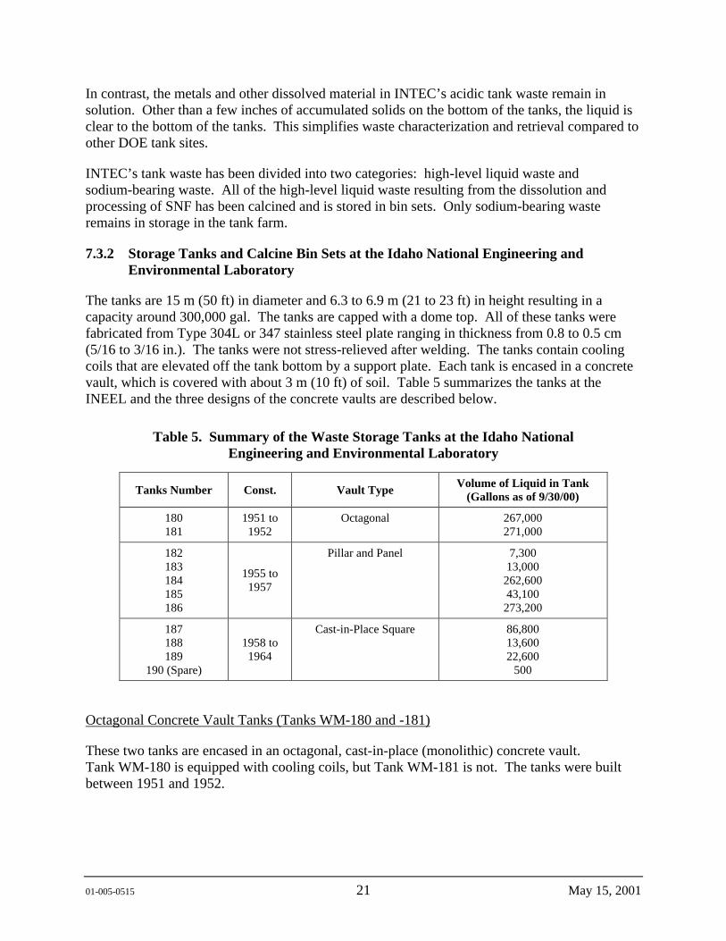
7.3.2 Storage Tanks and Calcine Bin Sets at the Idaho National Engineering and Environmental Laboratory
The tanks are 15 m (50 ft) in diameter and 6.3 to 6.9 m (21 to 23 ft) in height resulting in a capacity around 300,000 gal. The tanks are capped with a dome top. All of these tanks were fabricated from Type 304L or 347 stainless steel plate ranging in thickness from 0.8 to 0.5 cm (5/16 to 3/16 in.). The tanks were not stress-relieved after welding. The tanks contain cooling coils that are elevated off the tank bottom by a support plate. Each tank is encased in a concrete vault, which is covered with about 3 m (10 ft) of soil. Table 5 summarizes the tanks at the INEEL and the three designs of the concrete vaults are described below.
Table 5. Summary of the Waste Storage Tanks at the Idaho National Engineering and Environmental Laboratory
Tanks Number Const. Vault Type Volume of Liquid in Tank (Gallons as of 9/30/00)
180 181
1951 to 1952
Octagonal 267,000 271,000
182 183 184 185 186
1955 to 1957
Pillar and Panel 7,300 13,000
262,600 43,100
273,200
187 188 189
190 (Spare)
1958 to 1964
Cast-in-Place Square 86,800 13,600 22,600
500
Octagonal Concrete Vault Tanks (Tanks WM-180 and -181)
These two tanks are encased in an octagonal, cast-in-place (monolithic) concrete vault. Tank WM-180 is equipped with cooling coils, but Tank WM-181 is not. The tanks were built between 1951 and 1952.
01-005-0515 22 May 15, 2001
Pillar and Panel Vault Tanks (Tanks WM-182 to WM-186)
These five tanks are housed in octagonal vaults that were built with precast concrete pillar and panel components. The tanks were constructed from 1955 to 1957, and all have cooling coils except Tanks WM-184 and WM-186.
Cast-in-Place Square Vault Tanks (Tanks WM-187 to WM-190)
These four tanks are housed in two rectangular, cast-in-place concrete vaults. Each vault contains two tanks. The tanks were built between 1958 and 1964, and all have cooling coils.
In addition to the underground storage tanks, the site also stores waste in seven Calcine Solids Storage Facilities. These facilities were designed to store waste in a granular solid form that is easier to contain and retrieve. The facilities consist of stainless-steel bins encased in concrete vaults. Bin set 1 was constructed from Type 405 stainless steel and the remainder from Type 304 or 304L stainless steel. There are five different configurations to these facilities. The facilities contain a combined 4,386 m3 or about 1,000,000 gal of granular waste called calcine. The Calcine Solids Storage Facilities were designed to have a 500-year life.
The amount of waste is not spread evenly among the 11 tanks. Some tanks are close to capacity while others are not. One of the tanks is empty and has been declared a spare tank. The tanks are similar in design, constructed of stainless steel, and contained in underground concrete vaults. Each tank has four to five access risers. Steam jets are used to transport waste from tanks into the process system.
Eight of the 11 tanks can be cooled using cooling coils located along the tank floors and walls. These cooled tanks were used to contain the wastes and fission products (e.g., cesium-137 and strontium-90) from the thermally hottest first- and second-cycle extraction processes. Chemical raffinate from later extraction cycles and LLW evaporator concentrates were stored in the uncooled tanks. The wastes are stored in the tanks until ready for calcination. To date, none of these tanks has leaked waste to the surrounding environment.
Approximately 3.8 million L (1 million gal) of calcine containing 24 million curies of radioactivity are stored in seven stainless-steel bin sets enclosed in concrete vaults with walls up to 1.2 m (4 ft) thick. Thus, the calcine contains about 98% of the waste radioactivity at INTEC. The bin sets have a network of monitoring systems that include temperature, pressure, and radiation monitors (WHC-EP-0566). Five of the seven storage facilities are full, the sixth is being filled, and the seventh is empty.
The bins have a life expectancy of 400 to 500 years. Radiation doses of 1,000 rem/hr have been measured in the annulus space of these bins. Calcined waste is not an acceptable form for permanent disposal because of concerns that the dry waste could be easily dispersed. Therefore, the calcined waste will be converted to an acceptable final form before disposal in a geologic repository.

01-005-0515 23 May 15, 2001
7.3.3 Path to Closure for the Idaho National Engineering and Environmental Laboratory
Figure 3 depicts the activities planned for tank waste remediation and closure at INEEL (PNNL-13339).
Figure 3. Idaho National Engineering and Environmental Laboratory Path to Closure
7.3.4 Regulatory Drivers for the Idaho National Engineering and Environmental Laboratory
Idaho’s major cleanup issues for INTEC are driven by two regulations: the Notice of Noncompliance Consent Order and the Idaho Settlement Agreement. Also, the Accelerating Cleanup plan plays a significant role.
• Accelerating Cleanup: Paths to Closure (DOE/EM-0362). The plan provides a project-by-project projection of the technical scope, cost, and schedule required to complete all 46 projects at INEEL’s remaining cleanup sites.
• Notice of Noncompliance Consent Order (Cory 1998). The Consent Order, developed by the state, requires DOE Idaho Operations Office to cease use of the five pillar and panel vault tanks by 2009 and to cease use of the remaining six tanks by 2015. An August 1998 modification to the Consent Order accelerated these dates to 2003 and 2012, respectively.
01-005-0515 24 May 15, 2001
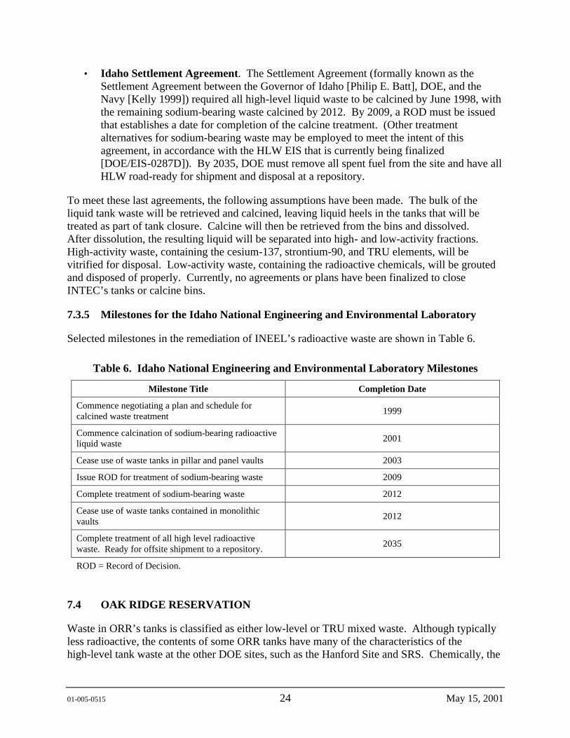
• Idaho Settlement Agreement. The Settlement Agreement (formally known as the Settlement Agreement between the Governor of Idaho [Philip E. Batt], DOE, and the Navy [Kelly 1999]) required all high-level liquid waste to be calcined by June 1998, with the remaining sodium-bearing waste calcined by 2012. By 2009, a ROD must be issued that establishes a date for completion of the calcine treatment. (Other treatment alternatives for sodium-bearing waste may be employed to meet the intent of this agreement, in accordance with the HLW EIS that is currently being finalized [DOE/EIS-0287D]). By 2035, DOE must remove all spent fuel from the site and have all HLW road-ready for shipment and disposal at a repository.
To meet these last agreements, the following assumptions have been made. The bulk of the liquid tank waste will be retrieved and calcined, leaving liquid heels in the tanks that will be treated as part of tank closure. Calcine will then be retrieved from the bins and dissolved. After dissolution, the resulting liquid will be separated into high- and low-activity fractions. High-activity waste, containing the cesium-137, strontium-90, and TRU elements, will be vitrified for disposal. Low-activity waste, containing the radioactive chemicals, will be grouted and disposed of properly. Currently, no agreements or plans have been finalized to close INTEC’s tanks or calcine bins.
7.3.5 Milestones for the Idaho National Engineering and Environmental Laboratory
Selected milestones in the remediation of INEEL’s radioactive waste are shown in Table 6.
Table 6. Idaho National Engineering and Environmental Laboratory Milestones
Milestone Title Completion Date
Commence negotiating a plan and schedule for calcined waste treatment 1999
Commence calcination of sodium-bearing radioactive liquid waste 2001
Cease use of waste tanks in pillar and panel vaults 2003
Issue ROD for treatment of sodium-bearing waste 2009
Complete treatment of sodium-bearing waste 2012
Cease use of waste tanks contained in monolithic vaults 2012
Complete treatment of all high level radioactive waste. Ready for offsite shipment to a repository. 2035
ROD = Record of Decision.
7.4 OAK RIDGE RESERVATION
Waste in ORR’s tanks is classified as either low-level or TRU mixed waste. Although typically less radioactive, the contents of some ORR tanks have many of the characteristics of the high-level tank waste at the other DOE sites, such as the Hanford Site and SRS. Chemically, the
01-005-0515 25 May 15, 2001
waste is principally sodium nitrate, as is the HLW generated from weapons production activities. However, because the U.S. definition of HLW is based on the waste’s origin (waste from processing SNF is classified as HLW regardless of its radioactivity), the site’s waste is not classified as HLW. Nonetheless, the most concentrated of the TRU waste sludge in ORR tanks contains as much radioactivity as some of HLW at other DOE facilities. The waste was created from several sources, including reactor water cleanup, radiochemical process development and processing areas, facility decontamination, and laboratory operations.
The waste in the ORR tanks is mixed LLW or TRU waste. The waste is classified as mixed because it contains both radionuclides (e.g., cesium, strontium, plutonium, uranium, technetium, and ruthenium) and hazardous materials (e.g., lead, chromium, mercury, and some organic compounds). The waste is low- level or TRU (depending on its concentrations of long-lived alpha emitters) because it results from the variety of research and development activities described above.
The ORNL has 95 underground storage tanks with capacities ranging from 40 to 170,000 gal. Of these, 40 tanks hold the bulk of the site’s past and current liquid waste. These 40 tanks contain legacy waste (stored in 21 inactive tanks) and active waste (stored in 17 active tanks). The remaining 55 tanks are small tanks used to store waste temporarily before it is pumped elsewhere.
There has been extensive transfer and mixing of wastes among the various groups of tanks at ORR. Therefore, the current tank waste situation is described in two dimensions: time of generation (legacy and newly generated) and current storage location (gunite tanks, Old Hydrofracture Tanks, Bethel Valley Evaporator Service Tanks [BVESTs], Melton Valley Storage Tanks [MVSTs]).
7.4.1 Legacy Waste
Legacy waste, waste created from historical processing activities, is stored in the 16 Gunite and Associated Tanks (GAATs) and the five Old Hydrofracture Facility Tanks. The site has approximately 1.2 million L (328,000 gal) of legacy waste containing about 93,000 curies of radioactivity (mostly cesium-137 and strontium-90). About 67% (835,000 L) of this legacy waste is liquid LLW. The remaining 405,000 L (107,000 gal) are sludge that contains the bulk of the TRU radionuclides. This legacy waste is typically 10 to 100 times less radioactive than tank waste at other DOE sites.
Originally, legacy wastes were acidic. Sodium carbonate, sodium hydroxide, or lime were used to neutralize the waste so it would not rapidly corrode the carbon steel and concrete tank containers. Neutralization caused the heavy metals and TRU isotopes to precipitate, forming layers of sludge in the bottom of many tanks. This sludge now contains most TRU elements and more than 80% of the fission products. The later addition of calcium carbonate combined with waste evaporation enhanced the precipitation and sludge formation.
7.4.2 Newly Generated Waste
Newly generated waste results from decontamination activities and ongoing research and development efforts. Annual generation is about 1.5 million L (400,000 gal) of liquid waste.
01-005-0515 26 May 15, 2001
Through evaporation and other processes, this is concentrated to about 56,000 L (15,000 gal) of waste containing approximately 13,000 Ci of radioactivity.
Over 99% of the radioactivity (primarily cesium-137 and strontium-90) in this waste is from a single facility called the Radiochemical Engineering Development Center. This facility recovers a variety of radioisotopes for beneficial uses in medical, industrial, and research applications.
The newly generated waste is stored in thirteen 189,000-L (50,000-gal) stainless-steel tanks: eight MVSTs, five BVESTs, and six 378,000-L (100,000-gal) stainless steel tanks Melton Valley Capacity Increase Tanks (MVCITs). The MVSTs are also being used to consolidate inactive tank waste for future treatment and disposal.
The typical waste composition is a 4 to 5 molar sodium nitrate solution with large concentrations of soluble compounds such as potassium nitrate and sodium chloride. Examples of insoluble compounds found in the sludge include aluminum hydroxide, calcium phosphate, and bentonite. The major radioactive contaminants of concern in the supernatants are strontium-90, cesium-137, technetium-99, and ruthenium-106.
7.4.3 Tank Design
Tanks at the ORR are GAATs, Old Hydrofracture Tanks, MVSTs, BVESTs. These tanks - built in the 1940s and the 1950s with a design life of 20 to 30 years - are located in five tank farms. Because the 13 active storage tanks in Melton Valley and Bethel Valley are nearly full, six new 379,000-L (100,000-gal) tanks were built. These tanks came on line in December 1998 and are called the MVCITs.
7.4.3.1 Gunite and Associated Tanks. Twelve underground gunite tanks were built between 1943 and 1951 to collect, neutralize, and store radioactive and other hazardous chemical wastes routinely produced by facility operations. Gunite is a mixture of cement, sand, and water sprayed through a nozzle over a steel reinforced framework. These tanks have since been removed from service because of their age and changes in onsite liquid waste system needs. These 12 tanks and four nearby stainless-steel tanks are known as the GAATs. The largest gunite tank measures 18 m (50 ft) in diameter and 5.4 m (18 ft) in height.
Four gunite and four stainless-steel tanks are in the North Tank Farm. Six gunite tanks are in the South Tank Farm. Two separate gunite tanks also exist: Tank W-11 (a small tank 2.4 m [8 ft] in diameter with ~5,500 L [1,500 gal] capacity) and Tank TH-4 (a larger tank with a 6-m [20-ft] diameter and a ~67,700-L [17,900-gal] capacity) are located in Bethel Valley, but outside the North and South Tank Farms. None of the 16 tanks are known to have leaked waste; however, groundwater has leaked into the tanks.
From 1981 to 1983, most of the sludge was removed from the GAATs using hydraulic sluicing and was transferred to the MVSTs. Less than a foot of sludge remained in each tank, though a few were reported to contain several feet of sludge. Removal of the remaining sludge was completed from 1998-2000.
7.4.3.2 Old Hydrofracture Facility Tanks. Hydrofracturing was used at ORR from 1963 to 1984 for the subsurface disposal of radioactive waste. The Old Hydrofracture Facility was used
01-005-0515 27 May 15, 2001
from 1963 to 1980. The hydrofracture process involved mixing intermediate-level (about 0.25 curies per liter) radioactive waste with a blend of cement and other additives to form a grout. The grout was then injected underground into a shale layer at depths of 240 to 330 m (800 to 1,100 ft). Within the fractures in the shale, the grout hardened into thin, horizontal sheets several hundred meters wide. In 1980, a new hydrofracture facility was operating and continued to operate until 1983. Hydrofracture disposal of waste ceased in 1984 and is no longer considered an acceptable disposal option in the U.S.
The Old Hydrofractuer Facility tanks are made of carbon steel. These five tanks vary in size from ~49,000 to 94,000 L (13,000 to 25,000 gal). In 1997, these tanks contained a total of 162,000 L (42,900 gal) of liquids and 37,000 L (9,800 gal) of sludge from previous hydrofracture operations. In 1998, the bulk of the waste was removed with the Borehole Miner and transferred to the MVSTs.
7.4.3.3 Melton Valley Storage Tanks. The eight 190,000 L (50,000-gal) stainless-steel MVSTs contain 1.2 million L (310,000 gal) of waste and 126,500 curies of radioactivity. The MVSTs are cigar shaped, measuring 3.6 m (12 ft) from floor to roof and 18.7 m (61.5 ft) from end to end. The tanks are contained in stainless-steel vaults equipped with sumps and liquid level detectors. Each tank has a capacity to hold 189,000 L (50,000 gal). These tanks contain waste from current site activities as well as waste transferred from the GAATs.
The major radioactive contaminants of concern in the supernate are strontium-90, cesium-137, technetium-99, and ruthenium-106. While the composition of the supernate varies, a typical chemical composition is a 4 to 5 molar sodium nitrate solution with large concentrations of soluble compounds such as potassium nitrate and sodium chloride. The sludge, which contains TRU elements, makes up 35% of the waste volume and 80% of the radioactivity in the MVSTs. Chemically, the sludge contains insoluble compounds, such as aluminum hydroxide, calcium phosphate, and bentonite. The volume and composition of the waste in the MVSTs is changing as waste from current site activities and other tanks is transferred to these tanks for storage and final treatment.
7.4.3.4 Bethel Valley Evaporator Service Tanks. Five 189,000-L (50,000-gal) stainless-steel tanks were built in 1979 to hold waste before it was transferred into the Bethel Valley Evaporator. The cylindrical tanks, called the BVESTs, are approximately 3.6 m (12 ft) high and 18.7 m (61.5 ft) long. The tanks are filled with numerous pipes and other obstructions. Over the years, chemical reactions in the tanks have caused solids to precipitate. In addition to waste destined for the evaporator, the tanks contain “evaporator bottoms.” Evaporator bottoms are the residual wastes from the evaporator or, the solids that do not evaporate. For years, the bottoms were pumped back into the tanks after each evaporator campaign and formed a layer of sludge. In 1998 and 1999, the sludge was removed from three BVESTs using the Fluidic Pulse Jet Mixer.
7.4.3.5 Melton Valley Capacity Increase Tanks. Similar in design, though larger than the MVSTs, the MVCITs are approximately 4.8 m (16 ft) in diameter and 19.5 m (65 ft) long, with a useable capacity of 340,000 L (90,000 gal) (an additional 380,000 L is reserved for headspace). Each of the six cylindrical, horizontal tanks are contained in a lined tank vault. The new MVCITs are used to store/transfer liquid LLW to and from the existing MVST facility and the
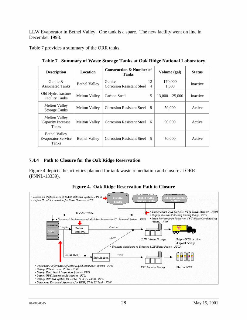
01-005-0515 28 May 15, 2001
LLW Evaporator in Bethel Valley. One tank is a spare. The new facility went on line in December 1998.
Table 7 provides a summary of the ORR tanks.
Table 7. Summary of Waste Storage Tanks at Oak Ridge National Laboratory
Description Location Construction & Number of Tanks Volume (gal) Status
Gunite & Associated Tanks Bethel Valley
Gunite 12 Corrosion Resistant Steel 4
170,000 1,500 Inactive
Old Hydrofracture Facility Tanks Melton Valley Carbon Steel 5 13,000 – 25,000 Inactive
Melton Valley Storage Tanks Melton Valley Corrosion Resistant Steel 8 50,000 Active
Melton Valley Capacity Increase
Tanks Melton Valley Corrosion Resistant Steel 6 90,000 Active
Bethel Valley Evaporator Service
Tanks Bethel Valley Corrosion Resistant Steel 5 50,000 Active
7.4.4 Path to Closure for the Oak Ridge Reservation
Figure 4 depicts the activities planned for tank waste remediation and closure at ORR (PNNL-13339).
Figure 4. Oak Ridge Reservation Path to Closure

01-005-0515 29 May 15, 2001
7.4.5 Regulatory Drivers for the Oak Ridge Reservation
The regulatory drivers for remediating ORR tank wastes are as follows:
• Federal Facility Agreement for ORR (DOE/OR-1014). This is an interagency agreement between EPA, DOE, and the Tennessee Department of Environment and Conservation. This agreement establishes requirements under the Comprehensive Environmental Response, Compensation, and Liability Act of 1980 for the management of tanks. Per this agreement, DOE must remove from service all tanks that operate without secondary containment. Tanks with secondary containment may continue to operate.
• Tennessee Department of Environment and Conservation Commissioner’s Order for ORR Site Treatment Plan. This requires that RCRA land disposal restricted waste must be treated for disposal per the agreed upon schedule.
• DOE Order 5820.2A requiring treatment of TRU waste for disposal at the Waste Isolation Pilot Plant
• Comprehensive Environmental Response, Compensation, and Liability Act of 1980
7.4.6 Milestones for the Oak Ridge Reservation
Selected ORR milestones are shown in Table 8.
Table 8. Oak Ridge Reservation Milestones
Milestone Title Completion Date
Complete Bethel Valley Remedial Action 2006
Complete White Oak Creek Remedial Action 2006
Complete legacy TRU waste treatment 2005
Complete legacy mixed and LLW treatment 2006
Complete Bethel Valley Remedial Action 2006
LLW = low-level waste. TRU = transuranic.

01-005-0515 30 May 15, 2001
8.0 PROPOSED WORK PLAN
8.1 GENERIC HIGH-LEVEL WASTE TANK LAY-UP ALTERNATIVES EVALUATION METHODOLOGY
8.1.1 Target Problem
Retrieval of HLW from underground storage tanks is underway throughout the DOE complex as a first step in the process of remediating the human health and environmental threat posed by the tank waste. The final step in this remediation process will be the closure of the tanks and tank farms. While there is a good deal of support for retrieval and treatment of the waste, there is some reluctance to establish final closure criteria for the tanks and move forward with tank closure, due in part to the finality of closure and the uncertainty associated with future impacts. As a result, each site will be faced with managing HLW storage tanks that are not quite empty for varying lengths of time after retrieval is complete until the tanks can be closed.
8.1.2 Work Element Descriptions
This task involves developing a methodology to support evaluation and selection of tank lay-up strategies for HLW tanks throughout the DOE complex. This methodology will focus on strategies for managing HLW tanks for the period of time between waste retrieval and tank closure. The methodology will be developed to allow consideration of tank-specific and site-specific issues.
Completion of this proposed scope of work will benefit all the sites by developing a common, demonstrated methodology for the transition from active storage to closure of the tanks.
8.1.2.1 Develop Functions and Requirements for Generic HLW Tank Lay-Up
Technical Description of Work:
Functions and requirements will be developed at a level of detail sufficient to support evaluations of the conceptual tank lay-up strategies developed for each site. The identification of functions and requirements will result in evaluation criteria to support the primary objective of placing the tanks in a safe, stable, and minimum maintenance mode that does not compromise final closure options.
Milestone:
Issue Generic HLW Tank Lay-Up Functions and Requirements
Description: Letter report to TFA summarizing tank lay-up system functions and requirements for the various DOE sites identifying the objectives of laying up the tanks, current tank conditions, and the tank lay-up system requirements.
01-005-0515 31 May 15, 2001
8.1.2.2 Develop Representative Lay-Up Strategies for Generic HLW Tanks
Technical Description of Work:
A list of representative tank lay-up strategies will be developed. The development of these strategies will include solicitation from the sites along with a search of outside sources to identify any new concepts that should be considered. These scenarios will be developed to a level of detail sufficient to support an evaluation using the criteria developed from the functions and requirements. It is anticipated that the tank lay-up strategies developed for WVDP will be used as a starting point for this activity.
One of the challenges expected in performing this task is laying out the methodology for moving tanks from the retrieval mode and into the tank lay-up mode. Jacobs is currently conducting a residual waste assessment of tank C-106 at Hanford, which was subjected to waste retrieval activities. The objective of the residual waste assessment is to evaluate options for the disposition of tank C-106 to support a decision on whether there is a need to retrieve additional waste or if the tank can be operationally closed (tank lay-up) pending final closure actions. Experience gained in evaluating regulatory, programmatic, and technical issues associated with lay-up of tank C-106 will be valuable in performing this task. Some of the difficulties in moving forward with tank lay-up strategies are the complexity of the closure criteria (which have not been fully defined) and less than ideal performance of waste retrieval systems. Waste retrieval systems typically leave some residual solids and liquid wastes behind that need to be considered in any tank lay-up strategy.
Milestone:
Issue Representative Generic HLW Tank Lay-Up Scenarios
Description: Letter report to TFA listing representative lay-up scenarios that have been reviewed and commented on by participants from other DOE sites and other appropriate sources
8.1.2.3 Develop Generic HLW Tank Lay-Up Decision Plan
Technical Description of Work:
Performance objectives and specific criteria will be developed to provide a means for evaluating tank lay-up strategies. The overall objective of the decision process will be to provide a technically defensible methodology for evaluating tank lay-up strategies. The decision criteria developed for WVDP under Part I will be used as a starting point for this task and expanded to cover the other sites. Examples of performance objectives or attributes that could be used include: minimize monitoring and maintenance cost, meet environmental regulations for operations, meet environmental regulations for tank closure, ensure nuclear safety, protect worker health and safety, and address stakeholder concerns. Specific criteria will then be developed for each of the performance objectives to the extent necessary to fully evaluate the objectives.
Scoring guidance will be developed for each criteria to support a quantitative comparison of the strategies. If determined to be necessary, a methodology will also be provided that will allow the
01-005-0515 32 May 15, 2001
decision makers to assign weighting factors to each of the decision criteria. Weighting factors will allow the decision makers the ability to identify the relative importance of the criteria to the decision.
A methodology for conducting a sensitivity analysis will be developed to validate that small changes would not significantly alter the final ranking of the strategies. The sensitivity analysis will be conducted after the ranking has been completed. The decision criteria along with scoring guidance will be documented for use by the sites in evaluating and selecting an approach for tank lay-up.
Milestone:
Issue Generic HLW Tank Lay-Up Decision Plan
Description: Letter report to TFA summarizing proposed decision criteria, scoring guidance, and sensitivity analysis methodology to be used for generic tank lay-up evaluations throughout the DOE complex
8.1.2.4 Evaluate Technical Concerns for Generic HLW Tanks
Technical Description of Work:
In parallel with development of representative lay-up strategies, technical areas of concern will be identified, prioritized, and addressed by subject matter experts. The technical concerns identified for WVDP will be used as a starting point and will be expanded to cover technical concerns for the other sites. These technical concern areas will be reviewed and prioritized with site representatives and the TFA Technical Integration Manager for Safety relative to their impact on the identified lay-up strategies. Subject matter experts will evaluate a select number of the higher priority technical concerns to the extent necessary to factor the concerns into the decision criteria process. It is envisioned that subject matter experts will be tasked with developing white papers to address the specific technical areas of concern. These white papers will then be incorporated into the description of tank lay-up scenarios.
The primary areas of technical concern that have been identified include tank integrity and corrosion issues. Additional areas of technical concern include, but are not limited to, identification and evaluation of stabilization materials, tank monitoring requirements, retrieval/closure criteria, and regulatory analysis.
Milestones:
No milestones associated with this work element. Output from this work element will be included in the description of tank lay-up scenarios and in the final report for the project.
01-005-0515 33 May 15, 2001
8.1.2.5 Perform Demonstration of Generic HLW Tank Lay-Up Evaluation Methodology
Technical Description of Work:
A demonstration of the tank lay-up evaluation methodology will be conducted using site and tank-specific information for one tank. The purpose of the demonstration will be to apply the methodology to a specific tank in order to evaluate the methodology as a “value-added” tool to support individual site evaluation and selection of strategies for tank lay-up. Following the demonstration, the methodology will be incorporated into an interactive program for evaluating and documenting the tank lay-up evaluations. It is envisioned that this program will facilitate the application of the tank lay-up methodology by reducing the end user’s need to rely on the written reports for definition and guidance for applying the methodology.
Milestones:
Demonstrate Generic HLW Tank Lay-Up Alternatives Evaluation Methodology
Description: Letter report to TFA summarizing the application of the evaluation methodology to a selected tank at one site
Issue Final Report For Generic HLW Tank Lay-Up Alternatives Evaluation Methodology
Description: Final report to TFA describing and documenting the evaluation methodology developed under this task to aid individual sites in evaluating and selecting strategies for tank lay-up
9.0 REFERENCES
60 FR 18589, 1995, “Record of Decision for the Defense Waste Processing Facility at the Savannah River Site, Aiken, South Carolina,” Federal Register, April 12.
60 FR 55249, 1995, “Record of Decision for Savannah River Site Waste Management,” Federal Register, October 30.
62 FR 8693, 1997, “Record of Decision for the Tank Waste Remediation System, Hanford Site, Richland, Washington,” Federal Register, February 26.
64 FR 61615, 1999, “Record of Decision for the Hanford Comprehensive Land-Use Plan Environmental Impact Statement, Federal Register, November 12, 1999.
BBI, 2001, Best Basis Inventory, access page located at http://twins.pnl.gov:8001/twins.htm, as of May 2001.
Cory, W. N., 1998, “Second Modification to Consent Order,” Idaho Department of Health and Welfare, Division of Environmental Quality, Boise, Idaho.
01-005-0515 34 May 15, 2001
DOE/EIS-0082S, 1994, Final Environmental Impact Statement - Defense Waste Processing Facility, U.S. Department of Energy, Savannah River Operations Office, Aiken, South Carolina.
DOE/EIS-0189, 1996, Final Environmental Impact Statement for the Tank Waste Remediation System, U.S. Department of Energy, Richland Operations Office, Richland, Washington.
DOE/EIS-0217, 1995, Savannah River Site, Waste Management, Final Environmental Impact Statement, 2 volumes, U.S. Department of Energy Savannah River Operations Office, Aiken, South Carolina.
DOE/EIS-0222F, 1999, Final Hanford Comprehensive Land Use Plan Environmental Impact Statement, U.S. Department of Energy, Richland Operations Office, Richland, Washington.
DOE/EIS-0303D, 2000, High Level Waste Tank Closure, Draft Environmental Impact Statement, U.S. Department of Energy, Savannah River Operations Office, Aiken, South Carolina.
DOE/EIS-0287D, 1999, Idaho High-Level Waste and Facilities Disposition Draft Environmental Impact Statement, U.S. Department of Energy.
DOE/EM-0362, 1998, Accelerating Cleanup: Paths to Closure, U.S. Department of Energy, Washington, D.C.
DOE O 435.1, 1997, Radioactive Waste Management, U.S. Department of Energy, Washington, D.C.
DOE/OR-1014, 1992, Federal Facility Agreement for the Oak Ridge Reservation, U.S. Department of Energy Oak Ridge Operations Office, Environmental Protection Agency, and the Tennessee Department of Environmental and Conservation, U.S. Department of Energy, Oak Ridge Operations Office, Oak Ridge, Tennessee.
DOE/RL-00-01, 1994, Recommendation 93-5 Implementation Plan, U.S. Department of Energy, Richland Operations Office, Richland, Washington.
DOE/RL-97-57, Draft, Accelerating Cleanup Paths to Closure Hanford Site, U.S. Department of Energy, Richland Operations Office, Richland, Washington.
DOE/RL-89-16, 2001, Single-Shell Tank Closure Work Plan (Draft), Jacobs Engineering Group Inc., Richland, Washington
Ecology, EPA, and DOE, 1989, Hanford Federal Facilities Agreement and Consent Order, as amended, Washington State Department of Ecology, U.S. Environmental Protection Agency, U.S. Department of Energy, Olympia, Washington.
Federal Facility Compliance Act of 1992, Public Law 102-386, 42 USC 6921 et seq.
01-005-0515 35 May 15, 2001
HLW-TEC-950027, 1995, FY-96 High-level Waste Management Technology Program Plan, Westinghouse Savannah River Company, Aiken, South Carolina.
HNF-EP-0182-155, 2001, Waste Tank Summary Report for Month Ending February 28, 2001, CH2MHILL Hanford Group, Inc., Richland, Washington.
Kelly, K. B., 1999, “Third Modification to Consent Order” (letter to B. Bowhan, U.S. Department of Energy, Idaho Operations Office), State of Idaho, Office of Attorney General, Boise, Idaho.
MOU, 1996, Memorandum of Understanding: Required Percent of Waste Retrieval, U.S. Department of Energy and Washington State Department of Ecology, Richland, Washington.
PNNL-13339, 1999, Tanks Focus Area Multiyear Program Plan FY01-FY05, Pacific Northwest National Laboratory, Richland, Washington.
WHC-EP-0566, 1993, Underground Storage Tank-integrated Demonstration Participant Site Characteristic Summary, Westinghouse Hanford Company, Richland, Washington.