Embed Size (px)
Citation preview
8/3/2019 Post ESP Guidelines
http://slidepdf.com/reader/full/post-esp-guidelines 1/26
RECOMMENDED GOOD PRACTICE
GUIDELINES FOR
POST-ESP PROCEDURES
FOR
BLACK LIQUOR RECOVERY BOILERS
THE BLACK LIQUOR RECOVERY BOILER ADVISORY COMMITTEE
October 2002
8/3/2019 Post ESP Guidelines
http://slidepdf.com/reader/full/post-esp-guidelines 2/26
BLRBAC RECOMMENDED GOOD PRACTICE
Recommended Post-ESP Procedure for Black Liquor Recovery Boilers
Page 2
Table of Contents
FOREWARD................................................................................................................................................. 4
CHANGES..................................................................................................................................................... 5
CHAPTER 1 VERIFICATION OF ESP FUNCTIONS............................................................................6
CHAPTER 2 OPERATING PROCEDURES ............................................................................................ 7
2.1 EVACUATION ........................................................................................................................................7 2.2 FAILURE OF ESP FUNCTIONS ................................................................................................................7 2.3 CONTROL OF ACCESS ............................................................................................................................7 2.4 CLOSING R EMOTE ISOLATION VALVES ................................................................................................. 7 2.5 NOTIFICATION.......................................................................................................................................7 2.6 ADJACENT EQUIPMENT .........................................................................................................................8 2.7 LOWER FURNACE WATER LEVEL..........................................................................................................8 2.8 OPERATING DATA COLLECTION............................................................................................................8
CHAPTER 3 OPERATOR INTERVIEWS................................................................................................9
CHAPTER 4 ESP SYSTEM RESET ........................................................................................................ 10
CHAPTER 5 ESP RE-ENTRY WAITING PERIOD.............................................................................. 11
5.1 FIXED TIME PERIOD ............................................................................................................................11 5.2 CONDITION BASED R ULES .................................................................................................................. 11
CHAPTER 6 RE-ENTRY INTO RECOVERY BOILER AREA...........................................................13
CHAPTER 7 CONDITION ASSESSMENT ............................................................................................14
CHAPTER 8 CHAR BED COOL-DOWN...............................................................................................15
CHAPTER 9 WATER WASHING ...........................................................................................................16
CHAPTER 10 FLOOR INSPECTION..................................................................................................... 17
CHAPTER 11 CHECK OF DRUM INTERNALS ..................................................................................18
CHAPTER 12 HYDROSTATIC TESTS.................................................................................................. 19
APPENDIX A RECOVERY BOILER EXPLOSION HISTORY.......................................................... 20
APPENDIX B DOCUMENT REVISION HISTORY.............................................................................. 26
Table of Tables
TABLE 1. R ECOVERY BOILER EXPLOSION HISTORY ...................................................................................... 21 TABLE 2. EXPLOSIONS FROM PRESSURE PART FAILURE ................................................................................22 TABLE 3. WATER SOURCES FOR SMELT-WATER EXPLOSIONS (1970 – 1993) ............................................... 23 TABLE 4. TIME DELAYS IN SMELT-WATER EXPLOSIONS ...............................................................................24 TABLE 5. CATEGORIES OF I NCIDENTS ............................................................................................................25

8/3/2019 Post ESP Guidelines
http://slidepdf.com/reader/full/post-esp-guidelines 3/26
BLRBAC RECOMMENDED GOOD PRACTICE
Recommended Post-ESP Procedure for Black Liquor Recovery Boilers
Page 3
8/3/2019 Post ESP Guidelines
http://slidepdf.com/reader/full/post-esp-guidelines 4/26
BLRBAC RECOMMENDED GOOD PRACTICE
Recommended Post-ESP Procedure for Black Liquor Recovery Boilers
Page 4
FOREWARD
The activities that take place following initiation of an Emergency Shutdown Procedure
(ESP) on a black liquor recovery boiler can have a significant impact on personnel safety,
equipment protection, and down time. The following guidelines are intended to identifythe essential elements of a Post-ESP Procedure. It is the responsibility of each operating
company to use these guidelines to develop a comprehensive set of site-specific
procedures covering post-ESP activities. These guidelines are intended to cover situationswhen there has not been an explosion. In the event that an explosion occurs prior to,
during, or following an ESP, the post-ESP procedures may have to be altered to deal with
emergency situations.
This guideline reflects nomenclature and functions of current system installation and
industry practice. This document should not be used to interpret BLRBAC system
design recommendations. For detailed ESP system recommendations refer to BLRBAC
document “Emergency Shutdown Procedure (ESP) and Procedure for Testing ESPSystem for Black Liquor Recovery Boilers”.

8/3/2019 Post ESP Guidelines
http://slidepdf.com/reader/full/post-esp-guidelines 5/26
BLRBAC RECOMMENDED GOOD PRACTICE
Recommended Post-ESP Procedure for Black Liquor Recovery Boilers
Page 5
CHANGES
There are no changes. This is the initial issue of this document.
8/3/2019 Post ESP Guidelines
http://slidepdf.com/reader/full/post-esp-guidelines 6/26
BLRBAC RECOMMENDED GOOD PRACTICE
Recommended Post-ESP Procedure for Black Liquor Recovery Boilers
Page 6
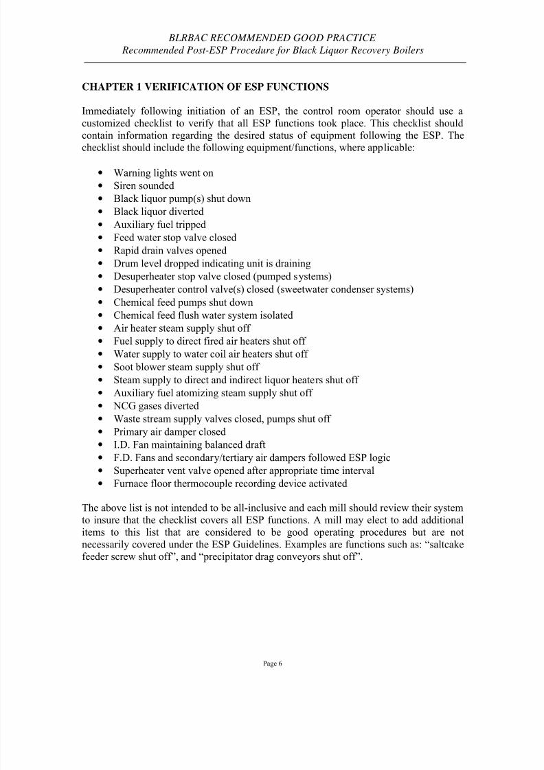
CHAPTER 1 VERIFICATION OF ESP FUNCTIONS
Immediately following initiation of an ESP, the control room operator should use a
customized checklist to verify that all ESP functions took place. This checklist should
contain information regarding the desired status of equipment following the ESP. Thechecklist should include the following equipment/functions, where applicable:
• Warning lights went on
• Siren sounded
• Black liquor pump(s) shut down
• Black liquor diverted
• Auxiliary fuel tripped
• Feed water stop valve closed
• Rapid drain valves opened
• Drum level dropped indicating unit is draining
• Desuperheater stop valve closed (pumped systems)
• Desuperheater control valve(s) closed (sweetwater condenser systems)
• Chemical feed pumps shut down
• Chemical feed flush water system isolated
• Air heater steam supply shut off
• Fuel supply to direct fired air heaters shut off
• Water supply to water coil air heaters shut off
• Soot blower steam supply shut off
• Steam supply to direct and indirect liquor heaters shut off
• Auxiliary fuel atomizing steam supply shut off
• NCG gases diverted• Waste stream supply valves closed, pumps shut off
• Primary air damper closed
• I.D. Fan maintaining balanced draft
• F.D. Fans and secondary/tertiary air dampers followed ESP logic
• Superheater vent valve opened after appropriate time interval
• Furnace floor thermocouple recording device activated
The above list is not intended to be all-inclusive and each mill should review their systemto insure that the checklist covers all ESP functions. A mill may elect to add additional
items to this list that are considered to be good operating procedures but are not
necessarily covered under the ESP Guidelines. Examples are functions such as: “saltcakefeeder screw shut off”, and “precipitator drag conveyors shut off”.
8/3/2019 Post ESP Guidelines
http://slidepdf.com/reader/full/post-esp-guidelines 7/26
BLRBAC RECOMMENDED GOOD PRACTICE
Recommended Post-ESP Procedure for Black Liquor Recovery Boilers
Page 7
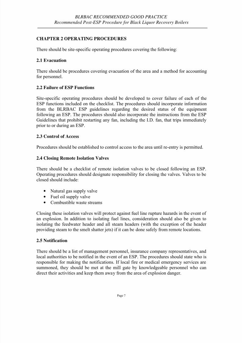
CHAPTER 2 OPERATING PROCEDURES
There should be site-specific operating procedures covering the following:
2.1 Evacuation
There should be procedures covering evacuation of the area and a method for accounting
for personnel.
2.2 Failure of ESP Functions
Site-specific operating procedures should be developed to cover failure of each of the
ESP functions included on the checklist. The procedures should incorporate information
from the BLRBAC ESP guidelines regarding the desired status of the equipmentfollowing an ESP. The procedures should also incorporate the instructions from the ESP
Guidelines that prohibit restarting any fan, including the I.D. fan, that trips immediately prior to or during an ESP.
2.3 Control of Access
Procedures should be established to control access to the area until re-entry is permitted.
2.4 Closing Remote Isolation Valves
There should be a checklist of remote isolation valves to be closed following an ESP.
Operating procedures should designate responsibility for closing the valves. Valves to be
closed should include:
• Natural gas supply valve
• Fuel oil supply valve
• Combustible waste streams
Closing these isolation valves will protect against fuel line rupture hazards in the event of
an explosion. In addition to isolating fuel lines, consideration should also be given to
isolating the feedwater header and all steam headers (with the exception of the header providing steam to the smelt shatter jets) if it can be done safely from remote locations.
2.5 Notification
There should be a list of management personnel, insurance company representatives, and
local authorities to be notified in the event of an ESP. The procedures should state who isresponsible for making the notifications. If local fire or medical emergency services are
summoned, they should be met at the mill gate by knowledgeable personnel who can
direct their activities and keep them away from the area of explosion danger.
8/3/2019 Post ESP Guidelines
http://slidepdf.com/reader/full/post-esp-guidelines 8/26
BLRBAC RECOMMENDED GOOD PRACTICE
Recommended Post-ESP Procedure for Black Liquor Recovery Boilers
Page 8
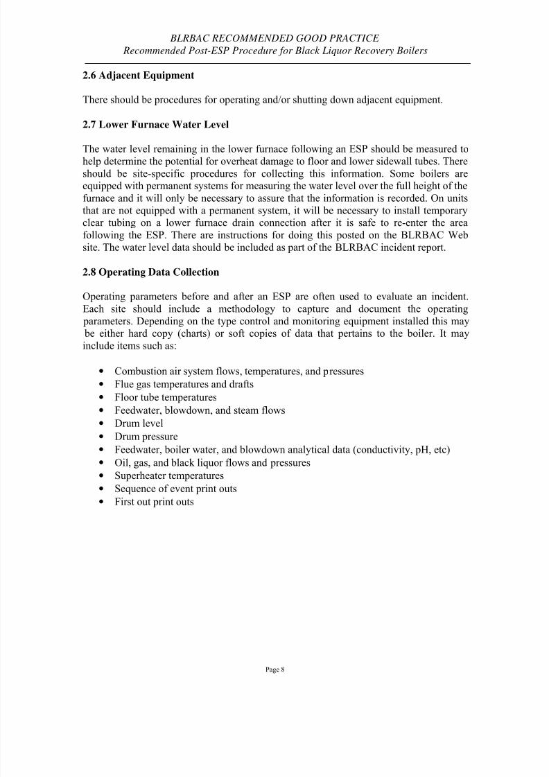
2.6 Adjacent Equipment
There should be procedures for operating and/or shutting down adjacent equipment.
2.7 Lower Furnace Water Level
The water level remaining in the lower furnace following an ESP should be measured to
help determine the potential for overheat damage to floor and lower sidewall tubes. There
should be site-specific procedures for collecting this information. Some boilers areequipped with permanent systems for measuring the water level over the full height of the
furnace and it will only be necessary to assure that the information is recorded. On units
that are not equipped with a permanent system, it will be necessary to install temporaryclear tubing on a lower furnace drain connection after it is safe to re-enter the area
following the ESP. There are instructions for doing this posted on the BLRBAC Web
site. The water level data should be included as part of the BLRBAC incident report.
2.8 Operating Data Collection
Operating parameters before and after an ESP are often used to evaluate an incident.
Each site should include a methodology to capture and document the operating
parameters. Depending on the type control and monitoring equipment installed this may be either hard copy (charts) or soft copies of data that pertains to the boiler. It may
include items such as:
• Combustion air system flows, temperatures, and pressures
• Flue gas temperatures and drafts
• Floor tube temperatures
• Feedwater, blowdown, and steam flows• Drum level
• Drum pressure
• Feedwater, boiler water, and blowdown analytical data (conductivity, pH, etc)
• Oil, gas, and black liquor flows and pressures
• Superheater temperatures
• Sequence of event print outs
• First out print outs
8/3/2019 Post ESP Guidelines
http://slidepdf.com/reader/full/post-esp-guidelines 9/26
BLRBAC RECOMMENDED GOOD PRACTICE
Recommended Post-ESP Procedure for Black Liquor Recovery Boilers
Page 9
CHAPTER 3 OPERATOR INTERVIEWS
All operators on duty at the time of the ESP should be interviewed before leaving the mill
to assure all information relating to the ESP is available for making subsequent decisions.
The interview should include:
• Events and/or conditions that led to the decision to ESP
• Any problems encountered during or following the ESP
8/3/2019 Post ESP Guidelines
http://slidepdf.com/reader/full/post-esp-guidelines 10/26
BLRBAC RECOMMENDED GOOD PRACTICE
Recommended Post-ESP Procedure for Black Liquor Recovery Boilers
Page 10
CHAPTER 4 ESP SYSTEM RESET
The ESP system should not be reset until re-entry into the area is permitted. The ESP
system reset logic/procedures may result in automatic movement of controls to undesired
positions. Proper caution should be taken to position controls where intended. Examplesof valves that may need isolation or manual positioning prior to reset include the
feedwater to the economizer and the steam to the steam coil air heater(s).
The audible ESP alarm should be silenced after sounding for a minimum of 15 minutes if
it is a distraction to operating personnel and impedes communications. Procedures to
control access to the area should be in effect prior to silencing the alarm. Silencing thealarm should be completely independent of the ESP system reset. Visual alarms are to
remain in effect until the ESP system is reset.
8/3/2019 Post ESP Guidelines
http://slidepdf.com/reader/full/post-esp-guidelines 11/26
BLRBAC RECOMMENDED GOOD PRACTICE
Recommended Post-ESP Procedure for Black Liquor Recovery Boilers
Page 11
CHAPTER 5 ESP RE-ENTRY WAITING PERIOD
Post-ESP procedures should include rules covering the length of the waiting period for
re-entry into the recovery boiler area following an ESP (no explosion). BLRBAC has not
set a minimum waiting period and has left this decision to the operating companies. Atthe fall 1993 BLRBAC Meeting, a paper was presented summarizing BLRBAC recovery
boiler explosion history including data on the time interval from water entry into the
furnace until explosion. (See Appendix A) This information can be used as the basis for establishing a safe waiting period.
The industry currently utilizes two types of rules – fixed time periods and condition based.
5.1 Fixed Time Period
A number of companies set a fixed time period that personnel must remain outside the building following an ESP.
5.2 Condition Based Rules
With condition-based rules, the information available to operating personnel is used to
determine the minimum-waiting period that personnel must remain outside the area
following an ESP. The following conditions should be considered when determining the
waiting period:
• Location of leak (Water could / could not enter the furnace.)
• Size of leak (Large / Small) • Was the boiler successfully ESP’d? (Yes / No)
• Evidence of floor tube damage resulting from the ESP (Yes / No)
Use of condition-based rules will require establishing a minimum waiting period for each
of the possible combinations of conditions listed above. Procedures should designate whois responsible for making the decision regarding the waiting period.
Example 1: After the boiler was ESP’d, it was determined that there was a small leak in
the economizer (no possibility of water entering the furnace), the boiler was successfullyESP’d and there was no evidence of floor tube damage from the ESP. These conditions
would require minimal waiting time before re-entering the building.
Example 2: After the boiler was ESP’d, it was determined that there was a large leak in
the lower furnace, the boiler did not drain, and there was no evidence of damage to the
floor due to the ESP. These conditions would require maximum waiting time before re-entering the area.

8/3/2019 Post ESP Guidelines
http://slidepdf.com/reader/full/post-esp-guidelines 12/26
BLRBAC RECOMMENDED GOOD PRACTICE
Recommended Post-ESP Procedure for Black Liquor Recovery Boilers
Page 12
Inadequate Information. If any of the information required to make a decision is not
available or the accuracy is questionable, the worst conditions should be assumed and themaximum waiting period should be used.

8/3/2019 Post ESP Guidelines
http://slidepdf.com/reader/full/post-esp-guidelines 13/26
BLRBAC RECOMMENDED GOOD PRACTICE
Recommended Post-ESP Procedure for Black Liquor Recovery Boilers
Page 13
CHAPTER 6 RE-ENTRY INTO RECOVERY BOILER AREA
Once the waiting period has expired, one or two qualified personnel should enter the
recovery building to determine if there are any conditions that require extending the
waiting period. If there are not, then required operating and maintenance personnel can be allowed back into the area.
If there is any evidence of accumulation of water on the bed, operating and maintenance personnel should be kept out of the area until all indications of any hot spots in the bed
are gone. The surface of the bed fractures as it cools and the potential exists for
accumulated water to enter one of these fractures and cause a smelt water explosion.
8/3/2019 Post ESP Guidelines
http://slidepdf.com/reader/full/post-esp-guidelines 14/26
BLRBAC RECOMMENDED GOOD PRACTICE
Recommended Post-ESP Procedure for Black Liquor Recovery Boilers
Page 14
CHAPTER 7 CONDITION ASSESSMENT
After re-entry into the area, it will be necessary to assess the condition of the boiler to
determine what steps are required to make repairs and get the boiler ready to return to
operation. This assessment should include the following:
• Assessment of the condition of the char bed and determination of whether supplemental bed cooling will be used
• Determination of whether it will be necessary to water wash
• Determination of whether a hydrostatic test will be required to locate the leak
• Identification of the location of the leak and extent of damage
• Evaluation of floor thermocouple data and any information regarding lower furnace water level to determine if the floor boiled dry and the potential for floor tube damage
The normal sequence of events following condition assessment will be:
• Char bed cool-down
• Probing bed to check for hot spots
• Water washing
• Hydrostatic test for determination of leak location
• Leak repair
• Floor cleaning and inspection
• Final hydrostatic test
8/3/2019 Post ESP Guidelines
http://slidepdf.com/reader/full/post-esp-guidelines 15/26
BLRBAC RECOMMENDED GOOD PRACTICE
Recommended Post-ESP Procedure for Black Liquor Recovery Boilers
Page 15
CHAPTER 8 CHAR BED COOL-DOWN
Before the furnace can be water-washed or hydrostatically tested, it is necessary to
determine that the char bed / smelt pool has cooled sufficiently to ensure that there is no
longer the possibility that molten smelt is present. A char bed is highly insulating and pockets of molten smelt can exist in a large bed for several days after an ESP. Before the
furnace can be water-washed, the bed should be probed with thermocouples to make
certain that no hot spots remain that could contain molten smelt. A hard crust willnormally form on the surface of the bed and some hand lancing will usually be necessary
to break up the crust to allow checking subsurface material for hot spots. Under no
circumstances should water washing begin if there are any visible, glowing hot spots present in the char bed.
The char bed can be allowed to cool on its own or it can be broken up and cooled downusing hand lances to inject a cooling medium such as nitrogen propelled sodium
bicarbonate, liquid carbon dioxide, or low pressure dry steam. The use of hand lanceswith cooling medium facilitates break-up of the bed crust - disrupting the bed andexposing hot material to the cooling medium. In addition to significantly reducing the
cool down time, breaking up the bed makes it much easier to probe the bed with
thermocouples and determine that all hot spots have been eliminated. Under nocircumstances should water - including “fog” nozzles - be used for bed cooling.
Each mill should have a written char bed cool-down procedure that includes the
following:
Procedures for use of bed cooling mediums such as sodium bicarbonate, liquid carbon
dioxide or low-pressure steam (if they are to be used). If low-pressure steam is to be used,the procedures need to include provisions to prevent any condensate from entering the
furnace.
• Type of thermocouple equipment and procedures to be used for probing the bed tocheck for hot spots.
• Maximum bed temperature allowable to start water washing in the furnace. For units with hearth designs that retain a residual pool of smelt, the procedures mayalso include a minimum time interval before water washing can commence.
The melting temperature for smelt is normally around 1400° F but it can be as low as
1000° F depending on the chemistry. The maximum bed temperature allowable to startwater washing should provide enough safety-margin to take into account potential
variations in smelt chemistry, the potential for localized hot spots, and the inability to
probe 100% of the bed. The maximum bed temperature used by the majority of
companies that provided input for these guidelines is 800° F.
8/3/2019 Post ESP Guidelines
http://slidepdf.com/reader/full/post-esp-guidelines 16/26
BLRBAC RECOMMENDED GOOD PRACTICE
Recommended Post-ESP Procedure for Black Liquor Recovery Boilers
Page 16
CHAPTER 9 WATER WASHING
Following completion of cool down of the bed including any minimum time interval
requirements, water washing of the furnace can begin using the mill’s normal water wash
procedures. These procedures should include the following:
• The differential between wash water temperature and pressure part metaltemperatures does not exceed manufacturer’s recommendations
• An adequate number of smelt spouts are open to drain wash water
• Procedures to protect personnel from burn hazard due to exposure to hot water
• Procedures to prevent flooding and collapse of flues, ducts, hoppers, etc. due to
plugged drain lines or openings
As an additional precaution, consideration should be given to having all but essential
personnel leave the area for a pre-established period of time starting prior to the
introduction of wash water into the furnace.

8/3/2019 Post ESP Guidelines
http://slidepdf.com/reader/full/post-esp-guidelines 17/26
BLRBAC RECOMMENDED GOOD PRACTICE
Recommended Post-ESP Procedure for Black Liquor Recovery Boilers
Page 17
CHAPTER 10 FLOOR INSPECTION
The floor thermocouple data and any information regarding lower furnace water level
should be evaluated to determine if the floor boiled dry and the potential for floor tube
damage. If there is evidence of potential damage, then the floor should be cleaned andinspected prior to starting back up.

8/3/2019 Post ESP Guidelines
http://slidepdf.com/reader/full/post-esp-guidelines 18/26
BLRBAC RECOMMENDED GOOD PRACTICE
Recommended Post-ESP Procedure for Black Liquor Recovery Boilers
Page 18
CHAPTER 11 CHECK OF DRUM INTERNALS
There have been several reports of loose drum internals found after an ESP. Drum
internals should be checked prior to putting the boiler back in service.

8/3/2019 Post ESP Guidelines
http://slidepdf.com/reader/full/post-esp-guidelines 19/26
BLRBAC RECOMMENDED GOOD PRACTICE
Recommended Post-ESP Procedure for Black Liquor Recovery Boilers
Page 19
CHAPTER 12 HYDROSTATIC TESTS
A final hydrostatic test should be conducted following completion of repairs and
inspection of the unit. The ESP procedure subjects the boiler to significant thermal
stresses so the boiler should be thoroughly inspected for any resultant damage. In anumber of cases, leaking generating bank tube seats were found in two-drum recovery
boilers following an ESP, so the generating bank should be carefully inspected for leaks.
8/3/2019 Post ESP Guidelines
http://slidepdf.com/reader/full/post-esp-guidelines 20/26
BLRBAC RECOMMENDED GOOD PRACTICE
Recommended Post-ESP Procedure for Black Liquor Recovery Boilers
Page 20
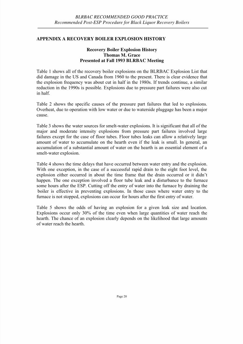
APPENDIX A RECOVERY BOILER EXPLOSION HISTORY
Recovery Boiler Explosion History
Thomas M. Grace
Presented at Fall 1993 BLRBAC Meeting
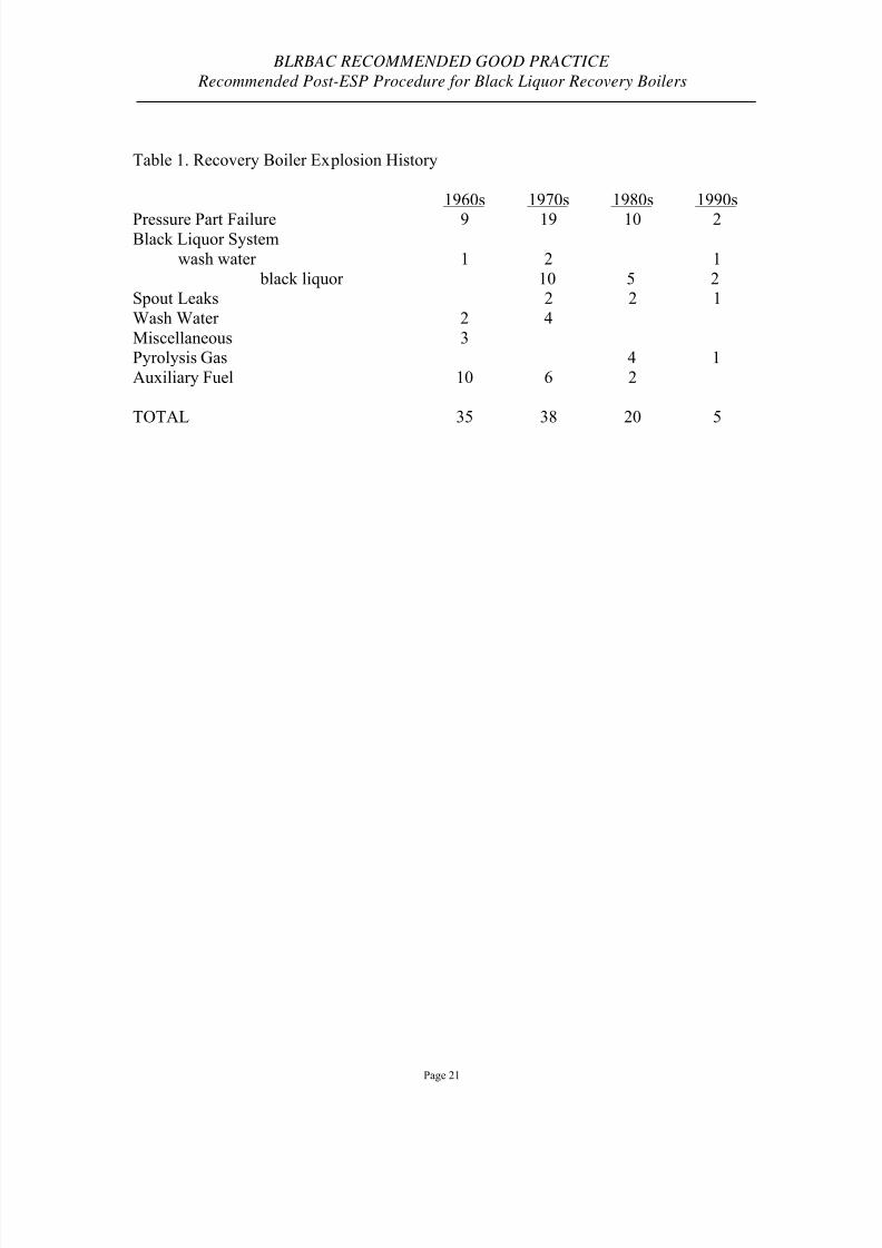
Table 1 shows all of the recovery boiler explosions on the BLRBAC Explosion List that
did damage in the US and Canada from 1960 to the present. There is clear evidence thatthe explosion frequency was about cut in half in the 1980s. If trends continue, a similar
reduction in the 1990s is possible. Explosions due to pressure part failures were also cut
in half.
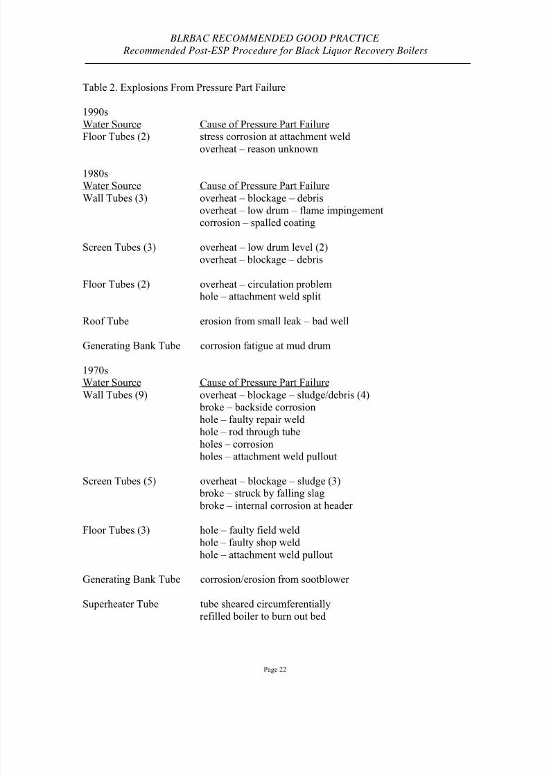
Table 2 shows the specific causes of the pressure part failures that led to explosions.
Overheat, due to operation with low water or due to waterside pluggage has been a major cause.
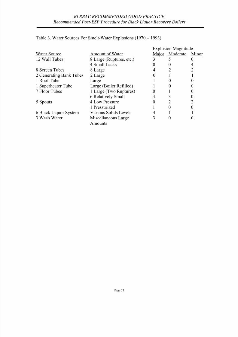
Table 3 shows the water sources for smelt-water explosions. It is significant that all of themajor and moderate intensity explosions from pressure part failures involved large
failures except for the case of floor tubes. Floor tubes leaks can allow a relatively large
amount of water to accumulate on the hearth even if the leak is small. In general, anaccumulation of a substantial amount of water on the hearth is an essential element of a
smelt-water explosion.
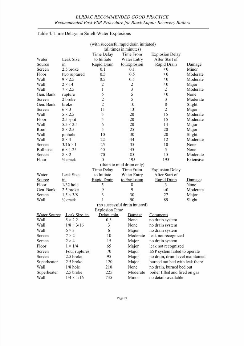
Table 4 shows the time delays that have occurred between water entry and the explosion.With one exception, in the case of a successful rapid drain to the eight foot level, the
explosion either occurred in about the time frame that the drain occurred or it didn’t
happen. The one exception involved a floor tube leak and a disturbance to the furnacesome hours after the ESP. Cutting off the entry of water into the furnace by draining the
boiler is effective in preventing explosions. In those cases where water entry to the
furnace is not stopped, explosions can occur for hours after the first entry of water.
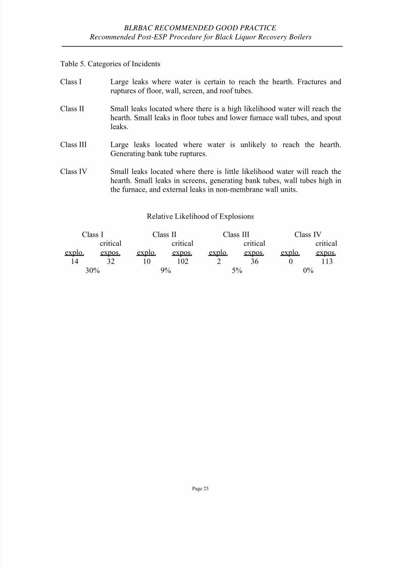
Table 5 shows the odds of having an explosion for a given leak size and location.
Explosions occur only 30% of the time even when large quantities of water reach thehearth. The chance of an explosion clearly depends on the likelihood that large amounts
of water reach the hearth.
8/3/2019 Post ESP Guidelines
http://slidepdf.com/reader/full/post-esp-guidelines 21/26
BLRBAC RECOMMENDED GOOD PRACTICE
Recommended Post-ESP Procedure for Black Liquor Recovery Boilers
Page 21
Table 1. Recovery Boiler Explosion History
1960s 1970s 1980s 1990s
Pressure Part Failure 9 19 10 2Black Liquor System
wash water 1 2 1
black liquor 10 5 2Spout Leaks 2 2 1
Wash Water 2 4
Miscellaneous 3Pyrolysis Gas 4 1
Auxiliary Fuel 10 6 2
TOTAL 35 38 20 5
8/3/2019 Post ESP Guidelines
http://slidepdf.com/reader/full/post-esp-guidelines 22/26
BLRBAC RECOMMENDED GOOD PRACTICE
Recommended Post-ESP Procedure for Black Liquor Recovery Boilers
Page 22
Table 2. Explosions From Pressure Part Failure
1990s
Water Source Cause of Pressure Part Failure
Floor Tubes (2) stress corrosion at attachment weldoverheat – reason unknown
1980sWater Source Cause of Pressure Part Failure
Wall Tubes (3) overheat – blockage – debris
overheat – low drum – flame impingementcorrosion – spalled coating
Screen Tubes (3) overheat – low drum level (2)overheat – blockage – debris
Floor Tubes (2) overheat – circulation problemhole – attachment weld split
Roof Tube erosion from small leak – bad well
Generating Bank Tube corrosion fatigue at mud drum
1970sWater Source Cause of Pressure Part Failure
Wall Tubes (9) overheat – blockage – sludge/debris (4)
broke – backside corrosionhole – faulty repair weld
hole – rod through tube
holes – corrosionholes – attachment weld pullout
Screen Tubes (5) overheat – blockage – sludge (3) broke – struck by falling slag
broke – internal corrosion at header
Floor Tubes (3) hole – faulty field weld
hole – faulty shop weldhole – attachment weld pullout
Generating Bank Tube corrosion/erosion from sootblower
Superheater Tube tube sheared circumferentiallyrefilled boiler to burn out bed
8/3/2019 Post ESP Guidelines
http://slidepdf.com/reader/full/post-esp-guidelines 23/26
BLRBAC RECOMMENDED GOOD PRACTICE
Recommended Post-ESP Procedure for Black Liquor Recovery Boilers
Page 23
Table 3. Water Sources For Smelt-Water Explosions (1970 – 1993)
Explosion Magnitude
Water Source Amount of Water Major Moderate Minor
8 Large (Ruptures, etc.) 3 5 012 Wall Tubes4 Small Leaks 0 0 4
8 Screen Tubes 8 Large 4 2 2
2 Generating Bank Tubes 2 Large 0 1 11 Roof Tube Large 1 0 0
1 Superheater Tube Large (Boiler Refilled) 1 0 0
1 Large (Two Ruptures) 0 1 07 Floor Tubes6 Relatively Small 3 3 0
4 Low Pressure 0 2 25 Spouts
1 Pressurized 1 0 06 Black Liquor System Various Solids Levels 4 1 1
Miscellaneous Large 3 0 03 Wash Water Amounts
8/3/2019 Post ESP Guidelines
http://slidepdf.com/reader/full/post-esp-guidelines 24/26
BLRBAC RECOMMENDED GOOD PRACTICE
Recommended Post-ESP Procedure for Black Liquor Recovery Boilers
Page 24
Table 4. Time Delays in Smelt-Water Explosions
(with successful rapid drain initiated)(all times in minutes)
Water Source Leak Size,in.
Time Delay
to InitiateRapid Drain
Time From
Water Entryto Explosion
Explosion Delay
After Start of Rapid Drain DamageScreen 2.5 broke 0.1 0.1 ≈0 Minor Floor two ruptured 0.5 0.5 ≈0 Moderate
Wall 9 × 2.5 0.5 0.5 ≈0 ModerateWall 2 × 14 2 2 ≈0 Major Wall 7 × 2.5 1 3 2 ModerateGen. Bank rupture 5 5 ≈0 NoneScreen 2 broke 2 5 3 Moderate
Gen. Bank broke 2 10 8 SlightScreen 6 × 3 11 13 2 Major Wall 5 × 2.5 5 20 15 Moderate
Floor 2.5 split 5 20 15 ModerateWall 5.5 × 2.5 6 20 14 Major
Roof 8 × 2.5 5 25 20 Major Wall pinhole 10 30 20 SlightWall 8 × 3 22 34 12 ModerateScreen 3/16 × 1 25 35 10 None
Bullnose 6 × 1.25 40 45 5 NoneScreen 8 × 2 70 85 15 ModerateFloor ½ crack 0 195 195 Extensive
(drain to mud drum only)
Water
Source
Leak Size,
in.
Time Delay
to Initiate
Rapid Drain
Time From
Water Entry
to Explosion
Explosion Delay
After Start of
Rapid Drain DamageFloor 1/32 hole 5 8 3 NoneGen. Bank 2.5 broke 9 9 ≈0 ModerateScreen 1.5 × 3/8 3 30 27 Major
Wall ½ crack 1 90 89 Slight(no successful drain intiated)
Water Source Leak Size, in.Explosion Time
Delay, min. Damage CommentsWall 5 × 2.2 0.5 None no drain system
Wall 1/8 × 3/16 3 None no drain system
Wall 6 × 3 6 Major no drain system
Screen 7 × 2 10 Moderate leak not recognized
Screen 2 × 4 15 Major no drain systemFloor 1 × 1/4 65 Major leak not recognized
Screen Four ruptures 70 Major ESP system failed to operate
Screen 2.5 broke 95 Major no drain, drum level maintained
Superheater 2.5 broke 120 Major burned out bed with leak there
Wall 1/8 hole 210 None no drain, burned bed out
Superheater 2.5 broke 225 Moderate boiler filled and fired on gas
Wall 1/4 × 1/16 735 Minor no details available
8/3/2019 Post ESP Guidelines
http://slidepdf.com/reader/full/post-esp-guidelines 25/26
BLRBAC RECOMMENDED GOOD PRACTICE
Recommended Post-ESP Procedure for Black Liquor Recovery Boilers
Page 25
Table 5. Categories of Incidents
Class I Large leaks where water is certain to reach the hearth. Fractures and
ruptures of floor, wall, screen, and roof tubes.
Class II Small leaks located where there is a high likelihood water will reach the
hearth. Small leaks in floor tubes and lower furnace wall tubes, and spout
leaks.
Class III Large leaks located where water is unlikely to reach the hearth.
Generating bank tube ruptures.
Class IV Small leaks located where there is little likelihood water will reach the
hearth. Small leaks in screens, generating bank tubes, wall tubes high inthe furnace, and external leaks in non-membrane wall units.
Relative Likelihood of Explosions
Class I Class II Class III Class IV
explo.
critical
expos. explo.
critical
expos. explo.
critical
expos. explo.
critical
expos.
14 32 10 102 2 36 0 113
30% 9% 5% 0%

8/3/2019 Post ESP Guidelines
http://slidepdf.com/reader/full/post-esp-guidelines 26/26
BLRBAC RECOMMENDED GOOD PRACTICE
Recommended Post-ESP Procedure for Black Liquor Recovery Boilers
APPENDIX B DOCUMENT REVISION HISTORY
This document has no revision history.