Embed Size (px)
Citation preview
Post Contract-Award Building Information Modelling (BIM) Execution
Plan (BEP)
Project Name: Super KTP Development
Project Address: Atarri Developments Ltd
Project Number: SKD
Date: 21/01/2016
(This Document is modified from CPix On-line Post Contract-Award Building Information
Modelling (BIM) Execution Plan (BEP)).
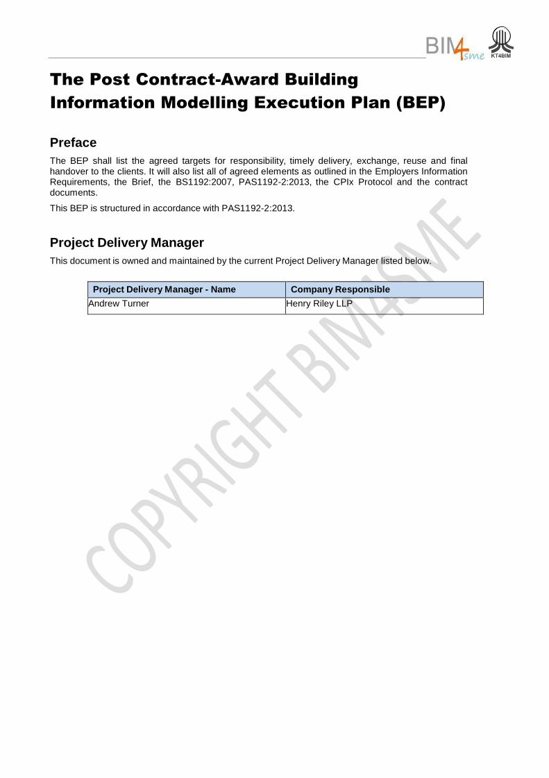
The Post Contract-Award Building
Information Modelling Execution Plan (BEP)
Preface
The BEP shall list the agreed targets for responsibility, timely delivery, exchange, reuse and final handover to the clients. It will also list all of agreed elements as outlined in the Employers Information Requirements, the Brief, the BS1192:2007, PAS1192-2:2013, the CPIx Protocol and the contract documents.
This BEP is structured in accordance with PAS1192-2:2013.
Project Delivery Manager
This document is owned and maintained by the current Project Delivery Manager listed below.
Project Delivery Manager - Name Company Responsible
Andrew Turner Henry Riley LLP
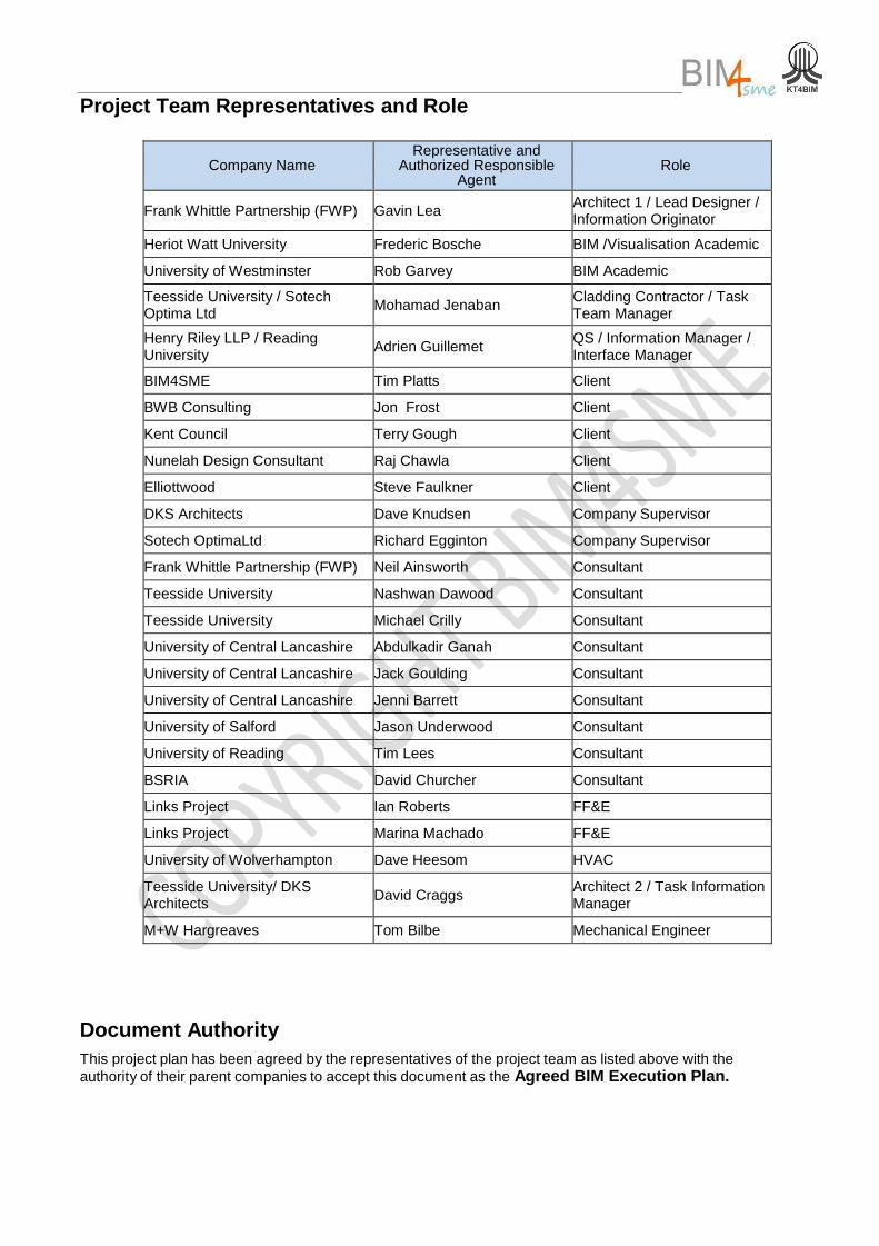
Project Team Representatives and Role
Company Name Representative and
Authorized Responsible Agent
Role
Frank Whittle Partnership (FWP) Gavin Lea Architect 1 / Lead Designer / Information Originator
Heriot Watt University Frederic Bosche BIM /Visualisation Academic
University of Westminster Rob Garvey BIM Academic
Teesside University / Sotech Optima Ltd
Mohamad Jenaban Cladding Contractor / Task Team Manager
Henry Riley LLP / Reading University
Adrien Guillemet QS / Information Manager / Interface Manager
BIM4SME Tim Platts Client
BWB Consulting Jon Frost Client
Kent Council Terry Gough Client
Nunelah Design Consultant Raj Chawla Client
Elliottwood Steve Faulkner Client
DKS Architects Dave Knudsen Company Supervisor
Sotech OptimaLtd Richard Egginton Company Supervisor
Frank Whittle Partnership (FWP) Neil Ainsworth Consultant
Teesside University Nashwan Dawood Consultant
Teesside University Michael Crilly Consultant
University of Central Lancashire Abdulkadir Ganah Consultant
University of Central Lancashire Jack Goulding Consultant
University of Central Lancashire Jenni Barrett Consultant
University of Salford Jason Underwood Consultant
University of Reading Tim Lees Consultant
BSRIA David Churcher Consultant
Links Project Ian Roberts FF&E
Links Project Marina Machado FF&E
University of Wolverhampton Dave Heesom HVAC
Teesside University/ DKS Architects
David Craggs Architect 2 / Task Information Manager
M+W Hargreaves Tom Bilbe Mechanical Engineer
Document Authority
This project plan has been agreed by the representatives of the project team as listed above with the
authority of their parent companies to accept this document as the Agreed BIM Execution Plan.
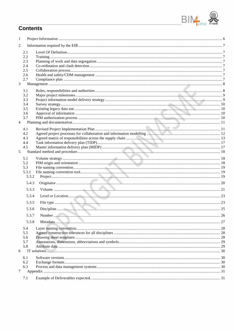
Contents
1 Project Information ..................................................................................................................................................................... 6
2 Information required by the EIR ................................................................................................................................................. 7
2.1 Level Of Definition ............................................................................................................................................................ 7 2.2 Training .............................................................................................................................................................................. 7 2.3 Planning of work and data segregation .............................................................................................................................. 7 2.4 Co-ordination and clash detection ...................................................................................................................................... 7 2.5 Collaboration process ......................................................................................................................................................... 7 2.6 Health and safety/CDM management ................................................................................................................................ 7 2.7 Compliance plan ................................................................................................................................................................ 7
3 Management ............................................................................................................................................................................... 8
3.1 Roles, responsibilities and authorities ................................................................................................................................ 8 3.2 Major project milestones .................................................................................................................................................... 9 3.3 Project information model delivery strategy ...................................................................................................................... 9 3.4 Survey strategy ................................................................................................................................................................. 10 3.5 Existing legacy data use ................................................................................................................................................... 10 3.6 Approval of information .................................................................................................................................................. 10 3.7 PIM authorization process ............................................................................................................................................... 10
4 Planning and documentation ..................................................................................................................................................... 11
4.1 Revised Project Implementation Plan .............................................................................................................................. 11 4.2 Agreed project processes for collaboration and information modelling .......................................................................... 12 4.3 Agreed matrix of responsibilities across the supply chain ............................................................................................... 13 4.4 Task information delivery plan (TIDP) ............................................................................................................................ 17 4.5 Master information delivery plan (MIDP) ....................................................................................................................... 17
5 Standard method and procedure ................................................................................................................................................ 18
5.1 Volume strategy ............................................................................................................................................................... 18 5.2 PIM origin and orientation ............................................................................................................................................... 18 5.3 File naming convention .................................................................................................................................................... 19 5.3.1 File naming convention tool............................................................................................................................................. 19
5.3.2 Project .......................................................................................................................................................................... 19
5.4.3 Originator ..................................................................................................................................................................... 20
5.3.3 Volume ........................................................................................................................................................................ 21
5.3.4 Level or Location ......................................................................................................................................................... 23
5.3.5 File type ....................................................................................................................................................................... 23
5.3.6 Discipline ..................................................................................................................................................................... 25
5.3.7 Number ........................................................................................................................................................................ 26
5.3.8 Metadata ...................................................................................................................................................................... 27
5.4 Layer naming convention ................................................................................................................................................. 28 5.5 Agreed construction tolerances for all disciplines ........................................................................................................... 28 5.6 Drawing sheet templates .................................................................................................................................................. 28 5.7 Annotations, dimensions, abbreviations and symbols ...................................................................................................... 29 5.8 Attribute data ................................................................................................................................................................... 29
6 IT solutions ............................................................................................................................................................................... 30
6.1 Software versions ............................................................................................................................................................. 30 6.2 Exchange formats ............................................................................................................................................................. 30 6.3 Process and data management systems ............................................................................................................................ 30
7 Appendix .................................................................................................................................................................................. 31
7.1 Example of Deliverables expected. .................................................................................................................................. 31
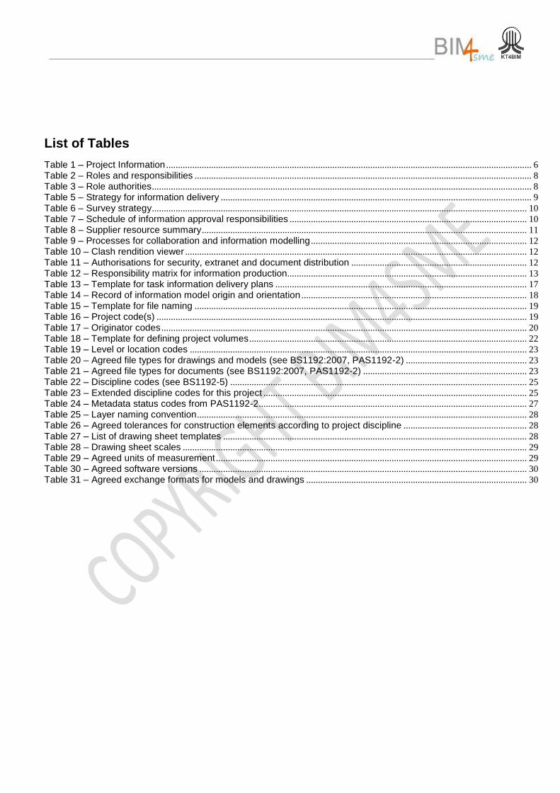
List of Tables
Table 1 – Project Information .......................................................................................................................................................... 6 Table 2 – Roles and responsibilities .............................................................................................................................................. 8 Table 3 – Role authorities ................................................................................................................................................................ 8 Table 5 – Strategy for information delivery ................................................................................................................................... 9 Table 6 – Survey strategy .............................................................................................................................................................. 10 Table 7 – Schedule of information approval responsibilities .................................................................................................... 10 Table 8 – Supplier resource summary ......................................................................................................................................... 11 Table 9 – Processes for collaboration and information modelling ........................................................................................... 12 Table 10 – Clash rendition viewer ................................................................................................................................................ 12 Table 11 – Authorisations for security, extranet and document distribution .......................................................................... 12 Table 12 – Responsibility matrix for information production..................................................................................................... 13 Table 13 – Template for task information delivery plans .......................................................................................................... 17 Table 14 – Record of information model origin and orientation ............................................................................................... 18 Table 15 – Template for file naming ............................................................................................................................................ 19 Table 16 – Project code(s) ............................................................................................................................................................ 19 Table 17 – Originator codes .......................................................................................................................................................... 20 Table 18 – Template for defining project volumes ..................................................................................................................... 22 Table 19 – Level or location codes .............................................................................................................................................. 23 Table 20 – Agreed file types for drawings and models (see BS1192:2007, PAS1192-2) ................................................... 23 Table 21 – Agreed file types for documents (see BS1192:2007, PAS1192-2) ..................................................................... 23 Table 22 – Discipline codes (see BS1192-5) ............................................................................................................................. 25 Table 23 – Extended discipline codes for this project ............................................................................................................... 25 Table 24 – Metadata status codes from PAS1192-2 ................................................................................................................. 27 Table 25 – Layer naming convention ........................................................................................................................................... 28 Table 26 – Agreed tolerances for construction elements according to project discipline .................................................... 28 Table 27 – List of drawing sheet templates ................................................................................................................................ 28 Table 28 – Drawing sheet scales ................................................................................................................................................. 29 Table 29 – Agreed units of measurement ................................................................................................................................... 29 Table 30 – Agreed software versions .......................................................................................................................................... 30 Table 31 – Agreed exchange formats for models and drawings ............................................................................................. 30
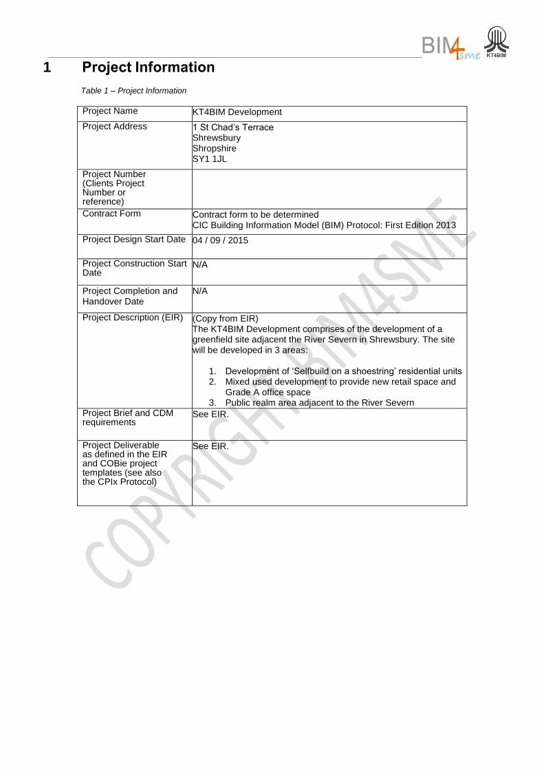
1 Project Information
Table 1 – Project Information
Project Name KT4BIM Development
Project Address 1 St Chad’s Terrace Shrewsbury Shropshire SY1 1JL
Project Number (Clients Project Number or reference)
Contract Form Contract form to be determined CIC Building Information Model (BIM) Protocol: First Edition 2013
Project Design Start Date 04 / 09 / 2015
Project Construction Start Date
N/A
Project Completion and Handover Date
N/A
Project Description (EIR) (Copy from EIR) The KT4BIM Development comprises of the development of a greenfield site adjacent the River Severn in Shrewsbury. The site will be developed in 3 areas:
1. Development of ‘Selfbuild on a shoestring’ residential units 2. Mixed used development to provide new retail space and
Grade A office space 3. Public realm area adjacent to the River Severn
May be an additional document, please reference.
Project Brief and CDM requirements
See EIR.
Project Deliverable as defined in the EIR and COBie project templates (see also the CPIx Protocol)
See EIR.
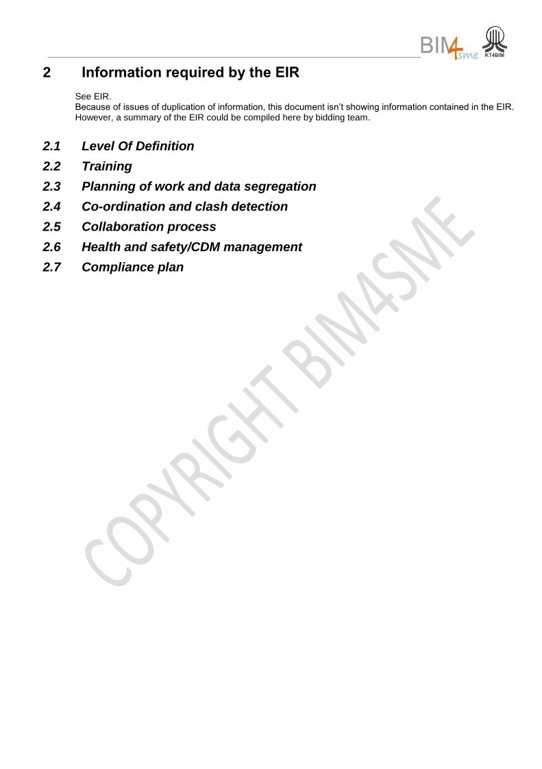
2 Information required by the EIR
See EIR. Because of issues of duplication of information, this document isn’t showing information contained in the EIR. However, a summary of the EIR could be compiled here by bidding team.
2.1 Level Of Definition
2.2 Training
2.3 Planning of work and data segregation
2.4 Co-ordination and clash detection
2.5 Collaboration process
2.6 Health and safety/CDM management
2.7 Compliance plan
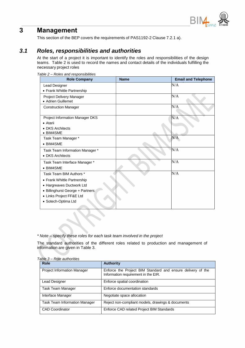
3 Management This section of the BEP covers the requirements of PAS1192-2 Clause 7.2.1 a).
3.1 Roles, responsibilities and authorities At the start of a project it is important to identify the roles and responsibilities of the design teams. Table 2 is used to record the names and contact details of the individuals fulfilling the necessary project roles
Table 2 – Roles and responsibilities
* Note – specify these roles for each task team involved in the project
The standard authorities of the different roles related to production and management of information are given in Table 3.
Table 3 – Role authorities
Role Authority
Project Information Manager Enforce the Project BIM Standard and ensure delivery of the Information requirement in the EIR.
Lead Designer Enforce spatial coordination
Task Team Manager Enforce documentation standards
Interface Manager Negotiate space allocation
Task Team Information Manager Reject non-compliant models, drawings & documents
CAD Coordinator Enforce CAD related Project BIM Standards
Role Company Name Email and Telephone number
Lead Designer
Frank Whittle Partnership
N/A
Project Delivery Manager
Adrien Guillemet
N/A
Construction Manager
N/A
Project Information Manager DKS
Atarii
DKS Architects
BIM4SME
N/A
Task Team Manager *
BIM4SME
N/A
Task Team Information Manager *
DKS Architects
N/A
Task Team Interface Manager *
BIM4SME
N/A
Task Team BIM Authors *
Frank Whittle Partnership
Hargreaves Ductwork Ltd
Billinghurst George + Partners
Links Project FF&E Ltd
Sotech-Optima Ltd
N/A
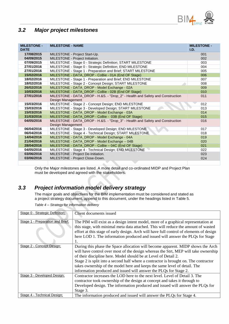
3.2 Major project milestones
MILESTONE - DATE
MILESTONE - NAME MILESTONE - I.D.
17/08/2015 MILESTONE - Project Start-Up. 001 04/09/2015 MILESTONE - Project Initiation. 002 07/09/2015 MILESTONE - Stage 0 - Strategic Definition; START MILESTONE 003 27/01/2016 MILESTONE - Stage 0 - Strategic Definition; END MILESTONE 004 27/01/2016 MILESTONE - Stage 1 - Preparation and Brief; START MILESTONE 005 15/02/2016 MILESTONE - DATA_DROP - CoBie - 01A (End OF Stage) 006 18/02/2016 MILESTONE - Stage 1 - Preparation and Brief; END MILESTONE 007 18/02/2016 MILESTONE - Stage 2 - Concept Design; START MILESTONE 008 26/02/2016 MILESTONE - DATA_DROP - Model Exchange - 02A 009 10/03/2016 MILESTONE - DATA_DROP - CoBie - 02B (End OF Stage) 010 27/01/2016 MILESTONE - DATA_DROP - H.&S. - "Drop_2" - Health and Safety and Construction
Design Management 011
15/03/2016 MILESTONE - Stage 2 - Concept Design; END MILESTONE 012 15/03/2016 MILESTONE - Stage 3 - Developed Design; START MILESTONE 013 15/03/2016 MILESTONE - DATA_DROP - Model Exchange - 03A 014 31/03/2016 MILESTONE - DATA_DROP - CoBie - 03B (End OF Stage) 015 04/05/2016 MILESTONE - DATA_DROP - H.&S. - "Drop_3" - Health and Safety and Construction
Design Management 016
06/04/2016 MILESTONE - Stage 3 - Developed Design; END MILESTONE 017 06/04/2016 MILESTONE - Stage 4 - Technical Design; START MILESTONE 018 14/04/2016 MILESTONE - DATA_DROP - Model Exchange - 04A 019 21/04/2016 MILESTONE - DATA_DROP - Model Exchange – 04B 020
28/04/2016 MILESTONE - DATA_DROP - CoBie – 04C (End OF Stage) 021 04/05/2016 MILESTONE - Stage 4 - Technical Design; END MILESTONE 022 03/06/2016 MILESTONE - Project De-Initiation. 023 03/06/2016 MILESTONE - Project Close-Down. 024
Only the Major milestones are listed. A more detail and co-ordinated MIDP and Project Plan must be developed and agreed with the stakeholders.
3.3 Project information model delivery strategy The major goals and objectives for the BIM implementation must be considered and stated as a project strategy document, append to this document, under the headings listed in Table 5.
Table 4 – Strategy for information delivery
Stage 0 - Strategic Definition;
Client documents issued
Stage 1 - Preparation and Brief; The PIM will exist as a design intent model, more of a graphical representation at
this stage, with minimal meta data attached. This will reduce the amount of wasted
effort at this stage of early design. Arch will have full control of elements of design
here LOD 1. The information produced and issued will answer the PLQs for Stage
1. Stage 2 - Concept Design; During this phase the Space allocation will become apparent. MIDP shows the Arch
will have control over most of the design whereas the Strt, MEP will take ownership
of their discipline here. Model should be at Level of Detail 2.
Stage 2 is split into a second half where a contractor is brought on. The contractor
takes ownership of the model here and keeps the same level of detail. The
information produced and issued will answer the PLQs for Stage 2. Stage 3 - Developed Design;
Contractor increases the LOD here to the next level. Level of Detail 3. The
contractor took ownership of the design at concept and takes it through to
Developed design. The information produced and issued will answer the PLQs for
Stage 3. Stage 4 - Technical Design; The information produced and issued will answer the PLQs for Stage 4.
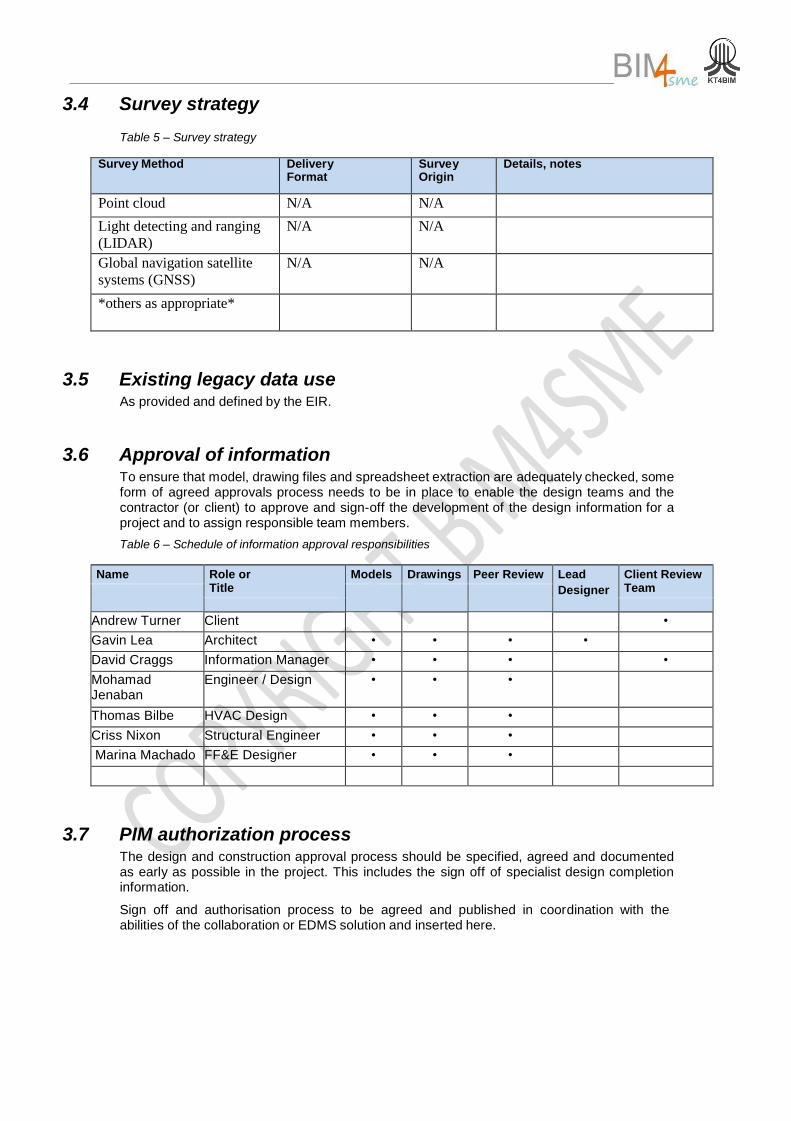
3.4 Survey strategy
Table 5 – Survey strategy
Survey Method Delivery Format
Survey Origin
Details, notes
Point cloud N/A N/A
Light detecting and ranging
(LIDAR)
N/A N/A
Global navigation satellite
systems (GNSS)
N/A N/A
*others as appropriate*
3.5 Existing legacy data use As provided and defined by the EIR.
3.6 Approval of information To ensure that model, drawing files and spreadsheet extraction are adequately checked, some form of agreed approvals process needs to be in place to enable the design teams and the contractor (or client) to approve and sign-off the development of the design information for a project and to assign responsible team members.
Table 6 – Schedule of information approval responsibilities
Name Role or Title
Models Drawings Peer Review Lead
Designer
Client Review Team
Andrew Turner Client •
Gavin Lea Architect • • • •
David Craggs Information Manager • • • •
Mohamad Jenaban
Engineer / Design • • •
Thomas Bilbe HVAC Design • • •
Criss Nixon Structural Engineer • • •
Marina Machado FF&E Designer • • •
3.7 PIM authorization process The design and construction approval process should be specified, agreed and documented as early as possible in the project. This includes the sign off of specialist design completion information.
Sign off and authorisation process to be agreed and published in coordination with the abilities of the collaboration or EDMS solution and inserted here.
4 Planning and documentation This section of the BEP covers the requirements of PAS1192-2 Clause 7.2.1 b).
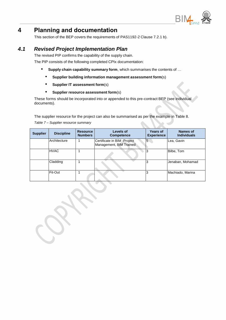
4.1 Revised Project Implementation Plan The revised PIP confirms the capability of the supply chain.
The PIP consists of the following completed CPIx documentation:
Supply chain capability summary form, which summarises the contents of …
Supplier building information management assessment form(s)
Supplier IT assessment form(s)
Supplier resource assessment form(s)
These forms should be incorporated into or appended to this pre-contract BEP (see individual documents).
The supplier resource for the project can also be summarised as per the example in Table 8.
Table 7 – Supplier resource summary
Supplier Discipline Resource Numbers
Levels of Competence
Years of Experience
Names of Individuals
Architecture 1 Certificate in BIM -Project Management, BIM Trained
5 Lea, Gavin
HVAC 1 3 Bilbe, Tom
Cladding 1 3 Jenaban, Mohamad
Fit-Out 1 3 Machiado, Marina
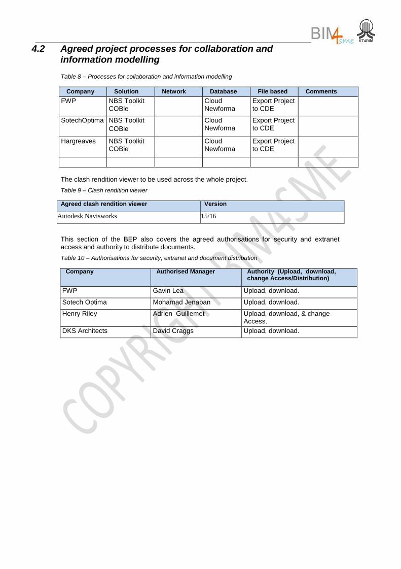
4.2 Agreed project processes for collaboration and information modelling
Table 8 – Processes for collaboration and information modelling
Company Solution Network Database File based Comments
FWP NBS Toolkit COBie
Cloud Newforma
Export Project to CDE
SotechOptima NBS Toolkit
COBie
Cloud Newforma
Export Project to CDE
Hargreaves NBS Toolkit COBie
Cloud Newforma
Export Project to CDE
The clash rendition viewer to be used across the whole project.
Table 9 – Clash rendition viewer
Agreed clash rendition viewer Version
Autodesk Navisworks 15/16
This section of the BEP also covers the agreed authorisations for security and extranet access and authority to distribute documents.
Table 10 – Authorisations for security, extranet and document distribution
Company Authorised Manager Authority (Upload, download, change Access/Distribution)
FWP Gavin Lea Upload, download.
Sotech Optima Mohamad Jenaban Upload, download.
Henry Riley Adrien Guillemet Upload, download, & change Access.
DKS Architects David Craggs Upload, download.
13
Post Contract BIM Execution Plan © (BIM4MSE)
21/01//2016
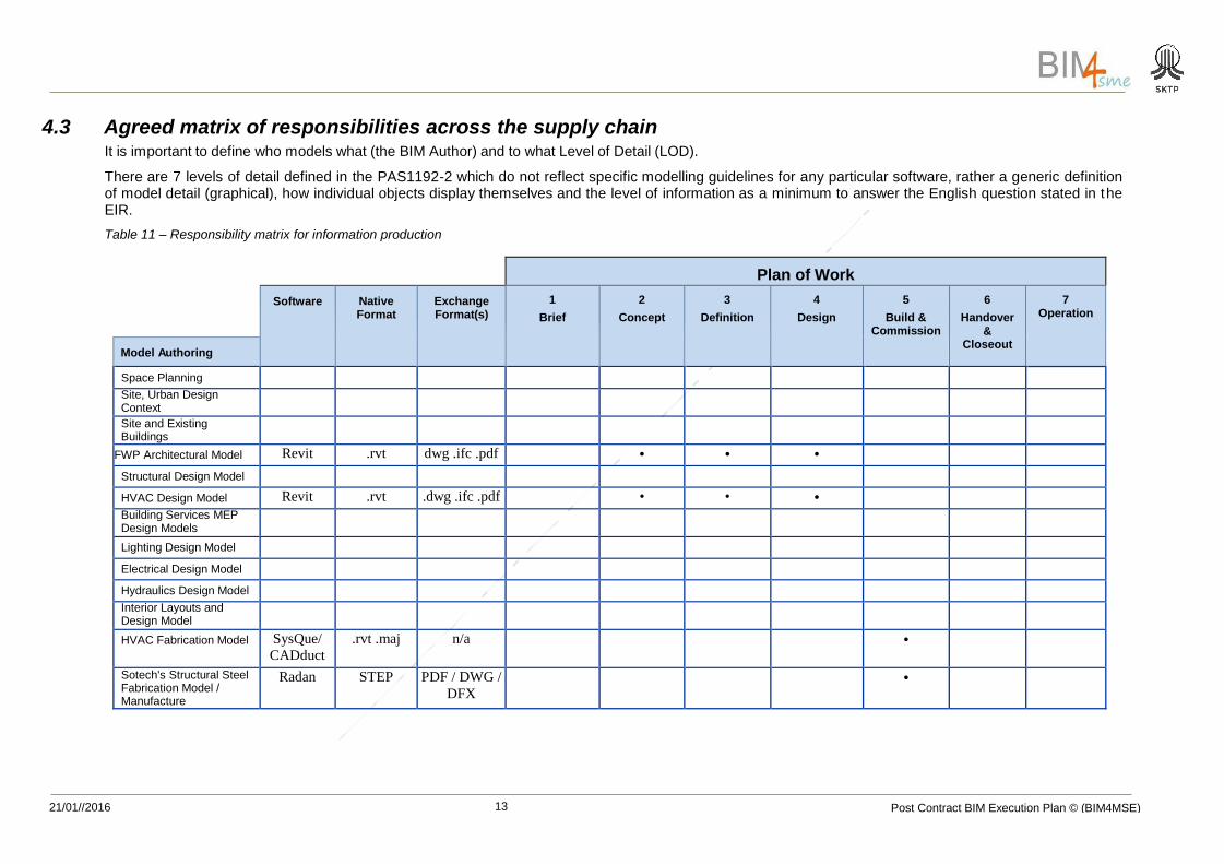
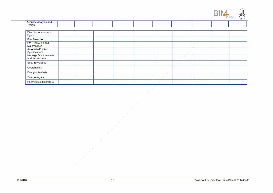
4.3 Agreed matrix of responsibilities across the supply chain It is important to define who models what (the BIM Author) and to what Level of Detail (LOD).
There are 7 levels of detail defined in the PAS1192-2 which do not reflect specific modelling guidelines for any particular software, rather a generic definition of model detail (graphical), how individual objects display themselves and the level of information as a minimum to answer the English question stated in t he EIR.
Table 11 – Responsibility matrix for information production
Plan of Work
Software
Native Format
Exchange Format(s)
1
Brief
2
Concept
3
Definition
4
Design
5
Build & Commission
6
Handover &
Closeout
7 Operation
Model Authoring
Space Planning
Site, Urban Design Context
Site and Existing Buildings
FWP Architectural Model Revit .rvt dwg .ifc .pdf • • •
Structural Design Model
HVAC Design Model Revit .rvt .dwg .ifc .pdf • • •
Building Services MEP Design Models
Lighting Design Model
Electrical Design Model
Hydraulics Design Model
Interior Layouts and Design Model
HVAC Fabrication Model SysQue/
CADduct
.rvt .maj n/a •
Sotech's Structural Steel Fabrication Model / Manufacture
Radan STEP PDF / DWG /
DFX
•
14
Post Contract BIM Execution Plan © (BIM4SME)
1/5/2016
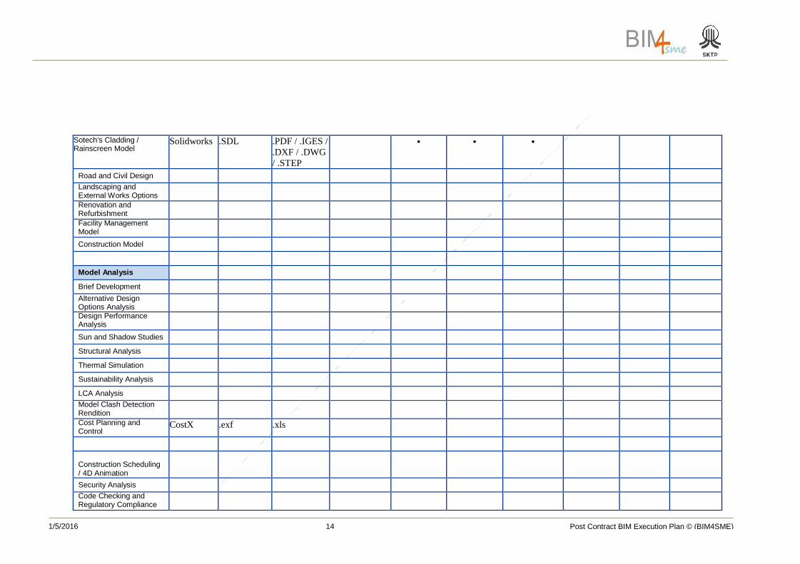
Sotech's Cladding / Rainscreen Model
Solidworks .SDL .PDF / .IGES /
.DXF / .DWG
/ .STEP
• • •
Road and Civil Design
Landscaping and External Works Options
Renovation and Refurbishment
Facility Management Model
Construction Model
Model Analysis
Brief Development
Alternative Design Options Analysis
Design Performance Analysis
Sun and Shadow Studies
Structural Analysis
Thermal Simulation
Sustainability Analysis
LCA Analysis
Model Clash Detection Rendition
Cost Planning and Control
CostX .exf .xls
Construction Scheduling / 4D Animation
Security Analysis
Code Checking and Regulatory Compliance
15
Post Contract BIM Execution Plan © (BIM4SME)
1/5/2016
Acoustic Analysis and Design
Disabled Access and Egress
Fire Protection
FM, Operation and Maintenance
Automated/Linked Specifications
Heritage Documentation and Assessment
Solar Envelopes
Overshading
Daylight Analysis
Solar Analysis
Photovoltaic Collectors
21/01//2016 Post Contract BIM Execution Plan © (BIM3SME)
17
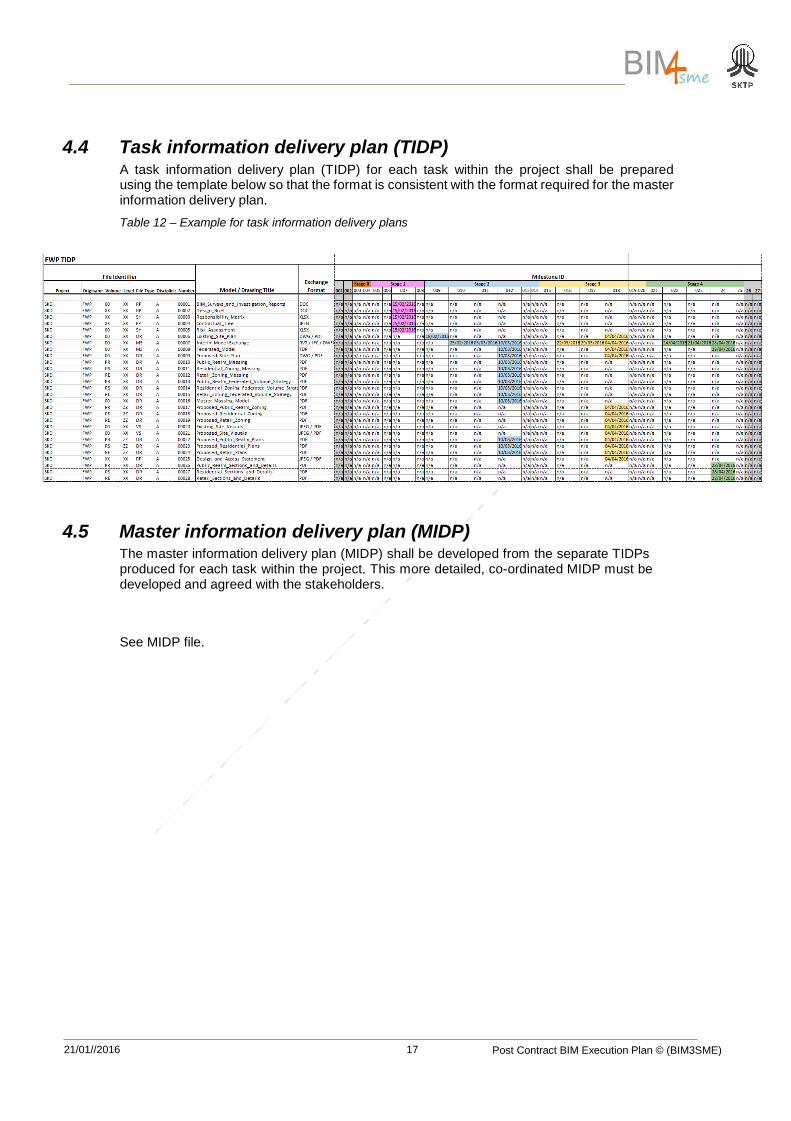
4.4 Task information delivery plan (TIDP) A task information delivery plan (TIDP) for each task within the project shall be prepared using the template below so that the format is consistent with the format required for the master information delivery plan.
Table 12 – Example for task information delivery plans
4.5 Master information delivery plan (MIDP) The master information delivery plan (MIDP) shall be developed from the separate TIDPs produced for each task within the project. This more detailed, co-ordinated MIDP must be developed and agreed with the stakeholders.
See MIDP file.
21/01//2016 Post Contract BIM Execution Plan © (BIM3SME)
18
5 Standard method and procedure This section of the BEP covers the requirements of PAS1192-2 Clause 7.2.1 c).
5.1 Volume strategy See Section 5.3 (file naming convention), sub-section Volume for the definitions and abbreviations of volumes to be used on the project.
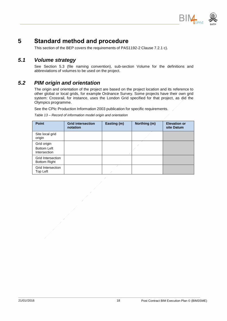
5.2 PIM origin and orientation The origin and orientation of the project are based on the project location and its reference to other global or local grids, for example Ordnance Survey. Some projects have their own grid system: Crossrail, for instance, uses the London Grid specified for that project, as did the Olympics programme.
See the CPIc Production Information 2003 publication for specific requirements.
Table 13 – Record of information model origin and orientation
Point Grid intersection notation
Easting (m) Northing (m) Elevation or site Datum
Site local grid origin
Grid origin
Bottom Left Intersection
Grid Intersection Bottom Right
Grid Intersection Top Left
21/01//2016 Post Contract BIM Execution Plan © (BIM3SME)
19
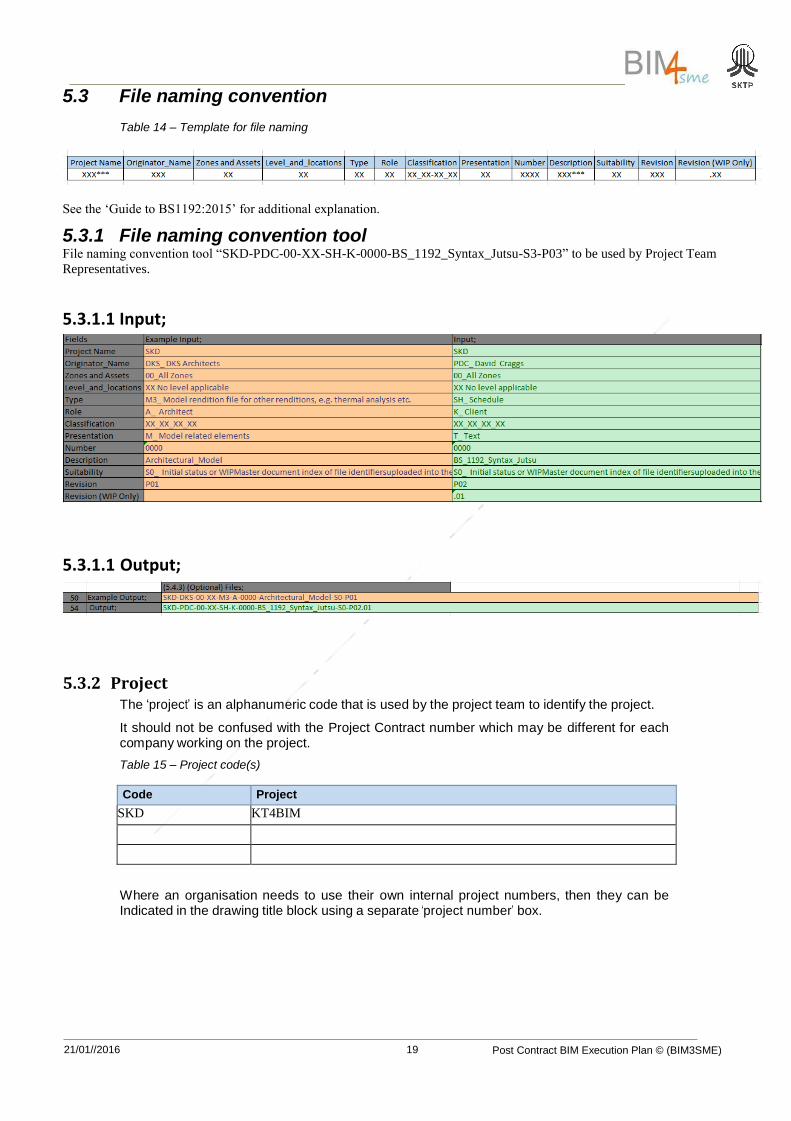
5.3 File naming convention Table 14 – Template for file naming
See the ‘Guide to BS1192:2015’ for additional explanation.
5.3.1 File naming convention tool File naming convention tool “SKD-PDC-00-XX-SH-K-0000-BS_1192_Syntax_Jutsu-S3-P03” to be used by Project Team
Representatives.
5.3.1.1 Input;
5.3.1.1 Output;
5.3.2 Project The ‘project’ is an alphanumeric code that is used by the project team to identify the project.
It should not be confused with the Project Contract number which may be different for each company working on the project.
Table 15 – Project code(s)
Code Project
SKD KT4BIM
Where an organisation needs to use their own internal project numbers, then they can be Indicated in the drawing title block using a separate ‘project number’ box.
21/01//2016 Post Contract BIM Execution Plan © (BIM3SME)
20
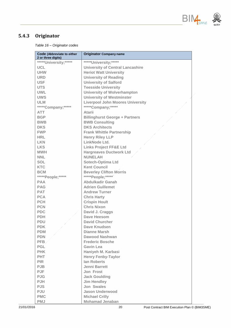
5.4.3 Originator
Table 16 – Originator codes
Code (Abbreviate to either 2 or three digits)
Originator Company name
*****University;*****
UCL
UHW
URD
USF
UTS
UWL
UWS
ULM
*****Company;*****
ATT
BGP
BWB
DKS
FWP
HRL
LKN
LKS
MWH
NNL
SOL
KTC
BCM
*****People;*****
PAA
PAG
PAT
PCA
PCH
PCN
PDC
PDH
PDU
PDK
PDM
PDN
PFB
PGL
PHK
PHT
PIR
PJB
PJF
PJG
PJH
PJS
PJU
PMC
PMJ
*****University;*****
University of Central Lancashire
Heriot Watt University
University of Reading
University of Salford
Teesside University
University of Wolverhampton
University of Westminster
Liverpool John Moores University
*****Company;*****
Atarii
Billinghurst George + Partners
BWB Consulting
DKS Architects
Frank Whittle Partnership
Henry Riley LLP
LinkNode Ltd.
Links Project FF&E Ltd
Hargreaves Ductwork Ltd
NUNELAH
Sotech-Optima Ltd
Kent Council
Beverley Clifton Morris
*****People;*****
Abdulkadir Ganah
Adrien Guillemet
Andrew Turner
Chris Harty
Crispin Hoult
Chris Nixon
David J. Craggs
Dave Heesom
David Churcher
Dave Knudsen
Dianne Marsh
Dawood Nashwan
Frederic Bosche
Gavin Lea
Haniyeh M. Karbasi
Henry Fenby-Taylor
Ian Roberts
Jenni Barrett
Jon Frost
Jack Goulding
Jim Hendley
Jon Swales
Jason Underwood
Michael Crilly
Mohamad Jenaban
21/01//2016 Post Contract BIM Execution Plan © (BIM3SME)
21
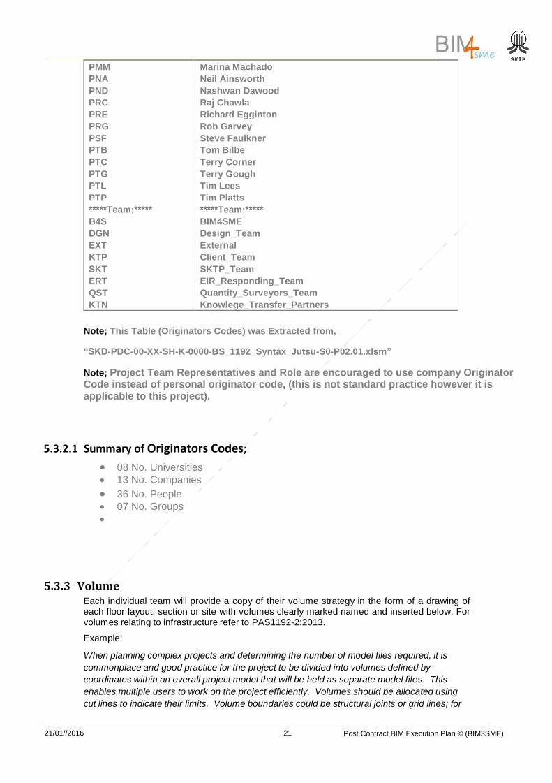
PMM
PNA
PND
PRC
PRE
PRG
PSF
PTB
PTC
PTG
PTL
PTP
*****Team;*****
B4S
DGN
EXT
KTP
SKT
ERT
QST
KTN
Marina Machado
Neil Ainsworth
Nashwan Dawood
Raj Chawla
Richard Egginton
Rob Garvey
Steve Faulkner
Tom Bilbe
Terry Corner
Terry Gough
Tim Lees
Tim Platts
*****Team;*****
BIM4SME
Design_Team
External
Client_Team
SKTP_Team
EIR_Responding_Team
Quantity_Surveyors_Team
Knowlege_Transfer_Partners
Note; This Table (Originators Codes) was Extracted from,
“SKD-PDC-00-XX-SH-K-0000-BS_1192_Syntax_Jutsu-S0-P02.01.xlsm”
Note; Project Team Representatives and Role are encouraged to use company Originator Code instead of personal originator code, (this is not standard practice however it is applicable to this project).
5.3.2.1 Summary of Originators Codes;
08 No. Universities 13 No. Companies
36 No. People 07 No. Groups
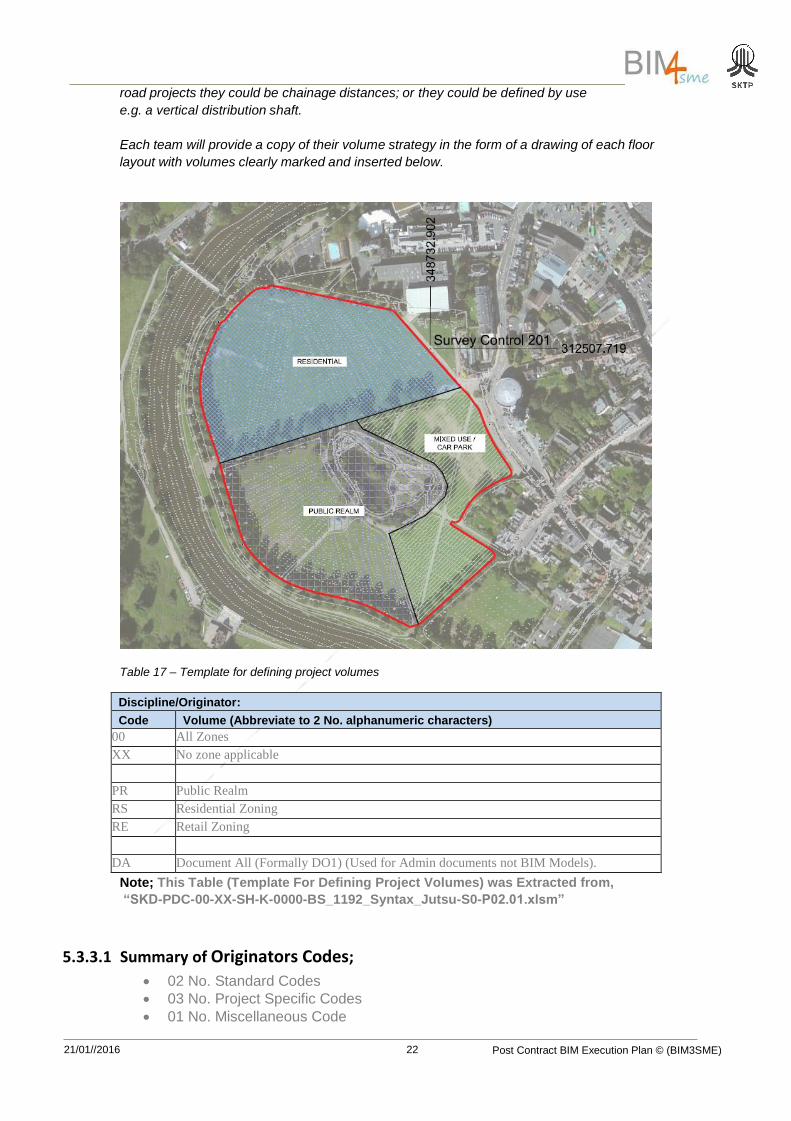
5.3.3 Volume Each individual team will provide a copy of their volume strategy in the form of a drawing of each floor layout, section or site with volumes clearly marked named and inserted below. For volumes relating to infrastructure refer to PAS1192-2:2013.
Example:
When planning complex projects and determining the number of model files required, it is
commonplace and good practice for the project to be divided into volumes defined by
coordinates within an overall project model that will be held as separate model files. This
enables multiple users to work on the project efficiently. Volumes should be allocated using
cut lines to indicate their limits. Volume boundaries could be structural joints or grid lines; for
21/01//2016 Post Contract BIM Execution Plan © (BIM3SME)
22
road projects they could be chainage distances; or they could be defined by use
e.g. a vertical distribution shaft.
Each team will provide a copy of their volume strategy in the form of a drawing of each floor
layout with volumes clearly marked and inserted below.
Table 17 – Template for defining project volumes
Discipline/Originator:
Code Volume (Abbreviate to 2 No. alphanumeric characters)
00 All Zones
XX No zone applicable
PR Public Realm
RS
Residential Zoning
RE Retail Zoning
DA Document All (Formally DO1) (Used for Admin documents not BIM Models).
Note; This Table (Template For Defining Project Volumes) was Extracted from,
“SKD-PDC-00-XX-SH-K-0000-BS_1192_Syntax_Jutsu-S0-P02.01.xlsm”
5.3.3.1 Summary of Originators Codes;
02 No. Standard Codes
03 No. Project Specific Codes
01 No. Miscellaneous Code
21/01//2016 Post Contract BIM Execution Plan © (BIM3SME)
23
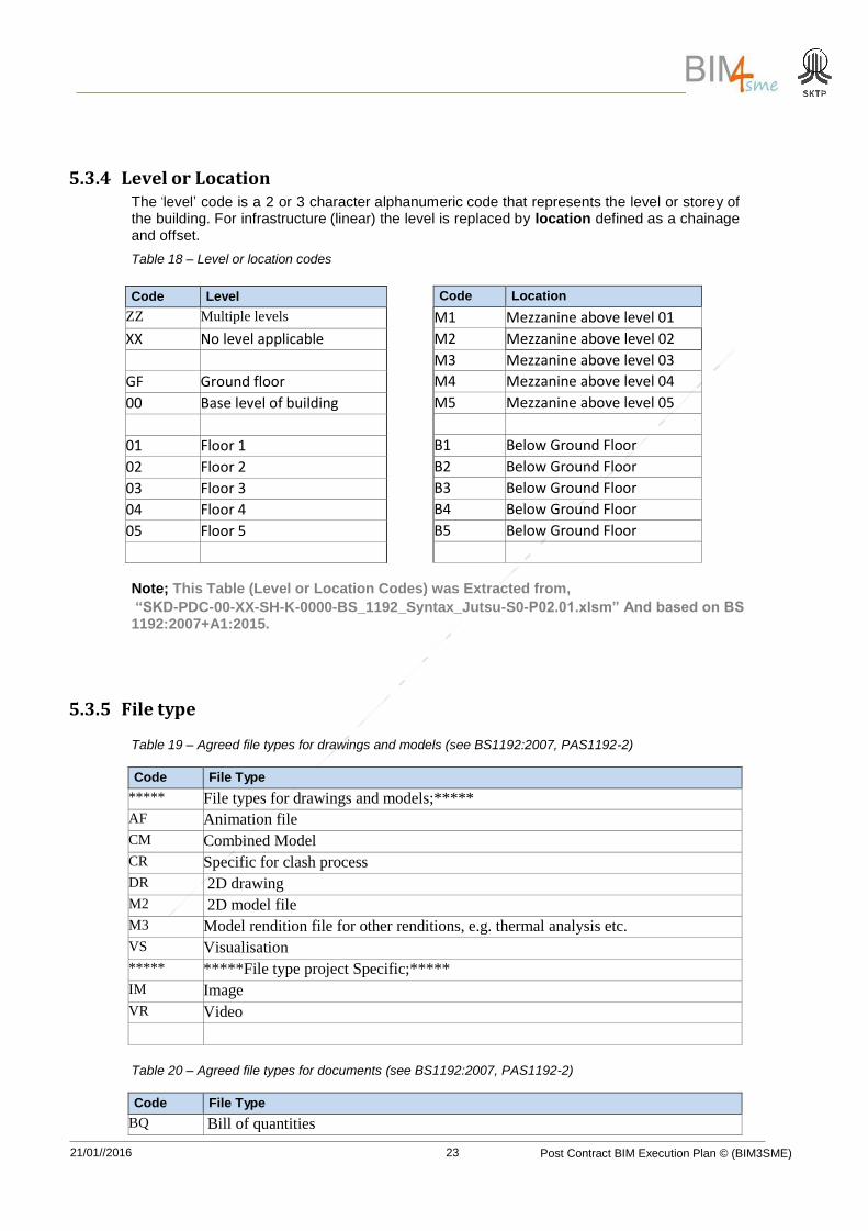
Code Location
M1 Mezzanine above level 01 M2 Mezzanine above level 02 M3 Mezzanine above level 03 M4 Mezzanine above level 04 M5 Mezzanine above level 05
B1 Below Ground Floor B2 Below Ground Floor B3 Below Ground Floor B4 Below Ground Floor B5 Below Ground Floor
5.3.4 Level or Location The ‘level’ code is a 2 or 3 character alphanumeric code that represents the level or storey of the building. For infrastructure (linear) the level is replaced by location defined as a chainage and offset.
Table 18 – Level or location codes
Note; This Table (Level or Location Codes) was Extracted from,
“SKD-PDC-00-XX-SH-K-0000-BS_1192_Syntax_Jutsu-S0-P02.01.xlsm” And based on BS 1192:2007+A1:2015.
5.3.5 File type
Table 19 – Agreed file types for drawings and models (see BS1192:2007, PAS1192-2)
Code File Type
***** File types for drawings and models;*****
AF Animation file
CM Combined Model
CR Specific for clash process
DR 2D drawing
M2 2D model file
M3 Model rendition file for other renditions, e.g. thermal analysis etc.
VS Visualisation
***** *****File type project Specific;*****
IM Image
VR Video
Table 20 – Agreed file types for documents (see BS1192:2007, PAS1192-2)
Code File Type
BQ Bill of quantities
Code Level
ZZ Multiple levels
XX No level applicable
GF Ground floor 00 Base level of building (where ground floor is not appropriate)
01 Floor 1 02 Floor 2 03 Floor 3 04 Floor 4 05 Floor 5
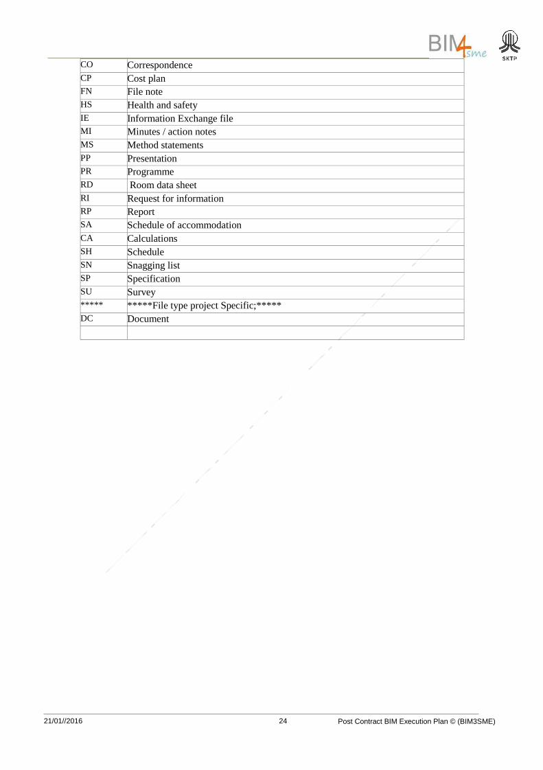
21/01//2016 Post Contract BIM Execution Plan © (BIM3SME)
24
CO Correspondence
CP Cost plan
FN File note
HS Health and safety
IE Information Exchange file
MI Minutes / action notes
MS Method statements
PP Presentation
PR Programme
RD Room data sheet
RI Request for information
RP Report
SA Schedule of accommodation
CA Calculations
SH Schedule
SN Snagging list
SP Specification
SU Survey
***** *****File type project Specific;*****
DC Document
21/01//2016 Post Contract BIM Execution Plan © (BIM3SME)
25
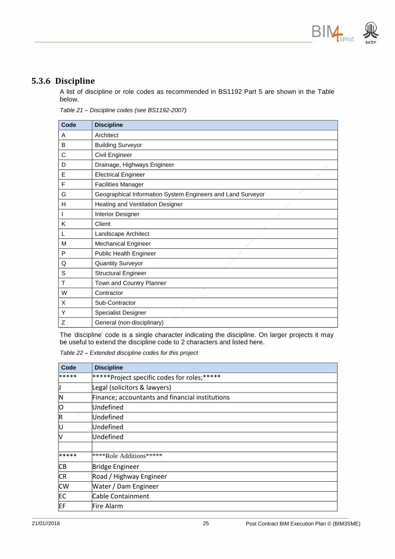
5.3.6 Discipline A list of discipline or role codes as recommended in BS1192 Part 5 are shown in the Table below.
Table 21 – Discipline codes (see BS1192-2007)
Code Discipline
A Architect
B Building Surveyor
C Civil Engineer
D Drainage, Highways Engineer
E Electrical Engineer
F Facilities Manager
G Geographical Information System Engineers and Land Surveyor
H Heating and Ventilation Designer
I Interior Designer
K Client
L Landscape Architect
M Mechanical Engineer
P Public Health Engineer
Q Quantity Surveyor
S Structural Engineer
T Town and Country Planner
W Contractor
X Sub-Contractor
Y Specialist Designer
Z General (non-disciplinary)
The ‘discipline’ code is a single character indicating the discipline. On larger projects it may be useful to extend the discipline code to 2 characters and listed here.
Table 22 – Extended discipline codes for this project
Code Discipline
***** *****Project specific codes for roles;***** J Legal (solicitors & lawyers) N_ Finance; accountants and financial institutions
N Finance; accountants and financial institutions O Undefined R Undefined U Undefined V Undefined
***** ****Role Additions*****
CB Bridge Engineer CR Road / Highway Engineer CW Water / Dam Engineer EC Cable Containment EF Fire Alarm
21/01//2016 Post Contract BIM Execution Plan © (BIM3SME)
26
EL Lighting EP Protection ES Security GA Aerial surveyors ME Combined Services MW Chilled Water MH Heating MV Ventilation PD Drainage PF Fire Services PH Public Health Services PS Sanitation and Rainwater EW Water Services RS Railways signaling RT Railways track SF Façade engineers SR Reinforcement detailers
Note; This Table (Extended Discipline Codes For This Project) was Extracted from,
“SKD-PDC-00-XX-SH-K-0000-BS_1192_Syntax_Jutsu-S0-P02.01.xlsm” And based on aecukbimprotocol-v2-0
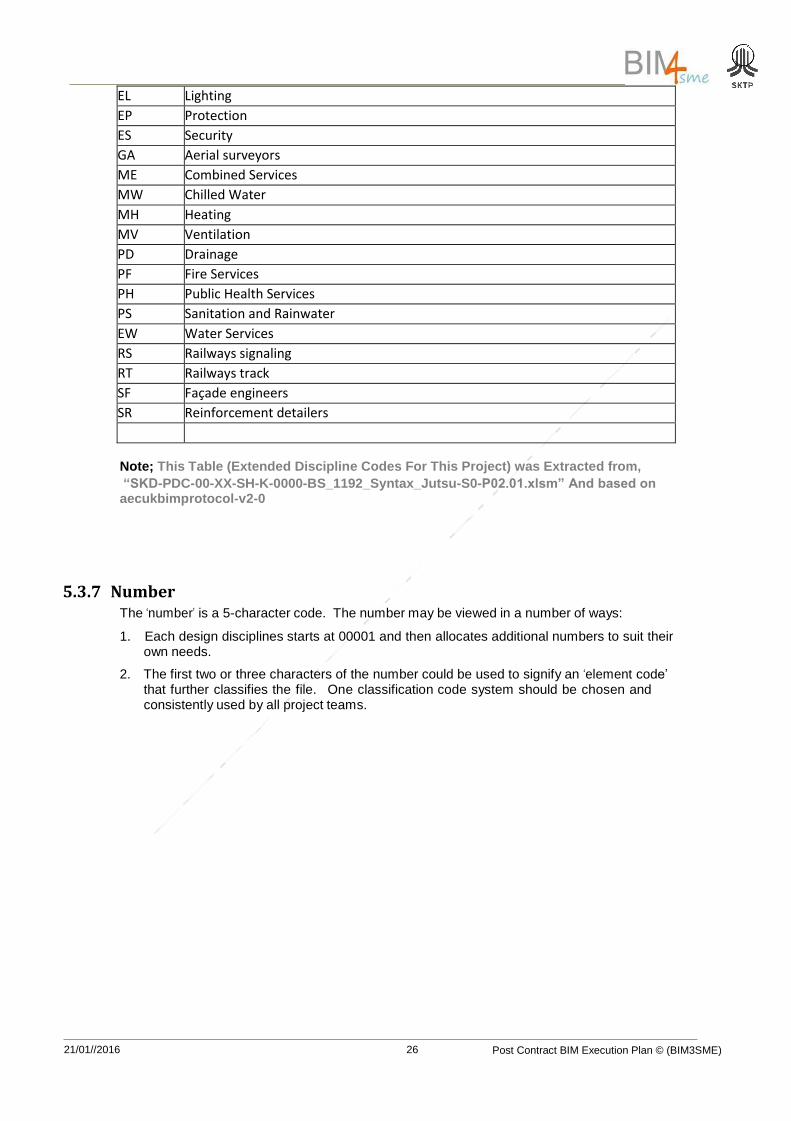
5.3.7 Number The ‘number’ is a 5-character code. The number may be viewed in a number of ways:
1. Each design disciplines starts at 00001 and then allocates additional numbers to suit their own needs.
2. The first two or three characters of the number could be used to signify an ‘element code’ that further classifies the file. One classification code system should be chosen and consistently used by all project teams.
21/01//2016 Post Contract BIM Execution Plan © (BIM3SME)
27
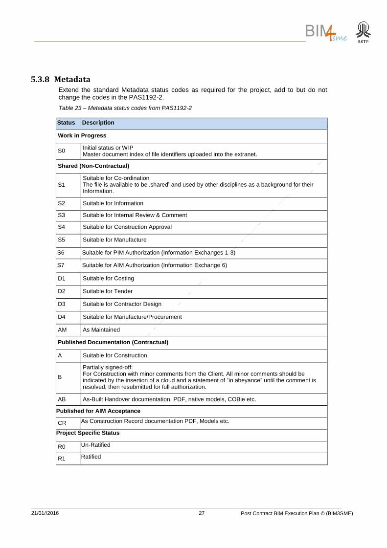
5.3.8 Metadata Extend the standard Metadata status codes as required for the project, add to but do not change the codes in the PAS1192-2.
Table 23 – Metadata status codes from PAS1192-2
Status Description
Work in Progress
S0 Initial status or WIP Master document index of file identifiers uploaded into the extranet.
Shared (Non-Contractual)
S1
Suitable for Co-ordination The file is available to be „shared‟ and used by other disciplines as a background for their Information.
S2 Suitable for Information
S3 Suitable for Internal Review & Comment
S4 Suitable for Construction Approval
S5 Suitable for Manufacture
S6 Suitable for PIM Authorization (Information Exchanges 1-3)
S7 Suitable for AIM Authorization (Information Exchange 6)
D1 Suitable for Costing
D2 Suitable for Tender
D3 Suitable for Contractor Design
D4 Suitable for Manufacture/Procurement
AM As Maintained
Published Documentation (Contractual)
A Suitable for Construction
B
Partially signed-off: For Construction with minor comments from the Client. All minor comments should be indicated by the insertion of a cloud and a statement of “in abeyance” until the comment is resolved, then resubmitted for full authorization.
AB As-Built Handover documentation, PDF, native models, COBie etc.
Published for AIM Acceptance
CR As Construction Record documentation PDF, Models etc.
Project Specific Status
R0 Un-Ratified
R1 Ratified
21/01//2016 Post Contract BIM Execution Plan © (BIM3SME)
28
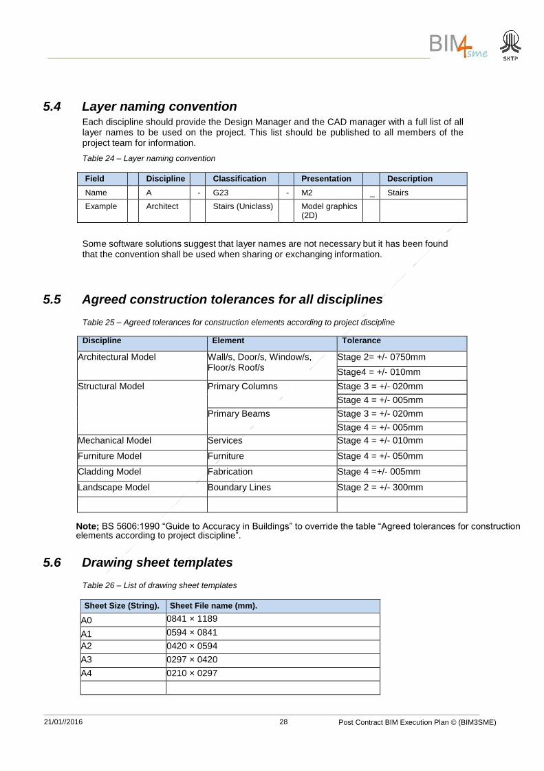
5.4 Layer naming convention Each discipline should provide the Design Manager and the CAD manager with a full list of all layer names to be used on the project. This list should be published to all members of the project team for information.
Table 24 – Layer naming convention
Field Discipline Classification Presentation Description
Name A - G23 - M2 _ Stairs
Example Architect Stairs (Uniclass) Model graphics (2D)
Some software solutions suggest that layer names are not necessary but it has been found that the convention shall be used when sharing or exchanging information.
5.5 Agreed construction tolerances for all disciplines
Table 25 – Agreed tolerances for construction elements according to project discipline
Discipline Element Tolerance
Architectural Model Wall/s, Door/s, Window/s, Floor/s Roof/s
Stage 2= +/- 0750mm
Stage4 = +/- 010mm
Structural Model Primary Columns Stage 3 = +/- 020mm
Stage 4 = +/- 005mm
Primary Beams Stage 3 = +/- 020mm
Stage 4 = +/- 005mm
Mechanical Model Services Stage 4 = +/- 010mm
Furniture Model Furniture Stage 4 = +/- 050mm
Cladding Model Fabrication Stage 4 =+/- 005mm
Landscape Model Boundary Lines Stage 2 = +/- 300mm
Note; BS 5606:1990 “Guide to Accuracy in Buildings” to override the table “Agreed tolerances for construction elements according to project discipline”.
5.6 Drawing sheet templates
Table 26 – List of drawing sheet templates
Sheet Size (String). Sheet File name (mm).
A0 0841 × 1189
A1 0594 × 0841
A2 0420 × 0594
A3 0297 × 0420
A4 0210 × 0297
21/01//2016 Post Contract BIM Execution Plan © (BIM3SME)
29
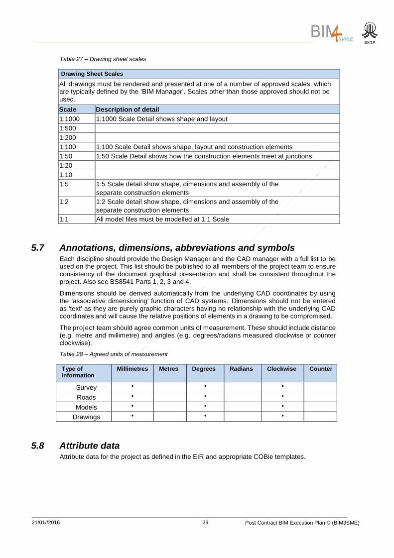
Table 27 – Drawing sheet scales
Drawing Sheet Scales
All drawings must be rendered and presented at one of a number of approved scales, which are typically defined by the ‘BIM Manager’. Scales other than those approved should not be used.
Scale Description of detail
1:1000 1:1000 Scale Detail shows shape and layout
1:500
1:200
1:100 1:100 Scale Detail shows shape, layout and construction elements
1:50 1:50 Scale Detail shows how the construction elements meet at junctions
1:20
1:10
1:5 1:5 Scale detail show shape, dimensions and assembly of the
separate construction elements
1:2 1:2 Scale detail show shape, dimensions and assembly of the
separate construction elements
1:1 All model files must be modelled at 1:1 Scale
5.7 Annotations, dimensions, abbreviations and symbols Each discipline should provide the Design Manager and the CAD manager with a full list to be used on the project. This list should be published to all members of the project team to ensure consistency of the document graphical presentation and shall be consistent throughout the project. Also see BS8541 Parts 1, 2, 3 and 4.
Dimensions should be derived automatically from the underlying CAD coordinates by using the 'associative dimensioning' function of CAD systems. Dimensions should not be entered as 'text' as they are purely graphic characters having no relationship with the underlying CAD coordinates and will cause the relative positions of elements in a drawing to be compromised.
The project team should agree common units of measurement. These should include distance (e.g. metre and millimetre) and angles (e.g. degrees/radians measured clockwise or counter clockwise).
Table 28 – Agreed units of measurement
Type of information
Millimetres Metres Degrees Radians Clockwise Counter
Survey • • •
Roads • • •
Models • • •
Drawings • • •
5.8 Attribute data Attribute data for the project as defined in the EIR and appropriate COBie templates.
21/01//2016 Post Contract BIM Execution Plan © (BIM3SME)
30
6 IT solutions This section of the BEP covers the requirements of PAS1192-2 Clause 7.2.1 d).
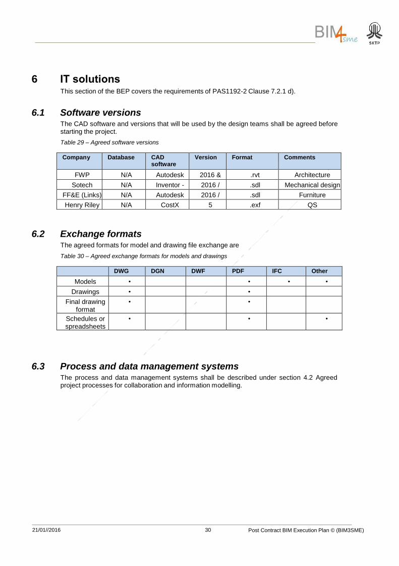
6.1 Software versions The CAD software and versions that will be used by the design teams shall be agreed before starting the project.
Table 29 – Agreed software versions
Company Database CAD software
Version Format Comments
FWP N/A Autodesk Revit
2016 & early
versions
.rvt Architecture
Sotech Optima
N/A Inventor - Pro /
Solidworks
2016 / 2016
.sdl Mechanical design / Cladding FF&E (Links) N/A Autodesk
Inventor/ Solidworks
2016 / 2016
.sdl Furniture
Henry Riley LLP
N/A CostX 5 .exf QS
6.2 Exchange formats The agreed formats for model and drawing file exchange are
Table 30 – Agreed exchange formats for models and drawings
DWG DGN DWF PDF IFC Other
Models • • • •
Drawings • •
Final drawing format
• •
Schedules or spreadsheets
• • •
6.3 Process and data management systems The process and data management systems shall be described under section 4.2 Agreed project processes for collaboration and information modelling.
21/01//2016 Post Contract BIM Execution Plan © (BIM3SME)
31
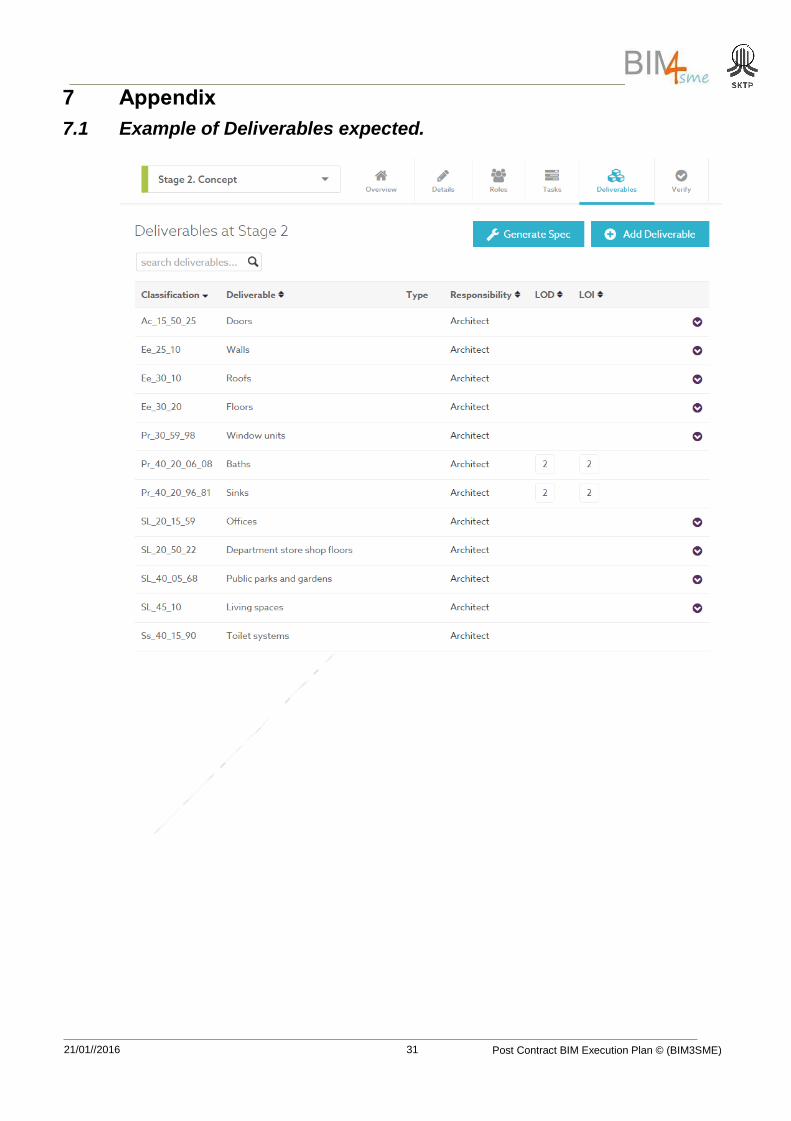
7 Appendix
7.1 Example of Deliverables expected.