Embed Size (px)
Citation preview
Materials and Chemistry 1
Post Combustion Capture
Dr. Thor Mejdell, SINTEFResearch manager CO2 Capture Processes
IEA GHG International CCS Summer School 2010Spitsbergen, 22-28 August

Materials and Chemistry 2
Main routes for CCS
Power plant Conventional
CO2capture
CoalOilNatural gas
CO2 storage
1
Gasification Reforming
Water-shift
CO2capture
Power plant Hydrogen-rich fuel2
Air separation Power plant Oxy-fuel combustion
Waterremoval
3
Exhaust, 0.3-0.5% CO2
Exhaust, 0.1-0.5% CO2
OHOH 222 22 ⇔+
COH +2 22 COH +
OHCOOCH 2224 2+⇔+
2O
Post combustion processes will probably be the main route for some time Are used today, existing power plants may easily be retrofitted. It will probably be too late to wait for new power stations. Normal lifetime 30 -50 years! May also be used on other large stationary emission points (industry)
Materials and Chemistry
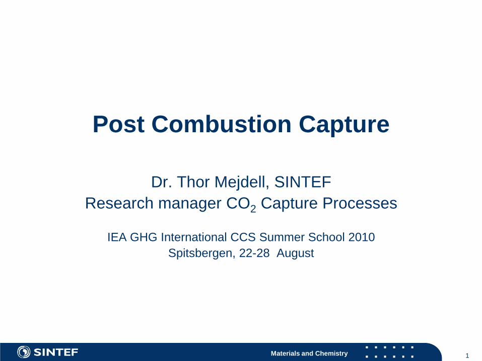
Post combustion technologies Because the partial pressure of CO2 in the exhaust gases
from power plants is very low (4 -12 kPa), a very limited number of technologies are feasible.
Absorption of CO2 with chemical reaction is practically the only feasible alternative today.
Possible alternatives on a longer term Membranes Adsorption onto porous particles with amine functionality
Note: If the exhaust gas is pressurized more technologies are feasible
3

Materials and Chemistry 4
A typical absorption capture process
Materials and Chemistry
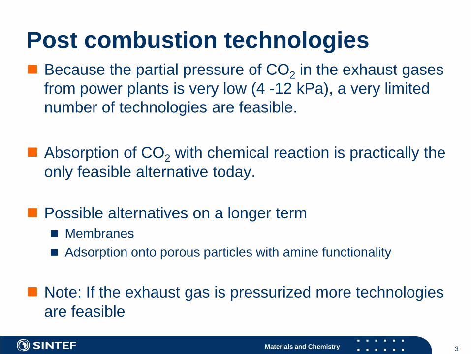
The CO2 is transferred from gas to liquid
H2O CO2(liquid) Ionicspecies
H2O CO2(gas)Gas
Liquid
Interface
Absorption of CO2 with chemical reaction
The amine reacts selectively with CO2
Materials and Chemistry
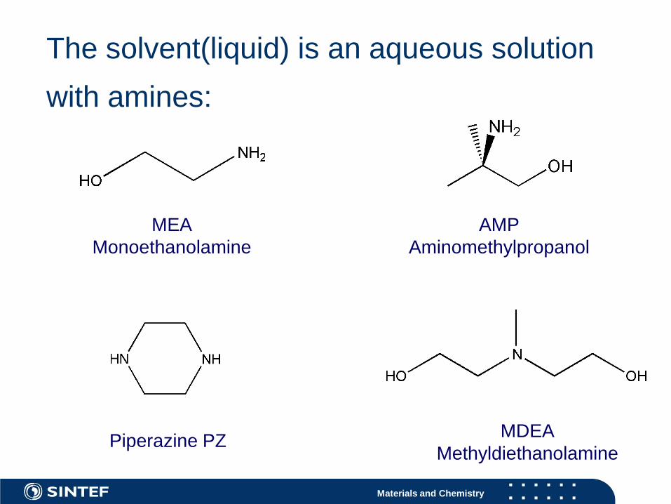
The solvent(liquid) is an aqueous solution with amines:
MEAMonoethanolamine
Piperazine PZ MDEAMethyldiethanolamine
AMPAminomethylpropanol

Materials and Chemistry
Reversible reactions:
−+ +↔+ RNHCOORNHlCORNH 322 )(2
)()( 22 lCOgCO ↔Dissolution of CO2 in solvent
Reversible reaction with amine to form carbamate
Key properties:Equilibrium constantsRate of reactionHeat of reaction
Materials and Chemistry 8
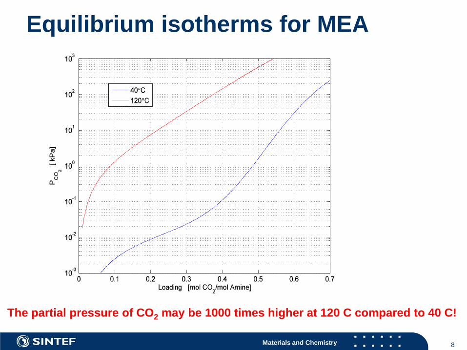
Equilibrium isotherms for MEA
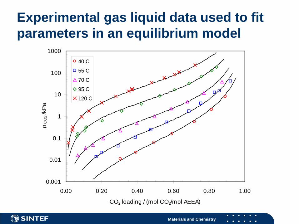
The partial pressure of CO2 may be 1000 times higher at 120 C compared to 40 C!
Materials and Chemistry 9
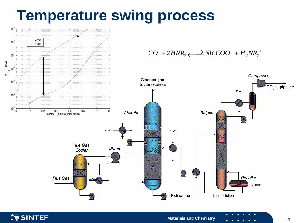
Temperature swing process
2 2 2 2 22CO HNR NR COO H NR− +→+ +←
Materials and Chemistry 10
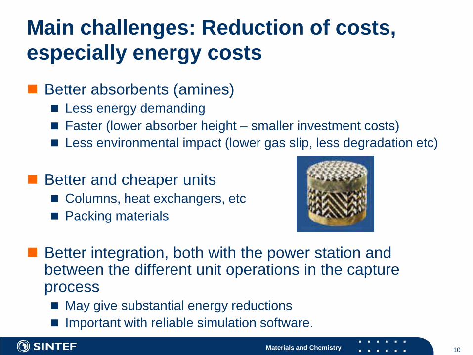
Main challenges: Reduction of costs, especially energy costs Better absorbents (amines)
Less energy demanding Faster (lower absorber height – smaller investment costs) Less environmental impact (lower gas slip, less degradation etc)
Better and cheaper units Columns, heat exchangers, etc Packing materials
Better integration, both with the power station and between the different unit operations in the capture process May give substantial energy reductions Important with reliable simulation software.
Materials and Chemistry 11
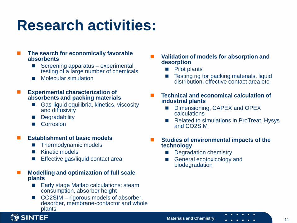
The search for economically favorable absorbents Screening apparatus – experimental
testing of a large number of chemicals Molecular simulation
Experimental characterization of absorbents and packing materials Gas-liquid equilibria, kinetics, viscosity
and diffusivity Degradability Corrosion
Establishment of basic models Thermodynamic models Kinetic models Effective gas/liquid contact area
Modelling and optimization of full scale plants Early stage Matlab calculations: steam
consumption, absorber height CO2SIM – rigorous models of absorber,
desorber, membrane-contactor and whole plants
Research activities:
Validation of models for absorption and desorption Pilot plants Testing rig for packing materials, liquid
distribution, effective contact area etc.
Technical and economical calculation of industrial plants Dimensioning, CAPEX and OPEX
calculations Related to simulations in ProTreat, Hysys
and CO2SIM
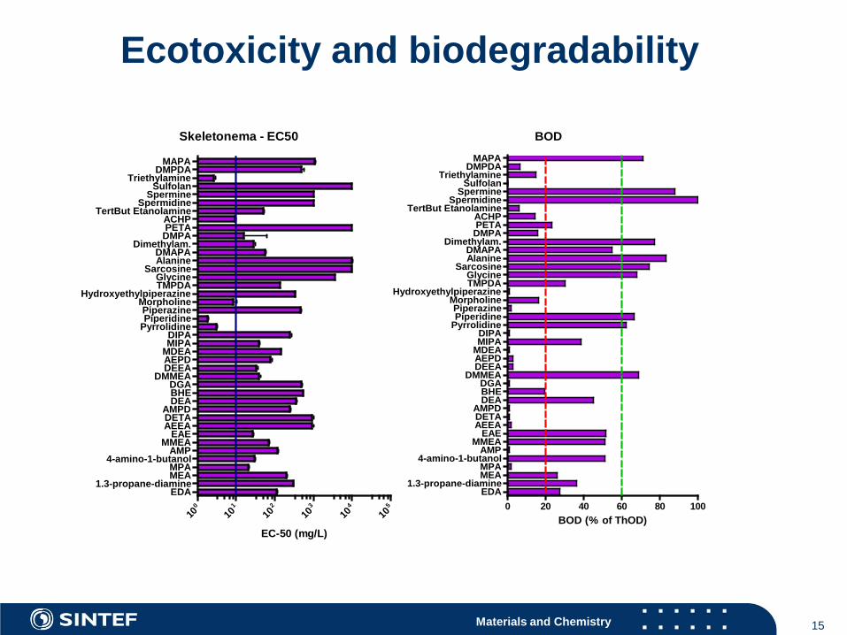
Studies of environmental impacts of the technology Degradation chemistry General ecotoxicology and
biodegradation
Materials and Chemistry
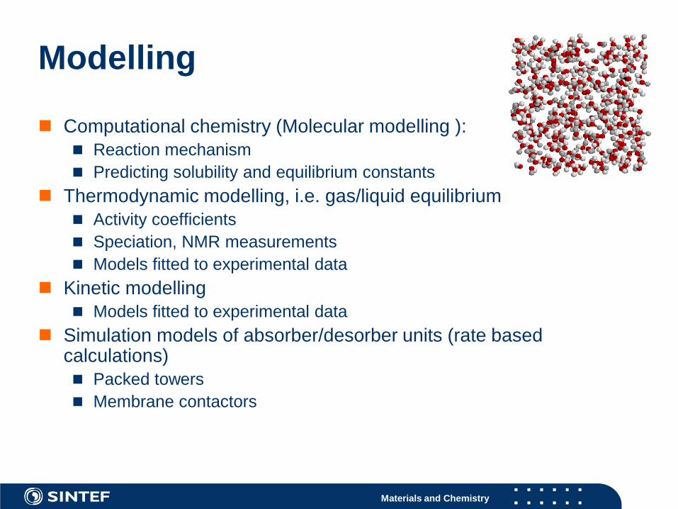
Modelling
Computational chemistry (Molecular modelling ): Reaction mechanism Predicting solubility and equilibrium constants
Thermodynamic modelling, i.e. gas/liquid equilibrium Activity coefficients Speciation, NMR measurements Models fitted to experimental data
Kinetic modelling Models fitted to experimental data
Simulation models of absorber/desorber units (rate based calculations) Packed towers Membrane contactors
Materials and Chemistry
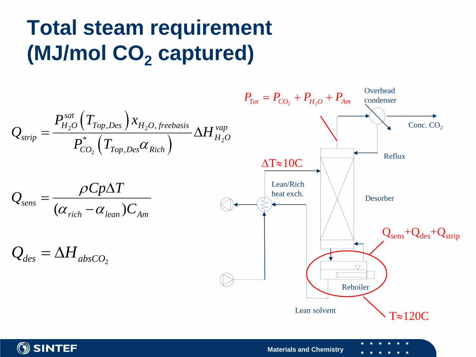
Total steam requirement (MJ/mol CO2 captured)
( )( )
2 2
2
2
, ,
*,
satH O Top Des H O freebasis vap
strip H OCO Top Des Rich
P T xQ H
P T α= ∆
2 2Tot CO H O AmP P P P= + +
( )sensrich lean Am
Cp TQC
ρα α
∆=
−
Conc. CO2
Reboiler
Overhead condenser
Lean/Rich heat exch.
Lean solvent
Desorber
Reflux
Qsens+Qdes+Qstrip
T≈120C
∆T≈10C
2des absCOQ H= ∆
Materials and Chemistry
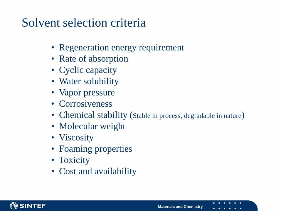
• Regeneration energy requirement• Rate of absorption• Cyclic capacity• Water solubility• Vapor pressure• Corrosiveness• Chemical stability (Stable in process, degradable in nature)• Molecular weight• Viscosity• Foaming properties• Toxicity• Cost and availability
Solvent selection criteria
Materials and Chemistry 15
Ecotoxicity and biodegradability
Skeletonema - EC50
100
101
102
103
104
105
EDA1.3-propane-diamine
MEAMPA
4-amino-1-butanolAMP
MMEAEAE
AEEADETAAMPD
DEABHEDGA
DMMEADEEAAEPDMDEAMIPADIPA
PyrrolidinePiperidinePiperazine
MorpholineHydroxyethylpiperazine
TMPDAGlycine
SarcosineAlanineDMAPA
Dimethylam.DMPAPETAACHP
TertBut EtanolamineSpermidine
SpermineSulfolan
TriethylamineDMPDA
MAPA
EC-50 (mg/L)
BOD
0 20 40 60 80 100EDA
1.3-propane-diamineMEAMPA
4-amino-1-butanolAMP
MMEAEAE
AEEADETAAMPD
DEABHEDGA
DMMEADEEAAEPDMDEAMIPADIPA
PyrrolidinePiperidinePiperazine
MorpholineHydroxyethylpiperazine
TMPDAGlycine
SarcosineAlanineDMAPA
Dimethylam.DMPAPETAACHP
TertBut EtanolamineSpermidine
SpermineSulfolan
TriethylamineDMPDA
MAPA
BOD (% of ThOD)
Materials and Chemistry
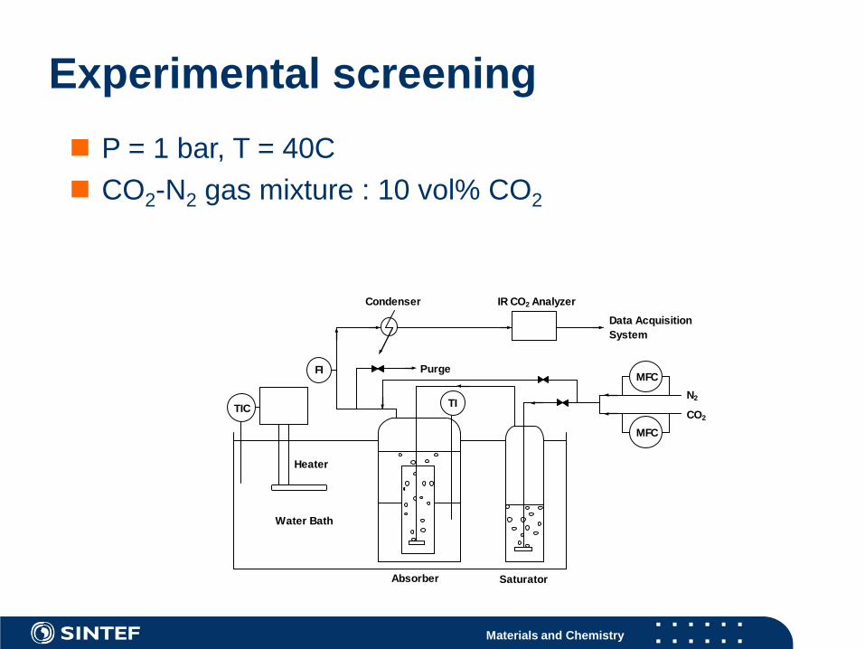
Experimental screening
N2
CO2
Water Bath
Absorber Saturator
Purge
IR CO2 AnalyzerCondenser
Data AcquisitionSystem
MFC
TIC TI
FI
Heater
MFC
P = 1 bar, T = 40C CO2-N2 gas mixture : 10 vol% CO2
Materials and Chemistry
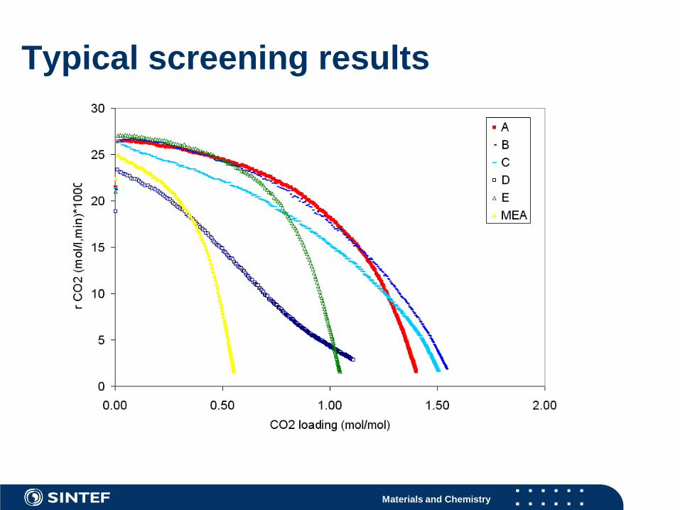
Typical screening results
Materials and Chemistry 18
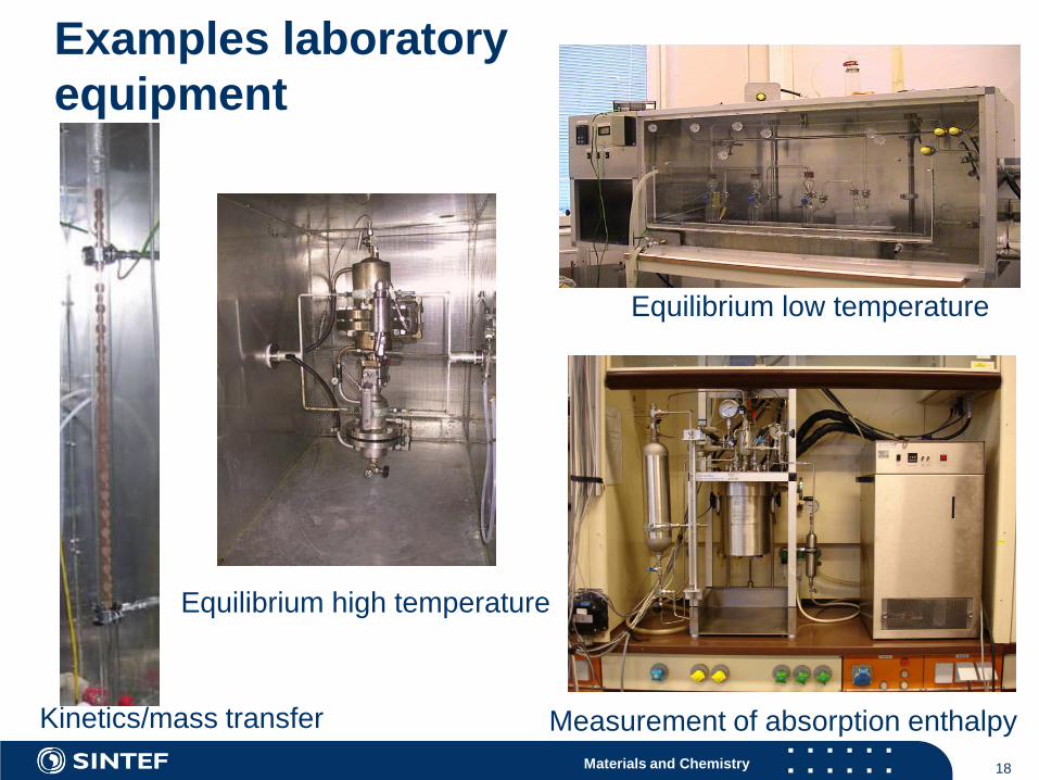
Examples laboratoryequipment
Equilibrium high temperature
Equilibrium low temperature
Measurement of absorption enthalpyKinetics/mass transfer
Materials and Chemistry
Experimental gas liquid data used to fit parameters in an equilibrium model
0.001
0.01
0.1
1
10
100
1000
0.00 0.20 0.40 0.60 0.80 1.00
CO2 loading / (mol CO2/mol AEEA)
pC
O2 /
kPa
40 C
55 C
70 C
95 C
120 C
Materials and Chemistry 20
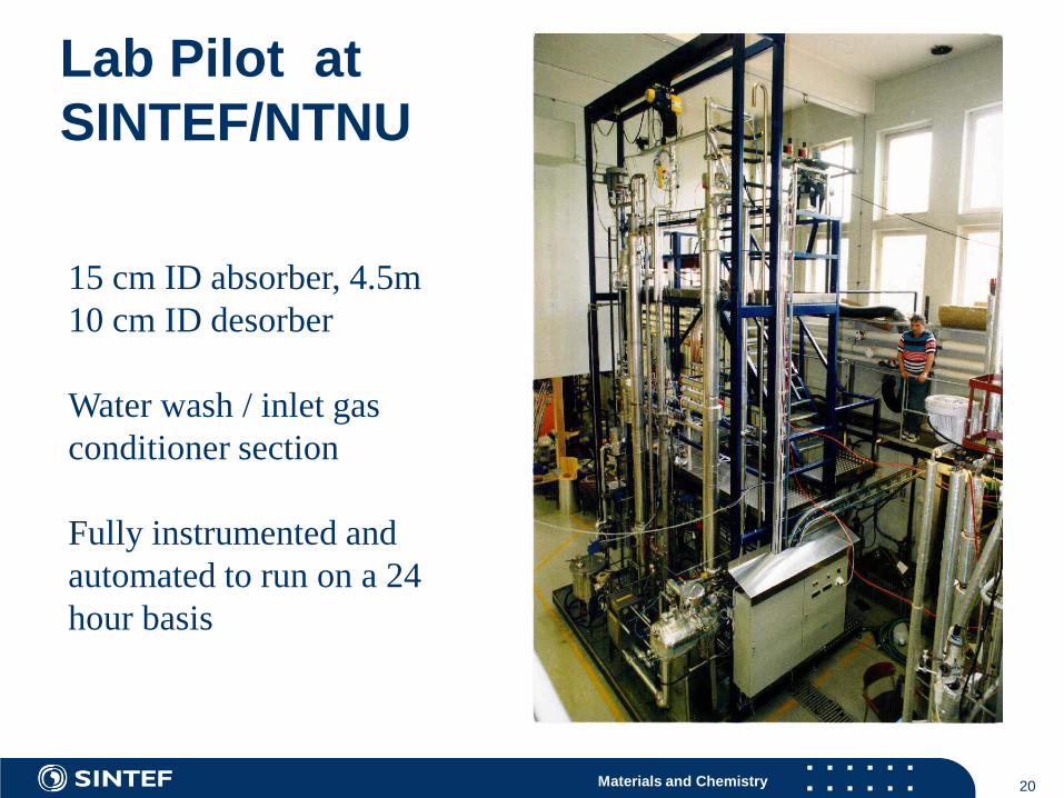
15 cm ID absorber, 4.5m10 cm ID desorber
Water wash / inlet gas conditioner section
Fully instrumented and automated to run on a 24 hour basis
Lab Pilot at SINTEF/NTNU
Materials and Chemistry 21

Materials and Chemistry 22
30m (11 floors) high SINTEF-building.
New Pilot plant at Tiller, Trondheim
Materials and Chemistry
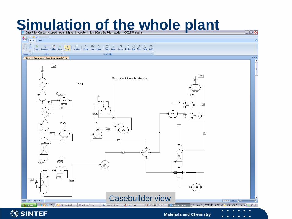
Casebuilder view
Simulation of the whole plant
Materials and Chemistry
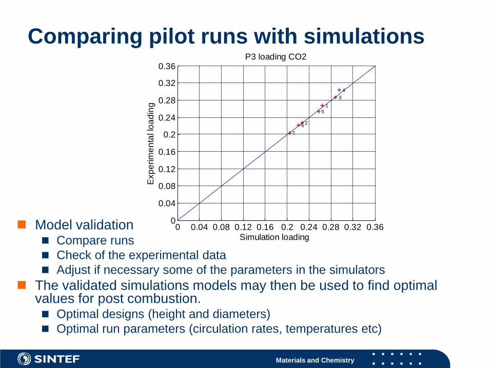
Comparing pilot runs with simulations
Model validation Compare runs Check of the experimental data Adjust if necessary some of the parameters in the simulators
The validated simulations models may then be used to find optimal values for post combustion. Optimal designs (height and diameters) Optimal run parameters (circulation rates, temperatures etc)
0 0.04 0.08 0.12 0.16 0.2 0.24 0.28 0.32 0.360
0.04
0.08
0.12
0.16
0.2
0.24
0.28
0.32
0.36P3 loading CO2
1
2
34
5
67
Exp
erim
enta
l loa
ding
Simulation loading
Materials and Chemistry
Optimization important for cost reductions
Optimizing criteria Minimum energy consumption (MJ/kg CO2 captured) Minimum total costs €/kg CO2 avoided (need then cost calulation
software.
The validated simulations models is used to find optimal values for the specific solvent. Optimal designs (height and diameters) Optimal run parameters (circulation rates, temperatures etc)
If possible, optimize the combined power & capture plant Heat integration may give lower energy consumption More complex process, the operability of the plant may be worse
Materials and Chemistry
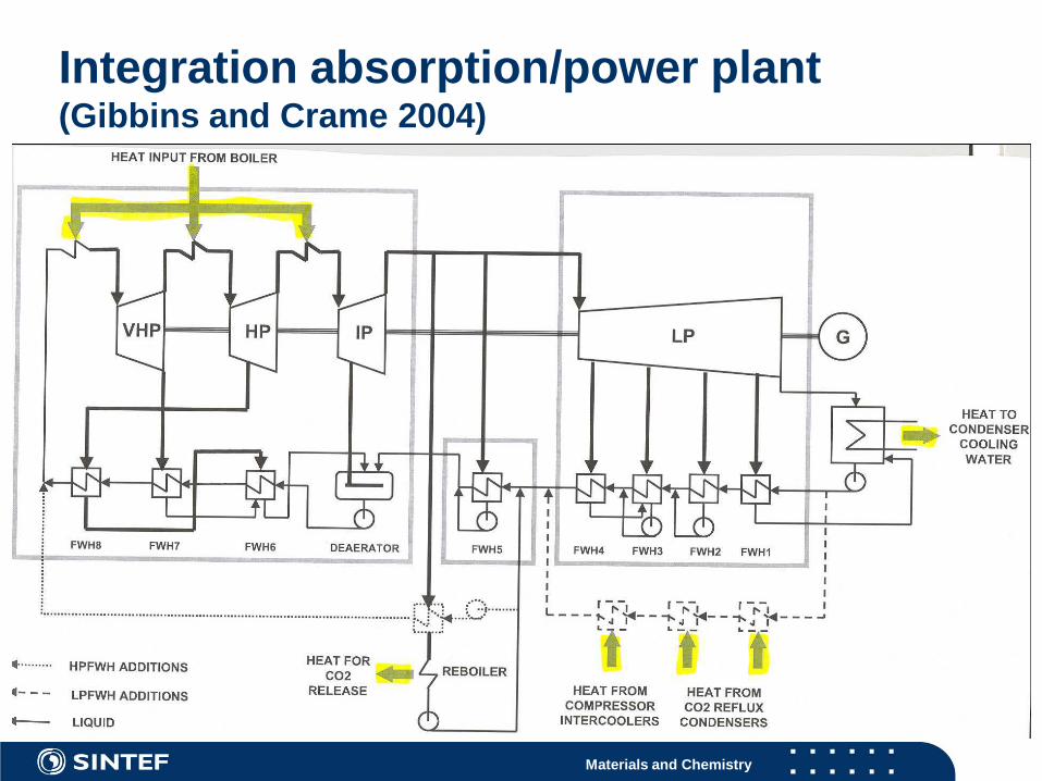
Integration absorption/power plant (Gibbins and Crame 2004)
Materials and Chemistry
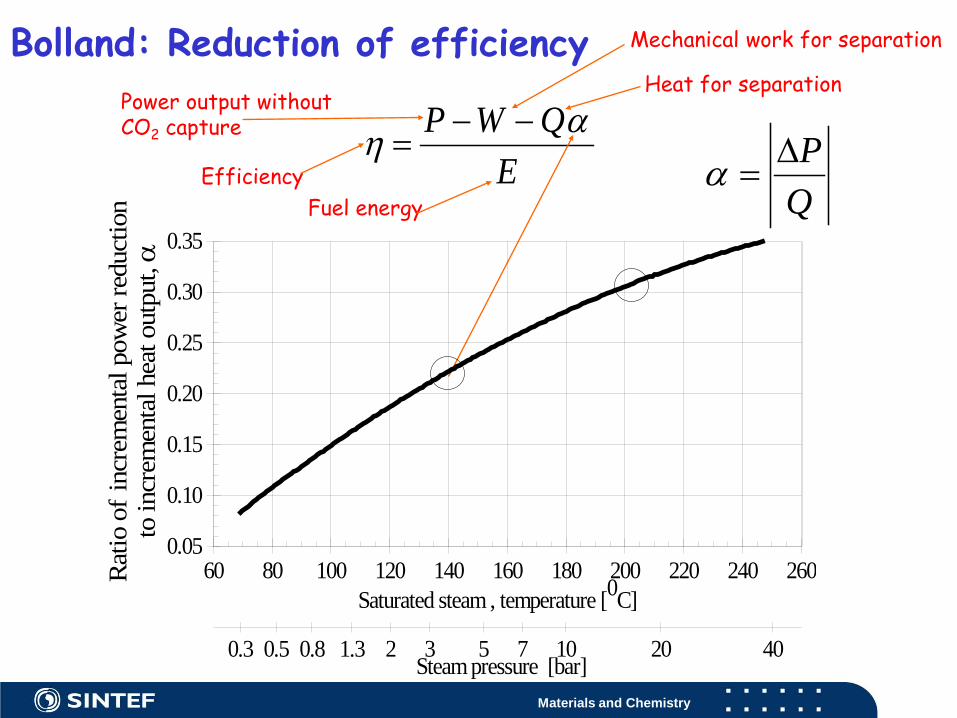
Bolland: Reduction of efficiency
EQWP αη −−
=Efficiency
Power output withoutCO2 capture
Mechanical work for separation
Heat for separation
Fuel energy QP∆
=α
60 80 100 120 140 160 180 200 220 240 260Saturated steam , temperature [0C]
0.05
0.10
0.15
0.20
0.25
0.30
0.35
Rat
io o
f in
crem
enta
l pow
er re
duct
ion
to in
crem
enta
l hea
t out
put, α
0.3 0.5 0.8 1.3 2 3 5 7 10 20 40Steam pressure [bar]

Materials and Chemistry
Absorber diameter of 50 or 75 cm Testing various absorber packings
Liquid distribution and pressure drop Efficient gas-liquid area Gas and liquid distribution Back mixing and entrainment
Better models for simulations
Gas-Liquid contactorsTest of different packings
Materials and Chemistry
CO2
Gas with CO2
CO2
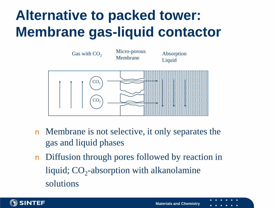
n Membrane is not selective, it only separates the gas and liquid phases
n Diffusion through pores followed by reaction in liquid; CO2-absorption with alkanolamine solutions
Micro-porous Membrane
Absorption Liquid
Alternative to packed tower: Membrane gas-liquid contactor
Materials and Chemistry
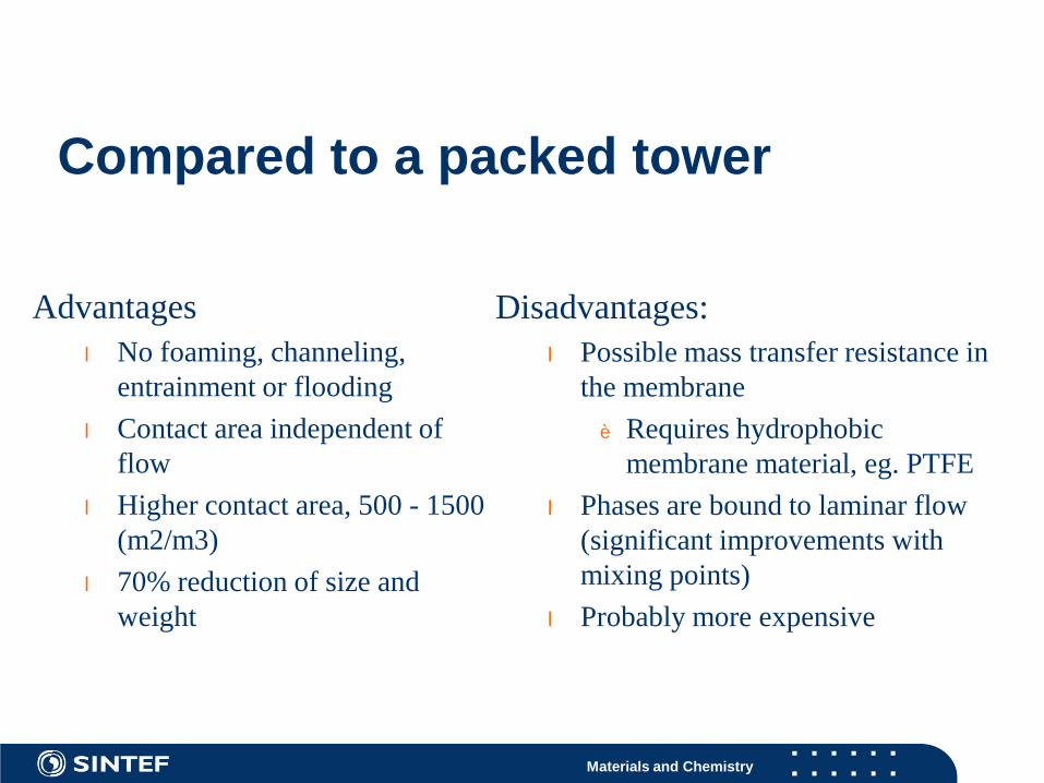
Advantagesl No foaming, channeling,
entrainment or floodingl Contact area independent of
flowl Higher contact area, 500 - 1500
(m2/m3) l 70% reduction of size and
weight
Compared to a packed tower
Disadvantages:l Possible mass transfer resistance in
the membraneè Requires hydrophobic
membrane material, eg. PTFEl Phases are bound to laminar flow
(significant improvements with mixing points)
l Probably more expensive
Materials and Chemistry
Other post combustion techniques
Membrane gas separation Adsorption
Advantage No transport of liquid phase
Disadvantage More complex process At the moment more costly
Materials and Chemistry
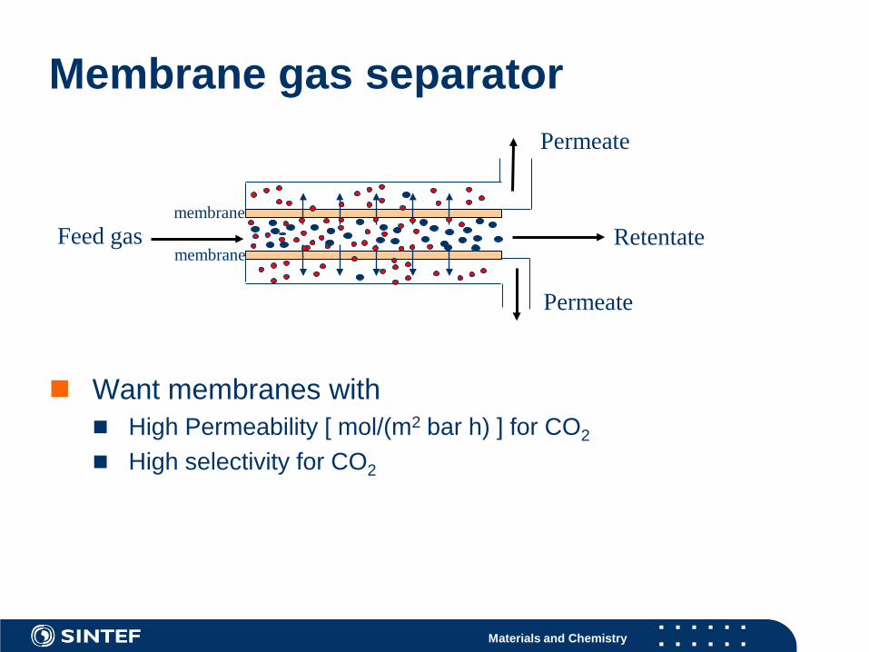
Membrane gas separator
Want membranes with High Permeability [ mol/(m2 bar h) ] for CO2
High selectivity for CO2
Feed gas Retentatemembrane
Permeate
Permeate
membrane
Materials and Chemistry
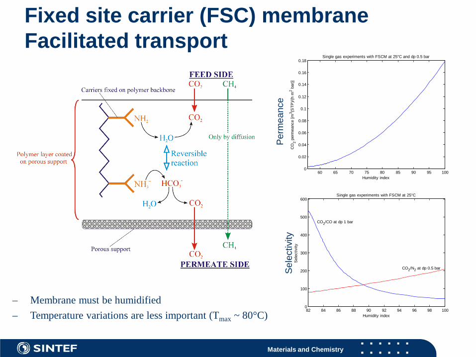
Fixed site carrier (FSC) membraneFacilitated transport
– Membrane must be humidified – Temperature variations are less important (Tmax ~ 80°C)
60 65 70 75 80 85 90 95 1000
0.02
0.04
0.06
0.08
0.1
0.12
0.14
0.16
0.18
Humidity index
CO
2 per
mea
nce
[m3 (S
TP)/(
h m
2 bar
)]
Single gas experiments with FSCM at 25°C and dp 0.5 bar
82 84 86 88 90 92 94 96 98 1000
100
200
300
400
500
600
Humidity index
Sel
ectiv
ity
Single gas experiments with FSCM at 25°C
CO2/CO at dp 1 bar
CO2/N2 at dp 0.5 bar
Per
mea
nce
Sel
ectiv
ity
Materials and Chemistry
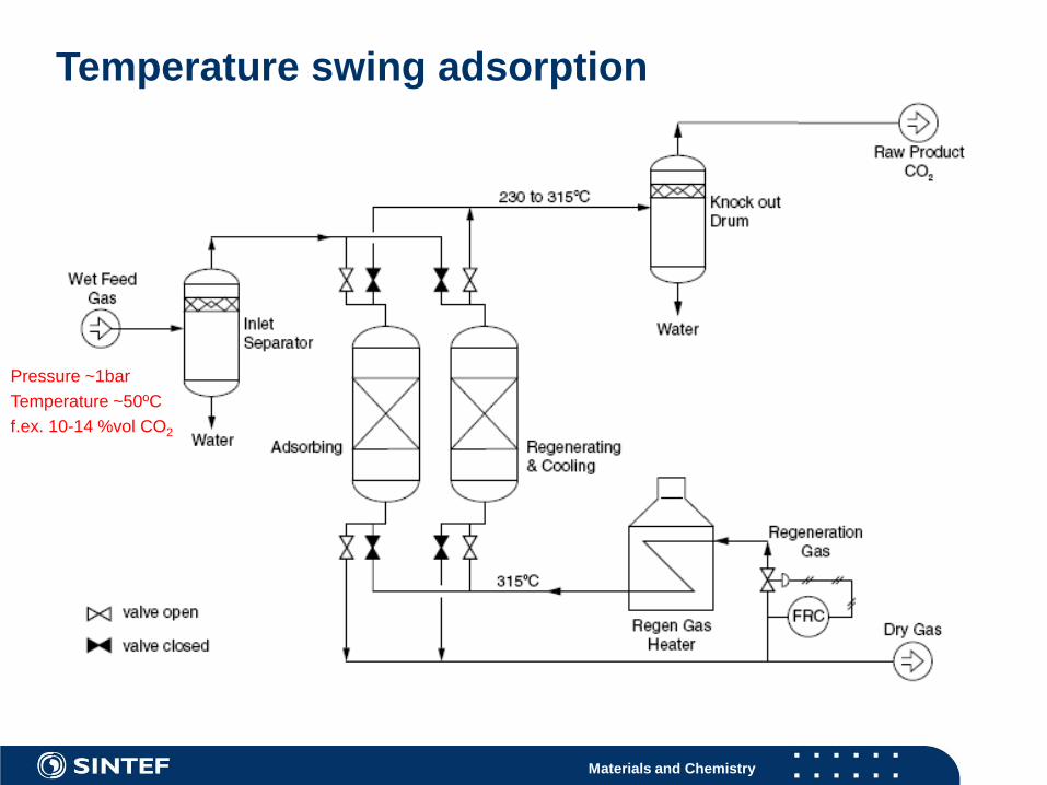
Temperature swing adsorption
Pressure ~1barTemperature ~50ºCf.ex. 10-14 %vol CO2

Materials and Chemistry
Aspects with adsorption for post comb
VPSA (Vacuum pressure swing adsorpion is probably not feasible, TSA is the only current option (or TSA+VPSA)
Cyclic capacity and adsorbent lifetime Pressure drop Moisture Heat transfer Valves

Materials and Chemistry
Summary
Post combustion is relatively easy to implement Absorption with chemical reaction is the preferred method Commercial bidders is available High consumption of thermal energy Research and development to reduce the energy penalty Better solvents
More energy efficient Less environmental impact
Process modeling and optimization is important for energy reduction
Materials and Chemistry
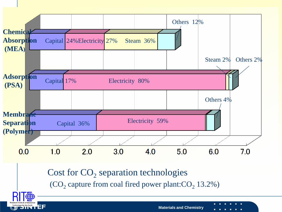
Chemical Absorption(MEA)
Adsorption(PSA)
Membrane Separation(Polymer)
Capital 36% Electricity 59%
Others 12%
Capital 17% Electricity 80%
Others 2%
Capital 24%Electricity 27% Steam 36%
Others 4%
Cost for CO2 separation technologies(CO2 capture from coal fired power plant:CO2 13.2%)
Steam 2%
Materials and Chemistry
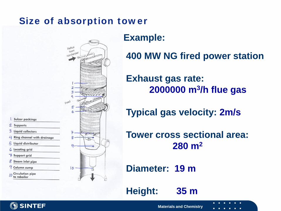
Size of absorption tower
Example:
400 MW NG fired power station
Exhaust gas rate:2000000 m3/h flue gas
Typical gas velocity: 2m/s
Tower cross sectional area:280 m2
Diameter: 19 m
Height: 35 m


![Peak Detection Implementation for Real-Time Signal ......(AMPD) method[1] has been introduced as an effective method. In this r e-search, we used the off-line and online terms to show](https://img.pdfslide.us/doc/110x75/612984cfe605c41e137dd992/peak-detection-implementation-for-real-time-signal-ampd-method1-has.jpg)