Embed Size (px)
Citation preview
Post-Buckling5.2.4
Post-buckled composite stiffened panel under shear
Buckling vs Post-buckling
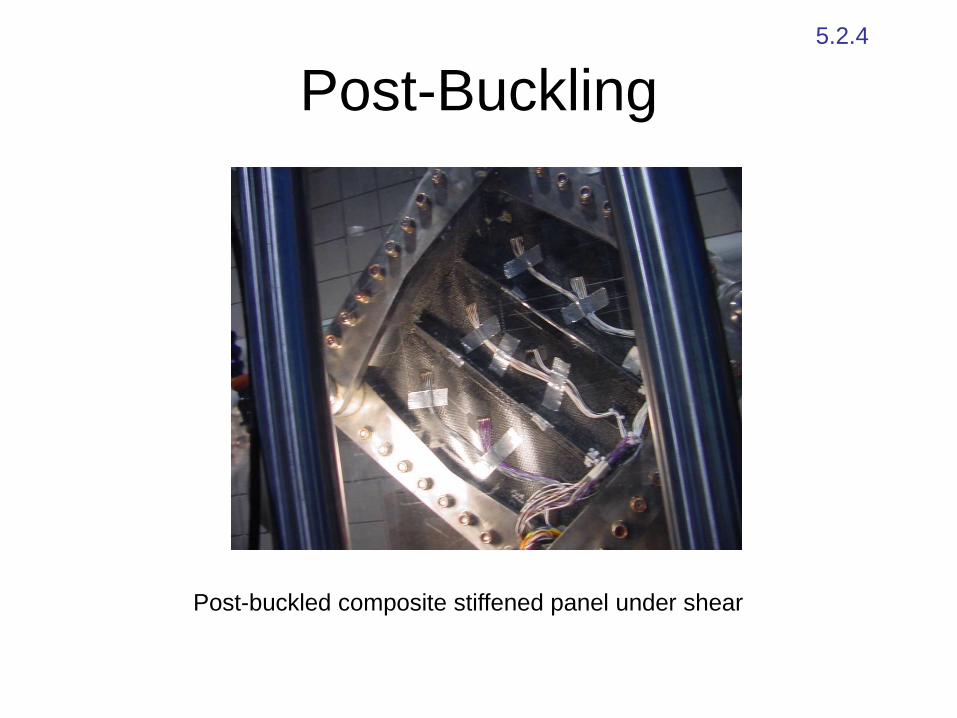
• in general buckling does not imply failure especially
for plates
P
Pcr
1
wcenter
beam post-buckling curve is flat and failure strains are reached at low
post-buckling loads
Buckling vs Post-buckling
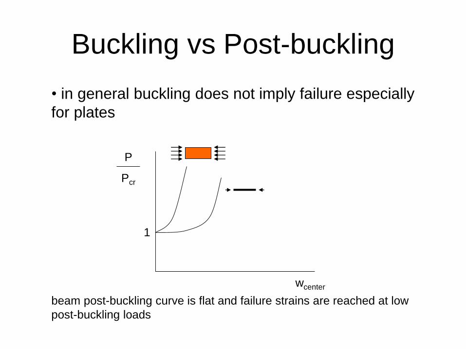
• post-buckled (stiffened) skins are significantly lighter
but have additional challenges:
– susceptible to skin/stiffener separation failure
where only resin holds the structure (unless
fasteners or other means are used to hold it together)
– susceptible to the creation and growth of
delamination under fatigue loading especially at high
post-buckling factors
skin/stiffener
separation
skin/stiffener
separation
skin/stiffener
separation
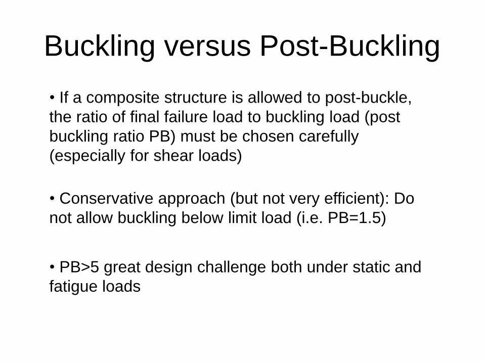
Buckling versus Post-Buckling
• If a composite structure is allowed to post-buckle,
the ratio of final failure load to buckling load (post
buckling ratio PB) must be chosen carefully
(especially for shear loads)
• Conservative approach (but not very efficient): Do
not allow buckling below limit load (i.e. PB=1.5)
• PB>5 great design challenge both under static and
fatigue loads
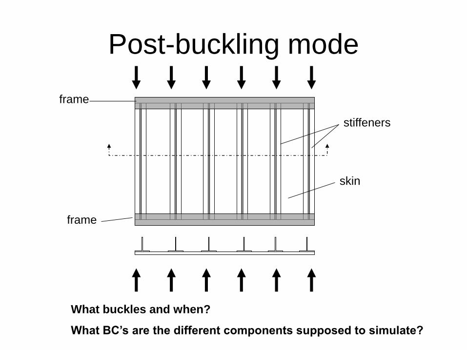
Post-buckling mode
frame
frame
stiffeners
skin
What buckles and when?
What BC’s are the different components supposed to simulate?
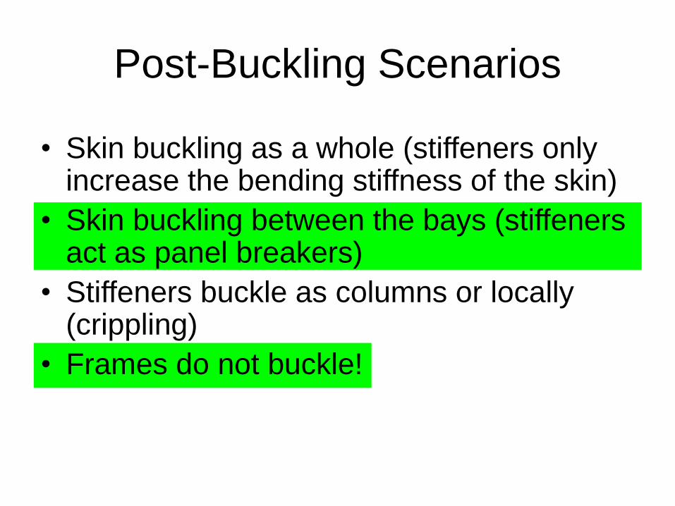
Post-Buckling Scenarios
• Skin buckling as a whole (stiffeners only increase the bending stiffness of the skin)
• Skin buckling between the bays (stiffeners act as panel breakers)
• Stiffeners buckle as columns or locally (crippling)
• Frames do not buckle!
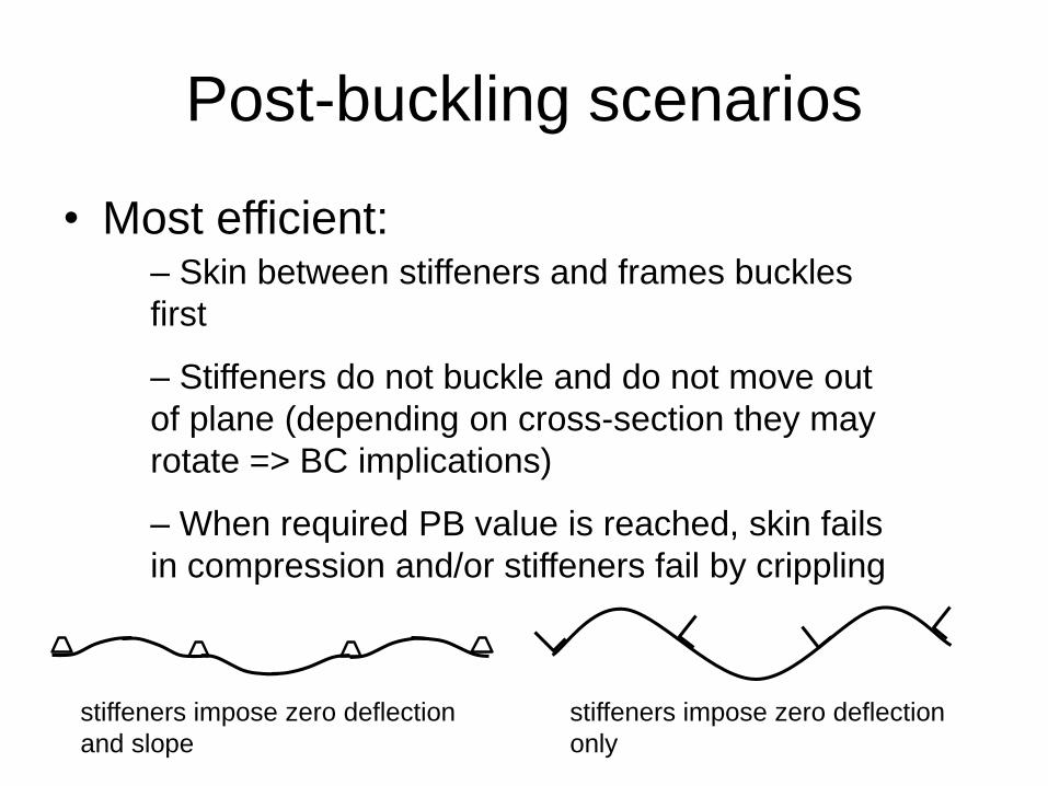
Post-buckling scenarios
• Most efficient:– Skin between stiffeners and frames buckles
first
– Stiffeners do not buckle and do not move out
of plane (depending on cross-section they may
rotate => BC implications)
– When required PB value is reached, skin fails
in compression and/or stiffeners fail by crippling
stiffeners impose zero deflection
and slope
stiffeners impose zero deflection
only
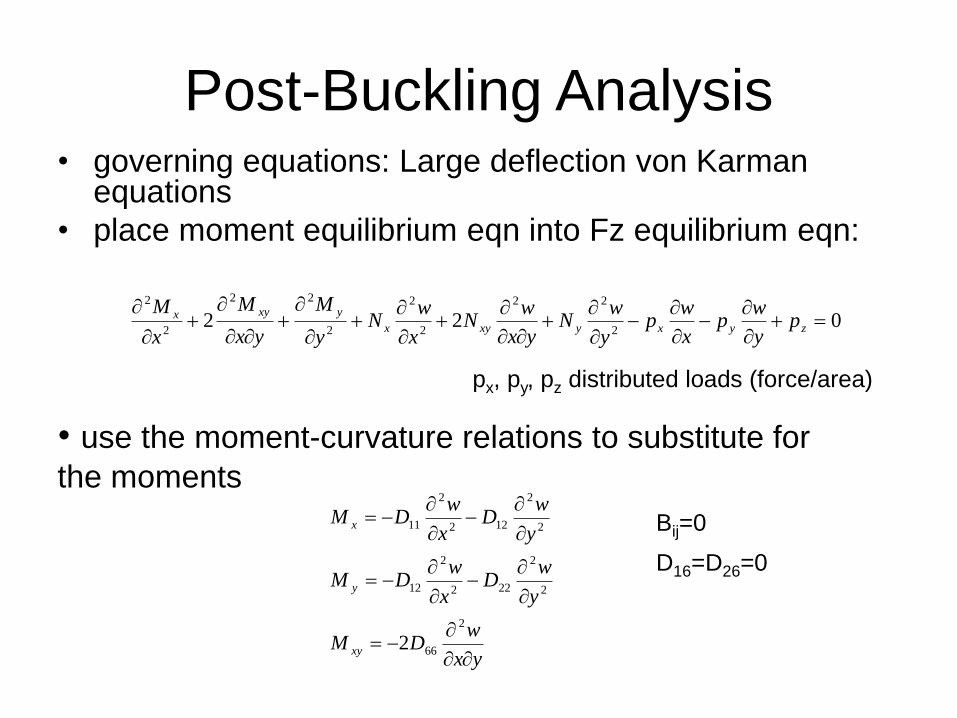
Post-Buckling Analysis• governing equations: Large deflection von Karman
equations
• place moment equilibrium eqn into Fz equilibrium eqn:
022
2
22
2
2
2
22
2
2
zyxyxyx
yxyx py
wp
x
wp
y
wN
yx
wN
x
wN
y
M
yx
M
x
M
px, py, pz distributed loads (force/area)
• use the moment-curvature relations to substitute for
the moments
D16=D26=0
Bij=0
yx
wDM
y
wD
x
wDM
y
wD
x
wDM
xy
y
x
2
66
2
2
222
2
12
2
2
122
2
11
2
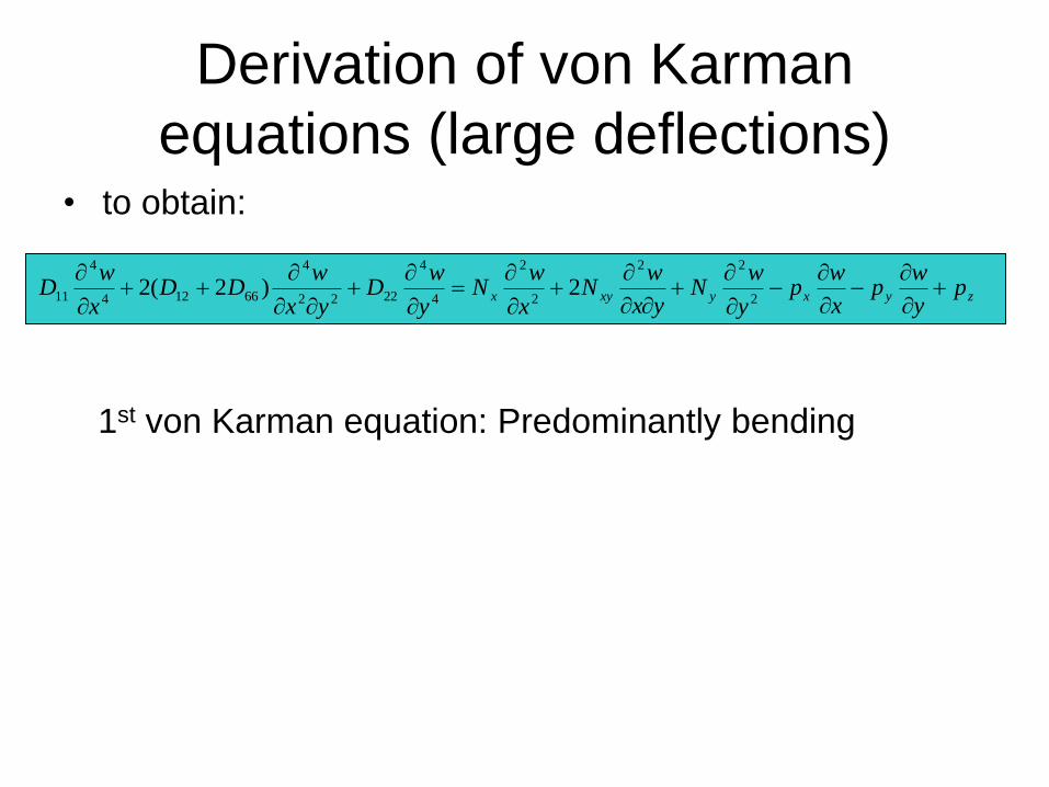
Derivation of von Karman
equations (large deflections)• to obtain:
1st von Karman equation: Predominantly bending
zyxyxyx p
y
wp
x
wp
y
wN
yx
wN
x
wN
y
wD
yx
wDD
x
wD
2
22
2
2
4
4
2222
4
66124
4
11 2)2(2
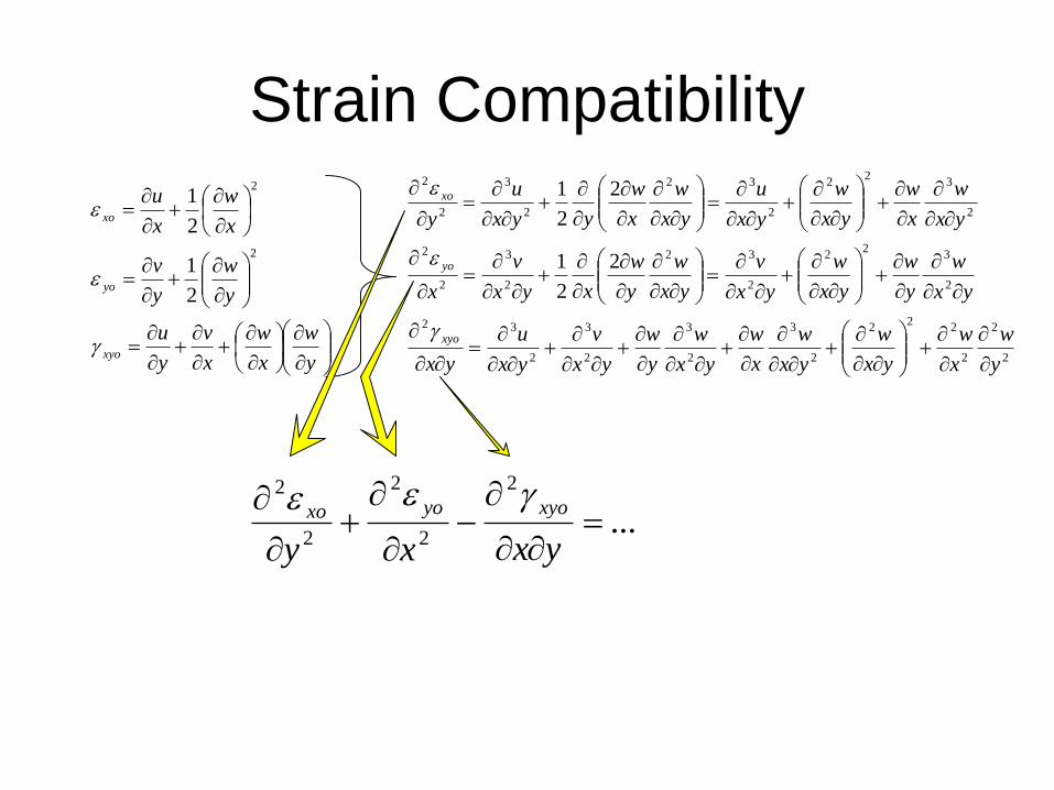
Strain Compatibility
y
w
x
w
x
v
y
u
y
w
y
v
x
w
x
u
xyo
yo
xo
2
2
2
1
2
1
2
2
2
22
2
2
3
2
3
2
3
2
32
2
32
2
2
32
2
3
2
2
2
32
2
2
32
2
3
2
2
2
2
1
2
2
1
y
w
x
w
yx
w
yx
w
x
w
yx
w
y
w
yx
v
yx
u
yx
yx
w
y
w
yx
w
yx
v
yx
w
y
w
xyx
v
x
yx
w
x
w
yx
w
yx
u
yx
w
x
w
yyx
u
y
xyo
yo
xo
...
2
2
2
2
2
yxxy
xyoyoxo
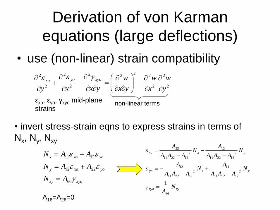
Derivation of von Karman
equations (large deflections)
• use (non-linear) strain compatibility
2
2
2
22
22
2
2
2
2
y
w
x
w
yx
w
yxxy
xyoyoxo
non-linear termsεxo, εyo, γxyo mid-plane
strains
• invert stress-strain eqns to express strains in terms of
Nx, Ny, Nxy
xyoxy
yoxoy
yoxox
AN
AAN
AAN
66
2212
1211
xyxyo
yxyo
yxxo
NA
NAAA
AN
AAA
A
NAAA
AN
AAA
A
66
2
122211
11
2
122211
12
2
122211
12
2
122211
22
1
A16=A26=0
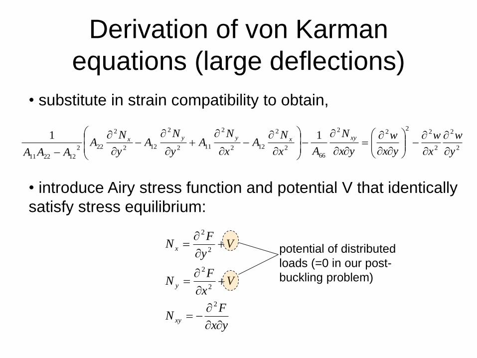
Derivation of von Karman
equations (large deflections)
• substitute in strain compatibility to obtain,
2
2
2
22
22
66
2
2
122
2
112
2
122
2
222
122211
11
y
w
x
w
yx
w
yx
N
Ax
NA
x
NA
y
NA
y
NA
AAA
xyxyyx
• introduce Airy stress function and potential V that identically
satisfy stress equilibrium:
yx
FN
Vx
FN
Vy
FN
xy
y
x
2
2
2
2
2
potential of distributed
loads (=0 in our post-
buckling problem)
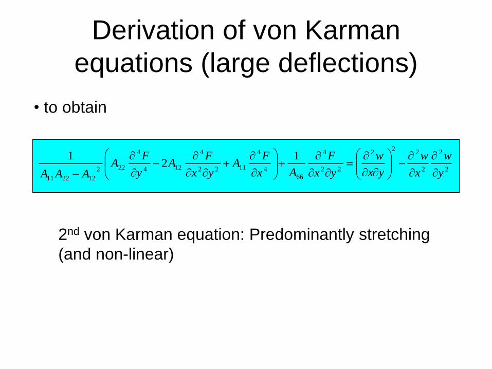
Derivation of von Karman
equations (large deflections)
• to obtain
2nd von Karman equation: Predominantly stretching
(and non-linear)
2
2
2
22
2
22
4
66
4
4
1122
4
124
4
222
122211
12
1
y
w
x
w
yx
w
yx
F
Ax
FA
yx
FA
y
FA
AAA
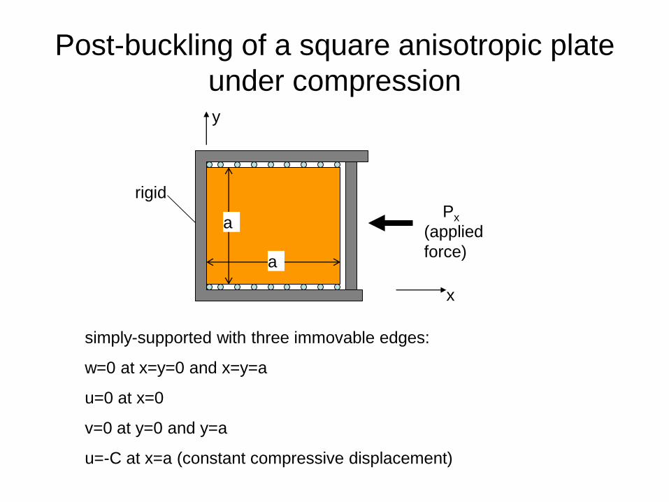
Post-buckling of a square anisotropic plate
under compression
simply-supported with three immovable edges:
w=0 at x=y=0 and x=y=a
u=0 at x=0
v=0 at y=0 and y=a
u=-C at x=a (constant compressive displacement)
a
a
Px
(applied
force)
rigid
x
y
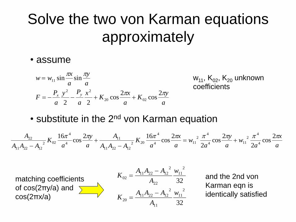
Solve the two von Karman equations
approximately
• assume
a
yK
a
xK
x
a
Py
a
PF
a
y
a
xww
yx
2cos
2cos
22
sinsin
0220
22
11
• substitute in the 2nd von Karman equation
a
x
aw
a
y
aw
a
x
aK
AAA
A
a
y
aK
AAA
A 2cos
2
2cos
2
2cos
162cos
164
42
114
42
114
4
202
122211
11
4
4
022
122211
22
w11, K02, K20 unknown
coefficients
32
32
2
11
11
2
12221120
2
11
22
2
12221102
w
A
AAAK
w
A
AAAK
matching coefficients
of cos(2πy/a) and
cos(2πx/a)
and the 2nd von
Karman eqn is
identically satisfied
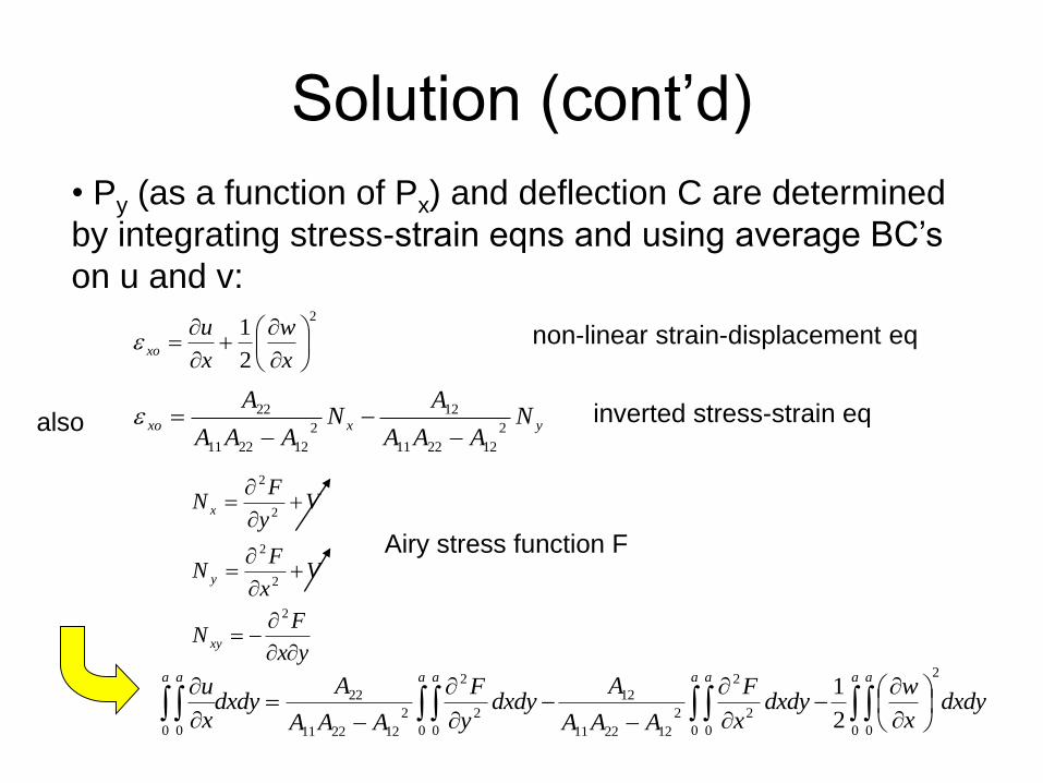
Solution (cont’d)
• Py (as a function of Px) and deflection C are determined
by integrating stress-strain eqns and using average BC’s
on u and v: 2
2
1
x
w
x
uxo
yxxo N
AAA
AN
AAA
A2
122211
12
2
122211
22
also
non-linear strain-displacement eq
inverted stress-strain eq
Airy stress function F
dxdy
x
wdxdy
x
F
AAA
Adxdy
y
F
AAA
Adxdy
x
ua aa aa aa a 2
0 00 0
2
2
2
122211
12
0 0
2
2
2
122211
22
0 02
1
yx
FN
Vx
FN
Vy
FN
xy
y
x
2
2
2
2
2
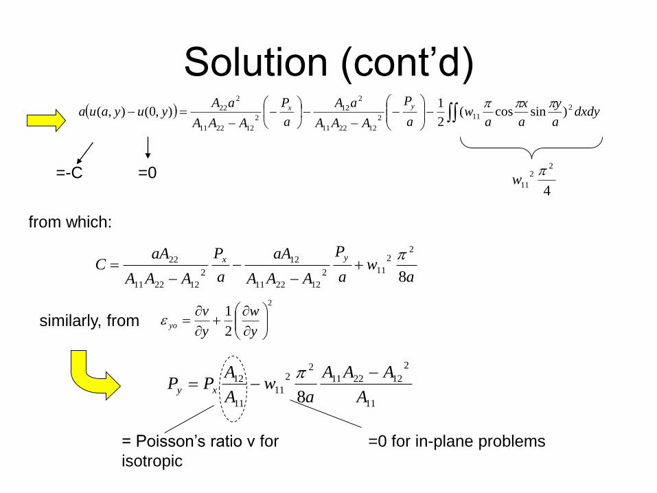
Solution (cont’d)
=-C =0
4
22
11
w
from which:
dxdy
a
y
a
x
aw
a
P
AAA
aA
a
P
AAA
aAyuyaua
yx 2
112
122211
2
12
2
122211
2
22 )sincos(2
1),0(),(
aw
a
P
AAA
aA
a
P
AAA
aAC
yx
8
22
112
122211
12
2
122211
22
similarly, from 2
2
1
y
w
y
vyo
= Poisson’s ratio ν for
isotropic
=0 for in-plane problems
11
2
122211
22
11
11
12
8 A
AAA
aw
A
APP xy
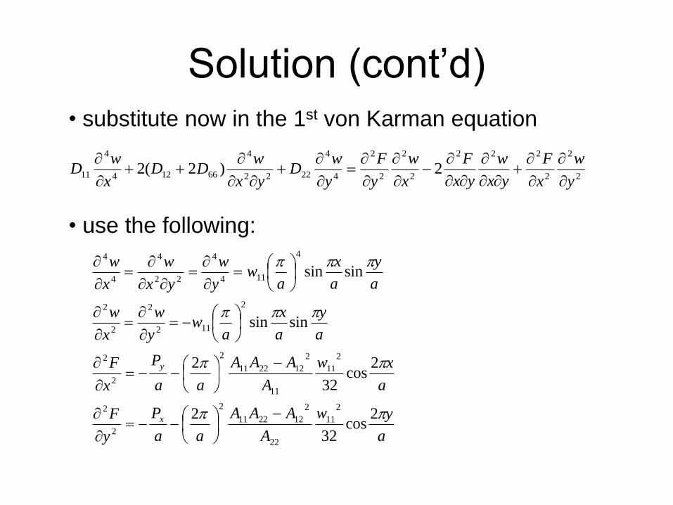
Solution (cont’d)
• substitute now in the 1st von Karman equation
2
2
2
222
2
2
2
2
4
4
2222
4
66124
4
11 2)2(2y
w
x
F
yx
w
yx
F
x
w
y
F
y
wD
yx
wDD
x
wD
• use the following:
a
yw
A
AAA
aa
P
y
F
a
xw
A
AAA
aa
P
x
F
a
y
a
x
aw
y
w
x
w
a
y
a
x
aw
y
w
yx
w
x
w
x
y
2cos
32
2
2cos
32
2
sinsin
sinsin
2
11
22
2
122211
2
2
2
2
11
11
2
122211
2
2
2
2
112
2
2
2
4
114
4
22
4
4
4
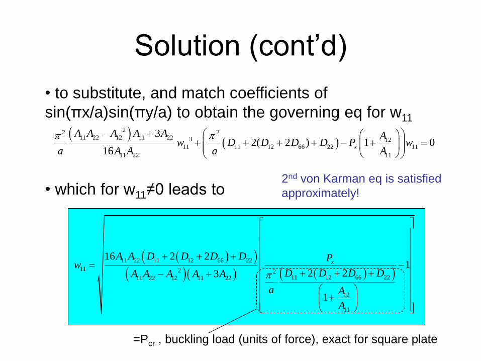
Solution (cont’d)
• to substitute, and match coefficients of
sin(πx/a)sin(πy/a) to obtain the governing eq for w11
• which for w11≠0 leads to
=Pcr , buckling load (units of force), exact for square plate
2nd von Karman eq is satisfied
approximately!
11 22 11 12 66 22
11 2 211 12 66 2211 22 12 11 22
12
11
16 2 21
2 23
1
xA A D D D D P
wD D D DA A A A A
a A
A
22 211 22 12 11 22 3 12
11 11 12 66 22 11
11 22 11
32( 2 ) 1 0
16x
A A A A A Aw D D D D P w
a A A a A
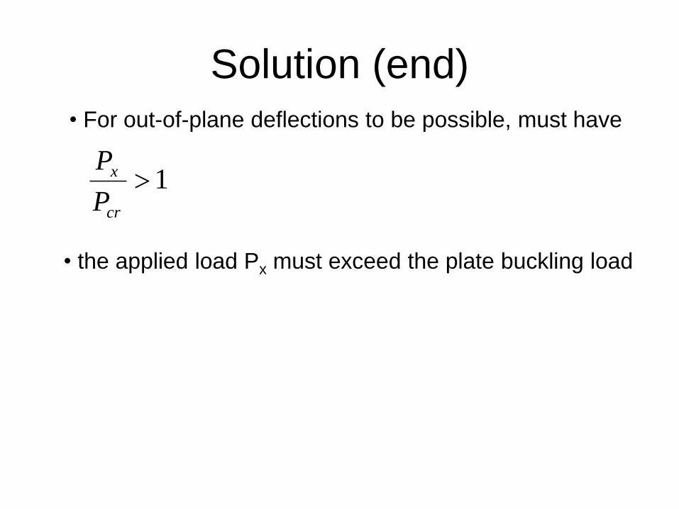
Solution (end)
• For out-of-plane deflections to be possible, must have
1
cr
x
P
P
• the applied load Px must exceed the plate buckling load
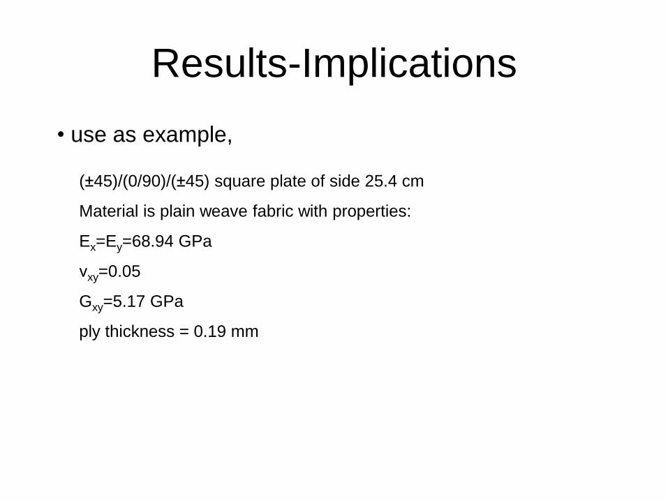
Results-Implications
• use as example,
(±45)/(0/90)/(±45) square plate of side 25.4 cm
Material is plain weave fabric with properties:
Ex=Ey=68.94 GPa
νxy=0.05
Gxy=5.17 GPa
ply thickness = 0.19 mm
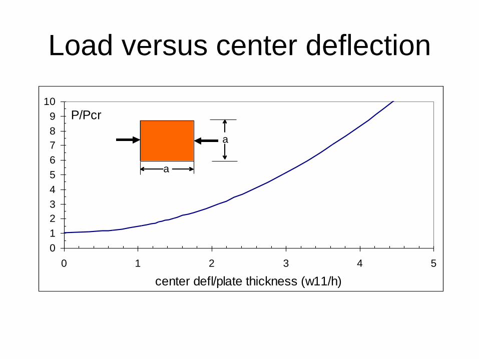
Load versus center deflection
0
1
2
3
4
5
6
7
8
9
10
0 1 2 3 4 5
center defl/plate thickness (w11/h)
P/Pcr
a
a
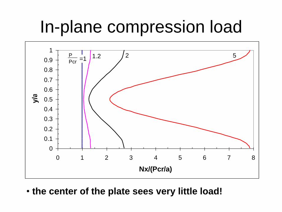
In-plane compression load
0
0.1
0.2
0.3
0.4
0.5
0.6
0.7
0.8
0.9
1
0 1 2 3 4 5 6 7 8
Nx/(Pcr/a)
y/a
=1P
Pcr1.2 2 5
• the center of the plate sees very little load!
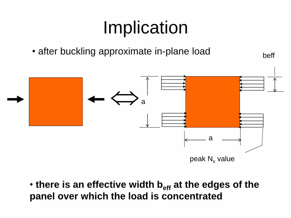
Implication
• after buckling approximate in-plane load
beff
a
a
peak Nx value
• there is an effective width beff at the edges of the
panel over which the load is concentrated
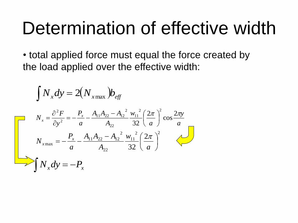
Determination of effective width
• total applied force must equal the force created by
the load applied over the effective width:
effxx bNdyN max2
a
y
a
w
A
AAA
a
P
y
FN x
x
2cos
2
32
22
11
22
2
122211
2
2
xx PdyN
22
11
22
2
122211max
2
32
a
w
A
AAA
a
PN x
x
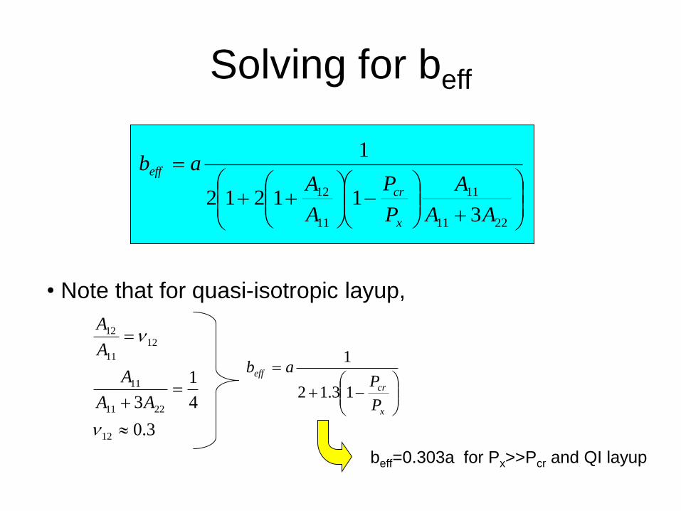
Solving for beff
2211
11
11
12
311212
1
AA
A
P
P
A
Aab
x
cr
eff
• Note that for quasi-isotropic layup,
x
cr
eff
P
Pab
13.12
1
beff=0.303a for Px>>Pcr and QI layup
3.0
4
1
3
12
2211
11
12
11
12
AA
A
A
A
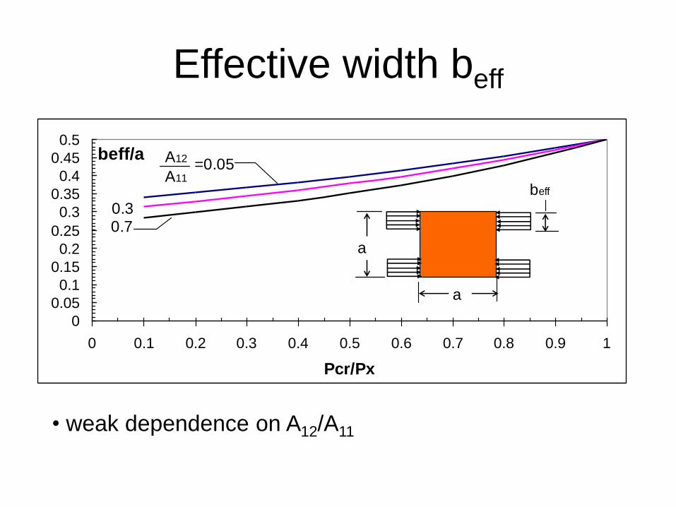
Effective width beff
0
0.05
0.1
0.15
0.2
0.25
0.3
0.35
0.4
0.45
0.5
0 0.1 0.2 0.3 0.4 0.5 0.6 0.7 0.8 0.9 1
Pcr/Px
beff/a
beff
a
a
A12
A11=0.05
0.30.7
• weak dependence on A12/A11
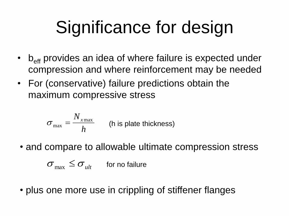
Significance for design
• beff provides an idea of where failure is expected under
compression and where reinforcement may be needed
• For (conservative) failure predictions obtain the
maximum compressive stress
h
N x maxmax (h is plate thickness)
• and compare to allowable ultimate compression stress
ult max for no failure
• plus one more use in crippling of stiffener flanges
How good is the analysis compared to
reality?
• For a meaningful comparison, two conditions must be
met:
– Boundary conditions in the “test case” must be the same as in
the model
– Sufficient number of terms must be included in the solution (as
opposed to only one term used here for simplicity)
• As it is hard to find test results with exactly these
boundary conditions, FE results are used to validate the
analysis
• Two different laminates: (a) 45 degree dominated
(b) Quasi-isotropic
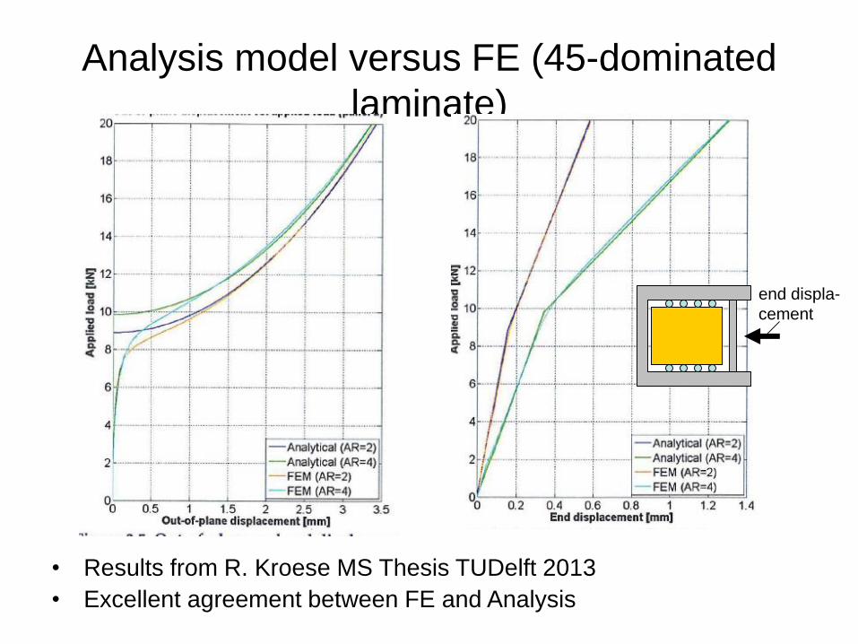
Analysis model versus FE (45-dominated
laminate)
• Results from R. Kroese MS Thesis TUDelft 2013
• Excellent agreement between FE and Analysis
end displa-
cement
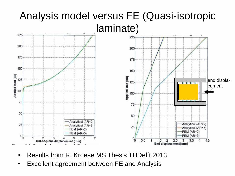
Analysis model versus FE (Quasi-isotropic
laminate)
• Results from R. Kroese MS Thesis TUDelft 2013
• Excellent agreement between FE and Analysis
end displa-
cement
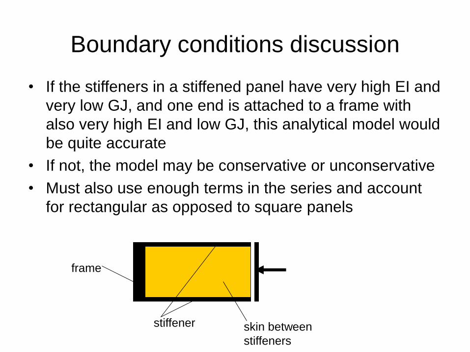
Boundary conditions discussion
• If the stiffeners in a stiffened panel have very high EI and
very low GJ, and one end is attached to a frame with
also very high EI and low GJ, this analytical model would
be quite accurate
• If not, the model may be conservative or unconservative
• Must also use enough terms in the series and account
for rectangular as opposed to square panels
stiffener
frame
skin between
stiffeners


![Buckling Analysis of Cold Formed Silo Column - · PDF fileBuckling Analysis of Cold Formed Silo Column Karol Rejowski ... Eurocode 3 [9] buckling formula for the silo design basing](https://img.pdfslide.us/doc/110x75/5a9dff167f8b9ada718c45e4/buckling-analysis-of-cold-formed-silo-column-analysis-of-cold-formed-silo-column.jpg)