Embed Size (px)
Citation preview
1American Institute of Aeronautics and Astronautics
AIAA 2002-1332
POST-BUCKLING TEST RESPONSE AND ANALYSIS OF FIBER COMPOSITE GRID-STIFFENED STRUCTURES
John E. Higgins Air Force Research Laboratory, VSSV
Kirtland AFB, NM USA
Peter M. Wegner Air Force Research Laboratory, VSSV
Kirtland AFB, NM USA
Barry Van West The Boeing Company
Seattle, WA, USA
Adrian Viisoreanu The Boeing Company
Seattle, WA, USA
ABSTRACT
A composite grid-stiffened cylindrically curved panel was fabricated and tested in static compression. Joint tension test coupons were fabricated from an unused portion of the panel construction and tested to failure in direct tension (rib/skin pull-off). Pre- and posttest analyses were performed to assess initial and overall buckling response. Comparisons to test data were made to assess: a) the influence of skin pocket buckling on overall structure response, b) the predictability of overall structure response through the range of operational load application, and c) probable causes of failure in this test panel and in future tests with rib and skin configuration optimized for specific spacecraft fairing applications.
INTRODUCTION
Composite grid-stiffened structures are less expensive to fabricate than widely used honeycomb-core structures. Weight benefits, damage tolerance, and recent innovations in tooling and manufacturing have lead to fabrication and static testing of curved panel designs suitable for spacecraft fairing applications. Boeing and the Air Force Research Laboratory/Space Vehicles Directorate (AFRL/VS) have fabricated
demonstration structures and conducted static load tests of partial cylinder panels, as well as material and joint coupon test specimens (Wegner, 2002.). Weight goals for the fairing encourage reliance on the rib grid to carry the majority of load with a minimal skin provided to enclose the payload and hold the shape of the rib grid. Because the proposed skin thickness for these structures is very small (ranging from .4572 to 1.168 mm), there is a tendency for the skin to exhibit post-buckling behavior at loads well below peak flight loads. The results of both testing and analysis suggest that effective use of this structure design type can be optimized with careful attention to post-buckling response and joint strength.
This paper will focus on aspects of structural performance of grid-stiffened construction that are relevant to fairing applications. First, extensive skin buckling is predicted and observed for these structures when subjected to increasing compression loads. It is important to understand that skin buckling increases in a gradual, predictable manner and that in the tested point design this buckling has only secondary impact on overall fairing response. Second, the primary structure response must be well understood and predictable to loads approaching the failure load. Factors of safety in fairing design typically account for overloads of not more that 25 percent. Third, the nature of the overall
This paper is declared a work of the US Government and is not subject to copyright protection in the United States.
AIAA 2002-1332
Report Documentation Page Form ApprovedOMB No. 0704-0188
Public reporting burden for the collection of information is estimated to average 1 hour per response, including the time for reviewing instructions, searching existing data sources, gathering andmaintaining the data needed, and completing and reviewing the collection of information. Send comments regarding this burden estimate or any other aspect of this collection of information,including suggestions for reducing this burden, to Washington Headquarters Services, Directorate for Information Operations and Reports, 1215 Jefferson Davis Highway, Suite 1204, ArlingtonVA 22202-4302. Respondents should be aware that notwithstanding any other provision of law, no person shall be subject to a penalty for failing to comply with a collection of information if itdoes not display a currently valid OMB control number.
1. REPORT DATE 01 APR 2002
2. REPORT TYPE N/A
3. DATES COVERED -
4. TITLE AND SUBTITLE Post-Buckling Test Response And Analysis Of Fiber CompositeGrid-Stiffened Structures
5a. CONTRACT NUMBER
5b. GRANT NUMBER
5c. PROGRAM ELEMENT NUMBER
6. AUTHOR(S) 5d. PROJECT NUMBER
5e. TASK NUMBER
5f. WORK UNIT NUMBER
7. PERFORMING ORGANIZATION NAME(S) AND ADDRESS(ES) Air Force Research Laboratory, VSSV Kirtland AFB, NM USA
8. PERFORMING ORGANIZATIONREPORT NUMBER
9. SPONSORING/MONITORING AGENCY NAME(S) AND ADDRESS(ES) 10. SPONSOR/MONITOR’S ACRONYM(S)
11. SPONSOR/MONITOR’S REPORT NUMBER(S)
12. DISTRIBUTION/AVAILABILITY STATEMENT Approved for public release, distribution unlimited
13. SUPPLEMENTARY NOTES
14. ABSTRACT
15. SUBJECT TERMS
16. SECURITY CLASSIFICATION OF: 17. LIMITATION OF ABSTRACT
UU
18. NUMBEROF PAGES
11
19a. NAME OFRESPONSIBLE PERSON
a. REPORT unclassified
b. ABSTRACT unclassified
c. THIS PAGE unclassified
Standard Form 298 (Rev. 8-98) Prescribed by ANSI Std Z39-18
2American Institute of Aeronautics and Astronautics
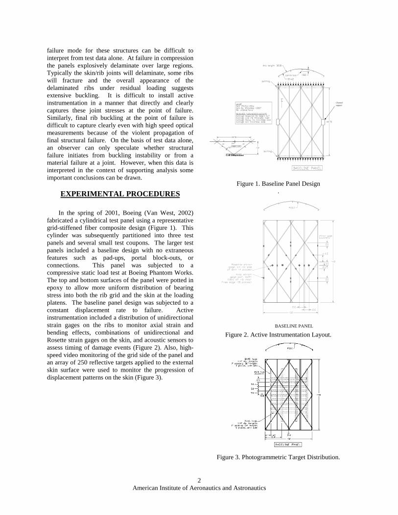
failure mode for these structures can be difficult to interpret from test data alone. At failure in compression the panels explosively delaminate over large regions. Typically the skin/rib joints will delaminate, some ribs will fracture and the overall appearance of the delaminated ribs under residual loading suggests extensive buckling. It is difficult to install active instrumentation in a manner that directly and clearly captures these joint stresses at the point of failure. Similarly, final rib buckling at the point of failure is difficult to capture clearly even with high speed optical measurements because of the violent propagation of final structural failure. On the basis of test data alone, an observer can only speculate whether structural failure initiates from buckling instability or from a material failure at a joint. However, when this data is interpreted in the context of supporting analysis some important conclusions can be drawn.
EXPERIMENTAL PROCEDURES
In the spring of 2001, Boeing (Van West, 2002) fabricated a cylindrical test panel using a representative grid-stiffened fiber composite design (Figure 1). This cylinder was subsequently partitioned into three test panels and several small test coupons. The larger test panels included a baseline design with no extraneous features such as pad-ups, portal block-outs, or connections. This panel was subjected to a compressive static load test at Boeing Phantom Works. The top and bottom surfaces of the panel were potted in epoxy to allow more uniform distribution of bearing stress into both the rib grid and the skin at the loading platens. The baseline panel design was subjected to a constant displacement rate to failure. Active instrumentation included a distribution of unidirectional strain gages on the ribs to monitor axial strain and bending effects, combinations of unidirectional and Rosette strain gages on the skin, and acoustic sensors to assess timing of damage events (Figure 2). Also, high-speed video monitoring of the grid side of the panel and an array of 250 reflective targets applied to the external skin surface were used to monitor the progression of displacement patterns on the skin (Figure 3).
Figure 1. Baseline Panel Design .
Figure 2. Active Instrumentation Layout.
Figure 3. Photogrammetric Target Distribution.
Cell Dimensions
Channelsupport
BASELINE PANEL
3American Institute of Aeronautics and Astronautics
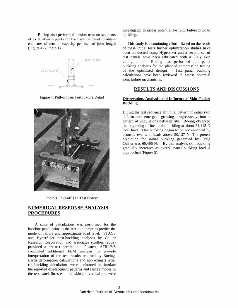
Boeing also performed tension tests on segments
of axial rib/skin joints for the baseline panel to obtain estimates of tension capacity per inch of joint length (Figure 4 & Photo 1).
Figure 4. Pull-off Tee Test Fixture Detail
Photo 1. Pull-off Tee Test Fixture
NUMERICAL RESPONSE ANALYSIS PROCEDURES
A suite of calculations was performed for the baseline panel prior to the test to attempt to predict the mode of failure and approximate load level. STAGS and HyperSizer post-buckling analyses by Collier Research Corporation and associates (Collier, 2002) provided a pre-test prediction. Posttest, AFRL/VS conducted additional FEM analysis to provide interpretation of the test results reported by Boeing. Large deformation calculations and approximate axial rib buckling calculations were performed to simulate the reported displacement patterns and failure modes in the test panel. Stresses in the skin and vertical ribs were
investigated to assess potential for joint failure prior to buckling.
This study is a continuing effort. Based on the result of these initial tests further optimization studies have been conducted using Hypersizer and a second set of test panels have been fabricated with a 3-ply skin configuration. Boeing has performed full panel buckling analyses for the planned compression testing of the optimized designs. Test panel buckling calculations have been reviewed to assess potential joint failure mechanisms.
RESULTS AND DISCUSSIONS
Observation, Analysis, and Influence of Skin Pocket Buckling:
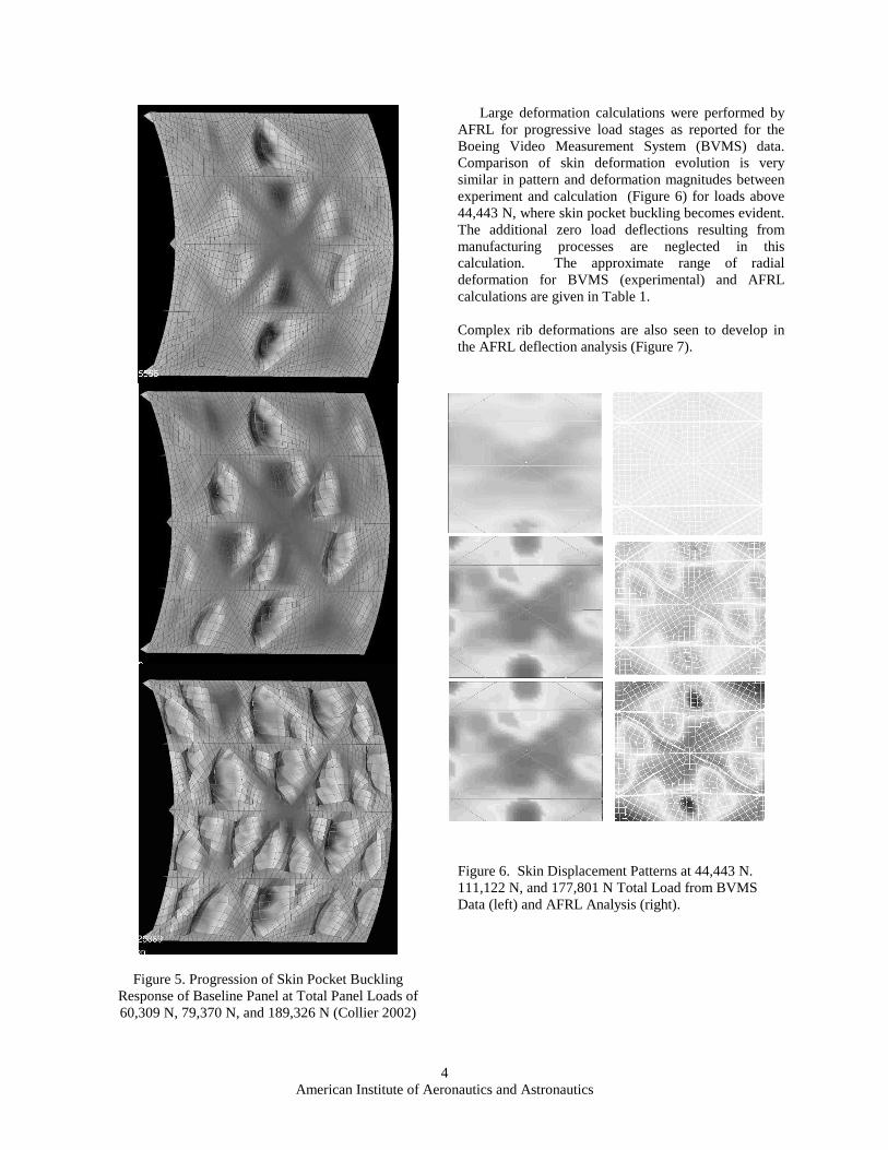
During the test sequence an initial pattern of radial skin deformation emerged, growing progressively into a pattern of undulations between ribs. Boeing observed the beginning of local skin buckling at about 31,115 N total load. This buckling began to be accompanied by acoustic events at loads above 50,137 N. The pretest prediction for initial buckling generated by Craig Collier was 60,466 N. By this analysis skin buckling gradually increases as overall panel buckling load is approached (Figure 5).
4American Institute of Aeronautics and Astronautics
Figure 5. Progression of Skin Pocket Buckling Response of Baseline Panel at Total Panel Loads of 60,309 N, 79,370 N, and 189,326 N (Collier 2002)
Large deformation calculations were performed by AFRL for progressive load stages as reported for the Boeing Video Measurement System (BVMS) data. Comparison of skin deformation evolution is very similar in pattern and deformation magnitudes between experiment and calculation (Figure 6) for loads above 44,443 N, where skin pocket buckling becomes evident. The additional zero load deflections resulting from manufacturing processes are neglected in this calculation. The approximate range of radial deformation for BVMS (experimental) and AFRL calculations are given in Table 1. Complex rib deformations are also seen to develop in the AFRL deflection analysis (Figure 7).
Figure 6. Skin Displacement Patterns at 44,443 N. 111,122 N, and 177,801 N Total Load from BVMS Data (left) and AFRL Analysis (right).
5American Institute of Aeronautics and Astronautics
Table 1. Approximate Range of Radial Deformations Illustrated in Figure 5.
Total Load
(N)
BVMS Data
(mm)
NASTRAN Calculation
(mm) 44,443 0.0 to 4.06 -.508 to .254 111,122 -5.08 to
5.08 -7.37 to 1.78
177,801 -5.84 to 6.35
-9.65 to 3.56
Figure 7. Circumferential Displacement Fringe from AFRL Analysis (10x) at 177,801 N Panel Load at the Location of the Initial Buckle in the Test
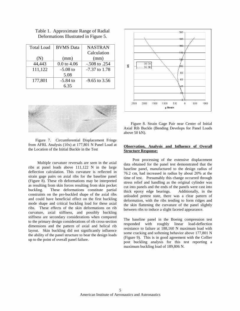
Multiple curvature reversals are seen in the axial ribs at panel loads above 111,122 N in the large deflection calculation. This curvature is reflected in strain gage pairs on axial ribs for the baseline panel (Figure 8). These rib deformations may be interpreted as resulting from skin forces resulting from skin pocket buckling. These deformations constitute partial constraints on the pre-buckled shape of the axial ribs and could have beneficial effect on the first buckling mode shape and critical buckling load for these axial ribs. These effects of the skin deformations on rib curvature, axial stiffness, and possibly buckling stiffness are secondary considerations when compared to the primary design considerations of rib cross-section dimensions and the pattern of axial and helical rib layout. Skin buckling did not significantly influence the ability of the panel structure to bear the design loads up to the point of overall panel failure.
Figure 8. Strain Gage Pair near Center of Initial Axial Rib Buckle (Bending Develops for Panel Loads above 50 kN).
Observation, Analysis and Influence of Overall Structure Response:
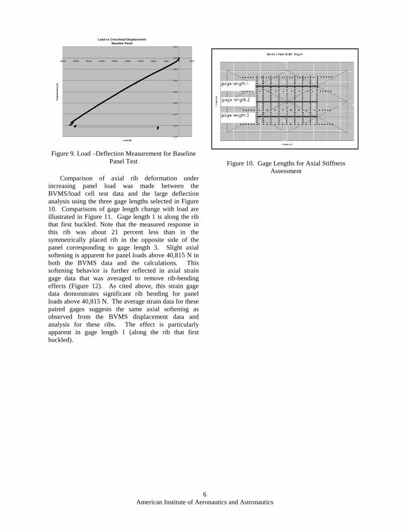
Post processing of the extensive displacement data obtained for the panel test demonstrated that the baseline panel, manufactured to the design radius of 76.2 cm, had increased in radius by about 20% at the time of test. Presumably this change occurred through stress relief and handling as the original cylinder was cut into panels and the ends of the panels were cast into thick epoxy edge bearings. Additionally, in the unloaded pretest state, there was a clear pattern of deformation, with the ribs tending to form ridges and the skin flattening the curvature of the panel slightly between ribs to induce a slight faceted appearance. The baseline panel in the Boeing compression test responded with roughly linear load-deflection resistance to failure at 188,160 N maximum load with some cracking and softening behavior above 177,801 N (Figure 9). This is in good agreement with the Collier post buckling analysis for this test reporting a maximum buckling load of 189,806 N.
6American Institute of Aeronautics and Astronautics
Figure 9. Load –Deflection Measurement for Baseline Panel Test
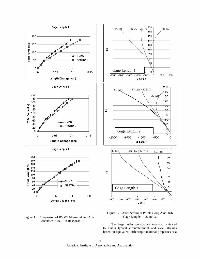
Comparison of axial rib deformation under
increasing panel load was made between the BVMS/load cell test data and the large deflection analysis using the three gage lengths selected in Figure 10. Comparisons of gage length change with load are illustrated in Figure 11. Gage length 1 is along the rib that first buckled. Note that the measured response in this rib was about 21 percent less than in the symmetrically placed rib in the opposite side of the panel corresponding to gage length 3. Slight axial softening is apparent for panel loads above 40,815 N in both the BVMS data and the calculations. This softening behavior is further reflected in axial strain gage data that was averaged to remove rib-bending effects (Figure 12). As cited above, this strain gage data demonstrates significant rib bending for panel loads above 40,815 N. The average strain data for these paired gages suggests the same axial softening as observed from the BVMS displacement data and analysis for these ribs. The effect is particularly apparent in gage length 1 (along the rib that first buckled).
Figure 10. Gage Lengths for Axial Stiffness Assessment
Load vs Crosshead Displacement Baseline Panel
-0.14
-0.12
-0.10
-0.08
-0.06
-0.04
-0.02
0.00
0.02
-45000 -40000 -35000 -30000 -25000 -20000 -15000 -10000 -5000 0 5000
Load (lb)
Dis
pla
cem
ent
(in
)
7American Institute of Aeronautics and Astronautics
Figure 11. Comparison of BVMS Measured and AFRL Calculated Axial Rib Response.
Figure 12. Axial Strains at Points along Axial Rib Gage Lengths 1, 2, and 3.
The large deflection analysis was also reviewed to assess typical circumferential and axial stresses based on equivalent orthotropic material properties at a
Gage Length 1
SG 5A(SG 5A + 5B ) / 2SG 5B
Gage Length 2
SG 12A (SG 12A + 12B) / 2
SG 12B
Gage Length 3
SG 14B (SG 14A + 14B) / 2 SG 14B
8American Institute of Aeronautics and Astronautics
maximum total load of 177,801 N. In this analysis stresses are reported for the middle shell location to omit bending effects in the various structural components and to more clearly show the distribution of primary forces in the panel (hoop and axial). The maximum principle stresses in the skin were oriented in the circumferential direction and did not exceed 62,052 kPa (tension). Tensile hoop stress bands were distributed axially in this calculation (Figure 13). The minimum principle stresses in the skin were oriented axially and averaged less than 13,789 kPa (compression) in regions away from the axial ribs (Figure 14). The minimum principle stress in the ribs was oriented along the direction of the ribs. Axial rib stresses typically exceeded diagonal rib stresses by factors of 2 to 4 and reached average values or roughly 275,790 kPa in the middle shell.
Figure 13. Maximum Principal Stress (Hoop Skin Stresses).
Figure 14. Minimum Principal Stress (Axial Skin Stresses)
Table 2 provides one estimate of the approximate
sharing of axial load within the panel. The table is based on rough average stresses described above. As anticipated from the design process for the panels, the axial ribs carry the major portion of axial loads.
Table 2. Computed Axial Load Distribution in Test Panel at 177,801 N Load (Prior to Rib
Buckling) Structural
Component Estimated
axial stress (kPa)
Total Load (N)
Percent Load
Axial Ribs 310,000 142100
80
Diagonal Ribs
69,000 13720 8
Skin 69,000 21560 12
Axial stress computed for all gage pairs on axial ribs averaged 206,500 kPa and ranged from 129,300 to 311,500 kPa. Axial stress computed for all gage pairs on helical ribs averaged 74,100 kPa and ranged from 12, 100 kPa (tension in one gage) to 160,100 kPa. From strain gage data, higher stresses were carried in the two outer axial ribs. The two ribs at quarter points of the circumference carried the lowest loads Observation, Analysis and Influence of First Axial Rib Failure:
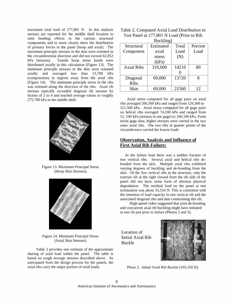
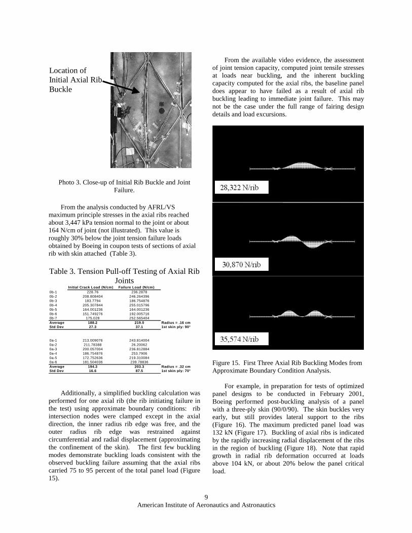
At the failure load there was a sudden fracture of two vertical ribs. Several axial and helical ribs de-bonded from the skin. Multiple axial ribs exhibited varying degrees of buckling and de-bonding from the skin. Of the five vertical ribs in the structure, only the exterior rib at the right viewed from the rib side of the panel did not have some form of obvious physical degradation. The residual load on the panel at test termination was about 35,554 N. This is consistent with the retention of load capacity in one vertical rib and the associated diagonal ribs and skin constraining this rib. High-speed video suggested that joint de-bonding and concurrent axial rib buckling might have initiated in one rib just prior to failure (Photos 2 and 3).
Photo 2. Initial Axial Rib Buckle (105,350 N).
Location of Initial Axial Rib Buckle
9American Institute of Aeronautics and Astronautics
Photo 3. Close-up of Initial Rib Buckle and Joint Failure.
From the analysis conducted by AFRL/VS
maximum principle stresses in the axial ribs reached about 3,447 kPa tension normal to the joint or about 164 N/cm of joint (not illustrated). This value is roughly 30% below the joint tension failure loads obtained by Boeing in coupon tests of sections of axial rib with skin attached (Table 3). Table 3. Tension Pull-off Testing of Axial Rib
Joints Initial Crack Load (N/cm) Failure Load (N/cm)
0b-1 228.76 236.28780b-2 208.808404 246.2643960b-3 183.7794 186.7548760b-4 205.307844 255.0157960b-5 164.001236 164.0012360b-6 151.749276 192.0057160b-7 175.028 252.565404Average 188.2 219.0 Radius = .16 cmStd Dev 27.3 37.1 1st skin ply: 90°
0a-1 213.009076 243.8140040a-2 211.78388 26.200620a-3 200.057004 236.8128840a-4 186.754876 253.79060a-5 172.752636 219.3100840a-6 181.504036 239.78836Average 194.3 203.3 Radius = .32 cmStd Dev 16.6 87.5 1st skin ply: 70°
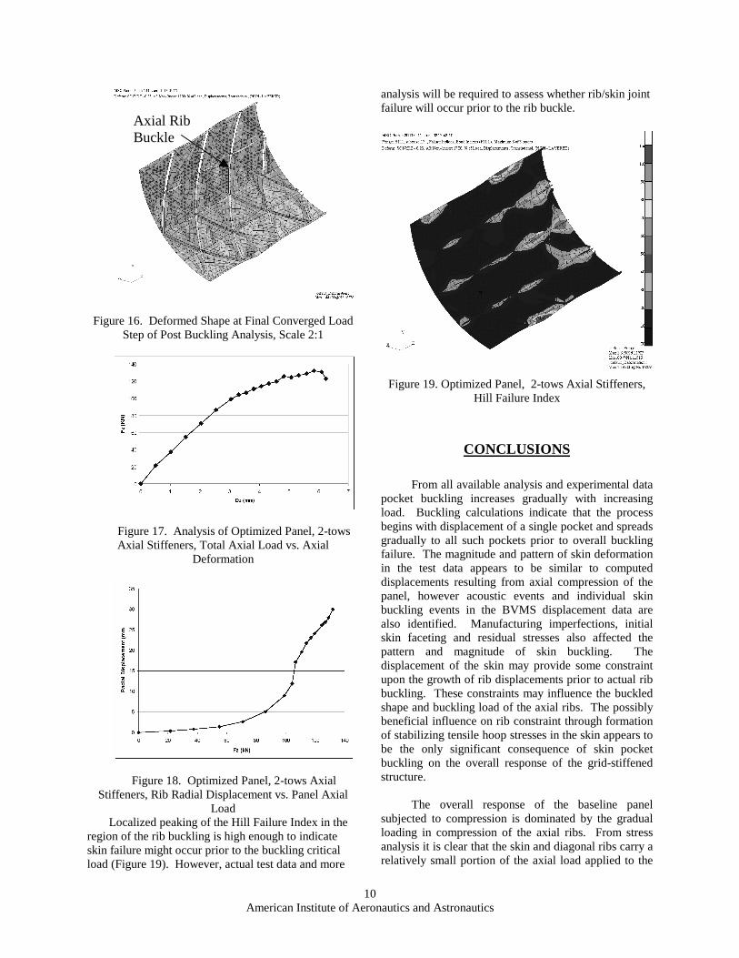
Additionally, a simplified buckling calculation was performed for one axial rib (the rib initiating failure in the test) using approximate boundary conditions: rib intersection nodes were clamped except in the axial direction, the inner radius rib edge was free, and the outer radius rib edge was restrained against circumferential and radial displacement (approximating the confinement of the skin). The first few buckling modes demonstrate buckling loads consistent with the observed buckling failure assuming that the axial ribs carried 75 to 95 percent of the total panel load (Figure 15).
From the available video evidence, the assessment
of joint tension capacity, computed joint tensile stresses at loads near buckling, and the inherent buckling capacity computed for the axial ribs, the baseline panel does appear to have failed as a result of axial rib buckling leading to immediate joint failure. This may not be the case under the full range of fairing design details and load excursions.
Figure 15. First Three Axial Rib Buckling Modes from Approximate Boundary Condition Analysis.
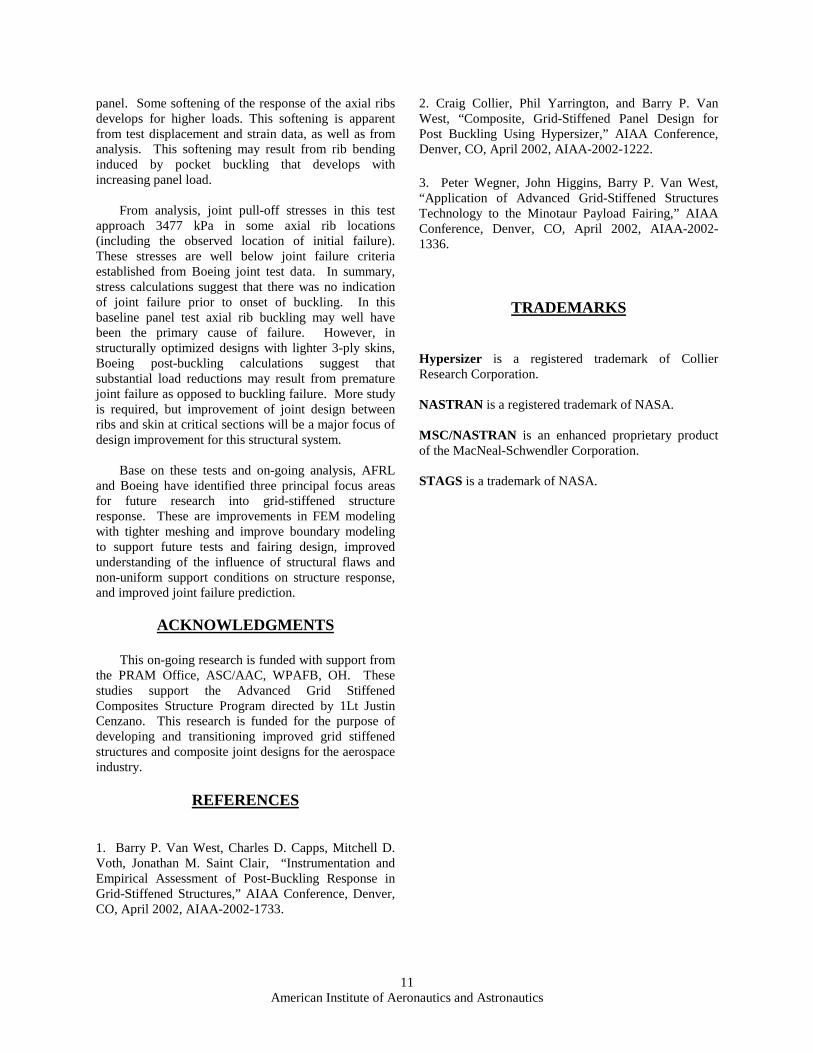
For example, in preparation for tests of optimized panel designs to be conducted in February 2001, Boeing performed post-buckling analysis of a panel with a three-ply skin (90/0/90). The skin buckles very early, but still provides lateral support to the ribs (Figure 16). The maximum predicted panel load was 132 kN (Figure 17). Buckling of axial ribs is indicated by the rapidly increasing radial displacement of the ribs in the region of buckling (Figure 18). Note that rapid growth in radial rib deformation occurred at loads above 104 kN, or about 20% below the panel critical load.
Location of Initial Axial Rib Buckle
10 American Institute of Aeronautics and Astronautics
Figure 16. Deformed Shape at Final Converged Load Step of Post Buckling Analysis, Scale 2:1
Figure 17. Analysis of Optimized Panel, 2-tows Axial Stiffeners, Total Axial Load vs. Axial
Deformation
Figure 18. Optimized Panel, 2-tows Axial Stiffeners, Rib Radial Displacement vs. Panel Axial
Load Localized peaking of the Hill Failure Index in the
region of the rib buckling is high enough to indicate skin failure might occur prior to the buckling critical load (Figure 19). However, actual test data and more
analysis will be required to assess whether rib/skin joint failure will occur prior to the rib buckle.
Figure 19. Optimized Panel, 2-tows Axial Stiffeners, Hill Failure Index
CONCLUSIONS
From all available analysis and experimental data pocket buckling increases gradually with increasing load. Buckling calculations indicate that the process begins with displacement of a single pocket and spreads gradually to all such pockets prior to overall buckling failure. The magnitude and pattern of skin deformation in the test data appears to be similar to computed displacements resulting from axial compression of the panel, however acoustic events and individual skin buckling events in the BVMS displacement data are also identified. Manufacturing imperfections, initial skin faceting and residual stresses also affected the pattern and magnitude of skin buckling. The displacement of the skin may provide some constraint upon the growth of rib displacements prior to actual rib buckling. These constraints may influence the buckled shape and buckling load of the axial ribs. The possibly beneficial influence on rib constraint through formation of stabilizing tensile hoop stresses in the skin appears to be the only significant consequence of skin pocket buckling on the overall response of the grid-stiffened structure.
The overall response of the baseline panel subjected to compression is dominated by the gradual loading in compression of the axial ribs. From stress analysis it is clear that the skin and diagonal ribs carry a relatively small portion of the axial load applied to the
Axial Rib Buckle
11 American Institute of Aeronautics and Astronautics
panel. Some softening of the response of the axial ribs develops for higher loads. This softening is apparent from test displacement and strain data, as well as from analysis. This softening may result from rib bending induced by pocket buckling that develops with increasing panel load.
From analysis, joint pull-off stresses in this test approach 3477 kPa in some axial rib locations (including the observed location of initial failure). These stresses are well below joint failure criteria established from Boeing joint test data. In summary, stress calculations suggest that there was no indication of joint failure prior to onset of buckling. In this baseline panel test axial rib buckling may well have been the primary cause of failure. However, in structurally optimized designs with lighter 3-ply skins, Boeing post-buckling calculations suggest that substantial load reductions may result from premature joint failure as opposed to buckling failure. More study is required, but improvement of joint design between ribs and skin at critical sections will be a major focus of design improvement for this structural system.
Base on these tests and on-going analysis, AFRL and Boeing have identified three principal focus areas for future research into grid-stiffened structure response. These are improvements in FEM modeling with tighter meshing and improve boundary modeling to support future tests and fairing design, improved understanding of the influence of structural flaws and non-uniform support conditions on structure response, and improved joint failure prediction.
ACKNOWLEDGMENTS
This on-going research is funded with support from the PRAM Office, ASC/AAC, WPAFB, OH. These studies support the Advanced Grid Stiffened Composites Structure Program directed by 1Lt Justin Cenzano. This research is funded for the purpose of developing and transitioning improved grid stiffened structures and composite joint designs for the aerospace industry.
REFERENCES
1. Barry P. Van West, Charles D. Capps, Mitchell D. Voth, Jonathan M. Saint Clair, “Instrumentation and Empirical Assessment of Post-Buckling Response in Grid-Stiffened Structures,” AIAA Conference, Denver, CO, April 2002, AIAA-2002-1733.
2. Craig Collier, Phil Yarrington, and Barry P. Van West, “Composite, Grid-Stiffened Panel Design for Post Buckling Using Hypersizer,” AIAA Conference, Denver, CO, April 2002, AIAA-2002-1222. 3. Peter Wegner, John Higgins, Barry P. Van West, “Application of Advanced Grid-Stiffened Structures Technology to the Minotaur Payload Fairing,” AIAA Conference, Denver, CO, April 2002, AIAA-2002-1336.
TRADEMARKS
Hypersizer is a registered trademark of Collier Research Corporation. NASTRAN is a registered trademark of NASA. MSC/NASTRAN is an enhanced proprietary product of the MacNeal-Schwendler Corporation. STAGS is a trademark of NASA.