Embed Size (px)
Citation preview
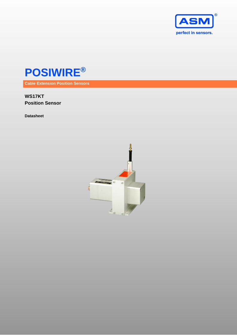
POSIWIRE® ®
Cable Extension Position Sensors
WS17KT
Position Sensor
Datasheet
POSIWIRE® WS17KT
DB-WS17KT-E-2017-04
1.1.0 | © ASM GmbH
2/20
www.asm-sensor.com
USA: www.asmsensors.com
Copyright
ASM Automation Sensorik Messtechnik GmbH Am Bleichbach 18-24 85452 Moosinning Germany
The information presented in this data sheet does not form part of any quotation or contract, is believed to be accurate and reliable and may be changed without notice. No liability will be accepted by ASM for any consequence of its use. Publication thereof does not convey nor imply any license under patent or industrial or intellectual property rights. Applications that are described herein for any of these products are for illustrative purpose only.
ASM makes no representation or warranty that such applications will be suitable for the specified use without further testing or modification.
POSIWIRE® WS17KT
DB-WS17KT-E-2017-04
1.1.0 | © ASM GmbH
3/20
www.asm-sensor.com
USA: www.asmsensors.com
Analog output, SSI output ............................................................................................................................... 4
Specifications ................................................................................................................................................. 4
Order code ..................................................................................................................................................... 6
Dimensions ....................................................................................................................................................... 7
Measurement range 1500 … 2000 … 2500 mm, analog output, SSI output................................................. 7
Measurement range 3000 ... 4000 mm, analog output, SSI output ............................................................... 8
Measurement range 5000 … 6250 mm, analog output, SSI output .............................................................. 9
Measurement range 10000 … 12500 … 15000 mm, analog output, SSI output......................................... 10
Output specifications ..................................................................................................................................... 11
Analog outputs ............................................................................................................................................. 11
Voltage divider R1K .................................................................................................................................. 11
Signal conditioner 10V and 10V5 ............................................................................................................. 12
Signal conditioner 420A ........................................................................................................................... 13
Signal conditioner 420T ............................................................................................................................ 14
Signal conditioner PMUI / PMUV ............................................................................................................. 15
Signal conditioner ADSI ........................................................................................................................... 17
Accessories ..................................................................................................................................................... 19
Connector cable M12, 8 pin ......................................................................................................................... 19
Plug-in connectors ....................................................................................................................................... 20
Plug-in connector M12, 8 pin (straight coupling) ...................................................................................... 20
POSIWIRE® WS17KT
DB-WS17KT-E-2017-04
1.1.0 | © ASM GmbH
4/20
www.asm-sensor.com
USA: www.asmsensors.com
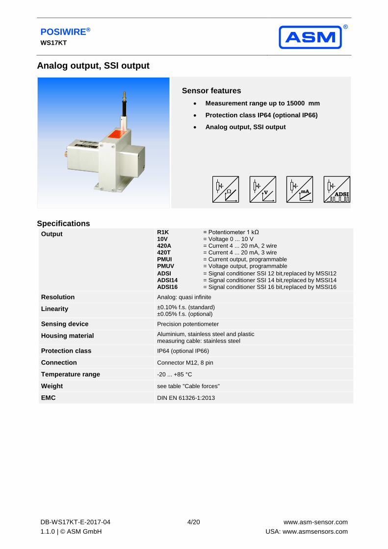
Analog output, SSI output
Sensor features
• Measurement range up to 15000 mm
• Protection class IP64 (optional IP66)
• Analog output, SSI output
Specifications
Output R1K = Potentiometer 1 kΩ 10V = Voltage 0 ... 10 V 420A = Current 4 ... 20 mA, 2 wire 420T = Current 4 ... 20 mA, 3 wire PMUI = Current output, programmable PMUV = Voltage output, programmable
ADSI = Signal conditioner SSI 12 bit,replaced by MSSI12 ADSI14 = Signal conditioner SSI 14 bit,replaced by MSSI14 ADSI16 = Signal conditioner SSI 16 bit,replaced by MSSI16
Resolution Analog: quasi infinite
Linearity ±0.10% f.s. (standard) ±0.05% f.s. (optional)
Sensing device Precision potentiometer
Housing material Aluminium, stainless steel and plastic measuring cable: stainless steel
Protection class IP64 (optional IP66)
Connection Connector M12, 8 pin
Temperature range -20 ... +85 °C
Weight see table "Cable forces"
EMC DIN EN 61326-1:2013
POSIWIRE® WS17KT
DB-WS17KT-E-2017-04
1.1.0 | © ASM GmbH
5/20
www.asm-sensor.com
USA: www.asmsensors.com
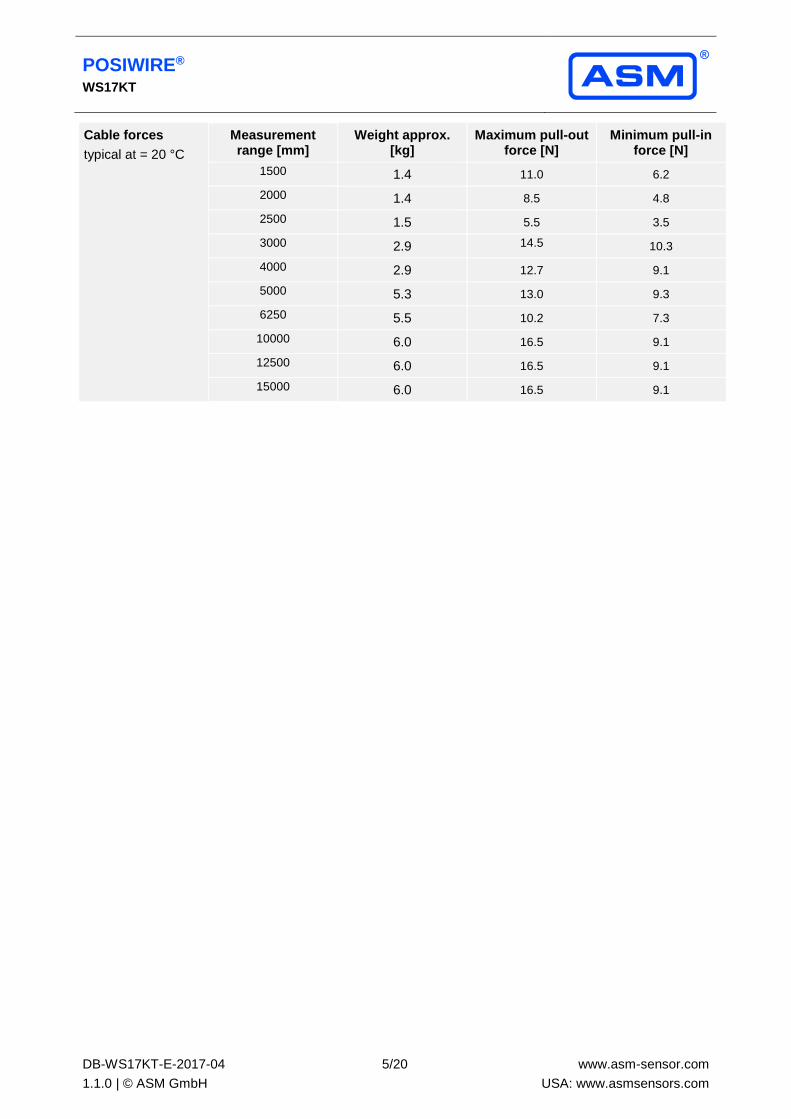
Cable forces
typical at = 20 °C
Measurement range [mm]
Weight approx. [kg]
Maximum pull-out force [N]
Minimum pull-in force [N]
1500 1.4 11.0 6.2
2000 1.4 8.5 4.8
2500 1.5 5.5 3.5
3000 2.9 14.5 10.3
4000 2.9 12.7 9.1
5000 5.3 13.0 9.3
6250 5.5 10.2 7.3
10000 6.0 16.5 9.1
12500 6.0 16.5 9.1
15000 6.0 16.5 9.1
POSIWIRE® WS17KT
DB-WS17KT-E-2017-04
1.1.0 | © ASM GmbH
6/20
www.asm-sensor.com
USA: www.asmsensors.com
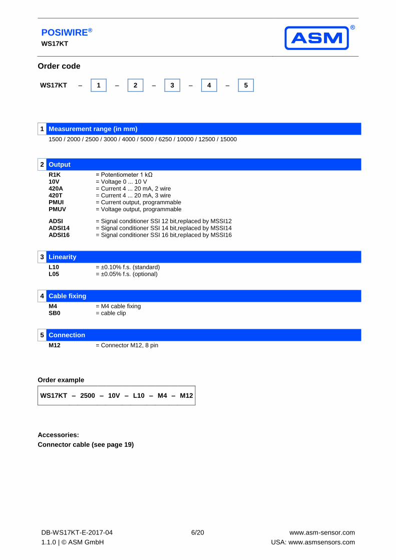
Order code
WS17KT – 1 – 2 – 3 – 4 – 5
1 Measurement range (in mm)
1500 / 2000 / 2500 / 3000 / 4000 / 5000 / 6250 / 10000 / 12500 / 15000
2 Output
R1K = Potentiometer 1 kΩ 10V = Voltage 0 ... 10 V 420A = Current 4 ... 20 mA, 2 wire 420T = Current 4 ... 20 mA, 3 wire PMUI = Current output, programmable PMUV = Voltage output, programmable
ADSI = Signal conditioner SSI 12 bit,replaced by MSSI12
ADSI14 = Signal conditioner SSI 14 bit,replaced by MSSI14 ADSI16 = Signal conditioner SSI 16 bit,replaced by MSSI16
3 Linearity
L10 = ±0.10% f.s. (standard) L05 = ±0.05% f.s. (optional)
4 Cable fixing
M4 = M4 cable fixing SB0 = cable clip
5 Connection
M12 = Connector M12, 8 pin
Order example
WS17KT – 2500 – 10V – L10 – M4 – M12
Accessories:
Connector cable (see page 19)
POSIWIRE® WS17KT
DB-WS17KT-E-2017-04
1.1.0 | © ASM GmbH
7/20
www.asm-sensor.com
USA: www.asmsensors.com
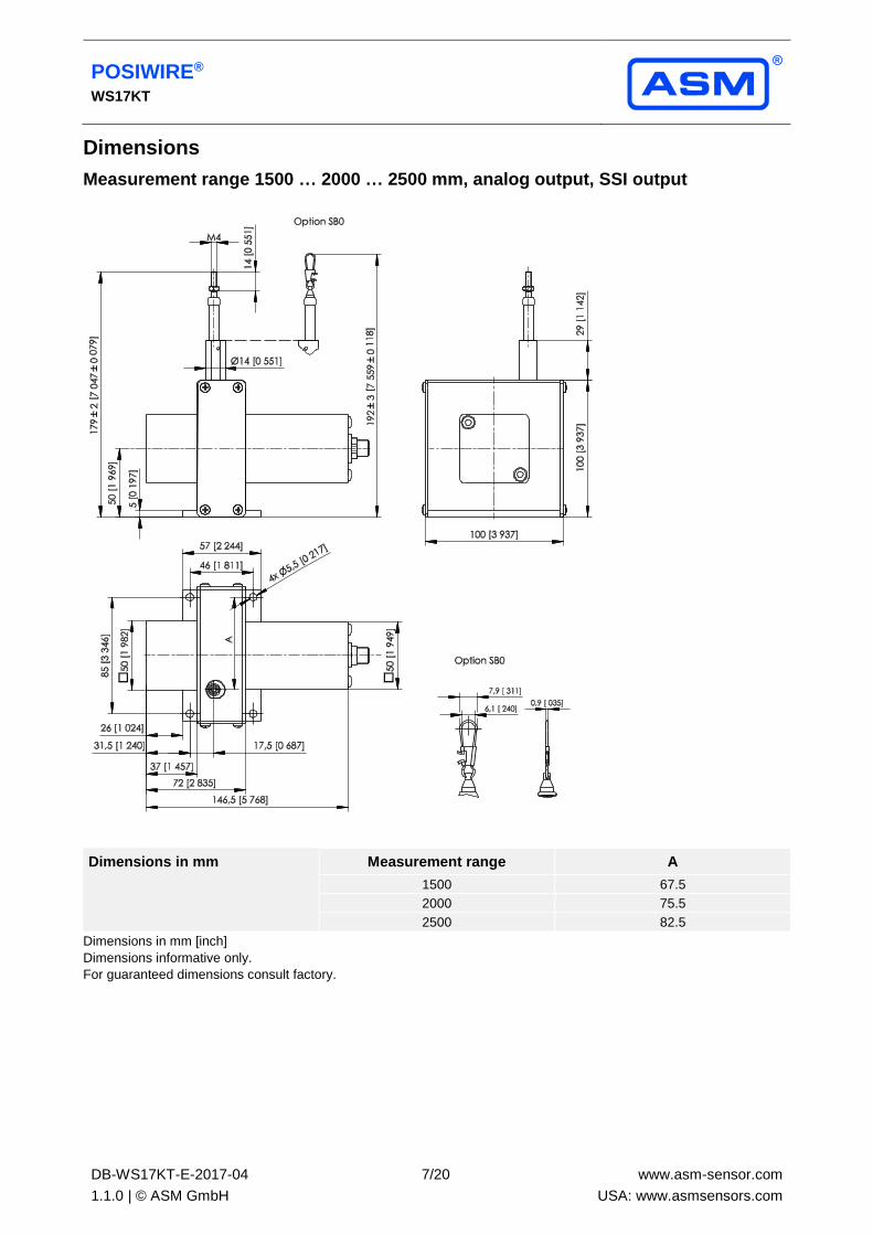
Dimensions
Measurement range 1500 … 2000 … 2500 mm, analog output, SSI output
Dimensions in mm Measurement range A
1500 67.5
2000 75.5
2500 82.5
Dimensions in mm [inch]
Dimensions informative only.
For guaranteed dimensions consult factory.
POSIWIRE® WS17KT
DB-WS17KT-E-2017-04
1.1.0 | © ASM GmbH
8/20
www.asm-sensor.com
USA: www.asmsensors.com
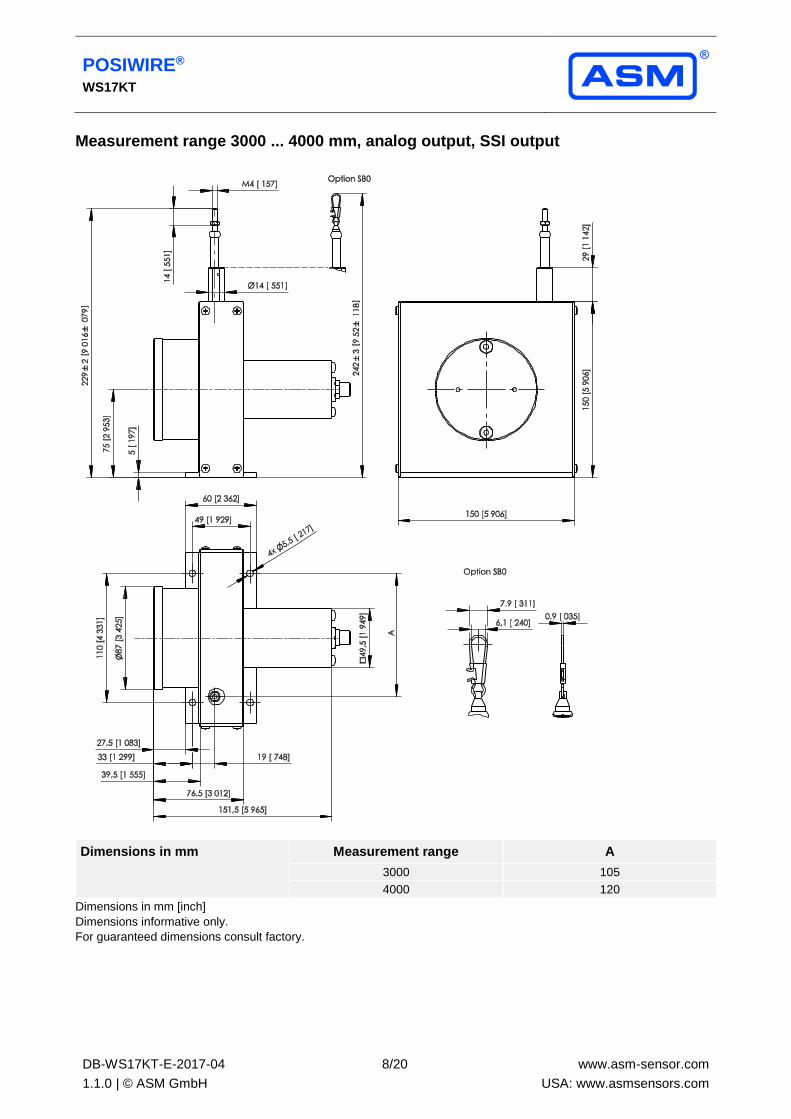
Measurement range 3000 ... 4000 mm, analog output, SSI output
Dimensions in mm Measurement range A
3000 105
4000 120
Dimensions in mm [inch]
Dimensions informative only.
For guaranteed dimensions consult factory.
POSIWIRE® WS17KT
DB-WS17KT-E-2017-04
1.1.0 | © ASM GmbH
9/20
www.asm-sensor.com
USA: www.asmsensors.com
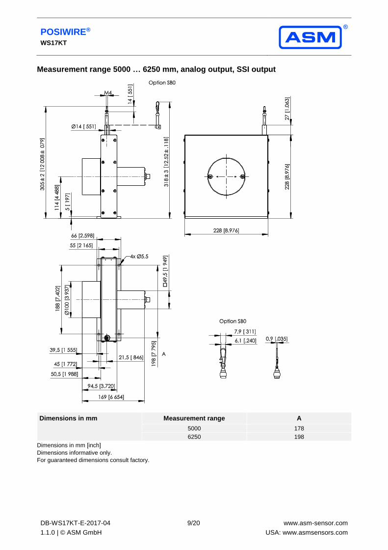
Measurement range 5000 … 6250 mm, analog output, SSI output
Dimensions in mm Measurement range A
5000 178
6250 198
Dimensions in mm [inch]
Dimensions informative only.
For guaranteed dimensions consult factory.
POSIWIRE® WS17KT
DB-WS17KT-E-2017-04
1.1.0 | © ASM GmbH
10/20
www.asm-sensor.com
USA: www.asmsensors.com
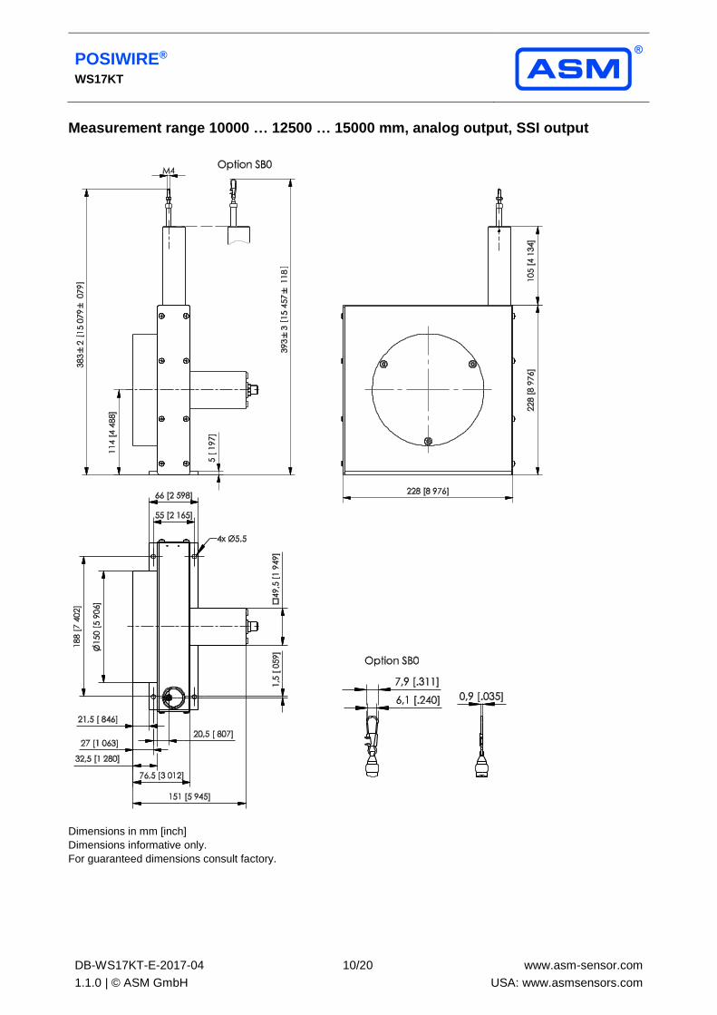
Measurement range 10000 … 12500 … 15000 mm, analog output, SSI output
Dimensions in mm [inch]
Dimensions informative only.
For guaranteed dimensions consult factory.
POSIWIRE® WS17KT
DB-WS17KT-E-2017-04
1.1.0 | © ASM GmbH
11/20
www.asm-sensor.com
USA: www.asmsensors.com
Output specifications
Analog outputs
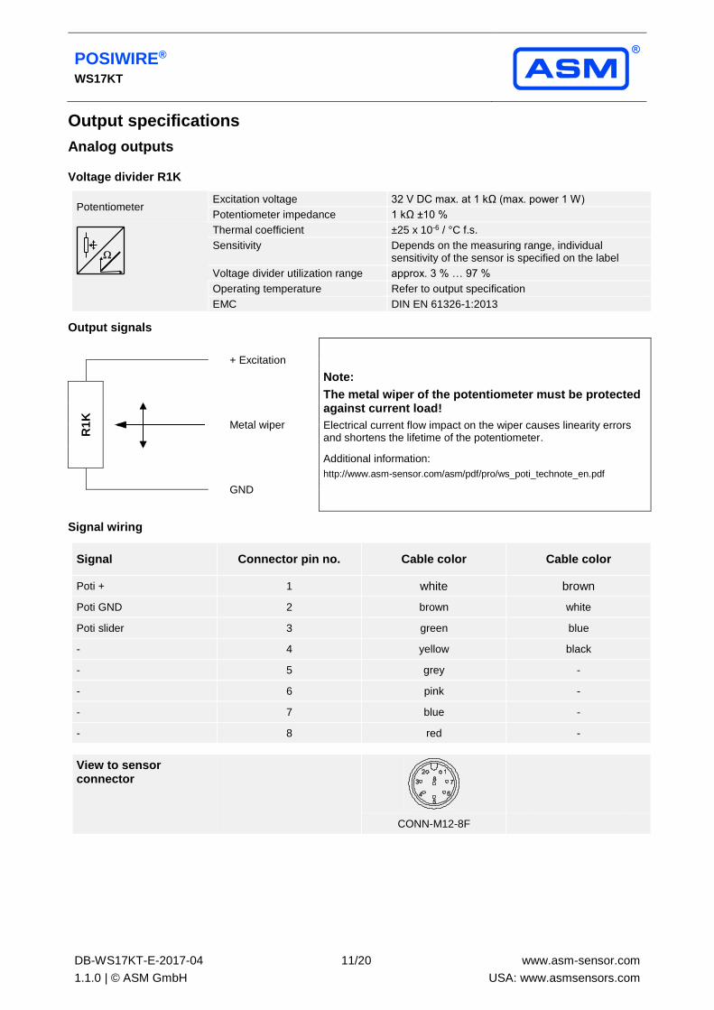
Voltage divider R1K
Potentiometer Excitation voltage 32 V DC max. at 1 kΩ (max. power 1 W)
Potentiometer impedance 1 kΩ ±10 %
Thermal coefficient ±25 x 10-6 / °C f.s.
Sensitivity Depends on the measuring range, individual sensitivity of the sensor is specified on the label
Voltage divider utilization range approx. 3 % … 97 %
Operating temperature Refer to output specification
EMC DIN EN 61326-1:2013
Output signals
+ Excitation
Note:
The metal wiper of the potentiometer must be protected against current load!
Electrical current flow impact on the wiper causes linearity errors and shortens the lifetime of the potentiometer.
Additional information:
http://www.asm-sensor.com/asm/pdf/pro/ws_poti_technote_en.pdf
R1K
Metal wiper
GND
Signal wiring
Signal Connector pin no. Cable color Cable color
Poti + 1 white brown
Poti GND 2 brown white
Poti slider 3 green blue
- 4 yellow black
- 5 grey -
- 6 pink -
- 7 blue -
- 8 red -
View to sensor connector
CONN-M12-8F
POSIWIRE® WS17KT
DB-WS17KT-E-2017-04
1.1.0 | © ASM GmbH
12/20
www.asm-sensor.com
USA: www.asmsensors.com
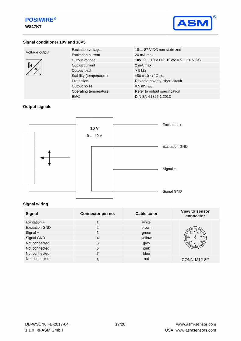
Signal conditioner 10V and 10V5
Voltage output Excitation voltage 18 ... 27 V DC non stabilized
Excitation current 20 mA max.
Output voltage 10V: 0 ... 10 V DC; 10V5: 0.5 ... 10 V DC
Output current 2 mA max.
Output load > 5 kΩ
Stability (temperature) ±50 x 10-6 / °C f.s.
Protection Reverse polarity, short circuit
Output noise 0.5 mVRMS
Operating temperature Refer to output specification
EMC DIN EN 61326-1:2013
Output signals
Excitation +
10 V
0 … 10 V
Excitation GND
Signal +
Signal GND
Signal wiring
Signal Connector pin no. Cable color View to sensor
connector
Excitation + 1 white
Excitation GND 2 brown
Signal + 3 green
Signal GND 4 yellow
Not connected 5 grey
Not connected 6 pink
Not connected 7 blue
Not connected 8 red CONN-M12-8F
POSIWIRE® WS17KT
DB-WS17KT-E-2017-04
1.1.0 | © ASM GmbH
13/20
www.asm-sensor.com
USA: www.asmsensors.com
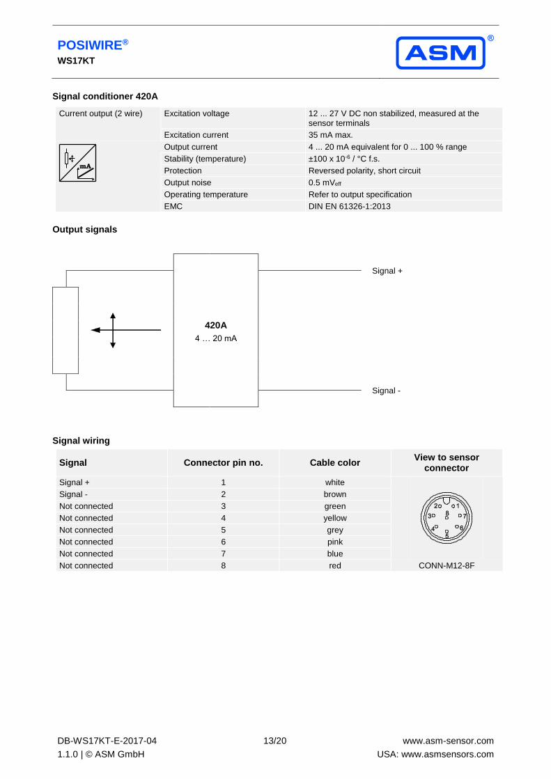
Signal conditioner 420A
Current output (2 wire) Excitation voltage 12 ... 27 V DC non stabilized, measured at the sensor terminals
Excitation current 35 mA max.
Output current 4 ... 20 mA equivalent for 0 ... 100 % range
Stability (temperature) ±100 x 10-6 / °C f.s.
Protection Reversed polarity, short circuit
Output noise 0.5 mVeff
Operating temperature Refer to output specification
EMC DIN EN 61326-1:2013
Output signals
420A
4 … 20 mA
Signal +
Signal -
Signal wiring
Signal Connector pin no. Cable color View to sensor
connector
Signal + 1 white
Signal - 2 brown
Not connected 3 green
Not connected 4 yellow
Not connected 5 grey
Not connected 6 pink
Not connected 7 blue
Not connected 8 red CONN-M12-8F
POSIWIRE® WS17KT
DB-WS17KT-E-2017-04
1.1.0 | © ASM GmbH
14/20
www.asm-sensor.com
USA: www.asmsensors.com
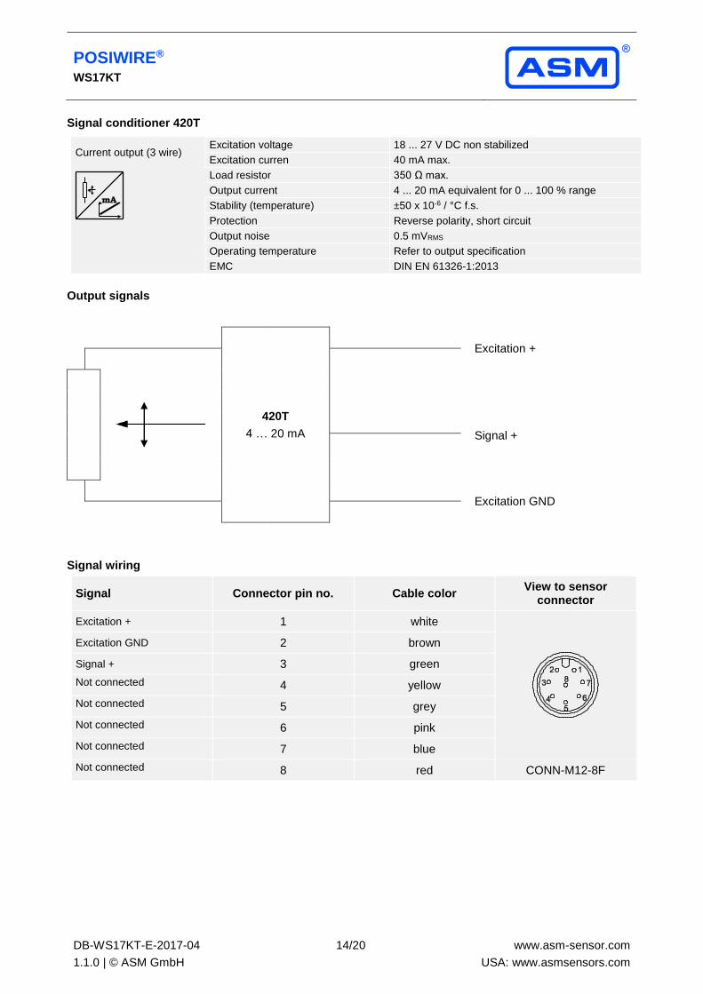
Signal conditioner 420T
Current output (3 wire) Excitation voltage 18 ... 27 V DC non stabilized
Excitation curren 40 mA max.
Load resistor 350 Ω max.
Output current 4 ... 20 mA equivalent for 0 ... 100 % range
Stability (temperature) ±50 x 10-6 / °C f.s.
Protection Reverse polarity, short circuit
Output noise 0.5 mVRMS
Operating temperature Refer to output specification
EMC DIN EN 61326-1:2013
Output signals
420T
4 … 20 mA
Excitation +
Signal +
Excitation GND
Signal wiring
Signal Connector pin no. Cable color View to sensor
connector
Excitation + 1 white
Excitation GND 2 brown
Signal + 3 green
Not connected 4 yellow
Not connected 5 grey
Not connected 6 pink
Not connected 7 blue
Not connected 8 red CONN-M12-8F
POSIWIRE® WS17KT
DB-WS17KT-E-2017-04
1.1.0 | © ASM GmbH
15/20
www.asm-sensor.com
USA: www.asmsensors.com
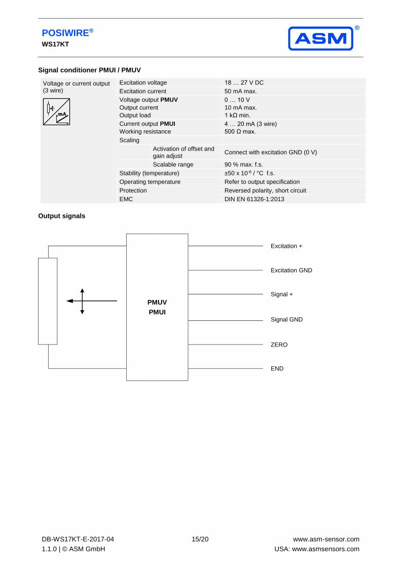
Signal conditioner PMUI / PMUV
Voltage or current output (3 wire)
Excitation voltage 18 … 27 V DC
Excitation current 50 mA max.
Voltage output PMUV
Output current
Output load
0 … 10 V
10 mA max.
1 kΩ min.
Current output PMUI
Working resistance
4 … 20 mA (3 wire)
500 Ω max.
Scaling
Activation of offset and gain adjust
Connect with excitation GND (0 V)
Scalable range 90 % max. f.s.
Stability (temperature) ±50 x 10-6 / °C f.s.
Operating temperature Refer to output specification
Protection Reversed polarity, short circuit
EMC DIN EN 61326-1:2013
Output signals
PMUV
PMUI
Excitation +
Excitation GND
Signal +
Signal GND
ZERO
END
POSIWIRE® WS17KT
DB-WS17KT-E-2017-04
1.1.0 | © ASM GmbH
16/20
www.asm-sensor.com
USA: www.asmsensors.com
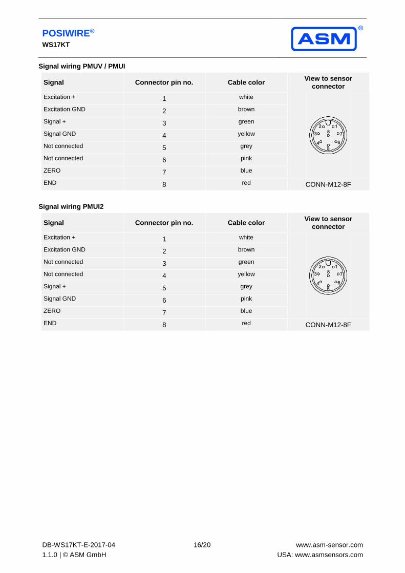
Signal wiring PMUV / PMUI
Signal Connector pin no. Cable color View to sensor
connector
Excitation + 1 white
Excitation GND 2 brown
Signal + 3 green
Signal GND 4 yellow
Not connected 5 grey
Not connected 6 pink
ZERO 7 blue
END 8 red CONN-M12-8F
Signal wiring PMUI2
Signal Connector pin no. Cable color View to sensor
connector
Excitation + 1 white
Excitation GND 2 brown
Not connected 3 green
Not connected 4 yellow
Signal + 5 grey
Signal GND 6 pink
ZERO 7 blue
END 8 red CONN-M12-8F
POSIWIRE® WS17KT
DB-WS17KT-E-2017-04
1.1.0 | © ASM GmbH
17/20
www.asm-sensor.com
USA: www.asmsensors.com
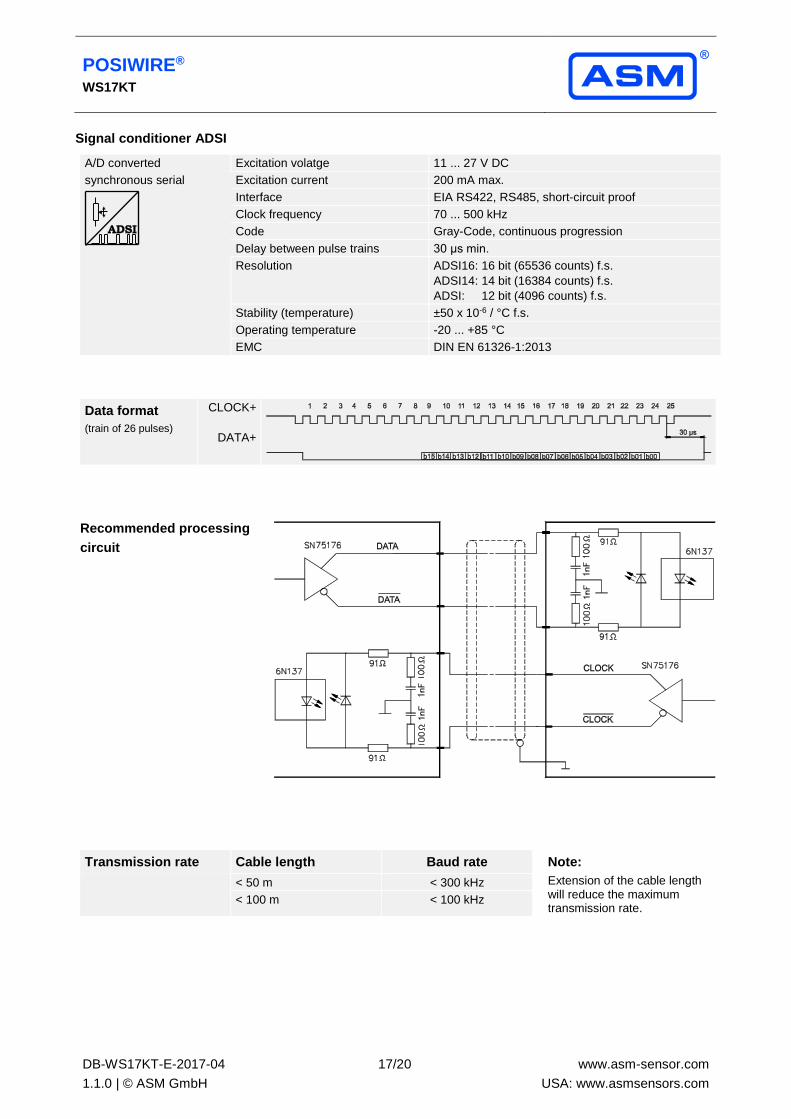
Signal conditioner ADSI
A/D converted Excitation volatge 11 ... 27 V DC
synchronous serial
Excitation current 200 mA max.
Interface EIA RS422, RS485, short-circuit proof
Clock frequency 70 ... 500 kHz
Code Gray-Code, continuous progression
Delay between pulse trains 30 μs min.
Resolution ADSI16: 16 bit (65536 counts) f.s.
ADSI14: 14 bit (16384 counts) f.s.
ADSI: 12 bit (4096 counts) f.s.
Stability (temperature) ±50 x 10-6 / °C f.s.
Operating temperature -20 ... +85 °C
EMC DIN EN 61326-1:2013
Data format
(train of 26 pulses)
CLOCK+
DATA+
Recommended processing
circuit
Transmission rate Cable length Baud rate Note:
Extension of the cable length will reduce the maximum transmission rate.
< 50 m < 300 kHz
< 100 m < 100 kHz
POSIWIRE® WS17KT
DB-WS17KT-E-2017-04
1.1.0 | © ASM GmbH
18/20
www.asm-sensor.com
USA: www.asmsensors.com
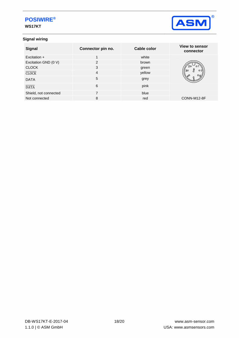
Signal wiring
Signal Connector pin no. Cable color View to sensor
connector
Excitation + 1 white
Excitation GND (0 V) 2 brown
CLOCK 3 green
CLOCK 4 yellow
DATA 5 grey
DATA 6 pink
Shield, not connected 7 blue
Not connected 8 red CONN-M12-8F
POSIWIRE® WS17KT
DB-WS17KT-E-2017-04
1.1.0 | © ASM GmbH
19/20
www.asm-sensor.com
USA: www.asmsensors.com
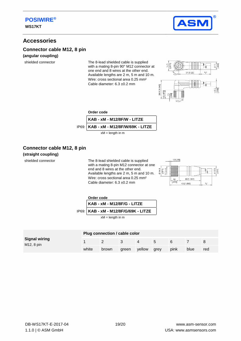
Accessories
Connector cable M12, 8 pin
(angular coupling)
shielded connector The 8-lead shielded cable is supplied with a mating 8-pin 90° M12 connector at one end and 8 wires at the other end. Available lengths are 2 m, 5 m and 10 m.
Wire: cross sectional area 0.25 mm²
Cable diameter: 6.3 ±0.2 mm
Order code
KAB - xM - M12/8F/W - LITZE
IP69: KAB - xM - M12/8F/W/69K - LITZE
xM = length in m
Connector cable M12, 8 pin
(straight coupling)
shielded connector The 8-lead shielded cable is supplied with a mating 8-pin M12 connector at one end and 8 wires at the other end. Available lengths are 2 m, 5 m and 10 m.
Wire: cross sectional area 0.25 mm²
Cable diameter: 6.3 ±0.2 mm
Order code
KAB - xM - M12/8F/G - LITZE
IP69: KAB - xM - M12/8F/G/69K - LITZE
xM = length in m
Signal wiring
M12, 8 pin
Plug connection / cable color
1 2 3 4 5 6 7 8
white brown green yellow grey pink blue red
POSIWIRE® WS17KT
DB-WS17KT-E-2017-04
1.1.0 | © ASM GmbH
20/20
www.asm-sensor.com
USA: www.asmsensors.com
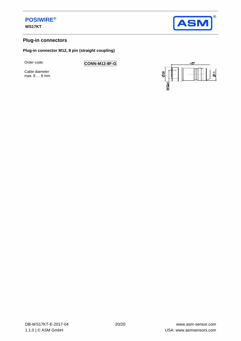
Plug-in connectors
Plug-in connector M12, 8 pin (straight coupling)
Order code:
Cable diameter max. 6 … 8 mm
CONN-M12-8F-G