Embed Size (px)
DESCRIPTION
avaya
Citation preview
CRK; Reviewed:
SPOC 8/18/2009
Solution & Interoperability Test Lab Application Notes
©2009 Avaya Inc. All Rights Reserved.
1 of 36
Positron-ACM-AES
Avaya Solution & Interoperability Test Lab
Application Notes for Positron VIPER and Avaya AuraTM
Communication Manager and Avaya AuraTM
Application
Enablement Services – Issue 1.0
Abstract
These Application Notes describe the configuration steps required for the Positron Voice over
IP for Emergency Response (VIPER) system to successfully interoperate with Avaya AuraTM
Communication Manager using Avaya AuraTM
Application Enablement Services.
Positron VIPER is an Enhanced 9-1-1 ANI/ALI controller that provides VoIP as a telephony
layer. Positron VIPER integrates with Avaya S8300 Server with Avaya G450 Media Gateway
to provide a streamlined backroom within the Public Safety Answering Point (PSAP).
Information in these Application Notes has been obtained through DevConnect compliance
testing and additional technical discussions. Testing was conducted via the DevConnect
Program at the Avaya Solution and Interoperability Test Lab.

CRK; Reviewed:
SPOC 8/18/2009
Solution & Interoperability Test Lab Application Notes
©2009 Avaya Inc. All Rights Reserved.
2 of 36
Positron-ACM-AES
1. Introduction These Application Notes describe the procedures for configuring Positron VIPER which was
compliance tested with Avaya AuraTM
Communication Manager and Avaya AuraTM
Application
Enablement Services.
The intent of this document is to describe Avaya integration with Positron VIPER using analog
or T1 interface to manage 911 calls delivered to a PSAP using CAMA analog trunk or T1 from
Central Office. During the test, ANI was simulated using the Positron CAMA Interface Module
(CIM).
Positron VIPER is an Enhanced 9-1-1 ANI/ALI controller that provides VoIP as a telephony
layer. Positron VIPER integrates with Avaya PBX to provide a streamlined backroom within
PSAP. Positron VIPER is an IP based emergency response system that:
Receive 9-1-1 emergency and administrative calls
Automatically looks up ALI based on ANI and other information
Presents the call to a call taker at Positron Power911 position
Enables call takers to transfer call and data to different agencies (police, fire, Sheriff’s
office…)
The Positron backroom POTS servers function as an active/standby, with the standby ready to
take over from the active upon failure. The redundant VIPER POTS servers communicate with
each Application Enablement Services (AES) server on CTI link. Telephony Services
Application Programming Interface (TSAPI) is used to automatically retrieve relevant
provisioning information from Avaya Communication Manager and monitor call flow.
The Positron Power911 Intelligent Workstation (IWS) enables the 911 call answering agent to
easily manage and handle 9-1-1 calls. The Power911 provides visualized incoming call alerts,
dynamic call status indicators, intelligent call prompting, call recording, one-button transfer for
voice and data, TTY, SMS, and much more. Each Power911 IWS has a Device, Media and Call
Control (DMCC) API connection to Avaya AES. The DMCC API services are utilized by
Power911 to support login, answer, transfer calls, as well as first-party call controls of buttons,
lamps, or display on the telephony set.
The Positron Management Gateway (PMG) is a browser-based application used to configure and
maintain Positron VIPER. During configuration, trunks, lines, telephony, and position
information is entered into a database. This data is then transferred to each system components
and IWS positions through system synchronization services. The PMG implements Avaya
System Management Services (SMS) client to retrieve and manage objects in Avaya
Communication Manager for the VIPER system.
The following Avaya services and APIs are used to implement specific functions for VIPER:
Telephony Server Application Programming Interface (TSAPI) is a CTI standard
consists of a number of 3rd-party call control and call monitor commands. The VIPER
CRK; Reviewed:
SPOC 8/18/2009
Solution & Interoperability Test Lab Application Notes
©2009 Avaya Inc. All Rights Reserved.
3 of 36
Positron-ACM-AES
system has a service running on the POTS server that implements TSAPI to monitor call
status.
Avaya Device, Media and Call Control (DMCC) SDK provides access to
Communication Manager’s device, media, and basic call control capabilities. Positron
Power911 IWS uses this interface to implement call control features.
Avaya System Management Services (SMS) is a web service runs on Avaya AES
server. It exposes management and provisioning features of Communication Manager.
This service enables SMS client to display, list, add, change and remove specific
managed objects in Communication Manager. Positron Management Gateway (PMG)
implements SMS client to access the administration objects.
These Application Notes assume that Avaya AuraTM
Communication Manager and Avaya
AuraTM
Application Enablement Services are already installed and basic configuration steps have
been performed. Only steps relevant to this compliance test will be described in this document.
For further details on configuration steps not covered in this document, consult [5].
1.1. Interoperability Compliance Testing
The interoperability compliance test included features and serviceability. The focus of the
interoperability compliance testing was primarily on verifying call establishment, ANI, and ALI
information from the Positron Power911 Intelligent Workstation. During the test, operations
such as inbound calls, outbound calls, hold, transfer, conference were performed.
1.2. Support
Technical support on Positron VIPER can be reached through the following:
Tel: 800-361-2596
Email: [email protected]
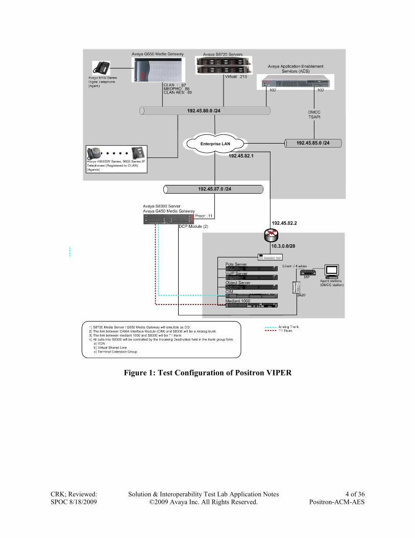
2. Reference Configuration Figure 1 illustrates a sample configuration consisting of an Avaya S8300 Server, an Avaya
G450 Media Gateway, an Avaya Application Enablement Services (AES) server, and the
Positron VIPER system. The solution described herein is also extensible to other Avaya Media
Servers and Media Gateways. Avaya S8720 Servers with an Avaya G650 Media Gateway were
included in the test to simulate CO. For completeness, Avaya 9600 Series H.323 IP Telephones,
Avaya 4600 Series H.323 IP Telephones, and Avaya 6400 Series Digital Telephones are
included in Figure 1 to demonstrate calls between CO and the Positron Power911 Intelligent
Workstation.
CRK; Reviewed:
SPOC 8/18/2009
Solution & Interoperability Test Lab Application Notes
©2009 Avaya Inc. All Rights Reserved.
4 of 36
Positron-ACM-AES
Figure 1: Test Configuration of Positron VIPER
CRK; Reviewed:
SPOC 8/18/2009
Solution & Interoperability Test Lab Application Notes
©2009 Avaya Inc. All Rights Reserved.
5 of 36
Positron-ACM-AES
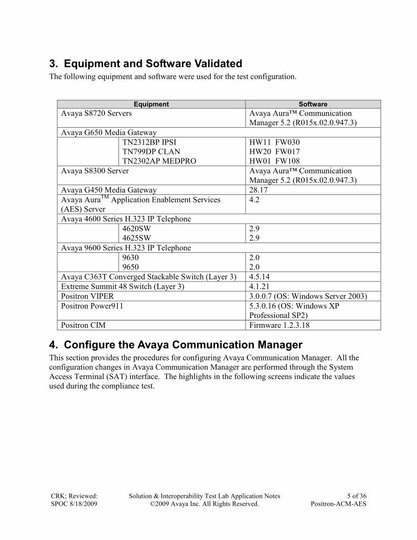
3. Equipment and Software Validated The following equipment and software were used for the test configuration.
Equipment Software
Avaya S8720 Servers Avaya Aura™ Communication
Manager 5.2 (R015x.02.0.947.3)
Avaya G650 Media Gateway
TN2312BP IPSI
TN799DP CLAN
TN2302AP MEDPRO
HW11 FW030
HW20 FW017
HW01 FW108
Avaya S8300 Server Avaya Aura™ Communication
Manager 5.2 (R015x.02.0.947.3)
Avaya G450 Media Gateway 28.17
Avaya AuraTM
Application Enablement Services
(AES) Server
4.2
Avaya 4600 Series H.323 IP Telephone
4620SW
4625SW
2.9
2.9
Avaya 9600 Series H.323 IP Telephone
9630
9650
2.0
2.0
Avaya C363T Converged Stackable Switch (Layer 3) 4.5.14
Extreme Summit 48 Switch (Layer 3) 4.1.21
Positron VIPER 3.0.0.7 (OS: Windows Server 2003)
Positron Power911 5.3.0.16 (OS: Windows XP
Professional SP2)
Positron CIM Firmware 1.2.3.18
4. Configure the Avaya Communication Manager This section provides the procedures for configuring Avaya Communication Manager. All the
configuration changes in Avaya Communication Manager are performed through the System
Access Terminal (SAT) interface. The highlights in the following screens indicate the values
used during the compliance test.
CRK; Reviewed:
SPOC 8/18/2009
Solution & Interoperability Test Lab Application Notes
©2009 Avaya Inc. All Rights Reserved.
6 of 36
Positron-ACM-AES
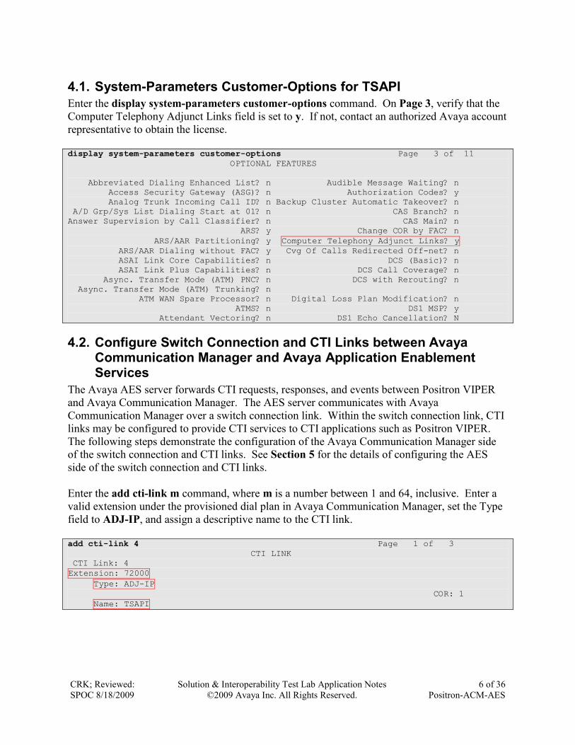
4.1. System-Parameters Customer-Options for TSAPI
Enter the display system-parameters customer-options command. On Page 3, verify that the
Computer Telephony Adjunct Links field is set to y. If not, contact an authorized Avaya account
representative to obtain the license.
display system-parameters customer-options Page 3 of 11
OPTIONAL FEATURES
Abbreviated Dialing Enhanced List? n Audible Message Waiting? n
Access Security Gateway (ASG)? n Authorization Codes? y
Analog Trunk Incoming Call ID? n Backup Cluster Automatic Takeover? n
A/D Grp/Sys List Dialing Start at 01? n CAS Branch? n
Answer Supervision by Call Classifier? n CAS Main? n
ARS? y Change COR by FAC? n
ARS/AAR Partitioning? y Computer Telephony Adjunct Links? y
ARS/AAR Dialing without FAC? y Cvg Of Calls Redirected Off-net? n
ASAI Link Core Capabilities? n DCS (Basic)? n
ASAI Link Plus Capabilities? n DCS Call Coverage? n
Async. Transfer Mode (ATM) PNC? n DCS with Rerouting? n
Async. Transfer Mode (ATM) Trunking? n
ATM WAN Spare Processor? n Digital Loss Plan Modification? n
ATMS? n DS1 MSP? y
Attendant Vectoring? n DS1 Echo Cancellation? N
4.2. Configure Switch Connection and CTI Links between Avaya Communication Manager and Avaya Application Enablement Services
The Avaya AES server forwards CTI requests, responses, and events between Positron VIPER
and Avaya Communication Manager. The AES server communicates with Avaya
Communication Manager over a switch connection link. Within the switch connection link, CTI
links may be configured to provide CTI services to CTI applications such as Positron VIPER.
The following steps demonstrate the configuration of the Avaya Communication Manager side
of the switch connection and CTI links. See Section 5 for the details of configuring the AES
side of the switch connection and CTI links.
Enter the add cti-link m command, where m is a number between 1 and 64, inclusive. Enter a
valid extension under the provisioned dial plan in Avaya Communication Manager, set the Type
field to ADJ-IP, and assign a descriptive name to the CTI link.
add cti-link 4 Page 1 of 3
CTI LINK
CTI Link: 4
Extension: 72000
Type: ADJ-IP
COR: 1
Name: TSAPI
CRK; Reviewed:
SPOC 8/18/2009
Solution & Interoperability Test Lab Application Notes
©2009 Avaya Inc. All Rights Reserved.
7 of 36
Positron-ACM-AES
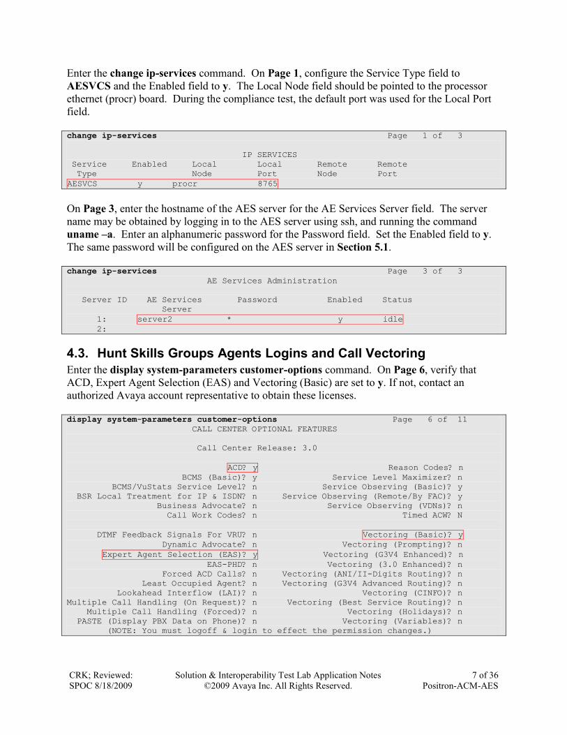
Enter the change ip-services command. On Page 1, configure the Service Type field to
AESVCS and the Enabled field to y. The Local Node field should be pointed to the processor
ethernet (procr) board. During the compliance test, the default port was used for the Local Port
field.
change ip-services Page 1 of 3
IP SERVICES
Service Enabled Local Local Remote Remote
Type Node Port Node Port
AESVCS y procr 8765
On Page 3, enter the hostname of the AES server for the AE Services Server field. The server
name may be obtained by logging in to the AES server using ssh, and running the command
uname –a. Enter an alphanumeric password for the Password field. Set the Enabled field to y.
The same password will be configured on the AES server in Section 5.1.
change ip-services Page 3 of 3
AE Services Administration
Server ID AE Services Password Enabled Status
Server
1: server2 * y idle
2:
4.3. Hunt Skills Groups Agents Logins and Call Vectoring
Enter the display system-parameters customer-options command. On Page 6, verify that
ACD, Expert Agent Selection (EAS) and Vectoring (Basic) are set to y. If not, contact an
authorized Avaya account representative to obtain these licenses.
display system-parameters customer-options Page 6 of 11
CALL CENTER OPTIONAL FEATURES
Call Center Release: 3.0
ACD? y Reason Codes? n
BCMS (Basic)? y Service Level Maximizer? n
BCMS/VuStats Service Level? n Service Observing (Basic)? y
BSR Local Treatment for IP & ISDN? n Service Observing (Remote/By FAC)? y
Business Advocate? n Service Observing (VDNs)? n
Call Work Codes? n Timed ACW? N
DTMF Feedback Signals For VRU? n Vectoring (Basic)? y
Dynamic Advocate? n Vectoring (Prompting)? n
Expert Agent Selection (EAS)? y Vectoring (G3V4 Enhanced)? n
EAS-PHD? n Vectoring (3.0 Enhanced)? n
Forced ACD Calls? n Vectoring (ANI/II-Digits Routing)? n
Least Occupied Agent? n Vectoring (G3V4 Advanced Routing)? n
Lookahead Interflow (LAI)? n Vectoring (CINFO)? n
Multiple Call Handling (On Request)? n Vectoring (Best Service Routing)? n
Multiple Call Handling (Forced)? n Vectoring (Holidays)? n
PASTE (Display PBX Data on Phone)? n Vectoring (Variables)? n
(NOTE: You must logoff & login to effect the permission changes.)
CRK; Reviewed:
SPOC 8/18/2009
Solution & Interoperability Test Lab Application Notes
©2009 Avaya Inc. All Rights Reserved.
8 of 36
Positron-ACM-AES
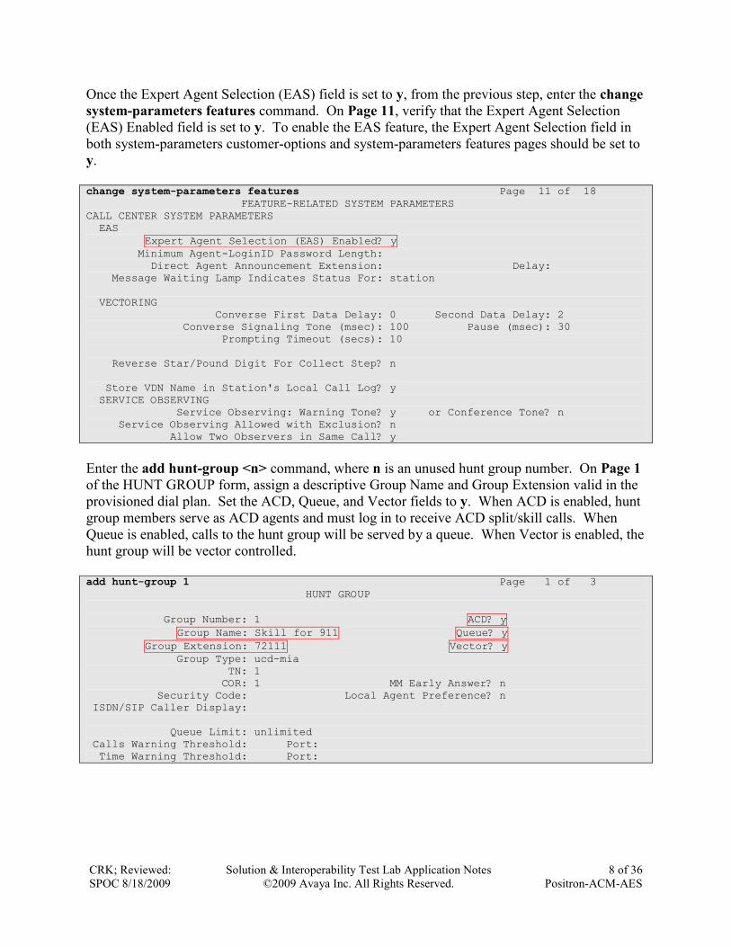
Once the Expert Agent Selection (EAS) field is set to y, from the previous step, enter the change
system-parameters features command. On Page 11, verify that the Expert Agent Selection
(EAS) Enabled field is set to y. To enable the EAS feature, the Expert Agent Selection field in
both system-parameters customer-options and system-parameters features pages should be set to
y.
change system-parameters features Page 11 of 18
FEATURE-RELATED SYSTEM PARAMETERS
CALL CENTER SYSTEM PARAMETERS
EAS
Expert Agent Selection (EAS) Enabled? y
Minimum Agent-LoginID Password Length:
Direct Agent Announcement Extension: Delay:
Message Waiting Lamp Indicates Status For: station
VECTORING
Converse First Data Delay: 0 Second Data Delay: 2
Converse Signaling Tone (msec): 100 Pause (msec): 30
Prompting Timeout (secs): 10
Reverse Star/Pound Digit For Collect Step? n
Store VDN Name in Station's Local Call Log? y
SERVICE OBSERVING
Service Observing: Warning Tone? y or Conference Tone? n
Service Observing Allowed with Exclusion? n
Allow Two Observers in Same Call? y
Enter the add hunt-group <n> command, where n is an unused hunt group number. On Page 1
of the HUNT GROUP form, assign a descriptive Group Name and Group Extension valid in the
provisioned dial plan. Set the ACD, Queue, and Vector fields to y. When ACD is enabled, hunt
group members serve as ACD agents and must log in to receive ACD split/skill calls. When
Queue is enabled, calls to the hunt group will be served by a queue. When Vector is enabled, the
hunt group will be vector controlled.
add hunt-group 1 Page 1 of 3
HUNT GROUP
Group Number: 1 ACD? y
Group Name: Skill for 911 Queue? y
Group Extension: 72111 Vector? y
Group Type: ucd-mia
TN: 1
COR: 1 MM Early Answer? n
Security Code: Local Agent Preference? n
ISDN/SIP Caller Display:
Queue Limit: unlimited
Calls Warning Threshold: Port:
Time Warning Threshold: Port:
CRK; Reviewed:
SPOC 8/18/2009
Solution & Interoperability Test Lab Application Notes
©2009 Avaya Inc. All Rights Reserved.
9 of 36
Positron-ACM-AES
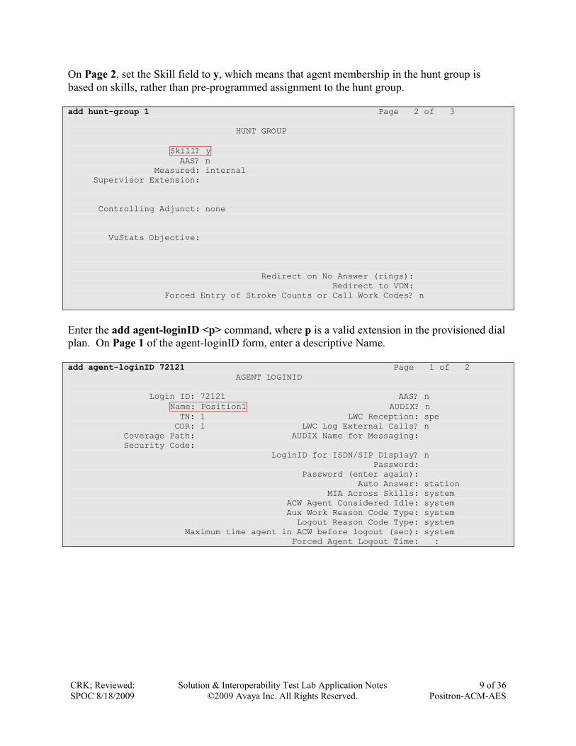
On Page 2, set the Skill field to y, which means that agent membership in the hunt group is
based on skills, rather than pre-programmed assignment to the hunt group.
add hunt-group 1 Page 2 of 3
HUNT GROUP
Skill? y
AAS? n
Measured: internal
Supervisor Extension:
Controlling Adjunct: none
VuStats Objective:
Redirect on No Answer (rings):
Redirect to VDN:
Forced Entry of Stroke Counts or Call Work Codes? n
Enter the add agent-loginID <p> command, where p is a valid extension in the provisioned dial
plan. On Page 1 of the agent-loginID form, enter a descriptive Name.
add agent-loginID 72121 Page 1 of 2
AGENT LOGINID
Login ID: 72121 AAS? n
Name: Position1 AUDIX? n
TN: 1 LWC Reception: spe
COR: 1 LWC Log External Calls? n
Coverage Path: AUDIX Name for Messaging:
Security Code:
LoginID for ISDN/SIP Display? n
Password:
Password (enter again):
Auto Answer: station
MIA Across Skills: system
ACW Agent Considered Idle: system
Aux Work Reason Code Type: system
Logout Reason Code Type: system
Maximum time agent in ACW before logout (sec): system
Forced Agent Logout Time: :
CRK; Reviewed:
SPOC 8/18/2009
Solution & Interoperability Test Lab Application Notes
©2009 Avaya Inc. All Rights Reserved.
10 of 36
Positron-ACM-AES
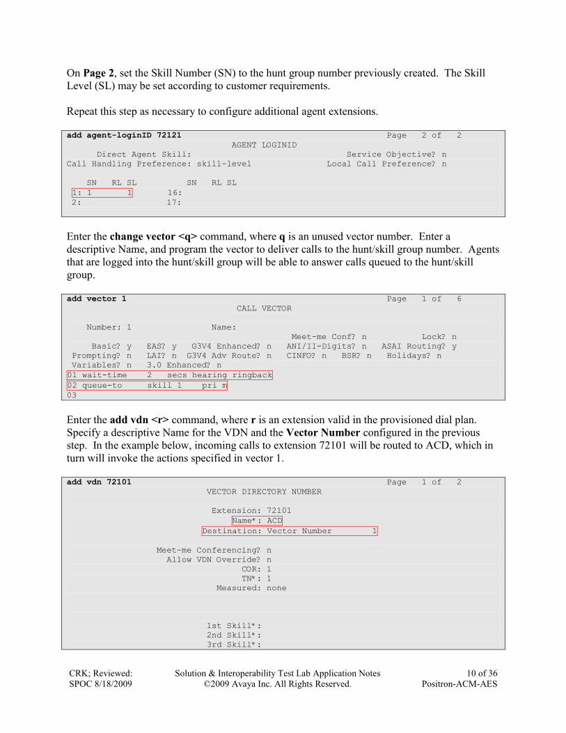
On Page 2, set the Skill Number (SN) to the hunt group number previously created. The Skill
Level (SL) may be set according to customer requirements.
Repeat this step as necessary to configure additional agent extensions.
add agent-loginID 72121 Page 2 of 2
AGENT LOGINID
Direct Agent Skill: Service Objective? n
Call Handling Preference: skill-level Local Call Preference? n
SN RL SL SN RL SL
1: 1 1 16:
2: 17:
Enter the change vector <q> command, where q is an unused vector number. Enter a
descriptive Name, and program the vector to deliver calls to the hunt/skill group number. Agents
that are logged into the hunt/skill group will be able to answer calls queued to the hunt/skill
group.
add vector 1 Page 1 of 6
CALL VECTOR
Number: 1 Name:
Meet-me Conf? n Lock? n
Basic? y EAS? y G3V4 Enhanced? n ANI/II-Digits? n ASAI Routing? y
Prompting? n LAI? n G3V4 Adv Route? n CINFO? n BSR? n Holidays? n
Variables? n 3.0 Enhanced? n
01 wait-time 2 secs hearing ringback
02 queue-to skill 1 pri m
03
Enter the add vdn <r> command, where r is an extension valid in the provisioned dial plan.
Specify a descriptive Name for the VDN and the Vector Number configured in the previous
step. In the example below, incoming calls to extension 72101 will be routed to ACD, which in
turn will invoke the actions specified in vector 1.
add vdn 72101 Page 1 of 2
VECTOR DIRECTORY NUMBER
Extension: 72101
Name*: ACD
Destination: Vector Number 1
Meet-me Conferencing? n
Allow VDN Override? n
COR: 1
TN*: 1
Measured: none
1st Skill*:
2nd Skill*:
3rd Skill*:

CRK; Reviewed:
SPOC 8/18/2009
Solution & Interoperability Test Lab Application Notes
©2009 Avaya Inc. All Rights Reserved.
11 of 36
Positron-ACM-AES
Enter the change feature-access-codes command. Define the Auto-In Access Code, Login
Access Code, Logout Access Code, and Aux Work Access Code.
change feature-access-codes Page 5 of 6
FEATURE ACCESS CODE (FAC)
Automatic Call Distribution Features
After Call Work Access Code: 120
Assist Access Code: 121
Auto-In Access Code: 122
Aux Work Access Code: 123
Login Access Code: 124
Logout Access Code: 125
Manual-in Access Code: 126
Service Observing Listen Only Access Code: 127
Service Observing Listen/Talk Access Code: 128
Add Agent Skill Access Code: 130
4.4. Configure Agent Stations
Enter the add station <s> command, where s is an extension valid in the provisioned dial plan.
On Page 1 of the STATION form, set the Type field to 2420 DCP set type, specify the Port,
enter a descriptive Name, specify the Security Code, and the IP Softphone field is set to y.
add station 72008 Page 1 of 5
STATION
Extension: 72008 Lock Messages? n BCC: 0
Type: 2420 Security Code: * TN: 1
Port: 001V303 Coverage Path 1: COR: 1
Name: Agent2 Phone Coverage Path 2: COS: 1
Hunt-to Station:
STATION OPTIONS
Time of Day Lock Table:
Loss Group: 2 Personalized Ringing Pattern: 1
Data Option: none Message Lamp Ext: 72008
Speakerphone: 2-way Mute Button Enabled? y
Display Language: english Expansion Module? n
Survivable COR: internal Media Complex Ext:
Survivable Trunk Dest? y IP SoftPhone? y
IP Video Softphone? n
Customizable Labels? y
On Page 4 of the STATION form, configure the following BUTTON ASSIGNMENTS:
auto-in
aux-work
autodial – for Login
autodial – for Logout
CRK; Reviewed:
SPOC 8/18/2009
Solution & Interoperability Test Lab Application Notes
©2009 Avaya Inc. All Rights Reserved.
12 of 36
Positron-ACM-AES
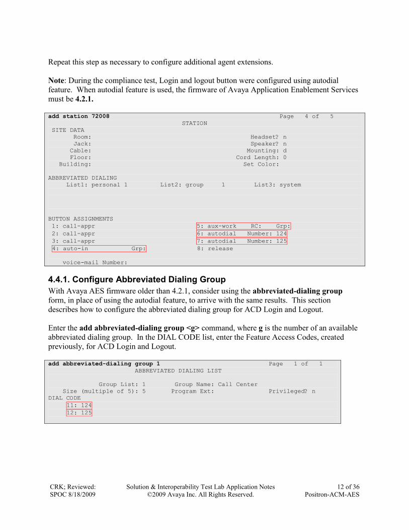
Repeat this step as necessary to configure additional agent extensions.
Note: During the compliance test, Login and logout button were configured using autodial
feature. When autodial feature is used, the firmware of Avaya Application Enablement Services
must be 4.2.1.
add station 72008 Page 4 of 5
STATION
SITE DATA
Room: Headset? n
Jack: Speaker? n
Cable: Mounting: d
Floor: Cord Length: 0
Building: Set Color:
ABBREVIATED DIALING
List1: personal 1 List2: group 1 List3: system
BUTTON ASSIGNMENTS
1: call-appr 5: aux-work RC: Grp:
2: call-appr 6: autodial Number: 124
3: call-appr 7: autodial Number: 125
4: auto-in Grp: 8: release
voice-mail Number:
4.4.1. Configure Abbreviated Dialing Group
With Avaya AES firmware older than 4.2.1, consider using the abbreviated-dialing group
form, in place of using the autodial feature, to arrive with the same results. This section
describes how to configure the abbreviated dialing group for ACD Login and Logout.
Enter the add abbreviated-dialing group <g> command, where g is the number of an available
abbreviated dialing group. In the DIAL CODE list, enter the Feature Access Codes, created
previously, for ACD Login and Logout.
add abbreviated-dialing group 1 Page 1 of 1
ABBREVIATED DIALING LIST
Group List: 1 Group Name: Call Center
Size (multiple of 5): 5 Program Ext: Privileged? n
DIAL CODE
11: 124
12: 125

CRK; Reviewed:
SPOC 8/18/2009
Solution & Interoperability Test Lab Application Notes
©2009 Avaya Inc. All Rights Reserved.
13 of 36
Positron-ACM-AES
On Page 4 of the STATION form, for ABBREVIATED DIALING List 2, enter the abbreviated
dialing group configured previously.
add station 72008 Page 4 of 5
STATION
SITE DATA
Room: Headset? n
Jack: Speaker? n
Cable: Mounting: d
Floor: Cord Length: 0
Building: Set Color:
ABBREVIATED DIALING
List1: personal 1 List2: group 1 List3: system
BUTTON ASSIGNMENTS
1: call-appr 5: aux-work RC: Grp:
2: call-appr 6: abrv-dial List: 2 DC: 11
3: call-appr 7: abrv-dial List: 2 DC: 12
4: auto-in Grp: 8: release
voice-mail Number:
4.5. Configure Analog trunk
This section describes an analog trunk between Positron CIM and Avaya S8300 Server w/ Avaya
G450 Media Gateway. Enter the add trunk-group <n> command; where n is an available
trunk-group number. Set the following values for specified fields, and retain the default values
for the remaining fields.
Group Type – co
Group Name – a descriptive name
TAC – a valid TAC
Incoming Destination – The destination extension where 911 calls will arrive at. During
the test, a VDN number, a virtual extension for shared line, or a terminal extension group
number was configured and tested.
Trunk Type: loop-start
add trunk-group 12 Page 1 of 21
TRUNK GROUP
Group Number: 12 Group Type: co CDR Reports: y
Group Name: 911 IN COR: 1 TN: 1 TAC: 1012
Direction: two-way Outgoing Display? n
Dial Access? n Busy Threshold: 255 Night Service:
Queue Length: 0 Country: 1 Incoming Destination: 72101
Comm Type: voice Auth Code? n Digit Absorption List:
Prefix-1? y Trunk Flash? n Toll Restricted? y
Trunk Type: loop-start
CRK; Reviewed:
SPOC 8/18/2009
Solution & Interoperability Test Lab Application Notes
©2009 Avaya Inc. All Rights Reserved.
14 of 36
Positron-ACM-AES
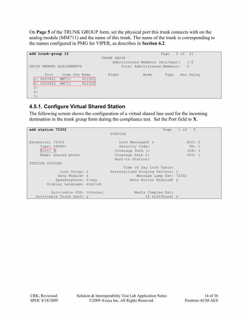
On Page 5 of the TRUNK GROUP form, set the physical port this trunk connects with on the
analog module (MM711) and the name of this trunk. The name of the trunk is corresponding to
the names configured in PMG for VIPER, as describes in Section 6.2.
add trunk-group 12 Page 5 of 21
TRUNK GROUP
Administered Members (min/max): 1/2
GROUP MEMBER ASSIGNMENTS Total Administered Members: 2
Port Code Sfx Name Night Mode Type Ans Delay
1: 001V401 MM711 911001
2: 001V402 MM711 911002
3:
4:
5:
4.5.1. Configure Virtual Shared Station
The following screen shows the configuration of a virtual shared line used for the incoming
destination in the trunk group form during the compliance test. Set the Port field to X.
add station 72302 Page 1 of 5
STATION
Extension: 72302 Lock Messages? n BCC: 0
Type: 6408D+ Security Code: TN: 1
Port: X Coverage Path 1: COR: 1
Name: shared phone Coverage Path 2: COS: 1
Hunt-to Station:
STATION OPTIONS
Time of Day Lock Table:
Loss Group: 2 Personalized Ringing Pattern: 1
Data Module? n Message Lamp Ext: 72302
Speakerphone: 2-way Mute Button Enabled? y
Display Language: english
Survivable COR: internal Media Complex Ext:
Survivable Trunk Dest? y IP SoftPhone? n
CRK; Reviewed:
SPOC 8/18/2009
Solution & Interoperability Test Lab Application Notes
©2009 Avaya Inc. All Rights Reserved.
15 of 36
Positron-ACM-AES
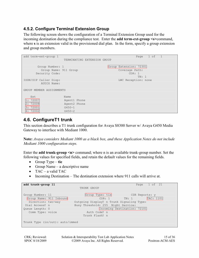
4.5.2. Configure Terminal Extension Group
The following screen shows the configuration of a Terminal Extension Group used for the
incoming destination during the compliance test. Enter the add term-ext-group <s>command,
where s is an extension valid in the provisioned dial plan. In the form, specify a group extension
and group members.
add term-ext-group 1 Page 1 of 1
TERMINATING EXTENSION GROUP
Group Number: 1 Group Extension: 72301
Group Name: 911 Group Coverage Path:
Security Code: COR: 1
TN: 1
ISDN/SIP Caller Disp: LWC Reception: none
AUDIX Name:
GROUP MEMBER ASSIGNMENTS
Ext Name
1: 72007 Agent1 Phone
2: 72008 Agent2 Phone
3: 72001 G450-1
4: 72002 G450-2
4.6. ConfigureT1 trunk
This section describes a T1 trunk configuration for Avaya S8300 Server w/ Avaya G450 Media
Gateway to interface with Mediant 1000.
Note: Avaya considers Mediant 1000 as a black box, and these Application Notes do not include
Mediant 1000 configuration steps.
Enter the add trunk-group <n> command; where n is an available trunk-group number. Set the
following values for specified fields, and retain the default values for the remaining fields.
Group Type – tie
Group Name – a descriptive name
TAC – a valid TAC
Incoming Destination – The destination extension where 911 calls will arrive at.
add trunk-group 11 Page 1 of 21
TRUNK GROUP
Group Number: 11 Group Type: tie CDR Reports: y
Group Name: 911 Inbound COR: 1 TN: 1 TAC: 1101
Direction: two-way Outgoing Display? n Trunk Signaling Type:
Dial Access? n Busy Threshold: 255 Night Service:
Queue Length: 0 Incoming Destination: 72101
Comm Type: voice Auth Code? n
Trunk Flash? n
Trunk Type (in/out): auto/immed
CRK; Reviewed:
SPOC 8/18/2009
Solution & Interoperability Test Lab Application Notes
©2009 Avaya Inc. All Rights Reserved.
16 of 36
Positron-ACM-AES
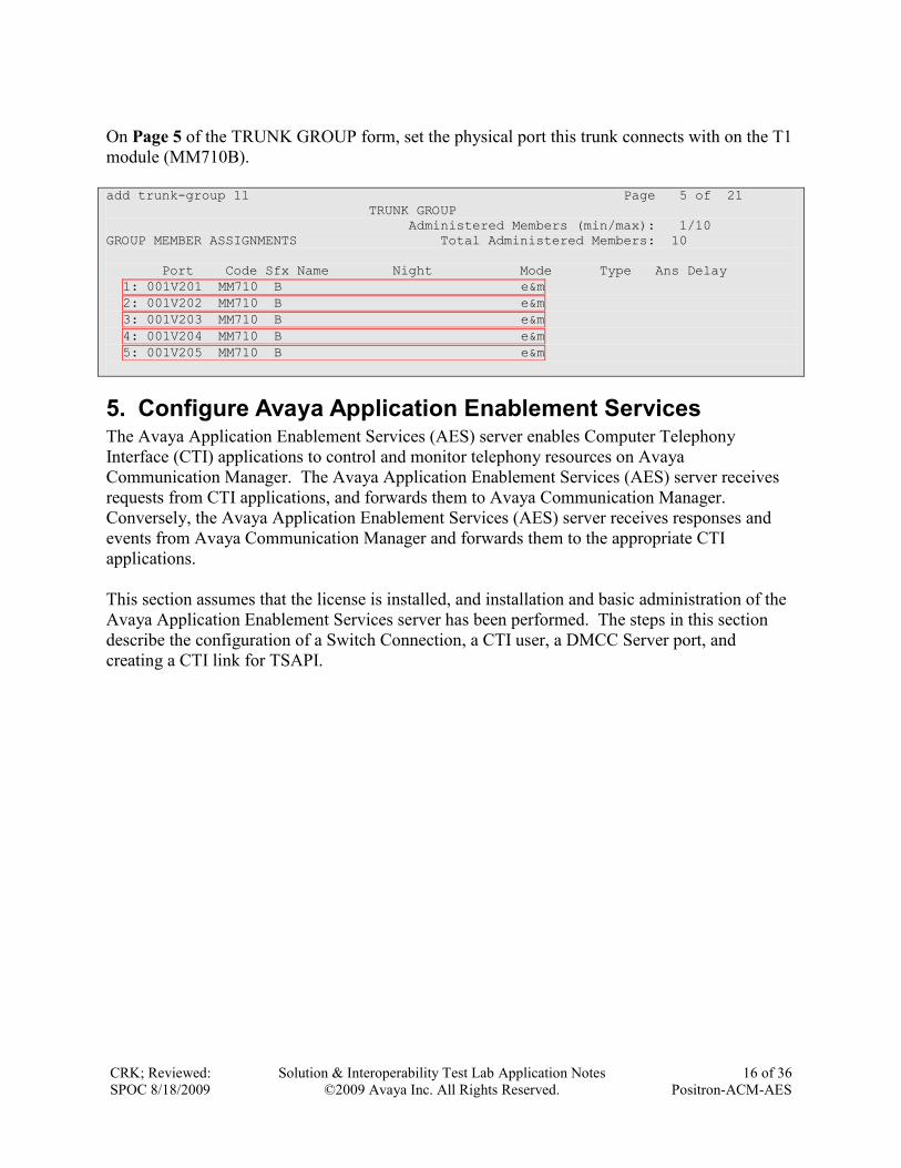
On Page 5 of the TRUNK GROUP form, set the physical port this trunk connects with on the T1
module (MM710B).
add trunk-group 11 Page 5 of 21
TRUNK GROUP
Administered Members (min/max): 1/10
GROUP MEMBER ASSIGNMENTS Total Administered Members: 10
Port Code Sfx Name Night Mode Type Ans Delay
1: 001V201 MM710 B e&m
2: 001V202 MM710 B e&m
3: 001V203 MM710 B e&m
4: 001V204 MM710 B e&m
5: 001V205 MM710 B e&m
5. Configure Avaya Application Enablement Services The Avaya Application Enablement Services (AES) server enables Computer Telephony
Interface (CTI) applications to control and monitor telephony resources on Avaya
Communication Manager. The Avaya Application Enablement Services (AES) server receives
requests from CTI applications, and forwards them to Avaya Communication Manager.
Conversely, the Avaya Application Enablement Services (AES) server receives responses and
events from Avaya Communication Manager and forwards them to the appropriate CTI
applications.
This section assumes that the license is installed, and installation and basic administration of the
Avaya Application Enablement Services server has been performed. The steps in this section
describe the configuration of a Switch Connection, a CTI user, a DMCC Server port, and
creating a CTI link for TSAPI.
CRK; Reviewed:
SPOC 8/18/2009
Solution & Interoperability Test Lab Application Notes
©2009 Avaya Inc. All Rights Reserved.
17 of 36
Positron-ACM-AES
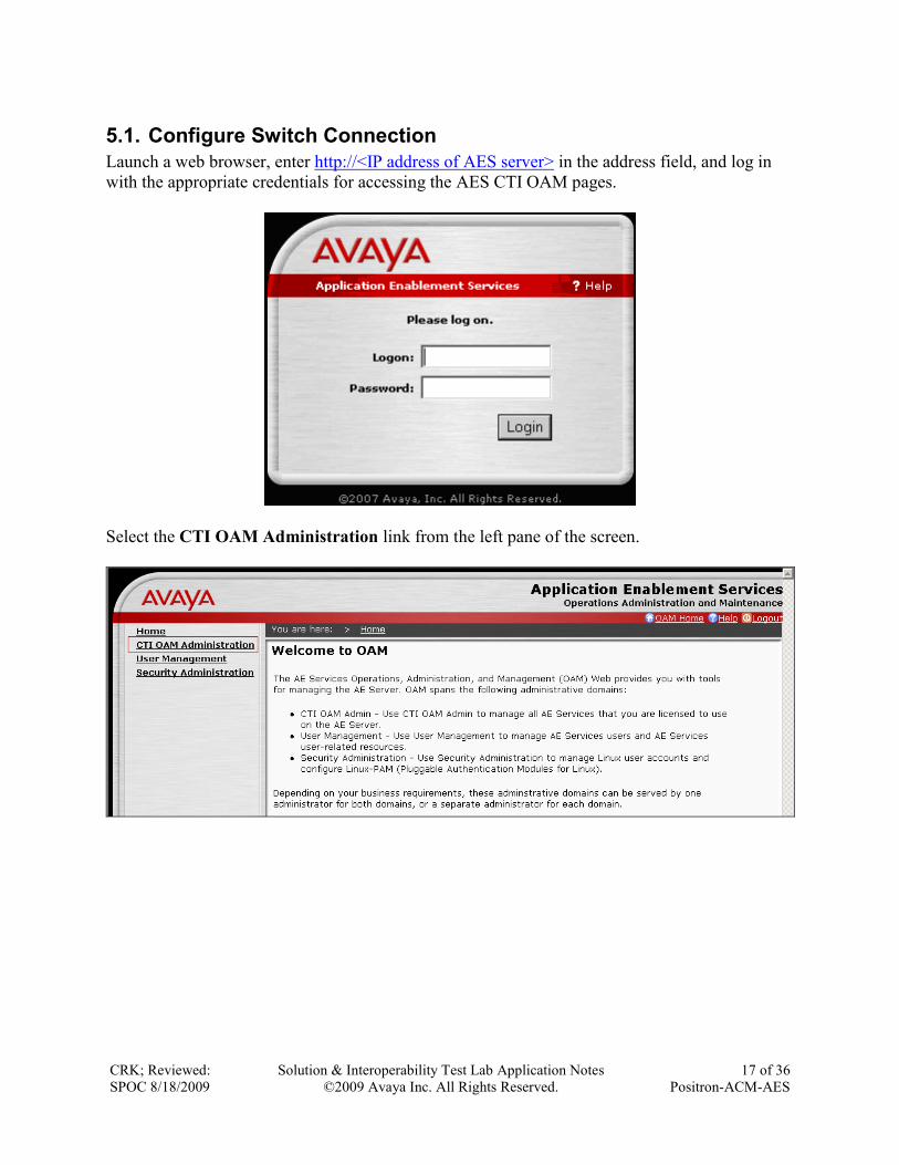
5.1. Configure Switch Connection
Launch a web browser, enter http://<IP address of AES server> in the address field, and log in
with the appropriate credentials for accessing the AES CTI OAM pages.
Select the CTI OAM Administration link from the left pane of the screen.
CRK; Reviewed:
SPOC 8/18/2009
Solution & Interoperability Test Lab Application Notes
©2009 Avaya Inc. All Rights Reserved.
18 of 36
Positron-ACM-AES
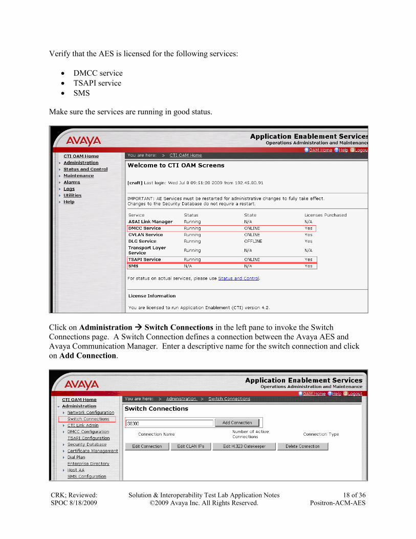
Verify that the AES is licensed for the following services:
DMCC service
TSAPI service
SMS
Make sure the services are running in good status.
Click on Administration Switch Connections in the left pane to invoke the Switch
Connections page. A Switch Connection defines a connection between the Avaya AES and
Avaya Communication Manager. Enter a descriptive name for the switch connection and click
on Add Connection.
CRK; Reviewed:
SPOC 8/18/2009
Solution & Interoperability Test Lab Application Notes
©2009 Avaya Inc. All Rights Reserved.
19 of 36
Positron-ACM-AES
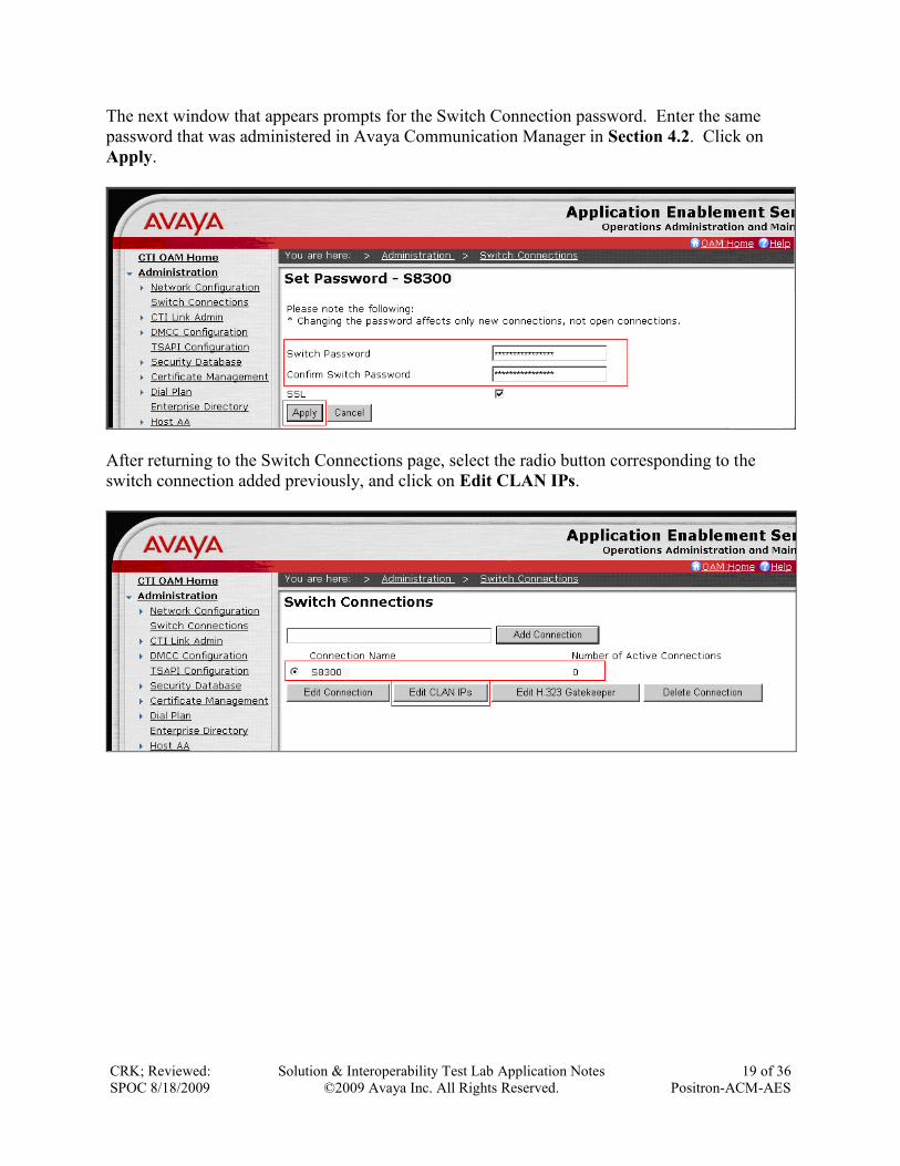
The next window that appears prompts for the Switch Connection password. Enter the same
password that was administered in Avaya Communication Manager in Section 4.2. Click on
Apply.
After returning to the Switch Connections page, select the radio button corresponding to the
switch connection added previously, and click on Edit CLAN IPs.
CRK; Reviewed:
SPOC 8/18/2009
Solution & Interoperability Test Lab Application Notes
©2009 Avaya Inc. All Rights Reserved.
20 of 36
Positron-ACM-AES
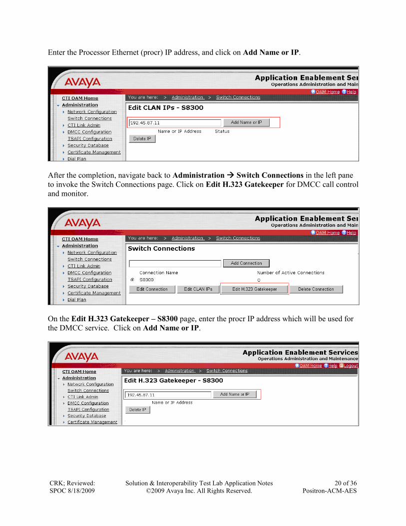
Enter the Processor Ethernet (procr) IP address, and click on Add Name or IP.
After the completion, navigate back to Administration Switch Connections in the left pane
to invoke the Switch Connections page. Click on Edit H.323 Gatekeeper for DMCC call control
and monitor.
On the Edit H.323 Gatekeeper – S8300 page, enter the procr IP address which will be used for
the DMCC service. Click on Add Name or IP.

CRK; Reviewed:
SPOC 8/18/2009
Solution & Interoperability Test Lab Application Notes
©2009 Avaya Inc. All Rights Reserved.
21 of 36
Positron-ACM-AES
5.2. Configure the TSAPI CTI link
Navigate to Administration CTI Link Admin TSAPI Links in the left pane, and click on
the Add Link button to create a TSAPI CTI link.
Select a Switch Connection using the drop down menu. The Switch Connection is configured in
Section 5.1. Select the Switch CTI Link Number using the drop down menu. Switch CTI Link
Number should match with the number configured in the cti-link form in Section 4.2. Click the
Apply Changes button. Default values may be used in the remaining fields.

CRK; Reviewed:
SPOC 8/18/2009
Solution & Interoperability Test Lab Application Notes
©2009 Avaya Inc. All Rights Reserved.
22 of 36
Positron-ACM-AES
5.3. Configure Tlink
Navigate to Administration Security Database CTI Users Tlinks. The Tlink doesn’t
need to be created manually. The Tlink should be created automatically, once the TSAPI CTI
link is created. This section just illustrates how to obtain a Tlink in the AES CTI OAM Home
page. The Tlink parameter will be used by the Positron VIPER solution.
5.4. Configure the CTI Users
The steps in this section describe the configuration of a CTI user. Launch a web browser, enter
http://<IP address of AES server> in the URL, and log in with the appropriate credentials to
access the relevant administration pages.
CRK; Reviewed:
SPOC 8/18/2009
Solution & Interoperability Test Lab Application Notes
©2009 Avaya Inc. All Rights Reserved.
23 of 36
Positron-ACM-AES
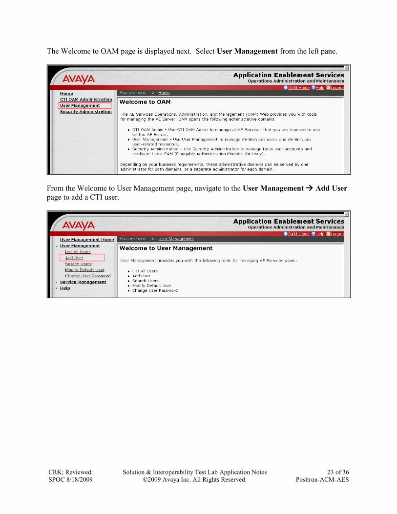
The Welcome to OAM page is displayed next. Select User Management from the left pane.
From the Welcome to User Management page, navigate to the User Management Add User
page to add a CTI user.
CRK; Reviewed:
SPOC 8/18/2009
Solution & Interoperability Test Lab Application Notes
©2009 Avaya Inc. All Rights Reserved.
24 of 36
Positron-ACM-AES
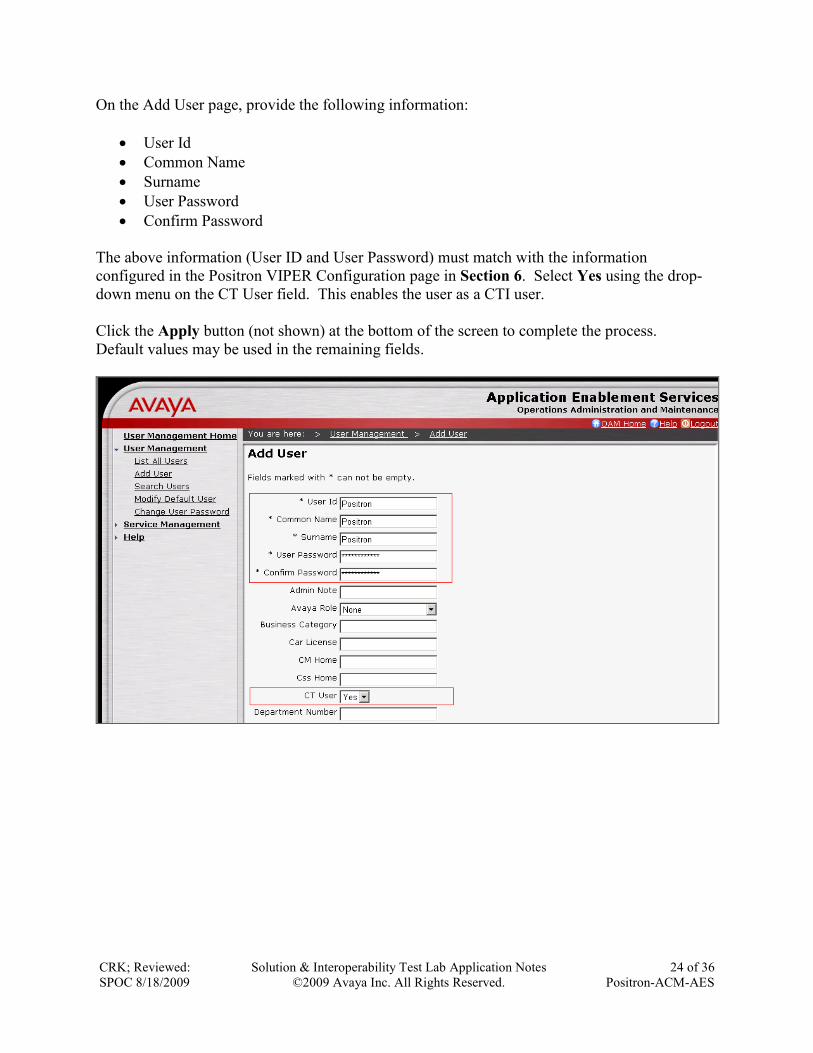
On the Add User page, provide the following information:
User Id
Common Name
Surname
User Password
Confirm Password
The above information (User ID and User Password) must match with the information
configured in the Positron VIPER Configuration page in Section 6. Select Yes using the drop-
down menu on the CT User field. This enables the user as a CTI user.
Click the Apply button (not shown) at the bottom of the screen to complete the process.
Default values may be used in the remaining fields.
CRK; Reviewed:
SPOC 8/18/2009
Solution & Interoperability Test Lab Application Notes
©2009 Avaya Inc. All Rights Reserved.
25 of 36
Positron-ACM-AES
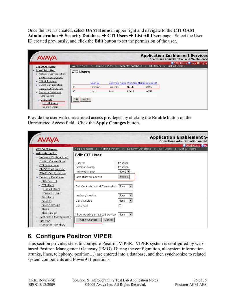
Once the user is created, select OAM Home in upper right and navigate to the CTI OAM
Administration Security Database CTI Users List All Users page. Select the User
ID created previously, and click the Edit button to set the permission of the user.
Provide the user with unrestricted access privileges by clicking the Enable button on the
Unrestricted Access field. Click the Apply Changes button.
6. Configure Positron VIPER This section provides steps to configure Positron VIPER. VIPER system is configured by web-
based Positron Management Gateway (PMG). During the configuration, all system information
(trunks, lines, telephony, position…) are entered into a database, and then synchronize to related
system components and Power911 positions.
CRK; Reviewed:
SPOC 8/18/2009
Solution & Interoperability Test Lab Application Notes
©2009 Avaya Inc. All Rights Reserved.
26 of 36
Positron-ACM-AES
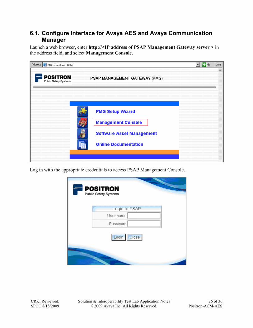
6.1. Configure Interface for Avaya AES and Avaya Communication Manager
Launch a web browser, enter http://<IP address of PSAP Management Gateway server > in
the address field, and select Management Console.
Log in with the appropriate credentials to access PSAP Management Console.
CRK; Reviewed:
SPOC 8/18/2009
Solution & Interoperability Test Lab Application Notes
©2009 Avaya Inc. All Rights Reserved.
27 of 36
Positron-ACM-AES
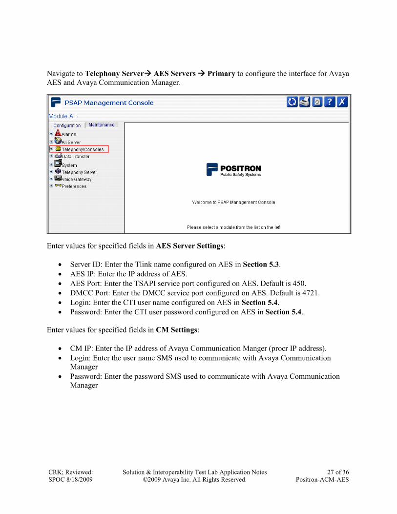
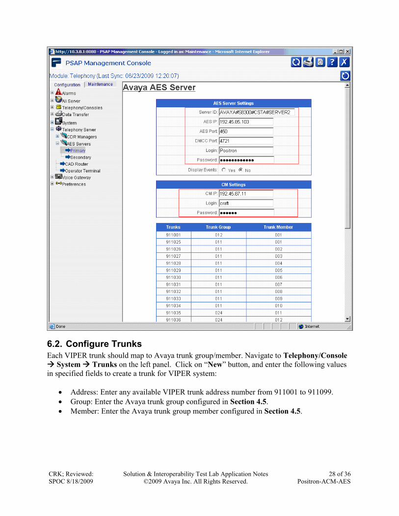
Navigate to Telephony Server AES Servers Primary to configure the interface for Avaya
AES and Avaya Communication Manager.
Enter values for specified fields in AES Server Settings:
Server ID: Enter the Tlink name configured on AES in Section 5.3.
AES IP: Enter the IP address of AES.
AES Port: Enter the TSAPI service port configured on AES. Default is 450.
DMCC Port: Enter the DMCC service port configured on AES. Default is 4721.
Login: Enter the CTI user name configured on AES in Section 5.4.
Password: Enter the CTI user password configured on AES in Section 5.4.
Enter values for specified fields in CM Settings:
CM IP: Enter the IP address of Avaya Communication Manger (procr IP address).
Login: Enter the user name SMS used to communicate with Avaya Communication
Manager
Password: Enter the password SMS used to communicate with Avaya Communication
Manager
CRK; Reviewed:
SPOC 8/18/2009
Solution & Interoperability Test Lab Application Notes
©2009 Avaya Inc. All Rights Reserved.
28 of 36
Positron-ACM-AES
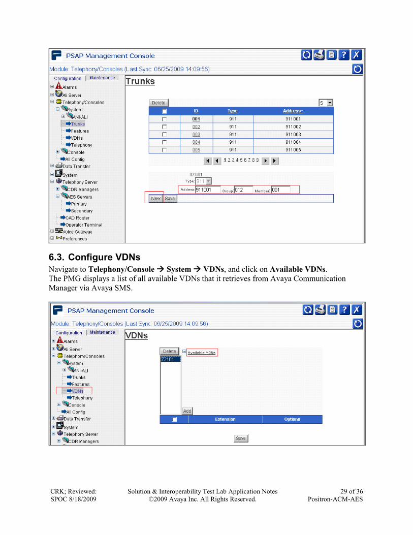
6.2. Configure Trunks
Each VIPER trunk should map to Avaya trunk group/member. Navigate to Telephony/Console
System Trunks on the left panel. Click on “New” button, and enter the following values
in specified fields to create a trunk for VIPER system:
Address: Enter any available VIPER trunk address number from 911001 to 911099.
Group: Enter the Avaya trunk group configured in Section 4.5.
Member: Enter the Avaya trunk group member configured in Section 4.5.
CRK; Reviewed:
SPOC 8/18/2009
Solution & Interoperability Test Lab Application Notes
©2009 Avaya Inc. All Rights Reserved.
29 of 36
Positron-ACM-AES
6.3. Configure VDNs
Navigate to Telephony/Console System VDNs, and click on Available VDNs.
The PMG displays a list of all available VDNs that it retrieves from Avaya Communication
Manager via Avaya SMS.
CRK; Reviewed:
SPOC 8/18/2009
Solution & Interoperability Test Lab Application Notes
©2009 Avaya Inc. All Rights Reserved.
30 of 36
Positron-ACM-AES
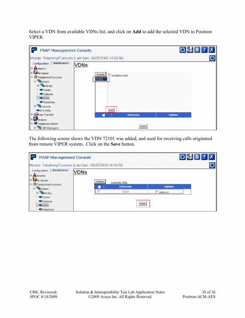
Select a VDN from available VDNs list, and click on Add to add the selected VDN to Positron
VIPER.
The following screen shows the VDN 72101 was added, and used for receiving calls originated
from remote VIPER system. Click on the Save button.
CRK; Reviewed:
SPOC 8/18/2009
Solution & Interoperability Test Lab Application Notes
©2009 Avaya Inc. All Rights Reserved.
31 of 36
Positron-ACM-AES
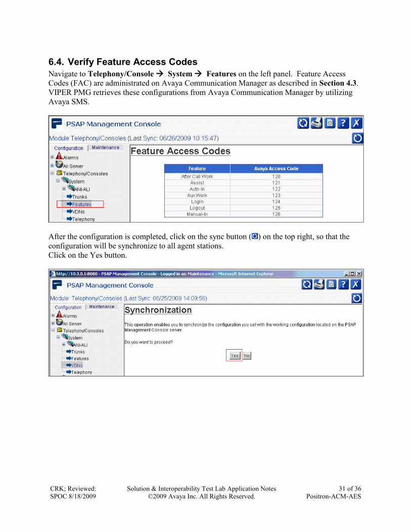
6.4. Verify Feature Access Codes
Navigate to Telephony/Console System Features on the left panel. Feature Access
Codes (FAC) are administrated on Avaya Communication Manager as described in Section 4.3.
VIPER PMG retrieves these configurations from Avaya Communication Manager by utilizing
Avaya SMS.
After the configuration is completed, click on the sync button ( ) on the top right, so that the
configuration will be synchronize to all agent stations.
Click on the Yes button.
CRK; Reviewed:
SPOC 8/18/2009
Solution & Interoperability Test Lab Application Notes
©2009 Avaya Inc. All Rights Reserved.
32 of 36
Positron-ACM-AES
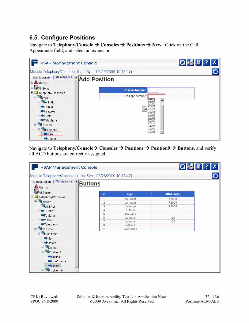
6.5. Configure Positions
Navigate to Telephony/Console Consoles Positions New. Click on the Call
Appearance field, and select an extension.
Navigate to Telephony/Console Consoles Positions Position9 Buttons, and verify
all ACD buttons are correctly assigned.

CRK; Reviewed:
SPOC 8/18/2009
Solution & Interoperability Test Lab Application Notes
©2009 Avaya Inc. All Rights Reserved.
33 of 36
Positron-ACM-AES
7. General Test Approach and Test Results The general test approach was to place 911 calls to Avaya S8300 Server w/ Avaya G450 Media
Gateway via Positron VIPER and exercise basic telephone operations. During the test, the
following features were verified:
ANI and ALI from Positron CIM.
ACD functions (Login, Logout, Aux-Work, Auto-In)
Hold / unHold a call.
Transfer calls (attended and unattended).
Conference calls up to 6 parties.
For serviceability testing, failures such as cable pulls and hardware resets were applied.
8. Verification Steps This section provides the steps that can be performed to verify proper configuration of Avaya
Communication Manager and Avaya AES.
8.1. Verify Avaya Communication Manager
Verify the status of the administered AES link by using the status aesvcs link command.
status aesvcs link
AE SERVICES LINK STATUS
Srvr/ AE Services Remote IP Remote Local Node Msgs Msgs
Link Server Port Sent Rcvd
01/01 server2 192. 45. 80.103 60336 CLAN-AES 208 197
Verify the Service State field of the administered TSAPI CTI link is in established state by using
the status aesvcs cti-link command.
status aesvcs cti-link
AE SERVICES CTI LINK STATUS
CTI Version Mnt AE Services Service Msgs Msgs
Link Busy Server State Sent Rcvd
4 4 no server2 established 15 15

CRK; Reviewed:
SPOC 8/18/2009
Solution & Interoperability Test Lab Application Notes
©2009 Avaya Inc. All Rights Reserved.
34 of 36
Positron-ACM-AES
8.2. Verify Avaya Application Enablement Services
From the CTI OAM Admin web pages, verify the status of the TSAPI and DMCC Services are
ONLINE, by selecting Status and Control Services Summary from the left pane.
9. Conclusion Positron VIPER was compliance tested with Avaya Aura
TM Communication Manager and Avaya
AuraTM
Application Enablement Services. Positron VIPER functioned properly for the feature
test. After a serviceability portion of the compliance test, Avaya recommends the following:
Avaya recommends using IP phones instead of DCP phones. This will eliminate losing
any existing 911 call when Avaya AuraTM
Communication Manager resets. By design,
Avaya AuraTM
Communication Manager resets and clears all TDM calls during the final
phase of reboot. Thus, the agent will lose the 911 call. Only the IP phone with shuffling
enabled will stay up during the whole reboot process. During the reboot process, any call
utilizing the media processor will lose the call, that includes analog, DCP, T1, or IP
without shuffling enabled. The same principal applies to the SIP environment.
If the solution utilizes DCP phones, the type of Avaya AuraTM
Communication Manager
should be S87xx Series paired system. This will also eliminate any call loss when Avaya
AuraTM
Communication Manager resets. The paired system is a fail-over (primary and
backup) system that existing calls will be transferred to the backup system when primary
lose the power.
10. Additional References The following Avaya product documentation can be found at http://support.avaya.com
[1] Administering Avaya Aura™ Communication Manager Release 5.2, Issue 5, May 2009,
Document Number 03-300509.
[2] Avaya Aura™ Communication Manager Screen Reference, Issue 1.0, May 2009, Document
Number 03-602878.
[3] Avaya Aura™ Application Enablement Services Administration and Maintenance Guide,
Release 4.2.2, May 2008, Document Number 02-300357.
CRK; Reviewed:
SPOC 8/18/2009
Solution & Interoperability Test Lab Application Notes
©2009 Avaya Inc. All Rights Reserved.
35 of 36
Positron-ACM-AES
The following document was provided by Positron.
[4] Application Notes for VIPER with Avaya Communication Manager and Avaya Application
Enablement Services
[5] Positron Power 911® Administrator User / Configuration Guide, Version5.1 rev. 3
MAY072008.
[6] Positron Configurator for Power 911® User Guide, Version 5.1, 925-195008-01E
[7] Positron IAP/PC®-G2 4-wire Card Setup Guide, Version 1.0, 925-195902-01E
CRK; Reviewed:
SPOC 8/18/2009
Solution & Interoperability Test Lab Application Notes
©2009 Avaya Inc. All Rights Reserved.
36 of 36
Positron-ACM-AES
©2009 Avaya Inc. All Rights Reserved.
Avaya and the Avaya Logo are trademarks of Avaya Inc. All trademarks identified by ® and ™
are registered trademarks or trademarks, respectively, of Avaya Inc. All other trademarks are the
property of their respective owners. The information provided in these Application Notes is
subject to change without notice. The configurations, technical data, and recommendations
provided in these Application Notes are believed to be accurate and dependable, but are
presented without express or implied warranty. Users are responsible for their application of any
products specified in these Application Notes.
Please e-mail any questions or comments pertaining to these Application Notes along with the
full title name and filename, located in the lower right corner, directly to the Avaya DevConnect
Program at [email protected].