Embed Size (px)
Citation preview
ENERGY AND COMFORT
Vent i la t ion Test ing
Positive and Negative Duct Accreditation (PANDA) System
Model PAN200 Series
Operation and Service Manual
ENERGY AND COMFORT
Copyright TSI Incorporated / 2012 / All rights reserved.
Address TSI Incorporated / 500 Cardigan Road / Shoreview, MN 55126 / USA
Fax No. (651) 490-3824
LIMITATION OF WARRANTY AND LIABILITY (effective June 2011) (For country-specific terms and conditions outside of the USA, please visit www.tsi.com.)
Seller warrants the goods sold hereunder, under normal use and service as described in the operator's manual, shall be free from defects in workmanship and material for 24 months, or if less, the length of time specified in the operator's manual, from the date of shipment to the customer. This warranty period is inclusive of any statutory warranty. This limited warranty is subject to the following exclusions and exceptions:
a. Hot-wire or hot-film sensors used with research anemometers, and certain other components when indicated in specifications, are warranted for 90 days from the date of shipment;
b. Pumps are warranted for hours of operation as set forth in product or operator’s manuals; c. Parts repaired or replaced as a result of repair services are warranted to be free from defects
in workmanship and material, under normal use, for 90 days from the date of shipment; d. Seller does not provide any warranty on finished goods manufactured by others or on any
fuses, batteries or other consumable materials. Only the original manufacturer's warranty applies;
e. Unless specifically authorized in a separate writing by Seller, Seller makes no warranty with respect to, and shall have no liability in connection with, goods which are incorporated into other products or equipment, or which are modified by any person other than Seller.
The foregoing is IN LIEU OF all other warranties and is subject to the LIMITATIONS stated herein. NO OTHER EXPRESS OR IMPLIED WARRANTY OF FITNESS FOR PARTICULAR PURPOSE OR MERCHANTABILITY IS MADE. WITH RESPECT TO SELLER’S BREACH OF THE IMPLIED WARRANTY AGAINST INFRINGEMENT, SAID WARRANTY IS LIMITED TO CLAIMS OF DIRECT INFRINGEMENT AND EXCLUDES CLAIMS OF CONTRIBUTORY OR INDUCED INFRINGEMENTS. BUYER’S EXCLUSIVE REMEDY SHALL BE THE RETURN OF THE PURCHASE PRICE DISCOUNTED FOR REASONABLE WEAR AND TEAR OR AT SELLER’S OPTION REPLACEMENT OF THE GOODS WITH NON-INFRINGING GOODS.
TO THE EXTENT PERMITTED BY LAW, THE EXCLUSIVE REMEDY OF THE USER OR BUYER, AND THE LIMIT OF SELLER'S LIABILITY FOR ANY AND ALL LOSSES, INJURIES, OR DAMAGES CONCERNING THE GOODS (INCLUDING CLAIMS BASED ON CONTRACT, NEGLIGENCE, TORT, STRICT LIABILITY OR OTHERWISE) SHALL BE THE RETURN OF GOODS TO SELLER AND THE REFUND OF THE PURCHASE PRICE, OR, AT THE OPTION OF SELLER, THE REPAIR OR REPLACEMENT OF THE GOODS. IN THE CASE OF SOFTWARE, SELLER WILL REPAIR OR REPLACE DEFECTIVE SOFTWARE OR IF UNABLE TO DO SO, WILL REFUND THE PURCHASE PRICE OF THE SOFTWARE. IN NO EVENT SHALL SELLER BE LIABLE FOR LOST PROFITS OR ANY SPECIAL, CONSEQUENTIAL OR INCIDENTAL DAMAGES. SELLER SHALL NOT BE RESPONSIBLE FOR INSTALLATION, DISMANTLING OR REINSTALLATION COSTS OR CHARGES. No Action, regardless of form, may be brought against Seller more than 12 months after a cause of action has accrued. The goods returned under warranty to Seller's factory shall be at Buyer's risk of loss, and will be returned, if at all, at Seller's risk of loss.
Buyer and all users are deemed to have accepted this LIMITATION OF WARRANTY AND LIABILITY, which contains the complete and exclusive limited warranty of Seller. This LIMITATION OF WARRANTY AND LIABILITY may not be amended, modified or its terms waived, except by writing signed by an Officer of Seller.
Service Policy Knowing that inoperative or defective instruments are as detrimental to TSI as they are to our customers, our service policy is designed to give prompt attention to any problems. If any malfunction is discovered, please contact your nearest sales office or representative, or call Customer Service department at +44 (0) 149 4 459200 (UK), (800) 874-2811 (USA), or (1) 651-490-2811 (International).
iii
CONTENTS
CHAPTER 1 UNPACKING AND PARTS IDENTIFICATION ............. 1
CHAPTER 2 PREPARING PAN200 SYSTEM FOR AIR DUCT LEAK TESTING ................................................................ 5
CHAPTER 3 PERFORMING A DUCT LEAKAGE TEST ................ 11
Measuring Duct Static Pressure ................................................... 11
Measuring Duct Leakage Flow ..................................................... 12
Turning on the PAN200 Duct Leakage Tester.............................. 12
Using Leakage Test Application in the Model 9565-P .................. 13
Troubleshooting Guide ................................................................. 16
APPENDIX A SPECIFICATIONS ..................................................... 17
APPENDIX B LEAKAGE TESTING STANDARDS HIGHLIGHTS ... 21
Standards Supported .................................................................... 21
EU Standards ............................................................................... 22
US Standards ............................................................................... 25
APPENDIX C TYPICAL SETUP....................................................... 29
APPENDIX D PROCEDURE FOR USING SMOKE PELLETS IN LEAKAGE TESTERS ................................................................... 31

iv
(This page intentionally left blank)
1
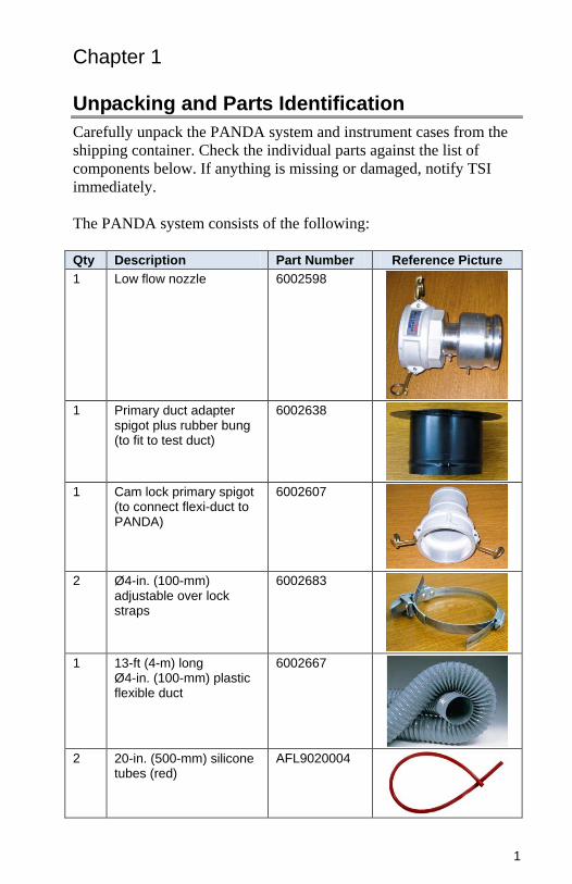
Chapter 1 Unpacking and Parts Identification
Carefully unpack the PANDA system and instrument cases from the
shipping container. Check the individual parts against the list of
components below. If anything is missing or damaged, notify TSI
immediately.
The PANDA system consists of the following:
Qty Description Part Number Reference Picture
1 Low flow nozzle 6002598
1 Primary duct adapter spigot plus rubber bung (to fit to test duct)
6002638
1 Cam lock primary spigot (to connect flexi-duct to PANDA)
6002607
2 Ø4-in. (100-mm) adjustable over lock straps
6002683
1 13-ft (4-m) long Ø4-in. (100-mm) plastic flexible duct
6002667
2 20-in. (500-mm) silicone tubes (red)
AFL9020004
2 Chapter 1
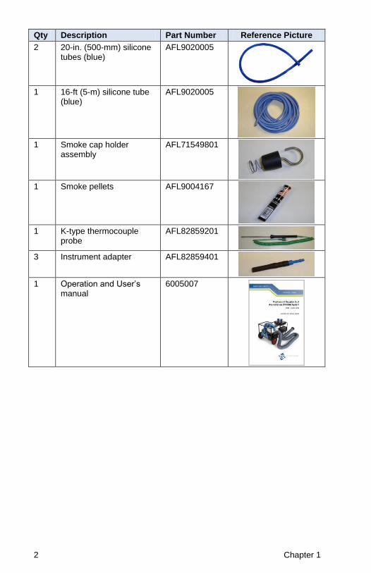
Qty Description Part Number Reference Picture
2 20-in. (500-mm) silicone tubes (blue)
AFL9020005
1 16-ft (5-m) silicone tube (blue)
AFL9020005
1 Smoke cap holder assembly
AFL71549801
1 Smoke pellets AFL9004167
1 K-type thermocouple probe
AFL82859201
3 Instrument adapter AFL82859401
1 Operation and User’s manual
6005007
Unpacking and Parts Identification 3
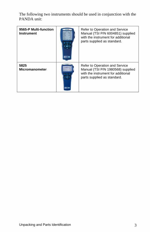
The following two instruments should be used in conjunction with the
PANDA unit:
9565-P Multi-function Instrument
Refer to Operation and Service Manual (TSI P/N 6004851) supplied with the instrument for additional parts supplied as standard.
5825 Micromanometer
Refer to Operation and Service Manual (TSI P/N 1980568) supplied with the instrument for additional parts supplied as standard.

4 Chapter 1
(This page intentionally left blank)
5
Chapter 2 Preparing PAN200 System for Air Duct Leak Testing
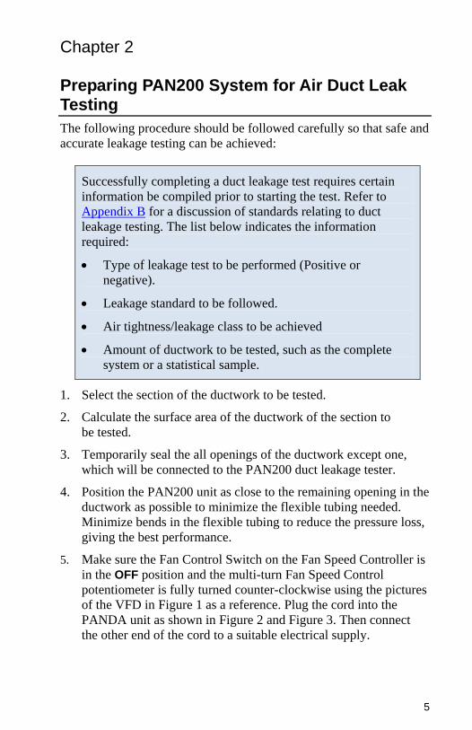
The following procedure should be followed carefully so that safe and
accurate leakage testing can be achieved:
Successfully completing a duct leakage test requires certain
information be compiled prior to starting the test. Refer to
Appendix B for a discussion of standards relating to duct
leakage testing. The list below indicates the information
required:
Type of leakage test to be performed (Positive or
negative).
Leakage standard to be followed.
Air tightness/leakage class to be achieved
Amount of ductwork to be tested, such as the complete
system or a statistical sample.
1. Select the section of the ductwork to be tested.
2. Calculate the surface area of the ductwork of the section to
be tested.
3. Temporarily seal the all openings of the ductwork except one,
which will be connected to the PAN200 duct leakage tester.
4. Position the PAN200 unit as close to the remaining opening in the
ductwork as possible to minimize the flexible tubing needed.
Minimize bends in the flexible tubing to reduce the pressure loss,
giving the best performance.
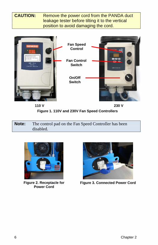
5. Make sure the Fan Control Switch on the Fan Speed Controller is
in the OFF position and the multi-turn Fan Speed Control
potentiometer is fully turned counter-clockwise using the pictures
of the VFD in Figure 1 as a reference. Plug the cord into the
PANDA unit as shown in Figure 2 and Figure 3. Then connect
the other end of the cord to a suitable electrical supply.
6 Chapter 2
CAUTION: Remove the power cord from the PANDA duct leakage tester before tilting it to the vertical position to avoid damaging the cord.
110 V
230 V
Figure 1. 110V and 230V Fan Speed Controllers
Note: The control pad on the Fan Speed Controller has been
disabled.
Figure 2. Receptacle for Power Cord
Figure 3. Connected Power Cord
Fan Speed
Control
Fan Control
Switch
On/Off
Switch
Preparing PAN200 System for Air Duct Leak Testing 7
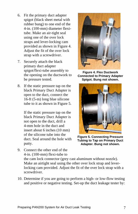
6. Fit the primary duct adapter
spigot (black sheet metal with
rubber bung) to one end of the
4-in. (100-mm) diameter flexi-
tube. Make an air-tight seal
using one of the over lock
straps and lever-locking cam
provided as shown in Figure 4.
Adjust the fit of the over lock
strap with a screwdriver.
7. Securely attach the black
primary duct adapter
spigot/flexi-tube assembly to
the opening on the ductwork to
be pressure tested.
Figure 4. Flex Ductwork
Connected to Primary Adapter Spigot. Bung not shown.
8. If the static pressure tap on the
black Primary Duct Adapter is
open to the duct, connect the
16-ft (5-m) long blue silicone
tube to it as shown in Figure 5.
If the static pressure tap on the
black Primary Duct Adapter is
not open to the duct, drill a
4-mm hole in the duct and
insert about 6 inches (10 mm)
of the silicone tube into the
duct. Seal around the hole with
putty.
9. Connect the other end of the
4-in. (100-mm) flexi-tube to
Figure 5. Connecting Pressure Tubing to Tap on Primary Duct
Adapter. Bung not shown.
the cam lock connector (grey cast aluminum without nozzle).
Make an airtight seal using the other over lock strap and lever-
locking cam provided. Adjust the fit of the over lock strap with a
screwdriver.
10. Determine if you are going to perform a high- or low-flow testing
and positive or negative testing. Set-up the duct leakage tester by:
8 Chapter 2
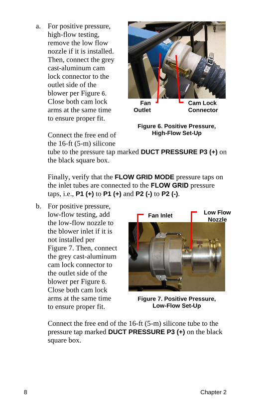
a. For positive pressure,
high-flow testing,
remove the low flow
nozzle if it is installed.
Then, connect the grey
cast-aluminum cam
lock connector to the
outlet side of the
blower per Figure 6.
Close both cam lock
arms at the same time
to ensure proper fit.
Connect the free end of
the 16-ft (5-m) silicone
Figure 6. Positive Pressure, High-Flow Set-Up
tube to the pressure tap marked DUCT PRESSURE P3 (+) on
the black square box.
Finally, verify that the FLOW GRID MODE pressure taps on
the inlet tubes are connected to the FLOW GRID pressure
taps, i.e., P1 (+) to P1 (+) and P2 (-) to P2 (-).
b. For positive pressure,
low-flow testing, add
the low-flow nozzle to
the blower inlet if it is
not installed per
Figure 7. Then, connect
the grey cast-aluminum
cam lock connector to
the outlet side of the
blower per Figure 6.
Close both cam lock
arms at the same time
to ensure proper fit.
Figure 7. Positive Pressure, Low-Flow Set-Up
Connect the free end of the 16-ft (5-m) silicone tube to the
pressure tap marked DUCT PRESSURE P3 (+) on the black
square box.
Fan
Outlet
Cam Lock
Connector
Low Flow
Nozzle Fan Inlet
Preparing PAN200 System for Air Duct Leak Testing 9
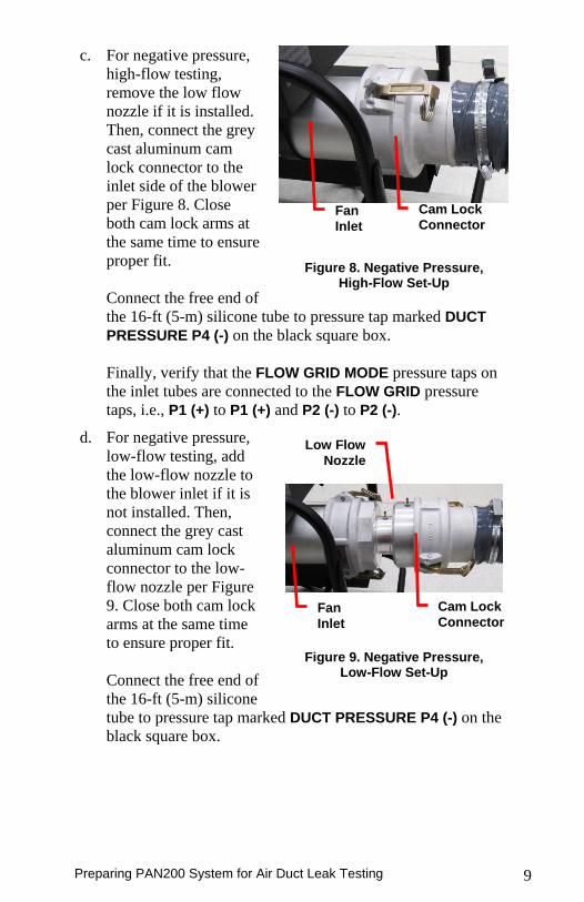
c. For negative pressure,
high-flow testing,
remove the low flow
nozzle if it is installed.
Then, connect the grey
cast aluminum cam
lock connector to the
inlet side of the blower
per Figure 8. Close
both cam lock arms at
the same time to ensure
proper fit.
Connect the free end of
Figure 8. Negative Pressure, High-Flow Set-Up
the 16-ft (5-m) silicone tube to pressure tap marked DUCT
PRESSURE P4 (-) on the black square box.
Finally, verify that the FLOW GRID MODE pressure taps on
the inlet tubes are connected to the FLOW GRID pressure
taps, i.e., P1 (+) to P1 (+) and P2 (-) to P2 (-).
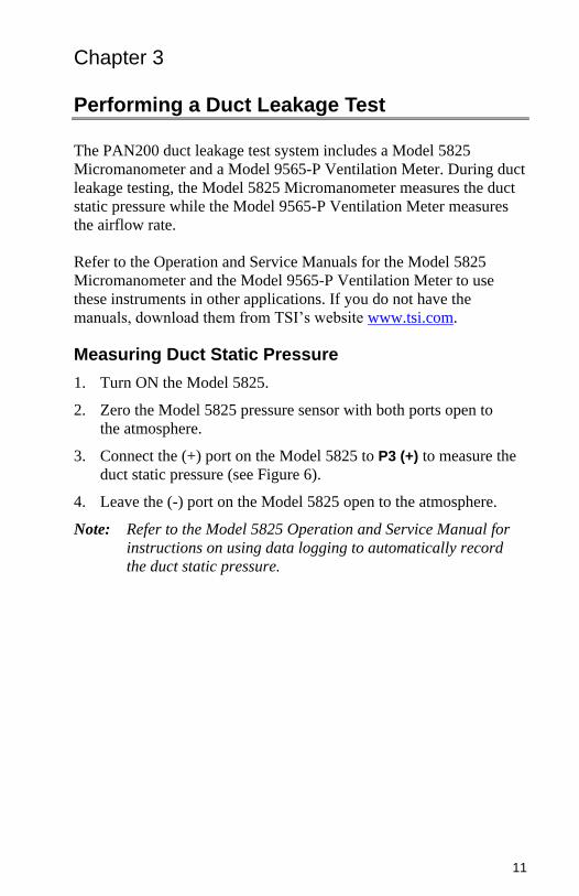
d. For negative pressure,
low-flow testing, add
the low-flow nozzle to
the blower inlet if it is
not installed. Then,
connect the grey cast
aluminum cam lock
connector to the low-
flow nozzle per Figure
9. Close both cam lock
arms at the same time
to ensure proper fit.
Connect the free end of
the 16-ft (5-m) silicone
Figure 9. Negative Pressure, Low-Flow Set-Up
tube to pressure tap marked DUCT PRESSURE P4 (-) on the
black square box.
Fan
Inlet
Cam Lock
Connector
Fan
Inlet
Low Flow
Nozzle
Cam Lock
Connector

10 Chapter 2
(This page intentionally left blank)
11
Chapter 3 Performing a Duct Leakage Test
The PAN200 duct leakage test system includes a Model 5825
Micromanometer and a Model 9565-P Ventilation Meter. During duct
leakage testing, the Model 5825 Micromanometer measures the duct
static pressure while the Model 9565-P Ventilation Meter measures
the airflow rate.
Refer to the Operation and Service Manuals for the Model 5825
Micromanometer and the Model 9565-P Ventilation Meter to use
these instruments in other applications. If you do not have the
manuals, download them from TSI’s website www.tsi.com.
Measuring Duct Static Pressure
1. Turn ON the Model 5825.
2. Zero the Model 5825 pressure sensor with both ports open to
the atmosphere.
3. Connect the (+) port on the Model 5825 to P3 (+) to measure the
duct static pressure (see Figure 6).
4. Leave the (-) port on the Model 5825 open to the atmosphere.
Note: Refer to the Model 5825 Operation and Service Manual for
instructions on using data logging to automatically record
the duct static pressure.
12 Chapter 3
Measuring Duct Leakage Flow
Turning on the PAN200 Duct Leakage Tester
1. Switch the PANDA unit on.
a. For 230V models position the Mains Power switch of the
inverter to the ON position to power the Inverter speed
controller. The Fan motor is not energized.
b. 110V models do not include a separate power switch. The
PANDA unit is turned on when the power cord is plugged in.
2. Position the Fan Control switch to the RUN position to energize
the fan.
3. Increase the fan to the desired speed by turning the Fan Speed
Controller clockwise. To decrease the fan speed, turn the Fan
Speed controller counter-clockwise.
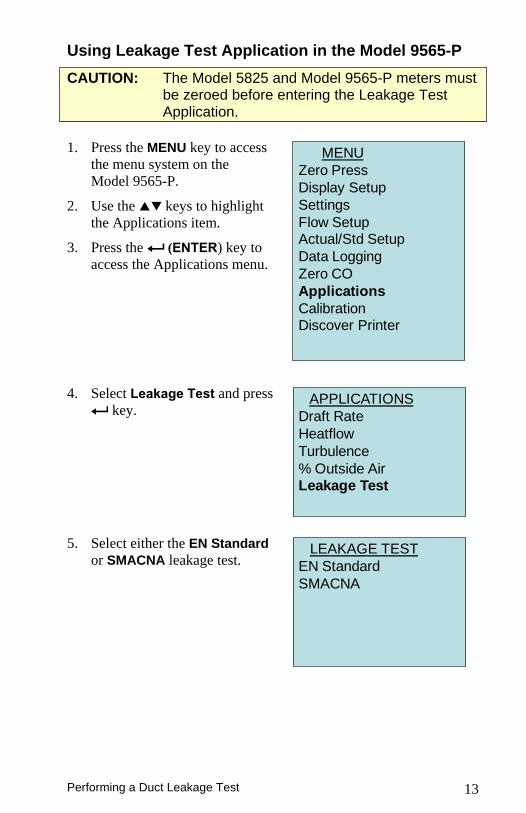
1. Turn ON Model 9565-P.
2. Zero the Model 9565-P
pressure sensor with both
ports open to the atmosphere.
3. Connect the Model 9565-P to
the PAN200 by connecting
the (+) and (-) ports on the
Model 9565-P to the P1 (+)
and P2 (+) ports located
inside the black box of the
PAN200as shown in
Figure 10.
Figure 10. Connecting Instruments to PANDA Tester in
High Flow Mode
4. Connect the thermocouple to
the Model 9565-P.
5. Insert the thermocouple
probe into the blower inlet
through the hole marked TC1
as shown in Figure 11.
Figure 11. Thermocouple Insertion Hole
Thermocouple
Hole
Performing a Duct Leakage Test 13
Using Leakage Test Application in the Model 9565-P
CAUTION: The Model 5825 and Model 9565-P meters must be zeroed before entering the Leakage Test Application.
1. Press the MENU key to access
the menu system on the
Model 9565-P.
2. Use the keys to highlight
the Applications item.
3. Press the (ENTER) key to
access the Applications menu.
MENU
Zero Press
Display Setup
Settings
Flow SetupActual/Std Setup
Data Logging
Zero CO
Applications
CalibrationDiscover Printer
4. Select Leakage Test and press
key. APPLICATIONS
Draft Rate
Heatflow
Turbulence
% Outside AirLeakage Test
5. Select either the EN Standard
or SMACNA leakage test. LEAKAGE TEST
EN Standard
SMACNA
14 Chapter 3
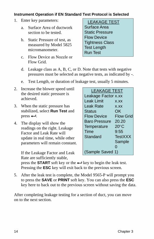
Instrument Operation if EN Standard Test Protocol is Selected
1. Enter key parameters:
a. Surface Area of ductwork
section to be tested.
b. Static Pressure of test, as
measured by Model 5825
micromanometer.
c. Flow Device as Nozzle or
Flow Grid.
LEAKAGE TEST
Surface Area
Static Pressure
Flow Device
Tightness ClassTest Length
Run Test
d. Leakage class as A, B, C, or D. Note that tests with negative
pressures must be selected as negative tests, as indicated by -.
e. Test Length, or duration of leakage test, usually 5 minutes.
2. Increase the blower speed until
the desired static pressure is
achieved.
3. When the static pressure has
stabilized, select Run Test and
press .
4. The display will show the
readings on the right. Leakage
Factor and Leak Rate will
update in real time, while other
parameters will remain constant.
If the Leakage Factor and Leak
Rate are sufficiently stable,
LEAKAGE TEST
Leakage Factor x.xx
Leak Limit x.xx
Leak Rate x.xx
Status OKFlow Device Flow Grid
Baro Pressure 20.20
Temperature 20C
Time 9:55
Standard TestXXXSample
0
(Sample Saved 1)
press the START soft key or the key to begin the leak test.
Pressing the ESC key will exit back to the previous screen.
5. After the leak test is complete, the Model 9565-P will prompt you
to press the SAVE or PRINT soft key. You can also press the ESC
key here to back out to the previous screen without saving the data.
After completing leakage testing for a section of duct, you can move
on to the next section.
Performing a Duct Leakage Test 15
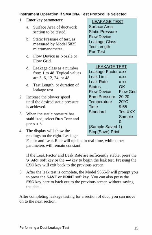
Instrument Operation if SMACNA Test Protocol is Selected
1. Enter key parameters:
a. Surface Area of ductwork
section to be tested.
b. Static Pressure of test, as
measured by Model 5825
micromanometer.
c. Flow Device as Nozzle or
Flow Grid.
d. Leakage class as a number
from 1 to 48. Typical values
are 3, 6, 12, 24, or 48.
e. Test Length, or duration of
leakage test.
2. Increase the blower speed
until the desired static pressure
is achieved.
3. When the static pressure has
stabilized, select Run Test and
press .
4. The display will show the
readings on the right. Leakage
LEAKAGE TEST
Surface Area
Static Pressure
Flow Device
Leakage ClassTest Length
Run Test
LEAKAGE TEST
Leakage Factor x.xx
Leak Limit x.xx
Leak Rate x.xx
Status OKFlow Device Flow Grid
Baro Pressure 20.20
Temperature 20C
Time 9:55
Standard TestXXXSample
0
(Sample Saved 1)
Stop(Save) Print
Factor and Leak Rate will update in real time, while other
parameters will remain constant.
If the Leak Factor and Leak Rate are sufficiently stable, press the
START soft key or the key to begin the leak test. Pressing the
ESC key will exit back to the previous screen.
5. After the leak test is complete, the Model 9565-P will prompt you
to press the SAVE or PRINT soft key. You can also press the
ESC key here to back out to the previous screen without saving
the data.
After completing leakage testing for a section of duct, you can move
on to the next section.
16 Chapter 3
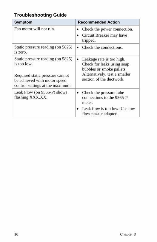
Troubleshooting Guide
Symptom Recommended Action
Fan motor will not run. Check the power connection.
Circuit Breaker may have
tripped.
Static pressure reading (on 5825)
is zero. Check the connections.
Static pressure reading (on 5825)
is too low.
Required static pressure cannot
be achieved with motor speed
control settings at the maximum.
Leakage rate is too high.
Check for leaks using soap
bubbles or smoke pallets.
Alternatively, test a smaller
section of the ductwork.
Leak Flow (on 9565-P) shows
flashing XXX.XX. Check the pressure tube
connections to the 9565-P
meter.
Leak flow is too low. Use low
flow nozzle adapter.
17
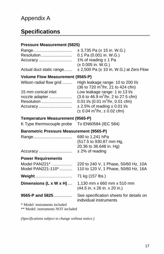
Appendix A Specifications
Pressure Measurement (5825)
Range .................................. ± 3,735 Pa (± 15 in. W.G.) Resolution ........................... 0.1 Pa (0.001 in. W.G.) Accuracy ............................. 1% of reading ± 1 Pa
(± 0.005 in. W.G.) Actual duct static range ....... ± 2,500 Pa (± 10 in. W.G.) at Zero Flow
Volume Flow Measurement (9565-P)
Wilson radial flow grid ......... High leakage range: 10 to 200 l/s (36 to 720 m
3/hr, 21 to 424 cfm)
15 mm conical inlet nozzle adapter ....................
Low leakage range: 1 to 13 l/s (3.6 to 46.9 m
3/hr, 2 to 27.5 cfm)
Resolution ........................... 0.01 l/s (0.01 m3/hr, 0.01 cfm)
Accuracy ............................. ± 2.5% of reading ± 0.01 l/s (± 0.04 m
3/hr, ± 0.02 cfm)
Temperature Measurement (9565-P)
K Type thermocouple probe To EN60584 (IEC 584)
Barometric Pressure Measurement (9565-P)
Range .................................. 690 to 1,241 hPa (517.5 to 930.87 mm Hg, 20.36 to 36.648 in. Hg)
Accuracy ............................. ± 2% of reading
Power Requirements
Model PAN221* .................. 220 to 240 V, 1 Phase, 50/60 Hz, 10A Model PAN221-110* ........... 110 to 120 V, 1 Phase, 50/60 Hz, 16A
Weight ................................ 71 kg (157 lbs.)
Dimensions (L x W x H) .... 1,130 mm x 660 mm x 510 mm (44.5 in. x 26 in. x 20 in.)
9565-P and 5825 ................ See specification sheets for details on individual instruments
* Model: instruments included
** Model: instruments NOT included
(Specifications subject to change without notice.)
18 Appendix A
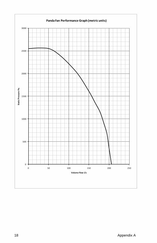
0
500
1000
1500
2000
2500
3000
0 50 100 150 200 250
Stat
ic P
ress
ure
Pa.
Volume Flow l/s
Panda Fan Performance Graph (metric units)
Specifications 19
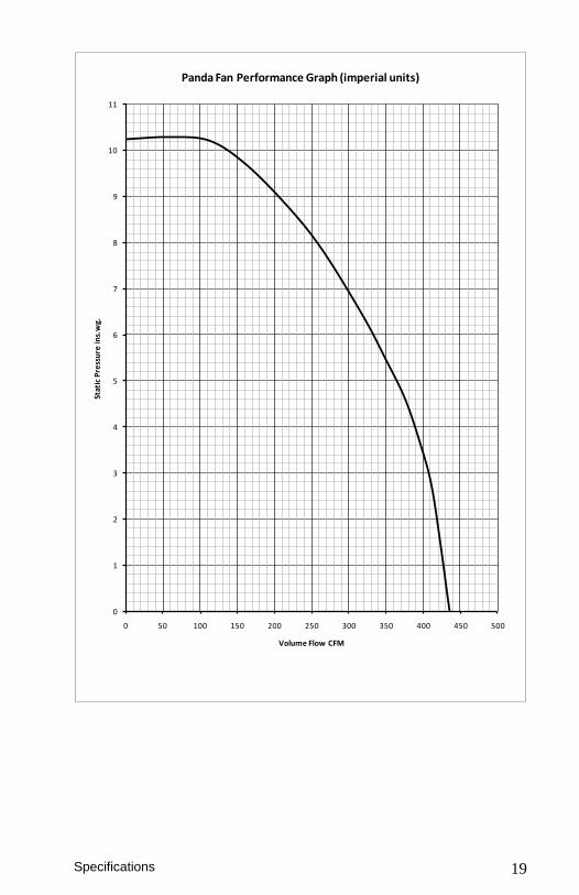
0
1
2
3
4
5
6
7
8
9
10
11
0 50 100 150 200 250 300 350 400 450 500
Stat
ic P
ress
ure
ins.
wg.
Volume Flow CFM
Panda Fan Performance Graph (imperial units)

20 Appendix A
(This page intentionally left blank)
21
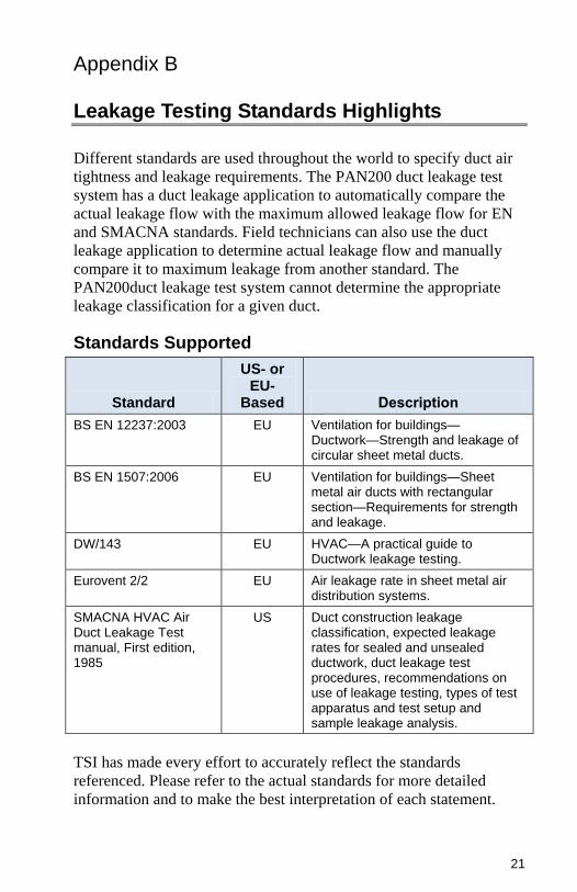
Appendix B Leakage Testing Standards Highlights
Different standards are used throughout the world to specify duct air
tightness and leakage requirements. The PAN200 duct leakage test
system has a duct leakage application to automatically compare the
actual leakage flow with the maximum allowed leakage flow for EN
and SMACNA standards. Field technicians can also use the duct
leakage application to determine actual leakage flow and manually
compare it to maximum leakage from another standard. The
PAN200duct leakage test system cannot determine the appropriate
leakage classification for a given duct.
Standards Supported
Standard
US- or EU-
Based Description
BS EN 12237:2003 EU Ventilation for buildings—Ductwork—Strength and leakage of circular sheet metal ducts.
BS EN 1507:2006 EU Ventilation for buildings—Sheet metal air ducts with rectangular section—Requirements for strength and leakage.
DW/143 EU HVAC—A practical guide to Ductwork leakage testing.
Eurovent 2/2 EU Air leakage rate in sheet metal air distribution systems.
SMACNA HVAC Air Duct Leakage Test manual, First edition, 1985
US Duct construction leakage classification, expected leakage rates for sealed and unsealed ductwork, duct leakage test procedures, recommendations on use of leakage testing, types of test apparatus and test setup and sample leakage analysis.
TSI has made every effort to accurately reflect the standards
referenced. Please refer to the actual standards for more detailed
information and to make the best interpretation of each statement.
22 Appendix B
The scope of the standards listed above includes many items other
than duct leakage. This summary, however, is limited to duct
leakage testing.
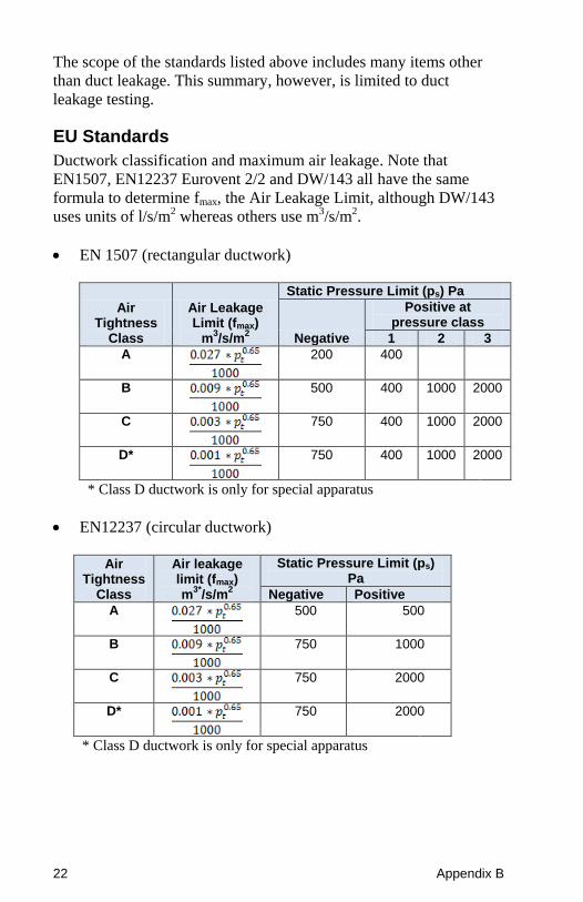
EU Standards
Ductwork classification and maximum air leakage. Note that
EN1507, EN12237 Eurovent 2/2 and DW/143 all have the same
formula to determine fmax, the Air Leakage Limit, although DW/143
uses units of l/s/m2 whereas others use m3/s/m2.
EN 1507 (rectangular ductwork)
Air Tightness
Class
Air Leakage Limit (fmax)
m3/s/m
2
Static Pressure Limit (ps) Pa
Negative
Positive at pressure class
1 2 3
A
200 400
B
500 400 1000 2000
C
750 400 1000 2000
D*
750 400 1000 2000
* Class D ductwork is only for special apparatus
EN12237 (circular ductwork)
Air
Tightness Class
Air leakage limit (fmax) m
3*/s/m
2
Static Pressure Limit (ps) Pa
Negative Positive
A
500 500
B
750 1000
C
750 2000
D*
750 2000
* Class D ductwork is only for special apparatus
Leakage Testing Standards Highlights 23
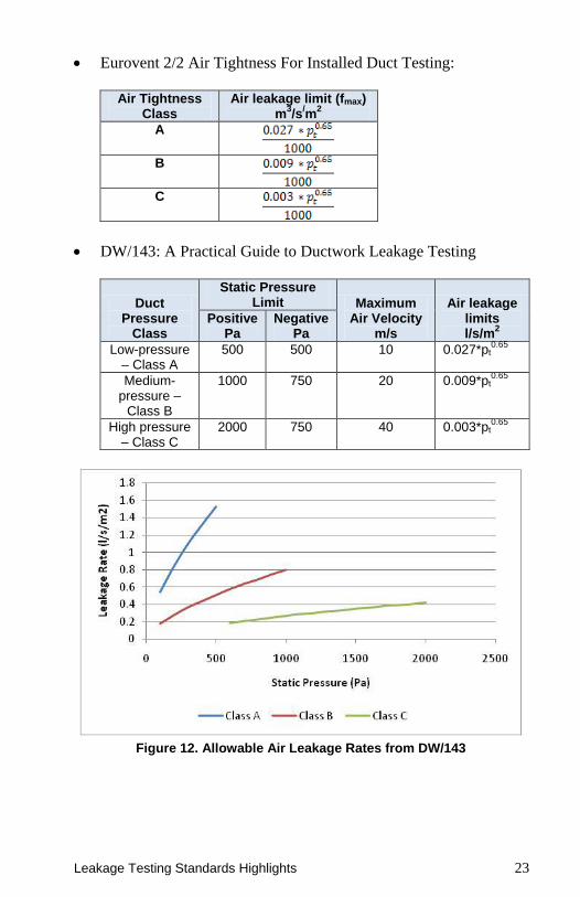
Eurovent 2/2 Air Tightness For Installed Duct Testing:
Air Tightness
Class Air leakage limit (fmax)
m3/s
/m
2
A
B
C
DW/143: A Practical Guide to Ductwork Leakage Testing
Duct Pressure
Class
Static Pressure Limit Maximum
Air Velocity m/s
Air leakage limits l/s/m
2
Positive Pa
Negative Pa
Low-pressure – Class A
500 500 10 0.027*pt0.65
Medium-pressure –
Class B
1000 750 20 0.009*pt0.65
High pressure – Class C
2000 750 40 0.003*pt0.65
Figure 12. Allowable Air Leakage Rates from DW/143
24 Appendix B
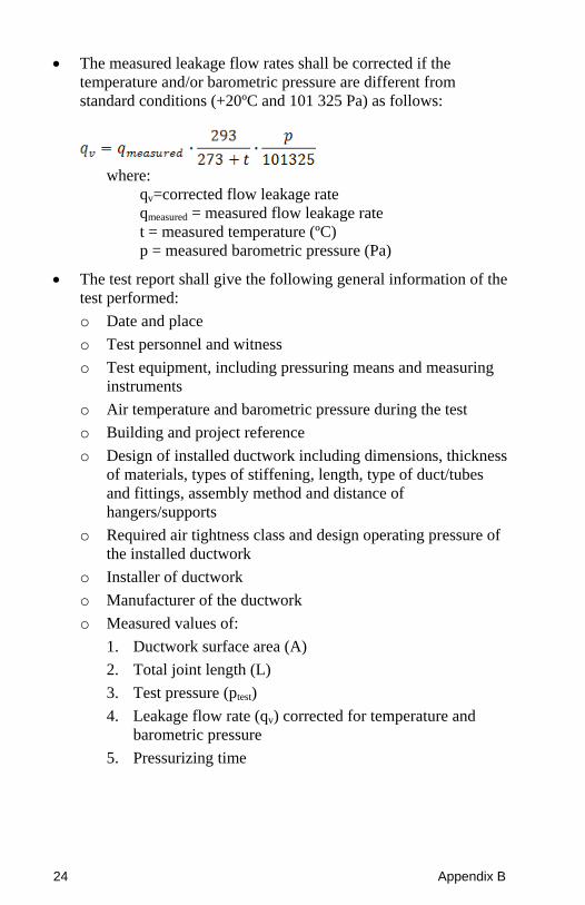
The measured leakage flow rates shall be corrected if the
temperature and/or barometric pressure are different from
standard conditions (+20ºC and 101 325 Pa) as follows:
where:
qv=corrected flow leakage rate
qmeasured = measured flow leakage rate
t = measured temperature (ºC)
p = measured barometric pressure (Pa)
The test report shall give the following general information of the
test performed:
o Date and place
o Test personnel and witness
o Test equipment, including pressuring means and measuring
instruments
o Air temperature and barometric pressure during the test
o Building and project reference
o Design of installed ductwork including dimensions, thickness
of materials, types of stiffening, length, type of duct/tubes
and fittings, assembly method and distance of
hangers/supports
o Required air tightness class and design operating pressure of
the installed ductwork
o Installer of ductwork
o Manufacturer of the ductwork
o Measured values of:
1. Ductwork surface area (A)
2. Total joint length (L)
3. Test pressure (ptest)
4. Leakage flow rate (qv) corrected for temperature and
barometric pressure
5. Pressurizing time
Leakage Testing Standards Highlights 25
o Calculated values of
1. Leakage factor (f)
2. Air leakage limit (fmax) according to the formulas given in
table above at the measured test pressure (ptest)
o Air tightness class achieved
For tests including several test pressures it is recommended to
plot the leakage factors as a function of test pressure in a diagram
together with the air leakage limit curve.
US Standards
Ductwork classification and maximum air leakage
Duct Class ½-, 1-, 2-inwg
3-inwg 4-, 6-, 10-inwg
Seal Class C B A
Sealing Applicable
Transverse Joints Only
Transverse Joints and
Seams
Joints, Seams and All Wall Penetrations
Leakage Class
Rectangular Metal
24 12 6
Round Metal
12 6 3
Maximum air leakage is then defined as
F=CLP0.65
where: F = Maximum air leakage (cfm/100 ft2)
CL = Leakage class
P = Pressure (inwg)
26 Appendix B
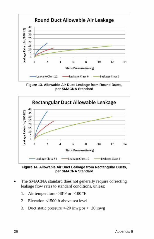
Figure 13. Allowable Air Duct Leakage from Round Ducts,
per SMACNA Standard
Figure 14. Allowable Air Duct Leakage from Rectangular Ducts,
per SMACNA Standard
The SMACNA standard does not generally require correcting
leakage flow rates to standard conditions, unless:
1. Air temperature <40ºF or >100 ºF
2. Elevation <1500 ft above sea level
3. Duct static pressure <-20 inwg or >+20 inwg
Leakage Testing Standards Highlights 27
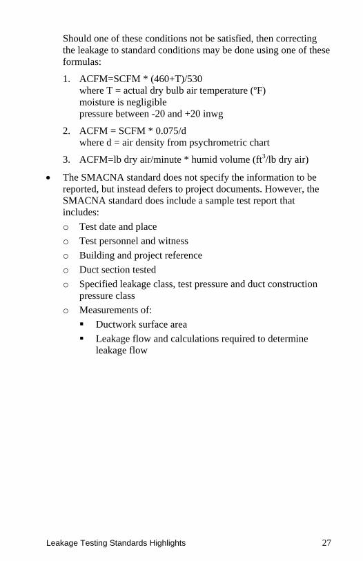
Should one of these conditions not be satisfied, then correcting
the leakage to standard conditions may be done using one of these
formulas:
1. ACFM=SCFM * (460+T)/530
where T = actual dry bulb air temperature (ºF)
moisture is negligible
pressure between -20 and +20 inwg
2. ACFM = SCFM * 0.075/d
where d = air density from psychrometric chart
3. ACFM=lb dry air/minute * humid volume (ft3/lb dry air)
The SMACNA standard does not specify the information to be
reported, but instead defers to project documents. However, the
SMACNA standard does include a sample test report that
includes:
o Test date and place
o Test personnel and witness
o Building and project reference
o Duct section tested
o Specified leakage class, test pressure and duct construction
pressure class
o Measurements of:
Ductwork surface area
Leakage flow and calculations required to determine
leakage flow

28 Appendix B
(This page intentionally left blank)
29
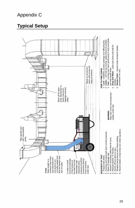
Appendix C Typical Setup

30 Appendix C
(This page intentionally left blank)
31
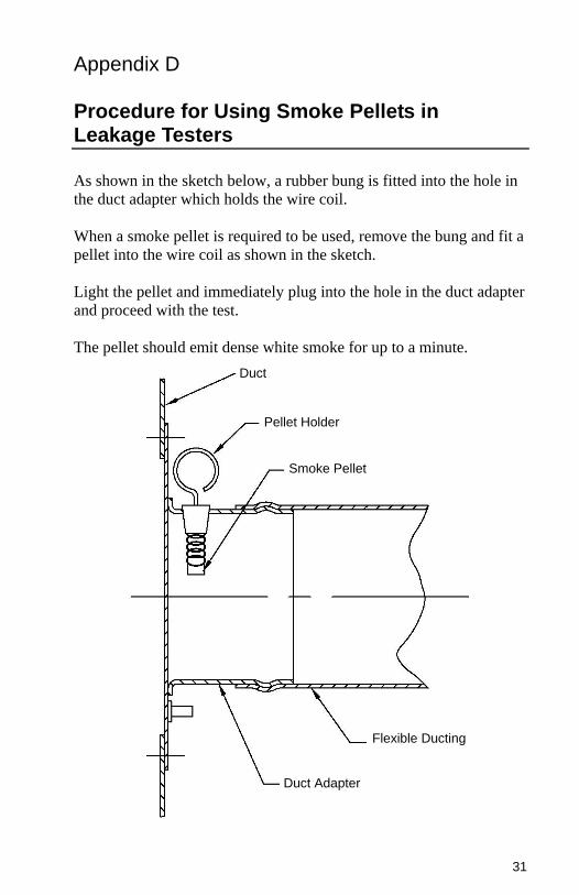
Appendix D Procedure for Using Smoke Pellets in Leakage Testers
As shown in the sketch below, a rubber bung is fitted into the hole in
the duct adapter which holds the wire coil.
When a smoke pellet is required to be used, remove the bung and fit a
pellet into the wire coil as shown in the sketch.
Light the pellet and immediately plug into the hole in the duct adapter
and proceed with the test.
The pellet should emit dense white smoke for up to a minute.
Duct
Pellet Holder
Smoke Pellet
Flexible Ducting
Duct Adapter

32 Appendix D
(This page intentionally left blank)

TSI Incorporated – 500 Cardigan Road, Shoreview, MN 55126 U.S.A
USA Tel: +1 800 874 2811 E-mail: [email protected] Website: www.tsi.com UK Tel: +44 149 4 459200 E-mail: [email protected] Website: www.tsiinc.co.uk France Tel: +33 491 11 87 64 E-mail: [email protected] Website: www.tsiinc.fr
Germany Tel: +49 241 523030 E-mail: [email protected] Website www.tsiinc.de India Tel: +91 80 41132470 E-mail: [email protected] China Tel: +86 10 8251 6588 E-mail: [email protected] Singapore Tel: +65 6595 6388 E-mail: [email protected] Contact your local TSI Distributor or visit our website www.tsi.com for more detailed specifications. P/N 6005007 Rev. A Copyright © 2012 by TSI Incorporated Printed in U.S.A