Embed Size (px)
Citation preview

CCompany
PProducts
AApplication
TTechnology
Position SensorInstruction Manual / Installation Guide
SVC-07-0001_EN-Rev03 EN 08/ 2015
EN
C P
T A
Synventive Molding Solutions Service for the Position Sensor SVC-07-0001_EN-Rev03Current version at www.synventive.com - 2 - © 2015 All rights reservedMaster Language is English Errors and omissions excepted
Table of Contents1 Service for the Position Sensor ........................................................................................31.1 Tools for the Position Sensor Service ......................................................................................... 31.2 Basic Position Sensor Information .............................................................................................. 41.3 Installing the Position Sensor ...................................................................................................... 41.4 Installing of the Actuator with Position Sensor on the Hot Runner .......................................... 61.5 Operation with SynFlow® ............................................................................................................. 61.6 Position Sensor Troubleshooting Guide ..................................................................................... 7
EN
C P
T A
Synventive Molding Solutions Service for the Position Sensor SVC-07-0001_EN-Rev03Current version at www.synventive.com - 3 - © 2015 All rights reservedMaster Language is English Errors and omissions excepted
Service and Maintenance / Tools for the Position Sensor Service
1 Service for the Position Sensor
Danger to Life by Electric ShockElectrical work must be carried out by qualified persons.For any work on the Hot Runner System, check that the system is properly grounded.For first aid contact your medical / safety representing.
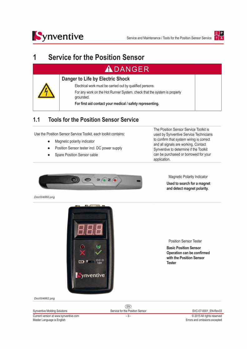
1.1 Tools for the Position Sensor Service
Use the Position Sensor Service Toolkit, each toolkit contains:
● Magnetic polarity indicator ● Position Sensor tester incl. DC power supply ● Spare Position Sensor cable
The Position Sensor Service Toolkit is used by Synventive Service Technicians to confirm that system wiring is correct and all signals are working. Contact Synventive to determine if the Toolkit can be purchased or borrowed for your application.
Doc004860.png
Magnetic Polarity IndicatorUsed to search for a magnet and detect magnet polarity.
Doc004862.png
Position Sensor TesterBasic Position Sensor Operation can be confirmed with the Position Sensor Tester
EN
C P
T A
Synventive Molding Solutions Service for the Position Sensor SVC-07-0001_EN-Rev03Current version at www.synventive.com - 4 - © 2015 All rights reservedMaster Language is English Errors and omissions excepted
Service and Maintenance / Basic Position Sensor Information
1.2 Basic Position Sensor InformationPosition Sensor - Part Number
HESASSY03 (with 3 m Cable) HESASSY05 (with 5 m Cable)
Position Sensor Temperature Rating ● Sensor: 150 °C ● Cable temperature rating: 200 °C
Position Sensor has internal temperature change compensation
1.3 Installing the Position Sensor
Danger of Material DefectsDo not pinch signal wire
NOTICEKeep surfaces in contact with the Position Sensor clean.
1) Wipe down surface where Position Sensor is to be attached
Doc004845.png
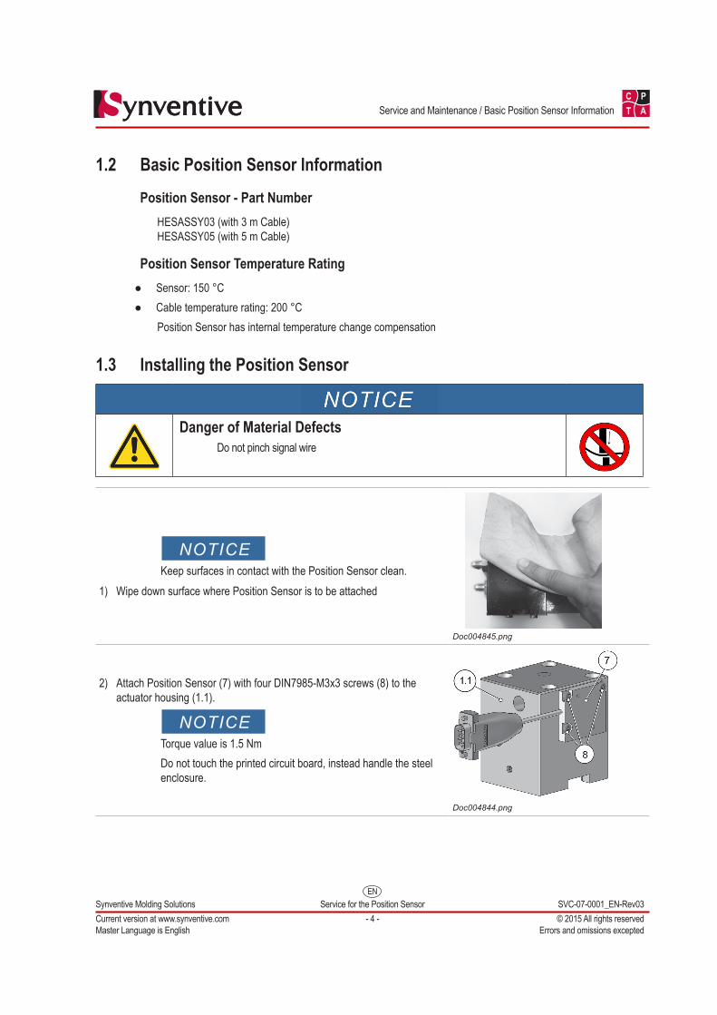
2) Attach Position Sensor (7) with four DIN7985-M3x3 screws (8) to the actuator housing (1.1).
NOTICETorque value is 1.5 NmDo not touch the printed circuit board, instead handle the steel enclosure.
Doc004844.png
EN
C P
T A
Synventive Molding Solutions Service for the Position Sensor SVC-07-0001_EN-Rev03Current version at www.synventive.com - 5 - © 2015 All rights reservedMaster Language is English Errors and omissions excepted
Service and Maintenance / Installing the Position Sensor
Doc004878.png
NOTICEEnsure the sensor does not protrude past the face of the actuator.
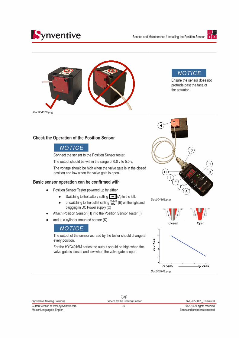
Check the Operation of the Position Sensor
NOTICEConnect the sensor to the Position Sensor tester.The output should be within the range of 0.0 v to 5.0 v.The voltage should be high when the valve gate is in the closed position and low when the valve gate is open.
Basic sensor operation can be confirmed with ● Position Sensor Tester powered up by either
● Switching to the battery setting (A) to the left. ● or switching to the outlet setting (B) on the right and
plugging in DC Power supply (C) ● Attach Position Sensor (H) into the Position Sensor Tester (I). ● and to a cylinder mounted sensor (K)
NOTICEThe output of the sensor as read by the tester should change at every position.For the HYC4016M series the output should be high when the valve gate is closed and low when the valve gate is open.
Doc004863.png
Doc005149.png
EN
C P
T A
Synventive Molding Solutions Service for the Position Sensor SVC-07-0001_EN-Rev03Current version at www.synventive.com - 6 - © 2015 All rights reservedMaster Language is English Errors and omissions excepted
Service and Maintenance / Installing of the Actuator with Position Sensor on the Hot Runner
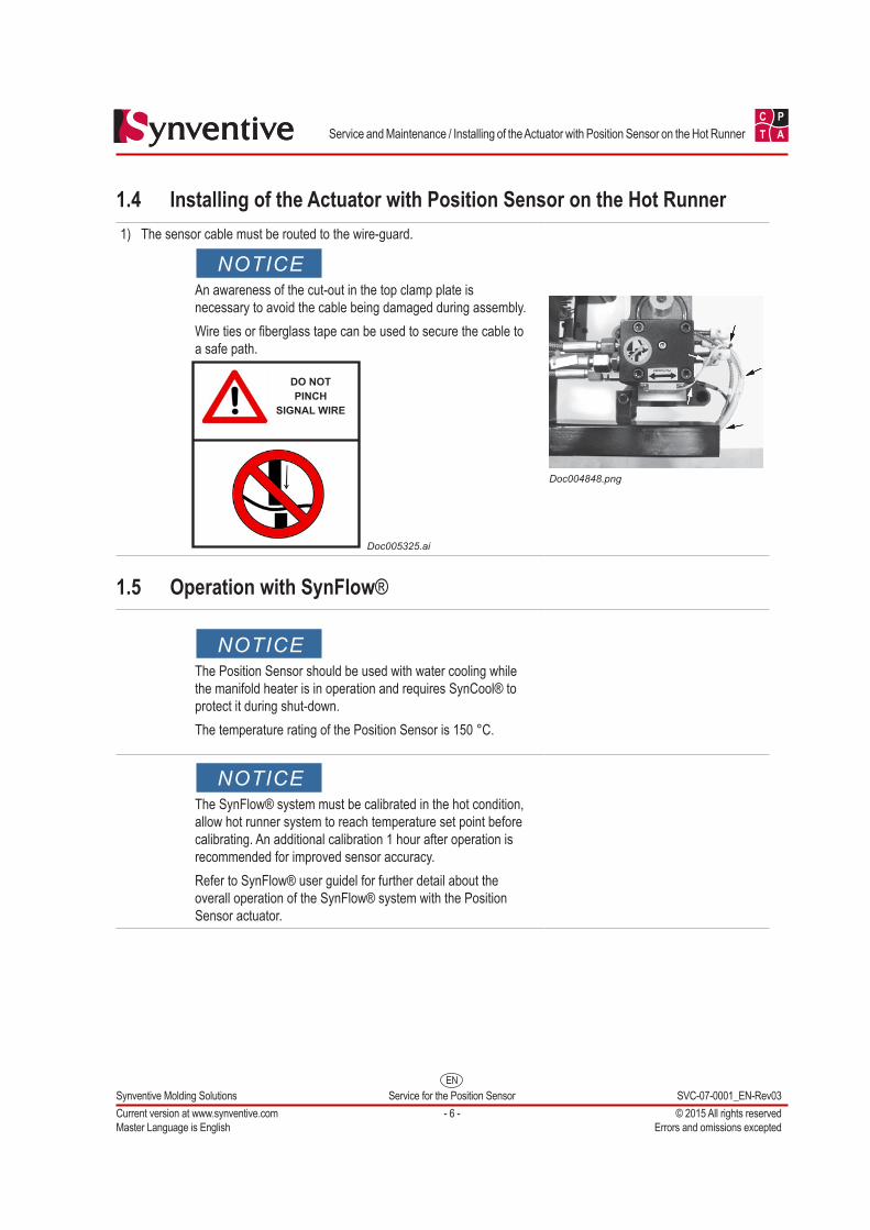
1.4 Installing of the Actuator with Position Sensor on the Hot Runner1) The sensor cable must be routed to the wire-guard.
NOTICEAn awareness of the cut-out in the top clamp plate is necessary to avoid the cable being damaged during assembly. Wire ties or fiberglass tape can be used to secure the cable to a safe path.
DO NOTPINCH
SIGNAL WIRE
Doc005325.ai
Doc004848.png
1.5 Operation with SynFlow®
NOTICEThe Position Sensor should be used with water cooling while the manifold heater is in operation and requires SynCool® to protect it during shut-down. The temperature rating of the Position Sensor is 150 °C.
NOTICEThe SynFlow® system must be calibrated in the hot condition, allow hot runner system to reach temperature set point before calibrating. An additional calibration 1 hour after operation is recommended for improved sensor accuracy.Refer to SynFlow® user guidel for further detail about the overall operation of the SynFlow® system with the Position Sensor actuator.

EN
C P
T A
Synventive Molding Solutions Service for the Position Sensor SVC-07-0001_EN-Rev03Current version at www.synventive.com - 7 - © 2015 All rights reservedMaster Language is English Errors and omissions excepted
Service and Maintenance / Position Sensor Troubleshooting Guide
1.6 Position Sensor Troubleshooting GuideUse the Position Sensor Service Toolkit, each toolkit contains a magnet probe, a Position Sensor tester and a spare Position Sensor.
1) Turn on the tester by switch to the battery setting (A) or outlet setting (B) and plugging in DC Power supply (C)
2) Connect the Position Sensor dSub (D) to the tester.3) Read the voltage on the Tester Readout (E).
4) Red LED (F) indicates a short in the sensor and should be replaced with a new sensor.
5) Green LED (G) indicates proper operation of the sensor and testing can continue.
NOTICEThe output of the sensor as read by the tester should change at every position.For the HYC4016M series the output should be high when the valve gate is closed and low when the valve gate is open.
Position Sensor Test Setup
Doc004863.png
Some Potential Issues may be:
Magnetic Polarity Indicator
Doc004860.png
1) IssueSensor output is not changing with any piston move.a) Check that sensor cable for obvious damage.b) Use magnetic polarity indicator to confirm that a magnet is present and correct magnet polarity is aimed towards the sensor assembly (North in the HYC4016M).After HES removal have the magnetic polarity indicator touch the cylinder and scan the surface facing the sensor position.
i) If magnet is incorrect or missing, replace piston with magnetized piston.ii) If magnet is present, use the spare sensor in the service toolkit to confirm bad sensor.
Use the magnetic polarity indicator to scan the surface facing the sensor position, by touching the cylinder.
Doc004861.png
HES Spare Kit
Doc004864.png
EN
C P
T A
Synventive Molding Solutions Service for the Position Sensor SVC-07-0001_EN-Rev03Current version at www.synventive.com - 8 - © 2015 All rights reservedMaster Language is English Errors and omissions excepted
Service and Maintenance / Position Sensor Troubleshooting Guide
2) IssueSensor output changes for some of the stroke but not the whole stroke. There is a “dead band.”a) Confirm the position of the sensor and that sensor is properly torqued into position.b) Cycle the actuator assembly with top clamp plate removed.
If it is still not performing, confirm with the magnetic polarity indicator that a magnet is present and correct magnet polarity (North in the HYC4016M) is aimed towards the sensor assembly.
Use the magnetic polarity indicator to scan the surface facing the sensor position, by touching the cylinder.
Doc004861.png
Doc004878.png
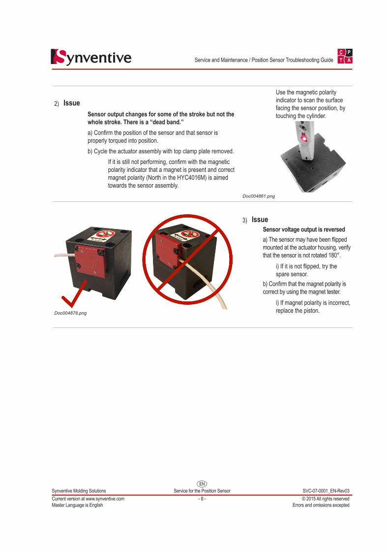
3) IssueSensor voltage output is reverseda) The sensor may have been flipped mounted at the actuator housing, verify that the sensor is not rotated 180°.
i) If it is not flipped, try the spare sensor.
b) Confirm that the magnet polarity is correct by using the magnet tester.
i) If magnet polarity is incorrect, replace the piston.

North AmericaSynventive Molding Solutions Inc.10 Centennial DrivePeabody, MA 01960Tel.: +1 978 750 8065Fax: +1 978 646 3600Email: [email protected]
EuropeSynventive Molding Solutions GmbHHeimrodstraße 10P. O. Box 312364625 BensheimTel. :+49 (0)6251 9332-0Fax :+49 (0)6251 9332-90Email: [email protected]
AsiaSynventive Molding Solutions (Suzhou) Co. Ltd.12B Gang Tian Industrial SquareSuzhou Industrial Park, China 215021Tel.: +86 512 6283 8870Fax: +86 512 6283 8890Email: [email protected]
SVC-07-0001_EN-REV02 2015-Aug-28 DTP: KA


![4 Prinsip Position Sensor [Compatibility Mode]](https://img.pdfslide.us/doc/110x75/577cd3df1a28ab9e7897aff4/4-prinsip-position-sensor-compatibility-mode.jpg)