Embed Size (px)
Citation preview

Application note
Position Control of Piezo Actuators

THIS DOCUMENT IS THE PROPERTY OF CEDRAT TECHNOLOGIES, IT MUST NOT BE COPIED OR REPRODUCED WITHOUT PRIOR WRITTEN CONSENT OF CEDRAT TECHNOLOGIES.
Application Note: Position Control of Piezo Actuators - 2/35 - AN_Position_Control_of_Piezo_Actuators_v10.docx
TABLE OF CONTENT
TABLE OF CONTENT ................................................................................................................................... 2
INTRODUCTION ........................................................................................................................................... 4
I WANT TO BE SURE TO FULLY UNDERSTAND WHAT I HAVE IN MY HANDS ......................... 5
Actuator close-up ....................................................................................................................................................... 5
Voltage amplifier close up .......................................................................................................................................... 6
Software ..................................................................................................................................................................... 6
System example ......................................................................................................................................................... 7
I JUST PLUGGED EVERYTHING. I WANT TO BE SURE THAT EVERYTHING IS CORRECT ..... 9
WHAT ARE THE KEY CRITERIA TO DEFINE A STABLE & RESPONSIVE SYSTEM? ............... 11
Step response ............................................................................................................................................................11
Rise time ....................................................................................................................................................................... 11
Overshoot ..................................................................................................................................................................... 11
Settling time .................................................................................................................................................................. 11
Steady-state error ......................................................................................................................................................... 11
Sine response or bode diagram .................................................................................................................................12
Stability margins ........................................................................................................................................................13
Gain margin .................................................................................................................................................................. 14
Phase margin ................................................................................................................................................................ 14
CAN I CHANGE THE P,I AND D PARAMETERS, AS WELL AS FILTER, AS I WANT? ............... 16
Yes, PID parameters can be changed easily ...............................................................................................................16
But NO, P-I-D should not be changed in a random way .............................................................................................16
I WANT MY ACTUATOR TO REACH THE ORDER FASTER ........................................................... 17
Simulation: Default and proposed optimized values .................................................................................................17
Initial performances ...................................................................................................................................................... 17
PID evolution ................................................................................................................................................................ 17
Interest of filtering ........................................................................................................................................................ 19
Final configuration ........................................................................................................................................................ 20
Experimentation: Default and proposed optimized values ........................................................................................21
Frequency response ...................................................................................................................................................... 21
Open loop response ...................................................................................................................................................... 22
Closed-loop response ................................................................................................................................................... 23
THIS DOCUMENT IS THE PROPERTY OF CEDRAT TECHNOLOGIES, IT MUST NOT BE COPIED OR REPRODUCED WITHOUT PRIOR WRITTEN CONSENT OF CEDRAT TECHNOLOGIES.
Application Note: Position Control of Piezo Actuators - 3/35 - AN_Position_Control_of_Piezo_Actuators_v10.docx
I WANT TO REACH A STATIC POSITION WITH A VERY FLEXIBLE SYSTEM/SOFT
STRUCTURE ................................................................................................................................................ 25
HOW CAN I BUILD A MODEL FOR PERFORMING SIMULATION?............................................... 27
System models ..........................................................................................................................................................27
The different functions ................................................................................................................................................. 27
Actuator model ............................................................................................................................................................. 27
Amplifier model ............................................................................................................................................................ 28
Sensor model ................................................................................................................................................................ 28
Controller model ........................................................................................................................................................... 29
Model parameters .....................................................................................................................................................30
Mechanical parameters ................................................................................................................................................ 30
Electrical parameters .................................................................................................................................................33

THIS DOCUMENT IS THE PROPERTY OF CEDRAT TECHNOLOGIES,
Application Note: Position Control of Piezo Actuators
INTRODUCTION
The aim of this note is to help a piezo actuator user to control its system using Cedrat
sensors and controllers.
Facing various application cases, basic rules
parameters of your system.
For advanced readers, theoretical contents
rules in positioning control of piezo actuators with a PID regulator and associated filters
In this guide, some items will allow you to quickly get information on:
Warning
For you own safety and for your system security, be sur
Good practices
This information give
Warning
Before stating, the user should read carefully the dedicated user’s manual of each part constituting
the entire control loop.
TECHNOLOGIES, IT MUST NOT BE COPIED OR REPRODUCED WITHOUT PRIOR WRITTEN CONSENT OF
- 4/35 - AN_Position_Control
piezo actuator user to control its system using Cedrat Technologies’
basic rules are given in order to stabilize and to optimize
contents are given in the last part of the document in or
rules in positioning control of piezo actuators with a PID regulator and associated filters.
In this guide, some items will allow you to quickly get information on:
For you own safety and for your system security, be sure to carefully respect
information gives you the best way to do.
Before stating, the user should read carefully the dedicated user’s manual of each part constituting
the entire control loop.
R WRITTEN CONSENT OF CEDRAT TECHNOLOGIES.
AN_Position_Control_of_Piezo_Actuators_v10.docx
Technologies’ drivers,
optimize PID based control
are given in the last part of the document in order to explain the basic
e to carefully respect that information.
Before stating, the user should read carefully the dedicated user’s manual of each part constituting

THIS DOCUMENT IS THE PROPERTY OF CEDRAT TECHNOLOGIES,
Application Note: Position Control of Piezo Actuators
I WANT TO BE SURE TO FULLY UNDERSTAND WHA
ACTUATOR CLOSE-UP
Amplified Piezo Actuators (APA®) and Parallel Prestressed Actuators (PPA) are active components
displacement proportional to a voltage
ceramics and passive parts allowing preload and amplification of piezo displacement (in case of APA®).
are also integrating Strain Gages sensors. In this application note, th
capability to be part of a closed-loop solution.
Figure
Piezo actuators are connected to supply voltage amplifier
order to allow actuators to be powered.
Figure 2 Actuators banana plugs
Warning
Completely plug bananas in order to avoid any visible metal part of the connector.
to high voltage risk.
lead to unexpected behavior of
The flex connection should
wires
TECHNOLOGIES, IT MUST NOT BE COPIED OR REPRODUCED WITHOUT PRIOR WRITTEN CONSENT OF
- 5/35 - AN_Position_Control
FULLY UNDERSTAND WHAT I HAVE IN MY HANDS
Amplified Piezo Actuators (APA®) and Parallel Prestressed Actuators (PPA) are active components
proportional to a voltage. Those actuators are composed of active parts made from piezoelectric
ceramics and passive parts allowing preload and amplification of piezo displacement (in case of APA®).
ages sensors. In this application note, this kind of actuators is
loop solution.
Figure 1 PPA20M and APA40SM actuators
supply voltage amplifier using banana plugs. Those have to be correctly plugged in
order to allow actuators to be powered.
Actuators banana plugs and Strain gage connection
Completely plug bananas in order to avoid any visible metal part of the connector.
Do not invert red and black wires when plugging in piezo actuators. This
lead to unexpected behavior of the system due to depolarization risk of piezo ceramics.
ion should not be bent with min radius of 5mm to avoid
R WRITTEN CONSENT OF CEDRAT TECHNOLOGIES.
AN_Position_Control_of_Piezo_Actuators_v10.docx
T I HAVE IN MY HANDS
Amplified Piezo Actuators (APA®) and Parallel Prestressed Actuators (PPA) are active components which will perform a
sed of active parts made from piezoelectric
ceramics and passive parts allowing preload and amplification of piezo displacement (in case of APA®). Some actuators
is considered, due to their
Those have to be correctly plugged in
Completely plug bananas in order to avoid any visible metal part of the connector. This would lead
not invert red and black wires when plugging in piezo actuators. This will
of piezo ceramics.
with min radius of 5mm to avoid disruption of printed

THIS DOCUMENT IS THE PROPERTY OF CEDRAT TECHNOLOGIES,
Application Note: Position Control of Piezo Actuators
VOLTAGE AMPLIFIER CLOSE UP
Actuators are driven and controlled using dedicated electronic
mainly composed of:
• AC-DC converter (LC75
• Voltage electronic amplifier
amplifying with x20V/V gain factor
• If actuators are equipped
the rack (SG75 for Strain gage con
• When a closed loop control
Figure 3 Typical rack with several boards
Warning
Do not plug your piezo
electrical shocks.
SOFTWARE
Closed-loop is driven by parameters that are integrated into the controller. Those parameters may be changed using a
dedicated Graphical User Interface (GUI) called HDPM45
firmware inside the controller. See your driver user manual
TECHNOLOGIES, IT MUST NOT BE COPIED OR REPRODUCED WITHOUT PRIOR WRITTEN CONSENT OF
- 6/35 - AN_Position_Control
ed using dedicated electronic boards, typically set in a rack.
(LC75 or SC75) providing stabilized voltage
electronic amplifier (LA75 or SA75) supplying appropriate voltage to
amplifying with x20V/V gain factor.
If actuators are equipped with a position sensor, sensor conditioner board
(SG75 for Strain gage conditioner or ECS75 for Eddy current conditioner
control is required, a control board is finally integrated.
Typical rack with several boards and Compact Amplifier
Do not plug your piezo actuator to the rack until your setup is completed. This
by parameters that are integrated into the controller. Those parameters may be changed using a
rface (GUI) called HDPM45 which impacts directly the essential
your driver user manual to learn how to install the GUI on your laptop
R WRITTEN CONSENT OF CEDRAT TECHNOLOGIES.
AN_Position_Control_of_Piezo_Actuators_v10.docx
ypically set in a rack. Each electronics rack is
voltage to the actuator by
board is also integrated inside
ditioner or ECS75 for Eddy current conditioner).
integrated.
and Compact Amplifier
. This will avoid any risk of
by parameters that are integrated into the controller. Those parameters may be changed using a
essential parameters of real time
on your laptop.

THIS DOCUMENT IS THE PROPERTY OF CEDRAT TECHNOLOGIES,
Application Note: Position Control of Piezo Actuators
SYSTEM EXAMPLE
In the following pages, we review several
give a practical context, we will use the example of the position control of a
gage position sensor. The next figure represents the considered actuator:
Figure 5
The actuator is driven with a LA75A amplifier coupled to a UC45 controller. Strain gage sensor is conditioned using a
SG75 board. A USB port allows the user to adjust the controller parameters with its own computer through the GUI
“HDPM45”. Those components are gathered in a signal rack (
The strain gage sensor converts strain on piezo ceramics into
loop works with voltage and the supervisor
actuator.
Amplified Piezo Actuator
APA®
TECHNOLOGIES, IT MUST NOT BE COPIED OR REPRODUCED WITHOUT PRIOR WRITTEN CONSENT OF
- 7/35 - AN_Position_Control
Figure 4 HDPM45 GUI main window
several situations that you may encounter with our closed loop system. In order to
we will use the example of the position control of an APA600M piezo
gage position sensor. The next figure represents the considered actuator:
Considered actuator equipped with strain gages
The actuator is driven with a LA75A amplifier coupled to a UC45 controller. Strain gage sensor is conditioned using a
t allows the user to adjust the controller parameters with its own computer through the GUI
. Those components are gathered in a signal rack (Figure 3).
strain gage sensor converts strain on piezo ceramics into voltage with sensitivity in µm/V. In this case, the closed
loop works with voltage and the supervisor/controller will compare these voltages to control the position of the
Strain gage connectorAmplified Piezo Actuator
R WRITTEN CONSENT OF CEDRAT TECHNOLOGIES.
AN_Position_Control_of_Piezo_Actuators_v10.docx
with our closed loop system. In order to
piezo actuator with a strain
The actuator is driven with a LA75A amplifier coupled to a UC45 controller. Strain gage sensor is conditioned using a
t allows the user to adjust the controller parameters with its own computer through the GUI
voltage with sensitivity in µm/V. In this case, the closed
to control the position of the
Strain gage connector

THIS DOCUMENT IS THE PROPERTY OF CEDRAT TECHNOLOGIES, IT MUST NOT BE COPIED OR REPRODUCED WITHOUT PRIOR WRITTEN CONSENT OF CEDRAT TECHNOLOGIES.
Application Note: Position Control of Piezo Actuators - 8/35 - AN_Position_Control_of_Piezo_Actuators_v10.docx
Figure 6 Closed loop components schematics
Sensor
Order X
Controller Amplifier
Actuator
Position

THIS DOCUMENT IS THE PROPERTY OF CEDRAT TECHNOLOGIES,
Application Note: Position Control of Piezo Actuators
I JUST PLUGGED EVERYTHING. I WANT TO BE SU
You strictly followed the instruction manual that has been provided and want to be sure that the results you are
obtaining are correct? Please follow the
PID controller parameters of UC45 are set t
very large set of installations. They provide a safe configuration, with low sp
values are pre-programmed. These parameters are not optimized for your application and you will have to tune each
and every to answer to your requirement (accuracy, settling time, bandwidth…).
P=0.05
I=200;
D=0
Filter= Lowpass@100Hz
Following graph presents the actuator response to a step
in red curve, showing oscillating response, relat
response. It highlights slower but smooth
response, you may consider that the current
are correct.
Figure 7 System typical response in Open and Closed
Good practices
Please use low level signals (<0.5Vpp before amplifier) for first tests in order to avoid any damage
if setting is not correct.
(see next Figure 8)
In order to be sure that the correct parameters are implemented
TECHNOLOGIES, IT MUST NOT BE COPIED OR REPRODUCED WITHOUT PRIOR WRITTEN CONSENT OF
- 9/35 - AN_Position_Control
ING. I WANT TO BE SURE THAT EVERYTHING IS CORRECT
You strictly followed the instruction manual that has been provided and want to be sure that the results you are
the next steps to get your answer.
er parameters of UC45 are set to default values. Those parameters are made to give stable results for a
They provide a safe configuration, with low speed but high stability margins.
These parameters are not optimized for your application and you will have to tune each
and every to answer to your requirement (accuracy, settling time, bandwidth…).
ter= Lowpass@100Hz
Following graph presents the actuator response to a step through the integrated sensor. Open loop response is visible
in red curve, showing oscillating response, related to the main structure mode. Green curve is the closed
smoother and more stable response. Therefore, if you encounter this kind of
response, you may consider that the current control setting configuration and the implementa
System typical response in Open and Closed-loop
Please use low level signals (<0.5Vpp before amplifier) for first tests in order to avoid any damage
correct. You could also limit the output voltage with two parameters in the GUI
In order to be sure that the correct parameters are implemented into the controller, you have to
R WRITTEN CONSENT OF CEDRAT TECHNOLOGIES.
AN_Position_Control_of_Piezo_Actuators_v10.docx
S CORRECT
You strictly followed the instruction manual that has been provided and want to be sure that the results you are
default values. Those parameters are made to give stable results for a
eed but high stability margins. Following
These parameters are not optimized for your application and you will have to tune each
. Open loop response is visible
main structure mode. Green curve is the closed-loop
Therefore, if you encounter this kind of
and the implementation of each function
Please use low level signals (<0.5Vpp before amplifier) for first tests in order to avoid any damage
You could also limit the output voltage with two parameters in the GUI
have to use the GUI.
THIS DOCUMENT IS THE PROPERTY OF CEDRAT TECHNOLOGIES,
Application Note: Position Control of Piezo Actuators
Figure
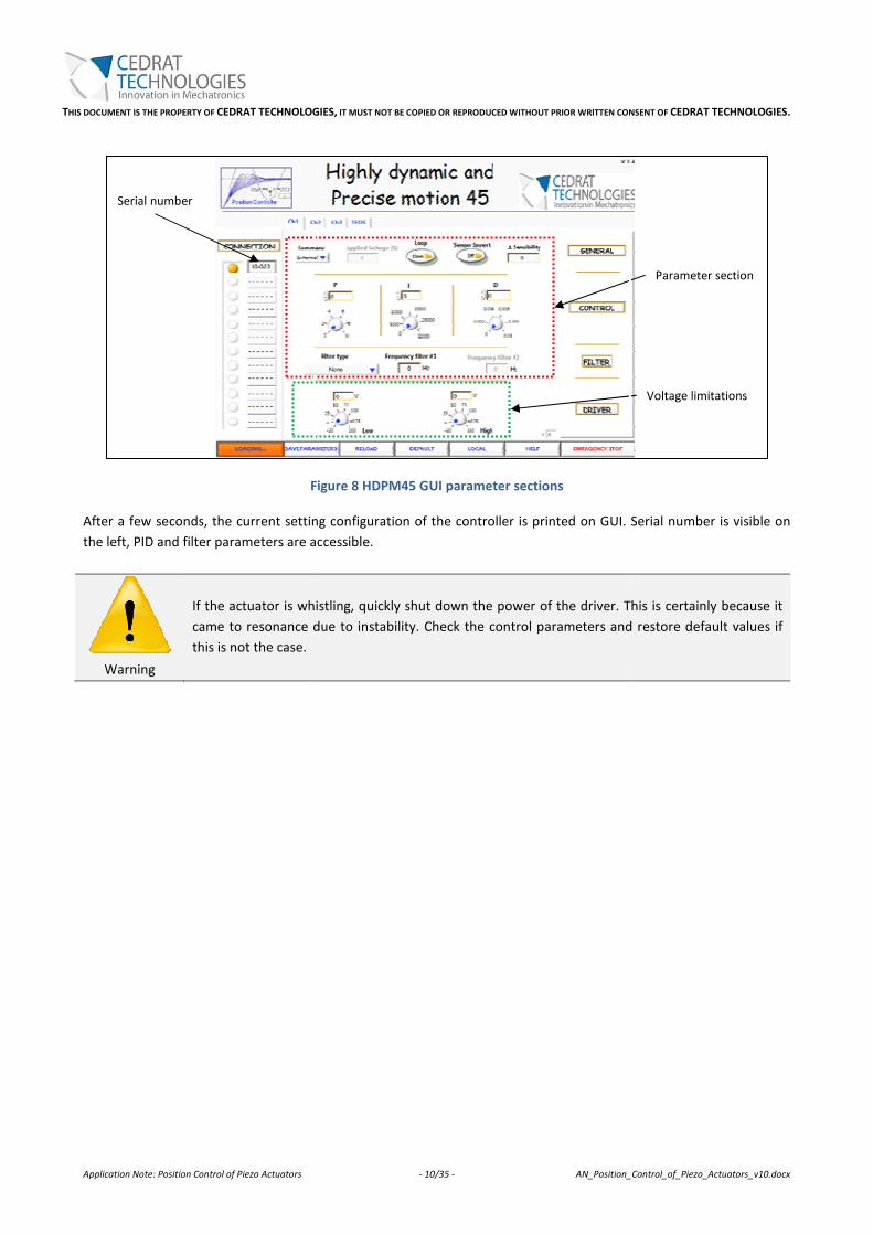
After a few seconds, the current setting
the left, PID and filter parameters are accessible.
Warning
If the actuator is whistling, quickly shut down the power
came to resonance due to instability. Check the control parameters and restore default values if
this is not the case.
Serial number
TECHNOLOGIES, IT MUST NOT BE COPIED OR REPRODUCED WITHOUT PRIOR WRITTEN CONSENT OF
- 10/35 - AN_Position_Control
Figure 8 HDPM45 GUI parameter sections
setting configuration of the controller is printed on GUI. Serial number is visible on
are accessible.
If the actuator is whistling, quickly shut down the power of the driver. This is certainly because it
came to resonance due to instability. Check the control parameters and restore default values if
R WRITTEN CONSENT OF CEDRAT TECHNOLOGIES.
AN_Position_Control_of_Piezo_Actuators_v10.docx
configuration of the controller is printed on GUI. Serial number is visible on
. This is certainly because it
came to resonance due to instability. Check the control parameters and restore default values if
Parameter section
Voltage limitations

THIS DOCUMENT IS THE PROPERTY OF CEDRAT TECHNOLOGIES, IT MUST NOT BE COPIED OR REPRODUCED WITHOUT PRIOR WRITTEN CONSENT OF CEDRAT TECHNOLOGIES.
Application Note: Position Control of Piezo Actuators - 11/35 - AN_Position_Control_of_Piezo_Actuators_v10.docx
WHAT ARE THE KEY CRITERIA TO DEFINE A STABLE & RESPONSIVE SYSTEM?
Every closed-loop system is defined by several criteria like stability and speed (bandwidth). Those criteria shall be
studied to optimize the performances of the system in control loop.
STEP RESPONSE
The step response is one of the most interesting tests in term of control characterization. Indeed, rise time, overshoot,
settling time and steady-state error can be measured.
Each of those characteristics is explained on following graphs on Figure 9 and Figure 10.
RISE TIME
Rise time refers to the time required for a signal to typically change from 10% to 90% of the step order value. There is
often a trade off to make between “Rise Time” and “Settling Time” during the calibration of a closed loop.
OVERSHOOT
Overshoot is the maximum value reached above the desired target. Reduction of this overshoot may be a strong
objective on several specifications due to mechanical hard stops, or other physical limits.
SETTLING TIME
Settling time is the time elapsed from the application of an ideal instantaneous step input to the time at which the
output has entered and remained within a specified error band. Typically, 100%+/-5% is considered. On Figure 10, it
can be seen that settling time is the same for both configurations.
STEADY-STATE ERROR
This is the difference between the desired final output and the actual one when the system reaches a steady state.
One of the most common aims of closed-loop control is to make this error null.
THIS DOCUMENT IS THE PROPERTY OF CEDRAT TECHNOLOGIES, IT MUST NOT BE COPIED OR REPRODUCED WITHOUT PRIOR WRITTEN CONSENT OF CEDRAT TECHNOLOGIES.
Application Note: Position Control of Piezo Actuators - 12/35 - AN_Position_Control_of_Piezo_Actuators_v10.docx
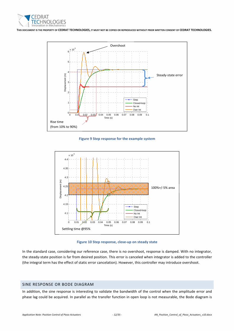
Figure 9 Step response for the example system
Figure 10 Step response, close-up on steady state
In the standard case, considering our reference case, there is no overshoot, response is damped. With no integrator,
the steady-state position is far from desired position. This error is canceled when integrator is added to the controller
(the integral term has the effect of static error cancelation). However, this controller may introduce overshoot.
SINE RESPONSE OR BODE DIAGRAM
In addition, the sine response is interesting to validate the bandwidth of the control when the amplitude error and
phase lag could be acquired. In parallel as the transfer function in open loop is not measurable, the Bode diagram is
0 0.01 0.02 0.03 0.04 0.05 0.06 0.07 0.08 0.09 0.1
4.1
4.15
4.2
4.25
4.3
4.35
4.4
x 10-5
Time (s)
Dis
plac
emen
t (m
)
Step
Closed-loopNo Int
Over Int
100%+/-5% area
Settling time @95%
0 0.01 0.02 0.03 0.04 0.05 0.06 0.07 0.08 0.09 0.10
1
2
3
4
5
6x 10
-5
Time (s)
Dis
plac
emen
t (m
)
Step
Closed-loopNo Int
Over Int
Overshoot
Rise time
(from 10% to 90%)
Steady-state error
THIS DOCUMENT IS THE PROPERTY OF CEDRAT TECHNOLOGIES, IT MUST NOT BE COPIED OR REPRODUCED WITHOUT PRIOR WRITTEN CONSENT OF CEDRAT TECHNOLOGIES.
Application Note: Position Control of Piezo Actuators - 13/35 - AN_Position_Control_of_Piezo_Actuators_v10.docx
able to give information in regards of the stability of the loop. These measurements demand more complex
instrumentation to trace a Bode diagram between sensor output and order.
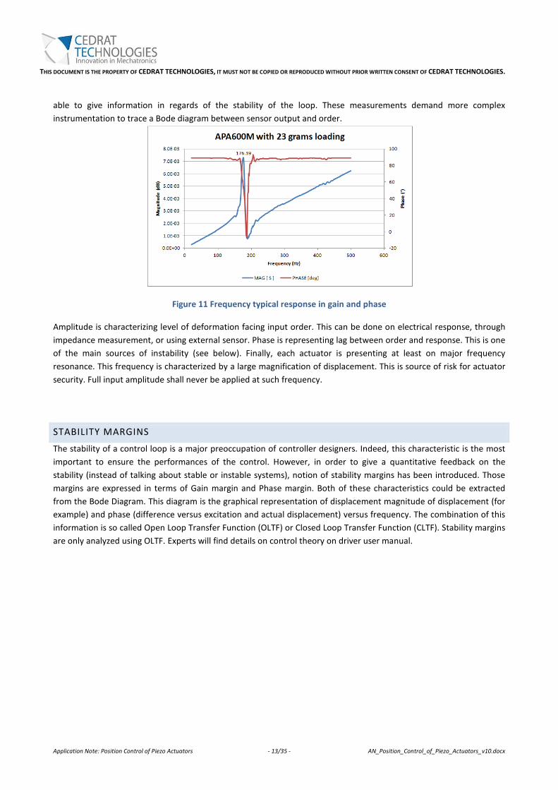
Figure 11 Frequency typical response in gain and phase
Amplitude is characterizing level of deformation facing input order. This can be done on electrical response, through
impedance measurement, or using external sensor. Phase is representing lag between order and response. This is one
of the main sources of instability (see below). Finally, each actuator is presenting at least on major frequency
resonance. This frequency is characterized by a large magnification of displacement. This is source of risk for actuator
security. Full input amplitude shall never be applied at such frequency.
STABILITY MARGINS
The stability of a control loop is a major preoccupation of controller designers. Indeed, this characteristic is the most
important to ensure the performances of the control. However, in order to give a quantitative feedback on the
stability (instead of talking about stable or instable systems), notion of stability margins has been introduced. Those
margins are expressed in terms of Gain margin and Phase margin. Both of these characteristics could be extracted
from the Bode Diagram. This diagram is the graphical representation of displacement magnitude of displacement (for
example) and phase (difference versus excitation and actual displacement) versus frequency. The combination of this
information is so called Open Loop Transfer Function (OLTF) or Closed Loop Transfer Function (CLTF). Stability margins
are only analyzed using OLTF. Experts will find details on control theory on driver user manual.
THIS DOCUMENT IS THE PROPERTY OF CEDRAT TECHNOLOGIES, IT MUST NOT BE COPIED OR REPRODUCED WITHOUT PRIOR WRITTEN CONSENT OF CEDRAT TECHNOLOGIES.
Application Note: Position Control of Piezo Actuators - 14/35 - AN_Position_Control_of_Piezo_Actuators_v10.docx
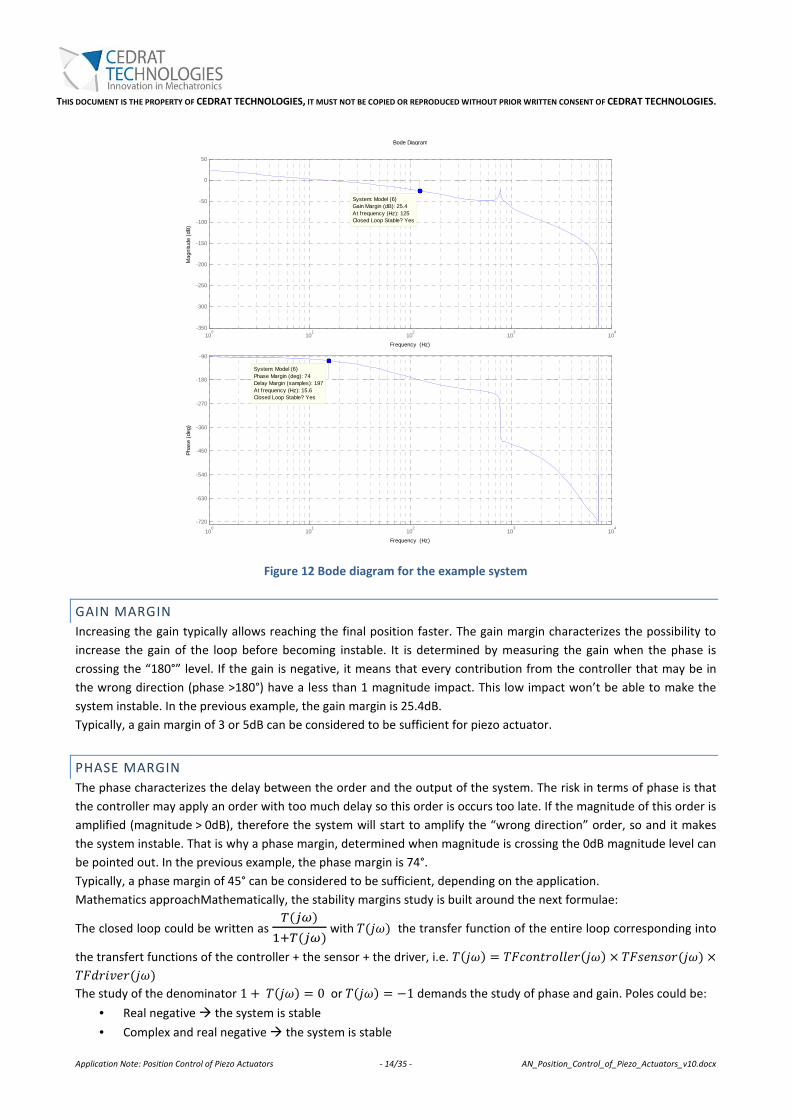
Figure 12 Bode diagram for the example system
GAIN MARGIN
Increasing the gain typically allows reaching the final position faster. The gain margin characterizes the possibility to
increase the gain of the loop before becoming instable. It is determined by measuring the gain when the phase is
crossing the “180°” level. If the gain is negative, it means that every contribution from the controller that may be in
the wrong direction (phase >180°) have a less than 1 magnitude impact. This low impact won’t be able to make the
system instable. In the previous example, the gain margin is 25.4dB.
Typically, a gain margin of 3 or 5dB can be considered to be sufficient for piezo actuator.
PHASE MARGIN
The phase characterizes the delay between the order and the output of the system. The risk in terms of phase is that
the controller may apply an order with too much delay so this order is occurs too late. If the magnitude of this order is
amplified (magnitude > 0dB), therefore the system will start to amplify the “wrong direction” order, so and it makes
the system instable. That is why a phase margin, determined when magnitude is crossing the 0dB magnitude level can
be pointed out. In the previous example, the phase margin is 74°.
Typically, a phase margin of 45° can be considered to be sufficient, depending on the application.
Mathematics approachMathematically, the stability margins study is built around the next formulae:
The closed loop could be written as �(��)
���(��) with(�) the transfer function of the entire loop corresponding into
the transfert functions of the controller + the sensor + the driver, i.e. (�) = ����������(�) × ������(�) ×
������(�)
The study of the denominator 1 + (�) = 0 or (�) = −1 demands the study of phase and gain. Poles could be:
• Real negative � the system is stable
• Complex and real negative � the system is stable
Bode Diagram
Frequency (Hz)
100
101
102
103
104
-350
-300
-250
-200
-150
-100
-50
0
50
Mag
nitu
de (
dB)
System: Model (6)Gain Margin (dB): 25.4At frequency (Hz): 125Closed Loop Stable? Yes
Frequency (Hz)
100
101
102
103
104
-720
-630
-540
-450
-360
-270
-180
-90
Pha
se (
deg)
System: Model (6)Phase Margin (deg): 74Delay Margin (samples): 197At frequency (Hz): 15.6Closed Loop Stable? Yes

THIS DOCUMENT IS THE PROPERTY OF CEDRAT TECHNOLOGIES, IT MUST NOT BE COPIED OR REPRODUCED WITHOUT PRIOR WRITTEN CONSENT OF CEDRAT TECHNOLOGIES.
Application Note: Position Control of Piezo Actuators - 15/35 - AN_Position_Control_of_Piezo_Actuators_v10.docx
• Imaginary complex � the system is unstable
This study could be analytically complex and plot diagrams are used to facilitate the analysis coupled with specific
software. The engineers should analyze the impact of the controller in term of stability.
THIS DOCUMENT IS THE PROPERTY OF CEDRAT TECHNOLOGIES,
Application Note: Position Control of Piezo Actuators
CAN I CHANGE THE P,I AND D PARAMETERS
Before going into the details, let’s explain why CTEC proposes a PID
controller is the most popular controller in the world. This is an easy real time controller with the possibility to adjust
the different parameters in real time
parameters by the following manual tuning
In the other hand, this is not the best in term of performance and other laws
implemented without the same versatility.
Coming back to the question, the answer
YES, PID PARAMETERS CAN BE CHANGED
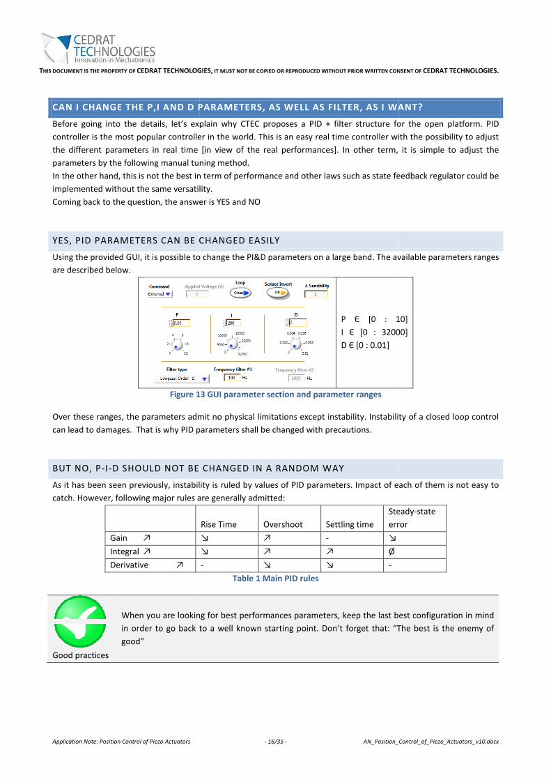
Using the provided GUI, it is possible to change the PI&D parameters on a large band. The available parameters ranges
are described below.
Figure 13
Over these ranges, the parameters admit no physical limitations
can lead to damages. That is why PID param
BUT NO, P-I-D SHOULD NOT BE CHAN
As it has been seen previously, instability is ruled by values of PID parameters
catch. However, following major rules are g
Gain ↗
Integral ↗
Derivative ↗
Good practices
When you are looking for best performances parameters, keep
in order to go back to a well know
good”
TECHNOLOGIES, IT MUST NOT BE COPIED OR REPRODUCED WITHOUT PRIOR WRITTEN CONSENT OF
- 16/35 - AN_Position_Control
AND D PARAMETERS, AS WELL AS FILTER, AS I WANT?
, let’s explain why CTEC proposes a PID + filter structure for the open platform. PID
controller is the most popular controller in the world. This is an easy real time controller with the possibility to adjust
in real time [in view of the real performances]. In other term, it is simpl
manual tuning method.
In the other hand, this is not the best in term of performance and other laws such as state feedback regulator could be
implemented without the same versatility.
answer is YES and NO
CAN BE CHANGED EASILY
Using the provided GUI, it is possible to change the PI&D parameters on a large band. The available parameters ranges
P Є [0 : 10]
I Є [0 : 32000]
D Є [0 : 0.01]
13 GUI parameter section and parameter ranges
these ranges, the parameters admit no physical limitations except instability. Instability
parameters shall be changed with precautions.
D SHOULD NOT BE CHANGED IN A RANDOM WAY
As it has been seen previously, instability is ruled by values of PID parameters. Impact of each of them is not easy to
major rules are generally admitted:
Rise Time Overshoot Settling time
Steady
error
↘ ↗ - ↘
↘ ↗ ↗ Ø
- ↘ ↘ -
Table 1 Main PID rules
When you are looking for best performances parameters, keep the last best configuration in
in order to go back to a well known starting point. Don’t forget that: “The best is the enemy of
R WRITTEN CONSENT OF CEDRAT TECHNOLOGIES.
AN_Position_Control_of_Piezo_Actuators_v10.docx
AS I WANT?
+ filter structure for the open platform. PID
controller is the most popular controller in the world. This is an easy real time controller with the possibility to adjust
rm, it is simple to adjust the
as state feedback regulator could be
Using the provided GUI, it is possible to change the PI&D parameters on a large band. The available parameters ranges
[0 : 10]
[0 : 32000]
Instability of a closed loop control
. Impact of each of them is not easy to
Steady-state
error
last best configuration in mind
Don’t forget that: “The best is the enemy of

THIS DOCUMENT IS THE PROPERTY OF CEDRAT TECHNOLOGIES, IT MUST NOT BE COPIED OR REPRODUCED WITHOUT PRIOR WRITTEN CONSENT OF CEDRAT TECHNOLOGIES.
Application Note: Position Control of Piezo Actuators - 17/35 - AN_Position_Control_of_Piezo_Actuators_v10.docx
I WANT MY ACTUATOR TO REACH THE ORDER FASTER
As it has been presented, the definition of “reaching the order position” can be quantified using rise time, settling
time and steady-state error. Those characteristics can be specified over a step signal closed-loop response. In the
presented solution, adapted PID parameters and filter are presented in order to increase performances of the
solution.
The main goal of this part is to show the influence of PID parameters and filter type on performances in order to
obtain a “faster control”.
SIMULATION: DEFAULT AND PROPOSED OPTIMIZED VALUES
INITIAL PERFORMANCES
PID parameters of UC45 controller are initially set to default values. Those parameters are giving performances that
are summarized on following table.
P
I
D
Filter
0.05
200
0
Low pass 2nd
order 100Hz
Rise time (10-90%)
Settling time (@5%)
Overshoot
14.6 ms
21.8 ms
1.2%
Figure 14 Standard initial performances
This response is conservative but relatively slow and may be not sufficient if your application needs high bandwidth.
Therefore we will discuss influence of PID parameters to make it faster.
PID EVOLUTION
The PID controller is mainly ruled by Table 1. In order to accelerate the response, it is possible to:
Look for a smallest rise time: increase P & I parameter.
Look for a smallest settling time: adjust I parameter.
According to these both case, we will see impact of P and I parameters on step response.

THIS DOCUMENT IS THE PROPERTY OF CEDRAT TECHNOLOGIES, IT MUST NOT BE COPIED OR REPRODUCED WITHOUT PRIOR WRITTEN CONSENT OF CEDRAT TECHNOLOGIES.
Application Note: Position Control of Piezo Actuators - 18/35 - AN_Position_Control_of_Piezo_Actuators_v10.docx
GAIN IMPACT
When increasing the value of P gain, the rise time is reducing. This is clearly visible on Figure 15. It is visible that this
fast response does not allow reaching the final position and it takes too much time. For high P values, it is also visible
that oscillations appear. It shows that the stability margins are reduced.
Figure 15 Impact of P parameter increase
INTEGRAL GAIN IMPACT
The integral gain I has impact on rise time because it accelerates response of the controller by wanting to cancel
steady-state error. This is done to the detriment of settling time because it makes oscillations appearing. Large
overshoot is observed. This behavior is visible on Figure 16.
Figure 16 Impact of I parameter increase
Every PID configuration proposed so far have limitations facing the need in speed improvement. We see in the next
chapter the impact of filtering to improve the speed while keeping stability in the control loop.

THIS DOCUMENT IS THE PROPERTY OF CEDRAT TECHNOLOGIES, IT MUST NOT BE COPIED OR REPRODUCED WITHOUT PRIOR WRITTEN CONSENT OF CEDRAT TECHNOLOGIES.
Application Note: Position Control of Piezo Actuators - 19/35 - AN_Position_Control_of_Piezo_Actuators_v10.docx
INTEREST OF FILTERING
It has been seen that PID parameters are ruling the response speed but they also introduce energy into system modes.
Those modes are bad/negative contributors to system stability and performances. Therefore, a control strategy
consists in adding a filter to the PID controller in order to diminish the impact of modes.
The first type of filter that has been implemented so far as a default value is a 2nd
order low pass filter. This kind of
filter is able to cut high frequencies but is not very efficient when a strong and precise mode is close to working
frequencies. A solution may consist in reducing the cut-off frequency of this filter, but it would also slow down the
system response. Another solution is to use another type of filter called “notch filter”.
A Notch filter is a stop band filter dedicated to a specific frequency. Cedrat Technologies controllers are compatible
with 2nd
and 4th
order notch. Those present the advantages not to change gain and phase far from the cut-off
frequency. This leads to potential larger stability margin.
Next figure is showing system response using [P;I;D]=[0.05;100;0] parameters. It is visible that the small frequency of
low pass filter is reducing performance of the control because it makes it too slow. A 75Hz cut-off frequency allows
reaching best performances. As a complement, Notch of 2nd
order and 4th
order are presented, showing good results.
Figure 17 Impact of filter type
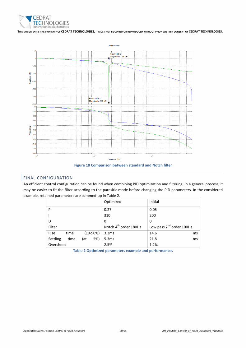
Difference in terms of Bode diagram between standard 100Hz filter and 4th
order Notch is presented on Figure 18. It is
easily seen that green curve (Notch filter) is strongly reducing magnitude of mode and increase the stability margins in
phase and gain.
THIS DOCUMENT IS THE PROPERTY OF CEDRAT TECHNOLOGIES, IT MUST NOT BE COPIED OR REPRODUCED WITHOUT PRIOR WRITTEN CONSENT OF CEDRAT TECHNOLOGIES.
Application Note: Position Control of Piezo Actuators - 20/35 - AN_Position_Control_of_Piezo_Actuators_v10.docx
Figure 18 Comparison between standard and Notch filter
FINAL CONFIGURATION
An efficient control configuration can be found when combining PID optimization and filtering. In a general process, it
may be easier to fit the filter according to the parasitic mode before changing the PID parameters. In the considered
example, retained parameters are summed-up in Table 2.
Optimized Initial
P
I
D
Filter
0.27
310
0
Notch 4th
order 180Hz
0.05
200
0
Low pass 2nd
order 100Hz
Rise time (10-90%)
Settling time (at 5%)
Overshoot
3.3ms
5.3ms
2.5%
14.6 ms
21.8 ms
1.2%
Table 2 Optimized parameters example and performances
THIS DOCUMENT IS THE PROPERTY OF CEDRAT TECHNOLOGIES, IT MUST NOT BE COPIED OR REPRODUCED WITHOUT PRIOR WRITTEN CONSENT OF CEDRAT TECHNOLOGIES.
Application Note: Position Control of Piezo Actuators - 21/35 - AN_Position_Control_of_Piezo_Actuators_v10.docx
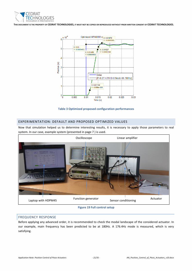
Table 3 Optimized proposed configuration performances
EXPERIMENTATION: DEFAULT AND PROPOSED OPTIMIZED VALUES
Now that simulation helped us to determine interesting results, it is necessary to apply those parameters to real
system. In our case, example system (presented in page 7 ) is used.
Figure 19 Full control setup
FREQUENCY RESPONSE
Before applying any advanced order, it is recommended to check the modal landscape of the considered actuator. In
our example, main frequency has been predicted to be at 180Hz. A 176.4Hz mode is measured, which is very
satisfying.
Laptop with HDPM45
GUI
Oscilloscope
Function generator
Linear amplifier
Actuator Sensor conditioning

THIS DOCUMENT IS THE PROPERTY OF CEDRAT TECHNOLOGIES, IT MUST NOT BE COPIED OR REPRODUCED WITHOUT PRIOR WRITTEN CONSENT OF CEDRAT TECHNOLOGIES.
Application Note: Position Control of Piezo Actuators - 22/35 - AN_Position_Control_of_Piezo_Actuators_v10.docx
Figure 20 Impact of notch filter frequency on Closed-loop transfer function
OPEN LOOP RESPONSE
System is firstly tested in open loop. This response is the very basic way to drive piezo, without any feedback about
actuator behaviour. Result is plotted below.
Figure 21 Open loop response
It can be seen that oscillations are appearing after the voltage increase. Voltage increases linearly because of driver
current limitation.
Note: Do not mix up the open loop response with the open loop analysis during the analysis of stability.
THIS DOCUMENT IS THE PROPERTY OF CEDRAT TECHNOLOGIES, IT MUST NOT BE COPIED OR REPRODUCED WITHOUT PRIOR WRITTEN CONSENT OF CEDRAT TECHNOLOGIES.
Application Note: Position Control of Piezo Actuators - 23/35 - AN_Position_Control_of_Piezo_Actuators_v10.docx
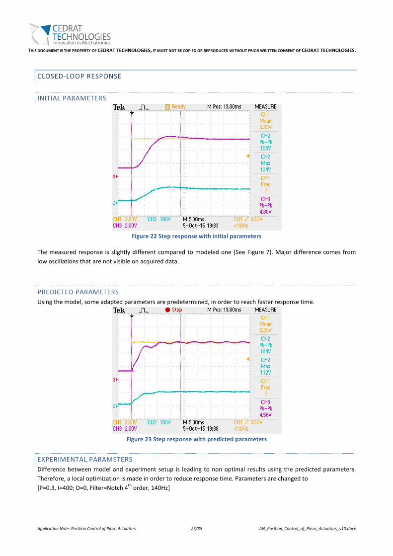
CLOSED-LOOP RESPONSE
INITIAL PARAMETERS
Figure 22 Step response with initial parameters
The measured response is slightly different compared to modeled one (See Figure 7). Major difference comes from
low oscillations that are not visible on acquired data.
PREDICTED PARAMETERS
Using the model, some adapted parameters are predetermined, in order to reach faster response time.
Figure 23 Step response with predicted parameters
EXPERIMENTAL PARAMETERS
Difference between model and experiment setup is leading to non optimal results using the predicted parameters.
Therefore, a local optimization is made in order to reduce response time. Parameters are changed to
[P=0.3, I=400; D=0, Filter=Notch 4th
order, 140Hz]
THIS DOCUMENT IS THE PROPERTY OF CEDRAT TECHNOLOGIES, IT MUST NOT BE COPIED OR REPRODUCED WITHOUT PRIOR WRITTEN CONSENT OF CEDRAT TECHNOLOGIES.
Application Note: Position Control of Piezo Actuators - 24/35 - AN_Position_Control_of_Piezo_Actuators_v10.docx
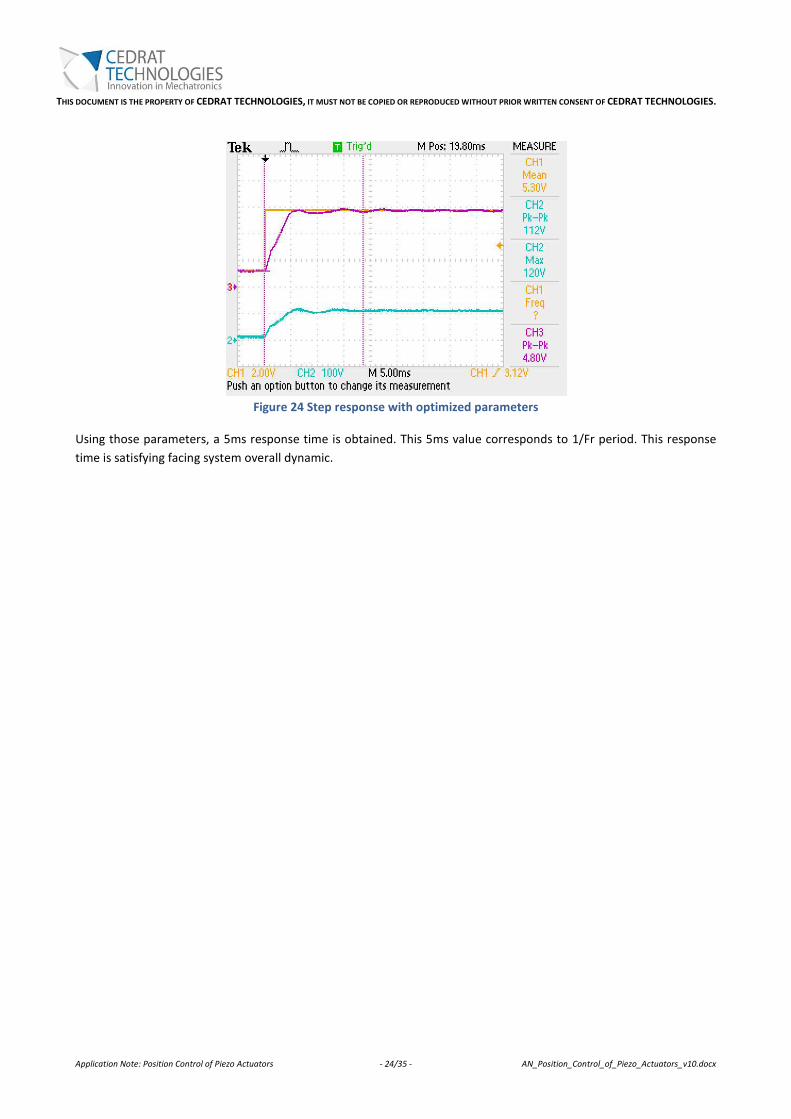
Figure 24 Step response with optimized parameters
Using those parameters, a 5ms response time is obtained. This 5ms value corresponds to 1/Fr period. This response
time is satisfying facing system overall dynamic.

THIS DOCUMENT IS THE PROPERTY OF CEDRAT TECHNOLOGIES, IT MUST NOT BE COPIED OR REPRODUCED WITHOUT PRIOR WRITTEN CONSENT OF CEDRAT TECHNOLOGIES.
Application Note: Position Control of Piezo Actuators - 25/35 - AN_Position_Control_of_Piezo_Actuators_v10.docx
I WANT TO REACH A STATIC POSITION WITH A VERY FLEXIBLE SYSTEM/SOFT STRUCTURE
In the case where high precision static positioning is the only aim of the closed-loop, a few rules may be applied to
obtain a fully satisfying behavior. Sometimes, very flexible/soft (low stiffness) structures are involved, leading to low
resonance frequencies. This is the case when large lever arms are used, for example.
Figure 25 Example of a highly amplified mechanism, with lower resonance frequency
In the standard case, with initial parameters, closed-loop may be instable if the resonance frequency is very low. In
the following example (Figure 26), a 55Hz resonance frequency system is considered. Whereas the open loop
response shows large oscillations (red curve), the actuator finally reaches its target position. On the contrary, the
closed-loop response increases with no visible limit. The controller is not able to compensate the system dynamic, it
becomes instable.
Figure 26 Low resonance frequency system responses
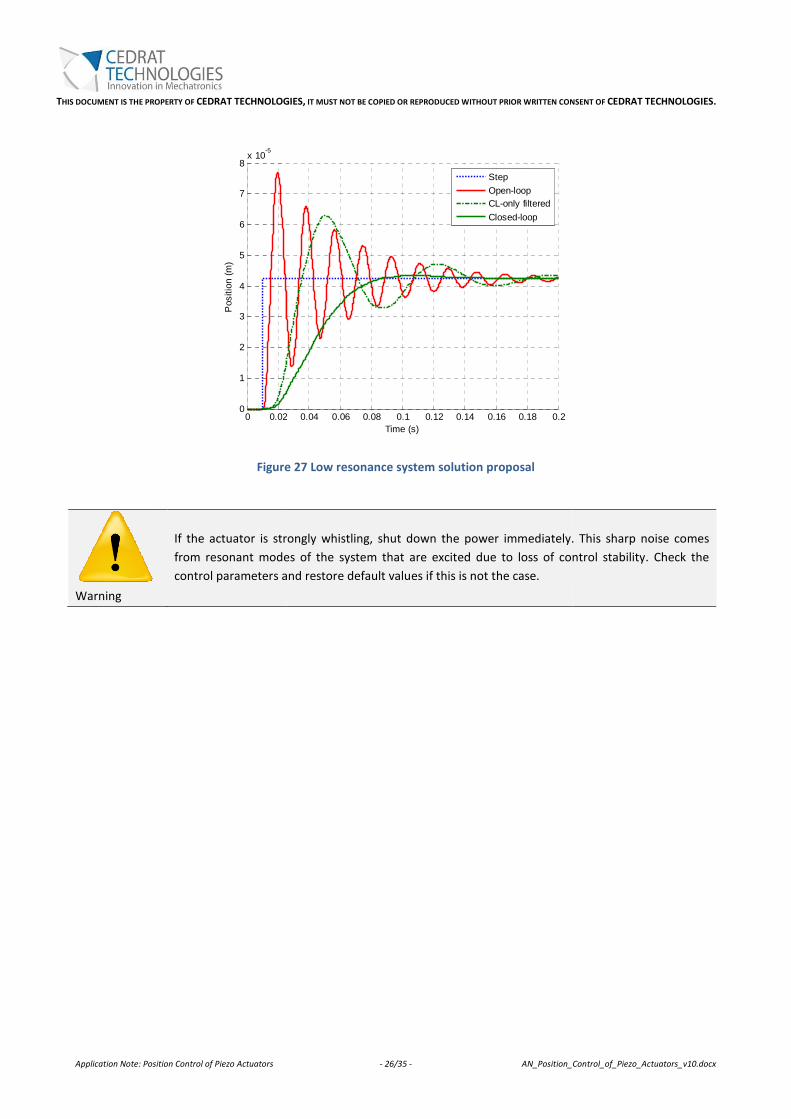
In order to restore stability, it is necessary to adapt the parameters to system characteristics. The low resonance
frequency is easily damped using a lower cut-off frequency for the low-pass filter. However, as overshoot remains, see
Figure 27, we slightly decrease the integral term of the controller (from 100 to 30). This final I adjustment leads to an
attenuation of the slope and a good fitting to the order.
0 0.02 0.04 0.06 0.08 0.1 0.12 0.14 0.16 0.18 0.2-1.5
-1
-0.5
0
0.5
1
1.5
2x 10
-4
Time (s)
Pos
ition
(m
)
Step
Std CLOpen loop
THIS DOCUMENT IS THE PROPERTY OF CEDRAT TECHNOLOGIES,
Application Note: Position Control of Piezo Actuators
Figure
Warning
If the actuator is strongly whistling, shut down the power
from resonant modes of the system that are excited due to loss of control stability
control parameters and
0 0.020
1
2
3
4
5
6
7
8x 10
-5
Pos
ition
(m
)
TECHNOLOGIES, IT MUST NOT BE COPIED OR REPRODUCED WITHOUT PRIOR WRITTEN CONSENT OF
- 26/35 - AN_Position_Control
Figure 27 Low resonance system solution proposal
If the actuator is strongly whistling, shut down the power immediately. This
from resonant modes of the system that are excited due to loss of control stability
control parameters and restore default values if this is not the case.
0.02 0.04 0.06 0.08 0.1 0.12 0.14 0.16 0.18 0.2Time (s)
Step
Open-loopCL-only filtered
Closed-loop
R WRITTEN CONSENT OF CEDRAT TECHNOLOGIES.
AN_Position_Control_of_Piezo_Actuators_v10.docx
. This sharp noise comes
from resonant modes of the system that are excited due to loss of control stability. Check the

THIS DOCUMENT IS THE PROPERTY OF CEDRAT TECHNOLOGIES, IT MUST NOT BE COPIED OR REPRODUCED WITHOUT PRIOR WRITTEN CONSENT OF CEDRAT TECHNOLOGIES.
Application Note: Position Control of Piezo Actuators - 27/35 - AN_Position_Control_of_Piezo_Actuators_v10.docx
HOW CAN I BUILD A MODEL FOR PERFORMING SIMULATION?
SYSTEM MODELS
THE DIFFERENT FUNCTIONS
The basic scheme of one channel control loop includes the following blocks (see figure 20):
• The Actuator
• The Amplifier
• The Sensor and its conditioner
• The Controller including:
o Two analogue-to-digital converters (ADC) including the anti-aliasing filters. These blocks are
characterized by sample and hold and quantization functions (the quantization is function of the
resolution of the A/D converter, typically 16bits). Those converters are used to sample the analogue
orders and feedback signals.
o A digital-to-analogue converter (DAC) with 16bits resolution to convert the digital command to an
analogue command applied on the actuator. This block is generally characterized with the maximum
range and the resolution in terms of bits.
o The regulator which computes the error between the command and the real position monitored by
the sensor. The controller is calculated to maintain a closed loop which is stable with the desired
performances (accuracy, speed,...). It includes some regulators based on analogue/digital converters
and a robust PID controller.
Figure 28 Schematic of a basic digital control loop
Each block is represented with an input and an output to model their behavior.
ACTUATOR MODEL
Before analyzing the behaviour of the loop, a first step is the definition of the model and its accuracy. In quasi-static
condition, a model of the piezo actuator with its fundamental mode can be used (see equation 1).
Sensor
Order X
Controller Amplifier
Actuator
Position

THIS DOCUMENT IS THE PROPERTY OF CEDRAT TECHNOLOGIES,
Application Note: Position Control of Piezo Actuators
( ωjH
This transfer function represents the displacement of the actuator
ceramics. This transfer function of course is linear and doesn’t take into account the creep effect or the intrinsic
hysteresis. (If necessary we suggest using simulation software to include these nonlinearities).
hysteresis is closed to 10% for piezo actuator and we assume that a linear controller is able to correct this effect
effectively. In a more accurate model, the reader could take into account this non linearity with specific model. Keep
in mind the model is representative for one behavior. Then a parametric model should be used when the environment
has an impact on the characteristics of the specified model.
Additionally, when dynamic performances or when using mechanisms are required, the actuator should be modelised
with more than its first mechanical mode. In this case, only FEM modelisation coupled with electromechanical
elements extraction could give the overall transfer function of the mechanism.
Good practices
When short settling time is required, the
accurate enough to tune the control loop due to spurious modes in the system.
recommend a modal identification
mechanism or a hardware
at higher frequency.
AMPLIFIER MODEL
In first approximation (for quasi-static application), the driver is a pure gain. You
limitation, the cut-off frequency of the
output voltage limitations.
Note: Don’t mix-up the power bandwidth with signal bandwidth. T
limitation and the max frequency sine wave could be written as
SENSOR MODEL
A sensor can be represented with a gain
Cedrat Technologies (SG75 board), this gain is defined as:
jSensor( ω
TECHNOLOGIES, IT MUST NOT BE COPIED OR REPRODUCED WITHOUT PRIOR WRITTEN CONSENT OF
- 28/35 - AN_Position_Control
)²(1)
ωω jcmjcr
Nc
V
u
mmmm
m
++==
Equation 1: Actuator Transfer Function
This transfer function represents the displacement of the actuator as a function of the applied voltage on
ceramics. This transfer function of course is linear and doesn’t take into account the creep effect or the intrinsic
hysteresis. (If necessary we suggest using simulation software to include these nonlinearities).
sed to 10% for piezo actuator and we assume that a linear controller is able to correct this effect
effectively. In a more accurate model, the reader could take into account this non linearity with specific model. Keep
or one behavior. Then a parametric model should be used when the environment
has an impact on the characteristics of the specified model.
Additionally, when dynamic performances or when using mechanisms are required, the actuator should be modelised
ore than its first mechanical mode. In this case, only FEM modelisation coupled with electromechanical
elements extraction could give the overall transfer function of the mechanism.
settling time is required, the Lumped model (based on a single mode)
to tune the control loop due to spurious modes in the system.
a modal identification / analysis from Finite Element Model software of the
mechanism or a hardware-in-the loop identification process to take into account the other modes
static application), the driver is a pure gain. You shall integrate the
off frequency of the driver when the system requires bandwidth or the non linearities like the
20)( ==In
OutjDriver ω
Equation 2 Amplifier Transfer Function
up the power bandwidth with signal bandwidth. The first one is characterized by the current
limitation and the max frequency sine wave could be written as �� =!"#$
%&&×'×(&)*+,
A sensor can be represented with a gain coupled to a first order low pass filter. If you use a
Cedrat Technologies (SG75 board), this gain is defined as:
voltageinputMaximal
strokeMaximal
In
Out
__
_) ==ω
Equation 3 Sensor Transfer Function
R WRITTEN CONSENT OF CEDRAT TECHNOLOGIES.
AN_Position_Control_of_Piezo_Actuators_v10.docx
function of the applied voltage on the
ceramics. This transfer function of course is linear and doesn’t take into account the creep effect or the intrinsic
hysteresis. (If necessary we suggest using simulation software to include these nonlinearities). In a first order the
sed to 10% for piezo actuator and we assume that a linear controller is able to correct this effect
effectively. In a more accurate model, the reader could take into account this non linearity with specific model. Keep
or one behavior. Then a parametric model should be used when the environment
Additionally, when dynamic performances or when using mechanisms are required, the actuator should be modelised
ore than its first mechanical mode. In this case, only FEM modelisation coupled with electromechanical
based on a single mode) may not be
to tune the control loop due to spurious modes in the system. We strongly
from Finite Element Model software of the
ation process to take into account the other modes
integrate the output current
or the non linearities like the
he first one is characterized by the current
. If you use a strain gages sensor from
voltage

THIS DOCUMENT IS THE PROPERTY OF CEDRAT TECHNOLOGIES, IT MUST NOT BE COPIED OR REPRODUCED WITHOUT PRIOR WRITTEN CONSENT OF CEDRAT TECHNOLOGIES.
Application Note: Position Control of Piezo Actuators - 29/35 - AN_Position_Control_of_Piezo_Actuators_v10.docx
Figure 29 Sensor model
Numerical application: For an APA120ML, the maximum stroke is 120µm and the maximum voltage order is 8.5V: The
gain is 70833 V/m
CONTROLLER MODEL
The controller includes a PID regulator in series with a dedicated filter. A filter is placed in line to limit the effect of the
resonant frequency of the actuator. If the actuator has a low quality factor or if the bandwidth is very low, this filter
can be bypassed and only an adjustment of the PID parameters will then optimize the behavior of the loop by
reducing the Integral parameter (play the role of integrator, i.e. low pass filter).
Figure 30 Controller model
A PID controller attempts to correct the error between a measured process variable and a desired set point by
calculating and then outputting a corrective action that can adjust the process accordingly.
It is used to ensure an optimum response behavior of the actuator to its order- reducing error in velocity, in
acceleration and mainly in position.
Finally, the controller is built in digital domain then discrete transfer function should be used to implement the P, I, D
bloc functions.
Effect of the P term Effect of the I term Effect of the D term
Figure 31 Controller frequency response, effect of P,I and D
1
Sensor
Gsensor
Gsensor m->V
1
Tau_sensor.s+1
Bwdth sensor
1
Position
1- no fi lter2- Lowpass3- 2nd order notch4- 4th order notch
1
command
P
P
Notch_ana_num(s)
Notch_ana_den(s)
Notch fi lter N°2
Notch_ana_num(s)
Notch_ana_den(s)
Notch fi lter N°1
Notch_num(z)
Notch_den(z)
Notch 2
Notch_num(z)
Notch_den(z)
Notch 1
Mul tiportSwitch
Filter_num(z)
Filter_den(z)
Lowpass
K Ts
z-1
I2
K Ts
z-1
I
1
Tau_DAC.s+1
Filtre DAC
1
Tau_ADC.s+1
Filtre ADC2
1
Tau_ADC.s+1
Filtre ADC1
DACK (z-1)
Ts z
D
fil ter_choice
Constant
ADC sensor
ADC order
K Ts
z-1
1
2
Sensor
1
Order
THIS DOCUMENT IS THE PROPERTY OF CEDRAT TECHNOLOGIES, IT MUST NOT BE COPIED OR REPRODUCED WITHOUT PRIOR WRITTEN CONSENT OF CEDRAT TECHNOLOGIES.
Application Note: Position Control of Piezo Actuators - 30/35 - AN_Position_Control_of_Piezo_Actuators_v10.docx
MODEL PARAMETERS
MECHANICAL PARAMETERS
System mechanical parameters can be determined using few different methods. The goal of this step is to obtain
system frequency behavior for the first mode.
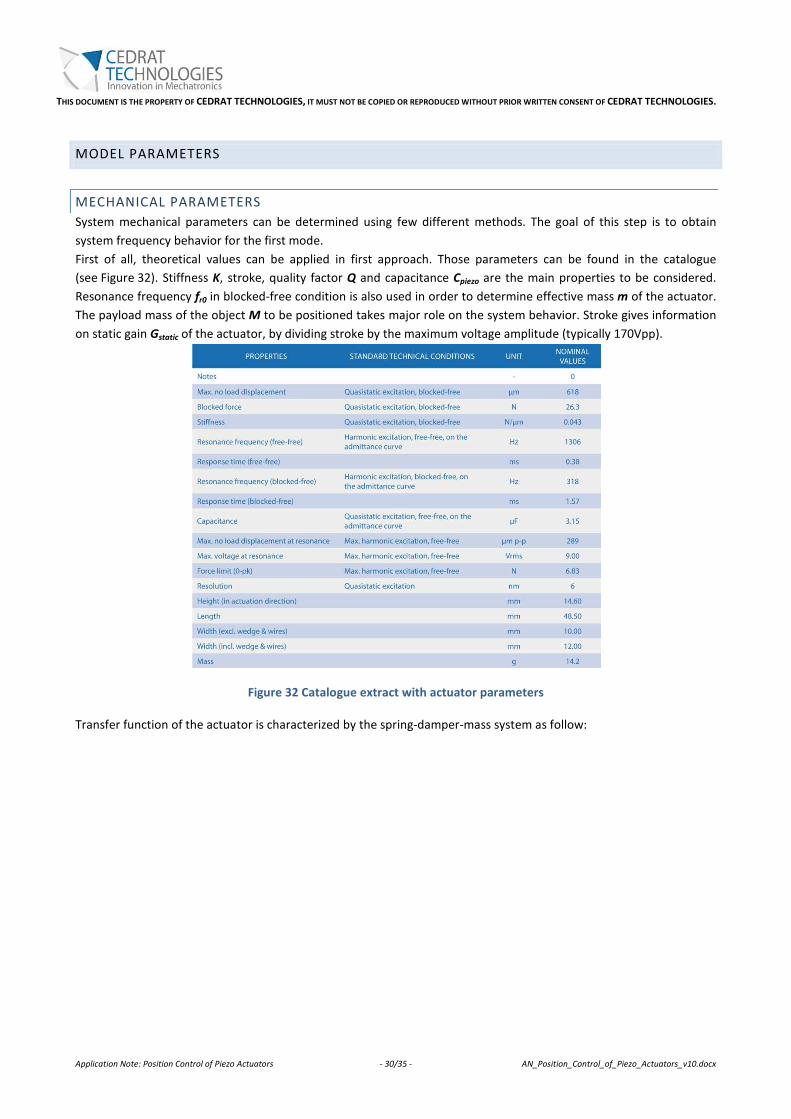
First of all, theoretical values can be applied in first approach. Those parameters can be found in the catalogue
(see Figure 32). Stiffness K, stroke, quality factor Q and capacitance Cpiezo are the main properties to be considered.
Resonance frequency fr0 in blocked-free condition is also used in order to determine effective mass m of the actuator.
The payload mass of the object M to be positioned takes major role on the system behavior. Stroke gives information
on static gain Gstatic of the actuator, by dividing stroke by the maximum voltage amplitude (typically 170Vpp).
Figure 32 Catalogue extract with actuator parameters
Transfer function of the actuator is characterized by the spring-damper-mass system as follow:

THIS DOCUMENT IS THE PROPERTY OF CEDRAT TECHNOLOGIES, IT MUST NOT BE COPIED OR REPRODUCED WITHOUT PRIOR WRITTEN CONSENT OF CEDRAT TECHNOLOGIES.
Application Note: Position Control of Piezo Actuators - 31/35 - AN_Position_Control_of_Piezo_Actuators_v10.docx
Effective mass m determination m
Kf r π2
10 =
⇔ ( )20.2 rf
Km
π=
System resonance frequency
mM
Kf r +
=π2
1
Quality factor Q= 100 arbitrary and by experience or measurements
Transfer function
1.).()(
2 ++=
ωτωτω
jQj
GjFT static
whereK
mM
f r
+==.2
1
πτ
Equation 4 Resonance frequency and transfer function
The mechanical parameters used are summed-up into following table. Those values can be generally found inside the
catalogue, or on factory verification sheet provided with your actuator.
Parameter Value Units Note
Actuator (APA600M)
Stroke 618 µm
Stiffness K 0.04349 N/µm
Resonance frequency fr0 318 kHz Blocked-free condition
Capacitance Cpiezo 3.15 µF
Quality factor Q 100 - Typical value @ low level
@ full range, the Q factor is
reduced around 30-50.
Effective mass 11.8 gr Using Equation 4
Table 4 Actuator characteristics
THIS DOCUMENT IS THE PROPERTY OF CEDRAT TECHNOLOGIES, IT MUST NOT BE COPIED OR REPRODUCED WITHOUT PRIOR WRITTEN CONSENT OF CEDRAT TECHNOLOGIES.
Application Note: Position Control of Piezo Actuators - 32/35 - AN_Position_Control_of_Piezo_Actuators_v10.docx
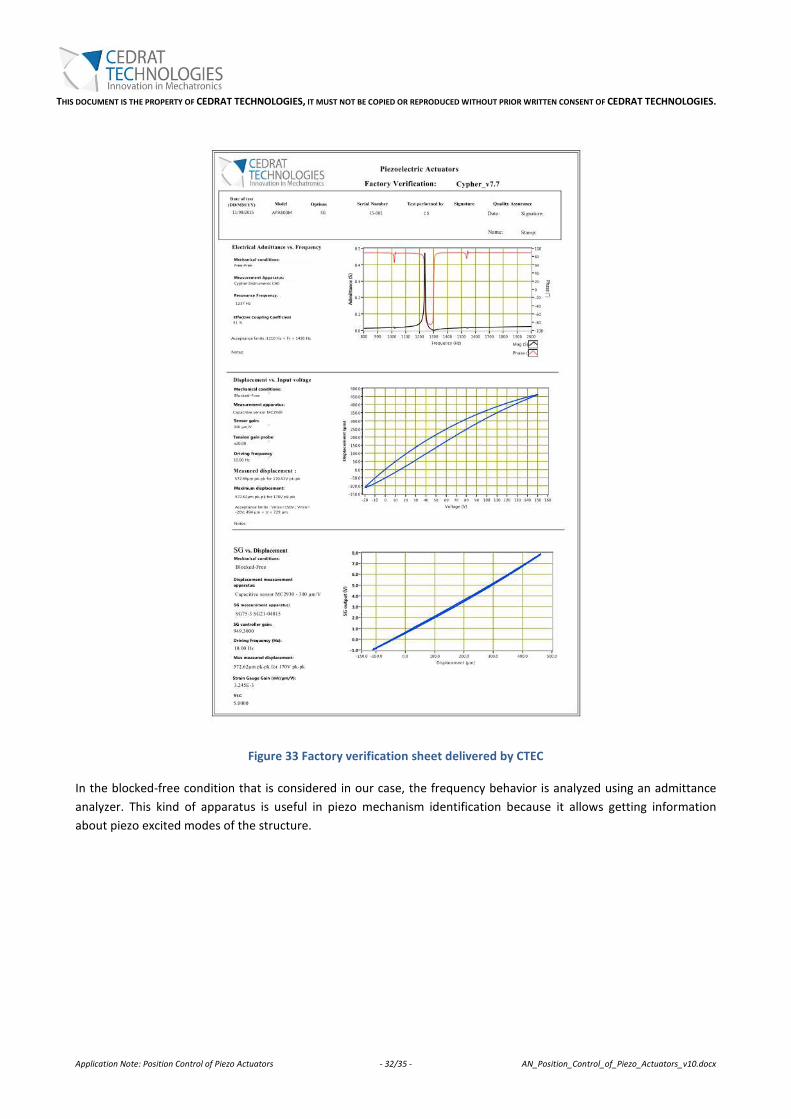
Figure 33 Factory verification sheet delivered by CTEC
In the blocked-free condition that is considered in our case, the frequency behavior is analyzed using an admittance
analyzer. This kind of apparatus is useful in piezo mechanism identification because it allows getting information
about piezo excited modes of the structure.

THIS DOCUMENT IS THE PROPERTY OF CEDRAT TECHNOLOGIES, IT MUST NOT BE COPIED OR REPRODUCED WITHOUT PRIOR WRITTEN CONSENT OF CEDRAT TECHNOLOGIES.
Application Note: Position Control of Piezo Actuators - 33/35 - AN_Position_Control_of_Piezo_Actuators_v10.docx
Figure 34 Admittance measurement on considered system
For more complex or detailed systems, the elementary model may not be enough. A modal identification from Finite
Element Model software of the mechanism or a hardware-in-the loop identification process may be necessary to take
into account other modes at higher frequencies in order to better fit the real application behaviour.
Figure 35 Modal identification on a multi degrees of freedom mechanism
ELECTRICAL PARAMETERS
Electrical parameters are decomposed into 2 categories: signal and power. Signal data concerns ADC and DAC
converters, sensor bandwidth and gain for example. Power data is about current limitations, voltage saturation. Those
parameters are mainly ruled by hardware (Typical values are given in Table 5). The control limitations induced by
these data vary from one configuration to another.

THIS DOCUMENT IS THE PROPERTY OF CEDRAT TECHNOLOGIES, IT MUST NOT BE COPIED OR REPRODUCED WITHOUT PRIOR WRITTEN CONSENT OF CEDRAT TECHNOLOGIES.
Application Note: Position Control of Piezo Actuators - 34/35 - AN_Position_Control_of_Piezo_Actuators_v10.docx
Parameter Value Units Note
Controller (UC45)
Sampling frequency
ADC filter frequency 100 kHz 1st order low pass
DAC filter frequency 5 kHz 1st order low pass
P, I, D - See §XXXX
Filter - See §XXXX
Amplifier (LA75A)
Gain 20
Cut-off frequency – small
signal
33 kHz 1st order low pass
Max voltage saturation +150 V
Min voltage saturation -20 V
Current limitation 90 mA Refer to CTEC catalogue to obtain current limitation of
various amplifiers (the power bandwidth). Example for
LA75A.
Sensor (SG75)
Gain 8.5/stroke Gain is adapted to entire deformation stroke real value
can be extracted from factory verification sheet
Cut-off frequency 15 kHz 1st order low pass
Table 5 Typical electrical parameters values

THIS DOCUMENT IS THE PROPERTY OF CEDRAT TECHNOLOGIES, IT MUST NOT BE COPIED OR REPRODUCED WITHOUT PRIOR WRITTEN CONSENT OF CEDRAT TECHNOLOGIES.
Application Note: Position Control of Piezo Actuators - 35/35 - AN_Position_Control_of_Piezo_Actuators_v10.docx