Embed Size (px)
Citation preview
FACTA UNIVERSITATISSeries: Mechanical Engineering Vol.1, No 9, 2002, pp. 1217 - 1230
POSITION CONTROL OF AN ELECTRO-HYDRAULICSERVO SYSTEM USING SLIDING MODE CONTROL
ENHANCED BY FUZZY PI CONTROLLER UDC 681.513.3
Miroslav Mihajlov1, Vlastimir Nikolić1, Dragan Antić2
1 Department of Precise Mechanical Engineering and Automatic Control, University of Niš,Faculty of Mechanical Engineering, Beogradska 14, 18000 Niš, Serbia and Montenegro
2 Department of Automatic Control, University of Niš,Faculty of Electronic Engineering, Beogradska 14, 18000 Niš, Serbia and Montenegro
Abstract. Variable structure control with sliding mode, also called sliding modecontrol, is a particularly suitable as possible control solution in electro-hydraulicsystems. In this paper, we apply the technique of the sliding mode control enhanced byfuzzy PI controller to a typical electro-hydraulic system, whose mathematical modelaccounts for the main nonlinearities including internal friction. The position controlproblem in the presence of unmodeled dynamics, parametric uncertainties and externaldisturbances was investigated. Fuzzy controller is added in the feedforward branch ofthe closed loop to improve the performance of the variable structure controller (withfixed boundary layer) with regard to the position precision and disturbance rejection.The performance improvement is demonstrated through simulation results.
1. INTRODUCTION
Electro-hydraulic systems play an indispensable role in industrial applications wherelarge inertia and torque loads have to be handled, providing a high degree of bothaccuracy and performance [12]. The dynamics of these systems are highly nonlinear andtheir models inevitable contain parametric uncertainties and unmodeled dynamics. Inrecent articles [2], [11], [18], it is demonstrated that the application of nonlinear robustcontrol techniques is a necessity for successful operation of electro-hydraulic systems.
Among these techniques, variable structure control with a sliding mode (also calledsliding mode control) have attracted considerable attention because it provides a systematicapproach to the problem of maintaining stability and consistent performance in the face ofmodelling imprecision and disturbances [5], [17]. However, the discontinuous term intraditional sliding mode control (SMC) causes an effect called chattering which is highly
Received February 04, 2003
M. MIHAJLOV, V. NIKOLIĆ, D. ANTIĆ1218
undesirable. A well known and simple solution for chattering reduction is boundary layerapproach, in which a continuos control action is used in the vicinity of the switching surface.By introducing boundary layer, chattering can be reduced, but tracking performance androbustness are compromised. There are two different approaches proposed in the literaturethat deal with the problem of tracking error reduction in the presence of boundary layer. Oneapproach is to use the variable boundary layer [8], [17]. The other approach is to use integralaction inside the fixed boundary layer [6]. On the other hand, in [16] fuzzy PD controller isadded in the feedforward branch, complementary to sliding mode controller, in order toimprove the robustness property and performance of the SMC. In the last case, the designsfor SMC and fuzzy block are mutually independent.
In this paper, we investigate the position tracking problem of an electro-hydraulicservo system applying a traditional SMC approach [17] in the first step of the controllerdesign. To improve tracking accuracy in the presence of boundary layer, fuzzy inferenceis employed. In [1], [13], we considered fuzzy tuning of sliding mode controllerparameters – the switching gain and the thickness of the boundary layer. Here, a fuzzy PIcontroller is added in the feedforward branch of the closed-loop, in parallel with the SMCwith fixed boundary layer, following the idea proposed in [16].
2. PROBLEM FORMULATION
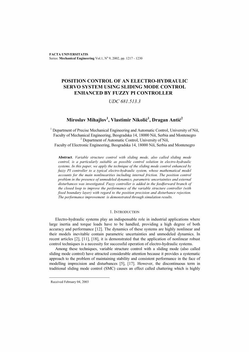
The electro-hydraulic servo system which is the object of this study is composed of adouble-ended hydraulic cylinder driven by a direct drive servo-proportional valve (Fig.1). The configuration, a part of simulation model and physical parameters of this systemwere taken from [11]. The objective is to construct a sliding mode controller with fixedboundary layer to obtain precise position control of a nonlinear electro-hydraulic servosystem.
spring
valveactuator
Fig. 1. A schematic diagram of the electro-hydraulic system [11]
In order to represent servo valve dynamics through a wider frequency range, a secondorder transfer function is used as approximation of the valve dynamics. The relationbetween the servo valve spool position xv and the input voltage u can be written as
1/2/ 22 +ωξ+ω=
vvv
vv
ssk
ux , (1)
where kv is the valve gain, ξv is the damping ratio of the servo valve and ωv is the naturalfrequency of the servo valve.
The differential equations governing the dynamics of the actuator are given in [12].
Position Control of an Electro-Hydraulic Servo System Using Sliding Mode Control ... 1219
Defining the load pressure PL as PL=P1-P2 and the load flow QL as QL=(Q1+Q2)/2, therelationship between the load pressure PL and the load flow QL for an ideal criticalservovalve with a matched and symmetric orifice can be expressed as follows:
ρ−= LvS
vdLPxPwxCQ )(sgn , (2)
where Cd represents discharge coefficient, w is the spool valve area gradient, Ps is thesupply pressure and ρ is the fluid density.
When the continuity equation is applied to the fluid flow, the following expression canbe derived:
Le
tLtpL PVPCxAQ
β++=
4, (3)
where A represents the actuator ram area, x is the actuator piston position, Ctp is the totalleakage coefficient, Vt is the total actuator volume and βe is the effective bulk modulus ofoil.
The piston force equation is given by
fL FkxxmAP ++= , (4)
where m represents mass of the piston and load, k is the spring constant and Ff is thefriction force.
The mathematical model given by the equations (1)-(4) represents a base for thesimulation model. Nonlinearities in the simulation model, besides mentioned above,include friction, servovalve rate limit, stroke limit and input current saturation.
Since the sliding mode control is robust to unmodeled dynamics a 3rd order simplermodel is obtained by combining (1)-(4) and neglecting the valve dynamics (xv=kvu):
)()()()()()()()(),(
)()(
3
13
32
21
tdtubtxtatdtubtfx
txxtxx
iii ++−=++=
==
∑=
xxx
(5)
where
.14)(
;)sgn(4
;4
;4
;4
];[][
3
2
21
321
eet
tpe
Lvsdv
t
e
t
tpe
t
e
t
etp
T
Fm
FV
Ctd
PxPwCk
mVA
b
mVC
amV
Amkak
mVC
a
xxxxxx
−β
−=
ρ−β
=
β=
β+=
β=
=
Friction in the hydraulic cylinder is taken into account as an external disturbance andthe dynamics of the servo valve is neglected.
M. MIHAJLOV, V. NIKOLIĆ, D. ANTIĆ1220
3. INTERNAL FRICTION MODELLING
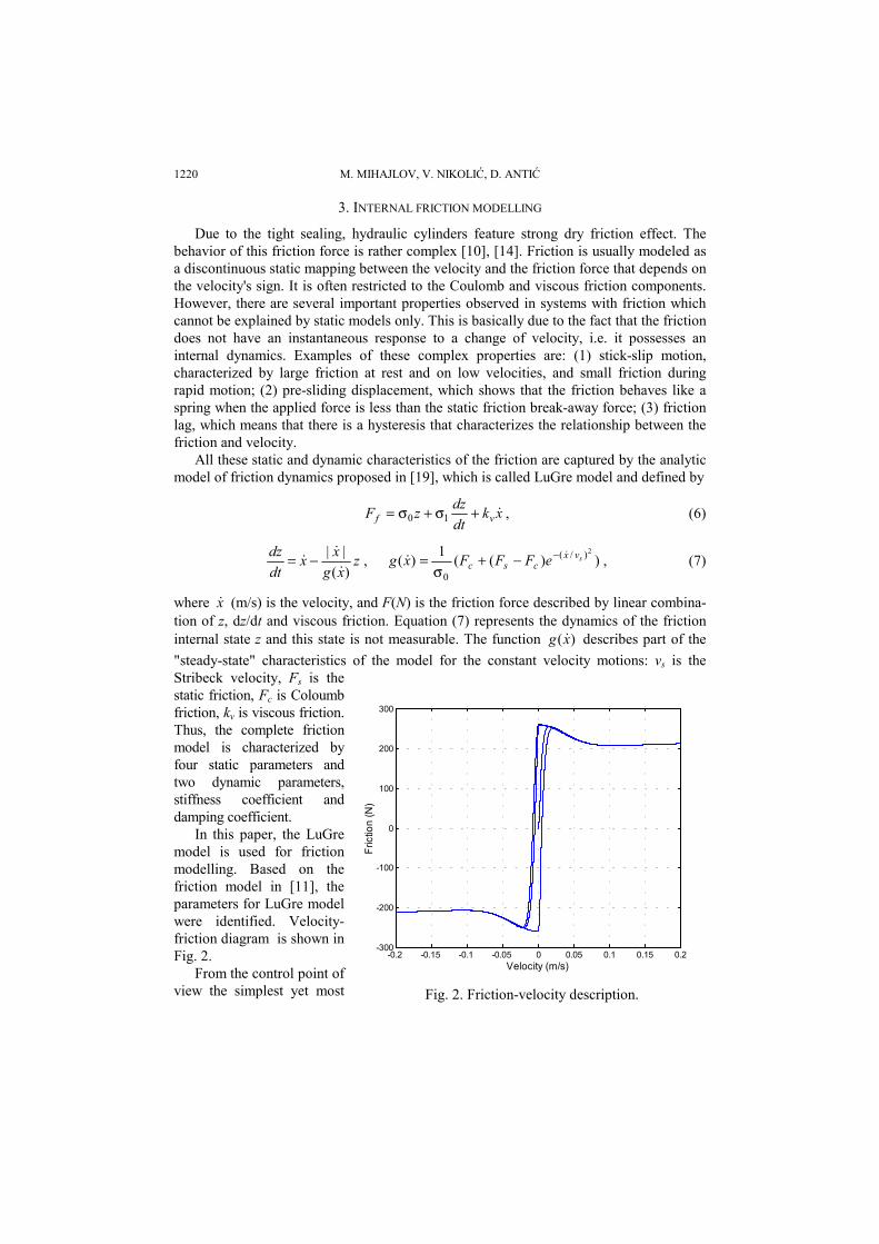
Due to the tight sealing, hydraulic cylinders feature strong dry friction effect. Thebehavior of this friction force is rather complex [10], [14]. Friction is usually modeled asa discontinuous static mapping between the velocity and the friction force that depends onthe velocity's sign. It is often restricted to the Coulomb and viscous friction components.However, there are several important properties observed in systems with friction whichcannot be explained by static models only. This is basically due to the fact that the frictiondoes not have an instantaneous response to a change of velocity, i.e. it possesses aninternal dynamics. Examples of these complex properties are: (1) stick-slip motion,characterized by large friction at rest and on low velocities, and small friction duringrapid motion; (2) pre-sliding displacement, which shows that the friction behaves like aspring when the applied force is less than the static friction break-away force; (3) frictionlag, which means that there is a hysteresis that characterizes the relationship between thefriction and velocity.
All these static and dynamic characteristics of the friction are captured by the analyticmodel of friction dynamics proposed in [19], which is called LuGre model and defined by
xkdtdzzF vf +σ+σ= 10 , (6)
zxg
xxdtdz
)(||−= , ))((1)(
2)/(
0
svxcsc eFFFxg −−+
σ= , (7)
where x (m/s) is the velocity, and F(N) is the friction force described by linear combina-tion of z, dz/dt and viscous friction. Equation (7) represents the dynamics of the frictioninternal state z and this state is not measurable. The function )(xg describes part of the"steady-state" characteristics of the model for the constant velocity motions: vs is theStribeck velocity, Fs is thestatic friction, Fc is Coloumbfriction, kv is viscous friction.Thus, the complete frictionmodel is characterized byfour static parameters andtwo dynamic parameters,stiffness coefficient anddamping coefficient.
In this paper, the LuGremodel is used for frictionmodelling. Based on thefriction model in [11], theparameters for LuGre modelwere identified. Velocity-friction diagram is shown inFig. 2.
From the control point ofview the simplest yet most
-0.2 -0.15 -0.1 -0.05 0 0.05 0.1 0.15 0.2-300
-200
-100
0
100
200
300
Velocity (m/s)
Fric
tion
(N)
Fig. 2. Friction-velocity description.

Position Control of an Electro-Hydraulic Servo System Using Sliding Mode Control ... 1221
effective approach to counteract the friction phenomenon appears to be the use of slidingmode control; in fact, one of the main characteristic of this control technique is itsrobustness against bounded uncertainties and disturbances: friction is regarded as abounded disturbance of unpredictable sign and therefore counteracted by choosing asuitable control amplitude.
4. SLIDING MODE CONTROLLER DESIGN
The sliding mode control method proposed in [17] is used in the first step of thecontroller design. Consider a nonlinear system described in control canonical form (5).The following assumptions are made:
.)(),,(|),(ˆ),(|
),,()(ˆ),(
DtdtFtftf
tbbtb
<≤−
∆+=
xxx
xxx
(7)
The nonlinear dynamics f(x,t) are not known exactly, but are estimated as ),(ˆ tf x with
errors bounded by a known function F(x,t). The term d(t) are disturbances, )(ˆ xf , )(ˆ xbcorrespond to nominal parameters of the system, and ),( tb x∆ are parameter uncertainties.
The function ),(ˆ tf x is the estimated system nonlinearity at nominal values for systemparameters. The control gain is also unknown exactly. It is bounded as
maxmin0 bbb ≤≤< . (8)
The control gain b and its bounds can be time varying or state dependent. Since thecontrol input is multiplied by the control gain in the dynamics, the geometric mean of thelower and upper bounds of the gain is taken as the estimate of b:
2/1maxmin )(ˆ bbb = . (9)
Denote by )(),()(),( 13121 txxtxtxtx ddddd == desired system states, and assumethat they are bounded. The control objective is to design a chattering attenuated slidingmode controller that provides robust performance in the presence of uncertainties, giventhe bounds ∆b(x,t) and F(x,t). To this end, the following switching function is defined:
3212
12 2)(),( eeeedtdtS +λ+λ=λ+=e , (10)
where
)()()()()()()()()()(
)()()(][
11333
11222
111
321
txtxtxtxtetxtxtxtxte
txtxteeee
dd
dd
d
T
−=−=−=−=
−==e
(11)
are the tracking errors and λ is strictly positive constant to be specified according to thedesired dynamics of the closed-loop system.
M. MIHAJLOV, V. NIKOLIĆ, D. ANTIĆ1222
The equivalent control ueq is determined by the necessary condition for existence of asliding mode 0=S with nominal values, i.e. for the system without uncertainties anddisturbances. This results in
)),(ˆ2(ˆ132
21deq xtxfeebu +−λ−λ−= − . (12)
The control law must satisfy a sliding condition regardless the estimation errors. Thus,a discontinuous term is added to (12) and total control law is as follows
sweq uuu += , (13)where
)sgn(ˆ 1 SKbusw−−= . (14)
In essence, to achieve a zero tracking error all system trajectories must be forced toconverge to S in finite time and to remain on S afterwards. By choosing the Lyapunovfunction V=0.5S2, a reaching condition is obtained as:
|),(|),(5.0 2 tStSdtdV ee η−≤= , (15)
where η is strictly positive design parameter. This leads to
|),(|),(),( tStStS eee η−≤ . (16)
Discontinuous gain K in (14) is determined such that the above condition is met. Thefinal condition for K is:
DUbFK +−β+η+β≥ ||ˆ)1()( , (17)where
FffUuDd eq ≤−≤≤ |ˆ|,||,|| , (18)
and gain margin β is introduced as
.ˆ,1/
1minmax
β≤≥=β
− bbbb (19)
Assuming that the coefficients of state equations (5) may fluctuate by 50% aroundtheir nominal values, the bounds of the uncertainties and the estimation error weredetermined:
.|ˆ| 0.5|ˆ| ;3)5.0ˆ/()5.1ˆ(/ minmax fffFbbbb =−==⋅⋅==β
In conclusion, if the switching gain K satisfies (17), the reaching condition will hold.This means that in a finite time, the tracking will be achieved, within specified errorbounds F and β.
Discontinuity in the switching control (14) usually results in chattering which mayexcite undesirable high-frequency or unmodelled dynamics. The simple and wide-usedmethod to alleviate chattering is to replace a sign function in discontinuous term in thecontrol law by a saturating continuos approximation that introduces the concept ofboundary layer:

Position Control of an Electro-Hydraulic Servo System Using Sliding Mode Control ... 1223
)/tanh(ˆ 1 φ−= − SKbusw , (20)
where φ>0 is the thickness of the boundary layer and its value is to be adjusted to achievean optimal balance between the position error and the level of control chattering.
5. FUZZY CONTROLLER DESIGN
To reduce the tracking error in the case of sliding mode controller with fixed boundarylayer given in the previous section, the introduction of fuzzy controller is considered,following the idea [16]. However, unlike this solution, a fuzzy PI controller ofincremental type is used. The motivation for choosing this type of fuzzy controller is toalleviate the problems in calculation the switching gain, and to improve operatingefficiency in the presence of additional external disturbance that is not taken into accountin the design for SMC.
The fuzzy controller acts complementary to the SMC controller and total control lowis
fbsweq uuuu ++= , (21)
where ueq and usw are given by (12) and (20), respectively. The term ufb in (21) is theoutput of the fuzzy PI controller whose design procedure is explained in the following.
The inputs to the fuzzy controller are the position tracking error e1 and the velocitytracking error e2. The output of the fuzzy controller is the control signal increment. Fuzzyrules are obtained based on the following reasoning: if the position tracking error isNegative and if the velocity tracking error is Negative then the control signal is to beincreased for Positive Big value.
Number of fuzzy values of fuzzy controller inputs, shape and location of membershipfunctions, and inference mechanism (max-min method, centre of gravity asdefuzzification method) are the same or similar as in [16]. Fuzzy values of controllerinputs and controller output are shown in Fig. 3. The type of fuzzy controller and the rulebase are essentially different, according to the role of fuzzy controller in this problem.
-1 -0.5 0 0.5 1
0
0.2
0.4
0.6
0.8
1
e1, e2
Deg
ree
of m
embe
rshi
p
N P
-2 -1.5 -1 -0.5 0 0.5 1 1.5 2
0
0.2
0.4
0.6
0.8
1
delta Ufb
NB N P PB
a) b)Fig. 3. Fuzzy values of fuzzy controller inputs (a) and output (b).
M. MIHAJLOV, V. NIKOLIĆ, D. ANTIĆ1224
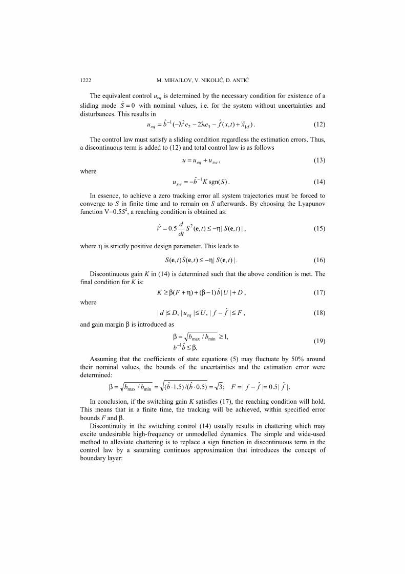
The set of fuzzy rules is as follows:
NBisthenPisandPisIf4.NisthenNisandPisIf3.PisthenPisandNisIf2.PBisthenNisandNisIf1.
outputerrorinchangeerroroutputerrorinchangeerroroutputerrorinchangeerroroutputerrorinchangeerror
The input-output mapping which is the result of inference by the fuzzy rules is shownin Fig. 4.
Fig. 4. Input-output mapping of the fuzzy PI controller
6. SIMULATION RESULTS
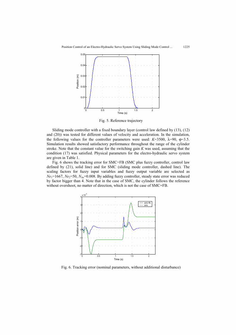
For high performance, it is necessary to incorporate as much prior information on thedesired trajectory into the controller design as possible. In the particular case, the slidingmode controller makes use of the third derivative of the desired trajectory. In order toprovide a feasible reference motion trajectory that the actuator can track and to avoidovershoots, the maximum values of desired velocity and acceleration were determined onthe ground of mathematical and simulation model of the electro-hydraulic servo system,taking into account the maximum value of the control voltage umax=10V. Then, acontinuously differentiable velocity profile was determined. The reference trajectory,obtained in such a way, is shown in Fig. 5.
Position Control of an Electro-Hydraulic Servo System Using Sliding Mode Control ... 1225
0 0.5 1 1.5 20
0.01
0.02
0.03
0.04
0.05
Time (s)
Posi
tion
(m)
Fig. 5. Reference trajectory
Sliding mode controller with a fixed boundary layer (control law defined by (13), (12)and (20)) was tested for different values of velocity and acceleration. In the simulation,the following values for the controller parameters were used: K=3500, λ=90, ϕ=3.5.Simulation results showed satisfactory performance throughout the range of the cylinderstroke. Note that the constant value for the switching gain K was used, assuming that thecondition (17) was satisfied. Physical parameters for the electro-hydraulic servo systemare given in Table 1.
Fig. 6 shows the tracking error for SMC+FB (SMC plus fuzzy controller, control lawdefined by (21), solid line) and for SMC (sliding mode controller, dashed line). Thescaling factors for fuzzy input variables and fuzzy output variable are selected asNe1=1667, Ne2=50, N∆u=0.008. By adding fuzzy controller, steady state error was reducedby factor bigger than 4. Note that in the case of SMC, the cylinder follows the referencewithout overshoot, no matter of direction, which is not the case of SMC+FB.
0 0.5 1 1.5 2-3
-2
-1
0
1
2
3
4x 10
-4
Time (s)
Posit
ion
erro
r (m
)
smc+fbsmc
Fig. 6. Tracking error (nominal parameters, without additional disturbance)

M. MIHAJLOV, V. NIKOLIĆ, D. ANTIĆ1226
In Fig. 7 the values of control signals are depicted. Fig. 8 shows the chosen slidingfunction dynamics with and without the fuzzy control. In both cases, the system stateremains inside the boundary layer, starting from e=[0 0 0]T.
0 0.5 1 1.5 2-6
-4
-2
0
2
4
6
Time (s)
Con
trol v
olta
ge (V
)
smc+fbsmc
Fig. 7. Control signal (nominal parameters, without additional disturbance)
To examine the performance of SMC+FB under conditions when SMC does not followthe reference trajectory, an additional disturbance of step type was involved, starting fromt=0.7 s. This additional disturbance was chosen as a force Fd=1 kN. Fig. 9 shows the systemresponse in the presence of this disturbance. It is to emphasize that the purpose of this figureis not to compare SMC with and without the fuzzy controller, than to illustrate that themagnitude of disturbance is such that SMC cannot fulfill the given task.
0 0.5 1 1.5 2-4
-3
-2
-1
0
1
2
3
4
Time (s)
S
smc+fbsmc
Fig. 8. Sliding surface (nominal parameters, without additional disturbance)

Position Control of an Electro-Hydraulic Servo System Using Sliding Mode Control ... 1227
0 0.5 1 1.5 2-0.01
0
0.01
0.02
0.03
0.04
0.05
Time (s)
Posit
ion
(m)
smc+fbsmc
Fig. 9. System response in the presence of additional external disturbance
The tracking error of SMC+FB is shown in Fig. 10. It is clear that completeelimination of the additional disturbance was achieved in approximately 0.3 s.Furthermore, steady state error is the same as without additional disturbance.
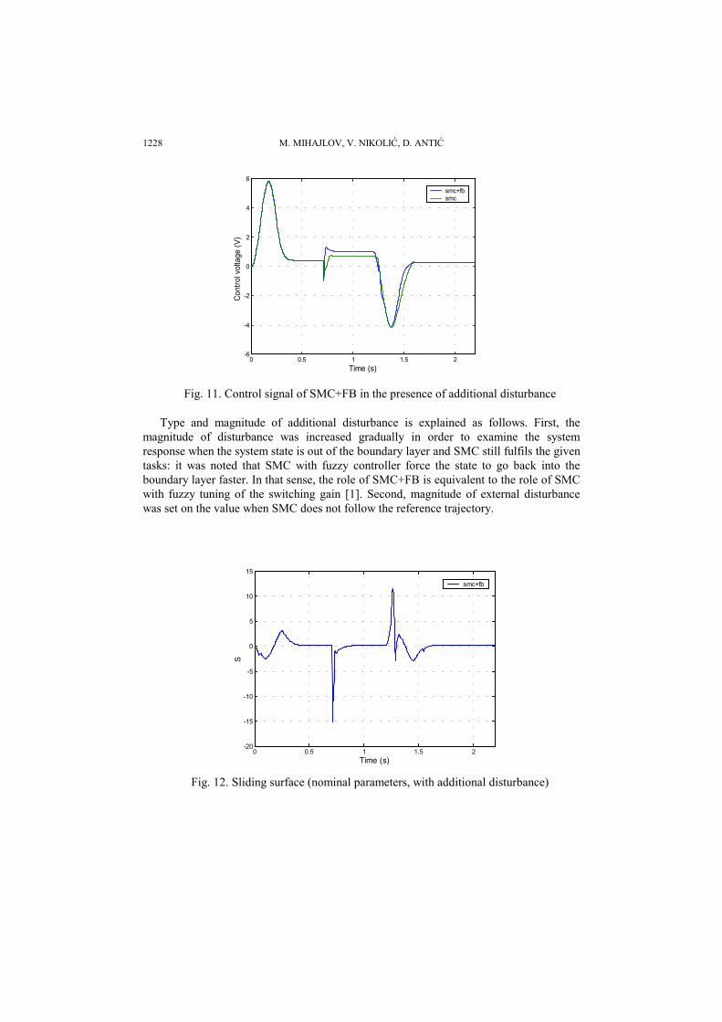
From Fig. 11, the difference in control signal as a consequence of adding the fuzzycontroller is clearly seen. The sliding function dynamics for this case is depicted in Fig. 12.
0 0.5 1 1.5 2-8
-6
-4
-2
0
2
4
6
8x 10
-4
Time (s)
Posi
tion
erro
r (m
)
smc+fb
Fig. 10. Tracking error of SMC+FB in the presence of additional disturbance
M. MIHAJLOV, V. NIKOLIĆ, D. ANTIĆ1228
0 0.5 1 1.5 2-6
-4
-2
0
2
4
6
Time (s)
Cont
rol v
olta
ge (V
)
smc+fbsmc
Fig. 11. Control signal of SMC+FB in the presence of additional disturbance
Type and magnitude of additional disturbance is explained as follows. First, themagnitude of disturbance was increased gradually in order to examine the systemresponse when the system state is out of the boundary layer and SMC still fulfils the giventasks: it was noted that SMC with fuzzy controller force the state to go back into theboundary layer faster. In that sense, the role of SMC+FB is equivalent to the role of SMCwith fuzzy tuning of the switching gain [1]. Second, magnitude of external disturbancewas set on the value when SMC does not follow the reference trajectory.
0 0.5 1 1.5 2-20
-15
-10
-5
0
5
10
15
Time (s)
S
smc+fb
Fig. 12. Sliding surface (nominal parameters, with additional disturbance)
Position Control of an Electro-Hydraulic Servo System Using Sliding Mode Control ... 1229
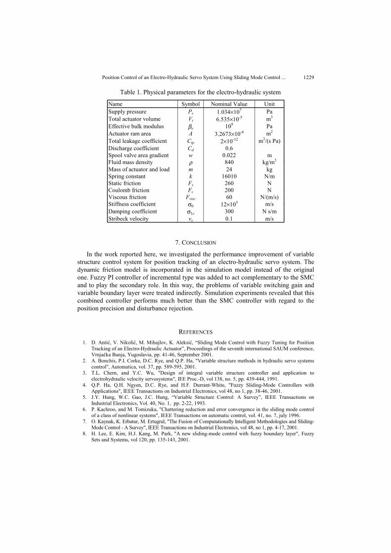
Table 1. Physical parameters for the electro-hydraulic system
Name Symbol Nominal Value UnitSupply pressure Ps 1.034×10⁷ PaTotal actuator volume Vt 6.535×10⁻⁵ m3
Effective bulk modulus βe 109 PaActuator ram area A 3.2673×10⁻⁴ m2
Total leakage coefficient Ctp 2×10-12 m3/(s Pa)Discharge coefficient Cd 0.6Spool valve area gradient w 0.022 mFluid mass density ρ 840 kg/m3
Mass of actuator and load m 24 kgSpring constant k 16010 N/mStatic friction Fs 260 NCoulomb friction Fc 200 NViscous friction Fvisc 60 N/(m/s)Stiffness coefficient σ0 12×105 m/sDamping coefficient σ1e 300 N s/mStribeck velocity vs 0.1 m/s
7. CONCLUSION
In the work reported here, we investigated the performance improvement of variablestructure control system for position tracking of an electro-hydraulic servo system. Thedynamic friction model is incorporated in the simulation model instead of the originalone. Fuzzy PI controller of incremental type was added to act complementary to the SMCand to play the secondary role. In this way, the problems of variable switching gain andvariable boundary layer were treated indirectly. Simulation experiments revealed that thiscombined controller performs much better than the SMC controller with regard to theposition precision and disturbance rejection.
REFERENCES
1. D. Antić, V. Nikolić, M. Mihajlov, K. Aleksić, “Sliding Mode Control with Fuzzy Tuning for PositionTracking of an Electro-Hydraulic Actuator”, Proceedings of the seventh international SAUM conference,Vrnjačka Banja, Yugoslavia, pp. 41-46, September 2001.
2. A. Bonchis, P.I. Corke, D.C. Rye, and Q.P. Ha, "Variable structure methods in hydraulic servo systemscontrol", Automatica, vol. 37, pp. 589-595, 2001.
3. T.L. Chern, and Y.C. Wu, "Design of integral variable structure controller and application toelectrohydraulic velocity servosystems", IEE Proc.-D, vol 138, no. 5, pp. 439-444, 1991.
4. Q.P. Ha, Q.H. Ngyen, D.C. Rye, and H.F. Durrant-White, "Fuzzy Sliding-Mode Controllers withApplications", IEEE Transactions on Industrial Electronics, vol 48, no 1, pp. 38-46, 2001.
5. J.Y. Hung, W.C. Gao, J.C. Hung, “Variable Structure Control: A Survey”, IEEE Transactions onIndustrial Electronics, Vol. 40, No. 1, pp. 2-22, 1993.
6. P. Kachroo, and M. Tomizuka, "Chattering reduction and error convergence in the sliding mode controlof a class of nonlinear systems", IEEE Transactions on automatic control, vol. 41, no. 7, july 1996.
7. O. Kaynak, K. Erbatur, M. Ertugrul, "The Fusion of Computationally Intelligent Methodologies and Sliding-Mode Control - A Survey", IEEE Transactions on Industrial Electronics, vol 48, no 1, pp. 4-17, 2001.
8. H. Lee, E. Kim, H.J. Kang, M. Park, "A new sliding-mode control with fuzzy boundary layer", FuzzySets and Systems, vol 120, pp. 135-143, 2001.

M. MIHAJLOV, V. NIKOLIĆ, D. ANTIĆ1230
9. Y. Liu, and H. Handroos, "Sliding mode control for a class of hydraulic position servo", Mechatronics,vol. 9, pp. 111-123, 1999.
10. P. Lischinsky, C.C. de Wit, and G. Morel, "Friction Compensation for an Industrial Hydraulic Robot",IEEE Control Systems, pp. 25-32, February 1999.
11. R. Liu, and A. Alleyne, "Nonlinear Force/Pressure Tracking of an Electro-Hydraulic Actuator", ASMEJournal of Dynamic Systems, Measurement, and Control, vol. 122, pp. 232-237, 2000.
12. H.E. Merritt, Hydraulic Control Systems, New York: John Wiley & Sons, Inc., 1967. 13. V. Nikolić, D. Antić, and M. Mihajlov, "Position Control of an Electro-hydraulic Servo System using
Sliding Mode Control with Fuzzy Boundary Layer", 8th conference on Vehicle System Dynamics,Identification and Anomalies, Budapest, Hungary, (to be published), 11-13 November, 2002.
14. C.H. Olsson, K.J. Åström, C.C. de Wit, and P. Lischinsky, "Friction Models and FrictionCompensation", European Journal on Control, 1998.
15. R. Palm, D. Driankov, H. Hellendoorn, Model Based Fuzzy Control, Berlin: Springer-Verlag, 1997. 16. D. Sha, V.B. Bajić, X. Li, and X. Wang, "Real-time Experiments with Discrete Sliding-Mode Control
Enhanced by AI Components", Journal of Applied Computer Science, Vol. 8, No.2, pp.99-117, 2000. 17. J.J. Slotine, and W. Li, Applied Nonlinear Control, Englewood Cliffs, NJ: Prentice Hall, 1991. 18. G.A. Sohl, and B.J. Bobrow "Experiments and Simulations on the Nonlinear Control of a Hydraulic
Servosystem", IEEE Transactions on Control Systems Tehnology, Vol. 7, No. 2., pp. 238-247, 1999. 19. C.C. de Wit, C.H. Olsson, K.J. Åström and P. Lischinsky, "A New Model for Control Systems with
Friction", IEEE Transactions on Automatic Control, Vol. 40, No. 3, pp. 419-425, 1995.
UPRAVLJANJE POZICIJOM ELEKTROHIDRAULIČKOGSISTEMA PRIMENOM REGULATORA PROMENLJIVESTRUKTURE PROŠIRENOG FAZI PI REGULATOROM
Miroslav Mihajlov, Vlastimir Nikolić, Dragan Antić
U ovom radu je primenjen regulator promenljive strukture proširen fazi PI regulatorom na tipičnielektrohidraulički sistem čiji matematički model obuhvata glavne nelinearnosti, uklučujući trenje uhidrauličkom cilindru. Razmatran je problem upravljanja pozicijom u prisustvu nemodeliranedinamike, parametarskih neodređenosti i spoljašnjih poremećaja. Uvođenjem fazi regulatora udirektnu granu zatvorenog kola poboljšane su performanse sistema upravljanja promenljive strukturesa fiksnim graničnim slojem u odnosu na tačnost praćenja zadate trajektorije i eliminaciju spoljašnjegporemećaja. Poboljšanje performansi je ilustrovano rezultatima simulacije.