Embed Size (px)
Citation preview
POSIDRIVE® MDS 5000
Projecting manual InstallationConnecting
Accessories
V 5.6-N or later
03/2015
en
Table of contents
2
Projecting manual POSIDRIVE® MDS 5000
WE
KE
EP
TH
ING
S M
OV
ING
Table of contents
1 Introduction . . . . . . . . . . . . . . . . . . . . . . . . . . . . . . . . . . . . . . . . . . . . . . . . . . . . . . . . . . . . . . . . . ..6
1.1 Purpose of the manual . . . . . . . . . . . . . . . . . . . . . . . . . . . . . . . . . . . . . . . . . . . . . . . . . . . . . . . 6
1.2 Further documentation . . . . . . . . . . . . . . . . . . . . . . . . . . . . . . . . . . . . . . . . . . . . . . . . . . . . . . . 6
1.3 Further support . . . . . . . . . . . . . . . . . . . . . . . . . . . . . . . . . . . . . . . . . . . . . . . . . . . . . . . . . . . . . 6
1.4 Abbreviations, formula symbols and indices . . . . . . . . . . . . . . . . . . . . . . . . . . . . . . . . . . . . . . 7
1.5 Symbols, identifiers, marks .. . . . . . . . . . . . . . . . . . . . . . . . . . . . . . . . . . . . . . . . . . . . . . . . . . . 9
2 Notes on safety . . . . . . . . . . . . . . . . . . . . . . . . . . . . . . . . . . . . . . . . . . . . . . . . . . . . . . . . . . . . .11
2.1 Component part of the product .. . . . . . . . . . . . . . . . . . . . . . . . . . . . . . . . . . . . . . . . . . . . . . . .11
2.2 Operation in accordance with its intended use .. . . . . . . . . . . . . . . . . . . . . . . . . . . . . . . . . . . .11
2.3 Risk assessment . . . . . . . . . . . . . . . . . . . . . . . . . . . . . . . . . . . . . . . . . . . . . . . . . . . . . . . . . . .11
2.4 Ambient conditions . . . . . . . . . . . . . . . . . . . . . . . . . . . . . . . . . . . . . . . . . . . . . . . . . . . . . . . . . 12
2.5 Qualified personnel . . . . . . . . . . . . . . . . . . . . . . . . . . . . . . . . . . . . . . . . . . . . . . . . . . . . . . . . 12
2.6 Transportation and storage . . . . . . . . . . . . . . . . . . . . . . . . . . . . . . . . . . . . . . . . . . . . . . . . . . 13
2.7 Installation and connection . . . . . . . . . . . . . . . . . . . . . . . . . . . . . . . . . . . . . . . . . . . . . . . . . . . 13
2.8 Commissioning, operation and service .. . . . . . . . . . . . . . . . . . . . . . . . . . . . . . . . . . . . . . . . . 14
2.9 Disposal . . . . . . . . . . . . . . . . . . . . . . . . . . . . . . . . . . . . . . . . . . . . . . . . . . . . . . . . . . . . . . . . . 15
2.10 Residual dangers . . . . . . . . . . . . . . . . . . . . . . . . . . . . . . . . . . . . . . . . . . . . . . . . . . . . . . . . . . 15
2.11 UL-compliant use . . . . . . . . . . . . . . . . . . . . . . . . . . . . . . . . . . . . . . . . . . . . . . . . . . . . . . . . . . 15
2.12 Presentation of notes on safety . . . . . . . . . . . . . . . . . . . . . . . . . . . . . . . . . . . . . . . . . . . . . . . 17
3 Technical data . . . . . . . . . . . . . . . . . . . . . . . . . . . . . . . . . . . . . . . . . . . . . . . . . . . . . . . . . . . . . .18
3.1 General data of the inverters . . . . . . . . . . . . . . . . . . . . . . . . . . . . . . . . . . . . . . . . . . . . . . . . . 18
3.1.1 Transportation, storage and operating environment . . . . . . . . . . . . . . . . . . . . . . . . 18
3.1.2 Device features . . . . . . . . . . . . . . . . . . . . . . . . . . . . . . . . . . . . . . . . . . . . . . . . . . . . 19
3.1.3 Weight . . . . . . . . . . . . . . . . . . . . . . . . . . . . . . . . . . . . . . . . . . . . . . . . . . . . . . . . . . . 19
3.2 Electrical data of the inverters . . . . . . . . . . . . . . . . . . . . . . . . . . . . . . . . . . . . . . . . . . . . . . . . 20
3.2.1 Size 0 (BG 0): MDS 5007 to MDS 5015 . . . . . . . . . . . . . . . . . . . . . . . . . . . . . . . . . 20
3.2.2 Size 1 (BG 1): MDS 5040 to MDS 5075 . . . . . . . . . . . . . . . . . . . . . . . . . . . . . . . . . 22
ID 442273.07

Table of contentsProjecting manual POSIDRIVE® MDS 5000
WE
KE
EP
TH
ING
S M
OV
ING
3.2.3 Size 2 (BG 2): MDS 5110 and MDS 5150 . . . . . . . . . . . . . . . . . . . . . . . . . . . . . . . . 23
3.2.4 Size 3 (BG 3): MDS 5220 to MDS 5450 . . . . . . . . . . . . . . . . . . . . . . . . . . . . . . . . . 24
3.2.5 Derating by increasing the switching frequency .. . . . . . . . . . . . . . . . . . . . . . . . . . 25
3.3 Dimensions .. . . . . . . . . . . . . . . . . . . . . . . . . . . . . . . . . . . . . . . . . . . . . . . . . . . . . . . . . . . . . . 26
3.3.1 Size 0 to 2: MDS 5007 to MDS 5150 . . . . . . . . . . . . . . . . . . . . . . . . . . . . . . . . . . . 26
3.3.2 Size 3: MDS 5220 to MDS 5450 . . . . . . . . . . . . . . . . . . . . . . . . . . . . . . . . . . . . . . . 28
3.4 Brake resistors MDS 5xxx . . . . . . . . . . . . . . . . . . . . . . . . . . . . . . . . . . . . . . . . . . . . . . . . . . . 30
3.4.1 FZMU, FZZM .. . . . . . . . . . . . . . . . . . . . . . . . . . . . . . . . . . . . . . . . . . . . . . . . . . . . . 30
3.4.2 VHPR . . . . . . . . . . . . . . . . . . . . . . . . . . . . . . . . . . . . . . . . . . . . . . . . . . . . . . . . . . . 32
3.4.3 FZZT, FZDT and FGFT . . . . . . . . . . . . . . . . . . . . . . . . . . . . . . . . . . . . . . . . . . . . . . 34
3.4.4 Bottom brake resistor RB 5000 . . . . . . . . . . . . . . . . . . . . . . . . . . . . . . . . . . . . . . . 36
3.5 Brake resistors MDS 5xxxA . . . . . . . . . . . . . . . . . . . . . . . . . . . . . . . . . . . . . . . . . . . . . . . . . . 37
3.5.1 FZMU, FZZMU . . . . . . . . . . . . . . . . . . . . . . . . . . . . . . . . . . . . . . . . . . . . . . . . . . . . 37
3.5.2 GVADU, GBADU . . . . . . . . . . . . . . . . . . . . . . . . . . . . . . . . . . . . . . . . . . . . . . . . . . . 39
3.5.3 FGFKU . . . . . . . . . . . . . . . . . . . . . . . . . . . . . . . . . . . . . . . . . . . . . . . . . . . . . . . . . . 40
3.5.4 Bottom brake resistor RB 5000 . . . . . . . . . . . . . . . . . . . . . . . . . . . . . . . . . . . . . . . 42
3.6 Output derater . . . . . . . . . . . . . . . . . . . . . . . . . . . . . . . . . . . . . . . . . . . . . . . . . . . . . . . . . . . . 43
4 Installation . . . . . . . . . . . . . . . . . . . . . . . . . . . . . . . . . . . . . . . . . . . . . . . . . . . . . . . . . . . . . . . . . .48
4.1 Installation of the inverter in the switching cabinet . . . . . . . . . . . . . . . . . . . . . . . . . . . . . . . . . 48
4.2 Accessories . . . . . . . . . . . . . . . . . . . . . . . . . . . . . . . . . . . . . . . . . . . . . . . . . . . . . . . . . . . . . . 50
4.2.1 Installation of bottom brake resistor . . . . . . . . . . . . . . . . . . . . . . . . . . . . . . . . . . . . 50
4.2.2 Installation of EMC shroud or brake module . . . . . . . . . . . . . . . . . . . . . . . . . . . . . . 52
4.2.3 Installation of the terminal accessories . . . . . . . . . . . . . . . . . . . . . . . . . . . . . . . . . . 55
4.2.4 Installation of CANopen, PROFIBUS, EtherCAT or PROFINET accessories .. . . . . 58
5 Connection . . . . . . . . . . . . . . . . . . . . . . . . . . . . . . . . . . . . . . . . . . . . . . . . . . . . . . . . . . . . . . . . .63
5.1 Overview of terminals . . . . . . . . . . . . . . . . . . . . . . . . . . . . . . . . . . . . . . . . . . . . . . . . . . . . . . . 63
5.2 EMC connection . . . . . . . . . . . . . . . . . . . . . . . . . . . . . . . . . . . . . . . . . . . . . . . . . . . . . . . . . . . 66
5.3 X10: 230 V/400 V power . . . . . . . . . . . . . . . . . . . . . . . . . . . . . . . . . . . . . . . . . . . . . . . . . . . . 67
5.3.1 Line fuse . . . . . . . . . . . . . . . . . . . . . . . . . . . . . . . . . . . . . . . . . . . . . . . . . . . . . . . . . 68
ID 442273.07 3
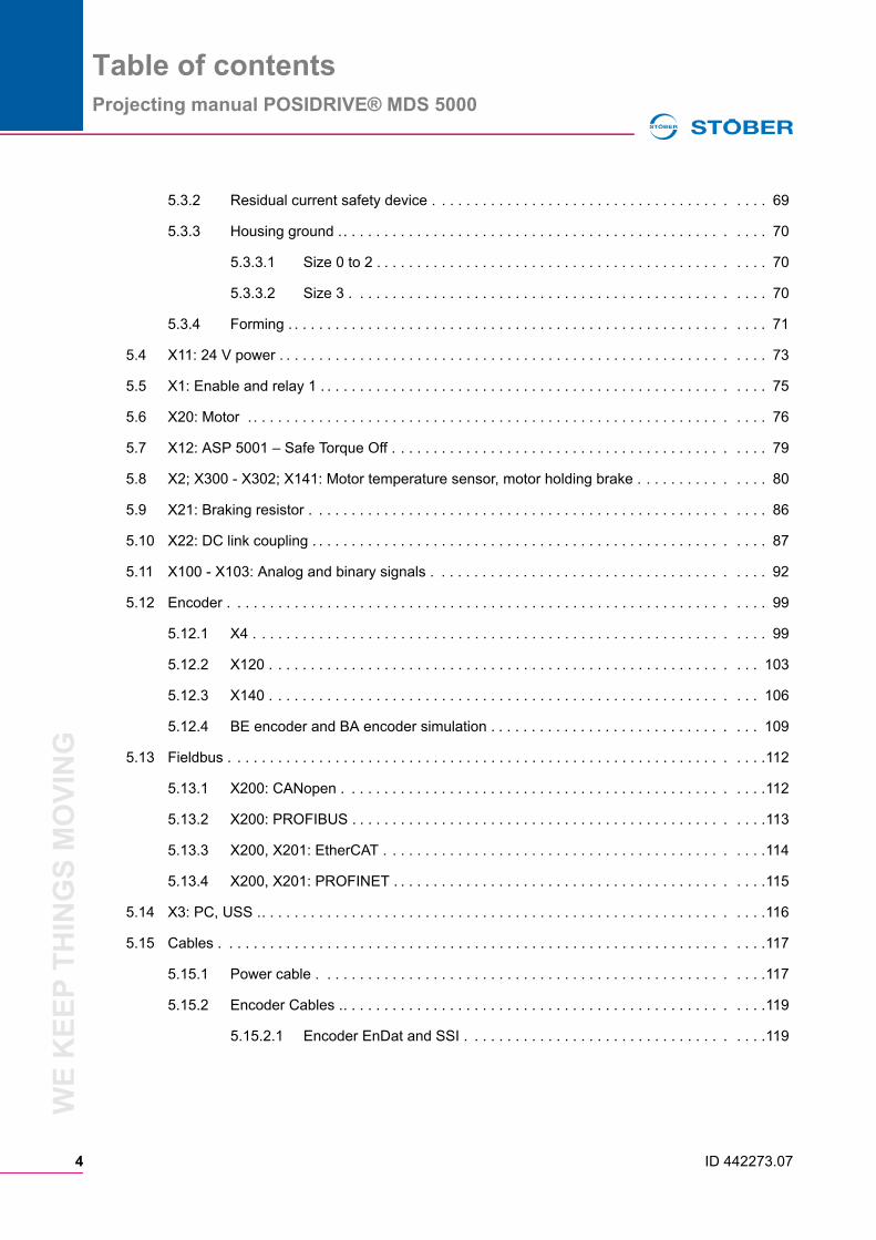
Table of contents
4
Projecting manual POSIDRIVE® MDS 5000
WE
KE
EP
TH
ING
S M
OV
ING
5.3.2 Residual current safety device . . . . . . . . . . . . . . . . . . . . . . . . . . . . . . . . . . . . . . . . 69
5.3.3 Housing ground .. . . . . . . . . . . . . . . . . . . . . . . . . . . . . . . . . . . . . . . . . . . . . . . . . . . 70
5.3.3.1 Size 0 to 2 . . . . . . . . . . . . . . . . . . . . . . . . . . . . . . . . . . . . . . . . . . . . . . . 70
5.3.3.2 Size 3 . . . . . . . . . . . . . . . . . . . . . . . . . . . . . . . . . . . . . . . . . . . . . . . . . . 70
5.3.4 Forming . . . . . . . . . . . . . . . . . . . . . . . . . . . . . . . . . . . . . . . . . . . . . . . . . . . . . . . . . . 71
5.4 X11: 24 V power . . . . . . . . . . . . . . . . . . . . . . . . . . . . . . . . . . . . . . . . . . . . . . . . . . . . . . . . . . . 73
5.5 X1: Enable and relay 1 . . . . . . . . . . . . . . . . . . . . . . . . . . . . . . . . . . . . . . . . . . . . . . . . . . . . . . 75
5.6 X20: Motor . . . . . . . . . . . . . . . . . . . . . . . . . . . . . . . . . . . . . . . . . . . . . . . . . . . . . . . . . . . . . . . 76
5.7 X12: ASP 5001 – Safe Torque Off . . . . . . . . . . . . . . . . . . . . . . . . . . . . . . . . . . . . . . . . . . . . . 79
5.8 X2; X300 - X302; X141: Motor temperature sensor, motor holding brake . . . . . . . . . . . . . . . 80
5.9 X21: Braking resistor . . . . . . . . . . . . . . . . . . . . . . . . . . . . . . . . . . . . . . . . . . . . . . . . . . . . . . . 86
5.10 X22: DC link coupling . . . . . . . . . . . . . . . . . . . . . . . . . . . . . . . . . . . . . . . . . . . . . . . . . . . . . . . 87
5.11 X100 - X103: Analog and binary signals . . . . . . . . . . . . . . . . . . . . . . . . . . . . . . . . . . . . . . . . 92
5.12 Encoder . . . . . . . . . . . . . . . . . . . . . . . . . . . . . . . . . . . . . . . . . . . . . . . . . . . . . . . . . . . . . . . . . 99
5.12.1 X4 . . . . . . . . . . . . . . . . . . . . . . . . . . . . . . . . . . . . . . . . . . . . . . . . . . . . . . . . . . . . . . 99
5.12.2 X120 . . . . . . . . . . . . . . . . . . . . . . . . . . . . . . . . . . . . . . . . . . . . . . . . . . . . . . . . . . . 103
5.12.3 X140 . . . . . . . . . . . . . . . . . . . . . . . . . . . . . . . . . . . . . . . . . . . . . . . . . . . . . . . . . . . 106
5.12.4 BE encoder and BA encoder simulation . . . . . . . . . . . . . . . . . . . . . . . . . . . . . . . . 109
5.13 Fieldbus . . . . . . . . . . . . . . . . . . . . . . . . . . . . . . . . . . . . . . . . . . . . . . . . . . . . . . . . . . . . . . . . .112
5.13.1 X200: CANopen . . . . . . . . . . . . . . . . . . . . . . . . . . . . . . . . . . . . . . . . . . . . . . . . . . .112
5.13.2 X200: PROFIBUS . . . . . . . . . . . . . . . . . . . . . . . . . . . . . . . . . . . . . . . . . . . . . . . . . .113
5.13.3 X200, X201: EtherCAT . . . . . . . . . . . . . . . . . . . . . . . . . . . . . . . . . . . . . . . . . . . . . .114
5.13.4 X200, X201: PROFINET . . . . . . . . . . . . . . . . . . . . . . . . . . . . . . . . . . . . . . . . . . . . .115
5.14 X3: PC, USS .. . . . . . . . . . . . . . . . . . . . . . . . . . . . . . . . . . . . . . . . . . . . . . . . . . . . . . . . . . . . .116
5.15 Cables . . . . . . . . . . . . . . . . . . . . . . . . . . . . . . . . . . . . . . . . . . . . . . . . . . . . . . . . . . . . . . . . . .117
5.15.1 Power cable . . . . . . . . . . . . . . . . . . . . . . . . . . . . . . . . . . . . . . . . . . . . . . . . . . . . . .117
5.15.2 Encoder Cables .. . . . . . . . . . . . . . . . . . . . . . . . . . . . . . . . . . . . . . . . . . . . . . . . . . .119
5.15.2.1 Encoder EnDat and SSI . . . . . . . . . . . . . . . . . . . . . . . . . . . . . . . . . . . .119
ID 442273.07

Table of contentsProjecting manual POSIDRIVE® MDS 5000
WE
KE
EP
TH
ING
S M
OV
ING
5.15.2.2 Encoder EnDat Sin/Cos . . . . . . . . . . . . . . . . . . . . . . . . . . . . . . . . . . . 122
5.15.2.3 Encoder HTL . . . . . . . . . . . . . . . . . . . . . . . . . . . . . . . . . . . . . . . . . . . . 125
5.15.2.4 Resolver . . . . . . . . . . . . . . . . . . . . . . . . . . . . . . . . . . . . . . . . . . . . . . . 126
6 Examples of connections . . . . . . . . . . . . . . . . . . . . . . . . . . . . . . . . . . . . . . . . . . . . . . . . . .129
7 Accessories . . . . . . . . . . . . . . . . . . . . . . . . . . . . . . . . . . . . . . . . . . . . . . . . . . . . . . . . . . . . . . .131
ID 442273.07 5
Introduction
6
Projecting manual POSIDRIVE® MDS 5000
1W
E K
EE
P T
HIN
GS
MO
VIN
G
1 Introduction
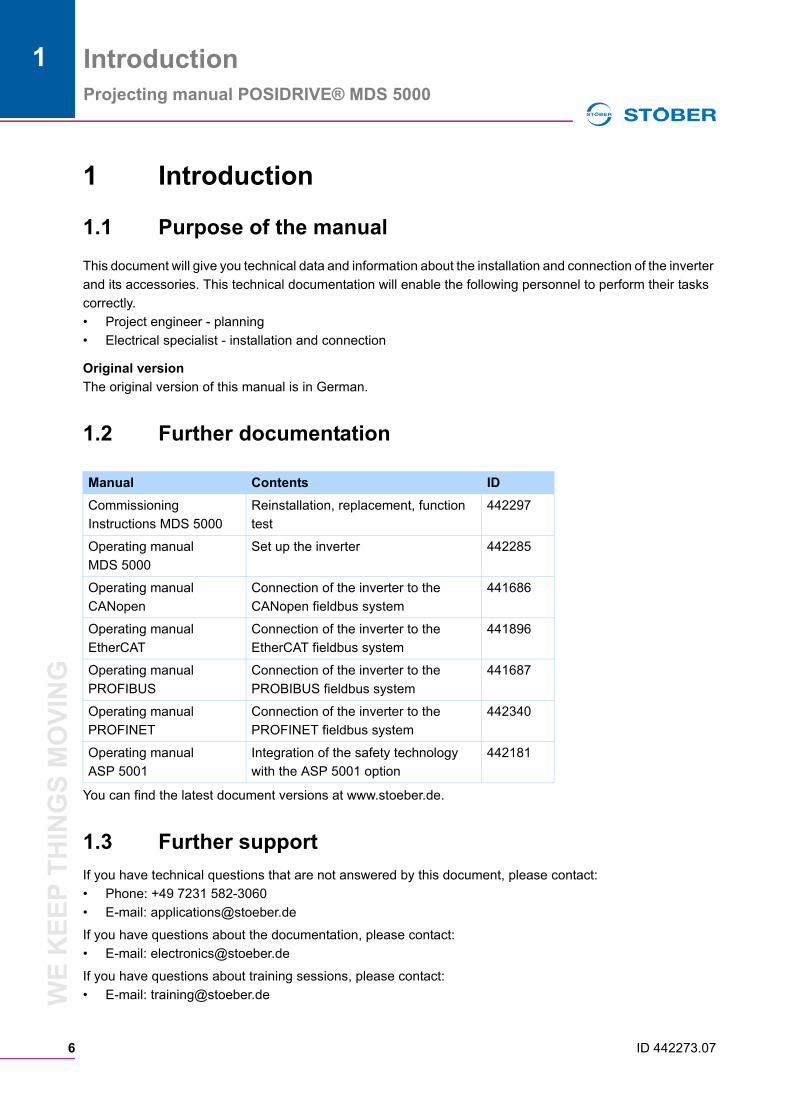
1.1 Purpose of the manual
This document will give you technical data and information about the installation and connection of the inverter
and its accessories. This technical documentation will enable the following personnel to perform their tasks
correctly.
• Project engineer - planning
• Electrical specialist - installation and connection
Original version
The original version of this manual is in German.
1.2 Further documentation
You can find the latest document versions at www.stoeber.de.
1.3 Further support
If you have technical questions that are not answered by this document, please contact:
• Phone: +49 7231 582-3060
• E-mail: [email protected]
If you have questions about the documentation, please contact:
• E-mail: [email protected]
If you have questions about training sessions, please contact:
• E-mail: [email protected]
Manual Contents ID
Commissioning
Instructions MDS 5000
Reinstallation, replacement, function
test
442297
Operating manual MDS 5000
Set up the inverter 442285
Operating manual
CANopen
Connection of the inverter to the
CANopen fieldbus system
441686
Operating manual
EtherCAT
Connection of the inverter to the
EtherCAT fieldbus system
441896
Operating manual
PROFIBUS
Connection of the inverter to the
PROBIBUS fieldbus system
441687
Operating manual
PROFINET
Connection of the inverter to the
PROFINET fieldbus system
442340
Operating manual ASP 5001
Integration of the safety technology
with the ASP 5001 option
442181
ID 442273.07
IntroductionProjecting manual POSIDRIVE® MDS 5000
WE
KE
EP
TH
ING
S M
OV
ING
1
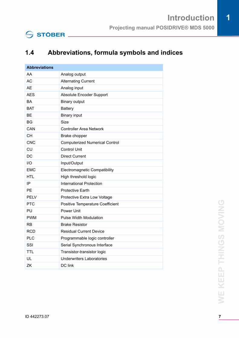
1.4 Abbreviations, formula symbols and indices
Abbreviations
AA Analog output
AC Alternating Current
AE Analog input
AES Absolute Encoder Support
BA Binary output
BAT Battery
BE Binary input
BG Size
CAN Controller Area Network
CH Brake chopper
CNC Computerized Numerical Control
CU Control Unit
DC Direct Current
I/O Input/Output
EMC Electromagnetic Compatibility
HTL High threshold logic
IP International Protection
PE Protective Earth
PELV Protective Extra Low Voltage
PTC Positive Temperature Coefficient
PU Power Unit
PWM Pulse Width Modulation
RB Brake Resistor
RCD Residual Current Device
PLC Programmable logic controller
SSI Serial Synchronous Interface
TTL Transistor-transistor logic
UL Underwriters Laboratories
ZK DC link
ID 442273.07 7
Introduction
8
Projecting manual POSIDRIVE® MDS 5000
1W
E K
EE
P T
HIN
GS
MO
VIN
G
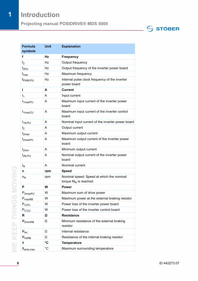
Formula
symbols
Unit Explanation
f Hz Frequency
f2 Hz Output frequency
f2PU Hz Output frequency of the inverter power board
fmax Hz Maximum frequency
fPWM,PU Hz Internal pulse clock frequency of the inverter
power board
I A Current
I1 A Input current
I1maxPU A Maximum input current of the inverter power
board
I1maxCU A Maximum input current of the inverter control
board
I1N,PU A Nominal input current of the inverter power board
I2 A Output current
I2max A Maximum output current
I2maxPU A Maximum output current of the inverter power
board
I2min A Minimum output current
I2N,PU A Nominal output current of the inverter power
board
IN A Nominal current
n rpm Speed
nN rpm Nominal speed: Speed at which the nominal
torque MN is reached.
P W Power
P2maxPU W Maximum sum of drive power
PmaxRB W Maximum power at the external braking resistor
PV,PU W Power loss of the inverter power board
PV,CU W Power loss of the inverter control board
R Ω Resistance
R2minRB Ω Minimum resistance of the external braking
resistor
Rint Ω Internal resistance
RintRB Ω Resistance of the internal braking resistor
ϑ °C Temperature
ϑamb,max °C Maximum surrounding temperature
ID 442273.07
IntroductionProjecting manual POSIDRIVE® MDS 5000
WE
KE
EP
TH
ING
S M
OV
ING
1
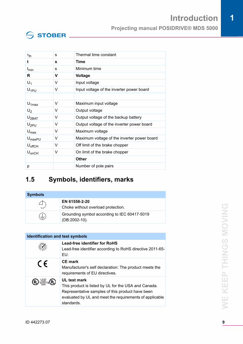
1.5 Symbols, identifiers, marks
τth s Thermal time constant
t s Time
tmin s Minimum time
R V Voltage
U1 V Input voltage
U1PU V Input voltage of the inverter power board
U1max V Maximum input voltage
U2 V Output voltage
U2BAT V Output voltage of the backup battery
U2PU V Output voltage of the inverter power board
Umax V Maximum voltage
UmaxPU V Maximum voltage of the inverter power board
UoffCH V Off limit of the brake chopper
UonCH V On limit of the brake chopper
Other
p Number of pole pairs
Symbols
EN 61558-2-20
Choke without overload protection.
Grounding symbol according to IEC 60417-5019
(DB:2002-10).
Identification and test symbols
Lead-free identifier for RoHS
Lead-free identifier according to RoHS directive 2011-65-
EU.
CE mark
Manufacturer's self declaration: The product meets the
requirements of EU directives.
UL test mark
This product is listed by UL for the USA and Canada.
Representative samples of this product have been
evaluated by UL and meet the requirements of applicable
standards.
ID 442273.07 9

Introduction
10
Projecting manual POSIDRIVE® MDS 5000
1W
E K
EE
P T
HIN
GS
MO
VIN
G
POSIDRIVE, POSIDYN and POSISwitch are trademarks of STÖBER Antriebstechnik GmbH & Co. KG.
The following names that are used in conjunction with the device, its optional equipment and its accessories
are trademarks or registered trademarks of other companies:
All other trademarks that are not listed here are the property of their respective owners.
Products that are registered as trademarks are not specially indicated in this documentation. Existing property
rights (patents, trademarks, protection of utility models) are to be observed.
UL test marks for recognized component
This component or material is recognized by UL.
Representative samples of this product have been
evaluated by UL and meet applicable requirements.
Trademarks
CANopen,CiA
CANopen and CiA are registered Community trademarks
of CAN in Automation e.V., Nuremberg, Germany.
EnDat EnDat and the EnDat logo are registered trademarks of
Dr. Johannes Heidenhain GmbH, Traunreut, Germany.
EtherCAT EtherCAT and the EtherCAT logo are registered
trademarks of Beckhoff Automation GmbH, Verl,
Germany.
PROFIBUS,PROFINET
The PROFIBUS/PROFINET logo is a registered
trademark of PROFIBUS Nutzerorganisation e. V.
Karlsruhe, Germany.
Identification and test symbols
ID 442273.07

Notes on safetyProjecting manual POSIDRIVE® MDS 5000
WE
KE
EP
TH
ING
S M
OV
ING
2
2 Notes on safetyThe devices can represent a source of danger. Therefore observe
• the safety guidelines, technical rules and regulations given in the following sections and the
• Generally applicable technical rules and regulations.
Always read the corresponding documentation as well. STÖBER ANTRIEBSTECHNIK GmbH & Co. KG shall
assume no liability for damage resulting from failure to comply with the instruction manual or relevant
regulations. This documentation is purely a production description. It does not include any guaranteed
features in terms of a warranty right. We reserve the right to make technical changes for the purpose of
improving the devices.
2.1 Component part of the product
The technical documentation is a component part of a product.
• Since the technical documentation contains important information, always keep it handy in the vicinity of
the device until the machine is disposed of.
• If the product is sold, disposed of, or rented out, always include the technical documentation with the
product.
2.2 Operation in accordance with its intended use
As defined by DIN EN 50178 (previously VDE 0160), the inverters are electrical equipment operating as
power electronics to control the flow of energy in high voltage systems. They are designed exclusively for
installation in the control cabinet with at least protection class IP54 and for supplying
• servo motors and
• asynchronous motors.
Designated use does not include connecting other electrical loads!
2.3 Risk assessment
Before the manufacturer may bring a machine onto the market, he must conduct a risk assessment according
to Machine Directive 06/42/EC. As a result, the risks associated with the use of the machine are determined.
The risk assessment is a multi-stage and iterative process. On no account can sufficient insight into the
Machine Directive be given as part of this documentation. For this reason, seek detailed information about the
norms and legal position. When installing the inverter in machines, commissioning is forbidden until it has
been determined that the machine meets the requirements of EC Directive 06/42/EC.
ID 442273.07 11

Notes on safety
12
Projecting manual POSIDRIVE® MDS 5000
2W
E K
EE
P T
HIN
GS
MO
VIN
G
2.4 Ambient conditions
The inverters are products subject to sales restrictions in accordance with IEC 61800-3. In a residential
environment this product may cause high-frequency interference. If this occurs the user may be asked to take
suitable measures to reduce it.
The inverters are not designed for use in a public low frequency network that supplies residential areas. High-
frequency interference can be expected if the inverters are used in a network of this type. The inverters are
designed exclusively for operation in TN networks. The inverters are only suitable for use in supply current
networks that are able to provide a maximally symmetrical nominal short circuit current at maximally 480 volts
according to the following table:
Install the inverter in a control cabinet in which the admissible surrounding temperature will not be exceeded.
The following applications are prohibited:
• Use in areas subject to explosion hazard
• Use in environments with harmful substances as specified by EN 60721, for example oils, acids, gases,
vapors, dust and radiation
• Use with mechanical vibration and impact loads exceeding the limits specified in the technical data in the
projecting manuals
Implementation of the following applications is only permitted after approval is obtained from STOBER:
• Use in non-stationary applications
2.5 Qualified personnel
Since the devices may harbor residual risks, all configuration, transportation, installation and commissioning
tasks including operation and disposal may only be performed by trained personnel who are aware of the
possible risks.
Personnel must have the qualifications required for the job. The following table lists examples of occupational
qualifications for the jobs:
Size Max. symmetrical nominal short-circuit current
0 and 1 5,000 A
2 5,000 A
3 10,000 A
Activity Possible occupational qualifications
Transportation and storage Worker skilled in storage logistics or comparable
training
Configuration - Graduate engineer (electro-technology or
electrical power technology)
- Technician (m/f) (electro-technology)
Installation and connection Electronics technician (m/f)
ID 442273.07

Notes on safetyProjecting manual POSIDRIVE® MDS 5000
WE
KE
EP
TH
ING
S M
OV
ING
2
In addition, the valid regulations, the legal requirements, the reference books, this technical documentation
and, in particular, the safety information contained therein must be carefully
• read,
• understood and
• complied with.
2.6 Transportation and storage
Immediately upon receipt, examine the delivery for any transportation damages. Immediately inform the
transportation company of any damages. If damages are found, do not commission the product. If the device
is not to be installed immediately, store it in a dry, dust-free room. Please see the documentation for how to
commission an inverter after it has been in storage for a year or longer.
2.7 Installation and connection
Installation and connection work are only permitted after the device has been isolated from the power!
The accessory installation instructions allow the following actions during the installation of accessories:
• The housing in the upper slot can be opened
• The housing in the bottom slot can be opened.
Opening the housing in another place or for other purposes is not permitted.
Use only copper conductors. For the line cross sections to be used, refer to DIN VDE 0298-4 or DIN EN
60204-1 Appendix D and Appendix G.
The permissible protection class is protective ground. Operation is not permitted unless the protective ground
is connected in accordance with the regulations.
Comply with the applicable instructions for installation and commissioning of motor and brakes.
Main equipment grounding markings: The main ground connections are marked "PE" or with the international
ground symbol (IEC 60417, Symbol 5019 ).
The motor must have an integrated temperature monitor with basic isolation in acc. with EN 61800-5-1 or
external motor overload protection must be used.
Commissioning (of a standard application)
- Technician (m/f) (electro-technology)
- Master electro technician (m/f)
Programming Graduate engineer (electro-technology or
electrical power technology)
Operation - Technician (m/f) (electro-technology)
- Master electro technician (m/f)
Disposal Electronics technician (m/f)
Activity Possible occupational qualifications
ID 442273.07 13

Notes on safety
14
Projecting manual POSIDRIVE® MDS 5000
2W
E K
EE
P T
HIN
GS
MO
VIN
G
Protect the device from falling parts (pieces of wire, leads, metal parts, and so on) during installation or other
tasks in the switching cabinet. Parts with conductive properties inside the inverter can cause short circuits or
device failure.
Note for UL-compliant use additionally 2.11.
2.8 Commissioning, operation and service
Remove the additional covers before commissioning so that the device will not overheat. Note the minimum
open areas specified in the projecting manuals during installation to prevent the inverter from overheating.
The inverter housing must be closed before you turn on the power supply voltage. When the power supply
voltage is turned on, hazardous voltages may be present on the connection terminals and the cables and
motor terminals connected to them. Note that the device is not reliably free of voltage simply because all the
displays are blank.
The following actions are prohibited while the supply voltage is applied
• Opening the housing,
• Connecting or disconnecting connection clamps and
• Installing accessories.
Apply the 5 safety rules in the order stated before performing any work on the machine:
1. Disconnect.Also ensure that the auxiliary circuits are disconnected.
2. Protect against being turned on again.
3. Check that voltage is not present.
4. Ground and short circuit.
5. Cover adjacent live parts.
You can carry out work on the inverter later. Repairs may only be performed by STOBER.
Send faulty devices with a fault description to:
STÖBER ANTRIEBSTECHNIK GmbH & Co. KG
Abteilung VS-EL
Kieselbronner Str.12
75177 Pforzheim
GERMANY
Information
Note that the discharge time of the DC link capacitors is up to 5 minutes. You can only determine
the absence of voltage after this time period.
ID 442273.07

Notes on safetyProjecting manual POSIDRIVE® MDS 5000
WE
KE
EP
TH
ING
S M
OV
ING
2
2.9 Disposal
Please comply with the latest national and regional regulations! Dispose of the individual parts separately
depending on their nature and currently valid regulations such as, for example:
• Electronic scrap (PCBs)
• Plastic
• Sheet metal
• Copper
• Aluminum
2.10 Residual dangers
The connected motor can be damaged with certain settings of inverters:
• Longer operation against an applied motor halting brake
• Longer operation of self-cooled motors at slow speeds
Drives can reach dangerous excess speeds (e.g., setting of high output frequencies for motors and motor
settings which are unsuitable for this). Secure the drive accordingly.
2.11 UL-compliant use
Additional information for use under UL conditions (UL – Underwriters Laboratories).
Surrounding temperature and pollution degree
The maximum surrounding temperature for UL-compliant operation is 45° C. Observe the specifications in the general data for use in an environment with pollution degree, see section
3.1.1.
Power grid type
All device types that are supplied with 480 V are designed exclusively for operation on Wye sources with 480/
277 V.
Power supply and motor overload protection
Observe the specifications in the electrical data of the inverter for this, see section 3.2.
Line fuse Observe the specifications for the UL-compliant line fuse in section 5.3.1.
Motor protection
All models of STOBER 5th generation inverters have a certified i²t model, a calculation model for thermal
monitoring of the motor. This fulfills the requirements for semiconductor motor overload protection in
accordance with the change to UL 508C dated May 2013. To activate the protective function and set it up,
ID 442273.07 15

Notes on safety
16
Projecting manual POSIDRIVE® MDS 5000
2W
E K
EE
P T
HIN
GS
MO
VIN
G
make the following parameter settings – which differ from the default values: U10 = 2:Warning and U11 =
1.00 s. This module can be used as an alternative or in addition to motor protection with temperature
monitoring as described in section 5.8.
Motor temperature sensor
All models of the 5th generation of STOBER inverters starting with HW 200 have connections for PTC
thermistors (NAT 145° C) or KTY temperature sensors (KT84-130). Observe the terminal description X2 for
proper connection, see section 5.8.
Braking resistor
If the inverters will be fitted with an externally mounted braking resistor, separate overtemperature protection
must be made available.
24 V power supply
Low-voltage circuits shall be supplied by an isolating source such that the maximum open circuit voltage
available to the circuit is not more than 28.8 V.Observe terminal description X11 for this, see section 5.4.
Lines
Use only copper conductors for an surrounding temperature of 60/75° C.
Fuses
Use a 1 A fuse (time lag) upstream from relay 1. The fuse must be approved in accordance with UL 248.Refer to the connection example of terminal description X1 for this, see section 5.5.
Branch circuit protection
An integral solid state short circuit protection does not provide branch circuit protection. If you would like to
branch the output of the inverter, branch circuit protection must be ensured in conformity with the instructions
of STOBER, the National Electrical Code and all additional applicable local regulations or equivalent
specifications.
UL test
During the UL acceptance process of STÖBER ANTRIEBSTECHNIK GmbH & Co. KG, only risks for electrical
shock and fire hazard were investigated. Aspects of functional safety were not assessed. These aspects are
assessed for STOBER by the TÜV SÜD certification authority, for example.
Information
STÖBER ANTRIEBSTECHNIK GmbH & Co. KG recommends using PTC thermistors as thermal
motor protection.
ID 442273.07

Notes on safetyProjecting manual POSIDRIVE® MDS 5000
WE
KE
EP
TH
ING
S M
OV
ING
2
2.12 Presentation of notes on safety
NOTICE
Notice
means that property damage may occur
if the stated precautionary measures are not taken.
CAUTION!
Caution
with warning triangle means that minor injury may occur
if the stated precautionary measures are not taken.
WARNING!
Warning
means that there may be a serious danger of death
if the stated precautionary measures are not taken.
DANGER!
Danger
means that serious danger of death exists
if the stated precautionary measures are not taken.
Information
refers to important information about the product or serves to emphasize a section in the
documentation to which the reader should pay special attention.
ID 442273.07 17
Technical data
18
Projecting manual POSIDRIVE® MDS 5000
3W
E K
EE
P T
HIN
GS
MO
VIN
G
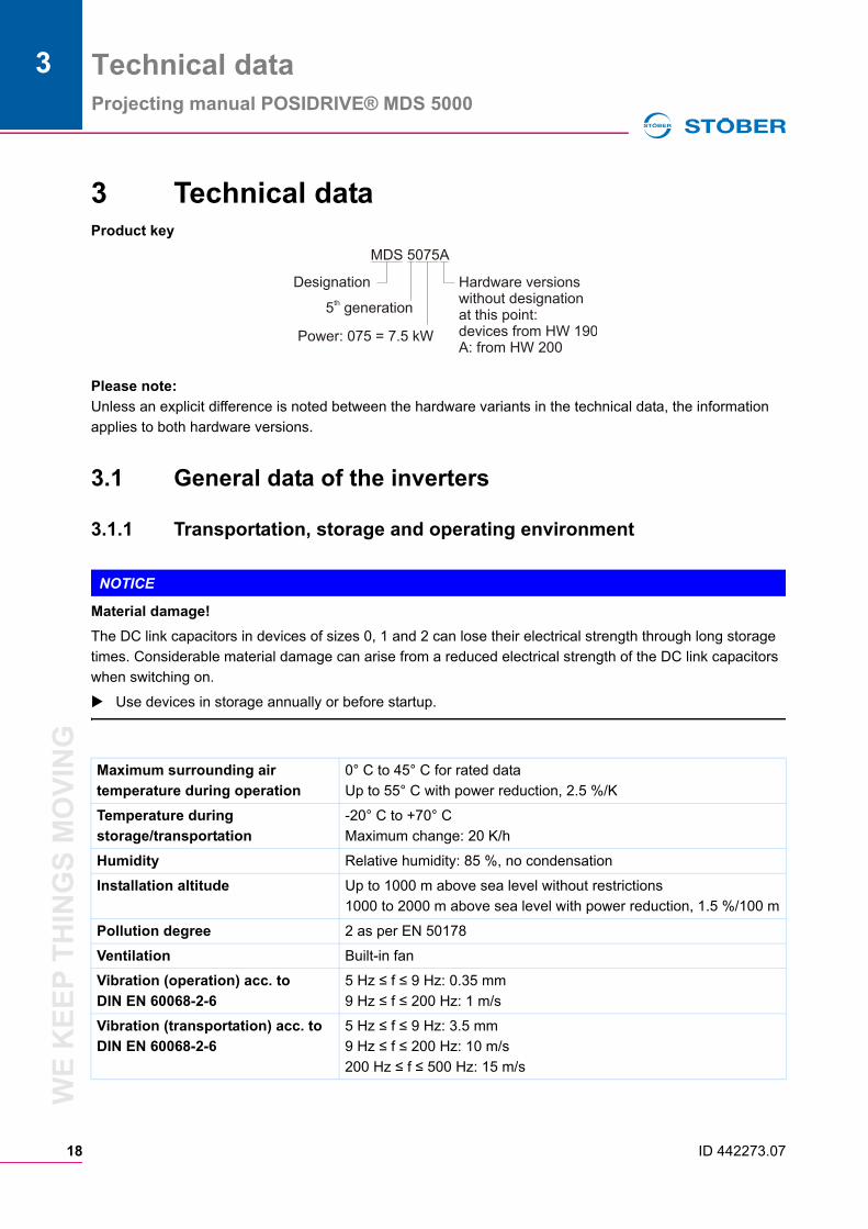
3 Technical dataProduct key
Please note:
Unless an explicit difference is noted between the hardware variants in the technical data, the information
applies to both hardware versions.
3.1 General data of the inverters
3.1.1 Transportation, storage and operating environment
NOTICE
Material damage!
The DC link capacitors in devices of sizes 0, 1 and 2 can lose their electrical strength through long storage
times. Considerable material damage can arise from a reduced electrical strength of the DC link capacitors
when switching on.
Use devices in storage annually or before startup.
Maximum surrounding air
temperature during operation
0° C to 45° C for rated data
Up to 55° C with power reduction, 2.5 %/K
Temperature during
storage/transportation
-20° C to +70° C
Maximum change: 20 K/h
Humidity Relative humidity: 85 %, no condensation
Installation altitude Up to 1000 m above sea level without restrictions
1000 to 2000 m above sea level with power reduction, 1.5 %/100 m
Pollution degree 2 as per EN 50178
Ventilation Built-in fan
Vibration (operation) acc. to
DIN EN 60068-2-6
5 Hz ≤ f ≤ 9 Hz: 0.35 mm
9 Hz ≤ f ≤ 200 Hz: 1 m/s
Vibration (transportation) acc. to
DIN EN 60068-2-6
5 Hz ≤ f ≤ 9 Hz: 3.5 mm
9 Hz ≤ f ≤ 200 Hz: 10 m/s
200 Hz ≤ f ≤ 500 Hz: 15 m/s
MDS 5075A
Designation
Power: 075 = 7.5 kW
5 generationth
Hardware versionswithout designationat this point:devices from HW 190A: from HW 200
ID 442273.07

Technical dataProjecting manual POSIDRIVE® MDS 5000
WE
KE
EP
TH
ING
S M
OV
ING
3
3.1.2 Device features
3.1.3 Weight
If you order an inverter with accessory parts, the weight increases by the following amounts:
• Accessory parts for higher option (fieldbus): 0.1 kg
• Accessory parts for lower option (terminals): 0.2 kg
Protection rating IP20
Interference suppression EN 61800-3, interference emission, class C3
High-voltage category III as per EN 61800-5-1
Device Weight
Without Packaging [kg] With Packaging [kg]
MDS 5007
2.2 3.2MDS 5008
MDS 5015
MDS 50403.8 5.1
MDS 5075
MDS 51105.0 6.1
MDS 5150
MDS 5220 11.8 13.6
MDS 537013.2 15.0
MDS 5450
ID 442273.07 19
Technical data
20
Projecting manual POSIDRIVE® MDS 5000
3W
E K
EE
P T
HIN
GS
MO
VIN
G
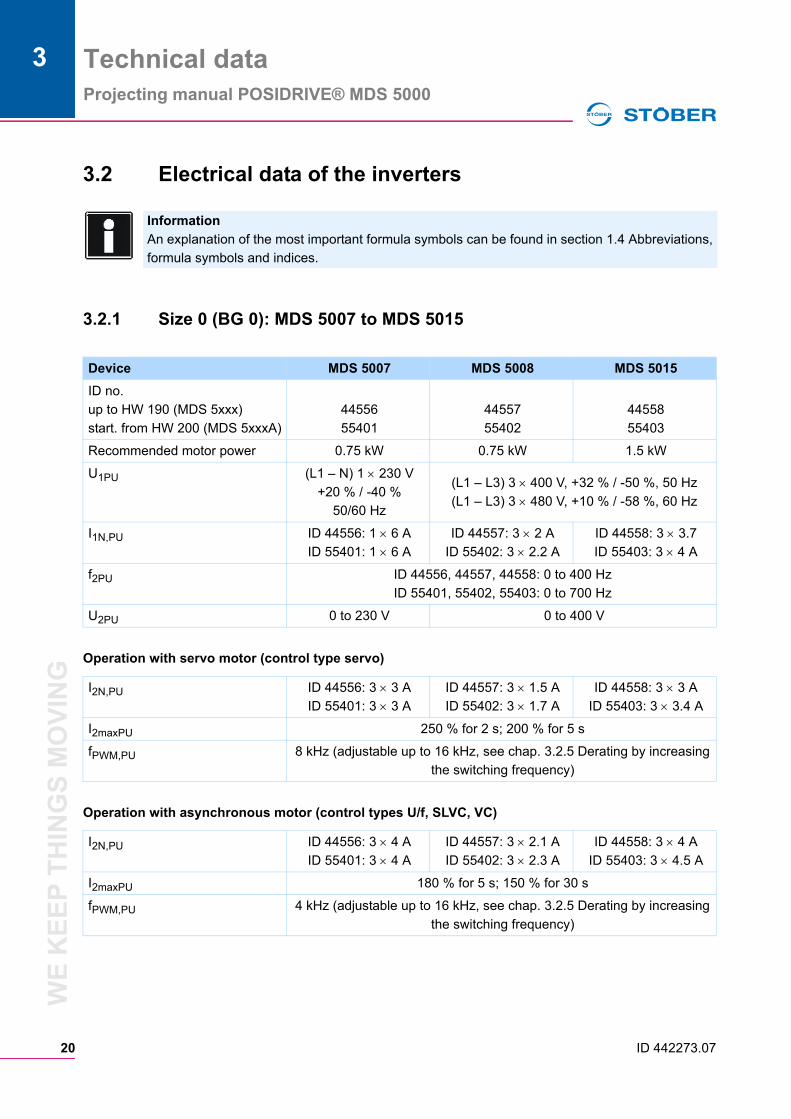
3.2 Electrical data of the inverters
3.2.1 Size 0 (BG 0): MDS 5007 to MDS 5015
Operation with servo motor (control type servo)
Operation with asynchronous motor (control types U/f, SLVC, VC)
Information
An explanation of the most important formula symbols can be found in section 1.4 Abbreviations,
formula symbols and indices.
Device MDS 5007 MDS 5008 MDS 5015
ID no.
up to HW 190 (MDS 5xxx)
start. from HW 200 (MDS 5xxxA)
44556
55401
44557
55402
44558
55403
Recommended motor power 0.75 kW 0.75 kW 1.5 kW
U1PU (L1 – N) 1 230 V
+20 % / -40 %
50/60 Hz
(L1 – L3) 3 400 V, +32 % / -50 %, 50 Hz
(L1 – L3) 3 480 V, +10 % / -58 %, 60 Hz
I1N,PU ID 44556: 1 6 A
ID 55401: 1 6 A
ID 44557: 3 2 A
ID 55402: 3 2.2 A
ID 44558: 3 3.7
ID 55403: 3 4 A
f2PU ID 44556, 44557, 44558: 0 to 400 Hz
ID 55401, 55402, 55403: 0 to 700 Hz
U2PU 0 to 230 V 0 to 400 V
I2N,PU ID 44556: 3 3 A
ID 55401: 3 3 A
ID 44557: 3 1.5 A
ID 55402: 3 1.7 A
ID 44558: 3 3 A
ID 55403: 3 3.4 A
I2maxPU 250 % for 2 s; 200 % for 5 s
fPWM,PU 8 kHz (adjustable up to 16 kHz, see chap. 3.2.5 Derating by increasing
the switching frequency)
I2N,PU ID 44556: 3 4 A
ID 55401: 3 4 A
ID 44557: 3 2.1 A
ID 55402: 3 2.3 A
ID 44558: 3 4 A
ID 55403: 3 4.5 A
I2maxPU 180 % for 5 s; 150 % for 30 s
fPWM,PU 4 kHz (adjustable up to 16 kHz, see chap. 3.2.5 Derating by increasing
the switching frequency)
ID 442273.07
Technical dataProjecting manual POSIDRIVE® MDS 5000
WE
KE
EP
TH
ING
S M
OV
ING
3
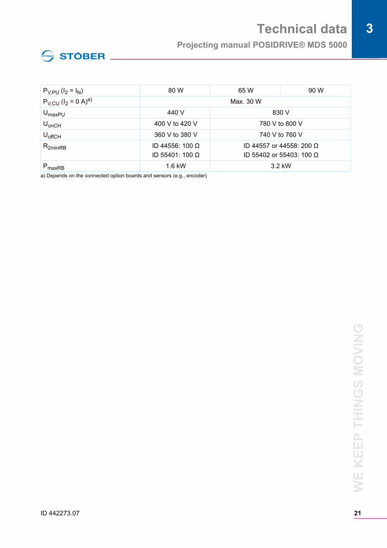
PV,PU (I2 = IN) 80 W 65 W 90 W
PV,CU (I2 = 0 A)a)
a) Depends on the connected option boards and sensors (e.g., encoder)
Max. 30 W
UmaxPU 440 V 830 V
UonCH 400 V to 420 V 780 V to 800 V
UoffCH 360 V to 380 V 740 V to 760 V
R2minRB ID 44556: 100 Ω
ID 55401: 100 Ω
ID 44557 or 44558: 200 Ω
ID 55402 or 55403: 100 Ω
PmaxRB 1.6 kW 3.2 kW
ID 442273.07 21
Technical data
22
Projecting manual POSIDRIVE® MDS 5000
3W
E K
EE
P T
HIN
GS
MO
VIN
G
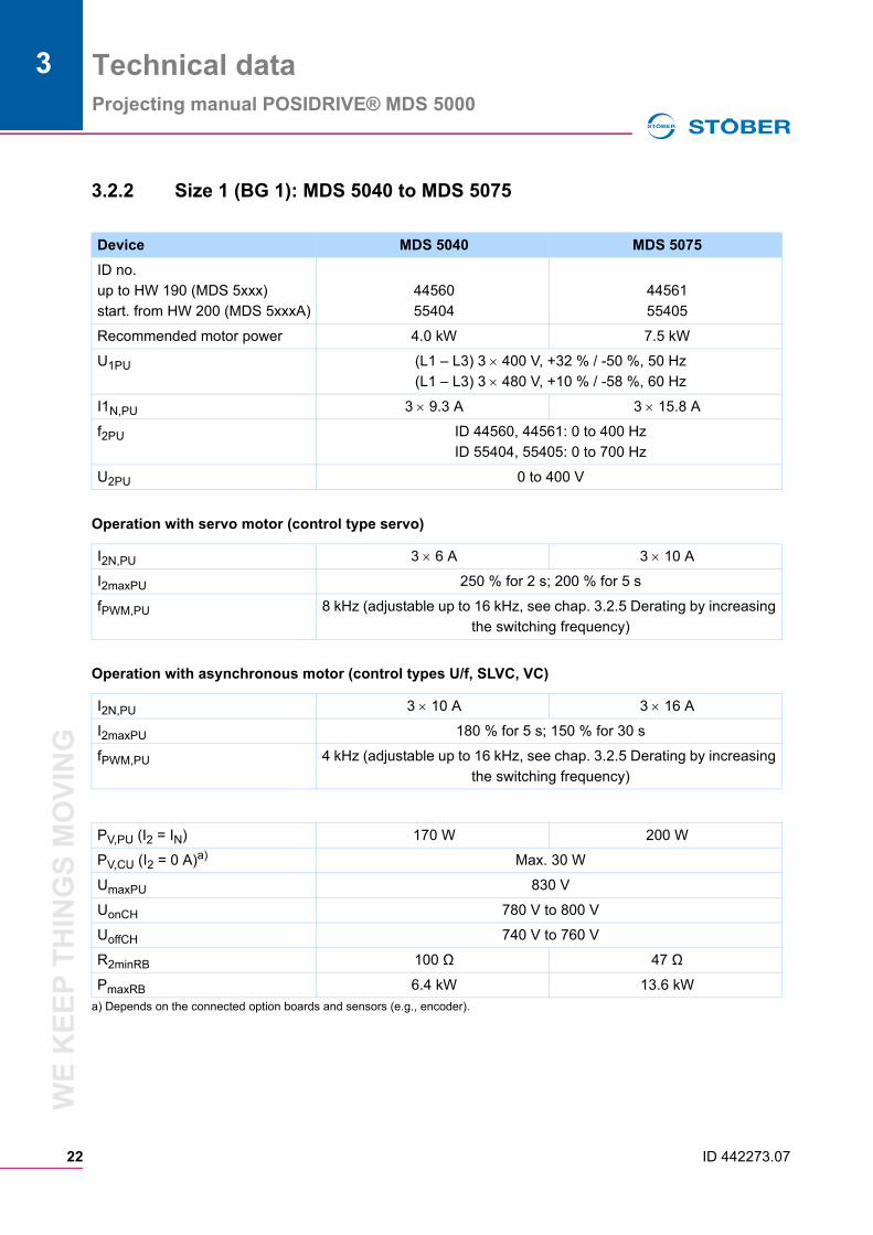
3.2.2 Size 1 (BG 1): MDS 5040 to MDS 5075
Operation with servo motor (control type servo)
Operation with asynchronous motor (control types U/f, SLVC, VC)
Device MDS 5040 MDS 5075
ID no.
up to HW 190 (MDS 5xxx)
start. from HW 200 (MDS 5xxxA)
44560
55404
44561
55405
Recommended motor power 4.0 kW 7.5 kW
U1PU (L1 – L3) 3 400 V, +32 % / -50 %, 50 Hz
(L1 – L3) 3 480 V, +10 % / -58 %, 60 Hz
I1N,PU 3 9.3 A 3 15.8 A
f2PU ID 44560, 44561: 0 to 400 Hz
ID 55404, 55405: 0 to 700 Hz
U2PU 0 to 400 V
I2N,PU 3 6 A 3 10 A
I2maxPU 250 % for 2 s; 200 % for 5 s
fPWM,PU 8 kHz (adjustable up to 16 kHz, see chap. 3.2.5 Derating by increasing
the switching frequency)
I2N,PU 3 10 A 3 16 A
I2maxPU 180 % for 5 s; 150 % for 30 s
fPWM,PU 4 kHz (adjustable up to 16 kHz, see chap. 3.2.5 Derating by increasing
the switching frequency)
PV,PU (I2 = IN) 170 W 200 W
PV,CU (I2 = 0 A)a)
a) Depends on the connected option boards and sensors (e.g., encoder).
Max. 30 W
UmaxPU 830 V
UonCH 780 V to 800 V
UoffCH 740 V to 760 V
R2minRB 100 Ω 47 Ω
PmaxRB 6.4 kW 13.6 kW
ID 442273.07
Technical dataProjecting manual POSIDRIVE® MDS 5000
WE
KE
EP
TH
ING
S M
OV
ING
3
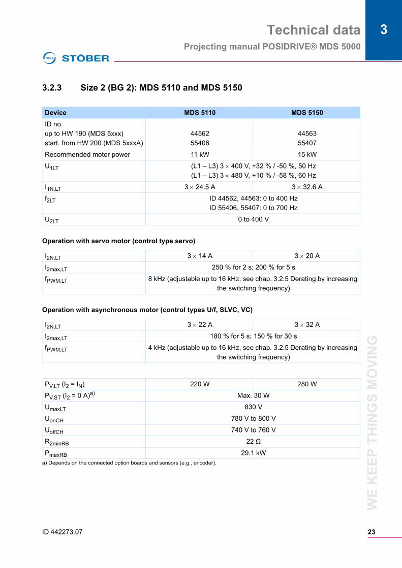
3.2.3 Size 2 (BG 2): MDS 5110 and MDS 5150
Operation with servo motor (control type servo)
Operation with asynchronous motor (control types U/f, SLVC, VC)
Device MDS 5110 MDS 5150
ID no.
up to HW 190 (MDS 5xxx)
start. from HW 200 (MDS 5xxxA)
44562
55406
44563
55407
Recommended motor power 11 kW 15 kW
U1LT (L1 – L3) 3 400 V, +32 % / -50 %, 50 Hz
(L1 – L3) 3 480 V, +10 % / -58 %, 60 Hz
I1N,LT 3 24.5 A 3 32.6 A
f2LT ID 44562, 44563: 0 to 400 Hz
ID 55406, 55407: 0 to 700 Hz
U2LT 0 to 400 V
I2N,LT 3 14 A 3 20 A
I2max,LT 250 % for 2 s; 200 % for 5 s
fPWM,LT 8 kHz (adjustable up to 16 kHz, see chap. 3.2.5 Derating by increasing
the switching frequency)
I2N,LT 3 22 A 3 32 A
I2max,LT 180 % for 5 s; 150 % for 30 s
fPWM,LT 4 kHz (adjustable up to 16 kHz, see chap. 3.2.5 Derating by increasing
the switching frequency)
PV,LT (I2 = IN) 220 W 280 W
PV,ST (I2 = 0 A)a)
a) Depends on the connected option boards and sensors (e.g., encoder).
Max. 30 W
UmaxLT 830 V
UonCH 780 V to 800 V
UoffCH 740 V to 760 V
R2minRB 22 Ω
PmaxRB 29.1 kW
ID 442273.07 23
Technical data
24
Projecting manual POSIDRIVE® MDS 5000
3W
E K
EE
P T
HIN
GS
MO
VIN
G
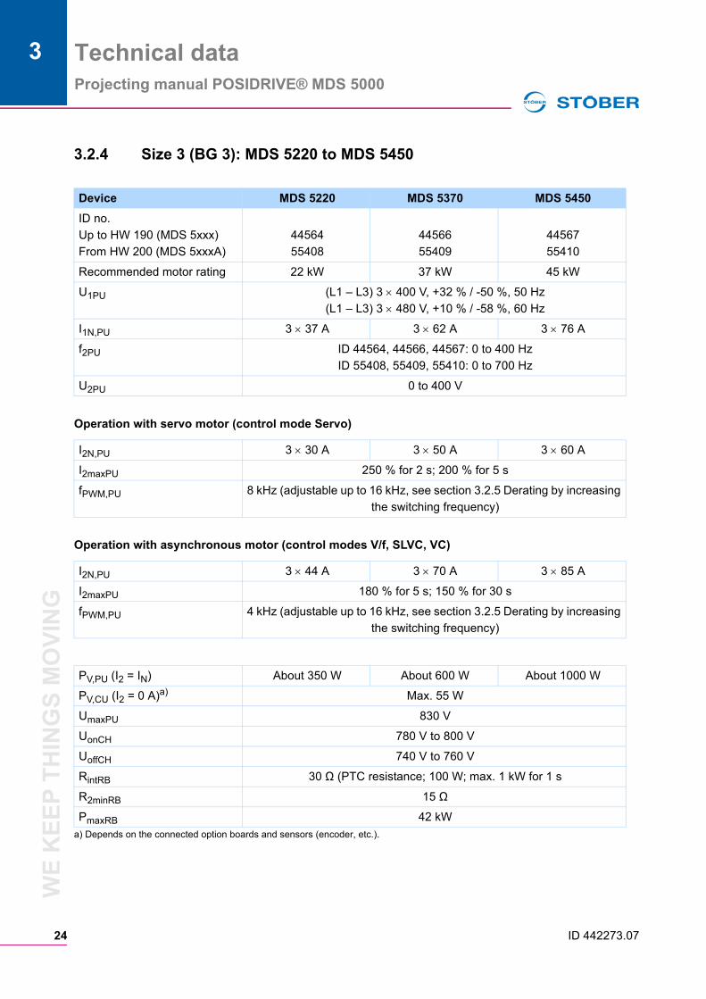
3.2.4 Size 3 (BG 3): MDS 5220 to MDS 5450
Operation with servo motor (control mode Servo)
Operation with asynchronous motor (control modes V/f, SLVC, VC)
Device MDS 5220 MDS 5370 MDS 5450
ID no.
Up to HW 190 (MDS 5xxx)
From HW 200 (MDS 5xxxA)
44564
55408
44566
55409
44567
55410
Recommended motor rating 22 kW 37 kW 45 kW
U1PU (L1 – L3) 3 400 V, +32 % / -50 %, 50 Hz
(L1 – L3) 3 480 V, +10 % / -58 %, 60 Hz
I1N,PU 3 37 A 3 62 A 3 76 A
f2PU ID 44564, 44566, 44567: 0 to 400 Hz
ID 55408, 55409, 55410: 0 to 700 Hz
U2PU 0 to 400 V
I2N,PU 3 30 A 3 50 A 3 60 A
I2maxPU 250 % for 2 s; 200 % for 5 s
fPWM,PU 8 kHz (adjustable up to 16 kHz, see section 3.2.5 Derating by increasing
the switching frequency)
I2N,PU 3 44 A 3 70 A 3 85 A
I2maxPU 180 % for 5 s; 150 % for 30 s
fPWM,PU 4 kHz (adjustable up to 16 kHz, see section 3.2.5 Derating by increasing
the switching frequency)
PV,PU (I2 = IN) About 350 W About 600 W About 1000 W
PV,CU (I2 = 0 A)a)
a) Depends on the connected option boards and sensors (encoder, etc.).
Max. 55 W
UmaxPU 830 V
UonCH 780 V to 800 V
UoffCH 740 V to 760 V
RintRB 30 Ω (PTC resistance; 100 W; max. 1 kW for 1 s
R2minRB 15 Ω
PmaxRB 42 kW
ID 442273.07
Technical dataProjecting manual POSIDRIVE® MDS 5000
WE
KE
EP
TH
ING
S M
OV
ING
3
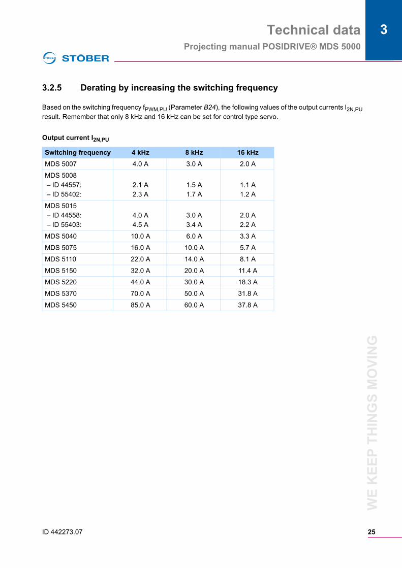
3.2.5 Derating by increasing the switching frequency
Based on the switching frequency fPWM,PU (Parameter B24), the following values of the output currents I2N,PU
result. Remember that only 8 kHz and 16 kHz can be set for control type servo.
Output current I2N,PU
Switching frequency 4 kHz 8 kHz 16 kHz
MDS 5007 4.0 A 3.0 A 2.0 A
MDS 5008
– ID 44557:
– ID 55402:
2.1 A
2.3 A
1.5 A
1.7 A
1.1 A
1.2 A
MDS 5015
– ID 44558:
– ID 55403:
4.0 A
4.5 A
3.0 A
3.4 A
2.0 A
2.2 A
MDS 5040 10.0 A 6.0 A 3.3 A
MDS 5075 16.0 A 10.0 A 5.7 A
MDS 5110 22.0 A 14.0 A 8.1 A
MDS 5150 32.0 A 20.0 A 11.4 A
MDS 5220 44.0 A 30.0 A 18.3 A
MDS 5370 70.0 A 50.0 A 31.8 A
MDS 5450 85.0 A 60.0 A 37.8 A
ID 442273.07 25
Technical data
26
Projecting manual POSIDRIVE® MDS 5000
3W
E K
EE
P T
HIN
GS
MO
VIN
G
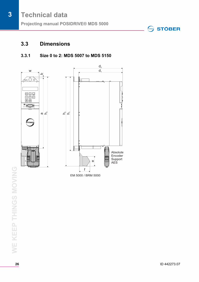
3.3 Dimensions
3.3.1 Size 0 to 2: MDS 5007 to MDS 5150
w
ba h 1h 2h 3
d1
d2
f
eESC
I/O
EM 5000 / BRM 5000
AbsoluteEncoderSupportAES
ID 442273.07
Technical dataProjecting manual POSIDRIVE® MDS 5000
WE
KE
EP
TH
ING
S M
OV
ING
3
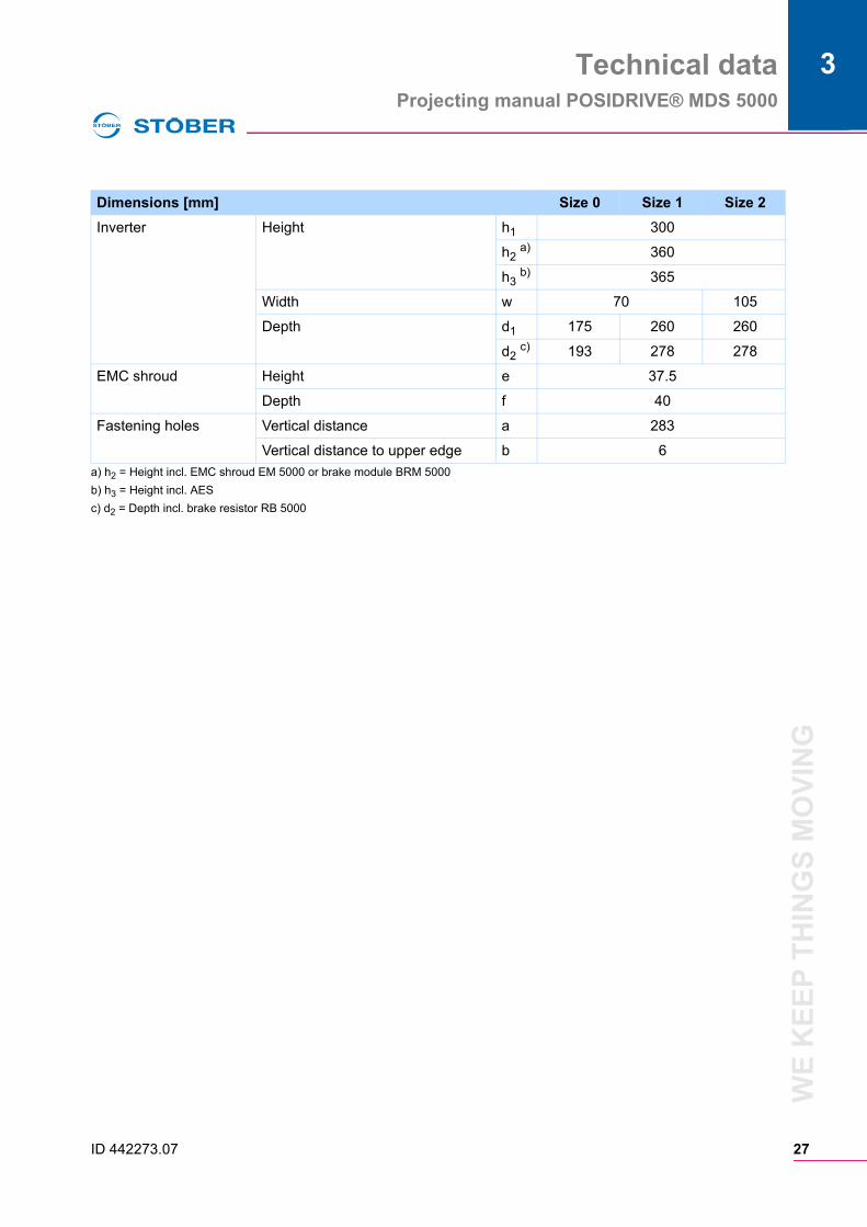
Dimensions [mm] Size 0 Size 1 Size 2
Inverter Height h1 300
h2 a)
a) h2 = Height incl. EMC shroud EM 5000 or brake module BRM 5000
360
h3 b)
b) h3 = Height incl. AES
365
Width w 70 105
Depth d1 175 260 260
d2 c)
c) d2 = Depth incl. brake resistor RB 5000
193 278 278
EMC shroud Height e 37.5
Depth f 40
Fastening holes Vertical distance a 283
Vertical distance to upper edge b 6
ID 442273.07 27
Technical data
28
Projecting manual POSIDRIVE® MDS 5000
3W
E K
EE
P T
HIN
GS
MO
VIN
G
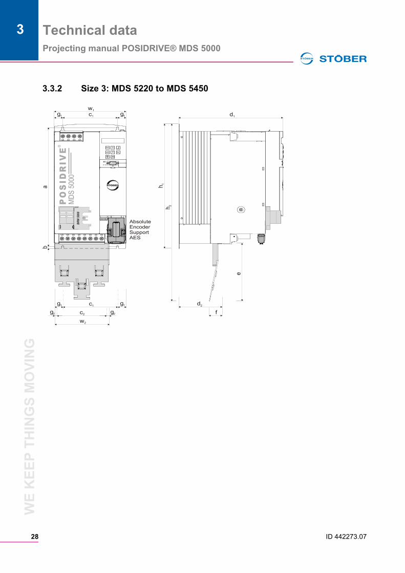
3.3.2 Size 3: MDS 5220 to MDS 5450
ID 442273.07
Technical dataProjecting manual POSIDRIVE® MDS 5000
WE
KE
EP
TH
ING
S M
OV
ING
3
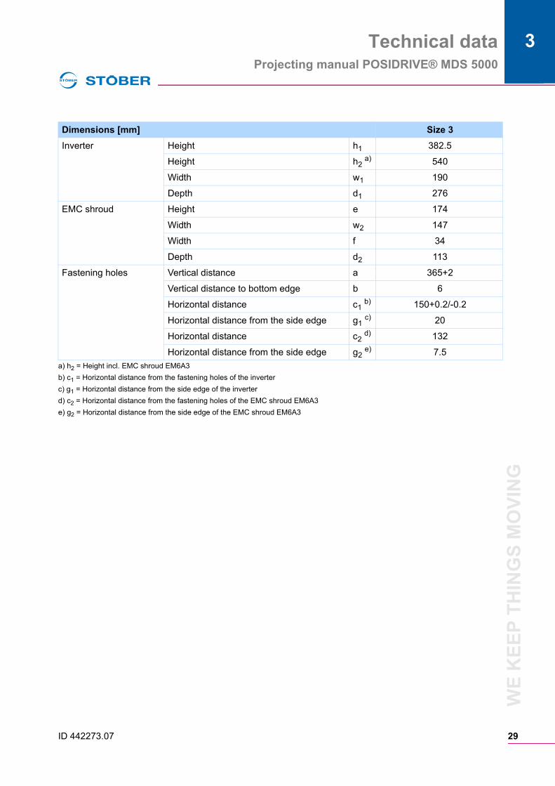
Dimensions [mm] Size 3
Inverter Height h1 382.5
Height h2 a)
a) h2 = Height incl. EMC shroud EM6A3
540
Width w1 190
Depth d1 276
EMC shroud Height e 174
Width w2 147
Width f 34
Depth d2 113
Fastening holes Vertical distance a 365+2
Vertical distance to bottom edge b 6
Horizontal distance c1 b)
b) c1 = Horizontal distance from the fastening holes of the inverter
150+0.2/-0.2
Horizontal distance from the side edge g1 c)
c) g1 = Horizontal distance from the side edge of the inverter
20
Horizontal distance c2 d)
d) c2 = Horizontal distance from the fastening holes of the EMC shroud EM6A3
132
Horizontal distance from the side edge g2 e)
e) g2 = Horizontal distance from the side edge of the EMC shroud EM6A3
7.5
ID 442273.07 29
Technical data
30
Projecting manual POSIDRIVE® MDS 5000
3W
E K
EE
P T
HIN
GS
MO
VIN
G
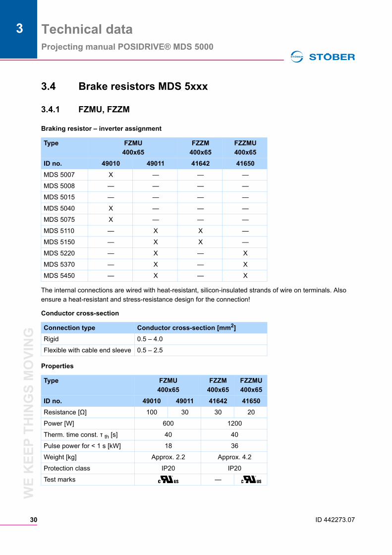
3.4 Brake resistors MDS 5xxx
3.4.1 FZMU, FZZM
Braking resistor – inverter assignment
The internal connections are wired with heat-resistant, silicon-insulated strands of wire on terminals. Also
ensure a heat-resistant and stress-resistance design for the connection!
Conductor cross-section
Properties
Type FZMU
400x65
FZZM
400x65
FZZMU
400x65
ID no. 49010 49011 41642 41650
MDS 5007 X — — —
MDS 5008 — — — —
MDS 5015 — — — —
MDS 5040 X — — —
MDS 5075 X — — —
MDS 5110 — X X —
MDS 5150 — X X —
MDS 5220 — X — X
MDS 5370 — X — X
MDS 5450 — X — X
Connection type Conductor cross-section [mm2]
Rigid 0.5 – 4.0
Flexible with cable end sleeve 0.5 – 2.5
Type FZMU
400x65
FZZM
400x65
FZZMU
400x65
ID no. 49010 49011 41642 41650
Resistance [Ω] 100 30 30 20
Power [W] 600 1200
Therm. time const. τ th [s] 40 40
Pulse power for < 1 s [kW] 18 36
Weight [kg] Approx. 2.2 Approx. 4.2
Protection class IP20 IP20
Test marks —
ID 442273.07
Technical dataProjecting manual POSIDRIVE® MDS 5000
WE
KE
EP
TH
ING
S M
OV
ING
3
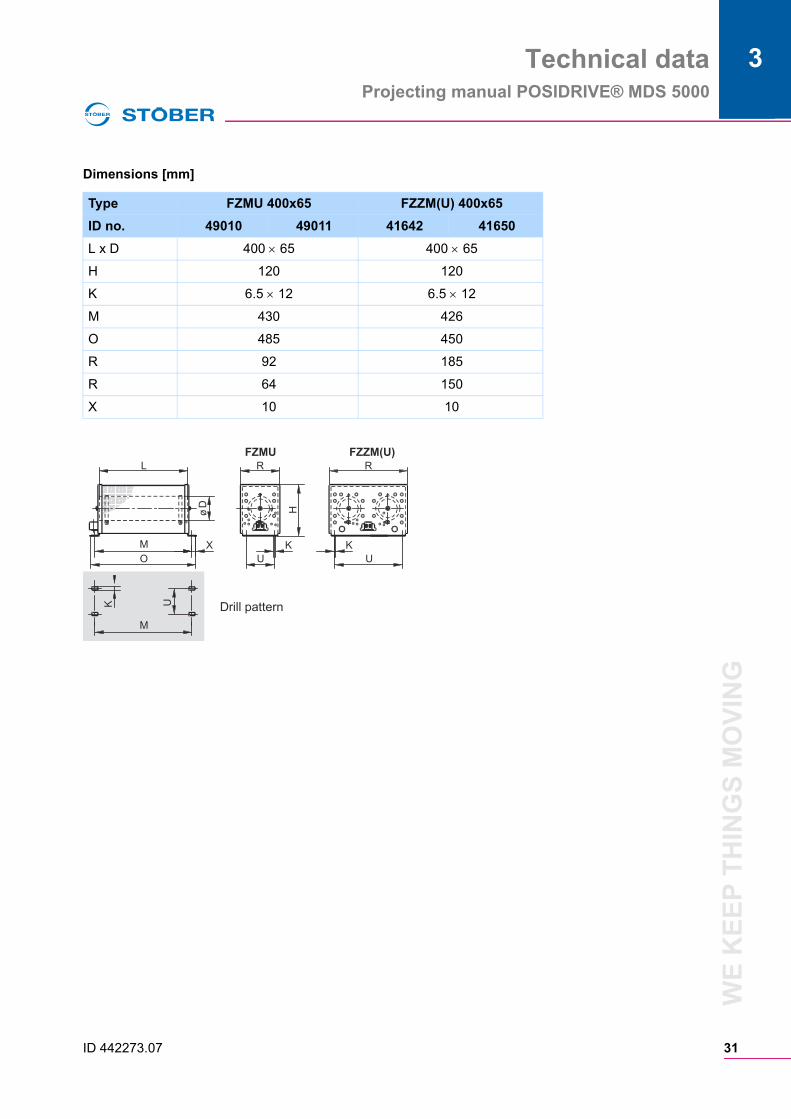
Dimensions [mm]
Type FZMU 400x65 FZZM(U) 400x65
ID no. 49010 49011 41642 41650
L x D 400 65 400 65
H 120 120
K 6.5 12 6.5 12
M 430 426
O 485 450
R 92 185
R 64 150
X 10 10
R RFZMU FZZM(U)
L
U UOK KM
K U
M
X
HøD
Drill pattern
ID 442273.07 31
Technical data
32
Projecting manual POSIDRIVE® MDS 5000
3W
E K
EE
P T
HIN
GS
MO
VIN
G
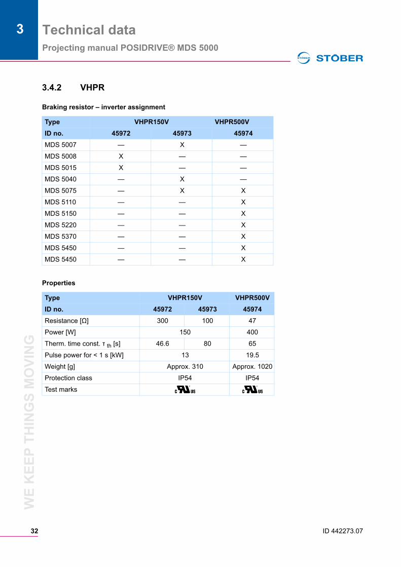
3.4.2 VHPR
Braking resistor – inverter assignment
Properties
Type VHPR150V VHPR500V
ID no. 45972 45973 45974
MDS 5007 — X —
MDS 5008 X — —
MDS 5015 X — —
MDS 5040 — X —
MDS 5075 — X X
MDS 5110 — — X
MDS 5150 — — X
MDS 5220 — — X
MDS 5370 — — X
MDS 5450 — — X
MDS 5450 — — X
Type VHPR150V VHPR500V
ID no. 45972 45973 45974
Resistance [Ω] 300 100 47
Power [W] 150 400
Therm. time const. τ th [s] 46.6 80 65
Pulse power for < 1 s [kW] 13 19.5
Weight [g] Approx. 310 Approx. 1020
Protection class IP54 IP54
Test marks
ID 442273.07
Technical dataProjecting manual POSIDRIVE® MDS 5000
WE
KE
EP
TH
ING
S M
OV
ING
3
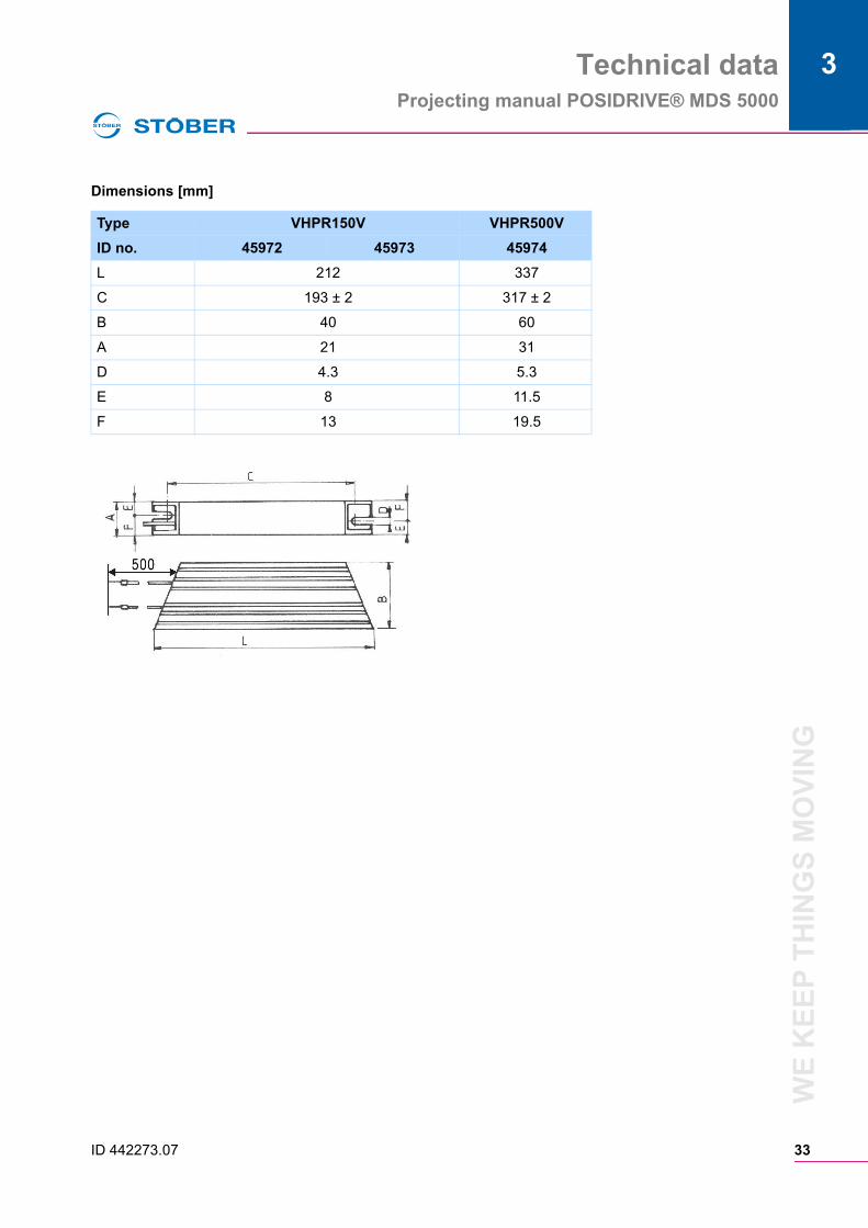
Dimensions [mm]
Type VHPR150V VHPR500V
ID no. 45972 45973 45974
L 212 337
C 193 ± 2 317 ± 2
B 40 60
A 21 31
D 4.3 5.3
E 8 11.5
F 13 19.5
ID 442273.07 33

Technical data
34
Projecting manual POSIDRIVE® MDS 5000
3W
E K
EE
P T
HIN
GS
MO
VIN
G
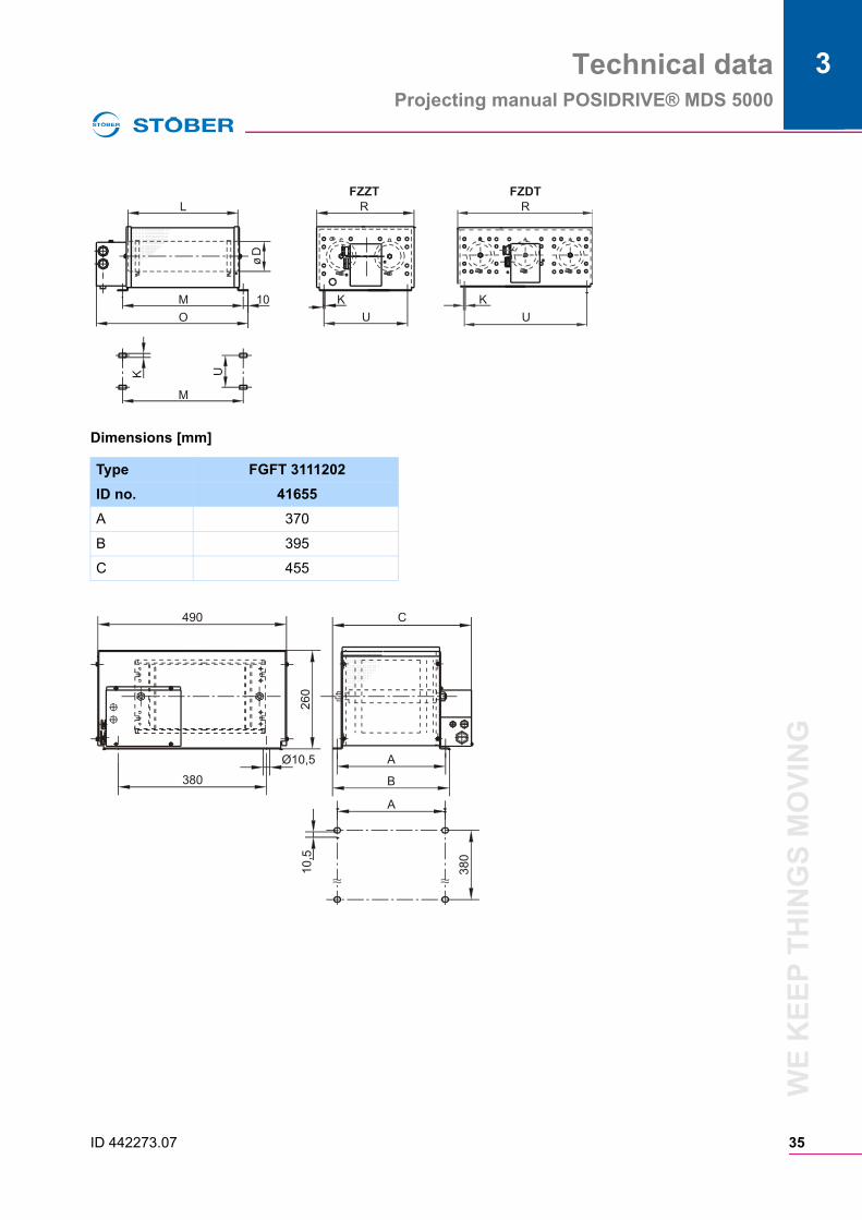
3.4.3 FZZT, FZDT and FGFT
Braking resistor – inverter assignment
Properties
Dimensions [mm]
Type FZZT 400x65 FZDT 500x65 FGFT 3111202
ID no. 41651 41653 41655
MDS 5220 X X X
MDS 5370 X X X
MDS 5450 X X X
Type FZZT 40065 FZDT 50065 FGFT 3111202
ID no. 41651 41653 41655
Resistance [Ω] 20 20 20
Power [W] 1200 2500 6000
Thermal time constant τ th 30 30 20
Weight [kg] Approx. 4.6 Approx. 7.8 Approx. 13
Protection class IP20 IP20 IP20
Type FZZT 40065 FZDT 50065
ID no. 41651 41653
L D 400 65 500 65
H 120 120
K 6.5 12 6.5 12
M 426 526
O 506 606
R 185 275
R 150 240
ID 442273.07
Technical dataProjecting manual POSIDRIVE® MDS 5000
WE
KE
EP
TH
ING
S M
OV
ING
3
Dimensions [mm]
Type FGFT 3111202
ID no. 41655
A 370
B 395
C 455
R RLFZZT FZDT
U UO
K K
K U
M
M
10
øD
490 C
A
B
Ø10,5
380
26
0
A
10,5
380
ID 442273.07 35
Technical data
36
Projecting manual POSIDRIVE® MDS 5000
3W
E K
EE
P T
HIN
GS
MO
VIN
G
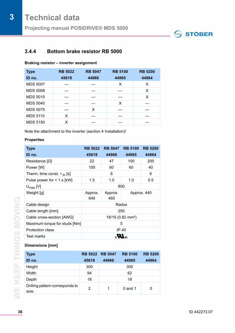
3.4.4 Bottom brake resistor RB 5000
Braking resistor – inverter assignment
Note the attachment to the inverter (section 4 Installation)!
Properties
Dimensions [mm]
Type RB 5022 RB 5047 RB 5100 RB 5200
ID no. 45618 44966 44965 44964
MDS 5007 — — X X
MDS 5008 — — — X
MDS 5015 — — — X
MDS 5040 — — X —
MDS 5075 — X — —
MDS 5110 X — — —
MDS 5150 X — — —
Type RB 5022 RB 5047 RB 5100 RB 5200
ID no. 45618 44966 44965 44964
Resistance [Ω] 22 47 100 200
Power [W] 100 60 60 40
Therm. time const. τ th [s] 8 6
Pulse power for < 1 s [kW] 1.5 1.0 1.0 0.5
Umax [V] 800
Weight [g] Approx.
640
Approx.
460
Approx. 440
Cable design Radox
Cable length [mm] 250
Cable cross-section [AWG] 18/19 (0.82 mm²)
Maximum torque for studs [Nm] 5
Protection class IP 40
Test marks
Type RB 5022 RB 5047 RB 5100 RB 5200
ID no. 45618 44966 44965 44964
Height 300 300
Width 94 62
Depth 18 18
Drilling pattern corresponds to
size:2 1 0 and 1 0
ID 442273.07
Technical dataProjecting manual POSIDRIVE® MDS 5000
WE
KE
EP
TH
ING
S M
OV
ING
3
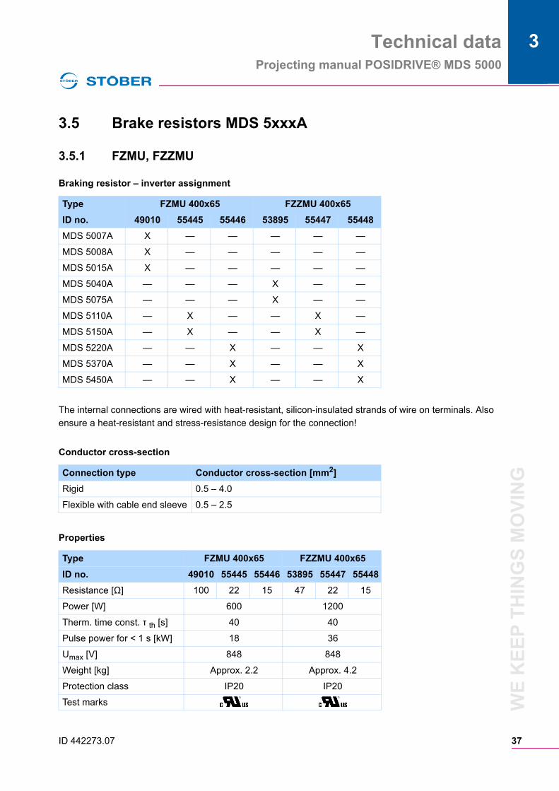
3.5 Brake resistors MDS 5xxxA
3.5.1 FZMU, FZZMU
Braking resistor – inverter assignment
The internal connections are wired with heat-resistant, silicon-insulated strands of wire on terminals. Also
ensure a heat-resistant and stress-resistance design for the connection!
Conductor cross-section
Properties
Type FZMU 400x65 FZZMU 400x65
ID no. 49010 55445 55446 53895 55447 55448
MDS 5007A X — — — — —
MDS 5008A X — — — — —
MDS 5015A X — — — — —
MDS 5040A — — — X — —
MDS 5075A — — — X — —
MDS 5110A — X — — X —
MDS 5150A — X — — X —
MDS 5220A — — X — — X
MDS 5370A — — X — — X
MDS 5450A — — X — — X
Connection type Conductor cross-section [mm2]
Rigid 0.5 – 4.0
Flexible with cable end sleeve 0.5 – 2.5
Type FZMU 400x65 FZZMU 400x65
ID no. 49010 55445 55446 53895 55447 55448
Resistance [Ω] 100 22 15 47 22 15
Power [W] 600 1200
Therm. time const. τ th [s] 40 40
Pulse power for < 1 s [kW] 18 36
Umax [V] 848 848
Weight [kg] Approx. 2.2 Approx. 4.2
Protection class IP20 IP20
Test marks
ID 442273.07 37
Technical data
38
Projecting manual POSIDRIVE® MDS 5000
3W
E K
EE
P T
HIN
GS
MO
VIN
G
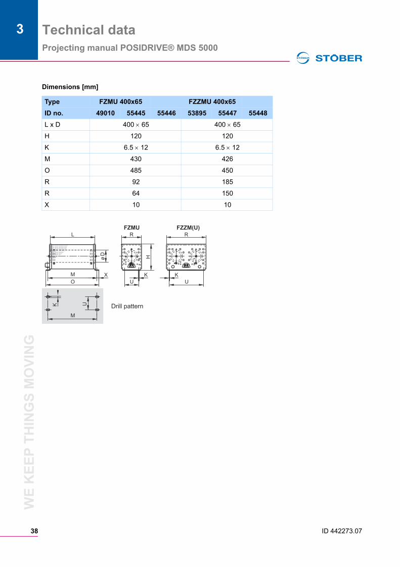
Dimensions [mm]
Type FZMU 400x65 FZZMU 400x65
ID no. 49010 55445 55446 53895 55447 55448
L x D 400 65 400 65
H 120 120
K 6.5 12 6.5 12
M 430 426
O 485 450
R 92 185
R 64 150
X 10 10
R RFZMU FZZM(U)
L
U UOK KM
K U
M
X
HøD
Drill pattern
ID 442273.07
Technical dataProjecting manual POSIDRIVE® MDS 5000
WE
KE
EP
TH
ING
S M
OV
ING
3
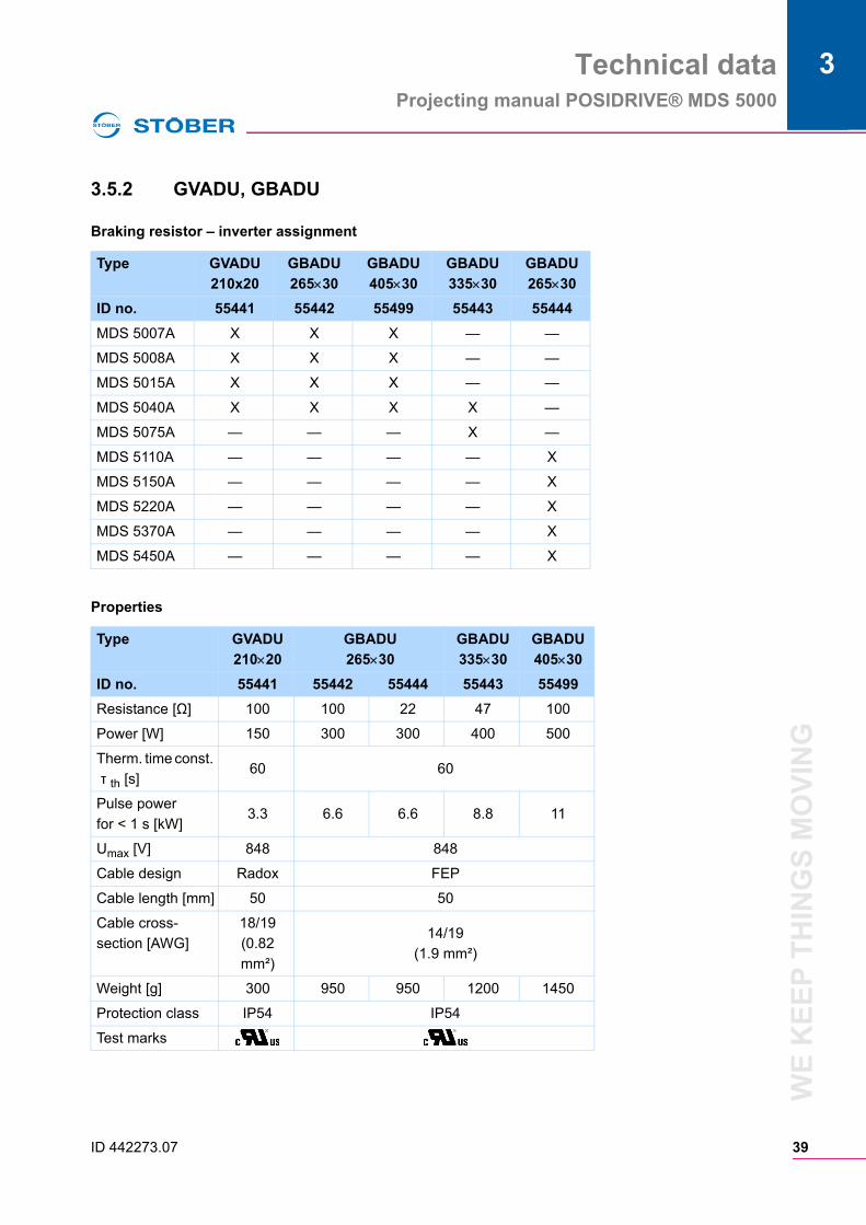
3.5.2 GVADU, GBADU
Braking resistor – inverter assignment
Properties
Type GVADU
210x20
GBADU
26530
GBADU
40530
GBADU
33530
GBADU
26530
ID no. 55441 55442 55499 55443 55444
MDS 5007A X X X — —
MDS 5008A X X X — —
MDS 5015A X X X — —
MDS 5040A X X X X —
MDS 5075A — — — X —
MDS 5110A — — — — X
MDS 5150A — — — — X
MDS 5220A — — — — X
MDS 5370A — — — — X
MDS 5450A — — — — X
Type GVADU
21020
GBADU
26530
GBADU
33530
GBADU
40530
ID no. 55441 55442 55444 55443 55499
Resistance [Ω] 100 100 22 47 100
Power [W] 150 300 300 400 500
Therm. time const. τ th [s]
60 60
Pulse power for < 1 s [kW]
3.3 6.6 6.6 8.8 11
Umax [V] 848 848
Cable design Radox FEP
Cable length [mm] 50 50
Cable cross-
section [AWG]
18/19
(0.82
mm²)
14/19
(1.9 mm²)
Weight [g] 300 950 950 1200 1450
Protection class IP54 IP54
Test marks
ID 442273.07 39
Technical data
40
Projecting manual POSIDRIVE® MDS 5000
3W
E K
EE
P T
HIN
GS
MO
VIN
G
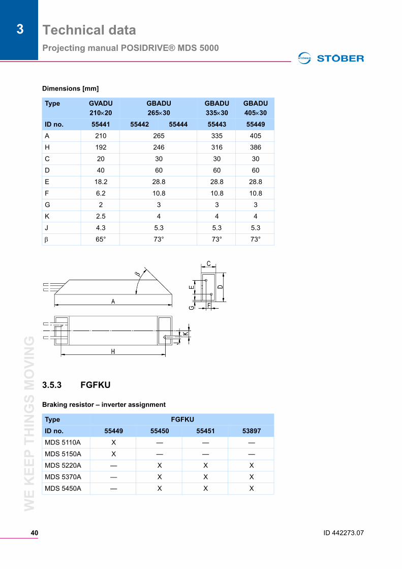
Dimensions [mm]
3.5.3 FGFKU
Braking resistor – inverter assignment
Type GVADU
21020
GBADU
26530
GBADU
33530
GBADU
40530
ID no. 55441 55442 55444 55443 55449
A 210 265 335 405
H 192 246 316 386
C 20 30 30 30
D 40 60 60 60
E 18.2 28.8 28.8 28.8
F 6.2 10.8 10.8 10.8
G 2 3 3 3
K 2.5 4 4 4
J 4.3 5.3 5.3 5.3
65° 73° 73° 73°
Type FGFKU
ID no. 55449 55450 55451 53897
MDS 5110A X — — —
MDS 5150A X — — —
MDS 5220A — X X X
MDS 5370A — X X X
MDS 5450A — X X X
ID 442273.07
Technical dataProjecting manual POSIDRIVE® MDS 5000
WE
KE
EP
TH
ING
S M
OV
ING
3
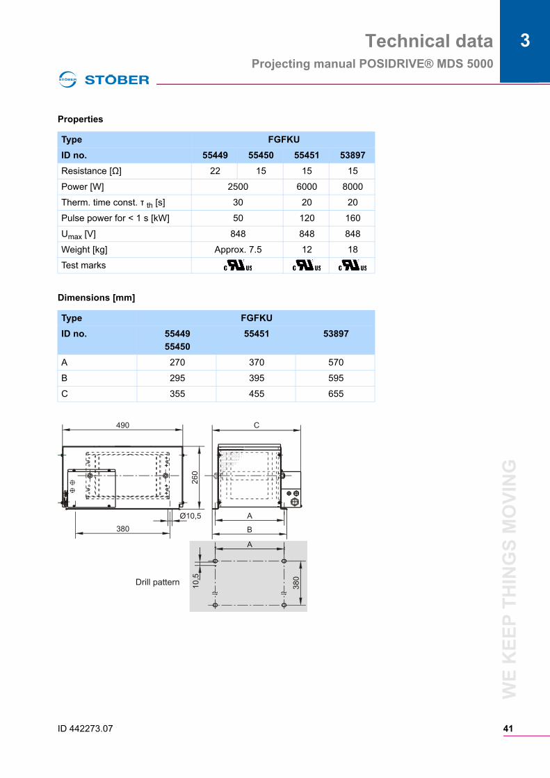
Properties
Dimensions [mm]
Type FGFKU
ID no. 55449 55450 55451 53897
Resistance [Ω] 22 15 15 15
Power [W] 2500 6000 8000
Therm. time const. τ th [s] 30 20 20
Pulse power for < 1 s [kW] 50 120 160
Umax [V] 848 848 848
Weight [kg] Approx. 7.5 12 18
Test marks
Type FGFKU
ID no. 55449
55450
55451 53897
A 270 370 570
B 295 395 595
C 355 455 655
490 C
A
B
Ø10,5
380
260
A
10,5
380Drill pattern
ID 442273.07 41
Technical data
42
Projecting manual POSIDRIVE® MDS 5000
3W
E K
EE
P T
HIN
GS
MO
VIN
G
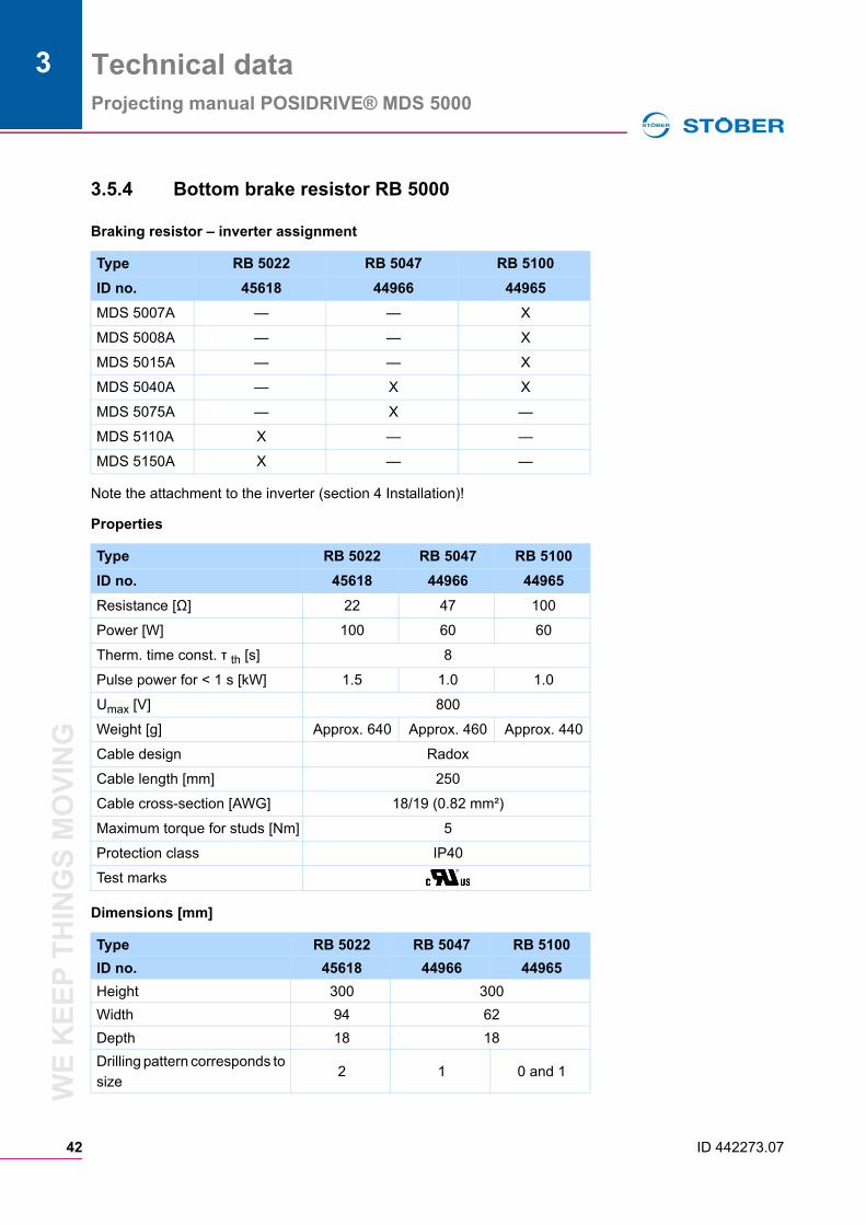
3.5.4 Bottom brake resistor RB 5000
Braking resistor – inverter assignment
Note the attachment to the inverter (section 4 Installation)!
Properties
Dimensions [mm]
Type RB 5022 RB 5047 RB 5100
ID no. 45618 44966 44965
MDS 5007A — — X
MDS 5008A — — X
MDS 5015A — — X
MDS 5040A — X X
MDS 5075A — X —
MDS 5110A X — —
MDS 5150A X — —
Type RB 5022 RB 5047 RB 5100
ID no. 45618 44966 44965
Resistance [Ω] 22 47 100
Power [W] 100 60 60
Therm. time const. τ th [s] 8
Pulse power for < 1 s [kW] 1.5 1.0 1.0
Umax [V] 800
Weight [g] Approx. 640 Approx. 460 Approx. 440
Cable design Radox
Cable length [mm] 250
Cable cross-section [AWG] 18/19 (0.82 mm²)
Maximum torque for studs [Nm] 5
Protection class IP40
Test marks
Type RB 5022 RB 5047 RB 5100
ID no. 45618 44966 44965
Height 300 300
Width 94 62
Depth 18 18
Drilling pattern corresponds to
size2 1 0 and 1
ID 442273.07

Technical dataProjecting manual POSIDRIVE® MDS 5000
WE
KE
EP
TH
ING
S M
OV
ING
3
3.6 Output derater
WARNING!
Risk of burns! Fire hazard! Material damage!
Chokes can heat up to over 100°C under permitted operating conditions.
Take protective measures against accidental and intentional contact with the choke.
Make sure that no flammable material is in the vicinity of the choke.
Do not install chokes under or near the inverter.
WARNING!
Fire hazard!
Using chokes outside of the nominal data (cable length, current, frequency, etc.) can cause the chokes to
overheat.
Always comply with the maximum nominal data when operating the chokes.
NOTICE
Danger of machine standstill!
The motor temperature sensor evaluation is malfunctioning due to cable capacities.
If you use cables which are longer than 50 m and the cables are not from STOBER, the cores for the motor
temperature sensor and the brake must be separate (maximum length: 100 m).
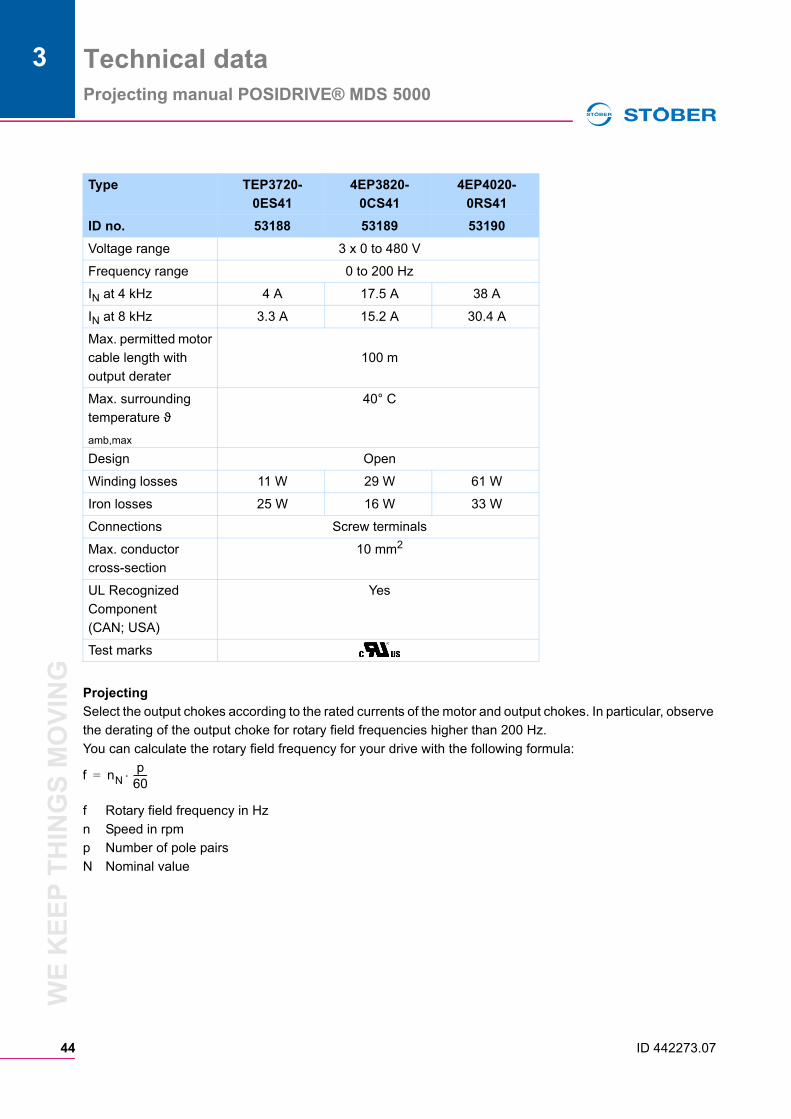
Information
The following technical data applies for a rotary field frequency of 200 Hz. For example, this rotary
field frequency is achieved with a motor with 4 pole pairs and a nominal speed of 3000 rpm.
Always observe the specified derating for higher rotary field frequencies.
Also observe the dependency of the cycle frequency.
ID 442273.07 43
Technical data
44
Projecting manual POSIDRIVE® MDS 5000
3W
E K
EE
P T
HIN
GS
MO
VIN
G
Projecting
Select the output chokes according to the rated currents of the motor and output chokes. In particular, observe
the derating of the output choke for rotary field frequencies higher than 200 Hz.
You can calculate the rotary field frequency for your drive with the following formula:
f Rotary field frequency in Hz
n Speed in rpm
p Number of pole pairs
N Nominal value
Type TEP3720-
0ES41
4EP3820-
0CS41
4EP4020-
0RS41
ID no. 53188 53189 53190
Voltage range 3 x 0 to 480 V
Frequency range 0 to 200 Hz
IN at 4 kHz 4 A 17.5 A 38 A
IN at 8 kHz 3.3 A 15.2 A 30.4 A
Max. permitted motor
cable length with
output derater
100 m
Max. surrounding
temperature ϑ
amb,max
40° C
Design Open
Winding losses 11 W 29 W 61 W
Iron losses 25 W 16 W 33 W
Connections Screw terminals
Max. conductor
cross-section
10 mm2
UL Recognized
Component (CAN; USA)
Yes
Test marks
f nNp
60------=
ID 442273.07
Technical dataProjecting manual POSIDRIVE® MDS 5000
WE
KE
EP
TH
ING
S M
OV
ING
3
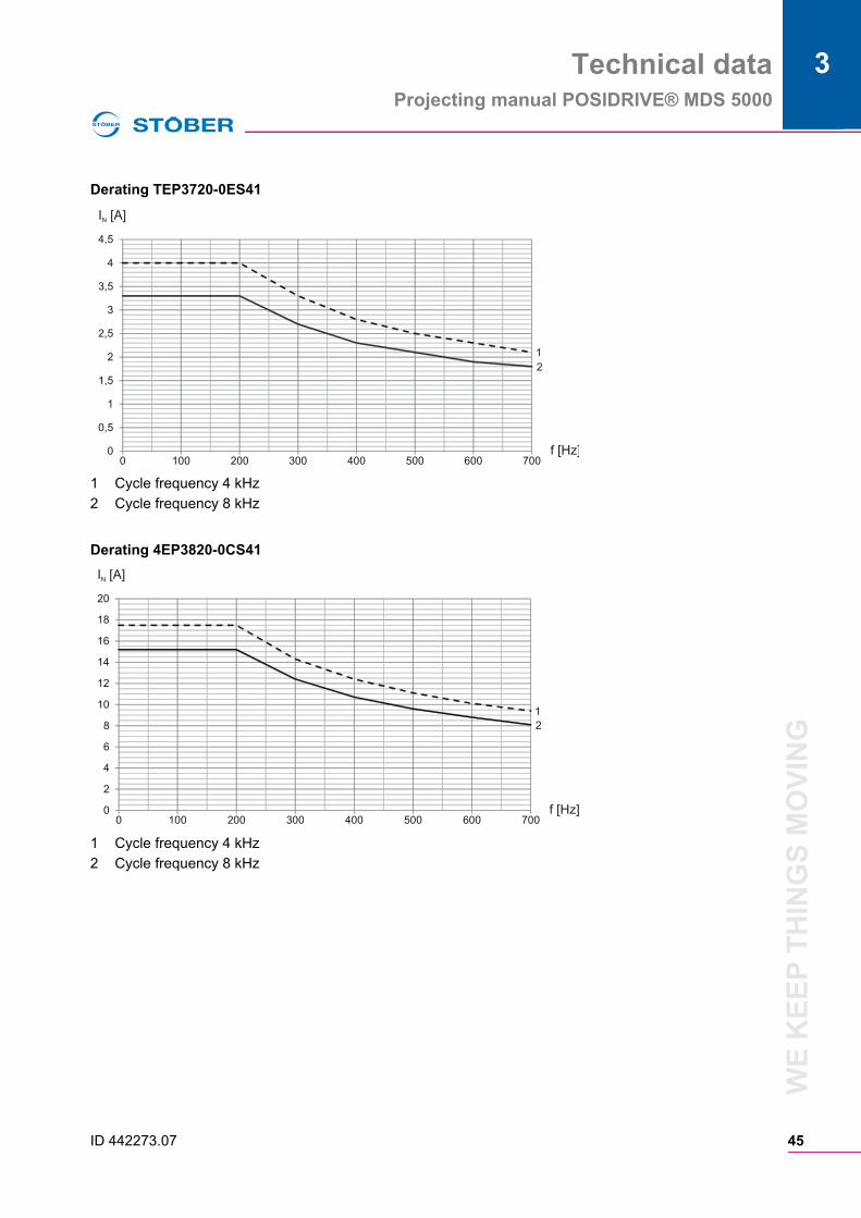
Derating TEP3720-0ES41
1 Cycle frequency 4 kHz
2 Cycle frequency 8 kHz
Derating 4EP3820-0CS41
1 Cycle frequency 4 kHz
2 Cycle frequency 8 kHz
0
0,5
1
1,5
2
2,5
3
3,5
4
4,5
0 100 200 300 400 500 600 700
12
IN [A]
f [Hz]
0
2
4
6
8
10
12
14
16
18
20
0 100 200 300 400 500 600 700
12
IN [A]
f [Hz]
ID 442273.07 45
Technical data
46
Projecting manual POSIDRIVE® MDS 5000
3W
E K
EE
P T
HIN
GS
MO
VIN
G
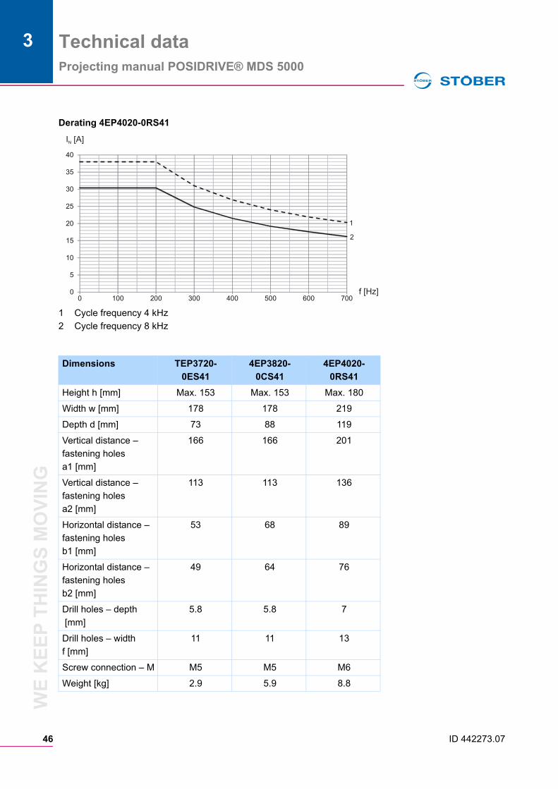
Derating 4EP4020-0RS41
1 Cycle frequency 4 kHz
2 Cycle frequency 8 kHz
Dimensions TEP3720-
0ES41
4EP3820-
0CS41
4EP4020-
0RS41
Height h [mm] Max. 153 Max. 153 Max. 180
Width w [mm] 178 178 219
Depth d [mm] 73 88 119
Vertical distance –
fastening holesa1 [mm]
166 166 201
Vertical distance –
fastening holesa2 [mm]
113 113 136
Horizontal distance –
fastening holesb1 [mm]
53 68 89
Horizontal distance –
fastening holesb2 [mm]
49 64 76
Drill holes – depth [mm]
5.8 5.8 7
Drill holes – width f [mm]
11 11 13
Screw connection – M M5 M5 M6
Weight [kg] 2.9 5.9 8.8
0
5
10
15
20
25
30
35
40
0 100 200 300 400 500 600 700
1
2
IN [A]
f [Hz]
ID 442273.07
Technical dataProjecting manual POSIDRIVE® MDS 5000
WE
KE
EP
TH
ING
S M
OV
ING
3
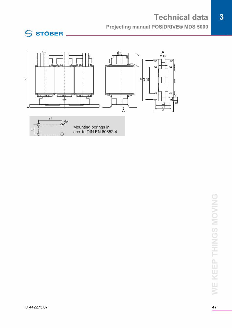
h a1wAb1b2
f
e
d
AM 1:2
a2
a1
b1
M
Mounting borings inacc. to DIN EN 60852-4
ID 442273.07 47
Installation
48
Projecting manual POSIDRIVE® MDS 5000
4W
E K
EE
P T
HIN
GS
MO
VIN
G
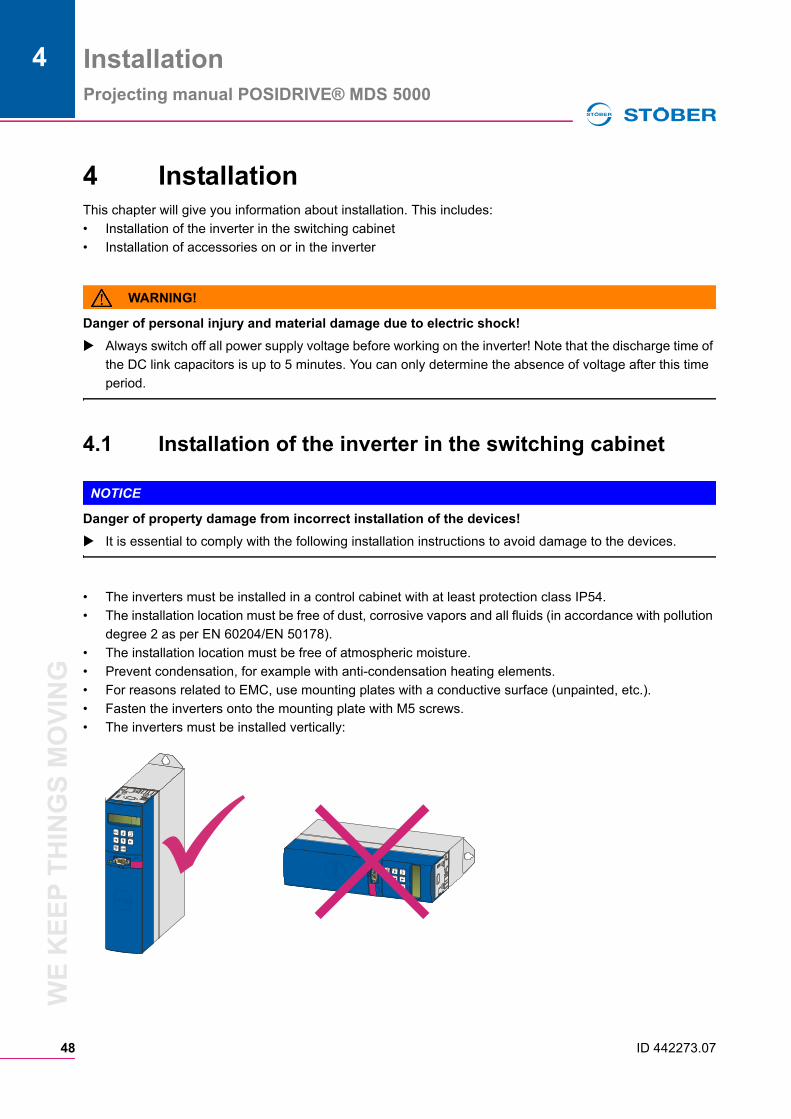
4 InstallationThis chapter will give you information about installation. This includes:
• Installation of the inverter in the switching cabinet
• Installation of accessories on or in the inverter
WARNING!
Danger of personal injury and material damage due to electric shock!
Always switch off all power supply voltage before working on the inverter! Note that the discharge time of
the DC link capacitors is up to 5 minutes. You can only determine the absence of voltage after this time
period.
4.1 Installation of the inverter in the switching cabinet
NOTICE
Danger of property damage from incorrect installation of the devices!
It is essential to comply with the following installation instructions to avoid damage to the devices.
• The inverters must be installed in a control cabinet with at least protection class IP54.
• The installation location must be free of dust, corrosive vapors and all fluids (in accordance with pollution
degree 2 as per EN 60204/EN 50178).
• The installation location must be free of atmospheric moisture.
• Prevent condensation, for example with anti-condensation heating elements.
• For reasons related to EMC, use mounting plates with a conductive surface (unpainted, etc.).
• Fasten the inverters onto the mounting plate with M5 screws.
• The inverters must be installed vertically:
ID 442273.07
InstallationProjecting manual POSIDRIVE® MDS 5000
WE
KE
EP
TH
ING
S M
OV
ING
4
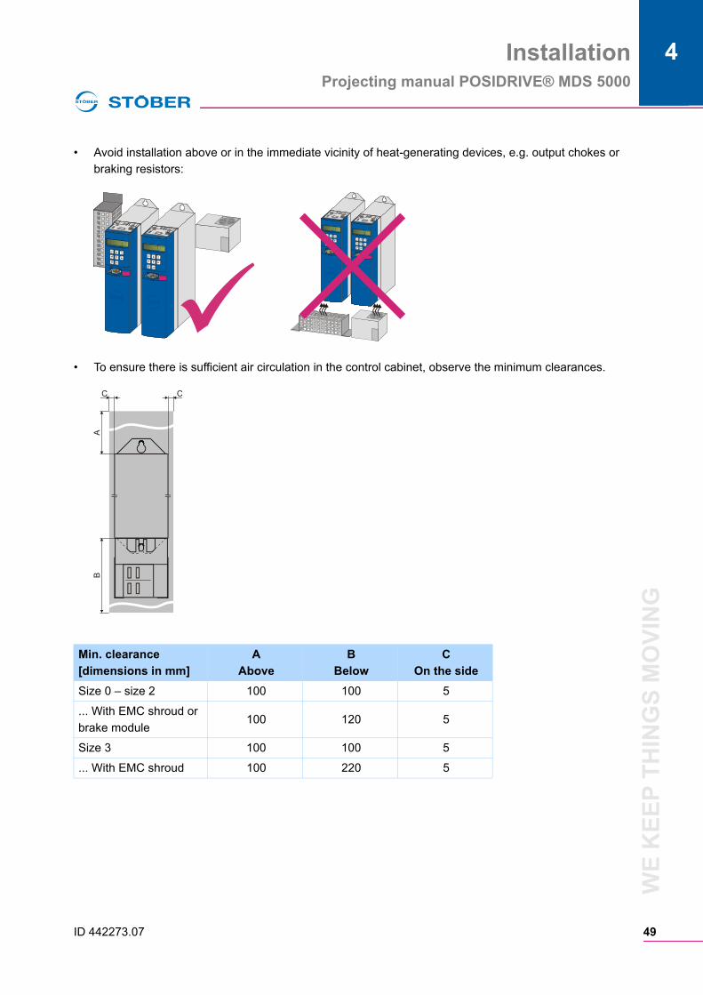
• Avoid installation above or in the immediate vicinity of heat-generating devices, e.g. output chokes or
braking resistors:
• To ensure there is sufficient air circulation in the control cabinet, observe the minimum clearances.
Min. clearance[dimensions in mm]
A
Above
B
Below
C
On the side
Size 0 – size 2 100 100 5
... With EMC shroud or
brake module100 120 5
Size 3 100 100 5
... With EMC shroud 100 220 5
AB
CC
ID 442273.07 49
Installation
50
Projecting manual POSIDRIVE® MDS 5000
4W
E K
EE
P T
HIN
GS
MO
VIN
G
4.2 Accessories
4.2.1 Installation of bottom brake resistor
WARNING!
Danger of personal injury and material damage due to electric shock!
Always switch off all power supply voltage before working on the inverter! Note that the discharge time of
the DC link capacitors is up to 5 minutes. You can only determine the absence of voltage after this time
period.
Requirements:
• You have tapped holes for threaded bolts on the mounting plate in the control cabinet at the installation
location, taking into consideration the different device dimensions. The threaded bolts are included with
the submounting braking resistor.
You need:
• The threaded bolts included with the submounting brake resistor.
• The screws and washers included with the submounting brake resistor.
• A PH2 Phillips screwdriver.
• An 8 mm hexagonal socket wrench.
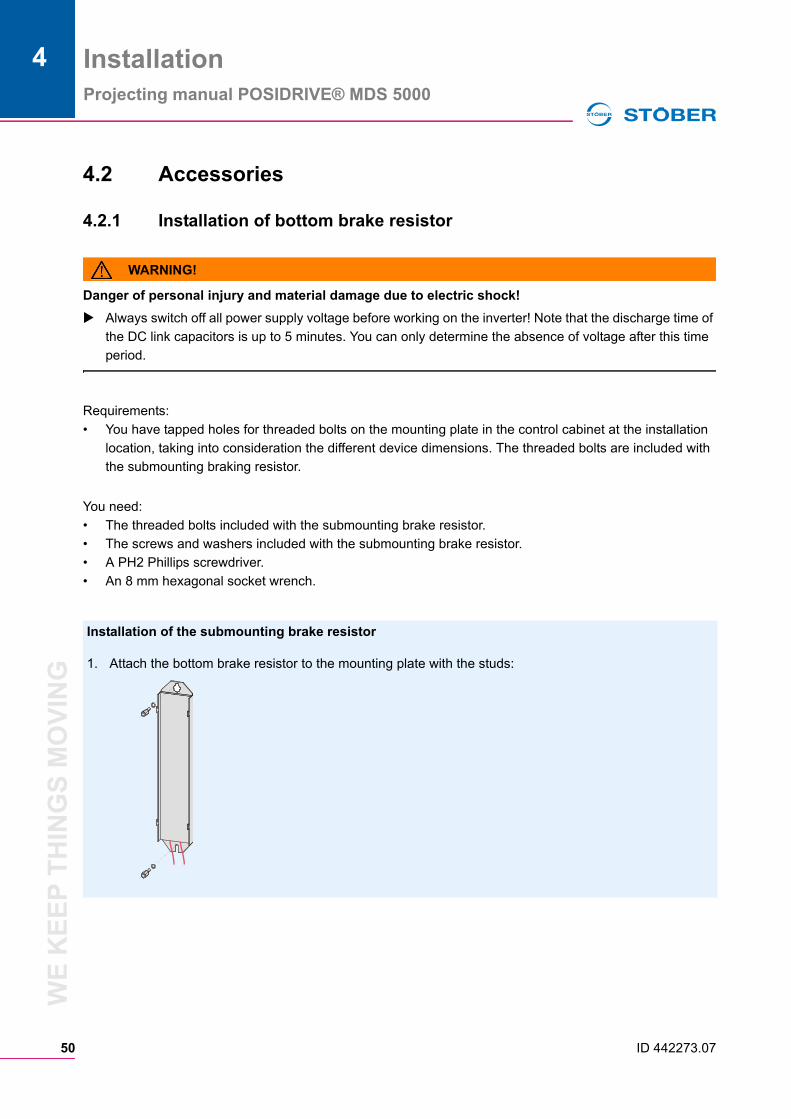
Installation of the submounting brake resistor
1. Attach the bottom brake resistor to the mounting plate with the studs:
ID 442273.07
InstallationProjecting manual POSIDRIVE® MDS 5000
WE
KE
EP
TH
ING
S M
OV
ING
4
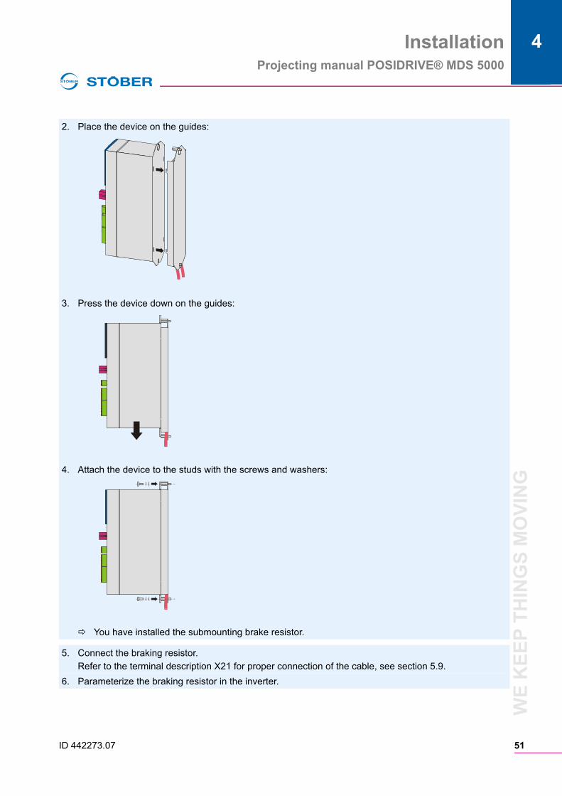
2. Place the device on the guides:
3. Press the device down on the guides:
4. Attach the device to the studs with the screws and washers:
You have installed the submounting brake resistor.
5. Connect the braking resistor.
Refer to the terminal description X21 for proper connection of the cable, see section 5.9.
6. Parameterize the braking resistor in the inverter.
ID 442273.07 51
Installation
52
Projecting manual POSIDRIVE® MDS 5000
4W
E K
EE
P T
HIN
GS
MO
VIN
G
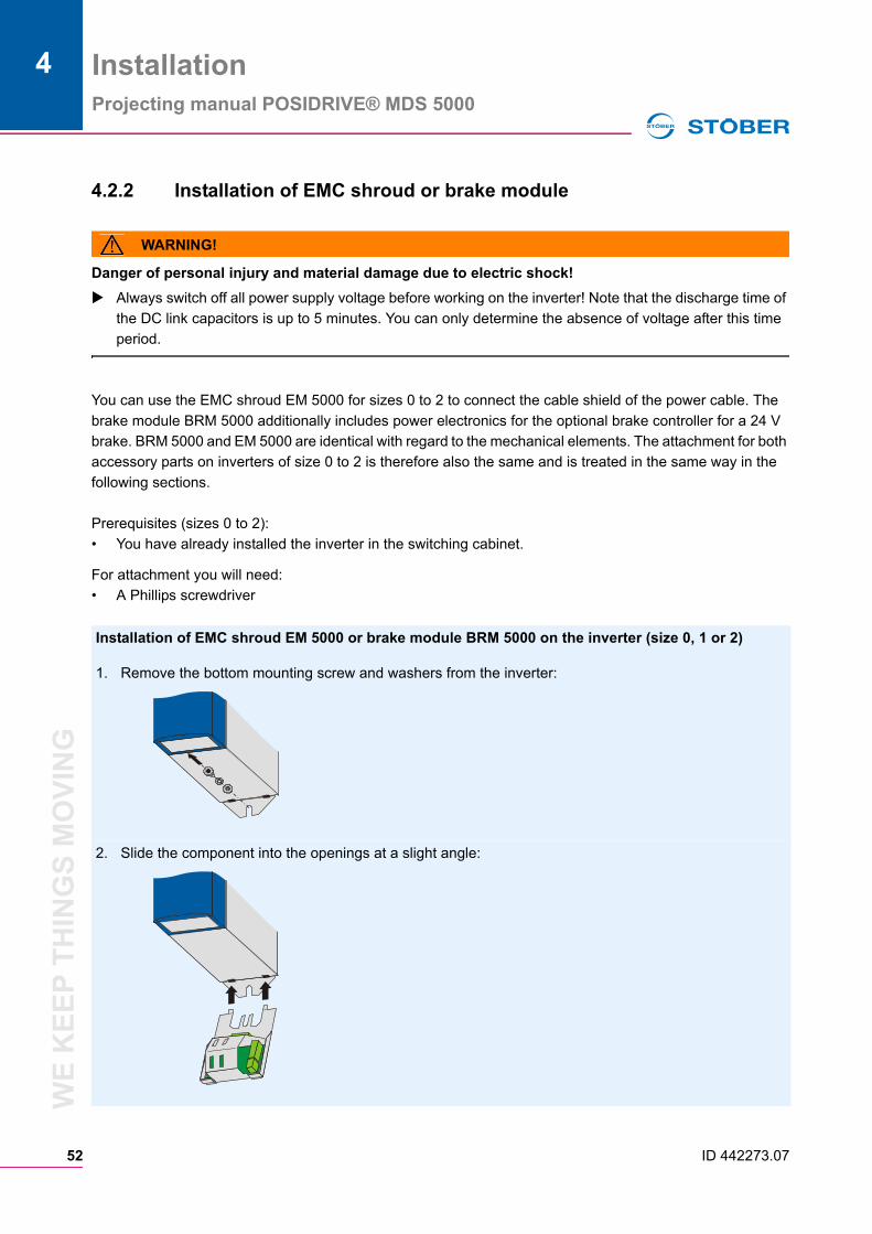
4.2.2 Installation of EMC shroud or brake module
WARNING!
Danger of personal injury and material damage due to electric shock!
Always switch off all power supply voltage before working on the inverter! Note that the discharge time of
the DC link capacitors is up to 5 minutes. You can only determine the absence of voltage after this time
period.
You can use the EMC shroud EM 5000 for sizes 0 to 2 to connect the cable shield of the power cable. The
brake module BRM 5000 additionally includes power electronics for the optional brake controller for a 24 V
brake. BRM 5000 and EM 5000 are identical with regard to the mechanical elements. The attachment for both
accessory parts on inverters of size 0 to 2 is therefore also the same and is treated in the same way in the
following sections.
Prerequisites (sizes 0 to 2):
• You have already installed the inverter in the switching cabinet.
For attachment you will need:
• A Phillips screwdriver
Installation of EMC shroud EM 5000 or brake module BRM 5000 on the inverter (size 0, 1 or 2)
1. Remove the bottom mounting screw and washers from the inverter:
2. Slide the component into the openings at a slight angle:
ID 442273.07
InstallationProjecting manual POSIDRIVE® MDS 5000
WE
KE
EP
TH
ING
S M
OV
ING
4
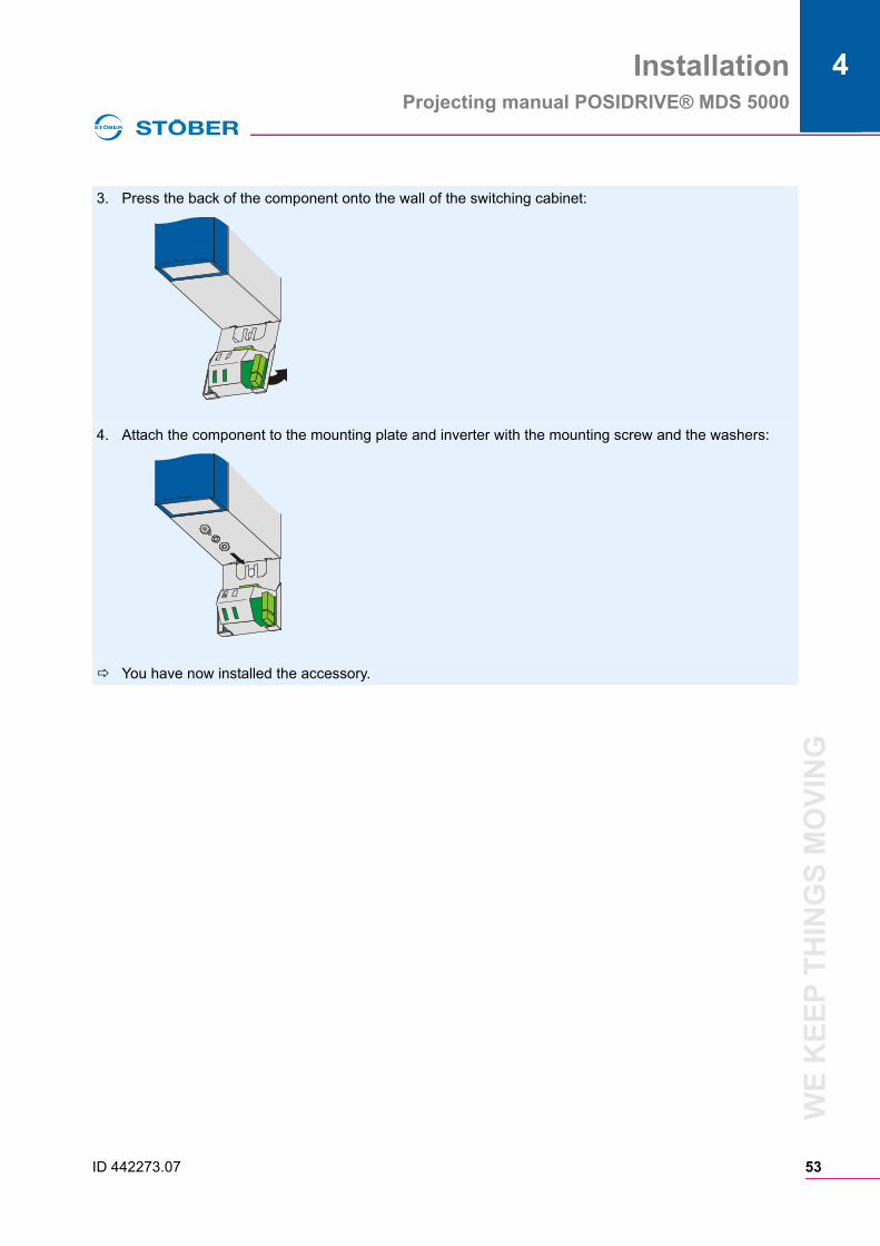
3. Press the back of the component onto the wall of the switching cabinet:
4. Attach the component to the mounting plate and inverter with the mounting screw and the washers:
You have now installed the accessory.
ID 442273.07 53
Installation
54
Projecting manual POSIDRIVE® MDS 5000
4W
E K
EE
P T
HIN
GS
MO
VIN
G
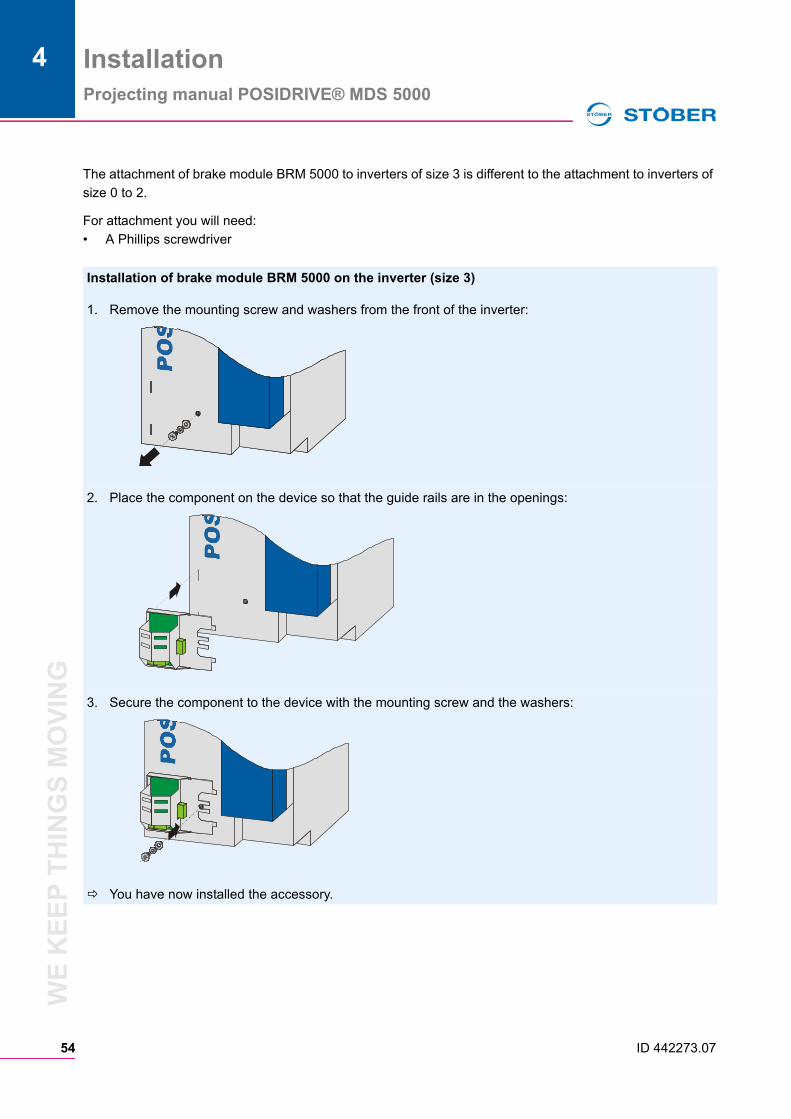
The attachment of brake module BRM 5000 to inverters of size 3 is different to the attachment to inverters of
size 0 to 2.
For attachment you will need:
• A Phillips screwdriver
Installation of brake module BRM 5000 on the inverter (size 3)
1. Remove the mounting screw and washers from the front of the inverter:
2. Place the component on the device so that the guide rails are in the openings:
3. Secure the component to the device with the mounting screw and the washers:
You have now installed the accessory.
ID 442273.07

InstallationProjecting manual POSIDRIVE® MDS 5000
WE
KE
EP
TH
ING
S M
OV
ING
4
For size 3, the larger EMC shroud EM6A3 for the shield connection of the motor line is available, see section
7 Accessories.
For attachment you will need:
• A Phillips screwdriver
• The two enclosed screws and washers (combination screws with toothed lock washer, M4x8)
4.2.3 Installation of the terminal accessories
WARNING!
Danger of personal injury and material damage due to electric shock!
Always switch off all power supply voltage before working on the inverter! Note that the discharge time of
the DC link capacitors is up to 5 minutes. You can only determine the absence of voltage after this time
period.
CAUTION!
Danger of property damage due to electrostatic discharge, among others!
Provide suitable protective measures while handling open PCBs (e.g., ESD clothing, environment free of
dirt and grease).
Do not touch the contact surfaces.
You will need one of the following accessory parts before you can connect binary and analog signals to the
inverter. Installation is the same for all four accessory parts:
• SEA 5001, ID no. 49576
• REA 5001, ID no. 49854
• XEA 5001, ID no. 49015
You will need:
• A Phillips screwdriver
• The screws which are pre-mounted on the accessory.
Attaching the EMC shroud EM6A3 to an inverter (size 3)
1. Fasten the part onto the bottom of the inverter with the enclosed fastening screws in the tapped holes
provided for that purpose (maximum tightening torque: 2.4 Nm).
ID 442273.07 55
Installation
56
Projecting manual POSIDRIVE® MDS 5000
4W
E K
EE
P T
HIN
GS
MO
VIN
G
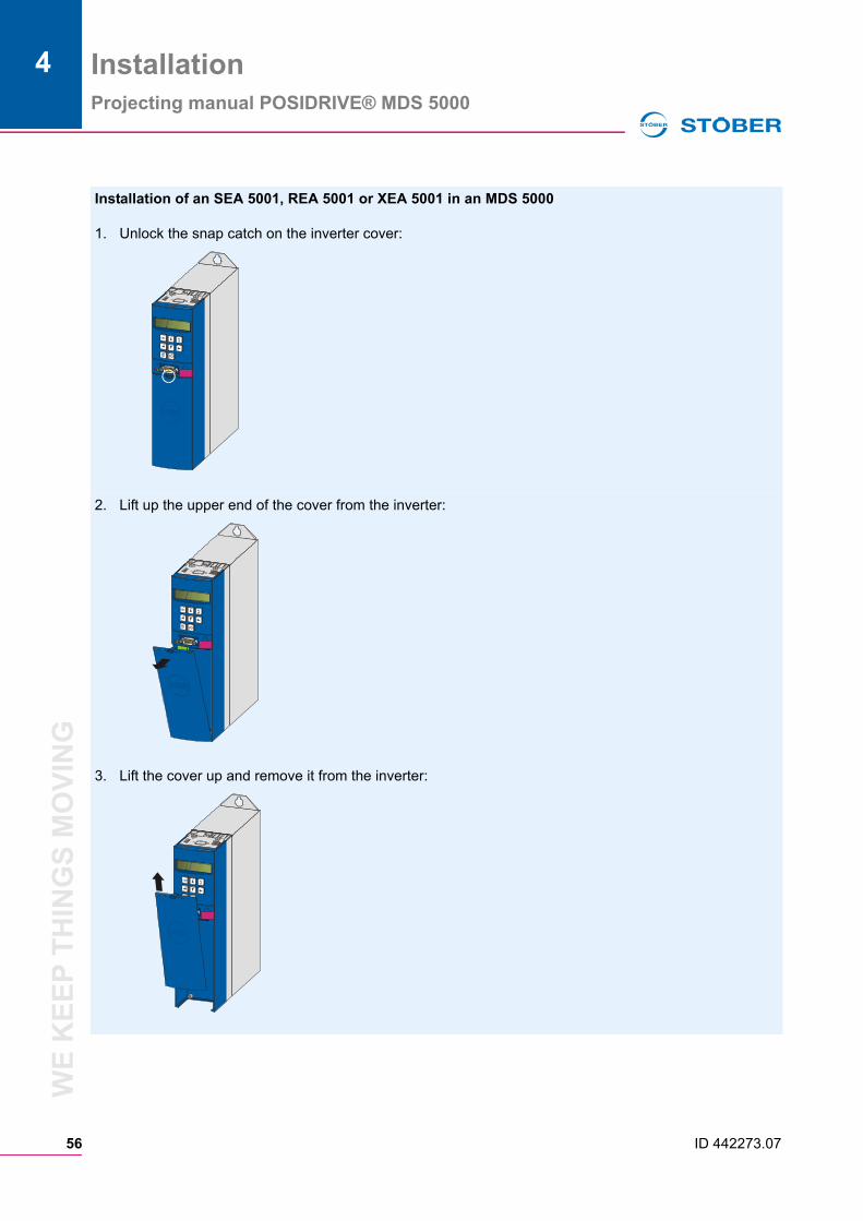
Installation of an SEA 5001, REA 5001 or XEA 5001 in an MDS 5000
1. Unlock the snap catch on the inverter cover:
2. Lift up the upper end of the cover from the inverter:
3. Lift the cover up and remove it from the inverter:
ID 442273.07
InstallationProjecting manual POSIDRIVE® MDS 5000
WE
KE
EP
TH
ING
S M
OV
ING
4
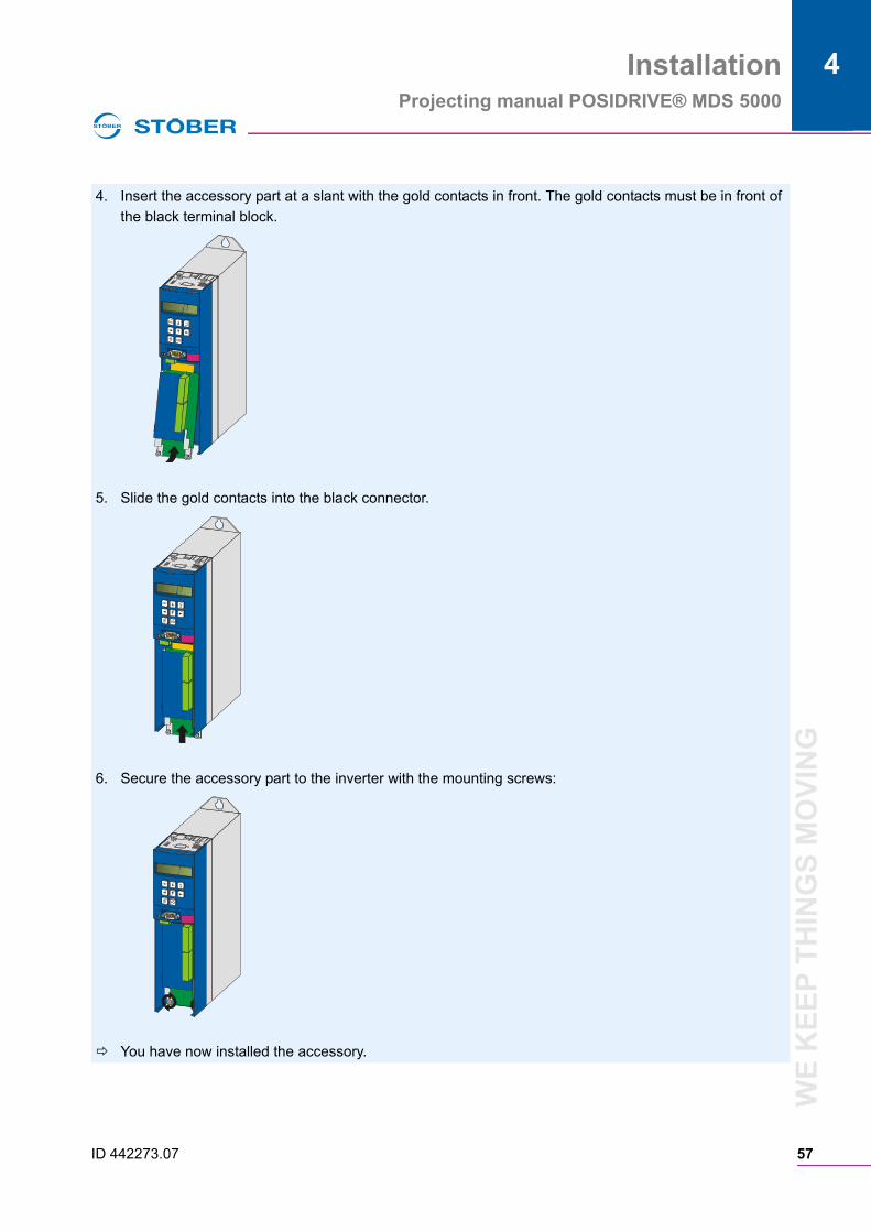
4. Insert the accessory part at a slant with the gold contacts in front. The gold contacts must be in front of
the black terminal block.
5. Slide the gold contacts into the black connector.
6. Secure the accessory part to the inverter with the mounting screws:
You have now installed the accessory.
ID 442273.07 57
Installation
58
Projecting manual POSIDRIVE® MDS 5000
4W
E K
EE
P T
HIN
GS
MO
VIN
G
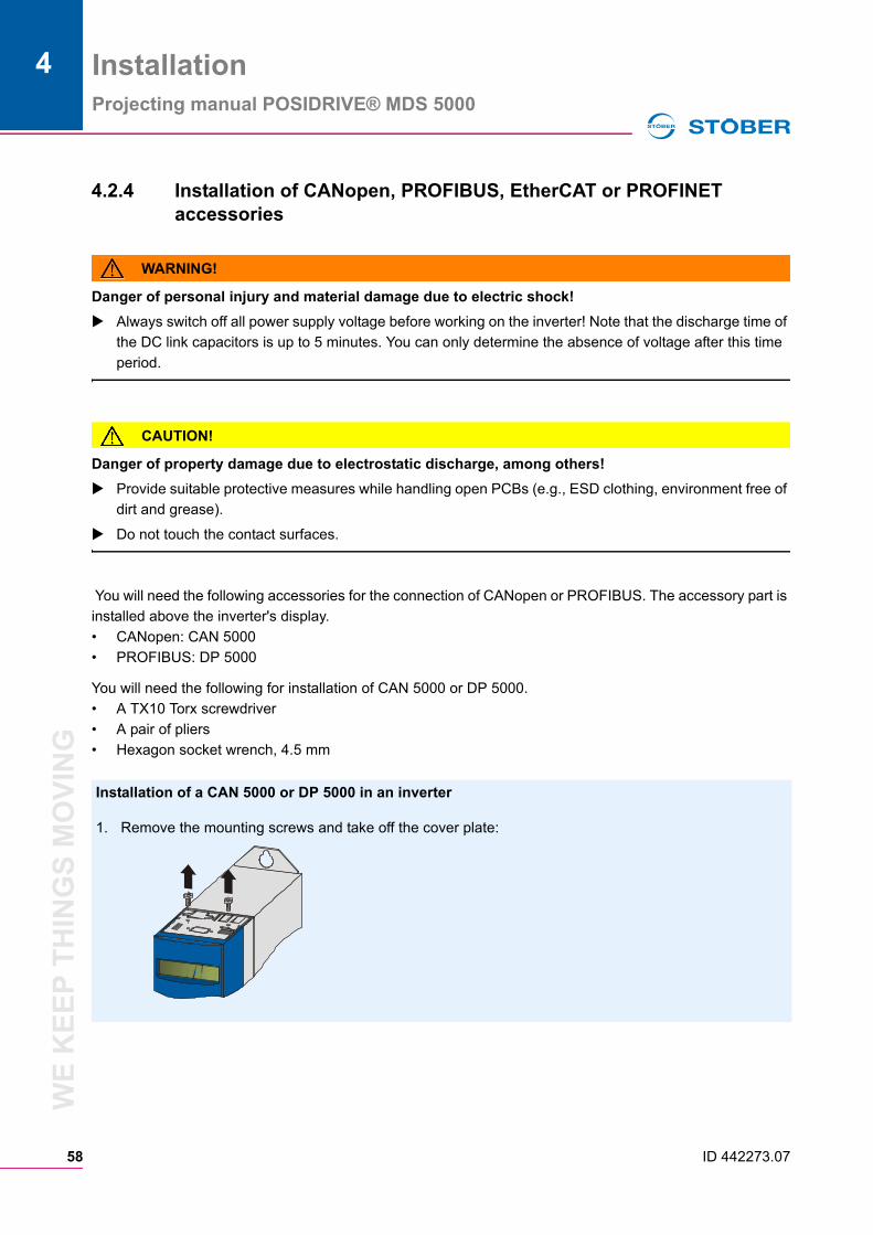
4.2.4 Installation of CANopen, PROFIBUS, EtherCAT or PROFINET accessories
WARNING!
Danger of personal injury and material damage due to electric shock!
Always switch off all power supply voltage before working on the inverter! Note that the discharge time of
the DC link capacitors is up to 5 minutes. You can only determine the absence of voltage after this time
period.
CAUTION!
Danger of property damage due to electrostatic discharge, among others!
Provide suitable protective measures while handling open PCBs (e.g., ESD clothing, environment free of
dirt and grease).
Do not touch the contact surfaces.
You will need the following accessories for the connection of CANopen or PROFIBUS. The accessory part is
installed above the inverter's display.
• CANopen: CAN 5000
• PROFIBUS: DP 5000
You will need the following for installation of CAN 5000 or DP 5000.
• A TX10 Torx screwdriver
• A pair of pliers
• Hexagon socket wrench, 4.5 mm
Installation of a CAN 5000 or DP 5000 in an inverter
1. Remove the mounting screws and take off the cover plate:
ID 442273.07
InstallationProjecting manual POSIDRIVE® MDS 5000
WE
KE
EP
TH
ING
S M
OV
ING
4
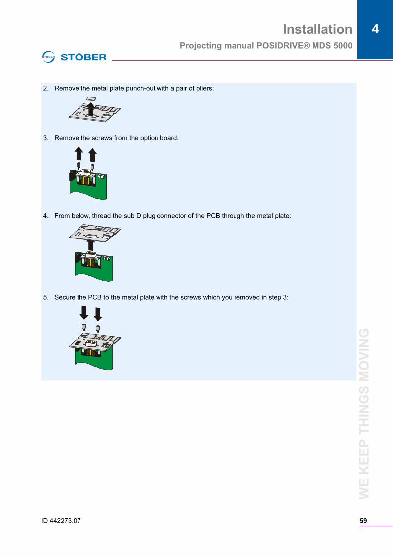
2. Remove the metal plate punch-out with a pair of pliers:
3. Remove the screws from the option board:
4. From below, thread the sub D plug connector of the PCB through the metal plate:
5. Secure the PCB to the metal plate with the screws which you removed in step 3:
ID 442273.07 59
Installation
60
Projecting manual POSIDRIVE® MDS 5000
4W
E K
EE
P T
HIN
GS
MO
VIN
G
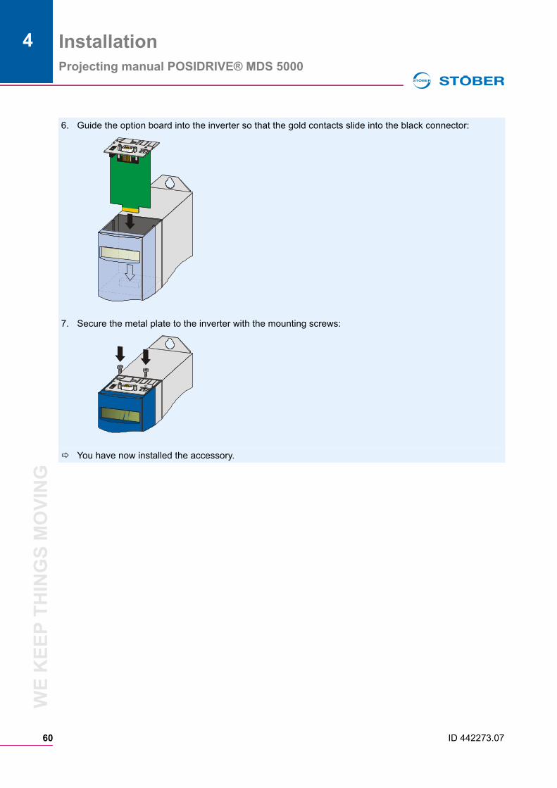
6. Guide the option board into the inverter so that the gold contacts slide into the black connector:
7. Secure the metal plate to the inverter with the mounting screws:
You have now installed the accessory.
ID 442273.07

InstallationProjecting manual POSIDRIVE® MDS 5000
WE
KE
EP
TH
ING
S M
OV
ING
4
You will need the following accessories for the connection of EtherCAT or PROFINET. The accessory part is
installed above the inverter's display.
• EtherCAT: ECS 5000
• PROFINET: PN 5000
You will require the following for installation:
• A TX10 Torx screwdriver
• A Phillips screwdriver
• the following cover plate, which is included in the accessories, is required for installing the ECS 5000:
• the following cover plate, which is included in the accessories, is required for installing the PN 5000:
• The screw with locking disk which is included with the ECS 5000 accessories.
Run BF
Installation of an ECS 5000 or PN 5000 in an inverter
1. Remove the mounting screws and take off the cover plate:
ID 442273.07 61
Installation
62
Projecting manual POSIDRIVE® MDS 5000
4W
E K
EE
P T
HIN
GS
MO
VIN
G
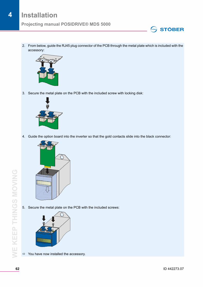
2. From below, guide the RJ45 plug connector of the PCB through the metal plate which is included with the accessory:
3. Secure the metal plate on the PCB with the included screw with locking disk:
4. Guide the option board into the inverter so that the gold contacts slide into the black connector:
5. Secure the metal plate on the PCB with the included screws:
You have now installed the accessory.
ID 442273.07
ConnectionProjecting manual POSIDRIVE® MDS 5000
WE
KE
EP
TH
ING
S M
OV
ING
5
5 Connection
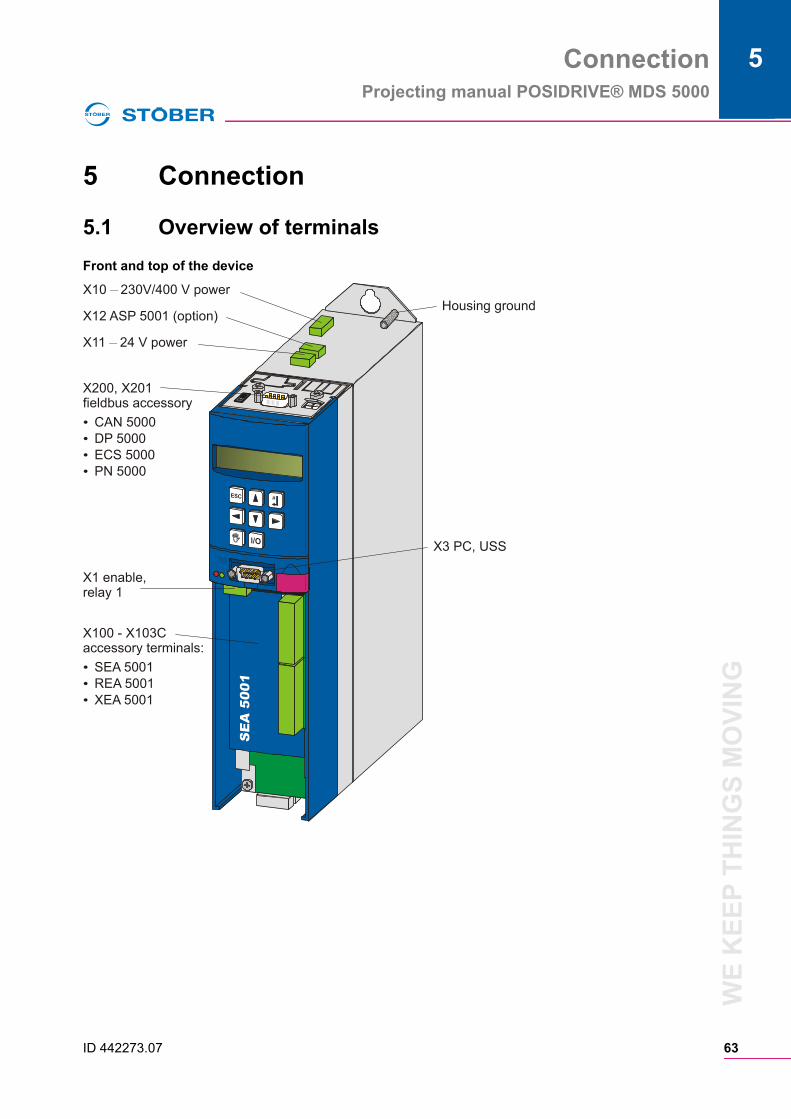
5.1 Overview of terminals
Front and top of the device
X10 230V/400 V power–
X12 ASP 5001 (option)
X11 24 V power–
X200, X201fieldbus accessory
•••
CAN 5000 DP 5000 ECS 5000
• PN 5000
••
SEA 5001 REA 5001
• XEA 5001
X1 enable,relay 1
X100 - X103Caccessory terminals:
X3 PC, USS
Housing ground
ID 442273.07 63
Connection
64
Projecting manual POSIDRIVE® MDS 5000
5W
E K
EE
P T
HIN
GS
MO
VIN
G
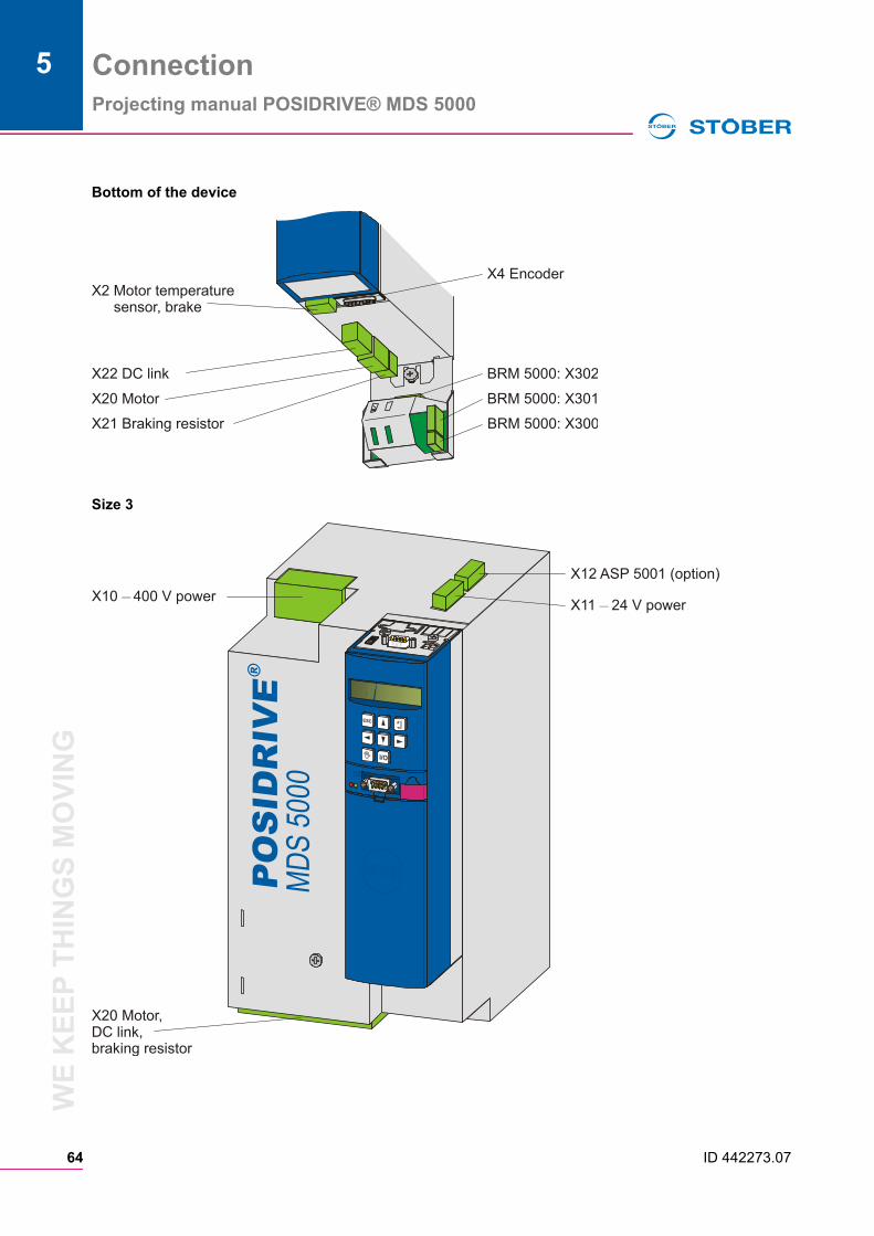
Bottom of the device
Size 3
X2 Motor temperature sensor, brake
X22 DC link BRM 5000: X302
X4 Encoder
X20 Motor BRM 5000: X301
X21 Braking resistor BRM 5000: X300
X10 400 V power–
X12 ASP 5001 (option)
X11 24 V power–
X20 Motor,DC link,braking resistor
ID 442273.07
ConnectionProjecting manual POSIDRIVE® MDS 5000
WE
KE
EP
TH
ING
S M
OV
ING
5
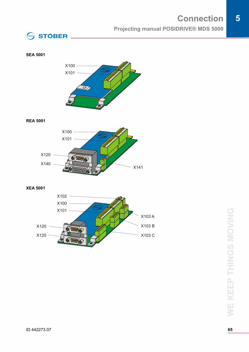
SEA 5001
REA 5001
XEA 5001
X101
X100
X141
X120
X140
X101
X100
X103 B
X103 C
X103 A
X101
X100
X120
X120
X102
ID 442273.07 65

Connection
66
Projecting manual POSIDRIVE® MDS 5000
5W
E K
EE
P T
HIN
GS
MO
VIN
G
5.2 EMC connection
• Install power line, motor cable and signal lines separately from each other (e.g., in separate cable ducts).
• Use only shielded cables for the motor cable. See also chapter 5.15 Cables.
• If the brake line is installed together with the motor cable, the brake line must be shielded separately.
• Apply the shield of the motor cable over a large surface and in the immediate vicinity of the inverter. For
this purpose, use the EMC shroud EM 5000 or the brake module BRM 5000 for the sizes 0 to 2 or the
EMC shroud EM6A3 for size 3.
• Shield the cable for the connection of a brake resistor if the cable is longer than 30 cm. In this case apply
the shield over a large surface in the immediate vicinity of the inverter.
• Always place the canopy with considerable spacing around the terminal box in the case of motors with
terminal boxes. You should use EMC cable connections.
• Connect the shield of the control lines on one side to the reference ground of the source (e.g., the PLC or
CNC).
Information
This chapter contains general information on EMC-suitable installation. These are only
recommendations. Depending on the application, the ambient conditions and the legal
requirements, measures in addition to this recommendations may be required.
ID 442273.07
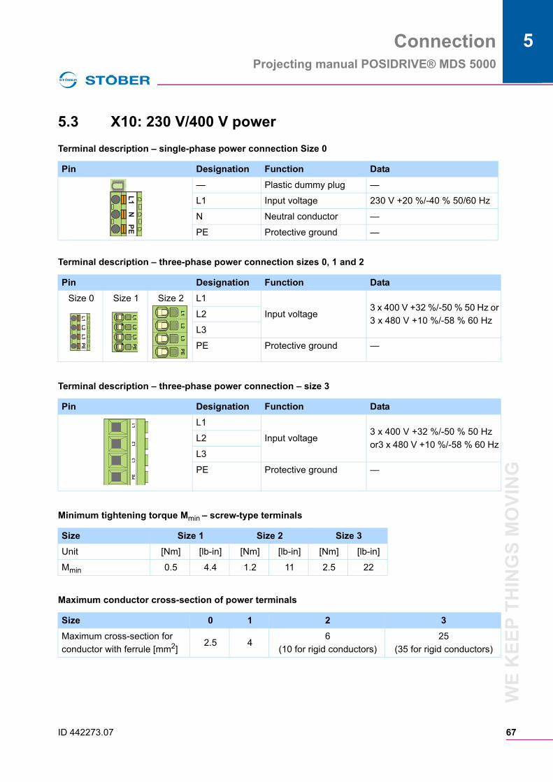
ConnectionProjecting manual POSIDRIVE® MDS 5000
WE
KE
EP
TH
ING
S M
OV
ING
5
5.3 X10: 230 V/400 V power
Terminal description – single-phase power connection Size 0
Terminal description – three-phase power connection sizes 0, 1 and 2
Terminal description – three-phase power connection – size 3
Minimum tightening torque Mmin – screw-type terminals
Maximum conductor cross-section of power terminals
Pin Designation Function Data
— Plastic dummy plug —
L1 Input voltage 230 V +20 %/-40 % 50/60 Hz
N Neutral conductor —
PE Protective ground —
Pin Designation Function Data
Size 0 Size 1 Size 2 L1
Input voltage3 x 400 V +32 %/-50 % 50 Hz or
3 x 480 V +10 %/-58 % 60 HzL2
L3
PE Protective ground —
Pin Designation Function Data
L1
Input voltage3 x 400 V +32 %/-50 % 50 Hz
or3 x 480 V +10 %/-58 % 60 HzL2
L3
PE Protective ground —
Size Size 1 Size 2 Size 3
Unit [Nm] [lb-in] [Nm] [lb-in] [Nm] [lb-in]
Mmin 0.5 4.4 1.2 11 2.5 22
Size 0 1 2 3
Maximum cross-section for
conductor with ferrule [mm2]2.5 4
6
(10 for rigid conductors)
25
(35 for rigid conductors)
L1
NP
E
L1
L2
L3
PE
L1
L2
L3
PE
L1
L2
L3
PE
L1
L2
L3
PE
ID 442273.07 67
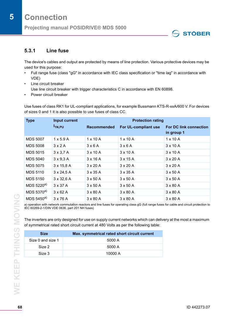
Connection
68
Projecting manual POSIDRIVE® MDS 5000
5W
E K
EE
P T
HIN
GS
MO
VIN
G
5.3.1 Line fuse
The device's cables and output are protected by means of line protection. Various protective devices may be
used for this purpose:
• Full range fuse (class "gG" in accordance with IEC class specification or "time lag" in accordance with
VDE)
• Line circuit breaker Use line circuit breaker with trigger characteristics C in accordance with EN 60898.
• Power circuit breaker
Use fuses of class RK1 for UL-compliant applications, for example Bussmann KTS-R-xxA/600 V. For devices
of sizes 0 and 1 it is also possible to use fuses of class CC.
The inverters are only designed for use on supply current networks which can delivery at the most a maximum
of symmetrical rated short circuit current at 480 Volts as per the following table:
Type Input current
I1N,PU
Protection rating
Recommended For UL-compliant use For DC link connection
in group 1
MDS 5007 1 x 5.9 A 1 x 10 A 1 x 10 A 1 x 10 A
MDS 5008 3 x 2 A 3 x 6 A 3 x 6 A 3 x 10 A
MDS 5015 3 x 3,7 A 3 x 10 A 3 x 10 A 3 x 10 A
MDS 5040 3 x 9,3 A 3 x 16 A 3 x 15 A 3 x 20 A
MDS 5075 3 x 15,8 A 3 x 20 A 3 x 20 A 3 x 20 A
MDS 5110 3 x 24,5 A 3 x 35 A 3 x 35 A 3 x 50 A
MDS 5150 3 x 32,6 A 3 x 50 A 3 x 50 A 3 x 50 A
MDS 5220a)
a) operation with network commutation reactors and line fuses for operating class gG (full range fuses for cable and circuit protection to IEC 60269-2-1/DIN VDE 0636, part 201 NH fuses)
3 x 37 A 3 x 50 A 3 x 50 A 3 x 80 A
MDS 5370a) 3 x 62 A 3 x 80 A 3 x 80 A 3 x 80 A
MDS 5450a) 3 x 76 A 3 x 80 A 3 x 80 A 3 x 80 A
Size Max. symmetrical rated short circuit current
Size 0 and size 1 5000 A
Size 2 5000 A
Size 3 10000 A
ID 442273.07

ConnectionProjecting manual POSIDRIVE® MDS 5000
WE
KE
EP
TH
ING
S M
OV
ING
5
5.3.2 Residual current safety device
STOBER devices can be protected with a Residual Current protective Devices (RCD) to detect residual
currents. Residual current protective devices prevent electrical accidents, especially ground fault through the
body. They are generally distinguished according to their triggering limit and suitability for detecting different
types of residual current.
Depending on the function, stray currents may occur when operating inverters. Stray currents are interpreted
as residual currents by residual current protective devices and may therefore lead to false triggering.
Depending on the relevant power supply connections, residual currents may occur with or without a DC
current component. Because of this, you should take into consideration both the height and also the shape of
the possible stray or residual current when selecting a suitable RCD.
DANGER!
Electric shock hazard!
The combination of single-phase inverters and residual current protective devices type A or AC can lead to
false triggering of the RCDs.
Stray currents with a DC current component may occur in 3-phase inverters.
Always protect single-phase inverters with residual current protective devices type B, sensitive to all
currents, or with type F, sensitive to mixed currents.
Always protect 3-phase inverters with residual current protective devices type B, sensitive to all currents.
False triggering – causes
Depending on stray capacitances and asymmetries, stray currents up to 40 mA may occur during operation.
Undesirable false triggering occurs
• ... when inverters to the supply voltage.This false triggering can be rectified by using short-time delayed (super-resistant), selective (delayed
switch-off) residual current protective devices or RCDs with increased trigger current (for example 300 or 500 mA).
• ... Due to higher frequency stray currents for long motor cables under normal operating conditions: This false triggering can be rectified for example using low-capacitance cables or output deraters.
• ... due to unbalances in the supply network. This false triggering can be rectified for example using an isolating transformer.
Information
Check whether the use of residual current protective devices with increased trigger current as well
as with short-time delayed or delayed switch-off trigger characteristics are permitted in your
application.
ID 442273.07 69
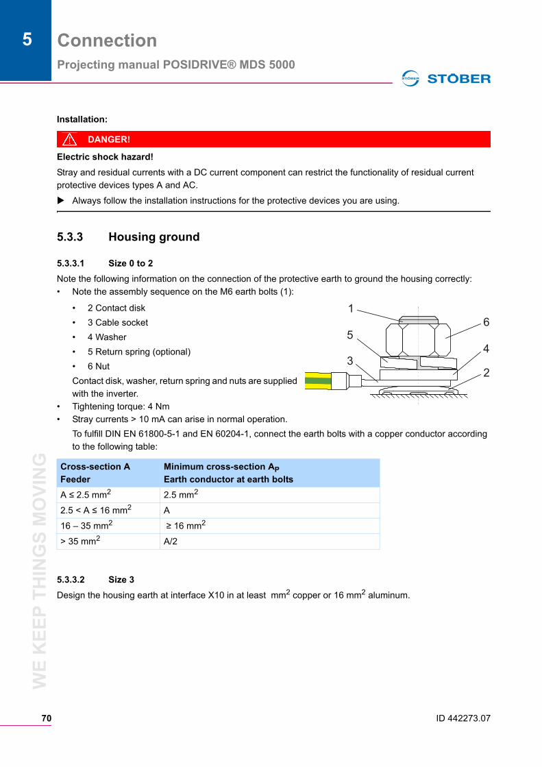
Connection
70
Projecting manual POSIDRIVE® MDS 5000
5W
E K
EE
P T
HIN
GS
MO
VIN
G
Installation:
DANGER!
Electric shock hazard!
Stray and residual currents with a DC current component can restrict the functionality of residual current
protective devices types A and AC.
Always follow the installation instructions for the protective devices you are using.
5.3.3 Housing ground
5.3.3.1 Size 0 to 2
Note the following information on the connection of the protective earth to ground the housing correctly:
• Note the assembly sequence on the M6 earth bolts (1):
• 2 Contact disk
• 3 Cable socket
• 4 Washer
• 5 Return spring (optional)
• 6 Nut
Contact disk, washer, return spring and nuts are supplied
with the inverter.
• Tightening torque: 4 Nm
• Stray currents > 10 mA can arise in normal operation.
To fulfill DIN EN 61800-5-1 and EN 60204-1, connect the earth bolts with a copper conductor according
to the following table:
5.3.3.2 Size 3
Design the housing earth at interface X10 in at least mm2 copper or 16 mm2 aluminum.
Cross-section A
Feeder
Minimum cross-section AP
Earth conductor at earth bolts
A ≤ 2.5 mm2 2.5 mm2
2.5 < A ≤ 16 mm2 A
16 – 35 mm2 ≥ 16 mm2
> 35 mm2 A/2
1
43
65
2
ID 442273.07
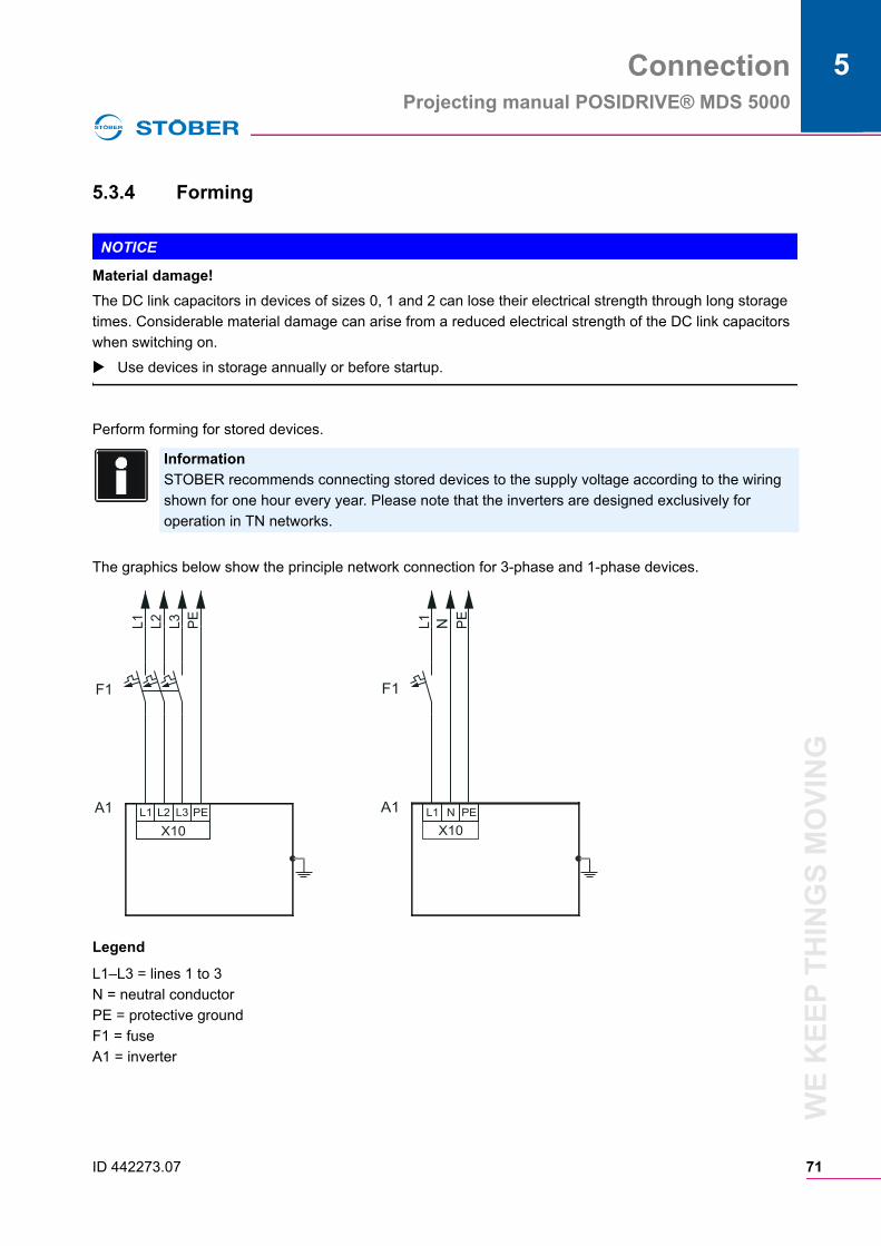
ConnectionProjecting manual POSIDRIVE® MDS 5000
WE
KE
EP
TH
ING
S M
OV
ING
5
5.3.4 Forming
NOTICE
Material damage!
The DC link capacitors in devices of sizes 0, 1 and 2 can lose their electrical strength through long storage
times. Considerable material damage can arise from a reduced electrical strength of the DC link capacitors
when switching on.
Use devices in storage annually or before startup.
Perform forming for stored devices.
The graphics below show the principle network connection for 3-phase and 1-phase devices.
Legend
L1–L3 = lines 1 to 3
N = neutral conductor
PE = protective ground
F1 = fuse
A1 = inverter
Information
STOBER recommends connecting stored devices to the supply voltage according to the wiring
shown for one hour every year. Please note that the inverters are designed exclusively for
operation in TN networks.
ID 442273.07 71
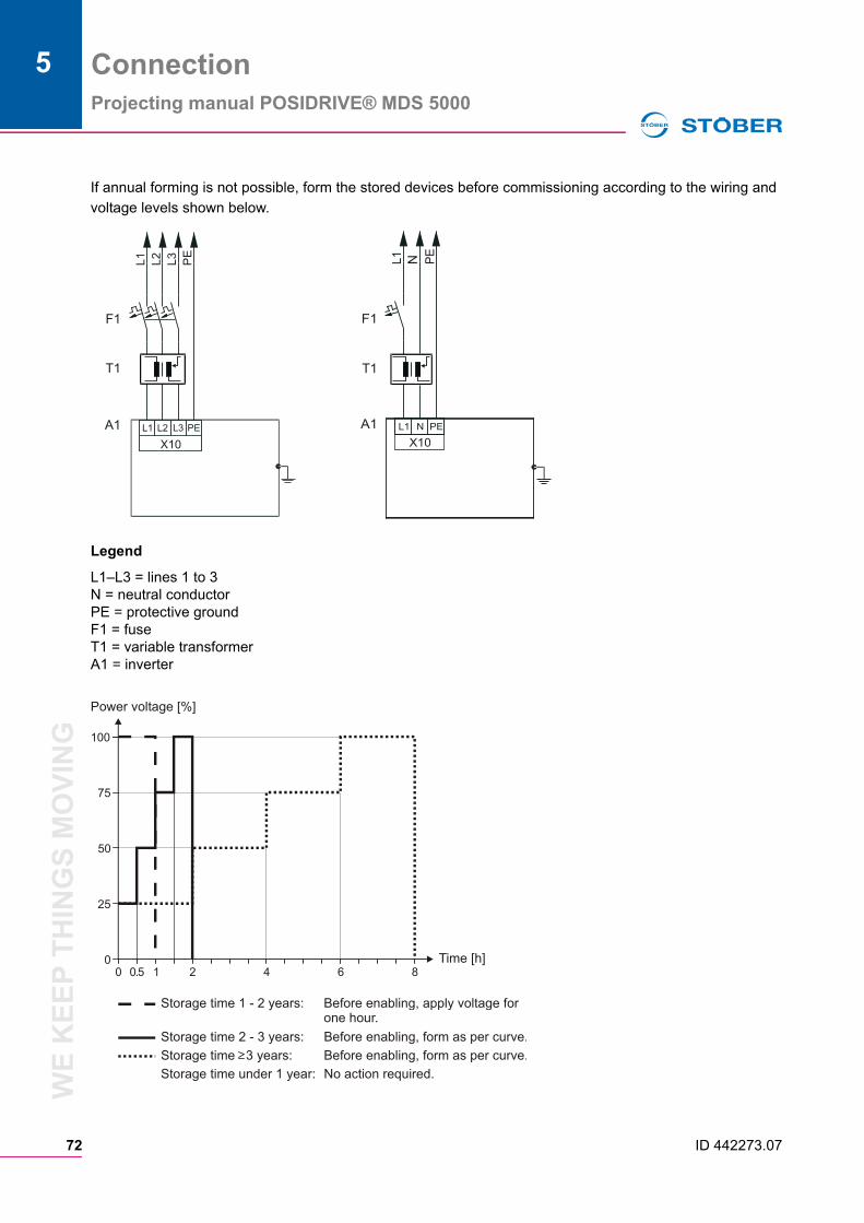
Connection
72
Projecting manual POSIDRIVE® MDS 5000
5W
E K
EE
P T
HIN
GS
MO
VIN
G
If annual forming is not possible, form the stored devices before commissioning according to the wiring and
voltage levels shown below.
Legend
L1–L3 = lines 1 to 3N = neutral conductorPE = protective groundF1 = fuseT1 = variable transformerA1 = inverter
X10
L1
L2
F1
L3
PE
L1 L2 L3 PEA1
X10
L1
F1
PE
L1 N PEA1
N
T1 T1
10.500
25
50
75
100
2 4 6 8Time [h]
Power voltage [%]
Storage time 1 - 2 years: Before enabling, apply voltage forone hour.
Storage time 2 - 3 years: Before enabling, form as per curve.
Storage time 3 years: Before enabling, form as per curve.
Storage time under 1 year: No action required.
ID 442273.07
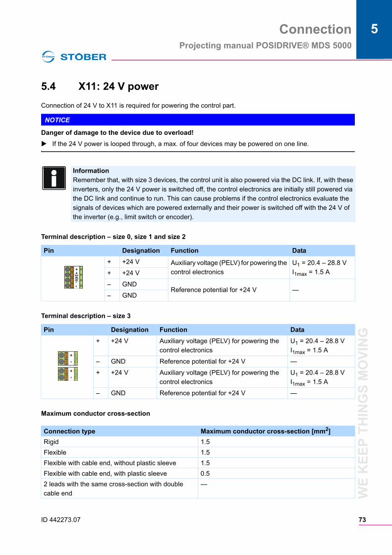
ConnectionProjecting manual POSIDRIVE® MDS 5000
WE
KE
EP
TH
ING
S M
OV
ING
5
5.4 X11: 24 V power
Connection of 24 V to X11 is required for powering the control part.
NOTICE
Danger of damage to the device due to overload!
If the 24 V power is looped through, a max. of four devices may be powered on one line.
Terminal description – size 0, size 1 and size 2
Terminal description – size 3
Information
Remember that, with size 3 devices, the control unit is also powered via the DC link. If, with these
inverters, only the 24 V power is switched off, the control electronics are initially still powered via
the DC link and continue to run. This can cause problems if the control electronics evaluate the
signals of devices which are powered externally and their power is switched off with the 24 V of
the inverter (e.g., limit switch or encoder).
Pin Designation Function Data
+ +24 V Auxiliary voltage (PELV) for powering the
control electronics
U1 = 20.4 – 28.8 V I1max = 1.5 A+ +24 V
– GNDReference potential for +24 V —
– GND
Pin Designation Function Data
+ +24 V Auxiliary voltage (PELV) for powering the
control electronics
U1 = 20.4 – 28.8 V I1max = 1.5 A
– GND Reference potential for +24 V —
+ +24 V Auxiliary voltage (PELV) for powering the
control electronics
U1 = 20.4 – 28.8 V I1max = 1.5 A
– GND Reference potential for +24 V —
Maximum conductor cross-section
Connection type Maximum conductor cross-section [mm2]
Rigid 1.5
Flexible 1.5
Flexible with cable end, without plastic sleeve 1.5
Flexible with cable end, with plastic sleeve 0.5
2 leads with the same cross-section with double
cable end
—
++
+
ID 442273.07 73
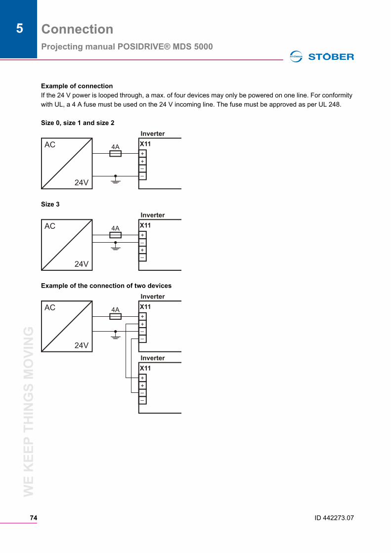
Connection
74
Projecting manual POSIDRIVE® MDS 5000
5W
E K
EE
P T
HIN
GS
MO
VIN
G
Example of connection
If the 24 V power is looped through, a max. of four devices may only be powered on one line. For conformity
with UL, a 4 A fuse must be used on the 24 V incoming line. The fuse must be approved as per UL 248.
Size 0, size 1 and size 2
Size 3
Example of the connection of two devices
4A+
_+
_
X11
Inverter
AC
24V
4A+_
+_
X11
Inverter
AC
24V
4A+
+
_
_
+
+
_
_
X11
X11
Inverter
Inverter
AC
24V
ID 442273.07
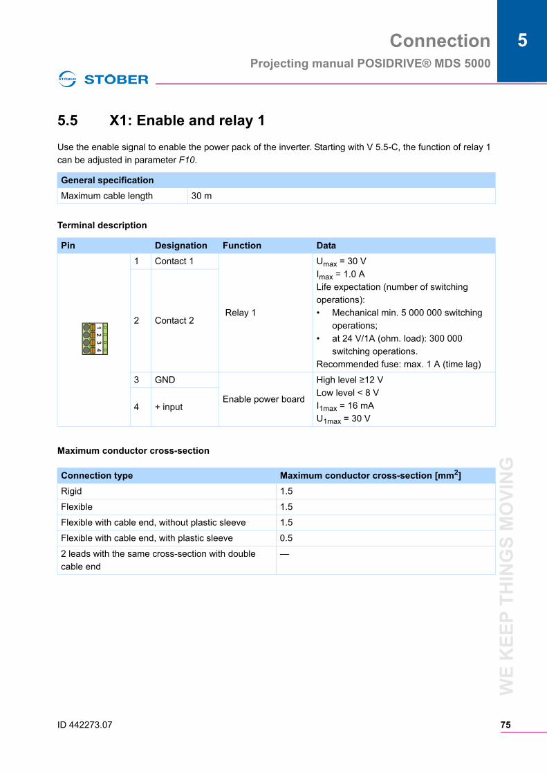
ConnectionProjecting manual POSIDRIVE® MDS 5000
WE
KE
EP
TH
ING
S M
OV
ING
5
5.5 X1: Enable and relay 1
Use the enable signal to enable the power pack of the inverter. Starting with V 5.5-C, the function of relay 1
can be adjusted in parameter F10.
Terminal description
General specification
Maximum cable length 30 m
Pin Designation Function Data
1 Contact 1
Relay 1
Umax = 30 V
Imax = 1.0 A
Life expectation (number of switching
operations):
• Mechanical min. 5 000 000 switching
operations;
• at 24 V/1A (ohm. load): 300 000
switching operations.
Recommended fuse: max. 1 A (time lag)
2 Contact 2
3 GND
Enable power board
High level ≥12 V
Low level < 8 V
I1max = 16 mA
U1max = 30 V4 + input
Maximum conductor cross-section
Connection type Maximum conductor cross-section [mm2]
Rigid 1.5
Flexible 1.5
Flexible with cable end, without plastic sleeve 1.5
Flexible with cable end, with plastic sleeve 0.5
2 leads with the same cross-section with double
cable end
—
12
34
ID 442273.07 75
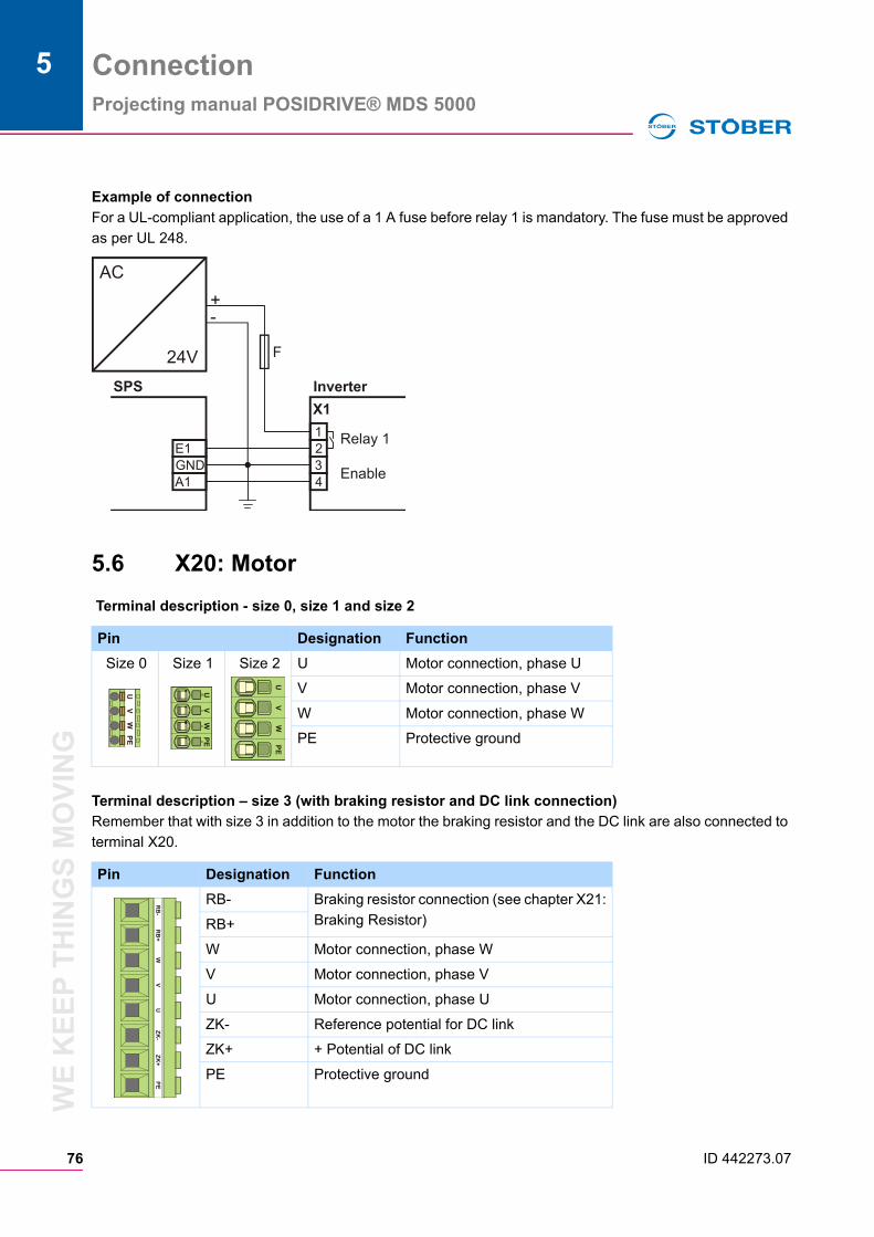
Connection
76
Projecting manual POSIDRIVE® MDS 5000
5W
E K
EE
P T
HIN
GS
MO
VIN
G
Example of connection
For a UL-compliant application, the use of a 1 A fuse before relay 1 is mandatory. The fuse must be approved
as per UL 248.
5.6 X20: Motor
Terminal description - size 0, size 1 and size 2
Terminal description – size 3 (with braking resistor and DC link connection)
Remember that with size 3 in addition to the motor the braking resistor and the DC link are also connected to
terminal X20.
Pin Designation Function
Size 0 Size 1 Size 2 U Motor connection, phase U
V Motor connection, phase V
W Motor connection, phase W
PE Protective ground
Pin Designation Function
RB- Braking resistor connection (see chapter X21:
Braking Resistor)RB+
W Motor connection, phase W
V Motor connection, phase V
U Motor connection, phase U
ZK- Reference potential for DC link
ZK+ + Potential of DC link
PE Protective ground
1
3GND2E1
4A1
X1
InverterSPS
Relay 1
Enable
AC
24V
-+
F
UV
WP
E
UV
WP
E
UV
WP
E
RB
-R
B+
WV
UZ
K-
ZK
+P
E
ID 442273.07
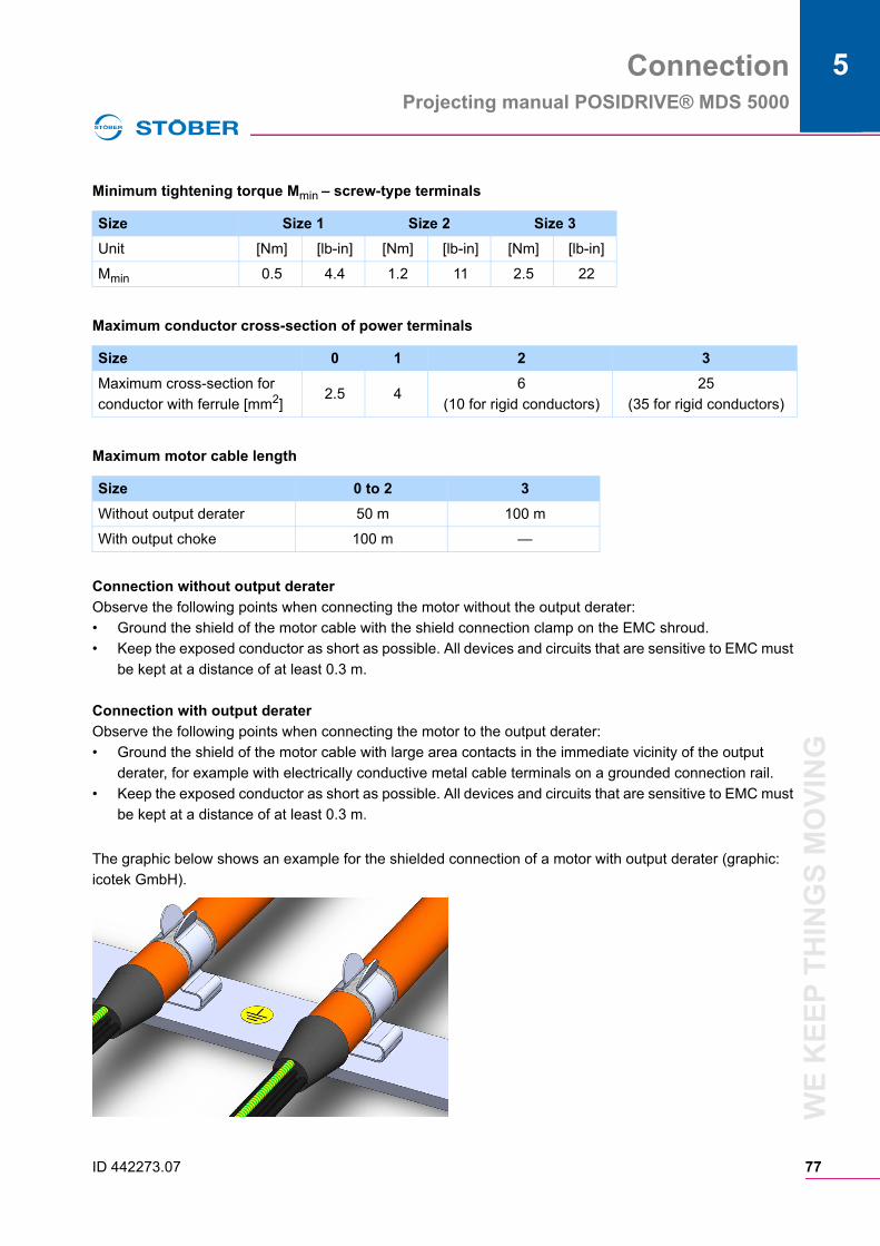
ConnectionProjecting manual POSIDRIVE® MDS 5000
WE
KE
EP
TH
ING
S M
OV
ING
5
Minimum tightening torque Mmin – screw-type terminals
Maximum conductor cross-section of power terminals
Maximum motor cable length
Connection without output derater
Observe the following points when connecting the motor without the output derater:
• Ground the shield of the motor cable with the shield connection clamp on the EMC shroud.
• Keep the exposed conductor as short as possible. All devices and circuits that are sensitive to EMC must
be kept at a distance of at least 0.3 m.
Connection with output derater
Observe the following points when connecting the motor to the output derater:
• Ground the shield of the motor cable with large area contacts in the immediate vicinity of the output
derater, for example with electrically conductive metal cable terminals on a grounded connection rail.
• Keep the exposed conductor as short as possible. All devices and circuits that are sensitive to EMC must
be kept at a distance of at least 0.3 m.
The graphic below shows an example for the shielded connection of a motor with output derater (graphic:
icotek GmbH).
Size Size 1 Size 2 Size 3
Unit [Nm] [lb-in] [Nm] [lb-in] [Nm] [lb-in]
Mmin 0.5 4.4 1.2 11 2.5 22
Size 0 1 2 3
Maximum cross-section for
conductor with ferrule [mm2]2.5 4
6
(10 for rigid conductors)
25
(35 for rigid conductors)
Size 0 to 2 3
Without output derater 50 m 100 m
With output choke 100 m —
ID 442273.07 77
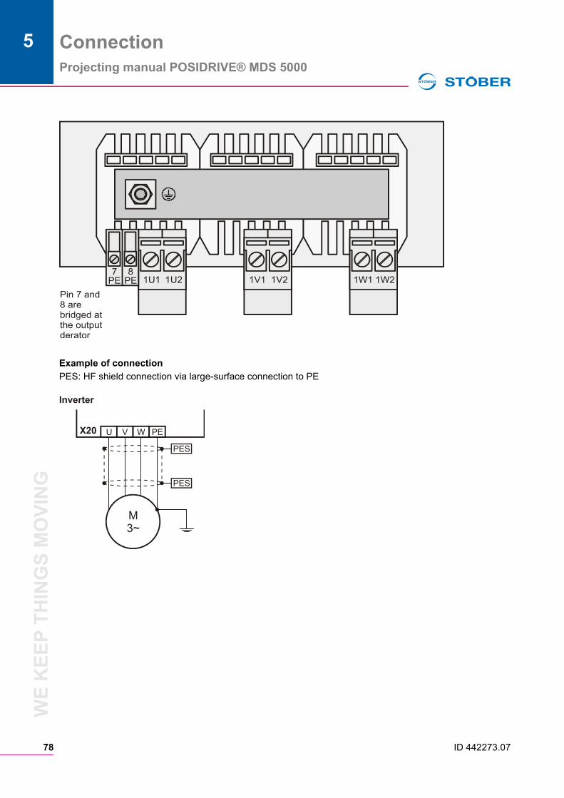
Connection
78
Projecting manual POSIDRIVE® MDS 5000
5W
E K
EE
P T
HIN
GS
MO
VIN
G
Example of connection
PES: HF shield connection via large-surface connection to PE
Pin 7 and8 arebridged atthe outputderator
1U1 1U2 1V1 1V2 1W1 1W27
PE8
PE
U V W PEX20
Inverter
PES
PES
M3~
ID 442273.07
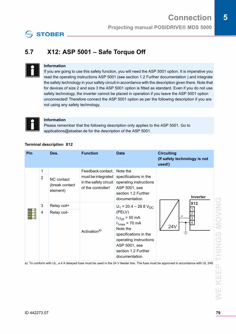
ConnectionProjecting manual POSIDRIVE® MDS 5000
WE
KE
EP
TH
ING
S M
OV
ING
5
5.7 X12: ASP 5001 – Safe Torque Off
Terminal description X12
Information
If you are going to use this safety function, you will need the ASP 5001 option. It is imperative you
read the operating instructions ASP 5001 (see section 1.2 Further documentation ) and integrate
the safety technology in your safety circuit in accordance with the description given there. Note that
for devices of size 2 and size 3 the ASP 5001 option is fitted as standard. Even if you do not use
safety technology, the inverter cannot be placed in operation if you leave the ASP 5001 option
unconnected! Therefore connect the ASP 5001 option as per the following description if you are
not using any safety technology.
Information
Please remember that the following description only applies to the ASP 5001. Go to
[email protected] for the description of the ASP 5001.
Pin Des. Function Data Circuiting (If safety technology is not
used!)
1
NC contact
(break contact
element)
Feedback contact;
must be integrated
in the safety circuit
of the controller!
Note the
specifications in the
operating instructions
ASP 5001, see
section 1.2 Further
documentation.
2
3 Relay coil+
Activationa)
a) To conform with UL, a 4 A delayed fuse must be used in the 24 V feeder line. The fuse must be approved in accordance with UL 248.
U1 = 20.4 – 28.8 VDC
(PELV)
I1Typ = 50 mA
I1max = 70 mA
Note the
specifications in the
operating instructions
ASP 5001, see
section 1.2 Further
documentation.
4 Relay coil-
12
34 +
-
1234
X12
Inverter
24V
ID 442273.07 79
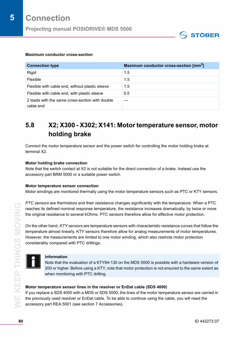
Connection
80
Projecting manual POSIDRIVE® MDS 5000
5W
E K
EE
P T
HIN
GS
MO
VIN
G
5.8 X2; X300 - X302; X141: Motor temperature sensor, motor holding brake
Connect the motor temperature sensor and the power switch for controlling the motor holding brake at
terminal X2.
Motor holding brake connection
Note that the switch contact at X2 is not suitable for the direct connection of a brake. Instead use the
accessory part BRM 5000 or a suitable power switch.
Motor temperature sensor connection
Motor windings are monitored thermally using the motor temperature sensors such as PTC or KTY sensors.
PTC sensors are thermistors and their resistance changes significantly with the temperature. When a PTC
reaches its defined nominal response temperature, the resistance increases dramatically, by twice or more
the original resistance to several kOhms. PTC sensors therefore allow for effective motor protection.
On the other hand, KTY sensors are temperature sensors with characteristic resistance curves that follow the
temperature almost linearly. KTY sensors therefore allow for analog measurements of motor temperatures.
However, the measurements are limited to one motor winding, which also restricts motor protection
considerably compared with PTC drillings.
Motor temperature sensor lines in the resolver or EnDat cable (SDS 4000)
If you replace a SDS 4000 with a MDS or SDS 5000, the lines of the motor temperature sensor are carried in
the previously used resolver or EnDat cable. To be able to continue using the cable, you will need the
accessory part REA 5001 (see section 7 Accessories).
Maximum conductor cross-section
Connection type Maximum conductor cross-section [mm2]
Rigid 1.5
Flexible 1.5
Flexible with cable end, without plastic sleeve 1.5
Flexible with cable end, with plastic sleeve 0.5
2 leads with the same cross-section with double
cable end
—
Information
Note that the evaluation of a KTY84-130 on the MDS 5000 is possible with a hardware version of
200 or higher. Before using a KTY, note that motor protection is not ensured to the same extent as
when monitoring with PTC drilling.
ID 442273.07
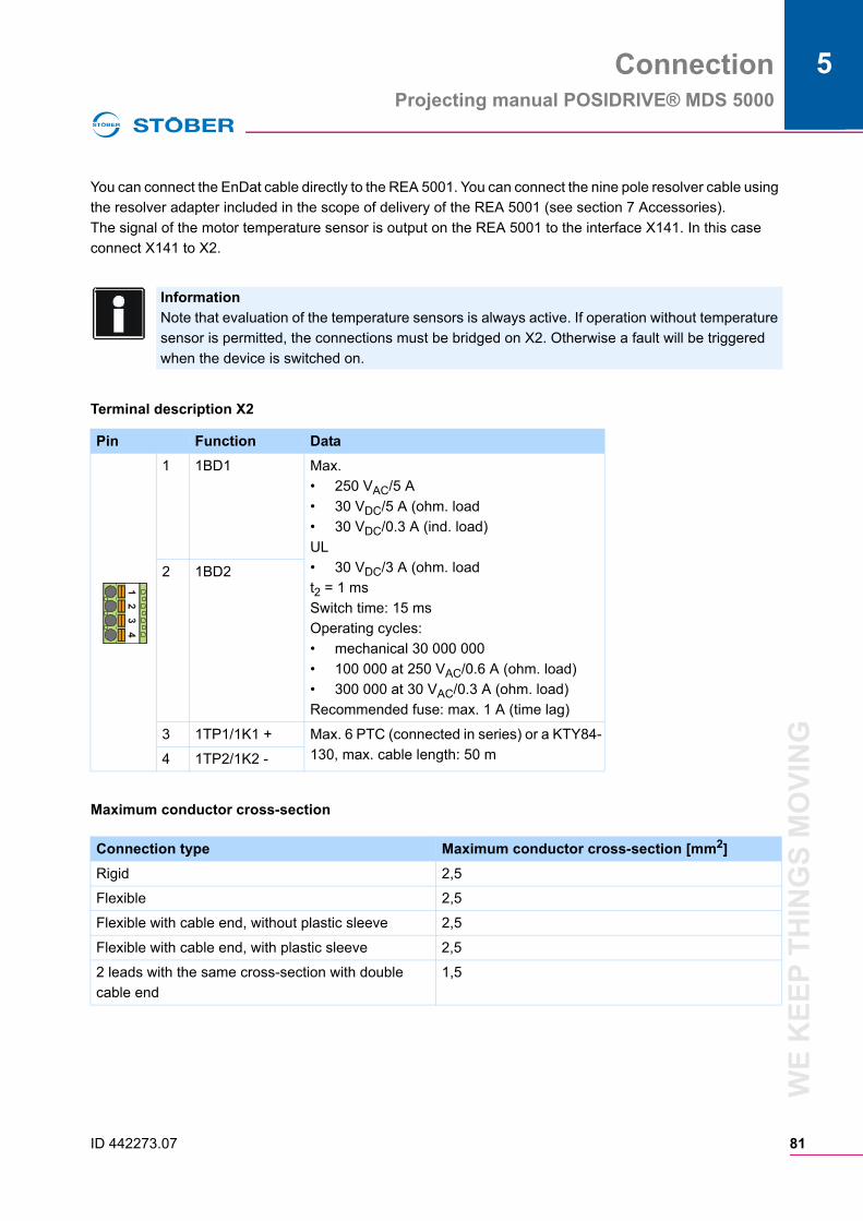
ConnectionProjecting manual POSIDRIVE® MDS 5000
WE
KE
EP
TH
ING
S M
OV
ING
5
You can connect the EnDat cable directly to the REA 5001. You can connect the nine pole resolver cable using
the resolver adapter included in the scope of delivery of the REA 5001 (see section 7 Accessories).
The signal of the motor temperature sensor is output on the REA 5001 to the interface X141. In this case
connect X141 to X2.
Terminal description X2
Information
Note that evaluation of the temperature sensors is always active. If operation without temperature
sensor is permitted, the connections must be bridged on X2. Otherwise a fault will be triggered
when the device is switched on.
Pin Function Data
1 1BD1
Max.
• 250 VAC/5 A
• 30 VDC/5 A (ohm. load
• 30 VDC/0.3 A (ind. load)
UL
• 30 VDC/3 A (ohm. load
t2 = 1 ms
Switch time: 15 ms
Operating cycles:
• mechanical 30 000 000
• 100 000 at 250 VAC/0.6 A (ohm. load)
• 300 000 at 30 VAC/0.3 A (ohm. load)
Recommended fuse: max. 1 A (time lag)
2 1BD2
3 1TP1/1K1 + Max. 6 PTC (connected in series) or a KTY84-
130, max. cable length: 50 m4 1TP2/1K2 -
Maximum conductor cross-section
Connection type Maximum conductor cross-section [mm2]
Rigid 2,5
Flexible 2,5
Flexible with cable end, without plastic sleeve 2,5
Flexible with cable end, with plastic sleeve 2,5
2 leads with the same cross-section with double
cable end
1,5
12
34
ID 442273.07 81
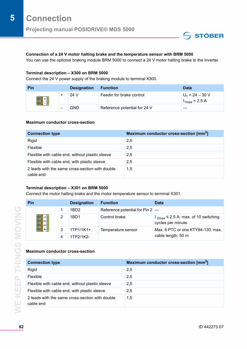
Connection
82
Projecting manual POSIDRIVE® MDS 5000
5W
E K
EE
P T
HIN
GS
MO
VIN
G
Connection of a 24 V motor halting brake and the temperature sensor with BRM 5000
You can use the optional braking module BRM 5000 to connect a 24 V motor halting brake to the inverter.
Terminal description – X300 on BRM 5000
Connect the 24 V power supply of the braking module to terminal X300.
Terminal description – X301 on BRM 5000
Connect the motor halting brake and the motor temperature sensor to terminal X301.
Pin Designation Function Data
+ 24 V Feedin for brake control U1 = 24 – 30 V
I1max = 2.5 A
– GND Reference potential for 24 V —
Maximum conductor cross-section
Connection type Maximum conductor cross-section [mm2]
Rigid 2,5
Flexible 2,5
Flexible with cable end, without plastic sleeve 2,5
Flexible with cable end, with plastic sleeve 2,5
2 leads with the same cross-section with double
cable end
1,5
Pin Designation Function Data
1 1BD2 Reference potential for Pin 2 —
2 1BD1 Control brake I 2max ≤ 2.5 A: max. of 10 switching
cycles per minute
3 1TP1/1K1+ Temperature sensor Max. 6 PTC or one KTY84-130, max.
cable length: 50 m4 1TP2/1K2-
Maximum conductor cross-section
Connection type Maximum conductor cross-section [mm2]
Rigid 2,5
Flexible 2,5
Flexible with cable end, without plastic sleeve 2,5
Flexible with cable end, with plastic sleeve 2,5
2 leads with the same cross-section with double
cable end
1,5
+1
23
4
ID 442273.07
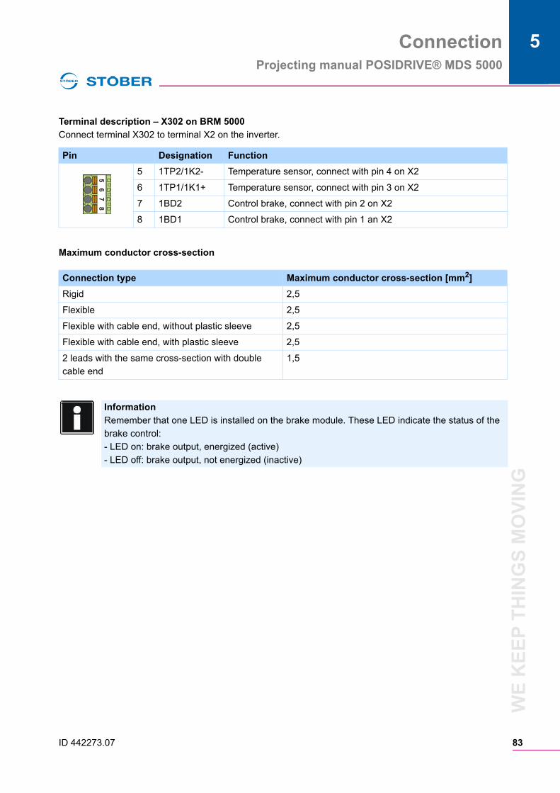
ConnectionProjecting manual POSIDRIVE® MDS 5000
WE
KE
EP
TH
ING
S M
OV
ING
5
Terminal description – X302 on BRM 5000
Connect terminal X302 to terminal X2 on the inverter.
Pin Designation Function
5 1TP2/1K2- Temperature sensor, connect with pin 4 on X2
6 1TP1/1K1+ Temperature sensor, connect with pin 3 on X2
7 1BD2 Control brake, connect with pin 2 on X2
8 1BD1 Control brake, connect with pin 1 an X2
Maximum conductor cross-section
Connection type Maximum conductor cross-section [mm2]
Rigid 2,5
Flexible 2,5
Flexible with cable end, without plastic sleeve 2,5
Flexible with cable end, with plastic sleeve 2,5
2 leads with the same cross-section with double
cable end
1,5
56
78
Information
Remember that one LED is installed on the brake module. These LED indicate the status of the
brake control:
- LED on: brake output, energized (active)
- LED off: brake output, not energized (inactive)
ID 442273.07 83
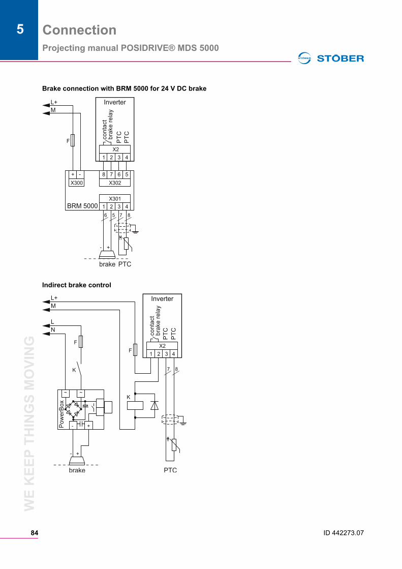
Connection
84
Projecting manual POSIDRIVE® MDS 5000
5W
E K
EE
P T
HIN
GS
MO
VIN
G
Brake connection with BRM 5000 for 24 V DC brake
Indirect brake control
cont
act
PT
CP
TC
Inverterbr
ake
re
lay
brake PTC
BRM 5000
X300 X302
X301
X2
L+M
+
+
-
-
8 7 6 5
1 2 3 4
1 2 3 4
F
7 86 5
Inverter
+-
X2
cont
act
PT
CP
TC
bra
ke r
elay
L+M
LN
K
F
F
K
1 2 3 4
brake PTC
7 8
Pow
erB
ox
~ ~
- +
ID 442273.07
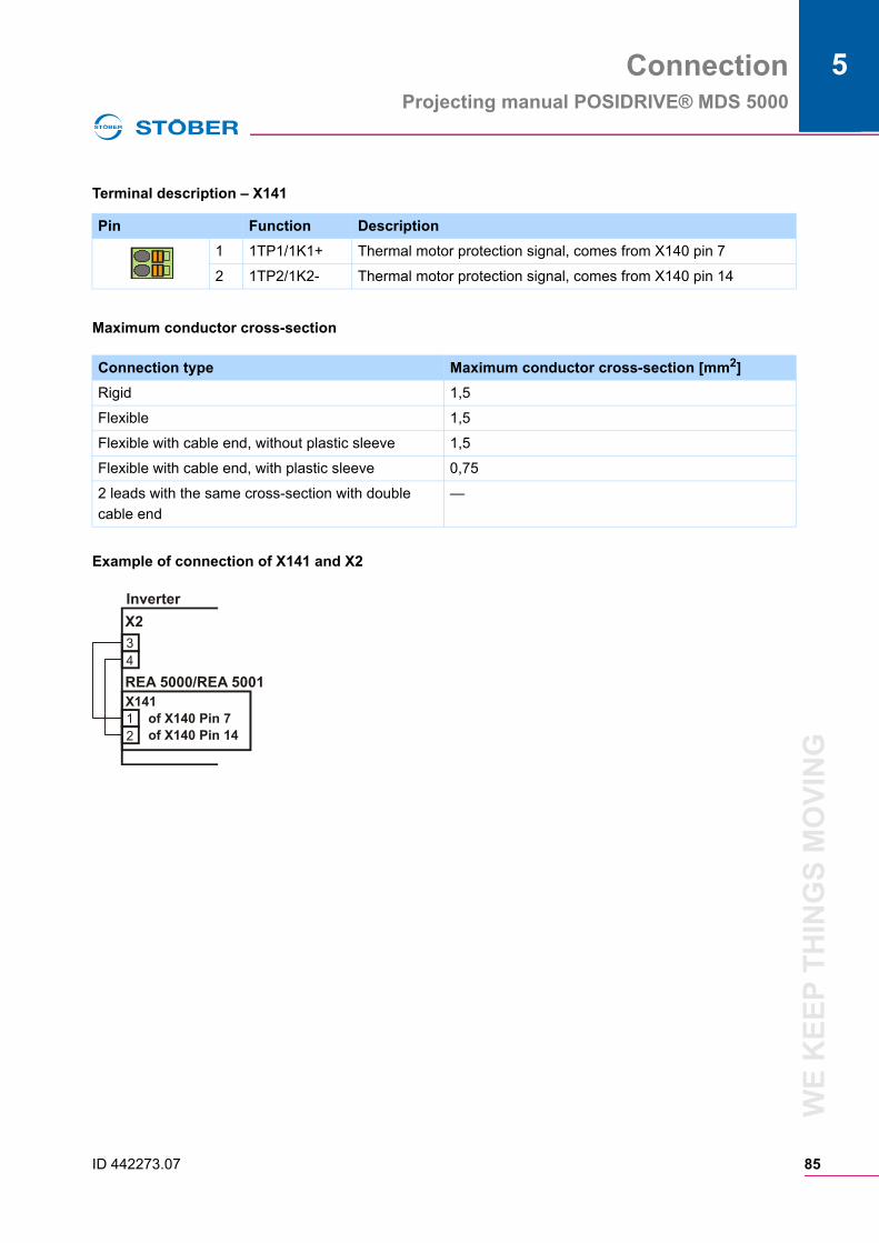
ConnectionProjecting manual POSIDRIVE® MDS 5000
WE
KE
EP
TH
ING
S M
OV
ING
5
Terminal description – X141
Example of connection of X141 and X2
Pin Function Description
1 1TP1/1K1+ Thermal motor protection signal, comes from X140 pin 7
2 1TP2/1K2- Thermal motor protection signal, comes from X140 pin 14
Maximum conductor cross-section
Connection type Maximum conductor cross-section [mm2]
Rigid 1,5
Flexible 1,5
Flexible with cable end, without plastic sleeve 1,5
Flexible with cable end, with plastic sleeve 0,75
2 leads with the same cross-section with double
cable end
—
3
1
4
2
X2
X141
REA 5000/REA 5001
Inverter
of X140 Pin 7of X140 Pin 14
ID 442273.07 85
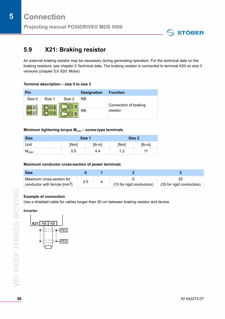
Connection
86
Projecting manual POSIDRIVE® MDS 5000
5W
E K
EE
P T
HIN
GS
MO
VIN
G
5.9 X21: Braking resistor
An external braking resistor may be necessary during generating operation. For the technical data on the
braking resistors, see chapter 3 Technical data. The braking resistor is connected to terminal X20 on size 3
versions (chapter 5.6 X20: Motor).
Terminal description – size 0 to size 2
Minimum tightening torque Mmin – screw-type terminals
Maximum conductor cross-section of power terminals
Example of connection
Use a shielded cable for cables longer than 30 cm between braking resistor and device.
Pin Designation Function
Size 0 Size 1 Size 2 RB
Connection of braking
resistorRB
Size Size 1 Size 2
Unit [Nm] [lb-in] [Nm] [lb-in]
Mmin 0.5 4.4 1.2 11
Size 0 1 2 3
Maximum cross-section for
conductor with ferrule [mm2]2.5 4
6
(10 for rigid conductors)
25
(35 for rigid conductors)
RB
RB
RB
RB
RB
RB
RB RBX21
Inverter
PES
PES
ID 442273.07
ConnectionProjecting manual POSIDRIVE® MDS 5000
WE
KE
EP
TH
ING
S M
OV
ING
5
5.10 X22: DC link coupling
When you have axes in your system which operate in combination and are continuously regenerative and
motor-driven, the DC link coupling may offer advantages. The DC link coupling takes the excess power and
offers it to other axes as drive power instead of converting it into heat via a braking resistor. Remember that
you will need a braking resistor to absorb the power peaks when all drives in the DC link coupling brake at the
same time.
DANGER!
Danger of device damage! When single-phase and three-phase devices are coupled, the single-phase
devices will be destroyed.
Only use three-phase devices for the DC link coupling!
NOTICE
Danger of device damage!
Because the failure of one device could damage other devices, failure of a device must cause the entire DC
link compound system to be disconnected from the power supply.
Make a note of the wiring and parameterization of relay 1 in Section Principal circuit diagram (X1.1 and
X1.2).
After a failure, replace all the devices in a group.
Information
Remember that the DC link coupling described here can only be used with the device families MDS
5000, SDS 5000 and FDS 5000.
Information
Remember that the parameter A38 DC power-input must be set before the DC link coupling can
function correctly:
Group 1: A38 = 0: inactive
Groups 2 and 3: A38 = 1: active
See the description of the parameter.
ID 442273.07 87
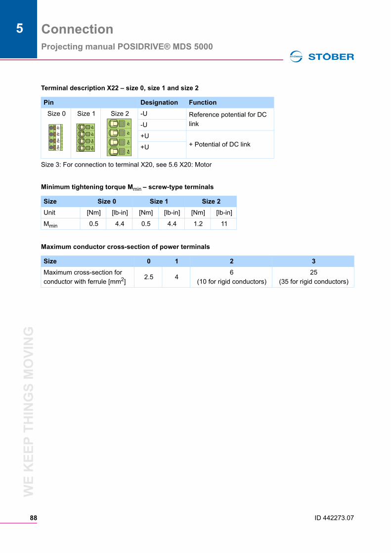
Connection
88
Projecting manual POSIDRIVE® MDS 5000
5W
E K
EE
P T
HIN
GS
MO
VIN
G
Terminal description X22 – size 0, size 1 and size 2
Size 3: For connection to terminal X20, see 5.6 X20: Motor
Minimum tightening torque Mmin – screw-type terminals
Maximum conductor cross-section of power terminals
Pin Designation Function
Size 0 Size 1 Size 2 -U Reference potential for DC
link-U
+U+ Potential of DC link+U
Size Size 0 Size 1 Size 2
Unit [Nm] [lb-in] [Nm] [lb-in] [Nm] [lb-in]
Mmin 0.5 4.4 0.5 4.4 1.2 11
Size 0 1 2 3
Maximum cross-section for
conductor with ferrule [mm2]2.5 4
6
(10 for rigid conductors)
25
(35 for rigid conductors)
-U-U
+U
+U
-U-U
+U
+U
-U-U
+U
+U
ID 442273.07
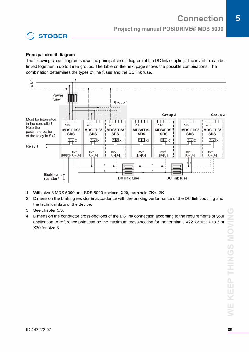
ConnectionProjecting manual POSIDRIVE® MDS 5000
WE
KE
EP
TH
ING
S M
OV
ING
5
Principal circuit diagram
The following circuit diagram shows the principal circuit diagram of the DC link coupling. The inverters can be
linked together in up to three groups. The table on the next page shows the possible combinations. The
combination determines the types of line fuses and the DC link fuse.
1 With size 3 MDS 5000 and SDS 5000 devices: X20, terminals ZK+, ZK-.
2 Dimension the braking resistor in accordance with the braking performance of the DC link coupling and
the technical data of the device.
3 See chapter 5.3.
4 Dimension the conductor cross-sections of the DC link connection according to the requirements of your
application. A reference point can be the maximum cross-section for the terminals X22 for size 0 to 2 or
X20 for size 3.
MDS/FDS/SDS
MDS/FDS/SDS
MDS/FDS/SDS
MDS/FDS/SDS
MDS/FDS/SDS
MDS/FDS/SDS
MDS/FDS/SDS
X10 X10 X10 X10X10 X10 X10
X1 X1 X1 X1X1 X1 X1
X221 X221 X221X221 X221 X221
U+RB RB U+ U+ U+U+ U+ U+U- U- U- U-U- U- U-
1 1 1 11 1 12 2 2 22 2 2
Powerfuse3
Brakingresistor2
2
L1L2L3PE
Group 1
Group 2
DC link fuse DC link fuse
Group 3
Relay 1
Must be integratedin the controller!Note the parameterizationof the relay in .F10
4
4
4
4
4 4
ID 442273.07 89
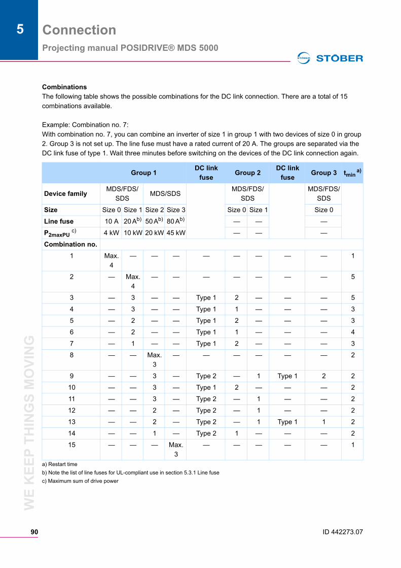
Connection
90
Projecting manual POSIDRIVE® MDS 5000
5W
E K
EE
P T
HIN
GS
MO
VIN
G
Combinations
The following table shows the possible combinations for the DC link connection. There are a total of 15
combinations available.
Example: Combination no. 7:
With combination no. 7, you can combine an inverter of size 1 in group 1 with two devices of size 0 in group
2. Group 3 is not set up. The line fuse must have a rated current of 20 A. The groups are separated via the
DC link fuse of type 1. Wait three minutes before switching on the devices of the DC link connection again.
Group 1DC link
fuseGroup 2
DC link
fuseGroup 3 tmin a)
a) Restart time
Device familyMDS/FDS/
SDSMDS/SDS
MDS/FDS/
SDS
MDS/FDS/
SDS
Size Size 0 Size 1 Size 2 Size 3 Size 0 Size 1 Size 0
Line fuse 10 A 20 Ab)
b) Note the list of line fuses for UL-compliant use in section 5.3.1 Line fuse
50 Ab) 80 Ab) — — —
P2maxPU c)
c) Maximum sum of drive power
4 kW 10 kW 20 kW 45 kW — — —
Combination no.
1 Max.
4
— — — — — — — — 1
2 — Max.
4
— — — — — — — 5
3 — 3 — — Type 1 2 — — — 5
4 — 3 — — Type 1 1 — — — 3
5 — 2 — — Type 1 2 — — — 3
6 — 2 — — Type 1 1 — — — 4
7 — 1 — — Type 1 2 — — — 3
8 — — Max.
3
— — — — — — 2
9 — — 3 — Type 2 — 1 Type 1 2 2
10 — — 3 — Type 1 2 — — — 2
11 — — 3 — Type 2 — 1 — — 2
12 — — 2 — Type 2 — 1 — — 2
13 — — 2 — Type 2 — 1 Type 1 1 2
14 — — 1 — Type 2 1 — — — 2
15 — — — Max.
3
— — — — — 1
ID 442273.07
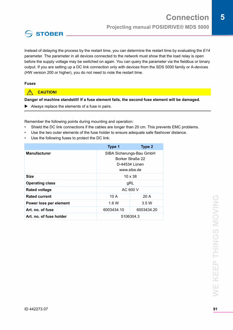
ConnectionProjecting manual POSIDRIVE® MDS 5000
WE
KE
EP
TH
ING
S M
OV
ING
5
Instead of delaying the process by the restart time, you can determine the restart time by evaluating the E14
parameter. The parameter in all devices connected to the network must show that the load relay is open
before the supply voltage may be switched on again. You can query the parameter via the fieldbus or binary
output. If you are setting up a DC link connection only with devices from the SDS 5000 family or A-devices
(HW version 200 or higher), you do not need to note the restart time.
Fuses
CAUTION!
Danger of machine standstill! If a fuse element fails, the second fuse element will be damaged.
Always replace the elements of a fuse in pairs.
Remember the following points during mounting and operation:
• Shield the DC link connections if the cables are longer than 20 cm. This prevents EMC problems.
• Use the two outer elements of the fuse holder to ensure adequate safe flashover distance.
• Use the following fuses to protect the DC link:
Type 1 Type 2
Manufacturer SIBA Sicherungs-Bau GmbH
Borker Straße 22
D-44534 Lünen
www.siba.de
Size 10 x 38
Operating class gRL
Rated voltage AC 600 V
Rated current 10 A 20 A
Power loss per element 1.6 W 3.5 W
Art. no. of fuse 6003434.10 6003434.20
Art. no. of fuse holder 5106304.3
ID 442273.07 91

Connection
92
Projecting manual POSIDRIVE® MDS 5000
5W
E K
EE
P T
HIN
GS
MO
VIN
G
5.11 X100 - X103: Analog and binary signals
Below are the prerequisites for connecting analog and binary signals:
• SEA 5001
• REA 5001
• XEA 5001
WARNING!
Danger of faulty machine behavior due to EMC faults!
Use exclusively cables up to 30 m in length for analog and binary inputs and outputs (AE, AA, BE, BA)!
Terminal description X100 – SEA 5001, REA 5001, XEA 5001
NOTICE
Machine movement by unexpected reference value
The inverter detects a reference value setting of +5 V for an unconnected analog input.
Always operate the inverter with a connected analog input.
Information
Note that the sampling time of the inputs and the refresh rate of the outputs correspond to the cycle
time set in parameter A150.
For time critical functions such as a print mark control, a time stamp is also available for the binary
inputs.
If BE encoders or BA encoder simulation is used, the sampling time and refresh rate is
independent of the set cycle time (see section 5.12.4 BE encoder and BA encoder simulation).
General specification
Maximum cable length 30 m, shielded
ID 442273.07
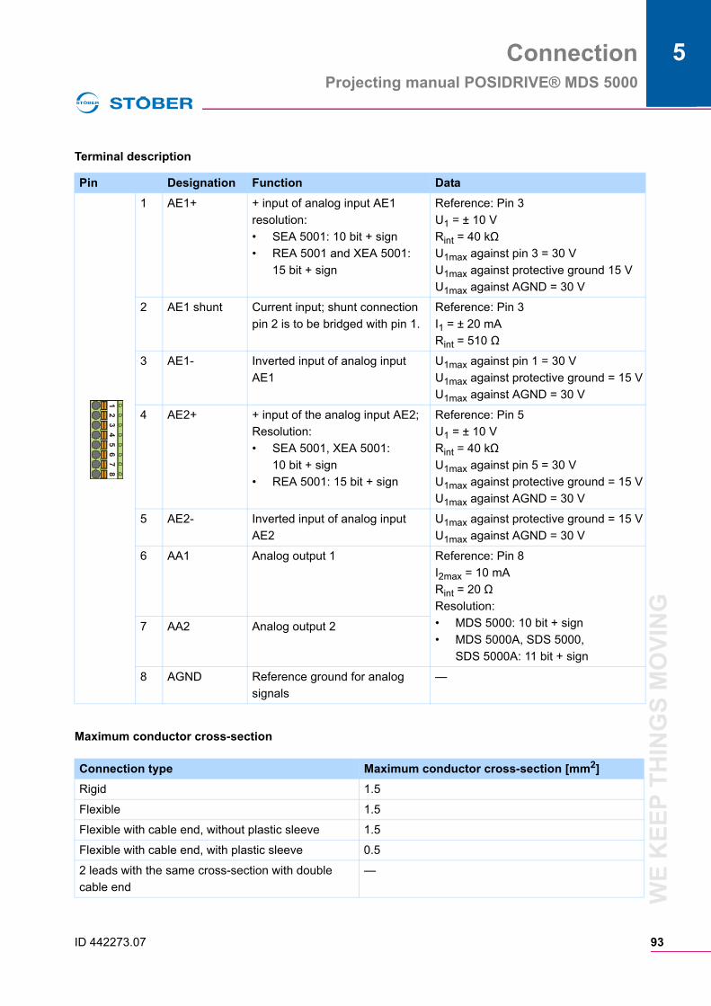
ConnectionProjecting manual POSIDRIVE® MDS 5000
WE
KE
EP
TH
ING
S M
OV
ING
5
Terminal description
Pin Designation Function Data
1 AE1+ + input of analog input AE1 resolution:
• SEA 5001: 10 bit + sign
• REA 5001 and XEA 5001: 15 bit + sign
Reference: Pin 3
U1 = ± 10 V
Rint = 40 kΩ
U1max against pin 3 = 30 V
U1max against protective ground 15 V
U1max against AGND = 30 V
2 AE1 shunt Current input; shunt connection
pin 2 is to be bridged with pin 1.
Reference: Pin 3
I1 = ± 20 mA
Rint = 510 Ω
3 AE1- Inverted input of analog input
AE1
U1max against pin 1 = 30 VU1max against protective ground = 15 VU1max against AGND = 30 V
4 AE2+ + input of the analog input AE2;
Resolution:
• SEA 5001, XEA 5001: 10 bit + sign
• REA 5001: 15 bit + sign
Reference: Pin 5
U1 = ± 10 VRint = 40 kΩ U1max against pin 5 = 30 VU1max against protective ground = 15 VU1max against AGND = 30 V
5 AE2- Inverted input of analog input
AE2
U1max against protective ground = 15 VU1max against AGND = 30 V
6 AA1 Analog output 1
Reference: Pin 8
I2max = 10 mA
Rint = 20 Ω
Resolution:
• MDS 5000: 10 bit + sign
• MDS 5000A, SDS 5000,
SDS 5000A: 11 bit + sign
7 AA2 Analog output 2
8 AGND Reference ground for analog
signals
—
12
34
56
78
Maximum conductor cross-section
Connection type Maximum conductor cross-section [mm2]
Rigid 1.5
Flexible 1.5
Flexible with cable end, without plastic sleeve 1.5
Flexible with cable end, with plastic sleeve 0.5
2 leads with the same cross-section with double
cable end
—
ID 442273.07 93
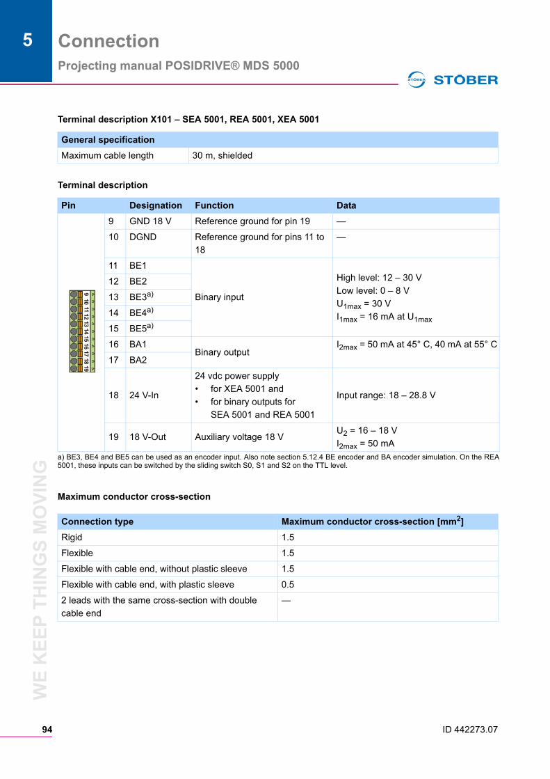
Connection
94
Projecting manual POSIDRIVE® MDS 5000
5W
E K
EE
P T
HIN
GS
MO
VIN
G
Terminal description X101 – SEA 5001, REA 5001, XEA 5001
Terminal description
General specification
Maximum cable length 30 m, shielded
Pin Designation Function Data
9 GND 18 V Reference ground for pin 19 —
10 DGND Reference ground for pins 11 to
18
—
11 BE1
Binary input
High level: 12 – 30 V
Low level: 0 – 8 V
U1max = 30 V
I1max = 16 mA at U1max
12 BE2
13 BE3a)
14 BE4a)
15 BE5a)
16 BA1Binary output
I2max = 50 mA at 45° C, 40 mA at 55° C
17 BA2
18 24 V-In
24 vdc power supply
• for XEA 5001 and
• for binary outputs for
SEA 5001 and REA 5001
Input range: 18 – 28.8 V
19 18 V-Out Auxiliary voltage 18 VU2 = 16 – 18 V
I2max = 50 mA
a) BE3, BE4 and BE5 can be used as an encoder input. Also note section 5.12.4 BE encoder and BA encoder simulation. On the REA 5001, these inputs can be switched by the sliding switch S0, S1 and S2 on the TTL level.
910
1112
1314
1516
1718
19
Maximum conductor cross-section
Connection type Maximum conductor cross-section [mm2]
Rigid 1.5
Flexible 1.5
Flexible with cable end, without plastic sleeve 1.5
Flexible with cable end, with plastic sleeve 0.5
2 leads with the same cross-section with double
cable end
—
ID 442273.07
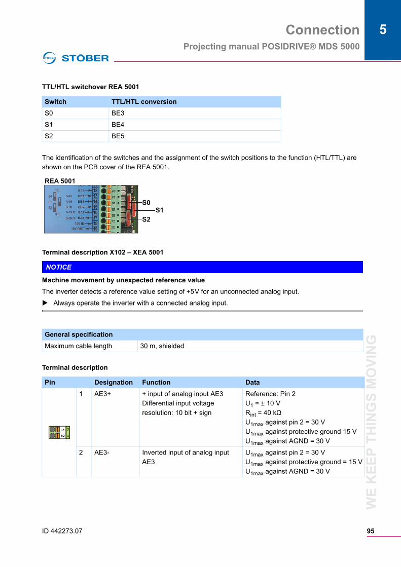
ConnectionProjecting manual POSIDRIVE® MDS 5000
WE
KE
EP
TH
ING
S M
OV
ING
5
TTL/HTL switchover REA 5001
The identification of the switches and the assignment of the switch positions to the function (HTL/TTL) are
shown on the PCB cover of the REA 5001.
Terminal description X102 – XEA 5001
NOTICE
Machine movement by unexpected reference value
The inverter detects a reference value setting of +5 V for an unconnected analog input.
Always operate the inverter with a connected analog input.
Terminal description
Switch TTL/HTL conversion
S0 BE3
S1 BE4
S2 BE5
General specification
Maximum cable length 30 m, shielded
REA 5001
S0S1
S2
Pin Designation Function Data
1 AE3+ + input of analog input AE3 Differential input voltage
resolution: 10 bit + sign
Reference: Pin 2
U1 = ± 10 V
Rint = 40 kΩ
U1max against pin 2 = 30 V
U1max against protective ground 15 V
U1max against AGND = 30 V
2 AE3- Inverted input of analog input
AE3
U1max against pin 2 = 30 V U1max against protective ground = 15 V
U1max against AGND = 30 V
12
ID 442273.07 95
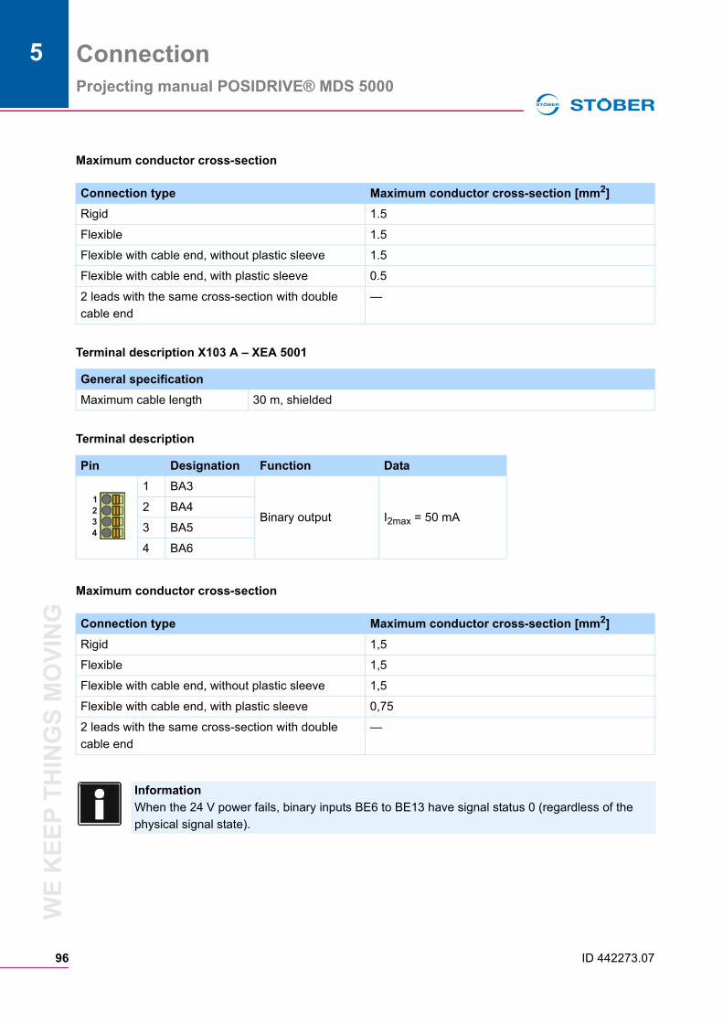
Connection
96
Projecting manual POSIDRIVE® MDS 5000
5W
E K
EE
P T
HIN
GS
MO
VIN
G
Terminal description X103 A – XEA 5001
Terminal description
Maximum conductor cross-section
Connection type Maximum conductor cross-section [mm2]
Rigid 1.5
Flexible 1.5
Flexible with cable end, without plastic sleeve 1.5
Flexible with cable end, with plastic sleeve 0.5
2 leads with the same cross-section with double
cable end
—
General specification
Maximum cable length 30 m, shielded
Pin Designation Function Data
1 BA3
Binary output I2max = 50 mA 2 BA4
3 BA5
4 BA6
Maximum conductor cross-section
Connection type Maximum conductor cross-section [mm2]
Rigid 1,5
Flexible 1,5
Flexible with cable end, without plastic sleeve 1,5
Flexible with cable end, with plastic sleeve 0,75
2 leads with the same cross-section with double
cable end
—
4
123
Information
When the 24 V power fails, binary inputs BE6 to BE13 have signal status 0 (regardless of the
physical signal state).
ID 442273.07
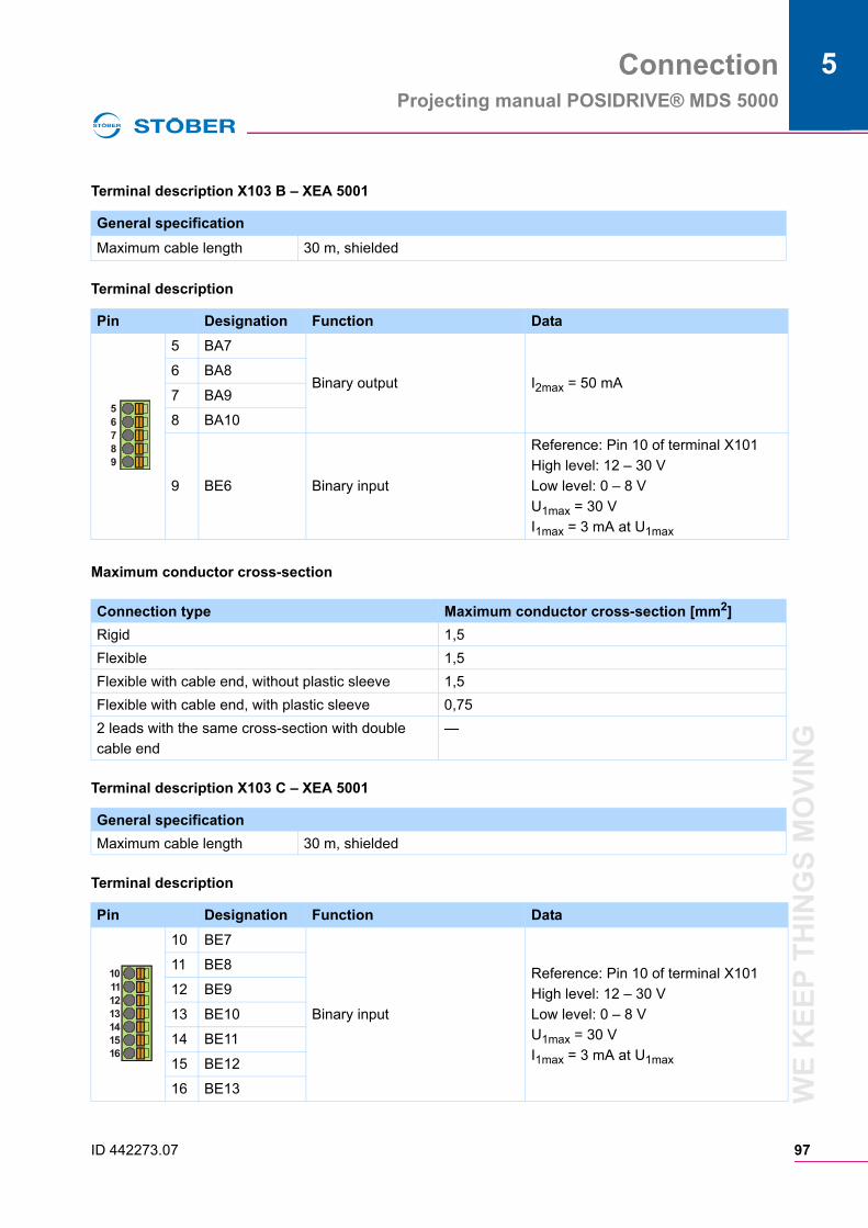
ConnectionProjecting manual POSIDRIVE® MDS 5000
WE
KE
EP
TH
ING
S M
OV
ING
5
Terminal description X103 B – XEA 5001
Terminal description
Terminal description X103 C – XEA 5001
Terminal description
General specification
Maximum cable length 30 m, shielded
Pin Designation Function Data
5 BA7
Binary output I2max = 50 mA 6 BA8
7 BA9
8 BA10
9 BE6 Binary input
Reference: Pin 10 of terminal X101
High level: 12 – 30 V
Low level: 0 – 8 V
U1max = 30 V
I1max = 3 mA at U1max
9
78
56
Maximum conductor cross-section
Connection type Maximum conductor cross-section [mm2]
Rigid 1,5
Flexible 1,5
Flexible with cable end, without plastic sleeve 1,5
Flexible with cable end, with plastic sleeve 0,75
2 leads with the same cross-section with double
cable end
—
General specification
Maximum cable length 30 m, shielded
Pin Designation Function Data
10 BE7
Binary input
Reference: Pin 10 of terminal X101
High level: 12 – 30 V
Low level: 0 – 8 V
U1max = 30 V
I1max = 3 mA at U1max
11 BE8
12 BE9
13 BE10
14 BE11
15 BE12
16 BE13
10111213141516
ID 442273.07 97
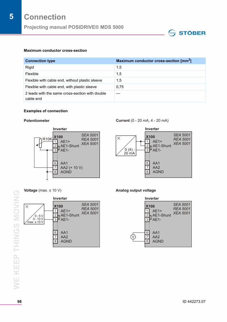
Connection
98
Projecting manual POSIDRIVE® MDS 5000
5W
E K
EE
P T
HIN
GS
MO
VIN
G
Examples of connection
Maximum conductor cross-section
Connection type Maximum conductor cross-section [mm2]
Rigid 1,5
Flexible 1,5
Flexible with cable end, without plastic sleeve 1,5
Flexible with cable end, with plastic sleeve 0,75
2 leads with the same cross-section with double
cable end
—
123
678
X100
Inverter
Potentiometer
R10KAE1+
AA1
AE1-Shunt
AA2 (+ 10 V)
AE1-
AGND
SEA 5001REA 5001XEA 5001
123
678
X100
Current (0 - 20 mA, 4 - 20 mA)
Inverter
AE1+
AA1
AE1-Shunt
AA2
AE1-
AGND
SEA 5001REA 5001XEA 5001
0 (4) -20 mA
123
678
X100
Inverter
Voltage max. ± 10 V)(
AE1+
AA1
AE1-Shunt
AA2
AE1-
AGND
SEA 5001REA 5001XEA 5001
0 - 5 V0 - 10 V
max. ± 10 V
123
678
X100
Inverter
Analog output voltage
AE1+
AA1
AE1-Shunt
AA2
AE1-
AGND
SEA 5001REA 5001XEA 5001
V
ID 442273.07
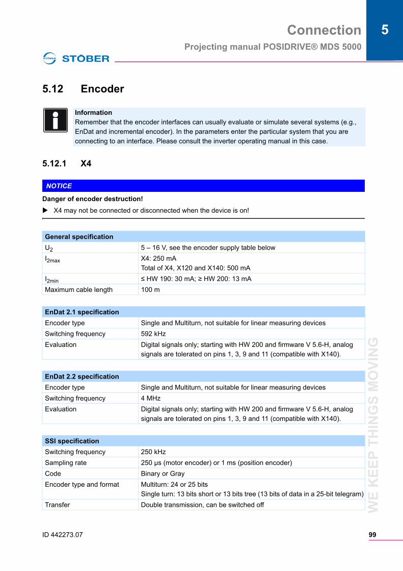
ConnectionProjecting manual POSIDRIVE® MDS 5000
WE
KE
EP
TH
ING
S M
OV
ING
5
5.12 Encoder
5.12.1 X4
NOTICE
Danger of encoder destruction!
X4 may not be connected or disconnected when the device is on!
Information
Remember that the encoder interfaces can usually evaluate or simulate several systems (e.g.,
EnDat and incremental encoder). In the parameters enter the particular system that you are
connecting to an interface. Please consult the inverter operating manual in this case.
General specification
U2 5 – 16 V, see the encoder supply table below
I2max X4: 250 mA
Total of X4, X120 and X140: 500 mA
I2min ≤ HW 190: 30 mA; ≥ HW 200: 13 mA
Maximum cable length 100 m
EnDat 2.1 specification
Encoder type Single and Multiturn, not suitable for linear measuring devices
Switching frequency 592 kHz
Evaluation Digital signals only; starting with HW 200 and firmware V 5.6-H, analog
signals are tolerated on pins 1, 3, 9 and 11 (compatible with X140).
EnDat 2.2 specification
Encoder type Single and Multiturn, not suitable for linear measuring devices
Switching frequency 4 MHz
Evaluation Digital signals only; starting with HW 200 and firmware V 5.6-H, analog
signals are tolerated on pins 1, 3, 9 and 11 (compatible with X140).
SSI specification
Switching frequency 250 kHz
Sampling rate 250 µs (motor encoder) or 1 ms (position encoder)
Code Binary or Gray
Encoder type and format Multiturn: 24 or 25 bits
Single turn: 13 bits short or 13 bits tree (13 bits of data in a 25-bit telegram)
Transfer Double transmission, can be switched off
ID 442273.07 99
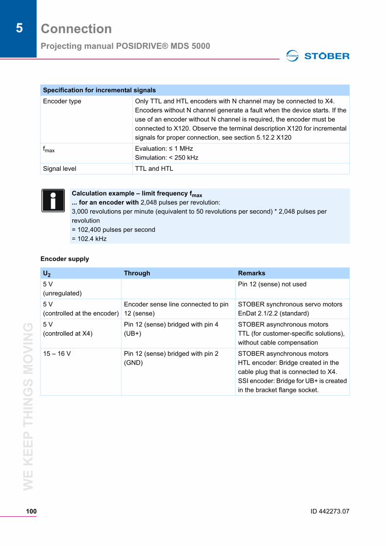
Connection
100
Projecting manual POSIDRIVE® MDS 5000
5W
E K
EE
P T
HIN
GS
MO
VIN
G
Encoder supply
Specification for incremental signals
Encoder type Only TTL and HTL encoders with N channel may be connected to X4.
Encoders without N channel generate a fault when the device starts. If the
use of an encoder without N channel is required, the encoder must be
connected to X120. Observe the terminal description X120 for incremental
signals for proper connection, see section 5.12.2 X120
fmax Evaluation: ≤ 1 MHz
Simulation: < 250 kHz
Signal level TTL and HTL
Calculation example – limit frequency fmax ... for an encoder with 2,048 pulses per revolution: 3,000 revolutions per minute (equivalent to 50 revolutions per second) * 2,048 pulses per
revolution= 102,400 pulses per second = 102.4 kHz
U2 Through Remarks
5 V (unregulated)
Pin 12 (sense) not used
5 V (controlled at the encoder)
Encoder sense line connected to pin
12 (sense)
STOBER synchronous servo motors
EnDat 2.1/2.2 (standard)
5 V(controlled at X4)
Pin 12 (sense) bridged with pin 4
(UB+)
STOBER asynchronous motors
TTL (for customer-specific solutions),without cable compensation
15 – 16 V Pin 12 (sense) bridged with pin 2
(GND)
STOBER asynchronous motors
HTL encoder: Bridge created in the
cable plug that is connected to X4.
SSI encoder: Bridge for UB+ is created
in the bracket flange socket.
ID 442273.07
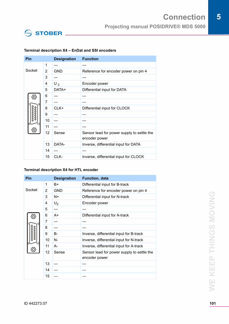
ConnectionProjecting manual POSIDRIVE® MDS 5000
WE
KE
EP
TH
ING
S M
OV
ING
5
Terminal description X4 – EnDat and SSI encoders
Terminal description X4 for HTL encoder
Pin Designation Function
Socket
1 — —
2 GND Reference for encoder power on pin 4
3 — —
4 U 2 Encoder power
5 DATA+ Differential input for DATA
6 — —
7 — —
8 CLK+ Differential input for CLOCK
9 — —
10 — —
11 — —
12 Sense Sensor lead for power supply to settle the
encoder power
13 DATA- Inverse, differential input for DATA
14 — —
15 CLK- Inverse, differential input for CLOCK
Pin Designation Function, data
Socket
1 B+ Differential input for B-track
2 GND Reference for encoder power on pin 4
3 N+ Differential input for N-track
4 U2 Encoder power
5 — —
6 A+ Differential input for A-track
7 — —
8 — —
9 B- Inverse, differential input for B-track
10 N- Inverse, differential input for N-track
11 A- Inverse, differential input for A-track
12 Sense Sensor lead for power supply to settle the
encoder power
13 — —
14 — —
15 — —
9
15
1
8
9
15
1
8
ID 442273.07 101
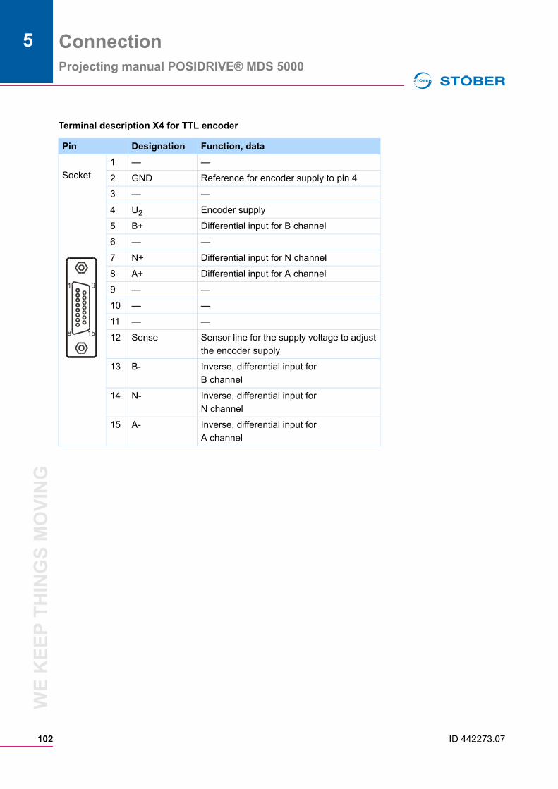
Connection
102
Projecting manual POSIDRIVE® MDS 5000
5W
E K
EE
P T
HIN
GS
MO
VIN
G
Terminal description X4 for TTL encoder
Pin Designation Function, data
Socket
1 — —
2 GND Reference for encoder supply to pin 4
3 — —
4 U2 Encoder supply
5 B+ Differential input for B channel
6 — —
7 N+ Differential input for N channel
8 A+ Differential input for A channel
9 — —
10 — —
11 — —
12 Sense Sensor line for the supply voltage to adjust
the encoder supply
13 B- Inverse, differential input for B channel
14 N- Inverse, differential input for N channel
15 A- Inverse, differential input for A channel
9
15
1
8
ID 442273.07
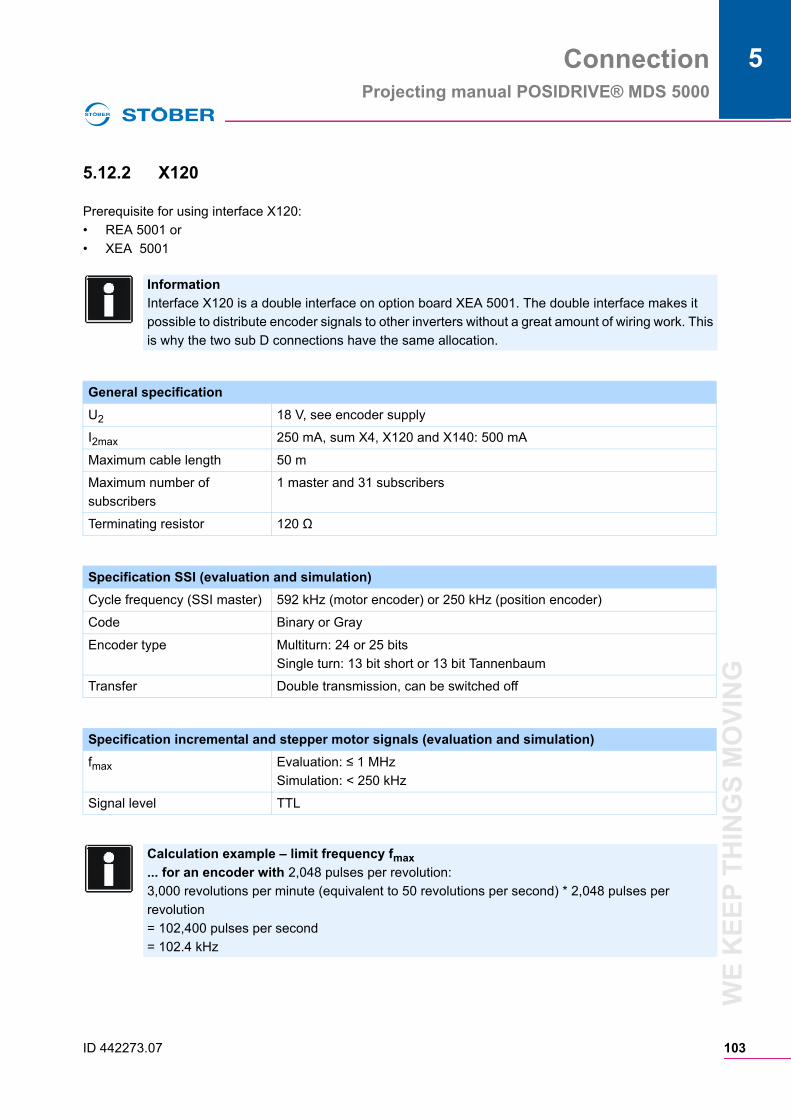
ConnectionProjecting manual POSIDRIVE® MDS 5000
WE
KE
EP
TH
ING
S M
OV
ING
5
5.12.2 X120
Prerequisite for using interface X120:
• REA 5001 or
• XEA 5001
Information
Interface X120 is a double interface on option board XEA 5001. The double interface makes it
possible to distribute encoder signals to other inverters without a great amount of wiring work. This
is why the two sub D connections have the same allocation.
General specification
U2 18 V, see encoder supply
I2max 250 mA, sum X4, X120 and X140: 500 mA
Maximum cable length 50 m
Maximum number of
subscribers
1 master and 31 subscribers
Terminating resistor 120 Ω
Specification SSI (evaluation and simulation)
Cycle frequency (SSI master) 592 kHz (motor encoder) or 250 kHz (position encoder)
Code Binary or Gray
Encoder type Multiturn: 24 or 25 bits
Single turn: 13 bit short or 13 bit Tannenbaum
Transfer Double transmission, can be switched off
Specification incremental and stepper motor signals (evaluation and simulation)
fmax Evaluation: ≤ 1 MHz
Simulation: < 250 kHz
Signal level TTL
Calculation example – limit frequency fmax ... for an encoder with 2,048 pulses per revolution: 3,000 revolutions per minute (equivalent to 50 revolutions per second) * 2,048 pulses per
revolution= 102,400 pulses per second = 102.4 kHz
ID 442273.07 103
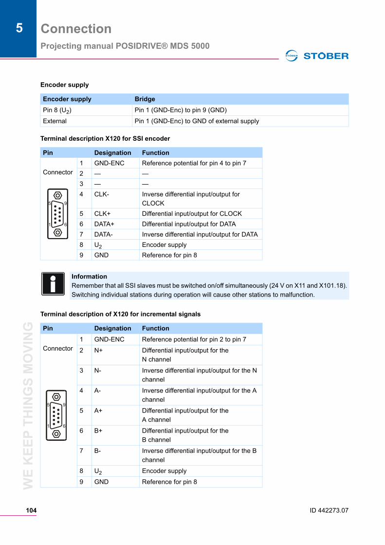
Connection
104
Projecting manual POSIDRIVE® MDS 5000
5W
E K
EE
P T
HIN
GS
MO
VIN
G
Encoder supply
Terminal description X120 for SSI encoder
Terminal description of X120 for incremental signals
Encoder supply Bridge
Pin 8 (U2) Pin 1 (GND-Enc) to pin 9 (GND)
External Pin 1 (GND-Enc) to GND of external supply
Pin Designation Function
Connector
1 GND-ENC Reference potential for pin 4 to pin 7
2 — —
3 — —
4 CLK- Inverse differential input/output for
CLOCK
5 CLK+ Differential input/output for CLOCK
6 DATA+ Differential input/output for DATA
7 DATA- Inverse differential input/output for DATA
8 U2 Encoder supply
9 GND Reference for pin 8
5
1
9
6
Information
Remember that all SSI slaves must be switched on/off simultaneously (24 V on X11 and X101.18).
Switching individual stations during operation will cause other stations to malfunction.
Pin Designation Function
Connector
1 GND-ENC Reference potential for pin 2 to pin 7
2 N+ Differential input/output for the N channel
3 N- Inverse differential input/output for the N
channel
4 A- Inverse differential input/output for the A
channel
5 A+ Differential input/output for the A channel
6 B+ Differential input/output for theB channel
7 B- Inverse differential input/output for the B
channel
8 U2 Encoder supply
9 GND Reference for pin 8
5
1
9
6
ID 442273.07
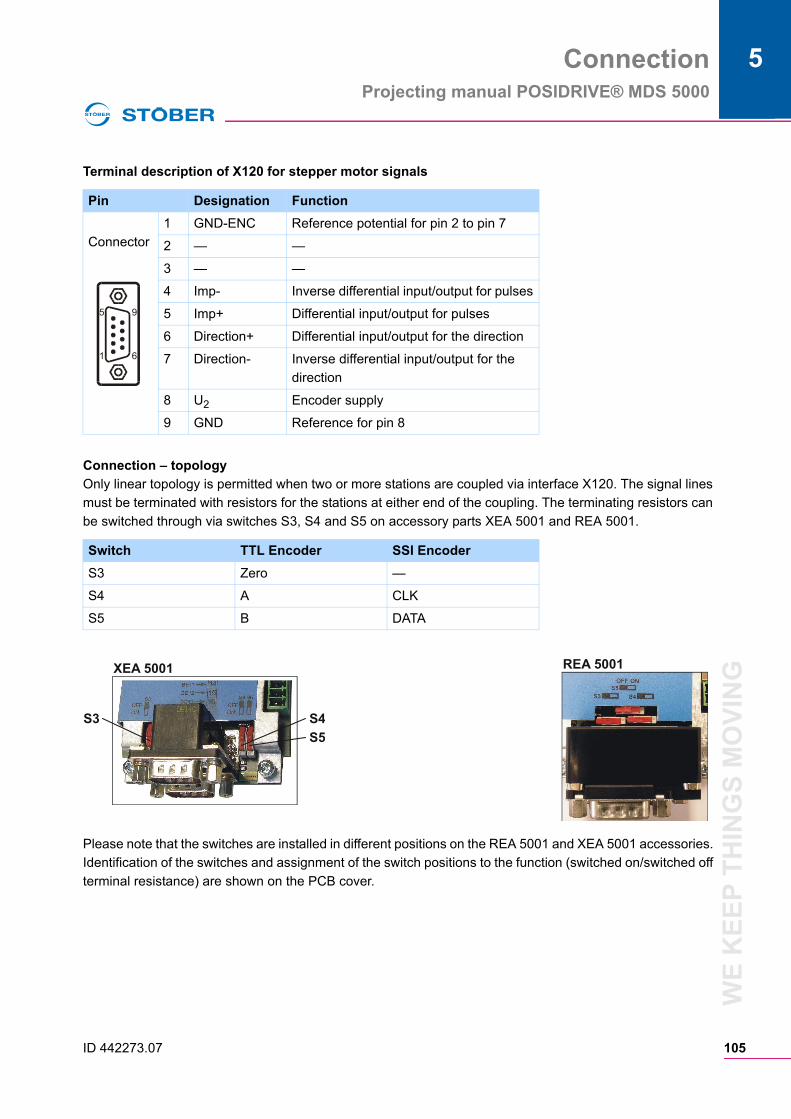
ConnectionProjecting manual POSIDRIVE® MDS 5000
WE
KE
EP
TH
ING
S M
OV
ING
5
Terminal description of X120 for stepper motor signals
Connection – topology
Only linear topology is permitted when two or more stations are coupled via interface X120. The signal lines
must be terminated with resistors for the stations at either end of the coupling. The terminating resistors can
be switched through via switches S3, S4 and S5 on accessory parts XEA 5001 and REA 5001.
Please note that the switches are installed in different positions on the REA 5001 and XEA 5001 accessories.
Identification of the switches and assignment of the switch positions to the function (switched on/switched off
terminal resistance) are shown on the PCB cover.
Pin Designation Function
Connector
1 GND-ENC Reference potential for pin 2 to pin 7
2 — —
3 — —
4 Imp- Inverse differential input/output for pulses
5 Imp+ Differential input/output for pulses
6 Direction+ Differential input/output for the direction
7 Direction- Inverse differential input/output for the
direction
8 U2 Encoder supply
9 GND Reference for pin 8
Switch TTL Encoder SSI Encoder
S3 Zero —
S4 A CLK
S5 B DATA
5
1
9
6
REA 5001
S3
XEA 5001
S5
S4
ID 442273.07 105
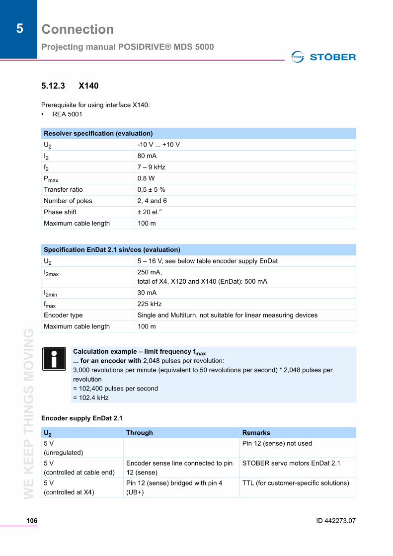
Connection
106
Projecting manual POSIDRIVE® MDS 5000
5W
E K
EE
P T
HIN
GS
MO
VIN
G
5.12.3 X140
Prerequisite for using interface X140:
• REA 5001
Encoder supply EnDat 2.1
Resolver specification (evaluation)
U2 -10 V ... +10 V
I2 80 mA
f2 7 – 9 kHz
Pmax 0.8 W
Transfer ratio 0,5 ± 5 %
Number of poles 2, 4 and 6
Phase shift ± 20 el.°
Maximum cable length 100 m
Specification EnDat 2.1 sin/cos (evaluation)
U2 5 – 16 V, see below table encoder supply EnDat
I2max 250 mA, total of X4, X120 and X140 (EnDat): 500 mA
I2min 30 mA
fmax 225 kHz
Encoder type Single and Multiturn, not suitable for linear measuring devices
Maximum cable length 100 m
Calculation example – limit frequency fmax ... for an encoder with 2,048 pulses per revolution: 3,000 revolutions per minute (equivalent to 50 revolutions per second) * 2,048 pulses per
revolution= 102,400 pulses per second = 102.4 kHz
U2 Through Remarks
5 V (unregulated)
Pin 12 (sense) not used
5 V (controlled at cable end)
Encoder sense line connected to pin
12 (sense)
STOBER servo motors EnDat 2.1
5 V(controlled at X4)
Pin 12 (sense) bridged with pin 4
(UB+)
TTL (for customer-specific solutions)
ID 442273.07
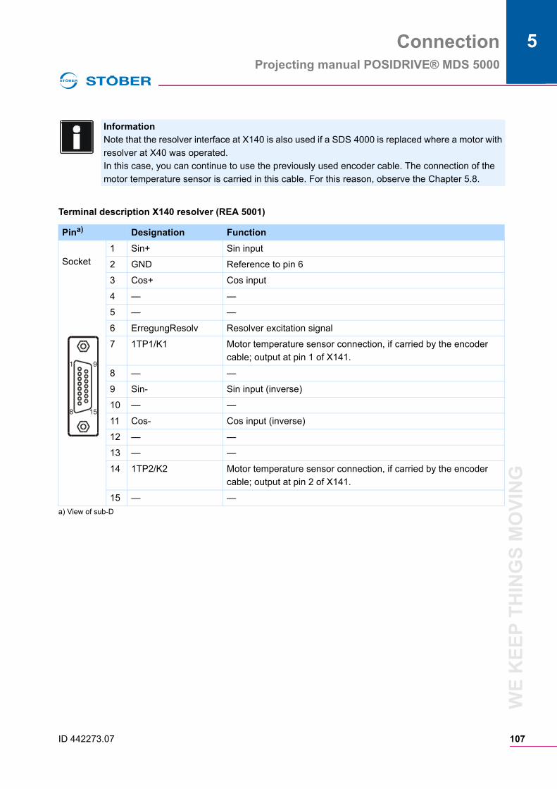
ConnectionProjecting manual POSIDRIVE® MDS 5000
WE
KE
EP
TH
ING
S M
OV
ING
5
Terminal description X140 resolver (REA 5001)
Information
Note that the resolver interface at X140 is also used if a SDS 4000 is replaced where a motor with
resolver at X40 was operated.
In this case, you can continue to use the previously used encoder cable. The connection of the
motor temperature sensor is carried in this cable. For this reason, observe the Chapter 5.8.
Pina)
a) View of sub-D
Designation Function
Socket
1 Sin+ Sin input
2 GND Reference to pin 6
3 Cos+ Cos input
4 — —
5 — —
6 ErregungResolv Resolver excitation signal
7 1TP1/K1 Motor temperature sensor connection, if carried by the encoder
cable; output at pin 1 of X141.
8 — —
9 Sin- Sin input (inverse)
10 — —
11 Cos- Cos input (inverse)
12 — —
13 — —
14 1TP2/K2 Motor temperature sensor connection, if carried by the encoder
cable; output at pin 2 of X141.
15 — —
9
15
1
8
ID 442273.07 107
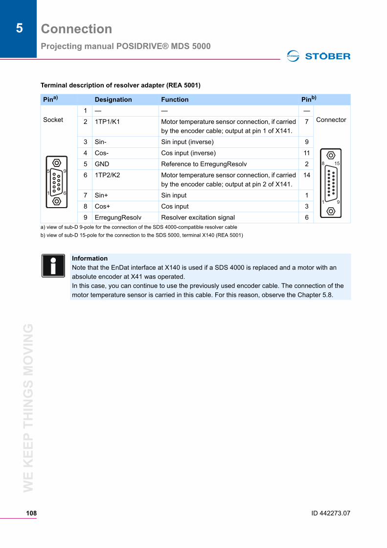
Connection
108
Projecting manual POSIDRIVE® MDS 5000
5W
E K
EE
P T
HIN
GS
MO
VIN
G
Terminal description of resolver adapter (REA 5001)
Pina)
a) view of sub-D 9-pole for the connection of the SDS 4000-compatible resolver cable
Designation Function Pinb)
b) view of sub-D 15-pole for the connection to the SDS 5000, terminal X140 (REA 5001)
Socket
1 — — —
Connector2 1TP1/K1 Motor temperature sensor connection, if carried
by the encoder cable; output at pin 1 of X141.
7
3 Sin- Sin input (inverse) 9
4 Cos- Cos input (inverse) 11
5 GND Reference to ErregungResolv 2
6 1TP2/K2 Motor temperature sensor connection, if carried
by the encoder cable; output at pin 2 of X141.
14
7 Sin+ Sin input 1
8 Cos+ Cos input 3
9 ErregungResolv Resolver excitation signal 6
15
9
8
1
Information
Note that the EnDat interface at X140 is used if a SDS 4000 is replaced and a motor with an
absolute encoder at X41 was operated.
In this case, you can continue to use the previously used encoder cable. The connection of the
motor temperature sensor is carried in this cable. For this reason, observe the Chapter 5.8.
ID 442273.07
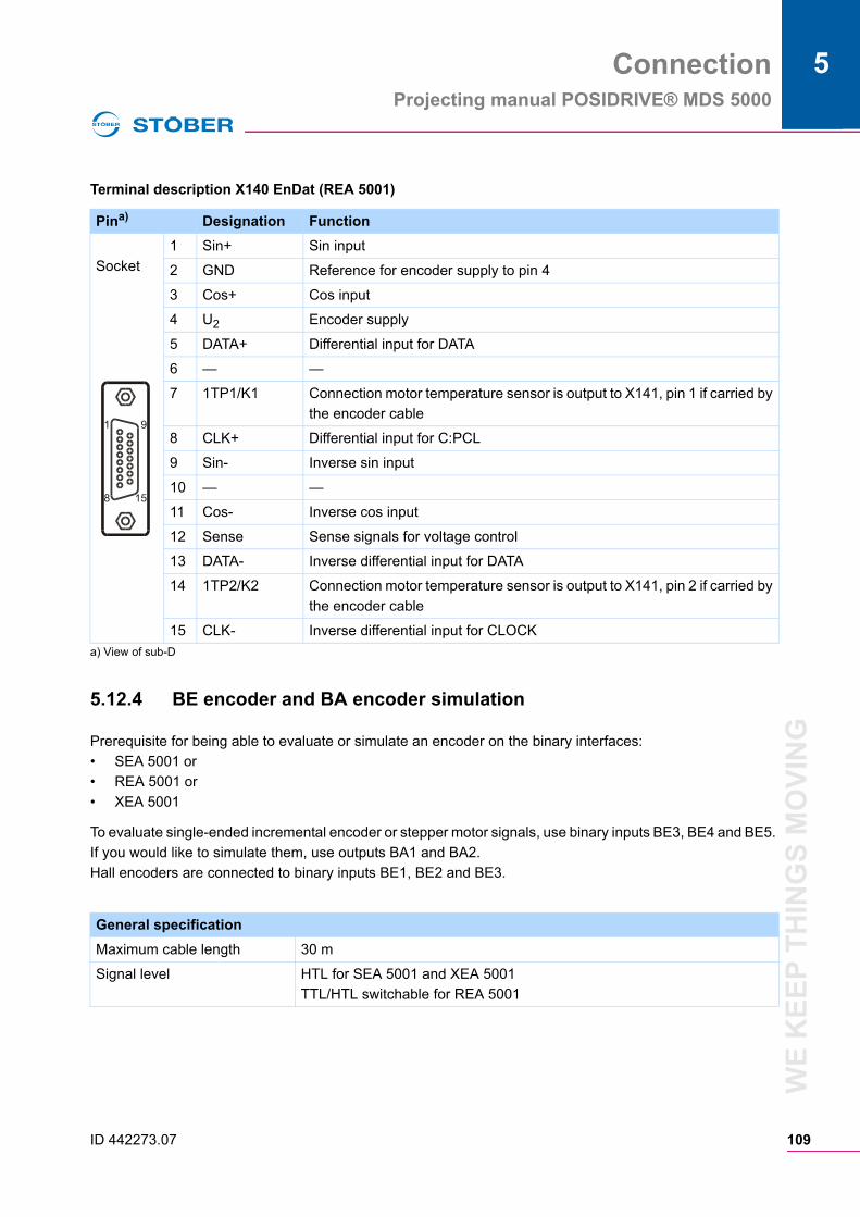
ConnectionProjecting manual POSIDRIVE® MDS 5000
WE
KE
EP
TH
ING
S M
OV
ING
5
Terminal description X140 EnDat (REA 5001)
5.12.4 BE encoder and BA encoder simulation
Prerequisite for being able to evaluate or simulate an encoder on the binary interfaces:
• SEA 5001 or
• REA 5001 or
• XEA 5001
To evaluate single-ended incremental encoder or stepper motor signals, use binary inputs BE3, BE4 and BE5.
If you would like to simulate them, use outputs BA1 and BA2.
Hall encoders are connected to binary inputs BE1, BE2 and BE3.
Pina)
a) View of sub-D
Designation Function
Socket
1 Sin+ Sin input
2 GND Reference for encoder supply to pin 4
3 Cos+ Cos input
4 U2 Encoder supply
5 DATA+ Differential input for DATA
6 — —
7 1TP1/K1 Connection motor temperature sensor is output to X141, pin 1 if carried by
the encoder cable
8 CLK+ Differential input for C:PCL
9 Sin- Inverse sin input
10 — —
11 Cos- Inverse cos input
12 Sense Sense signals for voltage control
13 DATA- Inverse differential input for DATA
14 1TP2/K2 Connection motor temperature sensor is output to X141, pin 2 if carried by
the encoder cable
15 CLK- Inverse differential input for CLOCK
General specification
Maximum cable length 30 m
Signal level HTL for SEA 5001 and XEA 5001
TTL/HTL switchable for REA 5001
9
15
1
8
ID 442273.07 109
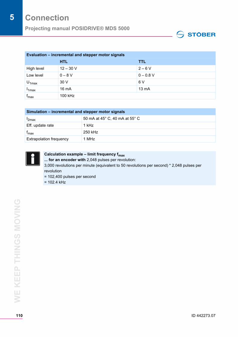
Connection
110
Projecting manual POSIDRIVE® MDS 5000
5W
E K
EE
P T
HIN
GS
MO
VIN
G
Evaluation – incremental and stepper motor signals
HTL TTL
High level 12 – 30 V 2 – 6 V
Low level 0 – 8 V 0 – 0.8 V
U1max 30 V 6 V
I1max 16 mA 13 mA
fmax 100 kHz
Simulation – incremental and stepper motor signals
I2max 50 mA at 45° C, 40 mA at 55° C
Eff. update rate 1 kHz
fmax 250 kHz
Extrapolation frequency 1 MHz
Calculation example – limit frequency fmax ... for an encoder with 2,048 pulses per revolution: 3,000 revolutions per minute (equivalent to 50 revolutions per second) * 2,048 pulses per
revolution= 102,400 pulses per second = 102.4 kHz
ID 442273.07
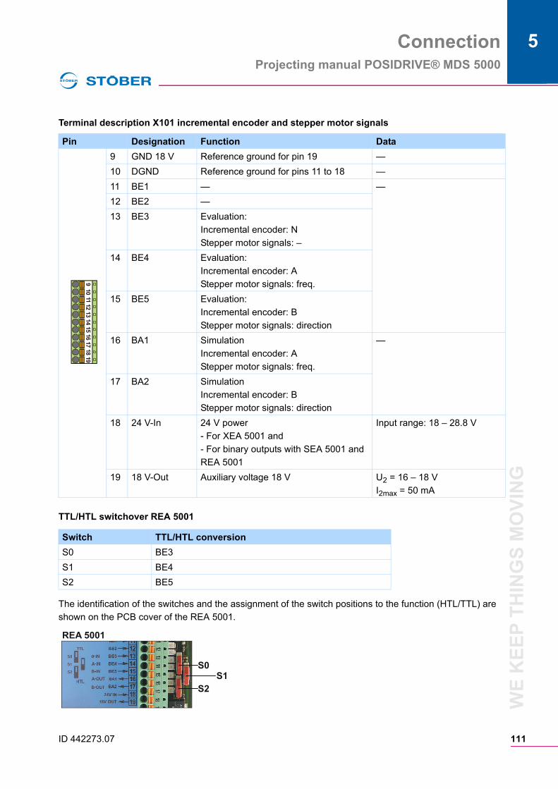
ConnectionProjecting manual POSIDRIVE® MDS 5000
WE
KE
EP
TH
ING
S M
OV
ING
5
Terminal description X101 incremental encoder and stepper motor signals
TTL/HTL switchover REA 5001
The identification of the switches and the assignment of the switch positions to the function (HTL/TTL) are
shown on the PCB cover of the REA 5001.
Pin Designation Function Data
9 GND 18 V Reference ground for pin 19 —
10 DGND Reference ground for pins 11 to 18 —
11 BE1 — —
12 BE2 —
13 BE3 Evaluation:
Incremental encoder: N
Stepper motor signals: –
14 BE4 Evaluation:
Incremental encoder: A
Stepper motor signals: freq.
15 BE5 Evaluation:
Incremental encoder: B
Stepper motor signals: direction
16 BA1 Simulation
Incremental encoder: A
Stepper motor signals: freq.
—
17 BA2 Simulation
Incremental encoder: B
Stepper motor signals: direction
18 24 V-In 24 V power
- For XEA 5001 and
- For binary outputs with SEA 5001 and
REA 5001
Input range: 18 – 28.8 V
19 18 V-Out Auxiliary voltage 18 V U2 = 16 – 18 V
I2max = 50 mA
Switch TTL/HTL conversion
S0 BE3
S1 BE4
S2 BE5
910
1112
1314
1516
1718
19
REA 5001
S0S1
S2
ID 442273.07 111
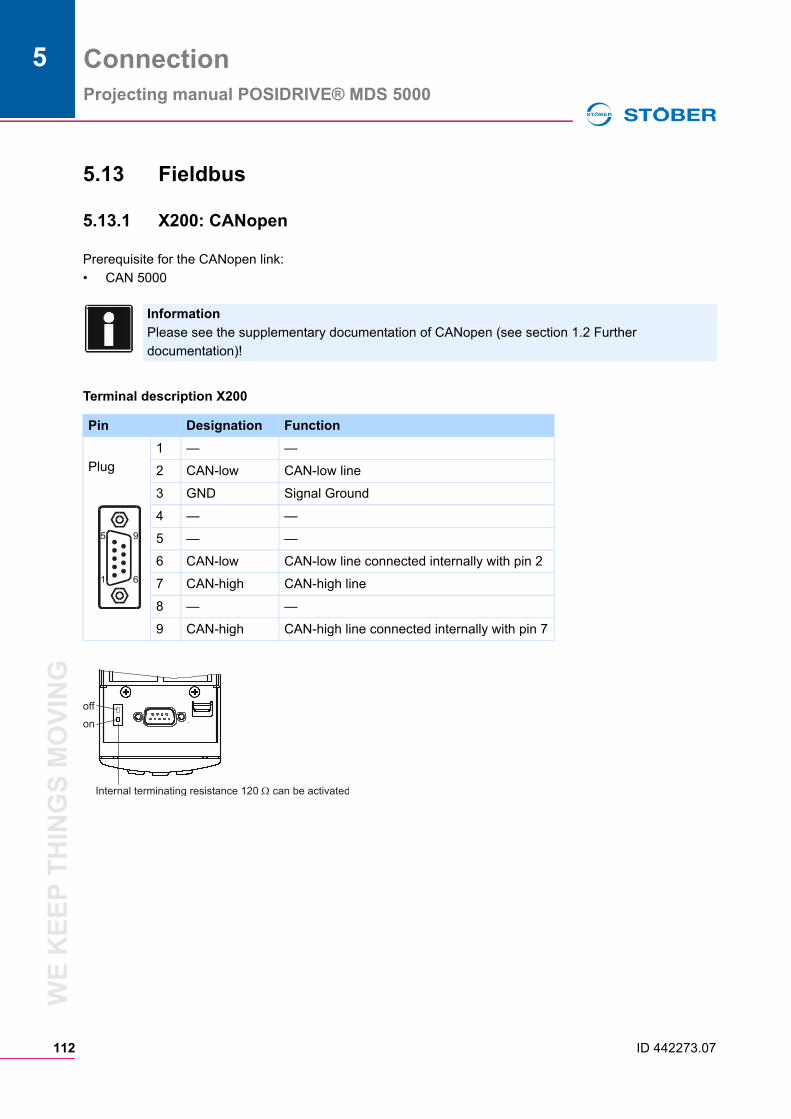
Connection
112
Projecting manual POSIDRIVE® MDS 5000
5W
E K
EE
P T
HIN
GS
MO
VIN
G
5.13 Fieldbus
5.13.1 X200: CANopen
Prerequisite for the CANopen link:
• CAN 5000
Terminal description X200
Information
Please see the supplementary documentation of CANopen (see section 1.2 Further
documentation)!
Pin Designation Function
Plug
1 — —
2 CAN-low CAN-low line
3 GND Signal Ground
4 — —
5 — —
6 CAN-low CAN-low line connected internally with pin 2
7 CAN-high CAN-high line
8 — —
9 CAN-high CAN-high line connected internally with pin 7
5
1
9
6
off
on
Internal terminating resistance 120 can be activated
ID 442273.07
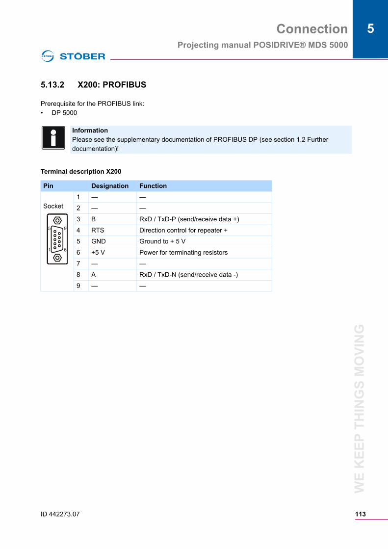
ConnectionProjecting manual POSIDRIVE® MDS 5000
WE
KE
EP
TH
ING
S M
OV
ING
5
5.13.2 X200: PROFIBUS
Prerequisite for the PROFIBUS link:
• DP 5000
Terminal description X200
Information
Please see the supplementary documentation of PROFIBUS DP (see section 1.2 Further
documentation)!
Pin Designation Function
Socket
1 — —
2 — —
3 B RxD / TxD-P (send/receive data +)
4 RTS Direction control for repeater +
5 GND Ground to + 5 V
6 +5 V Power for terminating resistors
7 — —
8 A RxD / TxD-N (send/receive data -)
9 — —
ID 442273.07 113
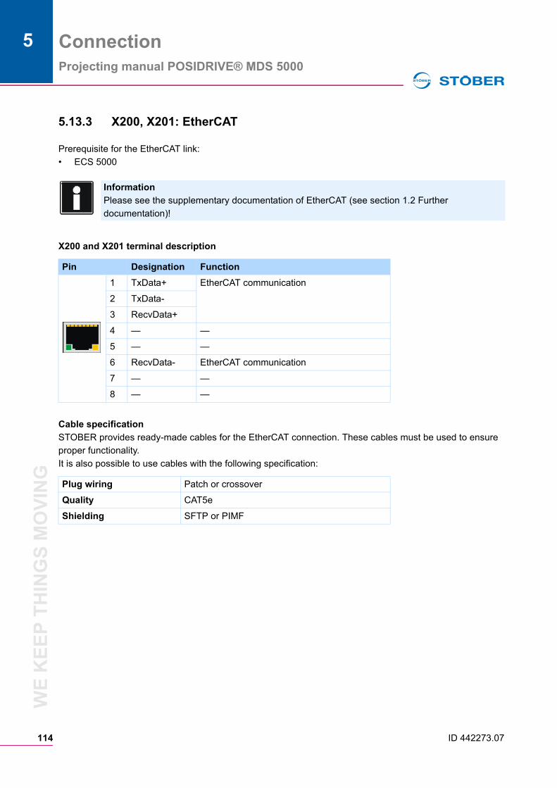
Connection
114
Projecting manual POSIDRIVE® MDS 5000
5W
E K
EE
P T
HIN
GS
MO
VIN
G
5.13.3 X200, X201: EtherCAT
Prerequisite for the EtherCAT link:
• ECS 5000
X200 and X201 terminal description
Cable specification
STOBER provides ready-made cables for the EtherCAT connection. These cables must be used to ensure
proper functionality.
It is also possible to use cables with the following specification:
Information
Please see the supplementary documentation of EtherCAT (see section 1.2 Further
documentation)!
Pin Designation Function
1 TxData+ EtherCAT communication
2 TxData-
3 RecvData+
4 — —
5 — —
6 RecvData- EtherCAT communication
7 — —
8 — —
Plug wiring Patch or crossover
Quality CAT5e
Shielding SFTP or PIMF
ID 442273.07

ConnectionProjecting manual POSIDRIVE® MDS 5000
WE
KE
EP
TH
ING
S M
OV
ING
5
5.13.4 X200, X201: PROFINET
Requirement for the die PROFINET connection:
• PN 5000
X200 and X201 terminal description
The terminal configuration is determined by T 568-B.
Observe the PROFINET installation guideline for the cable specification (PROFINET Order No. 8.071,
identification: TC2-08-0001); you can obtain the document at www. profibus.com.
Information
Observe the PROFINET operating manual (see section 1.2 Further documentation)!
Pin Designation Function
1 TxData + PROFINET communication
2 TxData -
3 RecvData +
4 — Connect via RC-link with housing
5 —
6 RecvData - PROFINET communication
7 — Connect via RC-link with housing
8 —
ID 442273.07 115
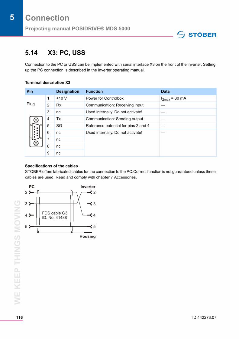
Connection
116
Projecting manual POSIDRIVE® MDS 5000
5W
E K
EE
P T
HIN
GS
MO
VIN
G
5.14 X3: PC, USS
Connection to the PC or USS can be implemented with serial interface X3 on the front of the inverter. Setting
up the PC connection is described in the inverter operating manual.
Terminal description X3
Specifications of the cables
STOBER offers fabricated cables for the connection to the PC.Correct function is not guaranteed unless these
cables are used. Read and comply with chapter 7 Accessories.
Pin Designation Function Data
Plug
1 +10 V Power for Controlbox I2max = 30 mA
2 Rx Communication: Receiving input —
3 nc Used internally. Do not activate! —
4 Tx Communication: Sending output —
5 SG Reference potential for pins 2 and 4 —
6 nc Used internally. Do not activate! —
7 nc
8 nc
9 nc
5
1
9
6
2 2
3 3
4 4
5 5
Housing
InverterPC
FDS cable G3ID. No. 41488
ID 442273.07
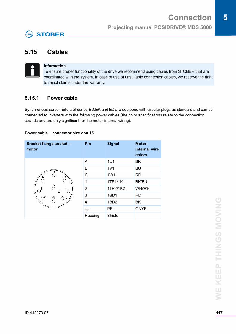
ConnectionProjecting manual POSIDRIVE® MDS 5000
WE
KE
EP
TH
ING
S M
OV
ING
5
5.15 Cables
5.15.1 Power cable
Synchronous servo motors of series ED/EK and EZ are equipped with circular plugs as standard and can be
connected to inverters with the following power cables (the color specifications relate to the connection
strands and are only significant for the motor-internal wiring).
Information
To ensure proper functionality of the drive we recommend using cables from STOBER that are
coordinated with the system. In case of use of unsuitable connection cables, we reserve the right
to reject claims under the warranty.
Power cable – connector size con.15
Bracket flange socket –
motor
Pin Signal Motor-
internal wire
colors
A 1U1 BK
B 1V1 BU
C 1W1 RD
1 1TP1/1K1 BK/BN
2 1TP2/1K2 WH/WH
3 1BD1 RD
4 1BD2 BK
PE GNYE
Housing Shield
ID 442273.07 117
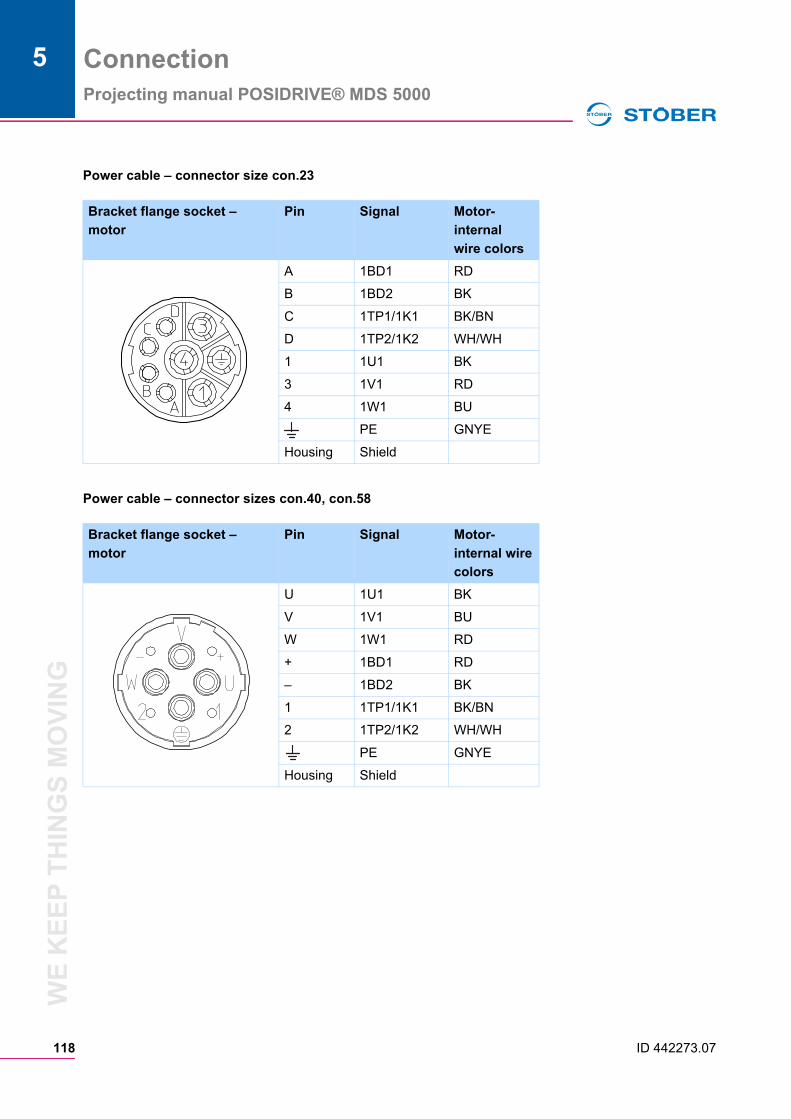
Connection
118
Projecting manual POSIDRIVE® MDS 5000
5W
E K
EE
P T
HIN
GS
MO
VIN
G
Power cable – connector size con.23
Bracket flange socket –
motor
Pin Signal Motor-
internalwire colors
A 1BD1 RD
B 1BD2 BK
C 1TP1/1K1 BK/BN
D 1TP2/1K2 WH/WH
1 1U1 BK
3 1V1 RD
4 1W1 BU
PE GNYE
Housing Shield
Power cable – connector sizes con.40, con.58
Bracket flange socket –
motor
Pin Signal Motor-
internal wire
colors
U 1U1 BK
V 1V1 BU
W 1W1 RD
+ 1BD1 RD
– 1BD2 BK
1 1TP1/1K1 BK/BN
2 1TP2/1K2 WH/WH
PE GNYE
Housing Shield
ID 442273.07
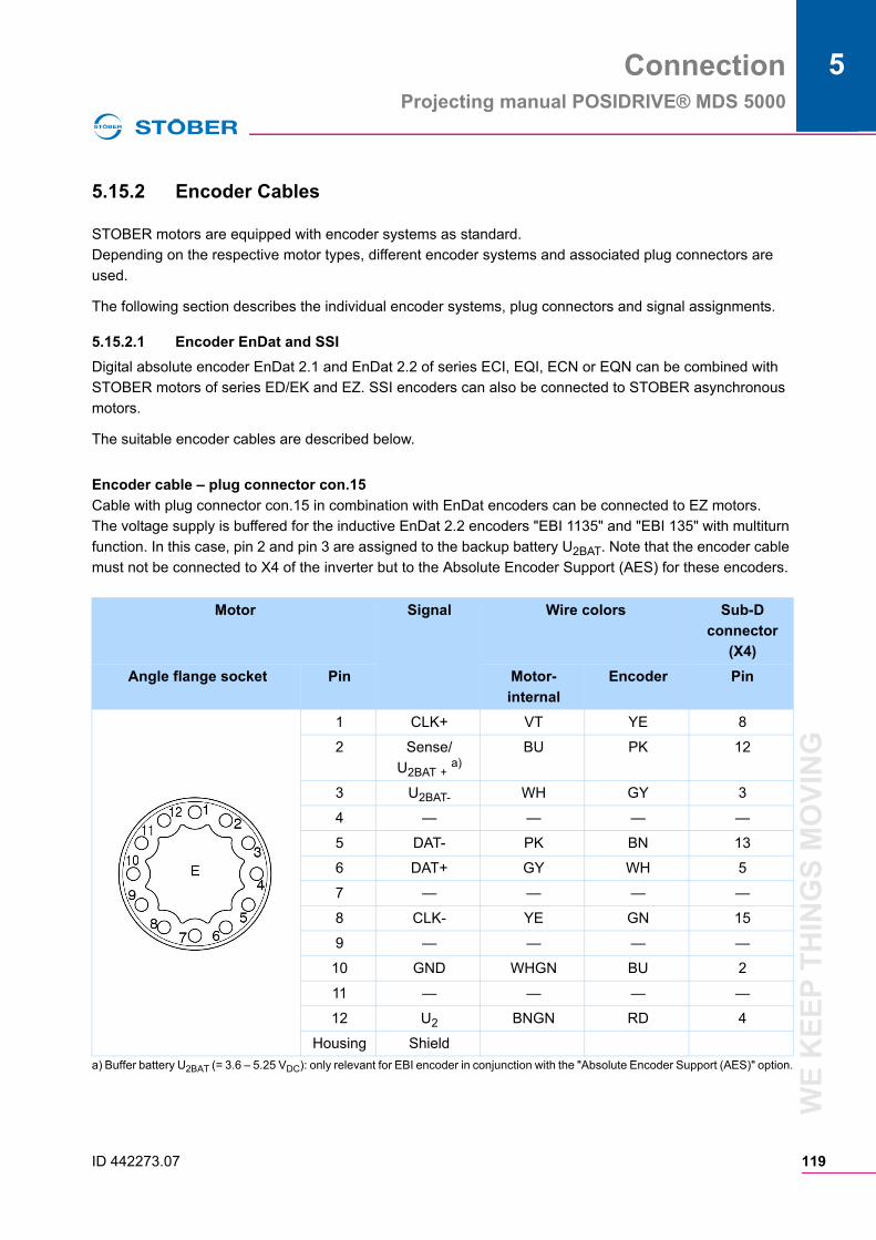
ConnectionProjecting manual POSIDRIVE® MDS 5000
WE
KE
EP
TH
ING
S M
OV
ING
5
5.15.2 Encoder Cables
STOBER motors are equipped with encoder systems as standard.
Depending on the respective motor types, different encoder systems and associated plug connectors are
used.
The following section describes the individual encoder systems, plug connectors and signal assignments.
5.15.2.1 Encoder EnDat and SSI
Digital absolute encoder EnDat 2.1 and EnDat 2.2 of series ECI, EQI, ECN or EQN can be combined with
STOBER motors of series ED/EK and EZ. SSI encoders can also be connected to STOBER asynchronous
motors.
The suitable encoder cables are described below.
Encoder cable – plug connector con.15
Cable with plug connector con.15 in combination with EnDat encoders can be connected to EZ motors.
The voltage supply is buffered for the inductive EnDat 2.2 encoders "EBI 1135" and "EBI 135" with multiturn
function. In this case, pin 2 and pin 3 are assigned to the backup battery U2BAT. Note that the encoder cable
must not be connected to X4 of the inverter but to the Absolute Encoder Support (AES) for these encoders.
Motor Signal Wire colors Sub-D
connector
(X4)
Angle flange socket Pin Motor-
internal
Encoder Pin
1 CLK+ VT YE 8
2 Sense/
U2BAT + a)
a) Buffer battery U2BAT (= 3.6 – 5.25 VDC): only relevant for EBI encoder in conjunction with the "Absolute Encoder Support (AES)" option.
BU PK 12
3 U2BAT- WH GY 3
4 — — — —
5 DAT- PK BN 13
6 DAT+ GY WH 5
7 — — — —
8 CLK- YE GN 15
9 — — — —
10 GND WHGN BU 2
11 — — — —
12 U2 BNGN RD 4
Housing Shield
ID 442273.07 119
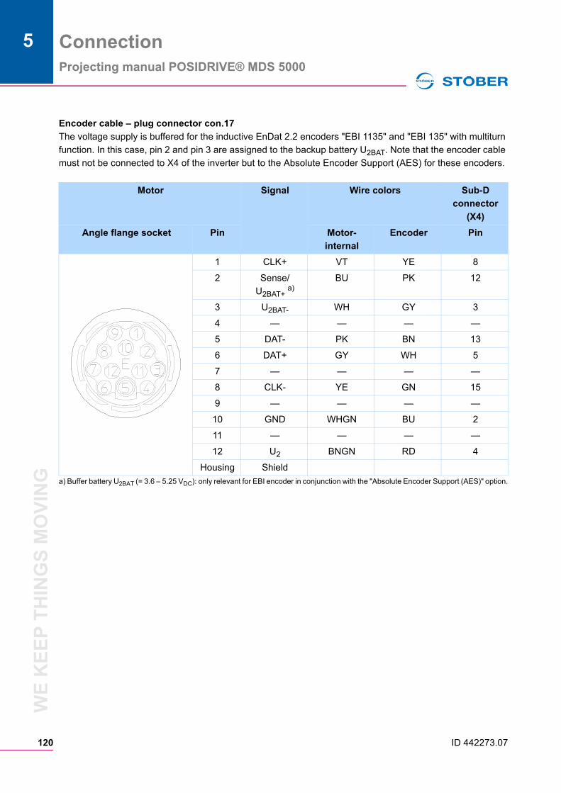
Connection
120
Projecting manual POSIDRIVE® MDS 5000
5W
E K
EE
P T
HIN
GS
MO
VIN
G
Encoder cable – plug connector con.17
The voltage supply is buffered for the inductive EnDat 2.2 encoders "EBI 1135" and "EBI 135" with multiturn
function. In this case, pin 2 and pin 3 are assigned to the backup battery U2BAT. Note that the encoder cable
must not be connected to X4 of the inverter but to the Absolute Encoder Support (AES) for these encoders.
Motor Signal Wire colors Sub-D
connector
(X4)
Angle flange socket Pin Motor-
internal
Encoder Pin
1 CLK+ VT YE 8
2 Sense/
U2BAT+ a)
a) Buffer battery U2BAT (= 3.6 – 5.25 VDC): only relevant for EBI encoder in conjunction with the "Absolute Encoder Support (AES)" option.
BU PK 12
3 U2BAT- WH GY 3
4 — — — —
5 DAT- PK BN 13
6 DAT+ GY WH 5
7 — — — —
8 CLK- YE GN 15
9 — — — —
10 GND WHGN BU 2
11 — — — —
12 U2 BNGN RD 4
Housing Shield
ID 442273.07
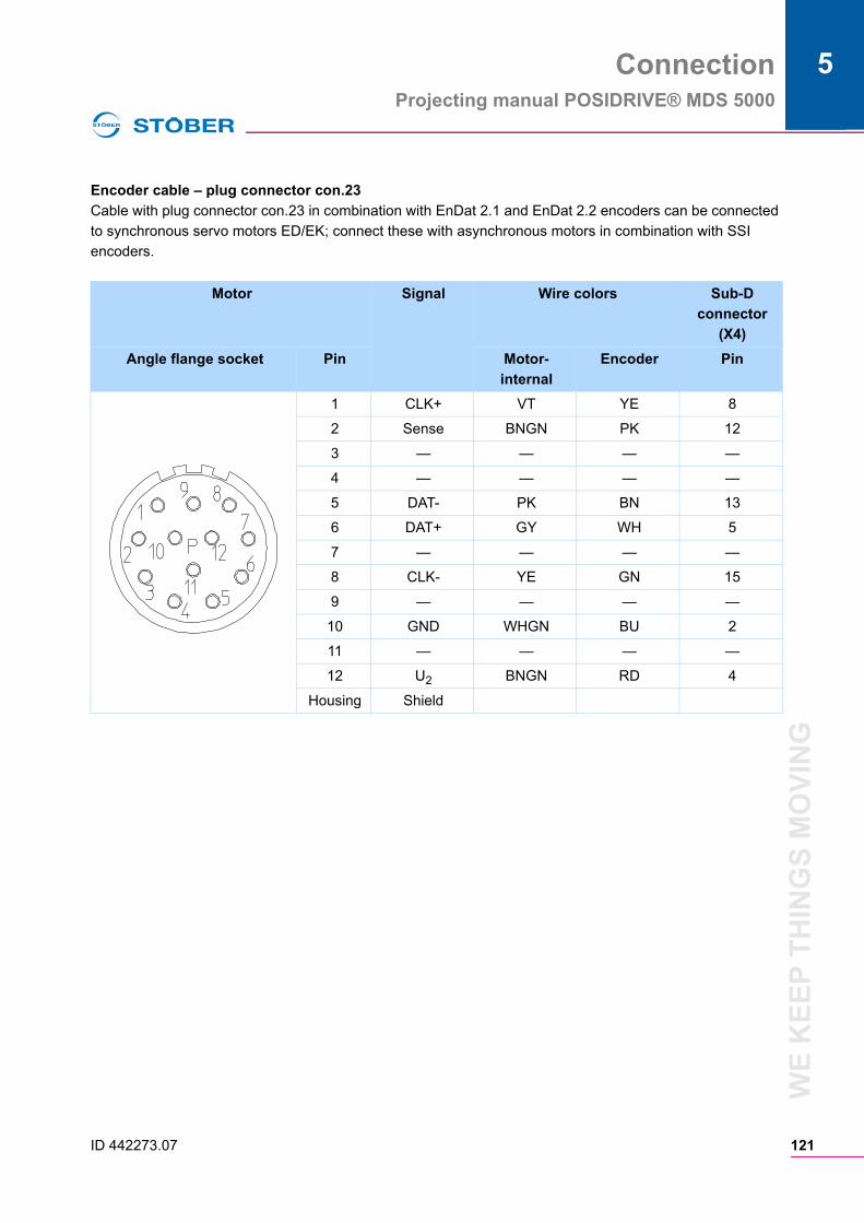
ConnectionProjecting manual POSIDRIVE® MDS 5000
WE
KE
EP
TH
ING
S M
OV
ING
5
Encoder cable – plug connector con.23
Cable with plug connector con.23 in combination with EnDat 2.1 and EnDat 2.2 encoders can be connected
to synchronous servo motors ED/EK; connect these with asynchronous motors in combination with SSI
encoders.
Motor Signal Wire colors Sub-D
connector
(X4)
Angle flange socket Pin Motor-
internal
Encoder Pin
1 CLK+ VT YE 8
2 Sense BNGN PK 12
3 — — — —
4 — — — —
5 DAT- PK BN 13
6 DAT+ GY WH 5
7 — — — —
8 CLK- YE GN 15
9 — — — —
10 GND WHGN BU 2
11 — — — —
12 U2 BNGN RD 4
Housing Shield
ID 442273.07 121
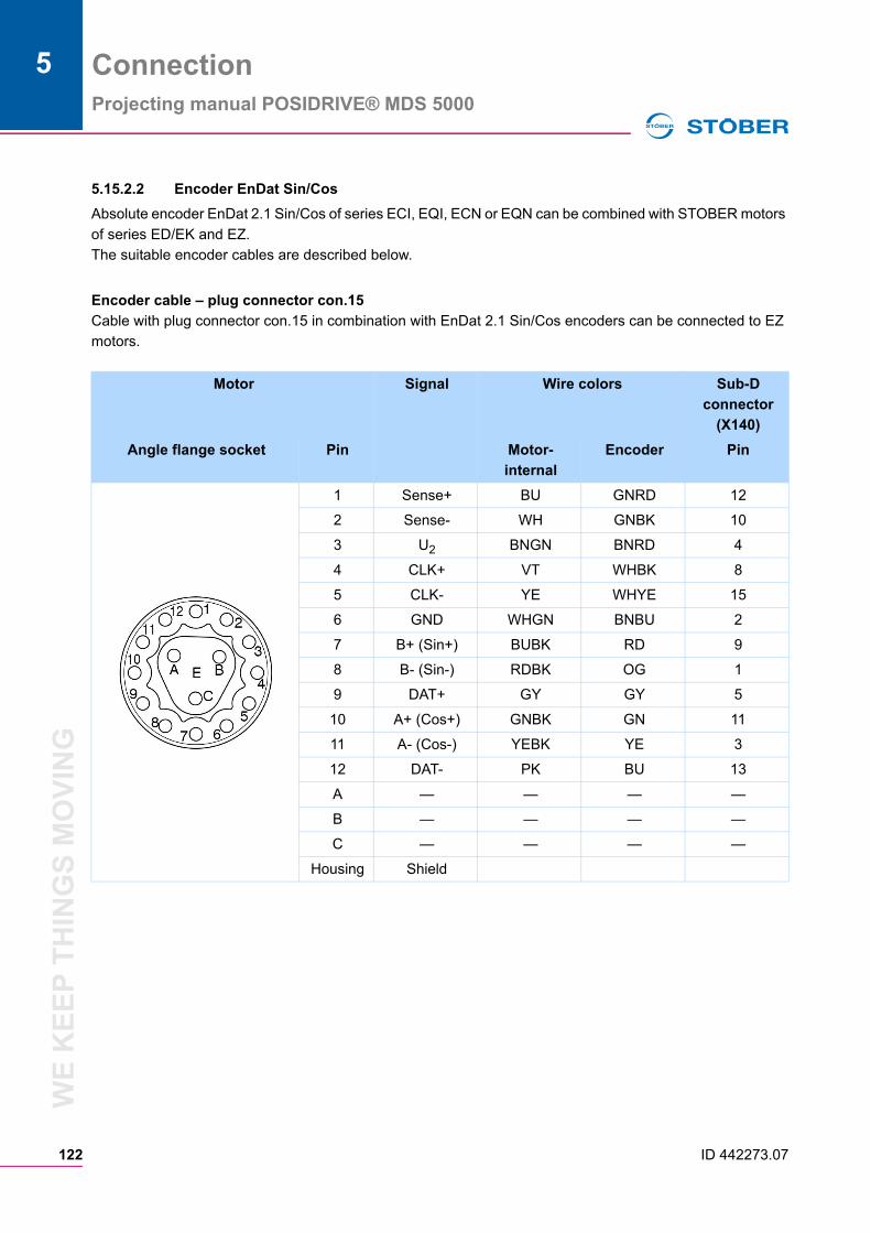
Connection
122
Projecting manual POSIDRIVE® MDS 5000
5W
E K
EE
P T
HIN
GS
MO
VIN
G
5.15.2.2 Encoder EnDat Sin/Cos
Absolute encoder EnDat 2.1 Sin/Cos of series ECI, EQI, ECN or EQN can be combined with STOBER motors
of series ED/EK and EZ.
The suitable encoder cables are described below.
Encoder cable – plug connector con.15
Cable with plug connector con.15 in combination with EnDat 2.1 Sin/Cos encoders can be connected to EZ
motors.
Motor Signal Wire colors Sub-D
connector
(X140)
Angle flange socket Pin Motor-
internal
Encoder Pin
1 Sense+ BU GNRD 12
2 Sense- WH GNBK 10
3 U2 BNGN BNRD 4
4 CLK+ VT WHBK 8
5 CLK- YE WHYE 15
6 GND WHGN BNBU 2
7 B+ (Sin+) BUBK RD 9
8 B- (Sin-) RDBK OG 1
9 DAT+ GY GY 5
10 A+ (Cos+) GNBK GN 11
11 A- (Cos-) YEBK YE 3
12 DAT- PK BU 13
A — — — —
B — — — —
C — — — —
Housing Shield
ID 442273.07
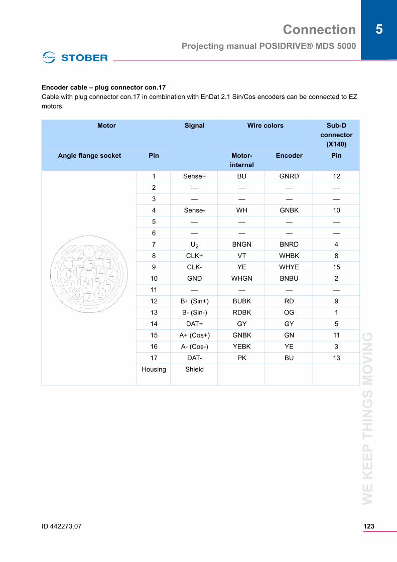
ConnectionProjecting manual POSIDRIVE® MDS 5000
WE
KE
EP
TH
ING
S M
OV
ING
5
Encoder cable – plug connector con.17
Cable with plug connector con.17 in combination with EnDat 2.1 Sin/Cos encoders can be connected to EZ
motors.
Motor Signal Wire colors Sub-D
connector
(X140)
Angle flange socket Pin Motor-
internal
Encoder Pin
1 Sense+ BU GNRD 12
2 — — — —
3 — — — —
4 Sense- WH GNBK 10
5 — — — —
6 — — — —
7 U2 BNGN BNRD 4
8 CLK+ VT WHBK 8
9 CLK- YE WHYE 15
10 GND WHGN BNBU 2
11 — — — —
12 B+ (Sin+) BUBK RD 9
13 B- (Sin-) RDBK OG 1
14 DAT+ GY GY 5
15 A+ (Cos+) GNBK GN 11
16 A- (Cos-) YEBK YE 3
17 DAT- PK BU 13
Housing Shield
ID 442273.07 123
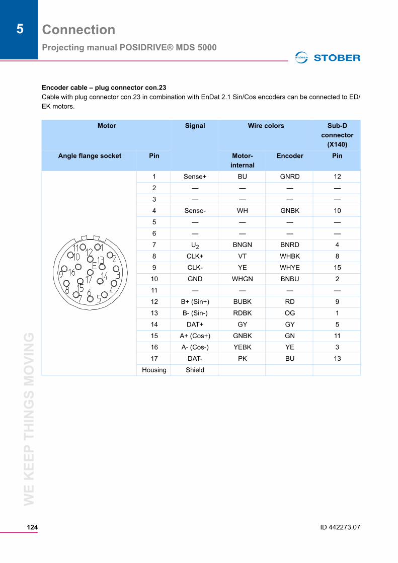
Connection
124
Projecting manual POSIDRIVE® MDS 5000
5W
E K
EE
P T
HIN
GS
MO
VIN
G
Encoder cable – plug connector con.23
Cable with plug connector con.23 in combination with EnDat 2.1 Sin/Cos encoders can be connected to ED/
EK motors.
Motor Signal Wire colors Sub-D
connector
(X140)
Angle flange socket Pin Motor-
internal
Encoder Pin
1 Sense+ BU GNRD 12
2 — — — —
3 — — — —
4 Sense- WH GNBK 10
5 — — — —
6 — — — —
7 U2 BNGN BNRD 4
8 CLK+ VT WHBK 8
9 CLK- YE WHYE 15
10 GND WHGN BNBU 2
11 — — — —
12 B+ (Sin+) BUBK RD 9
13 B- (Sin-) RDBK OG 1
14 DAT+ GY GY 5
15 A+ (Cos+) GNBK GN 11
16 A- (Cos-) YEBK YE 3
17 DAT- PK BU 13
Housing Shield
ID 442273.07
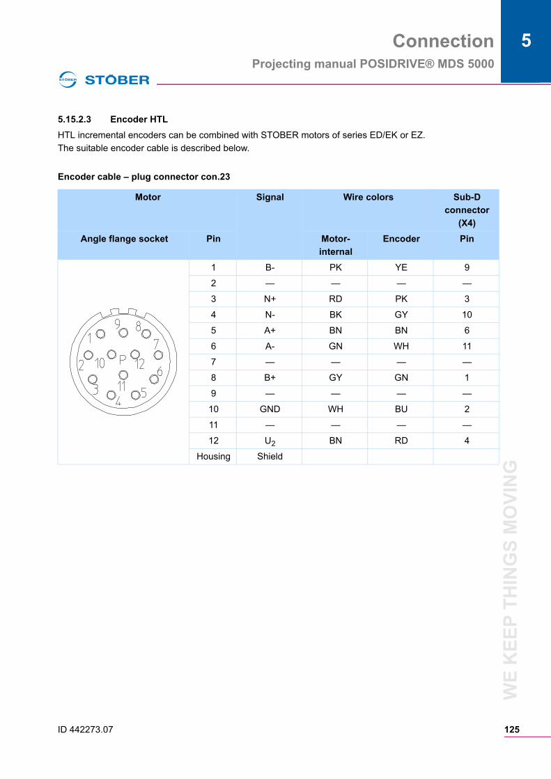
ConnectionProjecting manual POSIDRIVE® MDS 5000
WE
KE
EP
TH
ING
S M
OV
ING
5
5.15.2.3 Encoder HTL
HTL incremental encoders can be combined with STOBER motors of series ED/EK or EZ.
The suitable encoder cable is described below.
Encoder cable – plug connector con.23
Motor Signal Wire colors Sub-D
connector
(X4)
Angle flange socket Pin Motor-
internal
Encoder Pin
1 B- PK YE 9
2 — — — —
3 N+ RD PK 3
4 N- BK GY 10
5 A+ BN BN 6
6 A- GN WH 11
7 — — — —
8 B+ GY GN 1
9 — — — —
10 GND WH BU 2
11 — — — —
12 U2 BN RD 4
Housing Shield
ID 442273.07 125
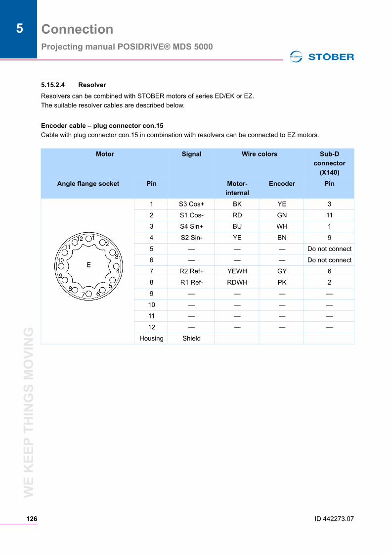
Connection
126
Projecting manual POSIDRIVE® MDS 5000
5W
E K
EE
P T
HIN
GS
MO
VIN
G
5.15.2.4 Resolver
Resolvers can be combined with STOBER motors of series ED/EK or EZ.
The suitable resolver cables are described below.
Encoder cable – plug connector con.15
Cable with plug connector con.15 in combination with resolvers can be connected to EZ motors.
Motor Signal Wire colors Sub-D
connector
(X140)
Angle flange socket Pin Motor-
internal
Encoder Pin
1 S3 Cos+ BK YE 3
2 S1 Cos- RD GN 11
3 S4 Sin+ BU WH 1
4 S2 Sin- YE BN 9
5 — — — Do not connect
6 — — — Do not connect
7 R2 Ref+ YEWH GY 6
8 R1 Ref- RDWH PK 2
9 — — — —
10 — — — —
11 — — — —
12 — — — —
Housing Shield
ID 442273.07

ConnectionProjecting manual POSIDRIVE® MDS 5000
WE
KE
EP
TH
ING
S M
OV
ING
5
Encoder cable – plug connector con.17
Cable with plug connector con.17 in combination with resolvers can be connected to EZ motors.
Motor Signal Wire colors Sub-D
connector at
terminal X140
Angle flange socket Pin Motor-
internal
Encoder Pin
1 S3 Cos+ BK YE 3
2 S1 Cos- RD GN 11
3 S4 Sin+ BU WH 1
4 S2 Sin- YE BN 9
5 — — — Do not connect
6 — — — Do not connect
7 R2 Ref+ YEWH GY 6
8 R1 Ref- RDWH PK 2
9 — — — —
10 — — — —
11 — — — —
12 — — — —
Housing Shield
ID 442273.07 127
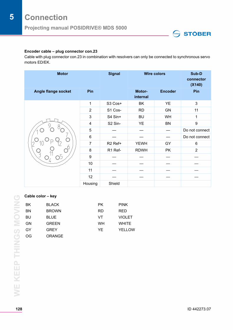
Connection
128
Projecting manual POSIDRIVE® MDS 5000
5W
E K
EE
P T
HIN
GS
MO
VIN
G
Encoder cable – plug connector con.23
Cable with plug connector con.23 in combination with resolvers can only be connected to synchronous servo
motors ED/EK.
Cable color – key
Motor Signal Wire colors Sub-D
connector
(X140)
Angle flange socket Pin Motor-
internal
Encoder Pin
1 S3 Cos+ BK YE 3
2 S1 Cos- RD GN 11
3 S4 Sin+ BU WH 1
4 S2 Sin- YE BN 9
5 — — — Do not connect
6 — — — Do not connect
7 R2 Ref+ YEWH GY 6
8 R1 Ref- RDWH PK 2
9 — — — —
10 — — — —
11 — — — —
12 — — — —
Housing Shield
BK BLACK PK PINK
BN BROWN RD RED
BU BLUE VT VIOLET
GN GREEN WH WHITE
GY GREY YE YELLOW
OG ORANGE
ID 442273.07
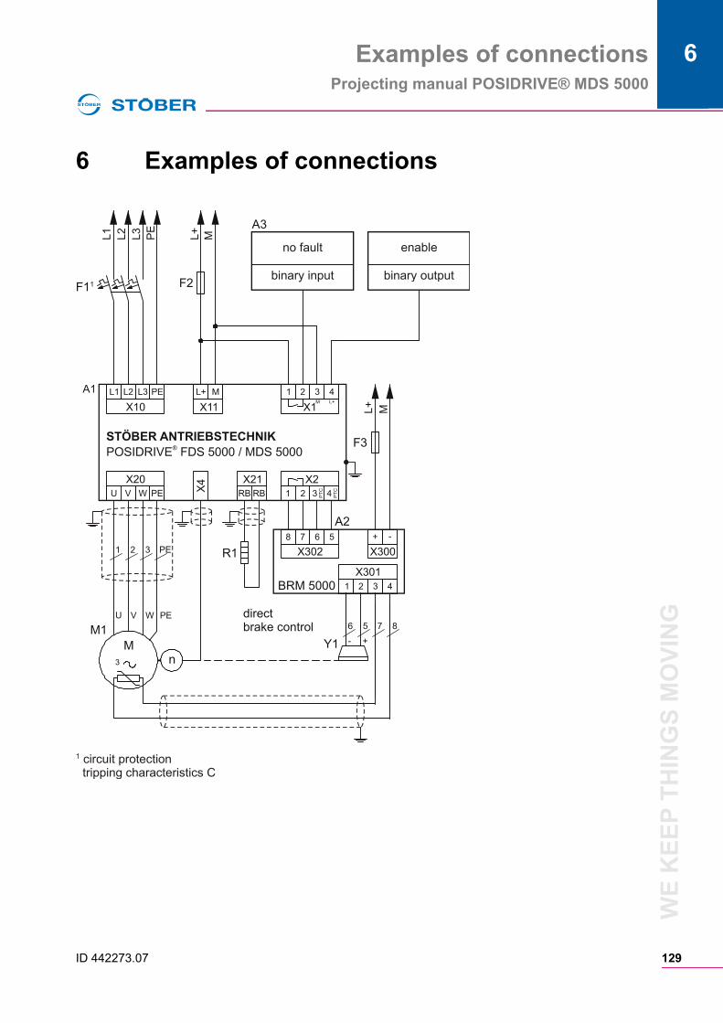
Examples of connectionsProjecting manual POSIDRIVE® MDS 5000
WE
KE
EP
TH
ING
S M
OV
ING
6
6 Examples of connections
M3 n
STÖBER ANTRIEBSTECHNIK
X20
X1X11X10M L+
X21 X2
PT
C
PT
C
BRM 5000
X300X302
X301
L1 L2
U V W PE
M1
L3 PE
L+
F2
L1 L2 L3 PE L+ M 1 2 3 4
U V W PE X4
RB RB 1 2 3 4
A1
M
6 75 8
R1
A3
binary input
no fault
8 7 6 5 + -
1 2 3 4
A2
- +Y1
L+
F3
M
binary output
enable
directbrake control
1 circuit protection tripping characteristics C
F11
1 2 3 PE
ID 442273.07 129
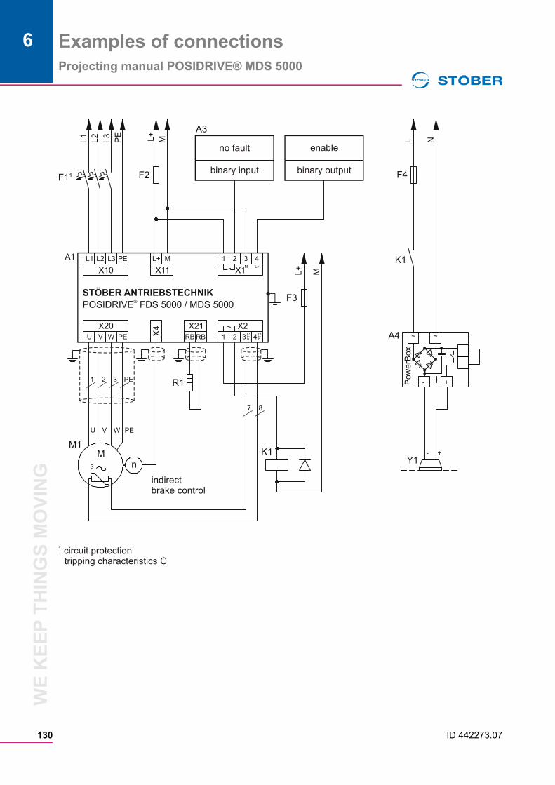
Examples of connections
130
Projecting manual POSIDRIVE® MDS 5000
6W
E K
EE
P T
HIN
GS
MO
VIN
G
binary input
no fault
binary output
enable
indirectbrake control
1 circuit protection tripping characteristics C
M3 n
X20
X1X11X10M L+
X21 X2
PT
C
PT
C
L1
L2
U V W PE
M1
L3
PE L+
F2
L1 L2 L3 PE L+ M 1 2 3 4
U V W PE X4
RB RB 1 2 3 4
A1
M
R1
A3
K1
L+F3
M
L
F4
K1
A4
- +Y1
N
STÖBER ANTRIEBSTECHNIK
F11
7 8
1 2 3 PE Pow
erB
ox
~ ~
- +
ID 442273.07
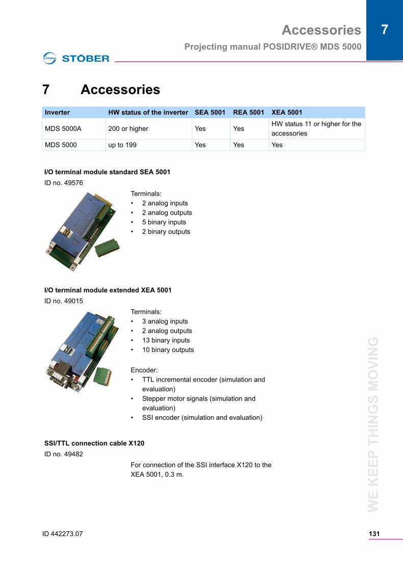
AccessoriesProjecting manual POSIDRIVE® MDS 5000
WE
KE
EP
TH
ING
S M
OV
ING
7
7 Accessories
Inverter HW status of the inverter SEA 5001 REA 5001 XEA 5001
MDS 5000A 200 or higher Yes YesHW status 11 or higher for the
accessories
MDS 5000 up to 199 Yes Yes Yes
I/O terminal module standard SEA 5001
ID no. 49576
Terminals:
• 2 analog inputs
• 2 analog outputs
• 5 binary inputs
• 2 binary outputs
I/O terminal module extended XEA 5001
ID no. 49015
Terminals:
• 3 analog inputs
• 2 analog outputs
• 13 binary inputs
• 10 binary outputs
Encoder:
• TTL incremental encoder (simulation and
evaluation)
• Stepper motor signals (simulation and
evaluation)
• SSI encoder (simulation and evaluation)
SSI/TTL connection cable X120
ID no. 49482
For connection of the SSI interface X120 to the
XEA 5001, 0.3 m.
ID 442273.07 131
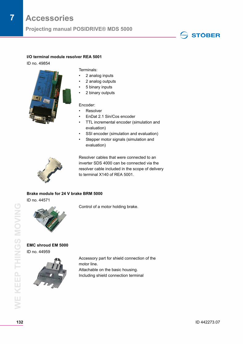
Accessories
132
Projecting manual POSIDRIVE® MDS 5000
7W
E K
EE
P T
HIN
GS
MO
VIN
G
I/O terminal module resolver REA 5001
ID no. 49854
Terminals:
• 2 analog inputs
• 2 analog outputs
• 5 binary inputs
• 2 binary outputs
Encoder:
• Resolver
• EnDat 2.1 Sin/Cos encoder
• TTL incremental encoder (simulation and
evaluation)
• SSI encoder (simulation and evaluation)
• Stepper motor signals (simulation and
evaluation)
Resolver cables that were connected to an
inverter SDS 4000 can be connected via the
resolver cable included in the scope of delivery
to terminal X140 of REA 5001.
Brake module for 24 V brake BRM 5000
ID no. 44571
Control of a motor holding brake.
EMC shroud EM 5000
ID no. 44959
Accessory part for shield connection of the
motor line.
Attachable on the basic housing.
Including shield connection terminal
ID 442273.07

AccessoriesProjecting manual POSIDRIVE® MDS 5000
WE
KE
EP
TH
ING
S M
OV
ING
7
EMC shroud EM6A3
ID no. 135120
EMC shroud for size 3.
Accessory part for shield connection of the
motor line. Attachable on the basic housing.
Including shield connection terminal for power
cable cross-sections of 6 to 25 mm².
If necessary you can also connect the cable
shield of the braking resistor and DC link
connection on the shroud. Additional shield
connection terminals are available as
accessories for this purpose.
4-way axis switcher POSISwitch AX 5000
ID no. 49578
Enables the operation of up to four servo motors
on one inverter.
POSISwitch connection cable
Connection between inverter and POSISwitch
AX 5000.
The following versions are available:
ID no. 45405: 0.5 m.
ID no. 45386: 2.5 m.
Absolute Encoder Support AES
ID no. 55452
ID 442273.07 133

Accessories
134
Projecting manual POSIDRIVE® MDS 5000
7W
E K
EE
P T
HIN
GS
MO
VIN
G
For buffering the power supply when using the
inductive Multiturn EnDat 2.2 absolute encoder
EBI1135 when the 24 vdc power supply is
switched off at the inverter.
A battery is included.
Replaceable battery AES
ID no. 55453
Replaceable battery for Absolute Encoder
Support AES.
ID 442273.07
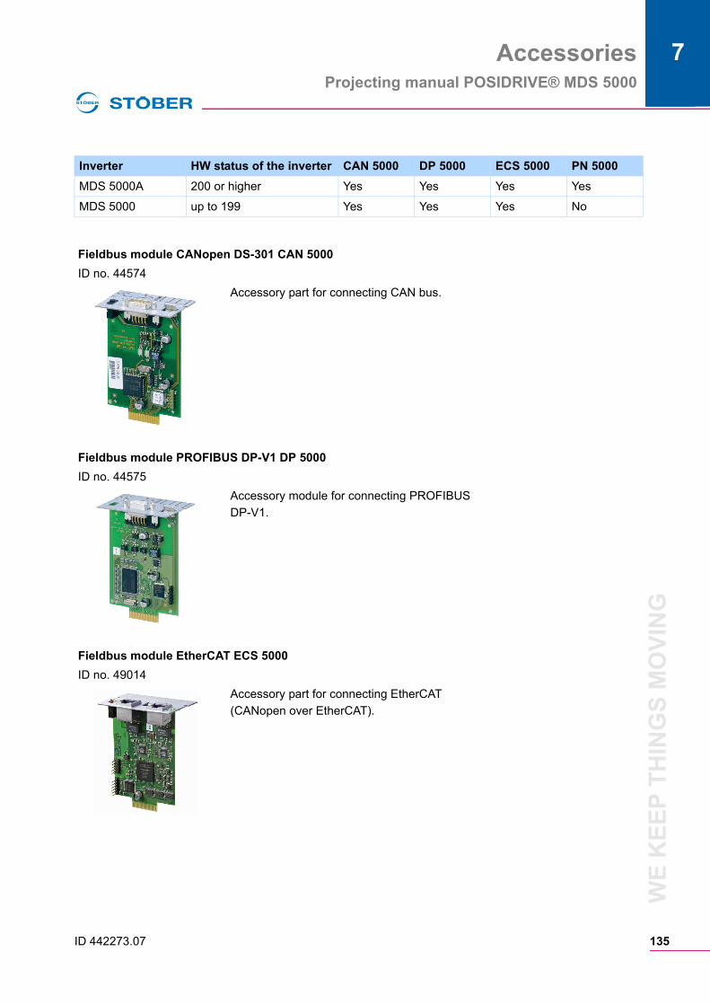
AccessoriesProjecting manual POSIDRIVE® MDS 5000
WE
KE
EP
TH
ING
S M
OV
ING
7
Inverter HW status of the inverter CAN 5000 DP 5000 ECS 5000 PN 5000
MDS 5000A 200 or higher Yes Yes Yes Yes
MDS 5000 up to 199 Yes Yes Yes No
Fieldbus module CANopen DS-301 CAN 5000
ID no. 44574
Accessory part for connecting CAN bus.
Fieldbus module PROFIBUS DP-V1 DP 5000
ID no. 44575
Accessory module for connecting PROFIBUS
DP-V1.
Fieldbus module EtherCAT ECS 5000
ID no. 49014
Accessory part for connecting EtherCAT
(CANopen over EtherCAT).
ID 442273.07 135
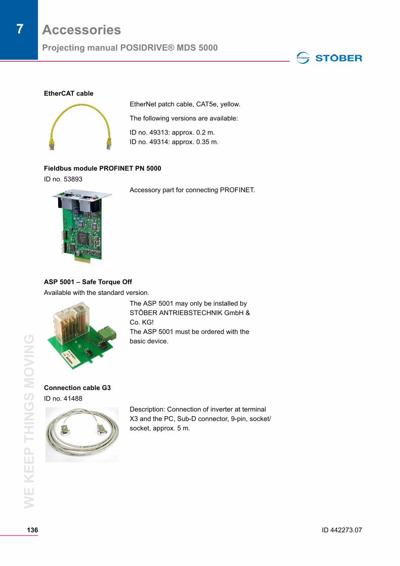
Accessories
136
Projecting manual POSIDRIVE® MDS 5000
7W
E K
EE
P T
HIN
GS
MO
VIN
G
EtherCAT cable
EtherNet patch cable, CAT5e, yellow.
The following versions are available:
ID no. 49313: approx. 0.2 m.
ID no. 49314: approx. 0.35 m.
Fieldbus module PROFINET PN 5000
ID no. 53893
Accessory part for connecting PROFINET.
ASP 5001 – Safe Torque Off
Available with the standard version.
The ASP 5001 may only be installed by
STÖBER ANTRIEBSTECHNIK GmbH & Co. KG!
The ASP 5001 must be ordered with the basic device.
Connection cable G3
ID no. 41488
Description: Connection of inverter at terminal
X3 and the PC, Sub-D connector, 9-pin, socket/
socket, approx. 5 m.
ID 442273.07
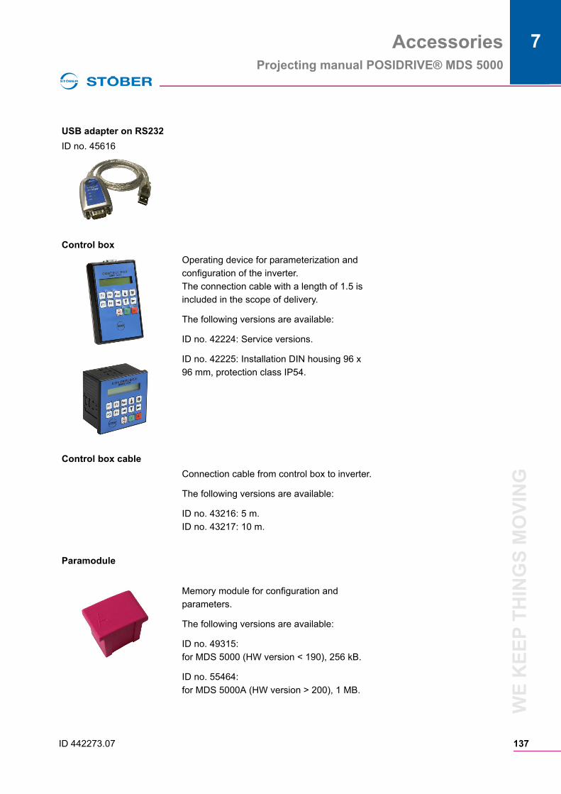
AccessoriesProjecting manual POSIDRIVE® MDS 5000
WE
KE
EP
TH
ING
S M
OV
ING
7
USB adapter on RS232
ID no. 45616
Control box
Operating device for parameterization and
configuration of the inverter.
The connection cable with a length of 1.5 is
included in the scope of delivery.
The following versions are available:
ID no. 42224: Service versions.
ID no. 42225: Installation DIN housing 96 x
96 mm, protection class IP54.
Control box cable
Connection cable from control box to inverter.
The following versions are available:
ID no. 43216: 5 m.
ID no. 43217: 10 m.
Paramodule
Memory module for configuration and
parameters.
The following versions are available:
ID no. 49315: for MDS 5000 (HW version < 190), 256 kB.
ID no. 55464: for MDS 5000A (HW version > 200), 1 MB.
ID 442273.07 137

Notes
WE
KE
EP
TH
ING
S M
OV
ING
Global presence
Address registers
Always up to date on the internet: www.stober.com (Contact)
• Technical offices for advice and marketing in Germany
• Global presence for advice and marketing in about 25 countries
• Service network Germany
• Service network international
• STOBER subsidiaries:
Austria
Switzerland
China
USA
Great Britain
Japan
France
Italy
Singapore
STÖBER ANTRIEBSTECHNIK GmbHHauptstraße 41a4663 LaakirchenFon +43 7613 7600-0Fax +43 7613 7600-2525E-Mail: [email protected]
STÖBER SCHWEIZ AGRugghölzli 25453 RemetschwilFon +41 56 496 96 50 Fax +41 56 496 96 55eMail: [email protected]
STOBER CHINAGerman Centre BeijingUnit 2010, Landmark Tower 2,8 North Dongsanhuan RoadChaoyang District100004 BeijingFon +86 10 65907391Fax +86 10 65907393 eMail: [email protected]
STOBER DRIVES INC.1781 Downing DriveMaysville, KY 41056Fon +1 606 7595090 Fax +1 606 7595045eMail: [email protected]
STOBER DRIVES LTD.Upper Keys Business VillageKeys Park Road, HednesfordCannock WS12 2HAFon +44 1543 458 858Fax +44 1543 448 688E-Mail: [email protected]
STOBER JapanP.O. Box 113-002, 6 chome15-8, Hon-komagomeBunkyo-kuTokyoFon +81 3 5395-6788Fax +81 3 5395-6799 eMail: [email protected]
STÖBER S.a.r.l.131, Chemin du Bac à TrailleLes Portes du Rhône69300 Caluire et CuireFon +33 4 78989180 Fax +33 4 78985901eMail: [email protected]
STÖBER TRASMISSIONI S. r. l.Via Italo Calvino, 7 Palazzina D20017 Rho (MI)Fon +39 02 93909-570 Fax +39 02 93909-325eMail: [email protected]
STOBER Singapore Pte. Ltd.50 Tagore Lane#05-06BEntrepreneur CentreSingapore 787494Fon +65 65112912Fax +65 65112969 E-Mail: [email protected]
ww
w.s
tob
er.c
om
m
STÖBER ANTRIEBSTECHNIK GmbH & Co. KGKieselbronner Str. 1275177 PFORZHEIMGERMANYTel. +49 7231 582-0Fax. +49 7231 582-1000E-Mail: [email protected]
24/h service hotline +49 180 5 786 323
Technische Änderungen vorbehaltenErrors and changes exceptedID 442273.0703/2015
442273.07
www.stober.com


![Portable LED Luminaire - Candilux GmbH · 2016. 2. 25. · 6600 6600 9400 9400 28200 39600 122 105 122 101 109 97 Correlated Colour Temperature [K] 5000 5000 5000 5000 5000 5000 Rated](https://img.pdfslide.us/doc/110x75/611b2b29098d3326ef3bd61d/portable-led-luminaire-candilux-gmbh-2016-2-25-6600-6600-9400-9400-28200.jpg)