Embed Size (px)
Citation preview

Poseidon family - Manual HW group
www.HW-group.com 1 / 105
Poseidon family
Poseidon family - Manual HW group
www.HW-group.com 2 / 105
First steps with Poseidon
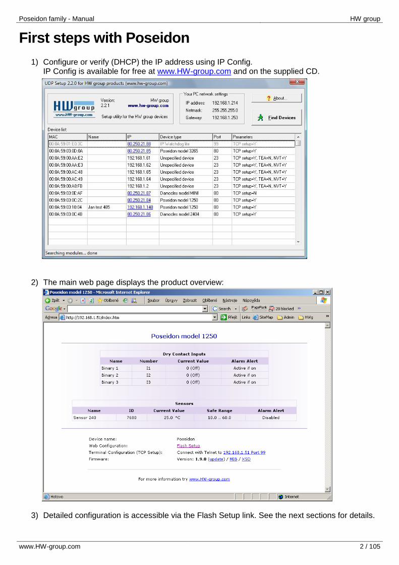
1) Configure or verify (DHCP) the IP address using IP Config. IP Config is available for free at www.HW-group.com and on the supplied CD.
2) The main web page displays the product overview:
3) Detailed configuration is accessible via the Flash Setup link. See the next sections for details.
Poseidon family - Manual HW group
www.HW-group.com 3 / 105
Connecting the sensors
1-Wire / 1-Wire UNI (RJ11)
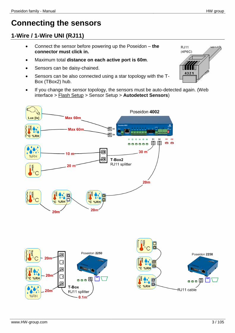
Connect the sensor before powering up the Poseidon – the connector must click in.
Maximum total distance on each active port is 60m.
Sensors can be daisy-chained.
Sensors can be also connected using a star topology with the T-Box (TBox2) hub.
If you change the sensor topology, the sensors must be auto-detected again. (Web interface > Flash Setup > Sensor Setup > Autodetect Sensors)
Poseidon family - Manual HW group
www.HW-group.com 4 / 105
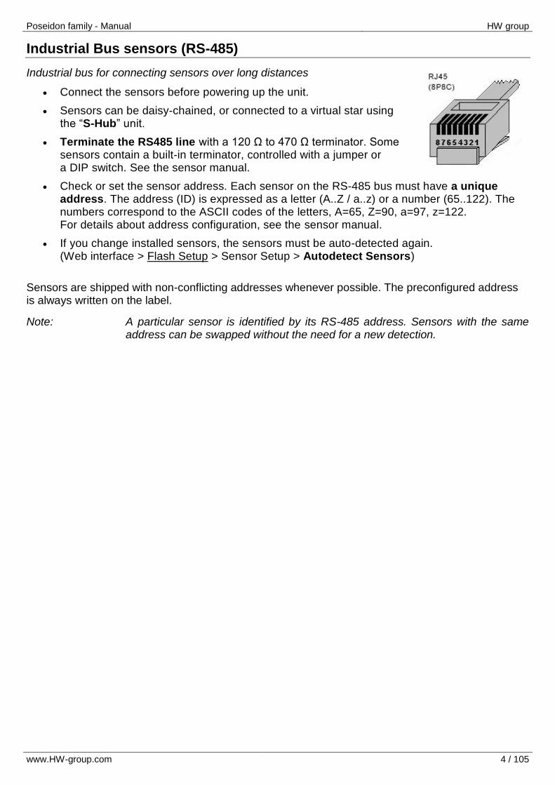
Industrial Bus sensors (RS-485)
Industrial bus for connecting sensors over long distances
Connect the sensors before powering up the unit.
Sensors can be daisy-chained, or connected to a virtual star using the “S-Hub” unit.
Terminate the RS485 line with a 120 Ω to 470 Ω terminator. Some sensors contain a built-in terminator, controlled with a jumper or a DIP switch. See the sensor manual.
Check or set the sensor address. Each sensor on the RS-485 bus must have a unique address. The address (ID) is expressed as a letter (A..Z / a..z) or a number (65..122). The numbers correspond to the ASCII codes of the letters, A=65, Z=90, a=97, z=122. For details about address configuration, see the sensor manual.
If you change installed sensors, the sensors must be auto-detected again. (Web interface > Flash Setup > Sensor Setup > Autodetect Sensors)
Sensors are shipped with non-conflicting addresses whenever possible. The preconfigured address is always written on the label.
Note: A particular sensor is identified by its RS-485 address. Sensors with the same address can be swapped without the need for a new detection.
Poseidon family - Manual HW group
www.HW-group.com 5 / 105
Common features of the Poseidon product line
Displayed readings
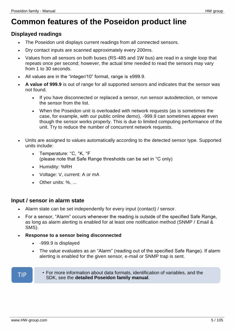
The Poseidon unit displays current readings from all connected sensors.
Dry contact inputs are scanned approximately every 200ms.
Values from all sensors on both buses (RS-485 and 1W bus) are read in a single loop that repeats once per second; however, the actual time needed to read the sensors may vary from 1 to 30 seconds.
All values are in the “integer/10” format, range is ±999.9.
A value of 999.9 is out of range for all supported sensors and indicates that the sensor was not found.
If you have disconnected or replaced a sensor, run sensor autodetection, or remove the sensor from the list.
When the Poseidon unit is overloaded with network requests (as is sometimes the case, for example, with our public online demo), -999.9 can sometimes appear even though the sensor works properly. This is due to limited computing performance of the unit. Try to reduce the number of concurrent network requests.
Units are assigned to values automatically according to the detected sensor type. Supported units include:
Temperature: °C, °K, °F (please note that Safe Range thresholds can be set in °C only)
Humidity: %RH
Voltage: V, current: A or mA
Other units: %, ...
Input / sensor in alarm state
Alarm state can be set independently for every input (contact) / sensor.
For a sensor, “Alarm” occurs whenever the reading is outside of the specified Safe Range, as long as alarm alerting is enabled for at least one notification method (SNMP / Email & SMS).
Response to a sensor being disconnected
-999.9 is displayed
The value evaluates as an “Alarm” (reading out of the specified Safe Range). If alarm alerting is enabled for the given sensor, e-mail or SNMP trap is sent.
• For more information about data formats, identification of variables, and the SDK, see the detailed Poseidon family manual. TIP
Poseidon family - Manual HW group
www.HW-group.com 6 / 105
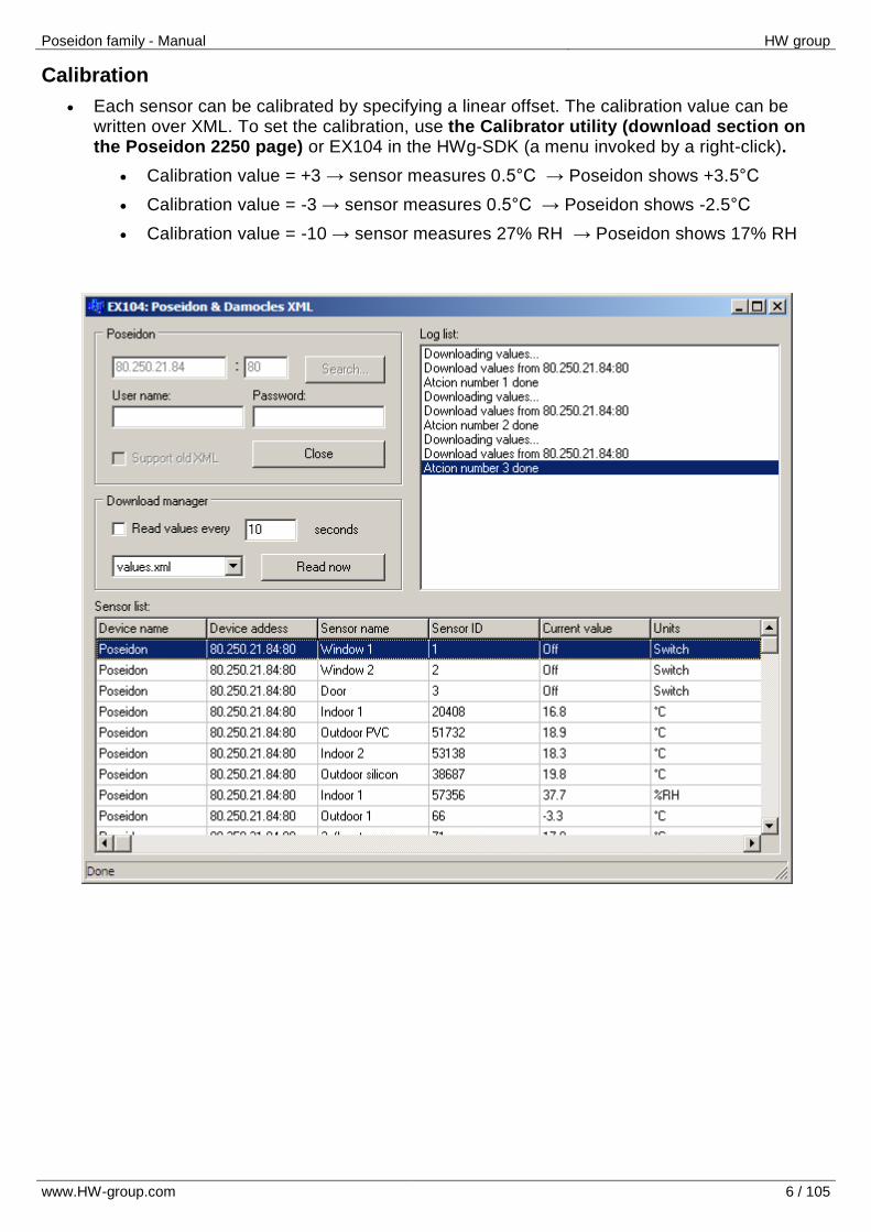
Calibration
Each sensor can be calibrated by specifying a linear offset. The calibration value can be written over XML. To set the calibration, use the Calibrator utility (download section on the Poseidon 2250 page) or EX104 in the HWg-SDK (a menu invoked by a right-click).
Calibration value = +3 → sensor measures 0.5°C → Poseidon shows +3.5°C
Calibration value = -3 → sensor measures 0.5°C → Poseidon shows -2.5°C
Calibration value = -10 → sensor measures 27% RH → Poseidon shows 17% RH
Poseidon family - Manual HW group
www.HW-group.com 7 / 105
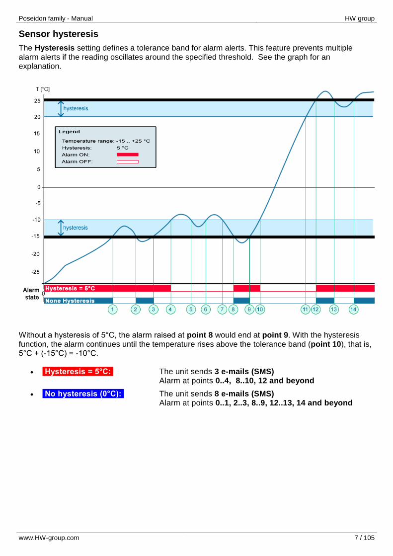
Sensor hysteresis
The Hysteresis setting defines a tolerance band for alarm alerts. This feature prevents multiple alarm alerts if the reading oscillates around the specified threshold. See the graph for an explanation.
Without a hysteresis of 5°C, the alarm raised at point 8 would end at point 9. With the hysteresis function, the alarm continues until the temperature rises above the tolerance band (point 10), that is, 5°C + (-15°C) = -10°C.
Hysteresis = 5°C: The unit sends 3 e-mails (SMS) Alarm at points 0..4, 8..10, 12 and beyond
No hysteresis (0°C): The unit sends 8 e-mails (SMS) Alarm at points 0..1, 2..3, 8..9, 12..13, 14 and beyond

Poseidon family - Manual HW group
www.HW-group.com 8 / 105
Overview of the Poseidon product line
Poseidon models
The Poseidon family consists of several models targeted at various applications and markets. Common features:
Unified, easy-to-install graphical interface
Mutually compatible network communication protocols
Range of inputs, outputs and sensors, several budget levels
3266
3268
3468
2250
4002
WEB interface Yes Yes Yes Yes Yes
Binary (dry contact) inputs 4 4 4 3 6
Outputs (contacts) - 2 2 2** 2
1-Wire Bus 1Wire Bus UNI
3 -
4 -
10 -
10
Yes
12
Yes
Industrial bus (RS485) - - - 28 -
Logger - - - Yes -
HTML, XML Yes Yes Yes Yes Yes
SMTP Email Yes Yes Yes Yes Yes
Periodic reminder (Email) - - - Yes Yes
SNMP (R/W), Trap Yes Yes Yes Yes Yes
Modbus/TCP Yes - - Yes -
Alarm SMS (with an external GSM modem)
- - - Yes Yes
*) GSM supported only by older firmware 1.9.11 **) Outputs on the RS-232 interface only. No local conditions, if used with GSM modem together require split cable
Poseidon family - Manual HW group
www.HW-group.com 9 / 105
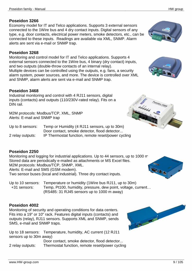
Poseidon 3266 Economy model for IT and Telco applications. Supports 3 external sensors connected to the 1Wire bus and 4 dry contact inputs. Digital sensors of any type, e.g. door contacts, electrical power meters, smoke detectors, etc., can be connected to these inputs. Readings are available via XML, SNMP. Alarm alerts are sent via e-mail or SNMP trap.
Poseidon 3268 Monitoring and control model for IT and Telco applications. Supports 4 external sensors connected to the 1Wire bus, 4 binary (dry contact) inputs, and two outputs (double-throw contacts of an internal relay). Multiple devices can be controlled using the outputs, e.g. fans, a security alarm system, power sources, and more. The device is controlled over XML and SNMP, alarm alerts are sent via e-mail and SNMP trap.
Poseidon 3468 Industrial monitoring and control with 4 RJ11 sensors, digital inputs (contacts) and outputs (110/230V-rated relay). Fits on a DIN rail. M2M protocols: Modbus/TCP, XML, SNMP Alerts: E-mail and SNMP trap Up to 8 sensors: Temp or Humidity (4 RJ11 sensors, up to 30m) Door contact, smoke detector, flood detector... 2 relay outputs: IP Thermostat function, remote reset/power cycling
Poseidon 2250 Monitoring and logging for industrial applications. Up to 44 sensors, up to 1000 m. Stored data are periodically e-mailed as attachments or MS Excel files. M2M protocols: Modbus/TCP, SNMP, XML. Alerts: E-mail and SMS (GSM modem). Two sensor buses (local and industrial). Three dry contact inputs. Up to 10 sensors: Temperature or humidity (1Wire bus RJ11, up to 30m) +31 sensors: Temp, Pt100, humidity, pressure, dew point, voltage, current…
(RS485: 31 RJ45 sensors up to 1000 m away)
Poseidon 4002 Monitoring of security and operating conditions for data centers. Fits into a 19" or 10" rack. Features digital inputs (contacts) and outputs (relay), RJ11 sensors. Supports XML and SNMP, sends SMS, e-mail and SNMP traps. Up to 18 sensors: Temperature, humidity, AC current (12 RJ11 sensors up to 30m away) Door contact, smoke detector, flood detector... 2 relay outputs: Thermostat function, remote reset/power cycling
Poseidon family - Manual HW group
www.HW-group.com 10 / 105
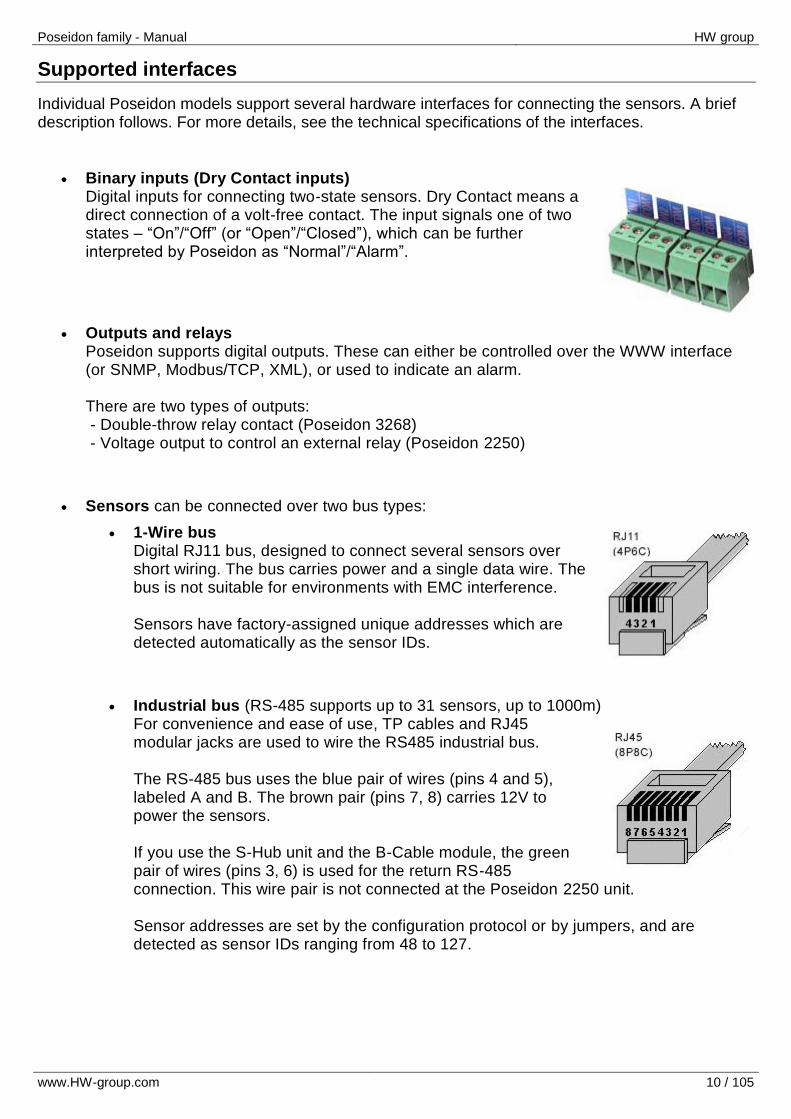
Supported interfaces
Individual Poseidon models support several hardware interfaces for connecting the sensors. A brief description follows. For more details, see the technical specifications of the interfaces.
Binary inputs (Dry Contact inputs) Digital inputs for connecting two-state sensors. Dry Contact means a direct connection of a volt-free contact. The input signals one of two states – “On”/“Off” (or “Open”/“Closed”), which can be further interpreted by Poseidon as “Normal”/“Alarm”.
Outputs and relays Poseidon supports digital outputs. These can either be controlled over the WWW interface (or SNMP, Modbus/TCP, XML), or used to indicate an alarm. There are two types of outputs: - Double-throw relay contact (Poseidon 3268) - Voltage output to control an external relay (Poseidon 2250)
Sensors can be connected over two bus types:
1-Wire bus Digital RJ11 bus, designed to connect several sensors over short wiring. The bus carries power and a single data wire. The bus is not suitable for environments with EMC interference. Sensors have factory-assigned unique addresses which are detected automatically as the sensor IDs.
Industrial bus (RS-485 supports up to 31 sensors, up to 1000m) For convenience and ease of use, TP cables and RJ45 modular jacks are used to wire the RS485 industrial bus. The RS-485 bus uses the blue pair of wires (pins 4 and 5), labeled A and B. The brown pair (pins 7, 8) carries 12V to power the sensors. If you use the S-Hub unit and the B-Cable module, the green pair of wires (pins 3, 6) is used for the return RS-485 connection. This wire pair is not connected at the Poseidon 2250 unit. Sensor addresses are set by the configuration protocol or by jumpers, and are detected as sensor IDs ranging from 48 to 127.
Poseidon family - Manual HW group
www.HW-group.com 11 / 105
Detailed interface description
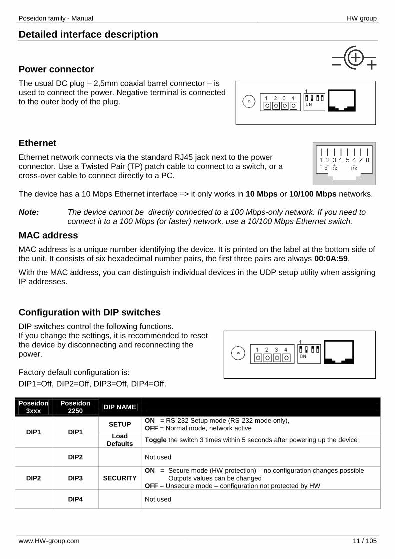
Power connector
The usual DC plug – 2,5mm coaxial barrel connector – is used to connect the power. Negative terminal is connected to the outer body of the plug.
Ethernet
Ethernet network connects via the standard RJ45 jack next to the power connector. Use a Twisted Pair (TP) patch cable to connect to a switch, or a cross-over cable to connect directly to a PC. The device has a 10 Mbps Ethernet interface => it only works in 10 Mbps or 10/100 Mbps networks. Note: The device cannot be directly connected to a 100 Mbps-only network. If you need to
connect it to a 100 Mbps (or faster) network, use a 10/100 Mbps Ethernet switch.
MAC address
MAC address is a unique number identifying the device. It is printed on the label at the bottom side of the unit. It consists of six hexadecimal number pairs, the first three pairs are always 00:0A:59.
With the MAC address, you can distinguish individual devices in the UDP setup utility when assigning IP addresses.
Configuration with DIP switches
DIP switches control the following functions. If you change the settings, it is recommended to reset the device by disconnecting and reconnecting the power. Factory default configuration is:
DIP1=Off, DIP2=Off, DIP3=Off, DIP4=Off.
Poseidon 3xxx
Poseidon 2250
DIP NAME
DIP1 DIP1 SETUP
ON = RS-232 Setup mode (RS-232 mode only), OFF = Normal mode, network active
Load Defaults
Toggle the switch 3 times within 5 seconds after powering up the device
DIP2 Not used
DIP2 DIP3 SECURITY ON = Secure mode (HW protection) – no configuration changes possible Outputs values can be changed OFF = Unsecure mode – configuration not protected by HW
DIP4 Not used
Poseidon family - Manual HW group
www.HW-group.com 12 / 105
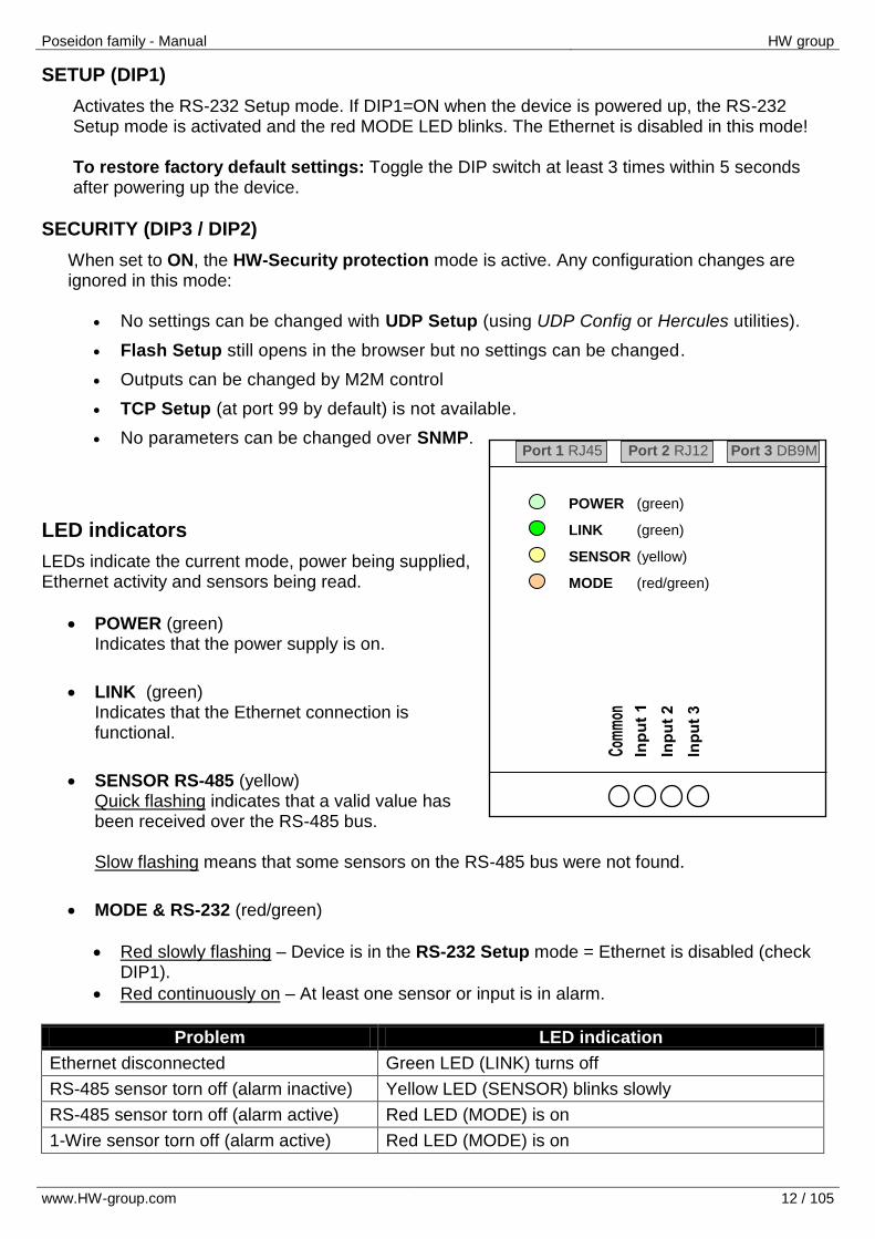
POWER (green)
LINK (green)
SENSOR (yellow)
MODE (red/green)
Port 1 RJ45 Port 2 RJ12 Port 3 DB9M
SETUP (DIP1)
Activates the RS-232 Setup mode. If DIP1=ON when the device is powered up, the RS-232 Setup mode is activated and the red MODE LED blinks. The Ethernet is disabled in this mode! To restore factory default settings: Toggle the DIP switch at least 3 times within 5 seconds after powering up the device.
SECURITY (DIP3 / DIP2)
When set to ON, the HW-Security protection mode is active. Any configuration changes are ignored in this mode:
No settings can be changed with UDP Setup (using UDP Config or Hercules utilities).
Flash Setup still opens in the browser but no settings can be changed.
Outputs can be changed by M2M control
TCP Setup (at port 99 by default) is not available.
No parameters can be changed over SNMP.
LED indicators
LEDs indicate the current mode, power being supplied, Ethernet activity and sensors being read.
POWER (green) Indicates that the power supply is on.
LINK (green) Indicates that the Ethernet connection is functional.
SENSOR RS-485 (yellow) Quick flashing indicates that a valid value has been received over the RS-485 bus. Slow flashing means that some sensors on the RS-485 bus were not found.
MODE & RS-232 (red/green)
Red slowly flashing – Device is in the RS-232 Setup mode = Ethernet is disabled (check DIP1).
Red continuously on – At least one sensor or input is in alarm.
Problem LED indication
Ethernet disconnected Green LED (LINK) turns off
RS-485 sensor torn off (alarm inactive) Yellow LED (SENSOR) blinks slowly
RS-485 sensor torn off (alarm active) Red LED (MODE) is on
1-Wire sensor torn off (alarm active) Red LED (MODE) is on

Poseidon family - Manual HW group
www.HW-group.com 13 / 105
DB9M - RS-232
The interface is intended for setting up the device (RS-232 Setup when DIP1=ON) and for updating the firmware. The DTR and RTS outputs can be controlled from the Flash setup interface, tied to an alarm state, or controlled over the network. Voltages corresponding to logic levels on these outputs:
RTS
0 (Off) = -10V (-12..-6V)
1 (On) = +10V (6..12V)
DTR
0 (Off) = 0V
1 (On) = +10V (6..12V)
States of outputs after device restart: RTS = Off (-10V), DTR = Off (0V).
Using the RTS and DTR outputs Port 3 complies with the RS-232 specification. If needed, the P1250 RC converter (designed for connecting two 12VDC rated relays to Poseidon 2250 over RS-232) can be used to connect two external relays. The converter applies approximately 10V to the relay coil, making it possible to control 9VDC or 12VDC rated relays.
P1250 RC (Relay Cable) - Ordering No. 600 244 Relay coils connect directly to a small terminal block. Polarity is shown on the label, closed state is indicated by a LED lighting up.
DB9M
1 - - Not used
2 RxD <-- Receive Data
3 TxD --> Transmit Data
4 DTR --> Data Terminal Ready
5 GND --- System Ground
6 DSR <-- Data Set Ready
7 RTS --> Request to Send
8 CTS <-- Clear to Send
9 - - Not used
Poseidon family - Manual HW group
www.HW-group.com 14 / 105
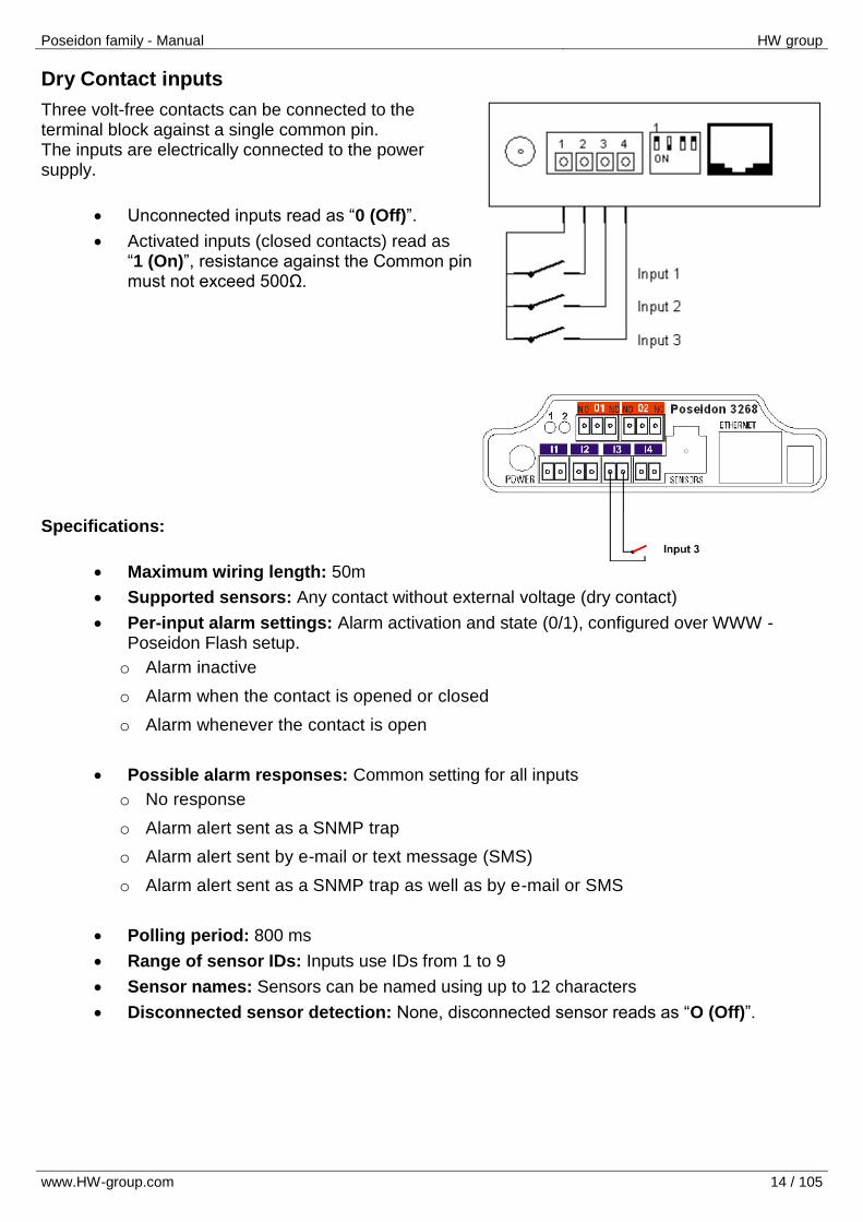
Dry Contact inputs
Three volt-free contacts can be connected to the terminal block against a single common pin. The inputs are electrically connected to the power supply.
Unconnected inputs read as “0 (Off)”.
Activated inputs (closed contacts) read as “1 (On)”, resistance against the Common pin must not exceed 500Ω.
Specifications:
Maximum wiring length: 50m
Supported sensors: Any contact without external voltage (dry contact)
Per-input alarm settings: Alarm activation and state (0/1), configured over WWW - Poseidon Flash setup.
o Alarm inactive
o Alarm when the contact is opened or closed
o Alarm whenever the contact is open
Possible alarm responses: Common setting for all inputs
o No response
o Alarm alert sent as a SNMP trap
o Alarm alert sent by e-mail or text message (SMS)
o Alarm alert sent as a SNMP trap as well as by e-mail or SMS
Polling period: 800 ms
Range of sensor IDs: Inputs use IDs from 1 to 9
Sensor names: Sensors can be named using up to 12 characters
Disconnected sensor detection: None, disconnected sensor reads as “O (Off)”.

Poseidon family - Manual HW group
www.HW-group.com 15 / 105
RJ11 – 1-Wire or 1W sensors
The digital bus from Dallas Semiconductor company, each sensor has unique ID. We recommend to keep the total wiring length under 60m, although functionality has been achieved over tens to hundreds of meters in experimental settings. If the wiring connected to a single connector of the Poseidon unit is longer than approximately 80m, we cannot guarantee error-free operation, as it greatly depends on the actual wiring implementation, topology and environment.
Active / Passive 1W port Active port is RJ11 connector on the Poseidon device. It guarantees full length of wiring and power for defined quantity of 1-Wire or 1-Wire UNI sensors. When you move the sensor from one active port to other one, the sensors seems to be disconnected. You have to run sensors auto-detection again. Passive port is RJ11 connector on T-Hub splitter or on the 1-Wire sensor in daisy-chain wiring. It can’t guarantee full length and full power for all following sensors. The power issue can be solved with using the 1-Wire hub Power.
1-Wire UNI (RJ11)
1-Wire UNI is software extension of the 1-Wire bus.
1-Wire UNI sensors: o Light sensor o 4-20mA sensor o 0-60V (-48V DC) sensor o 0-30A AC sensor o >>Various other sensors
Maximum wiring length : 60 meters of total length per active RJ11 port
Note: Distance can be limited with some 1-Wire UNI sensors or with more RJ11 male-female connectors.
Sensor power supply: 5V/20 mA from RJ11 connector (can be boosted by "1-Wire hub Power")
Other parameters or 1-Wire UNI are identical with 1-Wire bus.
Port 1 – RJ12
1 +5V Power
2 - Not used
3 Data Transmit Data
4 GND Ground
5 +5V Power
6 - Not used
Poseidon family - Manual HW group
www.HW-group.com 16 / 105
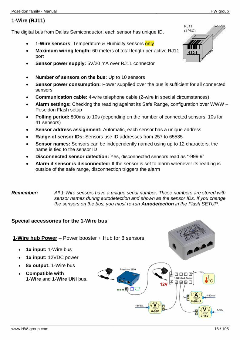
1-Wire (RJ11)
The digital bus from Dallas Semiconductor, each sensor has unique ID.
1-Wire sensors: Temperature & Humidity sensors only
Maximum wiring length: 60 meters of total length per active RJ11 port
Sensor power supply: 5V/20 mA over RJ11 connector
Number of sensors on the bus: Up to 10 sensors
Sensor power consumption: Power supplied over the bus is sufficient for all connected sensors
Communication cable: 4-wire telephone cable (2-wire in special circumstances)
Alarm settings: Checking the reading against its Safe Range, configuration over WWW – Poseidon Flash setup
Polling period: 800ms to 10s (depending on the number of connected sensors, 10s for 41 sensors)
Sensor address assignment: Automatic, each sensor has a unique address
Range of sensor IDs: Sensors use ID addresses from 257 to 65535
Sensor names: Sensors can be independently named using up to 12 characters, the name is tied to the sensor ID
Disconnected sensor detection: Yes, disconnected sensors read as “-999.9”
Alarm if sensor is disconnected: If the sensor is set to alarm whenever its reading is outside of the safe range, disconnection triggers the alarm
Remember: All 1-Wire sensors have a unique serial number. These numbers are stored with
sensor names during autodetection and shown as the sensor IDs. If you change the sensors on the bus, you must re-run Autodetection in the Flash SETUP.
Special accessories for the 1-Wire bus
1-Wire hub Power – Power booster + Hub for 8 sensors
1x input: 1-Wire bus
1x input: 12VDC power
8x output: 1-Wire bus
Compatible with 1-Wire and 1-Wire UNI bus.
Poseidon family - Manual HW group
www.HW-group.com 17 / 105
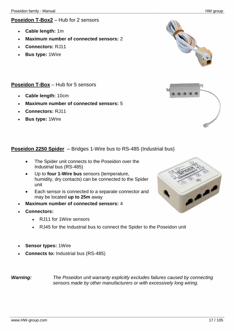
Poseidon T-Box2 – Hub for 2 sensors
Cable length: 1m
Maximum number of connected sensors: 2
Connectors: RJ11
Bus type: 1Wire
Poseidon T-Box – Hub for 5 sensors
Cable length: 10cm
Maximum number of connected sensors: 5
Connectors: RJ11
Bus type: 1Wire
Poseidon 2250 Spider – Bridges 1-Wire bus to RS-485 (Industrial bus)
The Spider unit connects to the Poseidon over the Industrial bus (RS-485)
Up to four 1-Wire bus sensors (temperature, humidity, dry contacts) can be connected to the Spider unit
Each sensor is connected to a separate connector and may be located up to 25m away
Maximum number of connected sensors: 4
Connectors:
RJ11 for 1Wire sensors
RJ45 for the Industrial bus to connect the Spider to the Poseidon unit
Sensor types: 1Wire
Connects to: Industrial bus (RS-485)
Warning: The Poseidon unit warranty explicitly excludes failures caused by connecting
sensors made by other manufacturers or with excessively long wiring.
Poseidon family - Manual HW group
www.HW-group.com 18 / 105
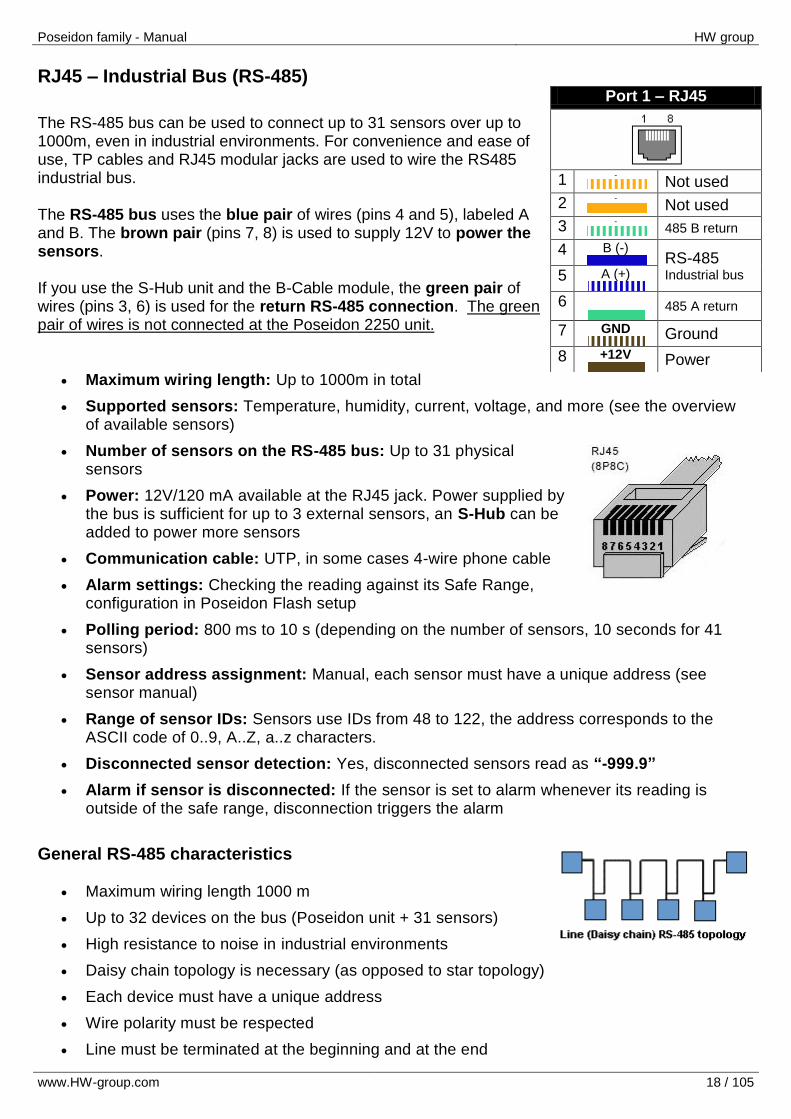
RJ45 – Industrial Bus (RS-485)
The RS-485 bus can be used to connect up to 31 sensors over up to 1000m, even in industrial environments. For convenience and ease of use, TP cables and RJ45 modular jacks are used to wire the RS485 industrial bus. The RS-485 bus uses the blue pair of wires (pins 4 and 5), labeled A and B. The brown pair (pins 7, 8) is used to supply 12V to power the sensors. If you use the S-Hub unit and the B-Cable module, the green pair of wires (pins 3, 6) is used for the return RS-485 connection. The green pair of wires is not connected at the Poseidon 2250 unit.
Maximum wiring length: Up to 1000m in total
Supported sensors: Temperature, humidity, current, voltage, and more (see the overview of available sensors)
Number of sensors on the RS-485 bus: Up to 31 physical sensors
Power: 12V/120 mA available at the RJ45 jack. Power supplied by the bus is sufficient for up to 3 external sensors, an S-Hub can be added to power more sensors
Communication cable: UTP, in some cases 4-wire phone cable
Alarm settings: Checking the reading against its Safe Range, configuration in Poseidon Flash setup
Polling period: 800 ms to 10 s (depending on the number of sensors, 10 seconds for 41 sensors)
Sensor address assignment: Manual, each sensor must have a unique address (see sensor manual)
Range of sensor IDs: Sensors use IDs from 48 to 122, the address corresponds to the ASCII code of 0..9, A..Z, a..z characters.
Disconnected sensor detection: Yes, disconnected sensors read as “-999.9”
Alarm if sensor is disconnected: If the sensor is set to alarm whenever its reading is outside of the safe range, disconnection triggers the alarm
General RS-485 characteristics
Maximum wiring length 1000 m
Up to 32 devices on the bus (Poseidon unit + 31 sensors)
High resistance to noise in industrial environments
Daisy chain topology is necessary (as opposed to star topology)
Each device must have a unique address
Wire polarity must be respected
Line must be terminated at the beginning and at the end
Port 1 – RJ45
1 -
Not used
2 - Not used
3 - 485 B return
4 B (-) RS-485
Industrial bus 5 A (+)
6
485 A return
7 GND
Ground
8 +12V
Power

Poseidon family - Manual HW group
www.HW-group.com 19 / 105
Termination The RS-485 bus must be terminated at its end. The following options are available:
Internal jumper on certain sensors (jumper named TERM or TERMINATOR) – for example in Temp-485 or HTemp-485
B-Cable adapter with “LAST” configuration selected using the switches
External resistor to terminate the bus at the “last” sensor, if the sensor has no jumpers or DIP switches (Temp-485-Pt100). Connect the resistor between the A and B terminals of the last sensor. The resistance of this resistor should be 120Ω. For short wirings, 470Ω can be used to reduce the current consumption of the sensors.
Note: A disadvantage is that it is necessary to have a wiring topology with a single
beginning and a single, terminated end, as opposed to the popular star topology with a single interconnection point.
Special accessories for the RS-485 bus
B-Cable - RJ45 / 4-wire connection The B-Cable module is an adapter that converts a RJ45 jack connection to a block of 4 terminals A,B,+,–. Some of the available RS-485 sensors already have a RJ45 jack; however, some only have 4 terminals labeled A,B,+,- . Such sensors can be connected Poseidon 2250 or to an S-Hub using either a TP cable (4 or 6 wires) or the B-Cable module.
The 4-wire connection length should not exceed 20cm.
Sensor position on the RS-485 bus (MIDDLE / LAST) is selected with jumpers; see the picture for details.
Poseidon family - Manual HW group
www.HW-group.com 20 / 105
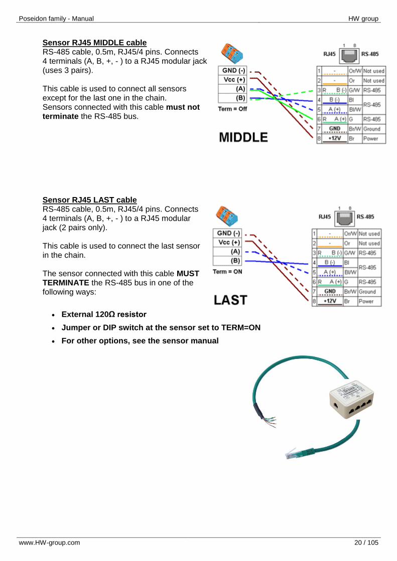
Sensor RJ45 MIDDLE cable RS-485 cable, 0.5m, RJ45/4 pins. Connects 4 terminals (A, B, +, - ) to a RJ45 modular jack (uses 3 pairs). This cable is used to connect all sensors except for the last one in the chain. Sensors connected with this cable must not terminate the RS-485 bus.
Sensor RJ45 LAST cable RS-485 cable, 0.5m, RJ45/4 pins. Connects 4 terminals (A, B, +, - ) to a RJ45 modular jack (2 pairs only). This cable is used to connect the last sensor in the chain. The sensor connected with this cable MUST TERMINATE the RS-485 bus in one of the following ways:
External 120Ω resistor
Jumper or DIP switch at the sensor set to TERM=ON
For other options, see the sensor manual
Poseidon family - Manual HW group
www.HW-group.com 21 / 105
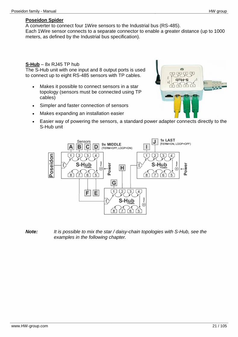
Poseidon Spider A converter to connect four 1Wire sensors to the Industrial bus (RS-485). Each 1Wire sensor connects to a separate connector to enable a greater distance (up to 1000 meters, as defined by the Industrial bus specification). S-Hub – 8x RJ45 TP hub The S-Hub unit with one input and 8 output ports is used to connect up to eight RS-485 sensors with TP cables.
Makes it possible to connect sensors in a star topology (sensors must be connected using TP cables)
Simpler and faster connection of sensors
Makes expanding an installation easier
Easier way of powering the sensors, a standard power adapter connects directly to the S-Hub unit
Note: It is possible to mix the star / daisy-chain topologies with S-Hub, see the
examples in the following chapter.
Poseidon family - Manual HW group
www.HW-group.com 22 / 105
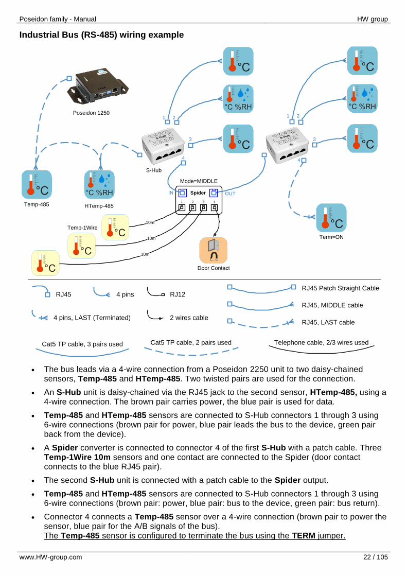
Industrial Bus (RS-485) wiring example
The bus leads via a 4-wire connection from a Poseidon 2250 unit to two daisy-chained sensors, Temp-485 and HTemp-485. Two twisted pairs are used for the connection.
An S-Hub unit is daisy-chained via the RJ45 jack to the second sensor, HTemp-485, using a 4-wire connection. The brown pair carries power, the blue pair is used for data.
Temp-485 and HTemp-485 sensors are connected to S-Hub connectors 1 through 3 using 6-wire connections (brown pair for power, blue pair leads the bus to the device, green pair back from the device).
A Spider converter is connected to connector 4 of the first S-Hub with a patch cable. Three Temp-1Wire 10m sensors and one contact are connected to the Spider (door contact connects to the blue RJ45 pair).
The second S-Hub unit is connected with a patch cable to the Spider output.
Temp-485 and HTemp-485 sensors are connected to S-Hub connectors 1 through 3 using 6-wire connections (brown pair: power, blue pair: bus to the device, green pair: bus return).
Connector 4 connects a Temp-485 sensor over a 4-wire connection (brown pair to power the sensor, blue pair for the A/B signals of the bus). The Temp-485 sensor is configured to terminate the bus using the TERM jumper.
°C %RH
°C
°C °C %RH
°C
°C
°C %RH
°C
°C
RJ45 4 pinsRJ45 Patch Straight Cable
4 pins, LAST (Terminated)
1 2 3 4
Spider
10m
°C
10m
°C10m
°C
Cat5 TP cable, 3 pairs used
RJ12
2 wires cable
Cat5 TP cable, 2 pairs used Telephone cable, 2/3 wires used
RJ45, MIDDLE cable
RJ45, LAST cable
Term=ON
Mode=MIDDLE
Poseidon 1250
Temp-485 HTemp-485
Temp-1Wire
Door Contact
S-Hub
1 2
3
4
IN OUT
1 2
3
4
Poseidon family - Manual HW group
www.HW-group.com 23 / 105
User interface
The product can be configured in various ways which are described in this section, including a description of the parameters.
UDP Config Simple utility for configuring IP addresses (for Windows and Linux).
Web interface Primary communication interface that invokes other links and the Flash setup.
Flash setup Detailed user interface for configuring all features of the device.
Telnet setup Configuration of special features, troubleshooting.
Backing up and restoring configuration How to save and restore product configuration.
For automated configuration or retrieving values in third-party software, use the open communication interfaces described in the following chapter, Using Poseidon units in your programs.
Poseidon family - Manual HW group
www.HW-group.com 24 / 105
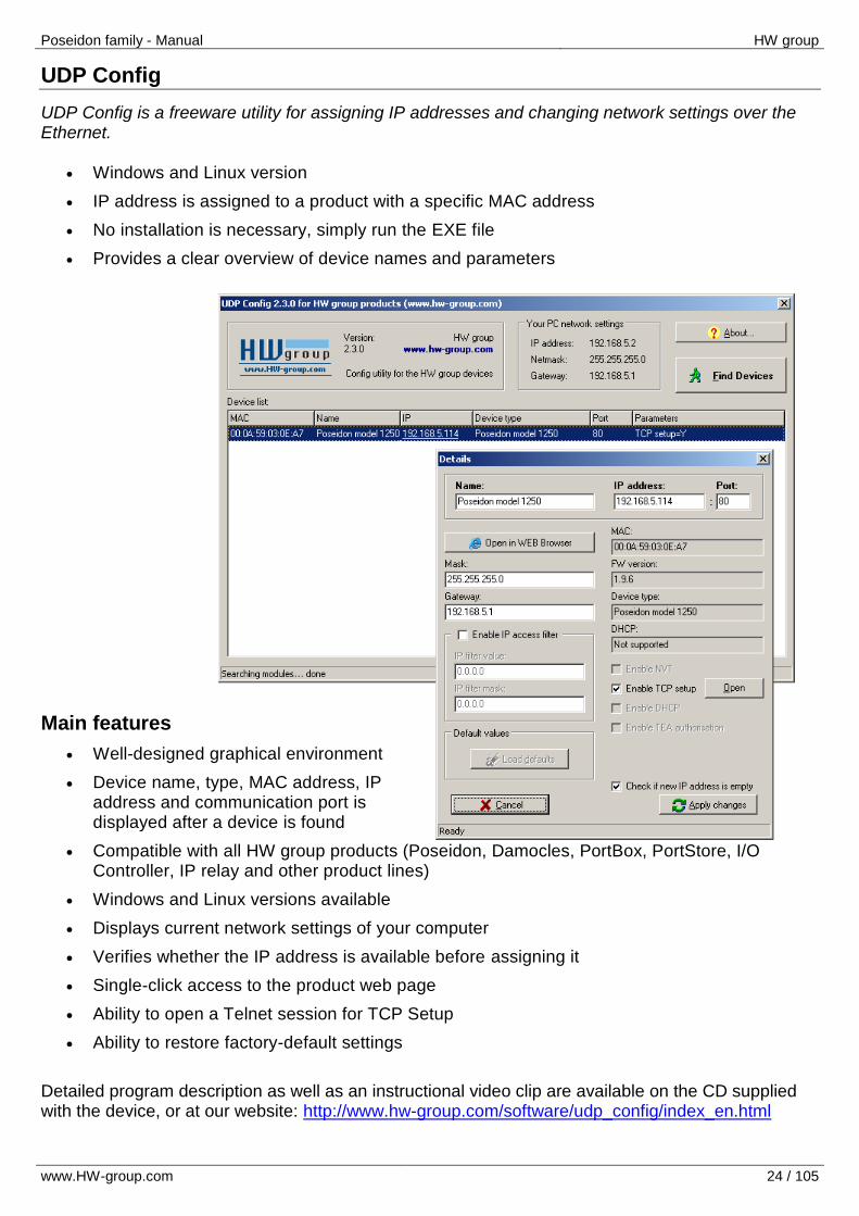
UDP Config
UDP Config is a freeware utility for assigning IP addresses and changing network settings over the Ethernet.
Windows and Linux version
IP address is assigned to a product with a specific MAC address
No installation is necessary, simply run the EXE file
Provides a clear overview of device names and parameters
Main features
Well-designed graphical environment
Device name, type, MAC address, IP address and communication port is displayed after a device is found
Compatible with all HW group products (Poseidon, Damocles, PortBox, PortStore, I/O Controller, IP relay and other product lines)
Windows and Linux versions available
Displays current network settings of your computer
Verifies whether the IP address is available before assigning it
Single-click access to the product web page
Ability to open a Telnet session for TCP Setup
Ability to restore factory-default settings
Detailed program description as well as an instructional video clip are available on the CD supplied with the device, or at our website: http://www.hw-group.com/software/udp_config/index_en.html
Poseidon family - Manual HW group
www.HW-group.com 25 / 105
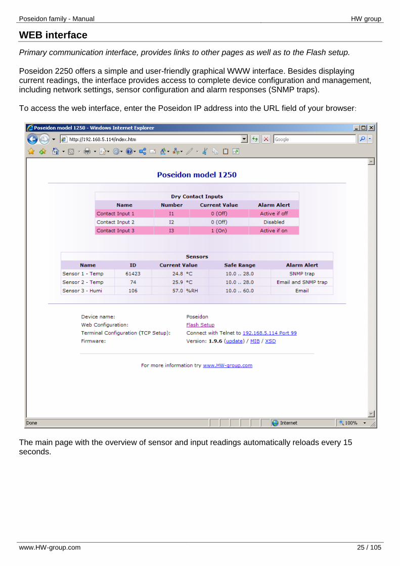
WEB interface
Primary communication interface, provides links to other pages as well as to the Flash setup. Poseidon 2250 offers a simple and user-friendly graphical WWW interface. Besides displaying current readings, the interface provides access to complete device configuration and management, including network settings, sensor configuration and alarm responses (SNMP traps). To access the web interface, enter the Poseidon IP address into the URL field of your browser:
The main page with the overview of sensor and input readings automatically reloads every 15 seconds.
Poseidon family - Manual HW group
www.HW-group.com 26 / 105
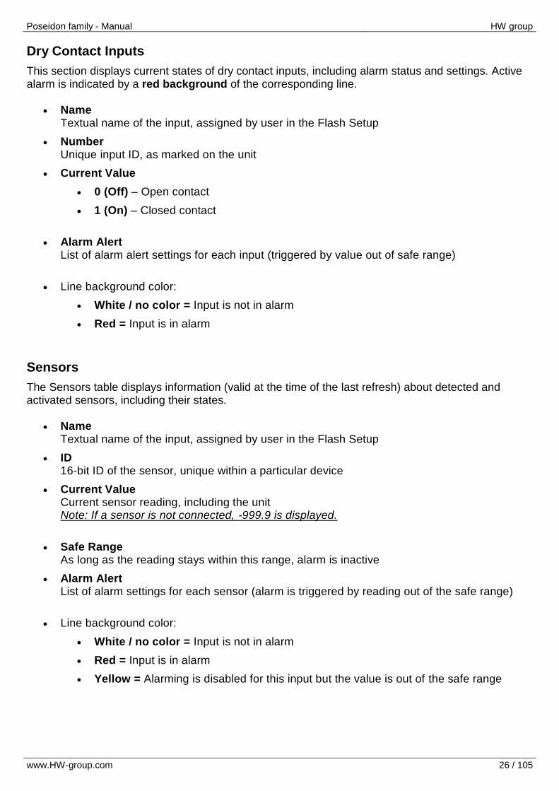
Dry Contact Inputs
This section displays current states of dry contact inputs, including alarm status and settings. Active alarm is indicated by a red background of the corresponding line.
Name Textual name of the input, assigned by user in the Flash Setup
Number Unique input ID, as marked on the unit
Current Value
0 (Off) – Open contact
1 (On) – Closed contact
Alarm Alert List of alarm alert settings for each input (triggered by value out of safe range)
Line background color:
White / no color = Input is not in alarm
Red = Input is in alarm
Sensors
The Sensors table displays information (valid at the time of the last refresh) about detected and activated sensors, including their states.
Name Textual name of the input, assigned by user in the Flash Setup
ID 16-bit ID of the sensor, unique within a particular device
Current Value Current sensor reading, including the unit Note: If a sensor is not connected, -999.9 is displayed.
Safe Range As long as the reading stays within this range, alarm is inactive
Alarm Alert List of alarm settings for each sensor (alarm is triggered by reading out of the safe range)
Line background color:
White / no color = Input is not in alarm
Red = Input is in alarm
Yellow = Alarming is disabled for this input but the value is out of the safe range
Poseidon family - Manual HW group
www.HW-group.com 27 / 105
Miscellaneous information
Device name
Device name assigned by the user in Flash Setup
Web Configuration Link to the Flash Setup
Terminal Configuration (TCP Setup) Link with the IP address and port to open a terminal session for TCP Setup
Firmware Firmware version, option to upgrade over the web (update link)
MIB links to the SNMP definition file (right-click the link and select “Save Target as…” to save the file to disk)
XSD links to the XML definition file for values.xml (right-click the link and select “Save Target as…” to save the file to disk)
Text and link “For more information try www.HW-group.com” Customizable link to the supplier or service provider. The text can be changed in TCP Setup, see the detailed description of TCP Setup.
Note: The design of the main page can be changed only after consulting the manufacturer; we offer a “Customization” program. For more information, please contact your dealer.
Poseidon family - Manual HW group
www.HW-group.com 28 / 105
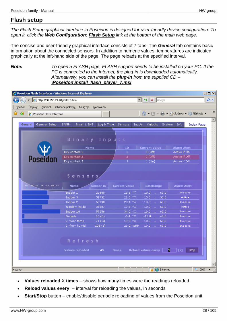
Flash setup
The Flash Setup graphical interface in Poseidon is designed for user-friendly device configuration. To open it, click the Web Configuration: Flash Setup link at the bottom of the main web page. The concise and user-friendly graphical interface consists of 7 tabs. The General tab contains basic information about the connected sensors. In addition to numeric values, temperatures are indicated graphically at the left-hand side of the page. The page reloads at the specified interval. Note: To open a FLASH page, FLASH support needs to be installed on your PC. If the
PC is connected to the Internet, the plug-in is downloaded automatically. Alternatively, you can install the plug-in from the supplied CD – \Poseidon\install_flash_player_7.msi
Values reloaded X times – shows how many times were the readings reloaded
Reload values every – interval for reloading the values, in seconds
Start/Stop button – enable/disable periodic reloading of values from the Poseidon unit
Poseidon family - Manual HW group
www.HW-group.com 29 / 105
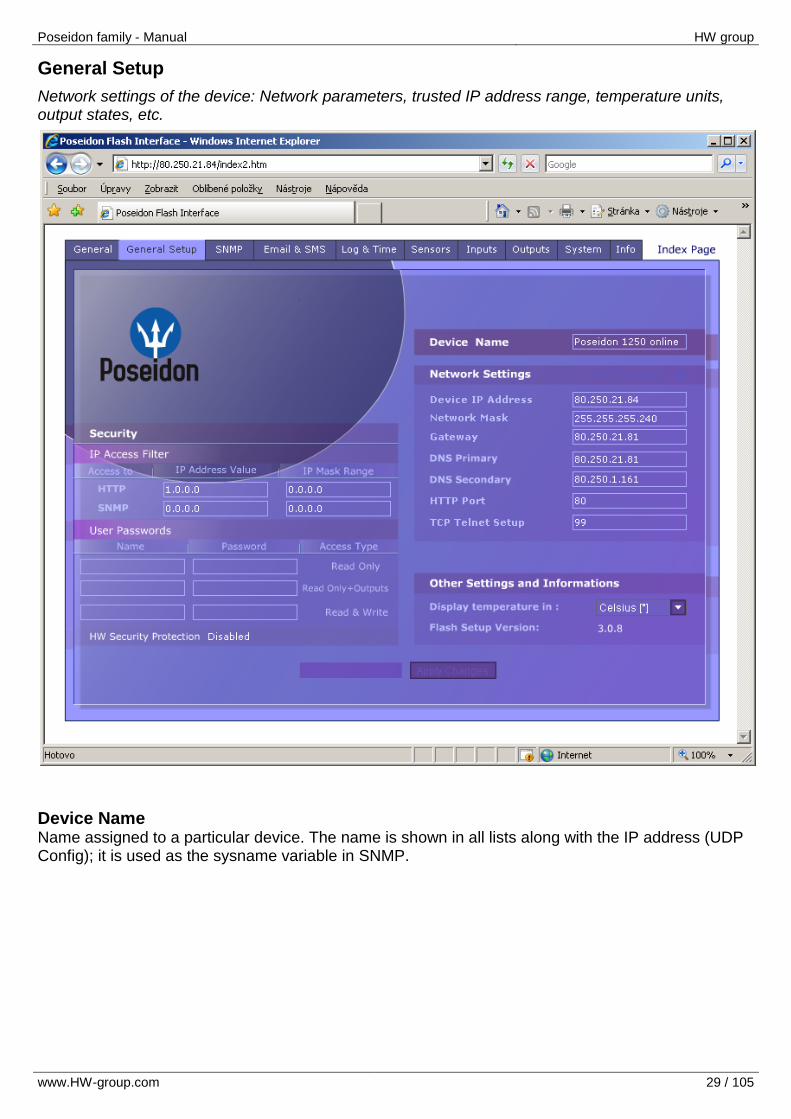
General Setup
Network settings of the device: Network parameters, trusted IP address range, temperature units, output states, etc.
Device Name Name assigned to a particular device. The name is shown in all lists along with the IP address (UDP Config); it is used as the sysname variable in SNMP.
Poseidon family - Manual HW group
www.HW-group.com 30 / 105
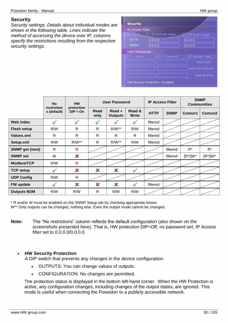
Security Security settings. Details about individual modes are shown in the following table. Lines indicate the method of accessing the device over IP, columns specify the restrictions resulting from the respective security settings.
No restrictions (default)
HW protection DIP = On
User Password IP Access Filter SNMP
Communities
Read only
Read + Outputs
Read & Write
HTTP SNMP Comun1 Comun2
Web index filtered
Flash setup R/W R R R/W** R/W filtered
Values.xml R R R R R filtered
Setup.xml R/W R/W** R R/W** R/W filtered
SNMP get (next) R R filtered R* R*
SNMP set W filtered [R*/]W* [R*/]W*
Modbus/TCP R/W R
TCP setup
UDP Config R/W R
FW update filtered
Outputs M2M R/W R/W R R/W R/W
* R and/or W must be enabled on the SNMP Setup tab by checking appropriate boxes. W** Only outputs can be changed, nothing else. Even the output mode cannot be changed.
Note: The “No restrictions” column reflects the default configuration (also shown on the screenshots presented here). That is, HW protection DIP=Off, no password set, IP Access filter set to 0.0.0.0/0.0.0.0.
HW Security Protection A DIP switch that prevents any changes in the device configuration.
OUTPUTS: You can change values of outputs.
CONFIGURATION: No changes are permitted.
The protection status is displayed in the bottom left-hand corner. When the HW Protection is active, any configuration changes, including changes of the output states, are ignored. This mode is useful when connecting the Poseidon to a publicly accessible network.
Poseidon family - Manual HW group
www.HW-group.com 31 / 105
User Passwords
Two separate user accounts (username and password) can be configured for SNMP and HTTP access.
Account types:
‘Read Only’ – can only read values and configuration settings
‘Read Only + Outputs’ – can read values and set outputs, cannot change configuration settings (not even sensor names)
‘Read & Write’ – can perform any changes
The “Read Only” account has read-only access to values, cannot perform any configuration changes. The “Read&Write” account can change configuration settings.
After setting up a username and a password, you will be asked to log in every time
you try to open the Flash interface.
Passwords also apply to access to the values.xml and setup.xml files – see the table.
In case of “Read Only” HTTP access, you will no longer be able to change configuration settings in Flash setup.
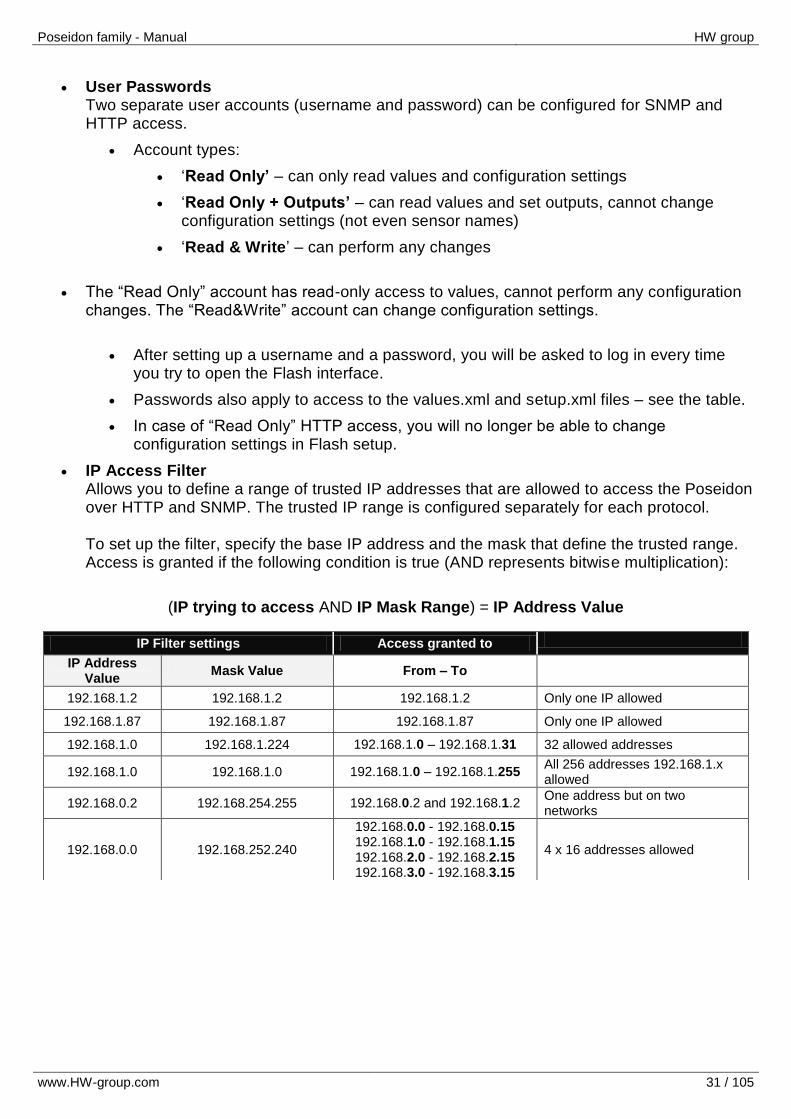
IP Access Filter Allows you to define a range of trusted IP addresses that are allowed to access the Poseidon over HTTP and SNMP. The trusted IP range is configured separately for each protocol. To set up the filter, specify the base IP address and the mask that define the trusted range. Access is granted if the following condition is true (AND represents bitwise multiplication):
(IP trying to access AND IP Mask Range) = IP Address Value
IP Filter settings Access granted to
IP Address Value
Mask Value From – To
192.168.1.2 192.168.1.2 192.168.1.2 Only one IP allowed
192.168.1.87 192.168.1.87 192.168.1.87 Only one IP allowed
192.168.1.0 192.168.1.224 192.168.1.0 – 192.168.1.31 32 allowed addresses
192.168.1.0 192.168.1.0 192.168.1.0 – 192.168.1.255 All 256 addresses 192.168.1.x allowed
192.168.0.2 192.168.254.255 192.168.0.2 and 192.168.1.2 One address but on two networks
192.168.0.0 192.168.252.240
192.168.0.0 - 192.168.0.15 192.168.1.0 - 192.168.1.15 192.168.2.0 - 192.168.2.15 192.168.3.0 - 192.168.3.15
4 x 16 addresses allowed
Poseidon family - Manual HW group
www.HW-group.com 32 / 105
SNMP Access - communities (passwords)
Two different password can be configured. For each of them, it is possible to allow R or R/W access, or temporarily disable it. Most SNMP programs use the following (default) settings. For security reasons, we highly recommend to change the R/W access password.
R (get, get next) “public”
R/W (set) “private”
Caution: SNMP Access settings are available at the SNMP Setup tab.
What to do if you forget your password
Restore the factory-default configuration of the device by one of the following methods:
Use the UDP Config utility (must run on the same network segment). Right-click the line corresponding to the device and select “Load defaults” from the pop-up menu.
Use the DIP Load defaults feature. Toggle the DIP1 switch several times during the first 5 seconds after powering up the device.
Connect to the Serial Setup (RS-232) and execute the Load Defaults function from the terminal menu. The menu is equivalent to that of Telnet Setup. To enter the menu: 9600/8N1, DIP1=1, restart the device.
Poseidon family - Manual HW group
www.HW-group.com 33 / 105
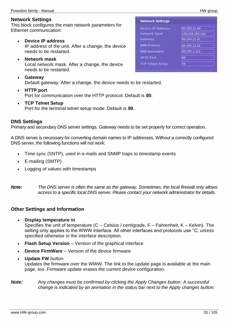
Network Settings This block configures the main network parameters for Ethernet communication:
Device IP address
IP address of the unit. After a change, the device needs to be restarted.
Network mask Local network mask. After a change, the device needs to be restarted.
Gateway Default gateway. After a change, the device needs to be restarted.
HTTP port Port for communication over the HTTP protocol. Default is 80.
TCP Telnet Setup Port for the terminal telnet setup mode. Default is 99.
DNS Settings Primary and secondary DNS server settings. Gateway needs to be set properly for correct operation.
A DNS server is necessary for converting domain names to IP addresses. Without a correctly configured DNS server, the following functions will not work:
Time sync (SNTP), used in e-mails and SNMP traps to timestamp events
E-mailing (SMTP)
Logging of values with timestamps
Note: The DNS server is often the same as the gateway. Sometimes, the local firewall only allows access to a specific local DNS server. Please contact your network administrator for details.
Other Settings and Information
Display temperature in Specifies the unit of temperature (C – Celsius / centigrade, F – Fahrenheit, K – Kelvin). The setting only applies to the WWW interface. All other interfaces and protocols use °C, unless specified otherwise in the interface description.
Flash Setup Version – Version of the graphical interface
Device FirmWare – Version of the device firmware
Update FW button Updates the firmware over the WWW. The link to the update page is available at the main page, too. Firmware update erases the current device configuration.
Note: Any changes must be confirmed by clicking the Apply Changes button. A successful
change is indicated by an animation in the status bar next to the Apply changes button.
Poseidon family - Manual HW group
www.HW-group.com 34 / 105
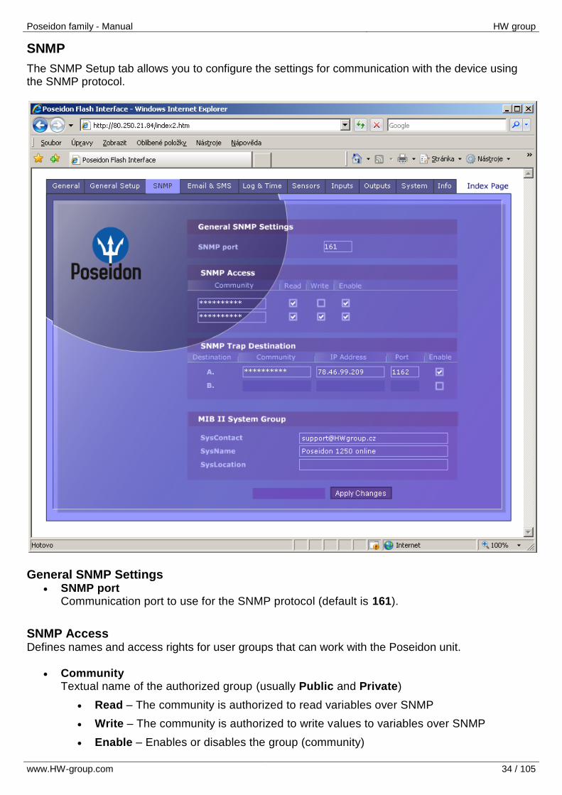
SNMP
The SNMP Setup tab allows you to configure the settings for communication with the device using the SNMP protocol.
General SNMP Settings
SNMP port Communication port to use for the SNMP protocol (default is 161).
SNMP Access Defines names and access rights for user groups that can work with the Poseidon unit.
Community Textual name of the authorized group (usually Public and Private)
Read – The community is authorized to read variables over SNMP
Write – The community is authorized to write values to variables over SNMP
Enable – Enables or disables the group (community)
Poseidon family - Manual HW group
www.HW-group.com 35 / 105
SNMP Trap Destination Define target destinations A and B for sending SNMP traps.
Community – Textual name of the group for the SNMP trap being sent
IP address – Destination address where the SNMP traps will be sent
Port – Destination port where the SNMP traps will be sent
Enable – Enables transmission of SNMP traps to this destination
MIB II System Group User-defined settings in the standard SNMP header.
SysContact – How to contact the system administrator, e.g. an e-mail address
SysName – Device name
SysLocation – Location of the unit, e.g. “IT room, floor 2”
Note: Any changes must be confirmed by clicking the Apply Changes button. A successful
change is indicated by an animation in the status bar next to the Apply changes button.
Poseidon family - Manual HW group
www.HW-group.com 36 / 105
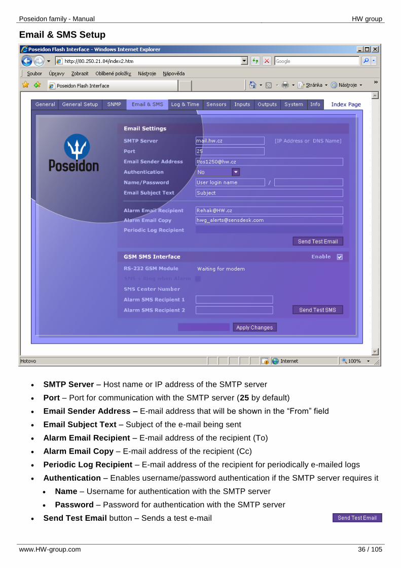
Email & SMS Setup
SMTP Server – Host name or IP address of the SMTP server
Port – Port for communication with the SMTP server (25 by default)
Email Sender Address – E-mail address that will be shown in the “From” field
Email Subject Text – Subject of the e-mail being sent
Alarm Email Recipient – E-mail address of the recipient (To)
Alarm Email Copy – E-mail address of the recipient (Cc)
Periodic Log Recipient – E-mail address of the recipient for periodically e-mailed logs
Authentication – Enables username/password authentication if the SMTP server requires it
Name – Username for authentication with the SMTP server
Password – Password for authentication with the SMTP server
Send Test Email button – Sends a test e-mail
Poseidon family - Manual HW group
www.HW-group.com 37 / 105
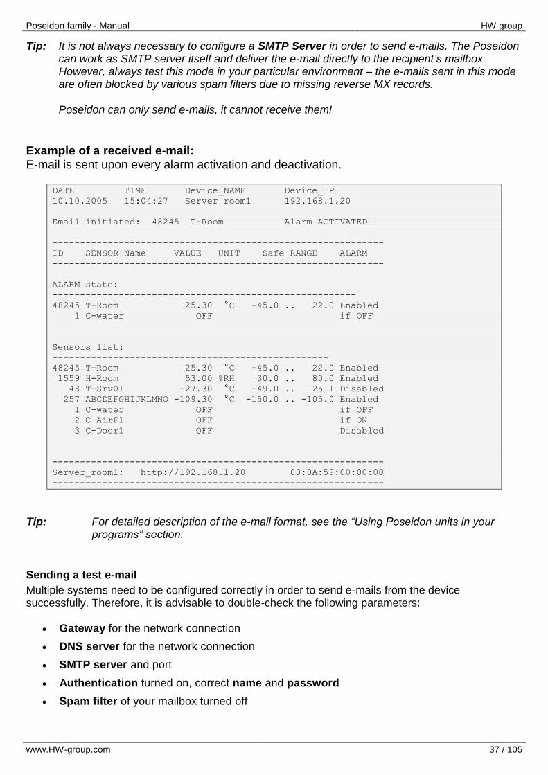
Tip: It is not always necessary to configure a SMTP Server in order to send e-mails. The Poseidon can work as SMTP server itself and deliver the e-mail directly to the recipient’s mailbox. However, always test this mode in your particular environment – the e-mails sent in this mode are often blocked by various spam filters due to missing reverse MX records. Poseidon can only send e-mails, it cannot receive them!
Example of a received e-mail: E-mail is sent upon every alarm activation and deactivation.
DATE TIME Device_NAME Device_IP
10.10.2005 15:04:27 Server_room1 192.168.1.20
Email initiated: 48245 T-Room Alarm ACTIVATED
------------------------------------------------------------
ID SENSOR_Name VALUE UNIT Safe_RANGE ALARM
------------------------------------------------------------
ALARM state:
-------------------------------------------------------
48245 T-Room 25.30 °C -45.0 .. 22.0 Enabled
1 C-water OFF if OFF
Sensors list:
--------------------------------------------------
48245 T-Room 25.30 °C -45.0 .. 22.0 Enabled
1559 H-Room 53.00 %RH 30.0 .. 80.0 Enabled
48 T-Srv01 -27.30 °C -49.0 .. –25.1 Disabled
257 ABCDEFGHIJKLMNO -109.30 °C -150.0 .. -105.0 Enabled
1 C-water OFF if OFF
2 C-AirFl OFF if ON
3 C-Door1 OFF Disabled
------------------------------------------------------------
Server_room1: http://192.168.1.20 00:0A:59:00:00:00
------------------------------------------------------------
Tip: For detailed description of the e-mail format, see the “Using Poseidon units in your
programs” section.
Sending a test e-mail
Multiple systems need to be configured correctly in order to send e-mails from the device successfully. Therefore, it is advisable to double-check the following parameters:
Gateway for the network connection
DNS server for the network connection
SMTP server and port
Authentication turned on, correct name and password
Spam filter of your mailbox turned off
Poseidon family - Manual HW group
www.HW-group.com 38 / 105
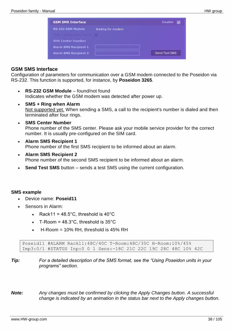
GSM SMS Interface Configuration of parameters for communication over a GSM modem connected to the Poseidon via RS-232. This function is supported, for instance, by Poseidon 3265.
RS-232 GSM Module – found/not found Indicates whether the GSM modem was detected after power up.
SMS + Ring when Alarm Not supported yet. When sending a SMS, a call to the recipient's number is dialed and then terminated after four rings.
SMS Center Number Phone number of the SMS center. Please ask your mobile service provider for the correct number. It is usually pre-configured on the SIM card.
Alarm SMS Recipient 1 Phone number of the first SMS recipient to be informed about an alarm.
Alarm SMS Recipient 2 Phone number of the second SMS recipient to be informed about an alarm.
Send Test SMS button – sends a test SMS using the current configuration.
SMS example
Device name: Poseid11
Sensors in Alarm:
Rack11 = 48.5°C, threshold is 40°C
T-Room = 48.3°C, threshold is 35°C
H-Room = 10% RH, threshold is 45% RH
Poseid11 #ALARM Rack11:48C/40C T-Room:48C/35C H-Room:10%/45%
Imp3:0/1 #STATUS Inp:0 0 1 Sens:-18C 21C 22C 19C 28C 48C 10% 42C
Tip: For a detailed description of the SMS format, see the “Using Poseidon units in your
programs” section. Note: Any changes must be confirmed by clicking the Apply Changes button. A successful
change is indicated by an animation in the status bar next to the Apply changes button.
Poseidon family - Manual HW group
www.HW-group.com 39 / 105
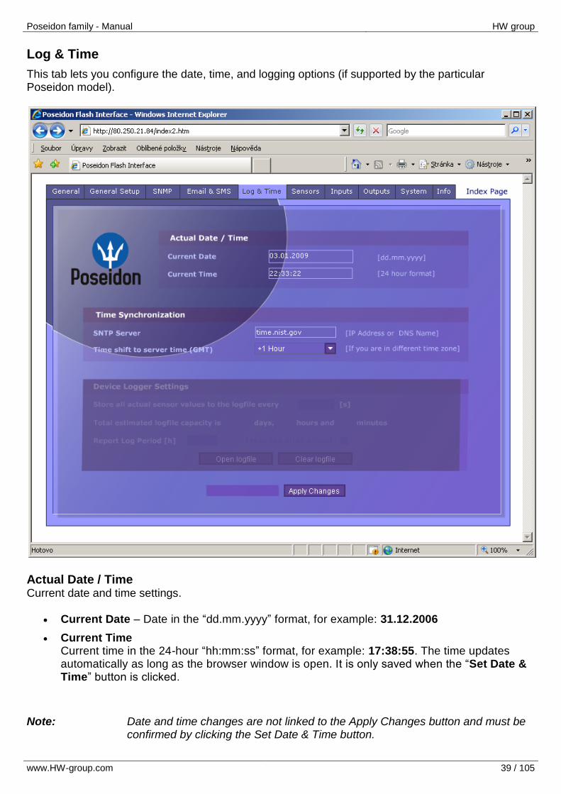
Log & Time
This tab lets you configure the date, time, and logging options (if supported by the particular Poseidon model).
Actual Date / Time Current date and time settings.
Current Date – Date in the “dd.mm.yyyy” format, for example: 31.12.2006
Current Time Current time in the 24-hour “hh:mm:ss” format, for example: 17:38:55. The time updates automatically as long as the browser window is open. It is only saved when the “Set Date & Time” button is clicked.
Note: Date and time changes are not linked to the Apply Changes button and must be
confirmed by clicking the Set Date & Time button.
Poseidon family - Manual HW group
www.HW-group.com 40 / 105
Time Synchronization
SNTP server settings for time synchronization. If the time is not set (the date 1.1.1970 is displayed), the device attempts to synchronize the time approximately once per hour until successful.
SNTP Server IP address or host name of the SNTP server to synchronize the time with. Preconfigured server is ntp1.sth.netnod.se
Time shift to server time (GMT) Configure the offset of your timezone with respect to that of the SNTP server. SNTP servers use UTC time, which is nearly equivalent to GMT (London time). Hence, for Paris, Berlin, Prague, and other locations within the same time zone, set +1 hour.
Note: The clock does not run when the device is powered off. The unit contains no
battery. After a power failure, the time will be synchronized with the SNTP server.
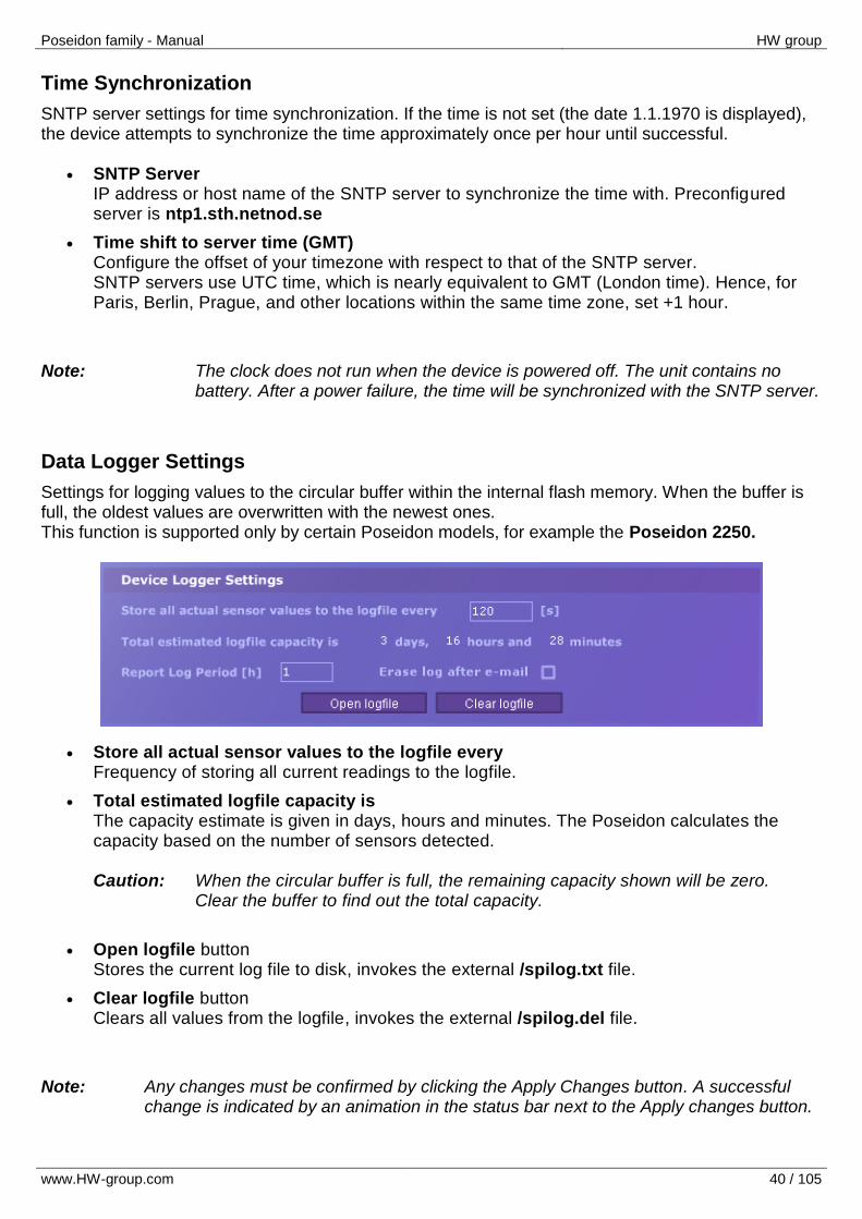
Data Logger Settings
Settings for logging values to the circular buffer within the internal flash memory. When the buffer is full, the oldest values are overwritten with the newest ones. This function is supported only by certain Poseidon models, for example the Poseidon 2250.
Store all actual sensor values to the logfile every Frequency of storing all current readings to the logfile.
Total estimated logfile capacity is The capacity estimate is given in days, hours and minutes. The Poseidon calculates the capacity based on the number of sensors detected. Caution: When the circular buffer is full, the remaining capacity shown will be zero. Clear the buffer to find out the total capacity.
Open logfile button Stores the current log file to disk, invokes the external /spilog.txt file.
Clear logfile button Clears all values from the logfile, invokes the external /spilog.del file.
Note: Any changes must be confirmed by clicking the Apply Changes button. A successful
change is indicated by an animation in the status bar next to the Apply changes button.
Poseidon family - Manual HW group
www.HW-group.com 41 / 105
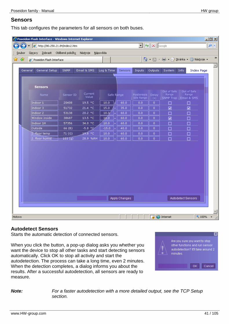
Sensors
This tab configures the parameters for all sensors on both buses.
Autodetect Sensors Starts the automatic detection of connected sensors. When you click the button, a pop-up dialog asks you whether you want the device to stop all other tasks and start detecting sensors automatically. Click OK to stop all activity and start the autodetection. The process can take a long time, even 2 minutes. When the detection completes, a dialog informs you about the results. After a successful autodetection, all sensors are ready to measure.
Note: For a faster autodetection with a more detailed output, see the TCP Setup section.
Poseidon family - Manual HW group
www.HW-group.com 42 / 105
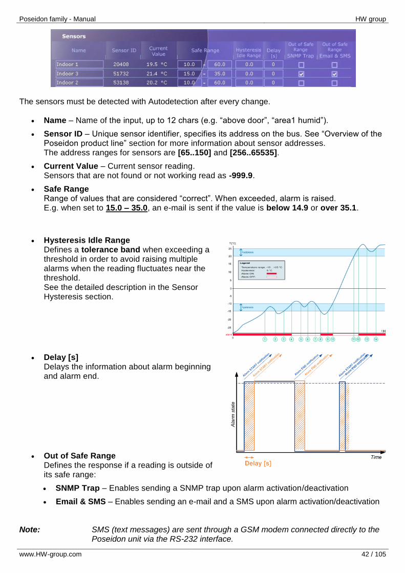
The sensors must be detected with Autodetection after every change.
Name – Name of the input, up to 12 chars (e.g. “above door”, “area1 humid”).
Sensor ID – Unique sensor identifier, specifies its address on the bus. See “Overview of the Poseidon product line” section for more information about sensor addresses. The address ranges for sensors are [65..150] and [256..65535].
Current Value – Current sensor reading. Sensors that are not found or not working read as -999.9.
Safe Range Range of values that are considered “correct”. When exceeded, alarm is raised. E.g. when set to 15.0 – 35.0, an e-mail is sent if the value is below 14.9 or over 35.1.
Hysteresis Idle Range Defines a tolerance band when exceeding a threshold in order to avoid raising multiple alarms when the reading fluctuates near the threshold. See the detailed description in the Sensor Hysteresis section.
Delay [s] Delays the information about alarm beginning and alarm end.
Out of Safe Range Defines the response if a reading is outside of its safe range:
SNMP Trap – Enables sending a SNMP trap upon alarm activation/deactivation
Email & SMS – Enables sending an e-mail and a SMS upon alarm activation/deactivation Note: SMS (text messages) are sent through a GSM modem connected directly to the
Poseidon unit via the RS-232 interface.
Poseidon family - Manual HW group
www.HW-group.com 43 / 105
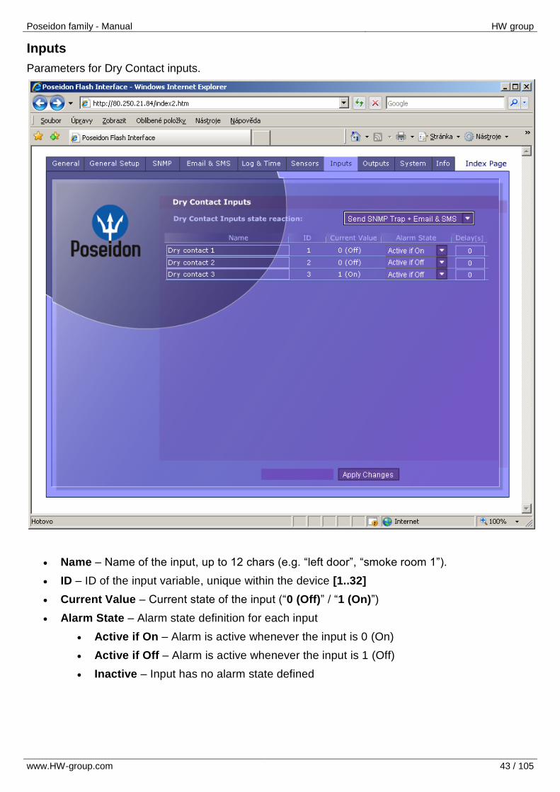
Inputs
Parameters for Dry Contact inputs.
Name – Name of the input, up to 12 chars (e.g. “left door”, “smoke room 1”).
ID – ID of the input variable, unique within the device [1..32]
Current Value – Current state of the input (“0 (Off)” / “1 (On)”)
Alarm State – Alarm state definition for each input
Active if On – Alarm is active whenever the input is 0 (On)
Active if Off – Alarm is active whenever the input is 1 (Off)
Inactive – Input has no alarm state defined
Poseidon family - Manual HW group
www.HW-group.com 44 / 105
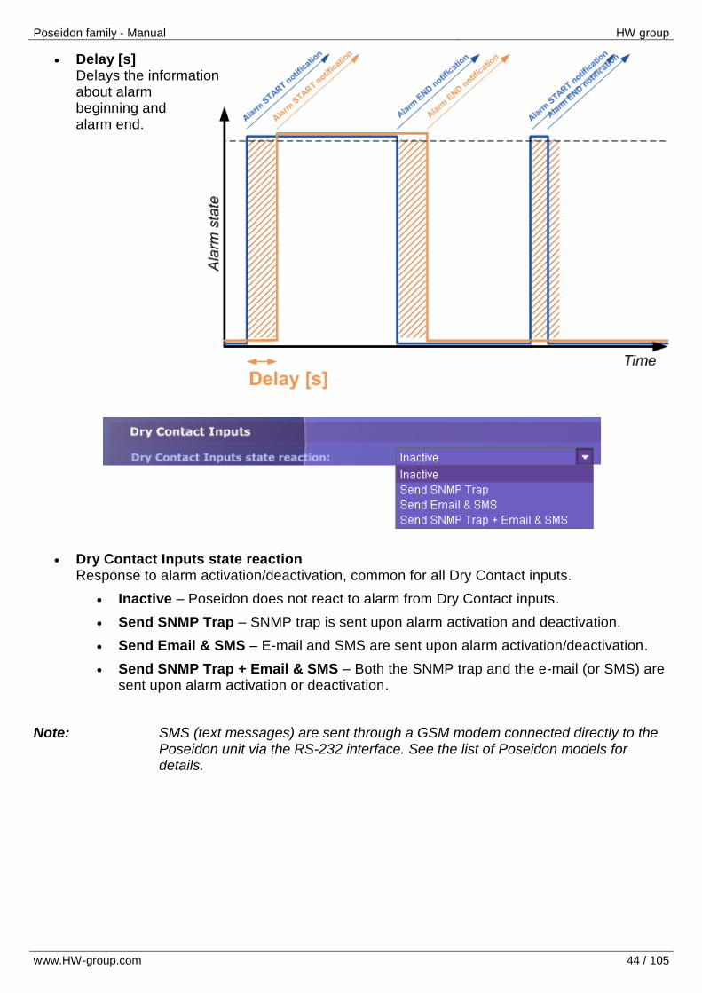
Delay [s] Delays the information about alarm beginning and alarm end.
Dry Contact Inputs state reaction Response to alarm activation/deactivation, common for all Dry Contact inputs.
Inactive – Poseidon does not react to alarm from Dry Contact inputs.
Send SNMP Trap – SNMP trap is sent upon alarm activation and deactivation.
Send Email & SMS – E-mail and SMS are sent upon alarm activation/deactivation.
Send SNMP Trap + Email & SMS – Both the SNMP trap and the e-mail (or SMS) are sent upon alarm activation or deactivation.
Note: SMS (text messages) are sent through a GSM modem connected directly to the
Poseidon unit via the RS-232 interface. See the list of Poseidon models for details.
Poseidon family - Manual HW group
www.HW-group.com 45 / 105
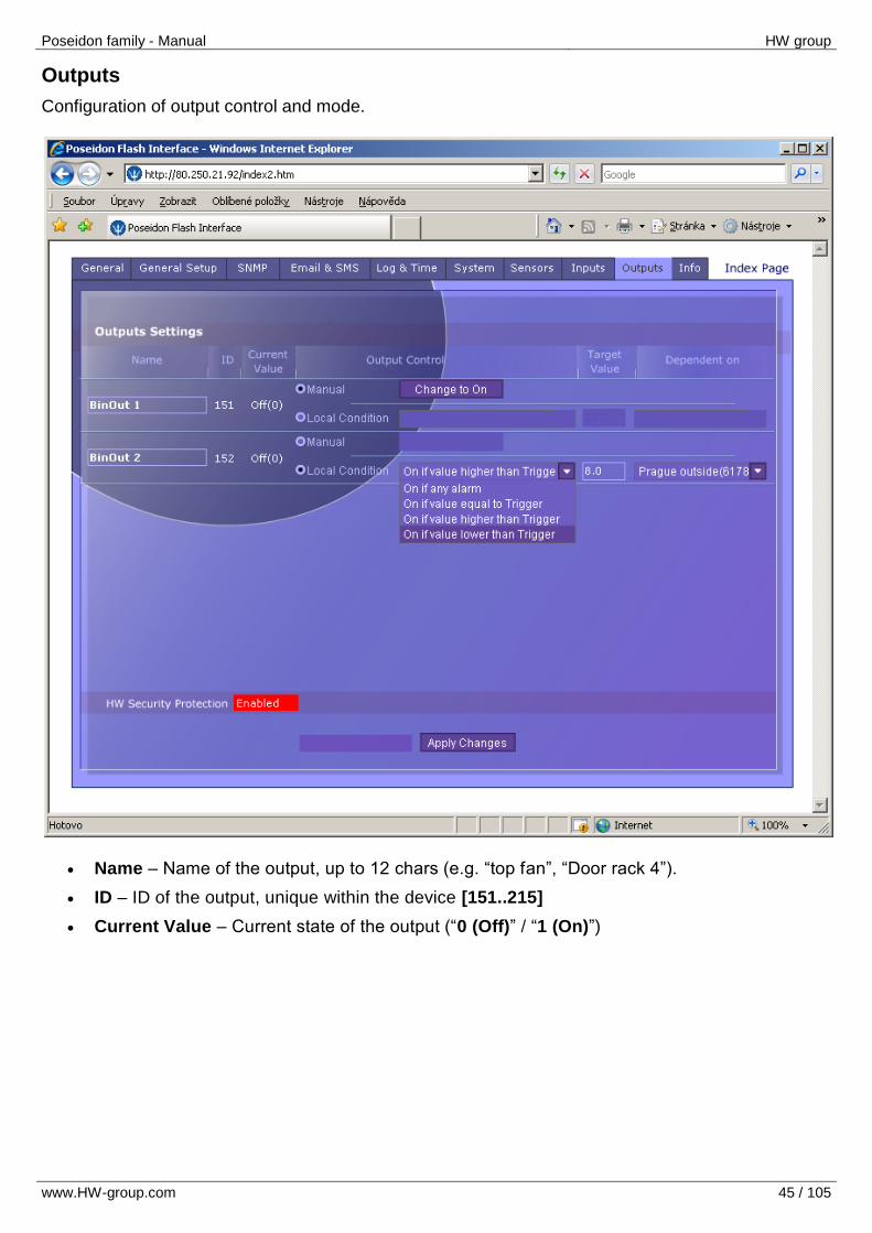
Outputs
Configuration of output control and mode.
Name – Name of the output, up to 12 chars (e.g. “top fan”, “Door rack 4”).
ID – ID of the output, unique within the device [151..215]
Current Value – Current state of the output (“0 (Off)” / “1 (On)”)
Poseidon family - Manual HW group
www.HW-group.com 46 / 105
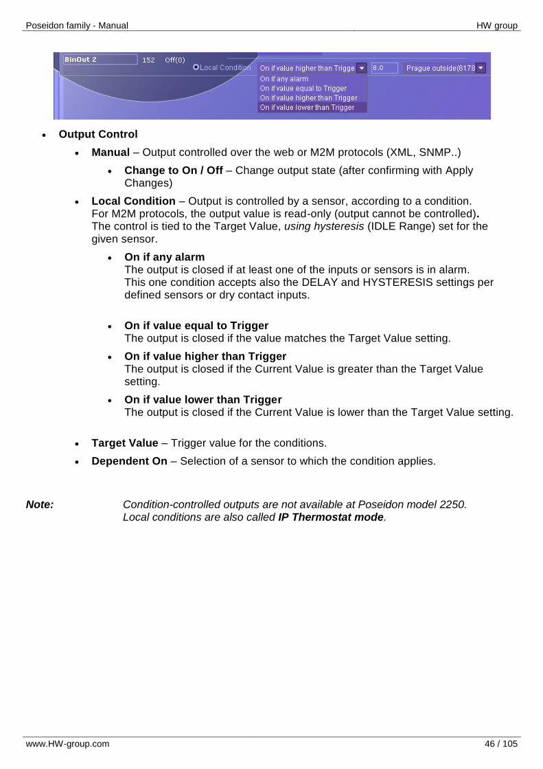
Output Control
Manual – Output controlled over the web or M2M protocols (XML, SNMP..)
Change to On / Off – Change output state (after confirming with Apply Changes)
Local Condition – Output is controlled by a sensor, according to a condition. For M2M protocols, the output value is read-only (output cannot be controlled). The control is tied to the Target Value, using hysteresis (IDLE Range) set for the given sensor.
On if any alarm The output is closed if at least one of the inputs or sensors is in alarm. This one condition accepts also the DELAY and HYSTERESIS settings per defined sensors or dry contact inputs.
On if value equal to Trigger The output is closed if the value matches the Target Value setting.
On if value higher than Trigger The output is closed if the Current Value is greater than the Target Value setting.
On if value lower than Trigger The output is closed if the Current Value is lower than the Target Value setting.
Target Value – Trigger value for the conditions.
Dependent On – Selection of a sensor to which the condition applies.
Note: Condition-controlled outputs are not available at Poseidon model 2250. Local conditions are also called IP Thermostat mode.
Poseidon family - Manual HW group
www.HW-group.com 47 / 105
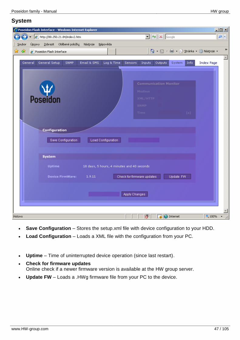
System
Save Configuration – Stores the setup.xml file with device configuration to your HDD.
Load Configuration – Loads a XML file with the configuration from your PC.
Uptime – Time of uninterrupted device operation (since last restart).
Check for firmware updates Online check if a newer firmware version is available at the HW group server.
Update FW – Loads a .HWg firmware file from your PC to the device.
Poseidon family - Manual HW group
www.HW-group.com 48 / 105
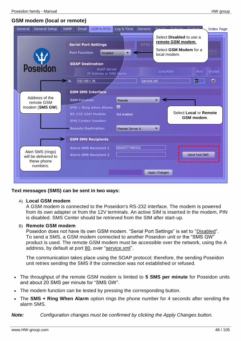
GSM modem (local or remote)
Text messages (SMS) can be sent in two ways:
A) Local GSM modem A GSM modem is connected to the Poseidon's RS-232 interface. The modem is powered from its own adapter or from the 12V terminals. An active SIM is inserted in the modem, PIN is disabled. SMS Center should be retrieved from the SIM after start-up.
B) Remote GSM modem Poseidon does not have its own GSM modem. “Serial Port Settings” is set to “Disabled”. To send a SMS, a GSM modem connected to another Poseidon unit or the “SMS GW” product is used. The remote GSM modem must be accessible over the network, using the A address, by default at port 80, over “service.xml”.
The communication takes place using the SOAP protocol; therefore, the sending Poseidon unit retries sending the SMS if the connection was not established or refused.
The throughput of the remote GSM modem is limited to 5 SMS per minute for Poseidon units and about 20 SMS per minute for “SMS GW”.
The modem function can be tested by pressing the corresponding button.
The SMS + Ring When Alarm option rings the phone number for 4 seconds after sending the alarm SMS.
Note: Configuration changes must be confirmed by clicking the Apply Changes button.
Select Local or Remote
GSM modem.
Address of the remote GSM
modem (SMS GW).
Alert SMS (rings) will be delivered to
these phone numbers.
Select Disabled to use a remote GSM modem.
Select GSM Modem for a local modem.

Poseidon family - Manual HW group
www.HW-group.com 49 / 105
Info
The Info tab displays a table with a brief comparison of all Poseidon models. The right-hand side contains a brief description of every model, its interfaces and security options.
The “Index Page” link in the upper right-hand corner quickly takes you to the main /index.html page.
Poseidon family - Manual HW group
www.HW-group.com 50 / 105
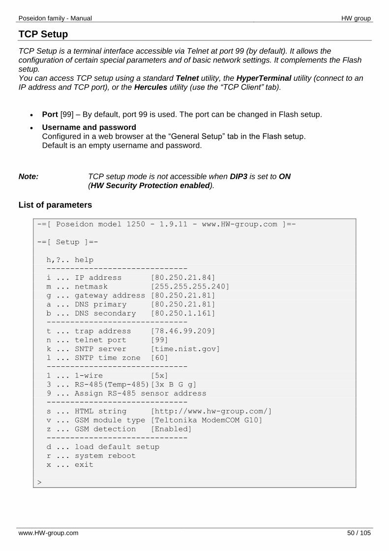
TCP Setup
TCP Setup is a terminal interface accessible via Telnet at port 99 (by default). It allows the configuration of certain special parameters and of basic network settings. It complements the Flash setup. You can access TCP setup using a standard Telnet utility, the HyperTerminal utility (connect to an IP address and TCP port), or the Hercules utility (use the “TCP Client” tab).
Port [99] – By default, port 99 is used. The port can be changed in Flash setup.
Username and password Configured in a web browser at the “General Setup” tab in the Flash setup. Default is an empty username and password.
Note: TCP setup mode is not accessible when DIP3 is set to ON (HW Security Protection enabled).
List of parameters
-=[ Poseidon model 1250 - 1.9.11 - www.HW-group.com ]=-
-=[ Setup ]=-
h,?.. help
------------------------------
i ... IP address [80.250.21.84]
m ... netmask [255.255.255.240]
g ... gateway address [80.250.21.81]
a ... DNS primary [80.250.21.81]
b ... DNS secondary [80.250.1.161]
------------------------------
t ... trap address [78.46.99.209]
n ... telnet port [99]
k ... SNTP server [time.nist.gov]
l ... SNTP time zone [60]
------------------------------
1 ... 1-wire [5x]
3 ... RS-485(Temp-485)[3x B G g]
9 ... Assign RS-485 sensor address
------------------------------
s ... HTML string [http://www.hw-group.com/]
v ... GSM module type [Teltonika ModemCOM G10]
z ... GSM detection [Enabled]
------------------------------
d ... load default setup
r ... system reboot
x ... exit
>
Poseidon family - Manual HW group
www.HW-group.com 51 / 105
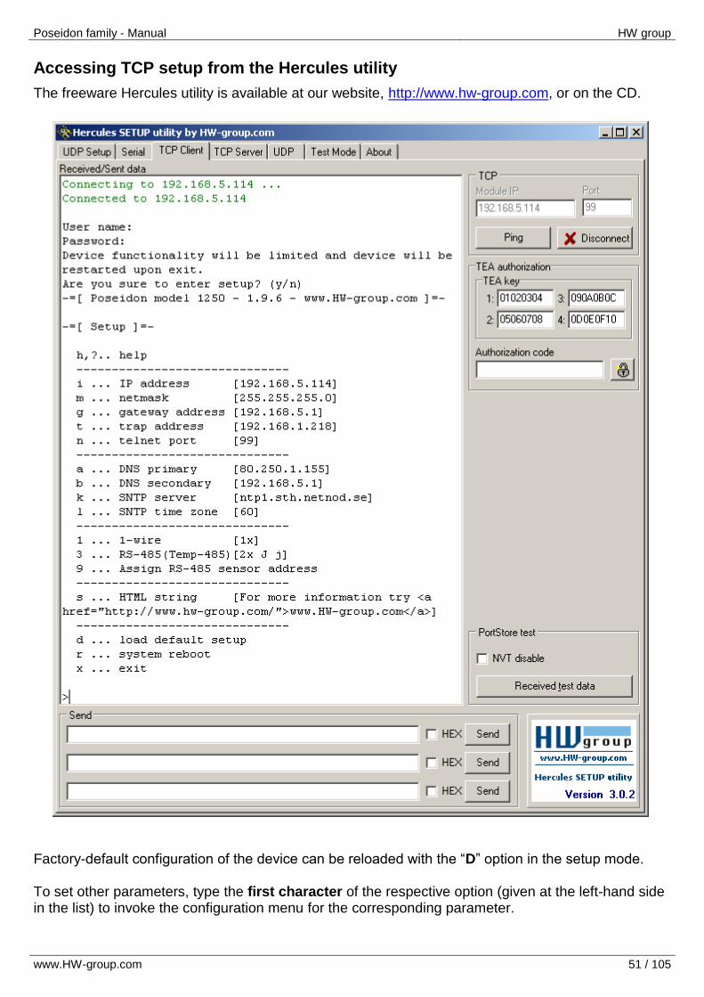
Accessing TCP setup from the Hercules utility
The freeware Hercules utility is available at our website, http://www.hw-group.com, or on the CD.
Factory-default configuration of the device can be reloaded with the “D” option in the setup mode. To set other parameters, type the first character of the respective option (given at the left-hand side in the list) to invoke the configuration menu for the corresponding parameter.
Poseidon family - Manual HW group
www.HW-group.com 52 / 105
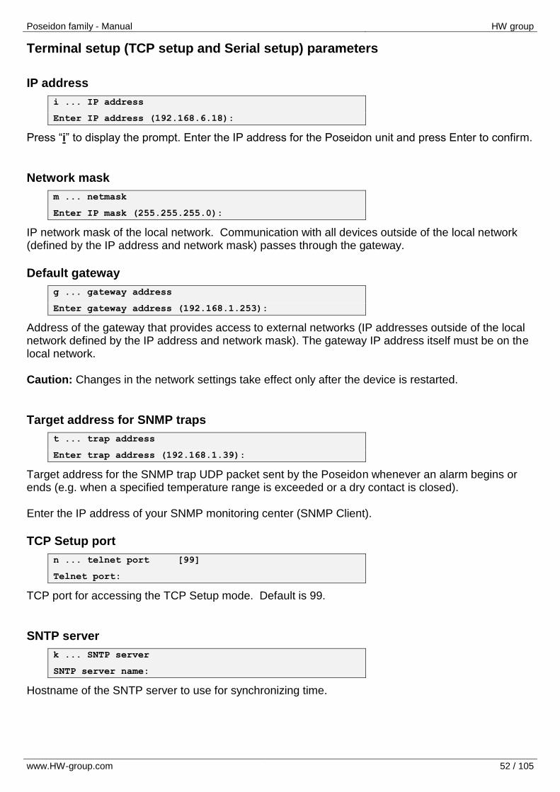
Terminal setup (TCP setup and Serial setup) parameters
IP address
i ... IP address
Enter IP address (192.168.6.18):
Press “i” to display the prompt. Enter the IP address for the Poseidon unit and press Enter to confirm.
Network mask
m ... netmask
Enter IP mask (255.255.255.0):
IP network mask of the local network. Communication with all devices outside of the local network (defined by the IP address and network mask) passes through the gateway.
Default gateway
g ... gateway address
Enter gateway address (192.168.1.253):
Address of the gateway that provides access to external networks (IP addresses outside of the local network defined by the IP address and network mask). The gateway IP address itself must be on the local network. Caution: Changes in the network settings take effect only after the device is restarted.
Target address for SNMP traps
t ... trap address
Enter trap address (192.168.1.39):
Target address for the SNMP trap UDP packet sent by the Poseidon whenever an alarm begins or ends (e.g. when a specified temperature range is exceeded or a dry contact is closed). Enter the IP address of your SNMP monitoring center (SNMP Client).
TCP Setup port
n ... telnet port [99]
Telnet port:
TCP port for accessing the TCP Setup mode. Default is 99.
SNTP server
k ... SNTP server
SNTP server name:
Hostname of the SNTP server to use for synchronizing time.
Poseidon family - Manual HW group
www.HW-group.com 53 / 105
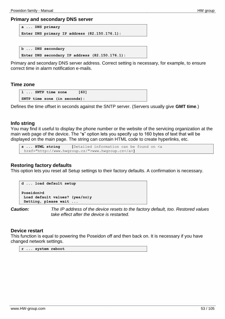
Primary and secondary DNS server
a ... DNS primary
Enter DNS primary IP address (82.150.176.1):
b ... DNS secondary
Enter DNS secondary IP address (82.150.176.1):
Primary and secondary DNS server address. Correct setting is necessary, for example, to ensure correct time in alarm notification e-mails.
Time zone
l ... SNTP time zone [60]
SNTP time zone (in seconds):
Defines the time offset in seconds against the SNTP server. (Servers usually give GMT time.)
Info string You may find it useful to display the phone number or the website of the servicing organization at the main web page of the device. The “s” option lets you specify up to 160 bytes of text that will be displayed on the main page. The string can contain HTML code to create hyperlinks, etc.
s ... HTML string [Detailed information can be found on <a
href="http://www.hwgroup.cz/">www.hwgroup.cz</a>]
Restoring factory defaults This option lets you reset all Setup settings to their factory defaults. A confirmation is necessary.
d ... load default setup
Poseidon>d Load default values? (yes/no)y Setting, please wait ...
Caution: The IP address of the device resets to the factory default, too. Restored values take effect after the device is restarted.
Device restart This function is equal to powering the Poseidon off and then back on. It is necessary if you have changed network settings.
r ... system reboot

Poseidon family - Manual HW group
www.HW-group.com 54 / 105
Exiting the Setup mode This function is equal to switching DIP1= OFF and restarting the device. However, if DIP1 remains in the ON position, the MODE LED starts blinking again to indicate operation in the RS-232 Setup mode.
x ... exit
Note: Please remember to set DIP1 to OFF after using the “x” option to exit from the RS-232
Setup mode. If you forget to set DIP1=OFF, all sensors stop working after device restart because the device enters the Setup mode again.
Poseidon family - Manual HW group
www.HW-group.com 55 / 105
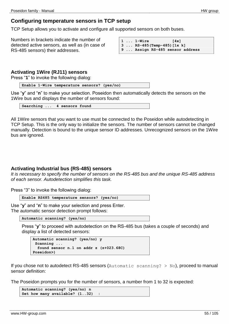
Configuring temperature sensors in TCP setup
TCP Setup allows you to activate and configure all supported sensors on both buses. Numbers in brackets indicate the number of detected active sensors, as well as (in case of RS-485 sensors) their addresses.
Activating 1Wire (RJ11) sensors Press “1” to invoke the following dialog:
Enable 1-Wire temperature sensors? (yes/no)
Use “y” and “n” to make your selection. Poseidon then automatically detects the sensors on the 1Wire bus and displays the number of sensors found:
Searching ... 4 sensors found
All 1Wire sensors that you want to use must be connected to the Poseidon while autodetecting in TCP Setup. This is the only way to initialize the sensors. The number of sensors cannot be changed manually. Detection is bound to the unique sensor ID addresses. Unrecognized sensors on the 1Wire bus are ignored.
Activating Industrial bus (RS-485) sensors It is necessary to specify the number of sensors on the RS-485 bus and the unique RS-485 address of each sensor. Autodetection simplifies this task. Press “3” to invoke the following dialog:
Enable RS485 temperature sensors? (yes/no)
Use “y” and “n” to make your selection and press Enter. The automatic sensor detection prompt follows:
Automatic scanning? (yes/no)
Press “y” to proceed with autodetection on the RS-485 bus (takes a couple of seconds) and display a list of detected sensors:
Automatic scanning? (yes/no) y Scanning ... found sensor n.1 on addr z (z+023.68C) Poseidon>)
If you chose not to autodetect RS-485 sensors (Automatic scanning? > No), proceed to manual
sensor definition: The Poseidon prompts you for the number of sensors, a number from 1 to 32 is expected:
Automatic scanning? (yes/no) n Set how many available? (1..32) :
1 ... 1-Wire [4x]
3 ... RS-485(Temp-485)[1x k]
9 ... Assign RS-485 sensor address
Poseidon family - Manual HW group
www.HW-group.com 56 / 105
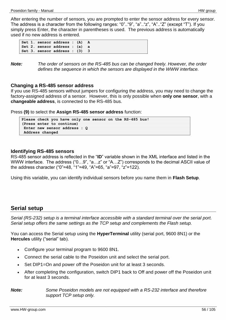
After entering the number of sensors, you are prompted to enter the sensor address for every sensor. The address is a character from the following ranges: “0”..“9”, “a”..“z”, “A”..“Z” (except “T”). If you simply press Enter, the character in parentheses is used. The previous address is automatically used if no new address is entered.
Set 1. sensor address : (A) A Set 2. sensor address : (a) a Set 3. sensor address : (3) 3
Note: The order of sensors on the RS-485 bus can be changed freely. However, the order
defines the sequence in which the sensors are displayed in the WWW interface.
Changing a RS-485 sensor address If you use RS-485 sensors without jumpers for configuring the address, you may need to change the factory-assigned address of a sensor. However, this is only possible when only one sensor, with a changeable address, is connected to the RS-485 bus. Press (9) to select the Assign RS-485 sensor address function:
Please check you have only one sensor on the RS-485 bus! (Press enter to continue) Enter new sensor address : Q Address changed
Identifying RS-485 sensors RS-485 sensor address is reflected in the “ID” variable shown in the XML interface and listed in the WWW interface. The address (“0…9”, “a…z” or “A…Z”) corresponds to the decimal ASCII value of the address character (“0”=48, “1”=49, “A”=65, “a”=97, “z”=122). Using this variable, you can identify individual sensors before you name them in Flash Setup.
Serial setup
Serial (RS-232) setup is a terminal interface accessible with a standard terminal over the serial port. Serial setup offers the same settings as the TCP setup and complements the Flash setup. You can access the Serial setup using the HyperTerminal utility (serial port, 9600 8N1) or the Hercules utility (“serial” tab).
Configure your terminal program to 9600 8N1.
Connect the serial cable to the Poseidon unit and select the serial port.
Set DIP1=On and power off the Poseidon unit for at least 3 seconds.
After completing the configuration, switch DIP1 back to Off and power off the Poseidon unit for at least 3 seconds.
Note: Some Poseidon models are not equipped with a RS-232 interface and therefore
support TCP setup only.
Poseidon family - Manual HW group
www.HW-group.com 57 / 105
Updating Firmware
Updating firmware over the Web
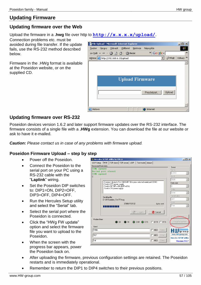
Upload the firmware in a .hwg file over http to http://x.x.x.x/upload/. Connection problems etc. must be avoided during file transfer. If the update fails, use the RS-232 method described below. Firmware in the .HWg format is available at the Poseidon website, or on the supplied CD.
Updating firmware over RS-232
Poseidon devices version 1.6.2 and later support firmware updates over the RS-232 interface. The firmware consists of a single file with a .HWg extension. You can download the file at our website or ask to have it e-mailed. Caution: Please contact us in case of any problems with firmware upload.
Poseidon Firmware Upload – step by step
Power off the Poseidon.
Connect the Poseidon to the serial port on your PC using a RS-232 cable with the “Laplink” wiring.
Set the Poseidon DIP switches to: DIP1=ON, DIP2=OFF, DIP3=OFF, DIP4=OFF.
Run the Hercules Setup utility and select the “Serial” tab.
Select the serial port where the Poseidon is connected.
Click the “HWg FW update” option and select the firmware file you want to upload to the Poseidon.
When the screen with the progress bar appears, power the Poseidon back on.
After uploading the firmware, previous configuration settings are retained. The Poseidon restarts and is immediately operational.
Remember to return the DIP1 to DIP4 switches to their previous positions.

Poseidon family - Manual HW group
www.HW-group.com 58 / 105
T-Box2 600 280
T-Box RJ11 600 356
B-Cable 600 044
Poseidon S-Hub 600 041
T-Box2 600 280
GSM Modemcom G10 600 312
Spider 600 273
12V power adapter 3pin ATX 600 079
Sensors and accessories
Accessories
Poseidon family - Manual HW group
www.HW-group.com 59 / 105
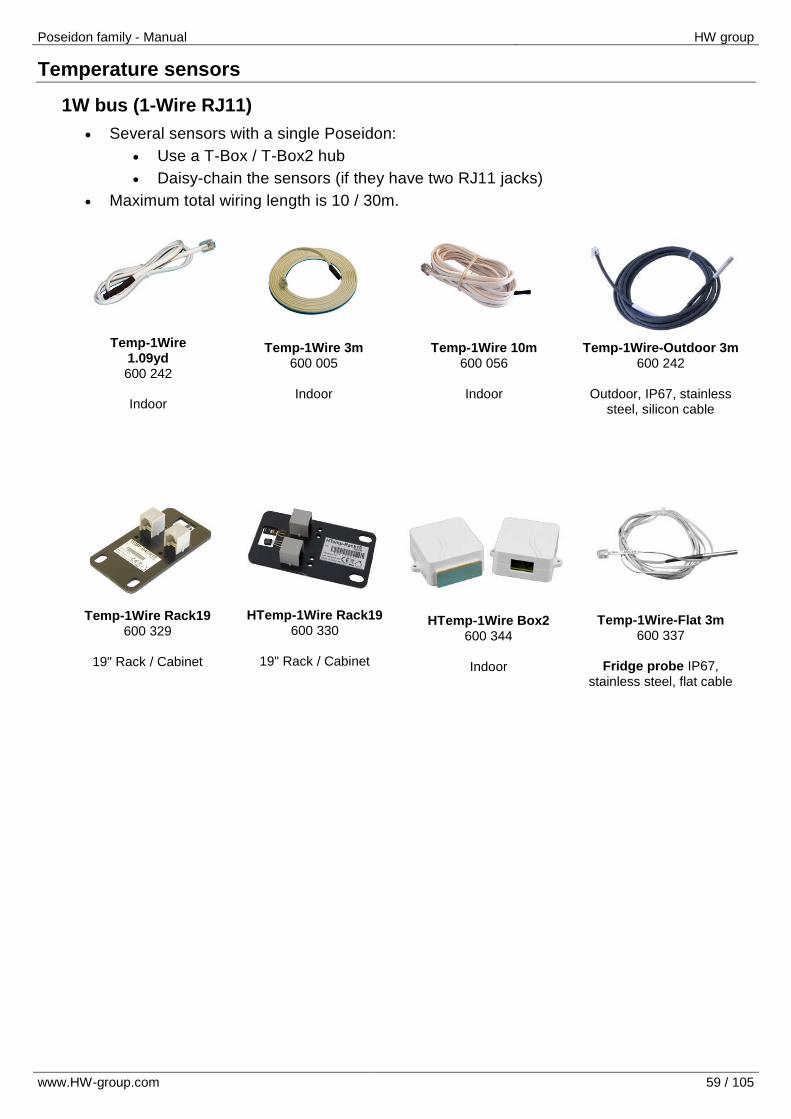
Temp-1Wire 1.09yd 600 242
Indoor
Temp-1Wire 3m 600 005
Indoor
Temp-1Wire 10m 600 056
Indoor
Temp-1Wire-Outdoor 3m 600 242
Outdoor, IP67, stainless
steel, silicon cable
Temp-1Wire Rack19 600 329
19" Rack / Cabinet
HTemp-1Wire Box2 600 344
Indoor
Temp-1Wire-Flat 3m 600 337
Fridge probe IP67,
stainless steel, flat cable
HTemp-1Wire Rack19 600 330
19" Rack / Cabinet
Temperature sensors
1W bus (1-Wire RJ11)
Several sensors with a single Poseidon:
Use a T-Box / T-Box2 hub
Daisy-chain the sensors (if they have two RJ11 jacks)
Maximum total wiring length is 10 / 30m.

Poseidon family - Manual HW group
www.HW-group.com 60 / 105
Temp-485 Box2 600 342
Indoor
Temp-485-Pt100 “DIN” 600 111
DIN rail mount converter for two external PT100 sensors
Temp-485-Pt100 “Cable” 600 114
Indoor / outdoor, can measure up to 650 °C
Temp-485-Pt100 “Frost” 600 309
For subzero temperatures
as low as -100°C
Pt30 - 2m Pt100 600 115
External Pt100 sensor, IP67,
stainless steel, 2m silicon cable
Temp-485-2xPt100 “DIN” 600 112
DIN rail mount converter for two external PT100 sensors
Temp-485-Pt100 “Head” 600 110
Head type A converter for an external PT100 sensor
Temp-485-Pt100 “Box” 600 113
Outdoor, IP67
Temp-485-Pt100 “Cable2” 600150
Boxed converter for an external PT100 sensor
HWg HTemp-485 T3411 600 368
Indoor
HWg HTemp-485 T3419 600 369
Indoor / 1m cable
HWg PHTemp-485 T7410 600 370
Indoor
Industrial bus (RS-485 RJ45)
Several sensors with a single Poseidon:
Use an S-Hub
Daisy-chain the sensors
Use the Spider converter to connect four 1Wire sensors / dry contacts
Maximum total wiring length is 1000m.
Important: A unique address on the RS-485 bus must be assigned to each sensor.
For details, see the description of individual sensors. For resolution of conflicting addresses, see the Poseidon family manual, chapter “TCP Setup”, section “Configuring temperature sensors in TCP Setup”.

Poseidon family - Manual HW group
www.HW-group.com 61 / 105
Humid-1Wire 3m 600 279
Indoor
HTemp-485 Box2 600 343
Indoor temperature
& humidity
HTemp-1Wire Rack19 600 330
19" Rack / Cabinet
HTemp-1Wire Box2 600 344
Indoor
HWg HTemp-485 T3411 600 368
Indoor
HWg HTemp-485 T3419 600 369
Indoor / 1m cable HWg PHTemp-485 T7410
600 370
Indoor
Humidity sensors
1W bus (1-Wire RJ11)
Several sensors with a single Poseidon:
Use a T-Box / T-Box2 hub
Daisy-chain the sensors (if they have two RJ11 jacks)
Maximum total wiring length is 10 / 30m.
Industrial bus (RS-485 RJ45)
Several sensors with a single Poseidon:
Use an S-Hub
Daisy-chain the sensors
Use the Spider converter to connect four 1Wire sensors / dry contacts
Maximum total wiring length is 1000m.
Important: A unique address on the RS-485 bus must be assigned to each sensor.
For details, see the description of individual sensors. For resolution of conflicting addresses, see the Poseidon family manual, chapter “TCP Setup”, section “Configuring temperature sensors in TCP Setup”.
Poseidon family - Manual HW group
www.HW-group.com 62 / 105
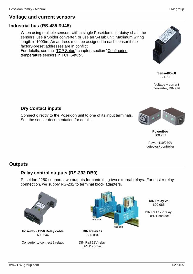
Sens-485-UI 600 116
Voltage + current converter, DIN rail
PowerEgg 600 237
Power 110/230V
detector / controller
Poseidon 1250 Relay cable 600 244
Converter to connect 2 relays
DIN Relay 2s 600 085
DIN Rail 12V relay,
DPDT contact
DIN Relay 1s 600 084
DIN Rail 12V relay,
SPTD contact
Voltage and current sensors
Industrial bus (RS-485 RJ45)
When using multiple sensors with a single Poseidon unit, daisy-chain the sensors, use a Spider converter, or use an S-Hub unit. Maximum wiring length is 1000m. An address must be assigned to each sensor if the factory-preset addresses are in conflict. For details, see the “TCP Setup” chapter, section “Configuring temperature sensors in TCP Setup”.
Dry Contact inputs
Connect directly to the Poseidon unit to one of its input terminals. See the sensor documentation for details.
Outputs
Relay control outputs (RS-232 DB9)
Poseidon 2250 supports two outputs for controlling two external relays. For easier relay connection, we supply RS-232 to terminal block adapters.
Poseidon family - Manual HW group
www.HW-group.com 63 / 105
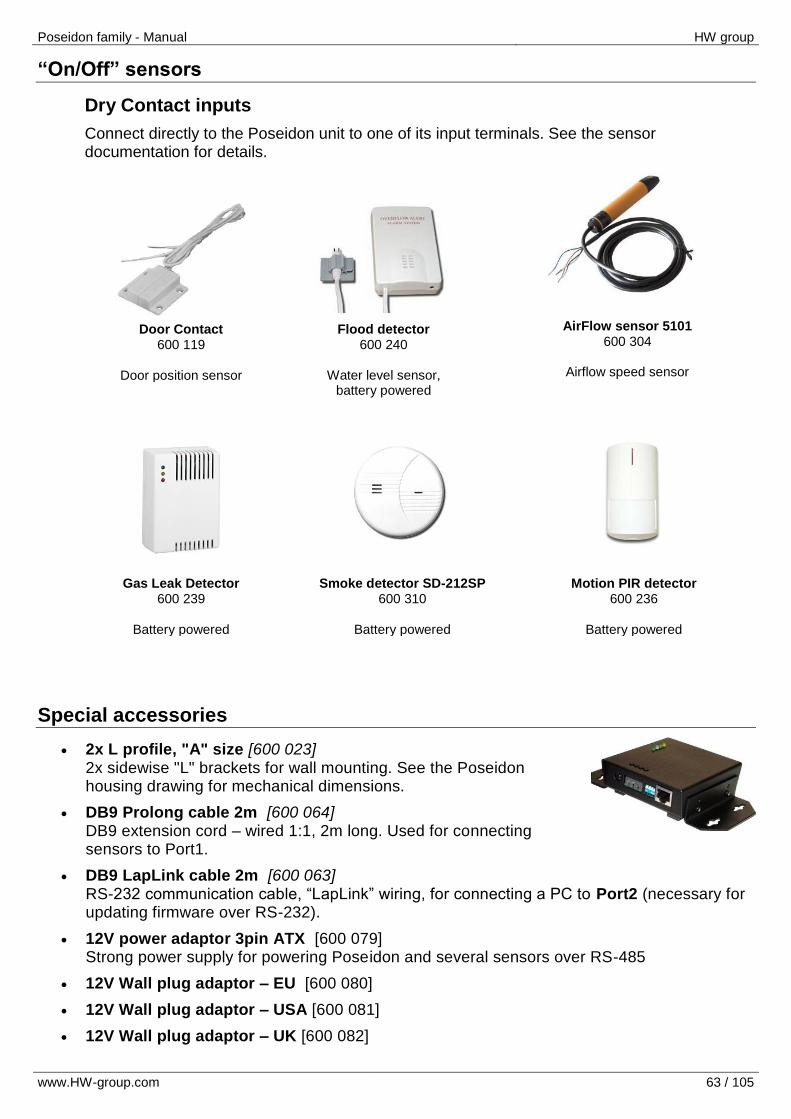
Door Contact 600 119
Door position sensor
Flood detector 600 240
Water level sensor,
battery powered
AirFlow sensor 5101 600 304
Airflow speed sensor
Gas Leak Detector 600 239
Battery powered
Smoke detector SD-212SP 600 310
Battery powered
Motion PIR detector 600 236
Battery powered
“On/Off” sensors
Dry Contact inputs
Connect directly to the Poseidon unit to one of its input terminals. See the sensor documentation for details.
Special accessories
2x L profile, "A" size [600 023] 2x sidewise "L" brackets for wall mounting. See the Poseidon housing drawing for mechanical dimensions.
DB9 Prolong cable 2m [600 064] DB9 extension cord – wired 1:1, 2m long. Used for connecting sensors to Port1.
DB9 LapLink cable 2m [600 063] RS-232 communication cable, “LapLink” wiring, for connecting a PC to Port2 (necessary for updating firmware over RS-232).
12V power adaptor 3pin ATX [600 079] Strong power supply for powering Poseidon and several sensors over RS-485
12V Wall plug adaptor – EU [600 080]
12V Wall plug adaptor – USA [600 081]
12V Wall plug adaptor – UK [600 082]
Poseidon family - Manual HW group
www.HW-group.com 64 / 105
Sample solutions and connections
Poseidon 2250 is extremely versatile. The following examples should answer most questions about what can be connected where.
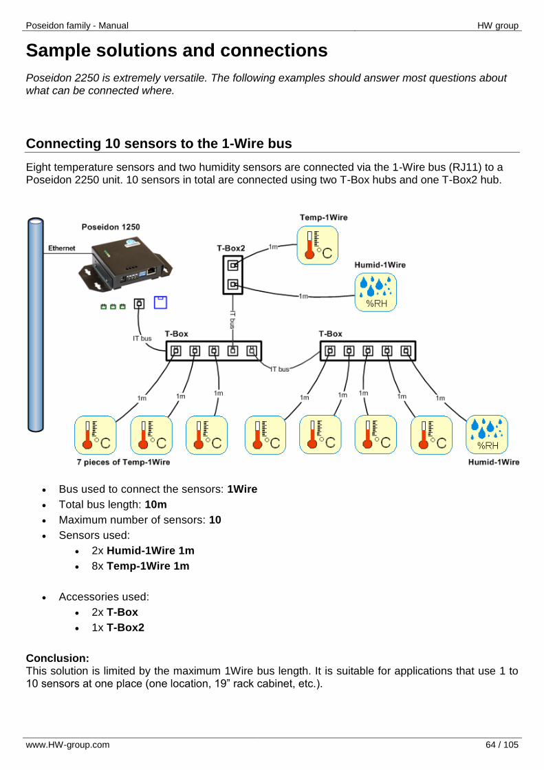
Connecting 10 sensors to the 1-Wire bus
Eight temperature sensors and two humidity sensors are connected via the 1-Wire bus (RJ11) to a Poseidon 2250 unit. 10 sensors in total are connected using two T-Box hubs and one T-Box2 hub.
Bus used to connect the sensors: 1Wire
Total bus length: 10m
Maximum number of sensors: 10
Sensors used:
2x Humid-1Wire 1m
8x Temp-1Wire 1m
Accessories used:
2x T-Box
1x T-Box2
Conclusion: This solution is limited by the maximum 1Wire bus length. It is suitable for applications that use 1 to 10 sensors at one place (one location, 19” rack cabinet, etc.).
Poseidon family - Manual HW group
www.HW-group.com 65 / 105
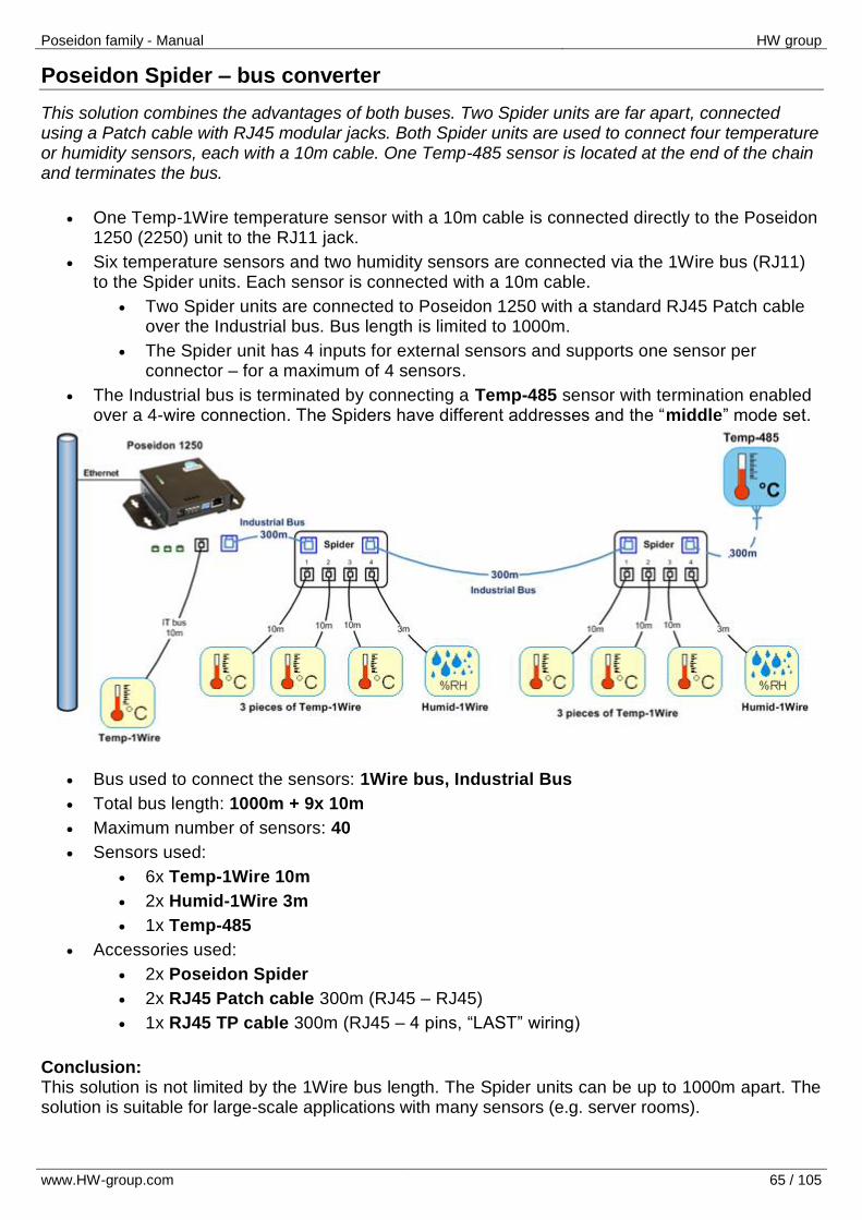
Poseidon Spider – bus converter
This solution combines the advantages of both buses. Two Spider units are far apart, connected using a Patch cable with RJ45 modular jacks. Both Spider units are used to connect four temperature or humidity sensors, each with a 10m cable. One Temp-485 sensor is located at the end of the chain and terminates the bus.
One Temp-1Wire temperature sensor with a 10m cable is connected directly to the Poseidon 1250 (2250) unit to the RJ11 jack.
Six temperature sensors and two humidity sensors are connected via the 1Wire bus (RJ11) to the Spider units. Each sensor is connected with a 10m cable.
Two Spider units are connected to Poseidon 1250 with a standard RJ45 Patch cable over the Industrial bus. Bus length is limited to 1000m.
The Spider unit has 4 inputs for external sensors and supports one sensor per connector – for a maximum of 4 sensors.
The Industrial bus is terminated by connecting a Temp-485 sensor with termination enabled over a 4-wire connection. The Spiders have different addresses and the “middle” mode set.
Bus used to connect the sensors: 1Wire bus, Industrial Bus
Total bus length: 1000m + 9x 10m
Maximum number of sensors: 40
Sensors used:
6x Temp-1Wire 10m
2x Humid-1Wire 3m
1x Temp-485
Accessories used:
2x Poseidon Spider
2x RJ45 Patch cable 300m (RJ45 – RJ45)
1x RJ45 TP cable 300m (RJ45 – 4 pins, “LAST” wiring)
Conclusion: This solution is not limited by the 1Wire bus length. The Spider units can be up to 1000m apart. The solution is suitable for large-scale applications with many sensors (e.g. server rooms).
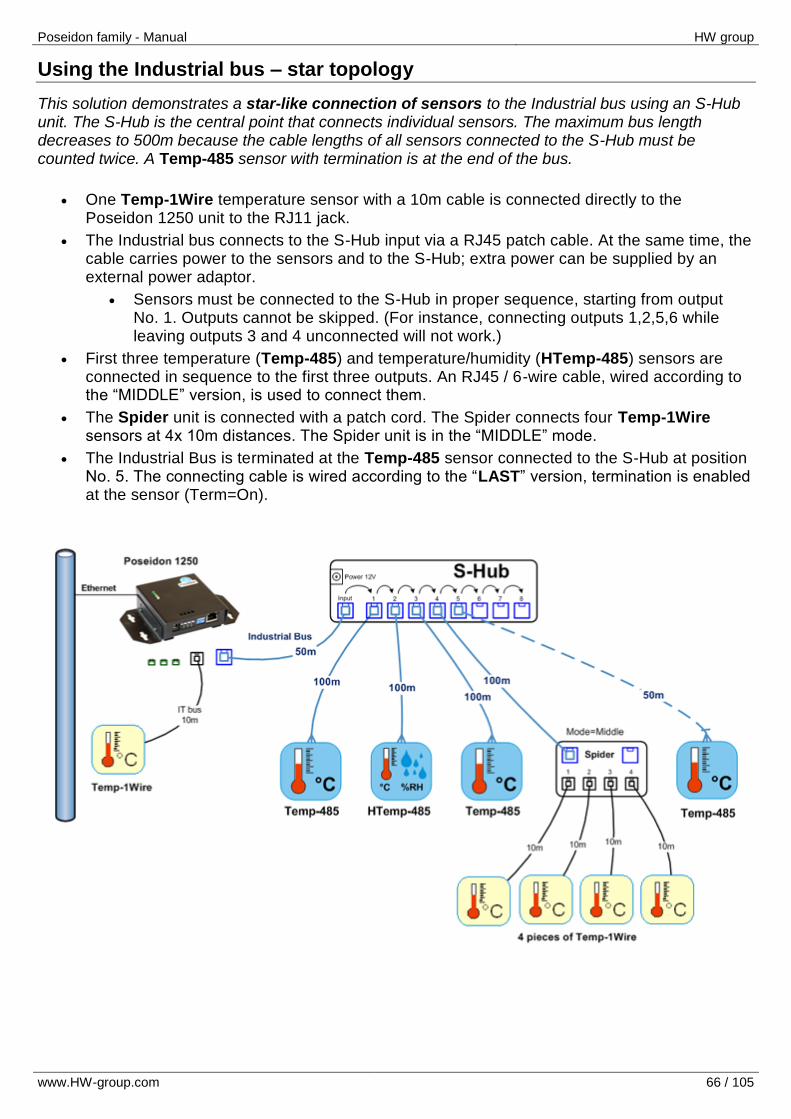
Poseidon family - Manual HW group
www.HW-group.com 66 / 105
Using the Industrial bus – star topology
This solution demonstrates a star-like connection of sensors to the Industrial bus using an S-Hub unit. The S-Hub is the central point that connects individual sensors. The maximum bus length decreases to 500m because the cable lengths of all sensors connected to the S-Hub must be counted twice. A Temp-485 sensor with termination is at the end of the bus.
One Temp-1Wire temperature sensor with a 10m cable is connected directly to the Poseidon 1250 unit to the RJ11 jack.
The Industrial bus connects to the S-Hub input via a RJ45 patch cable. At the same time, the cable carries power to the sensors and to the S-Hub; extra power can be supplied by an external power adaptor.
Sensors must be connected to the S-Hub in proper sequence, starting from output No. 1. Outputs cannot be skipped. (For instance, connecting outputs 1,2,5,6 while leaving outputs 3 and 4 unconnected will not work.)
First three temperature (Temp-485) and temperature/humidity (HTemp-485) sensors are connected in sequence to the first three outputs. An RJ45 / 6-wire cable, wired according to the “MIDDLE” version, is used to connect them.
The Spider unit is connected with a patch cord. The Spider connects four Temp-1Wire sensors at 4x 10m distances. The Spider unit is in the “MIDDLE” mode.
The Industrial Bus is terminated at the Temp-485 sensor connected to the S-Hub at position No. 5. The connecting cable is wired according to the “LAST” version, termination is enabled at the sensor (Term=On).
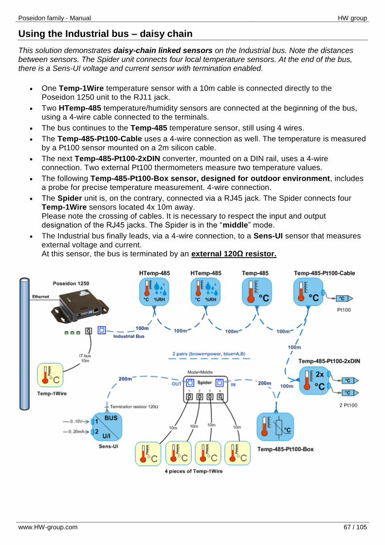
Poseidon family - Manual HW group
www.HW-group.com 67 / 105
Using the Industrial bus – daisy chain
This solution demonstrates daisy-chain linked sensors on the Industrial bus. Note the distances between sensors. The Spider unit connects four local temperature sensors. At the end of the bus, there is a Sens-UI voltage and current sensor with termination enabled.
One Temp-1Wire temperature sensor with a 10m cable is connected directly to the Poseidon 1250 unit to the RJ11 jack.
Two HTemp-485 temperature/humidity sensors are connected at the beginning of the bus, using a 4-wire cable connected to the terminals.
The bus continues to the Temp-485 temperature sensor, still using 4 wires.
The Temp-485-Pt100-Cable uses a 4-wire connection as well. The temperature is measured by a Pt100 sensor mounted on a 2m silicon cable.
The next Temp-485-Pt100-2xDIN converter, mounted on a DIN rail, uses a 4-wire connection. Two external Pt100 thermometers measure two temperature values.
The following Temp-485-Pt100-Box sensor, designed for outdoor environment, includes a probe for precise temperature measurement. 4-wire connection.
The Spider unit is, on the contrary, connected via a RJ45 jack. The Spider connects four Temp-1Wire sensors located 4x 10m away. Please note the crossing of cables. It is necessary to respect the input and output designation of the RJ45 jacks. The Spider is in the “middle” mode.
The Industrial bus finally leads, via a 4-wire connection, to a Sens-UI sensor that measures external voltage and current. At this sensor, the bus is terminated by an external 120Ω resistor.
Poseidon family - Manual HW group
www.HW-group.com 68 / 105
Software
Configuration & monitoring software
UDP setup – Freeware utility for configuring the IP addresses
PD trigger – To shutdown servers (PC) in case of power outage or overheating
Development software supports third-party SW applications
SDK – Software Development Kit with sample code for VB, .NET, Borland C, Microsoft C, Delphi
PHP logger – centralized, server-based data logging software
JAVA demo – examples of data collection and analysis using XML and SNMP in Java
VB Excel example – shows how to transfer readings to a MS Excel sheet using XML
PosDamInstWiz – Poseidon and Damocles installation wizard for third-party applications
Applications by third parties
Food & Pharmacy apps: CapTemp
IT-market-compatible SW: IBM Tivoli, HP Open View, NMS dashboard, SNMPc, LoriotPro, MRTG, CA Unicenter TNG, NetDecision
Software for security and surveillance applications: PowerCon, GisWare
SW compatible with industrial applications: FactoryLink v7.5, Wonderware InTouch
Conclusion
An up-to-date list of software products compatible with the Poseidon family is available, including details about third-party software applications and their functions, at the following website: http://www.hw-group.com/software/index_en.html
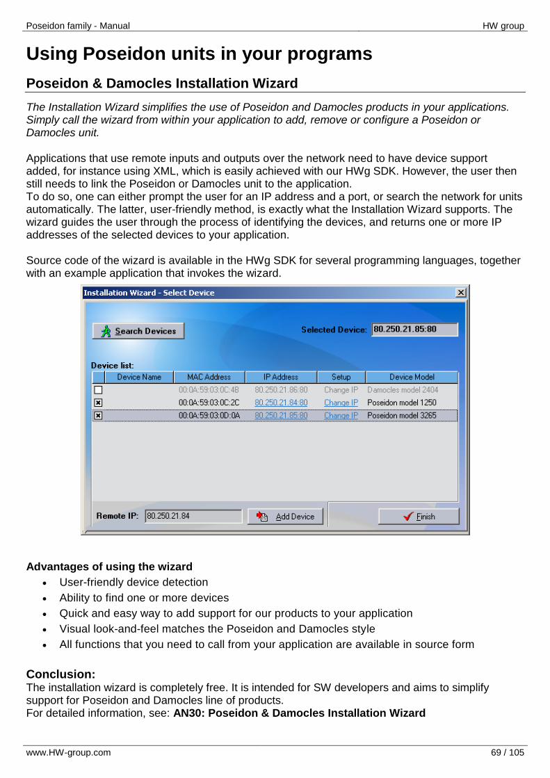
Poseidon family - Manual HW group
www.HW-group.com 69 / 105
Using Poseidon units in your programs
Poseidon & Damocles Installation Wizard
The Installation Wizard simplifies the use of Poseidon and Damocles products in your applications. Simply call the wizard from within your application to add, remove or configure a Poseidon or Damocles unit. Applications that use remote inputs and outputs over the network need to have device support added, for instance using XML, which is easily achieved with our HWg SDK. However, the user then still needs to link the Poseidon or Damocles unit to the application. To do so, one can either prompt the user for an IP address and a port, or search the network for units automatically. The latter, user-friendly method, is exactly what the Installation Wizard supports. The wizard guides the user through the process of identifying the devices, and returns one or more IP addresses of the selected devices to your application. Source code of the wizard is available in the HWg SDK for several programming languages, together with an example application that invokes the wizard. Advantages of using the wizard
User-friendly device detection
Ability to find one or more devices
Quick and easy way to add support for our products to your application
Visual look-and-feel matches the Poseidon and Damocles style
All functions that you need to call from your application are available in source form
Conclusion: The installation wizard is completely free. It is intended for SW developers and aims to simplify support for Poseidon and Damocles line of products. For detailed information, see: AN30: Poseidon & Damocles Installation Wizard
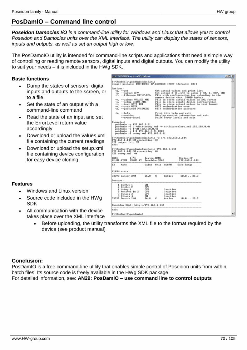
Poseidon family - Manual HW group
www.HW-group.com 70 / 105
PosDamIO – Command line control
Poseidon Damocles I/O is a command-line utility for Windows and Linux that allows you to control Poseidon and Damocles units over the XML interface. The utility can display the states of sensors, inputs and outputs, as well as set an output high or low. The PosDamoIO utility is intended for command-line scripts and applications that need a simple way of controlling or reading remote sensors, digital inputs and digital outputs. You can modify the utility to suit your needs – it is included in the HWg SDK.
Basic functions
Dump the states of sensors, digital inputs and outputs to the screen, or to a file
Set the state of an output with a command-line command
Read the state of an input and set the ErrorLevel return value accordingly
Download or upload the values.xml file containing the current readings
Download or upload the setup.xml file containing device configuration for easy device cloning
Features
Windows and Linux version
Source code included in the HWg SDK
All communication with the device takes place over the XML interface
Before uploading, the utility transforms the XML file to the format required by the device (see product manual)
Conclusion: PosDamIO is a free command-line utility that enables simple control of Poseidon units from within batch files. Its source code is freely available in the HWg SDK package. For detailed information, see: AN29: PosDamIO – use command line to control outputs

Poseidon family - Manual HW group
www.HW-group.com 71 / 105
HWg SDK
HWg SDK is a library of functions, as well as examples of their use, for Unix and Windows. The functions are intended to help third-party SW solutions communicate with our products over IP. SDK reduces the time needed to implement support for our products into your SW.
HWg SDK is free of charge; however, you need to register before downloading. After registering, you will automatically receive a link to the latest version by e-mail. http://www.hw-group.com/software/sdk/index_en.htm
HWg SDK is available in English only.
SDK installs to the Windows environment, its interface is HTML-based.
When is the SDK useful for you? For example, Poseidon products make the readings available in a well-documented XML file. A simple XML parser is sufficient to transform the data into another structure. However, to receive alarm alerts, a SNMP trap parser needs to be implemented, etc. All of these functions use standard interfaces. On the other hand, unless you already have a complete SNMP implementation in your software, it is easier to use HWg SDK functions that invoke the respective event handlers in your software. Basic SDK features
HWg SDK is simple to understand
HWg SDK speeds up the implementation of HW group products in your SW
With HWg SDK, you don’t have to worry about future changes of structures, interface updates, and so on
HWg SDK is ready to work with most programming languages
Structure according to the programming language
Visual Basic (6.0) (all 3xx examples)
Borland C++ (all 1xx examples)
Delphi (all 4xx examples)
Microsoft Visual C++ (all 2xx examples)
.NET (all 5xx examples)
other examples that do not directly use SDK functions (all 9xx examples)
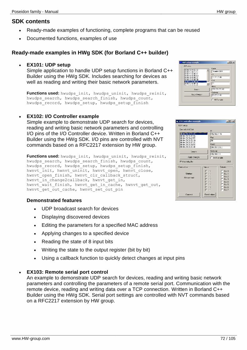
Poseidon family - Manual HW group
www.HW-group.com 72 / 105
SDK contents
Ready-made examples of functioning, complete programs that can be reused
Documented functions, examples of use
Ready-made examples in HWg SDK (for Borland C++ builder)
EX101: UDP setup Simple application to handle UDP setup functions in Borland C++ Builder using the HWg SDK. Includes searching for devices as well as reading and writing their basic network parameters. Functions used: hwudps_init, hwudps_uninit, hwudps_reinit, hwudps_search, hwudps_search_finish, hwudps_count,
hwudps_record, hwudps_setup, hwudps_setup_finish
EX102: I/O Controller example Simple example to demonstrate UDP search for devices, reading and writing basic network parameters and controlling I/O pins of the I/O Controller device. Written in Borland C++ Builder using the HWg SDK. I/O pins are controlled with NVT commands based on a RFC2217 extension by HW group. Functions used: hwudps_init, hwudps_uninit, hwudps_reinit, hwudps_search, hwudps_search_finish, hwudps_count,
hwudps_record, hwudps_setup, hwudps_setup_finish,
hwnvt_init, hwnvt_uninit, hwnvt_open, hwnvt_close,
hwnvt_open_finish, hwnvt_clr_callback_struct,
hwnvt_in_change2callback, hwnvt_get_in,
hwnvt_wait_finish, hwnvt_get_in_cache, hwnvt_get_out,
hwnvt_get_out_cache, hwnvt_set_out_pin Demonstrated features
UDP broadcast search for devices
Displaying discovered devices
Editing the parameters for a specified MAC address
Applying changes to a specified device
Reading the state of 8 input bits
Writing the state to the output register (bit by bit)
Using a callback function to quickly detect changes at input pins
EX103: Remote serial port control An example to demonstrate UDP search for devices, reading and writing basic network parameters and controlling the parameters of a remote serial port. Communication with the remote device, reading and writing data over a TCP connection. Written in Borland C++ Builder using the HWg SDK. Serial port settings are controlled with NVT commands based on a RFC2217 extension by HW group.
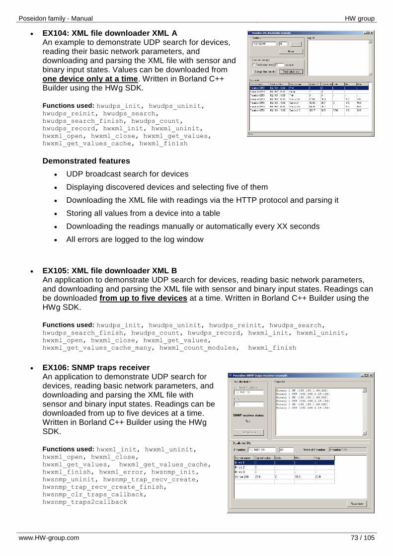
Poseidon family - Manual HW group
www.HW-group.com 73 / 105
EX104: XML file downloader XML A An example to demonstrate UDP search for devices, reading their basic network parameters, and downloading and parsing the XML file with sensor and binary input states. Values can be downloaded from one device only at a time. Written in Borland C++ Builder using the HWg SDK. Functions used: hwudps_init, hwudps_uninit, hwudps_reinit, hwudps_search,
hwudps_search_finish, hwudps_count,
hwudps_record, hwxml_init, hwxml_uninit,
hwxml_open, hwxml_close, hwxml_get_values,
hwxml_get_values_cache, hwxml_finish Demonstrated features
UDP broadcast search for devices
Displaying discovered devices and selecting five of them
Downloading the XML file with readings via the HTTP protocol and parsing it
Storing all values from a device into a table
Downloading the readings manually or automatically every XX seconds
All errors are logged to the log window
EX105: XML file downloader XML B An application to demonstrate UDP search for devices, reading basic network parameters, and downloading and parsing the XML file with sensor and binary input states. Readings can be downloaded from up to five devices at a time. Written in Borland C++ Builder using the HWg SDK. Functions used: hwudps_init, hwudps_uninit, hwudps_reinit, hwudps_search, hwudps_search_finish, hwudps_count, hwudps_record, hwxml_init, hwxml_uninit,
hwxml_open, hwxml_close, hwxml_get_values,
hwxml_get_values_cache_many, hwxml_count_modules, hwxml_finish
EX106: SNMP traps receiver An application to demonstrate UDP search for devices, reading basic network parameters, and downloading and parsing the XML file with sensor and binary input states. Readings can be downloaded from up to five devices at a time. Written in Borland C++ Builder using the HWg SDK. Functions used: hwxml_init, hwxml_uninit, hwxml_open, hwxml_close,
hwxml_get_values, hwxml_get_values_cache,
hwxml_finish, hwxml_error, hwsnmp_init,
hwsnmp_uninit, hwsnmp_trap_recv_create,
hwsnmp_trap_recv_create_finish,
hwsnmp_clr_traps_callback,
hwsnmp_traps2callback
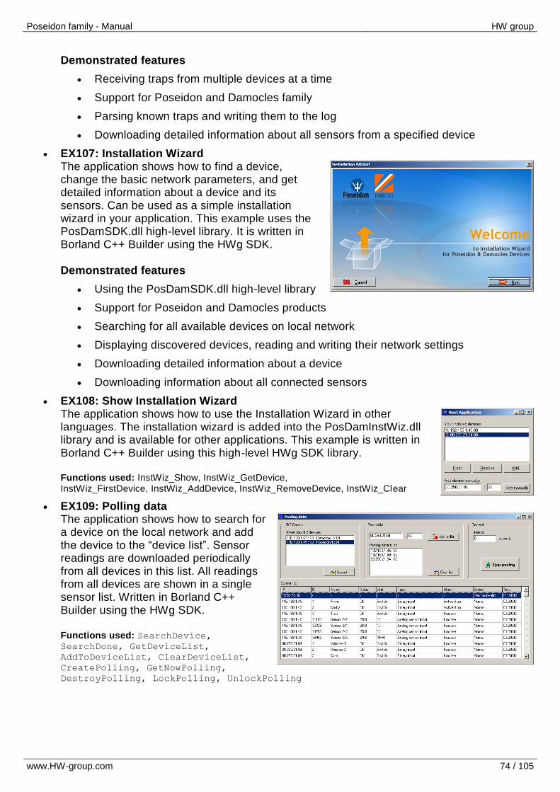
Poseidon family - Manual HW group
www.HW-group.com 74 / 105
Demonstrated features
Receiving traps from multiple devices at a time
Support for Poseidon and Damocles family
Parsing known traps and writing them to the log
Downloading detailed information about all sensors from a specified device
EX107: Installation Wizard The application shows how to find a device, change the basic network parameters, and get detailed information about a device and its sensors. Can be used as a simple installation wizard in your application. This example uses the PosDamSDK.dll high-level library. It is written in Borland C++ Builder using the HWg SDK. Demonstrated features
Using the PosDamSDK.dll high-level library
Support for Poseidon and Damocles products
Searching for all available devices on local network
Displaying discovered devices, reading and writing their network settings
Downloading detailed information about a device
Downloading information about all connected sensors
EX108: Show Installation Wizard The application shows how to use the Installation Wizard in other languages. The installation wizard is added into the PosDamInstWiz.dll library and is available for other applications. This example is written in Borland C++ Builder using this high-level HWg SDK library. Functions used: InstWiz_Show, InstWiz_GetDevice, InstWiz_FirstDevice, InstWiz_AddDevice, InstWiz_RemoveDevice, InstWiz_Clear
EX109: Polling data The application shows how to search for a device on the local network and add the device to the “device list”. Sensor readings are downloaded periodically from all devices in this list. All readings from all devices are shown in a single sensor list. Written in Borland C++ Builder using the HWg SDK. Functions used: SearchDevice, SearchDone, GetDeviceList,
AddToDeviceList, ClearDeviceList,
CreatePolling, GetNowPolling,
DestroyPolling, LockPolling, UnlockPolling
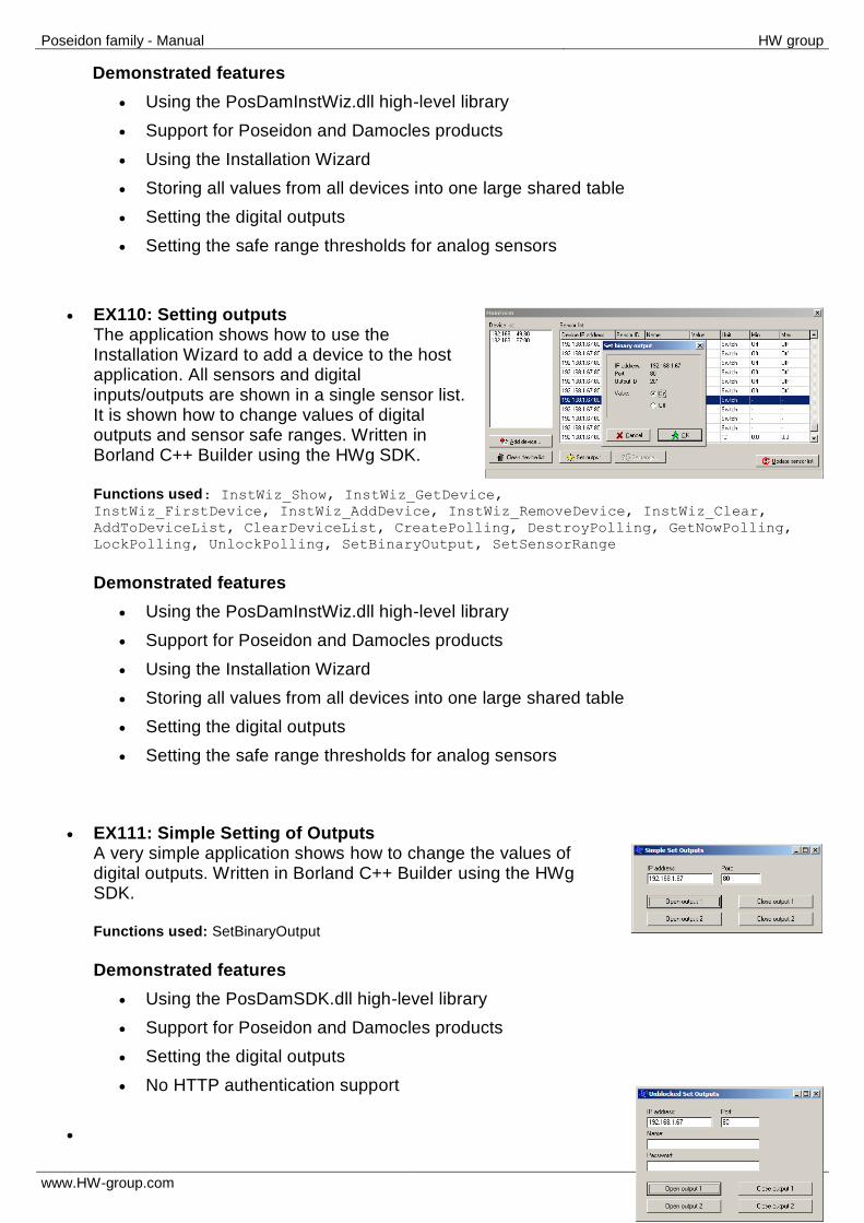
Poseidon family - Manual HW group
www.HW-group.com 75 / 105
Demonstrated features
Using the PosDamInstWiz.dll high-level library
Support for Poseidon and Damocles products
Using the Installation Wizard
Storing all values from all devices into one large shared table
Setting the digital outputs
Setting the safe range thresholds for analog sensors
EX110: Setting outputs The application shows how to use the Installation Wizard to add a device to the host application. All sensors and digital inputs/outputs are shown in a single sensor list. It is shown how to change values of digital outputs and sensor safe ranges. Written in Borland C++ Builder using the HWg SDK. Functions used: InstWiz_Show, InstWiz_GetDevice, InstWiz_FirstDevice, InstWiz_AddDevice, InstWiz_RemoveDevice, InstWiz_Clear,
AddToDeviceList, ClearDeviceList, CreatePolling, DestroyPolling, GetNowPolling,
LockPolling, UnlockPolling, SetBinaryOutput, SetSensorRange Demonstrated features
Using the PosDamInstWiz.dll high-level library
Support for Poseidon and Damocles products
Using the Installation Wizard
Storing all values from all devices into one large shared table
Setting the digital outputs
Setting the safe range thresholds for analog sensors
EX111: Simple Setting of Outputs A very simple application shows how to change the values of digital outputs. Written in Borland C++ Builder using the HWg SDK. Functions used: SetBinaryOutput Demonstrated features
Using the PosDamSDK.dll high-level library
Support for Poseidon and Damocles products
Setting the digital outputs
No HTTP authentication support
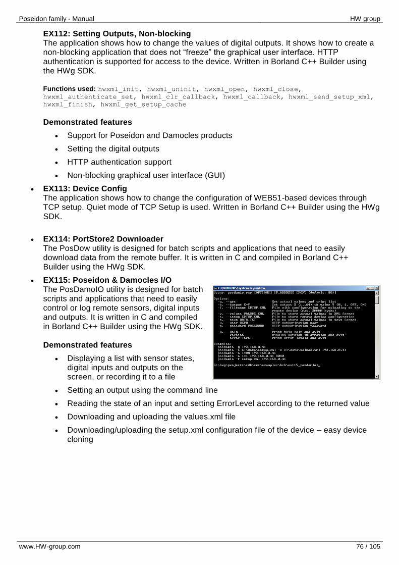
Poseidon family - Manual HW group
www.HW-group.com 76 / 105
EX112: Setting Outputs, Non-blocking The application shows how to change the values of digital outputs. It shows how to create a non-blocking application that does not “freeze” the graphical user interface. HTTP authentication is supported for access to the device. Written in Borland C++ Builder using the HWg SDK. Functions used: hwxml_init, hwxml_uninit, hwxml_open, hwxml_close, hwxml_authenticate_set, hwxml_clr_callback, hwxml_callback, hwxml_send_setup_xml,
hwxml_finish, hwxml_get_setup_cache Demonstrated features
Support for Poseidon and Damocles products
Setting the digital outputs
HTTP authentication support
Non-blocking graphical user interface (GUI)
EX113: Device Config The application shows how to change the configuration of WEB51-based devices through TCP setup. Quiet mode of TCP Setup is used. Written in Borland C++ Builder using the HWg SDK.
EX114: PortStore2 Downloader The PosDow utility is designed for batch scripts and applications that need to easily download data from the remote buffer. It is written in C and compiled in Borland C++ Builder using the HWg SDK.
EX115: Poseidon & Damocles I/O The PosDamoIO utility is designed for batch scripts and applications that need to easily control or log remote sensors, digital inputs and outputs. It is written in C and compiled in Borland C++ Builder using the HWg SDK. Demonstrated features
Displaying a list with sensor states, digital inputs and outputs on the screen, or recording it to a file
Setting an output using the command line
Reading the state of an input and setting ErrorLevel according to the returned value
Downloading and uploading the values.xml file
Downloading/uploading the setup.xml configuration file of the device – easy device cloning
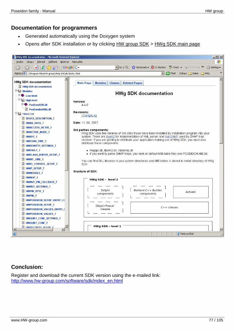
Poseidon family - Manual HW group
www.HW-group.com 77 / 105
Documentation for programmers
Generated automatically using the Doxygen system
Opens after SDK installation or by clicking HW group SDK > HWg SDK main page
Conclusion:
Register and download the current SDK version using the e-mailed link: http://www.hw-group.com/software/sdk/index_en.html
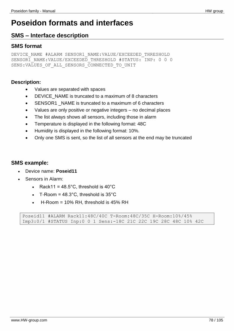
Poseidon family - Manual HW group
www.HW-group.com 78 / 105
Poseidon formats and interfaces
SMS – Interface description
SMS format
DEVICE_NAME #ALARM SENSOR1_NAME:VALUE/EXCEEDED_THRESHOLD
SENSOR1_NAME:VALUE/EXCEEDED_THRESHOLD #STATUS: INP: 0 0 0
SENS:VALUES_OF_ALL_SENSORS_CONNECTED_TO_UNIT
Description:
Values are separated with spaces
DEVICE_NAME is truncated to a maximum of 8 characters
SENSOR1 _NAME is truncated to a maximum of 6 characters
Values are only positive or negative integers – no decimal places
The list always shows all sensors, including those in alarm
Temperature is displayed in the following format: 48C
Humidity is displayed in the following format: 10%.
Only one SMS is sent, so the list of all sensors at the end may be truncated
SMS example:
Device name: Poseid11
Sensors in Alarm:
Rack11 = 48.5°C, threshold is 40°C
T-Room = 48.3°C, threshold is 35°C
H-Room = 10% RH, threshold is 45% RH
Poseid11 #ALARM Rack11:48C/40C T-Room:48C/35C H-Room:10%/45%
Imp3:0/1 #STATUS Inp:0 0 1 Sens:-18C 21C 22C 19C 28C 48C 10% 42C
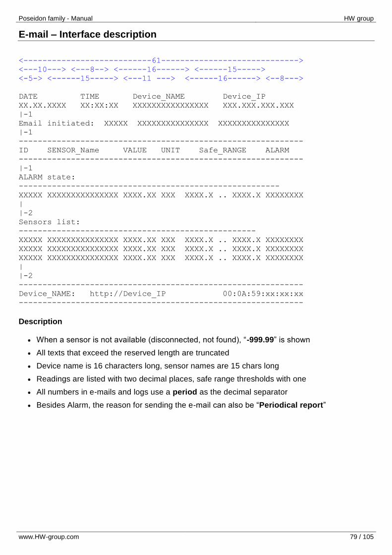
Poseidon family - Manual HW group
www.HW-group.com 79 / 105
E-mail – Interface description
<---------------------------61----------------------------->
<---10---> <---8--> <------16------> <------15----->
<-5-> <------15-----> <---11 ---> <------16------> <--8--->
DATE TIME Device_NAME Device_IP
XX.XX.XXXX XX:XX:XX XXXXXXXXXXXXXXXX XXX.XXX.XXX.XXX
|-1
Email initiated: XXXXX XXXXXXXXXXXXXXX XXXXXXXXXXXXXXX
|-1
------------------------------------------------------------
ID SENSOR_Name VALUE UNIT Safe_RANGE ALARM
------------------------------------------------------------
|-1
ALARM state:
-------------------------------------------------------
XXXXX XXXXXXXXXXXXXXX XXXX.XX XXX XXXX.X .. XXXX.X XXXXXXXX
|
|-2
Sensors list:
--------------------------------------------------
XXXXX XXXXXXXXXXXXXXX XXXX.XX XXX XXXX.X .. XXXX.X XXXXXXXX
XXXXX XXXXXXXXXXXXXXX XXXX.XX XXX XXXX.X .. XXXX.X XXXXXXXX
XXXXX XXXXXXXXXXXXXXX XXXX.XX XXX XXXX.X .. XXXX.X XXXXXXXX
|
|-2
------------------------------------------------------------
Device_NAME: http://Device_IP 00:0A:59:xx:xx:xx
------------------------------------------------------------
Description
When a sensor is not available (disconnected, not found), “-999.99” is shown
All texts that exceed the reserved length are truncated
Device name is 16 characters long, sensor names are 15 chars long
Readings are listed with two decimal places, safe range thresholds with one
All numbers in e-mails and logs use a period as the decimal separator
Besides Alarm, the reason for sending the e-mail can also be “Periodical report”
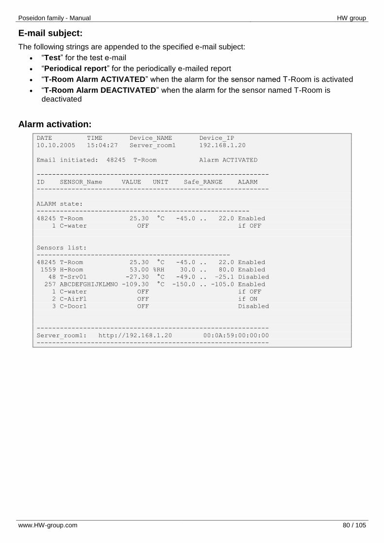
Poseidon family - Manual HW group
www.HW-group.com 80 / 105
E-mail subject:
The following strings are appended to the specified e-mail subject:
“Test” for the test e-mail
“Periodical report” for the periodically e-mailed report
“T-Room Alarm ACTIVATED” when the alarm for the sensor named T-Room is activated
“T-Room Alarm DEACTIVATED” when the alarm for the sensor named T-Room is deactivated
Alarm activation:
DATE TIME Device_NAME Device_IP
10.10.2005 15:04:27 Server_room1 192.168.1.20
Email initiated: 48245 T-Room Alarm ACTIVATED
------------------------------------------------------------
ID SENSOR_Name VALUE UNIT Safe_RANGE ALARM
------------------------------------------------------------
ALARM state:
-------------------------------------------------------
48245 T-Room 25.30 °C -45.0 .. 22.0 Enabled
1 C-water OFF if OFF
Sensors list:
--------------------------------------------------
48245 T-Room 25.30 °C -45.0 .. 22.0 Enabled
1559 H-Room 53.00 %RH 30.0 .. 80.0 Enabled
48 T-Srv01 -27.30 °C -49.0 .. –25.1 Disabled
257 ABCDEFGHIJKLMNO -109.30 °C -150.0 .. -105.0 Enabled
1 C-water OFF if OFF
2 C-AirFl OFF if ON
3 C-Door1 OFF Disabled
------------------------------------------------------------
Server_room1: http://192.168.1.20 00:0A:59:00:00:00
------------------------------------------------------------
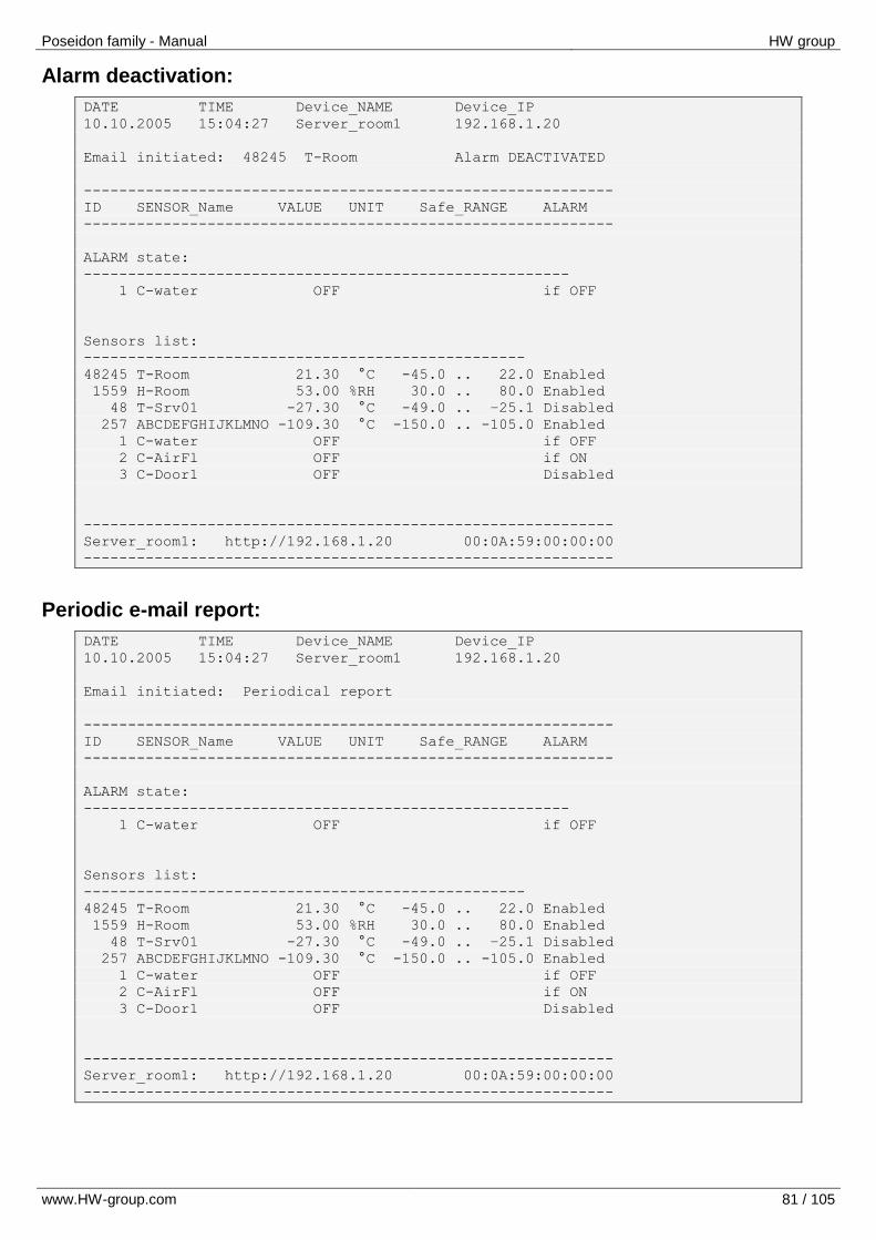
Poseidon family - Manual HW group
www.HW-group.com 81 / 105
Alarm deactivation:
DATE TIME Device_NAME Device_IP
10.10.2005 15:04:27 Server_room1 192.168.1.20
Email initiated: 48245 T-Room Alarm DEACTIVATED
------------------------------------------------------------
ID SENSOR_Name VALUE UNIT Safe_RANGE ALARM
------------------------------------------------------------
ALARM state:
-------------------------------------------------------
1 C-water OFF if OFF
Sensors list:
--------------------------------------------------
48245 T-Room 21.30 °C -45.0 .. 22.0 Enabled
1559 H-Room 53.00 %RH 30.0 .. 80.0 Enabled
48 T-Srv01 -27.30 °C -49.0 .. –25.1 Disabled
257 ABCDEFGHIJKLMNO -109.30 °C -150.0 .. -105.0 Enabled
1 C-water OFF if OFF
2 C-AirFl OFF if ON
3 C-Door1 OFF Disabled
------------------------------------------------------------
Server_room1: http://192.168.1.20 00:0A:59:00:00:00
------------------------------------------------------------
Periodic e-mail report:
DATE TIME Device_NAME Device_IP
10.10.2005 15:04:27 Server_room1 192.168.1.20
Email initiated: Periodical report
------------------------------------------------------------
ID SENSOR_Name VALUE UNIT Safe_RANGE ALARM
------------------------------------------------------------
ALARM state:
-------------------------------------------------------
1 C-water OFF if OFF
Sensors list:
--------------------------------------------------
48245 T-Room 21.30 °C -45.0 .. 22.0 Enabled
1559 H-Room 53.00 %RH 30.0 .. 80.0 Enabled
48 T-Srv01 -27.30 °C -49.0 .. –25.1 Disabled
257 ABCDEFGHIJKLMNO -109.30 °C -150.0 .. -105.0 Enabled
1 C-water OFF if OFF
2 C-AirFl OFF if ON
3 C-Door1 OFF Disabled
------------------------------------------------------------
Server_room1: http://192.168.1.20 00:0A:59:00:00:00
------------------------------------------------------------
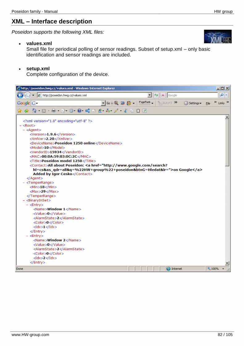
Poseidon family - Manual HW group
www.HW-group.com 82 / 105
XML – Interface description
Poseidon supports the following XML files:
values.xml Small file for periodical polling of sensor readings. Subset of setup.xml – only basic identification and sensor readings are included.
setup.xml Complete configuration of the device.
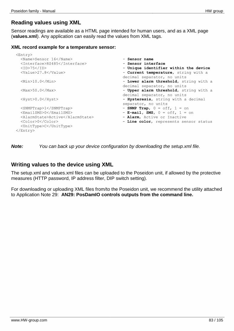
Poseidon family - Manual HW group
www.HW-group.com 83 / 105
Reading values using XML
Sensor readings are available as a HTML page intended for human users, and as a XML page (values.xml). Any application can easily read the values from XML tags. XML record example for a temperature sensor:
<Entry>
<Name>Sensor 16</Name> - Sensor name
<Interface>RS485</Interface> - Sensor interface
<ID>75</ID> - Unique identifier within the device
<Value>27.8</Value> - Current temperature, string with a
decimal separator, no units
<Min>10.0</Min> - Lower alarm threshold, string with a
decimal separator, no units
<Max>50.0</Max> - Upper alarm threshold, string with a
decimal separator, no units
<Hyst>0.0</Hyst> - Hysteresis, string with a decimal
separator, no units
<SNMPTrap>1</SNMPTrap> - SNMP Trap, 0 = off, 1 = on
<EmailSMS>0</EmailSMS> - E-mail, SMS, 0 = off, 1 = on
<AlarmState>Active</AlarmState> - Alarm, Active or Inactive
<Color>0</Color> - Line color, represents sensor status
<UnitType>C</UnitType>
</Entry>
Note: You can back up your device configuration by downloading the setup.xml file.
Writing values to the device using XML
The setup.xml and values.xml files can be uploaded to the Poseidon unit, if allowed by the protective measures (HTTP password, IP address filter, DIP switch setting). For downloading or uploading XML files from/to the Poseidon unit, we recommend the utility attached to Application Note 29: AN29: PosDamIO controls outputs from the command line.
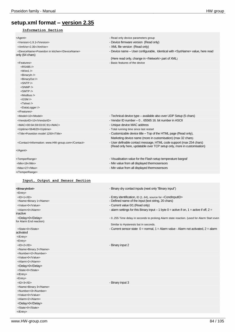
Poseidon family - Manual HW group
www.HW-group.com 84 / 105
setup.xml format – version 2.35
Information Section
<Agent> - Read only device parameters group
<Version>1.9.1</Version> - Device firmware version (Read only)
<XmlVer>2.35</XmlVer> - XML file version (Read only)
<DeviceName>Poseidon in kitchen</DeviceName> - Device name – User configurable, Identical with <SysName> value, here read only (64 chars) (Here read only, change in <Network> part of XML)
<Features> - Basic features of the device
<RS485 />
<Wire1 />
<BinaryIn />
<BinaryOut />
<SNTP />
<SNMP />
<SMTP />
<Modbus />
<GSM />
<Telnet />
<DataLogger />
</Features>
<Model>10</Model> - Technical device type – available also over UDP Setup (5 chars)
<VendorID>10</VendorID> - Vendor ID number – 0 .. 65565 16. bit number in ASCII
<MAC>00:0A:59:03:0C:91</MAC> - Unique device MAC address
<Uptime>564620</Uptime> - Total running time since last restart
<Title>Poseidon model 1250</Title> - Customizable device title – Top of the HTML page (Read only),
Marketing device name (more in customisation) (max 32 chars)
<Contact>Information: www.HW-group.com</Contact> - User definable contact message, HTML code support (max 254 chars) (Read only here, updatable over TCP setup only, more in customisation)
</Agent>
<TemperRange> - Visualisation value for the Flash setup temperature bargraf
<Min>19</Min> - Min value from all displayed thermosensors
<Max>27</Max> - Min value from all displayed thermosensors
</TemperRange>
Input, Output and Sensor Section
<BinaryInSet> - Binary dry contact inputs (next only “Binary input”)
<Entry>
<ID>1</ID> - Entry identification, ID (1..64), source for <CondInputID> <Name>Binary 1</Name> - Defined name of the input (text string, 20 chars)
<Value>0</Value> - Current value 0/1 (Read only)
<Alarm>0</Alarm> - alarm settings for this Binary input – 1 byte 0 = active if on, 1 = active if off, 2 = inactive
<Delay>0</Delay> - 0..255 Time delay in seconds to prolong Alarm state reaction. (used for Alarm Start even
for Alarm End reaction) Similar to Hysteresis but in seconds.
<State>0</State> - Current sensor state 0 = normal, 1 = Alarm value - Alarm not activated, 2 = alarm activated
</Entry>
<Entry>
<ID>2</ID> - Binary input 2
<Name>Binary 2</Name>
<Number>I2</Number>
<Value>0</Value>
<Alarm>2</Alarm>
<Delay>0</Delay>
<State>0</State>
</Entry>
<Entry>
<ID>3</ID> - Binary input 3
<Name>Binary 3</Name>
<Number>I3</Number>
<Value>0</Value>
<Alarm>2</Alarm>
<Delay>0</Delay>
<State>0</State>
</Entry>

Poseidon family - Manual HW group
www.HW-group.com 85 / 105
<AlarmAction>0</AlarmAction> - Alarm routing of Binary digital dry contact inputs (common for all inputs)
0 = inactive, 1 = send SNMP trap,
2 = send Email & SMS
3 = send SNMP trap & Email & SMS
</BinaryInSet>
<BinaryOutSet> - Binary outputs settings & values
<Entry>
<ID>151</ID> - Entry identification, ID (151..214), source for <CondInputID> <Name>RTS</Name> - Output name (Read only)
<Type>1</Type> - Type of the binary outputs 0: X/Y = “On” / “Off” (Relay output), 1: X/Y = “On (+10V)” / “Off (-10V)” (RTS output) 2: X/Y = “On (+10V)” / “Off (0V)” (DTR output)
<Mode>0</Mode> Output control mode (Manual / Local + condition) 0 = Manual output control (value defined by Value tag) 1 = Local output control (On if any alarm) – Poseidon 3268, 1250, 2250 2 = Local output control (On if value equal to Trigger) – Poseidon 3268 future 3 = Local output control (On if value higher than Trigger) – Poseidon 3268 future 4 = Local output control (On if value lower than Trigger) – Poseidon 3268 future 5..8 reserved for Damocles G1,G2
<Value>0</Value> - 0/1 Current output value 0 = Y (“Off” / “Off (-10V)” / “Off (0V)”) 1 = X (“On” / “On (+10V)” / “On (+10V)”) R/W for the „Manual output control” R for the „Local output control” (On if any alarm)
<CondInputID>74</CondInputID> - Condition related input ID – Poseidon 3268 future <Trigger>-18.5</Trigger > - Trigger value for condition – Poseidon 3268 future
</Entry>
<Entry>
<ID>152</ID> - Entry identification <Name>DTR</Name>
<Type>2</Type>
<Value>0</Value>
<Mode>3</Mode>
<CondInputID>75</CondInputID> <Trigger>22.5</Trigger >
</Entry>
</BinaryOutSet>
<SenSet> - All detected sensors
<Entry>
<ID>57856</ID> - Entry identification, Unique ID address of the sensor (Read only), source for
<CondInputID>
<Name>Sensor 240</Name> - Defined name of the sensor (text string, 15 chars)
<Units>C</Units> - Unit of send value "C" for temperature,
"%RH" for humidity, "V" for voltage "mA" for current
“s” for Switch (0/1) “p” for counter pulses (1/10 digit can be used)
<Value>23.0</Value> - Current value, one defimal value, decimal separator is “.” (Read only)
<Calib>-0.15</Calib> - Sensors calibration shift value (Value = Raw sensor value + Calib) Not implemented yet - ready to use in the future
<Min>-1.5</Min> - SafeRange minimal limit
<Max>24.6</Max> - SafeRange maximal limit
<Hyst>0.0</Hyst> - Hysteresis (non sensitivity range) value
<SNMPTrap>1</SNMPTrap> - SNMP trap alarm enable 0 = don't send, 1 = send if value out of SafeRange
<EmailSMS>0</EmailSMS> - E-mail & SMS alarm enable 0 = don't send, 1 = send if value out of SafeRange
<Delay>0</ Delay> - 0..255 Time delay in seconds to prolong Alarm state reaction. (used for Alarm Start even for Alarm End reaction) Similar to Hysteresis but in time
<State>0</State> - Current sensor state
0 = normal, 1 = value out of SafeRange - Alarm not activated,
2 = value out of SafeRange - Alarm activated, 4 = sensor invalid (not connected)
</Entry>
<Entry>
<ID>74</ID>
<Name>Sensor 23</Name>
<Units>C</Units>
<Value>23.8</Value>
<Calib>0.19</Calib>
<Min>10.0</Min>
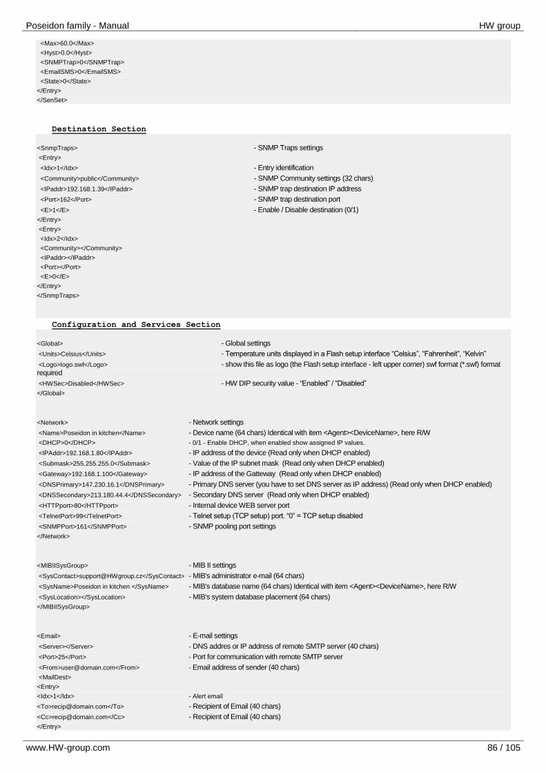
Poseidon family - Manual HW group
www.HW-group.com 86 / 105
<Max>60.0</Max>
<Hyst>0.0</Hyst>
<SNMPTrap>0</SNMPTrap>
<EmailSMS>0</EmailSMS>
<State>0</State>
</Entry>
</SenSet>
Destination Section
<SnmpTraps> - SNMP Traps settings
<Entry>
<Idx>1</Idx> - Entry identification
<Community>public</Community> - SNMP Community settings (32 chars)
<IPaddr>192.168.1.39</IPaddr> - SNMP trap destination IP address
<Port>162</Port> - SNMP trap destination port
<E>1</E> - Enable / Disable destination (0/1)
</Entry>
<Entry>
<Idx>2</Idx>
<Community></Community>
<IPaddr></IPaddr>
<Port></Port>
<E>0</E>
</Entry>
</SnmpTraps>
Configuration and Services Section
<Global> - Global settings
<Units>Celsius</Units> - Temperature units displayed in a Flash setup interface “Celsius”, “Fahrenheit”, “Kelvin”
<Logo>logo.swf</Logo> - show this file as logo (the Flash setup interface - left upper corner) swf format (*.swf) format required
<HWSec>Disabled</HWSec> - HW DIP security value - “Enabled” / “Disabled”
</Global>
<Network> - Network settings
<Name>Poseidon in kitchen</Name> - Device name (64 chars) Identical with item <Agent><DeviceName>, here R/W
<DHCP>0</DHCP> - 0/1 - Enable DHCP, when enabled show assigned IP values.
<IPAddr>192.168.1.80</IPAddr> - IP address of the device (Read only when DHCP enabled)
<Submask>255.255.255.0</Submask> - Value of the IP subnet mask (Read only when DHCP enabled)
<Gateway>192.168.1.100</Gateway> - IP address of the Gatteway (Read only when DHCP enabled)
<DNSPrimary>147.230.16.1</DNSPrimary> - Primary DNS server (you have to set DNS server as IP address) (Read only when DHCP enabled)
<DNSSecondary>213.180.44.4</DNSSecondary> - Secondary DNS server (Read only when DHCP enabled)
<HTTPport>80</HTTPport> - Internal device WEB server port
<TelnetPort>99</TelnetPort> - Telnet setup (TCP setup) port. “0” = TCP setup disabled
<SNMPPort>161</SNMPPort> - SNMP pooling port settings
</Network>
<MIBIISysGroup> - MIB II settings
<SysContact>[email protected]</SysContact> - MIB's administrator e-mail (64 chars)
<SysName>Poseidon in kitchen </SysName> - MIB's database name (64 chars) Identical with item <Agent><DeviceName>, here R/W
<SysLocation></SysLocation> - MIB's system database placement (64 chars)
</MIBIISysGroup>
<Email> - E-mail settings
<Server></Server> - DNS addres or IP address of remote SMTP server (40 chars)
<Port>25</Port> - Port for communication with remote SMTP server
<From>[email protected]</From> - Email address of sender (40 chars)
<MailDest>
<Entry>
<Idx>1</Idx> - Alert email
<To>[email protected]</To> - Recipient of Email (40 chars)
<Cc>[email protected]</Cc> - Recipient of Email (40 chars)
</Entry>
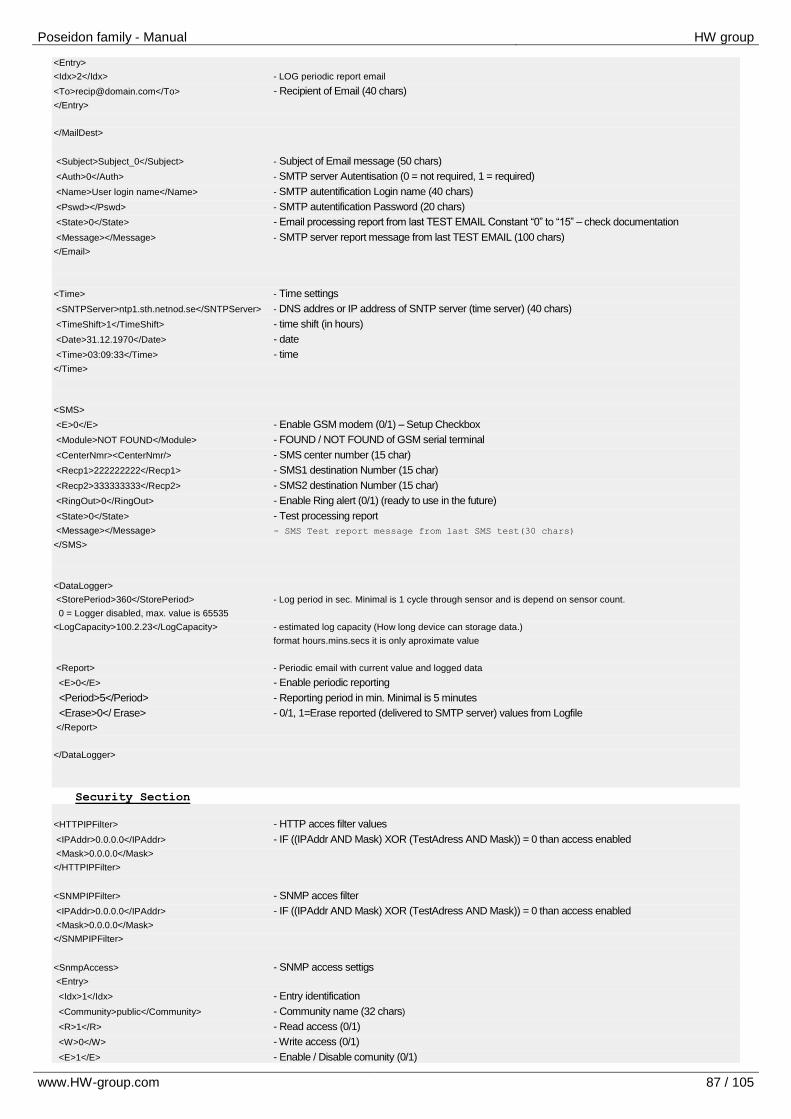
Poseidon family - Manual HW group
www.HW-group.com 87 / 105
<Entry>
<Idx>2</Idx> - LOG periodic report email
<To>[email protected]</To> - Recipient of Email (40 chars)
</Entry>
</MailDest>
<Subject>Subject_0</Subject> - Subject of Email message (50 chars)
<Auth>0</Auth> - SMTP server Autentisation (0 = not required, 1 = required)
<Name>User login name</Name> - SMTP autentification Login name (40 chars)
<Pswd></Pswd> - SMTP autentification Password (20 chars)
<State>0</State> - Email processing report from last TEST EMAIL Constant “0” to “15” – check documentation
<Message></Message> - SMTP server report message from last TEST EMAIL (100 chars)
</Email>
<Time> - Time settings
<SNTPServer>ntp1.sth.netnod.se</SNTPServer> - DNS addres or IP address of SNTP server (time server) (40 chars)
<TimeShift>1</TimeShift> - time shift (in hours)
<Date>31.12.1970</Date> - date
<Time>03:09:33</Time> - time
</Time>
<SMS>
<E>0</E> - Enable GSM modem (0/1) – Setup Checkbox
<Module>NOT FOUND</Module> - FOUND / NOT FOUND of GSM serial terminal
<CenterNmr><CenterNmr/> - SMS center number (15 char)
<Recp1>222222222</Recp1> - SMS1 destination Number (15 char)
<Recp2>333333333</Recp2> - SMS2 destination Number (15 char)
<RingOut>0</RingOut> - Enable Ring alert (0/1) (ready to use in the future)
<State>0</State> - Test processing report
<Message></Message> - SMS Test report message from last SMS test(30 chars)
</SMS>
<DataLogger>
<StorePeriod>360</StorePeriod> - Log period in sec. Minimal is 1 cycle through sensor and is depend on sensor count.
0 = Logger disabled, max. value is 65535
<LogCapacity>100.2.23</LogCapacity> - estimated log capacity (How long device can storage data.)
format hours.mins.secs it is only aproximate value
<Report> - Periodic email with current value and logged data
<E>0</E> - Enable periodic reporting
<Period>5</Period> - Reporting period in min. Minimal is 5 minutes
<Erase>0</ Erase> - 0/1, 1=Erase reported (delivered to SMTP server) values from Logfile
</Report>
</DataLogger>
Security Section
<HTTPIPFilter> - HTTP acces filter values
<IPAddr>0.0.0.0</IPAddr> - IF ((IPAddr AND Mask) XOR (TestAdress AND Mask)) = 0 than access enabled
<Mask>0.0.0.0</Mask>
</HTTPIPFilter>
<SNMPIPFilter> - SNMP acces filter
<IPAddr>0.0.0.0</IPAddr> - IF ((IPAddr AND Mask) XOR (TestAdress AND Mask)) = 0 than access enabled
<Mask>0.0.0.0</Mask>
</SNMPIPFilter>
<SnmpAccess> - SNMP access settigs
<Entry>
<Idx>1</Idx> - Entry identification
<Community>public</Community> - Community name (32 chars)
<R>1</R> - Read access (0/1)
<W>0</W> - Write access (0/1)
<E>1</E> - Enable / Disable comunity (0/1)
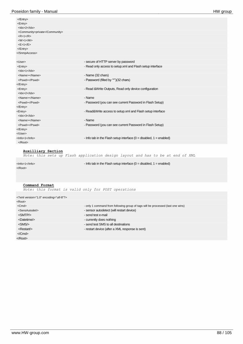
Poseidon family - Manual HW group
www.HW-group.com 88 / 105
</Entry>
<Entry>
<Idx>2</Idx>
<Community>private</Community>
<R>1</R>
<W>1</W>
<E>1</E>
</Entry>
</SnmpAccess>
<User> - secure of HTTP server by password
<Entry> - Read only access to setup.xml and Flash setup interface
<Idx>1</Idx>
<Name></Name> - Name (32 chars)
<Pswd></Pswd> - Password (filled by “*”)(32 chars)
</Entry>
<Entry> - Read &Write Outputs, Read only device configuration
<Idx>2</Idx>
<Name></Name> - Name
<Pswd></Pswd> - Password (you can see current Password in Flash Setup)
</Entry>
<Entry> - Read&Write access to setup.xml and Flash setup interface
<Idx>3</Idx>
<Name></Name> - Name
<Pswd></Pswd> - Password (you can see current Password in Flash Setup)
</Entry>
</User>
<Info>1</Info> - Info tab in the Flash setup interface (0 = disabled, 1 = enabled)
</Root>
Auxilliary Section
Note: this sets up Flash application design layout and has to be at end of XML
<Info>1</Info> - Info tab in the Flash setup interface (0 = disabled, 1 = enabled)
</Root>
Command Format
Note: this format is valid only for POST operations
<?xml version="1.0" encoding="utf-8"?>
<Root>
<Cmd> - only 1 command from following group of tags will be processed (last one wins)
<SensAutodet/> - sensor autodetect (will restart device)
<SMTP/> - send test e-mail
<Datetime/> - currently does nothing
<SMS/> - send test SMS to all destinations
<Restart/> - restart device (after a XML response is sent)
</Cmd>
</Root>
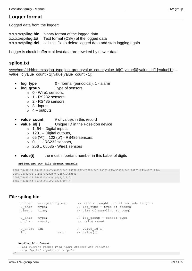
Poseidon family - Manual HW group
www.HW-group.com 89 / 105
Logger format
Logged data from the logger: x.x.x.x/spilog.bin binary format of the logged data x.x.x.x/spilog.txt Text format (CSV) of the logged data x.x.x.x/spilog.del call this file to delete logged data and start logging again Logger is circuit buffer = oldest data are rewrited by newer data.
spilog.txt
yyyy/mm/dd;hh:mm:ss;log_type;log_group;value_count;value_id[0];value[0];value_id[1];value[1]; ... value_id[value_count - 1];value[value_count - 1];
log_type 0 - normal (periodical), 1 - alarm
log_group Type of sensors o 0 - Wire1 sensors, o 1 - RS232 sensors, o 2 - RS485 sensors, o 3 - inputs, o 4 – outputs
value_count # of values in this record
value_id[i] Unique ID in the Poseidon device o 1..64 – Digital inputs, o 128.. – Digital outputs, o 65 ('A') .. 122 ('z') - RS485 sensors, o 0 .. 1 - RS232 sensors, o 256 .. 65535 - Wire1 sensors
value[i] the most important number in this babel of digits
spilog.txt SCV file format example
2007/04/02;14:26:51;0;0;7;54896;243;28078;242;27385;243;25539;245;55499;243;14127;243;4127;246;
2007/04/02;14:26:51;0;2;2;74;245;106;359;
2007/04/02;14:26:51;0;3;3;1;0;2;0;3;0;
2007/04/02;14:26:51;0;4;2;128;0;129;0;
File spilog.bin
u_char occupied_bytes; // record lenght (total include lenght)
u_char type; // log_type - type of record
time_t time; // time of sampling (u_long)
u_char type; // log_group - sensor type
u_char count; // value count
u_short id; // value_id[i]
int val; // value[i]
Aspilog.bin format
- Log current values when Alarm started and finisher
- log digital inputs and outputs
/*
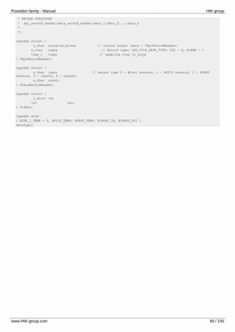
Poseidon family - Manual HW group
www.HW-group.com 90 / 105
* RECORD STRUCTURE
* spi_record_header|data_record_header|data_1|data_2|...|data_n
*
*/
typedef struct
u_char occupied_bytes; // record lenght (data + TSpiRecordHeader)
u_char type; // Record type: LOG_FILE_DATA_TYPE: LOG - 0, ALARM - 1
time_t time; // sampling time (u_long)
TSpiRecordHeader;
typedef struct
u_char type; // Sensor type 0 - Wire1 sensors, 1 - RS232 sensors, 2 - RS485
sensors, 3 - inputs, 4 - outputs
u_char count;
TDataRecordHeader;
typedef struct
u_short id;
int val;
TIdVal;
typedef enum
WIRE_1_TEMP = 0, RS232_TEMP, RS485_TEMP, BINARY_IN, BINARY_OUT
DataType;
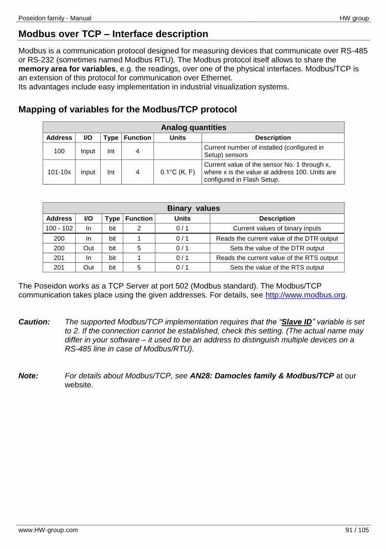
Poseidon family - Manual HW group
www.HW-group.com 91 / 105
Modbus over TCP – Interface description
Modbus is a communication protocol designed for measuring devices that communicate over RS-485 or RS-232 (sometimes named Modbus RTU). The Modbus protocol itself allows to share the memory area for variables, e.g. the readings, over one of the physical interfaces. Modbus/TCP is an extension of this protocol for communication over Ethernet. Its advantages include easy implementation in industrial visualization systems.
Mapping of variables for the Modbus/TCP protocol
Analog quantities
Address I/O Type Function Units Description
100 Input Int 4 Current number of installed (configured in Setup) sensors
101-10x Input Int 4 0.1°C (K, F) Current value of the sensor No. 1 through x, where x is the value at address 100. Units are configured in Flash Setup.
Binary values
Address I/O Type Function Units Description
100 - 102 In bit 2 0 / 1 Current values of binary inputs
200 In bit 1 0 / 1 Reads the current value of the DTR output
200 Out bit 5 0 / 1 Sets the value of the DTR output
201 In bit 1 0 / 1 Reads the current value of the RTS output
201 Out bit 5 0 / 1 Sets the value of the RTS output
The Poseidon works as a TCP Server at port 502 (Modbus standard). The Modbus/TCP communication takes place using the given addresses. For details, see http://www.modbus.org. Caution: The supported Modbus/TCP implementation requires that the “Slave ID” variable is set
to 2. If the connection cannot be established, check this setting. (The actual name may differ in your software – it used to be an address to distinguish multiple devices on a RS-485 line in case of Modbus/RTU).
Note: For details about Modbus/TCP, see AN28: Damocles family & Modbus/TCP at our
website.
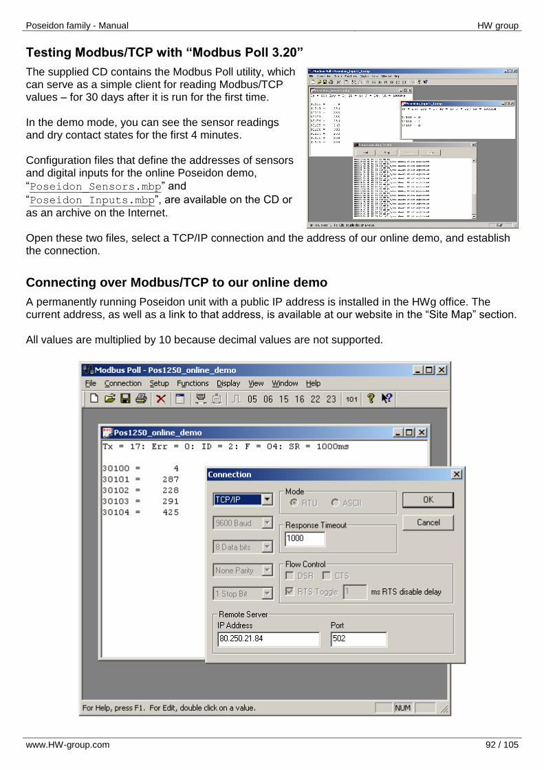
Poseidon family - Manual HW group
www.HW-group.com 92 / 105
Testing Modbus/TCP with “Modbus Poll 3.20”
The supplied CD contains the Modbus Poll utility, which can serve as a simple client for reading Modbus/TCP values – for 30 days after it is run for the first time. In the demo mode, you can see the sensor readings and dry contact states for the first 4 minutes. Configuration files that define the addresses of sensors and digital inputs for the online Poseidon demo,
“Poseidon_Sensors.mbp” and
“Poseidon_Inputs.mbp”, are available on the CD or
as an archive on the Internet. Open these two files, select a TCP/IP connection and the address of our online demo, and establish the connection.
Connecting over Modbus/TCP to our online demo
A permanently running Poseidon unit with a public IP address is installed in the HWg office. The current address, as well as a link to that address, is available at our website in the “Site Map” section. All values are multiplied by 10 because decimal values are not supported.
Poseidon family - Manual HW group
www.HW-group.com 93 / 105
SNMP – Interface description
SNMP (Simple Network Management Protocol) is a protocol designed for exchanging basic system information using short packets sent over UDP/IP. Individual variables are described in a MIB (Management Information Base) table that pertains to a particular device. The MIB is distributed as a separate .mib file. For Poseidon products, the MIB is available on the supplied CD and at our website. SNMP is an asynchronous protocol based on the client/server model (SNMP Client / SNMP Agent in this case). This means that a monitoring center (SNMP Client) requests the states of individual variables, and the SNMP Agent implemented in the device responds. SNMP support is implemented in many languages designed for creating dynamic websites (PHP, ASP, Java, Perl, Python, and so on). Thanks to available modules, read and write access to data provided by a device over SNMP is relatively quick to implement. In the standard communication mode, a “request and response” communication model is used. Variables are defined by a hierarchy (sequence) of numbers that is described in the MIB table, where the meanings, names and formats of individual variables are given. If you know the hierarchy (number sequence, for example “.1.3.6.1.4.1.21796.3.3.1.1.2.3” for the state of the third binary input), you do not need the MIB table. For clarity, the following terms need to be understood:
MIB table – The .mib file is a text file that describes individual variables supported by the device. It contains the addresses, names, descriptions and numeric formats of the variables.
OID is a variable identifier in the table. It is the “long” number that defines the position of the variable in the tree of variables.
Some programs for working with SNMP do not support MIB files. In this case, you need to enter the OID strings manually. These strings can be found in the MIB table. However, to save you some time in first experiments with SNMP, a list of several variables with their OIDs follows:
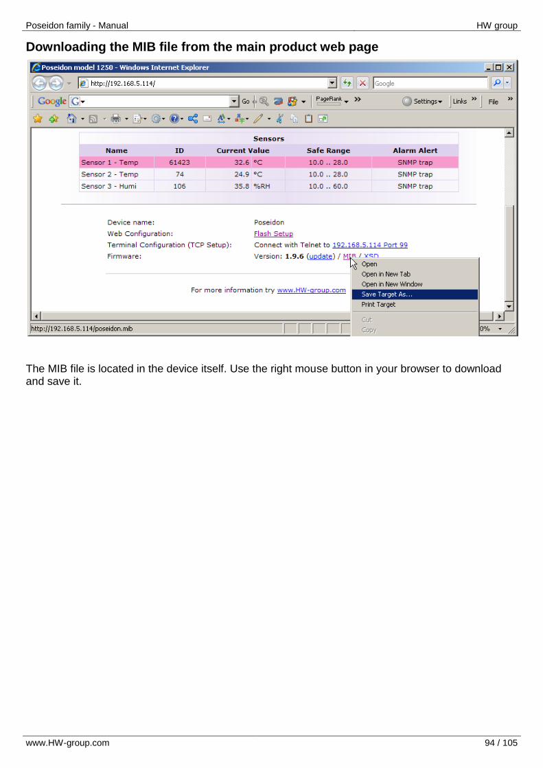
Poseidon family - Manual HW group
www.HW-group.com 94 / 105
Downloading the MIB file from the main product web page
The MIB file is located in the device itself. Use the right mouse button in your browser to download and save it.
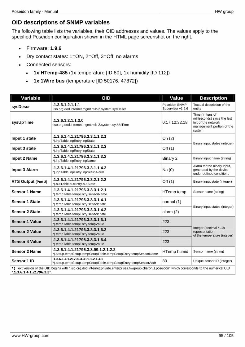
Poseidon family - Manual HW group
www.HW-group.com 95 / 105
OID descriptions of SNMP variables
The following table lists the variables, their OID addresses and values. The values apply to the specified Poseidon configuration shown in the HTML page screenshot on the right.
Firmware: 1.9.6
Dry contact states: 1=ON, 2=Off, 3=Off, no alarms
Connected sensors:
1x HTemp-485 (1x temperature [ID 80], 1x humidity [ID 112])
1x 1Wire bus (temperature [ID 50176, 47872])
Variable OID Value Description
sysDescr .1.3.6.1.2.1.1.1 .iso.org.dod.internet.mgmt.mib-2.system.sysDescr
Poseidon SNMP Supervisor v1.9.6
Textual description of the entity
sysUpTime .1.3.6.1.2.1.1.3.0 .iso.org.dod.internet.mgmt.mib-2.system.sysUpTime
0:17:12:32.18
Time (in tens of milliseconds) since the last init of the network management portion of the system
Input 1 state .1.3.6.1.4.1.21796.3.3.1.1.2.1 *).inpTable.inpEntry.inpState
On (2) Binary input states (integer)
Input 3 state .1.3.6.1.4.1.21796.3.3.1.1.2.3 *).inpTable.inpEntry.inpState
Off (1)
Input 2 Name .1.3.6.1.4.1.21796.3.3.1.1.3.2 *).inpTable.inpEntry.inpName
Binary 2 Binary input name (string)
Input 3 Alarm .1.3.6.1.4.1.21796.3.3.1.1.4.3 *).inpTable.inpEntry.inpSetupAlarm
No (0) Alarm for the binary input, generated by the device under defined conditions
RTS Output (Port 2) .1.3.6.1.4.1.21796.3.3.2.1.2.2 *).outTable.outEntry.outState
Off (1) Binary input state (integer)
Sensor 1 Name .1.3.6.1.4.1.21796.3.3.3.1.2.1 *).tempTable.tempEntry.sensorName
HTemp temp Sensor name (string)
Sensor 1 State .1.3.6.1.4.1.21796.3.3.3.1.4.1 *).tempTable.tempEntry.sensorState
normal (1) Binary input states (integer)
Sensor 2 State .1.3.6.1.4.1.21796.3.3.3.1.4.2 *).tempTable.tempEntry.sensorState
alarm (2)
Sensor 1 Value .1.3.6.1.4.1.21796.3.3.3.1.6.1 *).tempTable.tempEntry.tempValue
223
Integer (decimal * 10) representation of the temperature (integer)
Sensor 2 Value .1.3.6.1.4.1.21796.3.3.3.1.6.2 *).tempTable.tempEntry.tempValue
223
Sensor 4 Value .1.3.6.1.4.1.21796.3.3.3.1.6.4 *).tempTable.tempEntry.tempValue
223
Sensor 2 Name .1.3.6.1.4.1.21796.3.3.99.1.2.1.2.2 *).setup.tempSetup.tempSetupTable.tempSetupEntry.tempSensorName
HTemp humid Sensor name (string)
Sensor 1 ID .1.3.6.1.4.1.21796.3.3.99.1.2.1.4.1 *).setup.tempSetup.tempSetupTable.tempSetupEntry.tempSensorAddr
80 Unique sensor ID (integer)
*) Text version of the OID begins with “.iso.org.dod.internet.private.enterprises.hwgroup.charonII.poseidon” which corresponds to the numerical OID “.1.3.6.1.4.1.21796.3.3”.
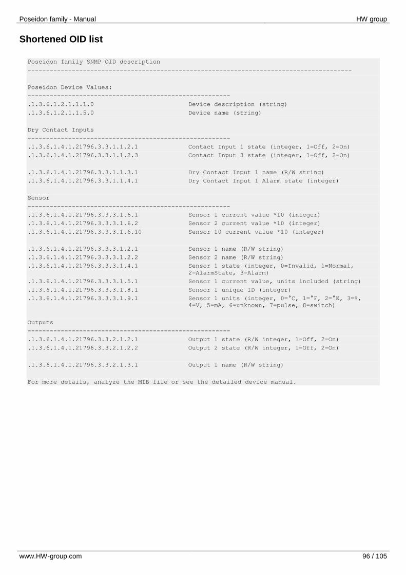
Poseidon family - Manual HW group
www.HW-group.com 96 / 105
Shortened OID list
Poseidon family SNMP OID description
----------------------------------------------------------------------------------------
Poseidon Device Values:
-------------------------------------------------------
.1.3.6.1.2.1.1.1.0 Device description (string)
.1.3.6.1.2.1.1.5.0 Device name (string)
Dry Contact Inputs
-------------------------------------------------------
.1.3.6.1.4.1.21796.3.3.1.1.2.1 Contact Input 1 state (integer, 1=Off, 2=On)
.1.3.6.1.4.1.21796.3.3.1.1.2.3 Contact Input 3 state (integer, 1=Off, 2=On)
.1.3.6.1.4.1.21796.3.3.1.1.3.1 Dry Contact Input 1 name (R/W string)
.1.3.6.1.4.1.21796.3.3.1.1.4.1 Dry Contact Input 1 Alarm state (integer)
Sensor
-------------------------------------------------------
.1.3.6.1.4.1.21796.3.3.3.1.6.1 Sensor 1 current value *10 (integer)
.1.3.6.1.4.1.21796.3.3.3.1.6.2 Sensor 2 current value *10 (integer)
.1.3.6.1.4.1.21796.3.3.3.1.6.10 Sensor 10 current value *10 (integer)
.1.3.6.1.4.1.21796.3.3.3.1.2.1 Sensor 1 name (R/W string)
.1.3.6.1.4.1.21796.3.3.3.1.2.2 Sensor 2 name (R/W string)
.1.3.6.1.4.1.21796.3.3.3.1.4.1 Sensor 1 state (integer, 0=Invalid, 1=Normal,
2=AlarmState, 3=Alarm)
.1.3.6.1.4.1.21796.3.3.3.1.5.1 Sensor 1 current value, units included (string)
.1.3.6.1.4.1.21796.3.3.3.1.8.1 Sensor 1 unique ID (integer)
.1.3.6.1.4.1.21796.3.3.3.1.9.1 Sensor 1 units (integer, 0=°C, 1=°F, 2=°K, 3=%,
4=V, 5=mA, 6=unknown, 7=pulse, 8=switch)
Outputs
-------------------------------------------------------
.1.3.6.1.4.1.21796.3.3.2.1.2.1 Output 1 state (R/W integer, 1=Off, 2=On)
.1.3.6.1.4.1.21796.3.3.2.1.2.2 Output 2 state (R/W integer, 1=Off, 2=On)
.1.3.6.1.4.1.21796.3.3.2.1.3.1 Output 1 name (R/W string)
For more details, analyze the MIB file or see the detailed device manual.
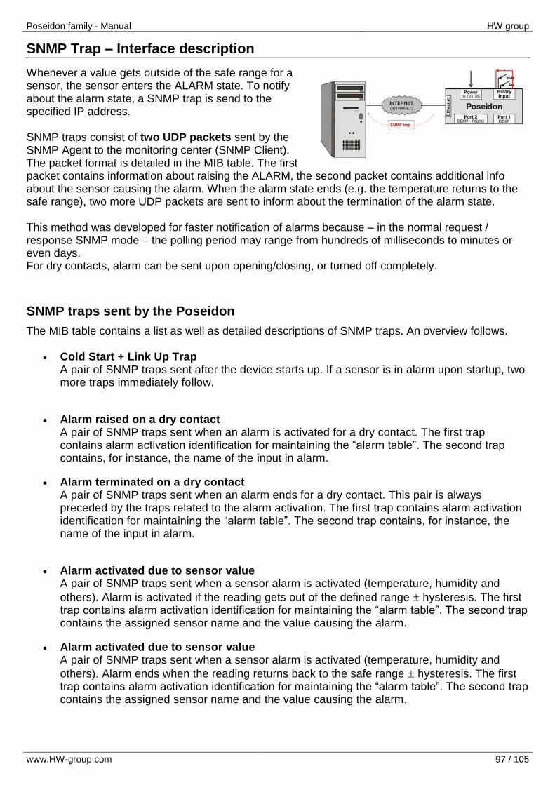
Poseidon family - Manual HW group
www.HW-group.com 97 / 105
SNMP Trap – Interface description
Whenever a value gets outside of the safe range for a sensor, the sensor enters the ALARM state. To notify about the alarm state, a SNMP trap is send to the specified IP address. SNMP traps consist of two UDP packets sent by the SNMP Agent to the monitoring center (SNMP Client). The packet format is detailed in the MIB table. The first packet contains information about raising the ALARM, the second packet contains additional info about the sensor causing the alarm. When the alarm state ends (e.g. the temperature returns to the safe range), two more UDP packets are sent to inform about the termination of the alarm state. This method was developed for faster notification of alarms because – in the normal request / response SNMP mode – the polling period may range from hundreds of milliseconds to minutes or even days. For dry contacts, alarm can be sent upon opening/closing, or turned off completely.
SNMP traps sent by the Poseidon
The MIB table contains a list as well as detailed descriptions of SNMP traps. An overview follows.
Cold Start + Link Up Trap A pair of SNMP traps sent after the device starts up. If a sensor is in alarm upon startup, two more traps immediately follow.
Alarm raised on a dry contact A pair of SNMP traps sent when an alarm is activated for a dry contact. The first trap contains alarm activation identification for maintaining the “alarm table”. The second trap contains, for instance, the name of the input in alarm.
Alarm terminated on a dry contact A pair of SNMP traps sent when an alarm ends for a dry contact. This pair is always preceded by the traps related to the alarm activation. The first trap contains alarm activation identification for maintaining the “alarm table”. The second trap contains, for instance, the name of the input in alarm.
Alarm activated due to sensor value A pair of SNMP traps sent when a sensor alarm is activated (temperature, humidity and
others). Alarm is activated if the reading gets out of the defined range hysteresis. The first trap contains alarm activation identification for maintaining the “alarm table”. The second trap contains the assigned sensor name and the value causing the alarm.
Alarm activated due to sensor value A pair of SNMP traps sent when a sensor alarm is activated (temperature, humidity and
others). Alarm ends when the reading returns back to the safe range hysteresis. The first trap contains alarm activation identification for maintaining the “alarm table”. The second trap contains the assigned sensor name and the value causing the alarm.
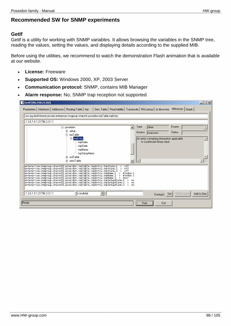
Poseidon family - Manual HW group
www.HW-group.com 98 / 105
Recommended SW for SNMP experiments
GetIf Getif is a utility for working with SNMP variables. It allows browsing the variables in the SNMP tree, reading the values, setting the values, and displaying details according to the supplied MIB. Before using the utilities, we recommend to watch the demonstration Flash animation that is available at our website.
License: Freeware
Supported OS: Windows 2000, XP, 2003 Server
Communication protocol: SNMP, contains MIB Manager
Alarm response: No, SNMP trap reception not supported
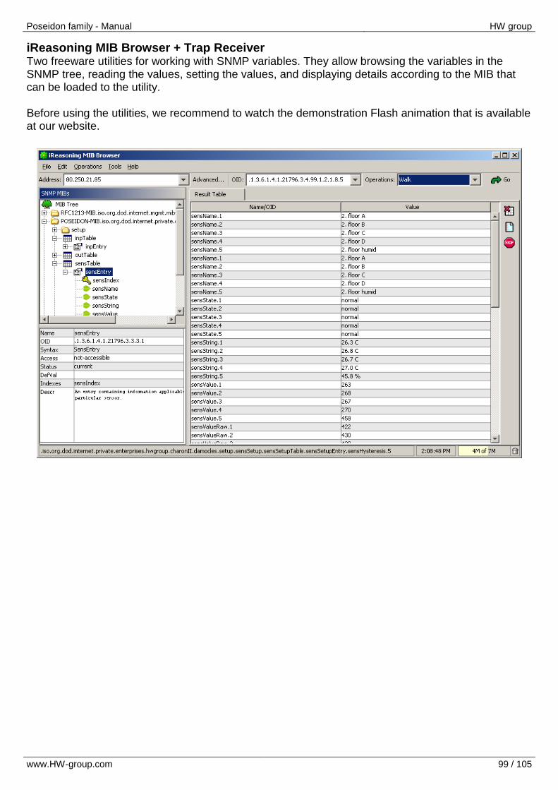
Poseidon family - Manual HW group
www.HW-group.com 99 / 105
iReasoning MIB Browser + Trap Receiver Two freeware utilities for working with SNMP variables. They allow browsing the variables in the SNMP tree, reading the values, setting the values, and displaying details according to the MIB that can be loaded to the utility. Before using the utilities, we recommend to watch the demonstration Flash animation that is available at our website.
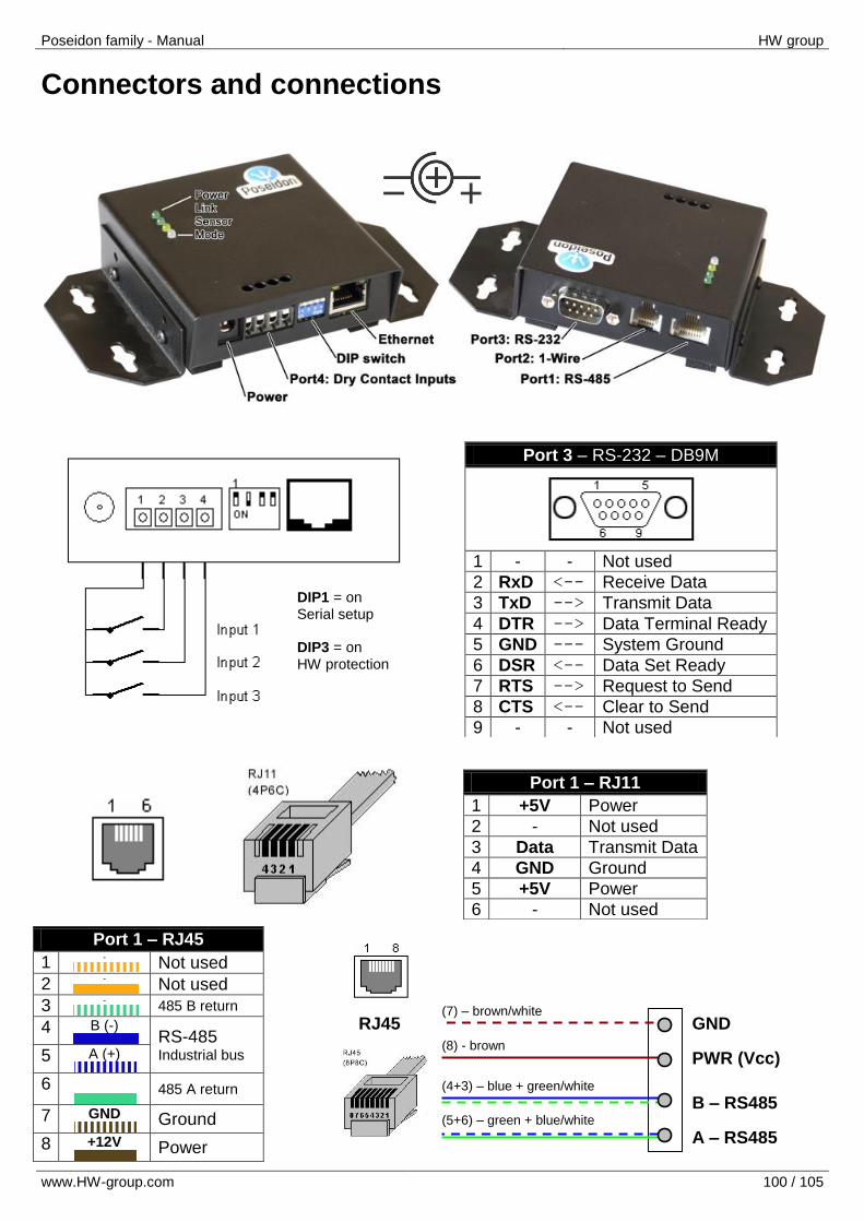
Poseidon family - Manual HW group
www.HW-group.com 100 / 105
Connectors and connections
Port 3 – RS-232 – DB9M
1 - - Not used
2 RxD <-- Receive Data
3 TxD --> Transmit Data
4 DTR --> Data Terminal Ready
5 GND --- System Ground
6 DSR <-- Data Set Ready
7 RTS --> Request to Send
8 CTS <-- Clear to Send
9 - - Not used
Port 1 – RJ11
1 +5V Power
2 - Not used
3 Data Transmit Data
4 GND Ground
5 +5V Power
6 - Not used
Port 1 – RJ45
1 -
Not used
2 -
Not used
3 -
485 B return
4 B (-) RS-485
Industrial bus 5 A (+)
6
485 A return
7 GND
Ground
8 +12V
Power
DIP1 = on Serial setup DIP3 = on HW protection
(7) – brown/white
(8) - brown
(4+3) – blue + green/white
(5+6) – green + blue/white
RJ45
GND PWR (Vcc)
B – RS485 A – RS485

Poseidon family - Manual HW group
www.HW-group.com 101 / 105
Industrial Bus (RS-485) connections
Connecting the 4-terminal block to the RJ45 jack
Connecting certain sensors
Connecting Pt100 sensors
Pt100 and Pt1000 sensors normally require a 3-wire connection
All three wires must have the same properties (diameter, …)
When connecting a Pt100 using two wires only, connect the third terminal locally
Addresses of Temp-485 units with Pt100 sensors
When shipped, the configured sensor address is in the A..Z range and shown on the label.
Address on the RS-485 bus can be changed in the TCP setup mode, see the “Configuring temperature sensors in TCP Setup” section.
- +
A
B (7) – brown/white
(8) - brown
(4+3) – blue + green/white
(5+6) – green + blue/white
RS
-485 b
us
RJ45
co
nn
ecto
r
1 2 3
Pt100 & Pt1000 connections
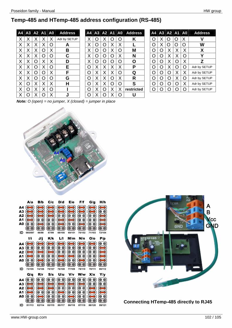
Poseidon family - Manual HW group
www.HW-group.com 102 / 105
Temp-485 and HTemp-485 address configuration (RS-485)
A4 A3 A2 A1 A0 Address A4 A3 A2 A1 A0 Address A4 A3 A2 A1 A0 Address
X X X X X Adr by SETUP X O X O O K O X O O X V
X X X X O A X O O X X L O X O O O W
X X X O X B X O O X O M O O X X X X
X X X O O C X O O O X N O O X X O Y
X X O X X D X O O O O O O O X O X Z
X X O X O E O X X X X P O O X O O Adr by SETUP
X X O O X F O X X X O Q O O O X X Adr by SETUP
X X O O O G O X X O X R O O O X O Adr by SETUP
X O X X X H O X X O O S O O O O X Adr by SETUP
X O X X O I O X O X X restricted O O O O O Adr by SETUP
X O X O X J O X O X O U
Note: O (open) = no jumper, X (closed) = jumper in place
Connecting HTemp-485 directly to RJ45

Poseidon family - Manual HW group
www.HW-group.com 103 / 105
List of ordering IDs
OID Product name Product description
600 080 Wall power adaptor 12V Power supply adaptor 0.5A, Euro plug (UK = 600 082, US = 600 081)
600 251 Back-up power supply 12V Power supply 12V / 0.4 A backed up with a rechargeable battery
600 023 2x Wall Bracket "A" size “L” brackets for mounting on a wall
Note: Ordering ID numbers (OID) for our products mentioned here may change. Please see our
website for valid OID numbers before placing your order.
1Wire bus (RJ11)
Up to 10 sensors connected at the same time, maximum bus length 10m
600 005 Temp-1Wire 3m Temperature sensor, 3m cable (1m = 600 242 , 10m = 600 056)
600 279 Humid-1Wire 3m Humidity sensor, 3m cable (1m = 600 278)
600 040 Poseidon T-Box Hub to connect five RJ11 sensors to the unit
600 280 Poseidon T-Box2 Hub to connect two RJ11 sensors to the unit, 3m cable
Industrial bus – RS-485 (RJ45)
Up to 31 sensors connected at the same time, maximum bus length 1000m
600 041 Poseidon S-Hub Hub to connect up to 8 sensors to the RS-485 bus (8x RJ45)
600 233 Sensor RJ45 MIDDLE cable Cable 0.5m to connect sensors with a terminal block to a RJ45 jack
600 044 Poseidon B-Cable RS-485 adapter – converts RJ45 to a block of 4 terminals ( A,B,+,- )
600 273 Spider-485 Connects up to four 1-Wire (RJ11) sensors to RS-485
600 105 Temp-485 Temperature sensor – vertical wall mount, indoor use
600 106 HTemp-485 Temperature and humidity sensor – vertical wall mount, indoor use
600 116 Sens-485-UI Voltage (0..15V) and current (0..25mA) sensor, DIN rail
600 113 Temp-485-Pt100 “Box” Platinum temperature sensor, accuracy: ±0.15°C, IP65 for outdoor use
600 114 Temp-485-Pt100 “Cable” Pt100 – platinum temperature sensor on a 2m cable, ±0.2 °C
600 112 Temp-485-2xPt100 “DIN” Adapter for two external Pt100 temperature sensors, DIN rail
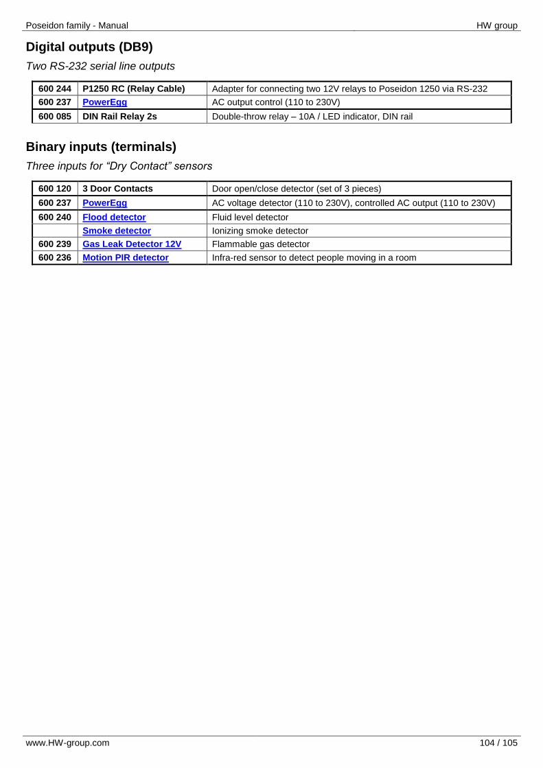
Poseidon family - Manual HW group
www.HW-group.com 104 / 105
Digital outputs (DB9)
Two RS-232 serial line outputs
600 244 P1250 RC (Relay Cable) Adapter for connecting two 12V relays to Poseidon 1250 via RS-232
600 237 PowerEgg AC output control (110 to 230V)
600 085 DIN Rail Relay 2s Double-throw relay – 10A / LED indicator, DIN rail
Binary inputs (terminals)
Three inputs for “Dry Contact” sensors
600 120 3 Door Contacts Door open/close detector (set of 3 pieces)
600 237 PowerEgg AC voltage detector (110 to 230V), controlled AC output (110 to 230V)
600 240 Flood detector Fluid level detector
Smoke detector Ionizing smoke detector
600 239 Gas Leak Detector 12V Flammable gas detector
600 236 Motion PIR detector Infra-red sensor to detect people moving in a room
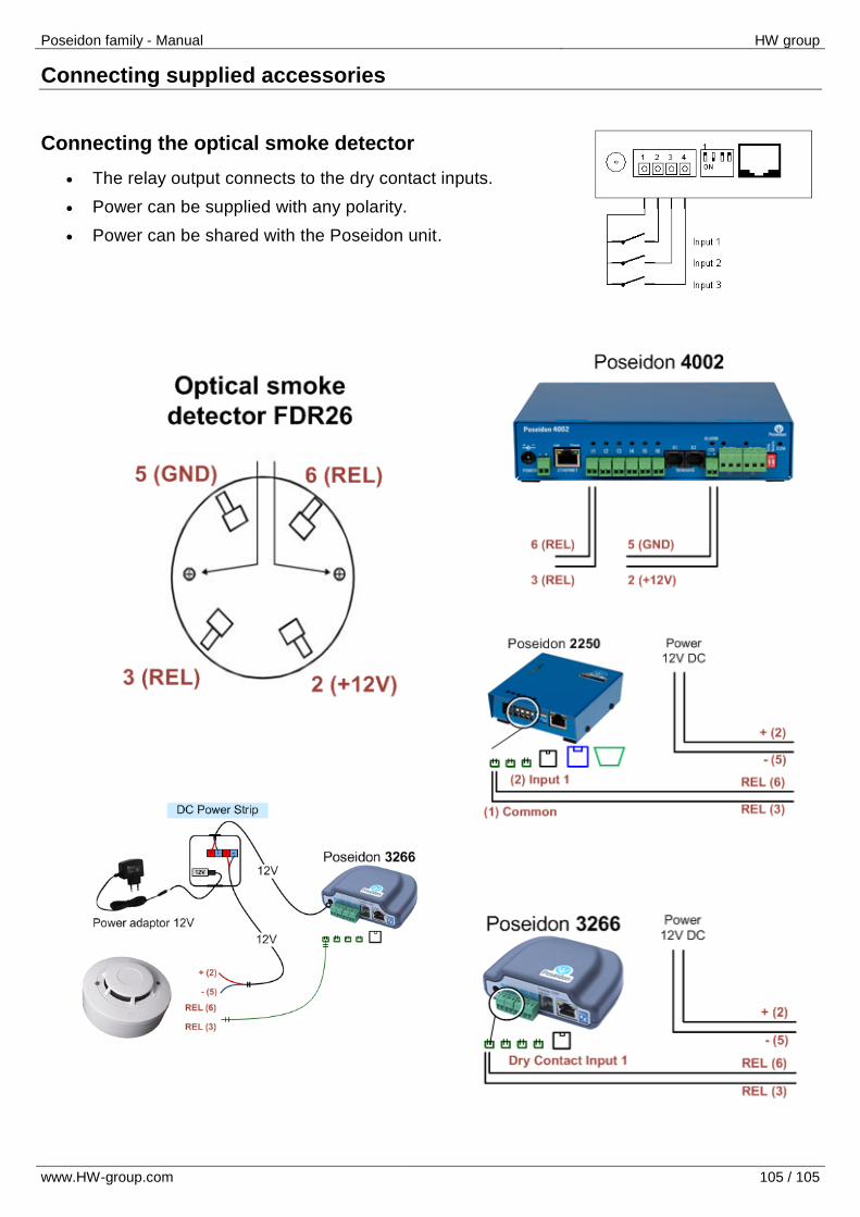
Poseidon family - Manual HW group
www.HW-group.com 105 / 105
Connecting supplied accessories
Connecting the optical smoke detector
The relay output connects to the dry contact inputs.
Power can be supplied with any polarity.
Power can be shared with the Poseidon unit.