Embed Size (px)
Citation preview

Poseidon 4002 MANUAL
Poseidon 4002 – manual HW group
www.HW-group.com
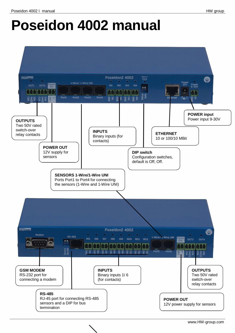
Poseidon 4002 manual
INPUTS Binary inputs 1–6 (for contacts)
POWER input Power input 9-30V
ETHERNET 10 or 100/10 MBit
DIP switch Configuration switches, default is Off, Off.
OUTPUTS Two 50V rated switch-over relay contacts 0V
POWER OUT 12V supply for sensors
SENSORS 1-Wire/1-Wire UNI Ports Port1 to Port4 for connecting the sensors (1-Wire and 1-Wire UNI)
GSM MODEM RS-232 port for connecting a modem
POWER OUT 12V power supply for sensors
RS-485 RJ-45 port for connecting RS-485 sensors and a DIP for bus termination
OUTPUTS Two 50V rated switch-over relay contacts
INPUTS Binary inputs (for contacts)
Poseidon 4002 – manual HW group
www.HW-group.com
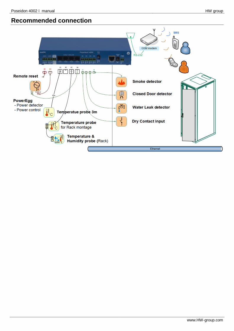
Recommended connection
Poseidon 4002 – manual HW group
www.HW-group.com
First steps
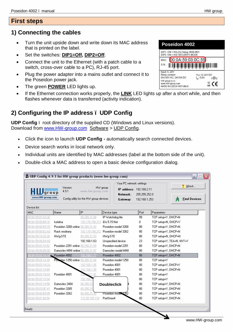
1) Connecting the cables • Turn the unit upside down and write down its MAC address
that is printed on the label. • Set the switches: DIP1=Off, DIP2=Off. • Connect the unit to the Ethernet (with a patch cable to a
switch, cross-over cable to a PC), RJ-45 port. • Plug the power adapter into a mains outlet and connect it to
the Poseidon power jack. • The green POWER LED lights up. • If the Ethernet connection works properly, the LINK LED lights up after a short while, and then
flashes whenever data is transferred (activity indication). 2) Configuring the IP address – UDP Config UDP Config – root directory of the supplied CD (Windows and Linux versions). Download from www.HW-group.com Software > UDP Config.
• Click the icon to launch UDP Config - automatically search connected devices. • Device search works in local network only. • Individual units are identified by MAC addresses (label at the bottom side of the unit). • Double-click a MAC address to open a basic device configuration dialog.
Poseidon 4002
Doubleclick

Poseidon 4002 – manual HW group
www.HW-group.com
First steps Configure network parameters
• IP address / HTTP port (80 by default) • Network mask • Gateway IP address for your network • Device name (optional)
Click the Apply Changes button to save the settings. You may also use the following utilities to configure the IP address:
• UDP Config for Linux • RS-232 serial port (any terminal program, 9600 8N1, DIP1=ON, restart)
IMPORTANT:
• To reset the device to factory defaults, toggle DIP1 several times within 5 seconds after power-up.
• No configuration changes can be stored while DIP2=On. To change the IP address, set DIP2=Off.
First steps 4) WWW interface of the device
• To open the WWW interface of the device: o Enter the IP address into a web browser o Click the IP address in UDP Config o Click the underlined IP address in UDP
SETUP • The WWW page displays current states of inputs and outputs. • Click the “Web SETUP” link to open the graphical configuration interface.
Poseidon 4002 – manual HW group
www.HW-group.com
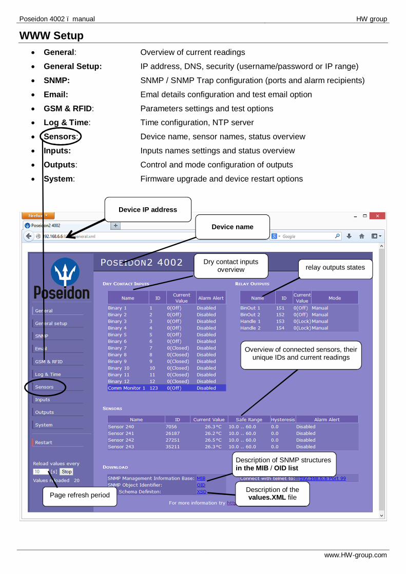
WWW Setup • General: Overview of current readings
• General Setup: IP address, DNS, security (username/password or IP range)
• SNMP: SNMP / SNMP Trap configuration (ports and alarm recipients)
• Email: Emal details configuration and test email option
• GSM & RFID: Parameters settings and test options • Log & Time: Time configuration, NTP server
• Sensors: Device name, sensor names, status overview
• Inputs: Inputs names settings and status overview
• Outputs: Control and mode configuration of outputs
• System: Firmware upgrade and device restart options
Device name
Description of the values.XML file
Device IP address
Description of SNMP structures in the MIB / OID list
Dry contact inputs overview relay outputs states
Overview of connected sensors, their unique IDs and current readings
Page refresh period

Poseidon 4002 – manual HW group
www.HW-group.com
General Setup
User Passwords Allows setting user name and password for two different user accounts for SNMP and HTTP access.
• Account type: • ‘Read Only’ user can only see the settings and read the values • ‘Read Only + Outputs’ can read the values, switch outputs, but cannot change
the device settings • ‘Read & Write’ user is allowed to change the settings
IP Access Filter
Allows defining the IP addresses range for SNMP and HTTP access. Each protocol has its own IP range.
Device name Basic network parameters
Temperature unit format (°C, °F, K)
Security settings - user name and password

Poseidon 4002 – manual HW group
www.HW-group.com
Warning: Configuration changes must be confirmed by clicking the Apply Changes button.
Sends a test e-mail and shows the connection log
1) Correct Gateway IP address 2) DNS server in network settings 3) SMTP server and port 4) Authentication turned on, correct
username and password 5) Spam filter for your mailbox is
disabled
To send emails, check:

Poseidon 4002 – manual HW group
www.HW-group.com
Sensors
Warning: Configuration changes must be confirmed by clicking the Apply Changes button.
Enter sensor name, will be shown in E-mail, SMS or
SNMP traps
Sends a SNMP trap if the “Safe Range” for this sensor is
exceeded.
Scans connected sensors and displays detected sensors
Sends an email and SMS if the “Safe Range” for this sensor is
exceeded.
To avoid numerous false alerts (by e-mail or SMS) whenever the reading fluctuates around the threshold, you can use:
1) Hysteresis Idle Range Tolerance band around the “Safe Range”. Prevents multiple alarm alerts.
2) Delay [s] Delays the information about alarm beginning and alarm end by a specified time. Can be used for binary contacts, too.
Tip: For details, see the complete “Poseidon family” manual.
Poseidon 4002 – manual HW group
www.HW-group.com
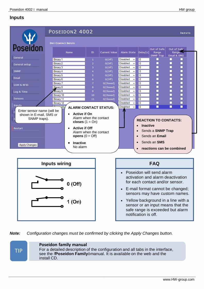
• Poseidon will send alarm activation and alarm deactivation for each contact and/or sensor.
• E-mail format cannot be changed; sensors may have custom names.
• Yellow background in a line with a sensor or an input means that the safe range is exceeded but alarm notification is off.
FAQ
Inputs wiring
Inputs
Note: Configuration changes must be confirmed by clicking the Apply Changes button.
• Poseidon family manualFor a detailed description of the configuration and all tabs in the interface, see the “Poseidon Family” manual. It is available on the web and the install CD.
TIP
Enter sensor name (will be shown in E-mail, SMS or
SNMP traps).
ALARM CONTACT STATUS:
• Active if On Alarm when the contact closes (1 = On)
• Active if Off Alarm when the contact opens (0 = Off)
• Inactive No alarm
REACTION TO CONTACTS: • Inactive • Sends a SNMP Trap • Sends an Email • Sends an SMS
• reactions can be combined
Poseidon 4002 – manual HW group
www.HW-group.com
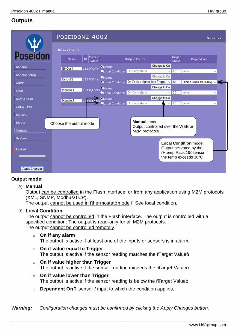
Outputs
Output mode:
A) Manual Output can be controlled in the Flash interface, or from any application using M2M protocols (XML, SNMP, Modbus/TCP). The output cannot be used in “thermostat” mode – See local condition.
B) Local Condition The output cannot be controlled in the Flash interface. The output is controlled with a specified condition. The output is read-only for all M2M protocols. The output cannot be controlled remotely.
o On if any alarm The output is active if at least one of the inputs or sensors is in alarm.
o On if value equal to Trigger The output is active if the sensor reading matches the “Target Value”.
o On if value higher than Trigger The output is active if the sensor reading exceeds the “Target Value”.
o On if value lower than Trigger The output is active if the sensor reading is below the “Target Value”.
o Dependent On – sensor / input to which the condition applies. Warning: Configuration changes must be confirmed by clicking the Apply Changes button.
Choose the output mode Manual mode: Output controlled over the WEB or M2M protocols
Local Condition mode: Output activated by the “Htemp Rack 19” sensor if the temp exceeds 30°C
Poseidon 4002 – manual HW group
www.HW-group.com
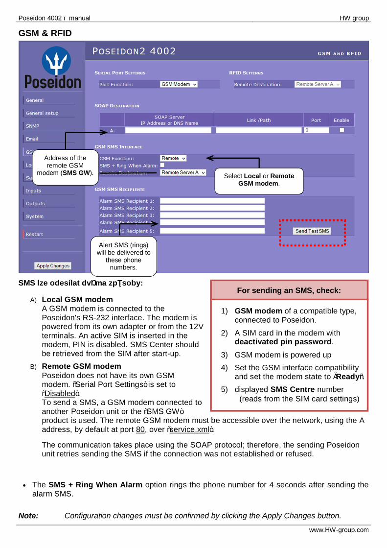
1) GSM modem of a compatible type, connected to Poseidon.
2) A SIM card in the modem with deactivated pin password.
3) GSM modem is powered up 4) Set the GSM interface compatibility
and set the modem state to „Ready“. 5) displayed SMS Centre number
(reads from the SIM card settings)
For sending an SMS, check:
GSM & RFID
SMS lze odesílat dvěma způsoby:
A) Local GSM modem A GSM modem is connected to the Poseidon's RS-232 interface. The modem is powered from its own adapter or from the 12V terminals. An active SIM is inserted in the modem, PIN is disabled. SMS Center should be retrieved from the SIM after start-up.
B) Remote GSM modem Poseidon does not have its own GSM modem. “Serial Port Settings” is set to “Disabled”. To send a SMS, a GSM modem connected to another Poseidon unit or the “SMS GW” product is used. The remote GSM modem must be accessible over the network, using the A address, by default at port 80, over “service.xml”.
The communication takes place using the SOAP protocol; therefore, the sending Poseidon unit retries sending the SMS if the connection was not established or refused.
• The SMS + Ring When Alarm option rings the phone number for 4 seconds after sending the alarm SMS.
Note: Configuration changes must be confirmed by clicking the Apply Changes button.
Select Local or Remote GSM modem.
Address of the remote GSM
modem (SMS GW).
Alert SMS (rings) will be delivered to
these phone numbers.

Poseidon 4002 – manual HW group
www.HW-group.com
Software Applications HWg-PDMS HWg-PDMS is a Windows application for data logging and quick export of reports to MS Excel. Sensor readings from connected devices are stored in a database. Readings are received over XML (http) or e-mail. Works with the PD Trigger application to process alarms. The database can be accessed from a MS EXCEL sheet, or through an API (examples are available for .NET, VB, C#, Borland C++, Delphi, Microsoft C++). HWg-PDMS: Free version for 3 sensors available for your trial.
PD Trigger To react to alarms and to control outputs, the PD Trigger application can be used. It reacts to incoming Alarm alerts by, for instance, activating a networked relay. (Available for download at our website.)
HWg-PD Trigger: Free version for 2 conditions available for your trial.
Poseidon 4002 – manual HW group
www.HW-group.com
PosDamIO Poseidon Damocles I/O is a command-line utility for Windows and Linux that lets you control Poseidon and Damocles units over the XML interface. It can display the states of sensors, inputs and outputs, as well as set an output high or low.
3rd party applications
HW group maintains a database of software applications tested with Poseidon family. This applications overview can be found on HWg websites:
• SNMP Network Management applications • IP camera systems • Security applications
Poseidon 4002 – manual HW group
www.HW-group.com
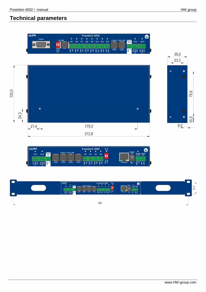
Technical parameters

Poseidon 4002 – manual HW group
www.HW-group.com
Product specifications
• Ethernet: RJ45 – 10BASE-T/10 Mbit/s • Communication: WEB, SNMP, XML, SMTP, DHCP
• 4x 1-Wire sensor ports: RJ11 ports for connecting 1-Wire probes (temperature, humidity...)
o Supports up to 16 sensors in total - 1-Wire or 1-Wire UNI type
• 1x RS-485 : RJ45 o Up to 26 HW Group sensors
• 12 digital inputs: Dry contact inputs • 4 digital outputs: realy contact outputs, each output controls a NO and NC contact.
• Control DIP switch
o DIP1 = On activates a Serial SETUP mode (9600 8N1) Restores the factory defaults, if toggled 5x within 5 seconds after powering up the device
o DIP2 = On blocks changes in configuration.
• Device functions o Alarm when a preset threshold is exceeded o Remote monitoring of input states and temperature sensors o Remote relay output control o Local relay output control with Alarm conditions (Local Condition)
• Power supply: +9-30V / 250 mA
• Dimensions: 213 x 100 x 35 [mm] (H x W x D) / 360 g (1U) • LED indicators: Power, LINK, STATUS, ALARM, INPUTS, OUTPUTS

Poseidon 4002 – manual HW group
www.HW-group.com
ETHERNET Interface RJ45 (100BASE-Tx) – 10/100 Mbps network compatible Supported protocols IP: ARP, TCP/IP (HTTP, NTP, SMTP, netGSM, HWg-PUSH), UDP/IP (SNMP) SNMP compatibility Ver.1.00 compatible, partial ver.2.0 implementation
SENSORS 1-Wire Type HWg original accessories: 1-Wire & 1-Wire Uni Connector RJ11 4x Sensors Up to 16 sensors in total (temperature + humidity combo sensors count as 2 sensors) Sensor distance Up to 60m SENSORS RJ-45 Type HWg original accessories Connector RJ45 + 2x DIP for termination Sensors Up to 26 sensors in total (temperature + humidity combo sensors count as 2 sensors) Sensor distance Up to 1000m DRY CONTACT INPUTS Port IN1-IN12 Type Digital Input (supports NO/NC Dry contact) Sensitivity 1 (On) = 0-500 Ω (Right pin on the terminal block can be connected to 12V GND) Max. distance Up to 50m OUTPUTS Port / type OUT1 - OUT4 / Relay contacts (NC-COM-NO) Max. Voltage 120V AC/60V DC Max. load Max 1A, up to 60VA/24W ( 0.5A/48V) State Power up state (no state restart memory) POWER input Port POWER 9-30V DC Type Main device power input (typically 250 mA)
Connector Jack (barrel, inner 2.5 mm outer 6.3 mm), Terminal Block
LED Status indicators POWER (RJ45 + top) Green - power OK (top), Ethernet enable (RJ45) LINK & Activity (RJ45) Yellow - Ethernet connectivity Setup / Alarm Red Input Green Output Yellow DIP SWITCH
DIP1: Setup ON = RS-232 Setup mode over serial port (RS-232 mode only) Load defaults: Set ON, power-up device, toggle 3 times during first 5 seconds to load defaults
DIP2: Security ON = Security mode - remote configuration disabled OFF = Non-secure mode - remote configuration enabled
Physical parameters Temperature range Operating: -30 to +85 °C (+14 to +150 °F) / Storage: -35 to +85 °C (-13 to +185 °F) Dimensions / Weight 213 x 100 x 35 [mm] (H x W x D) / 360 g EMC FCC Part 15, Class B, CE - EN 55022, EN 55024, EN 61000
Poseidon 4002 – manual HW group
www.HW-group.com
I1
NO
+
-
COM
POWER OUT 12V
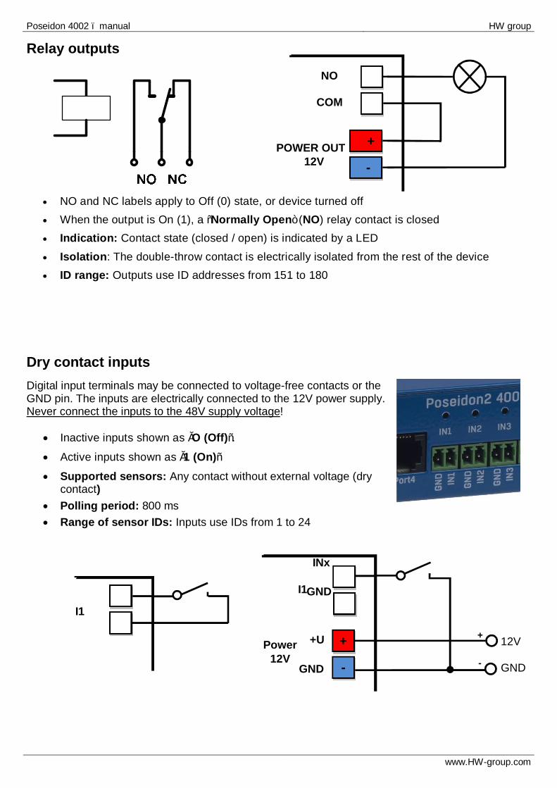
Relay outputs
• NO and NC labels apply to Off (0) state, or device turned off • When the output is On (1), a “Normally Open” (NO) relay contact is closed • Indication: Contact state (closed / open) is indicated by a LED • Isolation: The double-throw contact is electrically isolated from the rest of the device • ID range: Outputs use ID addresses from 151 to 180
Dry contact inputs Digital input terminals may be connected to voltage-free contacts or the GND pin. The inputs are electrically connected to the 12V power supply. Never connect the inputs to the 48V supply voltage!
• Inactive inputs shown as „O (Off)“. • Active inputs shown as „1 (On)“ • Supported sensors: Any contact without external voltage (dry
contact) • Polling period: 800 ms • Range of sensor IDs: Inputs use IDs from 1 to 24
I1
INx
Power 12V
+
-
12V GND
+
-
+U
GND
GND

Poseidon 4002 – manual HW group
www.HW-group.com
M2M interface This product can be used with third-party SW applications. For a description of the interfaces (XML format, detailed description of SNMP, mapping of Modbus/TCP variables), see the detailed “Poseidon family” manual.
• XML (over HTTP) • SNMP, SNMP traps • Modbus/TCP • SMTP (E-mail)
SDK (Software Development Kit) Programmers can take advantage of the HWg SDK (Software Development Kit) with an ActiveX interface and ready-made examples.
• VB - Visual Basic (6.0) - (3xx examples)
• Borland C++ (1xx examples) • Microsoft Visual C++ (2xx examples) • C# / .NET (5xx examples) • Borland Delphi (4xx examples) • JAVA • PHP / ASP • other examples that do not directly
use SDK functions (all 9xx examples) Note: The latest version of HWg SDK is available for download at the HWg website. You just need
to register your e-mail.
• For a detailed description of the M2M interfaces and interfacing details, see the detailed Poseidon family manual.TIP
Poseidon 4002 – manual HW group
www.HW-group.com
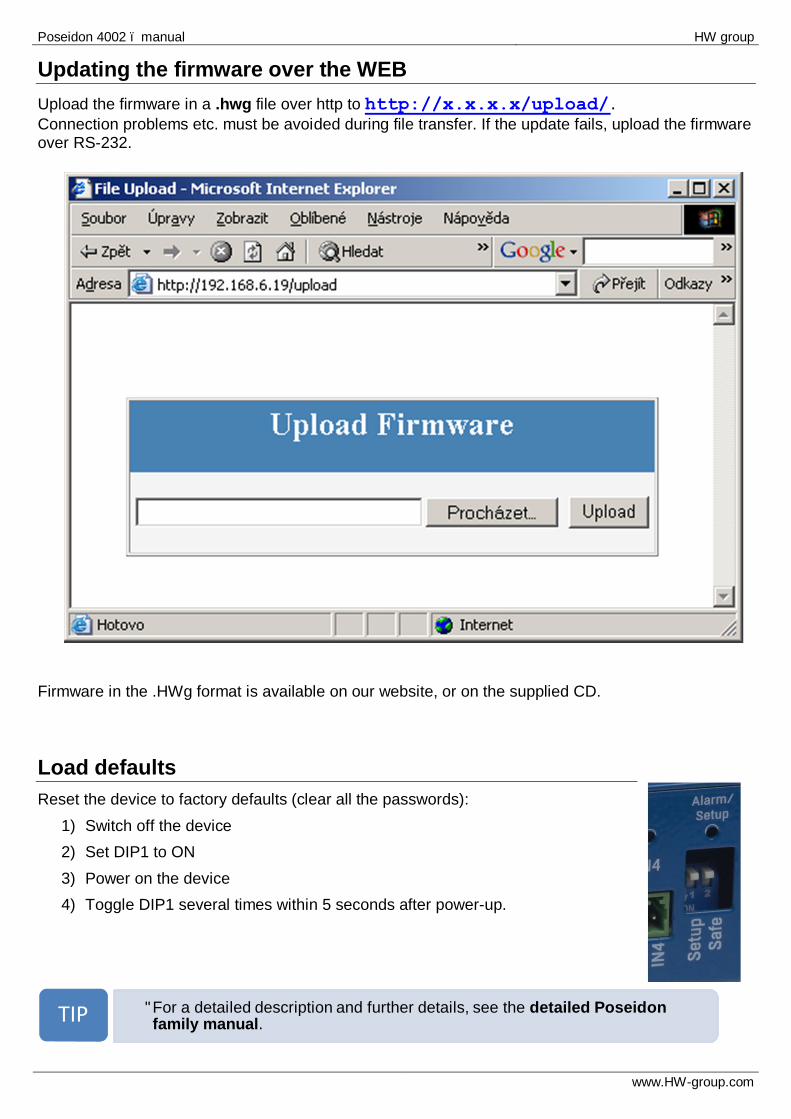
Updating the firmware over the WEB Upload the firmware in a .hwg file over http to http://x.x.x.x/upload/. Connection problems etc. must be avoided during file transfer. If the update fails, upload the firmware over RS-232.
Firmware in the .HWg format is available on our website, or on the supplied CD. Load defaults Reset the device to factory defaults (clear all the passwords):
1) Switch off the device 2) Set DIP1 to ON 3) Power on the device 4) Toggle DIP1 several times within 5 seconds after power-up.
• For a detailed description and further details, see the detailed Poseidon
family manual.TIP