Embed Size (px)
Citation preview
Pattern Recognition Letters 12 (1991) 45-53 January 1991 North-Holland
Pose verification problem
as an optimal assignment
Suchendra M. Bhandarkar*
Dept. of Computer Science, 415 Graduate Studies Research Center, University of Georgia, Athens, GA 30602, USA
Minsoo Suk
Dept. of Electrical and Computer Engineering, 111 Link Hall, Syracuse University, Syracuse, NY 13244-1240, USA
Received 22 October 1990
Abstract
Bhandarkar, S.M. and M. Suk, Pose verification as an optimal assignment problem, Pattern Recognition Letters 12 (1991) 45-53. '
In this paper we propose a feature comparison based technique for pose verification for 3-D object recognition and localization from range images. The proposed technique treats the pose verification problem as an optimal assigmnent problem and could be looked upon as an alternative to the more conventional pose verification technique based on straightforward depth com- parison. As is brought out by the experimental results, the proposed technique shows greater efficiency and robustness as com- pared to the conventional technique. Although the proposed technique is based on dihedral junctions as features for recognition and localization, it could be easily extended to include other feature types.
1. Introduction
Three -d imens iona l ob jec t recogni t ion and locali-
za t ion f rom range images is becoming ext remely
p o p u l a r on account o f the advances in range
imaging technology. The typical s teps in three-
d imens iona l objec t recogni t ion and loca l iza t ion
are preprocess ing , segmenta t ion , fea ture extrac-
t ion, ma tch ing , pose c o m p u t a t i o n , pose hypothesis
genera t ion , pose ver i f ica t ion and scene reconst ruc-
t ion. Issues regarding preprocess ing o f range
* This research was partially supported by U.S. Air Force Grant F30602-85-C-0008 to the Northeast Artificial Intelligence Consortium monitored by the Rome Air Development Center, Rome, NY.
images , segmenta t ion , and fea ture ex t rac t ion have
been well discussed in the l i tera ture . F o r ma tch ing
and pose c o m p u t a t i o n the two p r e d o m i n a n t ap-
p roaches cited in the l i t e ra ture are (i) searching
t h r o u g h an In t e rp re t a t i on Tree and (ii) H o u g h
(Pose) Cluster ing. G r i m s o n [1] and Fauge ras et al.
[2] have used the In t e rp re t a t i on Tree a p p r o a c h
whereas S t o c k m a n [3], Boyter and Agga rwa l [4]
and D h o m e and Kasvand [5] have used the Pose
Clus te r ing a p p r o a c h in their exper iments in three-
d imens iona l ob jec t recogni t ion . The issues re-
ga rd ing pose ver i f ica t ion and scene recons t ruc t ion ,
however , have not been explici t ly addressed . In
this p a p e r we have expl ic i t ly t ack led the p r o b l e m
o f pose ver i f ica t ion . Ear l ie r techniques based on
0167-8655/91/$03.50 © 1991 - - Elsevier Science Publishers B.V. (North-Holland) 45
Volume 12, Number I PATTERN RECOGNITION LETTERS January 1991
straightforward depth comparison such as in the 3-DPO object recognition system [6] were found to be highly unreliable. Small errors in the computed pose lead to large errors in the measured depth. This is particularly true when dealing with mul- tiple-object scenes with partial occlusion. We propose feature-based comparison as an alter- native to straightforward depth comparison. Com- parison of features enables us to treat the problem of pose verification as an optimal assignment problem for which polynomial-time algorithms such as the Hungarian Marriage algorithm are known to exist. Both qualitative and quantitative feature attributes are used in computing an overall match quality for feature comparison. We present experiments on range images of polyhedral ob- jects. The input scenes contain multiple polyhedral objects with objects partially occluding each other. Pose clustering was chosen as the recognition technique on account of its conceptual simplicity and potential ease of parallelization. The advan- tages of feature-based comparison over straight- forward depth comparison are clearly brought out in our experimental results, both in terms of the number of hypotheses tested in order to recon- struct the three-dimensional scene as well as in terms of the number of objects recognized and localized vs. the number of objects missed in the process of 3-D scene reconstruction.
2. Segmentation and feature extraction
Since the input scenes contained polyhedral objects, there were two types of surface disconti- nuities to be considered: (i) Step edges which signify discontinuities in depth and (ii) Roof edges which signify continuity in depth but discontinuity in the surface normal. Roof edges could be further classifed as convex or concave. In our experiment, the step edges were detected using a gradient operator in the x and y directions. The Laplacian operator with averaging was used to detect and localize roof edges. Since the Laplacian operator responds to both step and roof edges, it was diffi- cult to set an appropriate threshold which would detect and localize roof edges accurately. Hence, knowledge of the location of the step edges as
detected by the gradient operator was used to selec- tively suppress the response of the step edges to the Laplacian operator. This enabled the roof edges to be accurately detected and localized using the Laplacian operator. Roof edges were labeled as convex or concave corresponding to the positive or negative maxima respectively, in the output of the Laplacian operator.
Linear boundaries were extracted from the edge points using the 2-D Hough transform in the (~o, 0) space. The output of the boundary extraction process was a list of boundary tokens. Each bound- ary token was represented by a data structure which gave the boundary label, edge type (step, convex roof or concave roof) and the x, y, z co- ordinates of the two endpoints of the boundary. Although the basic line segments forming the boundaries of the objects were detected at this stage, further post-processing was necessary to fill the gaps in the boundary segments and form junction points. The output of the post-processing stage was a list of junction tokens. Furthermore, if a boundary segment terminated at a T type junc- tion, the junction was classified as occluded. Di- hedral junctions, i.e., junctions consisting of a single vertex and two incident edges, were chosen as the features to be used for matching and pose determination. Junctions of order greater than two were decomposed into constituent dihedral junc- tions. Dihedral junctions were considered valid iff they enclosed a visible face on the polyhedral object. Dihedral junctions were checked for validity and those which were not valid were re- jected. For example, T junctions which are highly viewpoint and scene dependent were not con- sidered for purposes of matching and pose com- putation.
3. Feature matching
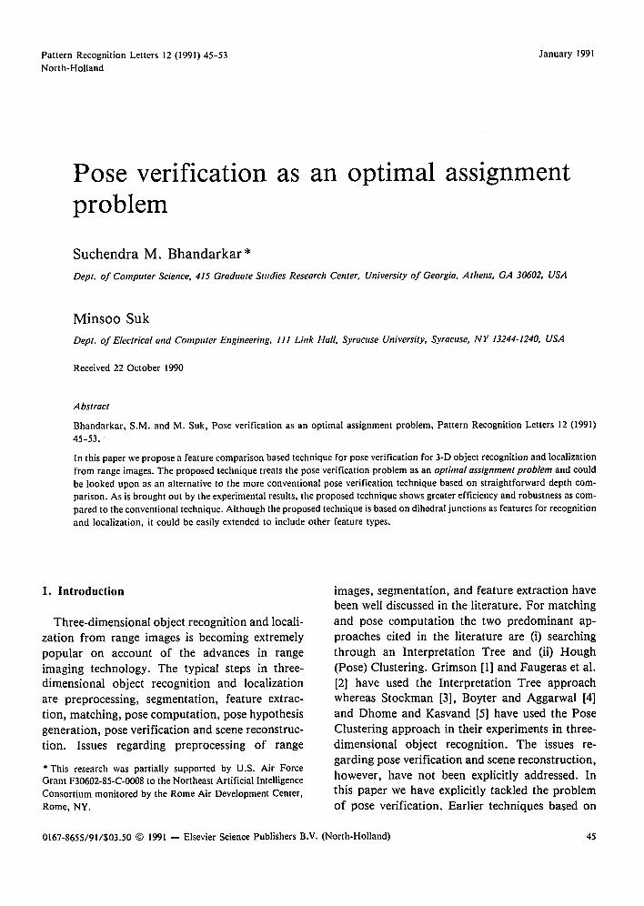
The dihedral junctions extracted from the range image were matched against the dihedral junctions in the object model. Figure 1 shows a candidate scene junction to be matched with a candidate model junction. The match between the candidate scene and model junctions was subjected to a series of tests in which both the qualitative and quanti-
46
Volume 12, Number 1 PATTERN RECOGNITION LETTERS
l n s E ~ F nm J C $1
mt ~ A s2 D
Figure 1. Matching candidate model and scene junctions.
tative feature attributes were used (i) to determine whether a match was acceptable, (ii) for a match that was acceptable, to determine the quality of the match which in our experiment happens to be a numerical measure.
3.1. Angle constraint
M0 = Kl(Omax-IOm- Osl) (l)
where Omax is the maximum allowed deviation in
angle and K l is a constant. Om and Os are the angles enclosed by the model and scene junctions respectively ~(Figure l). I f Mo<O, then the match is rejected else the match quality is incremented by
Mo.
3.2. Length constraint
I f the scene boundary segment is not occluded, then:
ML = K2(Lmax - ILm - Zsl) (2)
where Lma x is the maximum allowed deviation in length and /<2 is a constant. L m and Ls are the lengths of the model and scene edges respectively. I f M L < 0 , then the match is rejected else the match is incremented by M L.
I f the scene boundary segment is occluded and if
L s < L m, then:
ML = K 3 ( Z m - I Z m - Zd). (3)
I f L s < L m, the match is incremented by ML else the match is rejected.
The constants K 2 and K 3 are so chosen that the matches based on unoccluded features have a higher match quality assigned to them as compared to those based on occluded features.
January 1991
4. Pose determination
For a successful match between a scene feature and a model feature the resulting pose was com- puted in terms of a homogeneous coordinate trans- formation. The coordinates (x,y, z) refer to the model coordinate system and (u, o, w) to the scene coordinate system. The operations x and • denote the vector cross product and the vector scalar product respectively.
With reference to Figure 1 let m I be the unit vector in the direction B,4 and m2 be the unit vector in the direction BC. Similarly, let Sl be the unit vector in the direction ED and s2 be the unit vector in the direction EF. The homogeneous coordinates of B in the model coordinate system are given by the column vector [x0, Y0, z0, 1] T and the homogeneous coordinates of E in the scene coordinate system are given by the column vector [Uo, Oo, Wo, I] T. The goal is to find a transfor- mation T such that
T[Xo, Y0, Z0, 1] T = [u0, o0, w0, 1] T. (4)
There is an inherent ambiguity in the matching of the junctions as shown in Figure 1 in the sense that whether m~ should match Sl and m 2 should match s2 or vice versa. The directions of the outward normals n s and n m to the faces bound by the corresponding scene and model junctions, were used to resolve the ambiguity. In Figure I, since
ns=m ~ × m 2 and nm=S 1 ×s2, m I should match s~ and m 2 should match s 2.
The transformation T is determined in a step- wise manner as outlined below [1]:
Step 1. Points B and E are translated to their respective origins. Let T r a n s ( - B) and T r a n s ( - E) denote the respective homogeneous transfor- mations. This ensures that both junctions have their vertices translated to the origin.
Step 2. The vectors m~ and m 2 are rotated about k through an angle 0 so as to end up aligned with sl and s2 respectively, k is determined by the re- quirement that it be perpendicular to both m~-s~ and m 2 - s2 , or equivalently that the projections of m I and sl along k be equal and the projections of m 2 and s 2 along k be equal, i.e.,
47
Volume 12, Number 1 PATTERN RECOGNITION LETTERS January 1991
k . m l = k . S l ~ k . ( m l - s l ) = O ,
k . m 2 = k . s 2 ~ k . ( m 2 - s 2 ) = O .
(5)
(6)
Thus
( m l - s l ) × ( m 2 - s 2 ) k = [(ml _Sl ) × (m2-s2 ) [ . (7)
The angle of rota t ion 0 is determined by [1]:
[mr - ( m l " k ) k ] . [s l - (Sl" k ) k ] cos 0 = (8)
[1 - ( m t • k ) ( s l , k)]
[1 - (m I • Sl) ] = 1 - [1 - ( k . m O ( k "Sl)]" (9)
Step 3. The final t ransformat ion can be thus writ ten as:
Rot(k, 0) Trans( - B)[x0, Y0, z0, 1] r
= Trans( - E)[u0, o0, w0, 1] T. (10)
F rom (4) and (I0)
T = T r a n s - i( _ E) Rot(k, 0) Trans( - B). (11)
The t ransformat ion T f rom the model coordinate system to the scene coordinate system could be thus written as:
T = Rot(k, 0) Trans(t x, ty, tz)
Vrll r12 r13 ! ) [ i 0 0 trill = /r21 r22 r23 1 0 ty (12) ~r~l r32 r33 O1
O 0 O 0
where
rll =k2(1 - c o s 0) + cos 0,
rl2 = kxky(1 - cos 0) - k z sin 0,
r l 3 = kxkz(1 - c o s O) + ky sin O,
r21 =kxky( l - c o s 0) + kz sin 0,
r22 = k2(1 -COS 0) + COS 0,
r23=kykz(l - c o s 0) - kx sin 0,
r3t = kxkz(l - c o s 0 ) - ky sin 0,
r32=kykz(1 - c o s 0) + k.~.sin 0,
r33 = kz2(l - cos 0) + cos 0 (13)
and
tx = Uo - r, ~Xo - rl2Yo - rl3 Zo,
ty = O 0 -- r21x 0 --/'222 0 -- r23 ZO,
tz = Wo-- r31xo -- r32Yo --/'33 ZO. (14)
The axis o f rota t ion k could be alternatively ex- pressed by the pair (~, r/) where
k x = cos ~ sin r/,
ky = sin ~ sin r/,
k z = cos r/ (15)
where - n < r / < n and 0 < ~ < 2 r r .
The t ransformat ion T is thus uniquely specified by the 6-tuple (t~ ty, t z, ~, ~l, 0).
5. P o s e c lus ter ing
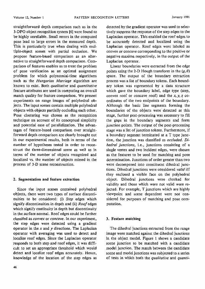
Since using a six-dimensional accumulator array o f reasonable resolution was not feasible in terms o f memory requirement, clustering o f six-dimen- sional feature vectors in Hough space using dis- pari ty matrices was resorted to. A disparity matr ix D was described for each object model as shown in Figure 2. An element Di, j o f the disparity matr ix represents a match between the scene feature i and the model feature j . Di. / equals the geometric t ransformat ion (tx, ty, t z, ~, rl, O) if the match is successful and NIL otherwise. Since we require that each cluster in the Hough space correspond to the occurrence o f a single object f rom a single viewpoint, the following constraints were imposed during the clustering process:
(1) In a given cluster, no scene feature should
Model Features
SCClIC FclllUreS
(x (×
(×
)
Figure 2. Disparity matrix with initial cluster seeds.
48
Volume 12, Number 1 PATTERN RECOGNITION LETTERS January 1991
match more than one model feature. Conflicting matches of a scene feature to more than one model feature are assigned to different clusters.
(2) In a given cluster, no model feature should match more than one scene feature. Conflicting matches of a model feature to more than one scene feature are assigned to different clusters.
In terms of disparity matrices, given two ele- ments Di, ) and Din, n of a single disparity matrix, if either i=m or j = n , the two elements represent conflicting matches in terms of the two constraints described above. It would not have been possible to impose these constraints using an accumulator
array. In order to initiate the clustering process, the
initial seeds were chosen as follows:
(1) A location (i , j) in the disparity matrix where the match quality was a maximum was chosen as a cluster seed.
(2) Locations (non-NIL) in row i and j were chosen as cluster seeds since they are in conflict with the cluster seed chosen in (1).
The clustering process was based on the k-means clustering algorithm [7] where the initial cluster seeds were chosen as the initial values for the k- means. The clustering was done in the six-dimen- sional (t x,ty,tz,~,r/, 0) space. At the end of the clustering process, each cluster mean represents a geometric transform or a pose hypothesis. Each pose hypothesis is also assigned a match quality which is the aggregate of the individual match quality measures of the cluster members.
6. Pose verification
Pose verification is an important aspect of 3-D object recognition which has not been explicitly addressed in the literature. One straightforward technique is that based on direct depth comparison as is mentioned in the 3-DPO object recognition system. The other, which we propose, is one based on feature comparison. As will be brought out in our discussion of the experimental results, the veri- fication technique based on comparison of fea- tures has distinct advantages over the one based on straightforward depth comparison and is also able to alleviate the latter's shortcomings.
6.1. Pose verification by direct depth comparison
Step 1. The pose hypotheses generated by the k- means clustering algorithm are ranked based on a ranking function:
O = K4(Dmax - t 0 + M (16)
where Dm~ x is the depth of the background, M is the quality of the pose hypothesis and K 4 is a con- stant. The ranking function ensures that the hypo- thesis with the least number of occluded features and the least depth (corresponding to the topmost object) is selected first for verification.
Step 2. For the selected pose hypothesis, the corresponding object model is projected on the scene. For each point on the projected object model the corresponding point in the scene is selected for depth comparison. Let dm and d s be the depth values for the point on the projected object model and the corresponding point in the scene respectively. There are three possibilities to be considered:
(a) [dm-ds [ ~<dmax where dma x is the maximum allowable error in depth measurement. In this case the pose hypothesis is in agreement with the scene data within the specified tolerance. This indicates positive evidence for the pose hypothesis. The con- fidencefactor (CF) associated with that particular hypothesis is incremented as follows:
CF:= CF+ K5 (dma. x - lain - dsl) (17)
where K5 is a constant. (b) [dm- dsl > dmax and ds < dm which indicates
that the object in the scene is possibly occluded by another object on top of it. This contributes zero evidence to the pose hypothesis. The confidence factor of the hypothesis is unaltered.
(c) ]dm-ds[>dmax and ds>dm which is strictly speaking a contradiction because it implies that the sensor has seen through the object. This contri- butes negative evidence to the pose hypothesis. The confidence factor of the pose hypothesis is then appropriately decremented:
(ds - dm) CF:= C F - K 6 - (18)
Om~x
where K6 is a constant and Dma.x is the depth of the background.
49
Volume 12, Number I PATTERN RECOGNITION I,H'TEI~,S January 1991
Step 3. If the confidence factor ot" the pose hypothesis exceeds a threshold, then the pose hypothesis is marked as true else it is rejected as false.
Step 4. The next pose hypothesis is considered and Steps I through 3 are repeated until all objects in the scene are verified.
6.2. Pose verification by feature comparison
Step 1. Same as Step 1 i,1 6.1. Step 2. For the selected pose hypothesis, the
corresponding object model is projected onto the scene. A three-dimensional window is defined around the projection. The window serves as a crude filter. If the number of unlabeled scene features in the window is less than the predefined threshold, the hypothesis is rejected.
Step 3. For the hypotheses that pass Step 2, a more detailed comparison based on feature mat- ching is carried out. Each projected model feature is matched to a scene feature within the window. The match is evaluated based on the following criteria:
(a) Proximity. The distance between the junction vertices for the model and scene dihedral junction is computed. A match quality based on this distance is formulated as follows:
M d = KT(dm~,x - d) (19)
where dmttx is the maximum allowed distance and /('7 is a constant. If Md>0, then the total match quality is incremented by Md else the match is rejected.
(b) Angle. The included angles of the model and scene dihedral junctions are compared.
M o = Kg(0m..x - J 0 . , - 0, I) (20)
where Omux is the maximum allowed deviation in angle and Kz is a constant. 0m and 0~ are the angles enclosed by the scene and model junctions respectively. If Mo<O, then the match is rejected else the match quality is updated by Mo.
(c) Orientation. The boundary segments be- longing to the scene and model dihedral junctions are compared with respect to orientation. The difference in orientation is measured in terms of the angle between the boundary junctions.
Me, = Kg(¢~,.ux - ¢~) (21)
where eJ,,,,~ is the maximum allowed deviation in orientation and K 9 iS a constant. If M¢,<O, then the match is rejected else it is updated by M~.
(d) Length. If the scene boundary segment is not occluded, then:
ML = KI0(L,,,,,x - I L,, - L~I) (22)
where L,,,x is the maximum allowed deviation in length and Ki0 is a constanl. L,,, and L s are the lengths of the model and scene edges respectively. If Mr<O, then the match is rejected else the match is incremented by Mr.
If the scene boundary segment is occluded and if L~<L m, then:
Mr. = KII(L,,,- I L,, ,- L,I). (23)
If Ls< L,., the match is incremented by Mr. else the match is rejected.
The constants KH) and Kjl are so chosen that the matches based on unoccluded features have a higher match quality assigned to them as compared to those based on occluded features.
Step 4. For the projected model a match matrix M is defined where the element Mt.j denotes the total match quality between model feature i and scene feature j. Rejected matches have a total match quality of zero. The matrix M need not be square. In cases where the object is occluded in the scene, the number of scene features could be less than the number of model features. The problem therefore is to find an optimum set of pairings of scene and model features which would maximize the total match quality. The pairings should be unique, i.e., no scene feature should be matched to more tha,1 one model feature and no model feature should be matched to more than one scene feature. This is the Optimal Assignment Problem.
Step 5. For a successful pose hypothesis, the corresponding scene features are labeled as be- longing to that particular object model. These scene features are removed from further con- sideration.
Step 6. The remaining features are re-clustered and Steps 1 through 4 are carried out until all the scene features are labeled.
50
Volume 12, Number I I'ATTERN RECO(_}NITION LETTERS
i li!i:iiiil 'i, I, J~ iI ~;
r'
I I ~,
i !!ii " i i1: I~ ~,
*~i:~ ~i '~] ~I~: ?i~:l ...... i li
"ii ? , , i~ '~!Ii::] I'
Jtmuary 1991
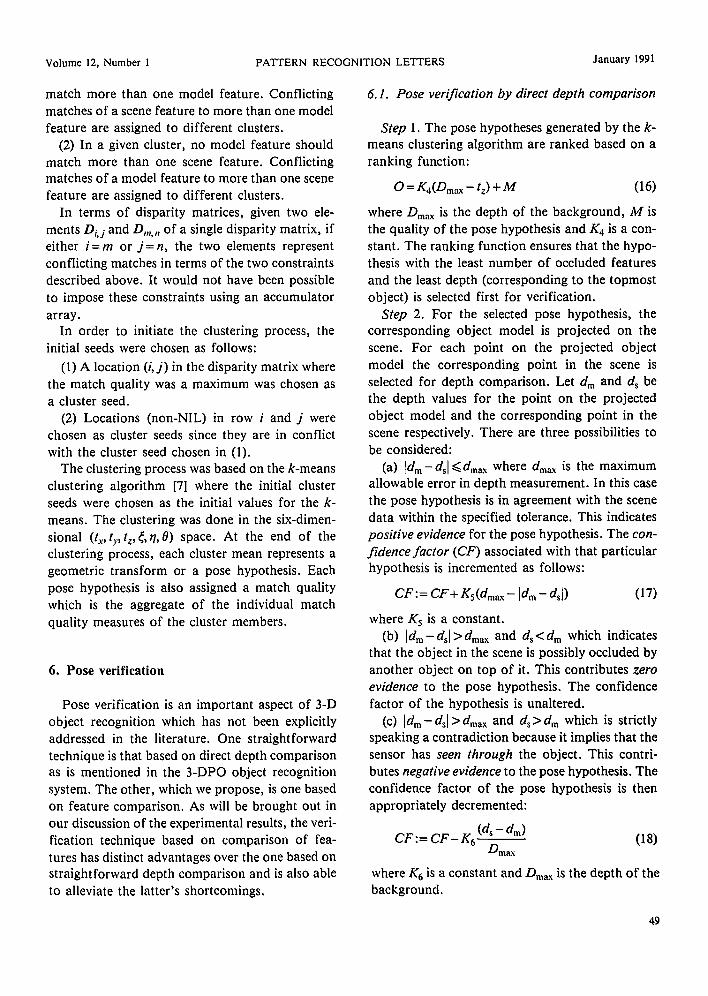
Figure 3. Scene h inpul r~mge hm,gc,
7. Experimenttd resulls
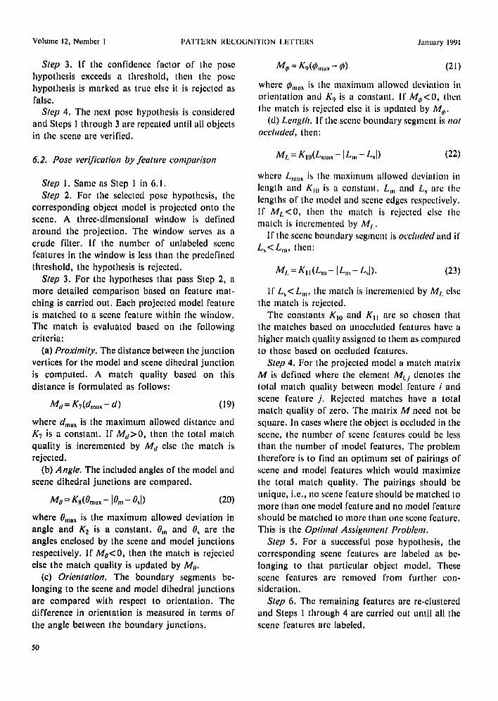
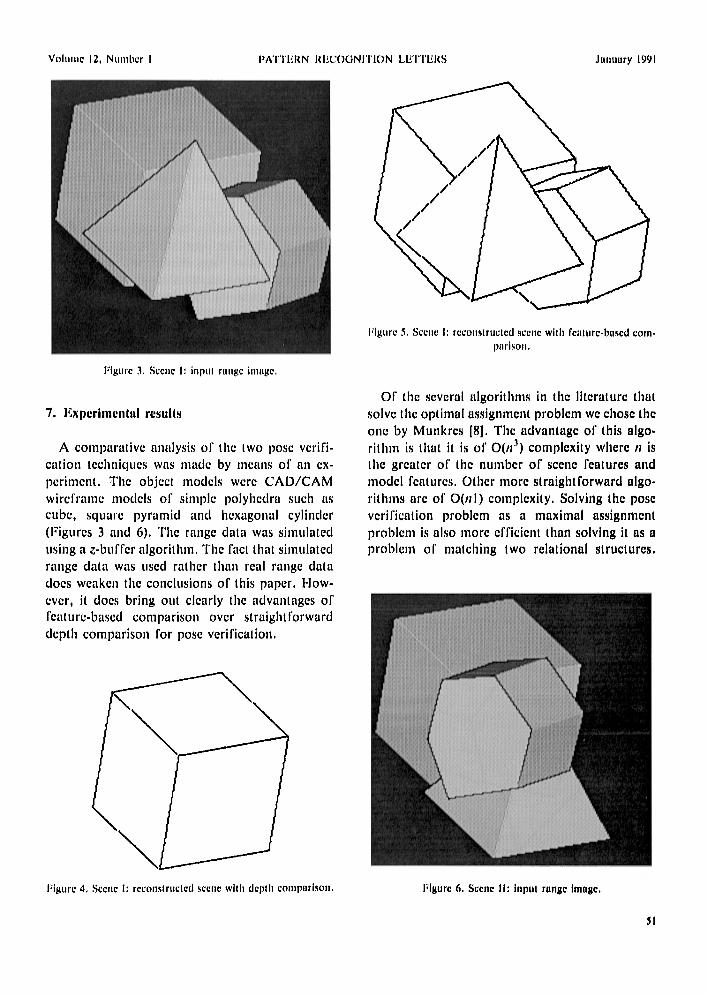
A comparative analysis o1' the two pose verifi- cation techniques was made by means of an ex- periment. The object models were C A D / C A M wireframe models of simple polyhedra such as cube, square pyramid and hexagonal cylinder (Figures 3 and 6). The range data was simulated using a z-buffer algorithm. The fact that simulated range data was used rather than real range data does weake,1 the conclusions of this paper. How- ever, it does bring out clearly the advantages of I'eaturc-based comparison over straightforward depth comparison for pose verification.
I"igure 5, St:cite I: rcconslructcd scene with fcllzure-bused coln- p~lrlson,
Of the several algorithms in the literature that solve the optimal assignment problem we chose the one by Munkres [8]. The advantage of this algo- rithm is that it is of O(n ~) complexity where n is the greater of the number of scene features and model features. Other more straightforward algo- rithms are of O(nl) complexity. Solving the pose verification problem as a maximal assignment problem is also more efficient than solving it as a problem o1" matching two relational structures.
Figure 4, Scene 1: reconstructed scene will] depth conzpllri,~on,
: i ! ' F
ti I ,~i , J,~hlt i J , i !
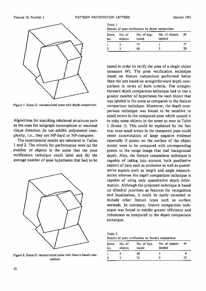
Figure 6. Scene Ii: Inpul runiic Image.
51
Volume 12, Number 1 PATTERN RECOGNITION LETTERS January 1991
\ \
Figure 7. Scene lh reconstructed scene with depth comparison.
Algorithms for matching relational structures such as the ones for subgraph isomorphism or maximal clique detection do not exhibit polynomial com- plexity, i.e., they are NP-hard or NP-complete.
The experimental results are tabulated in Tables 1 and 2. The criteria for performance were (a) the number of objects in the scene that the pose verification technique could label and (b) the average number of pose hypotheses that had to be
Figure 8. Scene Ih reconstructed scene with feature-based com- parison.
Table 1 Results of pose verification by depth comparison
Scene No. of No. of hyp. No. of objects M no. objects tested labeled
1 3 77 1 77
2 3 60 3 20
tested in order to verify the pose of a single object (measure M). The pose verification technique based on feature comparison performed better than the one based on straightforward depth com- parison in terms of both criteria. The straight- forward depth comparison technique had to test a greater number of hypotheses for each object that was labeled in the scene as compared to the feature comparison technique. Moreover, the depth com- parison technique was found t o be sensitive to small errors in the computed pose which caused it to miss some objects in the scene as seen in Table 1 (Scene 1). This could be explained by the fact that even small errors in the computed pose could cause accumulation of large negative evidence especially if points on the surface of the object model were to be compared with corresponding points in the range image that had background depth. Also, the feature comparison technique is capable of taking into account both qualitative aspects of data such as occlusion as well as quanti- tative aspects such as length and angle measure- ments whereas the depth comparison technique is capable of using only quantitative depth infor- mation. Although the proposed technique is based on dihedral junctions as features for recognition and localization, it could be easily extended to include other feature types such as surface normals. In summary, feature comparison tech- nique was found to exhibit greater efficiency and robustness as compared to the depth comparison technique.
Table 2 Results of pose verification by feature comparison
Scene No. of No. of hyp. No. of objects M no. objects tested labeled
1 3 28 3 9 2 3 31 3 10
52
Volume 12, Number 1 PATTERN RECOGNITION LETTERS January 1991
8. Conclusions References
In this paper we have proposed a feature com-
par ison based technique for pose verification for 3-D object recognit ion and localization f rom range images. The proposed technique treats the pose verif ication problem as an opt imal assignment p roblem and could be looked upon as an alter-
native to the more conventional pose verification technique based on s t ra ightforward depth com- parison. As was brought out by the experimental
results, the proposed technique showed greater efficiency and robustness as compared to the
convent ional technique. Al though the proposed technique is based on dihedral junctions as fea- tures for recognit ion and localization, it could be
easily extended to include other feature types.
[I] Grimson, W.E.L. and T. Lozano-Perez (1987). Localizing overlapping parts by searching the interpretation tree. IEEE Trans. Pattern Anal. Machine IntelL 9(4), 469-482.
[2] Faugeras, O.D. and M. Herbert (1986). The representation, recognition and locating of 3-D objects. Int. J. Robotics Research 5(3), 27-52.
[3] Stockman, G. (1987). Object recognition and localization via pose clustering. Computer Vision, Graphics and Image Processing 40, 361-387.
[4] Boyter, B.A. and J.K. Aggarwal (1986). Recognition of polyhedra from range data. IEEE Expert, Spring 1986, 47-59.
[5] Dhome, M. and T. Kasvand 0987). Polyhedra recognition by hypothesis accumulation. IEEE Trans. Pattern Anal. Machine Intell. 9(3), 429-438.
[6] Bolles, R.C. and P. Horaud 0986). 3-DPO: a three- dimensional part orientation system. Int. J. Robotics Research 5(3), 3-25.
[7] Duda, R.O. and P.E. Hart (1972). Pattern ClassO~ication and Scene Analysis. Wiley, New York.
[8] Munkres, J. (1957). Algorithms for the assignment and transportation problems. J. SIAM 5(1), 32-38.
53