Embed Size (px)
Citation preview

4002695-06
575LFK Lift Freestanding Kit
Installation Instructions
CSA approved for use with Valor Models 530I Heaters ONLYIncludes installation instructions for 576LCP and 578LF kits
To complete the installation of this kit you need the following items:• 530I Portrait Engine• 575LFK Lift Freestanding
Kit• 578LF Lift Front• 576LCP Lower Cover
Panel (optional)
Notes: This kit must be installed or serviced by a qualifi ed installer, service agency or gas supplier. These instructions are to be used in conjunction with the main installation instructions for the above listed heater models.The application of this kit does not affect the venting capabilities or method of preparation of the 530 heater as described in the 530 heater installation manual.
INSTALLERLeave this manual with the appliance.
CONSUMERRetain this manual
for future reference.
576LCP—Lower Cover Panel530I—
Portrait Engine
578LF—Lift Front
575LFK—Lift Freestanding Kit (back panel comes with 578 kit)
HOT GLASS WILL CAUSE BURNS.
DO NOT TOUCH GLASS UNTIL COOLED.
NEVER ALLOW CHILDREN TO TOUCH GLASS.
WARNING!
A barrier designed to reduce the risk of burns from the hot viewing glass is provided with this appliance and shall be installed for the protection of children and other at-risk individuals.
PORTRAIT
© Copyright Miles Industries Ltd., 2013
Overview (530I, 575LFK, 576LCP and 578LF sold separately)

2
Basic Installation Sequence• Assemble sides of casing, bottom and top front
brackets.• Assemble bottom brackets to heater.• Fit heater in casing and bolt in place.• Assemble rear brackets to heater and fi x to casing.• Gas fi t and vent heater.• Hook the rear panel, the top panel and infi ll panel.• Install fi rebox grille and complete installation of
heater as per heater installation instructions.• Install bracket and place lower cover panel if used.• Hook window frame cover and front.
Tips• Wear gloves or ensure to manipulate the cast
iron/concrete pieces with clean hands to avoid any stain.
• Remove the 530 window and all items inside the appliance before installing to lighten it.
• In steps 4, 5 and 7 in the following instruc-tions, assemble the parts loosely, just enough for them to hold together. This will allow you to fi t all the parts more easily. Then, in step 10, after all the parts are fi tted together and adjusted, tighten all the screws.
Kits Contents
575LFK Lift Freestanding Kit (required)• Casing left side• Casing right side• Top panel• Top infi ll panel• Convection baffl e• Front hanging bracket• Rear hanging brackets (2)• Bottom support brackets (2)• Engine brackets (2)• Hardware
576LCP Lower Cover Panel (optional)• Lower cover panel• Support bracket• Hardware
578LF Lift Front (required)• Front trim with screen• Window frame cover• Back panel• Firebox grille
Bottom support brackets
Engine brackets
Firebox grille
Convection baffl e
Front hanging bracket
Top panel
Top infi ll panel
Rear hanging brackets
Casing left hand side
Casing right hand side
Back panel
Window frame cover
Front trim
Lower cover panel
Support bracket
3
x
x
x
37-1
5/16
” (96
4 m
m)
29-1
/8” (
739.
7 m
m)
23-11/16” (601.6 mm) 13-5/16”
(338.5 mm)
24-5/8” (625 mm)
B
A
Ceiling
576LCP optionalpanel
36”(914 mm)
min.
See table
14-5
/8” (
371.
5 m
m)
3” (76.2 mm)
min.
4-15/16” (109.5 mm)
Zero clearance
Gas line accesspoint through casing
Gas line accesspoint 8-1/2” (216 mm)
Gas line connection point 3/8” NPT FEMALEat valve
Zero clearance
Sidewall
Mantel
Minimum 53-7/8” (1368.4 mm)
Zero clearanceMin
imum
17-1
/4”
(438
.1 m
m)
Minimum 38” (9
67.3 mm)
Minimum12-1/4”
(311.5 mm)90°
Front View Top ViewRight Side View
Corner Dimensions
Dimensions & Clearances to Combustibles
Mantel Depth ‘A’
0–15”(0–381 mm)
16”(406 mm)
18”(457 mm)
20”(508 mm)
22”(559 mm)
Mantel Height ‘B’
2”(51 mm)
3”(76 mm)
5”(127 mm)
7”(178 mm)
9”(229 mm)
Casting TolerancesDue to the nature of cast iron and concrete, dimen-sional consistency may vary from one unit to the next and some variation in surface fi nish and fl at-ness is to be expected. We have done our best to control and make allowance for this; however some variation is inevitable.
Floor RequirementsThe 530 heater is approved for installation directly on any combustible material other than soft fl ooring material such as carpet or vinyl.
Mobile Home Floor FixingThe Lift FS must be fi xed to the fl oor through the fl oor when used in a mobile home.
Mantel RequirementsThe Lift FS may be installed with a combustible mantel provided clearances are maintained as indicated below. Be aware that although safe, some combustible materials and fi nishes at the listed clearances may, over time, discolor, warp, or show cracks. Care should be taken when choosing materials—consult your fi replace dealer.
Combustible Mantel Clearances
4
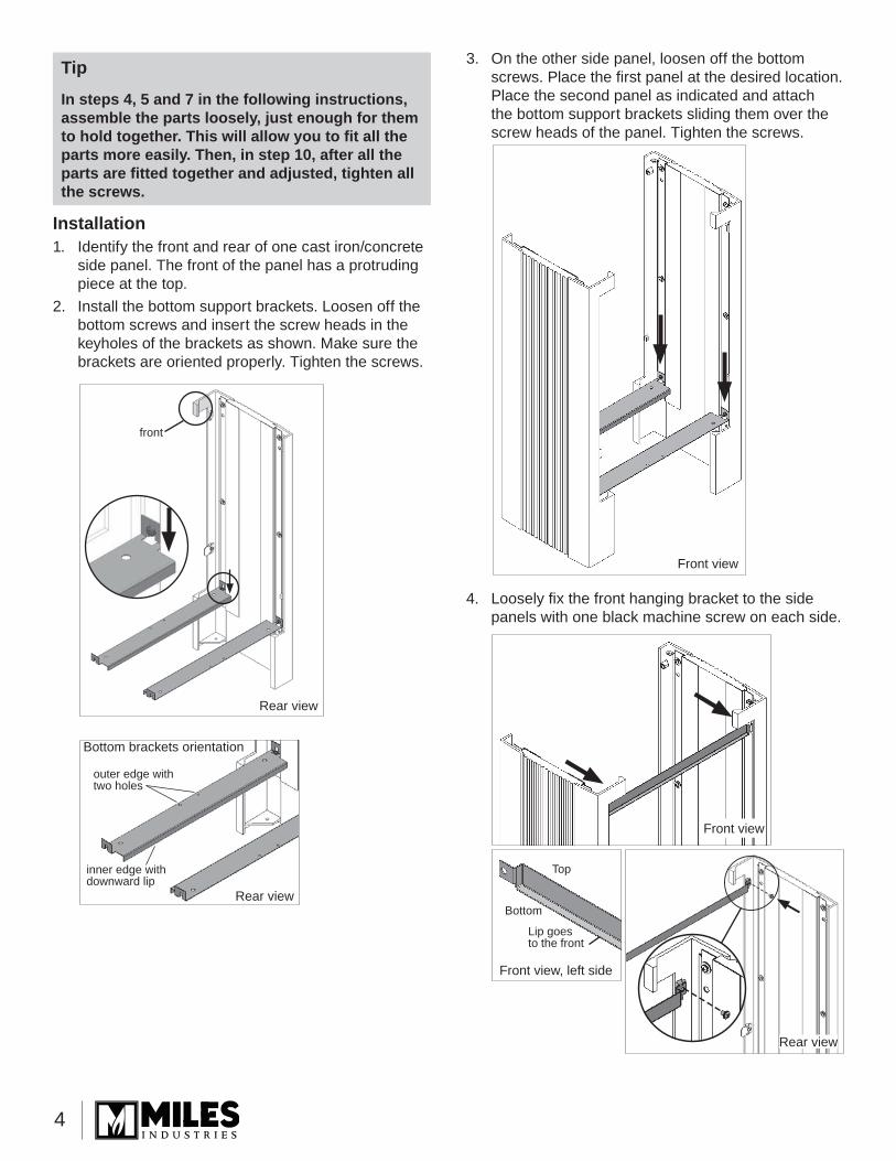
Tip
In steps 4, 5 and 7 in the following instructions, assemble the parts loosely, just enough for them to hold together. This will allow you to fi t all the parts more easily. Then, in step 10, after all the parts are fi tted together and adjusted, tighten all the screws.
Installation1. Identify the front and rear of one cast iron/concrete
side panel. The front of the panel has a protruding piece at the top.
2. Install the bottom support brackets. Loosen off the bottom screws and insert the screw heads in the keyholes of the brackets as shown. Make sure the brackets are oriented properly. Tighten the screws.
front
Rear view
outer edge with two holes
Bottom brackets orientation
inner edge with downward lip
Rear view
Rear view
Front view, left side
Lip goes to the front
Top
Bottom
Front view
Front view
3. On the other side panel, loosen off the bottom screws. Place the fi rst panel at the desired location. Place the second panel as indicated and attach the bottom support brackets sliding them over the screw heads of the panel. Tighten the screws.
4. Loosely fi x the front hanging bracket to the side panels with one black machine screw on each side.

5
5. Fix the engine brackets to the bottom of the appliance with one machine screw on each side as indicated. Either bracket can be used on either side of the appliance.
6. Slide the appliance into the casing from the top. Loosely fi x the appliance to the casing with a nut and bolt on each side at the front and one nut and bolt at the rear left-hand corner.
7. Remove two screws on each side of the back panel of the appliance case. Secure the top rear support brackets to the appliance case using the screws previously removed. Loosely fi x the appliance to the casing with one self-tapping screw per side.
8. Slide the convection baffl e under the top panel of the appliance case. Fix the convection baffl e using two machine screws provided.

6
9. Prepare the heater for venting—top or rear outlet as necessary. Refer to the heater installation manual.Please note that depending on the vent collar location, the casing top and/or back panel must be fi tted over the vent collar. Do not install the vent pipes before you install these panels.
10. Adjust the position of the heater in the casing as necessary. Fit the top panel and tighten all the screws loosely fi tted in steps 4, 6 and 7. Ensure the heater is centered and leveled with the casing. Remove the top panel.
11. Hook the rear panel to the rear hanging brackets. Cut out the knock-out fi rst if rear venting. The rear panel is provided with the 578 kit.
12. Adjust the stove to its fi nal position.13. If necessary, level the stove using the leveling bolts
inside the front legs of the casing.
Grille inserted parallel to
fi rebox edge
14. Fit the top panel of the casing. If necessary, level the top panel using the leveling screws at the top rear corners of the casing. Fit the infi ll panel if rear venting.
15. Install and connect the venting. See the heater installation manual for more information.
16. Remove the window. Connect the gas. See the heater installation manual for more information.
17. 555CFK Circulating Fan Kit. If you are installing a fan kit, we recommend that you proceed now.
18. BEFORE you install the ceramic panels, install the fi rebox top grille provided with the 578 kit as follows:LOGS & ROCKS VERSIONS ONLY. Grille cannot be used with coal fuelbed version. Install the grille panel inside the appliance:a. Insert the grille in the fi rebox by aligning one
of its side edge to the edge of the fi rebox as indicated.
b. Raise the grille up to cover the top fi rebox ports and hold with one hand.Note: The port cover strip supplied with the heater is not required.

7
Window frame cover—rear view
Top
c. Place the rear brick wall. It should support the grille. If not, keep holding it while you place the side brick walls. Refer to the fi replace installation manual for more information on installing the brick walls.
19. Finish the installation of the heater including all the checks necessary for function. Reinstall the window.
20. Hook the window trim cover provided with the 578 kit on the top edge of the window frame.
21. If the 576 optional panel will be used, install it now.a. Fix its support bracket to the bottom front
bracket of the casing using two screws.
b. Slide in the cover panel at a angle to insert it between the casing’s legs. Center it and lean it against its support.
22. Hook the 578 front trim to the casing top front bracket as shown.
Maintenance
Dust down the surface regularly with a soft brush and occasionally follow up with a wipe over with a wet cloth. A sealer has been applied to the surface, no cleaning agents nor polishes should be used. In case of an accidental spill, soak up the liquid IMMEDIATELY with a dry cloth and follow up with a wipe down with a wet cloth.The front steel trim can be cleaned with Windex. To clean the barrier screen, use a soft brush.If the barrier becomes damaged, the barrier shall be replaced with the manufacturer’s barrier for this appliance.To clean the stove glass window, refer to the owner’s manual supplied with the appliance. DO NOT clean with ammonia.
WARNINGDO NOT TOUCH THE BARRIER SCREEN OR DO NOT TOUCH THE BARRIER SCREEN OR STOVE WHILE THEY ARE HOT! STOVE WHILE THEY ARE HOT! Let the stove Let the stove cool first before cleaning it.cool first before cleaning it.FOR SAFETY PURPOSE, ensure the FOR SAFETY PURPOSE, ensure the barrier screen is re-instal led on the barrier screen is re-instal led on the stove front after maintenance.stove front after maintenance.
!

8
Repair Parts List575LFK—Lift Freestanding KitCode Description Part Numbers
1 Top infi ll panel 40020602 Top panel 40020593 Casing left side assembly 40029934 Casing right side assembly 40029925 Left side rear hanging bracket 40029776 Right side rear hanging bracket 40029787 Convection baffl e 4002075BY8 Front hanging bracket 4002964AZ9 Catch (2) 4002688
10 Engine brackets (2) 4002678AZ11 Bottom brackets (2) 4002677AZ
M6 x 18 top leveling screws (2) 4003031Bottom leveling screws (2) 4003021Hardware Kit 4003030
578LFCH—Lift Front CharcoalCode Description Part Numbers
1 Back panel 4002071AZ2 Firebox grille 4002101EB3 Window frame cover 4002279BY4 Heat duct 4002081BY5 LS lead-in 4002693AZ6 RS lead-in 4002692AZ7 Lower lead-in 4002687AZ8 Barrier screen 40034299 Steel trim charcoal 4002691CH
576LCP—Lower Cover PanelCode Description Part Numbers
1 Support Bracket 40029902 Fluted Panel 4002857
Screws 8 x 3/8 (2) 100A757
Designed and Manufactured by / forMiles Industries Ltd.
190 – 2255 Dollarton Highway, North Vancouver, B.C., CANADA V7H 3B1Tel. 604-984-3496 Fax 604-984-0246
www.valorfi replaces.com
Because our policy is one of constant development and improvement, details may vary slightly from those given in this publication.
575LFK 576LCP
578LFCH
1
1
1
2
2
2
3
3
4
4
5
5
6
6
7 7
8
8
9
9
10
11
9
PORTRAIT
© Tous droits réservés, Miles Industries Ltd., 2013
Concept (530I, 575LFK, 576LCP et 578LF sont vendus séparément)
LE PREMIER FOYER À GAZ RADIANT
MC
®
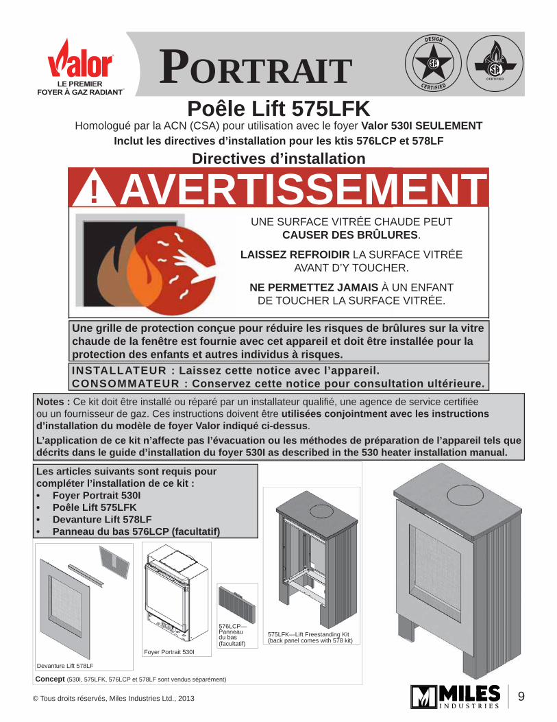
Poêle Lift 575LFK
Directives d’installation
Homologué par la ACN (CSA) pour utilisation avec le foyer Valor 530I SEULEMENTInclut les directives d’installation pour les ktis 576LCP et 578LF
Les articles suivants sont requis pour compléter l’installation de ce kit :• Foyer Portrait 530I• Poêle Lift 575LFK• Devanture Lift 578LF• Panneau du bas 576LCP (facultatif)
Notes : Ce kit doit être installé ou réparé par un installateur qualifi é, une agence de service certifi ée ou un fournisseur de gaz. Ces instructions doivent être utilisées conjointment avec les instructions d’installation du modèle de foyer Valor indiqué ci-dessus.L’application de ce kit n’affecte pas l’évacuation ou les méthodes de préparation de l’appareil tels que décrits dans le guide d’installation du foyer 530I as described in the 530 heater installation manual.
575LFK—Lift Freestanding Kit (back panel comes with 578 kit)
Devanture Lift 578LF
Foyer Portrait 530I
576LCP—Panneau du bas (facultatif)
INSTALLATEUR : Laissez cette notice avec l’appareil. CONSOMMATEUR : Conservez cette notice pour consultation ultérieure.
UNE SURFACE VITRÉE CHAUDE PEUT CAUSER DES BRÛLURES.
LAISSEZ REFROIDIR LA SURFACE VITRÉE AVANT D’Y TOUCHER.
NE PERMETTEZ JAMAIS À UN ENFANT DE TOUCHER LA SURFACE VITRÉE.
AVERTISSEMENT!
Une grille de protection conçue pour réduire les risques de brûlures sur la vitre chaude de la fenêtre est fournie avec cet appareil et doit être installée pour la protection des enfants et autres individus à risques.

10
Conseils• Portez des gants ou assurez-vous de manipuler
les pièces de béton avec les mains propres pour éviter de les tacher.
• Enlevez la fenêtre du foyer de même que tous les morceaux emballés dans sa cavité avant de l’installer afi n de l’alléger.
• Aux étapes 4, 5 et 7 de l’installation, assemblez les pièces sans serrer les vis complètement, les serrant juste assez pour que les pièces tiennent ensemble. Ceci facilitera le montage. Ensuite, à l’étape 10, après avoir fait tous les ajustements nécessaires pour que tout soit d’aplomb, serrez les vis pour solidifi er le montage.
Étapes d’installation• Assemblez les côtés du poêle avec les supports de
montage du bas et la barre de suspension avant.• Assemblez les supports de montage du foyer.• Insérez le foyer dans le casier du poêle.• Assemblez les supports de suspension à l’arrière du
foyer et fi xez-les aux côtés du casier.• Installez l’alimentation de gaz et montez le système
d’évacuation.• Accrochez le panneau arrière et placez le panneau
du dessus et le couvre-évent.• Installez la grille de boîte de foyer et complétez
l’installation selon les directives fournies avec le foyer.
• S’il y a lieu, installez le support du panneau du bas et le panneau.
• Accrochez la bordure de fenêtre et la devanture.
Contenu des kits
Poêle Lift 575LFK (requis)• Côté gauche du poêle• Côté droit du poêle• Panneau du dessus• Couvre-évent• Défl ecteur de convection• Barre de suspension avant• Support de suspension arrière (2)• Supports de montage du bas (2)• Supports du foyer (2)• Quincaillerie
Panneau du bas 576LCP (facultatif)• Panneau• Support• Quincaillerie
Devanture Lift 578LF (requise)• Devanture avec grille de protection• Bordure de fenêtre• Panneau arrière• Grille de boîte de foyer
Supports de montage du bas
Supports du foyer
Grille de boîte de foyer
Défl ecteur de convection
Barre de suspension avant
Panneau du dessusCouvre-évent
Supports de suspension
arrière
Côté gauche du poêle
Côté droit du poêle
Panneau arrière
Bordure de fenêtre
Devanture 578LF
Panneau
Support

11
x
x
x
37-1
5/16
” (96
4 m
m)
29-1
/8” (
739,
7 m
m)
23-11/16” (601,6 mm) 13-5/16”
(338,5 mm)
24-5/8” (625 mm)
B
A
Plafond
Panneaufacultatif576LCP
36”(914 mm)
min.
Voir table
14-5
/8” (
371,
5 m
m)
3” (76,2 mm)
min.
4-15/16” (109,5 mm)
Dégagementzéro
Point d’accès pourconduite de gaz
Point d’accès pour conduite de gaz 8-1/2” (216 mm)
Point de raccord deconduite de gaz à la soupape3/8” NPT FEMELLE
Dégagement zéro
Mur de côté
Manteau
Devant DessusCôté droit
Minimum 53-7/8” (1368,4 mm)
Dégagement zéroMin
imum
17-1
/4”
(438
,1 m
m)
Minimum 38” (9
67,3 mm)
Minimum12-1/4”
(311,5 mm)90°
Dimensions—installation dans un coin
Dimensions et dégagements aux matériaux combustibles
Profondeur ‘A’
0–15”(0–381 mm)
16”(406 mm)
18”(457 mm)
20”(508 mm)
22”(559 mm)
Hauteur ‘B’ 2”(51 mm)
3”(76 mm)
5”(127 mm)
7”(178 mm)
9”(229 mm)
Variations —fonte et bétonDe par leur nature, deux articles de fonte ou de béton fabriqués du même moule peuvent montrer de légères variations dans leurs dimensions et leur fi nition. Nous faisons tout ce qui est possible pour limiter ces variations qui ne peuvent cependant pas être complètement éliminées.
Exigences pour le plancherLe foyer 530 est homologué pour installation directement sur un plancher combustible sauf sur des recouvrements souples comme la moquette ou le vinyle.
Exigences pour installation dans une maison mobileLe poêle Lift doit être fi xé au plancher lorsqu’installé dans une maison mobile.
Exigences pour le manteau de cheminéeLe Lift peut être installé avec un manteau de cheminée combustible à condition de respecter les dégagements indiqués aux schémas ci-dessous. Prenez note que, même en respectant les dégagements requis, certains matériaux combustibles, même s’ils sont sécuritaires, peuvent, avec le temps, se décolorer, se déformer ou craquer. Sélectionnez les matériaux avec soin et consultez votre marchand au besoin.
Dégagements au manteaux combustibles

12
ConseilAux étapes 4, 5 et 7 de l’installation, assemblez les pièces sans serrer les vis complètement, les serrant juste assez pour que les pièces tiennent ensemble. Ceci facilitera le montage. Ensuite, à l’étape 10, après avoir fait tous les ajustements nécessaires pour que tout soit d’aplomb, serrez les vis pour solidifi er le montage.
Installation1. Identifi ez l’avant et l’arrière d’un des côtés du poêle.
Sur l’avant, la fonte forme une saillie en haut du panneau.
2. Installez les supports de montage du bas. Dévissez les vis du bas et insérez les têtes de vis dans la languette des supports tel qu’indiqué. Assurez-vous que les supports sont orientés correctement. Reserrez les vis.
Saillie à l’avant
Vue arrière
2 trous de vis sur le bord extérieur
Orientation des supports
bord intérieur vers le bas
Vue arrière
Vue avant, côté gauche
Rebord en bas à l’avant
Haut
Bas
Vu de l’arrière
Vu de l’avant
Vu de l’avant
3. Sur l’autre côté de poêle, dévissez les vis du bas.Placez le premier côté là où doit être placé le poêle. Assemblez les deux côtés en fi xant les supports de montage du bas au deuxième côté. Resserrez les vis du bas.
4. Assemblez la barre de suspension à l’aide de deux vis à métaux sans toutefois serrer les vis. Le rebord de la barre doit être en bas orienté vers l’avant tel qu’indiqué.

13
5. Fixez les supports de foyer au bas de la caisse du foyer à l’aide d’une vis à métaux de chaque côté tel qu’indiqué. Les supports sont identiques et peuvent être fi xés sur un côté ou l’autre du foyer.
6. Insérez le foyer entre les côtés du poêle tel qu’indiqué. Assemblez le foyer au casier du poêle à l’aide de deux boulons et écrous à l’avant de chaque côté et d’un boulon et écrou au coin arrière gauche. Ne serrez pas les écrous.
7. Enlevez deux vis de chaque côté sur le panneau arrière du foyer. Fixez les supports de suspension arrière au foyer à l’aide de ces deux vis. Fixez ensuite, sans serrer les vis, les supports aux côtés du poêle à l’aide d’une vis par côté tel qu’indiqué.
8. Insérez le défl ecteur de convection sous la paroi de la caisse du foyer. Fixez-le à l’aide de deux vis fournies.

14
9. Préparez le foyer pour l’évacuation—évent dessus ou arrière. Consultez le guide d’installation du foyer pour plus d’information.Veuillez noter que selon le choix de la position de l’évent, la plaque du dessus et/ou le panneau arrière doit être installé par-dessus l’évent. N’installez pas les conduits d’évacuation avant d’installer ces panneaux.
10. Adjustez la position du foyer dans le casier si nécessaire. Placez temporairement le panneau de béton du dessus. Resserrez les vis et boulons des étapes 4, 6 et 7. Enlevez le panneau du dessus.
11. Accrochez le panneau arrière aux supports de suspension arrière. Découpez dabord une ouverture dans le panneau pour l’évent dans le cas d’évacuation à l’arrière. Le panneau arrière est fourni avec la Devanture 578.
12. Finalisez la position du poêle.13. Si nécessaire, nivelez le poêle à l’aide des boulons
de nivelage situés à l’intérieur des pattes avant du poêle.
Grille insérée parallèlement au bord de la boîte de foyer
14. Placez le panneau du dessus. Si nécessaire, nivelez le panneau à l’aide des vis de nivelage situées dans les coins supérieurs arrières du poêle. Placez le couvre-évent si l’évacuation est à l’arrière.
15. Installez et raccordez les conduits d’évacuation. Consultez le guide d’installation du foyer pour plus d’information.
16. Enlevez la fenêtre. Branchez l’alimentation de gaz. Consultez le guide d’installation pour plus d’information.
17. Ventilateur de circulation d’air 555CFK. Si le ventilateur de circulation d’air doit être installé, nous vous conseillons de le faire maintenant.
18. AVANT d’installer les panneaux de céramique, installez la grille de boîte de foyer fournie avec la Devanture 578 :Versions à BÛCHES ET PIERRES SEULEMENT—ne peut être utilisé avec la version charbons.Installez la grille dans la boîte de foyer, couvrant les orifi ces du haut.a. Insérez la grille dans la boîte de foyer en
l’alignant parallèlement au bord de côté de la boîte de foyer tel qu’indiqué.
b. Soulevez la grille contre le panneau supérieur de la boîte de foyer pour couvrir les orifi ces et tenez-la d’une main.Note : le couvercle d’orifi ces fourni avec le foyer n’est pas nécessaire.

15
Bordure de fenêtre—vue de l’arrière
Dessus
c. De l’autre main, placez le muret arrière. La grille devrait reposer sur ce muret. Sinon, continuez de tenir la grille et placez les murets des côtés. Consultez le guide d’installation fourni avec le foyer pour plus d’information.
19. Terminez l’installation du foyer selon les directives du guide d’installation incluant les vérifi cations nécessaires au bon fonctionnement du foyer. Réinstallez la fenêtre.
20. Accrochez la bordure de fenêtre fournie avec la Devanture 578 sur le dessus du cadre de fenêtre.
21. Si le Panneau du bas facultatif 576LCP doit être installé, procédez maintenant.a. Fixez le support du panneau au support du bas
du poêle à l’aide de deux vis.
b. Insérez le panneau derrière les pattes du poêle, centrez-le et appuyez-le sur son support.
22. Accrochez la Devanture 578 à la barre de suspension fi xée au casier du poêle tel qu’indiqué.
Entretien
Époussettez la surface de béton régulièrement avec une brosse à poils souples et de temps à autre, essuyez avec un linge humide.Un scellant a été appliqué sur la surface du béton et aucun produit de nettoyage ou de polissage ne devrait être utilisé sur cette surface. Dans le cas ou un liquide aurait été versé accidentellement, épongez IMMÉDIATEMENT à l’aide d’un linge sec et essuyez ensuite avec un linge humide.La devanture d’acier peut être nettoyée avec du Windex. La grille de protection peut être nettoyée avec une brosse souple.Si la grille est endommagée, elle doit être rem-placée par la grille conçue par le manufacturier pour cet appareil.Pour nettoyer la vitre de la fenêtre, consultez le guide du consommateur fourni avec le foyer. NE PAS netto-yer la vitre avec un produit à base d’ammoniaque.
AVERTISSEMENT!NE TOUCHEZ PAS LA GRILLE DE PROTECTION NE TOUCHEZ PAS LA GRILLE DE PROTECTION OU LE POÊLE LORSQU’ILS SONT CHAUDS! OU LE POÊLE LORSQU’ILS SONT CHAUDS! Laissez le poêle refroidir avant de le nettoyer.Laissez le poêle refroidir avant de le nettoyer.POUR DES RAISONS DE SÉCURITÉ, assurez-POUR DES RAISONS DE SÉCURITÉ, assurez-vous que la grille de protection est réinstallée vous que la grille de protection est réinstallée sur la devanture du poêle après l’entretien.sur la devanture du poêle après l’entretien.

16
Pièces de remplacement575LFK—Poêle LiftCode Description No de pièce
1 Couvre-évent 40020602 Panneau du dessus 40020593 Côté gauche du poêle 40029934 Côté droit du poêle 40029925 Support de suspension gauche 40029776 Support de suspension droit 40029787 Défl ecteur de convection 4002075BY8 Barre de suspension avant 4002964AZ9 Taquets (2) 4002688
10 Supports de foyer (2) 4002678AZ11 Supports de montage du bas (2) 4002677AZ
Vis de nivelage du haut M6 x 18 (2) 4003031Vis de nivealge du bas (2) 4003021Quincaillerie 4003030
578LFCH—Devanture Lift anthraciteCode Description No de pièce
1 Panneau arrière 4002071AZ2 Grille de boîte de foyer 4002101EB3 Bordure de fenêtre 4002279BY4 Canalisation de chaleur 4002081BY5 Panneau intérieur gauche 4002693AZ6 Panneau intérieur droit 4002692AZ7 Panneau intérieur du bas 4002687AZ8 Grille de protection 40034299 Devanture d’acier anthracite 4002691CH
576LCP—Panneau du basCode Description No de pièce
1 Support 40029902 Panneau 4002857
Vis 8 x 3/8 (2) 100A757
575LFK 576LCP
578LFCH
1
1
1
2
2
2
3
3
4
4
5
5
6
6
77
8
89
9
10
11
Conçu et fabriqué par / pourMiles Industries Ltd.
190 – 2255 Dollarton Highway, North Vancouver, BC, CANADA V7H 3B1Tél. 604-984-3496 Téléc. 604-984-0246
www.foyervalor.com
Parce que nous favorisons une politique de développement continu, certains détails de la présente publication peuvent varier.


![INSTALLATION INSTRUCTIONS - Lennox 240009135, Rev. C [06/2012] RETAIN THESE INSTRUCTIONS FOR FUTURE REFERENCE These instructions must be affi xed on or adjacent to the boiler. GAS](https://img.pdfslide.us/doc/110x75/5ab1f3537f8b9ac3348d074a/installation-instructions-lennox-240009135-rev-c-062012-retain-these-instructions.jpg)