Embed Size (px)
Citation preview
www.schneider-electric.comMN
A1M
LSD
M00
EN
, V2.
03, 0
2.20
11
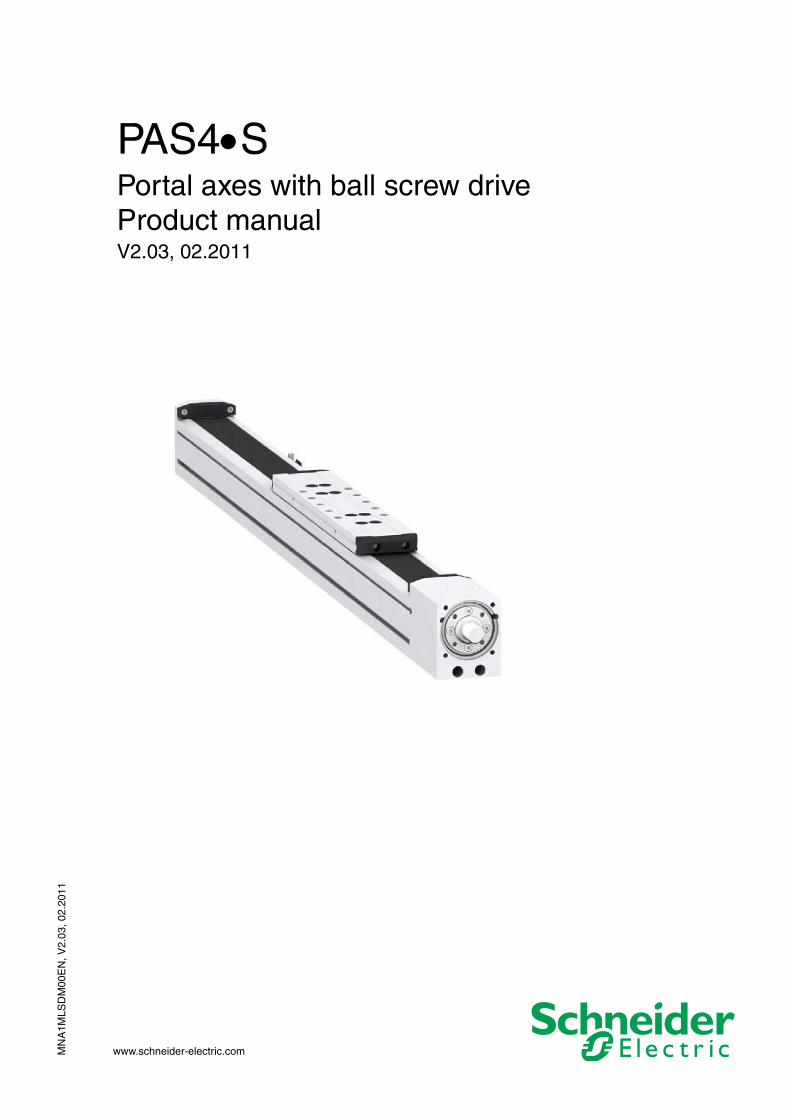
PAS4•SPortal axes with ball screw driveProduct manualV2.03, 02.2011

2 Portal axes with ball screw drive
A Important information PAS4•S
MN
A1M
LSD
M00
EN
, V2.
03, 0
2.20
11
Important information
This manual is part of the product.
Carefully read this manual and observe all instructions.
Keep this manual for future reference.
Hand this manual and all other pertinent product documentation over to all users of the product.
Carefully read and observe all safety instructions and the chapter "Be-fore you begin - safety information".
Some products are not available in all countries.For information on the availability of products, please consult the cata-log.
Subject to technical modifications without notice.
All details provided are technical data which do not constitute warranted qualities.
Most of the product designations are registered trademarks of their re-spective owners, even if this is not explicitly indicated.

MN
A1M
LSD
M00
EN
, V2.
03, 0
2.20
11
PAS4•S B Table of contents
Portal axes with ball screw drive 3
Table of contents
Important information. . . . . . . . . . . . . . . . . . . . . . . . . . . . . . . . . 2
Table of contents . . . . . . . . . . . . . . . . . . . . . . . . . . . . . . . . . . . . 3
Writing conventions and symbols. . . . . . . . . . . . . . . . . . . . . . . 7
1 Introduction . . . . . . . . . . . . . . . . . . . . . . . . . . . . . . . . . . . . . . . . . 9
1.1 Overview of product properties . . . . . . . . . . . . . . . . . . . . 91.1.1 Product family . . . . . . . . . . . . . . . . . . . . . . . . . . . . . . . 91.1.2 Features and options of the linear axis. . . . . . . . . . . . 91.1.3 Characteristics of the linear guide . . . . . . . . . . . . . . . 91.1.4 Motor mounting. . . . . . . . . . . . . . . . . . . . . . . . . . . . . 10
1.2 Product overview. . . . . . . . . . . . . . . . . . . . . . . . . . . . . . 11
1.3 Type code . . . . . . . . . . . . . . . . . . . . . . . . . . . . . . . . . . . 12
1.4 Declaration of Incorporation . . . . . . . . . . . . . . . . . . . . . 16
2 Before you begin - safety information. . . . . . . . . . . . . . . . . . . 17
2.1 Qualification of personnel . . . . . . . . . . . . . . . . . . . . . . . 17
2.2 Intended use . . . . . . . . . . . . . . . . . . . . . . . . . . . . . . . . . 17
2.3 Hazard categories . . . . . . . . . . . . . . . . . . . . . . . . . . . . . 18
2.4 Basic information. . . . . . . . . . . . . . . . . . . . . . . . . . . . . . 19
2.5 Standards and terminology . . . . . . . . . . . . . . . . . . . . . . 20
3 Technical Data . . . . . . . . . . . . . . . . . . . . . . . . . . . . . . . . . . . . . . 21
3.1 Ambient conditions . . . . . . . . . . . . . . . . . . . . . . . . . . . . 21
3.2 PAS42 . . . . . . . . . . . . . . . . . . . . . . . . . . . . . . . . . . . . . . 22
3.3 PAS43 . . . . . . . . . . . . . . . . . . . . . . . . . . . . . . . . . . . . . . 28
3.4 PAS44 . . . . . . . . . . . . . . . . . . . . . . . . . . . . . . . . . . . . . . 34
3.5 Service life. . . . . . . . . . . . . . . . . . . . . . . . . . . . . . . . . . . 40
3.6 Positioning accuracy and repeatability . . . . . . . . . . . . . 40
3.7 Motor . . . . . . . . . . . . . . . . . . . . . . . . . . . . . . . . . . . . . . . 40
4 Portal axes with ball screw drive
B Table of contents PAS4•S
MN
A1M
LSD
M00
EN
, V2.
03, 0
2.20
11
4 Installation. . . . . . . . . . . . . . . . . . . . . . . . . . . . . . . . . . . . . . . . . . 41
4.1 Preparing installation . . . . . . . . . . . . . . . . . . . . . . . . . . 42
4.2 Mechanical installation . . . . . . . . . . . . . . . . . . . . . . . . . 434.2.1 Standard tightening torques. . . . . . . . . . . . . . . . . . . 434.2.2 Mounting the linear axis . . . . . . . . . . . . . . . . . . . . . . 444.2.3 Mounting the contact plate. . . . . . . . . . . . . . . . . . . . 454.2.4 Mounting the sensors. . . . . . . . . . . . . . . . . . . . . . . . 464.2.5 Mounting the motor and the gearbox . . . . . . . . . . . . 484.2.6 Mounting the payload. . . . . . . . . . . . . . . . . . . . . . . . 51
4.3 Electrical installation . . . . . . . . . . . . . . . . . . . . . . . . . . . 524.3.1 Connecting the sensors . . . . . . . . . . . . . . . . . . . . . . 524.3.2 Motor connection . . . . . . . . . . . . . . . . . . . . . . . . . . . 52
4.4 Checking installation. . . . . . . . . . . . . . . . . . . . . . . . . . . 52
5 Commissioning. . . . . . . . . . . . . . . . . . . . . . . . . . . . . . . . . . . . . . 53
5.1 Commissioning procedure . . . . . . . . . . . . . . . . . . . . . . 54
6 Diagnostics and troubleshooting . . . . . . . . . . . . . . . . . . . . . . . 55
6.1 Troubleshooting . . . . . . . . . . . . . . . . . . . . . . . . . . . . . . 55
7 Accessories and spare parts . . . . . . . . . . . . . . . . . . . . . . . . . . 57
7.1 Clamping claws . . . . . . . . . . . . . . . . . . . . . . . . . . . . . . 57
7.2 Slot nuts . . . . . . . . . . . . . . . . . . . . . . . . . . . . . . . . . . . . 58
7.3 Locating dowels . . . . . . . . . . . . . . . . . . . . . . . . . . . . . . 58
7.4 T slot covers . . . . . . . . . . . . . . . . . . . . . . . . . . . . . . . . . 59
7.5 Sensors and additional parts . . . . . . . . . . . . . . . . . . . . 607.5.1 Sensors . . . . . . . . . . . . . . . . . . . . . . . . . . . . . . . . . . 607.5.2 Sensor extension cable . . . . . . . . . . . . . . . . . . . . . . 617.5.3 Sensor holder. . . . . . . . . . . . . . . . . . . . . . . . . . . . . . 617.5.4 Contact plate . . . . . . . . . . . . . . . . . . . . . . . . . . . . . . 61
7.6 Coupling assemblies . . . . . . . . . . . . . . . . . . . . . . . . . . 627.6.1 Elastomer spiders . . . . . . . . . . . . . . . . . . . . . . . . . . 627.6.2 Clamping hubs . . . . . . . . . . . . . . . . . . . . . . . . . . . . . 63
7.7 Grease guns . . . . . . . . . . . . . . . . . . . . . . . . . . . . . . . . . 65
7.8 Cover strips. . . . . . . . . . . . . . . . . . . . . . . . . . . . . . . . . . 65
7.9 Strip deflection . . . . . . . . . . . . . . . . . . . . . . . . . . . . . . . 66
7.10 Cover strip clamp . . . . . . . . . . . . . . . . . . . . . . . . . . . . . 66
7.11 Magnetic strips . . . . . . . . . . . . . . . . . . . . . . . . . . . . . . . 66
7.12 Rubber buffer . . . . . . . . . . . . . . . . . . . . . . . . . . . . . . . . 67

MN
A1M
LSD
M00
EN
, V2.
03, 0
2.20
11
PAS4•S B Table of contents
Portal axes with ball screw drive 5
8 Service, maintenance and disposal . . . . . . . . . . . . . . . . . . . . 69
8.1 Service address . . . . . . . . . . . . . . . . . . . . . . . . . . . . . . 69
8.2 Checks after collisions. . . . . . . . . . . . . . . . . . . . . . . . . . 708.2.1 Ball screw drive . . . . . . . . . . . . . . . . . . . . . . . . . . . . 708.2.2 Ball screw bearing . . . . . . . . . . . . . . . . . . . . . . . . . . 708.2.3 Linear guide . . . . . . . . . . . . . . . . . . . . . . . . . . . . . . . 708.2.4 Elastomer coupling . . . . . . . . . . . . . . . . . . . . . . . . . . 71
8.3 Replacing parts . . . . . . . . . . . . . . . . . . . . . . . . . . . . . . . 728.3.1 Replacing a sensor. . . . . . . . . . . . . . . . . . . . . . . . . . 728.3.2 Replacing the motor or the gearbox . . . . . . . . . . . . . 738.3.3 Replacing the elastomer coupling. . . . . . . . . . . . . . . 758.3.4 Replacing the cover strip and the strip deflection . . . 76
8.4 Maintenance . . . . . . . . . . . . . . . . . . . . . . . . . . . . . . . . . 798.4.1 Cleaning . . . . . . . . . . . . . . . . . . . . . . . . . . . . . . . . . . 798.4.2 Lubrication . . . . . . . . . . . . . . . . . . . . . . . . . . . . . . . . 808.4.3 Lubricating the linear guide and the drive elements . 81
8.5 Shipping, storage, disposal . . . . . . . . . . . . . . . . . . . . . . 82
9 Glossary. . . . . . . . . . . . . . . . . . . . . . . . . . . . . . . . . . . . . . . . . . . 83
9.1 Units and conversion tables . . . . . . . . . . . . . . . . . . . . . 839.1.1 Length. . . . . . . . . . . . . . . . . . . . . . . . . . . . . . . . . . . . 839.1.2 Mass . . . . . . . . . . . . . . . . . . . . . . . . . . . . . . . . . . . . . 839.1.3 Force. . . . . . . . . . . . . . . . . . . . . . . . . . . . . . . . . . . . . 839.1.4 Power . . . . . . . . . . . . . . . . . . . . . . . . . . . . . . . . . . . . 839.1.5 Rotation . . . . . . . . . . . . . . . . . . . . . . . . . . . . . . . . . . 849.1.6 Torque. . . . . . . . . . . . . . . . . . . . . . . . . . . . . . . . . . . . 849.1.7 Moment of inertia . . . . . . . . . . . . . . . . . . . . . . . . . . . 849.1.8 Temperature . . . . . . . . . . . . . . . . . . . . . . . . . . . . . . . 849.1.9 Conductor cross section . . . . . . . . . . . . . . . . . . . . . . 84
9.2 Terms and Abbreviations. . . . . . . . . . . . . . . . . . . . . . . . 85
10 Index. . . . . . . . . . . . . . . . . . . . . . . . . . . . . . . . . . . . . . . . . . . . . . 89

6 Portal axes with ball screw drive
B Table of contents PAS4•S
MN
A1M
LSD
M00
EN
, V2.
03, 0
2.20
11
MN
A1M
LSD
M00
EN
, V2.
03, 0
2.20
11
PAS4•S C Writing conventions and symbols
Portal axes with ball screw drive 7
Writing conventions and symbols
This manual is valid for PAS4xS standard products. Chapter 1 "Introduc-tion" lists the type code for this product. The type code allows you to identify whether your product is a standard product or a customized ver-sion.
The following manuals belong to this product:
• Product manual of the drive, describes the technical data, instal-lation, commissioning and the operating modes and functions.
• Motor manual, describes the technical characteristics of the motors, including correct installation and commissioning.
Source manuals The latest versions of the manuals can be downloaded from the Internet at:
http://www.schneider-electric.com
Source CAD drawings For easier engineering, CAD drawings and product master data are available for download from the Internet at:
http://www.schneider-electric.com
Corrections and suggestions We always try to further optimize our manuals. We welcome your sug-gestions and corrections.
Please get in touch with us by e-mail:[email protected].
Work steps If work steps must be performed consecutively, this sequence of steps is represented as follows:
� Special prerequisites for the following work steps
� Step 1
� Specific response to this work step
� Step 2
If a response to a work step is indicated, this allows you to verify that the work step has been performed correctly.
Unless otherwise stated, the individual steps must be performed in the specified sequence.
Making work easier Information on making work easier is highlighted by this symbol:
Sections highlighted this way provide supplementary information on making work easier.

8 Portal axes with ball screw drive
C Writing conventions and symbols PAS4•S
MN
A1M
LSD
M00
EN
, V2.
03, 0
2.20
11
SI units SI units are the original values. Converted units are shown in brackets behind the original value; they may be rounded.
Example:Minimum conductor cross section: 1.5 mm2 (AWG 14)
Glossary Explanations of special technical terms and abbreviations.
Index List of keywords with references to the corresponding page numbers.

MN
A1M
LSD
M00
EN
, V2.
03, 0
2.20
11
PAS4•S 1 Introduction
Portal axes with ball screw drive 9
11 Introduction
1.1 Overview of product properties
The ball screw axes are based on specially developed and particularly torsion-resistant aluminum profiles. They excel with the their ability to position heavy loads at changing torques with high feed forces and high accuracy.
1.1.1 Product family
The linear axes product family consists of the following sizes:
• PAS42Sx (cross section axis body 60x60 mm)
• PAS43Sx (cross section axis body 80x80 mm)
• PAS44Sx (cross section axis body 110x110 mm)
The sizes differ in terms of outer dimensions, drive data, payload capac-ities and maximum stroke.
1.1.2 Features and options of the linear axis
The linear axis excels with the following features and options:
• High positioning accuracy even at great ballscrew lengths due to several moving ball screw supports
• Easy integration into systems and machines due to axis bodies with T slots
• Different stokes lengths available
• Mounting thread with counterbores for locating dowels at the car-riage for reproducible mounting of the payload
• Grease nipples at the side of the carriage for external lubrication
• Distribution of the payload to up to 3 carriages
• Optional cover strip
• Motor mounting via compact coupling system
• Sensors adjustable in T slots
1.1.3 Characteristics of the linear guide
Recirculating ball bearing guide • High acceleration
• High load capacity
• High accuracy
10 Portal axes with ball screw drive
1 Introduction PAS4•S
MN
A1M
LSD
M00
EN
, V2.
03, 0
2.20
11
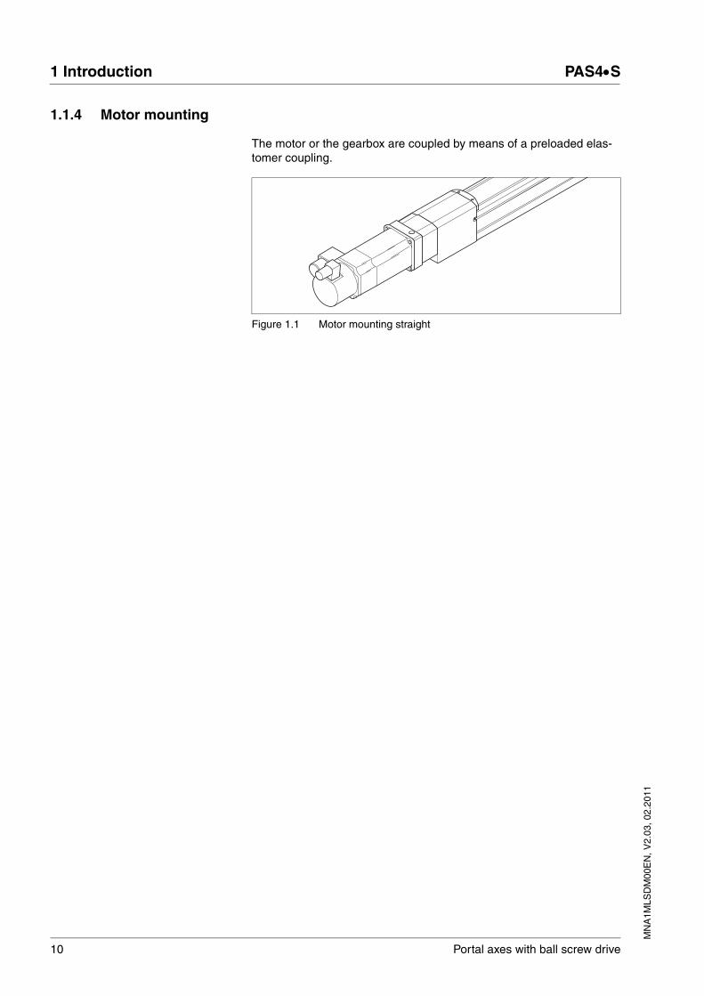
1.1.4 Motor mounting
The motor or the gearbox are coupled by means of a preloaded elas-tomer coupling.
Figure 1.1 Motor mounting straight

MN
A1M
LSD
M00
EN
, V2.
03, 0
2.20
11
PAS4•S 1 Introduction
Portal axes with ball screw drive 11
1.2 Product overview
Figure 1.2 Product overview ball screw axis
(1) Carriage(2) End plate with bearing with ball screw drive(3) Axis body(4) T slot for fastening the axis body(5) Contact plate sensor(6) Grease nipples, 3(7) Sensor holder(8) Sensor with cable and connector(9) T slot for fastening the sensor holder(10) Flange for motor mounting(11) Shaft extension(12) Drive block(13) Clamp fastener for cover strip(14) Cover strip(15) Rubber buffer(16) Strip deflection(17) Thread for fastening the payload
1
2
3
45
6
7
8
9
10
1112
13
1415
1617
12 Portal axes with ball screw drive
1 Introduction PAS4•S
MN
A1M
LSD
M00
EN
, V2.
03, 0
2.20
11
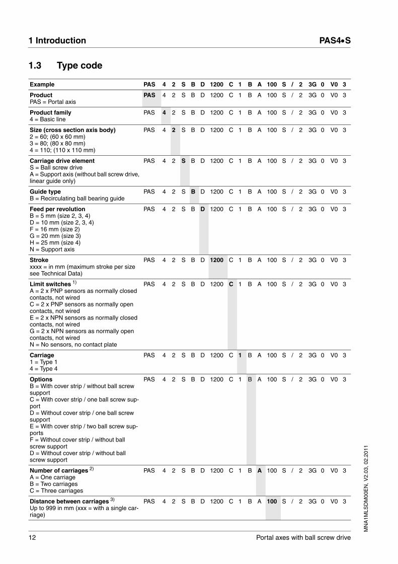
1.3 Type code
Example PAS 4 2 S B D 1200 C 1 B A 100 S / 2 3G 0 V0 3
ProductPAS = Portal axis
PAS 4 2 S B D 1200 C 1 B A 100 S / 2 3G 0 V0 3
Product family4 = Basic line
PAS 4 2 S B D 1200 C 1 B A 100 S / 2 3G 0 V0 3
Size (cross section axis body)2 = 60; (60 x 60 mm)3 = 80; (80 x 80 mm)4 = 110; (110 x 110 mm)
PAS 4 2 S B D 1200 C 1 B A 100 S / 2 3G 0 V0 3
Carriage drive elementS = Ball screw driveA = Support axis (without ball screw drive, linear guide only)
PAS 4 2 S B D 1200 C 1 B A 100 S / 2 3G 0 V0 3
Guide typeB = Recirculating ball bearing guide
PAS 4 2 S B D 1200 C 1 B A 100 S / 2 3G 0 V0 3
Feed per revolutionB = 5 mm (size 2, 3, 4)D = 10 mm (size 2, 3, 4)F = 16 mm (size 2)G = 20 mm (size 3)H = 25 mm (size 4)N = Support axis
PAS 4 2 S B D 1200 C 1 B A 100 S / 2 3G 0 V0 3
Strokexxxx = in mm (maximum stroke per size see Technical Data)
PAS 4 2 S B D 1200 C 1 B A 100 S / 2 3G 0 V0 3
Limit switches 1)
A = 2 x PNP sensors as normally closed contacts, not wiredC = 2 x PNP sensors as normally open contacts, not wiredE = 2 x NPN sensors as normally closed contacts, not wiredG = 2 x NPN sensors as normally open contacts, not wiredN = No sensors, no contact plate
PAS 4 2 S B D 1200 C 1 B A 100 S / 2 3G 0 V0 3
Carriage1 = Type 14 = Type 4
PAS 4 2 S B D 1200 C 1 B A 100 S / 2 3G 0 V0 3
OptionsB = With cover strip / without ball screw supportC = With cover strip / one ball screw sup-portD = Without cover strip / one ball screw supportE = With cover strip / two ball screw sup-portsF = Without cover strip / without ball screw supportD = Without cover strip / without ball screw support
PAS 4 2 S B D 1200 C 1 B A 100 S / 2 3G 0 V0 3
Number of carriages 2)
A = One carriageB = Two carriagesC = Three carriages
PAS 4 2 S B D 1200 C 1 B A 100 S / 2 3G 0 V0 3
Distance between carriages 3)
Up to 999 in mm (xxx = with a single car-riage)
PAS 4 2 S B D 1200 C 1 B A 100 S / 2 3G 0 V0 3

MN
A1M
LSD
M00
EN
, V2.
03, 0
2.20
11
PAS4•S 1 Introduction
Portal axes with ball screw drive 13
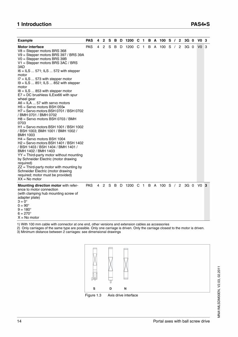
Axis drive interfaceSee Figure 1.3S = With motor mounting or motor adapter mountingD = With shaft extensionN = Support axis
PAS 4 2 S B D 1200 C 1 B A 100 S / 2 3G 0 V0 3
Motor / gearbox interface1 = With motor, without gearbox (select motor type)2 = With motor, with gearbox (select motor/gearbox type)3 = Without motor, with gearbox (select motor/gearbox type)4 = Without motor, without gearbox, with adaptation material (select motor/gearbox type) X = Without motor, without gearbox (with-out select motor/gearbox selection)
PAS 4 2 S B D 1200 C 1 B A 100 S / 2 3G 0 V0 3
Gearbox interface0G = Planetary gear - PLE 401G = Planetary gear - PLE 603G = Planetary gear - PLE 805G = Planetary gear - PLE 1200A = Planetary gear - WPLE 401A = Planetary gear - WPLE 603A = Planetary gear - WPLE 805A = Planetary gear - WPLE 120YY = Third-party gearbox without mount-ing by Schneider Electric (gearbox draw-ing required)ZZ = Third-party gearbox with mounting by Schneider Electric (gearbox must be provided)XX = No gearbox
PAS 4 2 S B D 1200 C 1 B A 100 S / 2 3G 0 V0 3
Mounting direction gearbox(with clamping hub mounting screw of adapter plate)3 = 0°0 = 90°9 = 180°6 = 270°X = No gearbox
PAS 4 2 S B D 1200 C 1 B A 100 S / 2 3G 0 V0 3
Example PAS 4 2 S B D 1200 C 1 B A 100 S / 2 3G 0 V0 3
14 Portal axes with ball screw drive
1 Introduction PAS4•S
MN
A1M
LSD
M00
EN
, V2.
03, 0
2.20
11
Figure 1.3 Axis drive interface
Motor interfaceV8 = Stepper motors BRS 368V9 = Stepper motors BRS 397 / BRS 39AV0 = Stepper motors BRS 39BV1 = Stepper motors BRS 3AC / BRS 3ADI6 = ILS ... 571; ILS ... 572 with stepper motorI7 = ILS ... 573 with stepper motorI9 = ILS ... 851; ILS ... 852 with stepper motorI8 = ILS ... 853 with stepper motorE7 = DC brushless ILExx66 with spur wheel gearA6 = ILA ... 57 with servo motorsH5 = Servo motors BSH 055•H7 = Servo motors BSH 0701 / BSH 0702 / BMH 0701 / BMH 0702H8 = Servo motors BSH 0703 / BMH 0703H1 = Servo motors BSH 1001 / BSH 1002 / BSH 1003; BMH 1001 / BMH 1002 / BMH 1003H4 = Servo motors BSH 1004H2 = Servo motors BSH 1401 / BSH 1402 / BSH 1403 / BSH 1404 / BMH 1401 / BMH 1402 / BMH 1403YY = Third-party motor without mounting by Schneider Electric (motor drawing required)ZZ = Third-party motor with mounting by Schneider Electric (motor drawing required; motor must be provided)XX = No motor
PAS 4 2 S B D 1200 C 1 B A 100 S / 2 3G 0 V0 3
Mounting direction motor with refer-ence to motor connection(with clamping hub mounting screw of adapter plate)3 = 0°0 = 90°9 = 180°6 = 270°X = No motor
PAS 4 2 S B D 1200 C 1 B A 100 S / 2 3G 0 V0 3
1) With 100 mm cable with connector at one end, other versions and extension cables as accessories2) Only carriages of the same type are possible. Only one carriage is driven. Only the carriage closest to the motor is driven.3) Minimum distance between 2 carriages: see dimensional drawings
Example PAS 4 2 S B D 1200 C 1 B A 100 S / 2 3G 0 V0 3
S D N
MN
A1M
LSD
M00
EN
, V2.
03, 0
2.20
11
PAS4•S 1 Introduction
Portal axes with ball screw drive 15
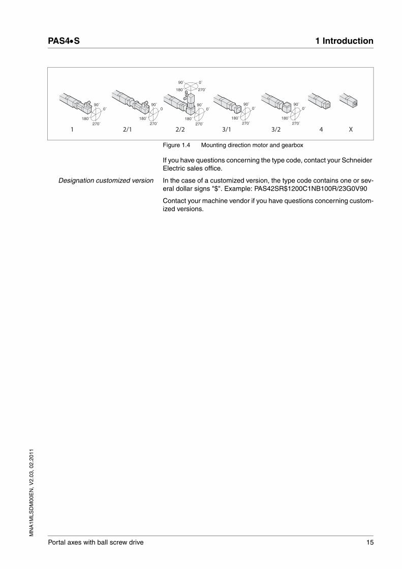
Figure 1.4 Mounting direction motor and gearbox
If you have questions concerning the type code, contact your Schneider Electric sales office.
Designation customized version In the case of a customized version, the type code contains one or sev-eral dollar signs "$". Example: PAS42SR$1200C1NB100R/23G0V90
Contact your machine vendor if you have questions concerning custom-ized versions.
2/1 2/2 3/2 43/1 X1
90˚
270˚180˚
0˚90˚
270˚180˚
090˚
270˚180˚
0˚
90˚
270˚180˚
0˚
90˚
270˚180˚
0˚90˚
270˚180˚
0˚
16 Portal axes with ball screw drive
1 Introduction PAS4•S
MN
A1M
LSD
M00
EN
, V2.
03, 0
2.20
11
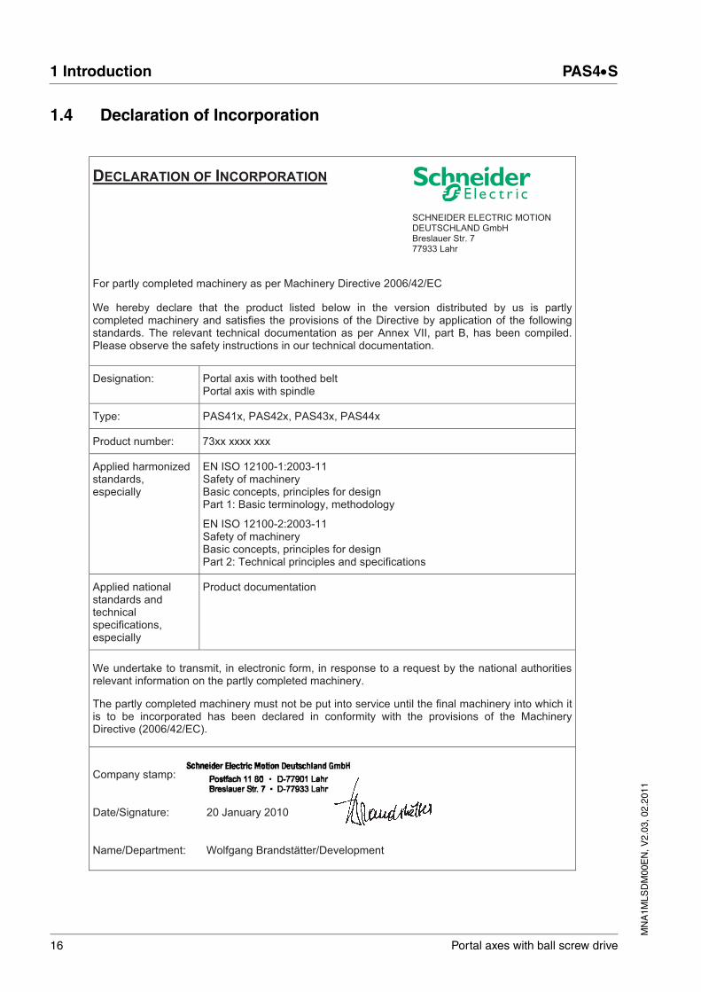
1.4 Declaration of Incorporation
DECLARATION OF INCORPORATION SCHNEIDER ELECTRIC MOTION DEUTSCHLAND GmbH Breslauer Str. 7 77933 Lahr
For partly completed machinery as per Machinery Directive 2006/42/EC
We hereby declare that the product listed below in the version distributed by us is partly completed machinery and satisfies the provisions of the Directive by application of the following standards. The relevant technical documentation as per Annex VII, part B, has been compiled. Please observe the safety instructions in our technical documentation.
Designation: Portal axis with toothed belt Portal axis with spindle
Type: PAS41x, PAS42x, PAS43x, PAS44x
Product number: 73xx xxxx xxx
Applied harmonized standards, especially
EN ISO 12100-1:2003-11 Safety of machinery Basic concepts, principles for design Part 1: Basic terminology, methodology
EN ISO 12100-2:2003-11 Safety of machinery Basic concepts, principles for design Part 2: Technical principles and specifications
Applied national standards and technical specifications, especially
Product documentation
We undertake to transmit, in electronic form, in response to a request by the national authorities relevant information on the partly completed machinery.
The partly completed machinery must not be put into service until the final machinery into which it is to be incorporated has been declared in conformity with the provisions of the Machinery Directive (2006/42/EC).
Company stamp: Date/Signature: 20 January 2010 Name/Department: Wolfgang Brandstätter/Development
MN
A1M
LSD
M00
EN
, V2.
03, 0
2.20
11
PAS4•S 2 Before you begin - safety information
Portal axes with ball screw drive 17
22 Before you begin - safety information
2.1 Qualification of personnel
Only appropriately trained persons who are familiar with and understand the contents of this manual and all other pertinent product documenta-tion are authorized to work on and with this product. In addition, these persons must have received safety training to recognize and avoid haz-ards involved. These persons must have sufficient technical training, knowledge and experience and be able to foresee and detect potential hazards that may be caused by using the product, by changing the set-tings and by the mechanical, electrical and electronic equipment of the entire system in which the product is used.
All persons working on and with the product must be fully familiar with all applicable standards, directives, and accident prevention regulations when performing such work.
2.2 Intended use
This product is a linear axis and intended for industrial use according to this manual.
The product may only be used in compliance with all applicable safety regulations and directives, the specified requirements and the technical data.
Prior to using the product, you must perform a risk assessment in view of the planned application. Based on the results, the appropriate safety measures must be implemented.
Since the product is used as a component in an entire system, you must ensure the safety of persons by means of the design of this entire sys-tem (for example, machine design).
Operate the product only with the specified cables and accessories. Use only genuine accessories and spare parts.
The product must NEVER be operated in explosive atmospheres (haz-ardous locations, Ex areas).
Any use other than the use explicitly permitted is prohibited and can re-sult in hazards.
Electrical equipment should be installed, operated, serviced, and main-tained only by qualified personnel.

18 Portal axes with ball screw drive
2 Before you begin - safety information PAS4•S
MN
A1M
LSD
M00
EN
, V2.
03, 0
2.20
11
2.3 Hazard categories
Safety instructions to the user are highlighted by safety alert symbols in the manual. In addition, labels with symbols and/or instructions are at-tached to the product that alert you to potential hazards.
Depending on the seriousness of the hazard, the safety instructions are divided into 4 hazard categories.
@ DANGER
DANGER indicates an imminently hazardous situation, which, if not avoided, will result in death or serious injury.
@ WARNING
WARNING indicates a potentially hazardous situation, which, if not avoided, can result in death, serious injury, or equipment damage.
@ CAUTION
CAUTION indicates a potentially hazardous situation, which, if not avoided, can result in injury or equipment damage.
CAUTION
CAUTION used without the safety alert symbol, is used to address practices not related to personal injury (e.g. can result in equipment damage).

MN
A1M
LSD
M00
EN
, V2.
03, 0
2.20
11
PAS4•S 2 Before you begin - safety information
Portal axes with ball screw drive 19
2.4 Basic information
@ DANGERELECTRIC SHOCK
High voltages at the motor connection may occur unexpectedly.
• Verify that no voltage is present (this includes the DC bus) prior to taking up work on the drive system.
• AC voltage can couple voltage to unused conductors in the motor cable. Insulate both ends of unused conductors in the motor cable.
• The motor generates voltage when the shaft is rotated. Prior to performing any type of work on the drive system, block the motor shaft to prevent rotation.
Failure to follow these instructions will result in death or serious injury.
@ WARNINGGREAT MASS OR FALLING PARTS
• Consider the mass of the parts when mounting them. It may be necessary to use a crane.
• Mount the parts in such a way (tightening torque, securing screws) that they cannot come loose even in the case of fast acceleration or continuous vibration.
• Take into consideration that axes installed in vertical or tilted posi-tions may move unexpectedly.
Failure to follow these instructions can result in death, serious injury or equipment damage.

20 Portal axes with ball screw drive
2 Before you begin - safety information PAS4•S
MN
A1M
LSD
M00
EN
, V2.
03, 0
2.20
11
2.5 Standards and terminology
Technical terms, terminology and the corresponding descriptions in this manual are intended to use the terms or definitions of the pertinent standards.
In the area of drive systems, this includes, but is not limited to, terms such as "safety function", "safe state", "fault", "fault reset", "failure", "er-ror", "error message", "warning", "warning message", etc.
Among others, these standards include:
• IEC 61800 series: "Adjustable speed electrical power drive sys-tems"
• IEC 61158 series: "Industrial communication networks - Fieldbus specifications"
• IEC 61784 series: "Industrial communication networks - Profiles"
• IEC 61508 series: "Functional safety of electrical/electronic/pro-grammable electronic safety-related systems"
Also see the glossary at the end of this manual.
@ WARNINGLOSS OF CONTROL
• The designer of any control scheme must consider the potential failure modes of control paths and, for certain critical functions, provide a means to achieve a safe state during and after a path failure. Examples of critical control functions are emergency stop, overtravel stop, power outage and restart.
• Separate or redundant control paths must be provided for critical functions.
• System control paths may include communication links. Consid-eration must be given to the implication of unanticipated transmis-sion delays or failures of the link.
• Observe all accident prevention regulations and local safety guidelines. 1)
• Each implementation of the product must be individually and thor-oughly tested for proper operation before being placed into serv-ice.
Failure to follow these instructions can result in death or serious injury.
1) For USA: Additional information, refer to NEMA ICS 1.1 (latest edition), “Safety Guidelines for the Application, Installation, and Maintenance of Solid State Con-trol” and to NEMA ICS 7.1 (latest edition), “Safety Standards for Construction and Guide for Selection, Installation and Operation of Adjustable-Speed Drive Sys-tems”.
MN
A1M
LSD
M00
EN
, V2.
03, 0
2.20
11
PAS4•S 3 Technical Data
Portal axes with ball screw drive 21
33 Technical Data
See chapter 9 "Glossary" for definitions and explanations of terms.
3.1 Ambient conditions
Ambient temperature duringoperation
The following relative humidity is permissible during operation:
Ambient conditions transportationand storage
The environment during transport and storage must be dry and free from dust. The maximum vibration and shock load must be within the speci-fied limits.
Installation altitude
Degree of protection
Vacuum Operation in vacuum is not permissible.
Lubricants and lubrication See chapters 8.4.2 "Lubrication" and 8.4.3 "Lubricating the linear guide and the drive elements".
Temperature [°C] 0 ... +50
Relative humidity As per IEC 60721-3-3, class 3K3, no condensation
Temperature [°C] -25 ... +70
Installation altitude above sea level for linear axis without motor
[m] <1500
Degree of protection IP 20 1)
1) Without cover strip IP00.

22 Portal axes with ball screw drive
3 Technical Data PAS4•S
MN
A1M
LSD
M00
EN
, V2.
03, 0
2.20
11
3.2 PAS42
Value pairs with / without cover strip are separated by "/".
Technical data portal axis PAS42SB
Drive element Ball screw drive (P7 as per DIN 69051 part 3)
Guide type Recirculating ball bearing guide SHS15V
Payload [kg] 25
Carriage type Type 1 Type 4
Carriage length [mm] 323 / 226 503 / 406
Ball screw pitch [mm] 5 10 16 5 10 16
Diameter ball screw shaft [mm] 16
Backlash of the ball screw drive [mm] 0.04
Maximum feed force Fxmax1) [N] 2980 1560 1540 2980 1560 1540
Maximum speed of rotation of ball screw shaft
[min-1] 3000
Maximum velocity 2) [m/s] 0.25 0.50 0.80 0.25 0.50 0.80
Maximum acceleration 2) [m/s2] 2 4 6.4 2 4 6.4
Maximum driving torque Mmax1) [Nm] 3.2 3.3 4.9 3.2 3.3 4.9
Breakaway torque 0 stroke axis 3) [Nm] 0.53 0.56 0.59 0.53 0.56 0.59
Breakaway torque per additional carriage 3)
[Nm] 0.03 0.06 0.09 0.03 0.06 0.09
Moment of inertia 0 stroke axis [kgcm2] 1.21 / 1.16
1.24 / 1.19
1.3/ 1.24 1.29 / 1.25
1.33 / 1.28
1.41 / 1.35
Moment of inertia per additional carriage 3)
[kgcm2] 0.16 / 0.11
0.19 / 0.14
0.25 / 0.19
0.24 / 0.2 0.28 / 0.23
0.36 / 0.3
Moment of inertia per 1 m of stroke [kgcm2/m] 0.35 0.45 0.50 0.35 0.45 0.50
Moment of inertia per 1 kg of payload [kgcm2/kg] 0.006 0.025 0.065 0.006 0.025 0.065
Maximum force Fydynmax1) [N] 4050
Maximum force Fzdynmax1) [N] 4050
Maximum torque Mydynmax1) [Nm] 304 668
Maximum torque Mzdynmax1) [Nm] 304 668
Max. torque Mxdynmax1) [Nm] 27
Mass 0 stroke axis [kg] 6.1 / 5.2 7.8 / 6.9
Mass per additional carriage (with axis body and ball screw drive)
[kg] 3.7 / 2.9 5.5 / 4.6
Mass per 1 m of stroke [kg/m] 6.9
Moving mass carriage [kg] 1.5 / 1.3 2.0 / 1.8
Maximum stroke 4) [mm] 1770 / 1870 1590 / 1690
Minimum stroke 5) [mm] 9
Repeatability 2) [mm] ± 0.02
Diameter motor shaft [mm] 6.35 ... 20
Cross section axis body (W x H) [mm] 60 x 60
Axial area moment of inertia (lx / ly) [mm4] 461960 / 598330
Modulus of elasticity (aluminum) E [N/mm2] 72000
Load rating linear guide Cstat [N] 24200
MN
A1M
LSD
M00
EN
, V2.
03, 0
2.20
11
PAS4•S 3 Technical Data
Portal axes with ball screw drive 23
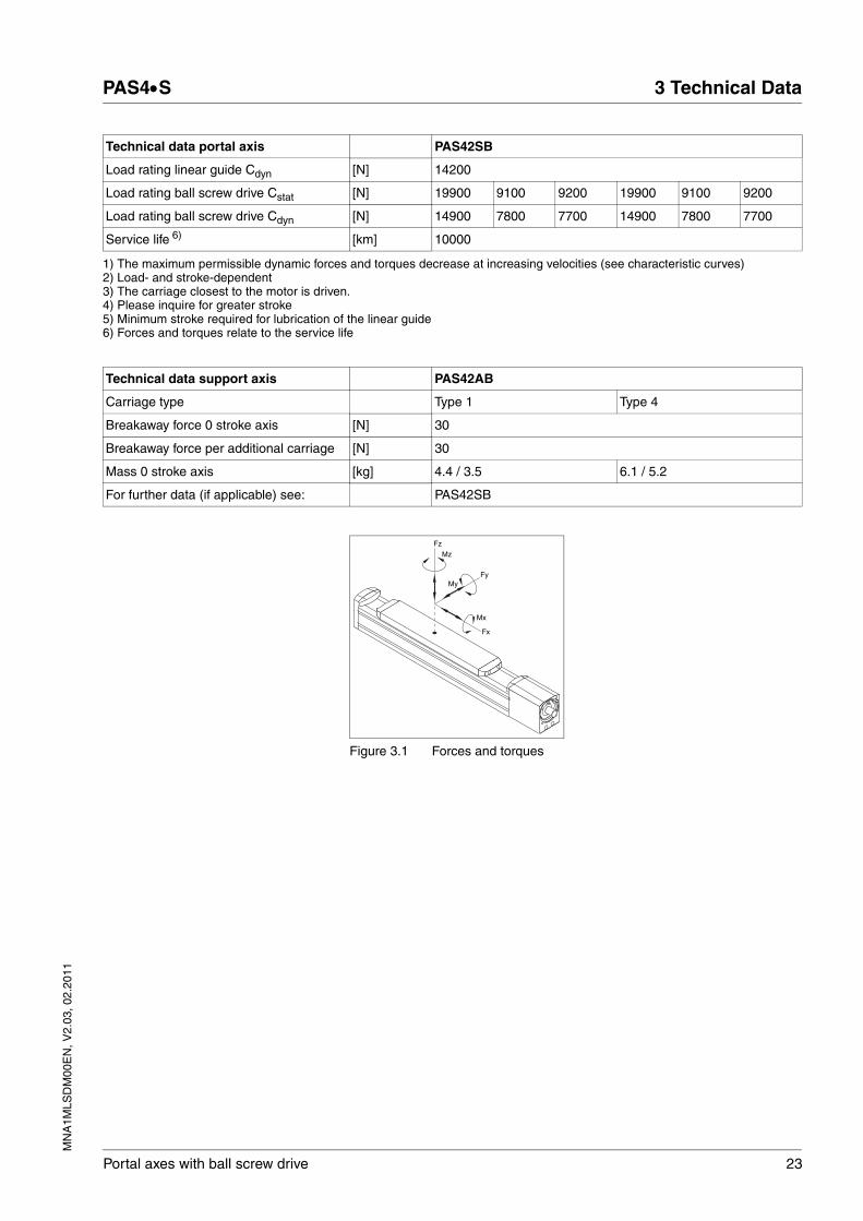
Figure 3.1 Forces and torques
Load rating linear guide Cdyn [N] 14200
Load rating ball screw drive Cstat [N] 19900 9100 9200 19900 9100 9200
Load rating ball screw drive Cdyn [N] 14900 7800 7700 14900 7800 7700
Service life 6) [km] 10000
1) The maximum permissible dynamic forces and torques decrease at increasing velocities (see characteristic curves)2) Load- and stroke-dependent3) The carriage closest to the motor is driven.4) Please inquire for greater stroke5) Minimum stroke required for lubrication of the linear guide6) Forces and torques relate to the service life
Technical data portal axis PAS42SB
Technical data support axis PAS42AB
Carriage type Type 1 Type 4
Breakaway force 0 stroke axis [N] 30
Breakaway force per additional carriage [N] 30
Mass 0 stroke axis [kg] 4.4 / 3.5 6.1 / 5.2
For further data (if applicable) see: PAS42SB
Fz
Mz
FyMy
Fx
Mx

24 Portal axes with ball screw drive
3 Technical Data PAS4•S
MN
A1M
LSD
M00
EN
, V2.
03, 0
2.20
11
Characteristic curves PAS42SB
(1) Carriage type 1(4) Carriage type 4(A,B,C) Ball screw pitch A = 5 mm, B = 10 mm, C = 16 mm
A
B
C
0
500
1000
1500
2000
2500
3000
3500
0 500 1000 1500 2000 2500 3000
n [rpm]
Fx [N]
A
B
C
0
1
2
3
4
5
6
0 500 1000 1500 2000 2500 3000
n [rpm]
M [Nm]
3400
3600
3800
4000
4200
4400
0,0 0,2 0,4 0,6 0,8
v [m/s]
Fydyn [N]
1
4
200
300
400
500
600
700
800
0,0 0,2 0,4 0,6 0,8
v [m/s]
M ydyn [Nm]
3400
3600
3800
4000
4200
4400
0,0 0,2 0,4 0,6 0,8
v [m/s]
Fzdyn [N]
1
4
200
300
400
500
600
700
800
0,0 0,2 0,4 0,6 0,8
v [m/s]
M zdyn [Nm]
0
20000
40000
60000
80000
100000
0,4 0,6 0,8 1,0 1,2 1,4
k
L [km]
22
23
24
25
26
27
28
0,0 0,2 0,4 0,6 0,8
v [m/s]
M xdyn [Nm]
MN
A1M
LSD
M00
EN
, V2.
03, 0
2.20
11
PAS4•S 3 Technical Data
Portal axes with ball screw drive 25
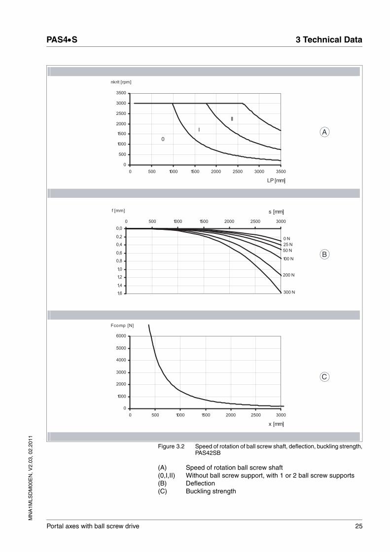
Figure 3.2 Speed of rotation of ball screw shaft, deflection, buckling strength,PAS42SB
(A) Speed of rotation ball screw shaft(0,I,II) Without ball screw support, with 1 or 2 ball screw supports(B) Deflection(C) Buckling strength
0
I
II
0
500
1000
1500
2000
2500
3000
3500
0 500 1000 1500 2000 2500 3000 3500
LP [mm]
nkrit [rpm]
0 N
25 N
50 N
100 N
200 N
300 N
0,0
0,2
0,4
0,6
0,8
1,0
1,2
1,4
1,6
0 500 1000 1500 2000 2500 3000
s [mm]f [mm]
0
1000
2000
3000
4000
5000
6000
0 500 1000 1500 2000 2500 3000
x [mm]
Fcomp [N]
C
B
A

26 Portal axes with ball screw drive
3 Technical Data PAS4•S
MN
A1M
LSD
M00
EN
, V2.
03, 0
2.20
11
Dimensional drawings PAS42SB
Figure 3.3 Dimensional drawing PAS42SB
(1) Portal axis(2) Support axis(3) Shaft extension(4) Drive block(5) Section of axis(6) Carriage type 1 (type 4 has more tapped holes for mounting)
3
A
A
A-A
c LC cX85 d 15dLP
74
E1E0
n x M5 x12n x 8 H7
511.5
1545
75
37.6 40
60
15
2.1
cX 8dLCcd8LS
74
16 g
655
H7
19
20
60
624 x M5 x1245˚
4 x 90
˚
30 30 3030FD D
LC
45±
0.03
59
170
1
2
34
6
5

MN
A1M
LSD
M00
EN
, V2.
03, 0
2.20
11
PAS4•S 3 Technical Data
Portal axes with ball screw drive 27
Carriage type Type 1 Type 4
Cover strip Yes No Yes No
Number of ball screw supports 0, 1 or 2
0 1 2 0, 1 or 2
0 1 2
Total length of portal axis 1) LP [mm] 466 + X
369 + X
399 + X
429 + X
646 + X
549 + X
579 + X
609 + X
Total length of support axis LS [mm] 382 + X
285 + X
315 + X
345 + X
562 + X
465 + X
495 + X
525 + X
Stroke X [mm] See technical data
Carriage length LC [mm] 323 226 503 406
Profile length of carriage F [mm] 190 370
Number of tapped holes for mounting 2) n 10 22
Distance between tapped holes [mm] 30 ±0.03 30 ±0.03
Limit switch position at drive end E0 [mm] 98 50 65 80 98 50 65 80
Limit switch position opposite drive end E1 [mm] 98 50 65 80 278 230 245 260
Stroke reserve up to mechanical stop c [mm] 10 10
Length of cover strip clamp d [mm] 11.5 11.5
Deflection of cover strip D [mm] 48.5 - 48.5 -
Minimum distance between 2 carriages [mm] 90 35 90 35
1) In the case of axes with more than one carriage, you must add the carriage length (LC) and the distance between the carriages for each additional carriage.
2) Prepared for locating rings (see Accessories)

28 Portal axes with ball screw drive
3 Technical Data PAS4•S
MN
A1M
LSD
M00
EN
, V2.
03, 0
2.20
11
3.3 PAS43
Value pairs with / without cover strip are separated by "/".
Technical data portal axis PAS43SB
Drive element Ball screw drive (P7 as per DIN 69051 part 3)
Guide type Recirculating ball bearing guide SHS20
Payload [kg] 60
Carriage type Type 1 Type 4
Carriage length [mm] 394 / 274 604 / 484
Ball screw pitch [mm] 5 10 20 5 10 20
Diameter ball screw shaft [mm] 20
Backlash of the ball screw drive [mm] 0.04
Maximum feed force Fxmax1) [N] 3400 2600 1720 3400 2600 1720
Maximum speed of rotation of ball screw shaft
[min-1] 3000
Maximum velocity 2) [m/s] 0.25 0.50 1.00 0.25 0.50 1.00
Maximum acceleration 2) [m/s2] 2 4 8 2 4 8
Maximum driving torque Mmax1) [Nm] 3.7 5.3 6.8 3.7 5.3 6.8
Breakaway torque 0 stroke axis 3) [Nm] 0.7 0.7 0.8 0.7 0.7 0.8
Breakaway torque per additional carriage 3)
[Nm] 0.04 0.08 0.15 0.04 0.08 0.15
Moment of inertia 0 stroke axis [kgcm2] 2.76 / 2.62
2.82 / 2.67
3.05 / 2.87
2.99 / 2.86
3.07 / 2.93
3.36 / 3.19
Moment of inertia per additional carriage 3)
[kgcm2] 0.46 / 0.32
0.52 / 0.37
0.75 / 0.57
0.69 / 0.56
0.77 / 0.63
1.06 / 0.89
Moment of inertia per 1 m of stroke [kgcm2/m] 0.95 1.10 1.15 0.95 1.10 1.15
Moment of inertia per 1 kg of payload [kgcm2/kg] 0.006 0.025 0.101 0.006 0.025 0.101
Maximum force Fydynmax1) [N] 6360
Maximum force Fzdynmax1) [N] 6360
Maximum torque Mydynmax1) [Nm] 556 1224
Maximum torque Mzdynmax1) [Nm] 556 1224
Max. torque Mxdynmax1) [Nm] 60
Mass 0 stroke axis [kg] 12.1 / 10.3 15.4 / 13.6
Mass per additional carriage (with axis body and ball screw drive)
[kg] 7.7 / 5.9 11.0 / 9.2
Mass per 1 m of stroke [kg/m] 11.70
Moving mass carriage [kg] 3.0 / 2.6 3.9 / 3.5
Maximum stroke 4) [mm] 3070 / 3190 2860 / 2980
Minimum stroke 5) [mm] 11
Repeatability 2) [mm] ± 0.02
Diameter motor shaft [mm] 9 ... 20
Cross section axis body (W x H) [mm] 80 x 80
Axial area moment of inertia (lx / ly) [mm4] 1480060 / 1851160
Modulus of elasticity (aluminum) E [N/mm2] 72000
Load rating linear guide Cstat [N] 38400

MN
A1M
LSD
M00
EN
, V2.
03, 0
2.20
11
PAS4•S 3 Technical Data
Portal axes with ball screw drive 29
Figure 3.4 Forces and torques
Load rating linear guide Cdyn [N] 22300
Load rating ball screw drive Cstat [N] 25300 18400 11600 25300 18400 11600
Load rating ball screw drive Cdyn [N] 17000 13000 8600 17000 13000 8600
Service life 6) [km] 10000
1) The maximum permissible dynamic forces and torques decrease at increasing velocities (see characteristic curves)2) Load- and stroke-dependent3) The carriage closest to the motor is driven.4) Please inquire for greater stroke5) Minimum stroke required for lubrication of the linear guide6) Forces and torques relate to the service life
Technical data portal axis PAS43SB
Technical data support axis PAS43AB
Carriage type Type 1 Type 4
Breakaway force 0 stroke axis [N] 40
Breakaway force per additional carriage [N] 40
Mass 0 stroke axis [kg] 9.1 / 7.3 12.4 / 10.6
For further data (if applicable) see: PAS43SB
Fz
Mz
FyMy
Fx
Mx

30 Portal axes with ball screw drive
3 Technical Data PAS4•S
MN
A1M
LSD
M00
EN
, V2.
03, 0
2.20
11
Characteristic curves PAS43SB
(1) Carriage type 1(4) Carriage type 4(A,B,C) Ball screw pitch A = 5 mm, B = 10 mm, C = 20 mm
A
B
C
500
1000
1500
2000
2500
3000
3500
4000
0 500 1000 1500 2000 2500 3000
n [rpm]
Fx [N]
A
B
C
2
3
4
5
6
7
0 500 1000 1500 2000 2500 3000
n [rpm]
M [Nm]
5200
5400
5600
5800
6000
6200
6400
6600
0,0 0,2 0,4 0,6 0,8 1,0
v [m/s]
Fydyn [N]
1
4
200
400
600
800
1000
1200
1400
0,0 0,2 0,4 0,6 0,8 1,0
v [m/s]
M ydyn [Nm]
5200
5400
5600
5800
6000
6200
6400
6600
0,0 0,2 0,4 0,6 0,8 1,0
v [m/s]
Fzdyn [N]
1
4
200
400
600
800
1000
1200
1400
0,0 0,2 0,4 0,6 0,8 1,0
v [m/s]
M zdyn [Nm]
0
20000
40000
60000
80000
100000
0,4 0,6 0,8 1,0 1,2 1,4
k
L [km]
48
50
52
54
56
58
60
62
0,0 0,2 0,4 0,6 0,8 1,0
v [m/s]
M xdyn [Nm]

MN
A1M
LSD
M00
EN
, V2.
03, 0
2.20
11
PAS4•S 3 Technical Data
Portal axes with ball screw drive 31
Figure 3.5 Speed of rotation of ball screw shaft, deflection, buckling strength,PAS43SB
(A) Speed of rotation ball screw shaft(0,I,II) Without ball screw support, with 1 or 2 ball screw supports(B) Deflection(C) Buckling strength
0
I
II
0
500
1000
1500
2000
2500
3000
3500
0 500 1000 1500 2000 2500 3000 3500 4000
LP [mm]
nkrit [rpm]
0 N
50 N100 N
200 N
400 N
800 N
0,0
0,2
0,4
0,6
0,8
1,0
1,2
1,4
0 500 1000 1500 2000 2500 3000
s [mm]f [mm]
0
1000
2000
3000
4000
5000
6000
7000
0 500 1000 1500 2000 2500 3000 3500
x [mm]
Fcomp [N]
C
B
A

32 Portal axes with ball screw drive
3 Technical Data PAS4•S
MN
A1M
LSD
M00
EN
, V2.
03, 0
2.20
11
Dimensional drawings PAS43SB
Figure 3.6 Dimensional drawing PAS43SB
(1) Portal axis(2) Support axis(3) Shaft extension(4) Drive block(5) Section of axis(6) Carriage type 1 (type 4 has more tapped holes for mounting)
A
A
A-A
c cX95
99
d LC 20d
E1E0
LP
6.2
16.3
2065
100
4.5
11.25 5080
2.1
n x M6 x14n x 10 H7
15
cXc10
99
d LC 10dLS
LCD
35 35 35 35F D
79
60±
0.03
170
20 g
6
75 H
7
23 3
22 80
45˚
4 x 9
0˚ 4 x M6 x1283
1
2
3 4
6
5

MN
A1M
LSD
M00
EN
, V2.
03, 0
2.20
11
PAS4•S 3 Technical Data
Portal axes with ball screw drive 33
Carriage type Type 1 Type 4
Cover strip Yes No Yes No
Number of ball screw supports 0, 1 or 2
0 1 2 0, 1 or 2
0 1 2
Total length of portal axis 1) LP [mm] 569 + X
449 + X
489 + X
529 + X
779 + X
659 + X
699 + X
739 + X
Total length of support axis LS [mm] 474 + X
354 + X
394 + X
434 + X
684 + X
564 + X
604 + X
644 + X
Stroke X [mm] See technical data
Carriage length LC [mm] 394 274 604 484
Profile length of carriage F [mm] 230 440
Number of tapped holes for mounting 2) n 10 22
Distance between tapped holes [mm] 35 ±0.03 35 ±0.03
Limit switch position at drive end E0 [mm] 143 83 103 123 143 83 103 123
Limit switch position opposite drive end E1 [mm] 143 83 103 123 353 293 313 333
Stroke reserve up to mechanical stop c [mm] 15 15
Length of cover strip clamp d [mm] 15 15
Deflection of cover strip D [mm] 60 - 60 -
Minimum distance between 2 carriages [mm] 90 35 90 35
1) In the case of axes with more than one carriage, you must add the carriage length (LC) and the distance between the carriages for each additional carriage.
2) Prepared for locating rings (see Accessories)
34 Portal axes with ball screw drive
3 Technical Data PAS4•S
MN
A1M
LSD
M00
EN
, V2.
03, 0
2.20
11
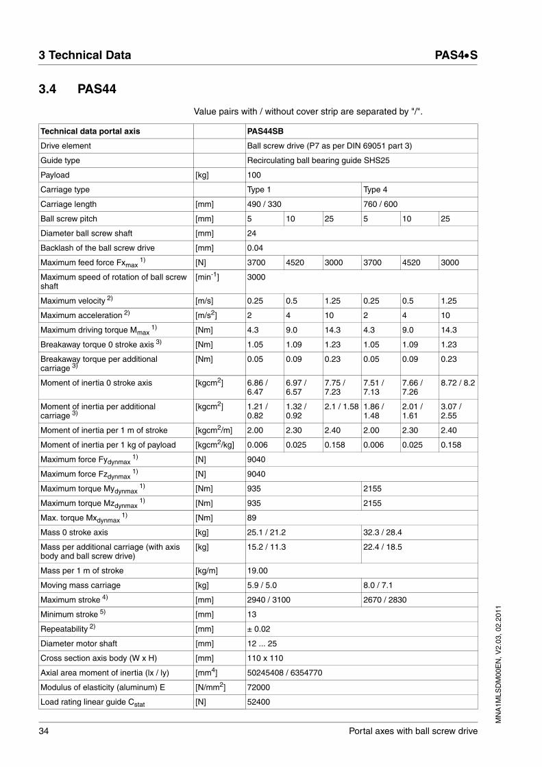
3.4 PAS44
Value pairs with / without cover strip are separated by "/".
Technical data portal axis PAS44SB
Drive element Ball screw drive (P7 as per DIN 69051 part 3)
Guide type Recirculating ball bearing guide SHS25
Payload [kg] 100
Carriage type Type 1 Type 4
Carriage length [mm] 490 / 330 760 / 600
Ball screw pitch [mm] 5 10 25 5 10 25
Diameter ball screw shaft [mm] 24
Backlash of the ball screw drive [mm] 0.04
Maximum feed force Fxmax1) [N] 3700 4520 3000 3700 4520 3000
Maximum speed of rotation of ball screw shaft
[min-1] 3000
Maximum velocity 2) [m/s] 0.25 0.5 1.25 0.25 0.5 1.25
Maximum acceleration 2) [m/s2] 2 4 10 2 4 10
Maximum driving torque Mmax1) [Nm] 4.3 9.0 14.3 4.3 9.0 14.3
Breakaway torque 0 stroke axis 3) [Nm] 1.05 1.09 1.23 1.05 1.09 1.23
Breakaway torque per additional carriage 3)
[Nm] 0.05 0.09 0.23 0.05 0.09 0.23
Moment of inertia 0 stroke axis [kgcm2] 6.86 / 6.47
6.97 / 6.57
7.75 / 7.23
7.51 / 7.13
7.66 / 7.26
8.72 / 8.2
Moment of inertia per additional carriage 3)
[kgcm2] 1.21 / 0.82
1.32 / 0.92
2.1 / 1.58 1.86 /1.48
2.01 / 1.61
3.07 / 2.55
Moment of inertia per 1 m of stroke [kgcm2/m] 2.00 2.30 2.40 2.00 2.30 2.40
Moment of inertia per 1 kg of payload [kgcm2/kg] 0.006 0.025 0.158 0.006 0.025 0.158
Maximum force Fydynmax1) [N] 9040
Maximum force Fzdynmax1) [N] 9040
Maximum torque Mydynmax1) [Nm] 935 2155
Maximum torque Mzdynmax1) [Nm] 935 2155
Max. torque Mxdynmax1) [Nm] 89
Mass 0 stroke axis [kg] 25.1 / 21.2 32.3 / 28.4
Mass per additional carriage (with axis body and ball screw drive)
[kg] 15.2 / 11.3 22.4 / 18.5
Mass per 1 m of stroke [kg/m] 19.00
Moving mass carriage [kg] 5.9 / 5.0 8.0 / 7.1
Maximum stroke 4) [mm] 2940 / 3100 2670 / 2830
Minimum stroke 5) [mm] 13
Repeatability 2) [mm] ± 0.02
Diameter motor shaft [mm] 12 ... 25
Cross section axis body (W x H) [mm] 110 x 110
Axial area moment of inertia (lx / ly) [mm4] 50245408 / 6354770
Modulus of elasticity (aluminum) E [N/mm2] 72000
Load rating linear guide Cstat [N] 52400

MN
A1M
LSD
M00
EN
, V2.
03, 0
2.20
11
PAS4•S 3 Technical Data
Portal axes with ball screw drive 35
Figure 3.7 Forces and torques
Load rating linear guide Cdyn [N] 31700
Load rating ball screw drive Cstat [N] 30400 31400 19900 30400 31400 19900
Load rating ball screw drive Cdyn [N] 18500 22600 15000 18500 22600 15000
Service life 6) [km] 10000
1) The maximum permissible dynamic forces and torques decrease at increasing velocities (see characteristic curves)2) Load- and stroke-dependent3) The carriage closest to the motor is driven.4) Please inquire for greater stroke5) Minimum stroke required for lubrication of the linear guide6) Forces and torques relate to the service life
Technical data portal axis PAS44SB
Technical data support axis PAS44AB
Carriage type Type 1 Type 4
Breakaway force 0 stroke axis [N] 50
Breakaway force per additional carriage [N] 50
Mass 0 stroke axis [kg] 18.7 / 14.8 25.9 / 22.0
For further data (if applicable) see: PAS44SB
Fz
Mz
FyMy
Fx
Mx
36 Portal axes with ball screw drive
3 Technical Data PAS4•S
MN
A1M
LSD
M00
EN
, V2.
03, 0
2.20
11
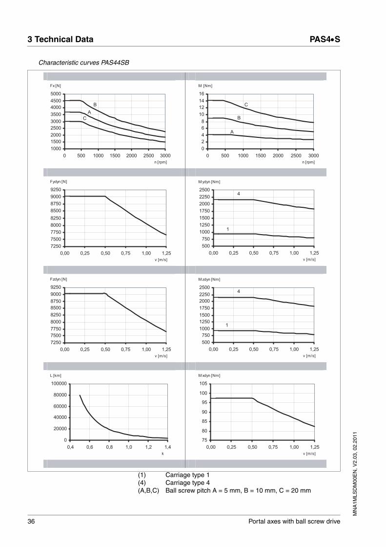
Characteristic curves PAS44SB
(1) Carriage type 1(4) Carriage type 4(A,B,C) Ball screw pitch A = 5 mm, B = 10 mm, C = 20 mm
A
B
C
1000
1500
2000
2500
3000
3500
4000
4500
5000
0 500 1000 1500 2000 2500 3000
n [rpm]
Fx [N]
A
B
C
0
2
4
6
8
10
12
14
16
0 500 1000 1500 2000 2500 3000
n [rpm]
M [Nm]
7250
7500
7750
8000
8250
8500
8750
9000
9250
0,00 0,25 0,50 0,75 1,00 1,25
v [m/s]
Fydyn [N]
1
4
500
750
1000
1250
1500
1750
2000
2250
2500
0,00 0,25 0,50 0,75 1,00 1,25
v [m/s]
M ydyn [Nm]
7250
7500
7750
8000
8250
8500
8750
9000
9250
0,00 0,25 0,50 0,75 1,00 1,25
v [m/s]
Fzdyn [N]
1
4
500
750
1000
1250
1500
1750
2000
2250
2500
0,00 0,25 0,50 0,75 1,00 1,25
v [m/s]
M zdyn [Nm]
0
20000
40000
60000
80000
100000
0,4 0,6 0,8 1,0 1,2 1,4
k
L [km]
75
80
85
90
95
100
105
0,00 0,25 0,50 0,75 1,00 1,25
v [m/s]
M xdyn [Nm]
MN
A1M
LSD
M00
EN
, V2.
03, 0
2.20
11
PAS4•S 3 Technical Data
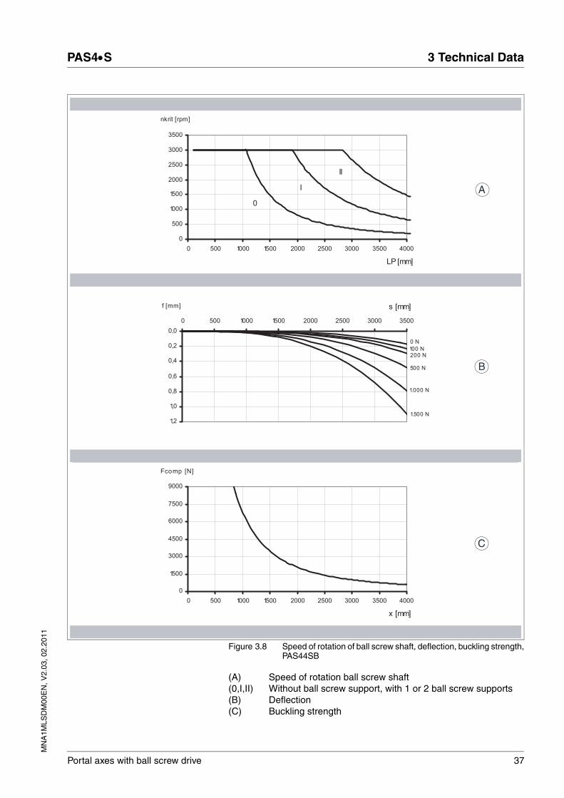
Portal axes with ball screw drive 37
Figure 3.8 Speed of rotation of ball screw shaft, deflection, buckling strength,PAS44SB
(A) Speed of rotation ball screw shaft(0,I,II) Without ball screw support, with 1 or 2 ball screw supports(B) Deflection(C) Buckling strength
0
I
II
0
500
1000
1500
2000
2500
3000
3500
0 500 1000 1500 2000 2500 3000 3500 4000
LP [mm]
nkrit [rpm]
0 N
100 N200 N
500 N
1.000 N
1.500 N
0,0
0,2
0,4
0,6
0,8
1,0
1,2
0 500 1000 1500 2000 2500 3000 3500
s [mm]f [mm]
0
1500
3000
4500
6000
7500
9000
0 500 1000 1500 2000 2500 3000 3500 4000
x [mm]
Fcomp [N]
C
B
A

38 Portal axes with ball screw drive
3 Technical Data PAS4•S
MN
A1M
LSD
M00
EN
, V2.
03, 0
2.20
11
Dimensional drawings PAS44SB
Figure 3.9 Dimensional drawings PAS44SB
(1) Portal axis(2) Support axis(3) Shaft extension(4) Drive block(5) Section of axis(6) Carriage type 1 (type 4 has more tapped holes for mounting)
A
A
A-A
cX110 d c LC d 25LP
133.
5
E1E0
LC
45454545FD D
170
80±
0.03
109
cX12 d c
133.
5
LC 12dLS
82020
6095
135
4.512.25 70
110
15
2.1
n x M8 x18n x 12 H7
25 g
690
H7
23
424
110
45˚
4 x 9
0˚
110
4 x M8 x 16
1
2
3 4
6
5
MN
A1M
LSD
M00
EN
, V2.
03, 0
2.20
11
PAS4•S 3 Technical Data
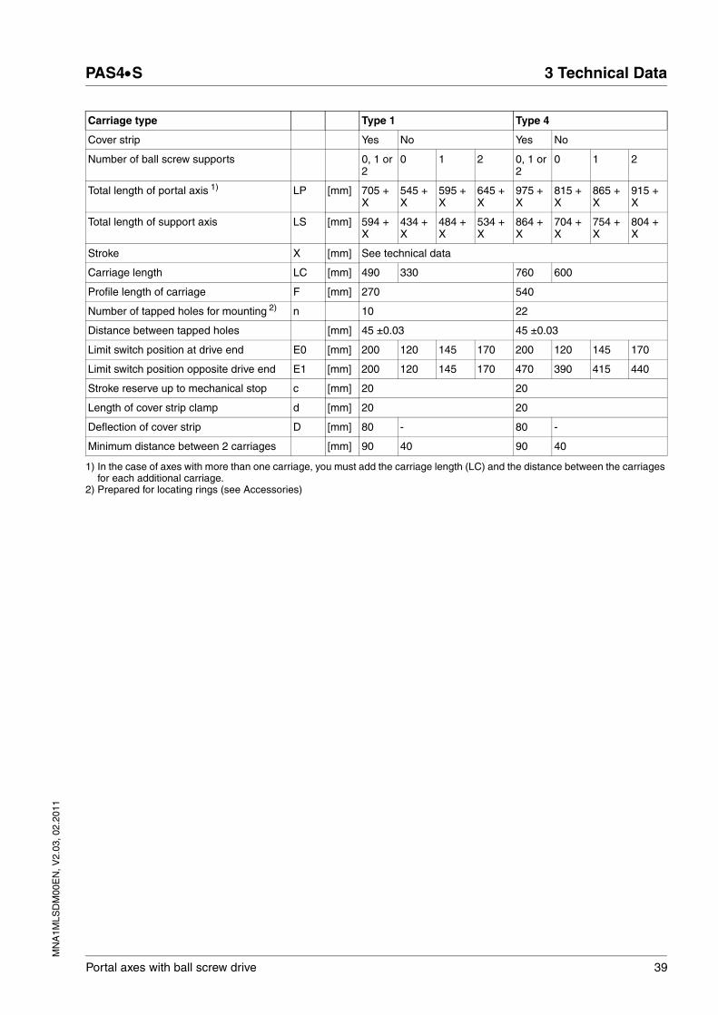
Portal axes with ball screw drive 39
Carriage type Type 1 Type 4
Cover strip Yes No Yes No
Number of ball screw supports 0, 1 or 2
0 1 2 0, 1 or 2
0 1 2
Total length of portal axis 1) LP [mm] 705 + X
545 + X
595 + X
645 + X
975 + X
815 + X
865 + X
915 + X
Total length of support axis LS [mm] 594 + X
434 + X
484 + X
534 + X
864 + X
704 + X
754 + X
804 + X
Stroke X [mm] See technical data
Carriage length LC [mm] 490 330 760 600
Profile length of carriage F [mm] 270 540
Number of tapped holes for mounting 2) n 10 22
Distance between tapped holes [mm] 45 ±0.03 45 ±0.03
Limit switch position at drive end E0 [mm] 200 120 145 170 200 120 145 170
Limit switch position opposite drive end E1 [mm] 200 120 145 170 470 390 415 440
Stroke reserve up to mechanical stop c [mm] 20 20
Length of cover strip clamp d [mm] 20 20
Deflection of cover strip D [mm] 80 - 80 -
Minimum distance between 2 carriages [mm] 90 40 90 40
1) In the case of axes with more than one carriage, you must add the carriage length (LC) and the distance between the carriages for each additional carriage.
2) Prepared for locating rings (see Accessories)

40 Portal axes with ball screw drive
3 Technical Data PAS4•S
MN
A1M
LSD
M00
EN
, V2.
03, 0
2.20
11
3.5 Service life
The service life of the product is a function of the mean forces and tor-ques that act in the system. If multiple forces and torques act simultane-ously, use the following formula to calculate the load k.
Figure 3.10 Forces and torques
The service life of the axis (in km) can be approximated using the load factor and the service life - load characteristic curve.
The application-specific load values appear in the numerator.
The numerator contains the maximum permissible forces and torques. These forces and torques decrease at increasing velocities, see char-acteristic curves in chapter 3.
3.6 Positioning accuracy and repeatability
Positioning accuracy and repeatability depend on temperature, load and velocity changes as well as the accuracy of the ball screw drive and the accuracy of the switching points of the sensors.
3.7 Motor
See the motor manual for details on the motor.
Fy
Fymax+
Fz
Fzmax+
Mx
Mxmax+
My
Mymax+
Mz
Mzmax= k
Fz
Mz
FyMy
Fx
Mx
MN
A1M
LSD
M00
EN
, V2.
03, 0
2.20
11
PAS4•S 4 Installation
Portal axes with ball screw drive 41
44 Installation
@ WARNINGGREAT MASS OR FALLING PARTS
• Consider the mass of the parts when mounting them. It may be necessary to use a crane.
• Mount the parts in such a way (tightening torque, securing screws) that they cannot come loose even in the case of fast acceleration or continuous vibration.
• Take into consideration that axes installed in vertical or tilted posi-tions may move unexpectedly.
Failure to follow these instructions can result in death, serious injury or equipment damage.
@ WARNINGMOTOR WITHOUT BRAKING EFFECT
If power outage, functions or errors cause the power stage to be switched off, the motor is no longer decelerated in a controlled way and may cause damage.
• Verify the mechanical situation.
• If necessary, use a cushioned mechanical stop or a suitable hold-ing brake.
Failure to follow these instructions can result in death, serious injury or equipment damage.
@ WARNINGHOT SURFACES
The heat sink at the product may heat up to over 100°C (212°F) during operation.
• Avoid contact with the hot heat sink.
• Do not allow flammable or heat-sensitive parts in the immediate vicinity.
• Consider the measures for heat dissipation described.
Failure to follow these instructions can result in death or serious injury.

42 Portal axes with ball screw drive
4 Installation PAS4•S
MN
A1M
LSD
M00
EN
, V2.
03, 0
2.20
11
4.1 Preparing installation
The linear axis is a precision product and must be handled with care. Shocks and impacts may damage the guides and the ball screw drive. They may lead to reduced running accuracy and reduced service life.
Transport the product in its packaging as close as possible to the instal-lation site. Do not remove the packaging until the product is at the instal-lation site.
The linear axis may only be lifted at points A and B (see figure). The dis-tance between the end block and point A and between the end block and point B should be one fourth of the total length of the linear axis. If an axis with a mounted motor is lifted, points A and B are to be moved to balance the load. The motor must not be used to lift the load. Support the motor when lifting the axis.
A
B

MN
A1M
LSD
M00
EN
, V2.
03, 0
2.20
11
PAS4•S 4 Installation
Portal axes with ball screw drive 43
4.2 Mechanical installation
Accessibility for servicing When mounting the linear axis, the motor and the sensors, keep in mind that they may have to be accessed for servicing.
Mounting position The linear axis can be installed in any position. However, all external forces and torques must be within the ranges of permissible values. Note that the weight of the linear axis may act as a load, depending on the mounting position.
If a linear axis with a mounted motor is mounted in a vertical or tilted po-sition, the motor should be at the top. This way, the ball screw is under tension and there is no buckling stress.
4.2.1 Standard tightening torques
Special tightening torques are applicable for mounting sensors and elastomer couplings; these tightening torques are listed in the appropri-ate chapters.
The following, generally applicable tightening torques apply to mounting the payload and fastening slot nuts, clamping claws, motor and contact plate with hex socket screws.
Table 4.1 Standard tightening torques for screws, ISO 4762 - 8.8
Thread Wrench size in mm Maximum tightening torque in Nm (lb⋅in)
M3 2.5 1.1 (9.74)
M4 3 2.5 (22.13)
M5 4 5 (44.25)
M6 5 8.5 (75.23)
M8 6 21 (185.87)
M10 8 42 (371.73)
M12 10 70 (619.55)
44 Portal axes with ball screw drive
4 Installation PAS4•S
MN
A1M
LSD
M00
EN
, V2.
03, 0
2.20
11
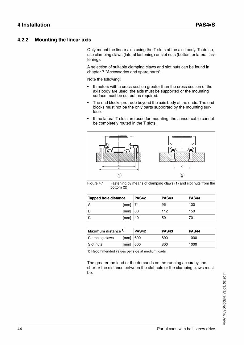
4.2.2 Mounting the linear axis
Only mount the linear axis using the T slots at the axis body. To do so, use clamping claws (lateral fastening) or slot nuts (bottom or lateral fas-tening).
A selection of suitable clamping claws and slot nuts can be found in chapter 7 "Accessories and spare parts".
Note the following:
• If motors with a cross section greater than the cross section of the axis body are used, the axis must be supported or the mounting surface must be cut out as required.
• The end blocks protrude beyond the axis body at the ends. The end blocks must not be the only parts supported by the mounting sur-face.
• If the lateral T slots are used for mounting, the sensor cable cannot be completely routed in the T slots.
Figure 4.1 Fastening by means of clamping claws (1) and slot nuts from thebottom (2)
The greater the load or the demands on the running accuracy, the shorter the distance between the slot nuts or the clamping claws must be.
CA
B
1 2
Tapped hole distance PAS42 PAS43 PAS44
A [mm] 74 96 130
B [mm] 88 112 150
C [mm] 40 50 70
Maximum distance 1)
1) Recommended values per side at medium loads
PAS42 PAS43 PAS44
Clamping claws [mm] 600 800 1000
Slot nuts [mm] 600 800 1000

MN
A1M
LSD
M00
EN
, V2.
03, 0
2.20
11
PAS4•S 4 Installation
Portal axes with ball screw drive 45
Alignment for running accuracy Due to the manufacturing process of the extruded profiles, a linear axis has a certain tolerance in terms in straightness and twist. The deviations are generally well within the specifications of EN 12020-2 in the case of the product.
Perform the following lateral alignment procedure for running accuracy.
� The mounting surface must be machined smooth and flat.
� Start by tightening the fastening screws of the slot nut or clamping claws with a low tightening torque.
� Provide a reference plane alongside the linear axis.
� Place a dial gauge onto the carriage.
� Move the carriage and record the deviation with reference to the ref-erence plane over the entire stroke.
� Correct the deviations by lateral alignment of the linear axis and by tightening the screws appropriately. Observe the standard tighten-ing torques 43.
4.2.3 Mounting the contact plate
A contact plate must be mounted to the carriage for the inductive sen-sors. Fastening threads are located at both sides of the carriage.
Unless otherwise specified, the standard tightening torques indicated on page 43 apply.
Before mounting See chapter 7 "Accessories and spare parts", subchapter 7.5 "Sensors and additional parts" for suitable contact plates.
You need a set of hex keys.
� Clean all parts you will use.
� Check all parts for damage.
Procedure
� For mounting, select the side of the carriage that will be easily accessible for service.
� Screw the contact plate to the carriage with M4 screws.
� Align the contact plate in parallel with the carriage so as to have the same switching distance on both sides.
46 Portal axes with ball screw drive
4 Installation PAS4•S
MN
A1M
LSD
M00
EN
, V2.
03, 0
2.20
11
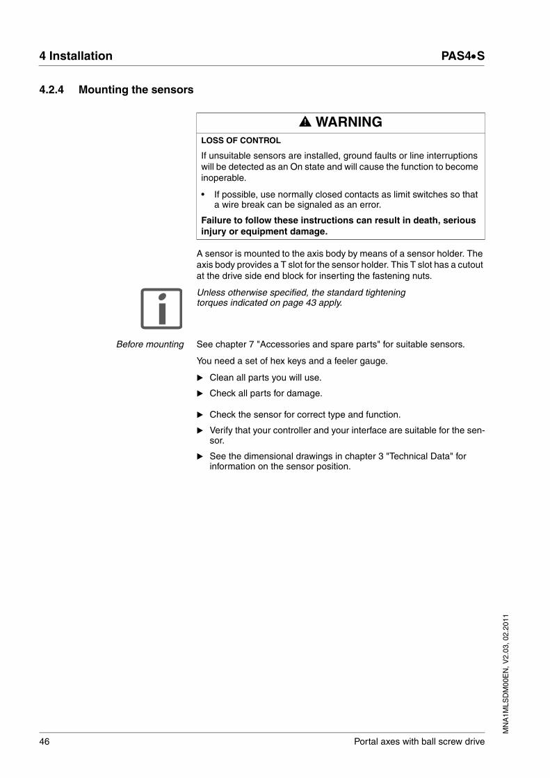
4.2.4 Mounting the sensors
A sensor is mounted to the axis body by means of a sensor holder. The axis body provides a T slot for the sensor holder. This T slot has a cutout at the drive side end block for inserting the fastening nuts.
Unless otherwise specified, the standard tightening torques indicated on page 43 apply.
Before mounting See chapter 7 "Accessories and spare parts" for suitable sensors.
You need a set of hex keys and a feeler gauge.
� Clean all parts you will use.
� Check all parts for damage.
� Check the sensor for correct type and function.
� Verify that your controller and your interface are suitable for the sen-sor.
� See the dimensional drawings in chapter 3 "Technical Data" for information on the sensor position.
@ WARNINGLOSS OF CONTROL
If unsuitable sensors are installed, ground faults or line interruptions will be detected as an On state and will cause the function to become inoperable.
• If possible, use normally closed contacts as limit switches so that a wire break can be signaled as an error.
Failure to follow these instructions can result in death, serious injury or equipment damage.
MN
A1M
LSD
M00
EN
, V2.
03, 0
2.20
11
PAS4•S 4 Installation
Portal axes with ball screw drive 47
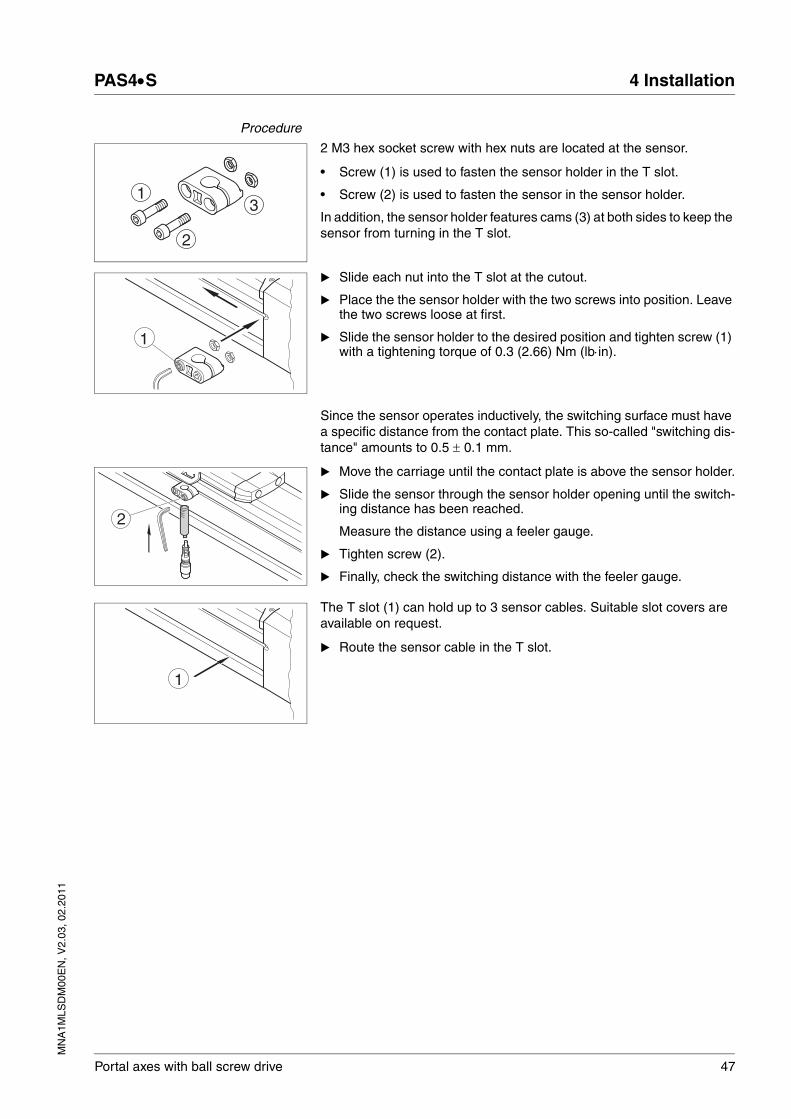
Procedure
2 M3 hex socket screw with hex nuts are located at the sensor.
• Screw (1) is used to fasten the sensor holder in the T slot.
• Screw (2) is used to fasten the sensor in the sensor holder.
In addition, the sensor holder features cams (3) at both sides to keep the sensor from turning in the T slot.
� Slide each nut into the T slot at the cutout.
� Place the the sensor holder with the two screws into position. Leave the two screws loose at first.
� Slide the sensor holder to the desired position and tighten screw (1) with a tightening torque of 0.3 (2.66) Nm (lb⋅in).
Since the sensor operates inductively, the switching surface must have a specific distance from the contact plate. This so-called "switching dis-tance" amounts to 0.5 ± 0.1 mm.
� Move the carriage until the contact plate is above the sensor holder.
� Slide the sensor through the sensor holder opening until the switch-ing distance has been reached.
Measure the distance using a feeler gauge.
� Tighten screw (2).
� Finally, check the switching distance with the feeler gauge.
The T slot (1) can hold up to 3 sensor cables. Suitable slot covers are available on request.
� Route the sensor cable in the T slot.
1
2
3
1
2
1

48 Portal axes with ball screw drive
4 Installation PAS4•S
MN
A1M
LSD
M00
EN
, V2.
03, 0
2.20
11
4.2.5 Mounting the motor and the gearbox
The motor or the gearbox can be mounted in different arrangements (turned in increments of 4 x 90°).
Unless otherwise specified, the standard tightening torques indicated on page 43 apply.
Special tightening torques
Table 4.2 Tightening torques and mounting dimensions clamping hub
Before mounting See chapter 7 "Accessories and spare parts" for suitable elastomer cou-plings (elastomer spiders, clamping hubs).
You need a set of hex keys and a torque wrench with hexagon socket.
� Clean all parts you will use.
� Check all parts for damage.
NOTE: Polluted or damaged parts may cause run-out which has an ad-verse effect on the service life of the elastomer coupling and the linear axis.
Mounting the elastomer coupling The elastomer coupling has 2 clamping hubs with different holes.
� Slide the matching clamping hub onto the shaft extension of the lin-ear axis all the way to the stop.
� Tighten the clamping screw at the clamping hub with the tightening torque specified in Table 4.2.
� Fit the elastomer spider onto the clamping hub.
Slightly greasing the elastomer spider or the hub facilitates the fit-ting process. Use only mineral oil based lubricants without additives or silicon based lubricants.
NOTE: If the elastomer spider can be fitted too easily (without preloading), it must be replaced.
� Mount the coupling housing with the 4 screws. Verify that the cou-pling housing has even contact.
Clamping hub PAS42 PAS43 PAS44
Screw ISO 4762 - 10.9 M6 x 16 M6 x 20 M8 x 25
Wrench size [mm] 5 5 6
Tightening torque [Nm](lb⋅in)
14(123.91)
14(123.91)
35(309.78)
Mounting dimension [mm] 13 14 14
MN
A1M
LSD
M00
EN
, V2.
03, 0
2.20
11
PAS4•S 4 Installation
Portal axes with ball screw drive 49
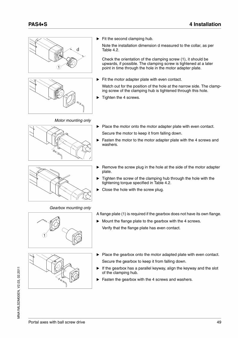
� Fit the second clamping hub.
Note the installation dimension d measured to the collar, as per Table 4.2.
Check the orientation of the clamping screw (1), it should be upwards, if possible. The clamping screw is tightened at a later point in time through the hole in the motor adapter plate.
� Fit the motor adapter plate with even contact.
Watch out for the position of the hole at the narrow side. The clamp-ing screw of the clamping hub is tightened through this hole.
� Tighten the 4 screws.
Motor mounting only
� Place the motor onto the motor adapter plate with even contact.
Secure the motor to keep it from falling down.
� Fasten the motor to the motor adapter plate with the 4 screws and washers.
� Remove the screw plug in the hole at the side of the motor adapter plate.
� Tighten the screw of the clamping hub through the hole with the tightening torque specified in Table 4.2.
� Close the hole with the screw plug.
Gearbox mounting only
A flange plate (1) is required if the gearbox does not have its own flange.
� Mount the flange plate to the gearbox with the 4 screws.
Verify that the flange plate has even contact.
� Place the gearbox onto the motor adapted plate with even contact.
Secure the gearbox to keep it from falling down.
� If the gearbox has a parallel keyway, align the keyway and the slot of the clamping hub.
� Fasten the gearbox with the 4 screws and washers.
d
1
1

50 Portal axes with ball screw drive
4 Installation PAS4•S
MN
A1M
LSD
M00
EN
, V2.
03, 0
2.20
11
� Remove the screw plug in the hole at the side of the motor adapter plate.
� Tighten the screw of the clamping hub through the hole with the tightening torque specified in Table 4.2.
� Close the hole with the screw plug.
Please refer to the gearbox manual for mounting a motor to the gearbox.
MN
A1M
LSD
M00
EN
, V2.
03, 0
2.20
11
PAS4•S 4 Installation
Portal axes with ball screw drive 51
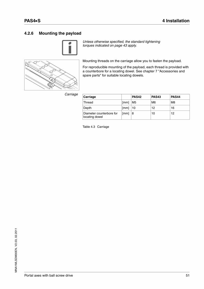
4.2.6 Mounting the payload
Unless otherwise specified, the standard tightening torques indicated on page 43 apply.
Mounting threads on the carriage allow you to fasten the payload.
For reproducible mounting of the payload, each thread is provided with a counterbore for a locating dowel. See chapter 7 "Accessories and spare parts" for suitable locating dowels.
Carriage
Table 4.3 Carriage
Carriage PAS42 PAS43 PAS44
Thread [mm] M5 M6 M8
Depth [mm] 10 12 16
Diameter counterbore for locating dowel
[mm] 8 10 12
52 Portal axes with ball screw drive
4 Installation PAS4•S
MN
A1M
LSD
M00
EN
, V2.
03, 0
2.20
11
4.3 Electrical installation
4.3.1 Connecting the sensors
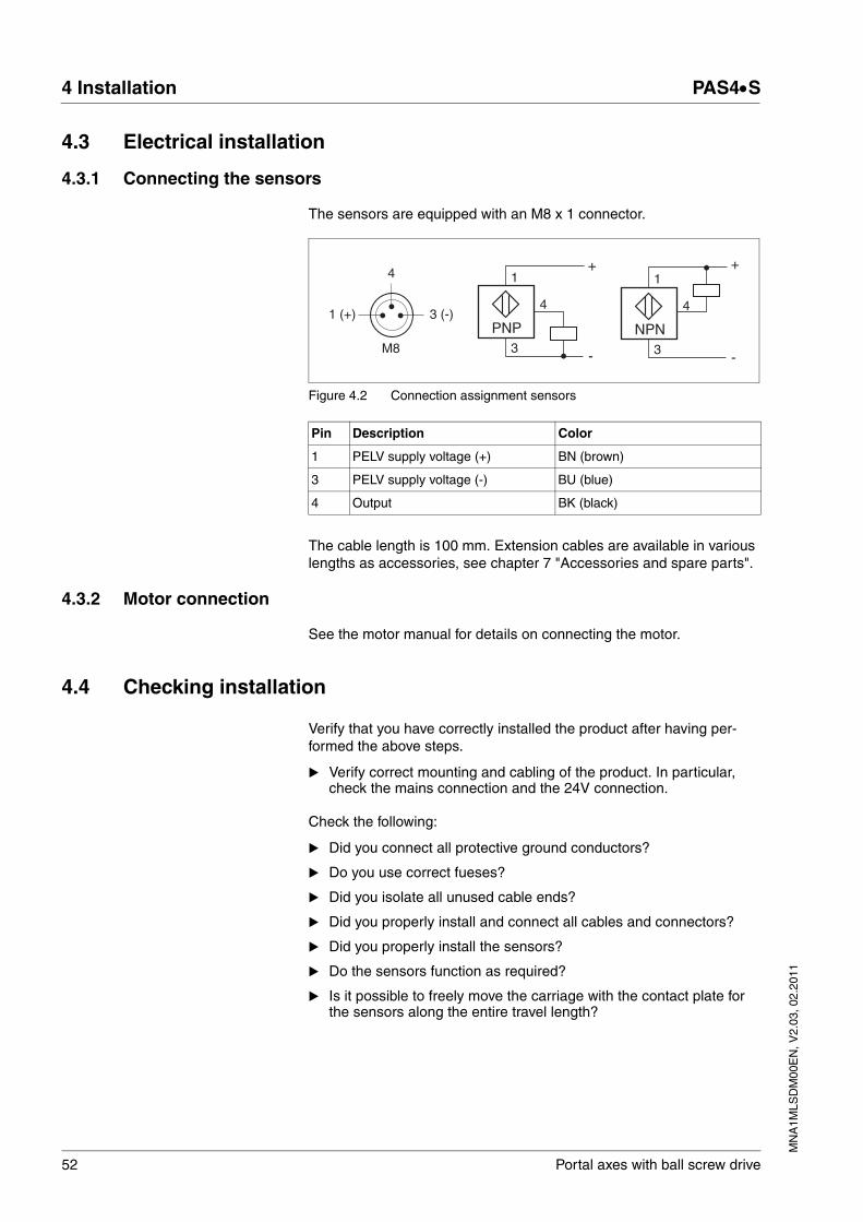
The sensors are equipped with an M8 x 1 connector.
Figure 4.2 Connection assignment sensors
The cable length is 100 mm. Extension cables are available in various lengths as accessories, see chapter 7 "Accessories and spare parts".
4.3.2 Motor connection
See the motor manual for details on connecting the motor.
4.4 Checking installation
Verify that you have correctly installed the product after having per-formed the above steps.
� Verify correct mounting and cabling of the product. In particular, check the mains connection and the 24V connection.
Check the following:
� Did you connect all protective ground conductors?
� Do you use correct fueses?
� Did you isolate all unused cable ends?
� Did you properly install and connect all cables and connectors?
� Did you properly install the sensors?
� Do the sensors function as required?
� Is it possible to freely move the carriage with the contact plate for the sensors along the entire travel length?
Pin Description Color
1 PELV supply voltage (+) BN (brown)
3 PELV supply voltage (-) BU (blue)
4 Output BK (black)
3
1
4
PNP
+
-
1 (+) 3 (-)
4
M8 3
1
4
NPN
+
-
MN
A1M
LSD
M00
EN
, V2.
03, 0
2.20
11
PAS4•S 5 Commissioning
Portal axes with ball screw drive 53
55 Commissioning
@ WARNINGUNEXPECTED MOVEMENT
When the axis is operated for the first time, there is a risk of unex-pected movements caused by possible wiring errors or unsuitable pa-rameters.
• Verify that that the axis is properly fastened so it cannot come loose even in the case of fast acceleration.
• The carriage of linear axes in vertical or tilted positions may move unexpectedly.
• Verify that a functioning button for emergency stop is within reach.
• Verify that the system is free and ready for the movement before switching it on.
• Run initial tests at reduced velocity.
Failure to follow these instructions can result in death, serious injury or equipment damage.
54 Portal axes with ball screw drive
5 Commissioning PAS4•S
MN
A1M
LSD
M00
EN
, V2.
03, 0
2.20
11
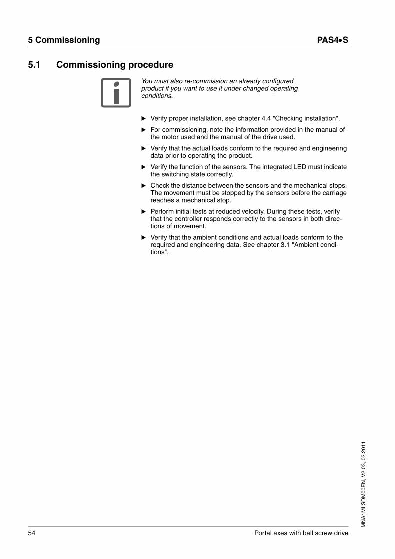
5.1 Commissioning procedure
You must also re-commission an already configured product if you want to use it under changed operating conditions.
� Verify proper installation, see chapter 4.4 "Checking installation".
� For commissioning, note the information provided in the manual of the motor used and the manual of the drive used.
� Verify that the actual loads conform to the required and engineering data prior to operating the product.
� Verify the function of the sensors. The integrated LED must indicate the switching state correctly.
� Check the distance between the sensors and the mechanical stops. The movement must be stopped by the sensors before the carriage reaches a mechanical stop.
� Perform initial tests at reduced velocity. During these tests, verify that the controller responds correctly to the sensors in both direc-tions of movement.
� Verify that the ambient conditions and actual loads conform to the required and engineering data. See chapter 3.1 "Ambient condi-tions".
MN
A1M
LSD
M00
EN
, V2.
03, 0
2.20
11
PAS4•S 6 Diagnostics and troubleshooting
Portal axes with ball screw drive 55
66 Diagnostics and troubleshooting
6.1 Troubleshooting
Error Cause Troubleshooting
Sensor overtraveled Sensor Adjust or replace sensors, see page 72
Controller Check controller
Motor load increases, controller switches off because of overload.
Guides and/or ball screw drive under mechanical tension or excessive friction caused by poor lubrication.
Contact service
Noise and vibrations at high speed of rotation of the ball screw shaft.
Speed of rotation too high Reduce speed of rotation
Poor lubrication (in the case of noise) Lubricate, see page 80
Run-out of the ball screw shaft caused by impact or shock
The ball screw must be replaced. Contact service
Running inaccuracy and noise of the guides
Poor lubrication Lubricate, see page 80
Damage to the guides, for example by shock or impact on the carriage
Replace guides, contact service
Carriage has backlash and posi-tions inaccurately
Backlash in ball screw drive or guides after a collision or poor lubrication
Contact service

56 Portal axes with ball screw drive
6 Diagnostics and troubleshooting PAS4•S
MN
A1M
LSD
M00
EN
, V2.
03, 0
2.20
11
MN
A1M
LSD
M00
EN
, V2.
03, 0
2.20
11
PAS4•S 7 Accessories and spare parts
Portal axes with ball screw drive 57
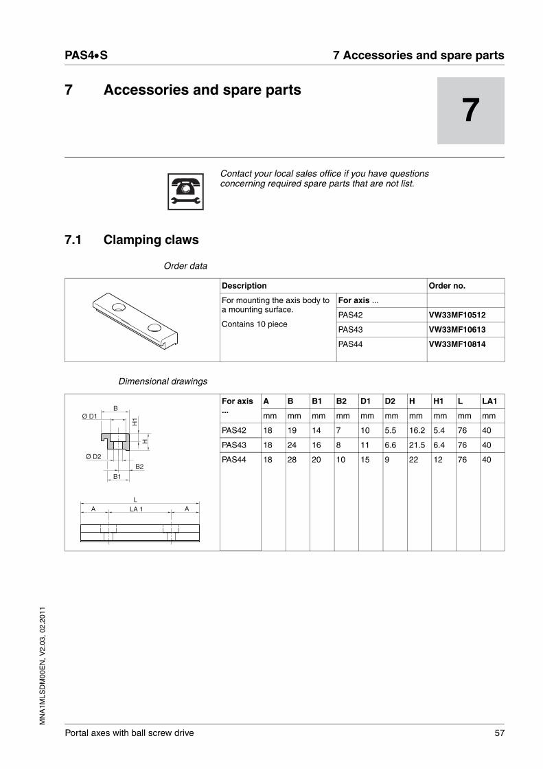
77 Accessories and spare parts
Contact your local sales office if you have questions concerning required spare parts that are not list.
7.1 Clamping claws
Order data
Dimensional drawings
Description Order no.
For mounting the axis body to a mounting surface.
Contains 10 piece
For axis ...
PAS42 VW33MF10512
PAS43 VW33MF10613
PAS44 VW33MF10814
For axis ...
A B B1 B2 D1 D2 H H1 L LA1
mm mm mm mm mm mm mm mm mm mm
PAS42 18 19 14 7 10 5.5 16.2 5.4 76 40
PAS43 18 24 16 8 11 6.6 21.5 6.4 76 40
PAS44 18 28 20 10 15 9 22 12 76 40
Ø D1
B1
B2
Ø D2
H1
H
LA LA 1 A
B

58 Portal axes with ball screw drive
7 Accessories and spare parts PAS4•S
MN
A1M
LSD
M00
EN
, V2.
03, 0
2.20
11
7.2 Slot nuts
Order data
Dimensional drawings
7.3 Locating dowels
Order data
Dimensional drawings
Description Order no.
The slot nuts are inserted into the T slots of the axis body to fas-ten the axis or parts of the axis.
Contains 10 piece
For axis ... Slot nut type
PAS42 5 steel M5 VW33MF010T5N5
PAS43 6 steel M6 VW33MF010T6N6
PAS44 8 steel M6 VW33MF010T8N6
8 steel M8 VW33MF010T8N8
Slot nut type B D H L LA
For axis ... mm mm mm mm mm
PAS42 5 steel M5 8 5 4 11.5 4
PAS43 6 steel M6 10.6 6 6.4 17 5.5
PAS44 8 steel M6 13.8 6 7.3 23 6.5
8 steel M8 13.8 8 7.3 23 7.5
LA
B
H D
L
Description Order no.
For precise and reproducible mounting of the payload, the locating dowels are inserted into the holes at the carriage.
Contains 20 piece
For axis ...
PAS42 VW33MF020LD01
PAS43 VW33MF020LD02
PAS44 VW33MF020LD03
D1 D2
For axis ... mm mm
PAS42 5.5 8 h6
PAS43 6.6 10 h6
PAS44 9 12 h6
Ø D1
Ø D2
3,8

MN
A1M
LSD
M00
EN
, V2.
03, 0
2.20
11
PAS4•S 7 Accessories and spare parts
Portal axes with ball screw drive 59
7.4 T slot covers
Order data
Description Order no.
Length 2 m
Contains 5 piece
For axis ... T slot size
PAS42 5 VW33MC05B05
PAS43 6 VW33MC05A06
PAS44 8 VW33MC05A08
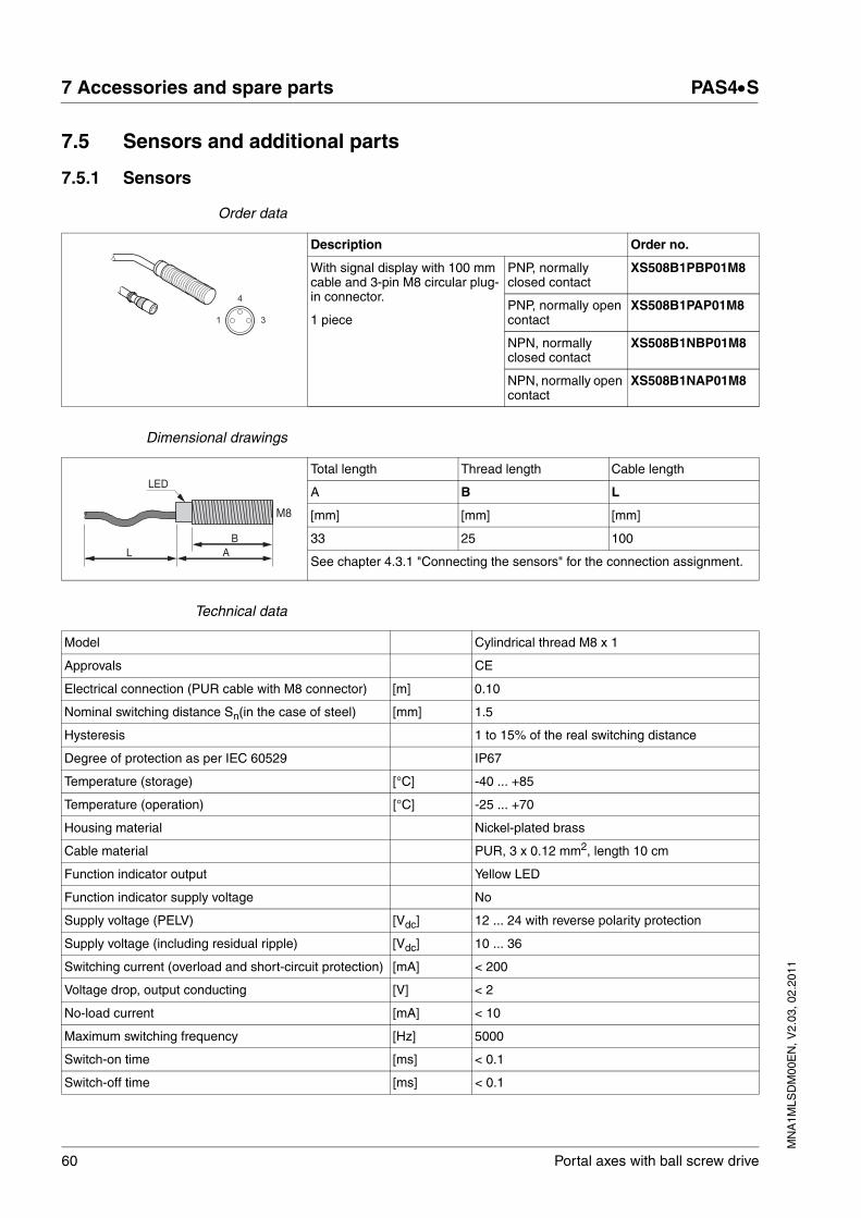
60 Portal axes with ball screw drive
7 Accessories and spare parts PAS4•S
MN
A1M
LSD
M00
EN
, V2.
03, 0
2.20
11
7.5 Sensors and additional parts
7.5.1 Sensors
Order data
Dimensional drawings
Technical data
Description Order no.
With signal display with 100 mm cable and 3-pin M8 circular plug-in connector.
1 piece
PNP, normally closed contact
XS508B1PBP01M8
PNP, normally open contact
XS508B1PAP01M8
NPN, normally closed contact
XS508B1NBP01M8
NPN, normally open contact
XS508B1NAP01M8
1
4
3
Total length Thread length Cable length
A B L
[mm] [mm] [mm]
33 25 100
See chapter 4.3.1 "Connecting the sensors" for the connection assignment.
LED
AB
M8
L
Model Cylindrical thread M8 x 1
Approvals CE
Electrical connection (PUR cable with M8 connector) [m] 0.10
Nominal switching distance Sn(in the case of steel) [mm] 1.5
Hysteresis 1 to 15% of the real switching distance
Degree of protection as per IEC 60529 IP67
Temperature (storage) [°C] -40 ... +85
Temperature (operation) [°C] -25 ... +70
Housing material Nickel-plated brass
Cable material PUR, 3 x 0.12 mm2, length 10 cm
Function indicator output Yellow LED
Function indicator supply voltage No
Supply voltage (PELV) [Vdc] 12 ... 24 with reverse polarity protection
Supply voltage (including residual ripple) [Vdc] 10 ... 36
Switching current (overload and short-circuit protection) [mA] < 200
Voltage drop, output conducting [V] < 2
No-load current [mA] < 10
Maximum switching frequency [Hz] 5000
Switch-on time [ms] < 0.1
Switch-off time [ms] < 0.1

MN
A1M
LSD
M00
EN
, V2.
03, 0
2.20
11
PAS4•S 7 Accessories and spare parts
Portal axes with ball screw drive 61
7.5.2 Sensor extension cable
Order data
7.5.3 Sensor holder
Order data
7.5.4 Contact plate
Order data
Description Order no.
Suitable for drag chain applications; sensor side end 3-pin M8 circular connector, sec-ond cable end open
Contains 1 piece
5 m VW32SBCBGA050
10 m VW32SBCBGA100
20 m VW32SBCBGA200
1
4
3
Description Order no.
For standard limit switch with 8 mm diameter; movable
Contains 10 piece
VW33MF010M8
Description Order no.
For mounting to the carriage of the axis
Content1 contact plate2 screws
VW33MASP1
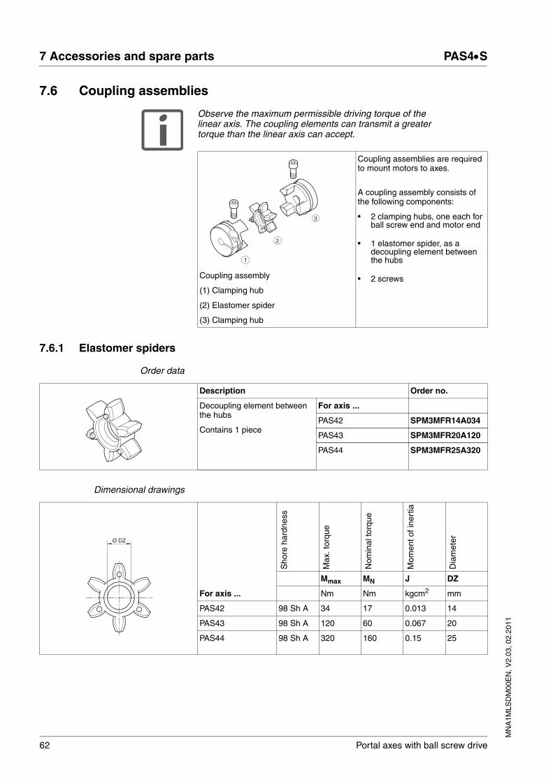
62 Portal axes with ball screw drive
7 Accessories and spare parts PAS4•S
MN
A1M
LSD
M00
EN
, V2.
03, 0
2.20
11
7.6 Coupling assemblies
Observe the maximum permissible driving torque of the linear axis. The coupling elements can transmit a greater torque than the linear axis can accept.
7.6.1 Elastomer spiders
Order data
Dimensional drawings
Coupling assemblies are required to mount motors to axes.
A coupling assembly consists of the following components:
• 2 clamping hubs, one each for ball screw end and motor end
• 1 elastomer spider, as a decoupling element between the hubs
• 2 screwsCoupling assembly
(1) Clamping hub
(2) Elastomer spider
(3) Clamping hub
1
2
3
Description Order no.
Decoupling element between the hubs
Contains 1 piece
For axis ...
PAS42 SPM3MFR14A034
PAS43 SPM3MFR20A120
PAS44 SPM3MFR25A320
Sho
re h
ardn
ess
Max
. tor
que
Nom
inal
torq
ue
Mom
ent o
f ine
rtia
Dia
met
er
Mmax MN J DZ
For axis ... Nm Nm kgcm2 mm
PAS42 98 Sh A 34 17 0.013 14
PAS43 98 Sh A 120 60 0.067 20
PAS44 98 Sh A 320 160 0.15 25
Ø DZ
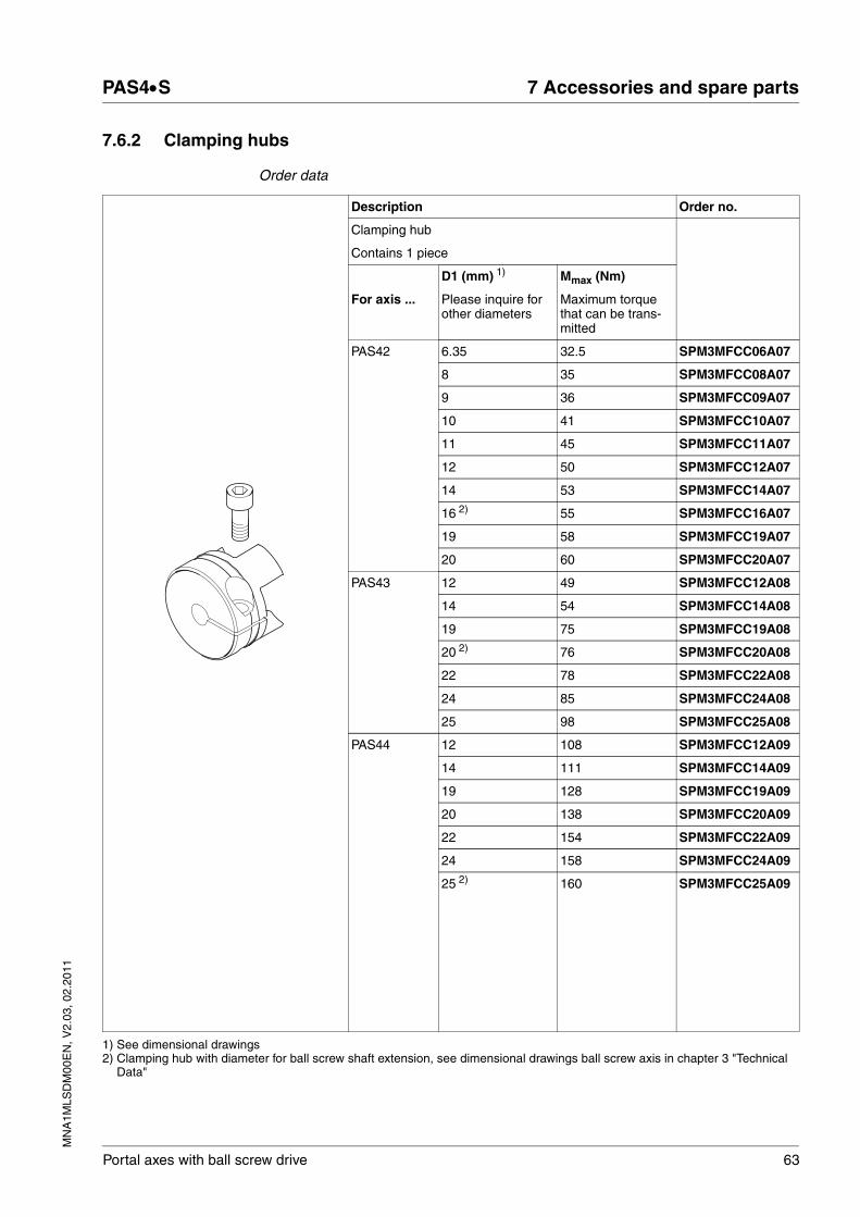
MN
A1M
LSD
M00
EN
, V2.
03, 0
2.20
11
PAS4•S 7 Accessories and spare parts
Portal axes with ball screw drive 63
7.6.2 Clamping hubs
Order data
Description Order no.
Clamping hub
Contains 1 piece
D1 (mm) 1) Mmax (Nm)
For axis ... Please inquire for other diameters
Maximum torque that can be trans-mitted
PAS42 6.35 32.5 SPM3MFCC06A07
8 35 SPM3MFCC08A07
9 36 SPM3MFCC09A07
10 41 SPM3MFCC10A07
11 45 SPM3MFCC11A07
12 50 SPM3MFCC12A07
14 53 SPM3MFCC14A07
16 2) 55 SPM3MFCC16A07
19 58 SPM3MFCC19A07
20 60 SPM3MFCC20A07
PAS43 12 49 SPM3MFCC12A08
14 54 SPM3MFCC14A08
19 75 SPM3MFCC19A08
20 2) 76 SPM3MFCC20A08
22 78 SPM3MFCC22A08
24 85 SPM3MFCC24A08
25 98 SPM3MFCC25A08
PAS44 12 108 SPM3MFCC12A09
14 111 SPM3MFCC14A09
19 128 SPM3MFCC19A09
20 138 SPM3MFCC20A09
22 154 SPM3MFCC22A09
24 158 SPM3MFCC24A09
25 2) 160 SPM3MFCC25A09
1) See dimensional drawings2) Clamping hub with diameter for ball screw shaft extension, see dimensional drawings ball screw axis in chapter 3 "Technical
Data"

64 Portal axes with ball screw drive
7 Accessories and spare parts PAS4•S
MN
A1M
LSD
M00
EN
, V2.
03, 0
2.20
11
Dimensional drawings
Mom
ent o
f ine
rtia
Scr
ew IS
O 4
762
Wre
nch
size
Tig
hten
ing
torq
ue
Hub
leng
th
Bor
e de
pth
H7
Dis
tanc
e be
twee
n ce
nter
s
Insi
de d
iam
eter
Out
side
dia
met
er
For axis ...
J E A B C D1 D2 DK F
kgcm2 mm Nm(lb⋅in)
mm
PAS42 0.15 M6 5 14(123.91)
31 17 8 1) 40 45 14
PAS43 0.55 M6 5 14(123.91)
36 20 10 1) 55 57.5
20
PAS44 1.22 M8 6 35(309.78)
39 21 9 1) 65 73 25
1) See order data
E (ISO 4762)
A - A
A
A
C
A
Ø D
2
B
F
Ø DK
Ø D1
MN
A1M
LSD
M00
EN
, V2.
03, 0
2.20
11
PAS4•S 7 Accessories and spare parts
Portal axes with ball screw drive 65
7.7 Grease guns
Order data
7.8 Cover strips
Order data
Designation Description Order no.
Single-hand high-pressure grease gun With nozzle for the lubrication of the linear axes with recirculating ball bearing guide. Suitable nozzle type D.Volume: 120 cm3; delivery volume: 0.5 cm3/stroke
VW33MAP01
Single-hand high-pressure oil gun With nozzle for the lubrication of the linear axes with roller guide. Suitable nozzle type D.Volume: 120 cm3; delivery volume: 0.5 cm3/stroke
VW33MAP02
Nozzle type D6 90° For grease nipple type D6; nipple 90°, Ø 6 mm; length 20 mm; with M4 pointed nozzle 90° lateral
VW33MAT01
Nozzle type D6 20° For grease nipple type D6; nipple 20°, Ø 6 mm; length 20 mm; with M4 pointed nozzle 20° angled
VW33MAT02
Description Order no.
For axis ... Width (mm) Height (mm) Length (m)
PAS42 36 0.15 3 SPM3MAC36L030
6 SPM3MAC36L060
PAS43 45 0.15 3 SPM3MAC45L030
6 SPM3MAC45L060
PAS44 65 0.15 3 SPM3MAC65L030
6 SPM3MAC65L060
66 Portal axes with ball screw drive
7 Accessories and spare parts PAS4•S
MN
A1M
LSD
M00
EN
, V2.
03, 0
2.20
11
7.9 Strip deflection
Order data
7.10 Cover strip clamp
Order data
7.11 Magnetic strips
Order data
Description Order no.
Kit with1 strip deflection1 deflection unit with brush1 holding plate1 rubber buffers4 screws
For axis ...
PAS42 SPM3MAC2D0042
PAS43 SPM3MAC3D0043
PAS44 SPM3MAC4D0044
Description Order no.
Kit with1 belt deflection1 clamping plate2 screws 2 set screws2 nuts
For axis ...
PAS42 SPM3MAC1F042
PAS43 SPM3MAC1F043
PAS44 SPM3MAC1F044
Description Order no.
Contains 2 piece
For axis ... Width (mm) Height (mm) Length (m)
PAS42 4.0 1 1.5 SPM3MAW1S415
3 SPM3MAW1S430
6 SPM3MAW1S460
PAS43 / PAS44 6.0 1 1.5 SPM3MAW1S615
3 SPM3MAW1S630
6 SPM3MAW1S660
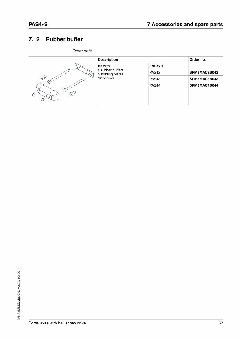
MN
A1M
LSD
M00
EN
, V2.
03, 0
2.20
11
PAS4•S 7 Accessories and spare parts
Portal axes with ball screw drive 67
7.12 Rubber buffer
Order data
Description Order no.
Kit with 2 rubber buffers2 holding plates12 screws
For axis ...
PAS42 SPM3MAC2B042
PAS43 SPM3MAC3B043
PAS44 SPM3MAC4B044

68 Portal axes with ball screw drive
7 Accessories and spare parts PAS4•S
MN
A1M
LSD
M00
EN
, V2.
03, 0
2.20
11

MN
A1M
LSD
M00
EN
, V2.
03, 0
2.20
11
PAS4•S 8 Service, maintenance and disposal
Portal axes with ball screw drive 69
88 Service, maintenance and disposal
8.1 Service address
If you cannot resolve an error yourself please contact your sales office. Have the following details available:
• Nameplate (type, identification number, serial number, DOM, ...)
• Type of error (with LED flash code or error number)
• Previous and concomitant circumstances
• Your own assumptions concerning the cause of the error
Also include this information if you return the product for inspection or re-pair.
If you have any questions please contact your sales office. Your sales office staff will be happy to give you the name of a customer service office in your area.
http://www.schneider-electric.com
@ WARNINGGREAT MASS OR FALLING PARTS
• Consider the mass of the parts when mounting them. It may be necessary to use a crane.
• Mount the parts in such a way (tightening torque, securing screws) that they cannot come loose even in the case of fast acceleration or continuous vibration.
• Take into consideration that axes installed in vertical or tilted posi-tions may move unexpectedly.
Failure to follow these instructions can result in death, serious injury or equipment damage.

70 Portal axes with ball screw drive
8 Service, maintenance and disposal PAS4•S
MN
A1M
LSD
M00
EN
, V2.
03, 0
2.20
11
8.2 Checks after collisions
Components of the linear axis may be damaged or destroyed as a result of a collision.
� After a collision, inspect the drive elements, the linear guide and the elastomer coupling for damage according to the instructions in the following chapters.
8.2.1 Ball screw drive
� Check the linear axis for unusual noise and vibrations.
� Perform a visual inspection of the ball screw drive for damage. To do so, remove the cover strip as described in chapter 8.3.4 "Replac-ing the cover strip and the strip deflection".
A damaged ball screw drive must be replaced. Contact your local sales office.
8.2.2 Ball screw bearing
� Check the linear axis for unusual noise and vibrations.
A damaged ball screw bearing must be replaced. Contact your local sales office.
8.2.3 Linear guide
The linear guide consists of the guide carriage and the recirculating ball bearing guide.
� Check the guide carriage for play. If the guide carriage has play, the pre-tension has been changed. The pre-tension of the guide car-riage can only be adjusted by the manufacturer. Note the serial number of the linear axis and contact your local sales office.
� Perform a visual inspection of the linear guide for damage. To do so, remove the cover strip as described in chapter 8.3.4 "Replacing the cover strip and the strip deflection".
� Check for irregular noise or vibration. Irregular noise or vibration indicates a deformation in the linear guide. Deformation will cause rapid wear.
A damaged linear guide must be replaced. Contact your local sales office.

MN
A1M
LSD
M00
EN
, V2.
03, 0
2.20
11
PAS4•S 8 Service, maintenance and disposal
Portal axes with ball screw drive 71
8.2.4 Elastomer coupling
� Perform a visual inspection of the elastomer coupling for damage. To do so, remove the motor or the gearbox as described in chapter 8.3.2 "Replacing the motor or the gearbox".
NOTE: A damaged elastomer coupling must be replaced. See chapter 8.3.3 "Replacing the elastomer coupling" for the procedure.
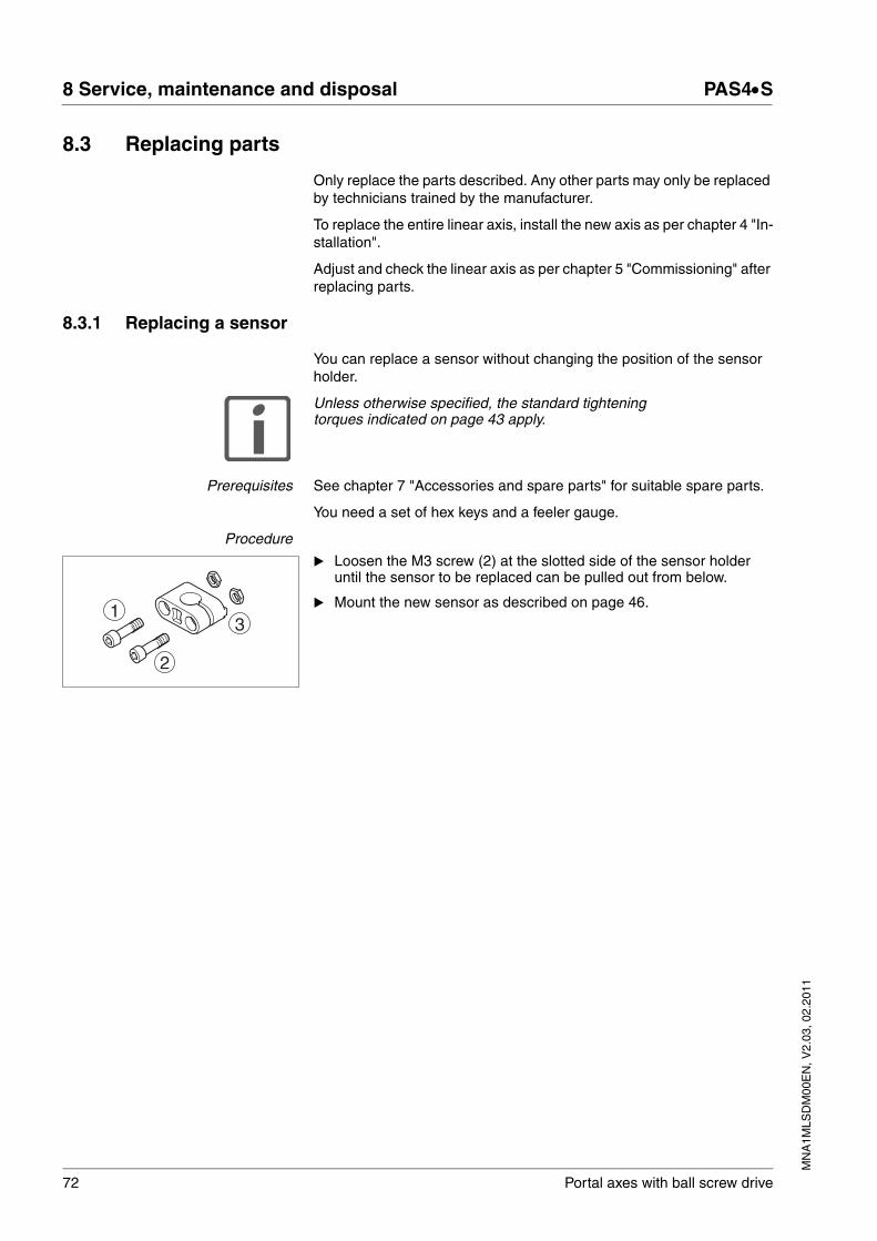
72 Portal axes with ball screw drive
8 Service, maintenance and disposal PAS4•S
MN
A1M
LSD
M00
EN
, V2.
03, 0
2.20
11
8.3 Replacing parts
Only replace the parts described. Any other parts may only be replaced by technicians trained by the manufacturer.
To replace the entire linear axis, install the new axis as per chapter 4 "In-stallation".
Adjust and check the linear axis as per chapter 5 "Commissioning" after replacing parts.
8.3.1 Replacing a sensor
You can replace a sensor without changing the position of the sensor holder.
Unless otherwise specified, the standard tightening torques indicated on page 43 apply.
Prerequisites See chapter 7 "Accessories and spare parts" for suitable spare parts.
You need a set of hex keys and a feeler gauge.
Procedure
� Loosen the M3 screw (2) at the slotted side of the sensor holder until the sensor to be replaced can be pulled out from below.
� Mount the new sensor as described on page 46.1
2
3
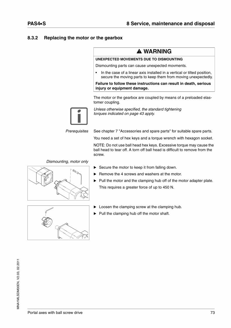
MN
A1M
LSD
M00
EN
, V2.
03, 0
2.20
11
PAS4•S 8 Service, maintenance and disposal
Portal axes with ball screw drive 73
8.3.2 Replacing the motor or the gearbox
The motor or the gearbox are coupled by means of a preloaded elas-tomer coupling.
Unless otherwise specified, the standard tightening torques indicated on page 43 apply.
Prerequisites See chapter 7 "Accessories and spare parts" for suitable spare parts.
You need a set of hex keys and a torque wrench with hexagon socket.
NOTE: Do not use ball head hex keys. Excessive torque may cause the ball head to tear off. A torn off ball head is difficult to remove from the screw.
Dismounting, motor only
� Secure the motor to keep it from falling down.
� Remove the 4 screws and washers at the motor.
� Pull the motor and the clamping hub off of the motor adapter plate.
This requires a greater force of up to 450 N.
� Loosen the clamping screw at the clamping hub.
� Pull the clamping hub off the motor shaft.
@ WARNINGUNEXPECTED MOVEMENTS DUE TO DISMOUNTING
Dismounting parts can cause unexpected movments.
• In the case of a linear axis installed in a vertical or tilted position, secure the moving parts to keep them from moving unexpectedly.
Failure to follow these instructions can result in death, serious injury or equipment damage.

74 Portal axes with ball screw drive
8 Service, maintenance and disposal PAS4•S
MN
A1M
LSD
M00
EN
, V2.
03, 0
2.20
11
Dismounting, gearbox only
See the gearbox manual for details on removing a motor from the gearbox.
� Remove the 4 screws and washers at the gearbox flange.
� Pull the gearbox and the clamping hub off of the motor adapter plate.
This requires a greater force of up to 450 N.
� Loosen the clamping screw at the clamping hub.
� Pull the clamping hub off the gearbox shaft.
If the gearbox does not have its own flange, the flange plate (1) must be dismounted.
� Remove the 4 screws at the flange plate.
� Remove the flange plate.
Mounting � Mount the motor or the gearbox as described on page 48.
NOTE Do not use ball head hex keys. Excessive torque may cause the ball head to tear off. A torn off ball head is difficult to remove from the screw.
Please refer to the gearbox manual for mounting a motor to the gearbox.
1

MN
A1M
LSD
M00
EN
, V2.
03, 0
2.20
11
PAS4•S 8 Service, maintenance and disposal
Portal axes with ball screw drive 75
8.3.3 Replacing the elastomer coupling
Unless otherwise specified, the standard tightening torques indicated on page 43 apply.
Prerequisites See chapter 7 "Accessories and spare parts" for suitable spare parts.
You need a set of hex keys and a torque wrench with hexagon socket.
NOTE Do not use ball head hex keys. Excessive torque may cause the ball head to tear off. A torn off ball head is difficult to remove from the screw.
Procedure � Dismount the motor or the gearbox as described in chapter 4.2.5 "Mounting the motor and the gearbox".
� Remove the 4 screws at the motor adapter plate.
� Remove the motor adapter plate.
� Dismount the coupling housing with the 4 screws.
� Pull the elastomer spider off of the clamping hub.
� Loosen the clamping screw at the clamping hub.
� Pull the clamping hub off the shaft extension of the linear axis.
� Mount the elastomer coupling as well as the motor or the gearbox as described on page 48.

76 Portal axes with ball screw drive
8 Service, maintenance and disposal PAS4•S
MN
A1M
LSD
M00
EN
, V2.
03, 0
2.20
11
8.3.4 Replacing the cover strip and the strip deflection
When the cover strip is worn, it is recommended that the two strip de-flections be replaced at the same time (deflection unit with brush).
Unless otherwise specified, the standard tightening torques indicated on page 43 apply.
Special tightening torques
Table 8.1 Tightening torques cover strip clamp
Table 8.2 Tightening torque clamping plate
Prerequisites See chapter 7 "Accessories and spare parts" for suitable spare parts.
You need a set of Allen keys and a torque wrench with hexagon socket and a pair of tin snips.
NOTE Do not use ball head hex keys. Excessive torque may cause the ball head to tear off. A torn off ball head is difficult to remove from the screw.
@ WARNINGSHARP EDGES
The cover strip has sharp edges. When the cover strip is cut to length, the edges may be particularly sharp.
• Wear protective gloves.
Failure to follow these instructions can result in death, serious injury or equipment damage.
Cover strip clamp PAS41 PAS42 PAS43 PAS44
Screw ISO 4762 - 8.8 M3 x 8 M4 x 8 M5 x 10 M6 x 14
Wrench size [mm] 2.5 3 4 5
Tightening torque [Nm](lb⋅in)
0.65.31
1.08.85
1.513.28
326.55
Clamping plate PAS41 PAS42 PAS43 PAS44
Set screw DIN 913 - 45H M3 x 10 M4 x 10 M5 x 16 M6 x 20
Wrench size [mm] 2.5 3 4 5
Tightening torque [Nm](lb⋅in)
0.21.77
0.32.66
0.43.54
0.54.43
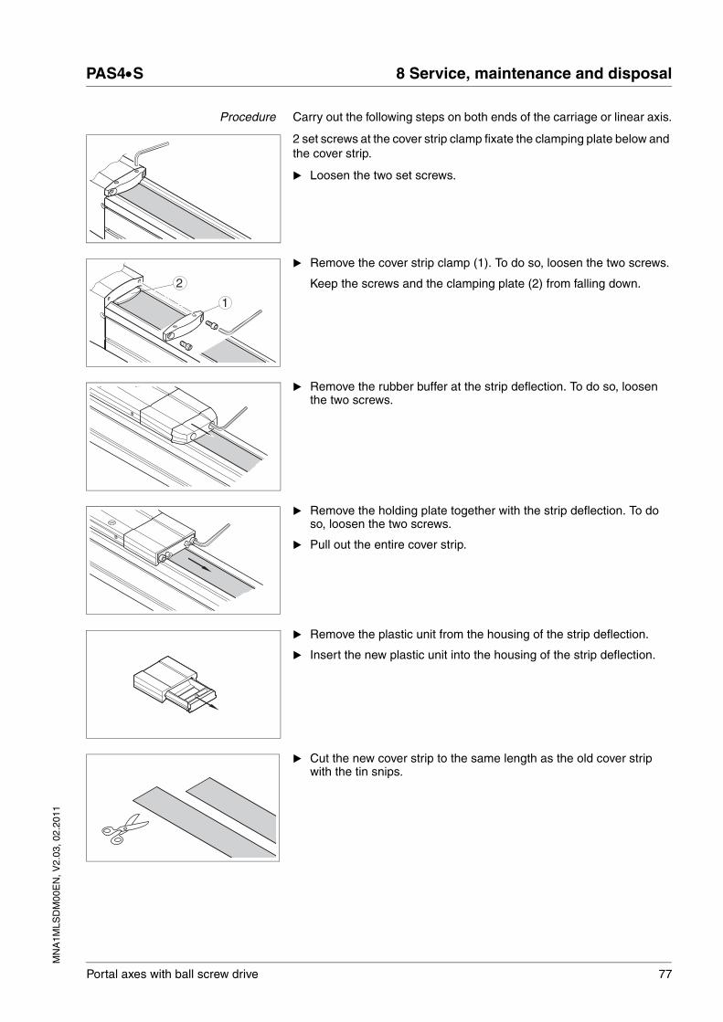
MN
A1M
LSD
M00
EN
, V2.
03, 0
2.20
11
PAS4•S 8 Service, maintenance and disposal
Portal axes with ball screw drive 77
Procedure Carry out the following steps on both ends of the carriage or linear axis.
2 set screws at the cover strip clamp fixate the clamping plate below and the cover strip.
� Loosen the two set screws.
� Remove the cover strip clamp (1). To do so, loosen the two screws.
Keep the screws and the clamping plate (2) from falling down.
� Remove the rubber buffer at the strip deflection. To do so, loosen the two screws.
� Remove the holding plate together with the strip deflection. To do so, loosen the two screws.
� Pull out the entire cover strip.
� Remove the plastic unit from the housing of the strip deflection.
� Insert the new plastic unit into the housing of the strip deflection.
� Cut the new cover strip to the same length as the old cover strip with the tin snips.
2
1

78 Portal axes with ball screw drive
8 Service, maintenance and disposal PAS4•S
MN
A1M
LSD
M00
EN
, V2.
03, 0
2.20
11
� Guide the new cover strip through the guide channel inside the car-riage.
� Guide the new cover strip through the strip deflections.
� Place the holding plate for mounting the rubber buffer into position at the strip deflection.
� Screw the strip deflection into place.
When doing so, align the strip deflection and the carriage.
� Place the cover strip over the entire length of the axis body.
Align the cover strip symmetrically. The distance from the two end blocks should amount to 1 ... 2mm.
Verify that the cover strip has even contact with the magnetic strips.
� Fit the clamping plate (2) into place.
� Screw the cover strip clamp (1) into place with the tightening torque specified in Table 8.1.
� Tighten the two set screws for holding the clamping plate with the tightening torque specified in Table 8.2.
1... 2
2
1

MN
A1M
LSD
M00
EN
, V2.
03, 0
2.20
11
PAS4•S 8 Service, maintenance and disposal
Portal axes with ball screw drive 79
� Mount the rubber buffer with the two screws and the washers.
Test movements � Run initial tests at reduced velocity.
8.4 Maintenance
The maintenance intervals for cleaning and lubrication must be adhered to.
� Include the maintenance intervals in your maintenance plan.
8.4.1 Cleaning
Due to its design, the product is not susceptible to the ingress of con-taminants and external objects. The guide is located inside the axis body and it is covered.
The product must be checked and cleaned at regular intervals.
� Do not use compressed air for cleaning.
� Remove large particles and dirt from the surface at regular inter-vals.
� The anodized surface only has a limited resistance to alkaline cleaning agents. Therefore, use only neutral cleaning agents for cleaning.
� Use only damp, soft and lint-free cleaning cloths to wipe the sur-face.
Cover strip The cover strip is teflon-coated. The friction causes abrasion on the cover strip.
� Remove abrasion products at regular intervals.

80 Portal axes with ball screw drive
8 Service, maintenance and disposal PAS4•S
MN
A1M
LSD
M00
EN
, V2.
03, 0
2.20
11
8.4.2 Lubrication
Lubricant is consumed continuously during operation of the linear axis. The product must be lubricated at regular intervals.
The lubrication system is not completely tight. Therefore, small amounts of lubricants may escape.
Insufficient lubrication or incorrect lubricants increase wear and reduce the service life. The following factors influence the lubrication intervals:
• Dust and dirt particles
• High operating temperatures
• Heavy loads
• Heavy vibration
• Permanent short-distance positioning
• High speed of rotation
CAUTIONDAMAGE DUE TO INCORRECT LUBRICANT
Incorrect lubricants may damage the product.
• Use the correct type of lubricant (grease, oil) as specified.
Failure to follow these instructions can result in equipment dam-age.

MN
A1M
LSD
M00
EN
, V2.
03, 0
2.20
11
PAS4•S 8 Service, maintenance and disposal
Portal axes with ball screw drive 81
8.4.3 Lubricating the linear guide and the drive elements
The ball screw axis is lubricated with grease from an internal reservoir. The reservoir is factory-prefilled. The carriage features 3 grease nipples at each side for relubrication.
• The outer grease nipples are used to lubricate the linear guide.
• The inner grease nipples are used to fill the drive element (ball screw drive).
The lubrication interval depends on the load, the velocity, the cycle time and the ambient conditions. The following recommended values apply to lubrication intervals:
Linear guide • 5000 km operational performance
Drive elements • 100 km at a ball screw pitch of 5 mm
• 200 km at a ball screw pitch of 10 mm
• 300 km at a ball screw pitch of 16 mm
• 400 km at a ball screw pitch of 20 mm
• 500 km at a ball screw pitch of 25 mm
See chapter 7 "Accessories and spare parts" for grease guns, nozzles and lubricants.
Notes on greasing When applying the lubricant, you must not exceed a maximum flow rate. Therefore, the minimum injection time of 3 seconds per grease gun stroke must be adhered to.
The carriage must be moved between strokes of the grease gun to allow the grease to distribute evenly in the lubricant reservoirs.
Size Lubricant 1)
1) Alternative grease K1N-30 as per DIN51825
Relubrication volume Strokes
PAS42 Microlube GL 261 0.3 cm3 1/4
PAS43 Microlube GL 261 0.6 cm3 1 1/4
PAS44 Microlube GL 261 1.0 cm3 2
Size Lubricant 1)
1) Alternative lubricant K1N-30 as per DIN51825
Relubrication volume Strokes
PAS42 Microlube GL 261 1.5 cm3 3
PAS43 Microlube GL 261 3.5 cm3 7
PAS44 Microlube GL 261 4.5 cm3 9

82 Portal axes with ball screw drive
8 Service, maintenance and disposal PAS4•S
MN
A1M
LSD
M00
EN
, V2.
03, 0
2.20
11
Procedure
Lubricating the linear guide
� Inject the correct type and volume of grease into the two outer grease nipples at one side of the carriage.
Lubricating the drive element
� Inject the correct type and volume of grease into the center grease nipple at one side of the carriage.
8.5 Shipping, storage, disposal
Note the ambient conditions on page 21.
Shipping The product must be protected against shocks during transportation. If possible, use the original packaging for shipping.
Storage The product may only be stored in spaces where the specified permis-sible ambient conditions are met.Protect the product from dust and dirt.
Disposal The product consists of various materials that can be recycled. Dispose of the product in accordance with local regulations.

MN
A1M
LSD
M00
EN
, V2.
03, 0
2.20
11
PAS4•S 9 Glossary
Portal axes with ball screw drive 83
99 Glossary
9.1 Units and conversion tables
The value in the specified unit (left column) is calculated for the desired unit (top row) with the formula (in the field).
Example: conversion of 5 meters [m] to yards [yd]5 m / 0.9144 = 5.468 yd
9.1.1 Length
9.1.2 Mass
9.1.3 Force
9.1.4 Power
in ft yd m cm mm
in - / 12 / 36 * 0.0254 * 2.54 * 25.4
ft * 12 - / 3 * 0.30479 * 30.479 * 304.79
yd * 36 * 3 - * 0.9144 * 91.44 * 914.4
m / 0.0254 / 0.30479 / 0.9144 - * 100 * 1000
cm / 2.54 / 30.479 / 91.44 / 100 - * 10
mm / 25.4 / 304.79 / 914.4 / 1000 / 10 -
lb oz slug kg g
lb - * 16 * 0.03108095 * 0.4535924 * 453.5924
oz / 16 - * 1.942559*10-3 * 0.02834952 * 28.34952
slug / 0.03108095 / 1.942559*10-3 - * 14.5939 * 14593.9
kg / 0.45359237 / 0.02834952 / 14.5939 - * 1000
g / 453.59237 / 28.34952 / 14593.9 / 1000 -
lb oz p dyne N
lb - * 16 * 453.55358 * 444822.2 * 4.448222
oz / 16 - * 28.349524 * 27801 * 0.27801
p / 453.55358 / 28.349524 - * 980.7 * 9.807*10-3
dyne / 444822.2 / 27801 / 980.7 - / 100*103
N / 4.448222 / 0.27801 / 9.807*10-3 * 100*103 -
HP W
HP - * 746
W / 746 -

84 Portal axes with ball screw drive
9 Glossary PAS4•S
MN
A1M
LSD
M00
EN
, V2.
03, 0
2.20
11
9.1.5 Rotation
9.1.6 Torque
9.1.7 Moment of inertia
9.1.8 Temperature
9.1.9 Conductor cross section
min-1 (RPM) rad/s deg./s
min-1 (RPM) - * π / 30 * 6
rad/s * 30 / π - * 57.295
deg./s / 6 / 57.295 -
lb·in lb·ft oz·in Nm kp·m kp·cm dyne·cm
lb·in - / 12 * 16 * 0.112985 * 0.011521 * 1.1521 * 1.129*106
lb·ft * 12 - * 192 * 1.355822 * 0.138255 * 13.8255 * 13.558*106
oz·in / 16 / 192 - * 7.0616*10-3 * 720.07*10-6 * 72.007*10-3 * 70615.5
Nm / 0.112985 / 1.355822 / 7.0616*10-3 - * 0.101972 * 10.1972 * 10*106
kp·m / 0.011521 / 0.138255 / 720.07*10-6 / 0.101972 - * 100 * 98.066*106
kp·cm / 1.1521 / 13.8255 / 72.007*10-3 / 10.1972 / 100 - * 0.9806*106
dyne·cm / 1.129*106 / 13.558*106 / 70615.5 / 10*106 / 98.066*106 / 0.9806*106 -
lb·in2 lb·ft2 kg·m2 kg·cm2 kp·cm·s2 oz·in2
lb·in2 - / 144 / 3417.16 / 0.341716 / 335.109 * 16
lb·ft2 * 144 - * 0.04214 * 421.4 * 0.429711 * 2304
kg·m2 * 3417.16 / 0.04214 - * 10*103 * 10.1972 * 54674
kg·cm2 * 0.341716 / 421.4 / 10*103 - / 980.665 * 5.46
kp·cm·s2 * 335.109 / 0.429711 / 10.1972 * 980.665 - * 5361.74
oz·in2 / 16 / 2304 / 54674 / 5.46 / 5361.74 -
°F °C K
°F - (°F - 32) * 5/9 (°F - 32) * 5/9 + 273.15
°C °C * 9/5 + 32 - °C + 273.15
K (K - 273.15) * 9/5 + 32 K - 273.15 -
AWG 1 2 3 4 5 6 7 8 9 10 11 12 13
mm2 42.4 33.6 26.7 21.2 16.8 13.3 10.5 8.4 6.6 5.3 4.2 3.3 2.6
AWG 14 15 16 17 18 19 20 21 22 23 24 25 26
mm2 2.1 1.7 1.3 1.0 0.82 0.65 0.52 0.41 0.33 0.26 0.20 0.16 0.13

MN
A1M
LSD
M00
EN
, V2.
03, 0
2.20
11
PAS4•S 9 Glossary
Portal axes with ball screw drive 85
9.2 Terms and Abbreviations
See chapter 2.5 "Standards and terminology" for information on the per-tinent standards on which many terms are based. Some terms and ab-breviations may have specific meanings with regard to the standards.
Axis body The axis body is aa aluminum precision profile.
Ball screw drive The ball screw drive converts a rotary movement into a linear move-ment. It consists of a ball screw, a ball nut with the ball recirculating el-ements and the bearing balls. A ball screw drive has a very high efficiency. It allows for high-precision, stiff feed movements and gener-ates high feed forces at high positioning accuracy and repeatability.
Ball screw pitch The pitch of the ball screw shaft relates to the distance covered by the carriage per revolution of the ball screw. The greater the pitch the higher the maximum velocity.
The following applies to the ball screw pitch:
• High pitch requires high driving torque
• High pitch results in high velocity
• High pitch causes high inaccuracy
Breakaway torque The breakaway torque describes the driving torque required to over-come the static friction and that initiates the transition to sliding friction.
Buckling stress Buckling is the loss of stability of the ball screw when the maximum per-missible thrust forces whose line of application is along the axis of the ballscrew axis is exceeded. Excessive buckling stress results in a rapidly increasing deformation and deflection of the ballscrew.
Cantilever axis In the case of a cantilever axis, the carriage is stationary while the axis body moves. Portal axes work the other way round.
Critical speed of the ball screw shaft If the critical speed of the ball screw shaft is exceeded, deflection of the ball screw and resonance will occur. This will seriously affect the service life of the ball screw drive. Ball screw supports are installed in longer lin-ear axes to increase the critical speed of the ball screw shaft speed and thus the performance data.
DOM Date of manufacturing: The nameplate of the product shows the date of manufacture in the format DD.MM.YY or in the format DD.MM.YYYY. Ex-ample:31.12.09 corresponds to December 31, 2009 31.12.2009 corresponds to December 31, 2009
Degree of protection The degree of protection is a standardized specification for electrical equipment that describes the protection against the ingress of foreign objects and water (for example: IP 20).
Direction of rotation Rotation of the motor shaft in a positive or negative direction of rotation. Positive direction of rotation is when the motor shaft rotates clockwise as you look at the end of the protruding motor shaft.
Drive element The drive element of the linear axis is a ball screw drive.
Error class Classification of errors into groups. The different error classes allow for specific responses to errors, for example by severity.
Fatal error In the case of fatal error, the product is no longer able to control the mo-tor so that the power stage must be immediately disabled.

86 Portal axes with ball screw drive
9 Glossary PAS4•S
MN
A1M
LSD
M00
EN
, V2.
03, 0
2.20
11
Fault Fault is a state that can be caused by an error. Further information can be found in the pertinent standards such as IEC 61800-7, ODVA Com-mon Industrial Protocol (CIP).
Fault reset A function used to restore the drive to an operational state after a de-tected error is cleared by removing the cause of the error so that the er-ror is no longer active.
Feed per revolution The feed per revolution is the distance the carriage covers per motor rev-olution.
Linear guide The linear guide consists of the guide carriage and the recirculating ball bearing guide.
Load torque The permissible load torques are calculated based on the service life of the carriage guide. If the load torque exceeds the specified values, the service life of the axis will be reduced.
Modulus of elasticity The modulus of elasticity is used to describe the tendency of a material to deform along an axis when opposing forces are applied along this axis; it is the ratio of tensile strain and tensile stress. The higher the value, the stiffer the material.
Mounting position The linear axes can be installed in any desired mounting position. How-ever, all external forces and torques must be within the ranges of per-missible values.
Portal axis In the case of a portal axis, the axis body is stationary while the carriage moves. Cantilever axes work the other way round.
Positioning accuracy Positioning accuracy is the tolerance between the specified position and actual position.
Recirculating ball bearing The axis axis body absorbs the forces and torques applied at the car-riage via the recirculating ball bearing guide. The recirculating ball bear-ing guide can absorb high forces and torques.
Repeatability Repeatability is the accuracy with which it is possible to move to a pre-vious position again under the same conditions.
Running accuracy Due to the manufacturing process, the extruded aluminium profiles have a certain tolerance in terms in straightness and twist. The tolerances are specified in EN 12020-2. To reach the desired running accuracy, the lin-ear axis must be mounted on a precision-machined surface.
Sensor Inductive proximity switches are used as sensors for limit switches or ref-erence switches. These switches are not a safety function.
Service life The service life is the distance in kilometers before the first signs of ma-terial fatigue can be seen on the guides, the drive elements and the bearings. Service life specifications (kilometers covered) relate to the nominal values specified in the data sheet. If the nominal values are ex-ceeded, the service life decreases accordingly.
Stiffness Stiffness is a measure of the ability to move and hold with high position accuracy a part to be positioned even when the load changes.
Stroke reserve The stroke reserve is the distance between a limit switch and the me-chanical stop.
Stroke Stroke is the maximum travel of the carriage between the switching points of the limit switches.
Support axis A support axis has linear guides, but no drive elements. A support axis carries loads that are applied asymmetrically to the carriage and im-proves the stability and service life of the system.
MN
A1M
LSD
M00
EN
, V2.
03, 0
2.20
11
PAS4•S 9 Glossary
Portal axes with ball screw drive 87
Warning If the term is used outside the context of safety instructions, a warning alerts to a potential problem that was detected by a monitoring function. A warning does not cause a transition of the operating state.

88 Portal axes with ball screw drive
9 Glossary PAS4•S
MN
A1M
LSD
M00
EN
, V2.
03, 0
2.20
11

MN
A1M
LSD
M00
EN
, V2.
03, 0
2.20
11
PAS4•S 10 Index
Portal axes with ball screw drive 89
1010 Index
AAbbreviations 85Accessories and spare parts 57Alignment 45Ambient conditions 21
Installation altitude 21Operation 21
Axis body 85
BBall screw drive 85Ball screw pitch 85Before you begin
Safety information 17Breakaway torque 85Buckling stress 85
CCantilever axis 85Commissioning 53
steps 54Connection
Motor 52Cover strip
Replacement 76Critical speed of the ball screw 85
DDegree of protection 21Diagnostics 55Disposal 69, 82Drive element 85
EElastomer coupling 75Elastomer coupling, replacing the 75Electrical installation 52EPLAN Macros 7
FFeed per revolution 86
GGlossary 83
90 Portal axes with ball screw drive
10 Index PAS4•S
MN
A1M
LSD
M00
EN
, V2.
03, 0
2.20
11
HHazard categories 18
IInstallation
electrical 52mechanical 43
Intended use 17Introduction 9IP degree of protection 21
LLinear guide 86Load torque 86Lubricating the linear guide and the drive elements 81
MMacros EPLAN 7Maintenance 69Manuals
Source 7Mechanical installation 43Modulus of elasticity 86Mounting
Contact plate 45Customer application 51Gearbox 48Linear axis 44Motor 48Sensor 46
Mounting position 86
OOperation, ambient temperature 21
PPortal axis 86Positioning accuracy 86
QQualification of personnel 17
RRecirculating ball bearing 86Repeatability 86Replacement
Cover strip 76Sensor 72Strip deflection 76
Replacing the elastomer coupling 75Replacing the motor or the gearbox 73Running accuracy 45, 86

MN
A1M
LSD
M00
EN
, V2.
03, 0
2.20
11
PAS4•S 10 Index
Portal axes with ball screw drive 91
SSensor 86
Replacement 72Service 69Service address 69Service life 86Shipping 82Source
EPLAN Macros 7Manuals 7
Standard tightening torques 43Stiffness 86Storage 82Strip deflection
Replacement 76Stroke 86Stroke reserve 86Support axis 86
TTechnical data 21Temperature during operation 21Terms 85Tightening torques
Standard 43Troubleshooting 55Type code 12
UUnits and conversion tables 83
VVacuum 21