Embed Size (px)
Citation preview

Becker Avionics GmbH • Baden-Airpark B108 • 77836 Rheinmünster • Germany
+49 (0) 7229 / 305-0 • Fax +49 (0) 7229 / 305-217
http://www.becker-avionics.com • E-mail: [email protected]
Portable VHF Stations
GK615-XX GK616-XX
Installation and Operation Manual DV16800.03
Issue 03 August 2015 Article-No. 0633.496-071

Installation and Operation
2 GK61X-XX DV16800.03 Issue 03 08/2015
Preface Dear Customer, Thank you for purchasing this BECKER product. We are pleased that you have chosen our product and we are confident that it will meet your expectations. For development and manufacturing of our product, the guidelines for highest quality and reliability have been borne in mind, supplemented by selection of high quality material, responsible production and testing in accordance to the ISO 9001 and DIN EN 9100 standards. Our competent customer support department will respond on any technical question you may have. Please do not hesitate to contact us at any time.
Portable VHF Stations
GK61X-XX without accessories
Example: GK61X-XX with accessories
Example: GK61X-XX with accessories
Installation and Operation
DV16800.03 Issue 03 08/2015 GK61X-XX 3
First Issue and Changes
Issue 03 August 2015
LIST OF EFFECTIVE PAGES
Page No.: Date: Page No.: Date:
Cover Page 08/2015
Introduction 08/2015
Chapter 1 - 5 08/2015
DV16800.03 / Article Number 0633.496-071
© 2015 by Becker Avionics GmbH / all rights reserved

Installation and Operation
4 GK61X-XX DV16800.03 Issue 03 08/2015
Table of Contents 1. General Description ....................................................................................................................... 9 1.1. Introduction .................................................................................................................................... 9 1.2. Purpose of Equipment ................................................................................................................. 10 1.3. Variants Overview ....................................................................................................................... 10
1.3.1. Variants Overview Portable VHF Station .......................................................................... 11 1.4. Safety-Conscious Utilization ........................................................................................................ 12 1.5. Technical Data ............................................................................................................................. 13
1.5.1. Electrical Characteristics ................................................................................................... 13 1.5.2. Dimensions & Weight ........................................................................................................ 13 1.5.3. Software ............................................................................................................................ 13 1.5.4. Complex Hardware ........................................................................................................... 13 1.5.5. Approvals .......................................................................................................................... 14
1.6. Order Code .................................................................................................................................. 15 1.6.1. GK61X ............................................................................................................................... 15 1.6.2. Accessories and Spare Parts ............................................................................................ 15
2. Installation .................................................................................................................................... 17 2.1. Packaging, Transport, Storage .................................................................................................... 17
2.1.1. Packaging Material and Transport .................................................................................... 17 2.2. Device Assignment ...................................................................................................................... 18
2.2.1. Scope of Delivery .............................................................................................................. 18 2.2.2. Additional Required Equipment......................................................................................... 18 2.2.3. Type Plate ......................................................................................................................... 19
2.3. Mounting Requirements .............................................................................................................. 20 2.3.1. Installation in a Vehicle ..................................................................................................... 20
2.4. Dimensions .................................................................................................................................. 21 2.4.1. GK61X-XX ......................................................................................................................... 21 2.4.2. Drilling Template for Vehicle Mounting ............................................................................. 22 2.4.3. Car Mounting Bracket and Handle GK61X-XX ................................................................. 23
2.5. Connector Pin Assignments ........................................................................................................ 23 2.5.1. Connector P2 .................................................................................................................... 24 2.5.2. Antenna Connection for Installation in a Vehicle ............................................................... 24 2.5.3. Connect an External PTT or Foot PTT Switch .................................................................. 24
3. Operating Instructions ................................................................................................................ 25 3.1. Device Description....................................................................................................................... 25
3.1.1. Device Assignment ........................................................................................................... 26 3.1.2. Packing, Transport, Storage ............................................................................................. 26 3.1.3. Scope of Delivery .............................................................................................................. 26 3.1.4. Type Plate ......................................................................................................................... 26 3.1.5. Controls and Indications .................................................................................................... 26
3.2. Start-Up ....................................................................................................................................... 28 3.3. Receive and Transmit Mode ....................................................................................................... 28
3.3.1. Receive Mode ................................................................................................................... 28 3.3.2. Transmit Mode .................................................................................................................. 29
3.4. Frequency Selection Modes ........................................................................................................ 29 3.4.1. Standard Mode .................................................................................................................. 30 3.4.2. Direct Tune Mode .............................................................................................................. 31 3.4.3. Channel Mode ................................................................................................................... 32 3.4.4. Frequency Storage Functions ........................................................................................... 33 3.4.5. Automatic Storage Function .............................................................................................. 34 3.4.6. Scan Mode ........................................................................................................................ 34
3.5. SQUELCH ................................................................................................................................... 35 3.6. RX Field Strength Indication ........................................................................................................ 35 3.7. Channel Spacing Mode ............................................................................................................... 35
Installation and Operation
DV16800.03 Issue 03 08/2015 GK61X-XX 5
3.8. Auxiliary Audio Input ................................................................................................................... 36 3.9. Intercom Operation ..................................................................................................................... 36 3.10. VOX & Speaker Operation .......................................................................................................... 37 3.11. Menus .......................................................................................................................................... 37
3.11.1. Intercom Menu .................................................................................................................. 37 3.11.2. Pilots Menu ....................................................................................................................... 39
3.12. Warning and Failure Indications ................................................................................................. 40 4. Certifications ................................................................................................................................ 43 4.1. BAF Approval - GT6201 .............................................................................................................. 44 4.2. EC Declaration of Conformity – GT6201-05 ............................................................................... 46 4.3. EC Declaration of Conformity – GT6201-10 ............................................................................... 48 4.4. European Technical Standard Order (ETSO) Authorisation ....................................................... 50 5. Index ............................................................................................................................................. 52 Fig. 1 GK61X-XX with microphone 1PM415-1 ....................................................................................................... 11 Fig. 2 GK61X-XX with microphone 1PH01 ............................................................................................................ 11 Fig. 3 Type plate (example) ................................................................................................................................... 19 Fig. 4 Dimensions GK61X-XX ................................................................................................................................ 21 Fig. 5 Drilling template GK61X-XX for vehicle mounting bracket (no scale drawing) ............................................. 22 Fig. 6 Car mounting bracket and handle GK61X-XX .............................................................................................. 23 Fig. 7 GK61X rear side .......................................................................................................................................... 23 Fig. 8 Wiring diagram Connector P2 ...................................................................................................................... 24 Fig. 9 Wiring diagram 5 way DIN socket J4 ........................................................................................................... 24 Fig. 10 Controls GK61X-XX ................................................................................................................................... 26 Fig. 11 Controls and indicators AR6201/GT6201................................................................................................... 27
List of Abbreviations List of Abbreviations
approx. approximately
AC Advisory Circular
FAA Federal Aviation Administration
HW Hardware
PBIT Power-On Built In Test
PTT Push To Talk
SW Software
TX Transmit
VHF Very High Frequency
Units Units
A Ampere
mA Milliampere
°C Degree Celsius
cm Centimetre
cd/m2 Candela Per Square Meter (1 cd/m2 = 1 nit)
Installation and Operation
6 GK61X-XX DV16800.03 Issue 03 08/2015
Units
dBm Power Ratio In Decibel
dB Decibel
g Gram
kg Kilogram
kHz Kilohertz
MHz Megahertz
mm Millimetre
Nm Newton metre
Ohm (Ω) Resistance
s Second
V Volt
mV Millivolt
W Watt
mW Milliwatt
" Inch
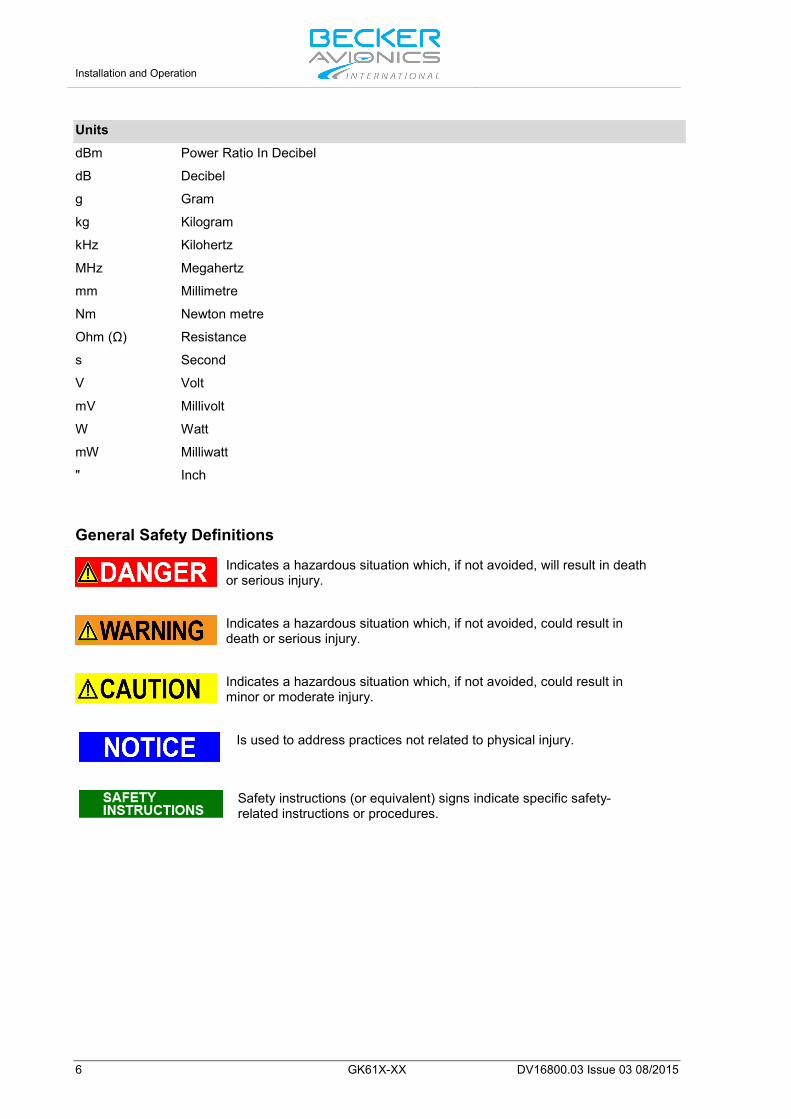
General Safety Definitions
Indicates a hazardous situation which, if not avoided, will result in death or serious injury.
Indicates a hazardous situation which, if not avoided, could result in death or serious injury.
Indicates a hazardous situation which, if not avoided, could result in minor or moderate injury.
Is used to address practices not related to physical injury.
Safety instructions (or equivalent) signs indicate specific safety-related instructions or procedures.
Installation and Operation
DV16800.03 Issue 03 08/2015 GK61X-XX 7
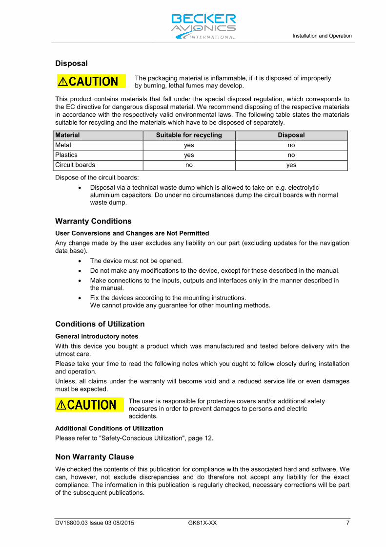
Disposal
The packaging material is inflammable, if it is disposed of improperly by burning, lethal fumes may develop.
This product contains materials that fall under the special disposal regulation, which corresponds to the EC directive for dangerous disposal material. We recommend disposing of the respective materials in accordance with the respectively valid environmental laws. The following table states the materials suitable for recycling and the materials which have to be disposed of separately. Material Suitable for recycling Disposal Metal yes no Plastics yes no Circuit boards no yes Dispose of the circuit boards:
• Disposal via a technical waste dump which is allowed to take on e.g. electrolytic aluminium capacitors. Do under no circumstances dump the circuit boards with normal waste dump.
Warranty Conditions User Conversions and Changes are Not Permitted Any change made by the user excludes any liability on our part (excluding updates for the navigation data base).
• The device must not be opened. • Do not make any modifications to the device, except for those described in the manual. • Make connections to the inputs, outputs and interfaces only in the manner described in
the manual. • Fix the devices according to the mounting instructions.
We cannot provide any guarantee for other mounting methods.
Conditions of Utilization General introductory notes With this device you bought a product which was manufactured and tested before delivery with the utmost care. Please take your time to read the following notes which you ought to follow closely during installation and operation. Unless, all claims under the warranty will become void and a reduced service life or even damages must be expected.
The user is responsible for protective covers and/or additional safety measures in order to prevent damages to persons and electric accidents.
Additional Conditions of Utilization Please refer to "Safety-Conscious Utilization", page 12.
Non Warranty Clause We checked the contents of this publication for compliance with the associated hard and software. We can, however, not exclude discrepancies and do therefore not accept any liability for the exact compliance. The information in this publication is regularly checked, necessary corrections will be part of the subsequent publications.

Installation and Operation
8 GK61X-XX DV16800.03 Issue 03 08/2015
Blank Page
General Description
Introduction
DV16800.03 Issue 03 08/2015 GK61X-XX 9
1. General Description In this chapter you can read about: 1.1. Introduction.................................................................................................................................... 9 1.2. Purpose of Equipment ................................................................................................................. 10 1.3. Variants Overview ....................................................................................................................... 10
1.3.1. Variants Overview Portable VHF Station .......................................................................... 11 1.4. Safety-Conscious Utilization ....................................................................................................... 12 1.5. Technical Data ............................................................................................................................ 13
1.5.1. Electrical Characteristics................................................................................................... 13 1.5.2. Dimensions & Weight........................................................................................................ 13 1.5.3. Software ............................................................................................................................ 13 1.5.4. Complex Hardware ........................................................................................................... 13 1.5.5. Approvals .......................................................................................................................... 14
1.6. Order Code.................................................................................................................................. 15 1.6.1. GK61X .............................................................................................................................. 15 1.6.2. Accessories and Spare Parts ........................................................................................... 15
1.1. Introduction The easily-portable VHF station GK61X-XX can be used e.g. for mobile and fixed operations on airfields or landing strips. It can also be used in hot air balloons, for ferrying aircraft or recovery of gliders. The portable VHF station consists of the carrying case and one of the available transceivers "Table 1 Variants Overview", page 11. For further descriptions we are using the term GK61X for the VHF Station instead writing the complete model number. The manual "Installation and Operation” (I&O) contain the following sections:
Section DV 16800.03
I&O
General X
Installation X
Operation X
Certifications X
General Description Purpose of Equipment
10 GK61X-XX DV16800.03 Issue 03 08/2015
1.2. Purpose of Equipment The carrying case contains the batteries, speaker, antenna socket, the 5 way DIN socket for the microphone or microphone speaker and the voltage converter. A microphone, a headset or a helmet (ultra light) can be connected to the 5 way DIN socket. The built-in battery is a maintenance-free rechargeable dry lead acid battery 12 V/2 Ah (the number of the built-in batteries depends on the model). The transmitter power is approximately 5...7 W at 12 V and 10 W at 24 V supply voltage. The battery can be charged via the ext. DC socket. The charging voltage can vary between 10...32 V. The charging time for a complete discharged battery is approximately 8 hours. The nominal operating time for the portable VHF station is approximately 6 hours at a keying ratio of 1:10 (normal radio traffic) and a transmit output power of 5 W. Reception is still guaranteed for ca. two further hours. The transceiver contains a monitoring stage for the battery voltage which is activated when the unit is switched on. "LOW BATT" is indicated (appearance about every 5 seconds) if the supply voltage of the transceiver is below the threshold defined in the installation setup. The transceiver is still operable. Depending on the supply voltage the transceiver may have a reduced performance. The portable VHF station is ready for operation after the antenna is connected and the microphone plugged in.
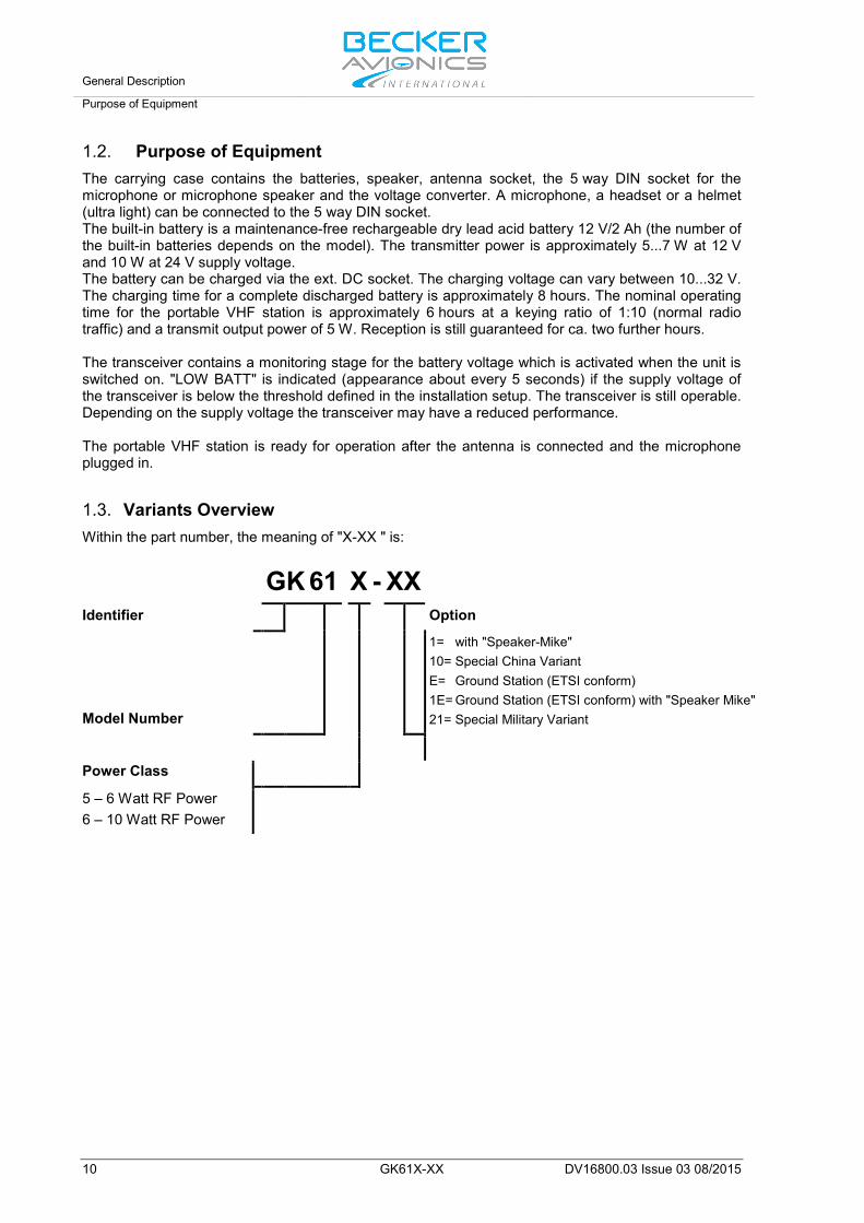
1.3. Variants Overview Within the part number, the meaning of "X-XX " is:
GK 61 X - XX
Identifier Option
Model Number
1= with "Speaker-Mike" 10= Special China Variant E= Ground Station (ETSI conform) 1E= Ground Station (ETSI conform) with "Speaker Mike" 21= Special Military Variant
Power Class
5 – 6 Watt RF Power 6 – 10 Watt RF Power

General Description
Variants Overview
DV16800.03 Issue 03 08/2015 GK61X-XX 11
1.3.1. Variants Overview Portable VHF Station
Fig. 1 GK61X-XX with microphone 1PM415-1
Fig. 2 GK61X-XX with microphone 1PH01
Application Version Transceiver Microphone Antenna Remark
6 W
att T
rans
ceiv
er Airborne
GK615 0622.834-923
AR6201-(022)
1PM415-1 0603.120-350
1A415 0884.294-952
whip antenna and dynamic microphone
GK615-1 0622.842-923
AR6201-(022)
1PH012 0498.475-951
1A415 0884.294-952
whip antenna and speaker microphone
Ground
GK615-E 0638.481-923
GT6201-05 1PM415-1 0603.120-350
1A415 0884.294-952
whip antenna and dynamic microphone
GK615-1E 0638.498-923
GT6201-05 1PH012 0498.475-951
1A415 0884.294-952
whip antenna and speaker microphone
10 W
att T
rans
ceiv
er
Airborne
GK616 0638.463-923
AR6201-(012)
1PM415-1 0603.120-350
1A415 0884.294-952
whip antenna and dynamic microphone
GK616-1 0638.471-923
AR6201-(012)
1PH012 0498.475-951
1A415 0884.294-952
whip antenna and speaker microphone
Ground
GK616-E 0638.501-923
GT6201-10 1PM415-1 0603.120-350
1A415 0884.294-952
whip antenna and dynamic microphone
GK616-1E 0638.511-923
GT6201-10 1PH012 0498.475-951
1A415 0884.294-952
whip antenna and speaker microphone
Special Mission
GK616-21 0637.289-923
AR6201-(021) 1PH012
0498.475-951 1A415-1 0586.137-375
Olive green housing, steel band antenna and speaker microphone
Table 1 Variants Overview

General Description Safety-Conscious Utilization
12 GK61X-XX DV16800.03 Issue 03 08/2015
1.4. Safety-Conscious Utilization
The following notes should always be taken in account to ensure a safe and normal operation of our product.
• Before first use, the built-in battery should be charged for approx. 8...10 hours. Man-carried GK61X-XX can be charged via the included battery charger; for car installations the battery will be recharged automatically via the Car Battery Cable 1KA615 (accessory, to be ordered separately) as soon as the car power supply is available.
• To assure long battery life the GK61X-XX should not be stored in a discharged state for a longer time.
• Speak loud into the microphone and keep it always close to the lips, otherwise ambient noise can be intrusive and make understanding difficult.
• Use only microphones or headsets, which are suitable for ground-stations. Radiation received from the equipment antenna can affect the integrated amplifier of the microphone (feedback). This is noticeable in the receiving station by whistling and/or heavy distortion. The described disturbances can occur in different ways on different transmit channels.
• Transmit buttons can stick, or TX line is short circuited thus causing continuous carrier signal on the active channel. Therefore ensure that the display (sign "TX") disappeared when the "PTT" button was released.
Long term and very close exposure of a human body to VHF radiation may in individual cases cause health issues.
General Description
Technical Data
DV16800.03 Issue 03 08/2015 GK61X-XX 13
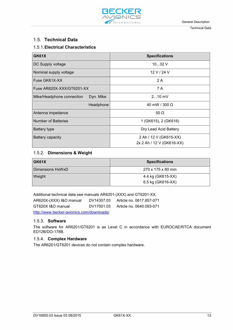
1.5. Technical Data 1.5.1. Electrical Characteristics GK61X Specifications
DC Supply voltage 10...32 V
Nominal supply voltage 12 V / 24 V
Fuse GK61X-XX 2 A
Fuse AR620X-XXX/GT6201-XX 7 A
Mike/Headphone connection Dyn. Mike 2...10 mV
Headphone 40 mW / 300 Ω
Antenna impedance 50 Ω
Number of Batteries 1 (GK615), 2 (GK616)
Battery type Dry Lead Acid Battery
Battery capacity 2 Ah / 12 V (GK615-XX) 2x 2 Ah / 12 V (GK616-XX)
1.5.2. Dimensions & Weight GK61X Specifications
Dimensions HxWxD 270 x 175 x 80 mm
Weight 4.4 kg (GK615-XX) 6.5 kg (GK616-XX)
Additional technical data see manuals AR6201-(XXX) and GT6201-XX. AR620X-(XXX) I&O manual DV14307.03 Article no. 0617.857-071 GT620X I&O manual DV17001.03 Article no. 0640.093-071 http://www.becker-avionics.com/downloads/
1.5.3. Software The software for AR6201/GT6201 is as Level C in accordance with EUROCAE/RTCA document ED12B/DO-178B.
1.5.4. Complex Hardware The AR6201/GT6201 devices do not contain complex hardware.
General Description Technical Data
14 GK61X-XX DV16800.03 Issue 03 08/2015
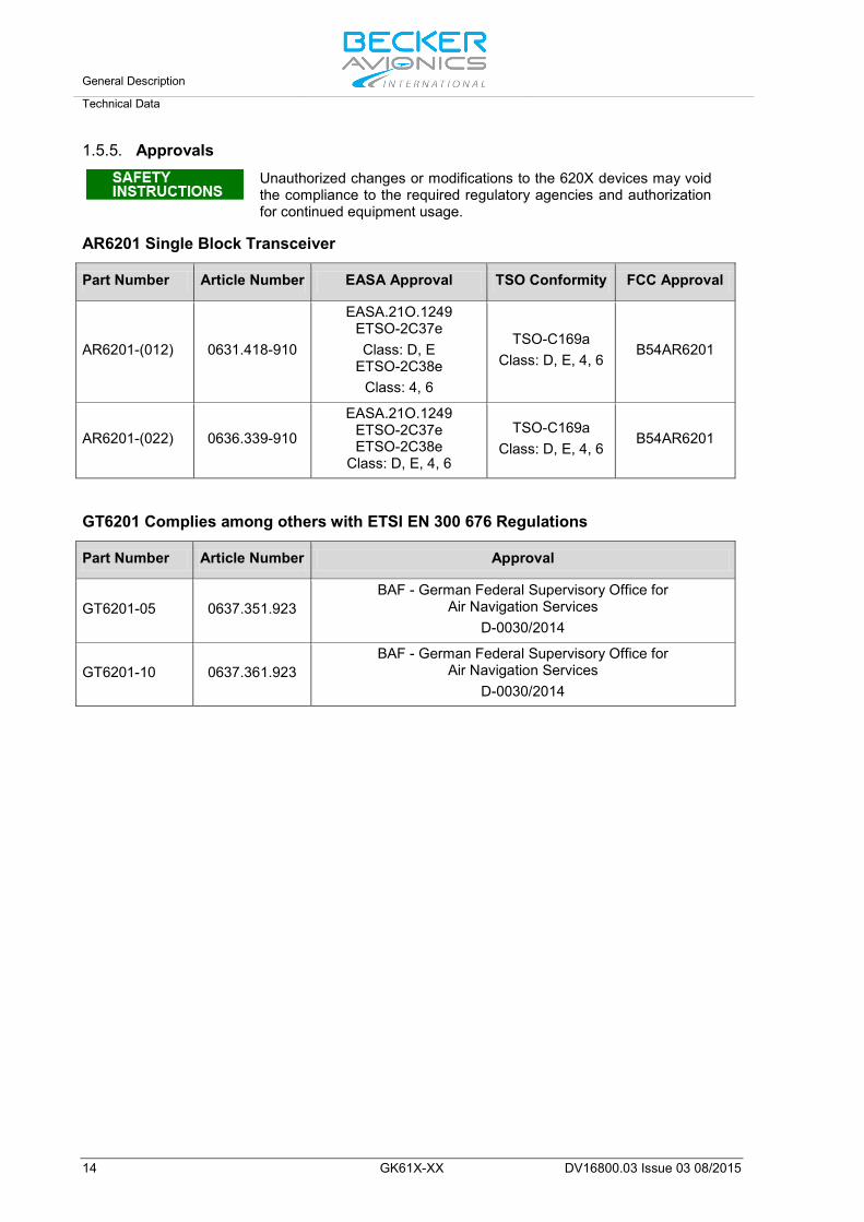
1.5.5. Approvals
Unauthorized changes or modifications to the 620X devices may void the compliance to the required regulatory agencies and authorization for continued equipment usage.
AR6201 Single Block Transceiver
Part Number Article Number EASA Approval TSO Conformity FCC Approval
AR6201-(012) 0631.418-910
EASA.21O.1249 ETSO-2C37e Class: D, E
ETSO-2C38e Class: 4, 6
TSO-C169a Class: D, E, 4, 6
B54AR6201
AR6201-(022) 0636.339-910
EASA.21O.1249 ETSO-2C37e ETSO-2C38e
Class: D, E, 4, 6
TSO-C169a Class: D, E, 4, 6
B54AR6201
GT6201 Complies among others with ETSI EN 300 676 Regulations
Part Number Article Number Approval
GT6201-05 0637.351.923 BAF - German Federal Supervisory Office for
Air Navigation Services D-0030/2014
GT6201-10 0637.361.923 BAF - German Federal Supervisory Office for
Air Navigation Services D-0030/2014
General Description
Order Code
DV16800.03 Issue 03 08/2015 GK61X-XX 15
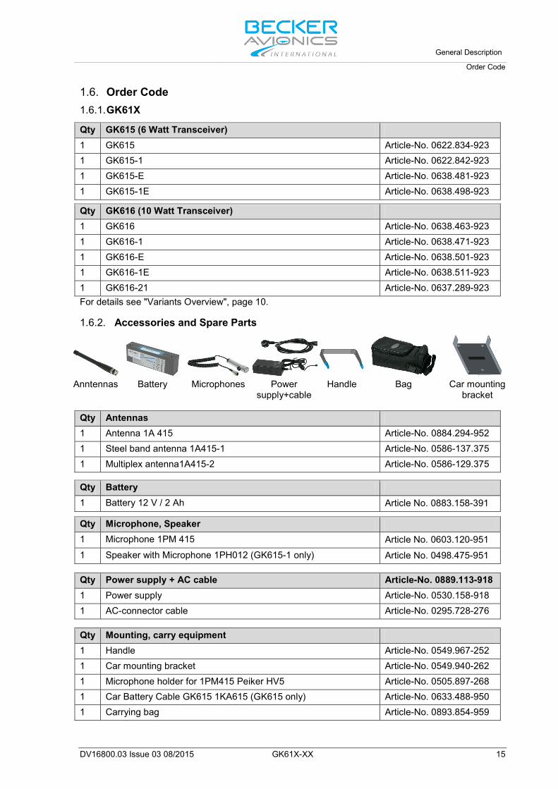
1.6. Order Code 1.6.1. GK61X Qty GK615 (6 Watt Transceiver) 1 GK615 Article-No. 0622.834-923 1 GK615-1 Article-No. 0622.842-923 1 GK615-E Article-No. 0638.481-923 1 GK615-1E Article-No. 0638.498-923 Qty GK616 (10 Watt Transceiver) 1 GK616 Article-No. 0638.463-923 1 GK616-1 Article-No. 0638.471-923 1 GK616-E Article-No. 0638.501-923 1 GK616-1E Article-No. 0638.511-923 1 GK616-21 Article-No. 0637.289-923 For details see "Variants Overview", page 10.
1.6.2. Accessories and Spare Parts
Anntennas Battery Microphones Power
supply+cable Handle Bag Car mounting
bracket Qty Antennas 1 Antenna 1A 415 Article-No. 0884.294-952 1 Steel band antenna 1A415-1 Article-No. 0586-137.375 1 Multiplex antenna1A415-2 Article-No. 0586-129.375 Qty Battery 1 Battery 12 V / 2 Ah Article No. 0883.158-391 Qty Microphone, Speaker 1 Microphone 1PM 415 Article No. 0603.120-951 1 Speaker with Microphone 1PH012 (GK615-1 only) Article No. 0498.475-951 Qty Power supply + AC cable Article-No. 0889.113-918 1 Power supply Article-No. 0530.158-918 1 AC-connector cable Article-No. 0295.728-276 Qty Mounting, carry equipment 1 Handle Article-No. 0549.967-252 1 Car mounting bracket Article-No. 0549.940-262 1 Microphone holder for 1PM415 Peiker HV5 Article-No. 0505.897-268 1 Car Battery Cable GK615 1KA615 (GK615 only) Article-No. 0633.488-950 1 Carrying bag Article-No. 0893.854-959
General Description Order Code
16 GK61X-XX DV16800.03 Issue 03 08/2015
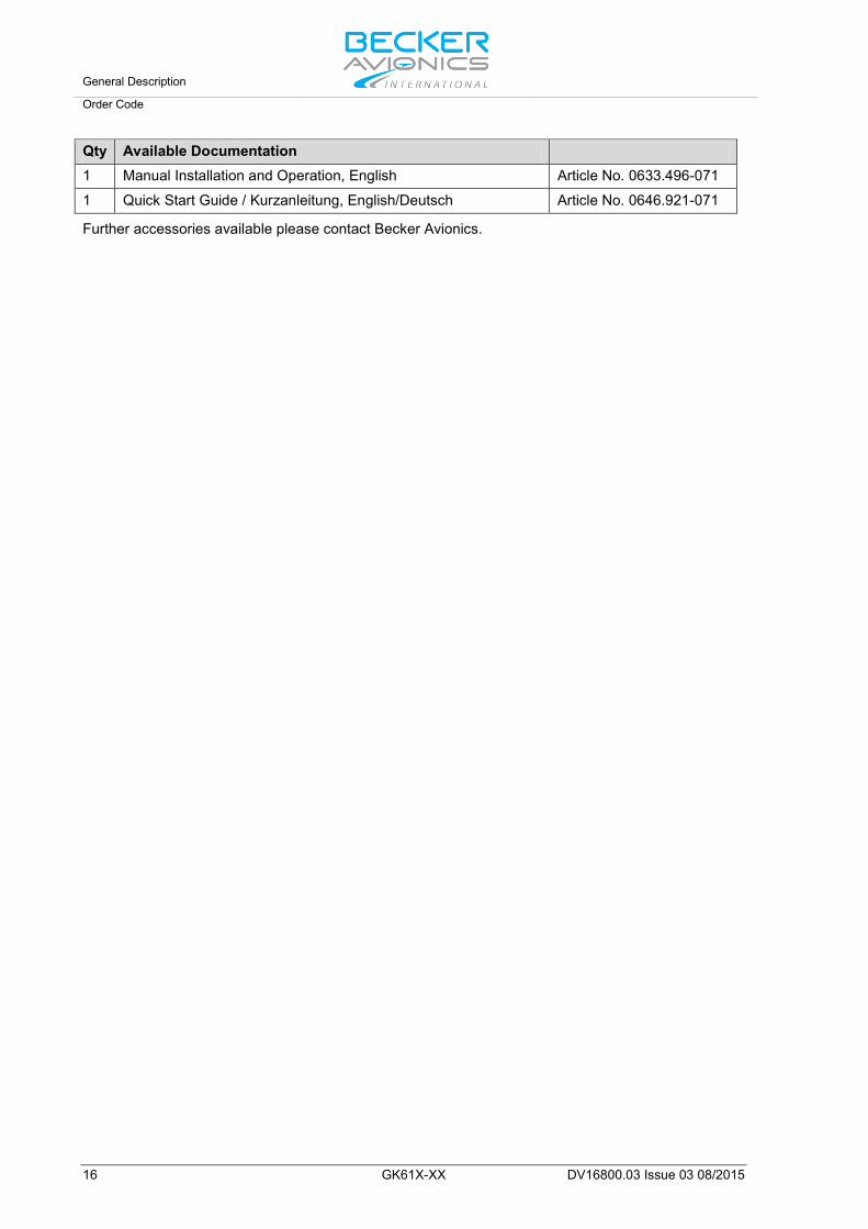
Qty Available Documentation 1 Manual Installation and Operation, English Article No. 0633.496-071
1 Quick Start Guide / Kurzanleitung, English/Deutsch Article No. 0646.921-071 Further accessories available please contact Becker Avionics.
Installation
Packaging, Transport, Storage
DV16800.03 Issue 03 08/2015 GK61X-XX 17
2. Installation This manual must be available close to the device during the performance of all tasks. Careful planning should be applied to achieve the desired performance and reliability from the product. Any deviations from the installation instructions prescribed in this document are under your own responsibility. The installation of the portable VHF station depends on the type of vehicle and equipment design. It is therefore only possible to provide general guidelines in this section.
In this chapter you can read about: 2.1. Packaging, Transport, Storage ................................................................................................... 17
2.1.1. Packaging Material and Transport .................................................................................... 17 2.2. Device Assignment ..................................................................................................................... 18
2.2.1. Scope of Delivery .............................................................................................................. 18 2.2.2. Additional Required Equipment ........................................................................................ 18 2.2.3. Type Plate ......................................................................................................................... 19
2.3. Mounting Requirements .............................................................................................................. 20 2.3.1. Installation in a Vehicle ..................................................................................................... 20
2.4. Dimensions.................................................................................................................................. 21 2.4.1. GK61X-XX ........................................................................................................................ 21 2.4.2. Drilling Template for Vehicle Mounting ............................................................................. 22 2.4.3. Car Mounting Bracket and Handle GK61X-XX ................................................................. 23
2.5. Connector Pin Assignments ........................................................................................................ 23 2.5.1. Connector P2 .................................................................................................................... 24 2.5.2. Antenna Connection for Installation in a Vehicle ............................................................... 24 2.5.3. Connect an External PTT or Foot PTT Switch .................................................................. 24
2.1. Packaging, Transport, Storage Visually inspect the package contents for signs of transport damage.
2.1.1. Packaging Material and Transport
The packaging material is inflammable, if it is disposed of improperly by burning, lethal fumes may develop.
The packaging material can be kept and reused in the case of a return shipment. Improper or faulty packaging may lead to transport damages. Make sure to transport the device always in a safe manner and with the aid of suitable lifting equipment if necessary. Do never use the electric connections for lifting. Before the transport, a clean, level surface should be prepared to place the device on. The electric connections may not be damaged when placing the device.
First Device Checkup • Check the device for signs of transport damages. • Please verify if the indications on the type plate correspond to your purchase order. • Check if the equipment is complete ("Scope of Delivery", page 18).
Storage If you do not wish to mount and install the device immediately, make sure to store it in a dry and clean environment. Make sure that the device is not stored near strong heat sources and that no metal chippings can get into the device.
The batteries have a self-discharging of approx. 1% per day. We recommend to recharge the batteries every 3 month of storage. Use delivered power supply+cable.
Installation Device Assignment
18 GK61X-XX DV16800.03 Issue 03 08/2015
2.2. Device Assignment This manual is valid for the following devices:
• GK615-XX + supplement • GK616-XX + supplement
2.2.1. Scope of Delivery • Manuals
o Installation&Operation • Device in accordance with your order
o VHF transceiver (type depending on GK61X model), o Battery 12 V / 2 Ah (with GK616 models two batteries), o Microphone or o Speaker with microphone (GK615 only), o Antenna 1A 415 o Power supply and AC-connector cable
• Device accessories o Handle o Car mounting bracket o Carrying bag
• Documents of Certifications if available
2.2.2. Additional Required Equipment • Connector kits. • Cable harness.
Details see "Order Code", page 15.

Installation
Device Assignment
DV16800.03 Issue 03 08/2015 GK61X-XX 19
2.2.3. Type Plate The device type is defined by the type plate (on the housing): Example:
Fig. 3 Type plate (example)
Explanation: PN: Example Type designation: GK61X-XX
GK615 = 6 Watt Transceiver GK616 = 10 Watt Transceiver
Options: 1 with "Speaker-Mike" 10 available for China only (10 W) E Ground Station (ETSI conform) 1E Ground Station (ETSI conform) with "Speaker Mike" 21 Special Military Variant
SN: Unique number of the particular device
AN: Article number
DoM: Date of Manufacturing
Software: Corresponding to the displayed version
Compliance and Certifications Corresponding to the displayed text and logos

Installation Mounting Requirements
20 GK61X-XX DV16800.03 Issue 03 08/2015
2.3. Mounting Requirements
The device must not be opened. When installing the device, make sure the heat dissipator of the device receive sufficient air. Keep an efficient distance of the devices with integrated ventilator fans in order to ensure free circulation of the cooling air. Make sure that the mounting plate is not exposed to external temperature influences. Wiring: The following general precautions are to be observed.
• All electrical systems in the vehicle shall be switched off and screened.
• No other leads should be included in the supply lead loop. • All cable terminations to the equipment shall be marked. • The cable harness must be able to move freely and thus
prevent fracture of the wires. It should also be placed in a manner that the individual cables are not abraded on the cabinet or chassis.
• Twisted, screened cables should be used for symmetrical connections to minimise interference from electrical and magnetic fields.
2.3.1. Installation in a Vehicle • Please use the car mounting bracket for installation. • Make sure to find a suitable spot to place the three bolts. • Please check easy access to the controls and indicators of the GK61X-XX. • Detailed information please see "Dimensions", page 21.

Installation
Dimensions
DV16800.03 Issue 03 08/2015 GK61X-XX 21
2.4. Dimensions 2.4.1. GK61X-XX
Dimensions mm (inch)
Fig. 4 Dimensions GK61X-XX

Installation Dimensions
22 GK61X-XX DV16800.03 Issue 03 08/2015
2.4.2. Drilling Template for Vehicle Mounting Dimensions mm (inch)
No scale drawing
Fig. 5 Drilling template GK61X-XX for vehicle mounting bracket (no scale drawing)
Installation
Connector Pin Assignments
DV16800.03 Issue 03 08/2015 GK61X-XX 23
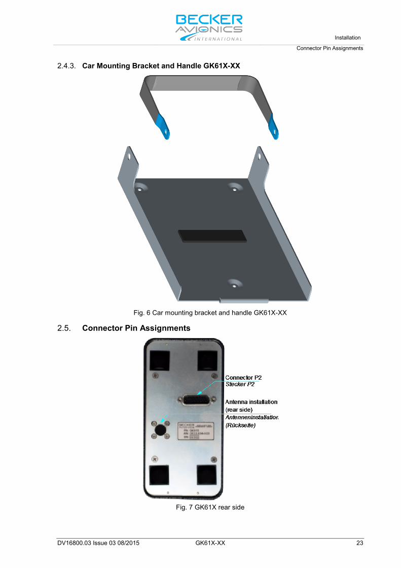
2.4.3. Car Mounting Bracket and Handle GK61X-XX
Fig. 6 Car mounting bracket and handle GK61X-XX
2.5. Connector Pin Assignments
Fig. 7 GK61X rear side
Installation Connector Pin Assignments
24 GK61X-XX DV16800.03 Issue 03 08/2015
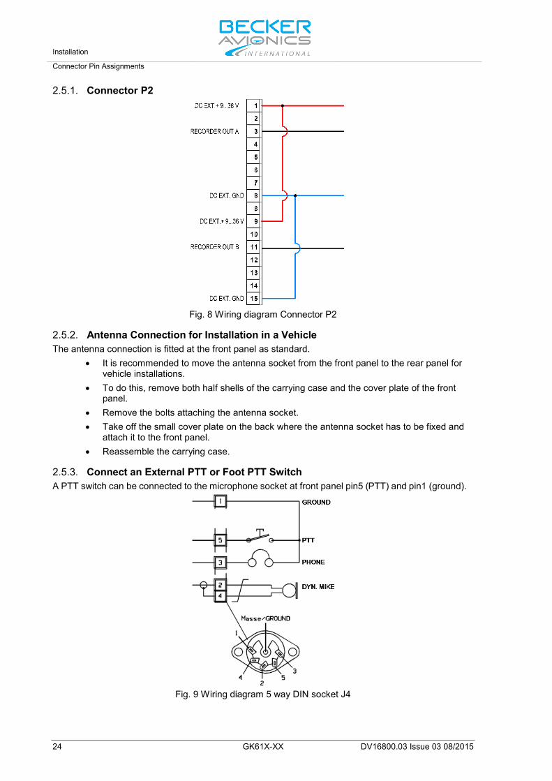
2.5.1. Connector P2
Fig. 8 Wiring diagram Connector P2
2.5.2. Antenna Connection for Installation in a Vehicle The antenna connection is fitted at the front panel as standard.
• It is recommended to move the antenna socket from the front panel to the rear panel for vehicle installations.
• To do this, remove both half shells of the carrying case and the cover plate of the front panel.
• Remove the bolts attaching the antenna socket. • Take off the small cover plate on the back where the antenna socket has to be fixed and
attach it to the front panel. • Reassemble the carrying case.
2.5.3. Connect an External PTT or Foot PTT Switch A PTT switch can be connected to the microphone socket at front panel pin5 (PTT) and pin1 (ground).
Fig. 9 Wiring diagram 5 way DIN socket J4
Operating Instructions
Device Description
DV16800.03 Issue 03 08/2015 GK61X-XX 25
3. Operating Instructions In this chapter you can read about: 3.1. Device Description ...................................................................................................................... 25
3.1.1. Device Assignment ........................................................................................................... 26 3.1.2. Packing, Transport, Storage ............................................................................................. 26 3.1.3. Scope of Delivery .............................................................................................................. 26 3.1.4. Type Plate ......................................................................................................................... 26 3.1.5. Controls and Indications ................................................................................................... 26
3.2. Start-Up ....................................................................................................................................... 28 3.3. Receive and Transmit Mode ....................................................................................................... 28
3.3.1. Receive Mode ................................................................................................................... 28 3.3.2. Transmit Mode .................................................................................................................. 29
3.4. Frequency Selection Modes........................................................................................................ 29 3.4.1. Standard Mode ................................................................................................................. 30 3.4.2. Direct Tune Mode ............................................................................................................. 31 3.4.3. Channel Mode ................................................................................................................... 32
3.4.3.1. Select Channels: ................................................................................................... 32 3.4.4. Frequency Storage Functions ........................................................................................... 33
3.4.4.1. Store ...................................................................................................................... 33 3.4.5. Automatic Storage Function ............................................................................................. 34
3.4.5.1. Delete data: ........................................................................................................... 34 3.4.6. Scan Mode ........................................................................................................................ 34
3.5. SQUELCH ................................................................................................................................... 35 3.6. RX Field Strength Indication ....................................................................................................... 35 3.7. Channel Spacing Mode ............................................................................................................... 35 3.8. Auxiliary Audio Input ................................................................................................................... 36 3.9. Intercom Operation ..................................................................................................................... 36 3.10. VOX & Speaker Operation .......................................................................................................... 37 3.11. Menus .......................................................................................................................................... 37
3.11.1. Intercom Menu .................................................................................................................. 37 3.11.2. Pilots Menu ....................................................................................................................... 39
3.12. Warning and Failure Indications ................................................................................................. 40
3.1. Device Description The chapter "Operating Instructions" in this manual contains general information and instructions to ensure safe operation of the VHF station.
In this section the figures for illustrating display content mainly show transceivers working in 8.33/25 kHz mixed mode. Dedicated pictures for 25 kHz mode are not explicitly shown (they differ only in number of digits for frequency).

Operating Instructions Device Description
26 GK61X-XX DV16800.03 Issue 03 08/2015
3.1.1. Device Assignment This manual is valid for the following devices:
• See page 18
3.1.2. Packing, Transport, Storage • See page 17
3.1.3. Scope of Delivery
• See page 18
3.1.4. Type Plate • See page 19
3.1.5. Controls and Indications
Fig. 10 Controls GK61X-XX

Operating Instructions
Device Description
DV16800.03 Issue 03 08/2015 GK61X-XX 27
Fig. 11 Controls and indicators AR6201/GT6201
Symbol Description Main Function
1
IC/SQL (Intercom/Squelch)
"Short press" during normal operation toggles the RX -SQL ON/OFF. "Long press" during normal operation activates Intercom Menu.
2
MDE (Mode)
"Short press" during normal operation changes the frequency selection mode. "Long press" during normal operation activates the pilots menu.
3
STO (Store)
"Short press" during normal operation activates storage procedure.
4
↨/SCN (Exchange/SCAN)
"Short press" during standard mode, or scan mode toggles between preset and active frequency. "Long press" activates scan mode.
5
Power ON/OFF, Volume Knob
Switches the transceiver ON/OFF and adjusts volume level of received signal.
6
Rotary encoder Turning "ROTARY ENCODER" changes the settings of several parameters (frequency, IC-volume, VOX, …). Pushing the "ROTARY ENCODER" toggles between the digits and acts as an enter key.
-8/25- Change of Channel Spacing
Keeping the MOD and STO button pressed simultaneously longer than 2 seconds changes 8.33 to 25 kHz channel spacing and vice versa.
7 Display LCD: Liquid Crystal Display
8 Active frequency Only on the active frequency, transmitting is possible and receiving has
priority, even in scan mode. Frequency tuning is not possible in standard mode.
9
Preset frequency Frequency tuning is possible in standard mode. In scan mode both frequencies, active and preset are in listening watch. If no receive signal is detected on the active frequency, receiving signals on the preset frequency will be audible, but will be muted as soon as a signal on the active frequency is detected.
Operating Instructions Start-Up
28 GK61X-XX DV16800.03 Issue 03 08/2015
The device detects a: "Long press": when pressing and holding down a key for at least 2 seconds. "Short press": any pressing below 2 seconds. If any action by the user is invalid, the whole display inverting for a short time.
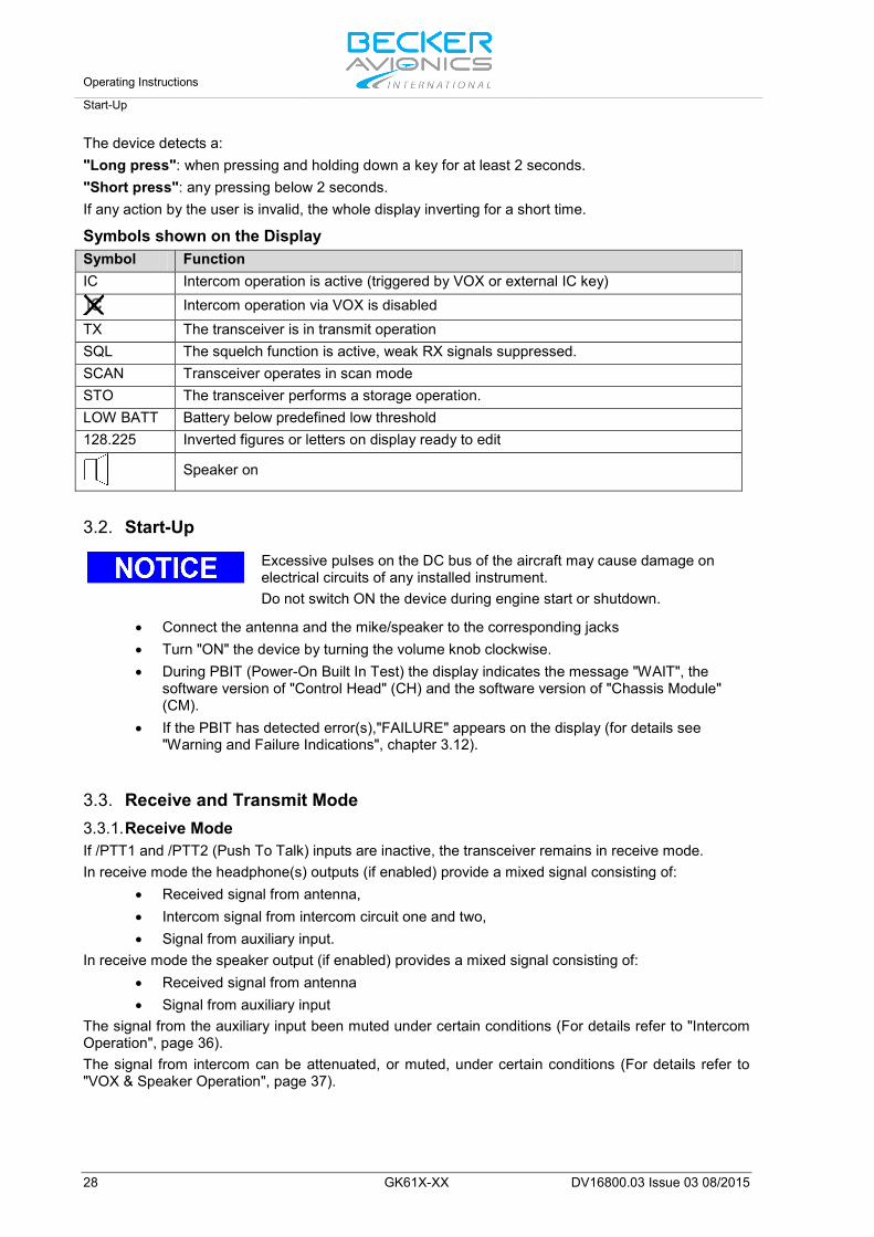
Symbols shown on the Display Symbol Function IC Intercom operation is active (triggered by VOX or external IC key)
Intercom operation via VOX is disabled TX The transceiver is in transmit operation SQL The squelch function is active, weak RX signals suppressed. SCAN Transceiver operates in scan mode STO The transceiver performs a storage operation. LOW BATT Battery below predefined low threshold 128.225 Inverted figures or letters on display ready to edit
Speaker on
3.2. Start-Up
Excessive pulses on the DC bus of the aircraft may cause damage on electrical circuits of any installed instrument. Do not switch ON the device during engine start or shutdown.
• Connect the antenna and the mike/speaker to the corresponding jacks • Turn "ON" the device by turning the volume knob clockwise. • During PBIT (Power-On Built In Test) the display indicates the message "WAIT", the
software version of "Control Head" (CH) and the software version of "Chassis Module" (CM).
• If the PBIT has detected error(s),"FAILURE" appears on the display (for details see "Warning and Failure Indications", chapter 3.12).
3.3. Receive and Transmit Mode 3.3.1. Receive Mode If /PTT1 and /PTT2 (Push To Talk) inputs are inactive, the transceiver remains in receive mode. In receive mode the headphone(s) outputs (if enabled) provide a mixed signal consisting of:
• Received signal from antenna, • Intercom signal from intercom circuit one and two, • Signal from auxiliary input.
In receive mode the speaker output (if enabled) provides a mixed signal consisting of: • Received signal from antenna • Signal from auxiliary input
The signal from the auxiliary input been muted under certain conditions (For details refer to "Intercom Operation", page 36). The signal from intercom can be attenuated, or muted, under certain conditions (For details refer to "VOX & Speaker Operation", page 37).
Operating Instructions
Frequency Selection Modes
DV16800.03 Issue 03 08/2015 GK61X-XX 29
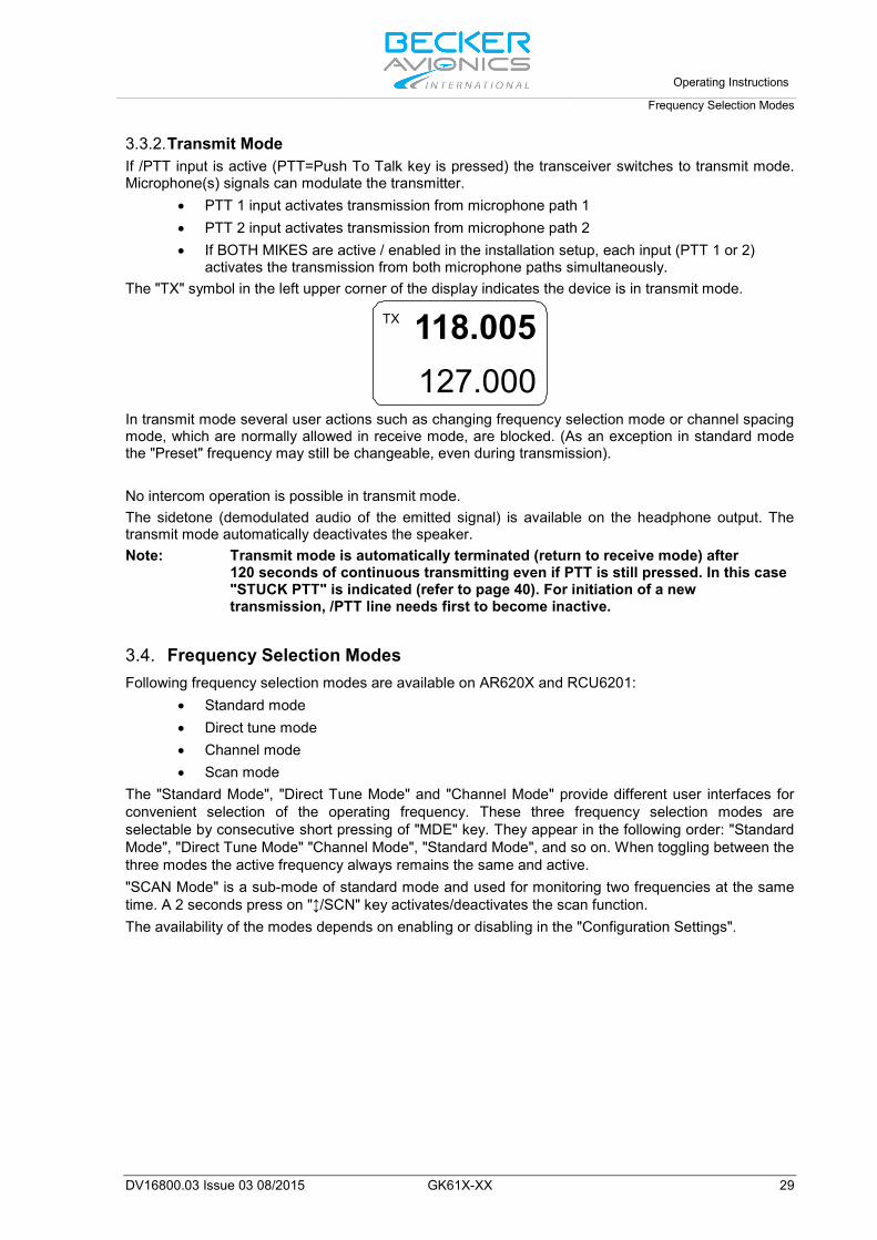
3.3.2. Transmit Mode If /PTT input is active (PTT=Push To Talk key is pressed) the transceiver switches to transmit mode. Microphone(s) signals can modulate the transmitter.
• PTT 1 input activates transmission from microphone path 1 • PTT 2 input activates transmission from microphone path 2 • If BOTH MIKES are active / enabled in the installation setup, each input (PTT 1 or 2)
activates the transmission from both microphone paths simultaneously. The "TX" symbol in the left upper corner of the display indicates the device is in transmit mode.
118.005127.000
TX
In transmit mode several user actions such as changing frequency selection mode or channel spacing mode, which are normally allowed in receive mode, are blocked. (As an exception in standard mode the "Preset" frequency may still be changeable, even during transmission). No intercom operation is possible in transmit mode. The sidetone (demodulated audio of the emitted signal) is available on the headphone output. The transmit mode automatically deactivates the speaker. Note: Transmit mode is automatically terminated (return to receive mode) after
120 seconds of continuous transmitting even if PTT is still pressed. In this case "STUCK PTT" is indicated (refer to page 40). For initiation of a new transmission, /PTT line needs first to become inactive.
3.4. Frequency Selection Modes Following frequency selection modes are available on AR620X and RCU6201:
• Standard mode • Direct tune mode • Channel mode • Scan mode
The "Standard Mode", "Direct Tune Mode" and "Channel Mode" provide different user interfaces for convenient selection of the operating frequency. These three frequency selection modes are selectable by consecutive short pressing of "MDE" key. They appear in the following order: "Standard Mode", "Direct Tune Mode" "Channel Mode", "Standard Mode", and so on. When toggling between the three modes the active frequency always remains the same and active. "SCAN Mode" is a sub-mode of standard mode and used for monitoring two frequencies at the same time. A 2 seconds press on "↕/SCN" key activates/deactivates the scan function. The availability of the modes depends on enabling or disabling in the "Configuration Settings".
Operating Instructions Frequency Selection Modes
30 GK61X-XX DV16800.03 Issue 03 08/2015
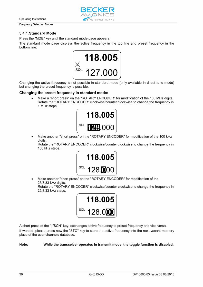
3.4.1. Standard Mode Press the "MDE" key until the standard mode page appears. The standard mode page displays the active frequency in the top line and preset frequency in the bottom line.
118.005127.000
ICSQL
Changing the active frequency is not possible in standard mode (only available in direct tune mode) but changing the preset frequency is possible.
Changing the preset frequency in standard mode: • Make a "short press" on the "ROTARY ENCODER" for modification of the 100 MHz digits.
Rotate the "ROTARY ENCODER" clockwise/counter clockwise to change the frequency in 1 MHz steps.
118.005128.000SQL
• Make another "short press" on the "ROTARY ENCODER" for modification of the 100 kHz
digits. Rotate the "ROTARY ENCODER" clockwise/counter clockwise to change the frequency in 100 kHz steps.
118.005128.000SQL
• Make another "short press" on the "ROTARY ENCODER" for modification of the
25/8.33 kHz digits. Rotate the "ROTARY ENCODER" clockwise/counter clockwise to change the frequency in 25/8.33 kHz steps.
128.000SQL
118.005
A short press of the "↨/SCN" key, exchanges active frequency to preset frequency and vice versa. If wanted, please press now the "STO" key to store the active frequency into the next vacant memory place of the user channels database. Note: While the transceiver operates in transmit mode, the toggle function is disabled.
Operating Instructions
Frequency Selection Modes
DV16800.03 Issue 03 08/2015 GK61X-XX 31
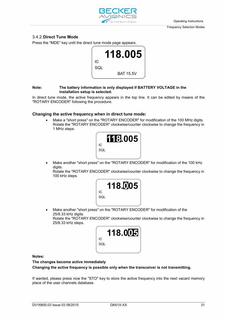
3.4.2. Direct Tune Mode Press the "MDE" key until the direct tune mode page appears.
ICSQL
118.005BAT 15.5V
Note: The battery information is only displayed if BATTERY VOLTAGE in the
installation setup is selected. In direct tune mode, the active frequency appears in the top line. It can be edited by means of the "ROTARY ENCODER" following the procedure.
Changing the active frequency when in direct tune mode: • Make a "short press" on the "ROTARY ENCODER" for modification of the 100 MHz digits.
Rotate the "ROTARY ENCODER" clockwise/counter clockwise to change the frequency in 1 MHz steps.
ICSQL
118.005
• Make another "short press" on the "ROTARY ENCODER" for modification of the 100 kHz
digits. Rotate the "ROTARY ENCODER" clockwise/counter clockwise to change the frequency in 100 kHz steps.
ICSQL
118.005
• Make another "short press" on the "ROTARY ENCODER" for modification of the
25/8.33 kHz digits. Rotate the "ROTARY ENCODER" clockwise/counter clockwise to change the frequency in 25/8.33 kHz steps.
ICSQL
118.005
Notes: The changes become active immediately Changing the active frequency is possible only when the transceiver is not transmitting. If wanted, please press now the "STO" key to store the active frequency into the next vacant memory place of the user channels database.

Operating Instructions Frequency Selection Modes
32 GK61X-XX DV16800.03 Issue 03 08/2015
3.4.3. Channel Mode The channel mode shows data from User Channels Database (indicated by "CH"), or Last Channels Database (indicated by "LAST") and shows if applied a customized label (identifier) for the frequency (max. 10 characters). The channel database provides storage of:
• CH01 to CH99 and • LAST 1 to LAST 9.
Note The functions "LAST" and Store/Restore are only available if this options are activated in "Configuration Settings" - "MEM OPTIONS".
Note: If the device is operating in the 25 kHz mode a selection of an earlier stored 8.33 kHz channel is not possible. For selection of 8.33 kHz channels, the device must operate in 8.33 + 25 kHz mixed mode.
Press the "MDE" key the channel mode page appears. By means of channel number stored frequencies can be selected. The top line shows the corresponding frequency and the bottom line the customized label (identifier) assigned to the frequency number. If the active frequency has no assigned channel number the indication is "CH--".
ICSQL
125.875CH
TWR EDSB 01
ICSQL
125.875LAST
TWR EDSB 1
3.4.3.1. Select Channels: Example: With CH01 user channel shown on display: In order to select the channel number:
• The first turn clockwise in channel mode provides navigation up user channels CH01 to CH99.
o Make a short press of the "ROTARY ENCODER", or: o Make one clockwise turn of the "ROTARY ENCODER".
The channel number is now highlighted and the channel can be changed turning the "ROTARY ENCODER". At each step the receiver tunes immediately to the displayed frequency.
• The first turn counter-clockwise will enter to the channel "LAST 1. o The channel number is now highlighted and one of the nine last used channels is
selectable by turning the "ROTARY ENCODER" either counter clockwise or clockwise.
The "LAST" mode is left automatically after a 5 second timeout or can be deselected by repeated pressing of the "ROTARY ENCODER". When leaving the "LAST" channel database and the last shown frequency is not stored in the User channel database, "CH__" appear on the display. Press "STO" to start the storage process.
Leave Channel Mode: Press the "MDE" key the standard page appears.
Operating Instructions
Frequency Selection Modes
DV16800.03 Issue 03 08/2015 GK61X-XX 33
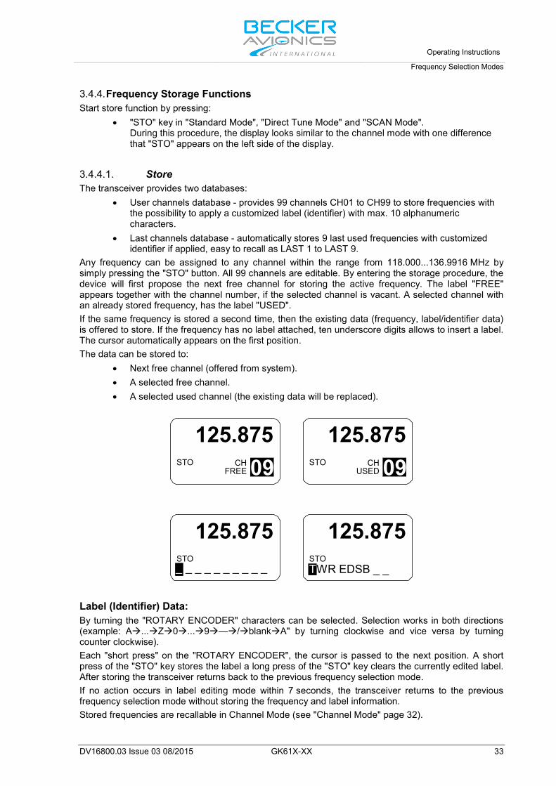
3.4.4. Frequency Storage Functions Start store function by pressing:
• "STO" key in "Standard Mode", "Direct Tune Mode" and "SCAN Mode". During this procedure, the display looks similar to the channel mode with one difference that "STO" appears on the left side of the display.
3.4.4.1. Store The transceiver provides two databases:
• User channels database - provides 99 channels CH01 to CH99 to store frequencies with the possibility to apply a customized label (identifier) with max. 10 alphanumeric characters.
• Last channels database - automatically stores 9 last used frequencies with customized identifier if applied, easy to recall as LAST 1 to LAST 9.
Any frequency can be assigned to any channel within the range from 118.000...136.9916 MHz by simply pressing the "STO" button. All 99 channels are editable. By entering the storage procedure, the device will first propose the next free channel for storing the active frequency. The label "FREE" appears together with the channel number, if the selected channel is vacant. A selected channel with an already stored frequency, has the label "USED". If the same frequency is stored a second time, then the existing data (frequency, label/identifier data) is offered to store. If the frequency has no label attached, ten underscore digits allows to insert a label. The cursor automatically appears on the first position. The data can be stored to:
• Next free channel (offered from system). • A selected free channel. • A selected used channel (the existing data will be replaced).
STO CHFREE 09
125.875
STO 09CHUSED
125.875
STO_ _ _ _ _ _ _ _ _ _
125.875
STOTWR EDSB _ _
125.875
Label (Identifier) Data: By turning the "ROTARY ENCODER" characters can be selected. Selection works in both directions (example: A...Z0...9—/blankA" by turning clockwise and vice versa by turning counter clockwise). Each "short press" on the "ROTARY ENCODER", the cursor is passed to the next position. A short press of the "STO" key stores the label a long press of the "STO" key clears the currently edited label. After storing the transceiver returns back to the previous frequency selection mode. If no action occurs in label editing mode within 7 seconds, the transceiver returns to the previous frequency selection mode without storing the frequency and label information. Stored frequencies are recallable in Channel Mode (see "Channel Mode" page 32).
Operating Instructions Frequency Selection Modes
34 GK61X-XX DV16800.03 Issue 03 08/2015
3.4.5. Automatic Storage Function The transceiver stores 9 recently selected frequencies and updates the last channels database during operation in "Standard Mode", "Direct Tune Mode" and "Scan Mode". When changing to a new active frequency, the previous active frequency is stored "LAST" in memory LAST 1. The frequencies previously located in LAST 1…LAST 8 are shifted to memory channels LAST 2…LAST 9. This algorithm ensures the last 9 used active frequencies are available. Last used frequencies "LAST" can be recalled in channel mode (see "Channel Mode" page 32). Note The functions "LAST" and Store/Restore to channels are only available if this options are activated in "Configuration Settings" - "MEM OPTIONS".
3.4.5.1. Delete data: The stored content in User Channel Database can only be deleted in "Configuration Settings". Please note the whole channel database will be reset.
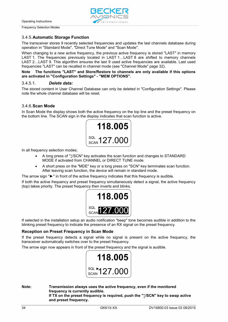
3.4.6. Scan Mode In Scan Mode the display shows both the active frequency on the top line and the preset frequency on the bottom line. The SCAN sign in the display indicates that scan function is active.
118.005127.000SQL
SCAN
In all frequency selection modes; • A long press of "↕/SCN" key activates the scan function and changes to STANDARD
MODE if activated from CHANNEL or DIRECT TUNE mode. • A short press on the "MDE" key or a long press on "SCN" key terminates scan function.
After leaving scan function, the device will remain in standard mode. The arrow sign "►" in front of the active frequency indicates that this frequency is audible. If both the active frequency and preset frequency simultaneously detect a signal, the active frequency (top) takes priority. The preset frequency then inverts and blinks.
127.000118.005
SQLSCAN
If selected in the installation setup an audio notification "beep" tone becomes audible in addition to the blinking preset frequency to indicate the presence of an RX signal on the preset frequency.
Reception on Preset Frequency in Scan Mode If the preset frequency detects a signal while no signal is present on the active frequency, the transceiver automatically switches over to the preset frequency. The arrow sign now appears in front of the preset frequency and the signal is audible.
127.000118.005
SQLSCAN
Note: Transmission always uses the active frequency, even if the monitored
frequency is currently audible. If TX on the preset frequency is required, push the "↨/SCN" key to swap active and preset frequency.
Operating Instructions
SQUELCH
DV16800.03 Issue 03 08/2015 GK61X-XX 35
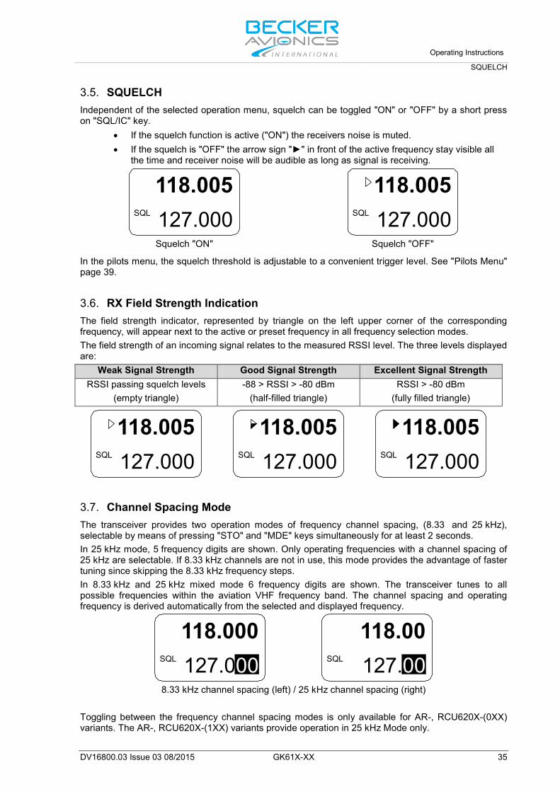
3.5. SQUELCH Independent of the selected operation menu, squelch can be toggled "ON" or "OFF" by a short press on "SQL/IC" key.
• If the squelch function is active ("ON") the receivers noise is muted. • If the squelch is "OFF" the arrow sign "►" in front of the active frequency stay visible all
the time and receiver noise will be audible as long as signal is receiving.
127.000118.005
SQL
127.000118.005
SQL
Squelch "ON" Squelch "OFF"
In the pilots menu, the squelch threshold is adjustable to a convenient trigger level. See "Pilots Menu" page 39.
3.6. RX Field Strength Indication The field strength indicator, represented by triangle on the left upper corner of the corresponding frequency, will appear next to the active or preset frequency in all frequency selection modes. The field strength of an incoming signal relates to the measured RSSI level. The three levels displayed are:
Weak Signal Strength Good Signal Strength Excellent Signal Strength RSSI passing squelch levels
(empty triangle) -88 > RSSI > -80 dBm
(half-filled triangle) RSSI > -80 dBm
(fully filled triangle)
127.000118.005
SQL
127.000118.005
SQL
127.000118.005
SQL
3.7. Channel Spacing Mode The transceiver provides two operation modes of frequency channel spacing, (8.33 and 25 kHz), selectable by means of pressing "STO" and "MDE" keys simultaneously for at least 2 seconds. In 25 kHz mode, 5 frequency digits are shown. Only operating frequencies with a channel spacing of 25 kHz are selectable. If 8.33 kHz channels are not in use, this mode provides the advantage of faster tuning since skipping the 8.33 kHz frequency steps. In 8.33 kHz and 25 kHz mixed mode 6 frequency digits are shown. The transceiver tunes to all possible frequencies within the aviation VHF frequency band. The channel spacing and operating frequency is derived automatically from the selected and displayed frequency.
127.000118.000
SQL
127.00118.00
SQL
8.33 kHz channel spacing (left) / 25 kHz channel spacing (right)
Toggling between the frequency channel spacing modes is only available for AR-, RCU620X-(0XX) variants. The AR-, RCU620X-(1XX) variants provide operation in 25 kHz Mode only.
Operating Instructions Auxiliary Audio Input
36 GK61X-XX DV16800.03 Issue 03 08/2015
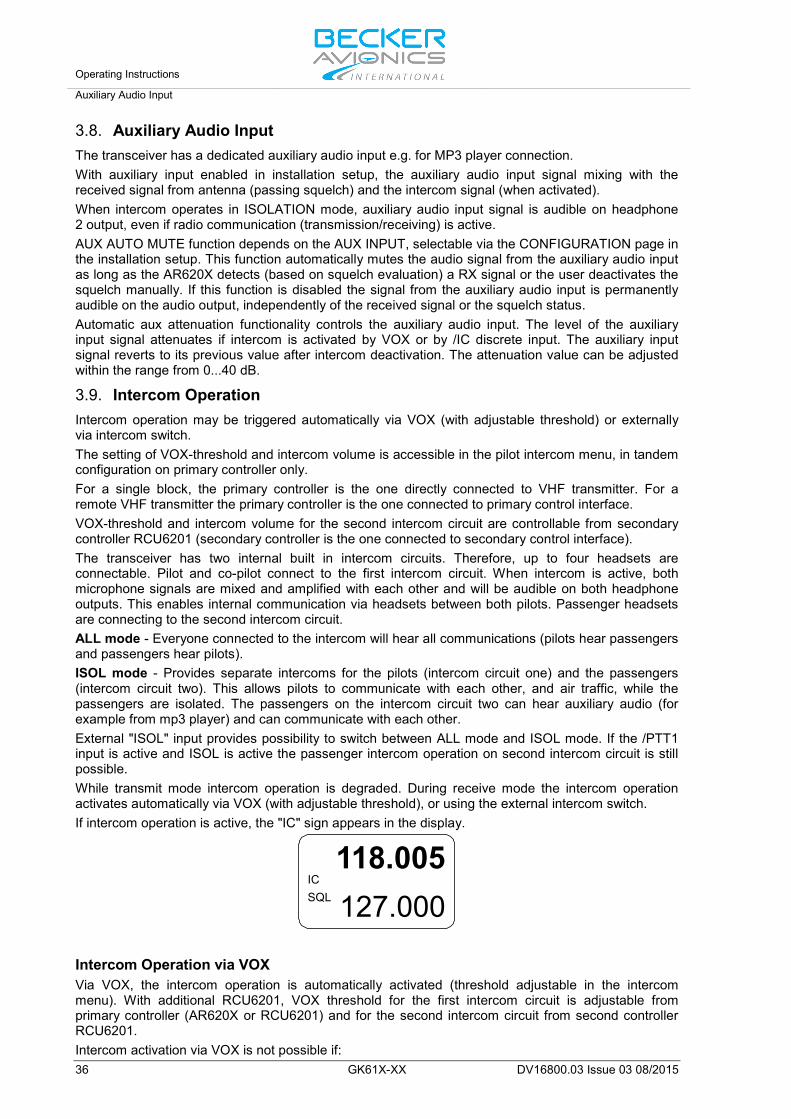
3.8. Auxiliary Audio Input The transceiver has a dedicated auxiliary audio input e.g. for MP3 player connection. With auxiliary input enabled in installation setup, the auxiliary audio input signal mixing with the received signal from antenna (passing squelch) and the intercom signal (when activated). When intercom operates in ISOLATION mode, auxiliary audio input signal is audible on headphone 2 output, even if radio communication (transmission/receiving) is active. AUX AUTO MUTE function depends on the AUX INPUT, selectable via the CONFIGURATION page in the installation setup. This function automatically mutes the audio signal from the auxiliary audio input as long as the AR620X detects (based on squelch evaluation) a RX signal or the user deactivates the squelch manually. If this function is disabled the signal from the auxiliary audio input is permanently audible on the audio output, independently of the received signal or the squelch status. Automatic aux attenuation functionality controls the auxiliary audio input. The level of the auxiliary input signal attenuates if intercom is activated by VOX or by /IC discrete input. The auxiliary input signal reverts to its previous value after intercom deactivation. The attenuation value can be adjusted within the range from 0...40 dB.
3.9. Intercom Operation Intercom operation may be triggered automatically via VOX (with adjustable threshold) or externally via intercom switch. The setting of VOX-threshold and intercom volume is accessible in the pilot intercom menu, in tandem configuration on primary controller only. For a single block, the primary controller is the one directly connected to VHF transmitter. For a remote VHF transmitter the primary controller is the one connected to primary control interface. VOX-threshold and intercom volume for the second intercom circuit are controllable from secondary controller RCU6201 (secondary controller is the one connected to secondary control interface). The transceiver has two internal built in intercom circuits. Therefore, up to four headsets are connectable. Pilot and co-pilot connect to the first intercom circuit. When intercom is active, both microphone signals are mixed and amplified with each other and will be audible on both headphone outputs. This enables internal communication via headsets between both pilots. Passenger headsets are connecting to the second intercom circuit. ALL mode - Everyone connected to the intercom will hear all communications (pilots hear passengers and passengers hear pilots). ISOL mode - Provides separate intercoms for the pilots (intercom circuit one) and the passengers (intercom circuit two). This allows pilots to communicate with each other, and air traffic, while the passengers are isolated. The passengers on the intercom circuit two can hear auxiliary audio (for example from mp3 player) and can communicate with each other. External "ISOL" input provides possibility to switch between ALL mode and ISOL mode. If the /PTT1 input is active and ISOL is active the passenger intercom operation on second intercom circuit is still possible. While transmit mode intercom operation is degraded. During receive mode the intercom operation activates automatically via VOX (with adjustable threshold), or using the external intercom switch. If intercom operation is active, the "IC" sign appears in the display.
118.005127.000
ICSQL
Intercom Operation via VOX Via VOX, the intercom operation is automatically activated (threshold adjustable in the intercom menu). With additional RCU6201, VOX threshold for the first intercom circuit is adjustable from primary controller (AR620X or RCU6201) and for the second intercom circuit from second controller RCU6201. Intercom activation via VOX is not possible if:

Operating Instructions
VOX & Speaker Operation
DV16800.03 Issue 03 08/2015 GK61X-XX 37
• It is enabled • User switched the VOX off
In both cases, VOX is disabled and the display shows the sign to indicate that activation via VOX is not possible.
118.005127.000
ICSQL
Intercom Operation via Intercom Switch Via intercom switch (pin P1-7) independent of VOX or speaker status (enabled/disabled) the intercom operation can be activated externally. The external intercom switch has priority. During intercom operation the speaker output is disabled.
3.10. VOX & Speaker Operation Depending on wiring and installation setup, the speaker may either always been enabled, or the speaker can be enabled/disabled by switching configurations using external switch /MIKE_SW.
When speaker enabled and not muted, the display will show the loudspeaker sign.
118.005127.000
ICSQL
With active enabled speaker in audio configuration, VOX always forced "OFF" and intercom via VOX is not possible (to avoid oscillation of VOX due to acoustical feedback). In transmission mode the speaker output is muted (switched "OFF") even if speaker is enabled in current audio configuration in one of the following cases:
• Intercom is activated by external intercom switch (I/C input). • Power is below 10 V.
3.11. Menus During normal operation in one of the frequency selection modes, the following menus are available:
• The Intercom menu allows adjustment of intercom volume and VOX threshold. • The Pilots menu allows adjustment of panel brightness and squelch threshold.
3.11.1. Intercom Menu A long press (2 s) on "IC/SQL" key activates the intercom menu.The page intercom volume appears. In this menu a short press on "IC/SQL" key provides toggling between the pages. The intercom menu consists of two pages:
• IC VOLUME, • IC VOX.
A long press on "MDE" key terminates intercom menu, otherwise the menu automatically terminates after 5 seconds timeout.
Operating Instructions Menus
38 GK61X-XX DV16800.03 Issue 03 08/2015
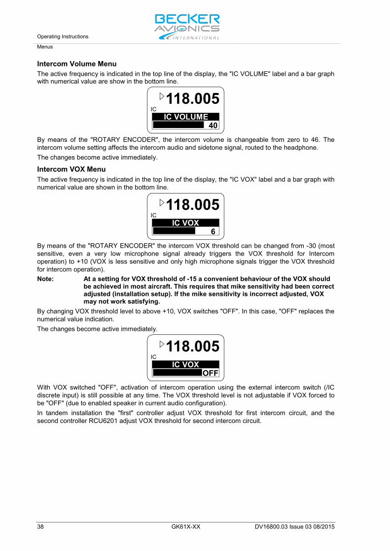
Intercom Volume Menu The active frequency is indicated in the top line of the display, the "IC VOLUME" label and a bar graph with numerical value are show in the bottom line.
IC VOLUME40
IC118.005
By means of the "ROTARY ENCODER", the intercom volume is changeable from zero to 46. The intercom volume setting affects the intercom audio and sidetone signal, routed to the headphone. The changes become active immediately.
Intercom VOX Menu The active frequency is indicated in the top line of the display, the "IC VOX" label and a bar graph with numerical value are shown in the bottom line.
IC VOX 6
IC118.005
By means of the "ROTARY ENCODER" the intercom VOX threshold can be changed from -30 (most sensitive, even a very low microphone signal already triggers the VOX threshold for Intercom operation) to +10 (VOX is less sensitive and only high microphone signals trigger the VOX threshold for intercom operation). Note: At a setting for VOX threshold of -15 a convenient behaviour of the VOX should
be achieved in most aircraft. This requires that mike sensitivity had been correct adjusted (installation setup). If the mike sensitivity is incorrect adjusted, VOX may not work satisfying.
By changing VOX threshold level to above +10, VOX switches "OFF". In this case, "OFF" replaces the numerical value indication. The changes become active immediately.
IC VOXOFF
IC118.005
With VOX switched "OFF", activation of intercom operation using the external intercom switch (/IC discrete input) is still possible at any time. The VOX threshold level is not adjustable if VOX forced to be "OFF" (due to enabled speaker in current audio configuration). In tandem installation the "first" controller adjust VOX threshold for first intercom circuit, and the second controller RCU6201 adjust VOX threshold for second intercom circuit.

Operating Instructions
Menus
DV16800.03 Issue 03 08/2015 GK61X-XX 39
3.11.2. Pilots Menu Press the "MDE" key for 2 seconds to start the pilots menu. Toggling between the pages by a short press of the "MDE" key, or by a short press of the "ROTARY ENCODER". The pilots menu consists of two pages:
• BRIGHTNESS • SQUELCH TRH
To exit the pilots menu either • Wait 5 seconds without any switch selections. • Press the "MDE" key again for 2 second, • Press the "ROTARY ENCODER" when the SQUELCH setting page is visible,
BRIGHTNESS The active frequency appears in the top line of the display "BRIGHTNESS" label appears in combination with a bar graph and the selected value.
BRIGHTNESS96
IC118.005
The panel brightness for display illumination and push buttons can be changed from 0 (illumination off) to 100 (maximum brightness) by turning the "ROTARY ENCODER". Note: This page is not available if in installation setup the dimming input is set to 14 V
or 28 V. For this setting, the aircraft dimming circuit controls the brightness parameters.
SQUELCH A short press on the "ROTARY ENCODER" provides "SQUELCH" trigger level adjustment. The active frequency appears in the top line of the display. On the bottom line "SQUELCH" with bar graph and value is indicated.
SQUELCH10
IC118.005
By means of the "ROTARY ENCODER", the squelch threshold is adjustable:
• At a setting to 6 (very weak signals are audible with high noise content; squelch opens at about -105 dBm).
• At a setting to 26 (only quite strong signals are audible with low noise content; squelch opens at about -87 dBm). With this adjustment the receiver sensitivity is significant reduced.

Operating Instructions Warning and Failure Indications
40 GK61X-XX DV16800.03 Issue 03 08/2015
3.12. Warning and Failure Indications Display Contents Description
LOW BATTERYIC
118.005
Appear in 3-second cycle
"LOW BATT" is indicated if the supply voltage of the transceiver is below the threshold defined in the installation setup. The transceiver is still operable but may have a reduced performance depending on supply voltage. Possible reasons for indication: Accumulator capacity problems (gliders), Power interrupts, General power supply problems, Setting for low battery threshold too high
STUCK PTTIC
118.005
Appear in 3-second cycle
"STUCK PTT" is indicated after 120 seconds of continued transmission. The transceiver goes back to receive mode even if the PTT line is still active (GND). For initiating a new transmission, the PTT line needs first to become inactive (open). Possible reasons for indication: Transmission lasts more than 120 seconds. PTT-key is stuck. PTT line permanently grounded (short circuit in installation).
TX HOTIC
118.005
Appear in 3-second cycle
"TX HOT" is indicated if the internal device temperature exceeds +90 °C. Transceiver is still operable. Performance of transmitter is reduced. Possible reasons for indication: Very hot environmental temperature, long transmissions times and insufficient airflow conditions.
FAILUREIC
118.005
Appear in 3-second cycle
The transceiver has detected an internal failure during normal operation. Depending on failure reason, the device may still be operable with degraded performance, or not operable at all. Possible reasons for indication: Specified environmental conditions HW or SW failure inside the transceiver. Contact maintenance shop for assistance.
FAILUREPRESS ANY KEY
The transceiver has detected an internal failure during start up. Depending on failure reason, the device may be still operable with degraded performance or not operable at all. Possible reasons for indication: Outside specified environmental conditions HW or SW failure inside the transceiver. Contact maintenance shop for assistance.
FAILURE
The transceiver has no communication with the controller. Depending on failure reason, the device may be still operable with degraded performance or not operable at all. Possible reasons for indication: Problem with inter-wiring Contact maintenance shop for assistance.

Operating Instructions
Warning and Failure Indications
DV16800.03 Issue 03 08/2015 GK61X-XX 41
In case of additional questions contact your local BECKER dealer or forward your request direct to BECKER "Product Support Department”. In the event of damage or a defect, the entire device must be returned for repair. The repair must be made by trained BECKER personnel.
Becker Avionics GmbH • Baden-Airpark B108 • 77836 Rheinmünster • Germany
+49 (0) 7229 / 305-0 • Fax +49 (0) 7229 / 305-217
Customer Service:
Sales Email: [email protected]
Support in German or English
Email: [email protected]
Support in French E-Mail: [email protected]
User Conversions and Changes are Not Permitted Any change made by the user excludes any liability on our part (excluding updates for the navigation data base and excluding the work described in this manual).

Operating Instructions Warning and Failure Indications
42 GK61X-XX DV16800.03 Issue 03 08/2015
Blank Page
Certifications
DV16800.03 Issue 03 08/2015 GK61X-XX 43
4. Certifications In this chapter you can read about: 4.1. BAF Approval - GT6201 .............................................................................................................. 44 4.2. EC Declaration of Conformity – GT6201-05 ............................................................................... 46 4.3. EC Declaration of Conformity – GT6201-10 ............................................................................... 48 4.4. European Technical Standard Order (ETSO) Authorisation ....................................................... 50

Certifications
44 GK61X-XX DV16800.03 Issue 03 08/2015
4.1. BAF Approval - GT6201

Certifications
DV16800.03 Issue 03 08/2015 GK61X-XX 45

Certifications
46 GK61X-XX DV16800.03 Issue 03 08/2015
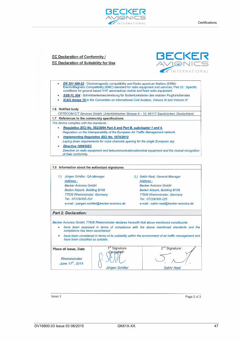
4.2. EC Declaration of Conformity – GT6201-05
Certifications
DV16800.03 Issue 03 08/2015 GK61X-XX 47

Certifications
48 GK61X-XX DV16800.03 Issue 03 08/2015
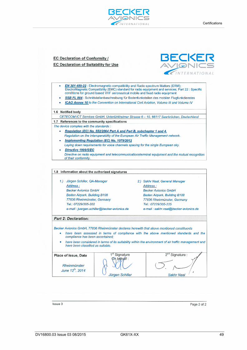
4.3. EC Declaration of Conformity – GT6201-10
Certifications
DV16800.03 Issue 03 08/2015 GK61X-XX 49

Certifications
50 GK61X-XX DV16800.03 Issue 03 08/2015
4.4. European Technical Standard Order (ETSO) Authorisation

Certifications
DV16800.03 Issue 03 08/2015 GK61X-XX 51

Index
52 GK61X-XX DV16800.03 Issue 03 08/2015
5. Index Abbreviations .................................................. 5 Activation of Intercom Operation via Intercom
Switch ....................................................... 37 Activation of Intercom Operation via VOX .... 36 Additional Conditions of Utilization ................. 7 Additional Required Equipment .................... 18 ALL Mode ..................................................... 36 Automatic Storage Function ......................... 34 Auxiliary Audio Input ..................................... 36 BRIGHTNESS .............................................. 39 Channel Mode .............................................. 32 Conditions of Utilization .................................. 7 Controls and Indications ............................... 26 Device Assignment ................................. 18, 26 Dimensions ................................................... 21 Direct Tune Mode ......................................... 31 First Issue and Changes ................................. 3 Frequency Selection Modes ......................... 29 General Description ........................................ 9 Installation ..................................................... 17 Intercom Menu .............................................. 37 Intercom Operation ....................................... 36 Intercom Volume Menu................................. 38 Intercom VOX Menu ..................................... 38 ISOL Mode .................................................... 36 List of Abbreviations ....................................... 5 Menus ........................................................... 37 Mounting ....................................................... 20
Non Warranty Clause ...................................... 7 Operation Instructions ................................... 25 Packaging, transport, storage ....................... 17 Pilots Menu ................................................... 39 Purpose of Equipment .................................. 10 Receive and Transmit Mode ......................... 28 Receive Mode ............................................... 28 Reception on Preset Frequency in Scan Mode
.................................................................. 34 RX Field Strength Indication ......................... 35 Safety Definitions ............................................ 6 Sales ............................................................. 41 Scan Mode .................................................... 34 Self-discharging ............................................ 17 Spare Parts ................................................... 15 Squelch ......................................................... 35 SQUELCH ..................................................... 39 Standard Mode.............................................. 30 Storage .......................................................... 17 Support .......................................................... 41 Support in French.......................................... 41 Transmit Mode .............................................. 29 Type Plate ..................................................... 19 Units ................................................................ 5 Variants Overview ......................................... 10 VOX & Speaker Operation ............................ 37 Warning and Failure Indications ................... 40 Warranty Conditions ....................................... 7
We reserve the right to make technical changes. The data correspond to the current status at the time of printing.
*** End of the Document ***