Embed Size (px)
Citation preview
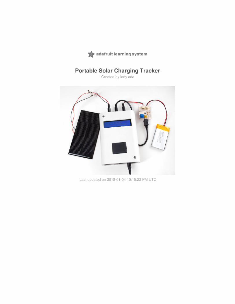
Portable Solar Charging TrackerCreated by lady ada
Last updated on 2018-01-04 10:15:23 PM UTC
233
569
11161824
Guide Contents
Guide ContentsIntroduction
Portable solar charging tracker
Parts ListAnalog StuffCasingLCDLCD Connect and TestMechanicalFinishing
© Adafruit Industries https://learn.adafruit.com/portable-solar-charging-tracker Page 2 of 26

Introduction
Portable solar charging tracker
This is actually not any sort of product or public project (!) - it's something I designed to help me evaluate solar panelsand how they act when charging batteries. Normally this requires a lot of multimeters and it's a bit of a pain to do if youhave to constantly change out panels. So I decided I would build a specialized tool that would assist me. Here is what Iwanted!
Portable! Its hard to test solar panels insideAbility to log to an SD card for long-term data analysis (to be added later)Keep track of the solar panel voltageKeep track of the battery voltageKeep track of how much current is going thru the panel to the charger
I figured if I had to build this, someone might find my notes useful. However, this documentation is primarly intended todemonstrate how to use the enclosure we carry in the adafruit shop.
This design is intended for ~6V panels, single Lithium Polymer cells and chargers. It can very easily be adapted to anykind of panel and charger, you'll just need to adjust the resistor dividers and such!
© Adafruit Industries https://learn.adafruit.com/portable-solar-charging-tracker Page 3 of 26

Please note, this project isn't a solar-powered datalogger. You do need to power it with batteries, it's only meant foranalysis of panels!
© Adafruit Industries https://learn.adafruit.com/portable-solar-charging-tracker Page 4 of 26

Parts ListThe Arduino, case and display:
Arduino DuemilanoveEnclosure for Arduino16x2 LCD0.1" header and potentiometer to go with the LCD, if you buy from the Adafruit shop they're includedDatalogging shield or prototyping shield (we don't actually do any datalogging in this tutorial, so if you just wantto view and not track, a protoshield will work just fine.)Premium female jumper wires (You can also just use plain wire, but we wanted to be able to detach the LCD withease.)
The analog electronics!
3 x 10K resistors1 x 47K resistor1 x 15K resistors1 x 1.0K resistor3 x 3.5mm terminal blocks0.1 ohm (current sense) resistor8-pin DIP dual rail-to-rail input/output opamp (TS922 works well)8-pin DIP socket for opamp3 x mono 3.5mm phono jacks3 x mono 3.5mm phono plugs
Then of course, the stuff to log. You can subsitute other types of batteries & chargers.
6V 1W solar panelLipoly chargerLithium poly battery
If you want to take it outside you'll need a portable power source, we like AA's but you can also use a 9V if you're notgoing to be out long.
6 x AA battery holder9V holder with switch9V battery clip
© Adafruit Industries https://learn.adafruit.com/portable-solar-charging-tracker Page 5 of 26

Analog StuffThere's a little bit of analog stuff going on. The two easiest parts to understand is the voltage dividers made of R1 & R2and R3 & R4. R1 & R2 take the 6V solar panel voltage and divide it by two (just make R1 = R2) so that the input to theanalog converter is under 3.3V. Likewise, R3 & R4 take the as-high-as 4.2V lipoly voltage and divide it by 3/5 to get itdown to under 3.3V so we can track that voltage.
The more complex part is the op amp that is used to measure the current draw. We stick a 0.1 ohm resistor betweenthe negative wire of the solar panel and ground, so that we can measure the current going though the panel bymeasuring across the resistor. 1 Amp of current gets turned into 100mV (our panel can't do much more than 300mAwhich would be 30mV). This is low enough that doesn't affect the solar panel's charging ability. However, 30mV isreally low and that's the maximum we expect from the panel. We use a non-inverting amplifer that amplifies thatvoltage to a bigger and easier to manage voltage. In particular. This amp multiplies the voltage by 1 + R6/R7 = 48x!That turns our 30mV max signal into 1.5V. The reason we don't amplify more is that I want to be able to use biggerpanels that can provide 500mA or more, so a little headroom will be handy.
In general, I used resistors I had lying around on my desk (except the 0.1 ohm, that value is important) so feel free toadjust the values.
If I were to build this project today, I'd use a proper high-side current sensor such as the INA219 which is precise, canmeasure high voltages, and is easy to use!Sadly it was not on hand when I originally designed this project
© Adafruit Industries https://learn.adafruit.com/portable-solar-charging-tracker Page 6 of 26

Now to the soldering iron! This is actually the most annoying part. If you don't need datalogging - just the LCDfeedback, you'll be happier if you solder this onto a protoshield as there's way more space. Click on the pictures forzoomed in shots. To solder, we bend over the wires and carefully solder together before clipping. It's sometimes a bittough to follow so go slow and check your work at each step.
Note that we tie ARef to 3.3v for more stable analog readings - especially when using battery-powered portableloggers!
© Adafruit Industries https://learn.adafruit.com/portable-solar-charging-tracker Page 7 of 26

© Adafruit Industries https://learn.adafruit.com/portable-solar-charging-tracker Page 8 of 26

CasingI'll start by prepping the case. For the bottom, snap in the pieces to cover the two holes.
Place the Arduino so it lines up with the mounting holes.
© Adafruit Industries https://learn.adafruit.com/portable-solar-charging-tracker Page 9 of 26

Attach! Use two screws, the third won't fit because the Arduino drill is too small.
© Adafruit Industries https://learn.adafruit.com/portable-solar-charging-tracker Page 10 of 26

LCDGet the LCD out of the packaging. You'll need some sort of 10K potentiometer. We will use some header and premiumsocket jumpers but you can skip that part and just solder direct wires.
Solder the header in, then we clip the unused data pins to avoid confusion.
© Adafruit Industries https://learn.adafruit.com/portable-solar-charging-tracker Page 11 of 26

Connect the LED backlight lines to the LCD logic power lines.
Ground the RW pin (it's not used).
© Adafruit Industries https://learn.adafruit.com/portable-solar-charging-tracker Page 12 of 26

And get rid of that pin as well as pins #1 and #2 (they are close to the mounting post so we'll connect to pins #15 and#16 instead).
Connect the 10K pot to 5V, pin 3 and ground.
© Adafruit Industries https://learn.adafruit.com/portable-solar-charging-tracker Page 13 of 26

And clip pin 3.
Now we have the used 8 pins, from left to right: ground, power, D7 thru D4, RS and EN. Connect sockets.
© Adafruit Industries https://learn.adafruit.com/portable-solar-charging-tracker Page 14 of 26

And clip the other end.
© Adafruit Industries https://learn.adafruit.com/portable-solar-charging-tracker Page 15 of 26

LCD Connect and TestStart with connecting up power, red goes to +5V and black goes to ground. Perform the tests in the LCD tutorial toverify the contrast pot works.
Connect the remaining wires as such:
EN → Digital #2RS → Digital #3D4 → Digital #4D5 → Digital #5D6 → Digital #6D7 → Digital #7
© Adafruit Industries https://learn.adafruit.com/portable-solar-charging-tracker Page 16 of 26

Then try out the LCD by uploading the sketch. You should get the LCD working even if it's not displaying anything.
© Adafruit Industries https://learn.adafruit.com/portable-solar-charging-tracker Page 17 of 26

MechanicalNow to connect the external panel and batteries and such. The terminal blocks are OK but not very elegant. Instead, Iwill use pluggable connectors. Audio connectors will work well here and I only need 2 pins (ground and signal) perconnection so mono 3.5mm headphone plugs and jacks are an inexpensive an easy-to-get solution. Be sure to getpanel-mount jacks!
Start with the JST cable that goes to the charger output (to measure the lipo). Unscrew the plug, slip thru the wire,Then solder each pin to crimpies. As a rule, you should always make 'sleeve' or 'ring' ground and 'tip' positive signal.Keeps things easy to track!
© Adafruit Industries https://learn.adafruit.com/portable-solar-charging-tracker Page 18 of 26

Crimp, making sure not to short the wires. This can be a bit challenging so use a multimeter to test!
Next, the miniB usb cable is stripped and the red and black wires pulled out. We also use some heatshrink to protectthe end of the cable.
© Adafruit Industries https://learn.adafruit.com/portable-solar-charging-tracker Page 19 of 26

Crimp
Heatshrink!
© Adafruit Industries https://learn.adafruit.com/portable-solar-charging-tracker Page 20 of 26

Next, the jacks. Connect any stranded wire to the sleeve and tip connections as shown.
We like heatshrink!
© Adafruit Industries https://learn.adafruit.com/portable-solar-charging-tracker Page 21 of 26

Connect the jacks to the terminal blocks.
Now is a good time to test, before finishing it all up! Verify you're getting reasonable voltages from the panel and lipolybattery. If you can get near a window, see if you can get the battery charging.
© Adafruit Industries https://learn.adafruit.com/portable-solar-charging-tracker Page 22 of 26

© Adafruit Industries https://learn.adafruit.com/portable-solar-charging-tracker Page 23 of 26

FinishingOf course, we want the panel mount jacks to be panel mounted. Grab the box end piece. It's made of ABS…
Which means they're very easy to drill or machine!
© Adafruit Industries https://learn.adafruit.com/portable-solar-charging-tracker Page 24 of 26

We have a label maker so we made nice little labels!
The other side gets the precut case that covers the Arduino power and programming slot.
© Adafruit Industries https://learn.adafruit.com/portable-solar-charging-tracker Page 25 of 26

Ready to go! Here I show how I can try different panels by connecing alligator chips. The lipo input is from thepassthrough connection on the charger. As the panel charges the battery I can track the voltages and current.
© Adafruit Industries Last Updated: 2018-01-04 10:15:23 PM UTC Page 26 of 26