Embed Size (px)
Citation preview

Student WorkbookMarch 2012
Portable Pumps and Water UseS-211
NFES 003028TM


Portable Pumps and Water Use S-211
Student Workbook
MARCH 2012 NFES 003028
Sponsored for National Wildfire Coordinating Group (NWCG) publication by the NWCG Operations and Workforce Development Committee. The use of trade, firm, or corporation names in this publication is for the information and convenience of the reader and does not constitute an endorsement by the NWCG of any product or service to the exclusion of others that may be suitable. Comments regarding the content of this publication should be directed to: National Interagency Fire Center, Fire Training, 3833 South Development Avenue, Boise, Idaho 83705. E-mail: [email protected] Additional copies of this publication may be ordered from National Interagency Fire Center, ATTN: Great Basin Cache Supply Office, 3833 South Development Avenue, Boise, Idaho 83705. Order publication number: NFES 003028.
0.1
Portable Pumps and Water Use, S-211
Unit 0 – Introduction
OBJECTIVES:
Upon completion of this unit, students will be able to:
1. Introduce instructors and students.
2. Discuss course logistics.
3. Present course overview.

0.2
0.3
I. INTRODUCTIONS
II. COURSE LOGISTICS
• Breaks – be prompt; return to class at scheduled times.
• Facility – location of vending machines, drinking fountains,
restrooms.
• Cell phones and pagers should be turned off
• Smoking policy.
• Message location and available telephones.
• Other local concerns.
III. COURSE OVERVIEW
A. Course Objective
Demonstrate knowledge and skills needed to design, set up, operate,
troubleshoot, and shut down portable water delivery systems.
B. Course Structure
• Unit 1 – Portable Water Delivery Systems
• Unit 2 – Equipment
• Unit 3 – Responsibilities
• Unit 4 – System Design and Hydraulics
• Unit 5 – Field Exercise
0.4
C. How Students Will Be Evaluated
Students must obtain a minimum score of 70% on the final exam to
receive a certificate of completion for the course.
The final exam consists of a written exam and an evaluation of student
participation in the field exercise.
D. Course Materials
• Student Workbook
• Incident Response Pocket Guide (IRPG)
• Fire Stream/Nozzle Discharge & Friction Loss Calculator
E. Course Evaluation Forms
Students are expected to complete a course evaluation form at the end
of the course.

1.1
Portable Pumps and Water Use, S-211
Unit 1 – Portable Water Delivery Systems
OBJECTIVES:
Upon completion of this unit, students will be able to:
1. Define the ultimate goal of a water delivery system.
2. List two reasons why portable water delivery systems are important for
wildland firefighting and prescribed burning.
3. Identify key factors to consider when designing, setting up, and operating a
portable water delivery system.

1.2

1.3
I. WATER DELIVERY SYSTEMS
Several types of water delivery systems are used in wildland firefighting.
Some examples are portable backpack pumps, lightweight portable pumps,
heavy portable pumps, floatable pumps, engines, and helicopter buckets.
The goal of all water delivery systems is to provide proper flow and pressure
(to the nozzles) to meet the tactical objectives.
This course focuses on the high-pressure portable pump delivery systems.
Systems range from a relatively simple setup (a single pump and a couple of
nozzles) to a complex operation with multiple pumps and many laterals with
different crews using them.
II. PORTABLE WATER DELIVERY SYSTEMS
A. Portable water delivery systems are used to supply water for:
• Hot spotting
• Anchor and flank
• Wet line
• Mop up
• Structure protection
• Storage and fill tank

1.4
B. Why Are Portable Water Delivery Systems Important?
• Efficient tool for getting water on the fire.
• Increase safety of the firefighter:
– Limits exposure: dry mopping versus wet mopping
– Hold an advancing line with water more efficiently than a
dry line.
– Quickly reduces heat.
• Cost effective compared to other methods such as aircraft,
tankers, and engines.
• Increase productivity of personnel, for example, allows
personnel to cover more line with water.
• Facilitates the achievement of Minimum Impact Suppression
Tactics (MIST); for example, a wet line is a less destructive
method compared to a dozer line or hand cut line.
C. Factors to Consider When Designing, Setting Up, and Operating a
Portable Water Delivery System
Several factors influence the type of portable system that is needed
and how it is set up and operated. This section discusses some of the
more important factors.
1. Tactical objectives
The fire tactic directly influences how the water delivery
system is designed, set up, and operated. Therefore, it is
important to know the tactical objectives.
What are examples of how tactical objectives impact the
delivery system?

1.5
2. Personnel resources
• Personnel involved with portable water delivery systems
include:
– The supervisor (e.g., IC, DIV) is typically
responsible for designing the water delivery
system, ordering equipment, being accountable for
equipment, and so on.
– The pump operator is responsible for properly
setting up a portable pump operation and
maintaining a constant water supply.
– The nozzle operator is responsible for mastering
the use of the nozzle and determining method to
apply water.
– Hand crews and other fire line personnel often
help set up and retrieve hose lay.
• How many pump and nozzle operators are needed? What
personnel are available? What experience do they have
working with pumps?
• Risk management concerns – such as personal protective
equipment (PPE), Lookouts, Communication, Escape
Routes, and Safety Zones (LCES), working with fuel,
close vicinity to fire.

1.6
3. Equipment resources
• What equipment is needed to set up the delivery system?
Pumps DO break down, and it pays to have a backup
pump. Sometimes troubleshooting a pump takes too long,
and it would be more efficient to simply set up another
pump.
• What equipment is available? When can it become
available?
• What is the condition of the equipment?
4. Site characteristics
• Water supply
The water supply is critical to the delivery system. If the
water source is not adequate, tactics may need to change.
– What water sources are available (e.g., creeks,
ponds, lakes, and pools)?
– Is any approval needed to use the water source, for
example, an agreement?
– Does the water source have enough water to meet
the tactical objectives? Can it provide the flow that
is need? Is the water source deep enough and clean
enough for the pump to work?
– How far is the water source from the fire or
structure?

1.7
• Terrain (e.g., steep hills, level ground)
The terrain impacts delivery system design and site setup,
for example, if the hose lay has to run up a steep hill or if
the water source is far away from to the nozzle.
• Environmental concerns (e.g., invasive species,
threatened and endangered species, water contamination)
5. Fire behavior
Examples of fire behavior factors that need to be considered
when designing and operating a portable water delivery system
include:
• Fuel characteristics
• Fire behavior
• Weather
6. Hydraulic feasibility
The delivery system has to be hydraulically feasible or water
will not be delivered to the nozzle at the proper flow and
pressure.
1.8
EXERCISE: Thirtymile Fire Incident and the Mark 3 Pump
Purpose: The primary purpose of this exercise is to emphasize the importance of
water delivery systems and keeping pumps running.
Format: Individual and large group discussion
Materials Needed:
Thirtymile Fire Incident and the Mark 3 Pump (an excerpt from the Thirtymile Fire
Investigation Report).
Full report can be found at www.fs.fed.us/t-
d/lessons/documents/Thirtymile_Reports/Thirtymile-Final-Report-2.pdf
Instructions:
1. Scan the Thirtymile Fire Incident and the Mark 3 Pump excerpt, from the
full report, on page 1.11. Focus on those sections that refer to pump(s) – the
word “pump” has been underlined in the report.
Answer these questions and be prepared to discuss:
• What was the purpose of the pumps on the Thirtymile Fire?
• Why couldn’t the crew keep the pumps running?
• What tactical changes were made when they couldn’t keep the pumps
running?
• What were the consequences of pumps not running?
2. Discuss with class the report and the answers to the questions.
End of Exercise.

1.9
III. REVIEW
Question 1: What is the ultimate goal of a water delivery system?
Question 2: Why are portable water delivery systems important for wildland
firefighting and prescribed burning?
Question 3: What are the key factors to consider when designing, setting up,
and operating a portable water delivery system?

1.10

1.11 SR 1-1
Thirtymile Fire Incident and the Mark 3 Pump
Below is an excerpt from the Thirtymile Fire Investigation Report. This excerpt
highlights specific information in the report that is relevant to the Mark 3 Pump
and excludes a significant amount of text, figures, photos, maps, and reference
numbers. The official full Thirtymile Fire Investigation Report can be found at this
website:
www.fs.fed.us/t-d/lessons/documents/Thirtymile_Reports/Thirtymile-Final-
Report-2.pdf
In Memory Of
Tom Craven
Karen FitzPatrick
Jessica Johnson
Devin Weaver
And Dedicated To Those Who Will Be Saved
Summary
On July 10, 2001, the Forest Service Northwest Regulars #6, a Type 2 fire crew,
was entrapped by wildland fire. The fire, caused by an abandoned picnic cooking
fire, was located 30 miles north of Winthrop, Washington, along the Chewuch
River. Fourteen crewmembers and two civilians were involved in the entrapment.
The civilians arrived at the entrapment site while trying to exit the area in their
truck. Fourteen shelters were deployed. One shelter contained one Forest Service
person and the two civilians. Six individuals, four of whom died, deployed
approximately 100 feet upslope from the road. The remaining people, including the
civilians, deployed on the road. After the initial deployment they relocated to the
river. The civilians’ vehicle was destroyed by fire. The Forest Service vehicle
sustained minor damage, but was drivable. Ten Forest Service personnel and the
two civilians survived the burnover.
The following is an overview of the events and actions that took place related to
the Thirtymile Fire Incident. This overview is based on interviews with over
40 individuals, and the analysis of dispatch logs, resource orders, medical records,
weather conditions, fuel conditions, training records, and equipment performance.
Additional detailed information that is relevant to the identification of causal
factors that led to this incident is presented in the appendices and in the Findings
Section of this report.

1.12 SR 1-1
Initial Actions
On Monday evening, July 9, 2001, a Canadian Lead Plane (Bird Dog 8), returning
to Canada after supporting the Libby South Fire (burning about 20 miles south of
Winthrop, Washington), reported seeing a fire near the road along the Chewuch
River about 30 miles north of Winthrop. The report, received at 9:26 p. m. , stated
that “the fire covered two hectares or five acres with two spots ahead of it.”
Within thirty minutes a three-person initial attack crew and Engine #704 were
dispatched to Action 103 (later named the Thirtymile Fire).
The Chewuch River runs down a deep “V” canyon. Although there is little
elevation change along the canyon floor, both sides of the canyon have steep
slopes (70% to 100%). The southwest to northeast orientation of the canyon is in
alignment with afternoon ridge top and up-canyon winds.
The initial attack crew arrived at the point of origin of the fire a few minutes after
11 p. m.
They estimated the fire was burning in three to eight acres of heavy brush with
flame lengths of two to four feet. They could see two spots on the eastside of the
river, one near the river and another that was burning actively close to the east
slope.
It was later determined that the fire had started as the result of an abandoned picnic
cooking fire.
The initial attack crew thought that the fire would grow and unless they could get
water on the fire their efforts would be useless. The initial attack crew boss then
requested two engines, a Mark III pump, hoses, and at least a 10-person crew. The
initial attack crew had four bladder bags, hand tools and a chainsaw.
Engine #704 arrived at the fire about 15 minutes before midnight. The initial attack
crew boss offered the Supervisor on Engine #704 the Incident Command (IC) of
the fire. The Engine Supervisor refused the IC role since he felt it was beyond what
he could handle, it was dark, and he did not know the country very well. It was his
assessment that the fire was “20 to 25 acres … with multiple snags and numerous
candles.” This revised estimate of the fire size and the view that “it will grow, hit
the slope and get larger” was passed onto the Okanogan Dispatch by the IC. It was
decided to hold at the road until the Entiat Interagency Hotshots (Entiat IHC)
showed up.
1.13 SR 1-1
At about midnight when the Okanogan Dispatch asked the IC if the fire could be
let go until the morning, he responded that the fire needed “to be taken care of
tonight because if it hits that slope it is going to the ridge top.”
The Entiat IHC was to be located and sent to the fire after working the day on
another fire near Spokane, Washington. After bedding down for approximately 30
minutes at the Liberty High School near Twisp, Washington, about 10 miles south
of Winthrop, the Entiat IHC was awakened around midnight and sent to the
Thirtymile Fire.
Around 1:00 a. m. on Tuesday, July 10th, the Entiat IHC and a pick-up truck with
two additional firefighters arrived at the scene. The pick-up truck had a Mark III
pump, wye gates, and over 1,000 feet of hose. Although the IC offered pump
support, the Entiat IHC Superintendent felt it was not necessary. As a result the
three-person initial attack crew, Engine #704, and the pick-up truck departed at
1:30 a. m. The Entiat IHC Supervisor assumed the role of IC a little after 1:00 a. m.
The Entiat IHC began lining the fire between the road and the Chewuch River.
Numerous spots were noticed on the east side of the river. The plan of attack was
to cross the river, find the spots, and line them.
The Northwest Regulars #6
During the early morning of July 10 while the Entiat IHC crew was fighting the
Thirtymile Fire, the Northwest Regulars #6 (NWR#6), a Type 2 fire crew, was
called up. The NWR #6 crew was made up of 21 individuals from two different
Ranger Districts located in central Washington State. These were:
• the recently combined Lake Wenatchee and Leavenworth Districts(referred
to as Lake Leavenworth)
• the Naches District
Eleven members of the NWR #6 crew were from Lake Leavenworth and ten were
from Naches.
The crewmembers were contacted beginning just after midnight. They were to
assemble in Leavenworth, Washington, and then drive to the Twisp Ranger Station
for their briefing. They were informed they were being assigned to support the
Libby South Fire. The majority of the crew had as little as one or two hours of
sleep before being called.

1.14 SR 1-1
When the Lake Leavenworth and Naches members of the NWR #6 crew met in
Leavenworth around 3:00 a. m. they were organized into three squads. One squad
consisted entirely of personnel from the Naches District. The other two squads
were made up of people from both ranger districts. Not all crewmembers knew the
individuals from the other district with whom they would be working.
At 7:00 a. m. , after about a three-hour drive from Leavenworth, the crew arrived at
the Twisp Ranger Station to await their briefing. The NWR #6 crew was informed
that they would not be going to the Libby South Fire. Rather, they would be
assigned to do mop up on the smaller Thirtymile Fire. Many of the rookie
crewmembers were disappointed. Pete Soderquist and Elton Thomas, the District
FMO and Forest FMO, respectively, accompanied the NWR #6 crew to the fire.
The group arrived at the fire site just after 9:00 a. m.
The Entiat IHC Actions During the Night
The Entiat IHC began their actions to line the spots around 1:30 a. m. Within
twenty minutes Marshall Brown, the IHC Superintendent, reported that they had
completed a fireline from the road to the river.
By 2:15 a. m., after containing two spots in the mostly “dog-haired” thicket, they
moved across the river. Eventually they found a crossing log to allow easy access
to the east side of the river. At that time, Okanogan Dispatch requested information
on their resource needs for the morning. The Entiat IHC Superintendent, Marshall
Brown, ordered a crew and an aircraft for the morning. He also ordered two Mark
III pumps with kits, 1,500 feet of hose, 10 wyes, 10 nozzles, and 10 reducers.
Confirmation was received three hours later at 5:26 a. m. that a Type III helicopter
(Helicopter 13N) with a bucket and long line would be dispatched for arrival at
10:00 a. m. at the North Cascade Smokejumper Base (NCSB), located about
35 miles south of the fire site.
By 5:30 a. m. there were seven spots on the east side of the river covering about
five to six acres. Two spots were estimated to be about one acre each.
The Entiat IHC took a break between about 5:30 a. m. and 6:30 a. m. to eat and
rest. After the break they continued to work on the east side of the river digging a
containment line and surrounding the spots until the NWR #6 crew relieved them.
When they returned to the east side after 6:00 a. m. they noted that the “fire
intensity had died down a lot.”
1.15 SR 1-1
Transition to NWR #6
On the morning of July 10th, nearly all personnel on the Thirtymile Fire were
suffering some effects of mental fatigue due to lack of sleep. This includes the
Entiat IHC, the NWR #6, and key District and Forest personnel. As the day
progressed, these effects would worsen, and provide one potential explanation for
loss of situational awareness, compromised vigilance and decision-making.
When the NWR #6 crew arrived at the fire at 9:04 a. m. , the NWR #6 Crew Boss
Trainer and Trainee met with the Entiat IHC Superintendent, Marshall Brown, to
review the situation. Pete Soderquist, the District FMO, and Elton Thomas, the
Forest FMO, also participated in this situation review meeting. This review
meeting lasted about 45 minutes.
At that time the Entiat IHC provided the NWR #6 with a GPS map of the hot spots
and the Entiat IHC’s containment activities.
Ellreese Daniels and Pete Kampen, the NWR #6 Crew Boss Trainer and Crew
Boss Trainee, respectively, were shown the hot spots by Kyle Cannon, the Entiat
IHC Assistant Superintendent. It was determined that the highest priority was spots
3 and 4 on the east side of the river. The tactics were to get the pumps going early
and get water on the fire, cool it down, and have the crew mop it up.
The Forest FMO estimated that although there was a lot of fire, it only covered
about three acres scattered over a five acre area with very benign fire behavior. He
and the District FMO discussed and checked on the availability of two other IHC
crews. If they were available the plan was to have them assigned to the fire to
knock it down and get it over quickly. The District FMO requested that a barricade
be placed on the road to prevent unauthorized personnel from entering the area.
Although approved by the District Ranger for the Methow Valley, the barrier was
not put up until 3:17 p. m. that afternoon.
No Spot Fire Weather Forecast was issued for the Thirtymile Fire. Pete Soderquist
provided a weather forecast based on a Spot Fire Weather Forecast for 6:00 p. m.
the previous evening (July 9) for the Libby South Fire. This Libby South Fire
forecast indicated low relative humidity, high temperatures and that the “fuel type
was a trigger for fire behavior.”
1.16 SR 1-1
The Forest FMO reminded Pete Kampen, the NWR #6 Crew Boss Trainee, to use
the Safety Briefing Card to brief the crew. Pete Kampen briefed the three squads
using the Libby South Fire forecast information on the low humidity, high
temperature, and a predicted wind event greater than 10 mph. He explained that the
tactics would involve using hose lays to bring water from the river and digging
hand lines around the hot spots. The briefing took about half an hour and was
completed about 10:30 a. m. The NWR #6 crew was informed that this was a lot of
work for them and that another 20-person crew was staged at Tonasket,
Washington. (Later in the day Air Attack found out that this crew would arrive
about 8:00 p. m. ). During the discussion with the District FMO, Pete Kampen and
Ellreese Daniels had been informed that the NWR #6 could expect support from
Helicopter 13N for bucket work. The District FMO reminded them again just prior
to departing for a Libby South Fire planning meeting.
The NWR #6 crew had eight handheld radios. When Pete Kampen attempted to
call Okanogan Dispatch he could not make contact. Ellreese Daniels, the Crew
Boss Trainer for the NWR #6, was able to contact Okanogan Dispatch using his
handheld radio. This was in contrast to the Entiat IHC situation where they had to
use their mobile radio in their truck to contact Okanogan Dispatch.
Pete Kampen and Ellreese Daniels agreed that Daniels would assume the role of
the Incident Commander(IC) on the Thirtymile Fire and handle the
communications. Kampen would manage the strategy and tactical decisions.
Requests would be passed through Daniels to Okanogan Dispatch.
At 11:00 a. m. the Entiat IHC left the fire site and drove about two miles downriver
to bed down at a campground. Twenty minutes later Pete Soderquist and Elton
Thomas departed for the Libby South Fire ICP.
After the NWR #6 crew completed the safety briefings, the pumps were set up and
the crew crossed the log to the east side of the river and began to apply water to the
fire and dig line at about 11:00 a. m.
1.17 SR 1-1
By about noon the crew experienced several equipment-related problems:
• They had difficulties keeping the two pumps running, possibly due to
improper use of pressure relief valves, and lack of experience with pumps
and hoses.
• Several hoses burst. Some felt that the hoses were old and the pump was
“picky.”
• At least four Pulaskis broke during operations on the east side of the river.
One handle split and heads came off of the handles on three apparently new
pulaskis.
The Crew Boss Trainee, Pete Kampen, decided to change tactics and dig a line to
pinch the head of the fire. Jodie Tate, who had been operating the pumps was
pulled off to dig lines. The fireline construction was difficult with a lot of roots.
Some crewmembers realized they were digging line ahead of the fire and knew it
was a “watch-out” situation.
At 12:08 p.m. Pete Kampen requested that Helicopter 13N be launched. Twenty
minutes later he requested additional crews from Okanogan Dispatch. Twenty
minutes later he requested additional crews from Okanogan Dispatch. Daniels
considered it unusual for green foliage to be burning as it was for this time of year.
Donica Watson had been posted as a lookout on the rock screen above the crew on
the east side of the river. She was responsible for taking weather observations and
relaying information to Ellreese Daniels. As the fire behavior began to intensify,
Daniels removed her from the rock screen sometime after 2:00 p.m. because of
poor access to the escape route. She was reassigned back to her squad. At this time
Air Attack became the lookout for the Thirtymile Fire.
In response to the request for additional crews, the Okanogan Dispatch had
attempted to contact the Entiat IHC. Since the Entiat IHC had not been contacted
by 1:00 p.m., Pete Kampen sent one of the NWR #6 crewmembers to wake the
Entiat IHC. The Entiat IHC Superintendent felt that the crew required more sleep
and did not wake them until around 1:30 p.m. The Entiat IHC returned to the fire
around 2:00 p.m. The NWR #6 crewmembers were working on the east side of the
river at that time. The Entiat IHC Superintendent contacted Pete Kampen to review
the situation. A little later Kampen decided to pull the NWR #6 crew back across
the river to the road. The fire had been burning through the hoses in several places
and spotting over their containment line. Pete Kampen accepted the fact that they
“had lost the fire.” At 3:00 p.m. the NWR #6 crew was pulled back to the lunch
1.18 SR 1-1
site “safety zone” on the west side of the river. There they joined the Entiat IHC
crew and ate lunch, rested, watered, and sharpened their tools.
The Air Support Actions
Several times during the morning briefing the District FMO had informed the
NWR #6 crew boss trainee and trainer that Helicopter 13N would be available for
bucket work. Around 12:00 p.m. the NWR #6 was notified by the Okanogan
Dispatch that Helicopter 13N was available 5 miles south of Winthrop at the North
Cascade Smokejumper Base (NCSB). At 12:08 Pete Kampen (through Ellreese
Daniels as his communications connection to Dispatch) requested that Helicopter
13N be launched with a bucket.
When contacted at 12:30 p.m. concerning the estimated time of arrival, the
Okanogan Dispatch indicated that the helicopter required permission to dip out of
the Chewuch River. (This area of the Chewuch River is a Research Natural Area,
and the river is a habitat for endangered fish species).
Air Attack was diverted from the Libby South Fire to the Thirtymile Fire at
12:40 p.m. About twenty minutes later Air Attack stated that there was a dip site
available down the river and another one was two miles up the canyon. Okanogan
Dispatch repeated that they could not use the helicopter until they got permission.
Permission was received at 2:00 p.m. to use the helicopter. (A detailed review of
the sequence of events related to Helicopter 13N is presented in the Management
Findings Section.)
Helicopter 13N departed for the fire at 2:38 p.m. from 8-Mile Camp which was
about 20 miles south of the fire. Helicopter 13N began making water drops on
small spots at the south edge of the fire and continued to work until having to
refuel around 4:15 to 4:30 p.m. Before refueling, the fire had spread up the east
canyon walls. After returning from refueling, the pilot of 13N noted that the fire
spread had moved back to the canyon floor with spotting on the west wall of the
canyon.
Air Attack ordered a single engine air tanker (SEAT) at 1:15 p.m. Around
1:40 p.m. Air Attack announced that the fire was getting active, growing, and
additional crews and air support were needed soon. A few minutes after 2:00 p.m.
the SEAT flew over the fire and decided the canyon was tight. Although he did not
think it would be of much help, the SEAT pilot dropped the load on a small strip of
timber. Air Attack decided to have the SEAT reload and hold.

1.19 SR 1-1
At 2:34 p.m. Air Attack requested a heavy air tanker. About a half an hour later
Tanker 62 was en route with an estimated arrival of 3:21 p.m. Also, at about
2 p.m., Ellreese Daniels ordered another tanker and a PBY. Tanker 12 was diverted
from the Libby South Fire and arrived at the fire around 3:40 p.m. It could only
make two drops before it was out of flight time. The PBY would have to stop at
Omak Lake for water while en route to the fire.
Around 3:20 p.m., Air Attack reported that the fire had reached about 50 acres in
size and was crowning and going to the ridge. Within 15 minutes the fire had
grown to 100 acres and was almost on the ridge. Air Attack then requested two
additional Type 1 or 2 tankers.
At 4:03 p.m. the First Butte Lookout reported that the Thirtymile Fire was forming
its own thunderhead. By 4:18 p.m., Lead 66 requested the heavy tankers for the
Libby South Fire. Both Air Attack and Lead 66 agreed that it looked like the
Thirtymile Fire was going strong and it was moving in an uninhabited area. “It was
not going to help throwing air tankers at it.” The tankers were diverted to the Libby
South Fire. Helicopter 13N remained over the Thirtymile Fire dropping water.
Engines #701 & #704
At 2:27 p.m. Air Attack requested two engines. Engines #701 and #704 were then
dispatched to the fire. Initially Engine #701 had been assigned to work helispot,
dust abatement, air crash rescue, and helicopter management at 8-Mile Camp
20 miles downriver from the fire. According to Harry Dunn, the Supervisor on
Engine #701, his mission from Okanogan Dispatch was to keep spots from the
west side of the road.
Engine #704 (a 4x4 pickup with a slip-on pumper) had been directed by the Duty
Officer to put a “road closed” sign approximately one mile in from the end of the
pavement on the Chewuch road. The sign was put up at 3:17 p.m. En route to
putting up the sign Engine #704 was contacted by Okanogan Dispatch and
requested to report to the Thirtymile Fire.
The Supervisor of Engine #701 informed Engine #704 and three firefighters in a
chase vehicle that their assignment was to keep the fire east of the road as per
dispatch directions. Around 3:30 p.m. both Engines #701 and #704 arrived on the
fire scene. Neither checked in with the IC nor received a tactical briefing.

1.20 SR 1-1
Engines #701 and #704 drove past the Entiat IHC and NWR #6 crews and up the
road to attack spots. Engines #701 drove almost to the end of the road and then
headed back down looking for spots. The plan was to have Engine #701 work the
north section and Engine #704 work the south section. The spots near the road
were thought to be “rather small at this time.”
Investigation – Equipment Findings
Significant Equipment Findings
In spite of the ready availability of water, relatively little water was applied to the
fire during the initial attack phase. This was largely due to operational problems
with pumps and hoses, as well as delays in availability of a Type III helicopter.
Prior to Entrapment
1. Water handling resources were made available to the Entiat IHC at about
1 a.m. on July 10th but the IHC Supervisor released the following equipment
and personnel:
• Engine #704 (slip-on pumper on a 4wd pickup) and 3-person crew
• Chase truck and 3-person crew plus 2 other people
• Mark III pump, wye gates, over 1,000 feet of hose
2. At 2:15 a.m. the Entiat IHC Superintendent requested water handling
equipment and an aircraft for morning delivery -- two Mark III pumps,
1,500 feet of 1½-inch hose, 800 feet of 1-inch hose, 10 wyes, 10 nozzles,
and 10 reducers.
3. The water handling equipment arrived with the NWR #6 crew at 9:04 a.m.,
and was put in use at around 11 a.m. when the NWR #6 began work.
1.21 SR 1-1
4. The delivery of water for NWR #6 fire suppression activities was ineffective
because of an inability to keep the pumps running continuously.
• The hose layout (e.g., arrangement, size of hoses, and pressure reducers)
was not conducive to optimal water operations, and limited the amount of
water that the crew applied to the fire
• At least three lengths of 1-inch hose were blown.
• The pumps were not in continuous operation due to mechanical and/or
operator problems.
5. The lack of a reliable and consistent water supply operation in conjunction
with escalating fire behavior led to a decision to change the tactics from
water suppression to direct hand line construction.
6. At least four pulaskis broke during operations on east side of the river. One
handle split. The heads came off of three apparently new pulaskis.
7. Aviation resources were continuously over the fire from about 1:00 p.m. and
there were no reported equipment malfunctions on any of the aircraft.
8. No vehicle problems were reported throughout the incident
9. The following aviation resources were assigned mid to late afternoon on
July 10th:
• One Type III helicopter
• One SEAT (single engine air tanker)
• Two Type I Air tankers
• One Type II Air tanker (PBY)
• One Air Attack
• One Lead plane
10. The NWR #6 crew had eight handheld radios. There were minor problems
with some handheld radios, however there was adequate communications
capability with incident personnel, assigned aircraft, and dispatch.
11. The Okanogan Forest Dispatch radio system tape recorder was not
operational; therefore there are no voice-recorded tapes for July 9th and
10th.

1.22 SR 1-1
Note: Please see full report for information on The Entrapment, The Deployment
Area, Deployment, The Rescue and Evacuation, References, Investigation
Findings, Environment Findings, Equipment Findings, People Findings,
Management Findings, Standard Fire Orders, Watch Out Situations, Epilogue, The
Investigation Team, Incident Time Line, and Appendices. These sections are not
included here; except one part of the investigation findings related to equipment is
presented.

2.1
Portable Pumps and Water Use, S-211
Unit 2 – Equipment
OBJECTIVES:
Upon completion of this unit, students will be able to:
1. Distinguish the differences between the two cycle and four cycle engines
and identify which one of these differences is most important to a pump
operator.
2. Label the parts of a commonly used portable pump.
3. Identify the purpose of a suction hose and a discharge hose.
4. Match types of wildland fire appliances and tools with their respective
purpose.
5. Identify nozzle types.
6. List one type of national portable pump kit.

2.2
2.3
I. PORTABLE WATER PUMPS
This section discusses how pumps work, types of pumps, and parts of a
pump.
A. How Pumps Work – Engine and Pump Head
Having a basic understanding of how pumps work can make or break
a pump operator; it will help a pump operator start the pump, keep it
running, and troubleshoot in the field.
A pump is made up of two parts: an engine (power source) and a
pump head.
1. Types of engines
• Two cycle engines
With a two cycle or two stroke engine, the mixed gas
(unleaded gas and oil) is ignited every time the piston
reaches the top of the cylinder, and exhaust is evacuated
when the piston reaches the bottom of the cylinder. This
completes the two cycles the piston makes.
On initial startup there is no mixed gas in the cylinder for
the spark plug to ignite.
When the operator pulls the starter cord, the piston is
engaged and draws the mixed gas from the carburetor
into the crank case to initiate the firing sequence.
While the engine is running, the piston’s upward stoke
compresses the mixed gas in the top portion of the
cylinder, preparing it to be ignited by the spark plug.
At the same time as there is compression above the
piston, a vacuum is created in the crankcase underneath
the piston. This vacuum draws the mixed gas into the
crankcase.

2.4
The two cycles include:
– Compression (ignition)
The power generated from the combustion of the
previous power stroke provides enough
momentum in the engine for the piston to rise,
covering both the intake and exhaust ports, and
compresses the mixed gas, preparing it for
combustion by the spark plug.
– Transfer (exhaust)
As the piston begins its down stroke from the force
of the combusting mixed gas, the expanding heated
exhaust escapes out through the muffler.
A valve in the crankcase prevents backflow of the
mixed gas/air mixture into the carburetor.
As the piston reaches the bottom of its cycle, the
intake port is exposed, allowing the compressed
the mixed gas/air mixture in the crankcase to travel
into the top of the cylinder.
At this point, both the exhaust port and intake port
are momentarily exposed at the same time.
This is when some mixed gas escapes out through
the exhaust port unburned.

2.5
• Four cycle engines
In a four cycle or four stroke engine, the piston has to
raise and lower twice to complete the cycle of igniting
fuel inside a cylinder; the piston makes four cycles.
– Fuel intake (down)
During the intake of fuel, the piston moves
downward, creating a vacuum and drawing fuel/air
mixture from the carburetor through the intake
valve into the cylinder.
As the piston reaches the bottom of its first stroke,
the intake valve is closed and the piston begins the
second phase of the cycle.
– Compression of fuel (up)
The momentum from the previous ignition
sequence forces the piston to rise, compressing the
fuel/air mixture in the cylinder.
As the piston reaches the top of its stroke, the
spark plug ignites, causing rapid combustion and
expansion of the fuel/air mixture thus forcing the
piston downward.
– Power generation from firing (down)
The forcing downward of the piston is described as
horse power generated for external use of the
engine to do such things as making a car move
forward or spinning the blade on a lawn mower.
A small amount of this energy is used in the form
of inertia to drive the piston upward once more.
2.6
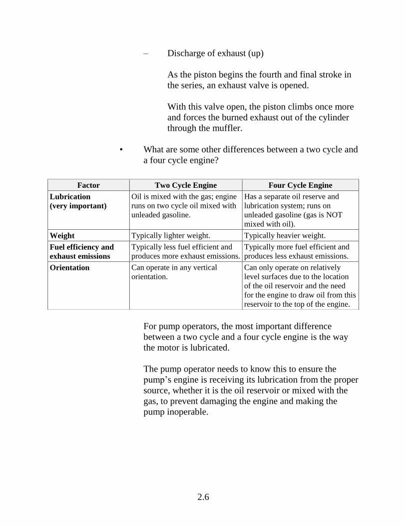
– Discharge of exhaust (up)
As the piston begins the fourth and final stroke in
the series, an exhaust valve is opened.
With this valve open, the piston climbs once more
and forces the burned exhaust out of the cylinder
through the muffler.
• What are some other differences between a two cycle and
a four cycle engine?
For pump operators, the most important difference
between a two cycle and a four cycle engine is the way
the motor is lubricated.
The pump operator needs to know this to ensure the
pump’s engine is receiving its lubrication from the proper
source, whether it is the oil reservoir or mixed with the
gas, to prevent damaging the engine and making the
pump inoperable.
Factor Two Cycle Engine Four Cycle Engine
Lubrication
(very important)
Oil is mixed with the gas; engine
runs on two cycle oil mixed with
unleaded gasoline.
Has a separate oil reserve and
lubrication system; runs on
unleaded gasoline (gas is NOT
mixed with oil).
Weight Typically lighter weight. Typically heavier weight.
Fuel efficiency and
exhaust emissions
Typically less fuel efficient and
produces more exhaust emissions.
Typically more fuel efficient and
produces less exhaust emissions.
Orientation Can operate in any vertical
orientation.
Can only operate on relatively
level surfaces due to the location
of the oil reservoir and the need
for the engine to draw oil from this
reservoir to the top of the engine.

2.7
2. Carburetor
The carburetor premixes vaporized fuel and air in proper proportions and supplies the mixture to the engine. If there is too much fuel mixed with air, the engine will either not run at all (flooded) or run poorly (smokes, stalls easily). If there is not enough fuel mixed with air, the engine will not run, and it could be damaged. The choke, throttle, and idle adjustment screws all play a role in how the carburetor works. It is important NOT TO ADJUST the low idle adjustment screw. With very little fuel entering the engine, there is very little oil entering as well. Poor adjustment of this low idle adjustment screw will cause severe engine damage. • When starting a cold engine, a very rich mixture of fuel
is needed.

2.8
The choke lever is in the “start” position; the choke is closed, which draws more fuel than air through the high idle adjustment screw. The throttle lever is in the “start” position; this opens the throttle to allow the fuel-rich mixture into the engine for the initial “cough” or “pop” of ignition.
• When the engine is idling, less fuel and air is needed to keep the engine running (compared to starting).
The choke lever is in the “run” position; the choke is open. The throttle lever is in the start-warm-up position. The negative pressure created by the piston movement inside the cylinder is now drawing a minimal amount of fuel and air to keep the engine running.

2.9
• When the engine is running at full throttle (maximum power), the maximum amount of fuel and air is needed.
The choke lever is on “run”; choke shutter is open. The throttle lever is on “full throttle”; throttle is open. At the high idle adjustment screw, liquid fuel is vaporized and mixes with the air to create the optimum firing mixture. At higher altitudes, the high idle adjustment screw may need to be adjusted to maximize pump performance (since oxygen in the ambient air varies with altitude). Improperly adjusting the high idle adjustment screw will diminish the pump’s performance.

2.10
3. Pump head (centrifugal)
There are different types of pump heads, but we are focusing on the centrifugal pump head. The pump operator needs to know: • How the water comes into the system
• How the water gains speed and velocity
• How the water exits the system
2.11
B. Parts of a High Pressure Pump
This section focuses on the parts of a high pressure portable pump. It
is important to first become familiar with the parts of the pump, then
in Unit 3 (Responsibilities) you will learn how to start, operate,
maintain, and troubleshoot the pump.
• Priming port
• Suction inlet (intake port)
• Pump head
• Spark plug and spark plug wire
• Muffler
• Spark arrestor
• Starter rewind
• Carburetor (behind air filter)
• Choke lever
• Overspeed reset rod
• On/off switch
• Throttle lever
• Air filter
• Fuel supply hose connect
• Pump release clamp
• Grease fitting

2.12
• Discharge port
• Electronic ignition
C. Types of Portable Pumps
This section discusses three general types of pumps. For each type of
pump, a general description, weight, type of fuel, and pump
performance are provided.
Pump performance is important because it helps determine whether
the pump is capable of providing the desired flow (gpm) and pressure
(psi) for the specific hose lay.
Refer to the Portable Pump Performance – National Cache Pumps
table (HO 2-1) for flow (gpm) and pressure (psi) for the different
types of pumps.
The data in this table comes from the Water Handling Equipment
Guide. Pump performance will be discussed in more detail in Unit 4
(System Design and Hydraulics).
2.13
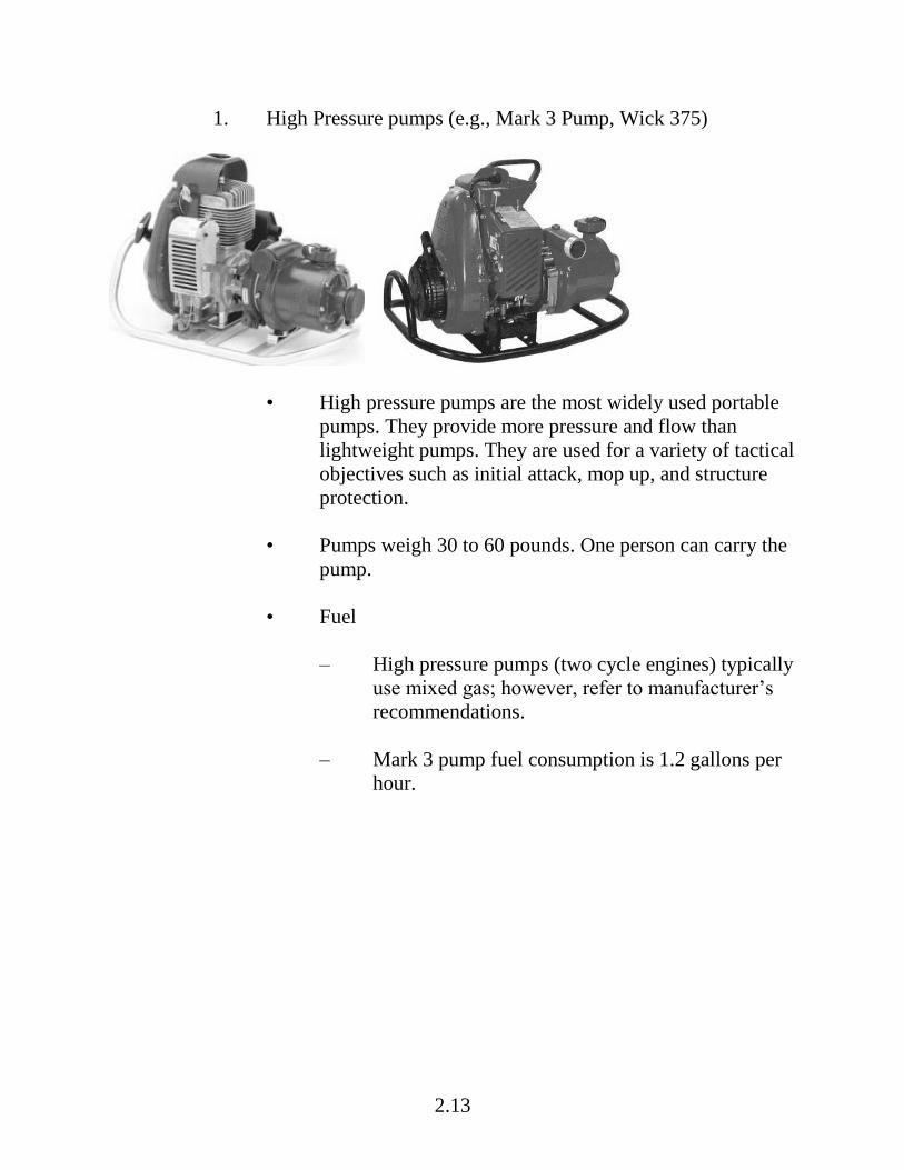
1. High Pressure pumps (e.g., Mark 3 Pump, Wick 375)
• High pressure pumps are the most widely used portable
pumps. They provide more pressure and flow than
lightweight pumps. They are used for a variety of tactical
objectives such as initial attack, mop up, and structure
protection.
• Pumps weigh 30 to 60 pounds. One person can carry the
pump.
• Fuel
– High pressure pumps (two cycle engines) typically
use mixed gas; however, refer to manufacturer’s
recommendations.
– Mark 3 pump fuel consumption is 1.2 gallons per
hour.

2.14
• Pump performance
– Refer to the Portable Pump Performance –
National Cache Pumps table (HO 2-1) and identify
the pump performance (gpm and psi) for high
pressure pumps.
– The IRPG is another reference for Mark 3 pump
performance data.
Note: The pump performance values in the IRPG
do not directly correspond with the values in the
Portable Pump Performance – National Cache
Pumps table (HO 2-1). Pump flows are normally
given in 50 psi increments (refer to Portable Pump
Performance – National Cache Pumps table [HO
2-1]), and the performance information in the
IRPG is done in 10 gpm increments.
– Pump performance will be discussed in more detail
in Unit 4 (System Design and Hydraulics).

2.15
2. Floatable pumps
• The floatable pump, which is similar to the high pressure
portable pump except it floats and has no suction hose, is
required. Floatable pumps are typically used on lakes
(especially if there is a rocky, steep shoreline); they are
also used in ditches and drop tanks.
• This pump weighs more than 60 pounds.
• Fuel
Floatable pumps (typically two cycle engine) fuel
requirements are variable; refer to manufacturer’s
recommendations.
• Refer to the Portable Pump Performance – National
Cache Pumps table (HO 2-1), and identify the pump
performance (gpm and psi) for floatable pumps.
2.16
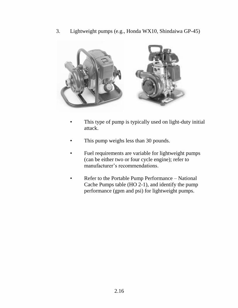
3. Lightweight pumps (e.g., Honda WX10, Shindaiwa GP-45)
• This type of pump is typically used on light-duty initial
attack.
• This pump weighs less than 30 pounds.
• Fuel requirements are variable for lightweight pumps
(can be either two or four cycle engine); refer to
manufacturer’s recommendations.
• Refer to the Portable Pump Performance – National
Cache Pumps table (HO 2-1), and identify the pump
performance (gpm and psi) for lightweight pumps.

2.17
II. HOSES
There are two types of hoses used in portable water delivery systems:
A. Suction (Intake) Hoses
Suction hoses are used to draft water; one end of the hose is connected
to the suction inlet (intake port) on the pump, and the other end is
placed in the water source.
Suction hoses are designed to handle vacuum and they are therefore,
always rigid.
They are usually furnished in 8- and 10-foot lengths.
B. Discharge Hoses
Discharge hoses carry water from the pump to the fire, portable tank,
or other location; one end is connected to the discharge port of the
pump. They are designed to handle pressure.
• The most common size of discharge hose used in wildland
firefighting include:
– ¾, 1, 1½, and 2½ diameters
– 50- and 100-foot lengths
• Material types (e.g., synthetic, woven fabric)
2.18
• Thread types
– National Pipe Straight Hose (NPSH)
– National Hose (NH)
– Garden hose thread (GHT)
• Important to use gaskets.
III. APPLIANCES, ACCESSORIES, AND TOOLS FOR HOSE LAYS
A. Appliances
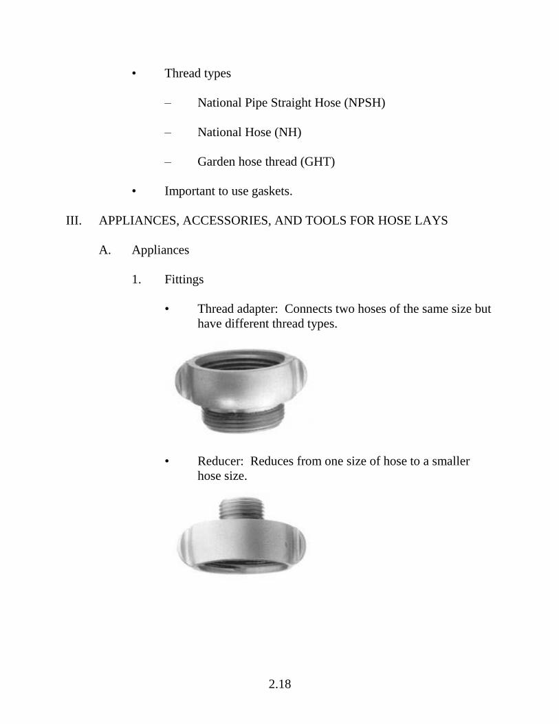
1. Fittings
• Thread adapter: Connects two hoses of the same size but
have different thread types.
• Reducer: Reduces from one size of hose to a smaller
hose size.

2.19
• Increaser: Increases from one size to a larger size.
• Double female: Connects two male ends of hose or
fittings.
• Double male: Connects two female ends.
2.20
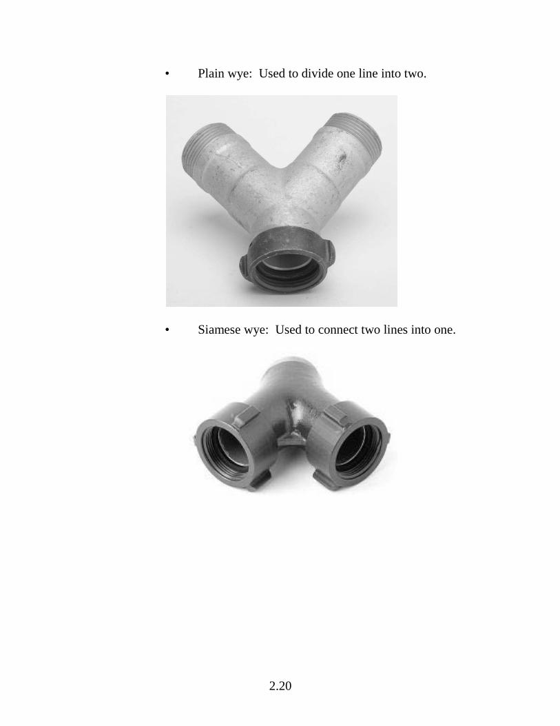
• Plain wye: Used to divide one line into two.
• Siamese wye: Used to connect two lines into one.

2.21
2. Valves
• Gated wye valve: Used to divide one line into two.
• Siamese gated wye valve: Used to unite two lines into
one.
2.22
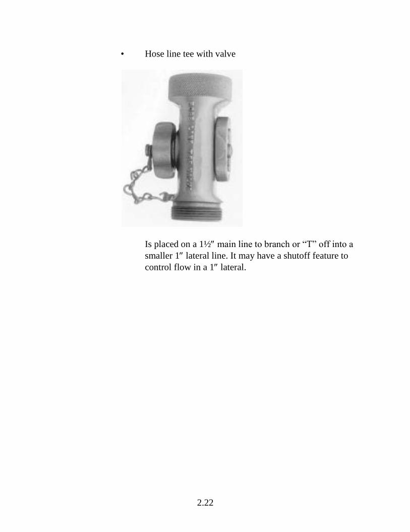
• Hose line tee with valve
Is placed on a 1½ main line to branch or “T” off into a
smaller 1 lateral line. It may have a shutoff feature to
control flow in a 1 lateral.

2.23
• Check and bleeder valve
The “check valve” helps maintain prime if the foot valve
isn’t working correctly; it also keeps water from flowing
back into the pump when the pump stops, and relieves
pressure on the pump when it is restarted.
The “bleeder” keeps the pump from overheating if all
discharge nozzles are shut off; the bleeder recirculates
the water back to the water source.
• Pressure relief valve
A spring-loaded, adjustable valve placed between the
pump and the discharge hose. Used to release excess
pressure on the pump due to kinks or nozzle shutoff.
2.24
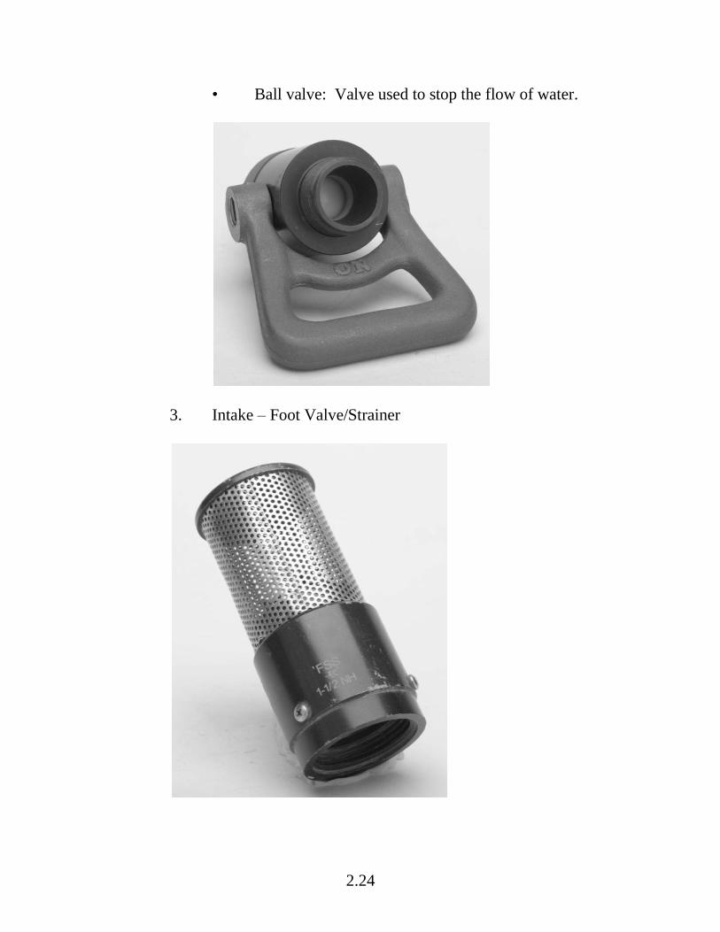
• Ball valve: Valve used to stop the flow of water.
3. Intake – Foot Valve/Strainer
2.25
Always use a foot valve/strainer to prevent damage to the
pump.
Most foot valves are a foot valve and strainer assembly. It is
spring loaded to prevent water from running out of the suction
hose as it is being primed or if the pump is shut off.
The strainer is a wire or metal guard used to keep debris from
clogging pumps. Due to environmental resource concerns,
smaller screens may be needed.
B. Hose Accessories and Tools
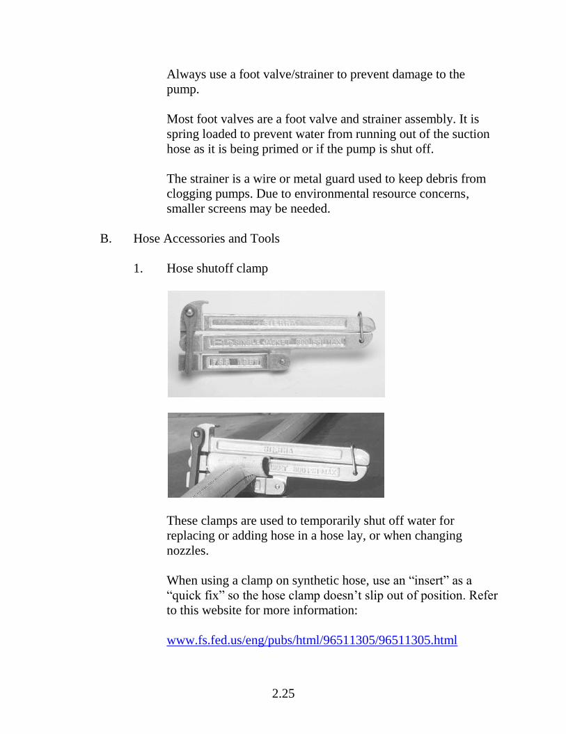
1. Hose shutoff clamp
These clamps are used to temporarily shut off water for
replacing or adding hose in a hose lay, or when changing
nozzles.
When using a clamp on synthetic hose, use an “insert” as a
“quick fix” so the hose clamp doesn’t slip out of position. Refer
to this website for more information:
www.fs.fed.us/eng/pubs/html/96511305/96511305.html

2.26
2. Spanner wrench
Used to loosen and tighten connections. Comes in many sizes
and shapes.
3. Gravity sock
Gravity socks can be used instead of pumps when water is
located at a higher elevation than the fire. The mouth of the
sock is placed in the stream and anchored securely. The tail is
attached to the fire hose.

2.27
IV. NOZZLES AND SPRINKLERS
A. Twin Tip Nozzle (Forester)
Refer to Types of Nozzles (HO 2-2) and review the General
Characteristics column for twin tip nozzles. The information in the
Tactical Use column will be covered in Unit 3 (Responsibilities).
B. Adjustable Barrel Nozzle (KK and Lexan)
Refer to Types of Nozzles (HO 2-2) and review the General
Characteristics column for adjustable barrel nozzles. The information
in the Tactical Use column will be covered in Unit 3
(Responsibilities).
C. Adjustable Barrel Nozzle – Garden Hose Nozzle (3/4 inch)
• Refer to Types of Nozzles (HO 2-2) and review the General
Characteristics column for adjustable barrel nozzle – garden
hose nozzle. The information in the Tactical Use column will
be covered in Unit 3 (Responsibilities).
D. Sprinklers
• Refer to Types of Nozzles (HO 2-2) and review the General
Characteristics column for sprinklers. The information in the
Tactical Use column will be covered in Unit 3
(Responsibilities).
• Sprinkler kits are discussed in the next section.
2.28
V. KITS
Kits contain most of the equipment and supplies needed for the water
delivery system; however, they don’t contain everything (e.g., fuel) and
sometimes some supplies are missing.
A. National Kits
• High Pressure Portable Pump Kit
• Lightweight Pump Kit
• Mop Up Kit
• Sprinkler Kit
B. Local Geographic Kits
Local geographic areas have their own kits, and kit contents will vary
by region.
2.29
VI. REVIEW
Question 1. In a two cycle engine, where is the oil located that lubricates the
engine?
Question 2. In a four cycle engine, where is the oil located that lubricates the
engine?
Question 3. Why is it important for the pump operator to know how the
engine is lubricated?
Question 4. Does a two cycle engine typically produce more or less exhaust
emissions than a four cycle engine?
Question 5. The fire is in a remote location (no roads), and you need a pump
that can provide a lot of pressure and flow? Which types of pumps would
work best?
2.30
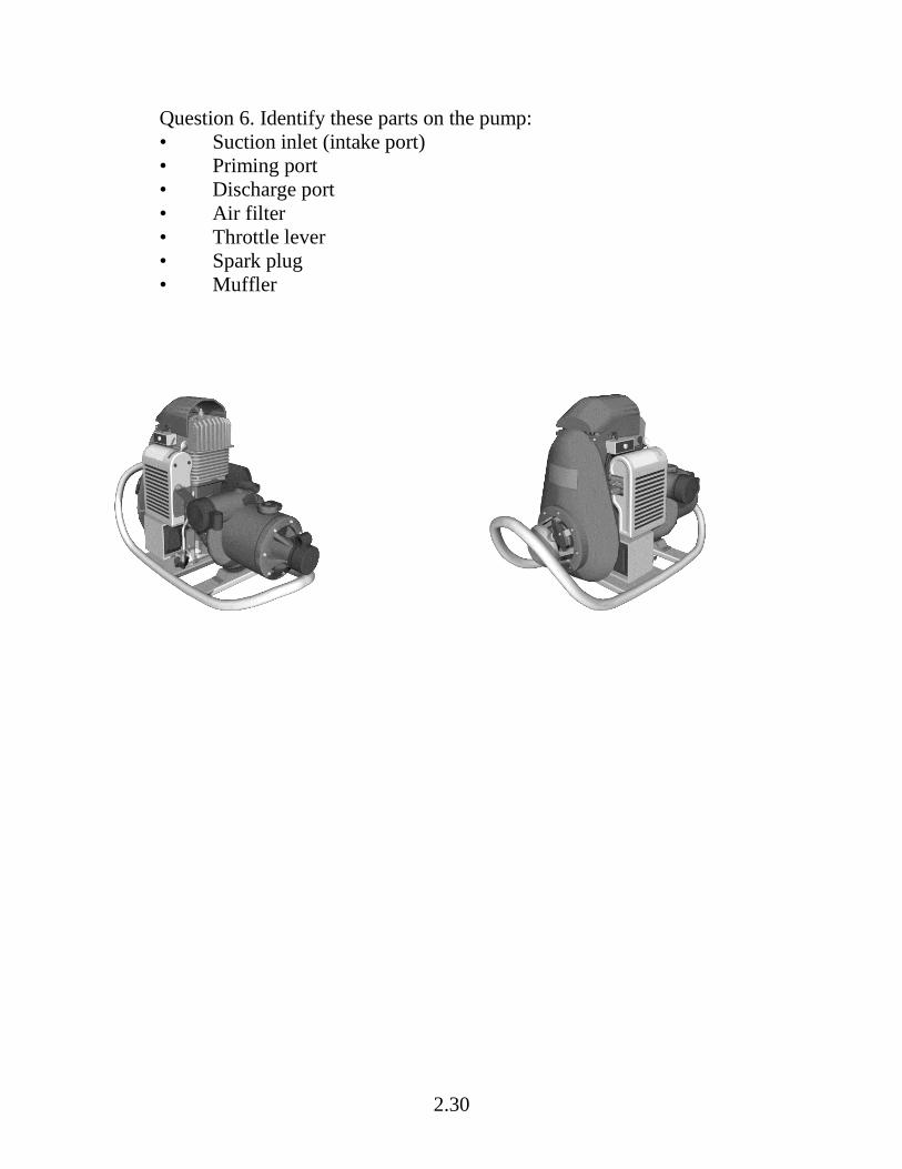
Question 6. Identify these parts on the pump:
• Suction inlet (intake port)
• Priming port
• Discharge port
• Air filter
• Throttle lever
• Spark plug
• Muffler
2.31
Question 7. What is the purpose of a suction hose?
Question 8. What is the purpose of a discharge hose?
Question 9. One of the purposes of this appliance is to help maintain prime if
foot valve isn’t working correctly. What is the appliance?
Question 10. The purpose of this appliance is to divide one line into two.
What is the appliance?

2.32
Question 11. What types of nozzles are these?
Question 12. There are several pump and pump-related kits that can be
ordered from the national cache. What are the names of those kits?

3.1
Portable Pumps and Water Use, S-211
Unit 3 – Responsibilities
OBJECTIVES: Upon completion of this unit, students will be able to: 1. Given scenarios and photos, identify risk management, fuel handing, and
environmental concerns. 2. Identify methods to prevent cavitation and water hammer. 3. List the four components that should be included in the design of a portable
water delivery system. 4. Given photos, critique a portable pump setup. 5. Identify how to prevent the engine from flooding when starting the pump. 6. Identify how to troubleshoot common problems with portable pumps. 7. Identify how to select nozzles and apply water to achieve tactical objectives. 8. List general guidelines for maintaining and retrieving hoses.

3.2
3.3
I. GENERAL RESPONSIBILITIES
This section discusses general responsibilities related to portable water delivery systems: risk management, environmental concerns, and communication. A. Risk Management
1. Always wear appropriate Personal Protective Equipment (PPE); keep sleeves down.
• The pump operator is required to wear eye and hand
protection during fueling operations, and ear protection is needed when operating the pump.
• The nozzle operator needs to wear eye protection to
prevent backsplash of hot or burning debris in the eyes.
2. Ensure LCES is established and known.
• The pump operator needs to maintain good situational awareness at all times and ensure good communications methods are in place.
• The nozzle operator is at high risk due to proximity to
fire.
3. When handling fuel, follow additional safety precautions:
• Do not operate a radio or any other portable electronic device such as a cell phone while engaged in fueling operations.
• Refer to the publication below for fuel handling and
transportation information.
Interagency Transportation Guide for Gasoline, Mixed Gas, Drip-Torch Fuel, and Diesel (online at www.nwcg.gov/pms/pubs/442/pms442.pdf )

3.4
4. Follow first aid guidelines in IRPG.
B. Environmental Concerns
Follow the directions given by your supervisor, Resource Advisor, or Agency Administrator regarding environmental concerns. Examples of environmental concerns include: • Fuel spill; notify supervisor or resource advisor.
• Species considerations:
– Sensitive species
– Invasive species (e.g., aquatic)
– Threatened and endangered species
• Minimize impact to site
– Keep area clean (dispose of garbage)
– Secure loose items (from wind)
• Rehabilitate site

3.5
C. Communication
1. Communication among the supervisor, pump operators, nozzle operators, and other fireline personnel is critical for safety and to meet tactical objectives.
• Supervisor needs to stay in close communication with
pump operator and nozzle operator.
• Pump operator communicates with:
– Nozzle operator when starting and shutting down the pump, and when troubleshooting.
– Supervisor if there is an environmental concern
(e.g., fuel spill), if there are equipment problems, or if more equipment is needed.
– Other fireline personnel to coordinate operations or
troubleshoot the system.
• Nozzle operator communicates with:
– Pump operator when there are problems with water discharging out of the system (i.e., not enough water or pressure).
– Pump operator and other nozzle operators about
number of nozzles that can be opened simultaneously.
– Other fireline personnel to coordinate operations or
troubleshoot the system.
2. Communication methods
Radio and hand signals are the typical forms of communication. Hand signals are typically used when the pump is running.

3.6
D. Prevent Cavitation and Water Hammer
1. Cavitation
Cavitation occurs when cavities or bubbles form in the water in the low pressure (suction side) of the pump, causing deep pits in the surface of the impeller. When cavitation occurs, it reduces the pump’s efficiency and can cause significant damage. Cavitation can occur rapidly. Cavitation is not a loss of prime. Common causes of cavitation include: • Restricted water flow (clogged strainer or defective
check valve)
• Air entering suction hose (water whirl, hole in suction hose, loose coupling)
• Suction hose diameter too big or too small.
• Downhill hose lay with extreme water demand
• High-altitude pumping
What are symptoms that cavitation is occurring?

3.7
To prevent cavitation: • Keep strainer clean and free of debris.
• Locate pump as close to water source as practical.
• Ensure adequate water supply.
• Ensure diameter of suction hose is accurate.
2. Water hammer
In a delivery system, water hammer occurs when flowing water is suddenly stopped, resulting in shock waves traveling back the length of hose at high speeds, producing rapid vibrations. The more water that is flowing through the hose, the more danger there is and the greater the potential for injury to the nozzle operator. The most common causes of water hammer are when a valve is closed suddenly at an end of a line; or vehicles driving over hose. What are symptoms that water hammer is occurring or has occurred?

3.8
What can a pump or nozzle operator do to prevent water hammer? • Slowly close valves and nozzles.
• Keep nozzles slightly cracked open at all times.
• Protect hoses from being driven over.
We have just covered general responsibilities related to portable water delivery systems. Now it is time to do an exercise.
3.9
EXERCISE: Pump Accident Investigation Report Purpose: Students will read the State of Alaska Accident Investigation Factual Report and discuss. Materials needed: State of Alaska Accident Investigation Factual Report Directions 1. Read the report and answer the questions.
Question 1. What task was the Idaho City crew assigned on July 9? Question 2. A member of the Idaho City crew was assigned to be the pump operator. What task was assigned? Question 3. Briefly outline how the accident happened.
3.10
Question 4. What were the three causal factors and findings identified in the report? Question 5. What did you learn from reading this report?
2. Participate in a large group discussion on questions and answers. End of Exercise.

3.11
II. DESIGN RESPONSIBILITIES
Typically the squad boss or crew boss has overall responsibility for designing portable water delivery systems, especially more complicated delivery systems. However, an experienced pump operator will often design simpler systems. A. Mental Image and Design Schematic
For simpler delivery systems, a mental image of the design is all that is needed. However, as delivery systems get more complicated, it is essential to plan ahead and develop a schematic on paper to ensure the delivery system will work efficiently and effectively. How to draw this schematic will be covered in Unit 4 (System Design and Hydraulics).
B. Designing the Delivery System
When designing the delivery system, remember to consider the tactical objectives, resources (personnel and equipment), and site characteristics. Incorporate these components into the design. • Portable pump configurations
Review Portable Pump Configurations.
• The information on pressure, flow, and friction loss will be discussed in Unit 4 (System Design and Hydraulics).

3.12
• Hose lay design
Review Types of Hose Lays. The information on pressure, flow, and friction loss will be discussed in Unit 4 (System Design and Hydraulics).
• Nozzle type(s)
Refer to Types of Nozzles (HO 2-2), which was already discussed in Unit 2 (Equipment).
• Hydraulic calculations, as appropriate
Remember, the system needs to be hydraulically feasible – it needs to work. Include the hydraulic calculations on the schematic, as appropriate. Hydraulic calculations will be discussed in Unit 4 (System Design and Hydraulics).
III. PORTABLE PUMP RESPONSIBILITIES
This section discusses the responsibilities related to operating portable pumps. Some pumps have a reputation of being difficult to operate, but in many situations the problems with the pump could have been prevented by the pump operator. Getting as much experience as you can is essential to becoming a good pump operator. There are some excellent references to use in the field when working with portable pumps. • High Pressure Portable Pump Instructions (comes in the kit)
• IRPG – Mark 3 Pump Information

3.13
This section discusses seven general steps involved with operating a single pump. • Obtain equipment and supplies.
• Set up and prime pump; connect hoses.
• Mix gas and oil, and refuel.
• Start pump.
• Operate and maintain pump.
• Shut down pump.
• Troubleshoot.
A. Obtain Equipment and Supplies
1. Pump or pump kit
Typically, the pump operator’s supervisor or someone else orders the pump kits. Often they will order extra pump kits to have as a backup.
2. Other equipment supplies
The pump operator needs to bring other equipment and supplies (e.g., fuel, discharge hoses, shovel, and nozzles).
3.14
B. Set Up Pump, Connect Hoses, and Prime Pump
1. Select a site that is easily accessible. You will not always get an ideal site.
• Find water source: Factors to consider include:
– Amount of water available
– Minimum of 1 foot deep
– Cleanliness
– Distance from fire
– Environmental concern
• Find flat ground or create flat ground; need enough room
for two containment berms.
• Keep suction lift as low as possible.
• Minimize impact to site.
2. Unpack kit; inventory and inspect equipment for damage.
• Look for loose nuts or bolts, cracked suction hose, damaged threads, inoperative valves, holes in hose, and any other defects.
• Flag defective items; identify the defect, problem, or
symptom, and then return item.
• Tie hose in knot if something is wrong with it.
• Keep track of all contents in the kit so when it is repacked, everything is accounted for.

3.15
3. Set up containment berms.
• Unfold both berms and ensure sides are fully extended. Remember to use two berms (one berm for the pump and the other for the fuel can).
• Place absorbent pads in berms. In rough or rocky terrain,
use two pads in pump berm.
• Pads serve two purposes – to absorb fuel that is spilled and to protect the integrity of the berm.
4. Place high pressure pump in one containment berm and the fuel
can in the other berm.
• Important: Because the pump engine has so many potential ignition sources, it is important to keep the fuel tank as far away from the engine as possible to avoid the ignition of any spilled or leaking fuel or fuel vapors.
• Orient pump so exhaust does not vent directly on fuel
can.
5. Secure pump and fuel can, if necessary, to prevent creep and to maintain position.
Now that the pump, fuel can, and berms are set up, it is time to connect the hoses and prime the pump.
6. Connect foot valve/strainer to male end of suction hose; then fill suction hose with water and connect to pump (suction side connections should be wrench-tight).
7. Place foot valve at least 1 foot under water.
Keeping strainer clean and free of debris; puts strainer on a shovel, in a bucket, or other method to prevent it from becoming clogged with mud or gravel.
3.16
8. Prime the pump by filling the priming port with water. Fill to the brim and wrench tighten cup. Fill the primary port using a hand primer or a pail.
9. Connect hose curl (pigtail) to discharge side of pump and the
other end of hose curl to check and bleeder valve. 10. Utilize 1" port on check and bleeder valve to recirculate water
back to the water source.
The pressure relief valve can be added to the system to protect the pump from water hammer.
C. Mix Gas and Oil, and Refuel
• Safety procedures when working with fuel:
– ALWAYS wear eye protection and gloves.
– ALWAYS shut the pump down before opening the fuel tank.
An operating pump engine has several potential sources of ignition including the muffler, exhaust, and electrical system. All of these ignition sources can be eliminated by shutting down the engine and allowing the exhaust to cool before opening the fuel tank.
– NEVER operate a radio, cell phone, or other portable electronic device when working with fuel.

3.17
• Fuel and environmental concerns
– Pumps and fuel cans often leak; preventing fuel from entering the water or ground is critical.
– ALWAYS uses containment berms and absorbent pads.
– ALWAYS mix fuel over the containment berm.
– If a spill occurs or fuel enters the water source, contain
the spill, ensure no more fuel is spilled, and notify supervisor, Resource Advisor, or both, immediately. Spill containment kits are available at district office and Incident Command Post.
– If fuel has to be transported or stored, follow agency
policy.
Refer to this publication: Interagency Transportation Guide for Gasoline, Mixed Gas, Drip-Torch Fuel, and Diesel (online at www.nwcg.gov/pms/pubs/442/pms442.pdf)
• All two cycle pumps require unleaded gas mixed with two cycle oil.
3.18
• Determine if the fuel is pre-mixed.
– Pre-mixed fuel should be identified with a yellow tag (2-stroke mix) on the fuel can. The fuel is typically red or greenish (darker than straight gas), and slippery to the touch.
Alaska and other areas provide pre-mixed fuel. If fuel is pre-mixed, it is ready to use.
– Regular gas should be identified with a red tag; the gas is typically straw colored or clear (has no color).
If the gas is unmixed, it needs to be mixed with two cycle oil.
• Fuel mixing instructions if the fuel was not pre-mixed:
– Determine quantity of regular gas and two cycle oil that needs to be mixed. Follow manufacturer’s recommendation of 24:1.
For every 5 gallons of gas, add approximately 1 quart of oil.
– Pour approximately 1 gallon of gas and an appropriate amount of two cycle oil into fuel can, and shake vigorously.
– Add remainder of gas.
• Write on tag the date the fuel was mixed and attach tag to fuel
can.
• Attach fuel line to pump-adapted fuel can.
• Replace fuel absorbent pads as needed by placing them in garbage bags (kit) and disposing of used pads according to local protocol.

3.19
D. Start Pump
Follow these steps to start the pump. It is easy to flood the engine, so be careful. • Communicate to the nozzle operator(s) that pump is ready to
start.
• Don’t start pump until nozzle operators have confirmed that they are ready for water.
• Open air vent on fuel can.
• If engine is cold, move the choke lever to start position. If
engine is warm, move the choke lever to run position.
• Move throttle lever to start/warm up position.
• Slowly pump fuel bulb until fuel mixture (in clear fuel tube) is just touching bottom of carburetor.
Caution – Follow this step carefully to avoid flooding the engine: • If pump is equipped with an on/off switch, turn the switch on.
• On Mark 3 pump, ensure overspeed reset rod is pushed in.
• Pull starter rope with short, quick pulls (typically two to four
pulls) until engine “pops.”
• Immediately set choke lever to run position.
• Pull starter rope approximately one to three more times, and the pump engine should start.
Caution – Any additional pulls of rope with choke in start position (after engine pops) will flood the engine.
3.20
• Allow engine 2 minutes to warm up (throttle lever should still be at start/warm up position) before moving throttle to run position.
E. Operate and Maintain Pump
• Prevent pump cavitation and water hammer.
• Ensure water is flowing through the pump head at all times. Crack nozzle open or open bleeder valve.
• Grease pump head with one squirt of grease once a shift (or
every 8 to 12 hours) at grease/zerk fitting.
• When pump is shut down for fueling or maintenance, tighten any loose nuts and bolts.
• Listen to the pump for indicators of how it is operating. The
following are examples of sounds that may indicate problems with the pump or hose lay:
– Lugging sound might indicate the pump’s nozzle shut
down, or there is a closed valve or kinked hose, or there are hydraulic or mechanical problems.
– Rapidly increasing sound (revolutions per minute [rpm]
increasing) may be a sign the pump has lost its prime, or there is a broken hose, broken suction hose, or an open nozzle.
– Sputtering sound might indicate dirty air filter, bad fuel,
or the pump’s carburetor needs adjusting.

3.21
The pump’s carburetor is set to operate at specific elevations. A significant elevation change may cause fuel/air mixture problems and will result in the carburetor not working correctly. Consult with your supervisor or follow local policy, or both, regarding adjustment of the carburetor. If adjusting the carburetor is not allowed, flag the pump (identify problem on the flag) and return it to be fixed. If you have permission to adjust the carburetor, follow these steps but be extremely careful because you may damage the pump.
1. When the pump’s engine is warm, run the pump at full throttle. 2. Slowly turn the high idle adjustment screw (with tabs) until
maximum rpm is reached and passed (audible change). 3. Turn the high idle adjustment screw the opposite direction until
maximum rpm is reached again. 4. Finally, turn the high idle adjustment screw counterclockwise ¼
of a turn to obtain both maximum rpm and proper engine lubrication.
• Note: It is very important NOT TO ADJUST the low
idle screw. Maladjustment of this screw will cause severe engine damage.

3.22
F. Shut Down Pump
Follow these steps when shutting down the pump: • Communicate with the nozzle operator that you are ready to
shutdown the pump.
• Move the throttle lever to the “stop” position.
• Pull the male end of the fuel line quick-connect from the base of the fuel tank, and hold the fuel line (with fuel line still attached to the pump) above the tank to drain the fuel line. The pump will run at a low idle and have ample time to cool down and will stop due to the lack of fuel.
• In freezing conditions, drain the pump head.
G. Troubleshoot Problems With Pump
This section starts with a video on how to troubleshoot problems with the pump. Then two different approaches to troubleshooting will be described. 1. Troubleshooting video
This video was produced before the current guideline, which describes the use of two berms (one berm for the pump and one for the fuel), was developed. The characters did not always wear full PPE or follow all proper fuel handling procedures. When the engine flooded, the characters should not have checked for a spark.
2. Troubleshooting – symptoms and remedies
Refer to Troubleshooting Portable Water Delivery Systems (IR 3-2) for a list of common symptoms, causes, and remedies. This list specifically addresses problems with pump – it does not address problems with the suction hose.

3.23
3. Troubleshooting using IRPG (step-by-step process) as a reference.
4. Troubleshooting using the High Pressure Portable Pump
Instructions (step-by-step process) as a reference.
The step-by-step process in the High Pressure Portable Pump Instructions (which is similar to the IRPG) is an excellent reference when troubleshooting. It comes in the High Pressure Portable Pump Kit. The information in this reference is not in the Student Workbook, so it is very important to review each step listed on this reference.
5. Additional troubleshooting issues (not addressed in the IRPG or High Pressure Portable Pump Instructions) include:
• Check the air filter
Clean the air filter by removing it from the assembly, and clean it according to manufacturer’s specifications. Reinstall the air filter components in the order they were removed (screen before filter).
• If the starter assembly is broken, follow these steps:
– Remove the starter housing to expose the manual pull cord starter assembly. Use caution around the pump after removing the starter housing as the starter is fully exposed and if you accidently touch it you will be severely injured.
– Wrap a piece of rope or cord around the starter
assembly, and pull to start the pump.
3.24
6. Use flagging to identify mechanical or other problems with the pump.
We have just covered pump operator responsibilities from risk management to troubleshooting. Now it is time to address nozzle operator responsibilities.
IV. NOZZLE RESPONSIBILITIES
The nozzle operator’s close location to the fire increases his or her risk of injury. Also, if a simple hose lay is used, the nozzle operator does not have as much protection. A. Select Nozzle(s)
• Twin tip nozzles
• Adjustable barrel nozzles
• Sprinklers
Refer to Types of Nozzles (HO 2-2) in Unit 2 (Equipment) for more information.
B. Apply Water
General guidelines for applying water include: • Situations where straight stream is appropriate include:
– Fire is too hot to get close.
– Fire is confined to small area.
– Need to reach longer distances (snags, tree tops, hot roots
or beds).
3.25
• Situations where fog or spray nozzle is appropriate include:
– Hot spotting, wet lining, direct attack, and mop up.
– Close work is needed.
– Fire covers a larger area.
– A smaller volume of water is required to put out the fire or water conservation is necessary.
• Approach fire with charged hose.
• Aim at base of flame, and maintain water stream in sweeping
motion.
• Avoid excessive water pressure.
High water pressure will deliver air as well as water to the fire and can fan the flame rather than knock it down. Excessive pressure wastes water while low pressure may not penetrate to the base of the flame.
• Watch for flare-ups.
• Conserve water (e.g., use low-flow nozzles, shut off as appropriate, apply water intermittently).

3.26
Would you use straight stream or fog spray in each of the following four fire situations?
Image #1
Image #2

3.27
Image #3
Image #4

3.28
C. Operation and Maintenance
• Slowly open and close all valves including nozzles to prevent water hammer.
• Unclog nozzle tips.
D. Communication
It is important to communicate up and down the hose lay to know how many nozzles can be open at a time. A hose lay may have 15 laterals, but sometimes the pump can only support 3 or 4 nozzles being open simultaneously.
V. HOSE LAY RESPONSIBILITIES
The pump operator, nozzle operator, or others (i.e., hand crews) may be involved with setting up, maintaining, and retrieving hose lays. A. Set Up Hose Lay
There are numerous methods for setting up hose lays. A couple of methods are listed below: • Simple hose lay
A crew first extends a trunk line (main hose line) from the pump to the fire as a simple hose lay; one nozzle is attached. Start with your largest hose, and then attach smaller hoses. Male fitting faces fire and female fitting faces water sources.
3.29
• Progressive hose lay (hose lay with laterals lines)
If lateral lines are needed, the crew can install a gated wye and proceed 100 feet with the trunk line to install another gated wye, which has a 1½″ to 1″ reducer on one side (towards the fire) and attach 100 feet of 1″ hose with the preferred nozzle. One person can then operate this nozzle to attack the fire as another person extends the next section of the trunk line, which is attached to the remaining side of the gated wye. Once the trunk line is extended and the second lateral gated wye is in place, the first nozzle operator then charges the trunk line and returns for more hose once the second lateral attack line is flowing water. This process is repeated until the fire is contained or the pump has reached capacity. Note: An inline T or other branching appliance could be used instead of the gated wye.
B. Maintain and Retrieve Hose Lay
General guidelines for maintaining and retrieving hoses include: • Replace protective caps on accessories and male hose ends.
• Be sure female ends have a gasket.
• Replace broken hose and check for kinked hose.
• Keep hose line out of hot spots.
• Use accepted method of rolling hose when retrieving, e.g.,
figure eight or a roll. And reconnect male end into female end to protect threads.
• Properly store hose in a safe location (away from fire, not in a
dozer’s path, etc.)

3.30
VI. SETTING UP MULTIPLE PUMP SYSTEMS
This section discusses how to set up series, parallel, and staged pumping systems. Refer to Portable Pump Configurations for a review of these systems. A. Series Pumping
1. Set up Pump 1.
• Set up first pump near water source, and prime the pump.
• Attach the short section of 1½″ hose to the pump discharge port, and attach a check and bleeder valve to the 1½″ hose.
• Attach 1″ hose to check and bleeder valve to serve as
pump protection and pressure relief.
• Attach the female end of the hose you will use to connect the two pumps to the check and bleeder valve. The length of the connecting hose is dependent on the ability of the first pump to supply enough volume to the second pump.
2. Set up Pump 2.
• Attach a 1 ½″ double female coupling to the suction port. In some instances, it may be necessary to reduce the 2″ suction to 1½″.
• Connect the hose from the first pump to the double
female.
• Connect a check bleeder valve to the discharge port using a short section of 1½″ hose.
3. Double check all fittings and connections to prevent damaging
pump or blowing hoses (due to increased pressure).

3.31
4. Start Pump 1.
• Start first pump and allow pump to warm up (water should be flowing toward the second pump).
• Bring pump up to full operating speed.
• Ensure water is flowing into the second pump. The
connecting hose should be firm.
5. Start Pump 2.
• Start Pump 2 and allow it to warm up.
• Slowly increase the speed of the second pump. The connecting hose should be monitored continually during operation.
If the hose appears to quiver or go flat, the pump may be damaged (cavitation). This is because the second pump is drawing more water than the first pump can supply. Slow down the second pump or increase the speed of the first pump.
6. Monitor fuel levels.
• Fuel levels must be monitored continually during the operations. ALWAYS shut down pump before checking fuel level or when refueling. Pumps will consume fuel at various rates based on inherent differences in the carburetor adjustments, throttle speeds, and mechanical conditions.

3.32
7. Shutdown procedures
• Open the check and bleeder valve of Pump 2. This will reduce head pressure on the second pump.
• Slow down Pump 2 to idle speed for cool down.
• Slow down the Pump 1 to idle speed.
• After both pumps have cooled down, turn them off.
B. Parallel Pumping
Typically, one pump operator should be able to handle all setup and operation.
1. Set up two pumps. Pumps should be relatively close together.
• Attach a check and bleeder valve to each pump using a short 1½″ hose. The purpose of the check and bleeder valve in the line is to prevent head pressure and one pump from pumping back into the other.
• Use a Siamese or invert a 1½″ gated wye by attaching a
double male to the female end and two double females to the male ends of the wye. This allows for the connection of two pumps into one hose.
• Attach the Siamese or inverted wye to the discharge hose
of each pump using a length or lengths of hose.
2. Either pump may be started or stopped at any time without affecting the other.
3. Monitor fuel levels. ALWAYS shut down pump before
checking fuel level or when refueling.

3.33
4. Shutdown Procedures
• Slow down both pumps to idle speed to cool down pumps.
• Turn off pumps; they can be shut off in any order as long
as there is a check and bleeder valve on the discharge side of each pump.
C. Staged Pumping
The steps for setup, operation, and shutdown for a staged pumping system are the same steps used if you are using a single pump.
VII. CHEMICALS (OPTIONAL)
Chemicals are sometimes used with portable pumps. There are several types of wildland firefighting chemicals. The specific requirements, uses, and tactics for each type depend on the characteristics of the type of product. A. Types of Chemicals
1. Water enhancers
Water enhancers contain ingredients designed to alter the physical characteristics of water to increase effectiveness, accuracy of the drop, or adhesion to fuels. They also improve the ability of water to cling to vertical and smooth surfaces. Once the water has evaporated, water enhancers are no longer effective. This makes them well suited for direct attack or short-duration indirect attack. They are also well suited to protection of structures and other vertical surfaces, as the viscosity and stickiness of the products reduces runoff and retains more of the product on the fuels. The duration of effectiveness will depend on temperature, humidity, and exposure to UV (sunlight).

3.34
Water enhancers are supplied as wet or dry concentrates. They can be batch mixed or blended through proportioning equipment. Because some of these products are sensitive to the amount of shear that they are exposed to, during mixing, manufacturers’ recommendations should be followed. Water enhancers are sensitive to water quality, and hard water will require a higher mix ratio than softer water to achieve the same consistency. Most are approved for use over a range of mix ratios to allow the user to obtain the consistency needed for the task. The water enhancers are typically applied from helicopters, Single Engine Air Tankers (SEATs), and ground equipment.
2. Long-term retardants
Long-term retardants contain retardant salts (typically fertilizers) that alter the way the fire burns, decreasing the fire intensity and slowing the advance of the fire, even after the water they originally contained has evaporated. Because long-term retardants continue to work after the water they contain has evaporated and continue to work for days or weeks until they are removed by rain or erosion, they are well suited for indirect and line building. These products can be used for direct attack, but they are only marginally more effective than water for this use. Retardants can be supplied as wet or dry concentrates. They have been developed to provide mixed product within a specific viscosity level. These concentrates are mixed with water at a mix ratio determined during the evaluation process. Mixing can occur at tanker bases and portable mixing sites to produce mixed retardant. Application of long-term retardants is usually from fixed-wing air tankers and helicopters, but they may also be applied from ground equipment.

3.35
3. Foam fire suppressants
Foam fire suppressants contain foaming and wetting agents like those found in dishwashing detergents and other cleaners. The foaming agents affect the accuracy of an aerial drop, how fast the water drains from the foam, and how well the product clings to the fuel surfaces. The wetting agents increase the ability of the drained water to penetrate fuels. Foams depend on the water that they contain to suppress the fire. Once the water has evaporated, foams are no longer effective. This property makes them most effective for direct attack and mop up. Appropriate selection of concentrate dilution and application equipment will yield suppressants having a range of characteristics desirable for specific conditions: a. Fast draining foam for penetration and wetting to attack
deep seated fires and mop up. b. Fluid foam with moderate drain times for wet line. c. Dry, sticky foam with slow drain times for exposure
protection. Foam fire suppressants are supplied as wet concentrates. These concentrates can be batch mixed, blended with a proportioner, or prepared with a compressed air foam system. Foams are typically applied from helicopters and ground equipment, although they may also be applied from SEATs. Some agencies may also apply foams from water-scooping aircraft.

3.36
B. Personal Safety
The material safety data sheet for each product must be available in the workplace. By following the recommendations for personal protective gear and safe handling procedures you will minimize your exposure to these products and any irritation they may cause. Common recommendations are that safety goggles be worn by anyone using concentrated liquid products such as foam concentrates, and dust masks should be worn when mixing dry concentrate retardants. Chapping and dry or cracked skin may occur with frequent or prolonged exposure to the drying effects of any of the fire chemicals. Washing any of these products off your skin as soon as possible and using a hand cream or protective lotion to minimize chapping is a good idea regardless of the products you are using.
C. Environmental Concerns
Most of the products have been evaluated for toxicity to fish. Because all of the products are toxic to fish to some extent, care should be taken to minimize the possibility of accidental contamination of all waterways. Chapter 12 of the Interagency Standards for Fire and Fire Aviation Operations contains specific guidelines and exceptions to these guidelines. All firefighters should become familiar with these guidelines and the actions to be taken if fire chemicals are introduced into the waterway. For most firefighters, their responsibility is to tell their supervisor if they see fire chemicals in a waterway, application of fire chemicals that impacts a waterway, or something that suggests that fire chemicals were introduced to a waterway.
3.37
VIII. REVIEW
Question 1. There is a fuel spill. What should you do?
Question 2. What are some risk management issues specific to operating a portable pump and hose lay? Question 3. What are the four components that should be included in the design of a delivery system?
3.38
Question 4. Critique this pump set up (see photo on slide). Question 5. When fueling or refueling, what are safety procedures the pump operator should follow? Question 6. When you start the pump, what can you do to prevent flooding the engine?
Question 7. You hear the pump lugging; what could be the problem?

3.39
Question 8. You hear the pump having rapid rpms. What could be the problem? Question 9. What could cause the pump to lose its prime? Question 10. What can a pump operator do to prevent pump cavitation? Question 11. What can a pump and nozzle operator do to prevent water hammer?

3.40
Question 12. In what situations would it be advantageous for the nozzle operator to use the straight stream? Question 13. In what situations would it be advantageous for the nozzle operator to use the fog/spray? Question 14. What are some general guidelines for applying water? Question 15. What are some general guidelines for maintaining and retrieving hoses?
SR 3-1
Page 1 of 10
State of Alaska
Department of Natural Resources Division of Forestry
Director’s Office 550 W. 7th Ave., Suite 1450 Anchorage, Alaska 99501-3566
Safety Office 101 Airport Road, Aviation Hanger Palmer, Alaska 99645
This document is intended as a safety and training tool, an aid to preventing similar future occurrences, and to inform interested parties. The information contained in this report is subject to revision upon further investigation and/or should additional information become available.
ACCIDENT INVESTIGATION FACTUAL REPORT
Type of Incident:
Water Supply / Burns
Location: AK-DOF, Fairbanks Area, Logging Slash Fire, Alaska
Date of Accident/Incident:
July 9th, 2009
Investigation Team Members:
Rocky D. Ansell, Statewide Safety Officer, State of Alaska, Division of Forestry, Palmer
Tom Kubichek, Alaska Smokejumpers Air Operations Supervisor, BLM/AFS, Fairbanks Mike Spencer, Safety Officer / Training Specialist, Pacific N/W Regional Office, USFS

SR 3-1
Page 2 of 10
Special commendations are warranted for the quick actions of the other personnel present on the Logging Slash Fire. They quickly reacted to the situation, encouraged the Pump Operator to “Stop, Drop and Roll” and provided immediate emergency care. These actions greatly reduced the degree of injury and significantly reduced the recovery time of the injured party. Christian Blankenship Incident Commander Glen Farnsworth Operations Avi Shalom Fairbanks Area WFRT IV Mike Goyette Fairbanks Area Prevention Officer The investigation team would like to thank everyone assigned to the Minto Flats South IMT (Alaska Type 2 Green Team) for their cooperation. Rob Allen Incident Commander Kato Howard Operations Section Chief Rich Webster Safety Officer Terri Berrie Medical Unit Leader
Per the guidance provided to the investigation team by the Agency Representatives, this investigation utilized a modified After Action Review format. The investigation team referenced the following documents for guidance in their efforts to obtain information, complete their findings and document this incident:
Interagency Standards for Fire and Fire Aviation Operations 2009 o Chapter 7, Safety & Risk Management o Chapter 18, Reviews, Investigations & Analyses
State of Alaska, Policies and Procedures Manual, Section 2165
Summary At approximately 1857 hours (ADST) on July 9th, 2009 while supporting a water pumping operation, a member of the Idaho City IHC was burned while working on the Logging Slash Fire in interior Alaska. The Idaho City IHC Crew Member was assigned the operation of a Mark 3 pump to support a water pumping function utilizing a folda-tank and Mark 3 pump. During a routine check of the fuel supply the crew member opened the Jerry can (fuel tank); flammable liquid and vapors spewed from the container and were ignited. The resulting flash fire burned the crew member. Investigation reveals the jerry can, during set-up of the pump, was placed in close proximity to the Mark 3 exhaust (muffler). During the interval that the pump was running the exhaust did impinge upon the jerry can preheating the gasoline. Upon opening the bung of the jerry can; volatile gasoline vapors and liquid escaped and were ignited by the muffler/hot components of the Mark 3 pump. Portable fire extinguishers were used to extinguish the fuel can, pump and other burning objects that had been ignited by the flash fire.
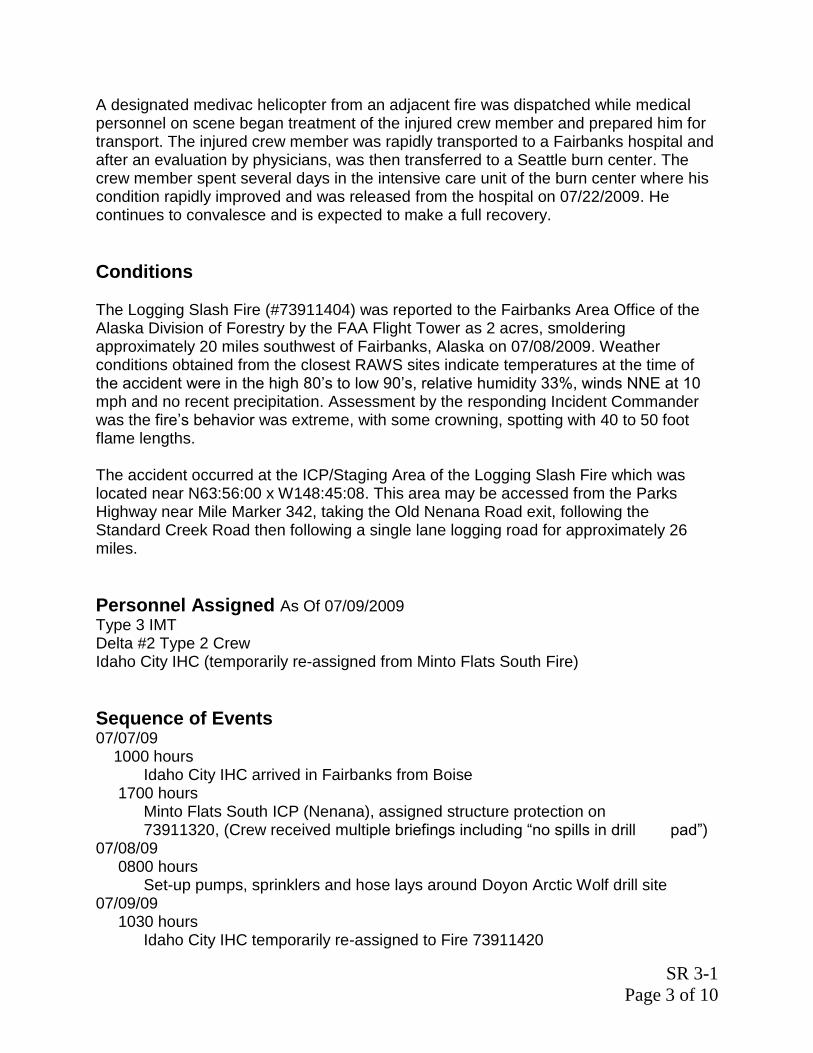
SR 3-1
Page 3 of 10
A designated medivac helicopter from an adjacent fire was dispatched while medical personnel on scene began treatment of the injured crew member and prepared him for transport. The injured crew member was rapidly transported to a Fairbanks hospital and after an evaluation by physicians, was then transferred to a Seattle burn center. The crew member spent several days in the intensive care unit of the burn center where his condition rapidly improved and was released from the hospital on 07/22/2009. He continues to convalesce and is expected to make a full recovery.
Conditions The Logging Slash Fire (#73911404) was reported to the Fairbanks Area Office of the Alaska Division of Forestry by the FAA Flight Tower as 2 acres, smoldering approximately 20 miles southwest of Fairbanks, Alaska on 07/08/2009. Weather conditions obtained from the closest RAWS sites indicate temperatures at the time of the accident were in the high 80’s to low 90’s, relative humidity 33%, winds NNE at 10 mph and no recent precipitation. Assessment by the responding Incident Commander was the fire’s behavior was extreme, with some crowning, spotting with 40 to 50 foot flame lengths. The accident occurred at the ICP/Staging Area of the Logging Slash Fire which was located near N63:56:00 x W148:45:08. This area may be accessed from the Parks Highway near Mile Marker 342, taking the Old Nenana Road exit, following the Standard Creek Road then following a single lane logging road for approximately 26 miles.
Personnel Assigned As Of 07/09/2009
Type 3 IMT Delta #2 Type 2 Crew Idaho City IHC (temporarily re-assigned from Minto Flats South Fire)
Sequence of Events
07/07/09 1000 hours Idaho City IHC arrived in Fairbanks from Boise 1700 hours Minto Flats South ICP (Nenana), assigned structure protection on 73911320, (Crew received multiple briefings including “no spills in drill pad”) 07/08/09 0800 hours Set-up pumps, sprinklers and hose lays around Doyon Arctic Wolf drill site 07/09/09 1030 hours Idaho City IHC temporarily re-assigned to Fire 73911420

SR 3-1
Page 4 of 10
1857 hours Accident occurs, burning Idaho City IHC crew member 1952 hours Burn victim arrives Fairbanks Memorial Hospital via Helicopter N16973 2315
Burn victim prepared for transport to Seattle via Guardian Flight, Inc – estimated flight time 3.5 hours
Narrative Five Type 1 crews were mobilized from the Lower-48 to Alaska to support multiple incidents. The Idaho City IHC (IC-IHC) was one of these crews. The IC-IHC was assigned to the Minto Flats South Fire (#73911320) on July 7th, 2009. The IC-IHC did receive an Alaska Briefing prior to being assigned to the incident. When the crew was sent to the Minto Flats South ICP, the Crew Superintendant and other senior members of the crew were provided an “environmental” briefing regarding work practices and reporting of spills while working on the Doyon Arctic Wolf drill pad, this included the use of spill containment, sorbent pads and the reporting of any fluids that come in contact with the pad. The Crew Superintendant then relayed this information to the IC-IHC members. The IC-IHC were assigned the task of developing a water supply utilizing portable pumps, a hose lay and deploying sprinklers on the drill pad for the protection of the Doyon Arctic Wolf drilling rig. On July 9th, 2009 the IC-IHC were reassigned to a new fire named the Logging Slash. Upon arrival at the staging area the crew was assigned the task of developing a water supply utilizing Mark 3 pumps, folda-tanks and a hose lay to supply water to assist with suppression of this fire. The IC-IHC was working with the Delta #2 Type 2 Crew. A member of the IC-IHC (Pump Operator) was assigned the task of deploying the #2 pump in the water supply operation. This pump and folda-tank was located in the staging area/ICP of the incident. After about 2 hours of operation the Pump Operator checked the Mark 3 pump and decided to check the fuel level of the jerry can that was supplying the fuel to the pump. The Pump Operator did reduce the RPM of the pump, and then proceeded to remove the bung from the jerry can. As the bung was being removed from jerry can, vapors and liquid escaped; came in contact with the hot muffler and engine components of the Mark 3 pump, igniting the vapors. The resulting flash fire was significant enough to cause injury to the Pump Operator. Upon hearing a the sound of igniting fuel and indicators that a person was hurt, personnel in close proximity to the #2 pump operation reacted swiftly to assist the Pump Operator. Another crew member of the IC-IHC was known to have advanced EMT skills and was ordered to the scene of the accident. The Logging Slash IC promptly requested a medivac. A short discussion ensued between Fairbanks Area Dispatch, the Logging Slash IC, and the Operations Section Chief of the Minto Flats South fire regarding the appropriate helicopter to be used (Fairbanks Area IA ship or the ship from the Minto

SR 3-1
Page 5 of 10
Flats South Fire). In just a few minutes the decision was made to utilize helicopter N16973, which had a medic ready to respond and was closer geographically. Helicopter N16973 landed at the Logging Slash Staging Area/ICP, the injured Pump Operator was loaded and flown directly to Fairbanks Memorial Hospital. As the injured Pump Operator was admitted to the hospital, Administrative personnel from the Division of Forestry, assisted by a Comp Claims Specialist from the BLM/Alaska Fire Service began assisting with notifications and educating hospital staff regarding the Federal Wildland Firefighter Burn Injury Protocols. After initial treatment and evaluation, a fixed wing medivac was arranged to transport the Pump Operator from Fairbanks to Harborview Burn Center in Seattle, Washington.
Injuries Initially reported as 1st and 2nd degree burns with possible 3rd degree to face, arms and hands. Field medic assessment identifies facial/ears, hands, forearms and leg burns, estimated to cover 25% of body surface.
Causal Factors and Findings Placement of the jerry can in close proximity to Mark 3 muffler and in an angled
alignment with the exhaust. Size/shape of fuel containment dyke may have been a contributing factor in the
placement of the jerry can next to the muffler. The investigation team recommends additional research regarding whether the fuel containment dyke does readily lend itself to safe and practical set-up / operation while adhering to containment standards.
Briefing IC-IHC received regarding very strict spill prevention and reporting may
have been interpreted to include all incidents. Note: The pump and jerry can were removed from the scene of the accident prior to the arrival of the investigators. Both the Mark 3 pump and jerry can, along with other components present at the scene were inspected at the secure storage facility in Fairbanks. Detailed pictures were taken on scene shortly after the accident. Inspection revealed no mechanical deficiencies with the pump and/or fueling system. The air vent on the jerry can was open.
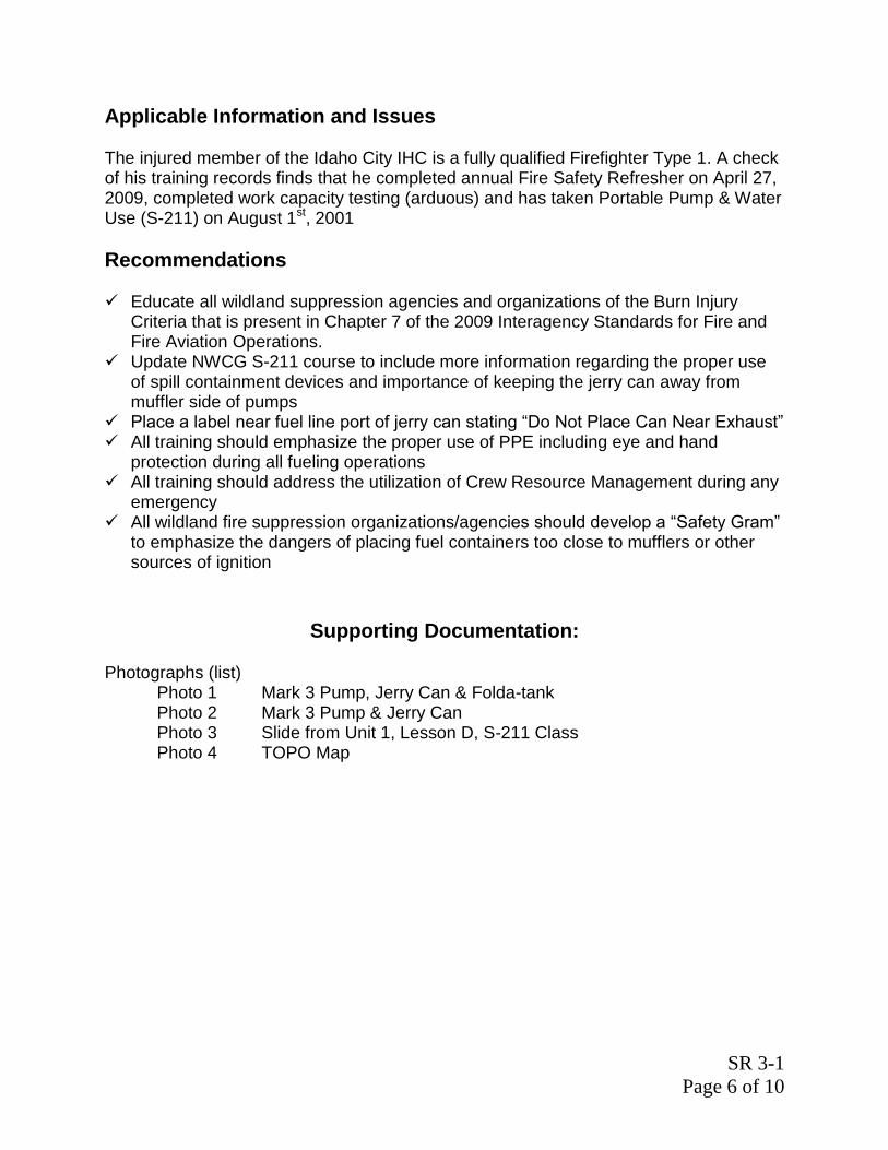
SR 3-1
Page 6 of 10
Applicable Information and Issues The injured member of the Idaho City IHC is a fully qualified Firefighter Type 1. A check of his training records finds that he completed annual Fire Safety Refresher on April 27, 2009, completed work capacity testing (arduous) and has taken Portable Pump & Water Use (S-211) on August 1st, 2001
Recommendations Educate all wildland suppression agencies and organizations of the Burn Injury
Criteria that is present in Chapter 7 of the 2009 Interagency Standards for Fire and Fire Aviation Operations.
Update NWCG S-211 course to include more information regarding the proper use of spill containment devices and importance of keeping the jerry can away from muffler side of pumps
Place a label near fuel line port of jerry can stating “Do Not Place Can Near Exhaust” All training should emphasize the proper use of PPE including eye and hand
protection during all fueling operations All training should address the utilization of Crew Resource Management during any
emergency All wildland fire suppression organizations/agencies should develop a “Safety Gram”
to emphasize the dangers of placing fuel containers too close to mufflers or other sources of ignition
Supporting Documentation: Photographs (list) Photo 1 Mark 3 Pump, Jerry Can & Folda-tank Photo 2 Mark 3 Pump & Jerry Can Photo 3 Slide from Unit 1, Lesson D, S-211 Class Photo 4 TOPO Map

SR 3-1
Page 7 of 10

SR 3-1
Page 8 of 10

SR 3-1
Page 9 of 10

SR 3-1
Page 10 of 10

SR 3-2
Page 1 of 2
Troubleshooting Portable Water Delivery Systems Symptoms and Remedies
Symptom: Engine does not start or starts momentarily and then stops.
Possible Cause Remedy
Fuel supply tank empty. Refill fuel tank.
Fuel supply valve closed. Open supply valve.
Air vent on fuel tank closed. Open air vent or unscrew cap.
Defective fuel supply hose. Replace.
Dirty fuel strainer screen. Clean or replace.
Leak in fuel supply system. Tighten or replace fittings.
Carburetor mountings loose. Tighten mountings.
Water or dirt in fuel system. Drain, and then flush thoroughly.
Too much oil in fuel mixture. Mix new batch of fuel.
Engine flooded. Dry the engine.
Air filter dirty. Clean or replace.
Spark plug fouled or defective. Clean or replace.
No spark. Cannot repair in field. Use flagging to identify
problem, and return the pump to warehouse.
Symptom: Engine runs irregularly or misfires.
Possible Cause Remedy
Defective fuel supply hose. Replace.
Dirty fuel strainer screen. Clean or replace.
Leak in fuel supply system. Tighten or replace fittings.
Carburetor mountings loose. Tighten mountings.
Water or dirt in fuel system. Drain, and then flush thoroughly.
Wrong gasoline in fuel mixture. Mix new batch of fuel.
Too much oil in fuel mixture. Mix new batch of fuel.
Air filter dirty. Clean or replace.
Spark plug fouled or defective. Clean or replace.
Wrong type spark plug. Use recommended plug.

SR 3-2
Page 2 of 2
Symptom: Engine backfires.
Possible Cause Remedy
Spark plug fouled or defective. Clean or replace.
Symptom: Engine does not idle properly.
Possible Cause Remedy
Carburetor mountings loose. Tighten mountings.
Too much oil in fuel mixture. Mix new batch of fuel.
Spark plug fouled or defective. Clean or replace.
Wrong type spark plug. Use recommended plug.
Symptom: Engine does not develop normal power, overheats, or both.
Possible Cause Remedy
Carburetor mounting loose. Tighten mountings.
Wrong gasoline in fuel mixture. Mix new batch of fuel.
Wrong oil in fuel mixture. Mix new batch of fuel.
Not enough oil in fuel mixture. Mix new batch of fuel.
Too much oil in fuel mixture. Mix new batch of fuel.
Air filter dirty. Replace.
Spark plug fouled or defective. Clean or replace.
Wrong type of spark plug. Use recommended plug.
Muffler blocked or dirty. Replace.
Symptom: Engine sounds like a four stroke engine.
Possible Cause Remedy
Too much oil in fuel mixture. Mix new batch of fuel.
Engine not warmed up properly. Allow longer warmup period.
Air filter dirty. Clean or replace.

4.1
Portable Pumps and Water Use, S-211
Unit 4 – System Design and Hydraulics
OBJECTIVES: Upon completion of this unit, students will be able to: 1. List one reason it is important for a pump and nozzle operator to have a
basic understanding of hydraulics. 2. Given scenarios, determine flow and pump discharge pressure, and select
appropriate pump(s). 3. Given scenarios, draw a schematic of the design of a water delivery system,
and troubleshoot the delivery system. 4. Given scenarios, determine whether parallel hose lay, series pumping, or
parallel pumping would be the best option.

4.2
4.3
I. INTRODUCTION
A water delivery system can be as simple as one pump, one hose, and one nozzle, or it can be a complex system of several pumps, several hoses, and several nozzles. If the goal of a water delivery system is to provide proper flow and pressure to meet the tactical objectives – how does the crew boss, squad boss, and/or pump operator determine: • What pumping configuration(s) will work?
• What hose lay design will work (i.e., hose diameter, hose length,
laterals)?
• What type of nozzle(s) to use?
In many situations, these decisions are made through trial and error, which is a time-consuming process that is not an efficient use of resources, time, and effort. Fireline personnel can reduce a lot of this guesswork by planning ahead and applying basic hydraulic concepts. Know ahead of time – before setting it up – if the system will work. A. Hydraulics is the science and engineering that deals with fluids at rest
and in motion. B. Why is having a basic understanding of hydraulics important?
1. To ensure proper amount of water and pressure is delivered to the nozzle(s).
2. To determine equipment needed, keep it working, and prevent
damage. 3. To design and troubleshoot the water delivery system. 4. To help ensure a safe work environment.
4.4
II. THREE-STEP PROCESS TO DETERMINE IF WATER DELIVERY SYSTEM WILL WORK
There is a three-step process to determine if a water delivery system will work. These steps help ensure that the pump is capable of providing required flow and pressure to the nozzle(s). Does this three-step process need to be used for every water delivery system encountered in the field? No, especially with simple delivery systems. But, when the delivery systems get to be more complex (e.g., more pumps, more laterals), going through the steps is critical. A. Step 1 – Determine Flow Rate
• Flow rate is the amount of water in gallons per minute (gpm) discharged through the hose lay.
• Note: The terms flow and discharge are used interchangeably.
Typically, “flow” is used when talking about the hose lay (water is flowing through the hose lay), and “discharge” is used when talking about the nozzle (water flow is being discharged out the nozzle).
• How to determine flow rate will be discussed in the next
section.
B. Step 2 – Calculate Pump Discharge Pressure
Pump Discharge Pressure (PDP) is the pressure in pounds per square inch (psi), required to deliver a specific pressure and flow at the nozzle. PDP is measured at the pump panel. How to determine PDP will be discussed in the next section.

4.5
C. Step 3 – Determine What Types of Pumps Are Capable of Providing Flow and PDP (Pump Performance)
In Unit 2 (Equipment), pump performance was defined as the flow (gpm) and pressure (psi) that the pump is capable of providing (refer to the chart, Portable Pump Performance – National Cache Pumps [HO 2-1]).
The three-step process will be explained in detail for the following situations: • Hose lays with no laterals
• Hose lays (with no laterals) that have different size hoses
• Hose lays with laterals
III. HOSE LAYS WITH NO LATERALS
This section will describe the three-step process for hose lays without laterals (simple hose lays). A. Step 1 – Determine Flow Rate
1. The type of nozzle(s) on the hose lay determines flow rate.
Note: Tactical objectives determine what type of nozzle is used. Nozzles have different flow rates, for example: • Twin tip nozzle with 3/16″ tip has a flow rate of 7 gpm at
50 psi.
• Adjustable barrel nozzle with 1″ tip has a flow rate of 20 gpm at 100 psi.

4.6
2. To find the flow rates for different nozzles, refer to the IRPG or use the nozzle discharge calculator. The nozzle’s manufacturer also provides flow rates.
• IRPG
The IRPG provides flow rates for commonly used nozzle types and sizes.
• Nozzle Discharge Calculator
Use the nozzle discharge calculator to determine flow rates for various types of nozzles. Note: This calculator is traditionally referred to as the “friction loss calculator”; however, it is really comprised of two different calculators: nozzle discharge calculator and friction loss calculator. – First, align the nozzle pressure with the arrow.
For example, you are using a 3/16″ tip, which is operated at 50 psi; align 50 psi with the arrow.
– Next, read the discharge (flow) above “NOZZLE BORE.”
For example, what is the flow from a 3/16″ tip (which has 50 psi)? Answer: 7 gpm
– Round answers.
Rounding and not rounding can lead to different answers, especially with long hose lays.
– Remember, this is not an exact science – the goal
is to get an estimate.
– Practice: What is the flow rate from a 3/8″ tip at 50 psi? _________

4.7
B. Step 2 – Calculate PDP
Use this formula to calculate PDP: NP ± HP + FL = PDP NP = Nozzle Pressure HP = Head Pressure FL = Friction Loss PDP = Pump Discharge Pressure 1. Nozzle Pressure (NP)
• Nozzle pressure is the pressure that the nozzle is designed to operate at most efficiently.
The unit for NP is psi.
• The type of nozzle that is on the hose lay determines the nozzle pressure.
The nozzle pressure in the formula will be either 50 psi or 100 psi, because the two commonly used nozzles in wildland fire are the twin tip nozzle (50 psi) and the adjustable barrel nozzle (100 psi). These nozzles are designed to operate most efficiently at 50 or 100 psi; however, they will operate at lower or higher pressures.
• The IRPG lists the nozzle pressure for each type of nozzle.
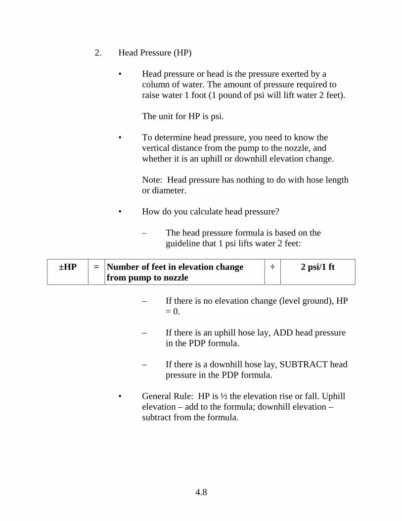
4.8
2. Head Pressure (HP)
• Head pressure or head is the pressure exerted by a column of water. The amount of pressure required to raise water 1 foot (1 pound of psi will lift water 2 feet).
The unit for HP is psi.
• To determine head pressure, you need to know the vertical distance from the pump to the nozzle, and whether it is an uphill or downhill elevation change.
Note: Head pressure has nothing to do with hose length or diameter.
• How do you calculate head pressure?
– The head pressure formula is based on the guideline that 1 psi lifts water 2 feet:
±HP = Number of feet in elevation change
from pump to nozzle ÷ 2 psi/1 ft
– If there is no elevation change (level ground), HP
= 0.
– If there is an uphill hose lay, ADD head pressure in the PDP formula.
– If there is a downhill hose lay, SUBTRACT head
pressure in the PDP formula.
• General Rule: HP is ½ the elevation rise or fall. Uphill elevation – add to the formula; downhill elevation – subtract from the formula.

4.9
• Practice:
– The nozzle is 250 feet (elevation change) uphill from the pump. What is the head pressure? _________________
– The nozzle is 100 feet (elevation change) downhill from the pump. What is the head pressure? __________________
– The nozzle is 250 feet (elevation change) downhill from the pump. What is the head pressure? __________________
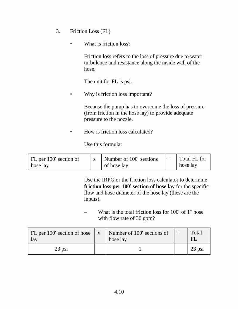
4.10
3. Friction Loss (FL)
• What is friction loss?
Friction loss refers to the loss of pressure due to water turbulence and resistance along the inside wall of the hose.
The unit for FL is psi.
• Why is friction loss important?
Because the pump has to overcome the loss of pressure (from friction in the hose lay) to provide adequate pressure to the nozzle.
• How is friction loss calculated?
Use this formula:
FL per 100′ section of hose lay
x Number of 100′ sections of hose lay
= Total FL for hose lay
Use the IRPG or the friction loss calculator to determine friction loss per 100′ section of hose lay for the specific flow and hose diameter of the hose lay (these are the inputs). – What is the total friction loss for 100′ of 1″ hose
with flow rate of 30 gpm?
FL per 100′ section of hose lay
x Number of 100′ sections of hose lay
= Total FL
23 psi 1 23 psi

4.11
• Practice
– In this practice, use the IRPG to find the FL per 100′ section of hose lay for the specified hose diameter and flow.
– What is the total FL for 300′ of 1½″ hose with
flow rate of 30 gpm?
FL per 100′ section of hose lay
x Number of 100′ sections of hose lay
= Total FL

4.12
• Use the friction loss calculator.
– There will be situations when the IRPG does not provide the friction loss information that is needed. In those situations, the friction loss calculator can be used to determine friction loss for specific hose diameter and flow.
– Become oriented to the friction loss calculator by
finding the flow (gpm), psi loss per 100 ft single line and size of hose. And then follow these steps:
First, align flow rate with the arrow. Next, read friction loss opposite hose size diameter. For example, if flow rate is 30 gpm, what is the friction loss in 3/4″ hose? What is the friction loss for 30 gpm (flow rate) through 1½″ hose?

4.13
– Practice
What is the total friction loss for 300′ of 1″ hose with flow rate of 30 gpm?
FL per 100′ section of hose lay
x Number of 100′ sections of hose lay
= Total FL
x =
What is total friction loss for 300′ of ¾″ hose @ 30 gpm?
FL per 100 feet section in hose lay
x Number of 100 feet sections in hose lay
= Total FL
x =

4.14
• Friction Loss Principles
This section discusses three friction loss principles. These principles help explain the relationship between friction loss and flow, hose diameter, and hose length. – Principle: When flow (gpm) decreases friction
loss decreases (when hose diameter is constant).
Practice: Flow rate is 40 gpm. What is friction loss in 1″ hose? ______________ Practice: Flow rate is 20 gpm. What is friction loss in 1″ hose? ______________

4.15
If flow increases, would friction loss increase or decrease? – Principle: When hose diameter increases, friction
loss decreases.
Practice: Flow rate is 30 gpm. What is the friction loss in 1″ hose? ______________ Practice: Flow rate is 30 gpm. What is the friction loss in 1½″ hose? ______________ Note: The 1″ hose has approximately 7 times the friction loss of 1½″ hose.

4.16
– Principle: Longer hose lengths have increased friction loss.
Practice: Flow rate is 20 gpm. What is friction loss in 100′ of 1″ hose? ___________________ Practice: Flow rate is 20 gpm. What is friction loss in 300′ of 1″ hose? _________________

4.17
4. Add the numbers together to determine Pump Discharge Pressure (PDP)
We have just discussed how to determine nozzle pressure, head pressure, and friction loss. Now it is time to put it all together and determine pump discharge pressure. Remember, PDP is the pressure required to deliver a specific pressure and flow at the nozzle. And, it is measured at the pump panel. Use this formula to calculate PDP: NP ± HP + FL = PDP NP = Nozzle Pressure HP = Head Pressure FL = Friction Loss PDP = Pump Discharge Pressure

4.18
We will use Scenario A to demonstrate how to calculate PDP. Scenario A: The hose lay has 500′ of 1½″ hose; one Forester nozzle with a 3/8″ tip attached. There is no elevation difference between the nozzle and pump.
Step 1: What is flow rate? Flow rate for 3/8″ tip = 30 gpm Step 2: What is PDP?
Nozzle Pressure (3/8″ tip)
= +50 psi
Head Pressure There is no elevation difference.
= 0 psi
Friction Loss (for 500′ of 1½″ hose @ 30 gpm) Math: 100′ of 1½″ hose @ 30 gpm = 3 psi 3 psi x 5 lengths of 100′ hose = 15 psi
= +15 psi
PDP = 65 psi Scenario A requires a flow of 30 gpm and pump discharge pressure at 65 psi. You have now learned how to complete Steps 1 and 2. Now it is time for the last step.
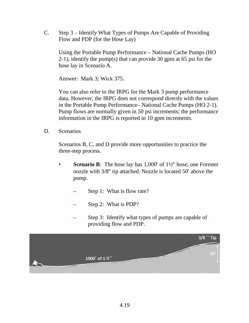
4.19
C. Step 3 – Identify What Types of Pumps Are Capable of Providing Flow and PDP (for the Hose Lay)
Using the Portable Pump Performance – National Cache Pumps (HO 2-1), identify the pump(s) that can provide 30 gpm at 65 psi for the hose lay in Scenario A. Answer: Mark 3; Wick 375. You can also refer to the IRPG for the Mark 3 pump performance data. However, the IRPG does not correspond directly with the values in the Portable Pump Performance– National Cache Pumps (HO 2-1). Pump flows are normally given in 50 psi increments; the performance information in the IRPG is reported in 10 gpm increments.
D. Scenarios
Scenarios B, C, and D provide more opportunities to practice the three-step process. • Scenario B: The hose lay has 1,000′ of 1½″ hose; one Forester
nozzle with 3/8″ tip attached. Nozzle is located 50′ above the pump.
– Step 1: What is flow rate?
– Step 2: What is PDP?
– Step 3: Identify what types of pumps are capable of
providing flow and PDP.

4.20
Step 1: Flow rate = 30 gpm Note: 3/8″ tip Step 2: Calculate PDP.
Nozzle Pressure (3/8″ tip)
=
Head Pressure (50′ ÷ 2 psi/1″) ADD head pressure due to uphill elevation.
=
Friction Loss (for 1000′ of 1½″ hose @ 30 gpm) Math: 100′ of 1½″ hose @ 30 gpm = 3 psi 3 psi x 10 lengths of 100′ hose = 30 psi
=
PDP = Step 3: Identify what types of pumps are capable of providing flow and PDP. Using the Portable Pump Performance – National Cache Pumps (HO 2-1), what pump(s) can provide the gpm and psi for this hose lay? If you have any questions or need clarification, ask the instructor for assistance. The scenarios will get more difficult, and understanding the basics is essential.

4.21
• Scenario C: The hose lay has 900′ of 1″ hose; one Forester nozzle with ¼″ tip attached. Nozzle is located 150′ above the pump.
– Step 1: What is flow rate?
– Step 2: What is PDP?
– Step 3: Identify what types of pumps are capable of
providing flow and PDP.
Step 1: Flow rate = 13 gpm Note: 1/4″ tip

4.22
Step 2: Calculate PDP.
Nozzle Pressure (for Forester nozzle with ¼″ tip)
=
Head Pressure (150′ ÷ 2 psi/1″) ADD head pressure due to uphill elevation.
=
Friction Loss (for 900′ of 1″ hose @ 13 gpm) Math: 100′ of 1″ hose @ 13 gpm = 4 psi 4 psi x 9 lengths of 100′ hose = 36 psi
=
PDP = Step 3: Identify what types of pumps are capable of providing flow and PDP. Using the Portable Pump Performance – National Cache Pumps (HO 2-1), what pump(s) can provide the gpm and psi for this hose lay?

4.23
• Scenario D: The hose lay has 1200′ of 1½″ hose; one 60 gpm adjustable barrel nozzle. Nozzle is located 180′ below the pump.
– Step 1: What is flow rate?
– Step 2: What is PDP?
– Step 3: Identify what types of pumps are capable of
providing flow and PDP.
Step 1: Flow rate (given) = 60 gpm Note: All prior scenarios had a twin tip nozzle; this is the first scenario with an adjustable barrel nozzle.
4.24
Step 2: Calculate PDP.
Nozzle Pressure (for adjustable barrel) The nozzle pressure is 100 psi because this scenario has an adjustable barrel nozzle.
=
Head Pressure (180′ ÷ 2 psi/1″) SUBTRACT head pressure due to downhill elevation change.
=
Friction Loss (for 1200′ of 1½″ hose @ 60 gpm) Math: 100′ of 1½″ hose @ 60 gpm = 13 psi 13 psi x 12 lengths of 100′ hose = 156 psi
=
PDP = Step 3: Identify what types of pumps are capable of providing flow and PDP. Using the Portable Pump Performance – National Cache Pumps (HO 2-1), what pump(s) can provide the gpm and psi for this hose lay? You have just gone through several scenarios on how to determine PDP for hose lays without laterals. Now, you will learn how to determine PDP for a hose lay that has different size hoses.
4.25
IV. HOSE LAY (NO LATERALS) WITH DIFFERENT SIZE HOSES A. Process Is Slightly Different
Determining flow rate and PDP for a hose lay with different size hoses is very similar to what you have already learned; the only difference is in how friction loss is calculated. Step 1: Flow Rate (same process) Step 2: PDP • NP (same process)
• HP (same process)
• Friction loss (different process)
Friction loss is calculated for each hose size and then added together to get total friction loss.
Step 3: Identify pump (same process) Scenario E will demonstrate the steps.

4.26
B. Scenario E
The hose lay has 500′ of 1½″ hose, which is reduced down to 100′ of 1″ hose. One Forester nozzle with 3/8″ tip attached. There is no elevation difference between the pump and the nozzle. • Step 1: What is flow rate?
• Step 2: What is PDP?
• Step 3: Identify what types of pumps are capable of providing
flow and PDP.
Step 1: Flow rate = 30 gpm Note: 3/8″ tip

4.27
Step 2: Calculate PDP.
Nozzle Pressure (for Forester nozzle with 3/8″ tip)
=
Head Pressure (no elevation change)
=
Friction Loss (for 100′ of 1″ hose @ 30 gpm)
=
Friction loss (for 500′ of 1½″ hose @ 30 gpm) Math: 100′ of 1½″ hose @ 30 gpm = 3 psi 3 psi x 5 lengths of 100′ hose = 15 psi
=
PDP = Step 3: Identify what types of pumps are capable of providing flow and PDP. Using the Portable Pump Performance – National Cache Pumps (HO 2-1), what pump(s) can provide the gpm and psi for this hose lay?
4.28
V. HOSE LAY WITH LATERALS
A. Process Requires More Steps
When a hose lay has laterals, how does the step-by-step process change? • Step 1: Flow rate (slightly different process)
– Calculate flow in all laterals to determine flow rate in
each section of the trunk.
• Step 2: PDP
– Nozzle pressure (same process)
– Head pressure (same process)
– Friction loss (slightly different process)
Calculate FL for only 1 lateral; the lateral that has the potential for the most friction loss. It could be the lateral with the highest flow or the lateral with the longest hose. Calculate FL for each section of the trunk.
• Step 3: Identify pumps (same process)
Scenarios F and G will illustrate how to calculate PDP for hose lays with laterals. In these scenarios, the term “trunk” refers to the hose that comes straight off the pump. “Laterals” refer to the hoses that are added to the trunk using a “hose line tee or wye valve” (lateral junction).
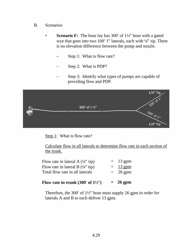
4.29
B. Scenarios
• Scenario F: The hose lay has 300′ of 1½″ hose with a gated wye that goes into two 100′ 1″ laterals, each with ¼″ tip. There is no elevation difference between the pump and nozzle.
– Step 1: What is flow rate?
– Step 2: What is PDP?
– Step 3: Identify what types of pumps are capable of
providing flow and PDP.
Step 1: What is flow rate? Calculate flow in all laterals to determine flow rate in each section of the trunk.
Flow rate in lateral A (¼″ tip) = 13 gpm Flow rate in lateral B (¼″ tip) = 13 gpm Total flow rate in all laterals = 26 gpm Flow rate in trunk (300′ of 1½″) = 26 gpm
Therefore, the 300′ of 1½″ hose must supply 26 gpm in order for laterals A and B to each deliver 13 gpm.

4.30
Step 2: Calculate PDP
Nozzle Pressure (for Forester nozzle with ¼″ tip) Note: Do not add nozzle pressures.
=
Head Pressure (no elevation change)
=
Friction Loss – Lateral A (for 100′ of 1″ @ 13 gpm) Note: Calculate friction loss for only 1 lateral. Choose the lateral that has the potential for the most friction loss; it could be the lateral with the highest flow or the lateral with the longest hose. And, make sure to use the gpm for the lateral chosen.
=
Friction Loss – Trunk (for 300′ of 1½″ @ 26 gpm) Math: 100′ of 1½″ hose @ 26 gpm = 2 psi 2 psi x 3 lengths of 100′ hose = 6 psi Note: Calculate the friction loss for each section of the trunk; in this scenario, there is only 1 trunk.
=
PDP =
Step 3: Identify what types of pumps are capable of providing flow and PDP. Using the Portable Pump Performance – National Cache Pumps (HO 2-1), what pump(s) can provide the gpm and psi for this hose lay?

4.31
• Scenario G: The hose lay has 700′ of 1½″ hose until the first lateral. Then there is another 100′ of 1½″ hose to the second lateral and another 100′ of 1½″ hose to the third lateral. All laterals have 100′ of 1″ hose and ¼″ tips. There is no elevation difference between the pump and nozzle.
– Step 1: What is flow rate?
– Step 2: What is PDP?
– Step 3: Identify what types of pumps are capable of
providing flow and PDP.
Step 1: What is flow rate? Calculate FLOW in all laterals to determine flow rate in each section of the trunk. Flow rate in lateral A (¼″ tip) = 13 gpm Flow rate in lateral B (¼″ tip) = 13 gpm Flow rate in lateral C (¼″ tip) = 13 gpm Total flow rate in all laterals = 39 gpm Calculate FLOW in each section of the trunk. Flow rate – trunk Z (100′ of 1½″ hose) = 13 gpm Flow rate – trunk Y (100′ of 1½″ hose) = 26 gpm Flow rate – trunk X (700′ of 1½″ hose) = 39 gpm
4.32
Step 2: Calculate PDP.
Nozzle Pressure (for Forester nozzle with for ¼″ tip)
Note: Do not add nozzle pressures.
=
Head Pressure (no elevation change)
=
Friction Loss – Lateral C (for 100′ of 1″ @ 13 gpm)
Note: Calculate friction loss for only 1 lateral. Choose the lateral that has the potential for the most friction loss; it could be the lateral with the highest flow or the lateral with the longest hose. And, make sure to use the gpm for the lateral chosen. In this scenario, all the laterals are the same flow, so it doesn’t matter which lateral is selected.
Friction Loss – Trunk Z (for 100′ of 1½″ hose @ 13 gpm)
=
Friction Loss – Trunk Y (for 100′ of 1½″ hose @ 26 gpm)
=
Friction Loss – Trunk X (for 700′ of 1½″ hose @ 39 gpm)
Math: 100′ of 1½″ hose @ 39 gpm = 5 psi 5 psi x 7 lengths of 100′ hose = 35 psi
=
Note: Calculate the friction loss for each section of the trunk. Start at the end of the hose lay and work back to the pump. Make sure to use the flow rate that is specific for each section of the trunk.
PDP =
Remember that rounding can impact answers.

4.33
Step 3: Identify what types of pumps are capable of providing flow and PDP. Using the Portable Pump Performance – National Cache Pumps (HO 2-1), what pump(s) can provide the gpm and psi for this hose lay?

4.34
VI. ADVANCED WATER DELIVERY SYSTEMS
There are going to be situations, such as significant elevation rise and/or long hose lay, when a simple water delivery system is NOT going to be able to provide the needed pressure and flow. In these cases, advanced delivery systems need to be considered. An example of such a situation is shown in Scenario H. Scenario H: The hose lay has 1200′ of 1½″ hose. One 60 gpm adjustable barrel nozzle. Nozzle is located 60 feet above the pump.
Step 1: Flow rate = 60 gpm (given)
4.35
Step 2: Calculate PDP.
Nozzle Pressure (60 gpm adjustable barrel nozzle)
=
Head Pressure (60 feet uphill rise)
=
Friction loss
=
PDP =
Step 3: Identify what types of pumps are capable of providing flow and PDP. Using the Portable Pump Performance – National Cache Pumps (HO 2-1), what pump(s) can provide the gpm and psi for this hose lay?
4.36
A. Parallel Hose Lay
A parallel hose lay is an example of how changing the hose lay can reduce friction loss, which then reduces pump discharge pressure. 1. Refer to Types of Hose Lays (HO 3-2) for a general description
and characteristics of parallel hose lay.
• What is the main advantage of a parallel hose lay?
• What is a general guideline to determine the friction loss for parallel hose lay?
2. Parallel hose lay and Scenario H. Will parallel hose lay work?
If the Scenario H design was changed to a parallel hose lay design, how would that impact flow and pump discharge pressure? Assume parallel hose lay decreases friction loss by approximately ¼.
Scenario H Scenario H and Parallel Hose Lay Step 1: Flow rate = 60 gpm 60 gpm Step 2: PDP Nozzle Pressure = +100 psi +100 psi Head Pressure = +30 psi +30 psi Friction Loss = +156 psi +39 psi*
PDP 286 psi 169 psi *The friction loss of 39 psi was determined by using the general rule that a parallel hose lay decreases friction loss by approximately ¼ (156 psi ÷ 4 = 39 psi). This is an estimate.
Answer: Flow does not change. Friction loss decreases, which resulted in PDP decreasing from 286 psi to 169 psi. The Mark 3 and the Wick 375 can provide 60 gpm at 169 psi for this hose lay (refer to the Portable Pump Performance – National Cache Pumps [HO 2-1])

4.37
B. Series Pumping
1. Refer to Portable Pump Configurations (HO 3-1) for a general description and characteristics of series pumping.
• Series pumping is a way to increase pump performance
(by using more than one pump), which will increase pressure.
• When using series pumping, the pressures of both pumps
are combined, but flow stays the same.
For example, one Mark 3 pump can provide 60 gpm at 170 psi. If another Mark 3 pump is added in series, the combination will provide 60 gpm at 340 psi.
• Series pumping is often used to overcome significant elevation rise, long hose lay, or whenever more pressure is needed.
• What happens if the first pump fails?
2. Series pumping and Scenario H. Will series pumping work?
• Will series pumping be able to provide the flow (60 gpm) and PDP (286 psi) that Scenario H required?
Scenario H Series Pumping and Scenario H Step 1: Flow rate = 60 gpm 60 gpm Step 2: PDP Nozzle Pressure = +100 psi +100 psi Head Pressure = +30 psi +30 psi Friction Loss = +156 psi +156 psi*
PDP 286 psi 286 psi

4.38
Answer: Yes, the Mark 3 can produce 60 gpm at 170 psi. If two Mark 3 pumps are set up as series pumping, they can provide 60 gpm at 340 psi. Since this hose lay requires 60 gpm at 286 psi – the two Mark 3 pumps (set up as series pumping) will work. This is also true for the Wick 375 pump. When pumps are used in series, pressures from each pump are combined (for example, 170 psi + 170 psi = 340 psi) with no change in flow.
C. Parallel Pumping
1. Refer to Portable Pump Configurations (HO 3-1) for a general description and characteristics of parallel pumping.
• Parallel pumping is a way to increase pump performance
(by using more than one pump), which increases flow, but not the pressure.
General rule is that it doubles the flow. When pumps are used in parallel, flow from each pump is added together with no change in pressure.
• Describe a field situation when parallel pumping would be a good option.
2. Parallel pumping and Scenario H. Will parallel pumping work?
• Will parallel pumping be able to provide the flow (60 gpm) and PDP (286 psi) that Scenario H required?
Scenario H Parallel Pumping Step 1: Flow rate = 60 gpm 60 gpm Step 2: PDP Nozzle Pressure = +100 psi +100 psi Head Pressure = +30 psi +30 psi Friction Loss = +156 psi +156 psi*
PDP 286 psi 286 psi

4.39
Answer: Yes. The Mark 3 can produce 30 gpm at 285 psi. If two Mark 3 pumps are set up for parallel pumping, then together they can provide 60 gpm at 286 psi. This is also true for the Wick 375 pump.
D. Review
VII. TROUBLESHOOTING THE DELIVERY SYSTEM FROM A HYDRAULIC PERSPECTIVE
The key to troubleshooting from a hydraulic perspective is to understand the relationships among all the different components in the system. This takes time and a lot of field experience. Troubleshooting often starts with trying to determine what the problem is and then figuring out what equipment (e.g., pumps, hose, appliances) is available to fix it. For example, if the problem is too much friction loss, using a larger diameter hose (if there is one available) would solve the problem, but there isn’t one available; another option is to use a parallel hose lay, if there is enough hose for that option. This section introduces troubleshooting from a hydraulic perspective; using pump discharge pressure and pump capability as the starting point. • Pump discharge pressure
Look at each of the components in the pump discharge pressure (PDP) formula to determine what may be causing the problem and to identify possible solutions: – Nozzle pressure
Change the type of nozzle, tip size, or both, to reduce pressure.
– Head pressure
Move the pump to a different location (to reduce head pressure); but this often isn’t an option.

4.40
– Friction loss
There are several options for reducing friction loss, such as increase hose diameter, shorten hose length, use a parallel hose lay, and/or reduce flow.
• Pump capability – How can pump capability be changed to meet the flow and PDP requirements?
– Use a pump that has higher performance capabilities – pressure
and flow.
– Use a series pumping system to increase pressure.
– Use a parallel pumping system to increase flow.
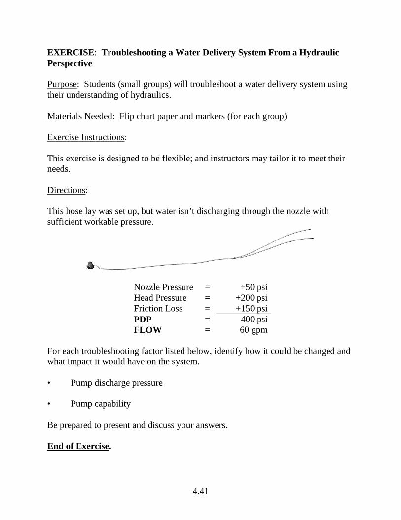
4.41
EXERCISE: Troubleshooting a Water Delivery System From a Hydraulic Perspective Purpose: Students (small groups) will troubleshoot a water delivery system using their understanding of hydraulics. Materials Needed: Flip chart paper and markers (for each group) Exercise Instructions: This exercise is designed to be flexible; and instructors may tailor it to meet their needs. Directions: This hose lay was set up, but water isn’t discharging through the nozzle with sufficient workable pressure.
Nozzle Pressure = +50 psi Head Pressure = +200 psi Friction Loss = +150 psi PDP = 400 psi
FLOW = 60 gpm For each troubleshooting factor listed below, identify how it could be changed and what impact it would have on the system. • Pump discharge pressure • Pump capability Be prepared to present and discuss your answers. End of Exercise.

4.42
VIII. DESIGNING A WATER DELIVERY SYSTEM USING HYDRAULIC CONCEPTS
In Unit 3 (Responsibilities), you learned that simple water delivery systems can be designed using a mental image, but more complicated systems should be designed on paper – to ensure they are hydraulically feasible. The delivery system design should include the following: • Portable pump configuration (including types of pumps)
• Hose lay design (trunks and laterals) including hose diameter and
length
• Nozzle type, tip size, or both
• Hydraulic calculations
– Flow (gpm)
– Pump discharge pressure (nozzle pressure, head pressure, friction loss)
This next exercise will give you practice in designing a delivery system that is hydraulically feasible.

4.43
EXERCISE: How to Design a Hydraulically Sound Water Delivery System Purpose: Students (small groups) will develop a schematic of a water delivery system and determine flow, PDP, and nozzle pressure of system. Then they will present their design to the large group. Materials Needed: Flip chart paper and markers (for each group) Directions: Your squad is mopping up a ½-acre spot fire burning in heavy slash. There is a 200-foot elevation change from the pump site (river) to the fire and the distance is 2,000 feet. The following equipment is available: • 2 Mark 3 pumps • 2 MK 26 pumps • 2500′ of 1½″ hose • 500′ of 1″ hose • 3 Forester nozzles with 3/16″ tip • 3 adjustable barrel nozzles (1″) • Assorted appliances and adapters Question 1: On the flip chart paper, draw a schematic (design) that is hydraulically feasible – the schematic needs to include the pump configuration, hose lay design, and nozzle types. Question 2: Determine pump discharge pressure (nozzle pressure, head pressure and friction loss), and write it on the schematic. Be prepared to present your answers to the large group. There are many solutions. End of Exercise.
4.44
IX. REVIEW
Question 1. Why is it important to understand hydraulic principles? Question 2. The hose lay has 500′ of 1½″ hose, and one Forester nozzle with a 3/8″ tip is attached. The nozzle is 30′ above the pump. a) What is flow?
b) What is PDP?
c) Identify pumps capable of providing flow and PDP.

4.45
Question 3. What is the definition of pump discharge pressure (PDP)? Where is pump discharge pressure measured? Question 4. When the nozzle is located uphill from the pump, do you subtract or add head pressure in the PDP formula? Question 5. When hose diameter increases, does friction loss increase or decrease? Question 6. When flow (gpm) decreases, does friction loss increase or decrease? Question 7. Do longer hose lengths have more or less friction loss than shorter hose lengths (of same diameter)?
4.46
Question 8. If there is significant elevation rise from the pump to the nozzle and one pump cannot provide the pressure that is needed, which multiple pump system would most likely solve the problem – series pumping or parallel pumping? Question 9. You are filling a drop tank, and it is going slow. You want to increase the flow to speed it up. What pump configuration would you use – series pumping or parallel pumping? Question 10. What impact do parallel lines have on friction loss – increase friction loss or decrease friction loss? Question 11. Friction loss needs to be reduced. What options should be considered?
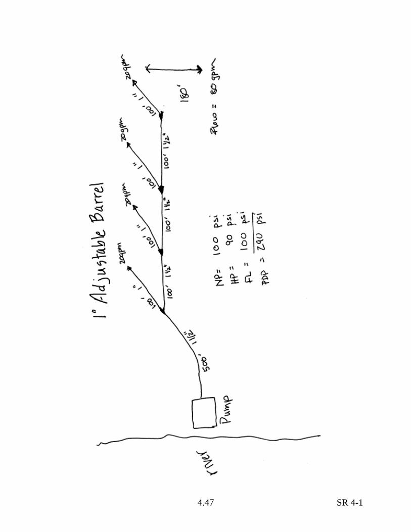
4.47 SR 4-1

4.48

5.1
Portable Pumps and Water Use, S-211
Unit 5 – Field Exercise
OBJECTIVES: Upon completion of this unit, students will be able to: 1. Participate in portable water delivery system set up, operation,
troubleshooting, and shut down. 2. Demonstrate appropriate risk management activities, such as wearing PPE
(including ear and eye protection as appropriate) and fuel handling procedures.

5.2
5.3
EXERCISE: Field Exercise Purpose: To provide experience with participating in setup, operation, troubleshooting, and shutdown of a portable water delivery system and demonstrating appropriate risk management activities. Students will be evaluated by instructors during the field exercise (30 points). Exercise Instructions: 1. A general overview of the field exercise will be provided. This overview
addresses:
• Schedule and logistics
• What students should bring – wear full PPE, IRPG, Student Workbook
• Objectives:
– Demonstrate appropriate risk management activities, such as
wearing PPE (including ear and eye protection as appropriate).
– Participate in portable water delivery system setup, operation, troubleshooting, and shutdown.
2. Evaluation method and criteria, and total points for the field exercise. 3. Small groups will be established and directions on where to go. 4. Demonstration and practice of proper procedures. 5. When exercise is completed, instructors may provide an After Action
Review (AAR) before evaluation. 6. Instructors evaluate students on Field Exercise Final Exam. Instructors will
determine total score on final exams (Classroom Final Exam plus Field Exercise Final Exam).
End of Exercise.

5.4