Embed Size (px)
Citation preview

OWNER’S MANUAL & OPERATING INSTRUCTIONS
12039 Smith Ave.Santa Fe Springs CA 90670
USA / 1-877-338-0999www.championpowerequipment.com
4000 Starting Watts/3500 Running Watts
PORTABLE GENERATOR
SAVE THESE INSTRUCTIONS Important Safety Instructions are included in this manual.
MADE IN CHINAREV 46539-20160302
Wireless Remote, Electric Start
46539MODEL NUMBER

*We are always working to improve our products. Therefore, the enclosed product may differ slightly from the image on the cover.
Have questions or need assistance?Do not return this product to the store!
WE ARE HERE TO HELP!Visit our website:
www.championpowerequipment.comfor more info:
• Product Info & Updates• Frequently Asked Questions
• Tech Bulletins• Product Registration
– or –
Call our Customer Care Team Toll-Free at:
1-877-338-0999
AN IMPORTANT MESSAGE ABOUT TEMPERATURE:Your Champion Power Equipment product is designed and rated for continuous operation at ambient temperatures up to 40°C (104°F). When your product is needed your product may be operated at temperatures ranging from -15°C (5°F) to 50°C (122°F) for short periods. If the product is exposed to temperatures outside this range during storage, it should be brought back within this range before operation. In any event, the product must always be operated outdoors, in a well-ventilated area and away from doors, windows and other vents.
For residents of California:WARNING: This product contains chemicals known to the State of California to cause cancer or birth defects
and other reproductive harm.
WARNING: The engine exhaust from this product contains chemicals known to the State of California to cause cancer and birth defects and other reproductive harm.
46539
Wireless Remote, Electric Start
PORTABLE GENERATOR4000 Starting Watts/3500 Running Watts
TABLE OF CONTENTSIntroduction . . . . . . . . . . . . . . . . . . . . . . . . . . . . . 1
Introduction . . . . . . . . . . . . . . . . . . . . . . . . . . . 1Portable Power Generator . . . . . . . . . . . . . . . . . . 1Accessories . . . . . . . . . . . . . . . . . . . . . . . . . . . 1This Booklet . . . . . . . . . . . . . . . . . . . . . . . . . . . 1
Manual Conventions. . . . . . . . . . . . . . . . . . . . . . . . 2Safety Rules . . . . . . . . . . . . . . . . . . . . . . . . . . . . . 3Controls and Features . . . . . . . . . . . . . . . . . . . . . . 5
Generator . . . . . . . . . . . . . . . . . . . . . . . . . . . . . 5Power Panel . . . . . . . . . . . . . . . . . . . . . . . . . . . 6Wireless Remote Control . . . . . . . . . . . . . . . . . . 7
Remote Control Power Consumption . . . . . . . . 7Power Panel Load Management . . . . . . . . . . . 7
Parts Included . . . . . . . . . . . . . . . . . . . . . . . . . 8Wheel Kit . . . . . . . . . . . . . . . . . . . . . . . . . . 8Other . . . . . . . . . . . . . . . . . . . . . . . . . . . . . 8
Assembly . . . . . . . . . . . . . . . . . . . . . . . . . . . . . . . 9Remove the Generator from the Shipping Carton . . 9Install the Wheel Kit . . . . . . . . . . . . . . . . . . . . . 9Install the Support Leg . . . . . . . . . . . . . . . . . . . 9Install the Handles . . . . . . . . . . . . . . . . . . . . . . 9Connect the Battery . . . . . . . . . . . . . . . . . . . . . 9Add Engine Oil . . . . . . . . . . . . . . . . . . . . . . . . 10Add Fuel . . . . . . . . . . . . . . . . . . . . . . . . . . . . 11Grounding . . . . . . . . . . . . . . . . . . . . . . . . . . . 11
Operation . . . . . . . . . . . . . . . . . . . . . . . . . . . . . . 12Generator Location . . . . . . . . . . . . . . . . . . . . . 12Grounding . . . . . . . . . . . . . . . . . . . . . . . . . . . 12Surge Protection . . . . . . . . . . . . . . . . . . . . . . . 12Wireless Remote and Electric Start . . . . . . . . . . 13Recoil Start . . . . . . . . . . . . . . . . . . . . . . . . . . 13Connecting Electrical Loads . . . . . . . . . . . . . . . 14Stopping the Engine . . . . . . . . . . . . . . . . . . . . 14Do Not Overload Generator . . . . . . . . . . . . . . . . 15
Capacity . . . . . . . . . . . . . . . . . . . . . . . . . . 15Power Management . . . . . . . . . . . . . . . . . . . 15
Operation at High Altitude . . . . . . . . . . . . . . . . 15
Maintenance and Storage . . . . . . . . . . . . . . . . . . . 16Engine Maintenance . . . . . . . . . . . . . . . . . . . . 16
Oil . . . . . . . . . . . . . . . . . . . . . . . . . . . . . . 16Spark Plugs . . . . . . . . . . . . . . . . . . . . . . . . 16Air Filter . . . . . . . . . . . . . . . . . . . . . . . . . . 16Spark Arrester . . . . . . . . . . . . . . . . . . . . . . 17Cleaning . . . . . . . . . . . . . . . . . . . . . . . . . . 17Adjustments . . . . . . . . . . . . . . . . . . . . . . . . 17Maintenance Schedule . . . . . . . . . . . . . . . . 17
Generator Maintenance . . . . . . . . . . . . . . . . . . 17Storage . . . . . . . . . . . . . . . . . . . . . . . . . . . . . 18
Generator Storage . . . . . . . . . . . . . . . . . . . . 18Battery . . . . . . . . . . . . . . . . . . . . . . . . . . . 18Charge the Battery . . . . . . . . . . . . . . . . . . . 18Disconnect the Battery . . . . . . . . . . . . . . . . 18Remote Control Battery . . . . . . . . . . . . . . . . 18
Specifications . . . . . . . . . . . . . . . . . . . . . . . . . . . 19Engine Specifications . . . . . . . . . . . . . . . . . . . 19Generator Specifications . . . . . . . . . . . . . . . . . 19Fuel . . . . . . . . . . . . . . . . . . . . . . . . . . . . . . . 19Oil . . . . . . . . . . . . . . . . . . . . . . . . . . . . . . . . 19Spark Plugs . . . . . . . . . . . . . . . . . . . . . . . . . . 19Maintenance Valve Clearance . . . . . . . . . . . . . . 19FCC Statement for Remote Control Device . . . . . 19Wiring Diagram . . . . . . . . . . . . . . . . . . . . . . . . 20Parts Diagram . . . . . . . . . . . . . . . . . . . . . . . . 21Parts List . . . . . . . . . . . . . . . . . . . . . . . . . . . . 22Engine Parts Diagram . . . . . . . . . . . . . . . . . . . 23Engine Parts List . . . . . . . . . . . . . . . . . . . . . . 24
Troubleshooting. . . . . . . . . . . . . . . . . . . . . . . . . . 25
1
ENGLISH 46539
IntroductionCongratulations on your purchase of a Champion Power Equipment generator. CPE designs and builds generators to strict specifications. With proper use and maintenance, this generator will bring years of satisfying service.
Portable Power GeneratorThis unit is a gasoline engine driven, alternating current (AC) generator. It is designed to supply electrical power for lighting, appliances, tools and similar equipment.
Record the model and serial numbers as well as date and place of purchase for future reference. Have this information available when ordering parts and when making technical or warranty inquiries.
AccessoriesChampion Power Equipment manufactures and sells accessories designed to help you get the most from your purchase. To find out more about our covers and power cables, please visit our web site at: www.championpowerequipment.com
This BookletEvery effort has been made to ensure the accuracy and completeness of the information in this manual. We reserve the right to change, alter and/or improve the product and this document at any time without prior notice.
Champion Power Equipment Support
Model Number
Serial Number
Date of Purchase
Purchase Location
1-877-338-0999
46539
For Oil Type see ‘Add Engine Oil‘ section. For Fuel Type see ‘Add Fuel‘ section.
INTRODUCTION
2
46539 ENGLISH
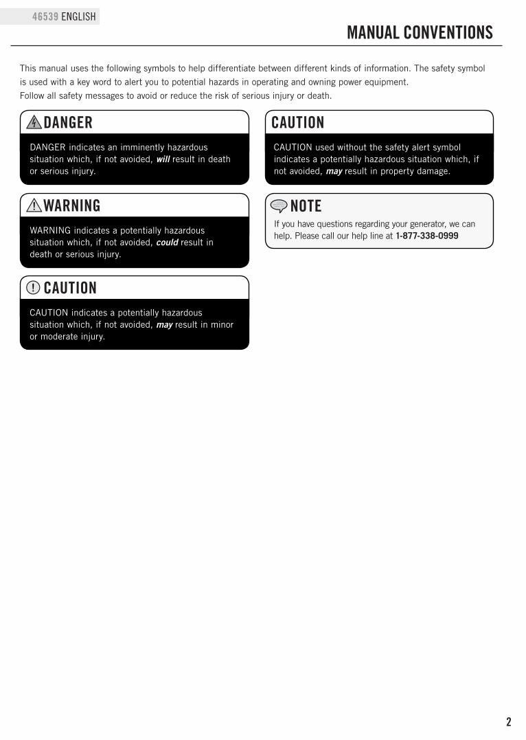
MANUAL CONVENTIONS
This manual uses the following symbols to help differentiate between different kinds of information. The safety symbol is used with a key word to alert you to potential hazards in operating and owning power equipment.Follow all safety messages to avoid or reduce the risk of serious injury or death.
CAUTION indicates a potentially hazardous situation which, if not avoided, may result in minor or moderate injury.
CAUTION
CAUTION used without the safety alert symbol indicates a potentially hazardous situation which, if not avoided, may result in property damage.
CAUTIONDANGER indicates an imminently hazardous situation which, if not avoided, will result in death or serious injury.
DANGER
WARNING indicates a potentially hazardous situation which, if not avoided, could result in death or serious injury.
WARNINGIf you have questions regarding your generator, we can help. Please call our help line at 1-877-338-0999
NOTE
3
ENGLISH 46539
SAFETY RULES
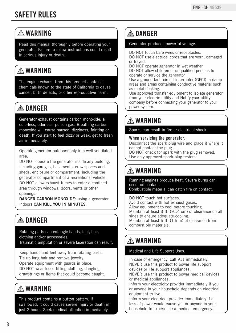
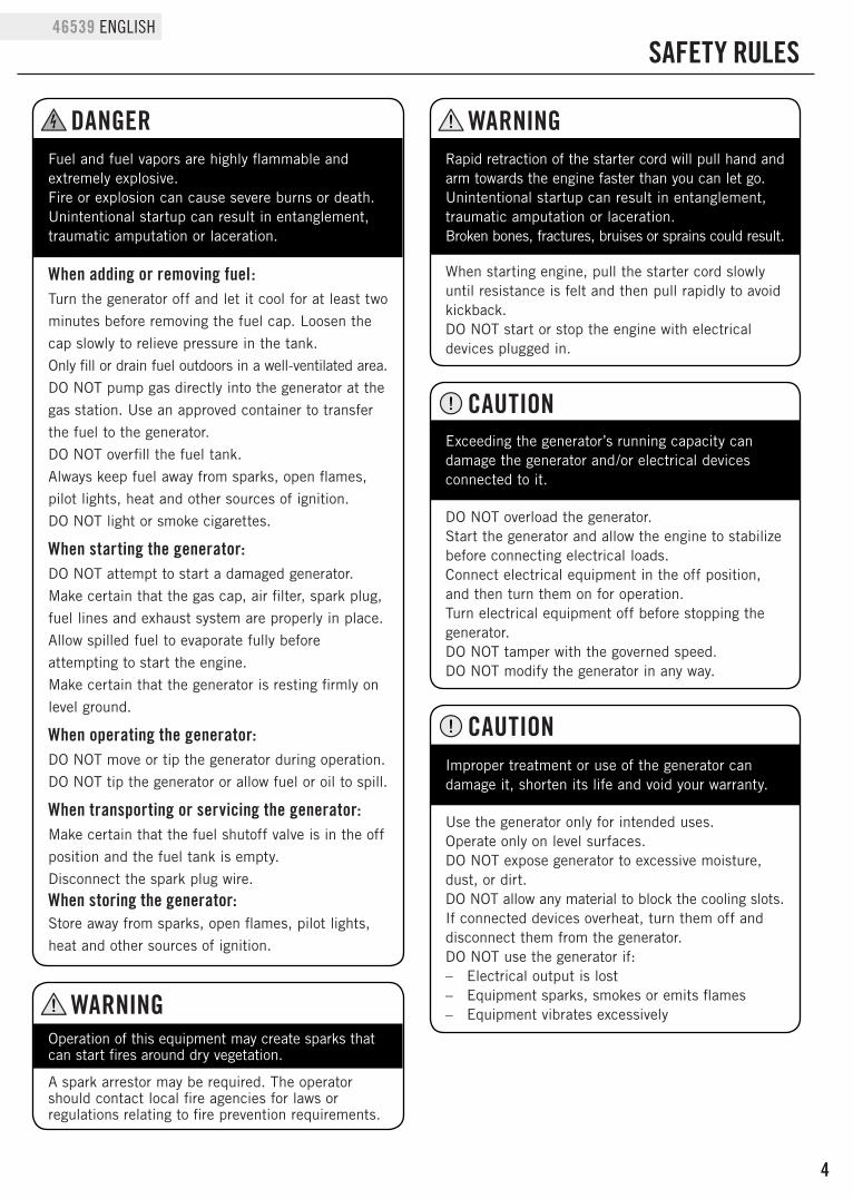
Generator exhaust contains carbon monoxide, a colorless, odorless, poison gas. Breathing carbon monoxide will cause nausea, dizziness, fainting or death. If you start to feel dizzy or weak, get to fresh air immediately.
Operate generator outdoors only in a well ventilated area.DO NOT operate the generator inside any building, including garages, basements, crawlspaces and sheds, enclosure or compartment, including the generator compartment of a recreational vehicle.DO NOT allow exhaust fumes to enter a confined area through windows, doors, vents or other openings.DANGER CARBON MONOXIDE: using a generator indoors CAN KILL YOU IN MINUTES.
DANGER
Rotating parts can entangle hands, feet, hair, clothing and/or accessories. Traumatic amputation or severe laceration can result.
Keep hands and feet away from rotating parts.Tie up long hair and remove jewelry.Operate equipment with guards in place.DO NOT wear loose-fitting clothing, dangling drawstrings or items that could become caught.
DANGER
Generator produces powerful voltage.
DO NOT touch bare wires or receptacles.DO NOT use electrical cords that are worn, damaged or frayed.DO NOT operate generator in wet weather.DO NOT allow children or unqualified persons to operate or service the generatorUse a ground fault circuit interrupter (GFCI) in damp areas and areas containing conductive material such as metal decking.Use approved transfer equipment to isolate generator from your electric utility and Notify your utility company before connecting your generator to your power system.
DANGER
Sparks can result in fire or electrical shock.
When servicing the generator:Disconnect the spark plug wire and place it where it cannot contact the plug.DO NOT check for spark with the plug removed.Use only approved spark plug testers.
WARNING
Running engines produce heat. Severe burns can occur on contact. Combustible material can catch fire on contact.
DO NOT touch hot surfaces.Avoid contact with hot exhaust gases.Allow equipment to cool before touching.Maintain at least 3 ft. (91.4 cm) of clearance on all sides to ensure adequate cooling.Maintain at least 5 ft. (1.5 m) of clearance from combustible materials.
WARNING
Medical and Life Support Uses.
In case of emergency, call 911 immediately.NEVER use this product to power life support devices or life support appliances.NEVER use this product to power medical devices or medical appliances.Inform your electricity provider immediately if you or anyone in your household depends on electrical equipment to live.Inform your electrical provider immediately if a loss of power would cause you or anyone in your household to experience a medical emergency.
WARNING
The engine exhaust from this product contains chemicals known to the state of California to cause cancer, birth defects, or other reproductive harm.
WARNING
Read this manual thoroughly before operating your generator. Failure to follow instructions could result in serious injury or death.
WARNING
This product contains a button battery. If swallowed, it could cause severe injury or death in just 2 hours. Seek medical attention immediately.
WARNING
4
46539 ENGLISH
SAFETY RULES
Improper treatment or use of the generator can damage it, shorten its life and void your warranty.
Use the generator only for intended uses.Operate only on level surfaces.DO NOT expose generator to excessive moisture, dust, or dirt.DO NOT allow any material to block the cooling slots.If connected devices overheat, turn them off and disconnect them from the generator.DO NOT use the generator if: – Electrical output is lost – Equipment sparks, smokes or emits flames – Equipment vibrates excessively
CAUTION
Rapid retraction of the starter cord will pull hand and arm towards the engine faster than you can let go. Unintentional startup can result in entanglement, traumatic amputation or laceration. Broken bones, fractures, bruises or sprains could result.
When starting engine, pull the starter cord slowly until resistance is felt and then pull rapidly to avoid kickback.DO NOT start or stop the engine with electrical devices plugged in.
WARNING
Exceeding the generator’s running capacity can damage the generator and/or electrical devices connected to it.
DO NOT overload the generator.Start the generator and allow the engine to stabilize before connecting electrical loads.Connect electrical equipment in the off position, and then turn them on for operation.Turn electrical equipment off before stopping the generator.DO NOT tamper with the governed speed. DO NOT modify the generator in any way.
CAUTION
Operation of this equipment may create sparks that can start fires around dry vegetation.
A spark arrestor may be required. The operator should contact local fire agencies for laws or regulations relating to fire prevention requirements.
WARNING
Fuel and fuel vapors are highly flammable and extremely explosive. Fire or explosion can cause severe burns or death. Unintentional startup can result in entanglement, traumatic amputation or laceration.
When adding or removing fuel:Turn the generator off and let it cool for at least two minutes before removing the fuel cap. Loosen the cap slowly to relieve pressure in the tank.Only fill or drain fuel outdoors in a well-ventilated area.DO NOT pump gas directly into the generator at the gas station. Use an approved container to transfer the fuel to the generator.DO NOT overfill the fuel tank.Always keep fuel away from sparks, open flames, pilot lights, heat and other sources of ignition.DO NOT light or smoke cigarettes.
When starting the generator:DO NOT attempt to start a damaged generator. Make certain that the gas cap, air filter, spark plug, fuel lines and exhaust system are properly in place.Allow spilled fuel to evaporate fully before attempting to start the engine.Make certain that the generator is resting firmly on level ground.
When operating the generator:DO NOT move or tip the generator during operation.DO NOT tip the generator or allow fuel or oil to spill.
When transporting or servicing the generator:Make certain that the fuel shutoff valve is in the off position and the fuel tank is empty.Disconnect the spark plug wire.When storing the generator:Store away from sparks, open flames, pilot lights, heat and other sources of ignition.
DANGER
5
ENGLISH 46539
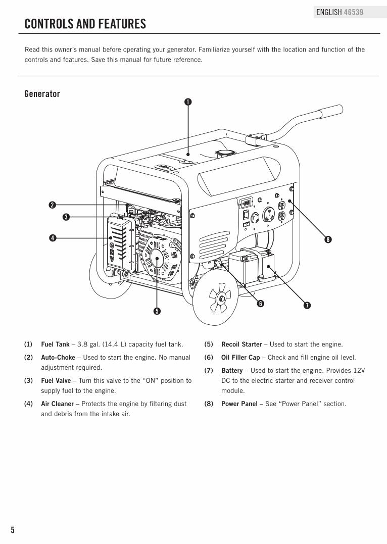
Read this owner’s manual before operating your generator. Familiarize yourself with the location and function of the controls and features. Save this manual for future reference.
(1) Fuel Tank – 3.8 gal. (14.4 L) capacity fuel tank.
(2) Auto-Choke – Used to start the engine. No manual adjustment required.
(3) Fuel Valve – Turn this valve to the “ON” position to supply fuel to the engine.
(4) Air Cleaner – Protects the engine by filtering dust and debris from the intake air.
(5) Recoil Starter – Used to start the engine.
(6) Oil Filler Cap – Check and fill engine oil level.
(7) Battery – Used to start the engine. Provides 12V DC to the electric starter and receiver control module.
(8) Power Panel – See “Power Panel” section.
1
5
3
2
4
76
8
Generator
CONTROLS AND FEATURES
6
46539 ENGLISH
Power Panel
1
5 6 7 8
3
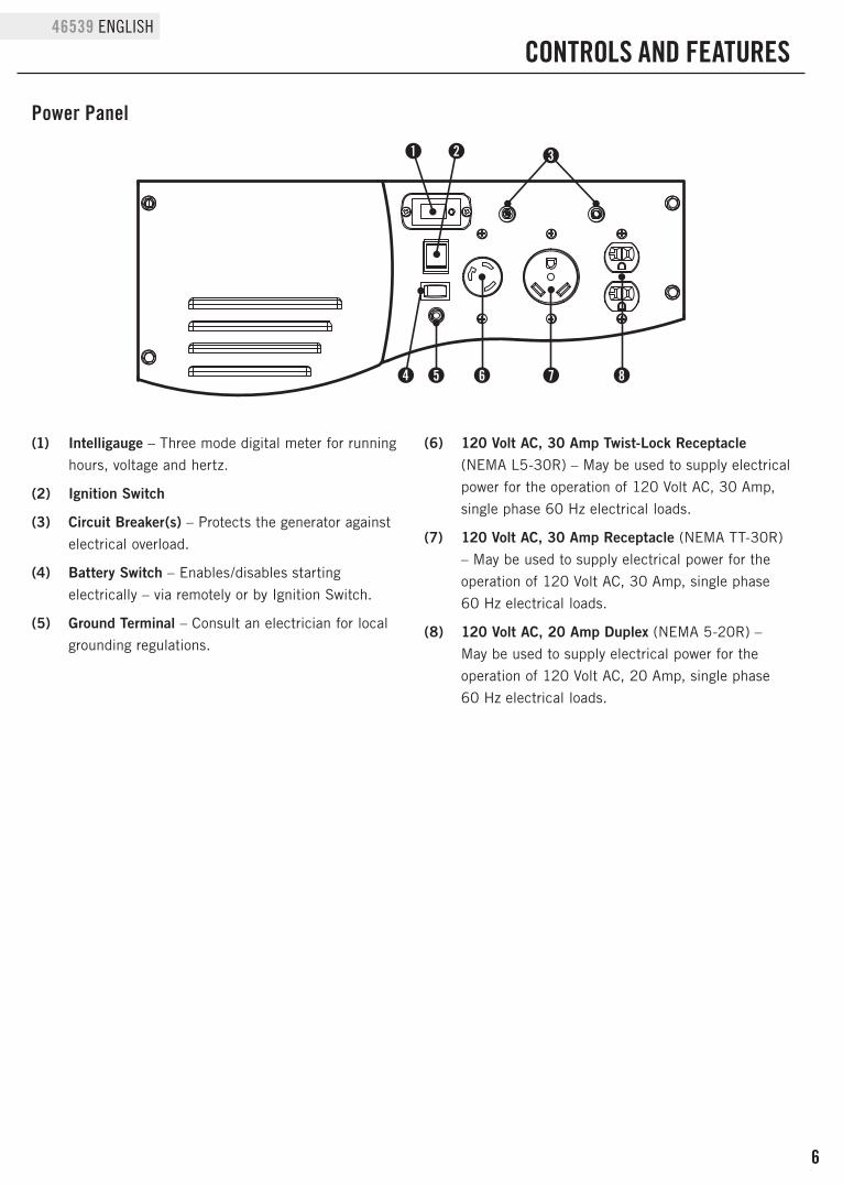
(1) Intelligauge – Three mode digital meter for running hours, voltage and hertz.
(2) Ignition Switch
(3) Circuit Breaker(s) – Protects the generator against electrical overload.
(4) Battery Switch – Enables/disables starting electrically – via remotely or by Ignition Switch.
(5) Ground Terminal – Consult an electrician for local grounding regulations.
(6) 120 Volt AC, 30 Amp Twist-Lock Receptacle (NEMA L5-30R) – May be used to supply electrical power for the operation of 120 Volt AC, 30 Amp, single phase 60 Hz electrical loads.
(7) 120 Volt AC, 30 Amp Receptacle (NEMA TT-30R) – May be used to supply electrical power for the operation of 120 Volt AC, 30 Amp, single phase 60 Hz electrical loads.
(8) 120 Volt AC, 20 Amp Duplex (NEMA 5-20R) – May be used to supply electrical power for the operation of 120 Volt AC, 20 Amp, single phase 60 Hz electrical loads.
2
CONTROLS AND FEATURES
4
7
ENGLISH 46539
CONTROLS AND FEATURES
Wireless Remote ControlThis generator is equipped with a wireless remote control system for starting and stopping. The system consists of (4) main components:1. Receiver Control Module (RCM)2. Wireless Remote3. Battery Switch4. Ignition SwitchThe Remote Control functions are enabled when:1. The Ignition Switch is in the “ON” position, AND2. The Battery Switch is in the “ON” position.The Remote Control functions are disabled if either of the above conditions is not met.To start the generator by Remote Control, press the “START” button on the Remote one time. The engine will attempt to start (6) times. The RCM controls the Auto Choke during each attempt to start. If the generator does not start, call Champion Customer Care team for assistance at 1-877-338-0999.To stop the generator by Remote Control, press the “STOP” button on the Remote one time.
Remote Control Power ConsumptionWhile the Ignition Switch is in the “ON: position, the RCM is active and waiting for a remote signal. This function requires electrical current from the battery. If the Ignition Switch is left in the “ON” position for extended periods (several weeks), the battery can be completely drained. Moving the Ignition Switch to the “OFF” position disables the Remote functions, but the RCM still consumes approximately 2 mA from the battery.To prevent battery drain, press the Battery Switch to the “OFF” position. This disconnects power to the RCM so there is no current draw on the battery.
Power Panel Load ManagementWhen the generator initially starts by the Remote, no voltage is supplied to the Power Panel for approximately 15 seconds. This allows the engine to reach full speed before electrical loads are applied to the generator. When the generator is stopped by the Remote, the voltage to the Power Panel is immediately turned off. Then the engine stops approximately 5 seconds after the “STOP” button on the Remote is pressed. Turning the Power Panel voltage off before the engine shutdown protects connected appliances from being damaged by non-60 Hz voltage while the generator coasts to a stop.The on/off voltage delay at startup and shut down only happen when the Remote Control is used. There is no
voltage delay when the pushbutton electric start or recoil start method is used.When the pushbutton electric start or recoil start method is used, the operator must be sure all electrical loads (appliances) are turned OFF during startup and shutdown. Damage to the generator or the attached appliances can be caused by starting or stopping the generator while appliances are plugged in and turned ON.
Power Panel Load Management Cont’d.
8
46539 ENGLISH
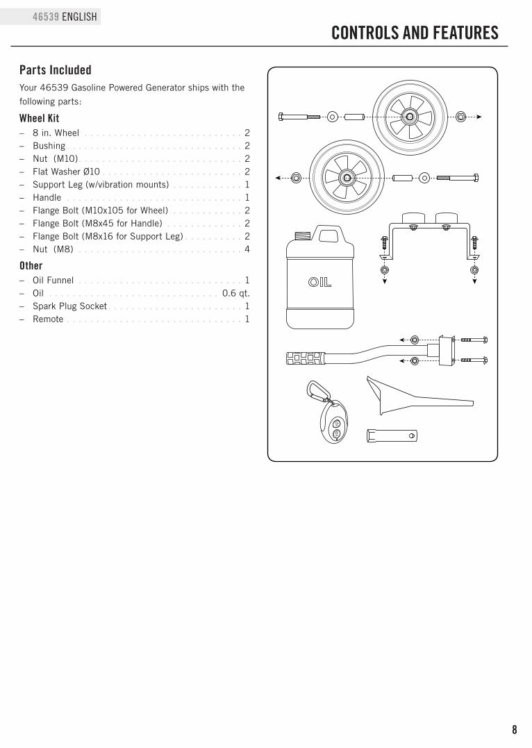
Parts Included
CONTROLS AND FEATURES
Your 46539 Gasoline Powered Generator ships with the following parts:
Wheel Kit – 8 in. Wheel . . . . . . . . . . . . . . . . . . . . . . . . . . . 2 – Bushing . . . . . . . . . . . . . . . . . . . . . . . . . . . . . . 2 – Nut (M10) . . . . . . . . . . . . . . . . . . . . . . . . . . . . 2 – Flat Washer Ø10 . . . . . . . . . . . . . . . . . . . . . . . . 2 – Support Leg (w/vibration mounts) . . . . . . . . . . . . 1 – Handle . . . . . . . . . . . . . . . . . . . . . . . . . . . . . . 1 – Flange Bolt (M10x105 for Wheel) . . . . . . . . . . . . 2 – Flange Bolt (M8x45 for Handle) . . . . . . . . . . . . . 2 – Flange Bolt (M8x16 for Support Leg) . . . . . . . . . . 2 – Nut (M8) . . . . . . . . . . . . . . . . . . . . . . . . . . . . 4
Other – Oil Funnel . . . . . . . . . . . . . . . . . . . . . . . . . . . . 1 – Oil . . . . . . . . . . . . . . . . . . . . . . . . . . . . . 0.6 qt. – Spark Plug Socket . . . . . . . . . . . . . . . . . . . . . . . 1 – Remote . . . . . . . . . . . . . . . . . . . . . . . . . . . . . . 1
9
ENGLISH 46539
ASSEMBLY
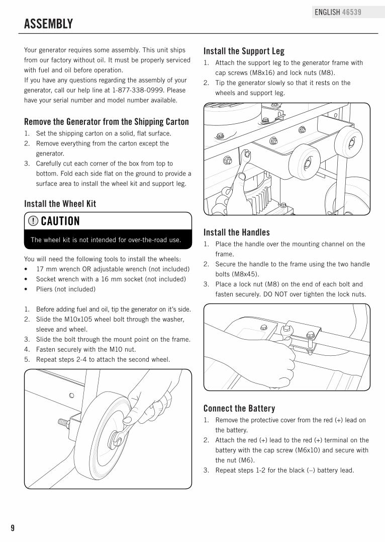
Install the Handles1. Place the handle over the mounting channel on the
frame.2. Secure the handle to the frame using the two handle
bolts (M8x45).3. Place a lock nut (M8) on the end of each bolt and
fasten securely. DO NOT over tighten the lock nuts.
Your generator requires some assembly. This unit ships from our factory without oil. It must be properly serviced with fuel and oil before operation.If you have any questions regarding the assembly of your generator, call our help line at 1-877-338-0999. Please have your serial number and model number available.
Remove the Generator from the Shipping Carton1. Set the shipping carton on a solid, flat surface.2. Remove everything from the carton except the
generator.3. Carefully cut each corner of the box from top to
bottom. Fold each side flat on the ground to provide a surface area to install the wheel kit and support leg.
Install the Wheel Kit
You will need the following tools to install the wheels:• 17 mm wrench OR adjustable wrench (not included)• Socket wrench with a 16 mm socket (not included)• Pliers (not included)
1. Before adding fuel and oil, tip the generator on it’s side.2. Slide the M10x105 wheel bolt through the washer,
sleeve and wheel.3. Slide the bolt through the mount point on the frame.4. Fasten securely with the M10 nut.5. Repeat steps 2-4 to attach the second wheel.
Install the Support Leg1. Attach the support leg to the generator frame with
cap screws (M8x16) and lock nuts (M8).2. Tip the generator slowly so that it rests on the
wheels and support leg.
The wheel kit is not intended for over-the-road use.
CAUTION
Connect the Battery1. Remove the protective cover from the red (+) lead on
the battery.2. Attach the red (+) lead to the red (+) terminal on the
battery with the cap screw (M6x10) and secure with the nut (M6).
3. Repeat steps 1-2 for the black (–) battery lead.
10
46539 ENGLISH
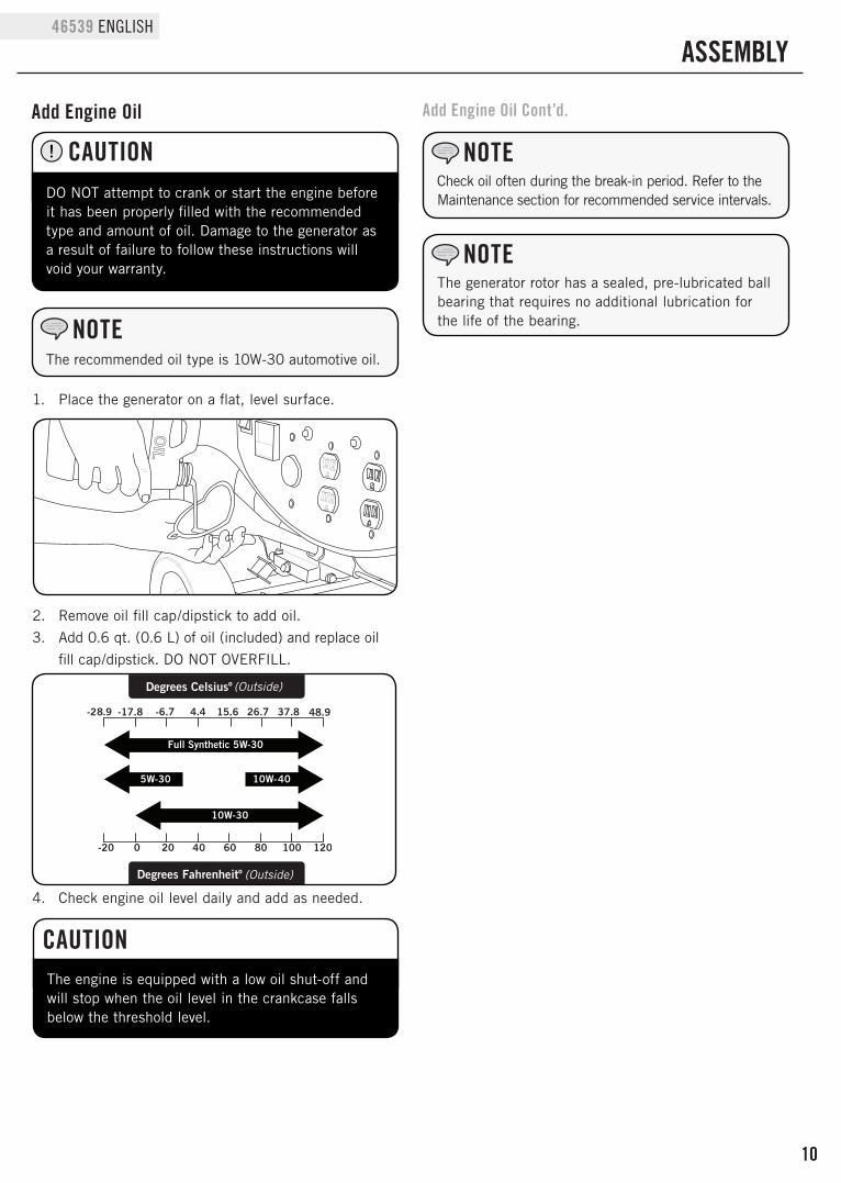
1. Place the generator on a flat, level surface.
2. Remove oil fill cap/dipstick to add oil.3. Add 0.6 qt. (0.6 L) of oil (included) and replace oil
fill cap/dipstick. DO NOT OVERFILL.
4. Check engine oil level daily and add as needed.
The engine is equipped with a low oil shut-off and will stop when the oil level in the crankcase falls below the threshold level.
CAUTION
Add Engine Oil
DO NOT attempt to crank or start the engine before it has been properly filled with the recommended type and amount of oil. Damage to the generator as a result of failure to follow these instructions will void your warranty.
CAUTION
ASSEMBLY
Check oil often during the break-in period. Refer to the Maintenance section for recommended service intervals.
NOTE
The generator rotor has a sealed, pre-lubricated ball bearing that requires no additional lubrication for the life of the bearing.
NOTE
Add Engine Oil Cont’d.
The recommended oil type is 10W-30 automotive oil.
NOTE
Full Synthetic 5W-30
Degrees Celsiusº (Outside)
(Outside)Degrees Fahrenheitº
11
ENGLISH 46539
ASSEMBLY
Add Fuel Cont’d.
GroundingYour generator must be properly connected to an appropriate ground to help prevent electric shock.
A ground terminal connected to the frame of the generator has been provided on the power panel. For remote grounding, connect of a length of heavy gauge (12 AWG minimum) copper wire between the generator ground terminal and a copper rod driven into the ground. We strongly recommend that you consult with a qualified electrician to ensure compliance with local electrical codes.
Failure to properly ground the generator can result in electric shock.
WARNING
Our engines work well with 10% or less ethanol blend fuels. When using blended fuels there are some issues worth noting: – Ethanol-gasoline blends can absorb more water
than gasoline alone. – These blends can eventually separate, leaving
water or a watery goo in the tank, fuel valve and carburetor.
– With gravity-fed fuel supplies, this compromised fuel can be drawn into the carburetor and cause damage to the engine and/or potential hazards.
– There are only a few suppliers of fuel stabilizer that are formulated to work with ethanol blend fuels.
– Any damages or hazards caused by using improper fuel, improperly stored fuel, and/or improperly formulated stabilizers, are not covered by manufacture’s warranty.
It is advisable to always shut off the fuel supply, run the engine to fuel starvation and drain the tank when the equipment is not in use for more than 30 days.
NOTE
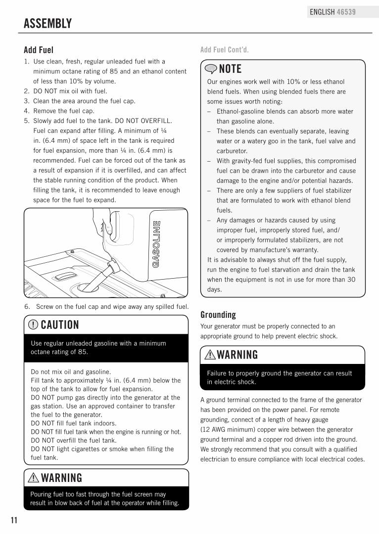
Add Fuel1. Use clean, fresh, regular unleaded fuel with a
minimum octane rating of 85 and an ethanol content of less than 10% by volume.
2. DO NOT mix oil with fuel.3. Clean the area around the fuel cap. 4. Remove the fuel cap.5. Slowly add fuel to the tank. DO NOT OVERFILL.
Fuel can expand after filling. A minimum of ¼ in. (6.4 mm) of space left in the tank is required for fuel expansion, more than ¼ in. (6.4 mm) is recommended. Fuel can be forced out of the tank as a result of expansion if it is overfilled, and can affect the stable running condition of the product. When filling the tank, it is recommended to leave enough space for the fuel to expand.
6. Screw on the fuel cap and wipe away any spilled fuel.
Use regular unleaded gasoline with a minimum octane rating of 85.
Do not mix oil and gasoline.Fill tank to approximately ¼ in. (6.4 mm) below the top of the tank to allow for fuel expansion.DO NOT pump gas directly into the generator at the gas station. Use an approved container to transfer the fuel to the generator.DO NOT fill fuel tank indoors.DO NOT fill fuel tank when the engine is running or hot.DO NOT overfill the fuel tank.DO NOT light cigarettes or smoke when filling the fuel tank.
CAUTION
Pouring fuel too fast through the fuel screen may result in blow back of fuel at the operator while filling.
WARNING
12
46539 ENGLISH
OPERATION
Generator LocationNEVER operate the generator inside any building, including garages, basements, crawlspaces and sheds, enclosure or compartment, including the generator compartment of a recreational vehicle. Please consult your local authority. In some areas, generators must be registered with the local utility. Generators used at construction sites may be subject to additional rules and regulations. Generators should be on a flat, level surface at all times. (Even while not in operation) Generators must have at least 5 ft. (1.5 m) of clearance from all combustible material. In addition to clearance from all combustible material, generators must also have at least 3 ft. (91.4 cm) of clearance on all sides to allow for adequate cooling, maintenance and servicing. Generators should never be started or operated in the back of a SUV, camper, trailer, in the bed of a truck (regular, flat or otherwise), under staircases/stairwells, next to walls or buildings, or in any other location that will not allow for adequate cooling of the generator and/or the muffler. DO NOT contain generators during operation. Allow generators to properly cool before transport or storage.Place the generator in a well-ventilated area. DO NOT place the generator near vents or intakes where exhaust fumes could be drawn into occupied or confined spaces. Carefully consider wind and air currents when positioning generator.Failure to follow proper safety precautions may void manufacturer’s warranty.
Do not operate or store the generator in rain, snow, or wet weather.
Using a generator or electrical appliance in wet conditions, such as rain or snow, or near a pool or sprinkler system, or when your hands are wet, could result in electrocution.
WARNING
WARNINGDuring operation the muffler and exhaust fumes produced will become hot. If adequate cooling and breathing space are not supplied, or if the generator is blocked or contained, temperatures can become extremely heated and may lead to fire.
Surge Protection
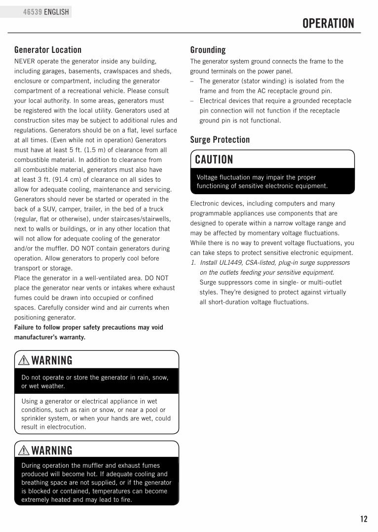
Electronic devices, including computers and many programmable appliances use components that are designed to operate within a narrow voltage range and may be affected by momentary voltage fluctuations. While there is no way to prevent voltage fluctuations, you can take steps to protect sensitive electronic equipment. 1. Install UL1449, CSA-listed, plug-in surge suppressors
on the outlets feeding your sensitive equipment. Surge suppressors come in single- or multi-outlet styles. They’re designed to protect against virtually all short-duration voltage fluctuations.
Voltage fluctuation may impair the proper functioning of sensitive electronic equipment.
CAUTION
GroundingThe generator system ground connects the frame to the ground terminals on the power panel. – The generator (stator winding) is isolated from the
frame and from the AC receptacle ground pin. – Electrical devices that require a grounded receptacle
pin connection will not function if the receptacle ground pin is not functional.
13
ENGLISH 46539
OPERATION
Wireless Remote and Electric StartWireless remote starting is only possible within 80 feet of the generator.Do not attempt to adjust the carburetor choke. The remote system will automatically close and open the choke.1. Make certain the generator is on a flat, level surface.2. Turn off all electrical loads connected to the
generator. Never start or stop the generator with electrical devices plugged in and turned on.
3. Turn the Fuel Valve to the “ON” position.4. Press the Battery Switch to “ON”.5. Press the Ignition Switch to “ON”. 6. WIRELESS REMOTE START: press and release the
“START” button on the handheld Remote Control device. DO NOT hold the button down, only press the button once. The engine will attempt to start six times.
7. A safety feature is provided which delays the electrical power availability during starting mode. The delay lasts for approximately 15 seconds. The delay is provided to prevent damage to the generator if electrical loads are inadvertently turned on during engine startup.
8. ELECTRIC START: Press and hold the ignition switch to the “START” position. Release as the engine begins to roll over. If the engine fails to start within five seconds, release the switch and wait at least ten seconds before attempting to start the engine again.
9. If the generator fails to start, check the battery condition and cable connections.
Recoil Start1. Make certain the generator is on a flat, level surface.2. Turn off all electrical loads connected to the
generator. Never start or stop the generator with electrical devices plugged in and turned on.
3. Turn the Fuel Valve to the “ON” position.4. Press the Ignition Switch to “ON”.5. Move the choke lever to the “CHOKE” position.6. Pull the starter cord slowly until resistance is felt and
then pull rapidly.7. Do not over-choke. As soon as engine starts, move
the choke lever to the “RUN” position.
If the engine starts but does not continue to run make certain that the generator is on a flat, level surface. The engine is equipped with a low oil sensor that will prevent the engine from running when the oil level falls below a critical threshold.
NOTE
When the battery switch is in the “ON” position, the switch will light up if the battery is sending out a charge. If the switch does not light up while in the “ON” position, check that the battery connection is still good.
NOTE
The supplied 12V 9AH battery does re-charge while the engine is running, but it is also recommended that the battery be fully charged at least once per month.
NOTE
Keep choke lever in “Choke” position for only 1 pull of the recoil starter. After first pull, move choke lever to the “Run” position for up to the next 3 pulls of the recoil starter. Too much choke leads to spark plug fouling/engine flooding due to the lack of incoming air. This will cause the engine not to start.
NOTE
14
46539 ENGLISH
Connecting Electrical Loads1. Let the engine stabilize and warm up for a few
minutes after starting2. Plug in and turn on the desired 120 Volt AC single
phase, 60 Hz electrical loads. – DO NOT connect 3-phase loads to the generator. – DO NOT connect 50 Hz loads to the generator. – DO NOT overload the generator.
Connecting a generator to your electric utility company’s power lines or to another power source may be against the law. In addition this action, if done incorrectly, could damage your generator and appliances and could cause serious injury or even death to you or a utility worker who may be working on nearby power lines. If you plan to run a portable electric generator during an outage, please notify your electric utility company immediately and remember to plug your appliances directly into the generator. Do not plug the generator into any electric outlet in your home. Doing so could create a connection to the utility company power lines. You are responsible for ensuring that your generator’s electricity does not feed back into the electric utility power lines.If the generator will be connected to a building electrical system, consult your local utility company or a qualified electrician. Connections must isolate generator power from utility power and must comply with all applicable laws and codes.
NOTE
OPERATION
When the stop button on the remote is pressed, power to the receptacles is turned off and the engine will stop after 5 seconds.
NOTE
Stopping the Engine1. Turn off and unplug all electrical loads. Never start
or stop the generator with electrical devices plugged in or turned on.
2. Let the generator run at no-load for several minutes to stabilize internal temperatures of the engine and generator.
3. Turn the Fuel Valve to the “OFF” position.4. Let the engine run until fuel starvation has stopped
the engine. This usually takes a few minutes.5. Press the engine switch to the “OFF” position.6. Press the battery switch to the “OFF” position.Important: Always ensure that the Fuel Valve and the Engine Switch are in the “OFF” position when the engine is not in use.
If the engine will not be used for a period of two (2) weeks or longer, please see the Storage section for proper engine and fuel storage.
NOTE
15
ENGLISH 46539
Do Not Overload GeneratorCapacityFollow these simple steps to calculate the running and starting watts necessary for your purposes. 1. Select the electrical devices you plan on running at
the same time.2. Total the running watts of these items. This is
the amount of power you need to keep your items running.
3. Identify the highest starting wattage of all devices identified in step 1. Add this number to the number calculated in step 2. Surge wattage is the extra burst of power needed to start some electric driven equipment. Following the steps listed under “Power Management” will guarantee that only one device will be starting at a time.
Power ManagementUse the following formula to convert voltage and amperage to watts:
Volts x Amps = Watts
To prolong the life of your generator and attached devices, follow these steps to add electrical load:1. Start the generator with no electrical load attached2. Allow the engine to run for several minutes to stabilize.3. Plug in and turn on the first item. It is best to attach
the item with the largest load first.4. Allow the engine to stabilize.5. Plug in and turn on the next item.6. Allow the engine to stabilize.7. Repeat steps 5-6 for each additional item.
Never exceed the specified capacity when adding loads to the generator.
NOTE
OPERATION
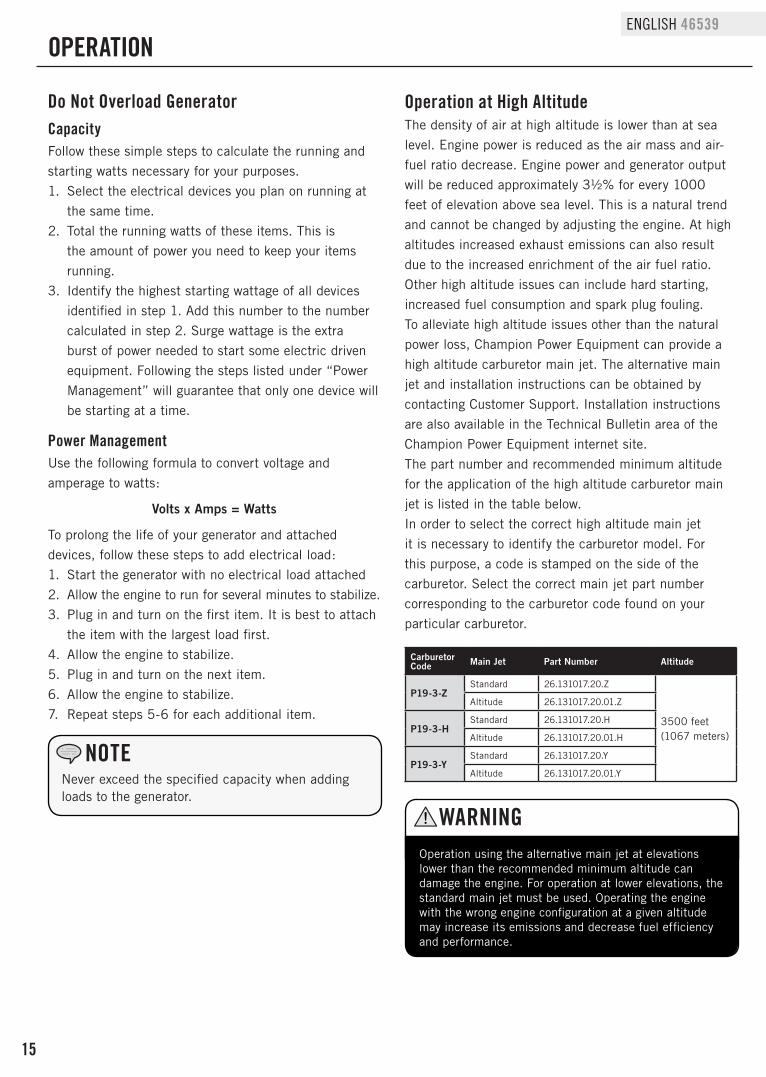
Carburetor Code Main Jet Part Number Altitude
P19-3-ZStandard 26.131017.20.Z
3500 feet(1067 meters)
Altitude 26.131017.20.01.Z
P19-3-HStandard 26.131017.20.H
Altitude 26.131017.20.01.H
P19-3-YStandard 26.131017.20.Y
Altitude 26.131017.20.01.Y
Operation at High AltitudeThe density of air at high altitude is lower than at sea level. Engine power is reduced as the air mass and air-fuel ratio decrease. Engine power and generator output will be reduced approximately 3½% for every 1000 feet of elevation above sea level. This is a natural trend and cannot be changed by adjusting the engine. At high altitudes increased exhaust emissions can also result due to the increased enrichment of the air fuel ratio. Other high altitude issues can include hard starting, increased fuel consumption and spark plug fouling.To alleviate high altitude issues other than the natural power loss, Champion Power Equipment can provide a high altitude carburetor main jet. The alternative main jet and installation instructions can be obtained by contacting Customer Support. Installation instructions are also available in the Technical Bulletin area of the Champion Power Equipment internet site.The part number and recommended minimum altitude for the application of the high altitude carburetor main jet is listed in the table below.In order to select the correct high altitude main jet it is necessary to identify the carburetor model. For this purpose, a code is stamped on the side of the carburetor. Select the correct main jet part number corresponding to the carburetor code found on your particular carburetor.
Operation using the alternative main jet at elevations lower than the recommended minimum altitude can damage the engine. For operation at lower elevations, the standard main jet must be used. Operating the engine with the wrong engine configuration at a given altitude may increase its emissions and decrease fuel efficiency and performance.
WARNING
16
46539 ENGLISH
The owner/operator is responsible for all periodic maintenance.
Complete all scheduled maintenance in a timely manner. Correct any issue before operating the generator.
Never operate a damaged or defective generator.
Tampering with the factory set governor will void your warranty.
Engine MaintenanceTo prevent accidental starting, remove and ground spark plug wire before performing any service.
OilChange oil when the engine is warm. Refer to the oil specification to select the proper grade of oil for your operating environment.1. Remove the oil drain plug with a 12 mm socket and
extension (not included).2. Allow the oil to drain completely.3. Replace the drain plug.4. Remove oil fill cap/dipstick to add oil.5. Add 0.6 qt. (0.6 L) of oil and replace oil fill
cap/dipstick. DO NOT OVERFILL.6. Dispose of used oil at an approved waste
management facility.
Air Filter1. Remove the snap-on cover holding the air filter to
the assembly.2. Remove the foam element. 3. Wash in liquid detergent and water. Squeeze
thoroughly dry in a clean cloth.4. Saturate in clean engine oil. 5. Squeeze in a clean, absorbent cloth to remove all
excess oil.6. Place the filter in the assembly.7. Reattach the air filter cover and snap in place.
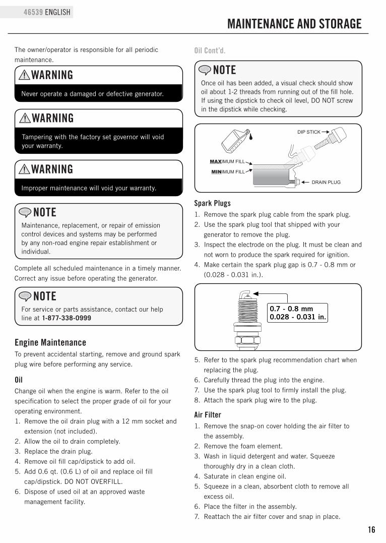
Spark Plugs1. Remove the spark plug cable from the spark plug.2. Use the spark plug tool that shipped with your
generator to remove the plug.3. Inspect the electrode on the plug. It must be clean and
not worn to produce the spark required for ignition.4. Make certain the spark plug gap is 0.7 - 0.8 mm or
(0.028 - 0.031 in.).
5. Refer to the spark plug recommendation chart when replacing the plug.
6. Carefully thread the plug into the engine.7. Use the spark plug tool to firmly install the plug.8. Attach the spark plug wire to the plug.
For service or parts assistance, contact our help line at 1-877-338-0999
NOTE
Maintenance, replacement, or repair of emission control devices and systems may be performed by any non-road engine repair establishment or individual.
NOTE
WARNING
WARNING
Improper maintenance will void your warranty.
WARNING
Oil Cont’d.
0.7 - 0.8 mm0.028 - 0.031 in.
MAINTENANCE AND STORAGE
Once oil has been added, a visual check should show oil about 1-2 threads from running out of the fill hole.If using the dipstick to check oil level, DO NOT screw in the dipstick while checking.
NOTE
17
ENGLISH 46539
AdjustmentsThe air-fuel mixture is not adjustable. Tampering with the governor can damage your generator and your electrical devices and will void your warranty. CPE recommends that you contact our service line at 1-877-338-0999 for all other service and/or adjustment needs.
Maintenance ScheduleFollow the service intervals indicated in the following maintenance schedule. Service your generator more frequently when operating in adverse conditions. Contact our helpline at 1-877-338-0999 to locate the nearest Champion Power Equipment certified service dealer for your generator or engine maintenance needs.
Use a damp cloth to clean exterior surfaces of the engine.Use a soft bristle brush to remove dirt and oil.Use an air compressor (25 PSI) to clear dirt and debris from the engine.
Cleaning
DO NOT spray engine with water.
CAUTION
Water can contaminate the fuel system.
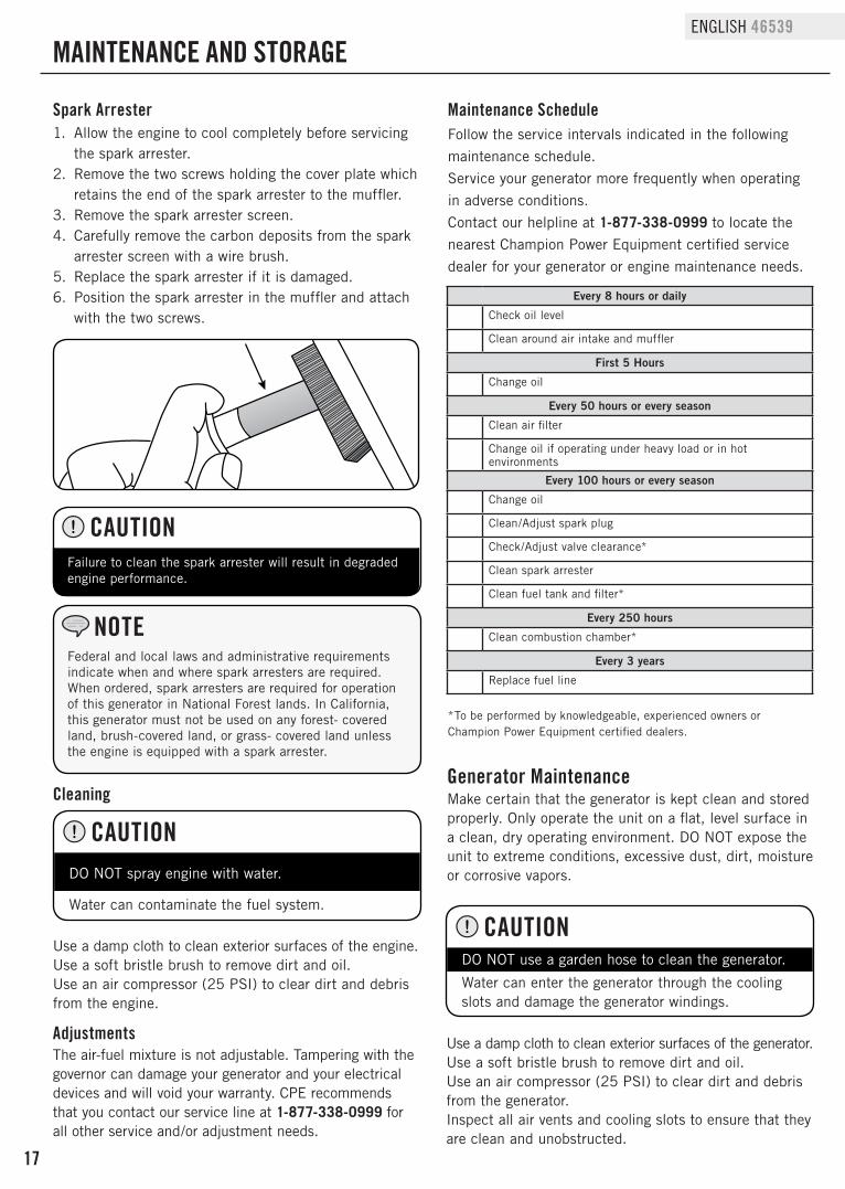
Spark Arrester1. Allow the engine to cool completely before servicing
the spark arrester.2. Remove the two screws holding the cover plate which
retains the end of the spark arrester to the muffler.3. Remove the spark arrester screen.4. Carefully remove the carbon deposits from the spark
arrester screen with a wire brush.5. Replace the spark arrester if it is damaged.6. Position the spark arrester in the muffler and attach
with the two screws.
Failure to clean the spark arrester will result in degraded engine performance.
CAUTION
MAINTENANCE AND STORAGE
Federal and local laws and administrative requirements indicate when and where spark arresters are required. When ordered, spark arresters are required for operation of this generator in National Forest lands. In California, this generator must not be used on any forest- covered land, brush-covered land, or grass- covered land unless the engine is equipped with a spark arrester.
NOTE
*To be performed by knowledgeable, experienced owners or Champion Power Equipment certified dealers.
Generator MaintenanceMake certain that the generator is kept clean and stored properly. Only operate the unit on a flat, level surface in a clean, dry operating environment. DO NOT expose the unit to extreme conditions, excessive dust, dirt, moisture or corrosive vapors.
Use a damp cloth to clean exterior surfaces of the generator.Use a soft bristle brush to remove dirt and oil.Use an air compressor (25 PSI) to clear dirt and debris from the generator. Inspect all air vents and cooling slots to ensure that they are clean and unobstructed.
DO NOT use a garden hose to clean the generator.
Water can enter the generator through the cooling slots and damage the generator windings.
CAUTION
Every 8 hours or daily
Check oil level
Clean around air intake and muffler
First 5 Hours
Change oil
Every 50 hours or every season
Clean air filter
Change oil if operating under heavy load or in hot environments
Every 100 hours or every season
Change oil
Clean/Adjust spark plug
Check/Adjust valve clearance*
Clean spark arrester
Clean fuel tank and filter*
Every 250 hours
Clean combustion chamber*
Every 3 years
Replace fuel line
18
46539 ENGLISH
MAINTENANCE AND STORAGE
StorageThe generator should be started at least once every 14 days and allowed to run for at least 20 minutes. For longer term storage, please follow these guidelines.
Generator Storage1. Add a properly formulated fuel stabilizer to the tank.2. Be sure all appliances are disconnected from the
generator.3. Run the generator for a few minutes so the treated
fuel cycles through the fuel system and carburetor.4. Turn the fuel valve to the “Off” position.5. Let the generator run until fuel starvation has
stopped the engine. This usually takes a few minutes.6. The generator needs to cool acompletely before
cleaning and storage.7. Clean the generator according to the maintenance
section.8. Change the oil.9. Remove the spark plug and pour about 1⁄2 ounce
(14.8 mL) of oil into the cylinder. Crank the engine slowly to distribute the oil and lubricate the cylinder.
10. Reattach the spark plug.11. Store the unit in a clean, dry place out of direct
sunlight.
Remote Control Battery
Generator BatteryThis product is equipped with an automatic battery charging circuit. The battery will receive charging voltage when the engine is running. The battery will maintain a proper charge if the unit is used on a regular basis (about once every two weeks). If it is used less frequently, the battery should be connected to a trickle charger or battery maintainer to keep the battery properly charged. If the battery is not able to start the engine, it can be started by manually pulling the engine recoil cord. If the battery voltage is extremely low, the charging circuit may not be able to re-charge the battery. In this case, the battery must be connected to a standard automotive style battery charger for re-charging before it can be used.
Disconnect the Battery1. Remove the protective cover from the black/negative
battery lead.2. Disconnect the black/negative lead from the black/
negative terminal on the battery and store the cap screw (M6x10) and nut (M6).
3. Repeat steps 1-2 for the red/positive battery lead.4. Store the battery in a cool, dry place.
A Float Charger will maintain the battery condition over long storage periods.
NOTE
– Always purchase the correct size and grade of battery most suitable for the intended use.
– Clean the battery contacts and also those of the device prior to battery installation.
– Remove batteries from equipment which is not to be used for an extended period of time.
– Remove batteries if consumed or if product is to be left unused for a long time.
NOTE
Charge the BatteryFor a generator equipped with batteries for electric starting, proper battery maintenance and storage should be followed. An automatic battery charger (not included) with automatic trickle charging capability should be used to charge the battery. Maximum charging rate should not exceed 1.5 amps. Follow the instructions included with the battery charger. The battery should be fully charged at least once per month.
Generator exhaust contains odorless and colorless carbon monoxide gas.
To avoid accidental or unintended ignition of your remote start generator during periods of storage, the following precautions should be followed: – When storing the generator for short periods of
time make sure that the Ignition Switch, the Fuel Valve and the Battery Switch are set in the OFF position.
– When storing the generator for extended periods of time make sure that the Ignition Switch, the Fuel Valve and the Battery Switch are set in the the the OFF position and the battery leads have been disconnected from the battery.
DANGER
19
ENGLISH 46539
Engine Specifications – Model . . . . . . . . . . . . . . . . . . . . . YF168FD-2-211 – Displacement . . . . . . . . . . . . . . . . . . . . . . .196cc – Type . . . . . . . . . . . . . . . . . . . . . . . .4-Stroke OHV – Start Type . . . . . . . . . . . . . . . . . .Wireless Remote
FCC Statement for Remote Control Device1. This device complies with Part 15 of the FCC Rules.
Operation is subject to the following two conditions: (1) This device may not cause harmful interference.(2) This device must accept any interference received, including interference that may cause undesired operation.
2. Changes or modifications not expressly approved by the party responsible for compliance could void the user’s authority to operate the equipment.
NOTE: This equipment has been tested and found to comply with the limits for a Class B digital device, pursuant to Part 15 of the FCC Rules. These limits are designed to provide reasonable protection against harmful interference in a residential installation. This equipment generates uses and can radiate radio frequency energy and, if not installed and used in accordance with the instructions, may cause harmful interference to radio communications. However, there is no guarantee that interference will not occur in a particular installation. If this equipment does cause harmful interference to radio or television reception, which can be determined by turning the equipment off and on, the user is encouraged to try to correct the interference by one or more of the following measures: – Reorient or relocate the receiving antenna. – Increase the separation between the equipment and
receiver. – Connect the equipment into an outlet on a
circuit different from that to which the receiver is connected.
Consult the dealer or an experienced radio/TV technician for help.
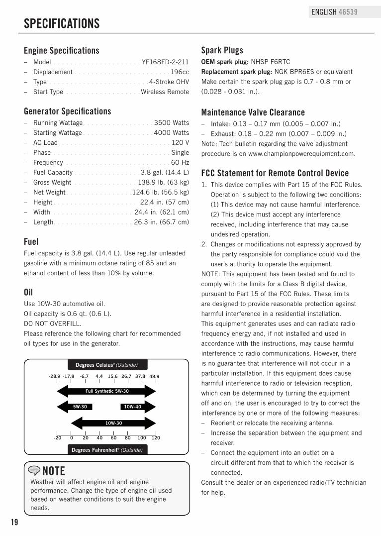
OilUse 10W-30 automotive oil.Oil capacity is 0.6 qt. (0.6 L).DO NOT OVERFILL.Please reference the following chart for recommended oil types for use in the generator.
FuelFuel capacity is 3.8 gal. (14.4 L). Use regular unleaded gasoline with a minimum octane rating of 85 and an ethanol content of less than 10% by volume.
Generator Specifications – Running Wattage . . . . . . . . . . . . . . . . . 3500 Watts – Starting Wattage . . . . . . . . . . . . . . . . . 4000 Watts – AC Load . . . . . . . . . . . . . . . . . . . . . . . . . . 120 V – Phase . . . . . . . . . . . . . . . . . . . . . . . . . . . . Single – Frequency . . . . . . . . . . . . . . . . . . . . . . . . . 60 Hz – Fuel Capacity . . . . . . . . . . . . . . . .3.8 gal. (14.4 L) – Gross Weight . . . . . . . . . . . . . . . 138.9 lb. (63 kg) – Net Weight . . . . . . . . . . . . . . . .124.6 lb. (56.5 kg) – Height . . . . . . . . . . . . . . . . . . . . 22.4 in. (57 cm) – Width . . . . . . . . . . . . . . . . . . . 24.4 in. (62.1 cm) – Length. . . . . . . . . . . . . . . . . . . 26.3 in. (66.7 cm)
SPECIFICATIONS
Maintenance Valve Clearance – Intake: 0.13 – 0.17 mm (0.005 – 0.007 in.) – Exhaust: 0.18 – 0.22 mm (0.007 – 0.009 in.)
Note: Tech bulletin regarding the valve adjustment procedure is on www.championpowerequipment.com.
Spark PlugsOEM spark plug: NHSP F6RTCReplacement spark plug: NGK BPR6ES or equivalentMake certain the spark plug gap is 0.7 - 0.8 mm or (0.028 - 0.031 in.).
Full Synthetic 5W-30
Degrees Celsiusº (Outside)
(Outside)Degrees Fahrenheitº
Weather will affect engine oil and engine performance. Change the type of engine oil used based on weather conditions to suit the engine needs.
NOTE
20
46539 ENGLISH
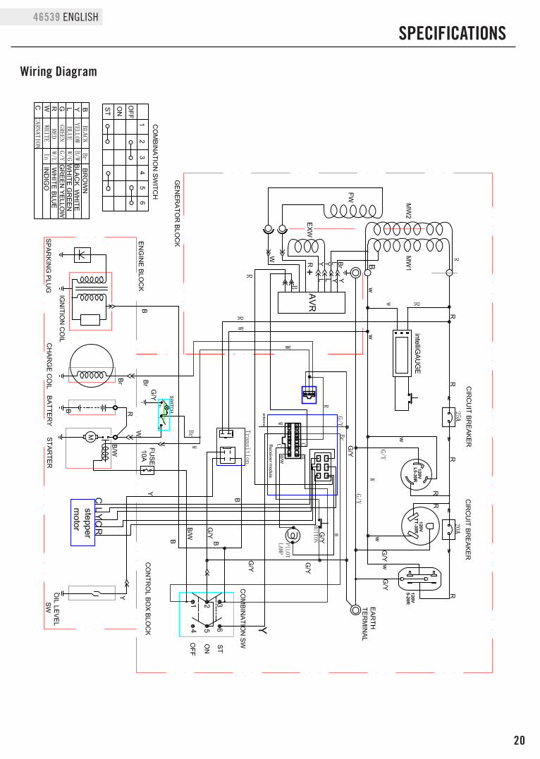
Wiring Diagram
SPECIFICATIONS
intelliGAUGE
21
ENGLISH 46539
SPECIFICATIONS
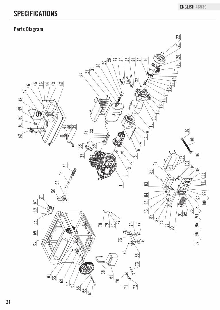
Parts Diagram
12
345678910
11121 3141516171 8
1 92 0
2122
232425262 728293031
32
333 435
36
3738
424344454647
4850
5 152
5354
5556
5960
61
6263 64
65 66 67
68
69
70
7 1 7 27 3
7 47 5
7 6 7 77 8 7 9 80
8182
8384
8 586
8 7888 9
90
91 92938 0
949 5
9 69 7
9 899
100
1011021031041051 06 1 07
1081 09
27
55
5 5
16
27
13
394041
2 7
49
17
2 2
275 7
584 9
22
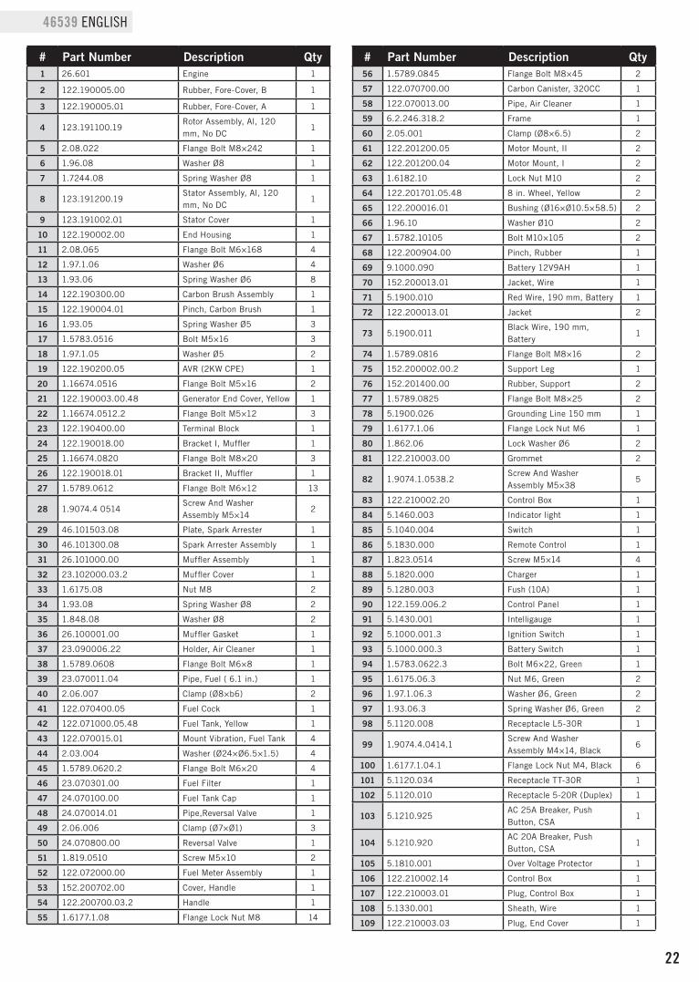
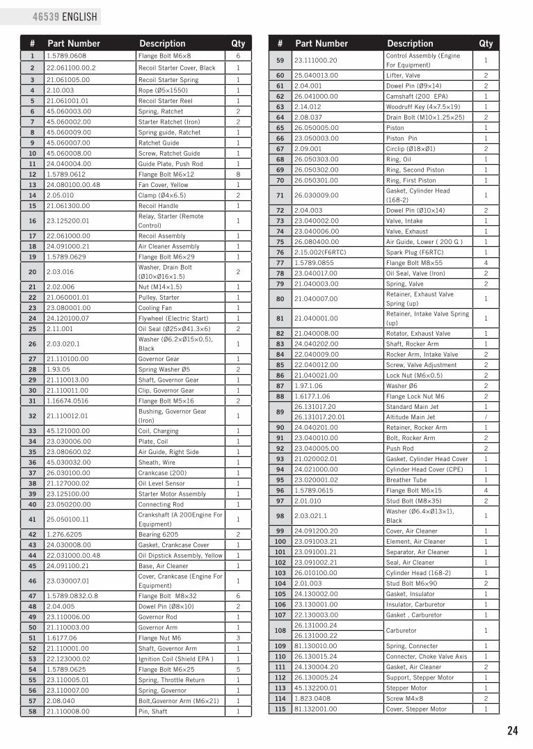
46539 ENGLISH Parts List
# Part Number Description Qty1 26.601 Engine 1
2 122.190005.00 Rubber, Fore-Cover, B 1
3 122.190005.01 Rubber, Fore-Cover, A 1
4 123.191100.19Rotor Assembly, Al, 120 mm, No DC
1
5 2.08.022 Flange Bolt M8×242 1
6 1.96.08 Washer Ø8 1
7 1.7244.08 Spring Washer Ø8 1
8 123.191200.19Stator Assembly, Al, 120 mm, No DC
1
9 123.191002.01 Stator Cover 1
10 122.190002.00 End Housing 1
11 2.08.065 Flange Bolt M6×168 4
12 1.97.1.06 Washer Ø6 4
13 1.93.06 Spring Washer Ø6 8
14 122.190300.00 Carbon Brush Assembly 1
15 122.190004.01 Pinch, Carbon Brush 1
16 1.93.05 Spring Washer Ø5 3
17 1.5783.0516 Bolt M5×16 3
18 1.97.1.05 Washer Ø5 2
19 122.190200.05 AVR (2KW CPE) 1
20 1.16674.0516 Flange Bolt M5×16 2
21 122.190003.00.48 Generator End Cover, Yellow 1
22 1.16674.0512.2 Flange Bolt M5×12 3
23 122.190400.00 Terminal Block 1
24 122.190018.00 Bracket I, Muffler 1
25 1.16674.0820 Flange Bolt M8×20 3
26 122.190018.01 Bracket II, Muffler 1
27 1.5789.0612 Flange Bolt M6×12 13
28 1.9074.4 0514Screw And Washer Assembly M5×14
2
29 46.101503.08 Plate, Spark Arrester 1
30 46.101300.08 Spark Arrester Assembly 1
31 26.101000.00 Muffler Assembly 1
32 23.102000.03.2 Muffler Cover 1
33 1.6175.08 Nut M8 2
34 1.93.08 Spring Washer Ø8 2
35 1.848.08 Washer Ø8 2
36 26.100001.00 Muffler Gasket 1
37 23.090006.22 Holder, Air Cleaner 1
38 1.5789.0608 Flange Bolt M6×8 1
39 23.070011.04 Pipe, Fuel ( 6.1 in.) 1
40 2.06.007 Clamp (Ø8×b6) 2
41 122.070400.05 Fuel Cock 1
42 122.071000.05.48 Fuel Tank, Yellow 1
43 122.070015.01 Mount Vibration, Fuel Tank 4
44 2.03.004 Washer (Ø24×Ø6.5×1.5) 4
45 1.5789.0620.2 Flange Bolt M6×20 4
46 23.070301.00 Fuel Filter 1
47 24.070100.00 Fuel Tank Cap 1
48 24.070014.01 Pipe,Reversal Valve 1
49 2.06.006 Clamp (Ø7×Ø1) 3
50 24.070800.00 Reversal Valve 1
51 1.819.0510 Screw M5×10 2
52 122.072000.00 Fuel Meter Assembly 1
53 152.200702.00 Cover, Handle 1
54 122.200700.03.2 Handle 1
55 1.6177.1.08 Flange Lock Nut M8 14
# Part Number Description Qty56 1.5789.0845 Flange Bolt M8×45 2
57 122.070700.00 Carbon Canister, 320CC 1
58 122.070013.00 Pipe, Air Cleaner 1
59 6.2.246.318.2 Frame 1
60 2.05.001 Clamp (Ø8×6.5) 2
61 122.201200.05 Motor Mount, II 2
62 122.201200.04 Motor Mount, I 2
63 1.6182.10 Lock Nut M10 2
64 122.201701.05.48 8 in. Wheel, Yellow 2
65 122.200016.01 Bushing (Ø16×Ø10.5×58.5) 2
66 1.96.10 Washer Ø10 2
67 1.5782.10105 Bolt M10×105 2
68 122.200904.00 Pinch, Rubber 1
69 9.1000.090 Battery 12V9AH 1
70 152.200013.01 Jacket, Wire 1
71 5.1900.010 Red Wire, 190 mm, Battery 1
72 122.200013.01 Jacket 2
73 5.1900.011Black Wire, 190 mm, Battery
1
74 1.5789.0816 Flange Bolt M8×16 2
75 152.200002.00.2 Support Leg 1
76 152.201400.00 Rubber, Support 2
77 1.5789.0825 Flange Bolt M8×25 2
78 5.1900.026 Grounding Line 150 mm 1
79 1.6177.1.06 Flange Lock Nut M6 1
80 1.862.06 Lock Washer Ø6 2
81 122.210003.00 Grommet 2
82 1.9074.1.0538.2Screw And Washer Assembly M5×38
5
83 122.210002.20 Control Box 1
84 5.1460.003 Indicator light 1
85 5.1040.004 Switch 1
86 5.1830.000 Remote Control 1
87 1.823.0514 Screw M5×14 4
88 5.1820.000 Charger 1
89 5.1280.003 Fush (10A) 1
90 122.159.006.2 Control Panel 1
91 5.1430.001 Intelligauge 1
92 5.1000.001.3 Ignition Switch 1
93 5.1000.000.3 Battery Switch 1
94 1.5783.0622.3 Bolt M6×22, Green 1
95 1.6175.06.3 Nut M6, Green 2
96 1.97.1.06.3 Washer Ø6, Green 2
97 1.93.06.3 Spring Washer Ø6, Green 2
98 5.1120.008 Receptacle L5-30R 1
99 1.9074.4.0414.1Screw And Washer Assembly M4×14, Black
6
100 1.6177.1.04.1 Flange Lock Nut M4, Black 6
101 5.1120.034 Receptacle TT-30R 1
102 5.1120.010 Receptacle 5-20R (Duplex) 1
103 5.1210.925AC 25A Breaker, Push Button, CSA
1
104 5.1210.920AC 20A Breaker, Push Button, CSA
1
105 5.1810.001 Over Voltage Protector 1
106 122.210002.14 Control Box 1
107 122.210003.01 Plug, Control Box 1
108 5.1330.001 Sheath, Wire 1
109 122.210003.03 Plug, End Cover 1
23
ENGLISH 46539
SPECIFICATIONS
Engine Parts Diagram
1
23
456
7891 0
1213
14
2 52627
2 930
3235
37
3812
4041
424344
46
47
2122
2324
108
107
106104
103
535 298515 04 955 5 6 5 7 58
546 0
6261
63
6 566676869707 172
74
25
751
93
94
95
9 2
9 19 0
9 7
78798 08283
848 586878 8
76
59
77
9 6
105
81
73
195 4
3931
,28
1 6
48
3 6
13 3
1 5
2 0
34
102
45101
5 1
100
64
109
110
111
112
113
115
1 14
99
89108
1 1
1 8
17
24
46539 ENGLISH
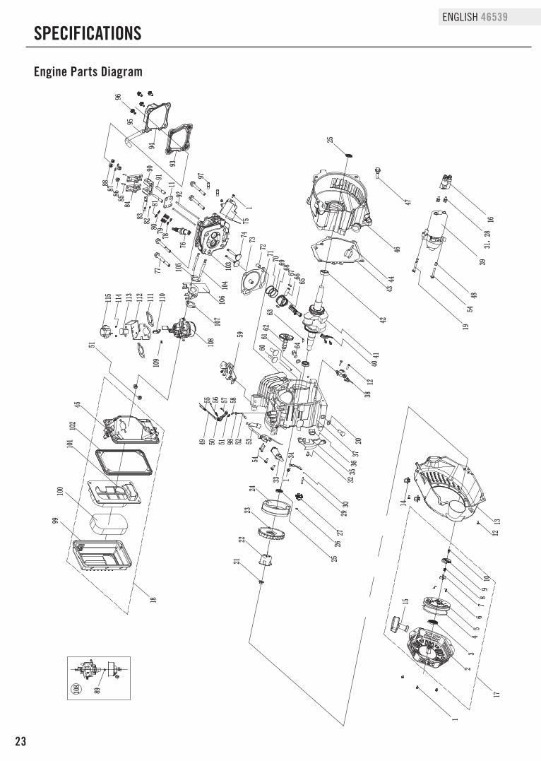
# Part Number Description Qty1 1.5789.0608 Flange Bolt M6×8 6
2 22.061100.00.2 Recoil Starter Cover, Black 1
3 21.061005.00 Recoil Starter Spring 1
4 2.10.003 Rope (Ø5×1550) 1
5 21.061001.01 Recoil Starter Reel 1
6 45.060003.00 Spring, Ratchet 2
7 45.060002.00 Starter Ratchet (Iron) 2
8 45.060009.00 Spring guide, Ratchet 1
9 45.060007.00 Ratchet Guide 1
10 45.060008.00 Screw, Ratchet Guide 1
11 24.040004.00 Guide Plate, Push Rod 1
12 1.5789.0612 Flange Bolt M6×12 8
13 24.080100.00.48 Fan Cover, Yellow 1
14 2.05.010 Clamp (Ø4×6.5) 2
15 21.061300.00 Recoil Handle 1
16 23.125200.01Relay, Starter (Remote Control)
1
17 22.061000.00 Recoil Assembly 1
18 24.091000.21 Air Cleaner Assembly 1
19 1.5789.0629 Flange Bolt M6×29 1
20 2.03.016Washer, Drain Bolt (Ø10×Ø16×1.5)
2
21 2.02.006 Nut (M14×1.5) 1
22 21.060001.01 Pulley, Starter 1
23 23.080001.00 Cooling Fan 1
24 24.120100.07 Flywheel (Electric Start) 1
25 2.11.001 Oil Seal (Ø25×Ø41.3×6) 2
26 2.03.020.1Washer (Ø6.2×Ø15×0.5), Black
1
27 21.110100.00 Governor Gear 1
28 1.93.05 Spring Washer Ø5 2
29 21.110013.00 Shaft, Governor Gear 1
30 21.110011.00 Clip, Governor Gear 1
31 1.16674.0516 Flange Bolt M5×16 2
32 21.110012.01Bushing, Governor Gear (Iron)
1
33 45.121000.00 Coil, Charging 1
34 23.030006.00 Plate, Coil 1
35 23.080600.02 Air Guide, Right Side 1
36 45.030032.00 Sheath, Wire 1
37 26.030100.00 Crankcase (200) 1
38 21.127000.02 Oil Level Sensor 1
39 23.125100.00 Starter Motor Assembly 1
40 23.050200.00 Connecting Rod 1
41 25.050100.11Crankshaft (A 200Engine For Equipment)
1
42 1.276.6205 Bearing 6205 2
43 24.030008.00 Gasket, Crankcase Cover 1
44 22.031000.00.48 Oil Dipstick Assembly, Yellow 1
45 24.091100.21 Base, Air Cleaner 1
46 23.030007.01Cover, Crankcase (Engine For Equipment)
1
47 1.5789.0832.0.8 Flange Bolt M8×32 6
48 2.04.005 Dowel Pin (Ø8×10) 2
49 23.110006.00 Governor Rod 1
50 21.110003.00 Governor Arm 1
51 1.6177.06 Flange Nut M6 3
52 21.110001.00 Shaft, Governor Arm 1
53 22.123000.02 Ignition Coil (Shield EPA ) 1
54 1.5789.0625 Flange Bolt M6×25 5
55 23.110005.01 Spring, Throttle Return 1
56 23.110007.00 Spring, Governor 1
57 2.08.040 Bolt,Governor Arm (M6×21) 1
58 21.110008.00 Pin, Shaft 1
# Part Number Description Qty
59 23.111000.20Control Assembly (Engine For Equipment)
1
60 25.040013.00 Lifter, Valve 2
61 2.04.001 Dowel Pin (Ø9×14) 2
62 26.041000.00 Camshaft (200 EPA) 1
63 2.14.012 Woodruff Key (4×7.5×19) 1
64 2.08.037 Drain Bolt (M10×1.25×25) 2
65 26.050005.00 Piston 1
66 23.050003.00 Piston Pin 1
67 2.09.001 Circlip (Ø18×Ø1) 2
68 26.050303.00 Ring, Oil 1
69 26.050302.00 Ring, Second Piston 1
70 26.050301.00 Ring, First Piston 1
71 26.030009.00Gasket, Cylinder Head (168-2)
1
72 2.04.003 Dowel Pin (Ø10×14) 2
73 23.040002.00 Valve, Intake 1
74 23.040006.00 Valve, Exhaust 1
75 26.080400.00 Air Guide, Lower ( 200 G ) 1
76 2.15.002(F6RTC) Spark Plug (F6RTC) 1
77 1.5789.0855 Flange Bolt M8×55 4
78 23.040017.00 Oil Seal, Valve (Iron) 2
79 21.040003.00 Spring, Valve 2
80 21.040007.00Retainer, Exhaust Valve Spring (up)
1
81 21.040001.00Retainer, Intake Valve Spring (up)
1
82 21.040008.00 Rotator, Exhaust Valve 1
83 24.040202.00 Shaft, Rocker Arm 1
84 22.040009.00 Rocker Arm, Intake Valve 2
85 22.040012.00 Screw, Valve Adjustment 2
86 21.040021.00 Lock Nut (M6×0.5) 2
87 1.97.1.06 Washer Ø6 2
88 1.6177.1.06 Flange Lock Nut M6 2
8926.131017.20 Standard Main Jet 1
26.131017.20.01 Altitude Main Jet /
90 24.040201.00 Retainer, Rocker Arm 1
91 23.040010.00 Bolt, Rocker Arm 2
92 23.040005.00 Push Rod 2
93 21.020002.01 Gasket, Cylinder Head Cover 1
94 24.021000.00 Cylinder Head Cover (CPE) 1
95 23.020001.02 Breather Tube 1
96 1.5789.0615 Flange Bolt M6×15 4
97 2.01.010 Stud Bolt (M8×35) 2
98 2.03.021.1Washer (Ø6.4×Ø13×1), Black
1
99 24.091200.20 Cover, Air Cleaner 1
100 23.091003.21 Element, Air Cleaner 1
101 23.091001.21 Separator, Air Cleaner 1
102 23.091002.21 Seal, Air Cleaner 1
103 26.010100.00 Cylinder Head (168-2) 1
104 2.01.003 Stud Bolt M6×90 2
105 24.130002.00 Gasket, Insulator 1
106 23.130001.00 Insulator, Carburetor 1
107 22.130003.00 Gasket , Carburetor 1
10826.131000.24
Carburetor 126.131000.22
109 81.130010.00 Spring, Connecter 1
110 26.130015.24 Connecter, Choke Valve Axis 1
111 24.130004.20 Gasket, Air Cleaner 2
112 26.130005.24 Support, Stepper Motor 1
113 45.132200.01 Stepper Motor 1
114 1.823.0408 Screw M4×8 2
115 81.132001.00 Cover, Stepper Motor 1
25
ENGLISH 46539
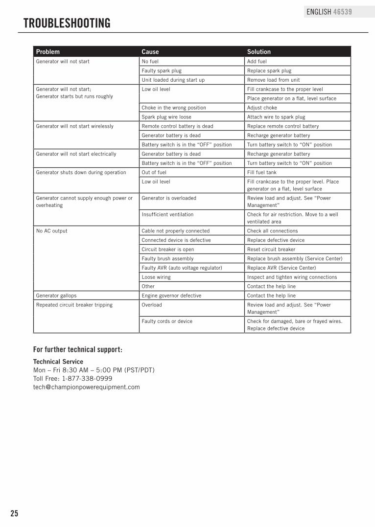
TROUBLESHOOTING
For further technical support:Technical ServiceMon – Fri 8:30 AM – 5:00 PM (PST/PDT)Toll Free: [email protected]
Problem Cause SolutionGenerator will not start No fuel Add fuel
Faulty spark plug Replace spark plug
Unit loaded during start up Remove load from unit
Generator will not start;Generator starts but runs roughly
Low oil level Fill crankcase to the proper level
Place generator on a flat, level surface
Choke in the wrong position Adjust choke
Spark plug wire loose Attach wire to spark plug
Generator will not start wirelessly Remote control battery is dead Replace remote control battery
Generator battery is dead Recharge generator battery
Battery switch is in the “OFF” position Turn battery switch to “ON” position
Generator will not start electrically Generator battery is dead Recharge generator battery
Battery switch is in the “OFF” position Turn battery switch to “ON” position
Generator shuts down during operation Out of fuel Fill fuel tank
Low oil level Fill crankcase to the proper level. Place generator on a flat, level surface
Generator cannot supply enough power or overheating
Generator is overloaded Review load and adjust. See “Power Management”
Insufficient ventilation Check for air restriction. Move to a well ventilated area
No AC output Cable not properly connected Check all connections
Connected device is defective Replace defective device
Circuit breaker is open Reset circuit breaker
Faulty brush assembly Replace brush assembly (Service Center)
Faulty AVR (auto voltage regulator) Replace AVR (Service Center)
Loose wiring Inspect and tighten wiring connections
Other Contact the help line
Generator gallops Engine governor defective Contact the help line
Repeated circuit breaker tripping Overload Review load and adjust. See “Power Management”
Faulty cords or device Check for damaged, bare or frayed wires. Replace defective device
WARRANTY*CHAMPION POWER EQUIPMENT
2 YEAR LIMITED WARRANTY
Warranty QualificationsChampion Power Equipment (CPE) will register this warranty upon receipt of your Warranty Registration Card and a copy of your sales receipt from one of CPE’s retail locations as proof of purchase.Please submit your warranty registration and your proof of purchase within ten (10) days of the date of purchase.
Repair/Replacement WarrantyCPE warrants to the original purchaser that the mechanical and electrical components will be free of defects in material and workmanship for a period of two years (parts and labor) from the original date of purchase and 180 days (parts and labor) for commercial and industrial use. Transportation charges on product submitted for repair or replacement under this warranty are the sole responsibility of the purchaser. This warranty only applies to the original purchaser and is not transferable.
Do Not Return The Unit To The Place Of PurchaseContact CPE’s Technical Service and CPE will troubleshoot any issue via phone or e-mail. If the problem is not corrected by this method, CPE will, at its option, authorize evaluation, repair or replacement of the defective part or component at a CPE Service Center. CPE will provide you with a case number for warranty service. Please keep it for future reference. Repairs or replacements without prior authorization, or at an unauthorized repair facility, will not be covered by this warranty.
Warranty ExclusionsThis warranty does not cover the following repairs and equipment:
Normal WearProducts with mechanical and electrical components need periodic parts and service to perform well. This warranty does not cover repair when normal use has exhausted the life of a part or the equipment as a whole.
Installation, Use and MaintenanceThis warranty will not apply to parts and/or labor if the product is deemed to have been misused, neglected, involved in an accident, abused, loaded beyond the product’s limits, modified, installed improperly or connected incorrectly to any electrical component. Normal maintenance is not covered by this warranty and is not required to be performed at a facility or by a person authorized by CPE.
Other ExclusionsThis warranty excludes: – Cosmetic defects such as paint, decals, etc. – Wear items such as filter elements, o-rings, etc.
– Accessory parts such as starting batteries, and storage covers. – Failures due to acts of God and other force majeure events
beyond the manufacturer’s control. – Problems caused by parts that are not original Champion Power
Equipment parts.When applicable, this warranty does not apply to products used for prime power in place of a utility.
Limits of Implied Warranty and Consequential DamageChampion Power Equipment disclaims any obligation to cover any loss of time, use of this product, freight, or any incidental or consequential claim by anyone from using this product. THIS WARRANTY AND THE ATTACHED U.S. EPA, CARB and/or ECCC EMISSION CONTROL SYSTEM WARRANTIES (WHEN APPLICABLE) ARE IN LIEU OF ALL OTHER WARRANTIES, EXPRESS OR IMPLIED, INCLUDING WARRANTIES OF MERCHANTABILITY OR FITNESS FOR A PARTICULAR PURPOSE. A unit provided as an exchange will be subject to the warranty of the original unit. The length of the warranty governing the exchanged unit will remain calculated by reference to the purchase date of the original unit.This warranty gives you certain legal rights which may change from state to state or province to province. Your state or province may also have other rights you may be entitled to that are not listed within this warranty.
Contact Information
AddressChampion Power Equipment, Inc.Customer Service12039 Smith Ave.Santa Fe Springs, CA 90670 USAwww.championpowerequipment.com
Customer ServiceMon – Fri 8:30 AM – 5:00 PM (PST/PDT)Toll Free: [email protected] no.: 1-562-236-9429
Technical ServiceMon – Fri 8:30 AM – 5:00 PM (PST/PDT)Toll Free: [email protected]/7 Tech Support: 1-562-204-1188
WARRANTY
* Except as otherwise stipulated in any of the following enclosed Emission Control System Warranties (when applicable) for the Emission Control System: U.S. Environment Protection Agency (EPA), California Air Resources Board (CARB) and/or Environment and Climate Change Canada (ECCC).
Champion Power Equipment, Inc. (CPE), The United States Environment Protection Agency (U.S. EPA.) and the California Air Resources Board (CARB)
Emission Control System Warranty Your Champion Power Equipment (CPE) engine complies with both the U.S. EPA and state of California Air Resources Board (CARB) emission regulations. YOUR WARRANTY RIGHTS AND OBLIGATIONS: The US EPA, California Air Resources Board, and CPE are pleased to explain the Federal and California Emission Control Systems Warranty on your 2016 small off-road engine and engine powered equipment. In California, new, small off-road engines and new equipment that use small off-engines must be designed, built and equipped to meet the State’s stringent anti smog standards. In the other states, new engines and equipment must be designed, built and equipped, at the time of sale, to meet U.S. EPA regulations for small non-road engines. CPE warrants the emission control system on your small off-road engine and equipment for the period of time listed below, provided there has been no abuse, neglect, unapproved modification, or improper maintenance of your equipment. Your emission control system may include parts such as the carburetor, fuel-injection system, the ignition system, catalytic converter and fuel lines. Also included may be hoses, belts, connectors and other emission related assemblies. Where a warrantable condition exits, CPE will repair your small off-road engine at no cost to you including diagnosis, parts and labor. For engines less than or equal to 80cc, only the fuel tank and fuel line is subject to the evaporative emission control warranty requirements of this section. MANUFACTURER’S EMISSION CONTROL SYSTEM WARRANTY COVERAGE: This emission control system is warranted for two years, subject to provisions set forth below. If, during the warranty period, emission related part on your engine is defective in materials or workmanship, the part will be repaired or replaced by CPE. OWNER WARRANTY RESPONSIBILITIES: As the small off-road engine owner, you are responsible for the performance of the required maintenance listed in your Owner’s Manual. CPE recommends that you retain all your receipts covering maintenance on your small off-road engine, but CPE cannot deny warranty solely for the lack of receipts or for your failure to ensure the performance of all scheduled maintenance. As the small off-road engine owner, you should however be aware that CPE may deny you warranty coverage if your small, off-road engine or a part has failed due to abuse, neglect, improper maintenance or unapproved modifications. You are responsible for presenting your small off-road engine to an Authorized CPE service outlet or alternate service outlet as described in (3)(f.) below, CPE dealer or CPE, Santa Fe Springs, Ca. as soon as a problem exists. The warranty repairs should be completed in a reasonable amount of time, not to exceed 30 days. If you have any questions regarding your warranty rights and responsibilities, you should contact:
Champion Power Equipment, Inc. Customer Service 12039 Smith Ave.
Santa Fe Springs, CA 90670 1-877-338-0999

EMISSION CONTROL SYSTEM WARRANTY The following are specific provisions relative to your Emission Control System (ECS) Warranty Coverage. 1. APPLICABILITY: This warranty shall apply to 1995 and later model year California small off-road engines (for other states, 1997 and later model year engines). The ECS Warranty Period shall begin on the date the new engine or equipment is delivered to its original, end-use purchaser, and shall continue for 24 consecutive months thereafter. 2. GENERAL EMISSIONS WARRANTY COVERAGE CPE warrants to the original, end-use purchaser of the new engine or equipment and to each subsequent purchaser that each of its small off-road engines is: a. Designed, built and equipped so as to conform to U.S. EPA emissions standards for spark-ignited engines at or below 19 kilowatts and all applicable regulations adopted by the California Air Resources Board and b. Free from defects in materials and workmanship that cause the failure of a warranted part to be identical in all material respects to the part as described in the engine manufacturer’s application for certification for a period of two years. 3. THE WARRANTY ON EMISSION-RELATED PARTS WILL BE INTERPRETED AS FOLLOWS: a. Any warranted part that is not scheduled for replacement as required maintenance in the Owners Manual shall be warranted for the ECS Warranty Period. If any such part fails during the ECS Warranty Period, it shall be repaired or replaced by CPE according to Subsection “d” below. Any such part repaired or replaced under the ECS Warranty shall be warranted for any remainder of the ECS Warranty Period. b. Any warranted, emissions-related part which is scheduled only for regular inspection as specified in the Owners Manual shall be warranted for the ECS Warranty Period. A statement in such written instructions to the effect of “repair or replace as necessary”, shall not reduce the ECS Warranty Period. Any such part repaired or replaced under the ECS Warranty shall be warranted for the remainder of the ECS Warranty Period. c. Any warranted, emissions-related part which is scheduled for replacement as required maintenance in the Owner’s Manual shall be warranted for the period of time prior to the first scheduled replacement point for that part. If the part fails prior to the first scheduled replacement, the part shall be repaired or replaced by CPE according to Subsection “d” below. Any such emissions-related part repaired or replaced under the ECS Warranty, shall be warranted for the remainder of the ECS Warranty Period prior to the first scheduled replacement point for such emissions-related part. d. Repair or replacement of any warranted, emissions-related part under this ECS Warranty shall be performed at no charge to the owner at a CPE Authorized Service Outlet. e. The owner shall not be charged for diagnostic labor which leads to the determination that a part covered by the ECS Warranty is in fact defective, provided that such diagnostic work is performed at a CPE Authorized Service Outlet. f. CPE shall pay for covered emissions warranty repairs at non-authorized service outlets under the following circumstances: i. The service is required in a population center with a population over 100,000 according to U.S. Census 2000 without a CPE Authorized Service Outlet AND ii. The service is required more than 100 miles from a CPE Authorized Service Outlet. The 100 mile limitation does not apply in the following states: Alaska, Arizona, Colorado, Hawaii, Idaho, Montana, Nebraska, Nevada, New Mexico, Oregon, Texas, Utah and Wyoming. g. CPE shall be liable for damages to other original engine components or approved modifications proximately caused by a failure under warranty of an emission-related part covered by the ECS Warranty. h. Throughout the ECS Warranty Period, CPE shall maintain a supply of warranted emission-related parts sufficient to meet the expected demand for such emission-related parts. i. Any CPE Authorized and approved emission-related replacement part may be used in the performance of any ECS Warranty maintenance or repair and will be provided without charge to the owner. Such use shall not reduce CPE’s warranty obligation. j. Unapproved add-on or modified parts may not be used to modify or repair a CPE engine. Such use voids this ECS Warranty and shall be sufficient grounds for disallowing an ECS Warranty claim. CPE shall not be liable hereunder for failures of any warranted parts of a CPE engine caused by the use of such an unapproved add-on or modified part.
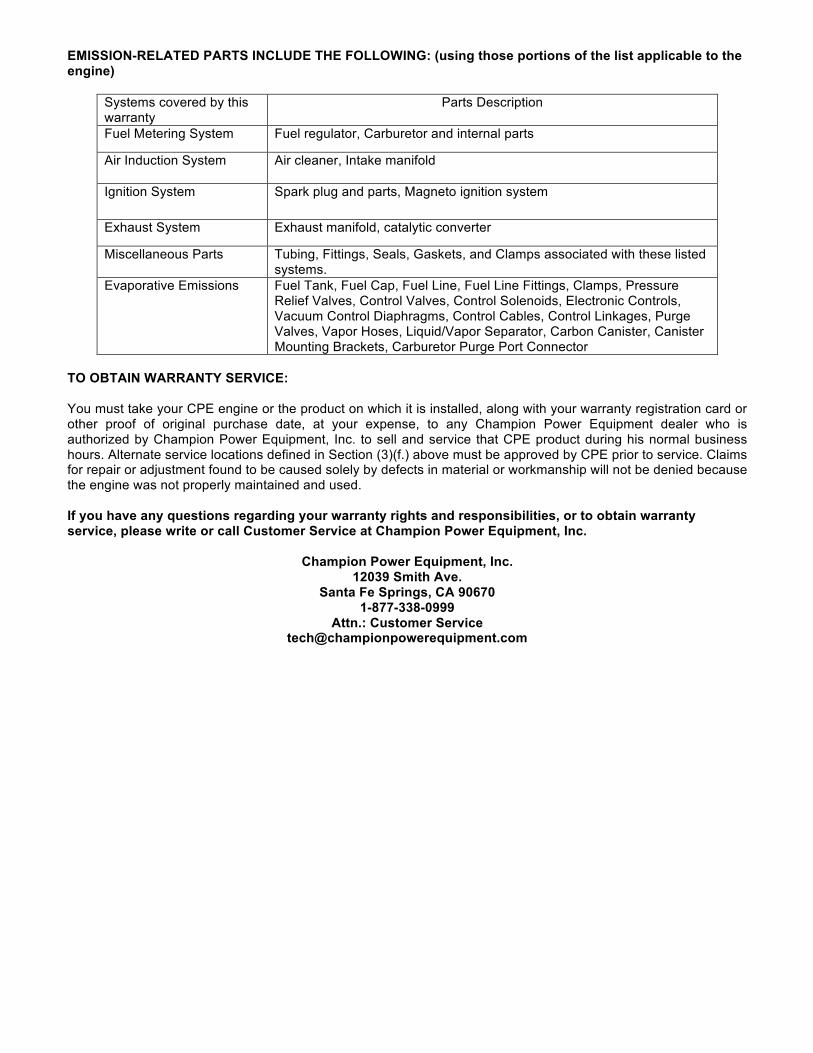
EMISSION-RELATED PARTS INCLUDE THE FOLLOWING: (using those portions of the list applicable to the engine)
Systems covered by this warranty
Parts Description
Fuel Metering System Fuel regulator, Carburetor and internal parts
Air Induction System Air cleaner, Intake manifold
Ignition System Spark plug and parts, Magneto ignition system
Exhaust System Exhaust manifold, catalytic converter
Miscellaneous Parts Tubing, Fittings, Seals, Gaskets, and Clamps associated with these listed systems.
Evaporative Emissions Fuel Tank, Fuel Cap, Fuel Line, Fuel Line Fittings, Clamps, Pressure Relief Valves, Control Valves, Control Solenoids, Electronic Controls, Vacuum Control Diaphragms, Control Cables, Control Linkages, Purge Valves, Vapor Hoses, Liquid/Vapor Separator, Carbon Canister, Canister Mounting Brackets, Carburetor Purge Port Connector
TO OBTAIN WARRANTY SERVICE: You must take your CPE engine or the product on which it is installed, along with your warranty registration card or other proof of original purchase date, at your expense, to any Champion Power Equipment dealer who is authorized by Champion Power Equipment, Inc. to sell and service that CPE product during his normal business hours. Alternate service locations defined in Section (3)(f.) above must be approved by CPE prior to service. Claims for repair or adjustment found to be caused solely by defects in material or workmanship will not be denied because the engine was not properly maintained and used. If you have any questions regarding your warranty rights and responsibilities, or to obtain warranty service, please write or call Customer Service at Champion Power Equipment, Inc.
Champion Power Equipment, Inc.
12039 Smith Ave. Santa Fe Springs, CA 90670
1-877-338-0999 Attn.: Customer Service