Embed Size (px)
Citation preview

Ⅱ
Portable Automatic Gas Cutter
Operation Manual – Version T89001732
For every person who will be engaged in operation and maintenance
supervision, it is recommended to read through this manual before any
operations, so as to permit optimum operation of this machine.
1

2
INTRODUCTION Thank you very much for purchasing this product. Read this instruction manual thoroughly to ensure correct, safe and effective use of the machine. Read the manual first to understand how to operate and maintain the machine. Cooperation between colleagues in the workplace is essential for safe, smooth operation. Make sure you read, understand and take all necessary safety precautions.
SAFETY PRECAUTIONS This product is designed to be safe, but it can cause serious accidents if not operated correctly. Those who operate and repair this machine must read this manual thoroughly before operating, inspecting and maintaining the machine. Keep the manual near the machine so that anyone operates the machine can refer to it as necessary. ■Do not use the machine carelessly without following the instructions in the manual.
■Use the machine only after you have completely understood the contents of the manual.
■If an explanation in the manual is difficult to understand, contact our company or sales service office.
■Keep the manual to hand at all times and read it as many times as is necessary for a complete
understanding.
■If the manual becomes lost or damaged, place an order with our company or sales service office for a
new one.
■When transferring the machine to a new owner, be sure to hand over this instruction manual as well.
QUALIFICATIONS FOR MACHINE OPERATOR Operators and repair staff of this machine must completely understand the contents of the instruction manual and have either of the following qualifications: 1. Gas welding foremen’s license
2. Completion of gas welding training course
3. Approval by the Minister of Labor
3
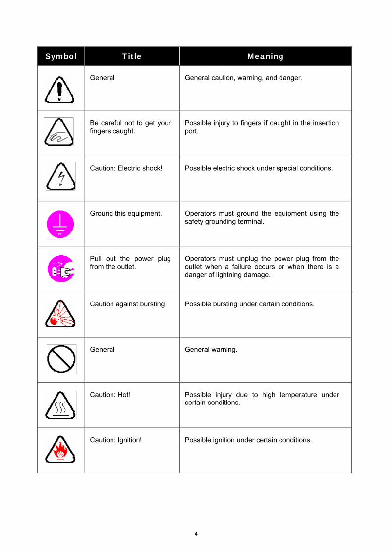
Symbol Title Meaning
General
General caution, warning, and danger.
Be careful not to get your fingers caught.
Possible injury to fingers if caught in the insertion port.
Caution: Electric shock!
Possible electric shock under special conditions.
Ground this equipment.
Operators must ground the equipment using the safety grounding terminal.
Pull out the power plug from the outlet.
Operators must unplug the power plug from the outlet when a failure occurs or when there is a danger of lightning damage.
Caution against bursting
Possible bursting under certain conditions.
General
General warning.
Caution: Hot!
Possible injury due to high temperature under certain conditions.
Caution: Ignition!
Possible ignition under certain conditions.
4
PICLE1-Ⅱ
- 1 -
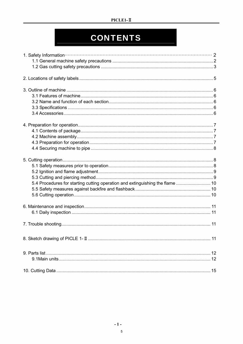
CONTENTS 1. Safety Information································································································· 2
1.1 General machine safety precautions ............................................................................... 2 1.2 Gas cutting safety precautions ........................................................................................ 3
2. Locations of safety labels ......................................................................................................... 5 3. Outline of machine ................................................................................................................... 6
3.1 Features of machine........................................................................................................ 6 3.2 Name and function of each section.................................................................................. 6 3.3 Specifications .................................................................................................................. 6 3.4 Accessories ..................................................................................................................... 6
4. Preparation for operation.......................................................................................................... 7
4.1 Contents of package........................................................................................................ 7 4.2 Machine assembly........................................................................................................... 7 4.3 Preparation for operation.................................................................................................7 4.4 Securing machine to pipe ................................................................................................ 8
5. Cutting operation...................................................................................................................... 8
5.1 Safety measures prior to operation.................................................................................. 8 5.2 Ignition and flame adjustment.......................................................................................... 9 5.3 Cutting and piercing method............................................................................................ 9 5.4 Procedures for starting cutting operation and extinguishing the flame ........................... 10 5.5 Safety measures against backfire and flashback........................................................... 10 5.6 Cutting operation........................................................................................................... 10
6. Maintenance and inspection................................................................................................... 11
6.1 Daily inspection ............................................................................................................. 11 7. Trouble shooting..................................................................................................................... 11
8. Sketch drawing of PICLE 1-Ⅱ................................................................................................ 11
9. Parts list ................................................................................................................................. 12
9.1Main units....................................................................................................................... 12 10. Cutting Data ......................................................................................................................... 15
5
PICLE1-Ⅱ
- 2 -
1 Safety information Operation, inspection, and maintenance that disregard the basic safety rules cause many accidents. Carefully read, understand, and master the safety measures and precautions described in this instruction manual and on the machine before operating, inspecting, and maintaining the machine. The safety messages are classified as indicated on the machine safety labels:
■WARNING This word is used in a warning message and a warning label is positioned at places that could cause injury or serious accident.
■CAUTION This word is used in a caution message and a caution label is positioned at places that could cause slight injury or machine damage. This is also used as a caution for frequent dangerous actions.
■NOTICE SIGNS This is a sign to show machine operators and maintenance engineers items that relate directly to damage of machines and surrounding facilities and equipment.
1.1 General machine safety precautions Read and fully understand the following important safety information:
1.1.1 Machine safety 1. The machine casing is mainly made of aluminum alloy to reduce weight. For this reason, be careful
not to drop a heavy item on the machine, or not drop the machine when carrying it, since the alloy is not designed to withstand such impact.
2. When mounting hoses to the torch and distributor, tighten the nut with the attached wrench. After mounting, be sure to check there is no gas leak with a detection liquid. If a gas leak is found, retighten the nut firmly.
3. When fixing a tip to the torch, tighten the nut with the two wrenches attached. In addition, avoid damaging the taper part of the tip since this may cause backfire.
4. Never disassemble the machine other than during maintenance and inspection. Otherwise, malfunction will result.
5. Never remodel the machine. Remodeling is very dangerous. 6. Never use the machine outdoors when the weather is wet. This will cause failure of the machine and
could cause a fatal accident by electric shock.
1.1.2 Safety clothing
1. Be sure to wear protectors (gauntlets, goggles, helmet, and safety shoes) during operation.
6
PICLE1-Ⅱ
- 3 -
1.1.3 Operation and handling safety precautions
1. Read this instruction manual before operating the machine. 2. Mount and center the machine correctly and confirm correct motion before operation. 3. Prior to operating the machine, check the safety of the surroundings to avoid accidents. 4. Never move the machine while the preheat flame is on. 5. Take great care of spatters and dross when operating the machine at a high position. They may
injure people below. 6. Do not hit any object against the surface of the wheel to be in touch with pipes or drop the
wheel so as not to scratch the surface; otherwise knocking will result. 7. Week chain tension will make the machine slip. Give an appropriate tension to the chain. 8. Be careful not to get your hand caught between the upper plate and slide bracket. 9. When stretching the chain, be careful not to get your hand caught in the wing bolt.
10. Do not insert your hand into rotary sections (sprocket and wheel). 11. Be careful not to drop the machine when changing the chain. 12. Do not use deformed or rusted chains; otherwise the chain may be disengaged. 13. Do not mistake the top and bottom sides of the chain. 14. The number of chains must match the pipes. 15. Do not place the machine on pipes when it is unused. 16. Be careful not to damage the wheel. 17. The planer deflection due to a worm wheel causes curved cutting surfaces and discrepancy
between the first and last cutting positions.
1.1.4 Maintenance and inspection precautions 1. Ask a qualified electrician to perform repair and inspection service. 2. Maintain the machine periodically.
1.2 Gas cutting safety precautions
Strictly observe the safety rules and precautions to ensure the safety of gas cutting operations. Operators and supervisors MUST keep safety in mind.
1.2.1 Prevention of explosion 1. Never cut pressurized cylinders or hermetically sealed containers. 2. Ensure sufficient ventilation for gas cutting to prevent the air from becoming stale.
1.2.2 Pressure regulator safety precautions 1. Before starting operation, check that all pressure regulators are operating correctly. 2. Ask a skilled repair engineer to perform maintenance and inspection service. 3. Do not use pressure regulators from which gas is leaking, nor malfunctioning pressure regulators. 4. Do not use pressure regulators smeared with oil or grease.
7
PICLE1-Ⅱ
- 4 -
1.2.3 High Pressure gas cylinder safety precautions 1. Never use broken cylinders or cylinders from which gas are leaking. 2. Install cylinders upright and take measures to prevent them from falling. 3. Use cylinders only for specified purposes. 4. Do not smear container valves with oil or grease. 5. Install cylinders in a place free from heat, sparks, slag, and open flame. 6. Contact the distributor if the container valves will not open.
Never use a hammer, wrench, or other tools to forcibly open container valves.
1.2.4 Safety precautions for hoses 1. Use the oxygen hose for oxygen gas only. 2. Replace cracked hoses or other hoses damaged by sparks, heat, unshielded fire, etc. 3. Install hoses without twisting. 4. To prevent breakage of hoses, take great care during operation and transportation. 5. Do not hold the hoses when moving the machine. 6. Periodically check the hoses for damage, leakage, fatigue, loose joints, etc, to ensure safety. 7. Cut hoses to the minimum possible length. Short hoses reduce hose damage and pressure drop, as
well as reduce the flow resistance.
1.2.5 Safety precautions for fire Take safety precautions to prevent fire prior to gas cutting. Ignoring hot metal, sparks, and slag could cause a fire. 1. Keep a fire extinguisher, fire extinguish sand, bucket full of water, etc. ready on the site where gas
cutting is performed. 2. Keep flammables away from the cutting area to avoid exposure to sparks. 3. Always cool down steel plates that have become hot after cutting, as well as hot cut parts or scrap,
before bringing them close to flammables. 4. Never cut containers to which flammable materials are stuck.
1.2.6 Safety precautions for skin burns Observe the safety precautions to prevent skin burns. Ignoring heat, spatter, and sparks during
operation could cause a fire or burned skin. 1. Do not perform cutting near flammables. (Move flammables well away from the sparks.) 2. Do not cut containers filled with flammables. 3. Do not keep lighters, matches, and other flammables nearby. 4. Flames from the torch will burn the skin. Keep your body away from the torch and tip, and check
the safety before operating the switches and valves. 5. Wear the correct protectors to protect your eyes and body. 6. Correctly tighten the tip to prevent backfire. ●When fixing a tip to the torch, tighten the nut with the two wrenches attached. ●If the tip is tightened excessively, it will be heated during cutting and tightened still more, making it
difficult to remove the tip. ●Avoid damaging the taper of the tip since this may cause backfire.
8
PICLE1-Ⅱ
- 5 -
7. Check with soapsuds for any leakage of gas from the connection part of the distributor, hose and torch. Never use oil or grease on the connection of the oxygen pipe to avoid backfire which may lead to explosion.
8. Be sure to check the following when igniting: ●Place the torch on the torch holder before igniting. ●Always wear the required protectors (gauntlets, helmet, goggles, etc.) ●Check for any obstacles, dangerous materials and flammables near or in the direction of cutting.
Determine the gas pressure. ●The gas pressure must be within the appropriate range. (For the gas pressure, refer to the
Cutting Data.) 9. The torch, tip and heat shield are heated to a very high temperature. Always wear gauntlets when
handling them. Also the surface after cutting is very hot so do not touch it even while wearing gauntlets.
10. Never move the machine while the preheat flame is on.
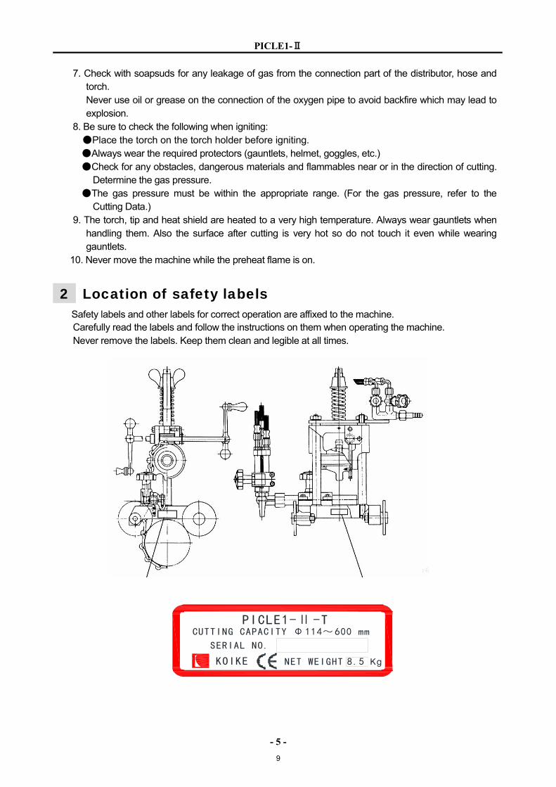
2 Location of safety labels Safety labels and other labels for correct operation are affixed to the machine. Carefully read the labels and follow the instructions on them when operating the machine. Never remove the labels. Keep them clean and legible at all times.
PICLE1-Ⅱ-TCUTTING CAPACITY Φ114~600 mm
SERIAL NO.
KOIKE NET WEIGHT 8.5 Kg
9
PICLE1-Ⅱ
- 6 -
3 Out line of machine 3.1 Features of machine
PICLE1-Ⅱ (PIPE CUTTER) is a compact pipe cutter developed on the basis of the actual conditions of installed pipelines and work site where pipe cutting is needed. The machine will exhibit excellent performance in straight and bevel cutting of all sizes of pipes, which accounts for most of pipe cutting work, being habitually used by many users.
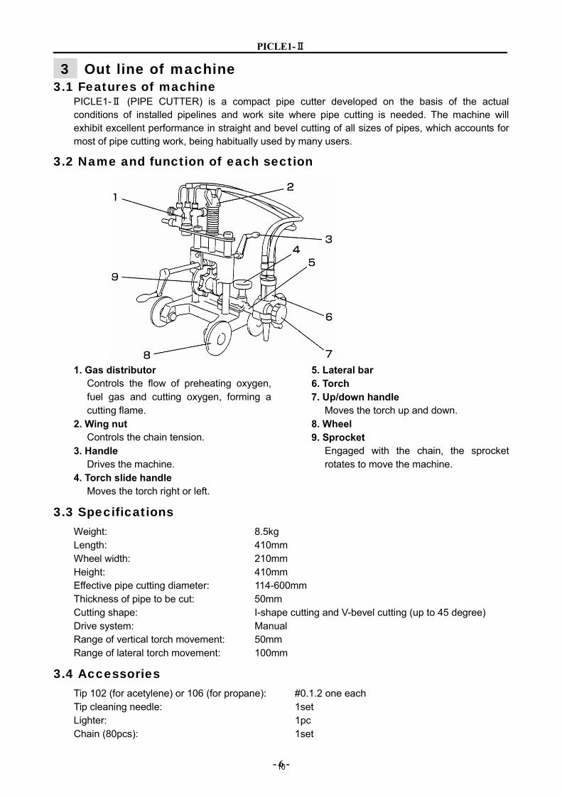
3.2 Name and function of each section
1. Gas distributor Controls the flow of preheating oxygen, fuel gas and cutting oxygen, forming a cutting flame.
2. Wing nut Controls the chain tension.
3. Handle Drives the machine.
4. Torch slide handle Moves the torch right or left.
5. Lateral bar 6. Torch 7. Up/down handle
Moves the torch up and down. 8. Wheel 9. Sprocket
Engaged with the chain, the sprocket rotates to move the machine.
3.3 Specifications Weight: 8.5kg Length: 410mm Wheel width: 210mm Height: 410mm Effective pipe cutting diameter: 114-600mm Thickness of pipe to be cut: 50mm Cutting shape: I-shape cutting and V-bevel cutting (up to 45 degree) Drive system: Manual Range of vertical torch movement: 50mm Range of lateral torch movement: 100mm
3.4 Accessories Tip 102 (for acetylene) or 106 (for propane): #0.1.2 one each Tip cleaning needle: 1set Lighter: 1pc Chain (80pcs): 1set
10
PICLE1-Ⅱ
- 7 -
4 Preparation for operation
4.1 Contents of package The contents of the standard package are shown below. Check them carefully before assembling the machine.
Body 1 set Gas distributor 1 set Torch holder 1 set Torch 1 pc Hose
Distribution hose (3 pcs set: 560L biased bend) 1 set Tip 102 (for acetylene) or 106 (for propane) #0.1.2 one each Tip cleaning needle 1 set Lighter 1 pc Chain (80 pcs) 1 set
4.2 Machine assembly 1. Carefully take the machine out of its case. 2. Carefully check that the torch holder, gas distributor, torch and etc. are in position. 3. Attach the primary hoses to the gas distributor.
Oxygen hose Gas hose
4.3 Preparation for operation
4.3.1 Gas supply hose connection 1. Connect the respective gas supply hoses to the torch and distributor. 2. Check that hoses are connected correctly and there in no gas leakage. 3. Carefully check the cutting oxygen (JO), preheating oxygen (PO), preheating gas and respective
marking before connecting hoses to the torch and distributor.
4.3.2 connecting the tip 1. select a proper tip according to the thickness of the steel plate and attach it to the torch.
(To select a tip, refer to the table of cutting data.) When fixing a tip to the torch, tighten the nut with the two wrenches attached. If the tip is tightened excessively, it will be heated during cutting and tightened still more,
making it difficult to remove the tip. In addition, avoid damaging the taper of the tip since this may causes backfire.
11
PICLE1-Ⅱ
- 8 -
4.3.3 Determination of number of chains The relationship between the pipe O.D. and the number of chain is as follows. Y=X+11 where,Y = the number of chains X = pipe O.D. (unit:cm; Round off the value in mm to the next value in cm.) For example, pipe O.D. 114.3mm 11.43cm 12 Y = X+11 = 12+11 = 23 Therefore, about 23 chains are necessary.
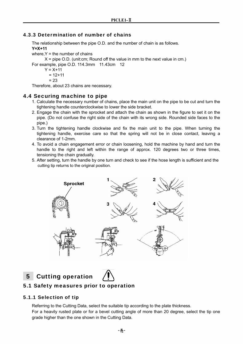
4.4 Securing machine to pipe 1. Calculate the necessary number of chains, place the main unit on the pipe to be cut and turn the
tightening handle counterclockwise to lower the side bracket. 2. Engage the chain with the sprocket and attach the chain as shown in the figure to set it on the
pipe. (Do not confuse the right side of the chain with its wrong side. Rounded side faces to the pipe.)
3. Turn the tightening handle clockwise and fix the main unit to the pipe. When turning the tightening handle, exercise care so that the spring will not be in close contact, leaving a clearance of 1-2mm.
4. To avoid a chain engagement error or chain loosening, hold the machine by hand and turn the handle to the right and left within the range of approx. 120 degrees two or three times, tensioning the chain gradually.
5. After setting, turn the handle by one turn and check to see if the hose length is sufficient and the cutting tip returns to the original position.
5 Cutting operation 5.1 Safety measures prior to operation
5.1.1 Selection of tip Referring to the Cutting Data, select the suitable tip according to the plate thickness. For a heavily rusted plate or for a bevel cutting angle of more than 20 degree, select the tip one grade higher than the one shown in the Cutting Data.
12
PICLE1-Ⅱ
- 9 -
5.2 Ignition and flame adjustment Adjust the gas pressure according to the Cutting Data. The data shows the pressure when all the valves are open. Readjust the pressure after ignition.
■Flame adjustment method
1. Open the fuel gas valve 1/4 to 1/2 a turn and light the torch with an igniter. 2. Then, open the preheating oxygen valve gradually until a white cone of the standard flame has
been obtained. (The incandescent area should be uniform and about 5-6 mm (3/16-1/14″)in length.)
3. Open the jet oxygen valve fully. Readjust the flame if its condition has changed. A disorderly flow of the jet oxygen will adversely affect the quality of the cutting surface. In such a case, clean the tip with a suitable cleaning needle while the jet oxygen is flowing.
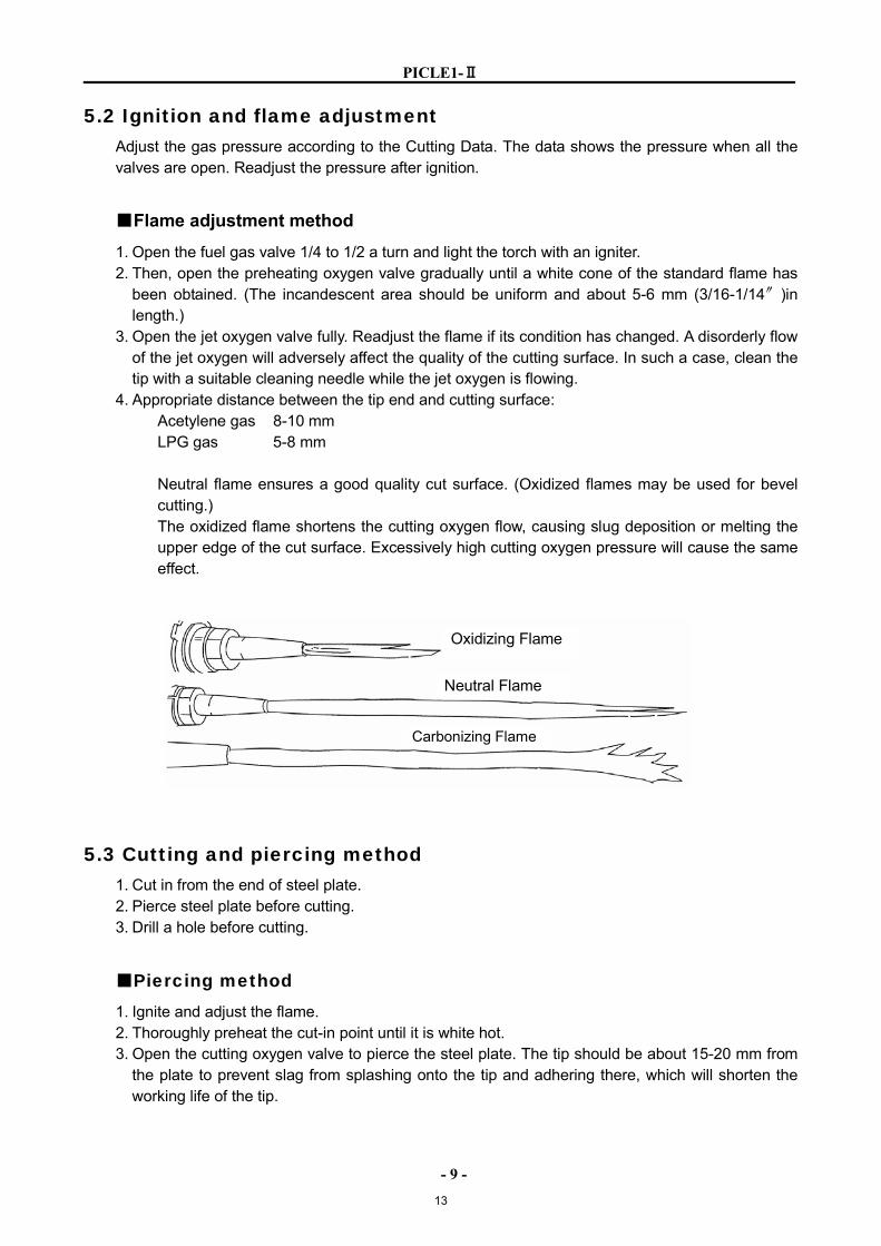
4. Appropriate distance between the tip end and cutting surface: Acetylene gas 8-10 mm LPG gas 5-8 mm Neutral flame ensures a good quality cut surface. (Oxidized flames may be used for bevel cutting.) The oxidized flame shortens the cutting oxygen flow, causing slug deposition or melting the upper edge of the cut surface. Excessively high cutting oxygen pressure will cause the same effect.
5.3 Cutting and piercing method 1. Cut in from the end of steel plate. 2. Pierce steel plate before cutting. 3. Drill a hole before cutting.
■Piercing method
1. Ignite and adjust the flame. 2. Thoroughly preheat the cut-in point until it is white hot. 3. Open the cutting oxygen valve to pierce the steel plate. The tip should be about 15-20 mm from
the plate to prevent slag from splashing onto the tip and adhering there, which will shorten the working life of the tip.
Oxidizing Flame
Carbonizing Flame
Neutral Flame
13
PICLE1-Ⅱ
- 10 -
5.4 Procedures for starting cutting operation and extinguishing the flame 1. Align the tip with the cutting start point, ignite and then adjust the flame. 2. Sufficiently preheat the cutting start point. 3. After heating, supply cutting oxygen and turn the handle simultaneously to being cutting. 4. Carefully check the cutting condition and turn the handle to set an optimum cutting speed. Refer
to the Cutting Data. 5. Extinguish the flame after cutting as follows:
1) Stop the handle. 2) Close the cutting oxygen valve. 3) Close the preheating oxygen valve. 4) Close the fuel gas valve.
5.5 Safety measures against backfire and flashback
5.5.1 Prevention of backfire Backfire may cause serious accidents or fires. Be careful to prevent such disaster. When a backfire occurs, find the cause and inspect and maintain the machine correctly before using the machine again. The following are causes of backfire:
1) Improper gas pressure adjustment. 2) Overheated tip. 3) Slag clogged in tip. 4) Damage to the tapered section of the tip or torch will cause backfire.
5.5.2 Prevention of flashback Flashback could cause fire and break the machine. Should there be a hissing sound in the torch, quickly take the following action.
1) Close the preheating oxygen valve. 2) Close the fuel gas valve. 3) Close the cutting oxygen valve.
Should flashback occur, find the cause and take appropriate action before using the machine again.
5.6 Cutting operation 1. Place the tip at the cutting start point. 2. Ignite the tip and continue preheating sufficiently. 3. Open the cutting oxygen valve and turn the handle simultaneously to begin cutting. 4. While observing the cutting conditions, turn the handle to se the optimum cutting speed. 5. After cutting, stop the handle, and close the cutting oxygen valve, preheating oxygen valve and
fuel gas valve in this order. Thereafter, repeat the operations from the beginning (item 1). During cutting, hold the wing nut with the right or left hand as shown in the figure. When the machine moves down, support the machine from the bottom, and when the machine moves up, lift the machine.
14
PICLE1-Ⅱ
- 11 -
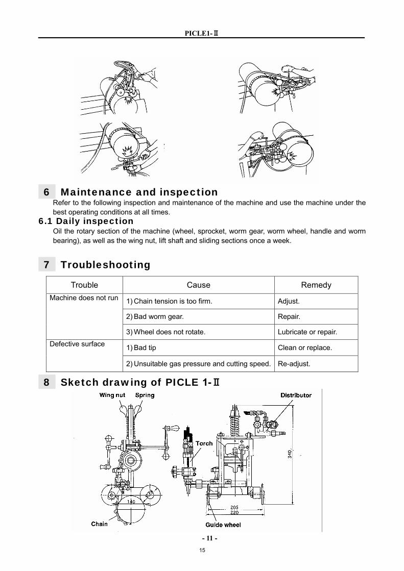
6 Maintenance and inspection Refer to the following inspection and maintenance of the machine and use the machine under the best operating conditions at all times.
6.1 Daily inspection Oil the rotary section of the machine (wheel, sprocket, worm gear, worm wheel, handle and worm bearing), as well as the wing nut, lift shaft and sliding sections once a week.
7 Troubleshooting
8 Sketch drawing of PICLE 1-Ⅱ
Trouble Cause Remedy
1) Chain tension is too firm. Adjust.
2) Bad worm gear. Repair.
Machine does not run
3) Wheel does not rotate. Lubricate or repair.
1) Bad tip Clean or replace. Defective surface
2) Unsuitable gas pressure and cutting speed. Re-adjust.
15
16
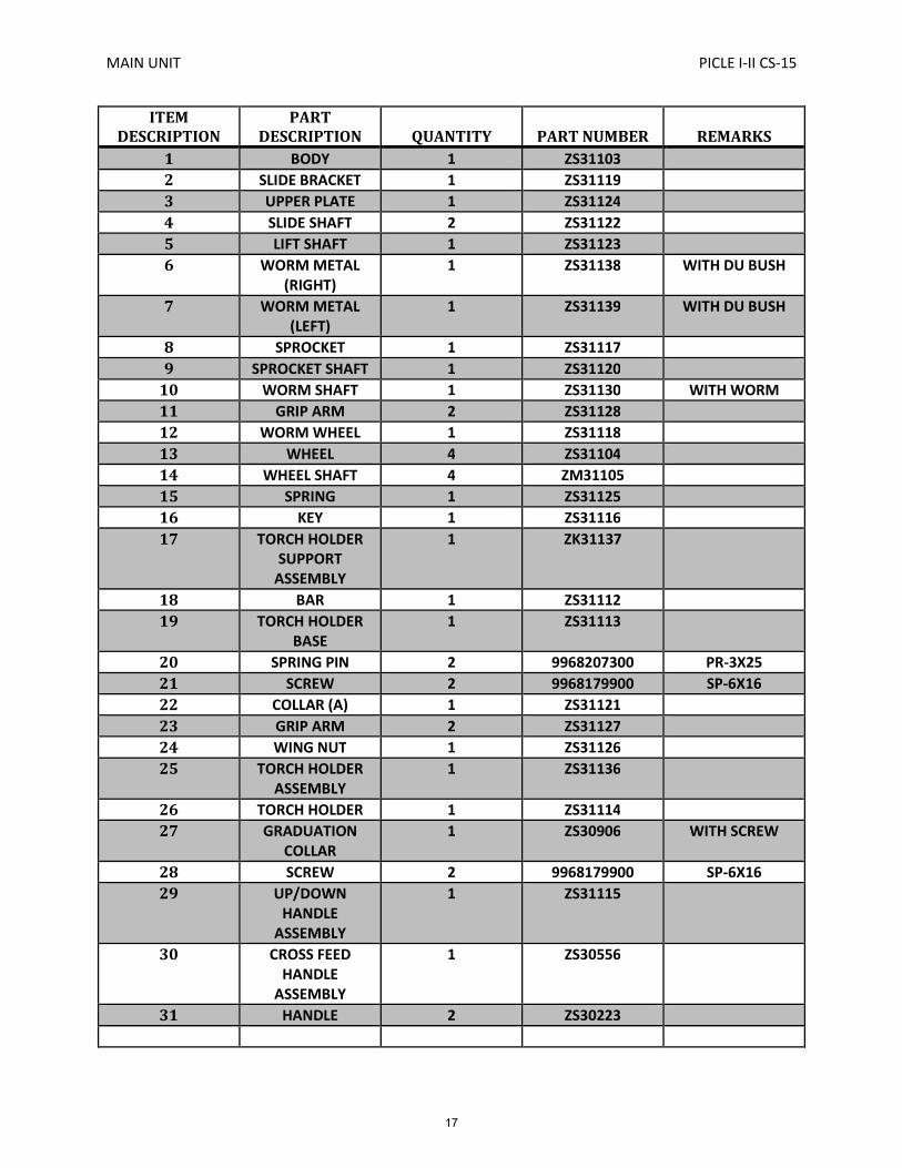
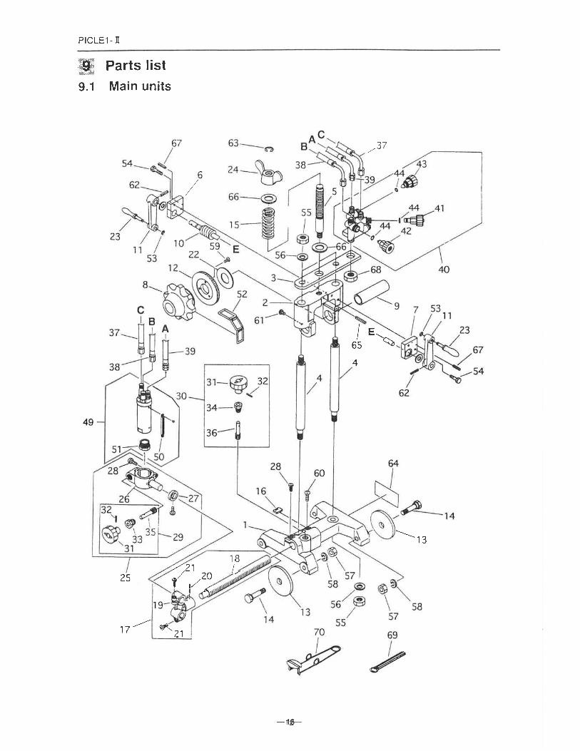
MAIN UNIT PICLE I-II CS-15
ITEMDESCRIPTION
PARTDESCRIPTION QUANTITY PART NUMBER REMARKS
1 BODY 1 ZS31103
2 SLIDE BRACKET 1 ZS31119
3 UPPER PLATE 1 ZS31124
4 SLIDE SHAFT 2 ZS31122
5 LIFT SHAFT 1 ZS31123
6 WORM METAL(RIGHT)
1 ZS31138 WITH DU BUSH
7 WORM METAL(LEFT)
1 ZS31139 WITH DU BUSH
8 SPROCKET 1 ZS31117
9 SPROCKET SHAFT 1 ZS31120
10 WORM SHAFT 1 ZS31130 WITH WORM
11 GRIP ARM 2 ZS31128
12 WORM WHEEL 1 ZS31118
13 WHEEL 4 ZS31104
14 WHEEL SHAFT 4 ZM31105
15 SPRING 1 ZS31125
16 KEY 1 ZS31116
17 TORCH HOLDERSUPPORT
ASSEMBLY
1 ZK31137
18 BAR 1 ZS31112
19 TORCH HOLDERBASE
1 ZS31113
20 SPRING PIN 2 9968207300 PR-3X25
21 SCREW 2 9968179900 SP-6X16
22 COLLAR (A) 1 ZS31121
23 GRIP ARM 2 ZS31127
24 WING NUT 1 ZS31126
25 TORCH HOLDERASSEMBLY
1 ZS31136
26 TORCH HOLDER 1 ZS31114
27 GRADUATIONCOLLAR
1 ZS30906 WITH SCREW
28 SCREW 2 9968179900 SP-6X16
29 UP/DOWNHANDLE
ASSEMBLY
1 ZS31115
30 CROSS FEEDHANDLE
ASSEMBLY
1 ZS30556
31 HANDLE 2 ZS30223
17
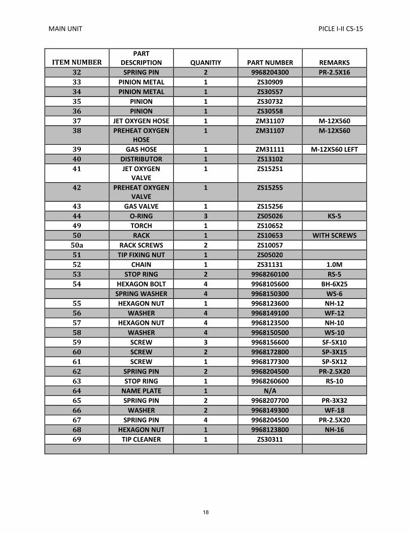
MAIN UNIT PICLE I-II CS-15
ITEM NUMBERPART
DESCRIPTION QUANITIY PART NUMBER REMARKS
32 SPRING PIN 2 9968204300 PR-2.5X16
33 PINION METAL 1 ZS30909
34 PINION METAL 1 ZS30557
35 PINION 1 ZS30732
36 PINION 1 ZS30558
37 JET OXYGEN HOSE 1 ZM31107 M-12X560
38 PREHEAT OXYGENHOSE
1 ZM31107 M-12X560
39 GAS HOSE 1 ZM31111 M-12X560 LEFT
40 DISTRIBUTOR 1 ZS13102
41 JET OXYGENVALVE
1 ZS15251
42 PREHEAT OXYGENVALVE
1 ZS15255
43 GAS VALVE 1 ZS15256
44 O-RING 3 ZS05026 KS-5
49 TORCH 1 ZS10652
50 RACK 1 ZS10653 WITH SCREWS
50a RACK SCREWS 2 ZS10057
51 TIP FIXING NUT 1 ZS05020
52 CHAIN 1 ZS31131 1.0M
53 STOP RING 2 9968260100 RS-5
54 HEXAGON BOLT 4 9968105600 BH-6X25
SPRING WASHER 4 9968150300 WS-6
55 HEXAGON NUT 1 9968123600 NH-12
56 WASHER 4 9968149100 WF-12
57 HEXAGON NUT 4 9968123500 NH-10
58 WASHER 4 9968150500 WS-10
59 SCREW 3 9968156600 SF-5X10
60 SCREW 2 9968172800 SP-3X15
61 SCREW 1 9968177300 SP-5X12
62 SPRING PIN 2 9968204500 PR-2.5X20
63 STOP RING 1 9968260600 RS-10
64 NAME PLATE 1 N/A
65 SPRING PIN 2 9968207700 PR-3X32
66 WASHER 2 9968149300 WF-18
67 SPRING PIN 4 9968204500 PR-2.5X20
68 HEXAGON NUT 1 9968123800 NH-16
69 TIP CLEANER 1 ZS30311
18
PICLE1-Ⅱ
- 15 -
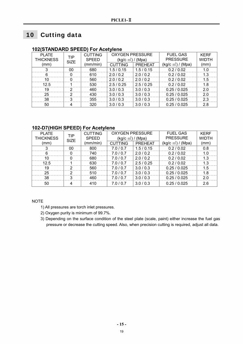
10 Cutting data
102(STANDARD SPEED) For Acetylene OXYGEN PRESSURE
(kg/c ㎡) / (Mpa) PLATE
THICKNESS (mm)
TIP SIZE
CUTTING SPEED
(mm/min) CUTTING PREHEAT
FUEL GAS PRESSURE
(kg/c ㎡) / (Mpa)
KERF WIDTH (mm)
3 00 680 1.5 / 0.15 1.5 / 0.15 0.2 / 0.02 1.0 6 0 610 2.0 / 0.2 2.0 / 0.2 0.2 / 0.02 1.3 10 0 560 2.0 / 0.2 2.0 / 0.2 0.2 / 0.02 1.5
12.5 1 530 2.5 / 0.25 2.5 / 0.25 0.2 / 0.02 1.8 19 2 460 3.0 / 0.3 3.0 / 0.3 0.25 / 0.025 2.0 25 2 430 3.0 / 0.3 3.0 / 0.3 0.25 / 0.025 2.0 38 3 355 3.0 / 0.3 3.0 / 0.3 0.25 / 0.025 2.3 50 4 320 3.0 / 0.3 3.0 / 0.3 0.25 / 0.025 2.8
102-D7(HIGH SPEED) For Acetylene OXYGEN PRESSURE
(kg/c ㎡) / (Mpa) PLATE
THICKNESS (mm)
TIP SIZE
CUTTING SPEED
(mm/min) CUTTING PREHEAT
FUEL GAS PRESSURE
(kg/c ㎡) / (Mpa)
KERF WIDTH (mm)
3 00 800 7.0 / 0.7 1.5 / 0.15 0.2 / 0.02 0.8 6 0 740 7.0 / 0.7 2.0 / 0.2 0.2 / 0.02 1.0 10 0 680 7.0 / 0.7 2.0 / 0.2 0.2 / 0.02 1.3
12.5 1 630 7.0 / 0.7 2.5 / 0.25 0.2 / 0.02 1.3 19 2 560 7.0 / 0.7 3.0 / 0.3 0.25 / 0.025 1.5 25 2 510 7.0 / 0.7 3.0 / 0.3 0.25 / 0.025 1.8 38 3 460 7.0 / 0.7 3.0 / 0.3 0.25 / 0.025 2.0 50 4 410 7.0 / 0.7 3.0 / 0.3 0.25 / 0.025 2.6
NOTE
1) All pressures are torch inlet pressures.
2) Oxygen purity is minimum of 99.7%.
3) Depending on the surface condition of the steel plate (scale, paint) either increase the fuel gas
pressure or decrease the cutting speed. Also, when precision cutting is required, adjust all data.
19
PICLE1-Ⅱ
- 16 -
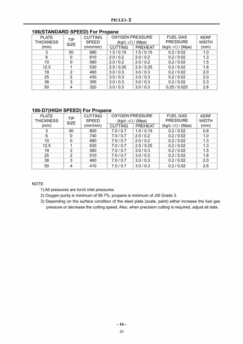
106(STANDARD SPEED) For Propane OXYGEN PRESSURE
(kg/c ㎡) / (Mpa) PLATE
THICKNESS (mm)
TIP SIZE
CUTTING SPEED
(mm/min) CUTTING PREHEAT
FUEL GAS PRESSURE
(kg/c ㎡) / (Mpa)
KERF WIDTH (mm)
3 00 680 1.5 / 0.15 1.5 / 0.15 0.2 / 0.02 1.0 6 0 610 2.0 / 0.2 2.0 / 0.2 0.2 / 0.02 1.3 10 0 560 2.0 / 0.2 2.0 / 0.2 0.2 / 0.02 1.5
12.5 1 530 2.5 / 0.25 2.5 / 0.25 0.2 / 0.02 1.8 19 2 460 3.0 / 0.3 3.0 / 0.3 0.2 / 0.02 2.0 25 2 430 3.0 / 0.3 3.0 / 0.3 0.2 / 0.02 2.0 38 3 355 3.0 / 0.3 3.0 / 0.3 0.2 / 0.02 2.3 50 4 320 3.0 / 0.3 3.0 / 0.3 0.25 / 0.025 2.8
106-D7(HIGH SPEED) For Propane OXYGEN PRESSURE
(kg/c ㎡) / (Mpa) PLATE
THICKNESS (mm)
TIP SIZE
CUTTING SPEED
(mm/min) CUTTING PREHEAT
FUEL GAS PRESSURE
(kg/c ㎡) / (Mpa)
KERF WIDTH (mm)
3 00 800 7.0 / 0.7 1.5 / 0.15 0.2 / 0.02 0.8 6 0 740 7.0 / 0.7 2.0 / 0.2 0.2 / 0.02 1.0 10 0 680 7.0 / 0.7 2.0 / 0.2 0.2 / 0.02 1.3
12.5 1 630 7.0 / 0.7 2.5 / 0.25 0.2 / 0.02 1.3 19 2 560 7.0 / 0.7 3.0 / 0.3 0.2 / 0.02 1.5 25 2 510 7.0 / 0.7 3.0 / 0.3 0.2 / 0.02 1.8 38 3 460 7.0 / 0.7 3.0 / 0.3 0.2 / 0.02 2.0 50 4 410 7.0 / 0.7 3.0 / 0.3 0.2 / 0.02 2.6
NOTE
1) All pressures are torch inlet pressures.
2) Oxygen purity is minimum of 99.7%, propane is minimum of JIS Grade 3.
3) Depending on the surface condition of the steel plate (scale, paint) either increase the fuel gas
pressure or decrease the cutting speed. Also, when precision cutting is required, adjust all data.
20

PICLE1-Ⅱ
Operation Manual - Version T89001732
2015-04-18
24