Embed Size (px)
Citation preview
1
READ THIS MANUAL CAREFULLY BEFORE USING YOUR PORTABLE AIR CONDITIONER AND KEEP IT FOR FUTURE REFERENCE.
Model NPPAC12HKM
Portable Air Conditioner12000 BTU
User’s Manual

2
PRODUCT REGISTRATIONThank you for purchasing a Norpole™ product. The first step to protect your new product is to complete the product registration on our website: www.mcappliance.com/register. The benefits of registering your product include the following:
1. Registering your product will allow us to contact you regarding a safety notification or product update.2. Registering your product will allow for more efficient warranty service processing when warranty service is
required.3. Registering your product could act as your proof of purchase in the event of insurance loss.
Once again, thank you for purchasing a Norpole product.

3
CONTENTSPRODUCT REGISTRATION . . . . . . . . . . . . . . . . . . . . . . . . . . . . . . . . . . . . . . . 2IMPORTANT SAFETY INSTRUCTIONS . . . . . . . . . . . . . . . . . . . . . . . . . . . . . . 4SPECIFICATIONS. . . . . . . . . . . . . . . . . . . . . . . . . . . . . . . . . . . . . . . . . . . . . . . 6PARTS IDENTIFICATION . . . . . . . . . . . . . . . . . . . . . . . . . . . . . . . . . . . . . . . . . 7INSTALLATION INSTRUCTIONS . . . . . . . . . . . . . . . . . . . . . . . . . . . . . . . . . . . 8REMOTE CONTROL . . . . . . . . . . . . . . . . . . . . . . . . . . . . . . . . . . . . . . . . . . . 13OPERATION INSTRUCTIONS . . . . . . . . . . . . . . . . . . . . . . . . . . . . . . . . . . . . 15CARE AND MAINTENANCE. . . . . . . . . . . . . . . . . . . . . . . . . . . . . . . . . . . . . . 19TROUBLESHOOTING . . . . . . . . . . . . . . . . . . . . . . . . . . . . . . . . . . . . . . . . . . 20 LIMITED WARRANTY. . . . . . . . . . . . . . . . . . . . . . . . . . . . . . . . . . . . . . . . . . . 21

4
IMPORTANT SAFETY INSTRUCTIONSExPLANATION OF SYMBOLS
WARNING: Hazards or unsafe practices which COULD result in severe personal injury or death. CAUTION: Hazards or unsafe practices which COULD result in minor personal injury or property damage.
IMPORTANT SAFETY INSTRUCTIONS 1. Read all instructions before using the appliance.2. WARNING: To prevent injuries or property damage, the following instructions must be followed. 3. This appliance should not be operated, cleaned or maintained by anyone that is not able to follow
proper safety procedures or does not have experience with this type of equipment, unless under close supervision.
4. WARNING: DO NOT use in an area where it may be exposed to combustible gases or liquids, as this may cause a fire.
5. CAUTION: Installation must be performed according to the installation instructions and ALWAYS use the correct tools as specified. Use only accessories and parts included with the appliance. Improper installation can cause water leakage, electrical shock, or fire.
6. Place the unit on a level, sturdy section of the floor, away from heat sources or anywhere it could get wet.
7. DO NOT operate in a wet environment, such as a bathroom or laundry room.8. DO NOT stand, sit, or place anything on top of the unit.9. DO NOT let children operate or play on or around the air conditioner. Children should be supervised
around the unit at all times.10. CAUTION: The power cord is equipped with a 3-prong grounding plug to protect against shock
hazards. ALWAYS plug cord into a properly installed and grounded 3-prong wall receptacle. Refer to the manufactures rating label for electrical and other technical data specific to this unit.
11. DO NOT modify or cut the power cord, or use any other cord or plug. If the cord or plug is damaged, DO NOT use. Contact customer service or a qualified service technician for replacement or repair.
12. DO NOT run cord under carpeting, throw rugs, runners, or similar coverings. DO NOT route cord under furniture, appliances, or any heavy object. Place the cord where it will not be tripped over.
13. DO NOT start or stop the unit by turning the power on or off.14. DO NOT insert or pull out the plug with wet hands.15. DO NOT use this item on a solid state speed control device (such as a fan control wall switch).16. DO NOT obstruct the unit to ensure proper function and safety.17. DO NOT insert your finger or other foreign objects into grills or openings. 18. CAUTION: ALWAYS turn off and unplug the unit prior to cleaning or maintenance.19. Contact customer service or an authorized service technician for repair or maintenance of this unit.
DO NOT try to take apart or repair the unit by yourself.20. Turn off and unplug the unit if strange sounds, smells, or smoke come from it.

5
21. If the appliance is knocked over during use, turn off the unit and unplug it immediately. Visually inspect the unit to ensure there is no damage. If there is any damage, or you suspect the unit has been damaged, contact a technician or customer service for assistance.
22. If water spills into the unit, turn it off, unplug it, and contact a qualified service technician.23. DO NOT try to move the unit when the tank is full, or force the castors to roll on carpet. Doing so
may cause the unit to tip over and spill water.24. ALWAYS insert the filters securely. Clean filter once every two weeks.
READ AND FOLLOW THISSAFETY INFORMATION CAREFULLY
SAVE THESE INSTRUCTIONS
6
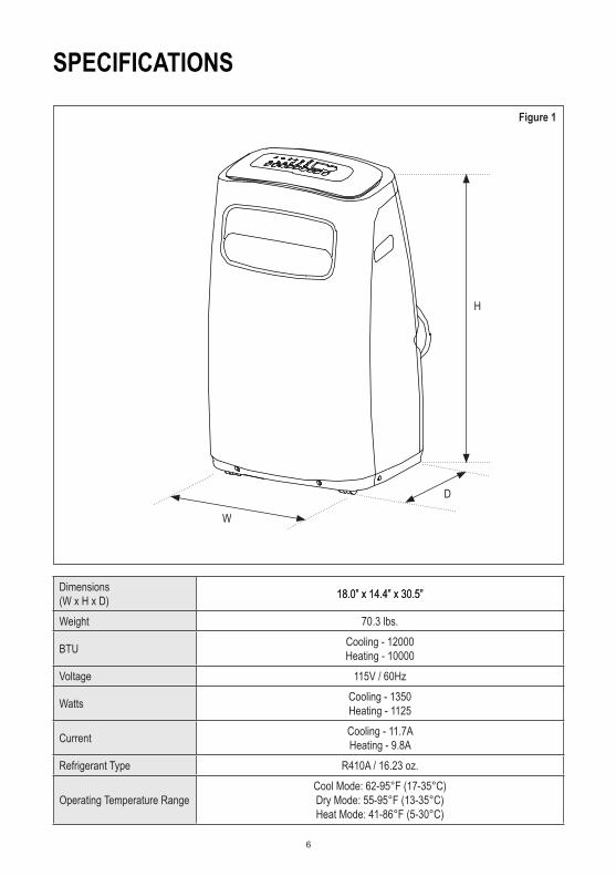
SPECIFICATIONS
Dimensions(W x H x D)Weight
BTU Cooling - 12000Heating - 10000
Voltage 115V / 60Hz
Watts Cooling - 1350Heating - 1125
Current Heating - 9.8ARefrigerant Type R410A / 16.23 oz.
Operating Temperature RangeCool Mode: 62-95°F (17-35°C)Dry Mode: 55-95°F (13-35°C)Heat Mode: 41-86°F (5-30°C)
H
W
D
Figure 1
Cooling - 11.7A
18.0” x 14.4” x 30.5”18.0” x 14.4” x 30.5”
7
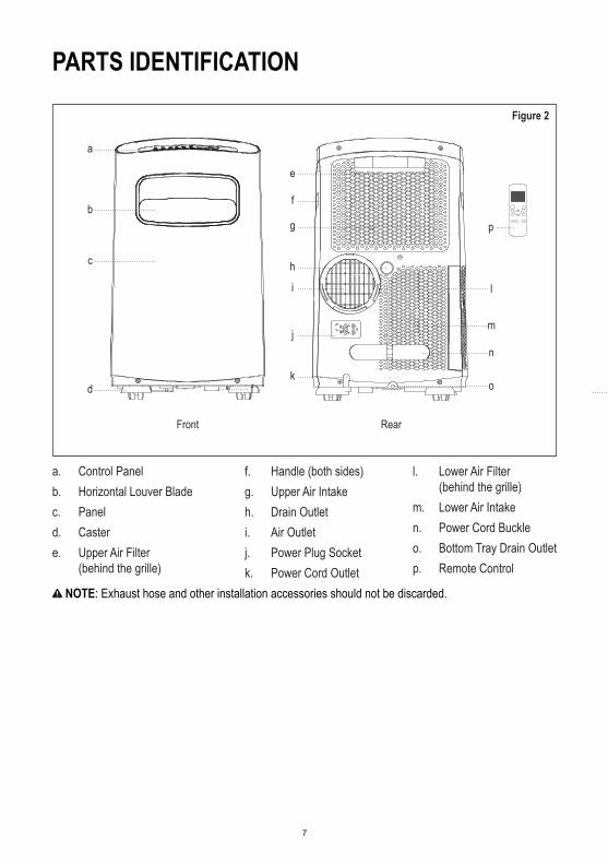
PARTS IDENTIFICATION
a. Control Panelb. Horizontal Louver Bladec. Paneld. Castere. Upper Air Filter (behind the grille)
f. Handle (both sides)g. Upper Air Intakeh. Drain Outleti. Air Outletj. Power Plug Socketk. Power Cord Outlet
l. Lower Air Filter (behind the grille)m. Lower Air Intaken. Power Cord Buckleo. Bottom Tray Drain Outletp. Remote Control
NOTE: Exhaust hose and other installation accessories should not be discarded.
Figure 2
p
e
f
g
h
i
j
k
l
o
n
m
a
b
c
d f
Front Rear
8
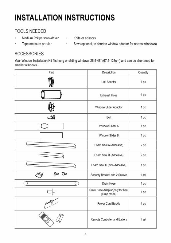
INSTALLATION INSTRUCTIONSTOOLS NEEDED• Medium Philips screwdriver• Tape measure or ruler
ACCESSORIESYour Window Installation Kit fits hung or sliding windows 26.5-48” (67.5-123cm) and can be shortened for smaller windows.
Part Description Quantity
Unit Adaptor 1 pc
Exhaust Hose 1 pc
Window Slider Adaptor 1 pc
Bolt 1 pc
Window Slider A 1 pc
Window Slider B 1 pc
Foam Seal A (Adhesive) 2 pc
Foam Seal B (Adhesive) 2 pc
Foam Seal C (Non-Adhesive) 1 pc
Security Bracket and 2 Screws 1 set
Drain Hose 1 pc
Drain Hose Adaptor(only for heat pump mode) 1 pc
Power Cord Buckle 1 pc
Remote Controller and Battery 1 set
• Knife or scissors• Saw (optional, to shorten window adaptor for narrow windows)

9
Figure 4
Figure 3
Figure 5
Figure 6
LOCATION Your installation location should meet the following requirements:• Make sure that you install your unit on a level surface to
minimize noise and vibration.• The unit must be installed near a grounded plug, and the
Collection Tray Drain (found on the back of the unit) must be accessible.
• The unit should be located at least 12” (30cm) from the nearest wall to ensure proper air conditioning.
• DO NOT cover the Intakes, Outlets or Remote Signal Receptor of the unit, as this could cause damage to the unit.
WINDOW INSTALLATION KIT 1. Preparing the Exhaust Hose Assembly:
Press the exhaust hose into the window slider adaptor and unit adaptor and clamp with the buckles of the adaptor.
2. Attach the Exhaust Hose Assembly to the Unit: Align the hook on the Unit Adaptor with the Hole Seat on the back of the unit and insert into lower groove, then attach Hook to the Hole Seat.
3. Prepare the Adjustable Window Slider: Measure the size of your window opening. If needed, cut the window slider to the correct length. You may need both window sliders, in which case, slide Window Slider B into Window Slider A, adjust to correct size, and use the bolt to fasten the window sliders together.
INSTALLTION NOTE: Once the Exhaust Hose Assembly and Adjustable Window Slider are prepared, install according
to the type of window you are using.
Type 1: Hung Window Installation
1
Foam seal B(Adhesive type-shorter)
Foam seal A(Adhesive type)
Cut the adhesive foam seal A and B strips to the proper lengths, and attach them to the window sash and frame as shown.
Exhaust Hose Exhaust Hose Assembly
Unit Adaptor
Hook
Adaptor Lower Groove
Make sure the adaptor is inserted into the lower groove of the air outlet.
Hole Seat
Bolt
WindowSlider B
WindowSlider A
Window Slider Adaptor

10
2Window Slider A
Window Slider B(if required)
Insert the window slider assembly into the window opening.
3
Foam seal C(Non-adhesive type)
Cut the non-adhesive foam seal C strip to match the width of the window. Insert the seal between the glass and the window frame to prevent air and insects from getting into the room.
4
2 Screws
Security BracketIf desired, install the security bracket with 2 screws as shown.
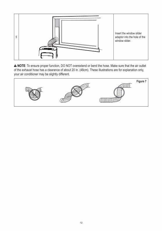
5Insert the window slider adaptor into the hole of the window slider.

11
Type 2: Sliding Window Installation
1
Foam seal B(Adhesive type-shorter)
Foam seal A(Adhesive type)
Cut the adhesive foam seal A and B strips to the proper lengths, and attach them to the window sash and frame as shown.
2
Window Slider A
Window Slider B(if required) Insert the window slider
assembly into the window opening.
3
Foam seal C(Non-adhesive type)
Cut the non-adhesive foam seal C strip to match the window height. Insert the foam seal between the glass and the window frame to prevent air and insects from getting into the room.
4
2 Screws
Security Bracket If desired, install the
security bracket with 2 screws as shown.
12
5Insert the window slider adaptor into the hole of the window slider.
NOTE: To ensure proper function, DO NOT overextend or bend the hose. Make sure that the air outlet of the exhaust hose has a clearance of about 20 in. (48cm). These illustrations are for explanation only, your air conditioner may be slightly different.
Figure 7

13
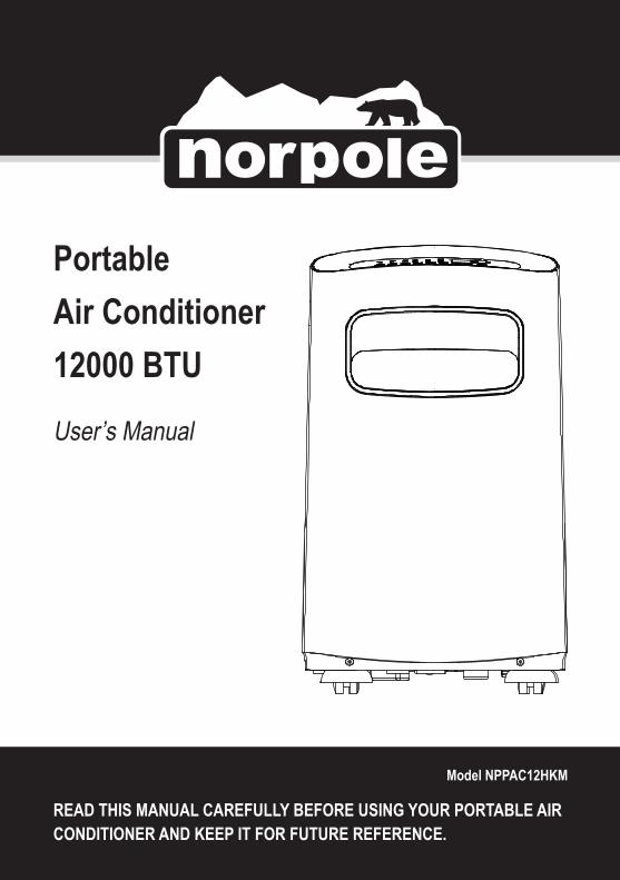
Figure 8
REMOTE CONTROLBefore you begin using your new air conditioner, make sure to familiarize yourself with the remote control. The following is a brief introduction to the remote control itself. For instructions on how to operate your air conditioner, refer to the OPERATING INSTRUCTIONS section of this manual. For best results, make sure you are pointing the remote control at the air conditioner. The remote has a range of about 26’ (8m), and there will be a beep from the A/C unit when the remote signal is received. Anything obstructing a direct line between the remote and the unit, as well as direct sunlight, may interfere with the signal.
FUNCTION BUTTONS• Button designs on your unit may differ slightly from the example shown. If the unit does not have a
particular function, pressing that function button on the remote control will have no effect.• See OPERATING INSTRUCTIONS section for more detailed information on the functions controlled
by the remote control. a. ON/OFF: Turns the unit on and off.b. MODE: Cycles through the modesc. FAN: Changes the fan speedd. SLEEP: Starts the sleep modee. SWING: Starts and stops louversf. TEMP: Adjusts temperature up or down. Pressing up and down arrows together for 3 sec will change display from F to C.g. SHORT CUT: Sets and activates pre-sets
• Used to save the current settings or resume previous settings.• Push for more than 2 seconds, the system will automatically save the current operation settings including operating mode, setting temperature, fan speed level and sleep feature (if activated ).
af
g
hijk
b
c
de
• Push this button when unit is on and the system will automatically restore the saved settings including operating mode, setting temperature, fan speed level and sleep feature (if activated).
h. TIMER ON/OFF: Sets timer to turn unit on or off.i. LED: Turns units LED Display on or off.
REMOTE CONTROL DISPLAYa. Transmission Indicator: Lights up when remote sends signal to unit.b. ON/OFF Display: Appears when the unit is turned on, and disappears when it is turned off.c. TIMER ON Display: Displays when TIMER ON is set.

14
Figure 9
i. Temperature/Timer Display: Displays the set temperature by default, or timer setting when using TIMER ON/OFF functions. This display is blank when operating in FAN Mode.
• Temperature Range: 62°F – 86°F (17°C - 30°C)• Timer Setting Range: 0 – 24 hours
INSERTING AND REPLACING BATTERIESYour remote uses two AAA batteries. To install or replace batteries: 1. Slide the cover on the back of the remote downward, exposing the battery compartment.2. Insert the batteries, making sure the (+) and (-) ends of the batteries match the symbols inside the
battery compartment.3. Slide the battery cover back into place.
NOTE: For optimum performance, do not mix old and new batteries. It is recommended to remove the batteries if the remote will not be used for more than 2 months. Always be sure to properly dispose of old batteries.
The device complies with the local national regulations. In Canada, it complies with CAN ICES-3(B)/NMB-3(B). In the USA, this device complies with part 15 of the FCC Rules. Operation is subject to the following two conditions: (1) This device may not cause harmful interference, and (2) this device must accept any interference received, including interference that may cause undesired operation.This equipment has been tested and found to comply with the limits for a Class B digital device, pursuant to part 15 of the FCC Rules. These limits are designed to provide reasonable protection against harmful interference in a residential installation. This equipment generates, uses and can radiate radio frequency energy and, if not installed and used in accordance with the instructions, may cause harmful interference to radio communications. However, there is no guarantee that interference will not occur in a particular installation. If this equipment does cause harmful interference to radio or television reception, which can be determined by turning the equipment off and on, the user is encouraged to try to correct the interference by one or more of the following measures: • Reorient or relocate the receiving antenna.• Increase the separation between the equipment and receiver.• Connect the equipment into an outlet on a circuit different from that to which the receiver is connected.• Consult the dealer or an experienced radio/TV technician for help.Changes or modifications not approved by the party responsible for compliance could void user’s authority to operate the equipment.
d. TIMER OFF Display: Displays when TIMER OFF is set.e. Mode Display: Displays the mode “AUTO” – “COOL” – “DRY” – “HEAT” – “FAN”.f. Battery Display: Low Battery detectiong. Sleep Display: Displays when Sleep function is activated.h. Fan Speed Display: Displays selected Fan Speed “>>>>>>>>>>” (HIGH) – “>>>>>>>” (MED) – “>>>” (LOW). This display is blank when set to AUTO speed.
a b dc
e
f
g
h
i
15
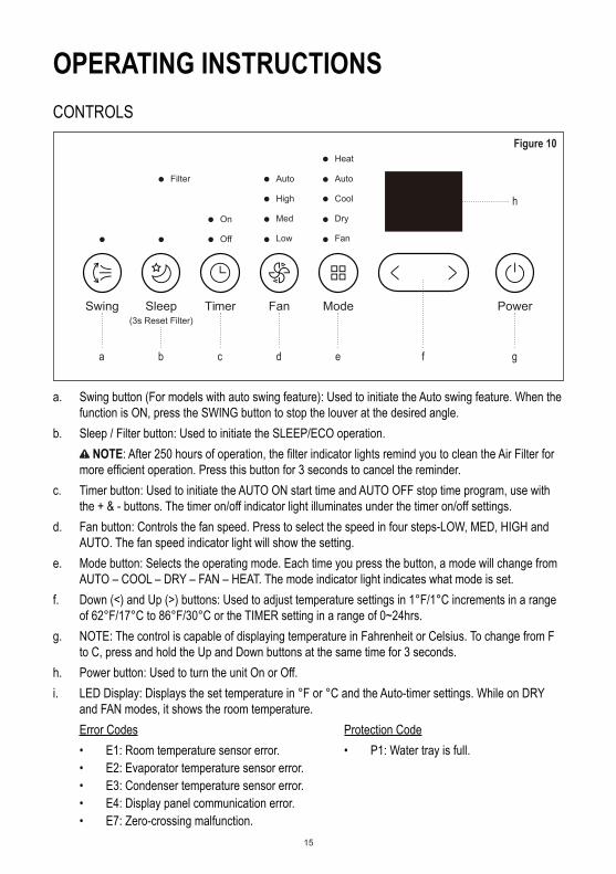
OPERATING INSTRUCTIONSCONTROLS
Figure 10
a. Swing button (For models with auto swing feature): Used to initiate the Auto swing feature. When the function is ON, press the SWING button to stop the louver at the desired angle.
b. Sleep / Filter button: Used to initiate the SLEEP/ECO operation. NOTE: After 250 hours of operation, the filter indicator lights remind you to clean the Air Filter for
more efficient operation. Press this button for 3 seconds to cancel the reminder.c. Timer button: Used to initiate the AUTO ON start time and AUTO OFF stop time program, use with
the + & - buttons. The timer on/off indicator light illuminates under the timer on/off settings.d. Fan button: Controls the fan speed. Press to select the speed in four steps-LOW, MED, HIGH and
AUTO. The fan speed indicator light will show the setting.e. Mode button: Selects the operating mode. Each time you press the button, a mode will change from
AUTO – COOL – DRY – FAN – HEAT. The mode indicator light indicates what mode is set.f. Down (<) and Up (>) buttons: Used to adjust temperature settings in 1°F/1°C increments in a range
of 62°F/17°C to 86°F/30°C or the TIMER setting in a range of 0~24hrs.g. NOTE: The control is capable of displaying temperature in Fahrenheit or Celsius. To change from F
to C, press and hold the Up and Down buttons at the same time for 3 seconds.h. Power button: Used to turn the unit On or Off.i. LED Display: Displays the set temperature in °F or °C and the Auto-timer settings. While on DRY
and FAN modes, it shows the room temperature.
Filter Auto
High
Med
Low
Auto
Heat
Cool
Dry
Fan
On
Off
Swing Sleep(3s Reset Filter)
Timer Fan Mode Power
a b c d e f
h
g
Error Codes• E1: Room temperature sensor error. • E2: Evaporator temperature sensor error.• E3: Condenser temperature sensor error.• E4: Display panel communication error.• E7: Zero-crossing malfunction.
Protection Code• P1: Water tray is full.

16
OPERATING Cool Mode• Press the “MODE” button until the “COOL” indicator lights.• Press the ADJUST buttons “+” or “-” to select your desired room temperature. The temperature can
be set within a range of 62°F~86°F /17°C~30°C.• Press the “FAN SPEED” button to choose the fan speed.
Heat Mode• Press the “MODE” button until the “HEAT” indicator lights.• Press the ADJUST buttons “+” or “- “to select your desired room temperature. The temperature can
be set within a range of 62°F~86°F (17°C~30°C).• Press the “FAN SPEED” button to choose the fan speed. For some models, the fan speed cannot be
adjusted under HEAT mode.
Dry Mode• Press the “MODE” button until the “DRY” indicator lights.• The fan motor operates at LOW speed and cannot be changed. You cannot adjust the temperature
in this mode.• Keep windows and doors closed and do not run the exhaust duct to window.
Auto Mode• Press the “MODE” button until the “AUTO” indicator lights.• When in AUTO mode, cooling, heating (if applicable), or fan only will be automatically selected to
maintain the room temperature the unit is set for.• When in AUTO mode, fan speed cannot be changed.
Fan Mode• Press the “MODE” button until the “FAN” indicator lights.• Press the “FAN SPEED” button to choose the fan speed. The temperature cannot be adjusted.• Do not run the exhaust duct to window.
Timer Mode• If the unit is on, pressing the Timer button once will start the Auto-Off stop program, and the Off • indicator light above the timer button will be lit. Pushing the Timer button again within 5 seconds will
switch to the Auto-On start function, and the On indicator will be lit.• If the unit is off, pushing Timer will start the Auto-On start feature, and pushing it again within 5
seconds will switch it to the Auto-Off stop feature. • Press or hold the UP or DOWN button to set the Auto time in 0.5 hour increments, up to 10 hours,
then in 1 hour increments up to 24 hours. The control will count down the time remaining until starting or stopping.
NOTE: If the display shows one of the above codes turn off and unplug the unit, and check for any obstructions or empty the water tray, then restart. If code is still present, turn off again and unplug, and contact customer service or service technician for assistance.

17
NOTE: The Timer feature counts down the time set for On or Off. For example, if it is currently 1:30pm, setting the unit to Timer On for 4 hours will set the unit to turn on at 5:30pm.
• The system will automatically revert back to display the previous temperature setting if no button is pressed within 5 seconds.
• Turning the unit ON or OFF at any time or adjusting the timer setting to 0.0 will cancel the Auto Start/Stop timer program.
• If a malfunction occurs, the Auto Start/Stop program will be cancelled. NOTE: When using the Remote Control to set Timer Mode, push the TIMER ON or TIMER OFF buttons
to adjust the time in 0.5 hour increments, up to 10 hours, then in 1 hour increments up to 24 hours. To set both an Auto-On and Auto-Off timers, first set the Timer On to the desired length of time, wait 3 seconds, then set the desired Timer Off using the corresponding buttons.
Sleep/Eco Mode• Pressing the Sleep button in COOL mode will allow the set temperature to increase by 2°F / 1°C
after 30 minutes, and again after another 30 minutes. If unit is in HEAT mode, the set temperature will decrease the same amount in the same time. The unit will maintain the new temperature for 7 hours, and then return to the previously selected temperature setting.
NOTE: This feature is not available in FAN or DRY mode.
Other Features • Air Flow Direction Adjustment: When the unit is turned On, the louver opens fully. Press the SWING
button on the control panel or remote control to move the louver up and down automatically. NOTE: On units that have the SWING feature, DO NOT adjust the louver manually. NOTE: When using the Remote Control, each time the Swing button is pushed, the angle of the
louvers adjust 6 degrees. Push and hold Swing button for about 2 seconds to activate the auto-swing feature.
• Auto-Restart: If the power to the unit is unexpectedly lost or shut off, the unit will maintain previous settings when it is restored.
• 3 Minute Delay: When the unit is stopped, shut off, or loses power, it cannot be restarted for 3 minutes to protect the cooling system. Operation will automatically start after 3 minutes.
DRAINING THE WATER There are two ways to remove water collected while the unit is running. 1. Manually empty the water bucket: When the water level of
the bottom tray reaches a predetermined level, the unit beeps 8 times and the display will show “P1”. The air conditioning / dehumidification process will immediately stop, however the fan motor will continue to run (this is normal). Turn off and unplug the unit, carefully move it to a drain location, remove the bottom drain plug and let the water drain out. Reinstall the bottom drain plug and restart the unit until the “P1” symbol disappears. If the error repeats, call for service.
NOTE: Be sure to reinstall the bottom drain plug firmly to prevent leakage before using the unit.
Figure 11
Remove thebottom drain plug.

18
2. Continuous Draining: To drain continuously to a floor drain, connect the drain connector (5/8” universal female mender) to the drain hose. Make sure the connection is tight and there is no leak and place the open end of the hose directly over the drain in your basement floor. The water hose should slope downward to allow the water to flow out smoothly.
Figure 12Remove the upper drain
plug.
Continuous Drain Hose
Press the power cord buckle into the rear cover.

19
CARE AND MAINTENANCE WARNING: Turn the unit off and remove the plug from the wall outlet before maintenance or cleaning.
• DO NOT use flammable liquids or chemicals to clean the unit.• DO NOT immerse in or spray with water to clean.• DO NOT operate the unit if the power cord is damaged.• The water bucket should be cleaned every few weeks or as needed. DO NOT leave water in the
bucket when unit is not being used. ALWAYS empty before storage or as soon as “P1” is displayed.
CLEAN THE AIR FILTERS• Clean the air filters with water
at least once every 2 weeks for optimal performance, or as needed. DO NOT use the unit with the filters missing.
• If used in a household with animals, periodically wipe down the grills to prevent animal fur from blocking airflow.
Figure 13
CLEANING THE PORTABLE AIR CONDITIONER• Clean the unit using a damp, lint-free cloth and mild detergent (if needed) and dry off with a dry,
lint-free cloth.
STORAGE• Drain the unit’s water collection tray according to the instructions.• Run the unit on FAN mode for 12 hours in a warm room to dry it and prevent mold. Turn off the
appliance and unplug it. Clean the air filter according to the instructions above. Reinstall the clean, dry filter before storing.
• Remove the batteries from the remote control.• Be sure to store the unit in a cool, dark place. Exposure to direct sunshine or extreme heat can
shorten the lifespan of the unit.
Upper Filter (Take out.)
Lower Filter B (Take out.)
Lower Filter A (Press the grill down slightly and pull the lower filter A out at the same time.)

20
TROUBLESHOOTING Please check the following before calling for service.
Problem Possible Cause Troubleshooting
Unit does not turn on when pressing ON/OFF button.
P1 Error CodeThe Water Collection Tray is full.Turn off and unplug the unit, drain the water from the Water Collection Tray and restart the unit.
In COOL mode: Room temperature is lower than the set temperature. Reset the temperature.
Unit does not cool Well.
The air filter is blocked or dirty. Turn off the unit and clean the filter according to instructions.
Exhaust hose is not connected or is blocked.
Turn off the unit, disconnect the hose, check for blockage and reconnect the hose.
The unit is low on Refrigerant. Call customer service or service technician.Temperature setting is too High. Decrease the set temperature.Windows or doors in room are open. Make sure all windows and doors are closed.The room area is too large. Double-check the cooling area.There are heat sources inside the room. Remove the heat sources if possible.
The unit is noisy and vibrates too much.
The ground or the unit is not level Place the unit on a flat, level surface, make sure unit is level.
The air filter is blocked or dirty. Turn off the unit and clean the filter according to instructions.
The unit makes a gurgling sound.
This sound is caused by the flow of refrigerant inside the unit. This is normal.

21
LIMITED WARRANTYNorpole, Inc. warrants each new PORTABLE AIR CONDITIONER to be free from defects in material and workmanship and agrees to remedy any such defect or to furnish a new part(s) (at the company’s option) for any part(s) of the unit that has failed during the warranty period. Parts and labor expenses are covered on this unit for a period of one year from the date of purchase. In addition, Norpole, Inc. warrants the compressor (parts only) to be free from defects in material and workmanship for a period of 5 years. The consumer is responsible for all labor and transportation expenses related to the diagnosis and replacement of the compressor after the initial one-year warranty expires. In the event that the unit requires replacement or refund under the terms of this warranty, the consumer is responsible for all transportation expenses to return the unit to our factory prior to receiving a replacement unit or refund. A refund or replacement will be issued at the discretion of Norpole, Inc.. A copy of the dated sales receipt/invoice is required to receive warranty service or a refund.This warranty covers appliances in use within the contiguous United States, Alaska, Hawaii and Puerto Rico. The warranty does not cover the following:
• Damages due to shipping damage or improper installation.• Damages due to misuse or abuse.• Content losses due to failure of the unit.• Inside components such as the filter, etc.• Repairs performed by unauthorized service agents.• Service calls that do not involve defects in material and workmanship, such as instructions on proper use of
the product or improper installation.• Replacement or resetting of house fuses or circuit breakers.• Failure of this product if used for purposes other than its intended purpose.• Disposal costs for any failed unit not returned to our factory.• Any delivery or installation costs incurred as the result of a unit that fails to perform as specified.• Expenses for travel and transportation for product service if your appliance is located in a remote area
where service by an authorized service technician is not available.• The removal and reinstallation of your appliance if it is installed in an inaccessible location or is not installed
in accordance with published installation instructions.• Refunds for non-repairable products are limited to the price paid for the unit per the sales receipt.• This warranty is non-transferable. This warranty applies only to the original purchaser and does not extend
to any subsequent owners.
LIMITATIONS OF REMEDIES AND EXCLUSIONSProduct repair in accordance with the terms herein, is your sole and exclusive remedy under this limited warranty. Any and all implied warranties including merchantability and fitness for a particular purpose are hereby limited to one year or the shortest period allowed by law. Norpole, Inc. is not liable for incidental or consequential damages and no representative or person is authorized to assume for us any other liability in connection with the sale of this product. Under no circumstances is the consumer permitted to return this unit to the factory without the prior written consent of Norpole, Inc..
Some states prohibit the exclusion or limitation of incidental or consequential damages, or limitations on implied warranties. This warranty gives you specific legal rights, and you may also have other rights which vary from state to state.
Model Parts &Labor Compressor (Part Only) Type of Service NPPAC12HKM One-Year Five Years Carry In
For Service or Assistance please call 888-775-0202 or visit us on the web at www.mcappliance.com.
1
Modelo NPPAC12HKM
Manual del usuario
Aire acondicionado portátil de 12000 BTU
LEA ATENTAMENTE ESTE MANUAL ANTES DE USAR EL AIRE ACONDICIO-NADO PORTÁTIL Y CONSÉRVELO PARA CONSULTARLO EN EL FUTURO.

2
REGISTRO DEL PRODUCTOGracias por comprar un producto NorpoleTM. El primer paso para proteger su producto nuevo es registrarlo en nuestro sitio web: www.mcappliance.com/register. Algunos de los beneficios de registrar el producto son los siguientes:
1. Si registra el producto, podremos informarle sobre notificaciones de seguridad o actualizaciones del producto.2. Registrar su producto permitirá un procesamiento más eficaz del servicio de garantía en caso de que se lo
requiera.3. El registro del producto puede servir como prueba de la compra en caso de pérdida del seguro.
Una vez más, le agradecemos por comprar un producto Norpole.
3
CONTENIDOREGISTRO DEL PRODUCTO..............................................................................2INSTRUCCIONES DE SEGURIDAD IMPORTANTES.........................................4ESPECIFICACIONES...........................................................................................6IDENTIFICACIÓN DE LA PIEZAS........................................................................7INSTRUCCIONES DE INSTALACIÓN.................................................................8CONTROL REMOTO..........................................................................................13INSTRUCCIONES DE OPERACIÓN..................................................................15CUIDADO Y MANTENIMIENTO.........................................................................19RESOLUCIÓN DE PROBLEMAS.......................................................................20GARANTÍA LIMITADA........................................................................................21

4
INSTRUCCIONES DE SEGURIDAD IMPORTANTES
EXPLICACIÓN DE LOS SÍMBOLOS ADVERTENCIA: Tenga cuidado con los peligros o las prácticas poco seguras que PODRÍAN provocar lesiones graves o la muerte. PRECAUCIÓN: Tenga cuidado con los peligros o las prácticas poco seguras que PODRÍAN provocar daños materiales o lesiones leves.
INSTRUCCIONES DE SEGURIDAD IMPORTANTES1. Lea todas las instrucciones antes de usar el artefacto.2. ADVERTENCIA: Para evitar lesiones o daños materiales, deben cumplirse las siguientes
instrucciones.3. La operación, la limpieza y la reparación de este artefacto no deben estar a cargo de una persona
que no pueda cumplir con los procedimientos de seguridad adecuados o que no tenga experiencia con este tipo de equipos, a menos que lo haga bajo supervisión estricta.
4. ADVERTENCIA: NO use el artefacto en un área donde pueda estar expuesto a líquidos o gases combustibles, ya que podría ocasionarse un incendio.
5. PRECAUCIÓN: La instalación debe realizarse de acuerdo con las instrucciones de instalación y SIEMPRE deben usarse las herramientas correctas especificadas. Use únicamente los accesorios y las piezas incluidas junto con el dispositivo. Una instalación incorrecta puede provocar fugas de agua, electrocución o incendios.
6. Coloque la unidad sobre una porción de suelo nivelada y sólida, alejada de fuentes de calor o donde pudiera mojarse.
7. NO haga funcionar el equipo en un ambiente húmedo, como el baño o el cuarto de lavado.8. NO se suba, no se siente ni coloque objetos encima de la unidad.9. NO permita que niños operen o jueguen con el aire acondicionado o cerca de él. Debe vigilarse
a los niños cerca de la unidad en todo momento.10. PRECAUCIÓN: El cable de alimentación incluye un enchufe con conexión a tierra de tres patas
para proteger contra peligros de electrocución. Enchufe SIEMPRE el cable a un receptáculo de pared para tres patas con una correcta conexión a tierra y que esté bien instalado. Consulte la etiqueta de clasificación del fabricante para conocer las especificaciones eléctricas y otros datos técnicos específicos de esta unidad.
11. NO modifique ni corte el cable de alimentación; tampoco use otro cable o enchufe. Si el cable o el enchufe están dañados, NO debe usarlos. Comuníquese con un técnico calificado o con el servicio de atención al cliente para obtener ayuda con un reemplazo o una reparación.
12. NO extienda el cable debajo de alfombras de piso, tapetes, corredores o coberturas similares. NO extienda el cable debajo de muebles, dispositivos u objetos pesados. Colóquelo donde nadie se tropiece con él.
13. NO inicie ni detenga la unidad conectando y desconectando el cable.14. NO introduzca ni quite el enchufe con las manos mojadas.15. NO use este elemento con un dispositivo de control de velocidad de estado sólido (por ejemplo,
el interruptor de pared de un ventilador).

5
16. NO obstruya la unidad; así garantizará su seguridad y un correcto funcionamiento.17. NO introduzca los dedos u objetos extraños en las parrillas y aberturas.18. PRECAUCIÓN: Antes de limpiar o reparar la unidad, SIEMPRE debe apagarla y desenchufarla.19. Para la reparación o el mantenimiento de esta unidad, comuníquese con un técnico de servicio
autorizado o con el servicio de atención al cliente. NO intente reparar o desarmar la unidad usted mismo.
20. Apague y desenchufe la unidad si de ella sale humo o sonidos u olores extraños.21. Si, durante el uso, la unidad se cae, apáguela y desenchúfela de inmediato. Inspeccione la unidad
visualmente para asegurarse de que no presente daños. Si observa algún daño o teme que la unidad se haya dañado, comuníquese con un técnico o con el servicio de atención al cliente para obtener ayuda.
22. Si se derrama agua dentro de la unidad, apague la unidad, desenchúfela y comuníquese con un técnico de servicio calificado.
23. NO intente mover la unidad cuando el tanque está lleno ni tampoco fuerce las ruedas para que giren sobre una alfombra. Si lo hace, podría provocar el vuelco de la unidad y derrame del agua.
24. SIEMPRE introduzca los filtros de manera segura. Limpie el filtro cada dos semanas.
LEA Y CUMPLA ATENTAMENTE ESTA INFORMACIÓN DE SEGURIDAD.
GUARDE ESTAS INSTRUCCIONES.

6
ESPECIFICACIONES
Dimensiones (W x H x D) 18,0” x 14,4” x 30,5”
Peso 70,3 lb (32 kg)
BTU Refrigeración - 12 000Calefacción - 10 000
Voltaje 115 V/60 Hz
Vatios Refrigeración - 1350Calefacción - 1125
Corriente Refrigeración - 11,7 ACalefacción - 9,8 A
Tipo de refrigerante R410A/16,23 oz
Rango de temperatura de la unidad
Modo Cool: 62-95 °F (17-35 °C)Modo Dry: 55-95 °F (13-35 °C)Modo Heat: 41-86 °F (5-30 °C)
H
W
D
Figura 1

7
Figura 2
p
e
f
g
h
i
j
k
l
o
n
m
a
b
c
d f
Parte delantera Parte posterior
IDENTIFICACIÓN DE PIEZAS
a. Panel de controlb. Hoja de la aleta
horizontalc. Paneld. Ruedae. Filtro de aire superior
(detrás de la parrilla)
f. Manija (ambos lados)g. Entrada de aire superiorh. Salida de descargai. Salida de airej. Toma de alimentaciónk. Salida del cable de
alimentación
l. Filtro de aire inferior (detrás de la parrilla)
m. Entrada de aire inferiorn. Hebilla del cable de
alimentacióno. Salida de descarga de la
bandeja inferiorp. Control remoto
NOTA: No deben desecharse la manguera de escape ni los demás accesorios de instalación.

8
Pieza Descripción Cantidad
Adaptador de la unidad 1 pieza
Manguera de escape 1 pieza
Adaptador del deslizador para la ventana 1 pieza
Perno 1 pieza
Deslizador para la ventana A 1 pieza
Deslizador para la ventana B 1 pieza
Sello de espuma A (adhesivo) 2 piezas
Sello de espuma B (adhesivo) 2 piezas
Sello de espuma C (no adhesivo) 1 pieza
Soporte de seguridad y dos tornillos 1 juego
Manguera de descarga 1 piezaAdaptador de la manguera de
descarga (solo para el modo de bomba de calor)
1 pieza
Hebilla del cable de alimentación 1 pieza
Control remoto y batería 1 juego
INSTRUCCIONES DE INSTALACIÓNHERRAMIENTAS NECESARIAS• Destornillador Philips mediano• Cinta o regla para medir
ACCESORIOSEl kit para la instalación de la unidad en una ventana es para ventanas colgantes o deslizantes de 26,5 a 48” (67,5 a 123 cm) y puede acortarse para ventanas más pequeñas.
• Cuchillo o tijera• Sierra (opcional, para acortar el adaptador para las
ventanas en el caso de ventanas angostas)

9
Figura 4
Figura 3
Figura 5
Figura 6
UBICACIÓN
KIT PARA LA INSTALACIÓN EN UNA VENTANA
INSTALACIÓN
Tipo 1: Instalación en una ventana colgante
1
Sello de espuma B (adhesivo, más corto)
Sello de espuma A (adhesivo)
Manguera de escapeConjunto de la
manguera de escape
Adaptador de la unidad
Gancho
Adaptador Ranura inferior
Asiento del orificio
Perno
Deslizador para la ventana B
Deslizador para la ventana A
Adaptador del deslizador para la ventana
La ubicación de instalación debe cumplir estos requisitos:• Asegúrese de instalar la unidad en una superficie nivelada para
minimizar los ruidos y las vibraciones.• La unidad debe instalarse cerca de un enchufe con conexión a
tierra y debe ser posible acceder a la descarga de la bandeja de recolección (que se encuentra en la parte posterior de la unidad).
• La unidad debe estar ubicada a 12" (30 cm) como mínimo de la pared más próxima para garantizar que el acondicionamiento del aire sea adecuado.
• NO cubra las entradas, las salidas ni el receptor de señal del control remoto de la unidad, ya que esto podría provocar daños en ella.
1. Cómo preparar el conjunto de la manguera de escape: coloque a presión la manguera de escape en el adaptador del deslizador para la ventana y en el adaptador de la unidad; ajústela con los ganchos del adaptador.
2. Conecte el conjunto de la manguera de escape a la unidad: alinee el gancho del adaptador de la unidad con el asiento del orificio ubicado en la parte posterior de la unidad e insértelo en la ranura inferior. A continuación, fije el gancho en el asiento del orificio.
3. Prepare el deslizador ajustable para la ventana: mida el tamaño de la abertura de la ventana. Si es necesario, corte el deslizador para la ventana según la longitud correspondiente. Es posible que necesite los dos deslizadores para la ventana. En este caso, deslice el deslizador para la ventana B en el deslizador para la ventana A, ajuste según el tamaño correcto y utilice el perno para ajustar los deslizadores uno contra otro.
Asegúrese de que el adaptador esté insertado en la ranura inferior de la salida de aire.
NOTA: Una vez que están preparados el conjunto de la manguera de escape y el deslizador ajustable para la ventana, instálelos de acuerdo con el tipo de ventana que utilice.
Corte las tiras de sellos de espuma adhesivos A y B de un largo adecuado, y colóquelas en el marco y en las hojas de la ventana, como se muestra.

10
2Deslizador para
la ventana A
Deslizador para la ventana B (si se requiere)
3
Sello de espuma C (no adhesivo)
4
2 tornillos
Soporte de seguridad
5
Inserte el conjunto del deslizador para la ventana en el abertura de la ventana.
Corte la tira de sello de espuma no adhesivo C de forma tal que coincida con el ancho de la ventana. Inserte el sello entre el vidrio y el marco de la ventana para evitar el ingreso de aire e insectos a la sala.
Si lo desea, instale el soporte de seguridad con dos tornillos, tal como se muestra.
Inserte el adaptador del deslizador para la ventana en el orificio dispuesto para tal fin.

11
Tipo 2: Instalación en una ventana deslizante
1
Sello de espuma B (adhesivo, más corto)
Sello de espuma A (adhesivo)
2
Deslizador para la ventana A
Deslizador para la ventana B (si se requiere)
3
Sello de espuma C (no adhesivo)
4
2 tornillos
Corte las tiras de sellos de espuma adhesivos A y B de un largo adecuado, y colóquelas en el marco y en las hojas de la ventana, como se muestra.
Inserte el conjunto del deslizador para la ventana en el abertura de la ventana.
Corte la tira de sello de espuma no adhesivo C de forma tal que coincida con la altura de la ventana. Inserte el sello de espuma entre el vidrio y el marco de la ventana para evitar el ingreso de aire e insectos a la sala.
Soporte de seguridad Si lo desea, instale el
soporte de seguridad con dos tornillos, tal como se muestra.

12
5
Figura 7
Inserte el adaptador del deslizador para la ventana en el orificio dispuesto para tal fin.
NOTA: Para asegurar un funcionamiento correcto, NO extienda demasiado la manguera ni la doble. Asegúrese de que la salida de aire de la manguera de escape tenga un espacio libre aproximado de 20 pulg. (48 cm). Estas ilustraciones tienen solo fines explicativos; su aire acondicionado puede ser ligeramente diferente.

13
af
g
hijk
b
c
de
CONTROL REMOTOAntes de comenzar a utilizar el nuevo aire acondicionado, asegúrese de familiarizarse con el control remoto. A continuación se proporciona una breve introducción sobre el control remoto. Para obtener instrucciones acerca de cómo utilizar el aire acondicionado, consulte la sección INSTRUCCIONES DE OPERACIÓN de este manual.Para obtener mejores resultados, apunte el control remoto hacia el aire acondicionado. El control remoto tiene un rango de 26’ (8 m) aproximadamente; cuando el aire acondicionado recibe la señal del control remoto, emite un pitido. La señal puede interferirse si hay luz solar directa o si hay algo obstruyendo la línea recta entre el control remoto y la unidad.
BOTONES DE FUNCIÓN• El diseño de los botones de la unidad puede diferir con los ejemplos que se muestran. Si la unidad no tiene
una función determinada, presionar el botón de esa función en el control remoto no tendrá ningún efecto.• Consulte la sección INSTRUCCIONES DE OPERACIÓN para ver información más detallada sobre las
funciones que pueden manejarse desde el control remoto. a. ON/OFF: enciende y apaga la unidad.b. MODE: muestra los distintos modos.c. FAN: cambia la velocidad del ventilador.d. SLEEP: inicia el modo Sleep.e. SWING: inicia y detiene las aletas.f. TEMP: ajusta la temperatura hacia arriba o hacia
abajo. Si presiona simultáneamente las teclas hacia arriba y hacia abajo durante tres segundos, el indicador pasa de grados F a grados C.
g. SHORT CUT: establece y activa valores preconfigurados.• Se utiliza para guardar la configuración actual
o reanudar la anterior.• Si lo presiona durante más de dos segundos,
el sistema guarda automáticamente las opciones de operación actuales, entre ellas, el modo de funcionamiento, la temperatura establecida, el nivel de velocidad del ventilador y la función de reposo (si estuviera activada).
INDICADOR DEL CONTROL REMOTOa. Indicador de transmisión: se enciende cuando el control remoto envía una señal a la unidad.b. Indicador de encendido/apagado: aparece cuando la unidad se enciende y desaparece cuando la unidad
se apaga.c. Indicador TIMER ON: se muestra cuando está establecida la opción TIMER ON.
Figura 8
• Si presiona este botón cuando la unidad está encendida, el sistema restaura automáticamente las opciones guardadas, entre ellas, el modo de funcionamiento, la temperatura establecida, el nivel de velocidad del ventilador y la función de reposo (si estuviera activada).
h. TIMER ON/OFF: establece el temporizador para encender o apagar la unidad.i. LED: enciende o apaga la pantalla LED de la unidad.

14
a b dc
e
f
g
h
i
d. Indicador TIMER OFF: se muestra cuando la función TIMER OFF está establecida.
e. Indicador Mode: muestra los modos “AUTO” - “COOL” - “DRY” - “HEAT” - “FAN”.
f. Indicador de batería: detección de batería baja.g. Indicador de reposo: se muestra cuando está
activada la función Sleep.h. Indicador de velocidad del ventilador: muestra la
velocidad del ventilador seleccionada ">>>>>>>>>>" (HIGH) - “>>>>>>>” (MED) - “>>>” (LOW). El indicador está en blanco cuando la velocidad está establecida en AUTO.
i. Indicador de temperatura/temporizador: muestra la
Figura 9
temperatura establecida de manera predeterminada o la configuración del temporizador cuando se utilizan las funciones TIMER ON/OFF. Este indicador está en blanco cuando la unidad funciona en modo FAN.• Rango de temperatura: 62 °F - 86 °F (17 °C - 30 °C)• Rango de configuración del temporizador: 0 - 24 horas
CÓMO COLOCAR Y CAMBIAR LAS BATERÍASEl control remoto utiliza dos baterías AAA. Para colocar o cambiar las baterías:1. Deslice hacia abajo la tapa ubicada en la parte trasera del control remoto para ver el compartimiento de
las baterías.2. Coloque las baterías asegurándose de hacer coincidir los extremos (+) y (-) de las baterías con los
símbolos correspondientes dentro del compartimiento de las baterías.3. Deslice la tapa de las baterías para volverlas a colocar en su lugar. NOTA: Para obtener un rendimiento óptimo, no mezcle baterías nuevas y usadas.Se recomienda quitar las baterías del control remoto si no lo utilizará durante más de dos meses. Siempre descarte adecuadamente las baterías usadas.
El dispositivo cumple las normativas nacionales y locales. En Canadá, cumple con la normativa CAN ICES-3(B)/NMB-3(B). En Estados Unidos, cumple con la sección 15 de las normas de la FCC. El funcionamiento está sujeto a las dos condiciones siguientes: (1) Este dispositivo no debe provocar interferencias nocivas y (2) este dispositivo debe aceptar cualquier interferencia que reciba, incluidas las interferencias que puedan provocar un funcionamiento indeseado.El equipo fue probado y se comprobó que cumple con los límites de un dispositivo digital Clase B, conforme a la sección 15 de las normas de la FCC. Estos límites están pensados para ofrecer una protección razonable contra interferencias nocivas en una instalación doméstica. Este equipo genera, usa y puede irradiar energía de radiofrecuencia; si no está instalado y no se usa de acuerdo con las instrucciones, puede provocar interferencias nocivas en las comunicaciones de radio. Sin embargo, no puede garantizarse que no vayan a generarse interferencias en una instalación en particular. Si el equipo efectivamente causa interferencias nocivas en la recepción de la señal de radio o televisión, lo cual puede determinarse apagando y encendiendo el equipo, se recomienda que el usuario intente corregir la interferencia mediante uno o más de las siguientes medidas:• Vuelva a orientar o cambie de ubicación la antena receptora.• Aumente la separación entre el equipo y el receptor.• Conecte el equipo a un tomacorriente en un circuito en el que no esté conectado el receptor.• Consulte al distribuidor o a un técnico con experiencia en radio o televisión para solicitarles ayuda.Los cambios o las modificaciones que no estén aprobados por la parte responsable del cumplimiento podrían revocar la autoridad del usuario para operar el equipo.

15
Figura 10
a b c d e f
h
g
INSTRUCCIONES DE OPERACIÓNCONTROLES
Filter
On
Auto
Heat
Auto
Cool
Dry
Fan
High
Med
LowOff
Swing Sleep(3s reinicia el filtro)
Timer Fan Power
a. Botón Swing (para modelos con la función de balanceo automático): se utiliza para iniciar la función de balanceo automático. Cuando la función está encendida, presione el botón SWING para detener las rejillas en el ángulo deseado.
b. Botón Sleep/Filter: se utiliza para iniciar la operación de reposo/eco. NOTA: Después de 250 horas de operación, se enciende el indicador del filtro para recordarle que
debe limpiar el filtro de aire para lograr un funcionamiento más eficiente. Presione este botón durante tres segundos para cancelar el recordatorio.
c. Botón Timer: se utiliza para iniciar el programa de hora de inicio de encendido automático y hora de finalización de apagado automático; se utiliza con los botones "+" y "-". La luz del indicador Timer On/Off se enciende en la configuración de encendido/apagado del temporizador encendido.
d. Botón Fan: controla la velocidad del ventilador. Presione para seleccionar la velocidad en cuatro pasos: LOW, MED, HIGH y AUTO. La luz del indicador de velocidad del ventilador mostrará la opción seleccionada.
e. Botón Mode: permite seleccionar el modo de operación. Cada vez que presiona el botón, el modo cambiará de AUTO - COOL - DRY - FAN - HEAT. La luz indica el modo que está seleccionado.
f. Botones Down (<) y Up (>): se utilizan para ajustar la configuración de temperatura en incrementos de 1 °F/1 °C en un rango de 62 °F/17 °C a 86 °F/30 °C, o la configuración de temporizador en un rango de 0 ~ 24 horas.
g. NOTA: El control puede mostrar la temperatura en grados Fahrenheit o Celsius. Para pasar de F a C, mantenga presionados los botones Up y Down al mismo tiempo durante tres segundos.
h. Botón Power: se utiliza para encender o apagar la unidad.i. Pantalla LED: muestra la temperatura establecida en °F o °C y la configuración de temporizador
automático. En los modos DRY y FAN, se muestra la temperatura ambiente.Códigos de error Código de protección
• E1: error del sensor de temperatura ambiente. • P1: bandeja de agua llena.• E2: error del sensor de temperatura del evaporador.• E3: error del sensor de temperatura del condensador.• E4: error de comunicación de la pantalla.• E7: mal funcionamiento del cruce por cero.

16
NOTA: Si la pantalla muestra uno de los códigos anteriores, apague y desenchufe la unidad, y busque obstrucciones o revise si la bandeja de recolección de agua está vacía. A continuación, reinicie la unidad. Si el código no desaparece, vuelva a apagar y desenchufar la unidad, y comuníquese con un técnico o con el servicio de atención al cliente para obtener ayuda.
FUNCIONAMIENTOModo Cool• Presione el botón MODE hasta que se encienda el indicador COOL.• Presione los botones de ajuste “+” o “-” para seleccionar la temperatura ambiente deseada.
La temperatura puede establecerse en un rango de 62 °F ~ 86 °F/17 °C ~ 30 °C.• Presione el botón FAN SPEED para seleccionar la velocidad del ventilador.Modo Heat• Presione el botón MODE hasta que se encienda el indicador HEAT.• Presione los botones de ajuste “+” o “-” para seleccionar la temperatura ambiente deseada.
La temperatura puede establecerse en un rango de 62 °F ~ 86 °F (17 °C ~ 30 °C).• Presione el botón FAN SPEED para seleccionar la velocidad del ventilador. En algunos modelos,
la velocidad del ventilador no puede ajustarse durante el modo HEAT.Modo Dry• Presione el botón MODE hasta que se encienda el indicador DRY.• El motor del ventilador opera a velocidad BAJA y no puede modificarse. No se puede ajustar la
temperatura en este modo.• Mantenga las puertas y ventanas cerradas, y no extienda el conducto de escape hacia una ventana.Modo Auto• Presione el botón MODE hasta que se encienda el indicador AUTO.• Cuando la unidad funciona en modo AUTO, las opciones de refrigeración, calefacción (si corresponde)
o solo ventilador se seleccionarán automáticamente para mantener la temperatura ambiente para la que está establecida la unidad.
• En modo AUTO, no se puede modificar la velocidad del ventilador. Modo Fan• Presione el botón MODE hasta que se encienda el indicador FAN.• Presione el botón FAN SPEED para seleccionar la velocidad del ventilador. No es posible ajustar la
temperatura.• No extienda el conducto de escape hacia una ventana.Modo Timer• Si la unidad está encendida, al presionar una vez el botón Timer, se inicia el programa de
apagado/detención automáticos y se enciende la luz del indicador Off que está arriba del botón Timer. Si vuelve a presionar el botón Timer a los cinco segundos, se activa la función de encendido/inicio automáticos y se enciende la luz del indicador On.
• Si la unidad está apagada, al presionar el botón Timer se activa la función de encendido/inicio automáticos; si vuelve a presionarlo a los cinco segundos, se activa la función de apagado/detención automáticos.
• Mantenga presionados los botones UP o DOWN para configurar la hora automática en incrementos de 1/2 hora, hasta un máximo de 10 horas, y luego en incrementos de 1 hora hasta un máximo de 24 horas. El control realizará una cuenta regresiva del tiempo restante hasta el reinicio o la detención.

17
NOTA: La función Timer realiza una cuenta regresiva del tiempo establecido para encender o apagar la unidad. Por ejemplo, si la hora actual es 13:30 y la unidad se establece con el temporizador activado durante 4 horas, la unidad se encenderá a las 17:30.
• El sistema volverá automáticamente a mostrar la configuración de temperatura anterior si no se presiona ningún botón durante cinco segundos.
• Al encender o apagar la unidad en cualquier momento o al ajustar la configuración del temporizador en 0.0, se cancelará el programa de inicio y detención automáticos.
• Si se produce un error de funcionamiento, se cancelará el programa de inicio/detención automáticos. NOTA: : Si utiliza el control remoto para establecer el modo Timer, presione los botones TIMER ON o TIMER OFF para ajustar la hora en incrementos de 1/2 hora, hasta un máximo de 10 horas, y luego en incrementos de 1 hora hasta un máximo de 24 horas. Para establecer simultáneamente los temporizadores de encendido automático y apagado automático, en primer lugar, establezca la opción Timer On en la duración deseada, espere tres segundos y, a continuación, establezca la opción Timer Off con los botones correspondientes.Modo Sleep/Eco• Si presiona el botón Sleep en modo COOL, permitirá que la temperatura establecida aumente 2 °F/1
°C después de 30 minutos, y nuevamente después de otros 30 minutos. Si la unidad está en modo HEAT, la temperatura establecida disminuirá la misma cantidad de grados en el mismo tiempo. La unidad conservará la nueva temperatura durante 7 horas y después regresará a la configuración de temperatura seleccionada anteriormente.
NOTA: Esta función no está disponible en los modos FAN ni DRY.Otras características• Ajuste de la dirección del flujo de aire: cuando la unidad está encendida, las paletas se abren
completamente. Presione el botón SWING en el panel de control o el control remoto para mover automáticamente las paletas hacia abajo y hacia arriba.
NOTA: En las unidades que incluyen la función SWING, NO ajuste automáticamente las paletas. NOTA: Si utiliza el control remoto, el ángulo de las aletas se ajustará 6 grados cada vez que
presione el botón Swing. Mantenga presionado el botón Swing durante aproximadamente dos segundos para activar la función de balanceo automático.
• Reinicio automático: si la alimentación se interrumpe o se apaga inesperadamente, la unidad conserva la configuración anterior al restaurarse.
• Retraso de 3 minutos: cuando la unidad se detiene, se apaga o deja de recibir alimentación, se reinicia después de tres minutos a fin de proteger el sistema de refrigeración. La unidad volverá a funcionar automáticamente después de tres minutos.
Figura 11
Quite la tapa de descarga inferior.
DESCARGA DEL AGUAHay dos maneras de desechar el agua recolectada sin apagar la unidad.1. Vacíe a mano la cubeta de agua: cuando el agua en la bandeja
inferior alcanza un nivel predeterminado, la unidad emite ocho pitidos y en la pantalla se muestra “P1”. El motor del aire acondicionado/ventilador seguirá en funcionamiento (esto es normal). Apague y desenchufe la unidad, muévala con cuidado a una ubicación de descarga, quite la tapa de descarga inferior y deje que se desagote el agua. Vuelva a colocar la tapa de descarga inferior y reinicie la unidad hasta que desaparezca el símbolo “P1”. Si el error se repite, llame al servicio técnico.
NOTA: Antes de usar la unidad, asegúrese de volver a instalar con firmeza la tapa de descarga inferior para evitar fugas.

18
2. Descarga continua: para descargar continuamente a un desagüe del suelo, una el conector de descarga (empalme hembra universal de 5/8”) a la manguera de descarga. Asegúrese de que la conexión esté bien firme y que no haya fugas; coloque el extremo abierto de la manguera directamente sobre el desagüe en el piso del subsuelo.La manguera de agua debe inclinarse hacia abajo para que el agua circule sin problemas.
Figura 12Quite la tapa de
descarga superior.
Manguera de descarga continua
Presione la hebilla del cable de alimentación en dirección a la
cubierta posterior.

19
Filtro inferior B (extraer).
CUIDADO Y MANTENIMIENTO ADVERTENCIA: Apague la unidad y desconecte el enchufe de la pared antes de realizar tareas de mantenimiento o limpieza.• NO utilice líquidos ni químicos inflamables para limpiar la unidad.• NO sumerja ni rocíe con agua la unidad para limpiarla.• NO opere la unidad si el cable de alimentación está dañado.• La cubeta de agua debe limpiarse cada dos semanas o según se necesite. NO deje agua en la cubeta
cuando la unidad no vaya a usarse. SIEMPRE debe vaciarla antes de almacenar la unidad, o apenas aparezca el símbolo “P1”.
LIMPIEZA DE LOS FILTROS DE AIRE• Para obtener un rendimiento óptimo,
limpie los filtros de aire con agua al menos cada dos semanas, o según sea necesario. NO use la unidad sin los filtros.
• Si usa la unidad en un hogar donde hay animales, limpie las parrillas periódicamente para evitar que la acumulación de pelo bloquee el flujo de aire.
LIMPIEZA DEL AIRE ACONDICIONADO PORTÁTIL• Limpie la unidad con un paño húmedo que no desprenda pelusa y con detergente suave (si es necesario);
luego séquela con otro paño similar seco.
ALMACENAMIENTO• Desagote la bandeja de recolección de agua de la unidad según las instrucciones.• Haga funcionar la unidad en modo FAN durante 12 horas en una sala cálida para secarla y evitar el
moho. Apague la unidad y desenchúfela. Limpie el filtro de aire según las instrucciones anteriores. Vuelva a instalar el filtro limpio y seco antes de almacenar la unidad.
• Quite las baterías del control remoto.• Asegúrese de almacenar la unidad en un lugar fresco y oscuro. La exposición a la luz solar directa
o a un calor extremo puede reducir la vida útil de la unidad.
Filtro superior (extraer).
Figura 13Filtro inferior A (presione la parrilla suavemente hacia abajo y, al mismo tiempo, tire del filtro inferior A para extraerlo).
20
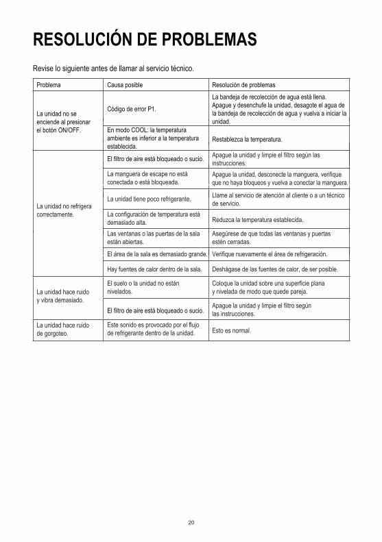
RESOLUCIÓN DE PROBLEMASRevise lo siguiente antes de llamar al servicio técnico.
Problema Causa posible Resolución de problemas
Código de error P1.
Restablezca la temperatura.
La unidad no refrigera correctamente.
Apague la unidad y limpie el filtro según las instrucciones.
La unidad tiene poco refrigerante. Llame al servicio de atención al cliente o a un técnico de servicio.
La configuración de temperatura está demasiado alta. Reduzca la temperatura establecida.
Las ventanas o las puertas de la sala están abiertas.
Asegúrese de que todas las ventanas y puertas estén cerradas.
El área de la sala es demasiado grande. Verifique nuevamente el área de refrigeración.
Hay fuentes de calor dentro de la sala. Deshágase de las fuentes de calor, de ser posible.
El suelo o la unidad no están nivelados.
Coloque la unidad sobre una superficie plana y nivelada de modo que quede pareja.
Apague la unidad y limpie el filtro según las instrucciones.
Este sonido es provocado por el flujo de refrigerante dentro de la unidad. Esto es normal.
La unidad no se enciende al presionar el botón ON/OFF.
La unidad hace ruido y vibra demasiado.
La unidad hace ruido de gorgoteo.
En modo COOL: la temperatura ambiente es inferior a la temperatura establecida.
El filtro de aire está bloqueado o sucio.
La manguera de escape no está conectada o está bloqueada.
El filtro de aire está bloqueado o sucio.
Apague la unidad, desconecte la manguera, verifique que no haya bloqueos y vuelva a conectar la manguera.
La bandeja de recolección de agua está llena.Apague y desenchufe la unidad, desagote el agua de la bandeja de recolección de agua y vuelva a iniciar la unidad.
21
GARANTÍA LIMITADANorpole, Inc. garantiza que cada AIRE ACONDICIONADO PORTÁTIL nuevo no tendrá defectos de materiales ni de fabricación y acepta reparar un defecto de este tipo, si lo hubiera, o reponer piezas nuevas de la unidad (a elección de la empresa) en caso de que fallen durante el período de garantía. Los gastos por piezas y mano de obra en esta unidad están cubiertos por un período de un año a partir de la fecha de compra. Asimismo, Norpole, Inc. garantiza que el compresor (solo sus piezas) no tendrá defectos de materiales ni de fabricación por un período de cinco años. El usuario de la unidad se hará cargo de todos los gastos de mano de obra y traslado relacionados con el diagnóstico y el reemplazo del compresor una vez concluida la garantía inicial de un año. En caso de que deba reemplazarse la unidad o se requiera un reembolso conforme a los términos de esta garantía, el usuario se hará cargo de todos los gastos de traslado para devolver la unidad a la fábrica antes de recibir una unidad de reemplazo o un reembolso. El reembolso o el reemplazo quedarán a criterio de Norpole, Inc. Para recibir el reembolso o el servicio de garantía debe presentarse una copia fechada de la factura o del comprobante de venta. Esta garantía cubre artefactos en uso dentro de los Estados Unidos continentales, Alaska, Hawái y Puerto Rico. La garantía no cubre lo siguiente:
• Daños ocasionados en el envío o por una instalación inadecuada.• Daños ocasionados por uso indebido o incorrecto.• Pérdidas de contenido ocasionadas por fallas en la unidad.• Componentes internos, entre otros, el filtro.• Reparaciones realizadas por agentes de servicio técnico no autorizados.• Llamadas de servicio técnico que no implican defectos de materiales o de fabricación, por ejemplo, instrucciones sobre
el uso adecuado del producto o por una instalación incorrecta.• Reemplazo o restablecimiento de fusibles o disyuntores domésticos.• Fallas del producto por uso con fines distintos a los previstos.• Costos de desecho de una unidad defectuosa que no se devolvió a la fábrica.• Costos de entrega o instalación producto de una unidad que no funciona según lo especificado.• Gastos de viaje y transporte para el servicio técnico del producto si el artefacto se encuentra en un área remota donde
no hay técnicos autorizados disponibles.• La extracción y reinstalación del artefacto, si no se encuentra en una ubicación accesible o no está instalado conforme
a las instrucciones de instalación publicadas.• Los reembolsos por productos no reparables se limitan al precio pagado por la unidad según el comprobante de venta.• Esta garantía no es transferible. La garantía corresponde solo al comprador original y no es extensible a otros futuros
propietarios.
LIMITACIONES DE COMPENSACIONES Y EXCLUSIONESLa reparación del producto de acuerdo con los términos aquí presentados es su único recurso exclusivo cubierto por esta garantía limitada. Todas las garantías implícitas, incluidas las de comercialización y adecuación para un fin en particular, están limitadas a un año o al período más corto permitido por ley. Norpole, Inc. no será responsable por daños incidentales o consecuentes, y ninguna persona ni representante están autorizados a asumir ninguna responsabilidad en nuestro nombre en relación con la venta de este producto. En ninguna circunstancia el usuario tiene permitido devolver la unidad a la fábrica sin el previo consentimiento por escrito de Norpole, Inc.Algunos estados prohíben la exclusión o limitación de daños incidentales o consecuentes, o limitaciones en las garantías implícitas. Esta garantía le concede derechos jurídicos específicos, aunque podría tener otros derechos, que varían de estado en estado.
Modelo Piezas y mano de obra Compresor (solo las piezas) Tipo de servicioNPPAC12HKM Un año Cinco años Reparación en el taller
Para obtener asistencia o información de servicio técnico, llame al 888-775-0202 o visítenos en la Web: www.mcappliance.com.