Embed Size (px)
Citation preview

PORTA-MILKERI N S T R U C T I O N M A N U A L
The Company,Inc. 1-800-776-7042Toll-Free
P.O. Box 147 Whitewater, Wisconsin 53190
www.coburn.com
Phone: 262-473-2822Fax: 262-473-3522
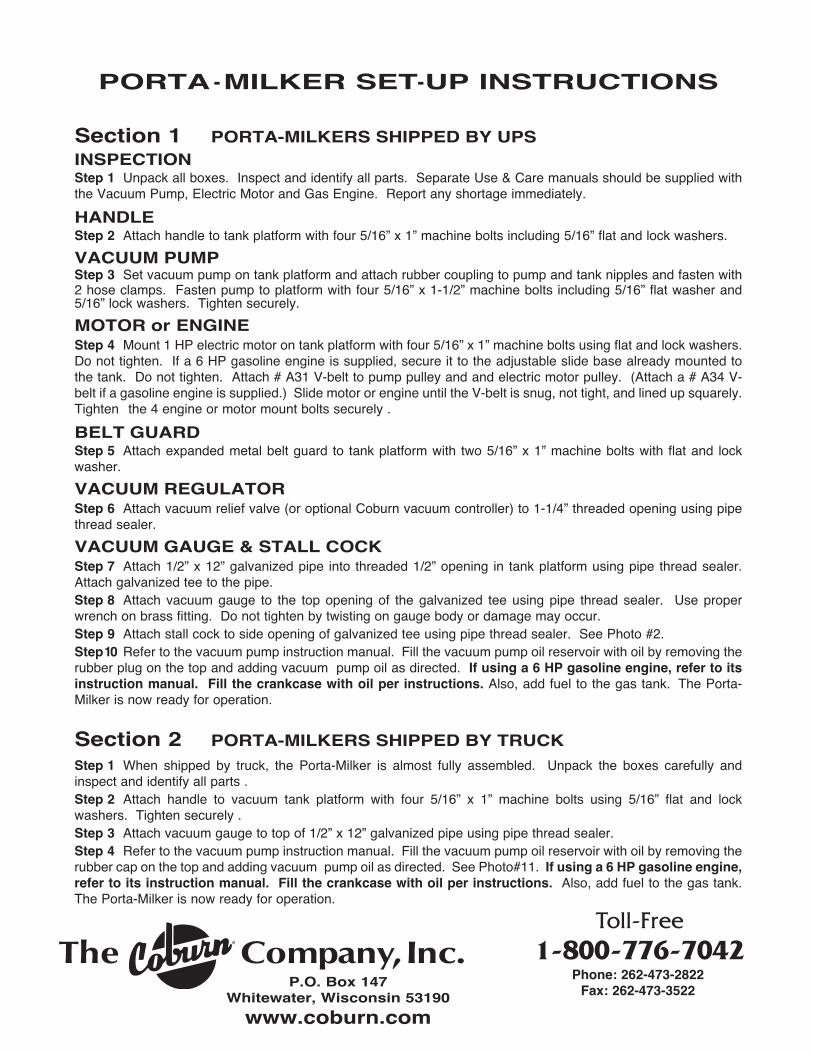
PORTA-MILKER SET-UP INSTRUCTIONS
Section 1 PORTA-MILKERS SHIPPED BY UPSINSPECTIONStep 1 Unpack all boxes. Inspect and identify all parts. Separate Use & Care manuals should be supplied withthe Vacuum Pump, Electric Motor and Gas Engine. Report any shortage immediately.
HANDLEStep 2 Attach handle to tank platform with four 5/16” x 1” machine bolts including 5/16” flat and lock washers.
VACUUM PUMPStep 3 Set vacuum pump on tank platform and attach rubber coupling to pump and tank nipples and fasten with2 hose clamps. Fasten pump to platform with four 5/16” x 1-1/2” machine bolts including 5/16” flat washer and5/16” lock washers. Tighten securely.
MOTOR or ENGINEStep 4 Mount 1 HP electric motor on tank platform with four 5/16” x 1” machine bolts using flat and lock washers.Do not tighten. If a 6 HP gasoline engine is supplied, secure it to the adjustable slide base already mounted tothe tank. Do not tighten. Attach # A31 V-belt to pump pulley and and electric motor pulley. (Attach a # A34 V-belt if a gasoline engine is supplied.) Slide motor or engine until the V-belt is snug, not tight, and lined up squarely.Tighten the 4 engine or motor mount bolts securely .
BELT GUARDStep 5 Attach expanded metal belt guard to tank platform with two 5/16” x 1” machine bolts with flat and lockwasher.
VACUUM REGULATORStep 6 Attach vacuum relief valve (or optional Coburn vacuum controller) to 1-1/4” threaded opening using pipethread sealer.
VACUUM GAUGE & STALL COCKStep 7 Attach 1/2” x 12” galvanized pipe into threaded 1/2” opening in tank platform using pipe thread sealer.Attach galvanized tee to the pipe.Step 8 Attach vacuum gauge to the top opening of the galvanized tee using pipe thread sealer. Use properwrench on brass fitting. Do not tighten by twisting on gauge body or damage may occur.Step 9 Attach stall cock to side opening of galvanized tee using pipe thread sealer. See Photo #2.Step10 Refer to the vacuum pump instruction manual. Fill the vacuum pump oil reservoir with oil by removing therubber plug on the top and adding vacuum pump oil as directed. If using a 6 HP gasoline engine, refer to itsinstruction manual. Fill the crankcase with oil per instructions. Also, add fuel to the gas tank. The Porta-Milker is now ready for operation.
Section 2 PORTA-MILKERS SHIPPED BY TRUCKStep 1 When shipped by truck, the Porta-Milker is almost fully assembled. Unpack the boxes carefully andinspect and identify all parts .Step 2 Attach handle to vacuum tank platform with four 5/16” x 1” machine bolts using 5/16” flat and lockwashers. Tighten securely .Step 3 Attach vacuum gauge to top of 1/2” x 12” galvanized pipe using pipe thread sealer. Step 4 Refer to the vacuum pump instruction manual. Fill the vacuum pump oil reservoir with oil by removing therubber cap on the top and adding vacuum pump oil as directed. See Photo#11. If using a 6 HP gasoline engine,refer to its instruction manual. Fill the crankcase with oil per instructions. Also, add fuel to the gas tank.The Porta-Milker is now ready for operation.
P H O T O G U I D E
PORTA-MILKERI N S T R U C T I O N M A N U A L

The Company,Inc. 1-800-776-7042Toll-Free
P.O. Box 147 Whitewater, Wisconsin 53190
www.coburn.comPhone: 262-473-2822Fax: 262-473-3522
®

P
Q
R
PARTS LIST
Ref. PART NO. DESCRIPTIONA 1900106T TankB 097-2002 Tank handleC OL03CC91 Vacuum pumpD MF0392 Muffler for vacuum pumpE 110088 1 HP electric motor
121432-0036-E2 6 HP gasoline engine (optional)F 1900106BG Belt guard for electric motor
1900106BGTL Belt guard for gasoline engine (optional)G 3400018 Relief valveH 52AC Vacuum Gauge (for units with motor)H 55AC Vacuum Gauge (for units with engine)I 12S Stall cockJ A31 V-Belt (for motor)J A34 V-Belt (for engine)K 5/16” x 1” Machine bolts, flat & lock washersL 5/16” x 1-1/2” Machine bolts, flat & lock washersM 161 BumperN 9120100 Plastic drain valveO 110-58-OFHD 10 X 1.75 WheelP 5/16” x 1” Machine bolts, flat & lock washers (motor)Q 3X911-5 Pump PulleyR 3X907-3 Pulley (for motor)R 3X897 Pulley (for engine)
Gasoline engine ismounted on adjustableslide base - not shown.

Operating Instructions
Milking with your Coburn Porta-Milker
1. Set up your Porta-Milker according to the instructions in this manual. Plug electric motor into heavy duty 3-prong grounded power cord. For gasoline engines, pull starter cord only after checking oil and gas level. Oncemotor or engine is running, wait a few moments, then visually inspect clear tube on vacuum pump oiler to makesure that oil is flowing to the pump.
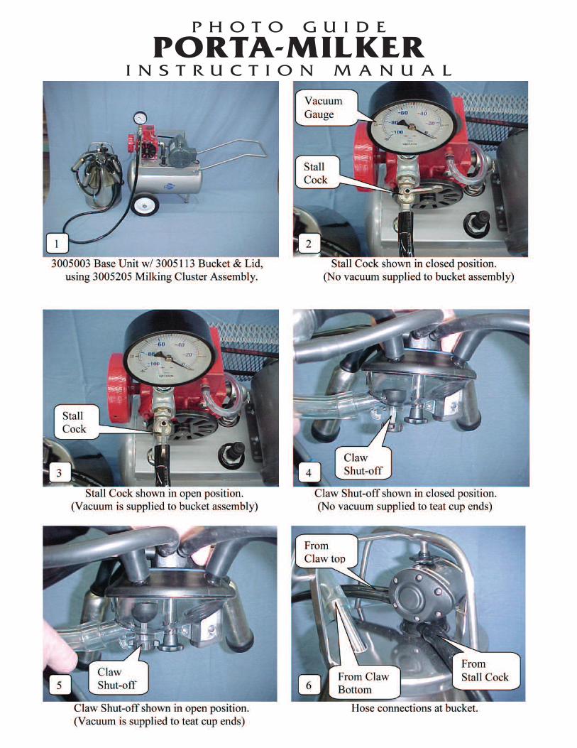
With the stall cock (item I on the parts list) in the closed position (see Photo #2), the vacuum gauge (H) shouldread 15” if milking cows, or 13” for goats or sheep. If not, the vacuum relief valve (G) can be adjusted by looseningthe locking nut and turning the body until the desired vacuum level is reached. See photo #12. If you are usingthe optional 173-02010 Coburn Vacuum Regulator, turn the top adjustment screw until the desired vacuum levelis reached.
Attach tubing from stall cock (I) to black adapter nipple on the bucket lid as in photos #6 and #10. Assembleyour claw cluster per photos #7 and #8. Attach the appropriate hoses to the bucket lid and pulsator per photo #6.Slide the locking bucket handle into place above the pulsator to tightly join the lid and bucket. If the handle is verystiff, you may adjust the knurled nut (photo #9) to loosen slightly. Readjust the knurled nut in future to keep a firmseal. You are now ready to begin milking.
2. THE MILKING PROCEDURE Before attaching the teat cups, the animal should be prepared by carefulwashing and drying of the teats. Hand strip the initial milk. This helps stimulate the udder to let down the milk andalso helps remove bacteria and impurities from the teat end.
Holding the claw in one hand, make sure the teat cups and shells droop (bend) over the stubs of the claw asin photo#7. Open the shut-off on the bottom of the claw and lock open. While kneeling next to the animal, lifteach individual teat cup and attach. Try to do this in a rapid efficient manner so as not to lose milking vacuum.
When the animal is finished milking, close the shut-off at bottom of claw (photo #4) so as not to pull the teatcups off the udder under vacuum.
To empty the bucket, shut off stall cock at vacuum source per photo #2. Then open the shut-off, photo #5,to release vacuum in bucket. Do not overfill the bucket when milking as this could flood the vacuum tank. If thishappens, the vacuum tank must be thoroughly flushed.
3. THE WASHING PROCEDURE After milking, the cluster and buckets must be washed immediately. Hold claw upside down so teat cups and shells hang down. Open claw shut-off, photo #5. Plunge the teat
cups in and out of the rinse water to draw water and air through the claw and into the bucket. Use about 10 liters.Shut off vacuum and drain the bucket. Repeat above procedure this time adding a suitable soap (detergent) tothe 10 liters of water. Shut off vacuum and drain. Repeat plunging procedure, this time with 10 liters of cold waterwith a sanitizing (disinfectant) added.
Wash and rinse bucket gasket and outside surfaces of bucket and cluster. Hang cluster to dry. Turn bucketupside down to drain, then wipe dry to be sure no no trace of detergent, disinfectant or hard water is left on thesurface of the stainless steel. Over time, this could cause pitting or corrosion. Careful attention to the cleaningand drying procedure is essential to preserve both your milking equipment and your animal’s health.
4. PERIODIC MAINTENANCE Every day: Check oil level on pump reservoir per photo #11. Check vacuum level. Check drain valve (part
N) at bottom on tank. It should close under vacuum and open off vacuum to drain tank moisture.Every 6 months. Flush vacuum pump. Change teat cups (inflations) every 6 months or 1200 milkings.Every year: Change all rubber parts, gaskets and hoses. If you are storing your pump for more than 1 month:
Flush pump with flushing oil or kerosene. Put fresh oil in pump. Run pump for a few minutes at least once perweek.
PMIM2012
The Company,Inc. 1-800-776-7042Toll-Free
P.O. Box 147 Whitewater, Wisconsin 53190
www.coburn.com
Phone: 262-473-2822Fax: 262-473-3522

The Company,Inc. 1-800-776-7042Toll-Free
P.O. Box 147 Whitewater, Wisconsin 53190
www.coburn.com
Phone: 262-473-2822Fax: 262-473-3522
INSTRUCCIONES DE ENSAMBLAJE DE SU PORTA MILKERSECCION 1 PORTA MILKER ENVIADO POR UPS o COURRIERINSPECCION: Abra todas las cajas e identifique todas las partes. Reporte inmediatamente cualquier faltante.JALADOR O MANIJA: Incorpore el jalador de su Porta Milker a la plataforma del tanque de vacio. Atornille el jalador con cuatro tornillos 5/16” x 1”y washas de 5/16” BOMBA DE VACIO: Coloque la bomba de vacío en la plataforma del tanque de vacío y ajústela con dos coplas de hule en las roscas del tanque.Luego ajuste la bomba con cuatro tuercas 5/16” x 1 1/2” incluyendo sus washas de 5/16”. Apriete las tuercas con firmeza.MOTOR: Coloque el motor eléctrico de 1HP en la plataforma del tanque con cuatro tuercas de 5/16” x 1” usando las washas delmismo diámetro. Si su equipo incluye el motor Gasolina de 6 HP colóquelo en la base ajustable montada ya en el tanque devacío. No lo apriete. Coloque un faja #A31 a el pulley de la bomba de vacío y al pulley de el motor eléctrico. ( coloque unafaja #A34 si su motor es de gasolina). Deslice la bomba o el motor en la base ajustable hasta que la faja esta tensa pero noajustada. Alinear y ajustar bien el motor con 4 tuercas de motor.PERSIANA PROTECTORA: Ajuste la persiana protectora de metal a la plataforma del tanque de vacío con dos tuercas 5/16” x 1” con sus respectivaswashas.REGULADOR DE VACIO:Ajuste la válvula de alivio o su regulador de vacío Coburn a la salida de 1 1/4” del tanque de vacío y séllelo adecuadamenteusando un sellador de para tuberías metálicas. MEDIDOR DE VACIO:Insertar un tubo galvanizado de 1/2” x 12” a la salida de 1/2” en la plataforma del tanque usando sellador de metales paratuberías. Coloque el medidor de vacío 55AC a la parte superior de el tubo galvanizado de 1/2” x 12 usando el sellador.Utilice la llave inglesa que mejor se ajuste a la tuerca de cobre del medidor de vacío y apriétela delicadamente o puedenocurrir danos. GRIFOS:Coloque los grifos 12S a las aberturas de la tubería galvanizada y ajústelas usando el sellador para tuberías metálicas.ACEITES Y COMBUSTIBLES:Agregue aceite en el recipiente indicado removiendo el tapón de plástico, asegurase de utilizar aceite especifico paramotores de vacío (aceite hidráulico sin aditivos) como lo indica su manual de instrucciones. Para unidades con motor degasolina lea el manual de instrucciones del motor y agregue los combustibles según se indica. Por favor lea todos losmanuales adjuntos con esta maquinaria antes de utilizarla. Su PORTA MILKER esta lista para ser operada.
SECCION 2 PORTA MILKER EMBARCADA POR CAMION:PASO #1: Cuando su equipo de ordeno PORTA MILKER ha sido enviado por camión, el equipo esta casi ensamblado en sutotalidad. Abra las cajas e inspeccione detenidamente el contenido de la caja, identifique las piezas y asegurase que elcontenido este completo. JALADOR O MANIJA: Incorpore el jalador de su Porta Milker a la plataforma del tanque de vacío. Atornille el jalador con cuatro tornillos 5/16” x 1”y washas de 5/16” REGULADOR DE VACIO:Ajuste la válvula de alivio o su regulador de vacío Coburn a la salida de 1 1/4” del tanque de vacío y séllelo adecuadamenteusando un sellador de metales para tuberías. MEDIDOR DE VACIO:Insertar un tubo galvanizado de 1/2” x 12” a la salida de 1/2” en la plataforma del tanque usando sellador de metales paratuberías. Coloque el medidor de vacío 55AC a la parte superior del tubo galvanizado de 1/2” x 12 usando el sellador.Utilice la llave inglesa que mejor se ajuste a la tuerca de cobre del medidor de vacío y apriétela delicadamente o puedenocurrir danos. ACEITES Y COMBUSTIBLES:Agregue aceite en el recipiente indicado removiendo el tapón de plástico, asegurase de utilizar aceite especifico paramotores de vacío (aceite hidráulico sin aditivos) como lo indica su manual de instrucciones de uso. Para unidades conmotor de gasolina lea el manual de instrucciones del motor y agregue los combustibles según se indica. Por favor lea todoslos manuales adjuntos con esta maquinaria antes de utilizarla. Su PORTA MILKER esta lista para ser operada.
®
Ordeñando con su Coburn Porta-Milker1. Establezca su Porta-Milker.Conecte el motor eléctrico en conector de 3 entradas y coloque la unidad en la superficie del piso apropiada-mente. Para motores de gasolina asegurese que el nivel de aceite y combustible estén correctos antes deestirar el cordón de encendido.Una vez que el motor o maquina corran, inspeccione visualmente el tubo transparente cerciorándose que elaceite fluya a la bomba. Con la válvula de vacío (articulo I en las lista de partes) en posición cerrada, el calibrador de vacío (H) debeleer 15” si ordeña vacas, o 13 para cabras u ovejas. Si no, la válvula de alivio de vacío (G) puede ser ajustadaaflojando la tuerca y girando el cuerpo de la válvula hasta que se alcance el nivel de vacío deseado. Conecte latubería de la unidad de ordeño (I) al pezón plástico negro en la tapa del balde.Usted está ahora listo para conectar sus unidad de ordeño a el balde y comenzar a ordeñar.
Atención : Si utiliza el regulador de vacío 173-02010 Coburn (opcional) dé vuelta al tornillo de ajuste superiorhasta que se alcance el nivel deseado del vacío2. Procedimiento de ordeño.Antes de conectar las pezoneras, debe de establecer una rutina higiénica de lavado de pezones con algúnlíquido desinfectante para prevenir problemas de mastitis. Ordene a mano una muestra inicial de la leche a untazón de fondo oscuro y revise la consistencia de la leche, esta rutina ayudara a estimular la ubre y bajar laleche, también ayuda a remover bacteria e impurezas en la punta de los pezones. Sostenga la unidad deordeño en una mano y asegurese que las pezoneras caigan sobre el balde recolector de leche.Abra la válvula en la parte de abajo de la unidad de ordeño y arrodillece cerca del animal, levante cada copa yconéctela al pezón. Trate de hacerlo de manera rápida y eficiente para no perder el vacío.Cuando el flujo de leche deje de circular, cierre la abrazadera repentina o válvula de vacío del recolector paracortar el flujo de vacío. Procure no desprender las pezoneras de la ubre cuando todavía haya presencia devacío en las pezoneras esto evitara lesiones en los pezones.Para vaciar el balde de leche cierre la válvula de vacío en la tubería, luego abra el soporte o válvula de launidad de ordeño para liberar el vacío en al balde de leche, esto hará que toda la leche en la manguera caigadirectamente al balde.
3. Procedimiento de lavado.Después de ordeñar, el equipo y balde deben ser lavados inmediatamente. Detenga la unidad de ordeñobocabajo para que las pezoneras cuelguen. Abra la abrazadera repentina o la válvula de unidad de ordeño.Sumerja y saque las pezoneras paulatinamente de 10 a 15 veces en un balde de agua (con aproximadamente10 litros) para que el aire y agua corra por la unidad de ordeño hacia el balde. Cierre el vacio y desagüe elbalde.Repita el procedimiento de arriba, esta vez agregue detergente adecuado para 10 litros de agua. Luego repita,esta vez use 10 litros de agua fria con un desinfectante adherido. Lave y enjuague los empaques y lassuperficies exteriores del balde y equipo. Cuelgue el equipo a secar. Voltee el balde bocabajo para desaguar,luego secar y asegurese que no queden residuos de detergente, desinfectante o agua dura en la superficie delacero; con el tiempo, esto podría causar corrosión. La atención cuidadosa al limpiar y secar es esencial parapreservar tanto su equipo de ordeña como la salud de su animal.
4. Mantenimiento Periodico.Asegurese de chequear el nivel de aceite del motor de su ordenadora todos los días. Verifique el nivel delvacío, el ritmo de pulsación, y la válvula de desagüe en el tanque.Cada 6 meses: Limpie completamente la bomba de vacío. Cambie los pezoneras cada 6 meses o 1200 ordeñadas.Cada año: Cambie todos los plásticos, empaques y mangueras. Si usted almacena su bomba por mas de unmes: limpie la bomba con aceite limpiador. Ponga aceite nuevo y arranque la bomba por algunos minutoscuando menos una vez a la semana.
PMSP2012
The Company,Inc. 1-800-776-7042Toll-Free
P.O. Box 147 Whitewater, Wisconsin 53190
www.coburn.com
Phone: 262-473-2822Fax: 262-473-3522
®


![cosmari [Sola lettura] [modalit compatibilit ]) · rsu porta a porta system mechanical biological treatment recovery bio gas landfill recovery multi-material paper porta a porta system](https://img.pdfslide.us/doc/110x75/5e3da4aaace15f78c848e948/cosmari-sola-lettura-modalit-compatibilit-rsu-porta-a-porta-system-mechanical.jpg)