Embed Size (px)
Citation preview

Porous Media Filtration
Definition: Removal of colloidal (usually
destabilized) and suspended material from water
by passage through layers of porous media.
Water treatment: turbidity removal
Wastewater treatment: tertiary filtration (removal
of very fine suspended particles)
TYPES OF FILTERS
The filters described below are modern types used
for water/wastewater treatment purposes.
Variations of these filter types and other types are
discussed at the end of this section. In all filters
the primary design/operating parameters are:
• quality (SS concentration) of the effluent.
•headloss through the filter and appurtenances.

Deep Granular Filters
Deep granular filters are made of granular
material (sand, anthracite, garnet) arranged in a
bed to provide a porous media as shown in the
figure below. Filter bed is supported by gravel bed
as also shown below. Flow is typically in the
downflow mode. Upflow mode is used but much
less frequently.

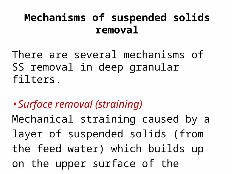
Mechanisms of suspended solids removal
There are several mechanisms of SS removal in deep granular filters.
•Surface removal (straining)
Mechanical straining caused by a layer of
suspended solids (from the feed water) which
builds up on the upper surface of the porous
media. This type of removal is to be avoided
because of the excessive head loss that results
from the suspended solids layer's compressibility.

Filter media
Suspended solids
Flow
Top of filtermedia

•Depth removalDepth removal refers to SS removal below the surface of the filter bed. There are two types of “depth removal”.
Interstitial strainingLarger particles become trapped in the void space between granular media particles.

Suspended solid
Filter media
Flow

AttachmentSuspended solids are typically flocculent by design (filter often follows coagulation/flocculation) or by nature (clays, algae, bacteria). Therefore, attachment or adsorption of suspended solids is a good possibility. Attachment can be electrostatic, chemical bridging or specific adsorption. Attachment is enhanced by addition of small amount of coagulant and as the filter bed becomes coated with suspended solids ("ripened" filter). It is easier for suspended solids to attach to other SS that are already attached to the filter media.

Suspended solid
Filter media
Flow

In general all three mechanisms of removal are occurring at the same time during a filter run. The relative predominance of these mechanisms depends on:•character of media•character of SS•temperature•flow rate•bed depth•time (throughput volume)

Filter Cycle
As filter run proceeds deposits build up in the upper
portion of the filter bed. As a consequence void
volume decreases, interstitial flow velocity increases
with more hydraulic shear on the trapped and
attached SS. This drives some of the filtered SS
deeper into the filter bed. Ultimately the SS get
washed into the effluent.

At this point the filter must be backwashed to clean
the filter bed surfaces. The filter is then put in the
forward flow mode again. It is possible (and
likely) that the head loss through the bed becomes
high enough that the bed has to be backwashed
before the effluent quality becomes unacceptable.
Head loss builds because the void space shrinks
with time. Head loss is usually what determines
time to backwashing. Therefore, it is important to
know the hydraulics of granular filters.

Hydraulics of Deep Granular Filters
Hydraulics of flow through porous media can be described by D'Arcy's law if flow is laminar.
L
hKSKV f
plp

V = superficial approach velocity (ft/min).
Kp = coefficient of permeability (ft/min). This
will change with time in the filter.
Sl = hydraulic gradient (hf/L) dimensionless
hf = frictional head loss (ft)
L = depth of filter (ft).

Alternatively, the empirical Carmen- Kozeny ,
Fair-Hatch, Rose or other equations are more
appropriate because the pore volume will
continually change as suspended solids are
removed.
For example the Carmen-Kozeny equation is
often used:

2
p
s3
2f
dV
)1(
gJ
L
h
= kinematic viscosity (ft2/sec)
J = packing factor (empirical) ~ 6 for laminar
flow
= porosity = void volume fraction of filter bed
g = acceleration of gravity (ft/sec2)
dp = measured particle dia (ft).

dp is commonly taken as geometric mean of
adjacent sieve sizes that pass and retain the particles. For non-uniform size media particles divide the bed into incremental layers and use geometric mean size in each layer (d1 x d2)
0.5=
dp for that layer. Compute hf/L for each layer
and sum for total bed. d1 is size passed d2 is size
retained for a particular layer. Sometimes the effective size of the particles is used here.
effective size = size for which 10% of sample (by wt.) is smaller (d10) .

s= shape factor, measure of particle
irregularity
= 6 for spheres
= 8.5 for crushed granular media.

Typical sand filter media:
effective size = 0.5mm
uniformity coefficient. = 1.75
uniformity coefficient. = size for which 60% of
sample (wt) is smaller (d60)/effective size. =
d60/d10.

Headloss Development in Granular filter
The Bernoulli equation (conservation of energy) can be used to model head loss through a granular filter:
constanthZp
g2
Vf
2i

Vi = interstitial flow velocity, ft/sec.
= specific wt of water = 62.4 lbs/ft
Z = depth measured from datum, ft.
For no flow (hydrostatic conditions):
constantZp

Head loss patterns change as the filter run
proceeds; interstitial velocity increases as pore
size decreases (first in the upper portions of filter)
and as the velocity increases the frictional head
loss increases. Since the progression of head loss
increases non- uniformly throughout the filter we
get the following head loss pattern.


In the region of negative pressure degasification of
the water can occur. This may cause air binding
and reduction in the effective filter surface area.
Negative pressure regions can also cause cracking
of the filter (results in fissures in bed that allow
unfiltered water to pass through to effluent).

Pretreatment
If the sand filter is not preceded with a
coagulation/flocculation process (as is typically
the case for water treatment systems),
pretreatment of the suspended solids is often
employed, particularly if the water contains
fine clays. Pretreatment is usually the addition
of coagulant just before the filter. The filter
acts as a flocculation process as described
earlier.

Head loss patterns
When depth removal is the primary mechanism
for SS removal the head loss pattern is shown in
the following figure. Head loss increases with
surface loading rate due to higher solids loading
rate as well as higher frictional head loss.


At lower surface loading rates surface removal is
significant because the velocity is not high enough
to drive the SS into the media (At higher loading
rates the suspended solids are driven into the
media). The compressibility of the surface layer
results in higher headloss at higher velocity.


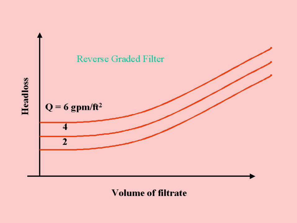
Reverse graded filters are used to enhance depth
removal and reduce surface removal. A more
uniform solids distribution results. Thus longer
filter runs can be attained. Filter runs of 2-5 times
longer than single media filters are attainable.
Head loss patterns for a reverse graded filter are
shown in this figure.

Effluent Quality (turbidity) patterns for various depths in a granular filter are shown here:

Effluent quality at any layer tends to improve
initially, then get worse with time or throughput.
As SS are removed by adsorption and straining the
media surface area increases (giving better
adsorption/attachment) and the void spaces
become smaller (giving better straining). As the
channels become smaller interstitial velocity
increases and we get greater shear which results in
sloughing to lower layers of media.

DESIGN OF GRANULAR FILTERS
Modes of Flow ControlPossibilities: •Constant pressure, •constant rate, •declining rate
Only constant rate and declining rate are reasonable from economic, practical point of view. So these are the only two we will discuss.


Constant rate filtration
In this mode of operation a constant flow rate (Q) is
applied to the filter. This constant Q is usually
controlled by a system of weirs. This usually
requires a wet well (storage) if we are treating a
wastewater. As the filter run proceeds and head
loss increases, water level in the filters increases to
compensate for greater head requirement. A
schematic of a constant flow filter is shown here.


Declining rate filtration
In this scheme the filters are operated in parallel
with common influent header. 4 parallel filters
are operated so that one filter is down and being
backwashed and the other filters take up the
slack. When one filter is down the flow increases
to the other 3. The head in each of the other
three increases somewhat to force more flow (to
accommodate the extra flow from the down
filter).

Distributing the flow across all the filters evens
out the cycle and produced a declining rate (but a
gradual declining rate). Net result is that headloss
is the same in all filters but Q is not. In fact the
individual filter rate declines gradually.

Advantages:
•· Better filtrate quality since we don't try to
force high velocity through a clogged filter as
in the constant rate system.
•· Lower headloss in influent since there are
no weir losses involved.


Filter Configuration
Downflow filters are the most conventional. In
the upflow mode the filter needs a grid on surface
to prevent sand from flowing out of the top. One
advantage of upflow filter is that we can take
advantage of the reverse grading of the filter bed
(coarser particles at bottom or influent side). In
the downflow mode sand is usually naturally
graded in the opposite direction relative to flow.

Reverse grade helps to extend filter run. Another
disadvantage of the upflow mode is that
hydraulic perturbations can lift the bed allowing
suspended solids to escape. Usually the depth of
upflow bed is 6 -10 ft. as compared to 1 to 3 ft in
the downflow mode.


Filter mediaImportant considerations in selecting media:
•· too fine - surface straining which results in high head loss and short filter runs.
•· too coarse - poor filtrate quality , high backwash flow required.

Single media:Sand :
•24"-30" depth
•Effective size = 0.4-1.0 mm.
•Uniformity coefficient < 1.65
•Density = 2.65.
•Porosity = 0.43

Dual media:
To compensate for the unfavorable gradation that
occurs in the single media filters we can use dual
media (reverse graded) filters. Place a less dense,
larger diameter media on top of sand. This results in a
higher porosity (0.55) at top of filter. Sand has
porosity of about 0.4. Lower density also allows the
less dense media to remain on top after backwashing.

Media Depth
(in)
Eff Size
(mm)
Uniformity
Coefficient
Anthacite 12 – 20 0.9 – 1.0 < 1.8
Sand 12 – 16 0.5 – 0.55 <1.65

This combination will allow about 6" of
intermixing so that there will not be an
accumulation of suspended solids at a sudden
porosity change interface.
This will also allow fluidization (backwash)
for both layers at approximately the same Q.

Trimedia Filters
Garnet sand (density = 4-4.2 g/cc) is some
times used below the sand in a third layer.
Difficulties arise in keeping the sand and garnet
from intermixing during backwash. In general
this extra layer not worth the extra trouble.

Filtration rate
• 1-8 gpm/ft2 = the acceptable range • 2-3 gpm/ft2 = average flow loading rates
• 4-5 gpm/ft2 = peak flow loading rate

Terminal headloss•Commonly 3 - 5 ft for water treatment
•Up to 10 ft for wastewater treatment (biological floc can tolerate more shear force than chemical floc without breaking up)
•Filter run = T = f( floc strength, Q and suspended solids concentration in influent).


It turns out that the optimum T for filters is
between 12 and 30 hrs at least for water
treatment where the primary objective is
water production. This is explained as
follows.
If T<12 hours all of the filters will not be
used simultaneously enough of the time. This
results in overloading the on-line filters for a
higher percentage of the time.

Filters can be "overloaded" for short periods of time but overloading for extended periods creates the requirement that the filter size should be increased. Where does the 12-hour lower limit come from? The following figure helps explain.


A plot of % time all filters are in use versus T
shows that the % that all filters are in use
asymptotically approaches about 80% @ about T =
12 hrs. This is based on 30 minute downtime for
backwashing and 4 filters operated in parallel.
Note that T cannot be less than 1.5 hours for 4
filters if only 1 filter is to be backwashed at a time.
So anytime that backwashing is going on the on-
line filters are carrying 1.33 of the design flow. In
the case of T = 12 hrs, this overload is only going
on for 20% of the time (an acceptable scenario).
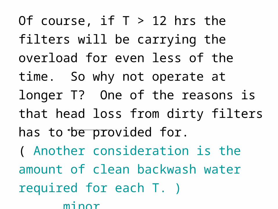
Of course, if T > 12 hrs the filters will be
carrying the overload for even less of the time.
So why not operate at longer T? One of the
reasons is that head loss from dirty filters has to
be provided for. ( Another consideration is the
amount of clean backwash water required for
each T. ) minor
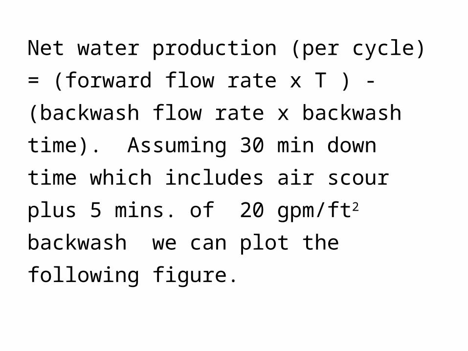
Net water production (per cycle) = (forward
flow rate x T ) - (backwash flow rate x
backwash time). Assuming 30 min down time
which includes air scour plus 5 mins. of 20
gpm/ft2 backwash we can plot the following
figure.


In this figure @ T = infinity applied filtrate =
produced filtrate. For T > 30 hours there is
very little advantage in terms of net production
of water. So there is no reason to go beyond
this T and, in fact, we only encounter more
headloss for little gain in productivity . So we
may as well stop at this point.

Backwash requirements
When terminal head loss is reached the filters must
be backwashed with clear water. Usually this clear
water comes from the wet well that follows the
filter. For downflow filters backwashing is done by
fluidizing the bed in an upflow mode. Wash water
is collected at the top of the filters in wash gutters
and either sent back to the head end of the plant or
to the sludge treatment train.

Backwash sequences
Bed expansion is between 15-30% accomplished
by applying a backflow rate of about 15 gpm/ft2
for 5 - 10 mins. Hydrodynamic shear cleans the
media particles (attached, as well as strained).
Optimum shearing occurs at about 50 %
expansion but this tends to require excessive
backwash velocities with coarser media particles
and these high flow backwashs could fluidize the
gravel underdrain.

Surface wash: Surface wash water is sometimes pumped at high velocity 1-2" above unexpanded bed. Surface wash can be used prior to and/or during expansion.
Air scour: air introduced just above gravel underdrain , 3-5 min prior to backwashing. (3- 5 scf/ft2 of air).

Hydraulics of backwash bed expansion
We need to know velocity and flow rate necessary
to fluidize bed so that pumps and wet wells can be
designed appropriately.
Mathematical description of bed expansion:
)1(
)1(
D
De

)1(D
D1
e
, are, respectively, the unexpanded and expanded porosity of a clean bed.
D, De are the unexpanded and expanded depth of
the media.

An empirical observation relates the required approach velocity to the extent of fluidization:
ene )(KV
Where V is the approach velocity required to attain a certain level of bed expansion.ne and Ke are constants that can be evaluated by a
settling analysis of the media.

The following is an empirical expression that relates minimum fluidization velocity to media particle settling velocity.
fs V45.8V
(units don’t matter as long as they are consistent)
Vs = settling velocity of the media
Vf = minimum fluidization velocity of the
media.

Another empirical observation:
0.1e 0n 4.45Re (dimensionless)
60sl0
dVRe
60fl0
dV45.8Re
or:

f0 Re45.8Re
0.1e f
0.1f
n 4.45(8.45 Re )
3.59 Re

Vf can alternatively be computed using
another empirical relationship:
88.0
94.0sms
82.160
f
)}({)d(00381.0V
(be careful to use the proper units since this is an empirical relationship)

s,m = specific weight of water, media (lb/ft3)
= viscosity of water (centipoise)
d60 has units of millimeter.
Vf = min. fluidization velocity in gpm/ft2

272.0fR Re775.1K
If Ref > 10 then we need to apply a correction
factor:
fR'f VKV
' 0.1e fThen use: n 3.59(Re )

Use initial porosity and the empirical equation for fluidization velocity to compute Ke.
enf
eV
K
Now the fluidization velocity for any bed expansion can be calculated using :
ene )(KV

Pressure drop through the expanded bed is equal to
the buoyant wt. of the bed (no expansion
dependency):
2
m s
media H O
D(1 )( )p
62.4D(1 )(sp.gr. sp.gr. )

For multimedia beds apply expansion and
pressure drop equations separately to each media
layer.

Underdrain and washwater gutter design
Washwater gutter design
Washwater gutters carry away the backwash
water that is laden with suspended solids. These
gutters are located so that horizontal travel of
suspended solids is less than 3 feet. This will
assure capture of most of the released solids.
This translates to maximum horizontal spacing
of about 6' between gutters.

Gutters are located about 12" above top of
expanded bed. This minimizes the amount of
dirty water left in filter box and it also
minimizes possible media loss.


Sizing rectangular gutters
Flow capacity of rectangular gutter
W = width of gutter (ft)Du = depth of water in channel (ft)
Q in cfs
Actual design depth D = Du + 2-3" freeboard.
5.1u )D(W5.2Q
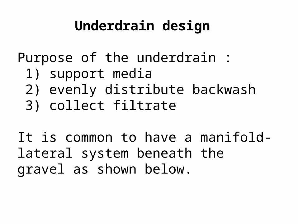
Underdrain design
Purpose of the underdrain : 1) support media 2) evenly distribute backwash 3) collect filtrate
It is common to have a manifold-lateral system beneath the gravel as shown below.

Laterals are perforated on the bottom with holes
located 3 - 12" apart. Hole size = 1/4 - 1/2". To
get even distribution of flow orifice head loss
made purposely high relative to head loss
through the laterals. Common orifice head loss is
about 15 ft.

Total head required for backwash is then sum of:
1) orifices
2) expanded bed
3) flow through gravel
4) manifold and lateral (minor)
5) elevation difference between backwash supply
and wash gutters.
Backwash water is provided by an elevated tank
or pump.

SLOW SAND FILTERS
Slow sand filters (as opposed to "rapid sand
filters", the type discussed above) are operated
at a much lower loading rate. Surface filtration
is promoted in these filters because of the lower
loading rates and because the effective size of
the sand is smaller than that of the rapid sand
filters. Effective size for these filters is 0.35 mm
(uniformity coeff. = 1.75) as compared to 0.4 -
1.0 mm for rapid sand filters.

•Head applied above sand: 3-5 ft.
•Depth of sand is also about 3- 5 ft.
•Loading rates: 0.05 - 0.1 gpm/ft2
•T: 1-6 months

No backwashing is employed with these filters,
instead the upper 1 - 2" of sand is periodically
scraped off and removed with periodic addition of
new sand .
Removal mechanism primarily by filter cake on
the surface of the sand. This layer is called a
"schmutzedecke". The schmutzedecke is
composed of inorganic and biological material
therefore removal is by straining, adsorption and
bioxidation.

Advantage: No backwash requirements, good
removal.
Disadvantage: Need large surface area because of the
low hydraulic loading rate.

Precoat Filters
Description:
The filtration media is hydraulically deposited on
a septum. The filtration media is usually perlite
(siliceous volcanic rock), activated carbon or
diatomaceous earth (siliceous exoskeletons of
algae and diatoms).


Mechanism of SS Removal
Removal is primarily by mechanical straining
by the cake of suspended solids that builds up
on the precoat. In other words “surface”
filtration is the major type of activity.

Pretreatment
Pretreatment for precoat filtration usually involves
adding a “body feed” to the feed stream. Body feed
is simply material of the same composition as precoat
material itself. The objective of the body feed is to
minimize compressibility of the surface cake and to
fill in any accidental holes where the precoat has not
covered the septum. It is presumed that the body feed
is incompressible. Body feed/conc. of SS (influent) =
3-6.
Headloss patterns
Head loss versus Q depends on whether body
feed has been added. W/O body feed head-loss
varies very non-linearly with Q since
compressibility is a big factor. Body feed
addition helps reduce this unfavorable non-
linearity.

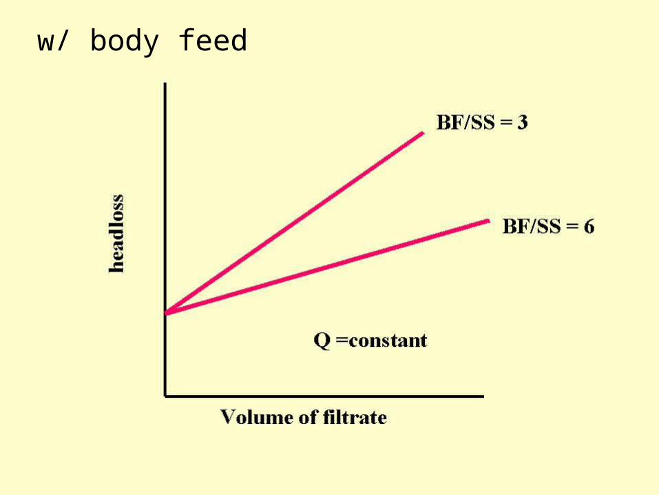
w/ body feed

DESIGN OF PRECOAT FILTERS
Filter cycle:
• application of precoat: 0.1 - 0.2 lbs/ft2 ( 1/16-
1/8" thickness). This is applied at a rate of about
1 gpm/ft2. Application requires about 3-5
minutes. Initial head loss is about 0.5 to 1.5 ft.
This high head loss gives some idea how tight
the precoat porosity is.

• Filtration of water plus body feed:
Q = 0.5- 2.5 gpm/ft
T = 24 hrs.
Optimum body feed dosage equals that which
gives linear headloss vs. filtrate volume
Optimum terminal headloss = 75-150 ft.