Embed Size (px)
Citation preview

Population Balance Models for Granulation Process Design
Jim LitsterSchool of Chemical Engineering
Department of Industrial and Physical PharmacyDepartment of Industrial and Physical PharmacyPurdue University
AcknowledgmentsAcknowledgments• Collaborators: • Current and formerCollaborators:
– Sotiris Pratsinis
– Brian Ennis
Current and former students– Anthony Adetayo
– Charles Emmanuel
– Frank Doyle
– Lian Liu
– Simon Iveson
– Ian Cameron
– Fu Yang Wang
C l W
– Karen Hapgood
– Hans Wildeboer
B F i i h– Carl Wassgren – Ben Freireich
– Jonathan Poon
– Rohit RamchandranRohit Ramchandran
OutlineOutline
• Introduction to granulation processes
• Modelling coalescence– A little bit of history
– Multidimensional PBM
• Modelling nucleation and layering
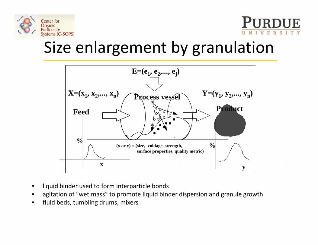
Size enlargement by granulationSize enlargement by granulationE=(e1, e2,..., ej)
X=(x1, x2,..., xn) Y=(y1, y2,..., yn)Process vesselP d t
j
Feed Product
%
x
%
y
(x or y) = (size, voidage, strength, surface properties, quality metric)
• liquid binder used to form interparticle bonds• agitation of “wet mass” to promote liquid binder dispersion and granule growth
y
• fluid beds, tumbling drums, mixers
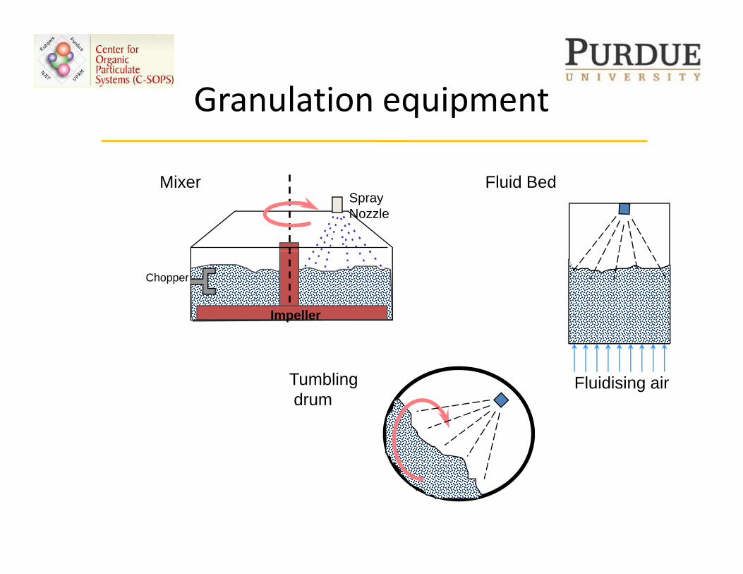
Granulation equipmentGranulation equipment
Fl id B dMi Fluid BedSprayNozzle
Mixer
Impeller
Chopper
Tumblingd
Fluidising airdrum
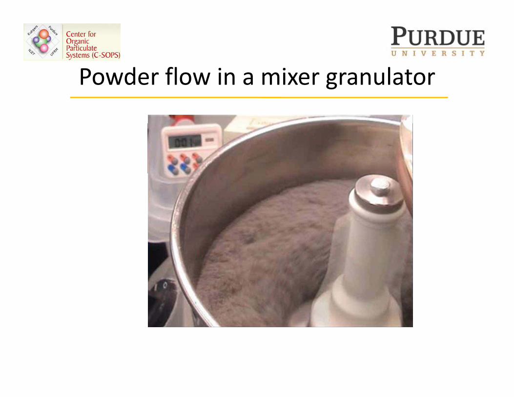
Powder flow in a mixer granulatorPowder flow in a mixer granulator
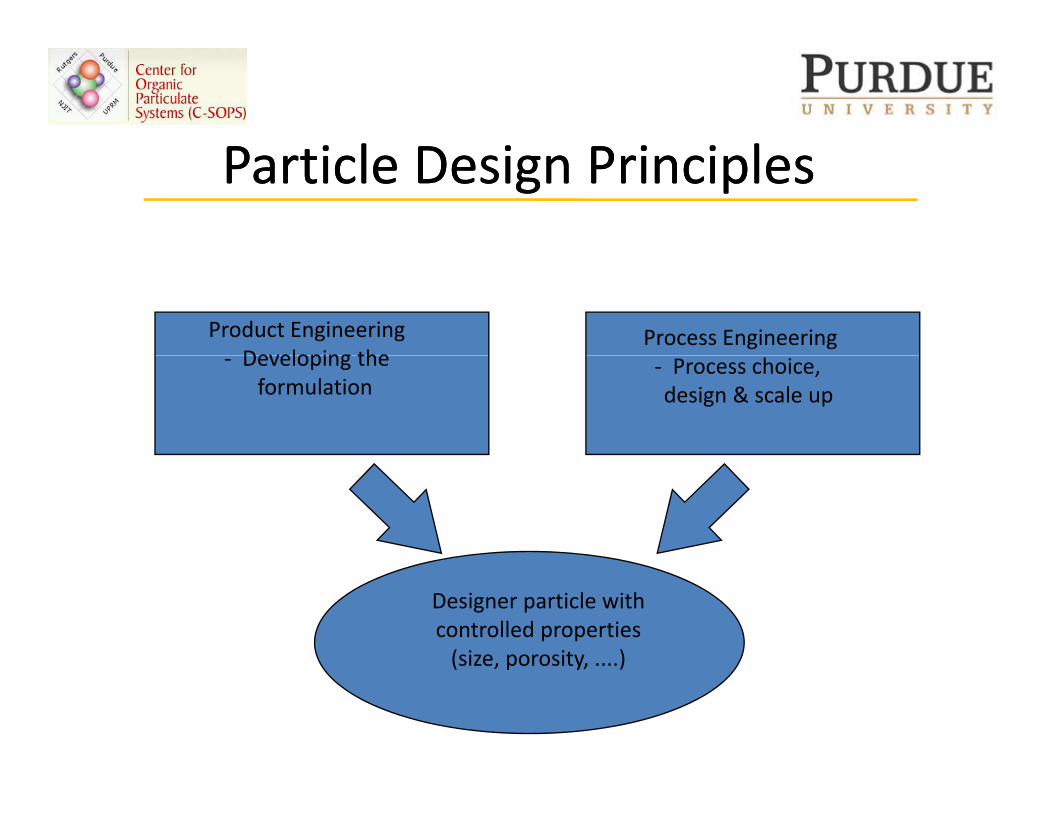
P ti l D i P i i lP ti l D i P i i lParticle Design PrinciplesParticle Design Principles
Product EngineeringDeveloping the
Process Engineering‐ Developing the
formulation‐ Process choice, design & scale up
Designer particle withcontrolled properties(size porosity )(size, porosity, ....)
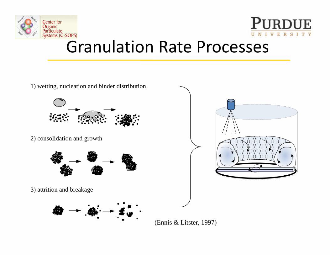
Granulation Rate ProcessesGranulation Rate Processes
1) wetting, nucleation and binder distribution
2) consolidation and growth
3) attrition and breakage
(Ennis & Litster, 1997)
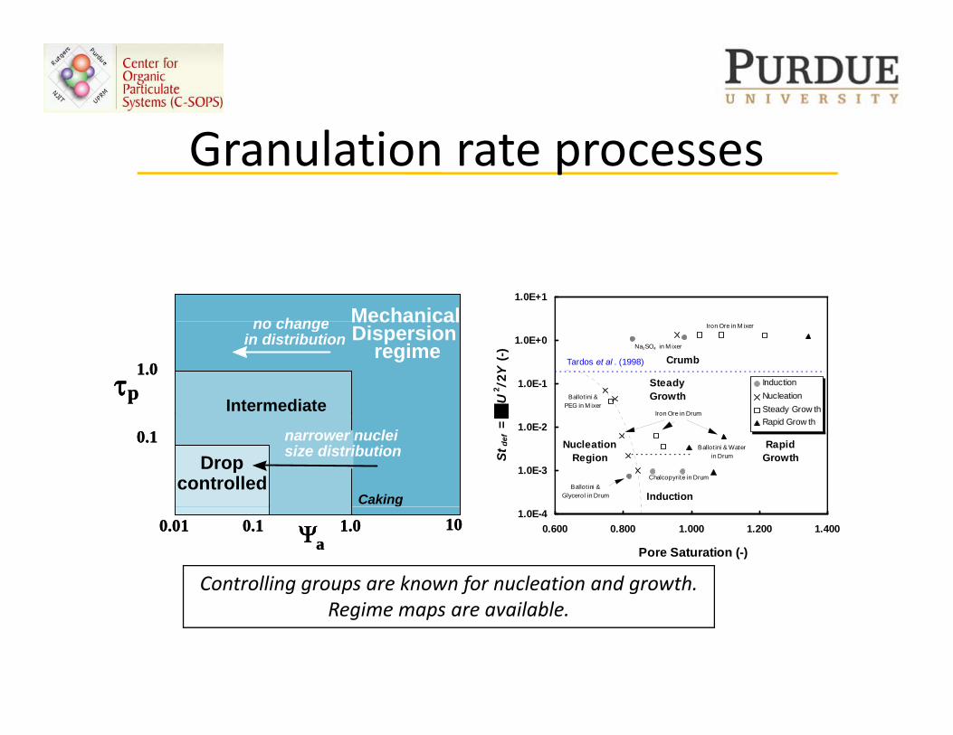
G l ti tGranulation rate processes
Mechanicalno change Mechanicalno change
1.0E+1
τp
MechanicalDispersion
regime
Intermediate
1.0
no changein distribution
τp
MechanicalDispersion
regime
Intermediate
1.0
no changein distribution
1.0E-1
1.0E+0
U2 /2
Y (-
)
InductionNucleationSteady Grow th
Steady Growth
Tardos et al . (1998) Crumb
Iron Ore in Drum
Ballot ini & PEG in M ixer
Iron Ore in M ixer
Na2SO4 in M ixer
Dropcontrolled
narrower nucleisize distribution
0.1
Caking
Dropcontrolled
narrower nucleisize distribution
0.1
Caking
1.0E-3
1.0E-2
Stde
f = Rapid Grow th
NucleationRegion
RapidGrowth
Induction
Chalcopyrite in Drum
Ballot ini & Water in Drum
Iron Ore in Drum
Ballot ini & Glycerol in Drum
Ψa0.01 0.1 1.0 10Ψa0.01 0.1 1.0 10
1.0E-40.600 0.800 1.000 1.200 1.400
Pore Saturation (-)
Controlling groups are known for nucleation and growth. Regime maps are available.
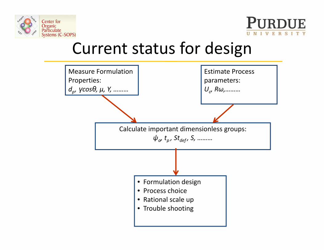
Current status for designCurrent status for designMeasure Formulation
iEstimate Process
Properties:dp, γcosθ, µ, Y, ………
parameters:Uc, Rω,………
Calculate important dimensionless groups:ψa, tp , Stdef , S, ………ψa, p , def , ,
• Formulation design• Process choice• Rational scale up• Trouble shooting
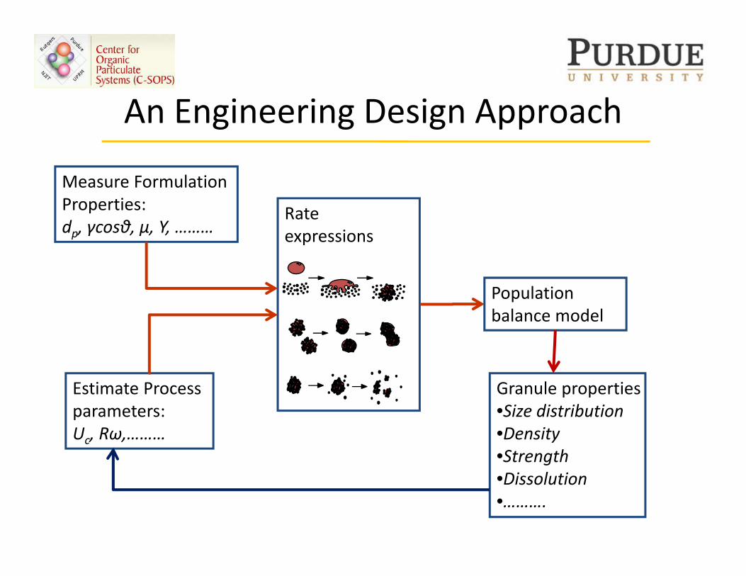
An Engineering Design ApproachAn Engineering Design Approach
Measure FormulationMeasure Formulation Properties:dp, γcosθ, µ, Y, ………
Rate expressions
Population balance model
Granule propertiesEstimate Process p p•Size distribution•Density•Strength
parameters:Uc, Rω,………
•Dissolution•……….
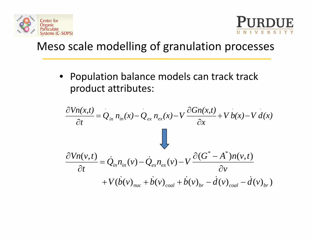
Meso scale modelling of granulation processesMeso scale modelling of granulation processes
• Pop lation balan e models an tra k tra k• Population balance models can track track product attributes:
(x)dV(x)bVx
t)Gn(x,V(x)nQ(x)nQt
t)Vn(x,exexinin
⋅⋅⋅⋅
−+∂
∂−−=
∂∂
),()()()(),( **
exexinintvnAGVvnQvnQtvVn &&
∂−∂
−−=∂
∂
))()()()()((
)()(
brcoalbrcoalnuc
exexinin
vdvdvbvbvbVv
QQt
&&&&& −−+++∂∂
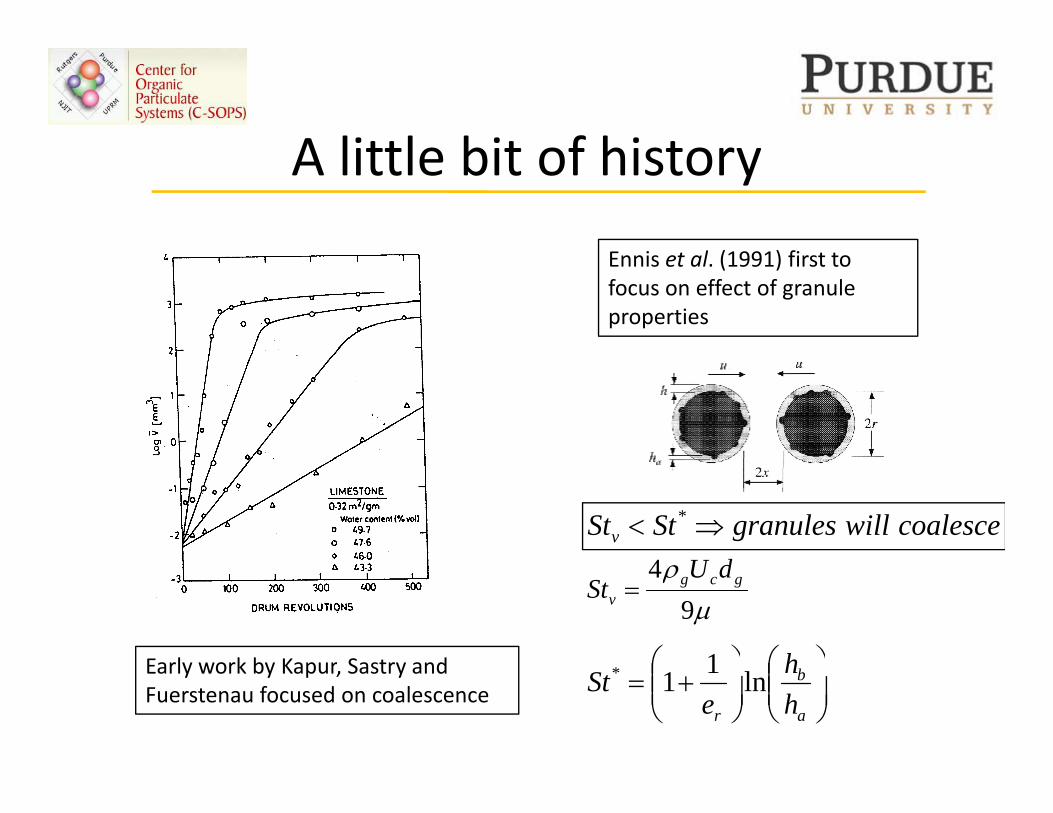
A little bit of historyA little bit of history
E i t l (1991) fi t tEnnis et al. (1991) first to focus on effect of granule properties
coalescewillgranulesStStv ⇒< *
4 dU
Early work by Kapur Sastry and
μρ
94 gcg
v
dUSt =
⎟⎞
⎜⎛
⎟⎞
⎜⎛ h1Early work by Kapur, Sastry and
Fuerstenau focused on coalescence ⎟⎟⎠
⎞⎜⎜⎝
⎛⎟⎟⎠
⎞⎜⎜⎝
⎛+=
a
b
r hh
eSt ln11*
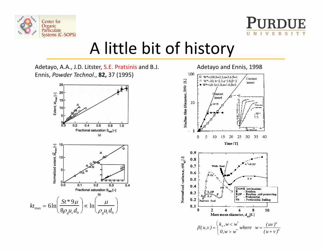
A little bit of historyA little bit of historyAdetayo, A.A., J.D. Litster, S.E. Pratsinis and B.J. Ennis, Powder Technol., 82, 37 (1995)
Adetayo and Ennis, 1998( )
k 6lSt * 9μ⎛
⎜ ⎞ ⎟ l
μ⎛ ⎜ ⎞
⎟ ktmax = 6lnμ
8ρgucd0⎝ ⎜
⎠ ⎟ ∝ ln
μρgucd0⎝
⎜ ⎠ ⎟
b
a
*
*o
)vu()uv(wwhere
ww,0ww,k
)v,u(+
=⎩⎨⎧
><
=β
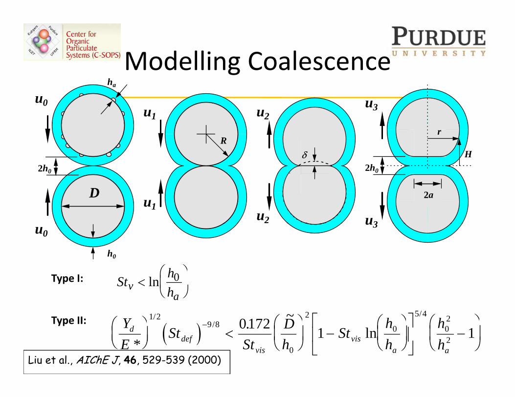
Modelling Coalescencegu0
u1 u2u3
ha
δ2h0
Rr
H2h0
D u1u2 u3
2a
u0u3
h0
h⎛ ⎞0St hhva
<⎛⎝⎜
⎞⎠⎟ln 0
( )Y D h h~//
/⎛ ⎞ ⎛ ⎞ ⎛ ⎞⎡ ⎤ ⎛ ⎞1 2
9 82 5 4 20172
Type I:
Type II:( )Y
ESt
StDh
Sthh
hh
ddef
visvis
a a*. ln
/⎛⎝⎜
⎞⎠⎟
<⎛⎝⎜
⎞⎠⎟ −
⎛⎝⎜
⎞⎠⎟
⎡
⎣⎢
⎤
⎦⎥ −
⎛
⎝⎜
⎞
⎠⎟
−9 8
0
0 02
0172 1 1Type II:
Liu et al., AIChE J, 46, 529-539 (2000)
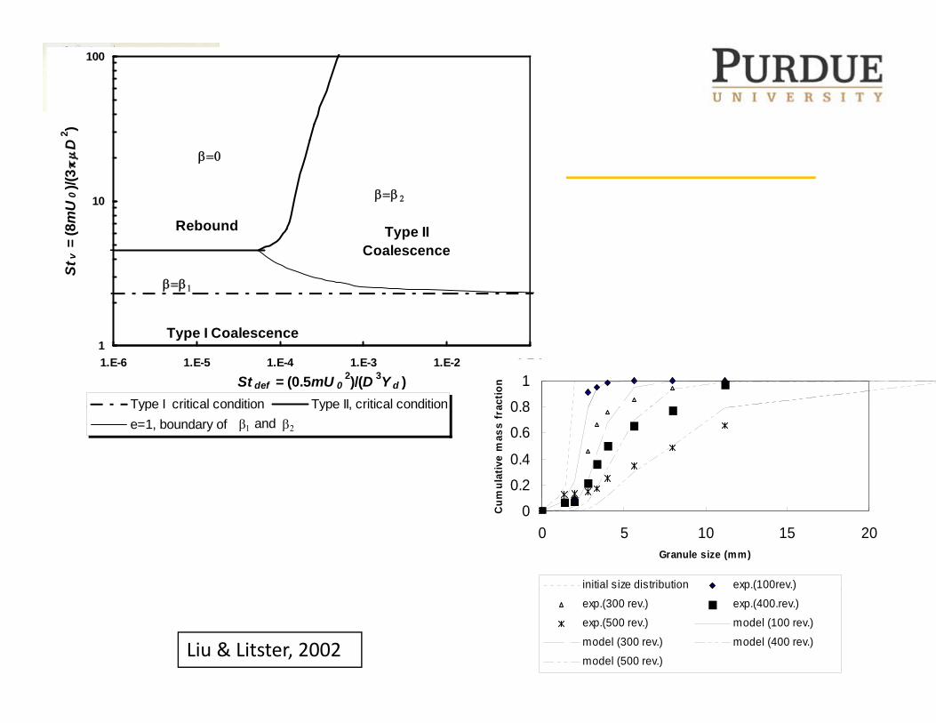
1002 )
10
8mU
0)/(
3D
2
Rebound
β=0
β=β 2
Stv
= (8 Type II
Coalescence
Rebound
β=β 1
11.E-6 1.E-5 1.E-4 1.E-3 1.E-2 1.E-1
St def = (0.5mU 02)/(D 3Y d )
Type I critical condition Type II, critical condition
Type I Coalescence
0 8
1
actio
n
Type I critical condition Type II, critical conditione=1, boundary of β1 and β2
0.2
0.4
0.6
0.8
mul
ativ
e m
ass
fra
00 5 10 15 20
Granule size (mm)
Cum
initial size distribution exp.(100rev.)p ( )
exp.(300 rev.) exp.(400.rev.)exp.(500 rev.) model (100 rev.)
model (300 rev.) model (400 rev.)
model (500 rev.)Liu & Litster, 2002
Multidimensional PB modelsMultidimensional PB models
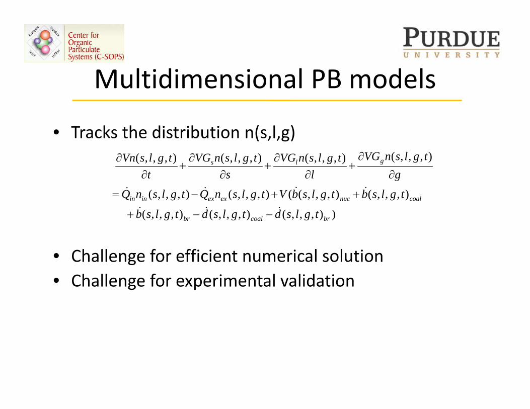
T k th di t ib ti ( l )• Tracks the distribution n(s,l,g)),,,(),,,(),,,(),,,( gls
gtglsnVG
ltglsnVG
stglsnVG
ttglsVn
∂
∂+
∂∂
+∂
∂+
∂∂
)),,,(),,,(),,,(
),,,(),,,((),,,(),,,(
brcoalbr
coalnucexexinin
tglsdtglsdtglsb
tglsbtglsbVtglsnQtglsnQg
&&&
&&&&
−−+
++−=
• Challenge for efficient numerical solution• Challenge for experimental validation• Challenge for experimental validation
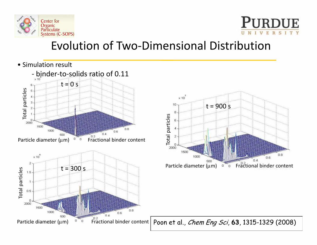
Evolution of Two Dimensional Distribution• Simulation result
‐ binder‐to‐solids ratio of 0.11
Evolution of Two‐Dimensional Distribution
binder to solids ratio of 0.11t = 0 s
t = 900 sparticles
t = 900 s
al particles
Total
F i l bi di l di ( )
29/10/2008t = 300 s
Tota
s Fractional binder content
Fractional binder contentParticle diameter (μm)
Particle diameter (μm)t = 300 s
Total particles
18Fractional binder contentParticle diameter (μm) Poon et al., Chem Eng Sci, 63, 1315-1329 (2008)
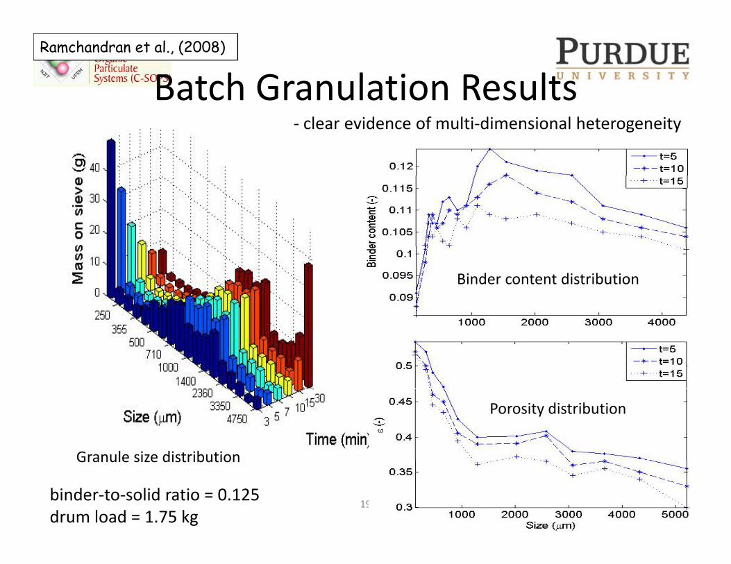
Batch Granulation ResultsRamchandran et al., (2008)
‐ clear evidence of multi‐dimensional heterogeneity
Binder content distribution
Granule size distribution
Porosity distribution
19 29/10/2008
Granule size distribution
binder‐to‐solid ratio = 0.125 drum load = 1.75 kg
• Multidimensional PB approaches:– allow incorporation of more physics in the rate expressions
– Track property distributions of interest to us
• But powder flow and particle interactions still represented in a crude, lumped parameter format
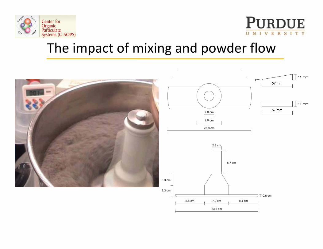
The impact of mixing and powder flowThe impact of mixing and powder flow
2.8 cm
7.0 cm
23.8 cm
2.8 cm
6.7 cm
7.0 cm8.4 cm 8.4 cm
0.6 cm
3.3 cm
3.3 cm
23.8 cm
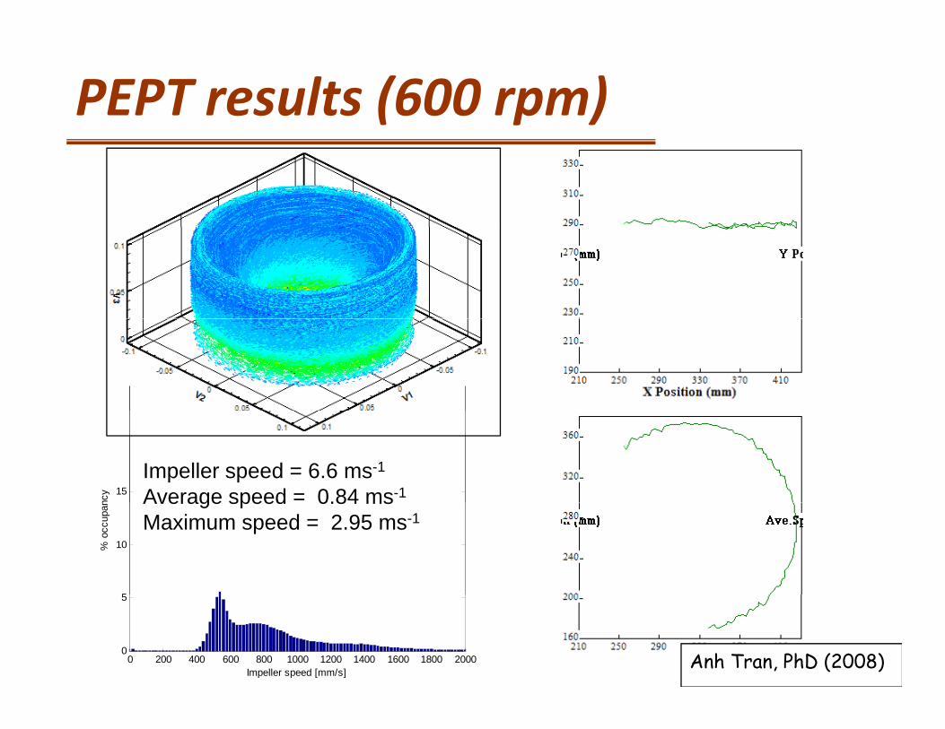
PEPT results (600 rpm)
15
ncy
Impeller speed = 6.6 ms-1
Average speed = 0.84 ms-1
5
10% o
ccup
an
Average speed 0.84 msMaximum speed = 2.95 ms-1
0 200 400 600 800 1000 1200 1400 1600 1800 20000
5
Impeller speed [mm/s]Anh Tran, PhD (2008)
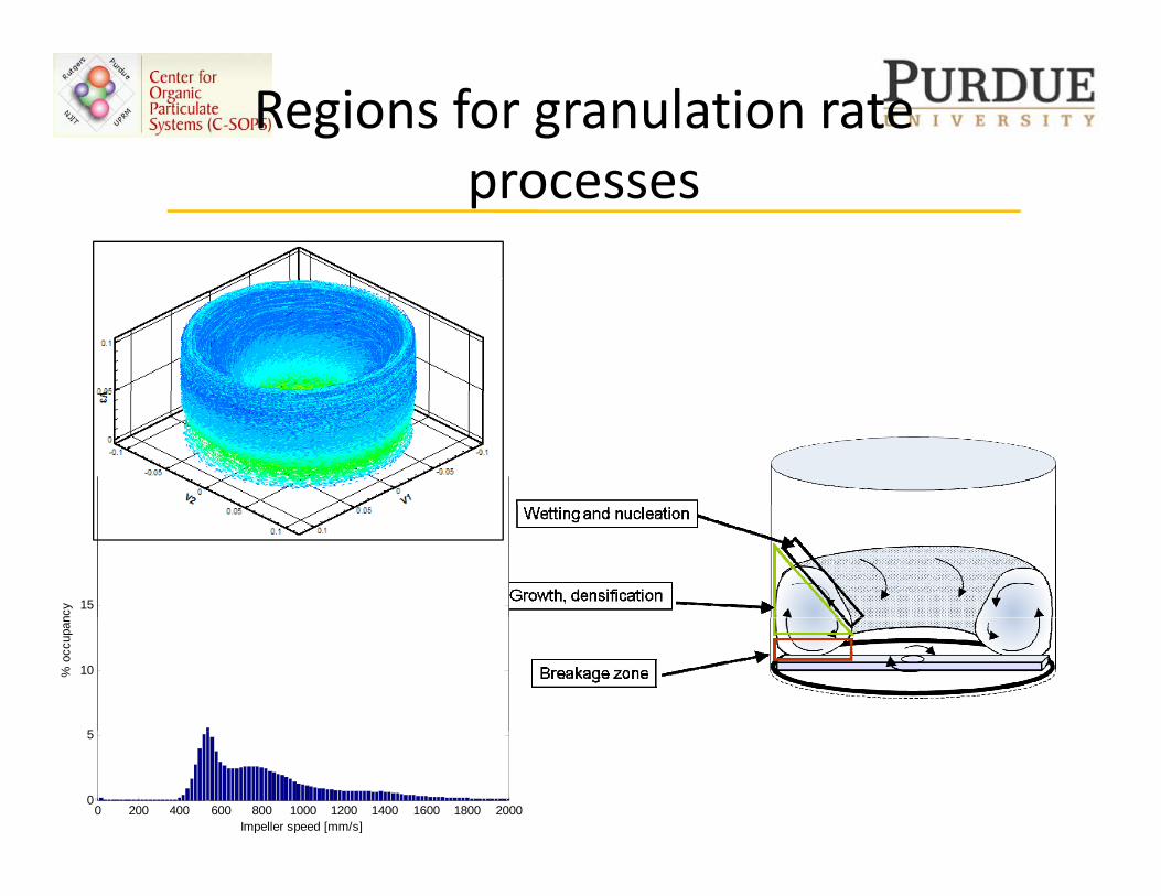
Regions for granulation rate processes
15
ncy
5
10% o
ccup
an
0 200 400 600 800 1000 1200 1400 1600 1800 20000
5
Impeller speed [mm/s]
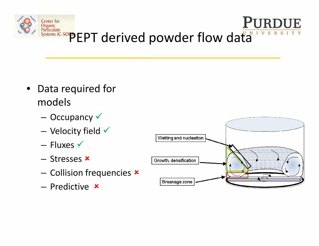
PEPT derived powder flow data
• Data required for models– Occupancy
– Velocity field
– Fluxes
– Stresses
C lli i f i– Collision frequencies
– Predictive
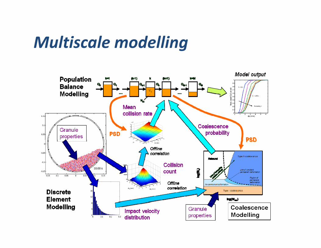
Multiscale modellingMultiscale modelling
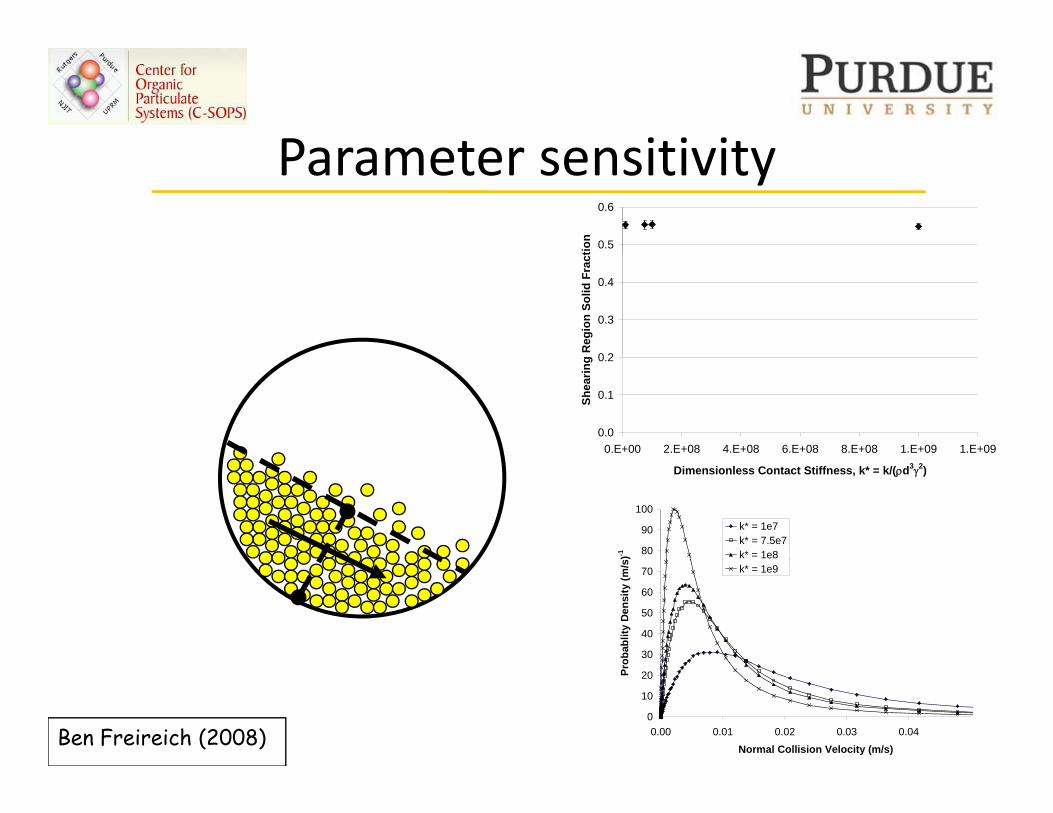
Parameter sensitivityParameter sensitivity0.5
0.6
tion
0 2
0.3
0.4
Reg
ion
Solid
Fra
ct
0.0
0.1
0.2
0.E+00 2.E+08 4.E+08 6.E+08 8.E+08 1.E+09 1.E+09
Shea
ring
Dimensionless Contact Stiffness, k* = k/(ρd3γ2)
80
90
100
s)-1
k* = 1e7k* = 7.5e7k* = 1e8
30
40
50
60
70
obab
lity
Den
sity
(m/s k* = 1e9
0
10
20
0.00 0.01 0.02 0.03 0.04
Normal Collision Velocity (m/s)
Pro
Ben Freireich (2008)
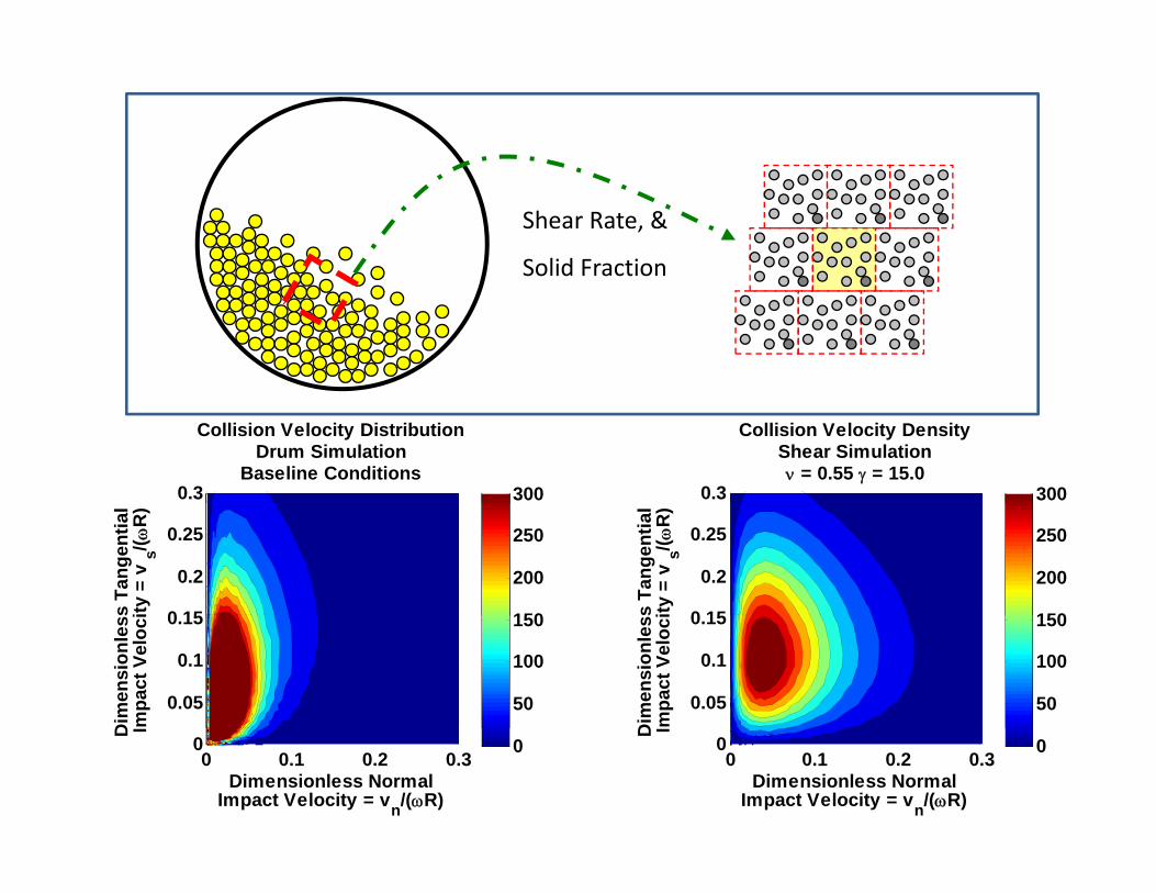
Shear Rate, &
Solid Fraction
Collision Velocity DistributionDrum Simulation
Baseline Conditions0.3 300
Collision Velocity DensityShear Simulationν = 0.55 γ = 15.0
0.3 300
s Ta
ngen
tial
ity =
vs/( ω
R)
0 15
0.2
0.25
150
200
250
s Ta
ngen
tial
ity =
vs/( ω
R)
0 15
0.2
0.25
150
200
250
Dim
ensi
onle
ssm
pact
Vel
oci
0.05
0.1
0.15
50
100
150D
imen
sion
less
mpa
ct V
eloc
i
0.05
0.1
0.15
50
100
150
Dimensionless NormalImpact Velocity = vn/(ωR)
D I
0 0.1 0.2 0.3
0 0
Dimensionless NormalImpact Velocity = vn/(ωR)
D I
0 0.1 0.2 0.3
0 0
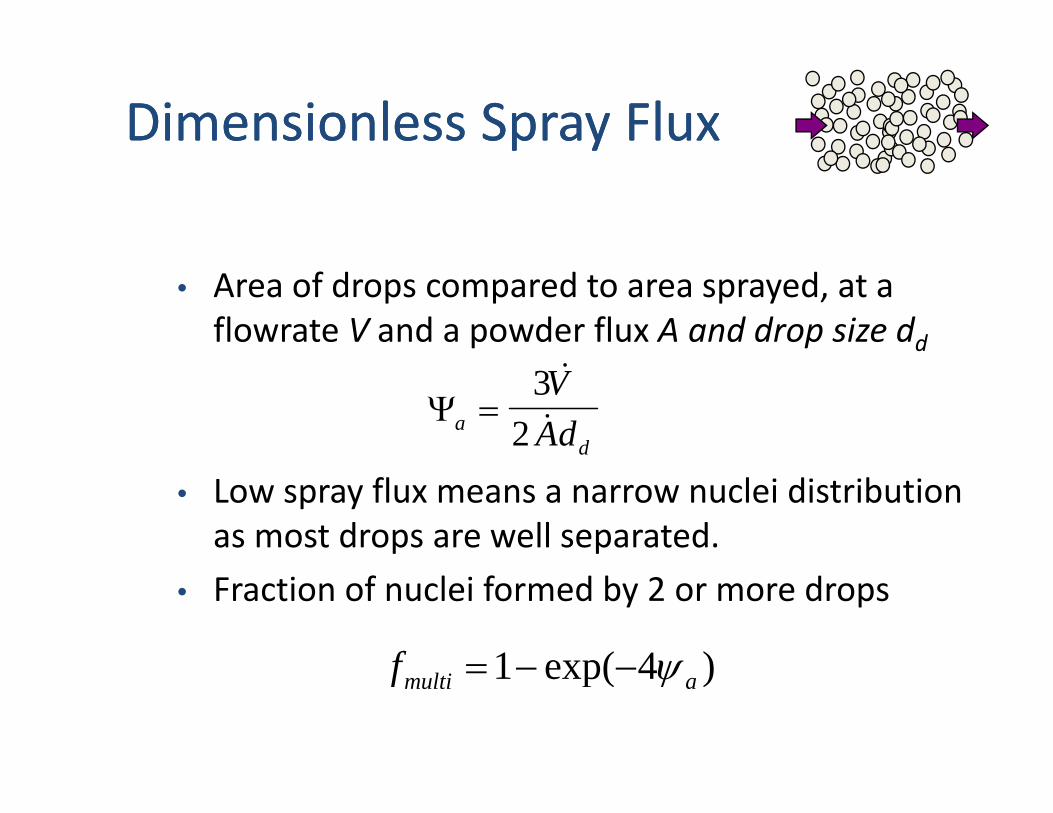
Dimensionless Spray FluxDimensionless Spray Fluxp yp y
• Area of drops compared to area sprayed, at a flowrate V and a powder flux A and drop size dd
Ψad
VAd
=3
2
&
&
• Low spray flux means a narrow nuclei distribution as most drops are well separated.
• Fraction of nuclei formed by 2 or more drops
)4exp(1f ψ )4exp(1 amultif ψ−−=
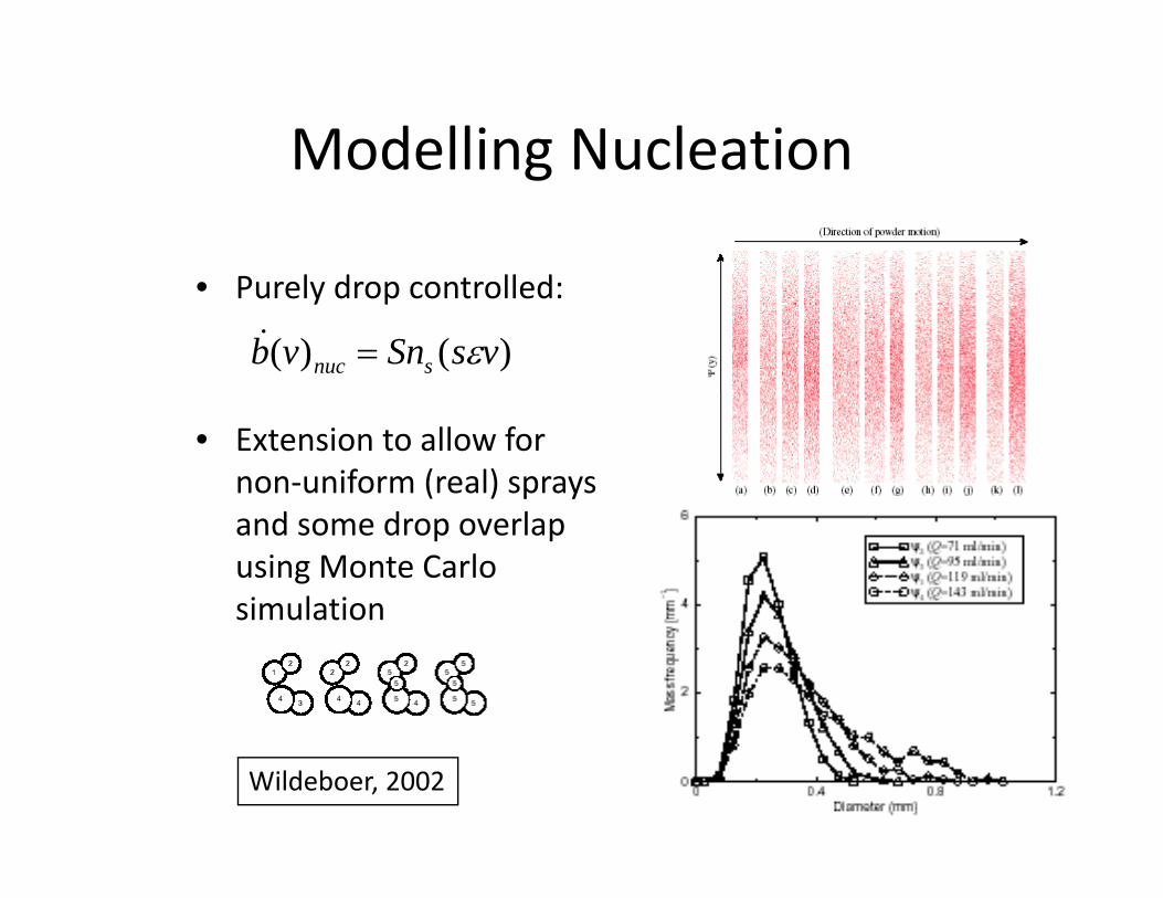
Modelling NucleationModelling Nucleation
P l d t ll d• Purely drop controlled:
)()( vsSnvb snuc ε=&
• Extension to allow for non‐uniform (real) sprays and some drop overlap using Monte Carlo simulationsimulation
Wildeboer, 2002
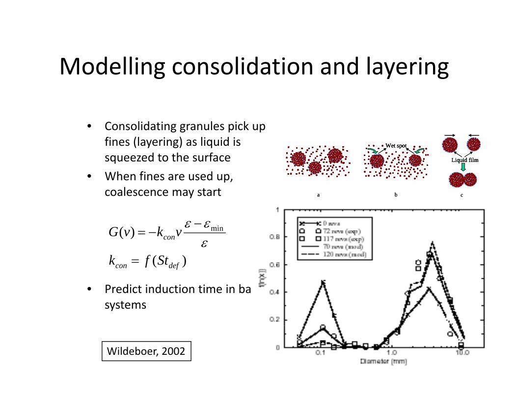
Modelling consolidation and layeringModelling consolidation and layering
• Consolidating granules pick up• Consolidating granules pick up fines (layering) as liquid is squeezed to the surface
• When fines are used up
Wet spot
Liquid film
Wet spotWet spot
Liquid filmLiquid film
• When fines are used up, coalescence may start a b ca b c
−εε
)(
)( min
defcon
con
Stfk
vkvG
=
−=εεε
• Predict induction time in batch systems
Wildeboer, 2002
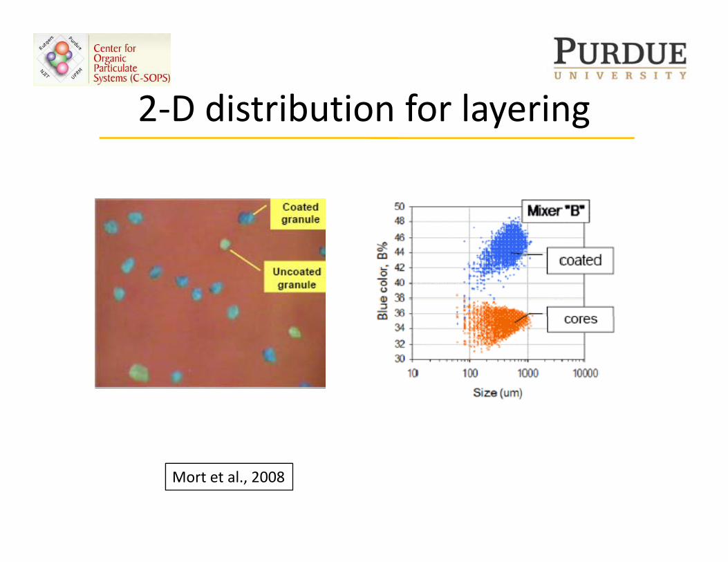
2 D distribution for layering2‐D distribution for layering
Mort et al., 2008
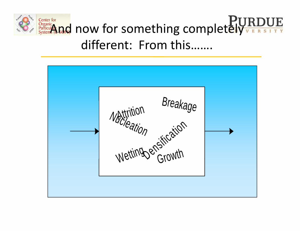
And now for something completely different From thisdifferent: From this…….
Bre kNucleation tion
BreakageAttrition
Wetting
ation
Densificatio
GrowthWe D Grow
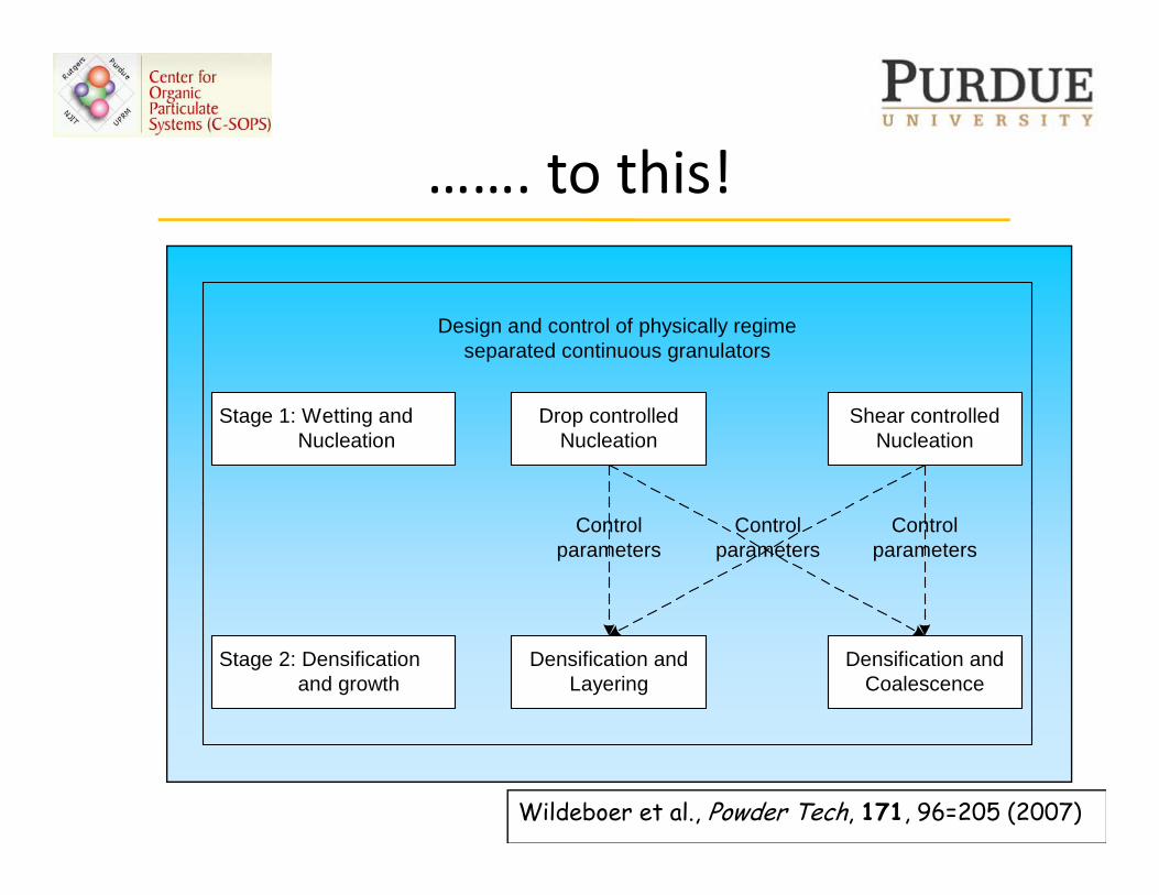
to this!……. to this!
Design and control of physically regimeseparated continuous granulators
Stage 1: Wetting and Nucleation
Drop controlledNucleation
Shear controlledNucleation
Controlparameters
Controlparameters
Controlparameters
Stage 2: Densification and growth
Densification andLayering
Densification andCoalescence
Wildeboer et al., Powder Tech, 171, 96=205 (2007)
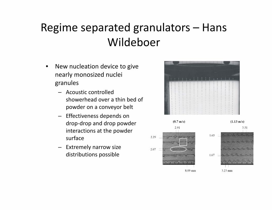
Regime separated granulators – Hans Wild bWildeboer
• New nucleation device to give• New nucleation device to give nearly monosized nuclei granules
Acoustic controlled– Acoustic controlled showerhead over a thin bed of powder on a conveyor belt
– Effectiveness depends on pdrop‐drop and drop powder interactions at the powder surface
l– Extremely narrow size distributions possible

SummarySummary