Embed Size (px)
Citation preview
Pop-up SLAM: Semantic Monocular Plane SLAMfor Low-texture Environments
Shichao Yang, Yu Song, Michael Kaess, and Sebastian Scherer
Abstract— Existing simultaneous localization and mapping(SLAM) algorithms are not robust in challenging low-textureenvironments because there are only few salient features.The resulting sparse or semi-dense map also conveys littleinformation for motion planning. Though some work utilizeplane or scene layout for dense map regularization, they requiredecent state estimation from other sources. In this paper, wepropose real-time monocular plane SLAM to demonstrate thatscene understanding could improve both state estimation anddense mapping especially in low-texture environments. Theplane measurements come from a pop-up 3D plane modelapplied to each single image. We also combine planes with pointbased SLAM to improve robustness. On a public TUM dataset,our algorithm generates a dense semantic 3D model with pixeldepth error of 6.2 cm while existing SLAM algorithms fail. Ona 60 m long dataset with loops, our method creates a muchbetter 3D model with state estimation error of 0.67%.
I. INTRODUCTION
Simultaneous localization and mapping (SLAM) is widelyused for tasks including autonomous navigation, 3D mappingand inspection. Various sensors can be used for SLAM suchas laser-range finders cameras, and RGB-D depth cameras.Monocular cameras are a popular choice of sensor on robotsas they can provide rich visual information at a smallsize and low cost. They are especially suitable for weightconstrained micro aerial vehicles that can carry only onecamera. Therefore, in this work we focus on using monocularimages to estimate the pose and map of the environment.
On one hand, many existing visual SLAM methods utilizepoint features such as direct LSD SLAM [1] and featurebased ORB SLAM [2]. These methods track features or high-gradient pixels across frames to find correspondences andtriangulate depth. They usually perform well in environmentswith rich features but cannot work well in low-texturescenes as often found in corridors. In addition, the map isusually sparse or semi-dense, which does not convey muchinformation for motion planning.
On the other hand, humans can understand the layout,estimate depth and detect obstacles from a single image.Many methods have been proposed to exploit the geometrycues and scene assumption in order to build a simplified3D model. Especially in recent years, with the advent ofConvolutional Neural Networks (CNN) [3], performance ofvisual understanding has been greatly increased.
In this paper, we combine scene understanding withtraditional v-SLAM to increase the performance of both
The Robotics Institute, Carnegie Mellon University, 5000 ForbesAve, Pittsburgh, PA 15213, USA. {shichaoy, songyu, kaess,basti}@andrew.cmu.edu
Fig. 1. 3D reconstruction on low-texture TUM dataset. (top) Single frame,raw image on left and 3D pop-up plane model on right. (center) Densereconstruction using our Pop-up Plane SLAM. Each plane has a label ofeither a specific wall or ground. (bottom) Top view of the 3D model. Existingstate-of-art SLAM algorithms fail.
state estimation and dense mapping especially in low-textureenvironments. We use a single image pop-up plane model [4]to generate plane landmark measurements in SLAM. Withproper plane association and loop closing, we are able tojointly optimize scene layout and poses of multiple framesin the SLAM framework. In the low-texture environmentof Figure 1, our algorithm can still generate dense 3Dmodels and decent state estimates while other state-of-the-artalgorithms fail. However, plane SLAM can easily be under-constrained, hence we propose to combine it with traditionalpoint-based LSD SLAM [1] to increase robustness.
In summary, our main contributions are:
• A real-time monocular plane SLAM system incorporat-ing scene layout understanding,
• Integrate planes with point-based SLAM for robustness,• Outperform existing methods especially in some low-
texture environments and demonstrate the practicabilityon several large datasets with loops.
In the following section, we discuss related work. SectionIII describes the single image layout understanding, whichprovides plane measurements for plane SLAM. In SectionIV, we introduce the Pop-up Plane SLAM formulation and
arX
iv:1
703.
0733
4v1
[cs
.CV
] 2
1 M
ar 2
017
combine it with LSD SLAM in Section V. Experiments ona public TUM dataset and actual indoor environments arepresented in Section VI. Finally, we conclude in Section VII.
II. RELATED WORK
Our approach combines aspects of two research areas:single image scene understanding and multiple images visualSLAM. We provide a brief overview of these two area.
A. Single Image
There are many methods that attempt to model theworld from a single image. Two representative examples arecuboidal room box model proposed based on vanishing pointby Hedau et al. [5] and fixed building model collectionsbased on line segments by Lee et al. [6]. Our previouswork [4] proposed the pop-up 3D plane model, combiningCNNs with geometry modeling. Results show that our workis more robust to various corridor configurations and lightingconditions than existing methods.
B. Multiple Images
1) v-SLAM using points: Structure from Motion and v-SLAM have been widely used to obtain 3D reconstructionsfrom images [7]. These methods track image features acrossmultiple frames and build a globally consistent 3D map usingoptimization. Two representatives of them are direct LSDSLAM [1] and feature- based ORB SLAM [2]. But thesemethods work poorly in low-texture environments becauseof the sparse visual and geometric features.
2) v-SLAM using planes: Planes or superpixels have beenused in [8]–[10] to provide dense mapping in low-textureareas. But they assume camera poses are provided fromother sources such as point based SLAM, which may notwork well in textureless environments as mentioned above.Recently, Concha et al. [11] also propose to use room layoutinformation to generate depth priors for dense mappinghowever they don’t track and update the room layout thuscan only work in small workspace.
3) Scene understanding: Some works focus on the sceneunderstanding using multiple images, especially in a Man-hattan world. Flint et al. [12] formulate it as Bayesianframework using monocular and 3D features. [13], [14] gen-erate many candidate 3D model hypotheses and subsequentlyupdate their probability by feature tracking and point cloudmatching. Unfortunately, these methods do not use a planeworld to constrain the state estimation and thus cannot solvethe problem of v-SLAM in low-texture environments.
III. SINGLE IMAGE PLANE POP-UP
This section extends our previous work [4] to create apop-up 3D plane model from a single image. We first brieflyrecap the previous work, discuss its limitation, and proposetwo improvements accordingly.
A. Pop-up 3D Model
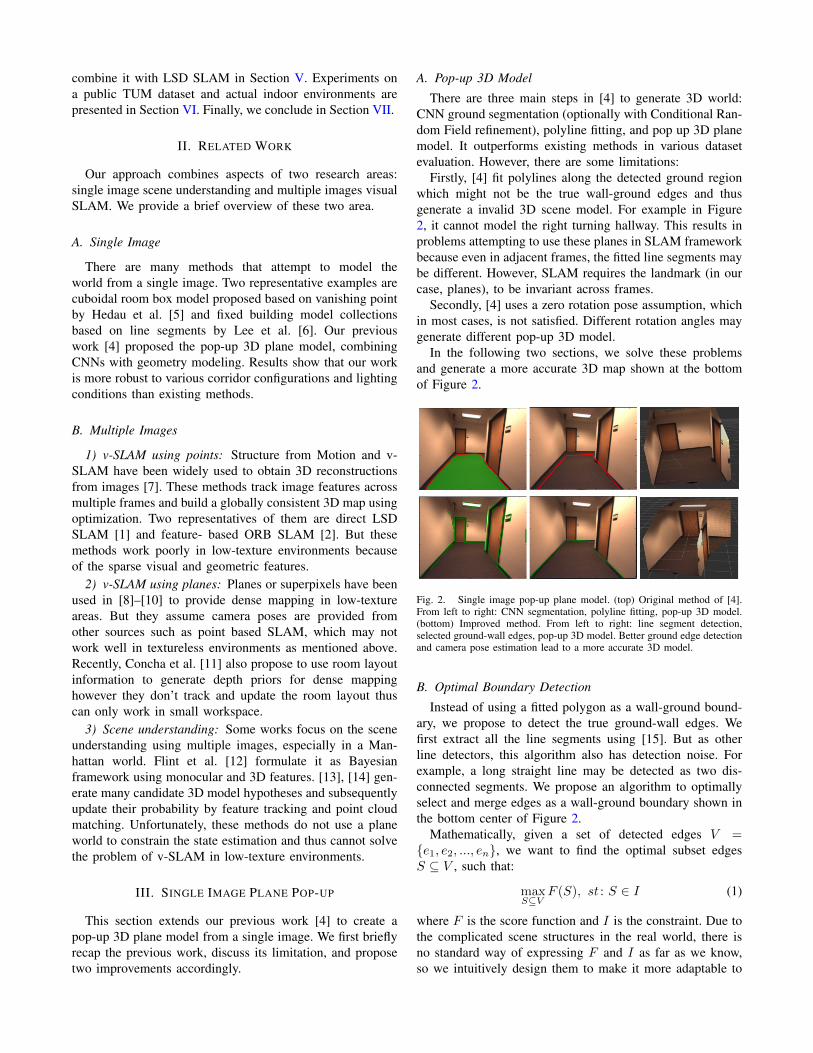
There are three main steps in [4] to generate 3D world:CNN ground segmentation (optionally with Conditional Ran-dom Field refinement), polyline fitting, and pop up 3D planemodel. It outperforms existing methods in various datasetevaluation. However, there are some limitations:
Firstly, [4] fit polylines along the detected ground regionwhich might not be the true wall-ground edges and thusgenerate a invalid 3D scene model. For example in Figure2, it cannot model the right turning hallway. This results inproblems attempting to use these planes in SLAM frameworkbecause even in adjacent frames, the fitted line segments maybe different. However, SLAM requires the landmark (in ourcase, planes), to be invariant across frames.
Secondly, [4] uses a zero rotation pose assumption, whichin most cases, is not satisfied. Different rotation angles maygenerate different pop-up 3D model.
In the following two sections, we solve these problemsand generate a more accurate 3D map shown at the bottomof Figure 2.
Fig. 2. Single image pop-up plane model. (top) Original method of [4].From left to right: CNN segmentation, polyline fitting, pop-up 3D model.(bottom) Improved method. From left to right: line segment detection,selected ground-wall edges, pop-up 3D model. Better ground edge detectionand camera pose estimation lead to a more accurate 3D model.
B. Optimal Boundary Detection
Instead of using a fitted polygon as a wall-ground bound-ary, we propose to detect the true ground-wall edges. Wefirst extract all the line segments using [15]. But as otherline detectors, this algorithm also has detection noise. Forexample, a long straight line may be detected as two dis-connected segments. We propose an algorithm to optimallyselect and merge edges as a wall-ground boundary shown inthe bottom center of Figure 2.
Mathematically, given a set of detected edges V ={e1, e2, ..., en}, we want to find the optimal subset edgesS ⊆ V , such that:
maxS⊆V
F (S), st : S ∈ I (1)
where F is the score function and I is the constraint. Due tothe complicated scene structures in the real world, there isno standard way of expressing F and I as far as we know,so we intuitively design them to make it more adaptable to
various environments, not limited to a Manhattan world asit is typically done in many current approaches [11] [13].
The first constraint indicates that edges should be closeto the CNN detected boundary curve ξ within a thresholdshown as red curve in the top left of Figure 2. It can bedenoted as:
Iclose = {S : ∀e ∈ S, dist(e, ξ) < δclose} (2)
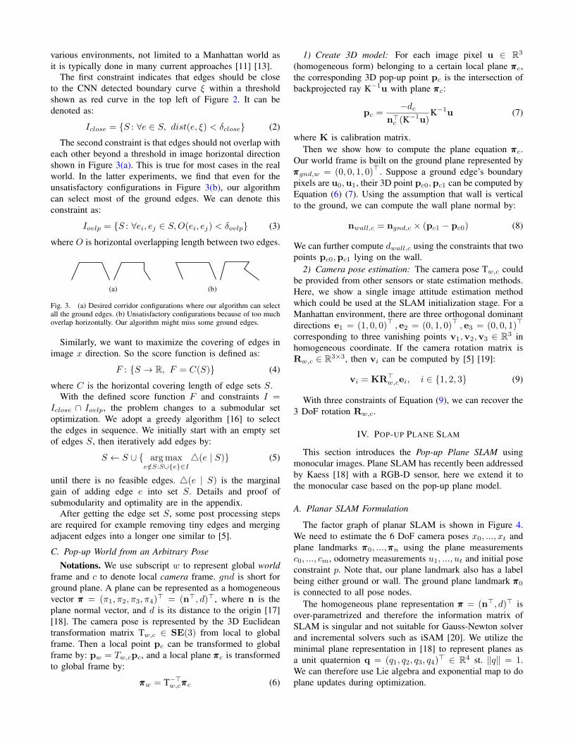
The second constraint is that edges should not overlap witheach other beyond a threshold in image horizontal directionshown in Figure 3(a). This is true for most cases in the realworld. In the latter experiments, we find that even for theunsatisfactory configurations in Figure 3(b), our algorithmcan select most of the ground edges. We can denote thisconstraint as:
Iovlp = {S : ∀ei, ej ∈ S,O(ei, ej) < δovlp} (3)
where O is horizontal overlapping length between two edges.
(a) (b)
Fig. 3. (a) Desired corridor configurations where our algorithm can selectall the ground edges. (b) Unsatisfactory configurations because of too muchoverlap horizontally. Our algorithm might miss some ground edges.
Similarly, we want to maximize the covering of edges inimage x direction. So the score function is defined as:
F : {S → R, F = C(S)} (4)
where C is the horizontal covering length of edge sets S.With the defined score function F and constraints I =
Iclose ∩ Iovlp, the problem changes to a submodular setoptimization. We adopt a greedy algorithm [16] to selectthe edges in sequence. We initially start with an empty setof edges S, then iteratively add edges by:
S ← S ∪ { arg maxe/∈S:S∪{e}∈I
4(e | S)} (5)
until there is no feasible edges. 4(e | S) is the marginalgain of adding edge e into set S. Details and proof ofsubmodularity and optimality are in the appendix.
After getting the edge set S, some post processing stepsare required for example removing tiny edges and mergingadjacent edges into a longer one similar to [5].
C. Pop-up World from an Arbitrary PoseNotations. We use subscript w to represent global world
frame and c to denote local camera frame. gnd is short forground plane. A plane can be represented as a homogeneousvector πππ = (π1, π2, π3, π4)> = (n>, d)>, where n is theplane normal vector, and d is its distance to the origin [17][18]. The camera pose is represented by the 3D Euclideantransformation matrix Tw,c ∈ SE(3) from local to globalframe. Then a local point pc can be transformed to globalframe by: pw = Tw,cpc, and a local plane πππc is transformedto global frame by:
πππw = T−>w,cπππc (6)
1) Create 3D model: For each image pixel u ∈ R3
(homogeneous form) belonging to a certain local plane πππc,the corresponding 3D pop-up point pc is the intersection ofbackprojected ray K−1u with plane πππc:
pc =−dc
n>c (K−1u)K−1u (7)
where K is calibration matrix.Then we show how to compute the plane equation πππc.
Our world frame is built on the ground plane represented byπππgnd,w = (0, 0, 1, 0)
>. Suppose a ground edge’s boundarypixels are u0,u1, their 3D point pc0,pc1 can be computed byEquation (6) (7). Using the assumption that wall is verticalto the ground, we can compute the wall plane normal by:
nwall,c = ngnd,c × (pc1 − pc0) (8)
We can further compute dwall,c using the constraints that twopoints pc0,pc1 lying on the wall.
2) Camera pose estimation: The camera pose Tw,c couldbe provided from other sensors or state estimation methods.Here, we show a single image attitude estimation methodwhich could be used at the SLAM initialization stage. For aManhattan environment, there are three orthogonal dominantdirections e1 = (1, 0, 0)
>, e2 = (0, 1, 0)
>, e3 = (0, 0, 1)
>
corresponding to three vanishing points v1,v2,v3 ∈ R3 inhomogeneous coordinate. If the camera rotation matrix isRw,c ∈ R3×3, then vi can be computed by [5] [19]:
vi = KR>w,cei, i ∈ {1, 2, 3} (9)
With three constraints of Equation (9), we can recover the3 DoF rotation Rw,c.
IV. POP-UP PLANE SLAM
This section introduces the Pop-up Plane SLAM usingmonocular images. Plane SLAM has recently been addressedby Kaess [18] with a RGB-D sensor, here we extend it tothe monocular case based on the pop-up plane model.
A. Planar SLAM Formulation
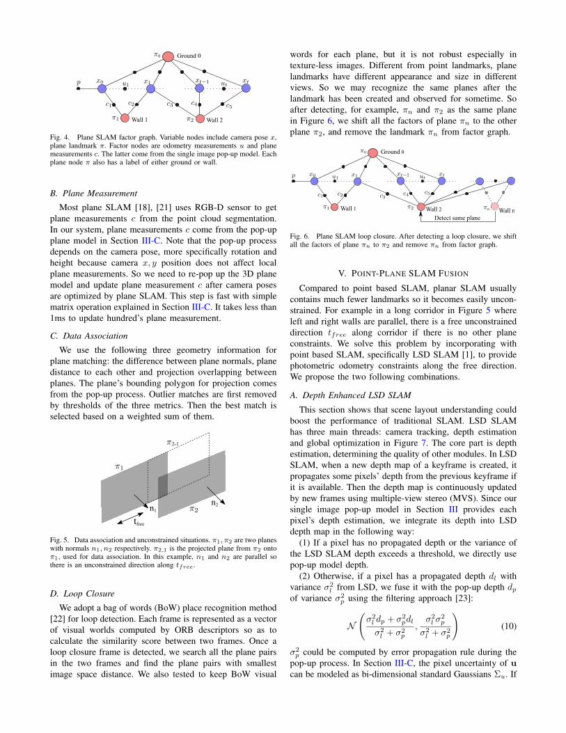
The factor graph of planar SLAM is shown in Figure 4.We need to estimate the 6 DoF camera poses x0, ..., xt andplane landmarks πππ0, ...,πππn using the plane measurementsc0, ..., cm, odometry measurements u1, ..., ut and initial poseconstraint p. Note that, our plane landmark also has a labelbeing either ground or wall. The ground plane landmark πππ0
is connected to all pose nodes.The homogeneous plane representation πππ = (n>, d)> is
over-parametrized and therefore the information matrix ofSLAM is singular and not suitable for Gauss-Newton solverand incremental solvers such as iSAM [20]. We utilize theminimal plane representation in [18] to represent planes asa unit quaternion q = (q1, q2, q3, q4)> ∈ R4 st. ‖q‖ = 1.We can therefore use Lie algebra and exponential map to doplane updates during optimization.
Wall 1 Wall 2
Ground 00
Fig. 4. Plane SLAM factor graph. Variable nodes include camera pose x,plane landmark π. Factor nodes are odometry measurements u and planemeasurements c. The latter come from the single image pop-up model. Eachplane node π also has a label of either ground or wall.
B. Plane Measurement
Most plane SLAM [18], [21] uses RGB-D sensor to getplane measurements c from the point cloud segmentation.In our system, plane measurements c come from the pop-upplane model in Section III-C. Note that the pop-up processdepends on the camera pose, more specifically rotation andheight because camera x, y position does not affect localplane measurements. So we need to re-pop up the 3D planemodel and update plane measurement c after camera posesare optimized by plane SLAM. This step is fast with simplematrix operation explained in Section III-C. It takes less than1ms to update hundred’s plane measurement.
C. Data Association
We use the following three geometry information forplane matching: the difference between plane normals, planedistance to each other and projection overlapping betweenplanes. The plane’s bounding polygon for projection comesfrom the pop-up process. Outlier matches are first removedby thresholds of the three metrics. Then the best match isselected based on a weighted sum of them.
n1n2
tfree
2-1
Fig. 5. Data association and unconstrained situations. π1, π2 are two planeswith normals n1, n2 respectively. π2 1 is the projected plane from π2 ontoπ1, used for data association. In this example, n1 and n2 are parallel sothere is an unconstrained direction along tfree.
D. Loop Closure
We adopt a bag of words (BoW) place recognition method[22] for loop detection. Each frame is represented as a vectorof visual worlds computed by ORB descriptors so as tocalculate the similarity score between two frames. Once aloop closure frame is detected, we search all the plane pairsin the two frames and find the plane pairs with smallestimage space distance. We also tested to keep BoW visual
words for each plane, but it is not robust especially intexture-less images. Different from point landmarks, planelandmarks have different appearance and size in differentviews. So we may recognize the same planes after thelandmark has been created and observed for sometime. Soafter detecting, for example, πn and π2 as the same planein Figure 6, we shift all the factors of plane πn to the otherplane π2, and remove the landmark πn from factor graph.
Wall 1 Wall 2
Ground 00
Wall nDetect same plane
n
Fig. 6. Plane SLAM loop closure. After detecting a loop closure, we shiftall the factors of plane πn to π2 and remove πn from factor graph.
V. POINT-PLANE SLAM FUSION
Compared to point based SLAM, planar SLAM usuallycontains much fewer landmarks so it becomes easily uncon-strained. For example in a long corridor in Figure 5 whereleft and right walls are parallel, there is a free unconstraineddirection tfree along corridor if there is no other planeconstraints. We solve this problem by incorporating withpoint based SLAM, specifically LSD SLAM [1], to providephotometric odometry constraints along the free direction.We propose the two following combinations.
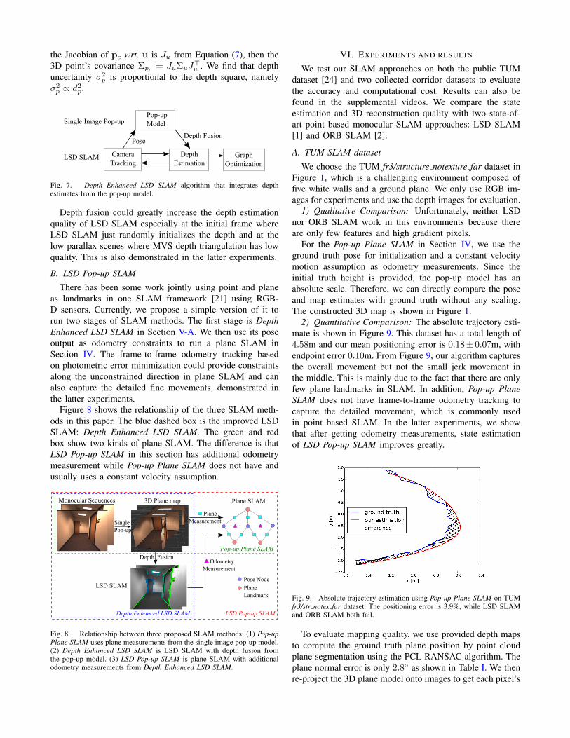
A. Depth Enhanced LSD SLAM
This section shows that scene layout understanding couldboost the performance of traditional SLAM. LSD SLAMhas three main threads: camera tracking, depth estimationand global optimization in Figure 7. The core part is depthestimation, determining the quality of other modules. In LSDSLAM, when a new depth map of a keyframe is created, itpropagates some pixels’ depth from the previous keyframe ifit is available. Then the depth map is continuously updatedby new frames using multiple-view stereo (MVS). Since oursingle image pop-up model in Section III provides eachpixel’s depth estimation, we integrate its depth into LSDdepth map in the following way:
(1) If a pixel has no propagated depth or the variance ofthe LSD SLAM depth exceeds a threshold, we directly usepop-up model depth.
(2) Otherwise, if a pixel has a propagated depth dl withvariance σ2
l from LSD, we fuse it with the pop-up depth dpof variance σ2
p using the filtering approach [23]:
N
(σ2l dp + σ2
pdl
σ2l + σ2
p
,σ2l σ
2p
σ2l + σ2
p
)(10)
σ2p could be computed by error propagation rule during the
pop-up process. In Section III-C, the pixel uncertainty of ucan be modeled as bi-dimensional standard Gaussians Σu. If
the Jacobian of pc wrt. u is Ju from Equation (7), then the3D point’s covariance Σpc = JuΣuJ
>u . We find that depth
uncertainty σ2p is proportional to the depth square, namely
σ2p ∝ d2p.
Camera Tracking
GraphOptimization
DepthEstimation
Pop-upModel
PoseDepth Fusion
LSD SLAM
Single Image Pop-up
Fig. 7. Depth Enhanced LSD SLAM algorithm that integrates depthestimates from the pop-up model.
Depth fusion could greatly increase the depth estimationquality of LSD SLAM especially at the initial frame whereLSD SLAM just randomly initializes the depth and at thelow parallax scenes where MVS depth triangulation has lowquality. This is also demonstrated in the latter experiments.
B. LSD Pop-up SLAM
There has been some work jointly using point and planeas landmarks in one SLAM framework [21] using RGB-D sensors. Currently, we propose a simple version of it torun two stages of SLAM methods. The first stage is DepthEnhanced LSD SLAM in Section V-A. We then use its poseoutput as odometry constraints to run a plane SLAM inSection IV. The frame-to-frame odometry tracking basedon photometric error minimization could provide constraintsalong the unconstrained direction in plane SLAM and canalso capture the detailed fine movements, demonstrated inthe latter experiments.
Figure 8 shows the relationship of the three SLAM meth-ods in this paper. The blue dashed box is the improved LSDSLAM: Depth Enhanced LSD SLAM. The green and redbox show two kinds of plane SLAM. The difference is thatLSD Pop-up SLAM in this section has additional odometrymeasurement while Pop-up Plane SLAM does not have andusually uses a constant velocity assumption.
Single Pop-up
Monocular Sequences 3D Plane map Plane SLAM
PlaneMeasurement
OdometryMeasurement
Depth Fusion
LSD SLAM
Depth Enhanced LSD SLAM LSD Pop-up SLAM
Pop-up Plane SLAM
Pose Node
PlaneLandmark
Fig. 8. Relationship between three proposed SLAM methods: (1) Pop-upPlane SLAM uses plane measurements from the single image pop-up model.(2) Depth Enhanced LSD SLAM is LSD SLAM with depth fusion fromthe pop-up model. (3) LSD Pop-up SLAM is plane SLAM with additionalodometry measurements from Depth Enhanced LSD SLAM.
VI. EXPERIMENTS AND RESULTS
We test our SLAM approaches on both the public TUMdataset [24] and two collected corridor datasets to evaluatethe accuracy and computational cost. Results can also befound in the supplemental videos. We compare the stateestimation and 3D reconstruction quality with two state-of-art point based monocular SLAM approaches: LSD SLAM[1] and ORB SLAM [2].
A. TUM SLAM dataset
We choose the TUM fr3/structure notexture far dataset inFigure 1, which is a challenging environment composed offive white walls and a ground plane. We only use RGB im-ages for experiments and use the depth images for evaluation.
1) Qualitative Comparison: Unfortunately, neither LSDnor ORB SLAM work in this environments because thereare only few features and high gradient pixels.
For the Pop-up Plane SLAM in Section IV, we use theground truth pose for initialization and a constant velocitymotion assumption as odometry measurements. Since theinitial truth height is provided, the pop-up model has anabsolute scale. Therefore, we can directly compare the poseand map estimates with ground truth without any scaling.The constructed 3D map is shown in Figure 1.
2) Quantitative Comparison: The absolute trajectory esti-mate is shown in Figure 9. This dataset has a total length of4.58m and our mean positioning error is 0.18± 0.07m, withendpoint error 0.10m. From Figure 9, our algorithm capturesthe overall movement but not the small jerk movement inthe middle. This is mainly due to the fact that there are onlyfew plane landmarks in SLAM. In addition, Pop-up PlaneSLAM does not have frame-to-frame odometry tracking tocapture the detailed movement, which is commonly usedin point based SLAM. In the latter experiments, we showthat after getting odometry measurements, state estimationof LSD Pop-up SLAM improves greatly.
Fig. 9. Absolute trajectory estimation using Pop-up Plane SLAM on TUMfr3/str notex far dataset. The positioning error is 3.9%, while LSD SLAMand ORB SLAM both fail.
To evaluate mapping quality, we use provided depth mapsto compute the ground truth plane position by point cloudplane segmentation using the PCL RANSAC algorithm. Theplane normal error is only 2.8◦ as shown in Table I. We thenre-project the 3D plane model onto images to get each pixel’s
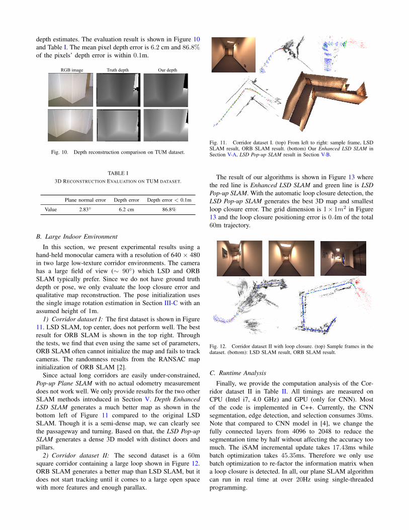
depth estimates. The evaluation result is shown in Figure 10and Table I. The mean pixel depth error is 6.2 cm and 86.8%of the pixels’ depth error is within 0.1m.
Our depthTruth depthRGB image
Fig. 10. Depth reconstruction comparison on TUM dataset.
TABLE I3D RECONSTRUCTION EVALUATION ON TUM DATASET.
Plane normal error Depth error Depth error < 0.1m
Value 2.83◦ 6.2 cm 86.8%
B. Large Indoor Environment
In this section, we present experimental results using ahand-held monocular camera with a resolution of 640 × 480in two large low-texture corridor environments. The camerahas a large field of view (∼ 90◦) which LSD and ORBSLAM typically prefer. Since we do not have ground truthdepth or pose, we only evaluate the loop closure error andqualitative map reconstruction. The pose initialization usesthe single image rotation estimation in Section III-C with anassumed height of 1m.
1) Corridor dataset I: The first dataset is shown in Figure11. LSD SLAM, top center, does not perform well. The bestresult for ORB SLAM is shown in the top right. Throughthe tests, we find that even using the same set of parameters,ORB SLAM often cannot initialize the map and fails to trackcameras. The randomness results from the RANSAC mapinitialization of ORB SLAM [2].
Since actual long corridors are easily under-constrained,Pop-up Plane SLAM with no actual odometry measurementdoes not work well. We only provide results for the two otherSLAM methods introduced in Section V. Depth EnhancedLSD SLAM generates a much better map as shown in thebottom left of Figure 11 compared to the original LSDSLAM. Though it is a semi-dense map, we can clearly seethe passageway and turning. Based on that, the LSD Pop-upSLAM generates a dense 3D model with distinct doors andpillars.
2) Corridor dataset II: The second dataset is a 60msquare corridor containing a large loop shown in Figure 12.ORB SLAM generates a better map than LSD SLAM, but itdoes not start tracking until it comes to a large open spacewith more features and enough parallax.
Fig. 11. Corridor dataset I. (top) From left to right: sample frame, LSDSLAM result, ORB SLAM result. (bottom) Our Enhanced LSD SLAM inSection V-A, LSD Pop-up SLAM result in Section V-B.
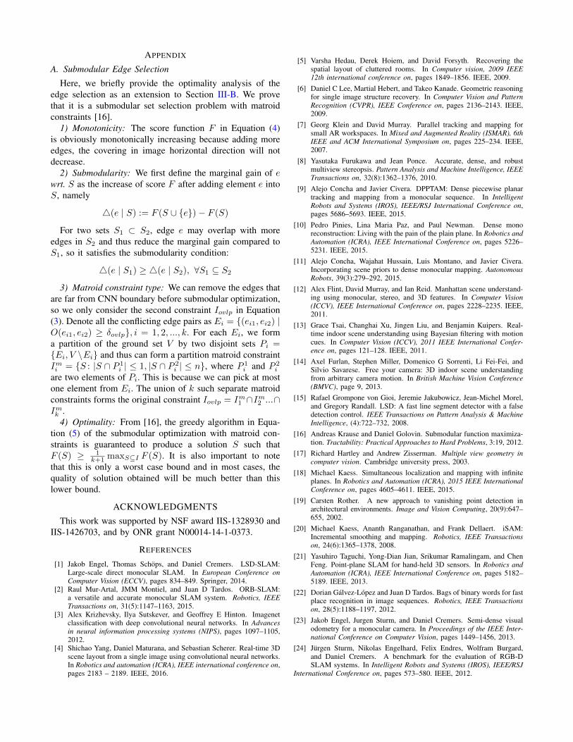
The result of our algorithms is shown in Figure 13 wherethe red line is Enhanced LSD SLAM and green line is LSDPop-up SLAM. With the automatic loop closure detection, theLSD Pop-up SLAM generates the best 3D map and smallestloop closure error. The grid dimension is 1× 1m2 in Figure13 and the loop closure positioning error is 0.4m of the total60m trajectory.
Fig. 12. Corridor dataset II with loop closure. (top) Sample frames in thedataset. (bottom): LSD SLAM result, ORB SLAM result.
C. Runtime Analysis
Finally, we provide the computation analysis of the Cor-ridor dataset II in Table II. All timings are measured onCPU (Intel i7, 4.0 GHz) and GPU (only for CNN). Mostof the code is implemented in C++. Currently, the CNNsegmentation, edge detection, and selection consumes 30ms.Note that compared to CNN model in [4], we change thefully connected layers from 4096 to 2048 to reduce thesegmentation time by half without affecting the accuracy toomuch. The iSAM incremental update takes 17.43ms whilebatch optimization takes 45.35ms. Therefore we only usebatch optimization to re-factor the information matrix whena loop closure is detected. In all, our plane SLAM algorithmcan run in real time at over 20Hz using single-threadedprogramming.
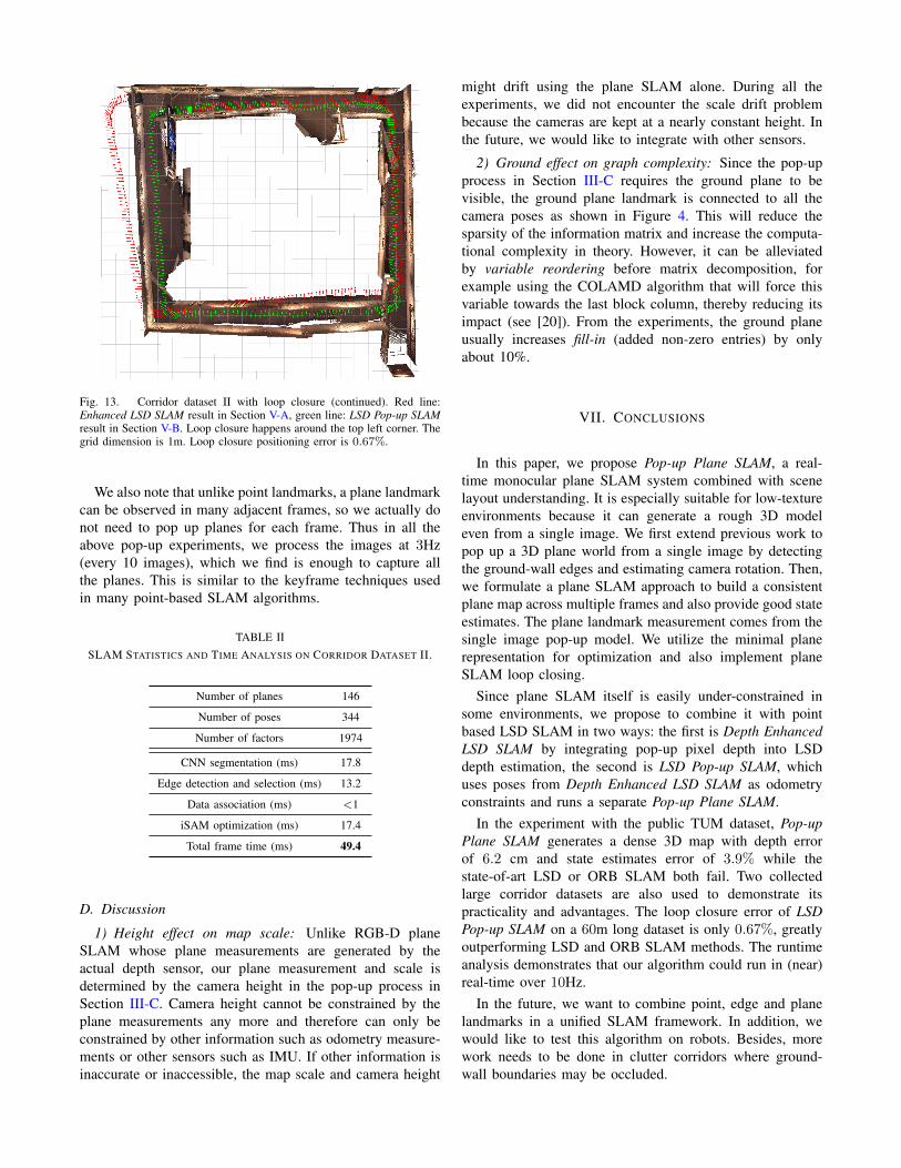
Fig. 13. Corridor dataset II with loop closure (continued). Red line:Enhanced LSD SLAM result in Section V-A, green line: LSD Pop-up SLAMresult in Section V-B. Loop closure happens around the top left corner. Thegrid dimension is 1m. Loop closure positioning error is 0.67%.
We also note that unlike point landmarks, a plane landmarkcan be observed in many adjacent frames, so we actually donot need to pop up planes for each frame. Thus in all theabove pop-up experiments, we process the images at 3Hz(every 10 images), which we find is enough to capture allthe planes. This is similar to the keyframe techniques usedin many point-based SLAM algorithms.
TABLE IISLAM STATISTICS AND TIME ANALYSIS ON CORRIDOR DATASET II.
Number of planes 146
Number of poses 344
Number of factors 1974
CNN segmentation (ms) 17.8
Edge detection and selection (ms) 13.2
Data association (ms) <1
iSAM optimization (ms) 17.4
Total frame time (ms) 49.4
D. Discussion
1) Height effect on map scale: Unlike RGB-D planeSLAM whose plane measurements are generated by theactual depth sensor, our plane measurement and scale isdetermined by the camera height in the pop-up process inSection III-C. Camera height cannot be constrained by theplane measurements any more and therefore can only beconstrained by other information such as odometry measure-ments or other sensors such as IMU. If other information isinaccurate or inaccessible, the map scale and camera height
might drift using the plane SLAM alone. During all theexperiments, we did not encounter the scale drift problembecause the cameras are kept at a nearly constant height. Inthe future, we would like to integrate with other sensors.
2) Ground effect on graph complexity: Since the pop-upprocess in Section III-C requires the ground plane to bevisible, the ground plane landmark is connected to all thecamera poses as shown in Figure 4. This will reduce thesparsity of the information matrix and increase the computa-tional complexity in theory. However, it can be alleviatedby variable reordering before matrix decomposition, forexample using the COLAMD algorithm that will force thisvariable towards the last block column, thereby reducing itsimpact (see [20]). From the experiments, the ground planeusually increases fill-in (added non-zero entries) by onlyabout 10%.
VII. CONCLUSIONS
In this paper, we propose Pop-up Plane SLAM, a real-time monocular plane SLAM system combined with scenelayout understanding. It is especially suitable for low-textureenvironments because it can generate a rough 3D modeleven from a single image. We first extend previous work topop up a 3D plane world from a single image by detectingthe ground-wall edges and estimating camera rotation. Then,we formulate a plane SLAM approach to build a consistentplane map across multiple frames and also provide good stateestimates. The plane landmark measurement comes from thesingle image pop-up model. We utilize the minimal planerepresentation for optimization and also implement planeSLAM loop closing.
Since plane SLAM itself is easily under-constrained insome environments, we propose to combine it with pointbased LSD SLAM in two ways: the first is Depth EnhancedLSD SLAM by integrating pop-up pixel depth into LSDdepth estimation, the second is LSD Pop-up SLAM, whichuses poses from Depth Enhanced LSD SLAM as odometryconstraints and runs a separate Pop-up Plane SLAM.
In the experiment with the public TUM dataset, Pop-upPlane SLAM generates a dense 3D map with depth errorof 6.2 cm and state estimates error of 3.9% while thestate-of-art LSD or ORB SLAM both fail. Two collectedlarge corridor datasets are also used to demonstrate itspracticality and advantages. The loop closure error of LSDPop-up SLAM on a 60m long dataset is only 0.67%, greatlyoutperforming LSD and ORB SLAM methods. The runtimeanalysis demonstrates that our algorithm could run in (near)real-time over 10Hz.
In the future, we want to combine point, edge and planelandmarks in a unified SLAM framework. In addition, wewould like to test this algorithm on robots. Besides, morework needs to be done in clutter corridors where ground-wall boundaries may be occluded.
APPENDIX
A. Submodular Edge Selection
Here, we briefly provide the optimality analysis of theedge selection as an extension to Section III-B. We provethat it is a submodular set selection problem with matroidconstraints [16].
1) Monotonicity: The score function F in Equation (4)is obviously monotonically increasing because adding moreedges, the covering in image horizontal direction will notdecrease.
2) Submodularity: We first define the marginal gain of ewrt. S as the increase of score F after adding element e intoS, namely
4(e | S) := F (S ∪ {e})− F (S)
For two sets S1 ⊂ S2, edge e may overlap with moreedges in S2 and thus reduce the marginal gain compared toS1, so it satisfies the submodularity condition:
4(e | S1) ≥ 4(e | S2), ∀S1 ⊆ S2
3) Matroid constraint type: We can remove the edges thatare far from CNN boundary before submodular optimization,so we only consider the second constraint Iovlp in Equation(3). Denote all the conflicting edge pairs as Ei = {(ei1, ei2) |O(ei1, ei2) ≥ δovlp}, i = 1, 2, ..., k. For each Ei, we forma partition of the ground set V by two disjoint sets Pi ={Ei, V \Ei} and thus can form a partition matroid constraintImi = {S : |S ∩ P 1
i | ≤ 1, |S ∩ P 2i | ≤ n}, where P 1
i and P 2i
are two elements of Pi. This is because we can pick at mostone element from Ei. The union of k such separate matroidconstraints forms the original constraint Iovlp = Im1 ∩Im2 ...∩Imk .
4) Optimality: From [16], the greedy algorithm in Equa-tion (5) of the submodular optimization with matroid con-straints is guaranteed to produce a solution S such thatF (S) ≥ 1
k+1 maxS⊆I F (S). It is also important to notethat this is only a worst case bound and in most cases, thequality of solution obtained will be much better than thislower bound.
ACKNOWLEDGMENTS
This work was supported by NSF award IIS-1328930 andIIS-1426703, and by ONR grant N00014-14-1-0373.
REFERENCES
[1] Jakob Engel, Thomas Schops, and Daniel Cremers. LSD-SLAM:Large-scale direct monocular SLAM. In European Conference onComputer Vision (ECCV), pages 834–849. Springer, 2014.
[2] Raul Mur-Artal, JMM Montiel, and Juan D Tardos. ORB-SLAM:a versatile and accurate monocular SLAM system. Robotics, IEEETransactions on, 31(5):1147–1163, 2015.
[3] Alex Krizhevsky, Ilya Sutskever, and Geoffrey E Hinton. Imagenetclassification with deep convolutional neural networks. In Advancesin neural information processing systems (NIPS), pages 1097–1105,2012.
[4] Shichao Yang, Daniel Maturana, and Sebastian Scherer. Real-time 3Dscene layout from a single image using convolutional neural networks.In Robotics and automation (ICRA), IEEE international conference on,pages 2183 – 2189. IEEE, 2016.
[5] Varsha Hedau, Derek Hoiem, and David Forsyth. Recovering thespatial layout of cluttered rooms. In Computer vision, 2009 IEEE12th international conference on, pages 1849–1856. IEEE, 2009.
[6] Daniel C Lee, Martial Hebert, and Takeo Kanade. Geometric reasoningfor single image structure recovery. In Computer Vision and PatternRecognition (CVPR), IEEE Conference on, pages 2136–2143. IEEE,2009.
[7] Georg Klein and David Murray. Parallel tracking and mapping forsmall AR workspaces. In Mixed and Augmented Reality (ISMAR), 6thIEEE and ACM International Symposium on, pages 225–234. IEEE,2007.
[8] Yasutaka Furukawa and Jean Ponce. Accurate, dense, and robustmultiview stereopsis. Pattern Analysis and Machine Intelligence, IEEETransactions on, 32(8):1362–1376, 2010.
[9] Alejo Concha and Javier Civera. DPPTAM: Dense piecewise planartracking and mapping from a monocular sequence. In IntelligentRobots and Systems (IROS), IEEE/RSJ International Conference on,pages 5686–5693. IEEE, 2015.
[10] Pedro Pinies, Lina Maria Paz, and Paul Newman. Dense monoreconstruction: Living with the pain of the plain plane. In Robotics andAutomation (ICRA), IEEE International Conference on, pages 5226–5231. IEEE, 2015.
[11] Alejo Concha, Wajahat Hussain, Luis Montano, and Javier Civera.Incorporating scene priors to dense monocular mapping. AutonomousRobots, 39(3):279–292, 2015.
[12] Alex Flint, David Murray, and Ian Reid. Manhattan scene understand-ing using monocular, stereo, and 3D features. In Computer Vision(ICCV), IEEE International Conference on, pages 2228–2235. IEEE,2011.
[13] Grace Tsai, Changhai Xu, Jingen Liu, and Benjamin Kuipers. Real-time indoor scene understanding using Bayesian filtering with motioncues. In Computer Vision (ICCV), 2011 IEEE International Confer-ence on, pages 121–128. IEEE, 2011.
[14] Axel Furlan, Stephen Miller, Domenico G Sorrenti, Li Fei-Fei, andSilvio Savarese. Free your camera: 3D indoor scene understandingfrom arbitrary camera motion. In British Machine Vision Conference(BMVC), page 9, 2013.
[15] Rafael Grompone von Gioi, Jeremie Jakubowicz, Jean-Michel Morel,and Gregory Randall. LSD: A fast line segment detector with a falsedetection control. IEEE Transactions on Pattern Analysis & MachineIntelligence, (4):722–732, 2008.
[16] Andreas Krause and Daniel Golovin. Submodular function maximiza-tion. Tractability: Practical Approaches to Hard Problems, 3:19, 2012.
[17] Richard Hartley and Andrew Zisserman. Multiple view geometry incomputer vision. Cambridge university press, 2003.
[18] Michael Kaess. Simultaneous localization and mapping with infiniteplanes. In Robotics and Automation (ICRA), 2015 IEEE InternationalConference on, pages 4605–4611. IEEE, 2015.
[19] Carsten Rother. A new approach to vanishing point detection inarchitectural environments. Image and Vision Computing, 20(9):647–655, 2002.
[20] Michael Kaess, Ananth Ranganathan, and Frank Dellaert. iSAM:Incremental smoothing and mapping. Robotics, IEEE Transactionson, 24(6):1365–1378, 2008.
[21] Yasuhiro Taguchi, Yong-Dian Jian, Srikumar Ramalingam, and ChenFeng. Point-plane SLAM for hand-held 3D sensors. In Robotics andAutomation (ICRA), IEEE International Conference on, pages 5182–5189. IEEE, 2013.
[22] Dorian Galvez-Lopez and Juan D Tardos. Bags of binary words for fastplace recognition in image sequences. Robotics, IEEE Transactionson, 28(5):1188–1197, 2012.
[23] Jakob Engel, Jurgen Sturm, and Daniel Cremers. Semi-dense visualodometry for a monocular camera. In Proceedings of the IEEE Inter-national Conference on Computer Vision, pages 1449–1456, 2013.
[24] Jurgen Sturm, Nikolas Engelhard, Felix Endres, Wolfram Burgard,and Daniel Cremers. A benchmark for the evaluation of RGB-DSLAM systems. In Intelligent Robots and Systems (IROS), IEEE/RSJ
International Conference on, pages 573–580. IEEE, 2012.
![EGO-SLAM: A Robust Monocular SLAM for …arXiv:1707.05564v2 [cs.CV] 17 Nov 2018 In this paper, we investigate the monocular SLAM prob-lem with a special emphasis on EGOcentric videos,](https://img.pdfslide.us/doc/110x75/5fe2bff5b533fd76167f3e75/ego-slam-a-robust-monocular-slam-for-arxiv170705564v2-cscv-17-nov-2018-in.jpg)


![EGO-SLAM: A Robust Monocular SLAM for Egocentric Videossuvam/rslam_wacv19_camera_ready.pdf · Figure 1: Incremental nature of state of the art SLAM [32,9,19] as well as SFM [56,55,50]](https://img.pdfslide.us/doc/110x75/601f57958b217666bc405b71/ego-slam-a-robust-monocular-slam-for-egocentric-suvamrslamwacv19camerareadypdf.jpg)