Embed Size (px)
Citation preview
Pool Boiling of Novec 7300 and Self-Rewetting Fluids on
Electrically-Assisted Supersonically Solution-Blown, Copper-Plated
Nanofibers
Rakesh P. Sahu1, Sumit Sinha-Ray
1, Suman Sinha-Ray
1,2,3, Alexander L. Yarin
1,4*
1Department of Mechanical and Industrial Engineering,
University of Illinois at Chicago,
842 W. Taylor St., Chicago IL 60607-7022, USA
2Corporate Innovation Center, United States Gypsum, Libertyville, IL-60048, USA
3 Department of Materials Science and Engineering, Indian Institute of Technology, Indore,
Madhya Pradesh 452017, India
4College of Engineering, Korea University, Seoul 136-713, Republic of Korea
Abstract
Pool boiling of Novec 7300 fluid and self-rewetting water-heptanol mixtures on bare
copper surface and a copper surface coated with copper-plated nanofibers is studied
experimentally. The experimental data revealed a significant increase in the heat removal rate up
to the critical heat flux (CHF) on the copper-plated nanofiber surfaces in comparison with bare
copper surfaces. Also, the critical heat flux increases on the copper-plated nanofiber surface,
albeit it is reached at a lower surface superheat in comparison with bare copper surface. Prolong
boiling in water facilitates oxidation of the layer of copper-plated nanofibers, and diminishes its
roughness, albeit does not affect the heat transfer rate.

2
* To whom correspondence should be addressed. E-mail: [email protected]. Phone: (312) 996-
3472. Fax: (312) 413-0447.
Keywords: Nano-textured surfaces; Copper-plated nanofibers; Pool boiling enhancement;
Supersonic solution blowing.
1. Introduction
In the year 1965 Gordon E. Moore in his seminal paper1 had predicted that the number of
transistors in a dense integrated circuit to be used for computing will double up almost every two
years and that prediction is still holding true to keep up with the pace of computing, automation
and boom in datacom industry. This resulted in an exponential increase in the number of
computations per input power (MegaFlops per watt), as high as from 20 MFlops/watt in the year
of 2004 to 600 MFlops/watt in 2010 [2]. Miniaturization of transistors posed an acute problem in
heat dissipation and effective heat removal from microelectronic equipment became one of the
biggest challenges. Several cooling technologies such as single-phase liquid cooling, flow
boiling, jet impingement cooling, spray cooling, heat pipes, thermosyphons, and pool boiling
with their advantages and drawbacks are used. Broadly speaking, cooling technologies can be
subdivided into direct liquid cooling and indirect liquid cooling using both single- and two-phase
media. Pool boiling is considered as one of the most promising remedies for the thermal
management problem. It is used not only for thermal management and cooling of microelectronic
devices, but also in nuclear power plants, air conditioners, refrigerators, for fluid handling and
control, orbit storage and supply systems for cryogenic propellants and life support fluids.
Pool boiling regimes are dictated by the surface temperature and the heat flux and include
consequently natural convective boiling, nucleate boiling, transitional boiling and film boiling. In

3
the nucleate boiling regime the heat flux from the surface increases with the wall temperature
until it reaches the maximum heat flux called the critical heat flux (CHF). After the CHF, a vapor
layer forms over the heater surface and the heat flux decreases as the surface temperature
significantly increases. The challenge is to increase the heat flux at low wall temperature and
several different mechanisms could be employed to achieve this. A thorough understanding of
the boiling heat transfer and CHF is essential for developing the next generation of heat removal
techniques.
Pool boiling of various coolants such as water, alcohol, Novec fluids, fluorinert fluids and
refrigerants on different surfaces (wires or plane surfaces of different roughness) has been
studied [3-8]. Several empirical and semi-empirical models were proposed to describe pool
boiling under Earth gravity conditions [9-14]. Small concentrations of nanoparticles such as
alumina, zirconia or silica in the boiling liquids were found to be an efficient way to enhance the
CHF [15-18]. Nucleation rate, growth and departure of vapor bubbles are enhanced on
superhydrophobic surfaces and thus heat removal is enhanced at lower degree of superheat [19-
22]. Fluorinated compounds such as FC 72, FC 77, Novec 7100, Novec 7200, and Novec 7300
are of potential interest for microelectronics cooling due to the unique combination of low
dielectric constant and high thermal and chemical stability. In addition to that, owing to their
chemical inertness, unlike other fluids, FC fluids pose no harm for the microelectronics
characteristics. Pool boiling of several fluorinerts, Novec fluids and other dielectric fluids have
been reported earlier on different surfaces and in several mixtures [23-26]. As these fluorinerts
and Novec fluids are used in direct liquid cooling of the electronic components, pool boiling
study of these fluids is essential.
4
The influence of the electric field on bubble departure, bubble diameter and thus the heat
flux was studied under various gravity conditions. It was found to be a reliable mechanism for
bubble detachment and heater surface re-wetting in microgravity [27, 28].
Concentration-driven Marangoni effect and the thermocapillarity oppose liquid flow in a
thin layer between the bubble and the heater surface for most pure liquids and binary mixtures.
Dilute aqueous solutions of high carbon alcohols (number of carbon atoms ≥ 4) also called self-
rewetting fluids, used in indirect liquid cooling of electronic components reveal an increase in
surface tension with temperature after a certain point. This allows both the concentration-driven
Marangoni effect and thermocapillarity to pull liquid in the same direction and drive the flow
towards the heated surface, thus removing the bubbles. Pool boiling of self-rewetting fluids
showed an enhancement of cooling performance and prevented the dry-out phenomenon [29-31].
Nano-textured surfaces formed by metal-plated nanofibers revealed attractive features for
such applications as spray cooling and pool boiling [32-36]. The dramatic increase in the bubble
nucleation rate and projected area density on metal-plated nanofiber mats is due to the increased
temperature of the liquid entrapped in the fluffy surface provided by nanofiber mats. Moreover,
the nano-textured surfaces provide numerous nucleation points for the bubble nucleation and
growth. An increased nucleation rate due to the multiple nucleation sites on nano-textured
surfaces, results in the enhanced bubble formation. This causes an increased mixing within the
bulk fluid, and thus contributes to higher heat transfer rate. In addition, the increased surface area
of the nano-textured surfaces provides a greater heat flux according to the Newton’s law of
cooling. The increased surface area associated with metal-plated nanofiber mats located at the
heater surface is also beneficial for the enhanced cooling by impinging jets of air [37]. Overall,

5
inexpensive nano-textured surfaces hold great potential of solving an acute thermal management
problem, which surmount to billions of dollars [38, 39].
In the present work pool boiling of Novec 7300 and water-heptanol (0.1% by vol.) mixture
is studied on both bare copper surface and copper-plated nanofiber surface. Section 2 describes
preparation of nano-textured surface. Pool boiling experiments are detailed in section 3. The
experimental results are discussed in section 4 and conclusions are drawn in section 5.
2. Preparation of Nanofiber Mats on Heater Surface
2.1. Materials
Polymer polyacrylonitrile (PAN; molecular weight Mw=150 kDa) was obtained from
Polymer Inc. Solvent N,N-Dimethyl formamide (DMF) anhydrous-99.8%, and compounds used
for copper-plating (sulfuric acid, hydrochloric acid, copper sulfate-pentahydrate, and
formaldehyde), as well as the working fluid n-heptanol were obtained from Sigma-Aldrich.
Novec 7300 fluid was purchased from 3M. Oxygen-free high-conductive (OFHC) 101 grade
copper plates and rods were purchased from Mcmaster-Carr to use as anode for copper-plating.
They were cut into cylindrical pieces and used as substrates. Prior to deposition of nanofiber
mats, copper plates were roughened using a 3M Pro Grade sand paper P600.
2.2. Electrically-Assisted Supersonic Solution Blowing and Electroplating
Electrically-assisted supersonic solution blowing was conducted with 6 wt% PAN solutions
in DMF as in the previous work of this group [36]. Cu substrates used in the experiments, were
employed as nanofiber collectors. Polymer nanofibers were deposited on them directly for 10

6
min. The obtained polymer nanofiber mats were then copper-plated to enhance their thermal
conductivity. For copper-plating a nanofiber mat was first sputter coated with 7.5 nm Pt-Pd layer
using Cressington Sputter Coater to establish electrical path between Cu ions and insulating
polymer nanofibers. At the following stage such sputter-coated layer acted as a conductive
“mask” for the nanofibers for successful copper plating. The electroplating bath was filled with a
mixture of sulfuric acid (5 g), hydrochloric acid (0.5 g), copper sulfate-pentahydrate (16 g) and
formaldehyde (10 g) in 100 mL of deionized (DI) water. Electroplating was conducted using the
Electroplating Station HSEPS-10 following the procedure as described in Ref. 36.
2.3. Characterizations
Scanning electron microscopy (SEM) of copper-plated nanofiber mats was done using
JEOL JSM-6320F with a cold emission source, while the optical images were taken using optical
microscope Olympus BX-51. The surface roughness of both bare copper and nanofiber-coated
copper surface was analyzed with the Bruker 3D Optical Microscope GTK1. The high-speed
imaging was done using a Phantom V210 camera, and Nikon D3100 camera was used to record
long-time videos illustrating the CHF patterns. The X-ray Diffraction analysis of the copper-
plated nanofiber surface was conducted using Siemens X-ray machine.
3. Pool Boiling Experiments
3.1 Experimental Setup
The experimental setup used in the present work was based on our previous design [36]
with many modifications. The main parts of the experimental setup are the primary Teflon
casing, the secondary Teflon casing, the main copper rod, the copper substrate, the glass
chamber, the recuperating unit, the back cover and the cartridge heater assembly. The schematic
of the experimental setup is shown in Fig. 1. The primary copper rod of length 3” was machined
7
into three step-sections of different diameters of 0.75”, 1.75” and 1.5”, respectively. The
reduction of cross-section of the primary copper rod was done to intensify the heat flux at the
surface. The primary copper rod was bolted to the primary Teflon casing. An air gap of radius
0.125” was allowed to insulate the copper rod with the primary Teflon casing to avoid the
conduction losses. Five 200W cartridge heaters, purchased from Omega (3/8" x 1.50") were used
as heat source and were placed inside the holes drilled in the copper rod. Springs were placed on
the rear side of each cartridge heater and were then pressed with the back Teflon cover. This
ensured a proper contact of the heater with the copper rod surface minimizing heat losses
through the system.
The copper substrate was a cylindrical piece of diameter 0.75” and height 0.75”, where
0.25” of its height was threaded to a diameter of 0.25”. The copper substrate was screwed into
the copper rod. A thin layer of thermally-conductive silver paste was applied in-between the
copper substrate and the copper rod to eliminate any air gap and facilitate proper heat transfer
across the interface. Two holes were drilled within the copper substrate at a distance of 6.25 mm
between them. The holes were drilled to the center of the copper substrate.
The secondary Teflon casing was attached to the glass chamber, the outer casing of
which was made from aluminum. The boiling chamber was a parallelepiped of size 1.5”x1.5”x
3.25” and was made of glass. The secondary Teflon casing with the boiling chamber was then
placed on the copper substrate. An O-ring was used to seal the gap between the copper substrate
and the secondary Teflon casing. The vapor recuperating unit was then placed on top of the
boiling chamber. Cold water flowing through the recuperating unit kept the temperature of the
unit well below the room temperature and allowed the vapor formed inside the chamber to
condense within it. A small hole of 1 mm was drilled at the top of the vapor recuperating unit
8
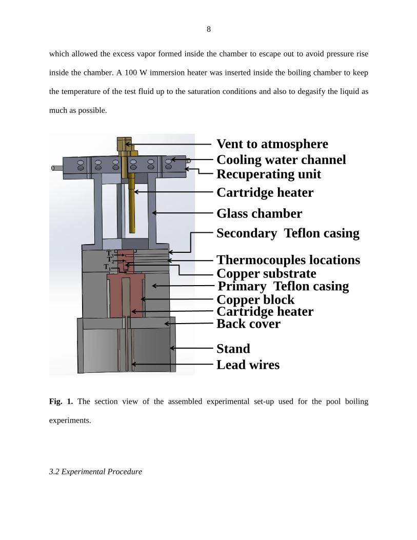
which allowed the excess vapor formed inside the chamber to escape out to avoid pressure rise
inside the chamber. A 100 W immersion heater was inserted inside the boiling chamber to keep
the temperature of the test fluid up to the saturation conditions and also to degasify the liquid as
much as possible.
Fig. 1. The section view of the assembled experimental set-up used for the pool boiling
experiments.
3.2 Experimental Procedure
Copper block
Recuperating unit
Secondary Teflon casing
Thermocouples locations
Cartridge heater
Cartridge heater
Cooling water channel
Glass chamber
Vent to atmosphere
Back cover
Copper substrate
Stand
Lead wires
Primary Teflon casing
T3T2
T1

9
The copper substrates, either a bare one or the one coated with copper-plated nanofibers,
was placed over the primary copper rod. The T-type thermocouples were then inserted into the
copper substrate and connected to the HH806AW microprocessor thermometer purchased from
Omega. The thermocouples were covered with conductive silver paste to ensure good thermal
contact with the copper substrate. The five cartridge heaters inside the primary copper rod were
all connected in parallel and powered using a variable autotransformer. The variable
autotransformer provided variable voltage and current output at varied percentage setting. The
voltage and current at different percentage settings of the autotransformer were recorded using
Fluke 115 true RMS multimeter. Test liquid (90 ml) was poured into the boiling chamber in each
experiment. The variable transformer was turned on at 16% setting along with the immersion
heater being on too. They were kept at this setting for 50 min. This procedure was used to
degasify the liquid inside the chamber. Then the input of the variable transformer was increased
with an interval of 4%. After 10 min of changing the percentage setting, the thermocouple
reading did not show any variation indicating that the system had reached a steady state. The
temperature values at the thermocouple locations were then recorded.
4. Results and Discussion
4.1. Pool Boiling of Novec 7300
The pool boiling experiments with Novec 7300 fluid were conducted using both bare
copper surfaces and copper surfaces coated with copper-plated nanofibers. The working fluid (90
ml) was located in the boiling chamber with both the immersion heater and the variable
autotransformer (16%) kept on for 50 min. This partially degasifies the fluid without any
nucleation from the surface of the copper substrate. The autotransformer setting was then
10
increased with an interval of 4% and kept at that setting for the next 10 min. This is the
maximum time it takes the system to reach steady state. The voltage, current and the
thermocouple readings were taken at each setting after the system had reached steady state. The
power input to the cartridge heaters P which was transferred to the copper rod was calculated as
P=VI, where V is the voltage applied across each identical cartridge heater and I is the total
current through all the heaters.
The temperature gradient across the thermocouples at locations T2 and T3 (cf. Fig. 1) was
used to obtain the surface temperature of the copper substrate Ts using the following expression
2 3s 3 3s
23
T -TT = T - Δx
Δx
(1)
where 23x is the distance between the thermocouple locations T2 and T3 and 3sΔx is the
distance between the thermocouple location T3 (cf. Fig. 1) and the surface. The degree of
superheat ΔT was obtained as the difference of the surface temperature Ts and the saturation
temperature of the boiling liquid Tw. The heat transfer to the boiling liquid from the surface of
the copper substrate is then found using the Fourier law as
" 3 2cu
23
T - Tq = -k
Δx (2)
where cuk = 401 W/ m K is the thermal conductivity of copper.
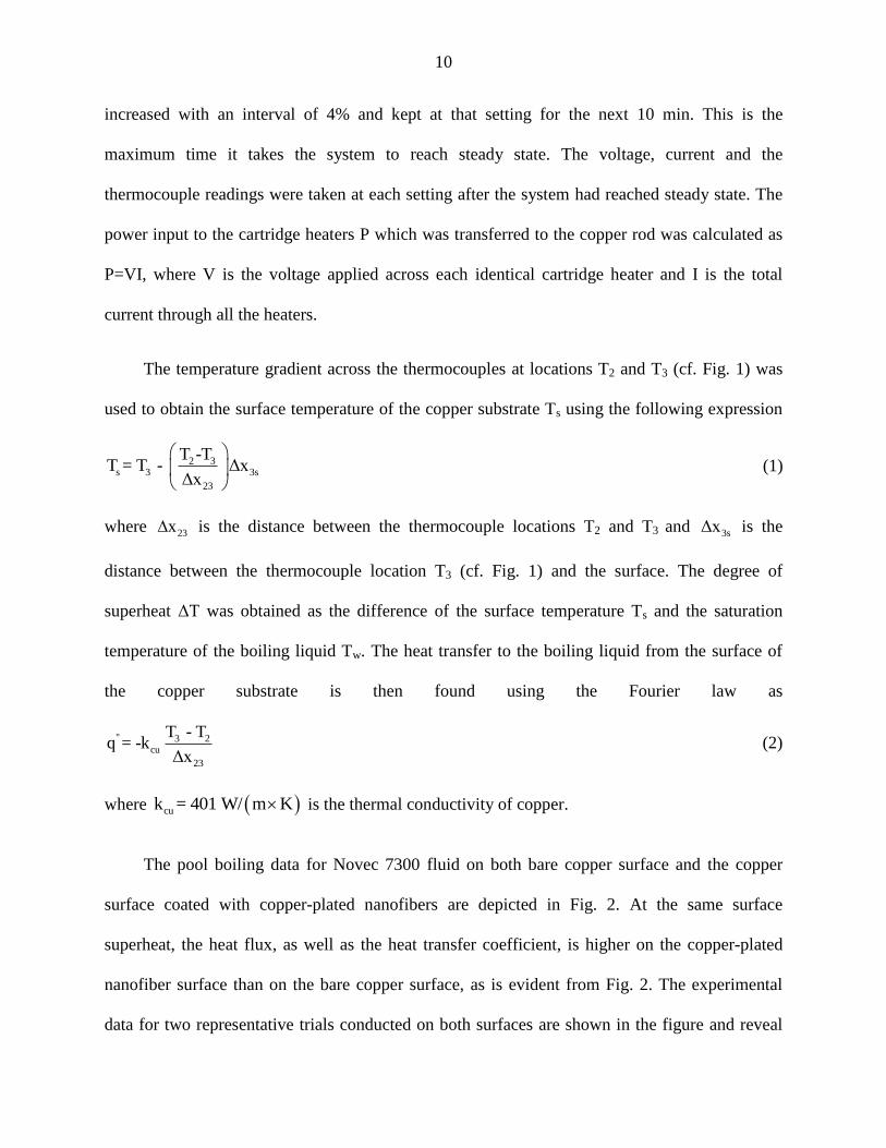
The pool boiling data for Novec 7300 fluid on both bare copper surface and the copper
surface coated with copper-plated nanofibers are depicted in Fig. 2. At the same surface
superheat, the heat flux, as well as the heat transfer coefficient, is higher on the copper-plated
nanofiber surface than on the bare copper surface, as is evident from Fig. 2. The experimental
data for two representative trials conducted on both surfaces are shown in the figure and reveal
11
good repeatability. In the case of the copper-plated nanofiber surface, nucleation begins at a very
low superheat in comparison to the bare copper surface. The temperature at which nucleation
begins is reduced by 6 °C on copper-plated nanofibers. The heat transfer coefficient h was
calculated as h q"/ T . The robustness of the samples and repeatability of the results on each
of them was additionally verified by conducting several trials on the same copper-plated
nanofiber surface. No decay in the heat removal rate was observed due to aging of the nano-
textured surfaces. Figure 3 shows the optical microscope and SEM images both before and after
pool boiling experiments. The actual copper sample used in the experiment is too big to be
observed in SEM. To observe the effect of pool boiling on the nanofibers a smaller copper disc
was used for depositing the nanofibers and subsequently copper plating them under the
conditions identical to the actual samples. The smaller copper disc was then used in pool boiling
experiments with the setup described in [35]. No visual delamination was observed during such
pool boiling experiments indicating the robustness of the nano-textured surface. This, ensures
that the surface does not deteriorate after repeated pool boiling experiments on it which last for
several hours. The robustness of the samples is also corroborated by the repeatability of the
results of the actual pool boiling experiments in the present work (e.g. in Fig. 2).
12
Fig. 2. Pool boiling data for Novec 7300 fluid on bare copper surface and copper surface coated
with a thin (15-20 µm) layer of copper-plated nanofibers. The experiments have been repeated
twice on the same surface and the results for trials 1 and 2 are shown by the corresponding filled
and open symbols. (a) Heat flux versus surface superheat, and (b) the corresponding heat transfer
coefficient versus surface superheat. Notation: Bare corresponds to bare copper surface, NT-to
nano-textured surface of copper-plated nanofibers.
The remarkable steepness of the boiling curve measured on the nano-textured surfaces (cf.
Fig. 2a) reveals a sharp rise of the heat removal rate at very low surface superheat. It was
possible to reach the critical heat flux (CHF) with the present setup and it increased by 33% on
the copper- plated nanofiber surface compared to the bare copper surface. Moreover, the CHF on
the copper- plated nanofiber surface was reached at a lower (by 10 °C) surface superheat than on
the bare copper surface. A similar result (the CHF reached at a surface superheat lowered by 5.3
°C) was reported in [25] for pool boiling of Novec 7300 fluid on sintered copper surfaces with
carbon nanotubes. Pool boiling is an efficient cooling technique in a wide range of the degree of
(b)(a)

13
superheat. Most of the electronic devices operate at variable percentage of their maximum capacity and
thus produce various heat fluxes. In the case of cooling of high-power microelectronics one of the
objectives is to remove high heat flux even at a relatively low degree of superheat. Early boiling from a
nano-textured surface at lower degree of superheat facilitates enhanced cooling as the phase change heat
transfer is higher than the conductive and convective heat transfer characteristic of lower degrees of
superheat.
Fig. 3. Optical microscope image (a-b) and SEM image (c-d) of copper plated nano-textured
surface on copper substrate both before (a, c) and after (b, d) pool boiling experiments in the
setup of [35]. Scale bars are 10 µm in panels (a, b) and 1 µm in panels (c, d). No deterioration of
the nanofibers had been observed after the pool boiling experiments.
(a) (b)
(c) (d)

14
At CHF a vapor film forms over the heater surface which acts as an insulating layer
between the bulk fluid and the heater, as a result of which the temperature at the thermocouple
locations T2 and T3 keep rising continuously. Both the cartridge heaters and the immersion heater
were kept on and the temperatures of the thermocouples were monitored and recorded until the
temperature at the location T2 had reached 210 °C, a safety limit for the Teflon casing in this
setup. The heat flux measurements were conducted using the temperature gradient even after the
CHF had been reached. The heat flux beyond CHF decreases slowly in case of copper-plated
nanofiber as is evident from the slope of the pool boiling curve after the CHF had been reached
(cf Fig. 2a). The boiling curve after CHF is steeper on the bare copper surface than on the
copper-plated nanofiber surface, which is similar to the observations in [35]. This is due to the
fact that as the CHF has been reached and a vapor film formed over the copper surface, the
roughness of the copper-plated nanofiber surface facilitated film destabilization and break-up
into separate bubbles. The high-speed videos of the pool boiling at the CHF and beyond were
recorded using Phantom V210 camera on both types of surfaces (cf. the Supporting videos S1
and S2). It can be seen from the video how the intact vapor film is destroyed locally and then
followed by spreading of nucleate boiling over the entire heated surface, either a bare copper or a
copper surface coated with copper-plated nanofibers. The pool boiling of Novec 7300 fluid at the
CHF and beyond was also recorded using a DSLR camera on both types of surfaces at 33 fps (cf.
the Supporting videos S3 and S4). Figure 4 shows how the thick vapor film is destabilized after
the CHF has been reached and the heaters turned off at the temperature T1 =210 °C. It is seen
how the vapor film subsequently breaks up into trains of small individual bubbles. The
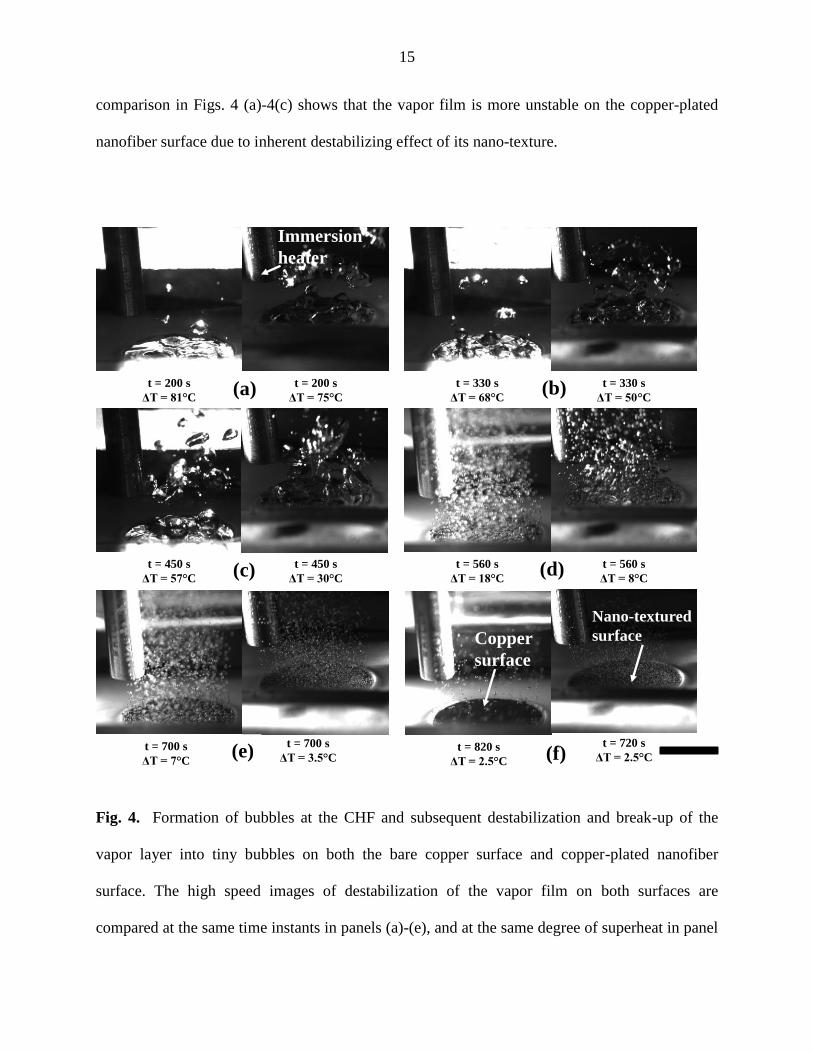
15
comparison in Figs. 4 (a)-4(c) shows that the vapor film is more unstable on the copper-plated
nanofiber surface due to inherent destabilizing effect of its nano-texture.
Fig. 4. Formation of bubbles at the CHF and subsequent destabilization and break-up of the
vapor layer into tiny bubbles on both the bare copper surface and copper-plated nanofiber
surface. The high speed images of destabilization of the vapor film on both surfaces are
compared at the same time instants in panels (a)-(e), and at the same degree of superheat in panel
t = 200 s
ΔT = 81 C
t = 200 s
ΔT = 75 C
t = 330 s
ΔT = 68 C
t = 330 s
ΔT = 50 C
t = 450 s
ΔT = 57 C
t = 450 s
ΔT = 30 C
t = 560 s
ΔT = 18 C
t = 560 s
ΔT = 8 C
t = 700 s
ΔT = 7 C
t = 700 s
ΔT = 3.5 Ct = 820 s
ΔT = 2.5 C
t = 720 s
ΔT = 2.5 C
Immersion
heater
(a) (b)
(c) (d)
(e) (f)
Nano-textured
surfaceCopper
surface

16
(f). Each panel contains two images: the left one corresponds to the bare copper surface, and the
right one - to the copper-plated nanofiber surface. The time t = 0 corresponds to the moment
when the cartridge heaters and the immersion heater were turned off. Scale bar is 1cm.
The images shown in each panel in Fig. 4 were shot at the same time instant, and the
surface superheat was found to be less at the nano-textured surface than at the bare copper
surface. When the entire vapor film is destabilized due to the Rayleigh-Taylor instability (with
the denser liquid being supported by a lighter vapor layer with the gravity acceleration being
directed toward the lighter layer), isolated vapor columns are formed and break up into trains of
individual bubbles (due to the Rayleigh capillary instability) [40], which subsequently decrease
in size. As the heater was turned off, these vapor bubble trains facilitate surface cooling and thus
reduce the wall superheat. The size of the bubbles is smaller and their area density on the nano-
textured surface is higher than those on the bare copper surface which is evident from Fig. 4 (d-
f), especially in the case of ∆T=2.5 oC.
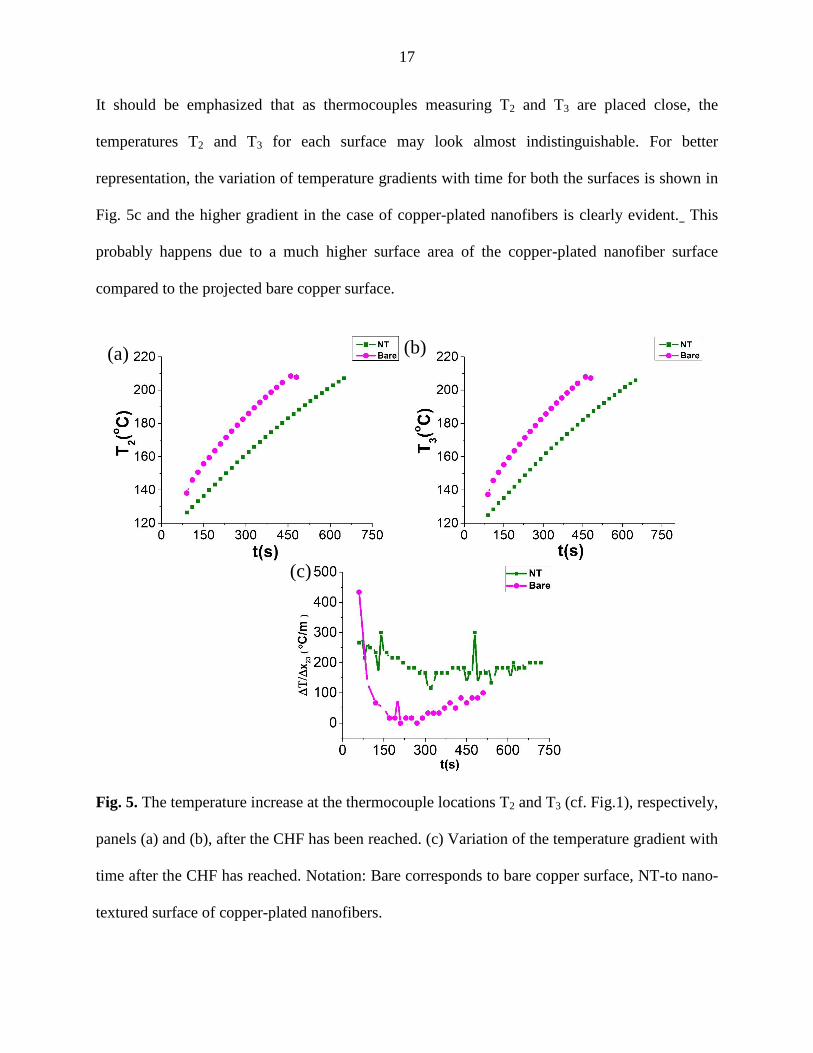
The temperature rise at the thermocouple locations T2 and T3 was recorded every 10 s
after the CHF was reached for both the bare copper surface and copper-plated nanofiber surface,
with the results being shown in Fig. 5. The objective in this case was to see how the temperature
of the sample rises even after the CHF is reached. Both the immersion heater and the cartridge
heaters were kept on. The temperature rise is steeper and the cut-off limit for the temperature is
reached much earlier in the case of the bare copper surface than for the copper-plated nanofiber
surface. This suggests that the nanofiber surface delays the temperature rise or in other words
allows higher heat removal rate across the vapor film formed on the surface even after the CHF.
17
It should be emphasized that as thermocouples measuring T2 and T3 are placed close, the
temperatures T2 and T3 for each surface may look almost indistinguishable. For better
representation, the variation of temperature gradients with time for both the surfaces is shown in
Fig. 5c and the higher gradient in the case of copper-plated nanofibers is clearly evident. This
probably happens due to a much higher surface area of the copper-plated nanofiber surface
compared to the projected bare copper surface.
Fig. 5. The temperature increase at the thermocouple locations T2 and T3 (cf. Fig.1), respectively,
panels (a) and (b), after the CHF has been reached. (c) Variation of the temperature gradient with
time after the CHF has reached. Notation: Bare corresponds to bare copper surface, NT-to nano-
textured surface of copper-plated nanofibers.
(a) (b)
(c)
18
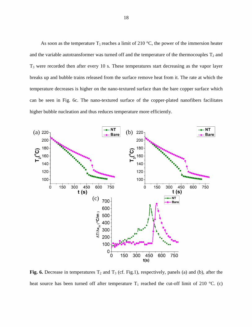
As soon as the temperature T1 reaches a limit of 210 °C, the power of the immersion heater
and the variable autotransformer was turned off and the temperature of the thermocouples T2 and
T3 were recorded then after every 10 s. These temperatures start decreasing as the vapor layer
breaks up and bubble trains released from the surface remove heat from it. The rate at which the
temperature decreases is higher on the nano-textured surface than the bare copper surface which
can be seen in Fig. 6c. The nano-textured surface of the copper-plated nanofibers facilitates
higher bubble nucleation and thus reduces temperature more efficiently.
Fig. 6. Decrease in temperatures T2 and T3 (cf. Fig.1), respectively, panels (a) and (b), after the
heat source has been turned off after temperature T1 reached the cut-off limit of 210 °C. (c)
(a) (b)
(c)

19
Variation of the temperature gradient with time after the CHF has reached. Notation: Bare
corresponds to bare copper surface, NT-to nano-textured surface of copper-plated nanofibers.
4.2. Pool Boiling of Water-Heptanol Mixture
Pool boiling of pure water and water-heptanol mixture (0.1% by vol, which is the
maximum solubility of heptanol in water) was conducted following the approach described in the
previous section. Several trials were done on many surfaces and two of them are shown in the
figures in the present section as the representative cases. The pool boiling data for pure water is
shown in Fig. 7. At the same degree of superheat, the heat flux and the heat transfer coefficient
on the copper-plated nanofiber surface was higher than those on the bare copper surface. The
inception of bubble nucleation from the nano-textured surface was found at the surface superheat
of 1.5 °C.
Fig. 7. Pool boiling data of water on bare copper surface and copper-plate nanofiber layer. The
experiments have been repeated twice on the same surface and the results for trials 1 and 2 are
shown by the corresponding filled and open symbols. (a) Heat flux versus surface superheat, and
(a) (b)

20
(b) the corresponding heat transfer coefficient versus surface superheat. Notation: Bare
corresponds to bare copper surface, NT-to nano-textured surface of copper-plated nanofibers.
The pool boiling experiments with water and water-heptanol mixture were not allowed
reaching the CHF due to the safety concerns related to the construction of the experimental
setup. Therefore, the transformer setting was limited to 60% of its maximum rating. The surface
superheat at which the maximum heat flux on the nano-textured surface was reached was by 4.5
°C lower than on the bare copper surface. At any surface superheat the heat flux on the copper-
plated nanofiber surface was 2-3 times higher than that on the bare copper surface. The pool
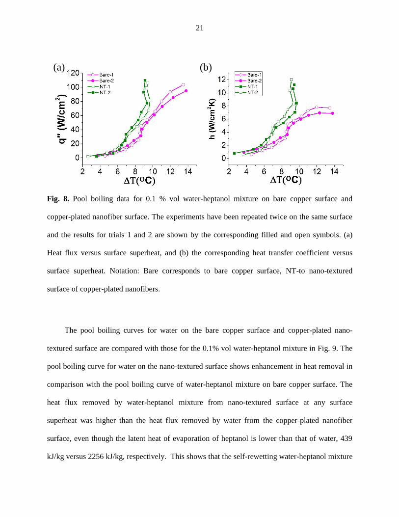
boiling data for water-heptanol mixture is depicted in Fig. 8. The heat flux and the heat transfer
coefficient were higher on the copper-plated nanofiber surface than those on the bare copper
surface. The surface superheat at which the vapor bubble nucleation was observed from the
nano-textured surface was by 2 °C lower than that for the bare copper surface. The surface
superheat at which the maximum heat flux was reached on the nano-textured surface was by 4.5
°C lower than that on the bare copper surface.
21
Fig. 8. Pool boiling data for 0.1 % vol water-heptanol mixture on bare copper surface and
copper-plated nanofiber surface. The experiments have been repeated twice on the same surface
and the results for trials 1 and 2 are shown by the corresponding filled and open symbols. (a)
Heat flux versus surface superheat, and (b) the corresponding heat transfer coefficient versus
surface superheat. Notation: Bare corresponds to bare copper surface, NT-to nano-textured
surface of copper-plated nanofibers.
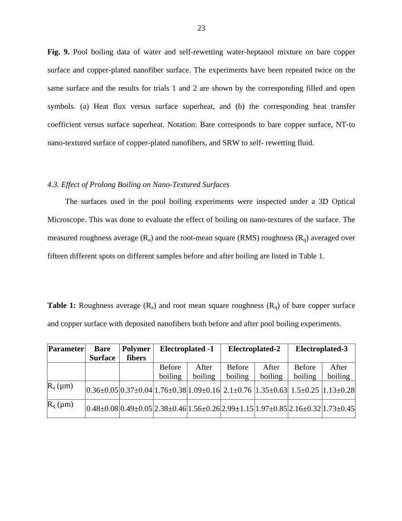
The pool boiling curves for water on the bare copper surface and copper-plated nano-
textured surface are compared with those for the 0.1% vol water-heptanol mixture in Fig. 9. The
pool boiling curve for water on the nano-textured surface shows enhancement in heat removal in
comparison with the pool boiling curve of water-heptanol mixture on bare copper surface. The
heat flux removed by water-heptanol mixture from nano-textured surface at any surface
superheat was higher than the heat flux removed by water from the copper-plated nanofiber
surface, even though the latent heat of evaporation of heptanol is lower than that of water, 439
kJ/kg versus 2256 kJ/kg, respectively. This shows that the self-rewetting water-heptanol mixture
(a) (b)

22
[29] results in a higher heat removal rate from nano-textured surface than pure water. This is
attributed to a higher bubble removal rate and thus higher heat flux. In this case both the
thermocapillary and concentrational Marangoni flow (the latter is due to faster evaporation of
heptanol than water) act in the same direction, which assists to vapor bubble removal in self-
rewetting fluids (one of them is the present water-heptanol mixture). It should be emphasized
that the self-rewetting liquid promotes early removal of bubbles as both the thermocapillary and
the concentrational Marangoni flow deliver the liquid toward the bubble interface and the heater
surface, to which the bubble is attached. As soon as a bubble detaches from the surface, the site
is again available for the nucleation and growth of a new bubble. In other words, the early bubble
removal facilitates the nucleation and growth of the next “generation” of bubbles. Overall, the
number of bubbles, which have nucleated and detached per unit time is higher in the case of self-
rewetting liquid. Thus, the self-rewetting liquid promotes bubble formation by removing them
quickly from the surface and thus yielding a higher heat flux.
(a) (b)
23
Fig. 9. Pool boiling data of water and self-rewetting water-heptanol mixture on bare copper
surface and copper-plated nanofiber surface. The experiments have been repeated twice on the
same surface and the results for trials 1 and 2 are shown by the corresponding filled and open
symbols. (a) Heat flux versus surface superheat, and (b) the corresponding heat transfer
coefficient versus surface superheat. Notation: Bare corresponds to bare copper surface, NT-to
nano-textured surface of copper-plated nanofibers, and SRW to self- rewetting fluid.
4.3. Effect of Prolong Boiling on Nano-Textured Surfaces
The surfaces used in the pool boiling experiments were inspected under a 3D Optical
Microscope. This was done to evaluate the effect of boiling on nano-textures of the surface. The
measured roughness average (Ra) and the root-mean square (RMS) roughness (Rq) averaged over
fifteen different spots on different samples before and after boiling are listed in Table 1.
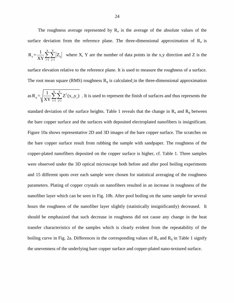
Table 1: Roughness average (Ra) and root mean square roughness (Rq) of bare copper surface
and copper surface with deposited nanofibers both before and after pool boiling experiments.
Parameter Bare
Surface
Polymer
fibers
Electroplated -1 Electroplated-2 Electroplated-3
Before
boiling
After
boiling
Before
boiling
After
boiling
Before
boiling
After
boiling
Ra (µm) 0.36±0.05 0.37±0.04 1.76±0.38 1.09±0.16 2.1±0.76 1.35±0.63 1.5±0.25 1.13±0.28
Rq (µm) 0.48±0.08 0.49±0.05 2.38±0.46 1.56±0.26 2.99±1.15 1.97±0.85 2.16±0.32 1.73±0.45
24
The roughness average represented by Ra is the average of the absolute values of the
surface deviation from the reference plane. The three-dimensional approximation of Ra is
X Y
a ij
i=1 j=1
1R = Z
XY where X, Y are the number of data points in the x,y direction and Z is the
surface elevation relative to the reference plane. It is used to measure the roughness of a surface.
The root mean square (RMS) roughness Rq is calculated in the three-dimensional approximation
asX Y
2
q i j
i=1 j=1
1R = Z (x ,y )
XY . It is used to represent the finish of surfaces and thus represents the
standard deviation of the surface heights. Table 1 reveals that the change in Ra and Rq between
the bare copper surface and the surfaces with deposited electroplated nanofibers is insignificant.
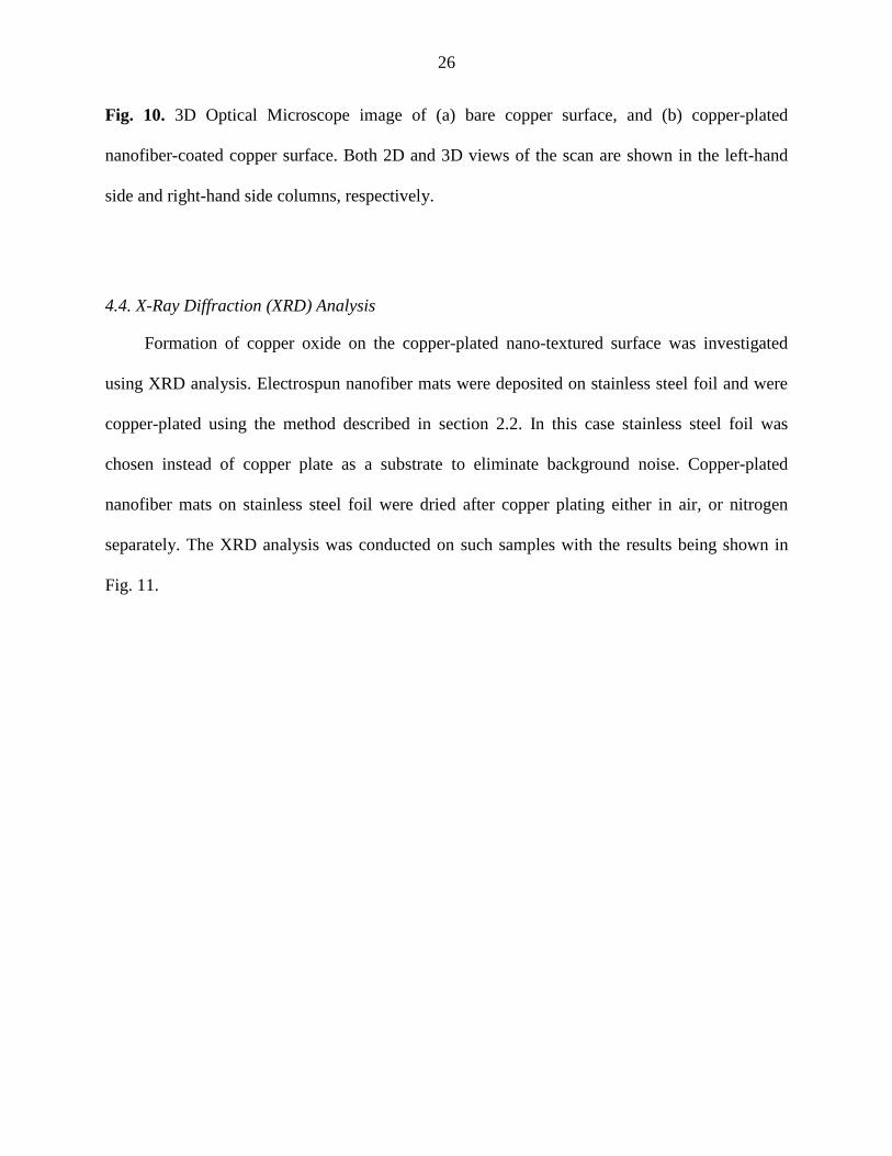
Figure 10a shows representative 2D and 3D images of the bare copper surface. The scratches on
the bare copper surface result from rubbing the sample with sandpaper. The roughness of the
copper-plated nanofibers deposited on the copper surface is higher, cf. Table 1. Three samples
were observed under the 3D optical microscope both before and after pool boiling experiments
and 15 different spots over each sample were chosen for statistical averaging of the roughness
parameters. Plating of copper crystals on nanofibers resulted in an increase in roughness of the
nanofiber layer which can be seen in Fig. 10b. After pool boiling on the same sample for several
hours the roughness of the nanofiber layer slightly (statistically insignificantly) decreased. It
should be emphasized that such decrease in roughness did not cause any change in the heat
transfer characteristics of the samples which is clearly evident from the repeatability of the
boiling curve in Fig. 2a. Differences in the corresponding values of Ra and Rq in Table 1 signify
the unevenness of the underlying bare copper surface and copper-plated nano-textured surface.

25
The above-mentioned slight decrease in roughness of the copper-plated nanofiber layer can
be attributed to the following reasons. First, during the initial degasification process when the
copper substrate is heated for 50 min, the nano-textured nanofiber layers gets partially sintered
[41-43], which causes a decrease in thickness. Second, due to prolong pool boiling experiments
the metallic Cu on the nanofibers can be oxidized to form copper (I) oxide. The formation of
Cu2O from Cu can facilitate lattice diffusion [44], later favoring annealing of the oxide layer to
form large grains and a smoother surface. This is also seen as a reduction of the elevation of Cu
plating on the nanofibers (cf. Table 1). Both reasons can cause an overall decrease in the
thickness of the metal coating on nanofibers to some extent.
(a)
(b)
26
Fig. 10. 3D Optical Microscope image of (a) bare copper surface, and (b) copper-plated
nanofiber-coated copper surface. Both 2D and 3D views of the scan are shown in the left-hand
side and right-hand side columns, respectively.
4.4. X-Ray Diffraction (XRD) Analysis
Formation of copper oxide on the copper-plated nano-textured surface was investigated
using XRD analysis. Electrospun nanofiber mats were deposited on stainless steel foil and were
copper-plated using the method described in section 2.2. In this case stainless steel foil was
chosen instead of copper plate as a substrate to eliminate background noise. Copper-plated
nanofiber mats on stainless steel foil were dried after copper plating either in air, or nitrogen
separately. The XRD analysis was conducted on such samples with the results being shown in
Fig. 11.

27
Fig. 11. XRD analysis of copper-plated nanofibers collected on stainless steel foil and dried after
copper-plating in (a) air, or (b) nitrogen atmosphere. The presence of peaks corresponding to d-
spacing of 2.465 o
A and 1.509 o
A indicates formation of cuprite (Cu2O), an oxide of copper.
The formation of copper oxide in contact with air is evident from the characteristic peak of
cuprite (cf. Fig. 11a) in distinction from the sample dried in nitrogen atmosphere where the
cuprite peak is absent (cf. Fig. 11b). However, after a copper-plated nanofiber mat dried in
Cu2O(a)
(b)
Cu2O

28
nitrogen atmosphere was subsequently dipped in boiling water for 30 min and then dried in air,
the XRD analysis revealed the presence of cuprite (cf. Fig 12). Boiling in water facilitates
oxidation of copper-plated nanofibers.
Fig. 12. XRD pattern of copper-plated nanofibers collected on a stainless steel foil, dried in
nitrogen atmosphere and subsequently immersed in boiling water for 30 min and then dried in
air. The presence of a peak corresponding to a d-spacing of 2.465o
A in panel (a) indicates
(a)
(b)
Cu2O
29
formation of cuprite (Cu2O). The XRD pattern of bare stainless steel foil without such a peak is
shown for control in panel (b).
5. Conclusion
Pool boiling of Novec FC 7300 fluid, pure water and self-rewetting water-heptanol mixture
was conducted on both bare copper surface and copper-plated nanofiber nano-textured surface.
The heat flux (the heat removal rate) and the corresponding heat transfer coefficient were found
to be higher on the copper-plated nanofiber surface. The pool boiling data for the self-rewetting
fluid revealed a higher heat removal rate from the nano-textured surfaces than even the one for
pure water. The XRD analysis of the copper-plated nanofiber surfaces before and after pool
boiling of water revealed oxidation of copper and formation of copper oxide on the surface. The
nature of the plated material (either copper oxide or copper) on nanofiber surface did not affect
the characteristics of pool boiling over such surface. The roughness of the copper-plated
nanofiber surface slightly (and statistically insignificant) decreases as a result of prolong pool
boiling experiments due to both sintering of the nano-textures and formation of the oxide layer
over the nano-textures.
Achnowledgement
This work is supported by NASA (Grant No. NNX13AQ77G). The help of Mr. Vadim Drozd is
gratefully appreciated.

30
References
1. G. E. Moore, Cramming more components onto integrated circuits. Electronics, 38 (1965)
114-117.
2. The Green500 List. http://www.green500.org, Nov 2010.
3. S. Nukiyama, The maximum and minimum values of the heat Q transmitted from metal to
boiling water under atmospheric pressure. Int. J. Heat Mass Transfer 9(12) (1966) 1419-1433.
4. R. Rioboo, M. Marengo, S. Dall’Olio, M. Voué and J. De Coninck, An innovative method to
control the incipient flow boiling through grafted surfaces with chemical patterns, Langmuir, 25
(2009) 6005-6009.
5. L. Dong, X. Quan and P. Cheng, An experimental investigation of enhanced pool boiling
heat transfer from surfaces with micro/nano-structures, Int. J. Heat Mass Transfer, 71 (2014)
189-196.
6. C. Li and G.P. Peterson, Geometric effects on critical heat flux on horizontal microporous
coatings, J. Thermophys Heat Transfer, 24 (2010) 449-455.
7. K.N.Rainey and S.M. You, Pool boiling heat transfer from plain and microporous, square pin-
finned surfaces in saturated FC-72, J. Heat Transfer, 122 (2000) 509-516.
8. J.P. McHale, S.V. Garimella, T.S. Fisher and G.A. Powell. Pool boiling performance
comparison of smooth and sintered copper surfaces with and without carbon nanotubes,
Nanoscale and Microscale Thermophysical Engineering 15 2011 133-150.

31
9. H.K. Forster and R. Greif, Heat transfer to a boiling liquid-mechanism and correlations, J.
Heat Transfer, 81 (1959) 43-53.
10. B.B. Mikic and W.M. Rohsenow, A new correlation of pool-boiling data including the effect
of heating surface characteristics, J. Heat Transfer, 91 (1969) 245-250.
11. N. Zuber, Hydrodynamic aspects of boiling heat transfer (thesis) (No. AECU-4439).
California. Univ., Los Angeles; and Ramo-Wooldridge Corp., Los Angeles (1959).
12. V.P. Carey, Liquid-Vapor Phase-Change Phenomena. Second Ed., Taylor & Francis,
New York, 287-292, 2008.
13. J.H. Lienhard and V.K. Dhir, Extended hydrodynamic theory of the peak and minimum pool
boiling heat fluxes. NASA, 2270 (1973).
14. R.L. Webb and N.H. Kim, Principles of Enhanced Heat Transfer, Second Ed., Taylor &
Francis, New York, 2005 pp. 389-391.
15. C. Gerardi, J. Buongiorno, L. W. Hu and T. McKrell, Experimental observation of the
dynamic micro-and macro-layer during pool boiling, ASME 2008 Heat Transfer Summer
Conference collocated with the Fluids Engineering, Energy Sustainability, and 3rd Energy
Nanotechnology Conferences. American Society of Mechanical Engineers, 2008 185-191.
16. S. M. You, J. H. Kim and K. H. Kim, Effect of nanoparticles on critical heat flux of water in
pool boiling heat transfer, Applied Physics Letters 83(16) (2003) 3374-3376.
17. H. Kim and M. Kim, Experimental study of the characteristics and mechanism of pool
boiling CHF enhancement using nanofluids, Heat Mass Transfer, 45 (2009) 991-998.

32
18. H. S. Ahn, J. M. Kim, C. Park, J. W. Jang, J. S. Lee, H. Kim, M. Kaviany and M. H. Kim, A
novel role of three dimensional graphene foam to prevent heater failure during boiling, Scientific
Reports 3 (2013) article 1960.
19. B. Bourdon, P. D. Marco, R. Rioboo, M. Marengo and J. D. Coninck, Enhancing the onset
of pool boiling by wettability modification on nanometrically smooth surfaces, International
Communications in Heat and Mass Transfer 45 (2013) 11-15.
20. Y. Nam, J. Wu, G. Warrier and Y. S. Ju, Experimental and numerical study of single bubble
dynamics on a hydrophobic surface, Journal of Heat Transfer 131 (2009) 121004.
21. O. C. Thomas, R. E. Cavicchi and M. J. Tarlov, Effect of surface wettability on fast transient
microboiling behavior, Langmuir 19 (2003) 6168-6177.
22. I. Malavasi, B. Bourdon, P. D. Marco, J. D. Coninck and M. Marengo, Appearance of a low
superheat “quasi-Leidenfrost” regime for boiling on superhydrophobic surfaces, International
Communications in Heat and Mass Transfer 63 (2015) 1-7.
23. A. Sathyanarayana, P. Warrier, Y. Im, Y. Joshi and A. S. Teja, Pool boiling of HFE 7200–
C4H4F6O mixture on hybrid micro-nanostructured surface, Journal of Nanotechnology in
Engineering and Medicine 3 (2012) 041004.
24. Forrest, E. C., Hu, L. W., Buongiorno, J. and T.J. McKrell, Pool boiling heat transfer
performance of a dielectric fluid with low global warming potential. Heat Transfer Engineering,
34 (2013) 1262-1277.
33
25. J. P. McHale, S. V. Garimella, T. S. Fisher and G. A. Powell, Pool boiling performance
comparison of smooth and sintered copper surfaces with and without carbon nanotubes,
Nanoscale and Microscale Thermophysical Engineering, 15 (2011) 133-150.
26. M. J. Rau and S. V. Garimella, Confined jet impingement with boiling on a variety of
enhanced surfaces, J. Heat Transfer, 136 (2014) 101503.
27. S. Nils, P. Di Marco and P. Stephan, Investigation of wall temperature and heat flux
distribution during nucleate boiling in the presence of an electric field and in variable gravity,
Experimental Thermal and Fluid Science, 44 (2013) 419-430.
28. P. Di Marco, Review of reduced gravity boiling heat transfer: European research, J. Jpn. Soc.
Microgravity Appl., 20 (2003) 252-263.
29. Y. Hu, S. Zhang, X. Li and S. Wang, Heat transfer enhancement of subcooled pool boiling
with self-rewetting fluid, Int. J. Heat Mass Transfer, 83 (2015) 64-68.
30. Y. Abe, Self‐rewetting fluids, Annals of the New York Academy of Sciences, 1077 (2006)
650-667.
31. Y. Hu, T. Liu, X. Li and S. Wang, Heat transfer enhancement of micro oscillating heat pipes
with self-rewetting fluid, Int. J. Heat Mass Transfer,70 (2014) 496-503.
32. S. Sinha-Ray, Y. Zhang and A.L. Yarin, Thorny devil nanotextured fibers: the way to cooling
rates on the order of 1 kW/cm2. Langmuir, 27 (2010) 215-226.
33. S. Sinha-Ray and A. L. Yarin, Drop impact cooling enhancement on nano-textured surfaces.
Part I: Theory and results of the ground (1g) experiments. Int. J. Heat Mass Transfer, 70 (2014)
1095-1106.
34
34. S. Sinha-Ray, S. Sinha-Ray, A. L. Yarin, C. M. Weickgenannt, J. Emmert and C. Tropea.
Drop impact cooling enhancement on nano-textured surfaces. Part II: Results of the parabolic
flight experiments [zero gravity (0 g) and supergravity (1.8 g)], Int. J. Heat Mass Transfer, 70
(2014) 1107-1114.
35. S. Jun, S. Sinha-Ray and A. L. Yarin. Pool boiling on nano-textured surfaces, International J.
Heat Transfer, 62 (2013) 99-111.
36. R. P. Sahu, S. Sinha-Ray, S. Sinha-Ray and A. L. Yarin, Pool boiling on nano-textured
surfaces comprised of electrically-assisted supersonically solution-blown, copper-plated
nanofibers: Experiments and theory, Int. J. Heat Mass Transfer, 87 (2015) 521-535.
37. S. An, C. Lee, M. Liou, H. S. Jo, J.-J. Park, A. L. Yarin and S. S. Yoon. Supersonically
blown ultra-thin thorny devil nanofibers for efficient air cooling. ACS Applied Materials
& Interfaces, 6 (2014) 13657-13666.
38. L. Dong, X. Quan and P. Cheng, An experimental investigation of enhanced pool boiling
heat transfer from surfaces with micro/nano-structures, Int. J. Heat Mass Transfer, 71 (2014)
189-196.
39. Y. Y. Li, Z. H. Liu and B. C. Zheng, Experimental study on the saturated pool boiling heat
transfer on nano-scale modification surface, Int. J. Heat Mass Transfer, 84 (2015) 550-561.
40. S. Chandrasekhar, Hydrodynamic and Hydromagnetic Stability. Oxford: Clarendon Press,
1970.
41. C. Kim, G. Lee, C. Rhee and M. Lee, Expeditious low-temperature sintering of copper
nanoparticles with thin defective carbon shells. Nanoscale, 7 (2015) 6627-6635.
42. S. Jang, Y. Seo, J. Choi, T. Kim, J. Cho, S. Kim and D. Kim, Sintering of inkjet printed
copper nanoparticles for flexible electronics. Scripta Materialia, 62 (2010) 258-261.

35
43. E. K. Yu, L. Piao and S. H. Kim, Sintering behavior of copper nanoparticles. Bull. Korean
Chem. Soc, 32 (2011) 4099-4102.
44. U. Nerle and M.K. Rabinal, Thermal oxidation of copper for favorable formation of cupric
oxide (CuO) semiconductor , IOSR J. Applied Physics, 5 (2013) 1-7.