Embed Size (px)
Citation preview
1
INSTALLATION AND OPERATING INSTRUCTIONS
CONNECT 10 IOM INST 314
Melbourne: 03 8796 8600 Gold Coast: 07 5552 2600 Perth: 08 9350 2600 North Sydney: 02 9853 2100 South Sydney: 02 8788 9500 Townsville: 07 4750 3100Brisbane: 07 3308 5400 Adelaide: 08 8152 7600 www.astralpool.com.au [email protected]
Bolero ND Cleaner
Viron Cartridge Filter
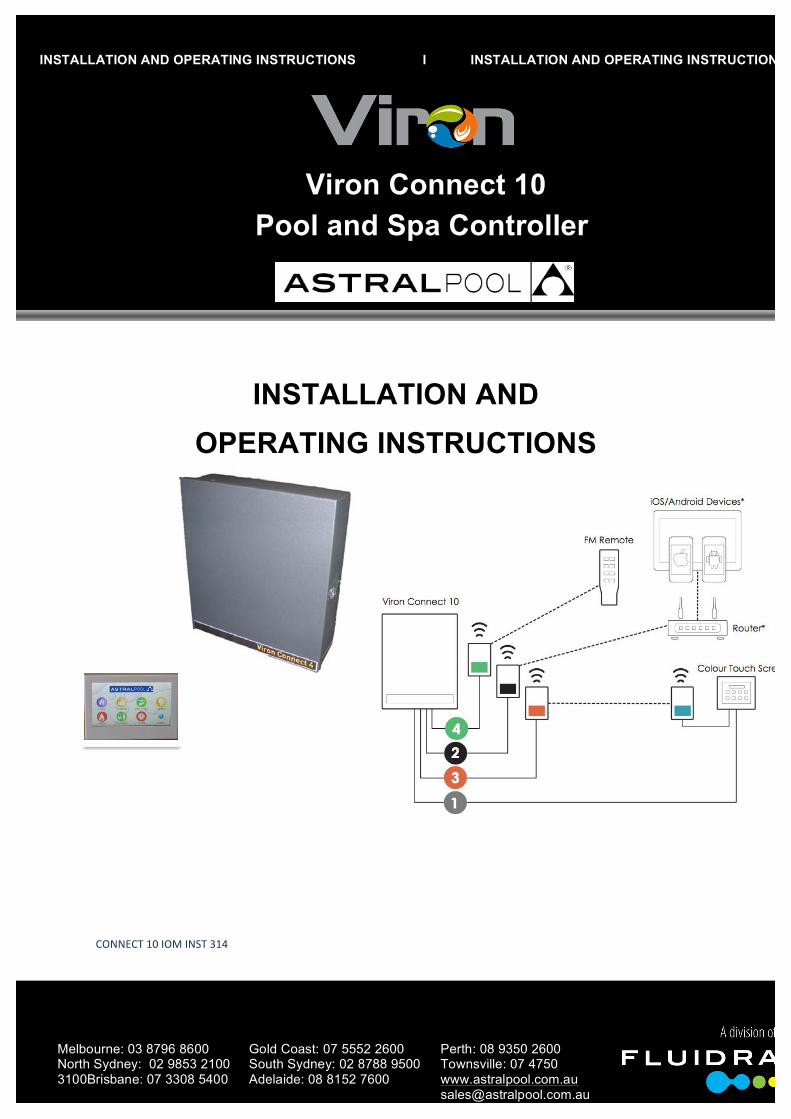
INSTALLATION AND OPERATING INSTRUCTIONS I INSTALLATION AND OPERATING INSTRUCTIONS
Viron Connect 10 Pool and Spa Controller
2
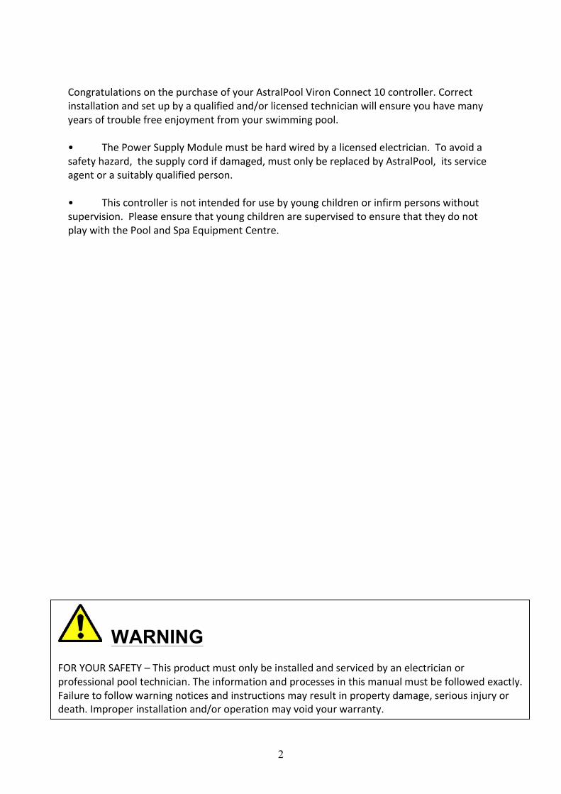
Congratulations on the purchase of your AstralPool Viron Connect 10 controller. Correct installation and set up by a qualified and/or licensed technician will ensure you have many years of trouble free enjoyment from your swimming pool. • The Power Supply Module must be hard wired by a licensed electrician. To avoid a safety hazard, the supply cord if damaged, must only be replaced by AstralPool, its service agent or a suitably qualified person. • This controller is not intended for use by young children or infirm persons without supervision. Please ensure that young children are supervised to ensure that they do not play with the Pool and Spa Equipment Centre.
WARNING FOR YOUR SAFETY – This product must only be installed and serviced by an electrician or professional pool technician. The information and processes in this manual must be followed exactly. Failure to follow warning notices and instructions may result in property damage, serious injury or death. Improper installation and/or operation may void your warranty.
3
Table of Contents Section 1 Overview ...................................................................................................................................................... 4
Components ...................................................................................................................................................................... 4
Basic Operation ................................................................................................................................................................. 4
Section 2 Equipment Operation ................................................................................................................................... 5
Pool & Spa ......................................................................................................................................................................... 5
Lighting .............................................................................................................................................................................. 5
Heating .............................................................................................................................................................................. 6
Solar .................................................................................................................................................................................. 6
Favourites .......................................................................................................................................................................... 7
Section 3 Setting the Clock ........................................................................................................................................... 8
Clock setting ...................................................................................................................................................................... 8
Section 4 Timer Programming ...................................................................................................................................... 9
Setting timers .................................................................................................................................................................... 9
Section 5 Favourite Programming .............................................................................................................................. 15
Setting favourites ............................................................................................................................................................ 15
Section 6 Equipment Installation ................................................................................................................................ 17
Control box installation ................................................................................................................................................... 18
Touchscreen installation ................................................................................................................................................. 18
Equipment connection -‐ electrical .................................................................................................................................. 19
Equipment connection – data/communications ............................................................................................................. 20
Section 7 Installation Setup ........................................................................................................................................ 21
Touchscreen Setup .......................................................................................................................................................... 21
Section 8 Wireless Configuration ................................................................................................................................ 32
Wireless link installation ................................................................................................................................................. 32
RF Remote installation .................................................................................................................................................... 35
Section 9 External Heater Control………………………………………………………………………………………………………………….………….36 Section 10 Solar Control via motorsed valve…………………………………………………………………………………………………………….36 Section 11 Touch Screen Installation .......................................................................................................................... 37
Section 12 Customer Switching from an external Source ............................................................................................ 46
Section 13 Service Mode Operation ........................................................................................................................... 47
Section 14 Functionality Tips ...................................................................................................................................... 48
Section 15 Troubleshooting ........................................................................................................................................ 50
Section 16 Assigning outlets/channels ....................................................................................................................... 51
Warranty – Terms and Conditions .............................................................................................................................. 52
4
Table of Contents Part Two: Internet Gateway and Smart Phone App Installation Installing the Internet GateWay and Smart Phone/Tablet App……………………………………….…………………….................…..59 Installing internet gateway hardware to the Connect 10……………………………………………………………………………………………59 Configuring home WiFi…………………………………………………………………………………..…………………………………………………………61 Registering “Pool Owner” and authorized “Users”……………………………………………………………………………………….…………..64 Internet Serial Number and Password………………………………………………………………………………………………………………………65 Download connectmypool app to your SmartPhone or Tablet……………………………………………………………………….…………67 Internet Gateway and App trouble shooting……………………………………………………………………………………….……………………74
5
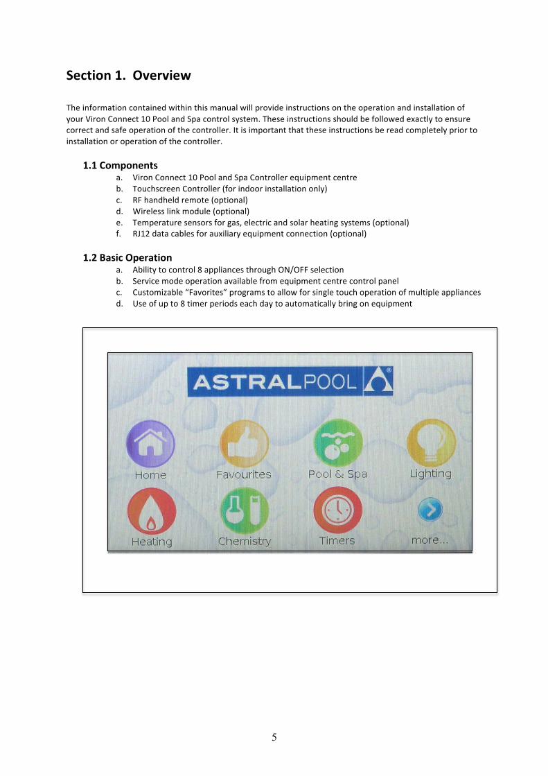
Section 1. Overview The information contained within this manual will provide instructions on the operation and installation of your Viron Connect 10 Pool and Spa control system. These instructions should be followed exactly to ensure correct and safe operation of the controller. It is important that these instructions be read completely prior to installation or operation of the controller.
1.1 Components a. Viron Connect 10 Pool and Spa Controller equipment centre b. Touchscreen Controller (for indoor installation only) c. RF handheld remote (optional) d. Wireless link module (optional) e. Temperature sensors for gas, electric and solar heating systems (optional) f. RJ12 data cables for auxiliary equipment connection (optional)
1.2 Basic Operation
a. Ability to control 8 appliances through ON/OFF selection b. Service mode operation available from equipment centre control panel c. Customizable “Favorites” programs to allow for single touch operation of multiple appliances d. Use of up to 8 timer periods each day to automatically bring on equipment
6
Section 2. Equipment Operation All appliances on your Viron Connect controller can be easily operated through the specific product screens
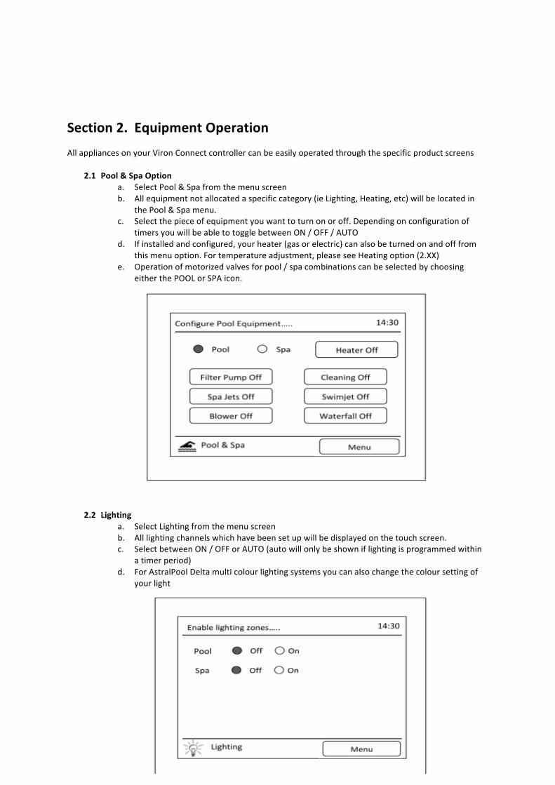
2.1 Pool & Spa Option a. Select Pool & Spa from the menu screen b. All equipment not allocated a specific category (ie Lighting, Heating, etc) will be located in
the Pool & Spa menu. c. Select the piece of equipment you want to turn on or off. Depending on configuration of
timers you will be able to toggle between ON / OFF / AUTO d. If installed and configured, your heater (gas or electric) can also be turned on and off from
this menu option. For temperature adjustment, please see Heating option (2.XX) e. Operation of motorized valves for pool / spa combinations can be selected by choosing
either the POOL or SPA icon.
2.2 Lighting a. Select Lighting from the menu screen b. All lighting channels which have been set up will be displayed on the touch screen. c. Select between ON / OFF or AUTO (auto will only be shown if lighting is programmed within
a timer period) d. For AstralPool Delta multi colour lighting systems you can also change the colour setting of
your light
7
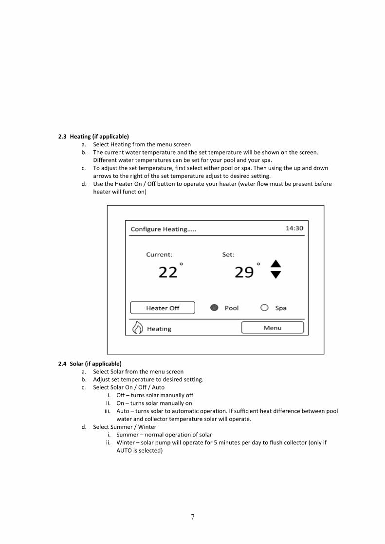
2.3 Heating (if applicable)
a. Select Heating from the menu screen b. The current water temperature and the set temperature will be shown on the screen.
Different water temperatures can be set for your pool and your spa. c. To adjust the set temperature, first select either pool or spa. Then using the up and down
arrows to the right of the set temperature adjust to desired setting. d. Use the Heater On / Off button to operate your heater (water flow must be present before
heater will function)
2.4 Solar (if applicable) a. Select Solar from the menu screen b. Adjust set temperature to desired setting. c. Select Solar On / Off / Auto
i. Off – turns solar manually off ii. On – turns solar manually on iii. Auto – turns solar to automatic operation. If sufficient heat difference between pool
water and collector temperature solar will operate. d. Select Summer / Winter
i. Summer – normal operation of solar ii. Winter – solar pump will operate for 5 minutes per day to flush collector (only if
AUTO is selected)
8
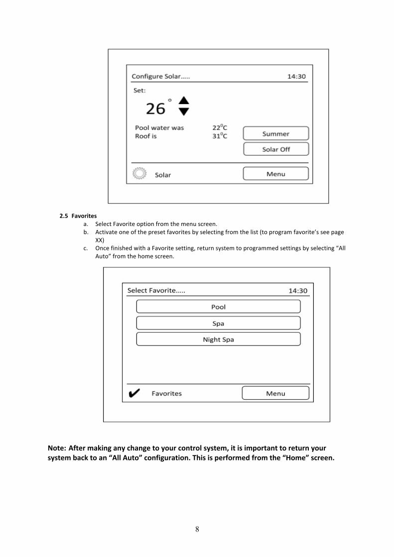
2.5 Favorites
a. Select Favorite option from the menu screen. b. Activate one of the preset favorites by selecting from the list (to program favorite’s see page
XX) c. Once finished with a Favorite setting, return system to programmed settings by selecting “All
Auto” from the home screen. Note: After making any change to your control system, it is important to return your system back to an “All Auto” configuration. This is performed from the “Home” screen.
9
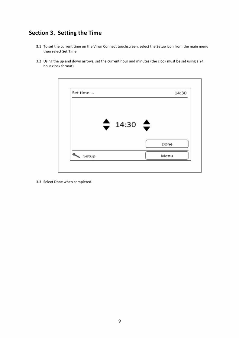
Section 3. Setting the Time
3.1 To set the current time on the Viron Connect touchscreen, select the Setup icon from the main menu then select Set Time.
3.2 Using the up and down arrows, set the current hour and minutes (the clock must be set using a 24
hour clock format)
3.3 Select Done when completed.
10
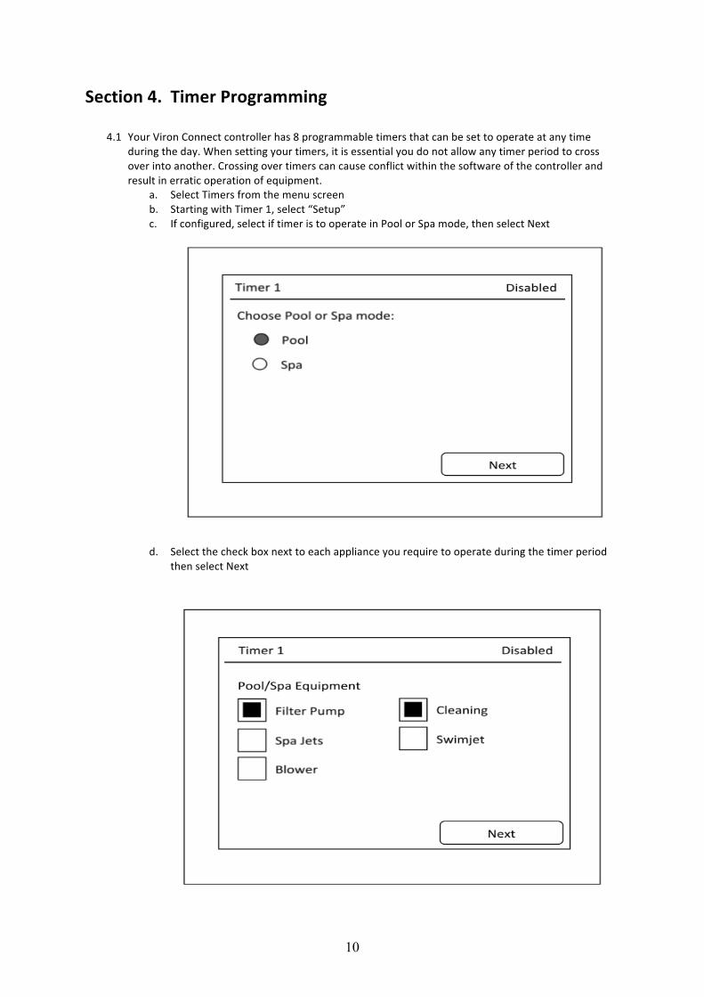
Section 4. Timer Programming
4.1 Your Viron Connect controller has 8 programmable timers that can be set to operate at any time during the day. When setting your timers, it is essential you do not allow any timer period to cross over into another. Crossing over timers can cause conflict within the software of the controller and result in erratic operation of equipment.
a. Select Timers from the menu screen b. Starting with Timer 1, select “Setup” c. If configured, select if timer is to operate in Pool or Spa mode, then select Next
d. Select the check box next to each appliance you require to operate during the timer period then select Next
11
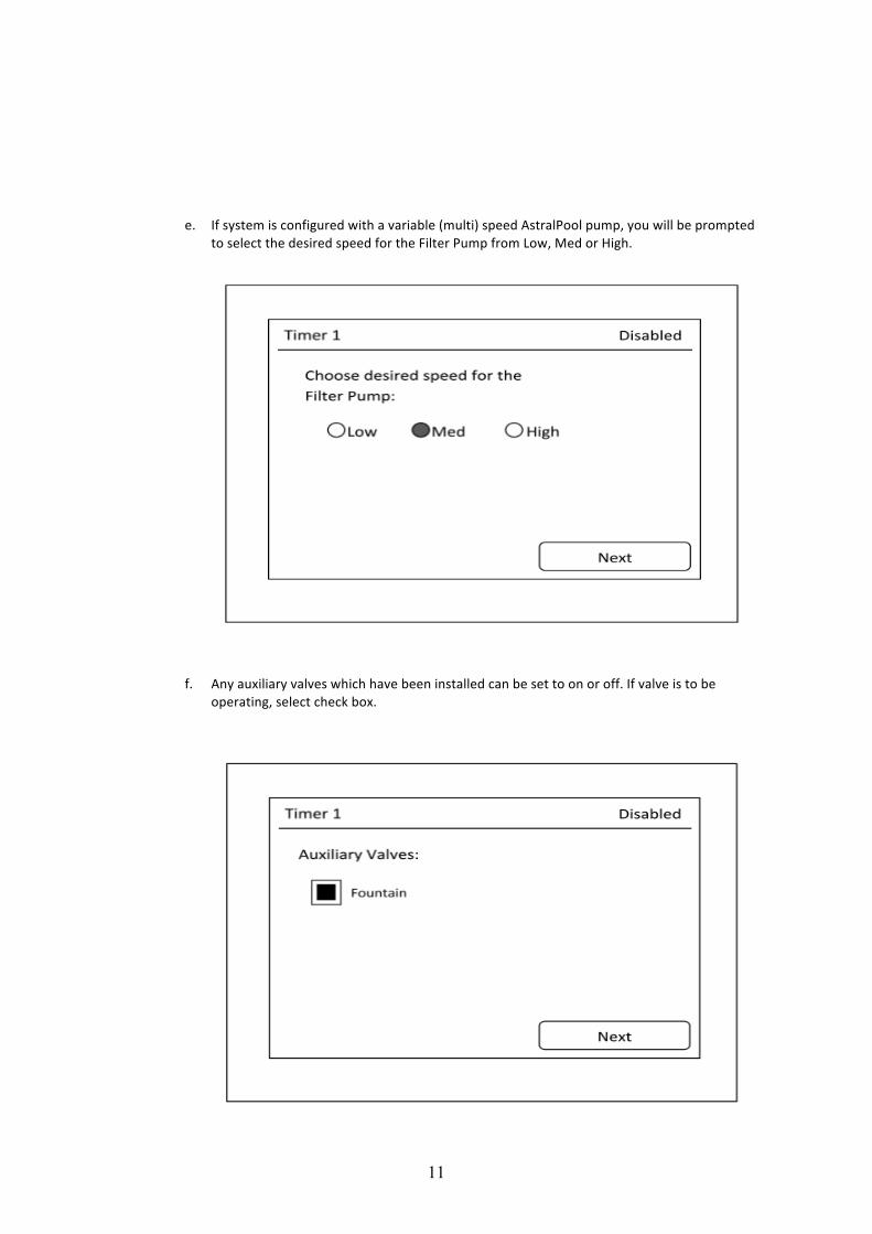
e. If system is configured with a variable (multi) speed AstralPool pump, you will be prompted
to select the desired speed for the Filter Pump from Low, Med or High.
f. Any auxiliary valves which have been installed can be set to on or off. If valve is to be operating, select check box.
12
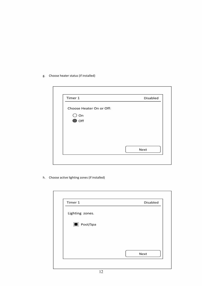
g. Choose heater status (if installed)
h. Choose active lighting zones (if installed)
13
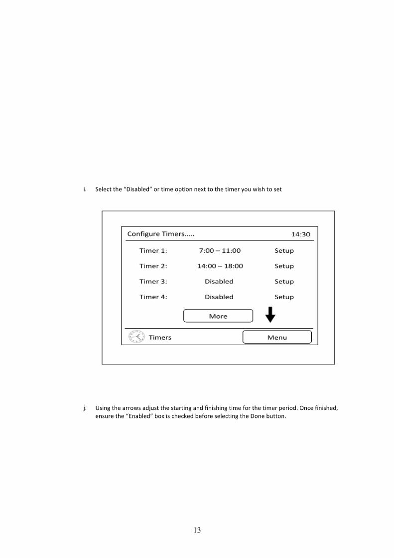
i. Select the “Disabled” or time option next to the timer you wish to set
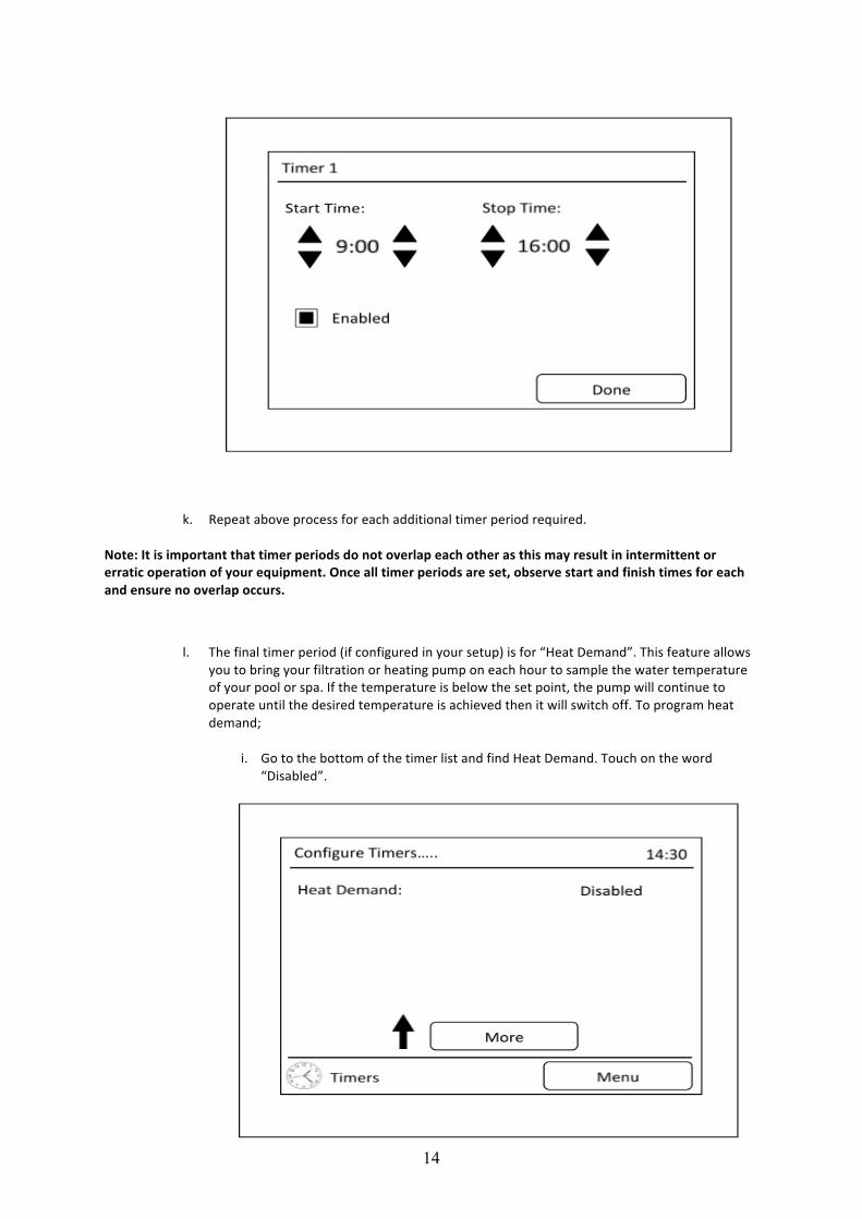
j. Using the arrows adjust the starting and finishing time for the timer period. Once finished, ensure the “Enabled” box is checked before selecting the Done button.
14
k. Repeat above process for each additional timer period required. Note: It is important that timer periods do not overlap each other as this may result in intermittent or erratic operation of your equipment. Once all timer periods are set, observe start and finish times for each and ensure no overlap occurs.
l. The final timer period (if configured in your setup) is for “Heat Demand”. This feature allows
you to bring your filtration or heating pump on each hour to sample the water temperature of your pool or spa. If the temperature is below the set point, the pump will continue to operate until the desired temperature is achieved then it will switch off. To program heat demand;
i. Go to the bottom of the timer list and find Heat Demand. Touch on the word
“Disabled”.
15
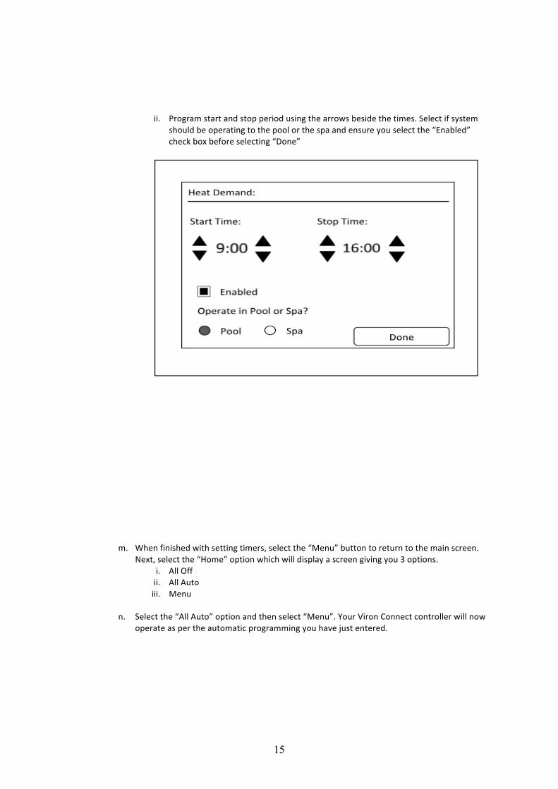
ii. Program start and stop period using the arrows beside the times. Select if system should be operating to the pool or the spa and ensure you select the “Enabled” check box before selecting “Done”
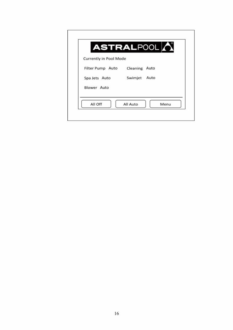
m. When finished with setting timers, select the “Menu” button to return to the main screen.
Next, select the “Home” option which will display a screen giving you 3 options. i. All Off ii. All Auto iii. Menu
n. Select the “All Auto” option and then select “Menu”. Your Viron Connect controller will now
operate as per the automatic programming you have just entered.
16
17
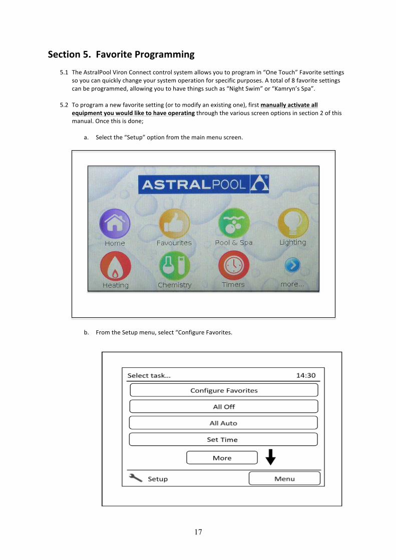
Section 5. Favorite Programming
5.1 The AstralPool Viron Connect control system allows you to program in “One Touch” Favorite settings so you can quickly change your system operation for specific purposes. A total of 8 favorite settings can be programmed, allowing you to have things such as “Night Swim” or “Kamryn’s Spa”.
5.2 To program a new favorite setting (or to modify an existing one), first manually activate all
equipment you would like to have operating through the various screen options in section 2 of this manual. Once this is done;
a. Select the “Setup” option from the main menu screen.
b. From the Setup menu, select “Configure Favorites.
18
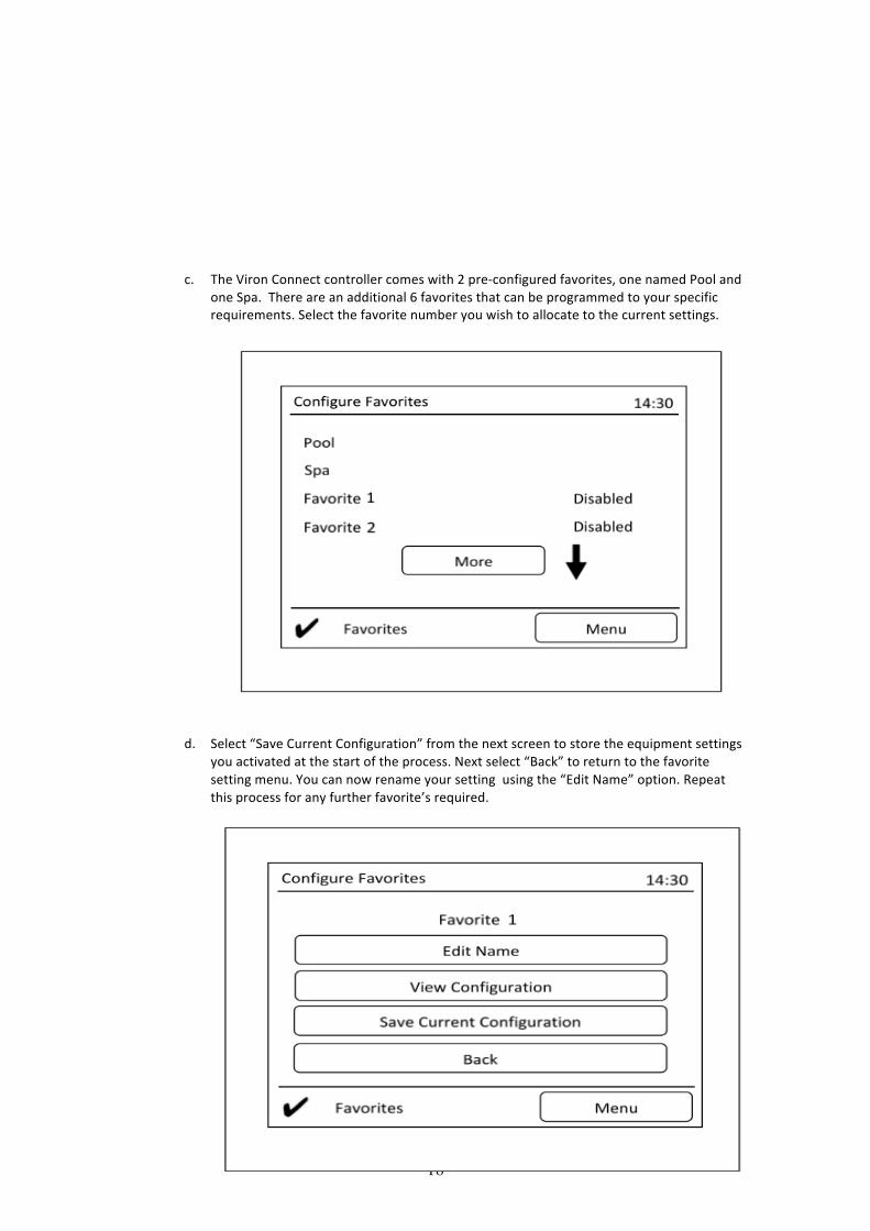
c. The Viron Connect controller comes with 2 pre-‐configured favorites, one named Pool and
one Spa. There are an additional 6 favorites that can be programmed to your specific requirements. Select the favorite number you wish to allocate to the current settings.
d. Select “Save Current Configuration” from the next screen to store the equipment settings you activated at the start of the process. Next select “Back” to return to the favorite setting menu. You can now rename your setting using the “Edit Name” option. Repeat this process for any further favorite’s required.
19
WARNING FOR YOUR SAFETY – This product must only be installed and serviced by an electrician or professional pool technician. The information and processes in this manual must be followed exactly. Failure to follow warning notices and instructions may result in property damage, serious injury or death. Improper installation and/or operation may void your warranty.
e. Finally, select Enabled or Disabled for each favorite setting by touching the word to the right of each program.
Section 6. Equipment Installation
This appliance must be installed in accordance with AS/NZS 3000:2007 and any other local regulations. All equipment to be operated from the Viron controller should be connected prior to establishing power to the control box. This includes both power cables and RJ12 data cables. All RJ12 data cables used in AstralPool communication systems are a straight through configuration. The use of cross over cables may cause damage to your system and void warranty. The combined total load all equipment connected to the Viron controller must not exceed 40 amps. An approved isolation switch must be installed in the electrical line to the Viron Connect controller. This switch must be positioned in close proximity to the control box. The Viron Connect control system is not intended for use by young children or infirm persons without supervision. Please ensure that young children are supervised to ensure they do not play with the controller. The control box must be hard wired by a licensed electrician. To avoid a safety hazard, the supply cord if damaged must only be replaced by AstralPool, its service agent or a suitably qualified person. Power to the control box should be supplied by an isolating transformer or through a residual current device (RCD) with a rated residual operating current not exceeding 30mA. The touchscreen control for the Viron Connect is for INDOOR installation only. Installation of the touchscreen outside or where exposed to the elements will void warranty.
20
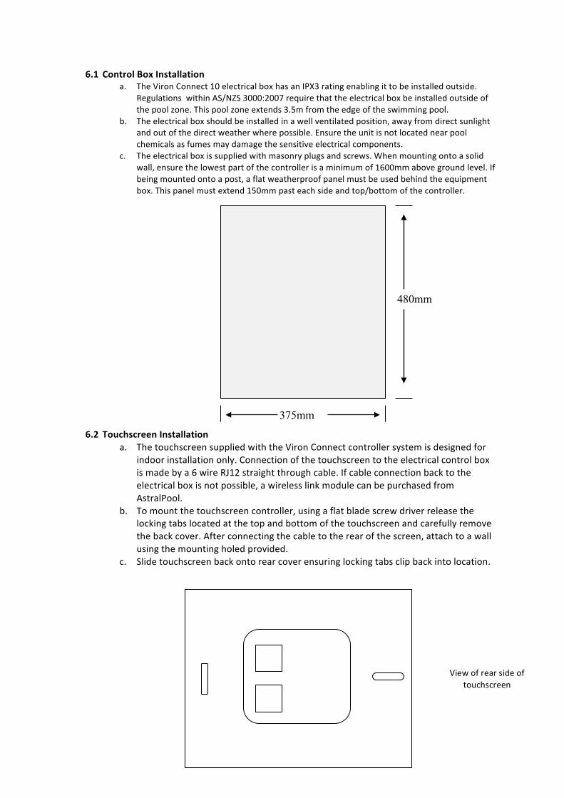
6.1 Control Box Installation a. The Viron Connect 10 electrical box has an IPX3 rating enabling it to be installed outside.
Regulations within AS/NZS 3000:2007 require that the electrical box be installed outside of the pool zone. This pool zone extends 3.5m from the edge of the swimming pool.
b. The electrical box should be installed in a well ventilated position, away from direct sunlight and out of the direct weather where possible. Ensure the unit is not located near pool chemicals as fumes may damage the sensitive electrical components.
c. The electrical box is supplied with masonry plugs and screws. When mounting onto a solid wall, ensure the lowest part of the controller is a minimum of 1600mm above ground level. If being mounted onto a post, a flat weatherproof panel must be used behind the equipment box. This panel must extend 150mm past each side and top/bottom of the controller.
6.2 Touchscreen Installation a. The touchscreen supplied with the Viron Connect controller system is designed for
indoor installation only. Connection of the touchscreen to the electrical control box is made by a 6 wire RJ12 straight through cable. If cable connection back to the electrical box is not possible, a wireless link module can be purchased from AstralPool.
b. To mount the touchscreen controller, using a flat blade screw driver release the locking tabs located at the top and bottom of the touchscreen and carefully remove the back cover. After connecting the cable to the rear of the screen, attach to a wall using the mounting holed provided.
c. Slide touchscreen back onto rear cover ensuring locking tabs clip back into location.
375mm
480mm
View of rear side of touchscreen

21
76mm centers
22
Constant 240V supply
Channel 2
Channel 4
Channel 6
Channel 8 – 15A
Channel 1
Channel 3
Channel 5
Channel 7 – 15A
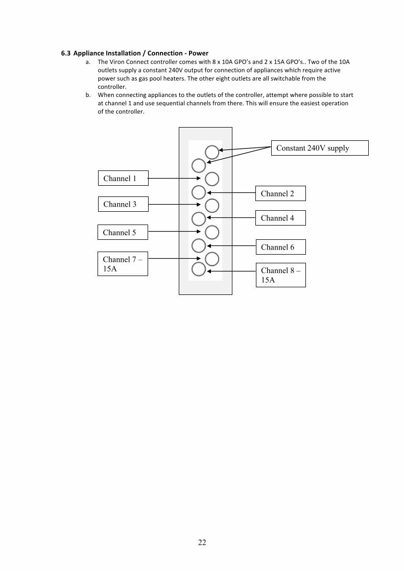
6.3 Appliance Installation / Connection -‐ Power a. The Viron Connect controller comes with 8 x 10A GPO’s and 2 x 15A GPO’s.. Two of the 10A
outlets supply a constant 240V output for connection of appliances which require active power such as gas pool heaters. The other eight outlets are all switchable from the controller.
b. When connecting appliances to the outlets of the controller, attempt where possible to start at channel 1 and use sequential channels from there. This will ensure the easiest operation of the controller.
23
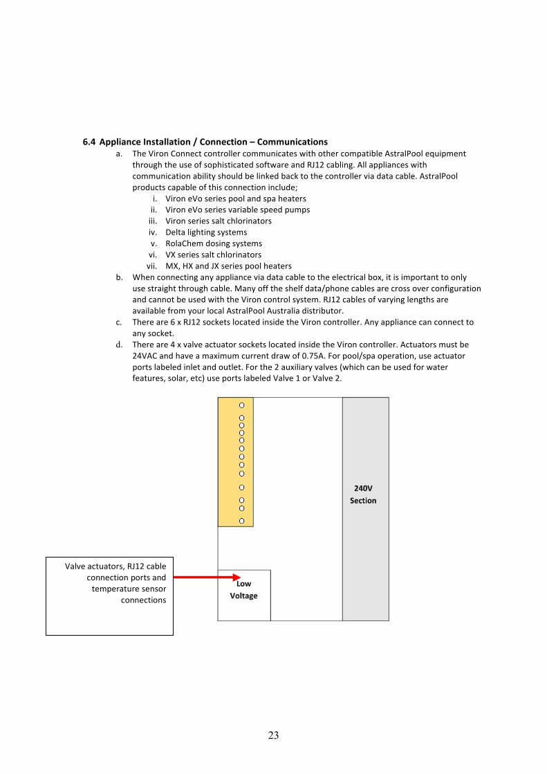
6.4 Appliance Installation / Connection – Communications
a. The Viron Connect controller communicates with other compatible AstralPool equipment through the use of sophisticated software and RJ12 cabling. All appliances with communication ability should be linked back to the controller via data cable. AstralPool products capable of this connection include;
i. Viron eVo series pool and spa heaters ii. Viron eVo series variable speed pumps iii. Viron series salt chlorinators iv. Delta lighting systems v. RolaChem dosing systems vi. VX series salt chlorinators vii. MX, HX and JX series pool heaters
b. When connecting any appliance via data cable to the electrical box, it is important to only use straight through cable. Many off the shelf data/phone cables are cross over configuration and cannot be used with the Viron control system. RJ12 cables of varying lengths are available from your local AstralPool Australia distributor.
c. There are 6 x RJ12 sockets located inside the Viron controller. Any appliance can connect to any socket.
d. There are 4 x valve actuator sockets located inside the Viron controller. Actuators must be 24VAC and have a maximum current draw of 0.75A. For pool/spa operation, use actuator ports labeled inlet and outlet. For the 2 auxiliary valves (which can be used for water features, solar, etc) use ports labeled Valve 1 or Valve 2.
Valve actuators, RJ12 cable connection ports and temperature sensor
connections
24
Section 7. Installation Setup
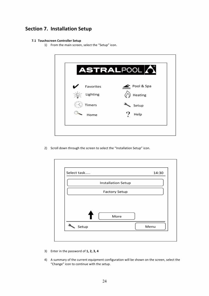
7.1 Touchscreen Controller Setup 1) From the main screen, select the “Setup” icon.
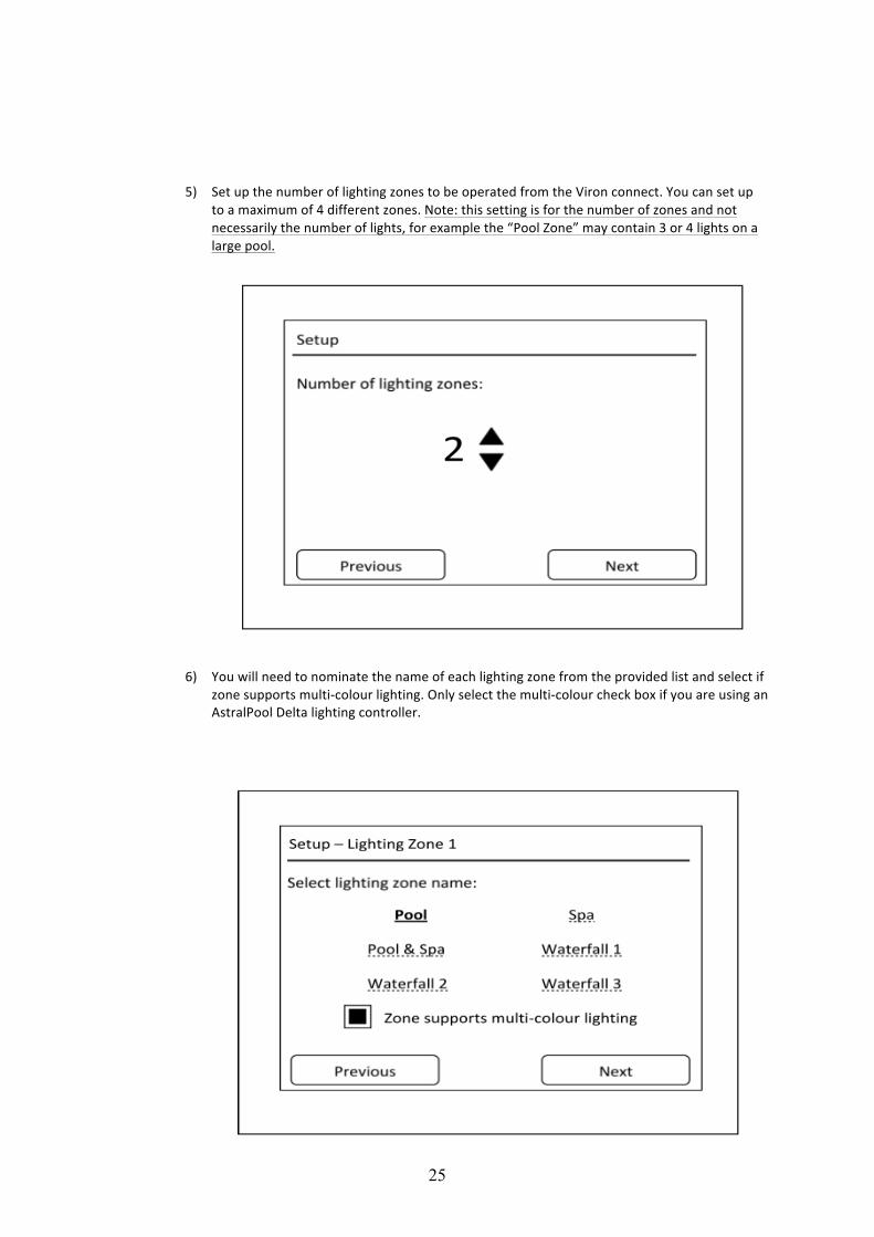
2) Scroll down through the screen to select the “Installation Setup” icon.
3) Enter in the password of 1, 2, 3, 4
4) A summary of the current equipment configuration will be shown on the screen, select the “Change” icon to continue with the setup.
25
5) Set up the number of lighting zones to be operated from the Viron connect. You can set up
to a maximum of 4 different zones. Note: this setting is for the number of zones and not necessarily the number of lights, for example the “Pool Zone” may contain 3 or 4 lights on a large pool.
6) You will need to nominate the name of each lighting zone from the provided list and select if zone supports multi-‐colour lighting. Only select the multi-‐colour check box if you are using an AstralPool Delta lighting controller.
26
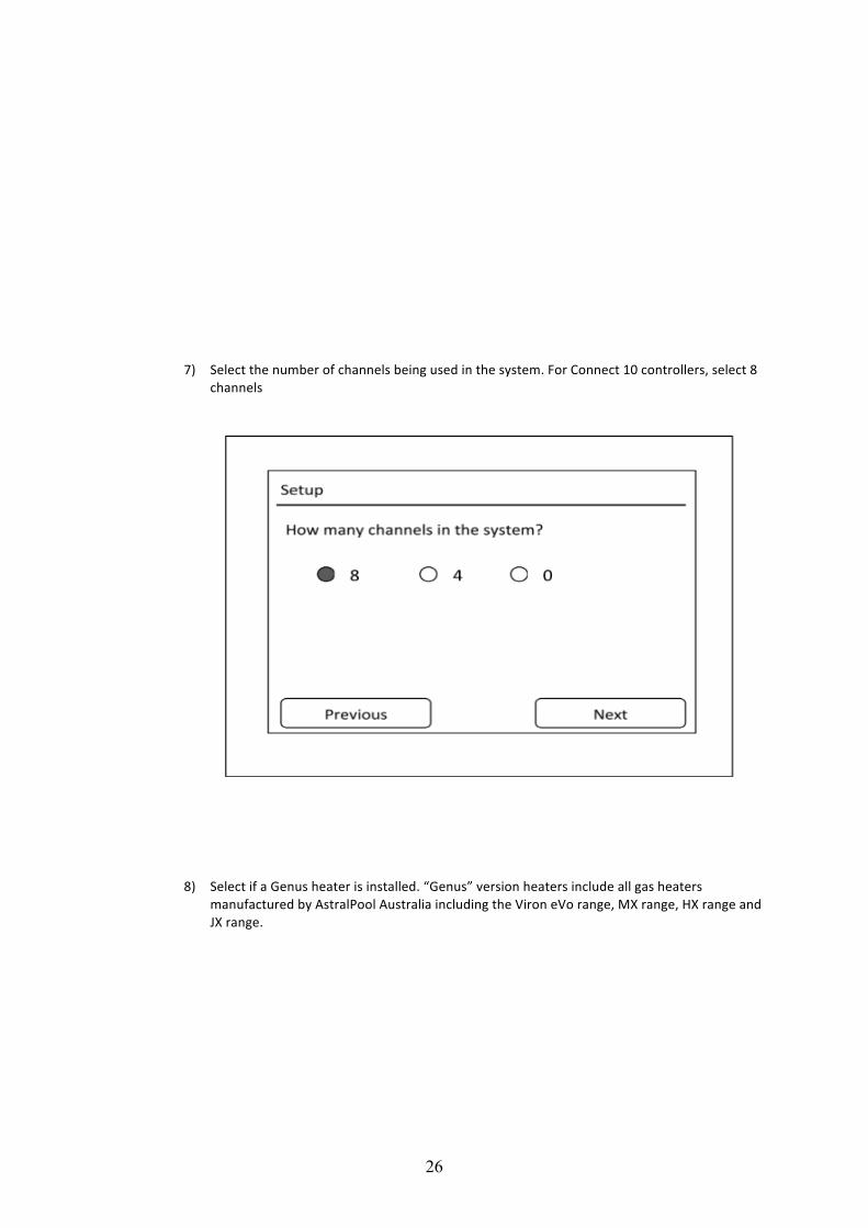
7) Select the number of channels being used in the system. For Connect 10 controllers, select 8
channels
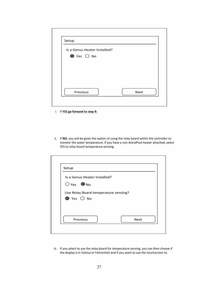
8) Select if a Genus heater is installed. “Genus” version heaters include all gas heaters manufactured by AstralPool Australia including the Viron eVo range, MX range, HX range and JX range.
27
i. If YES go forward to step 9;
ii. If NO, you will be given the option of using the relay board within the controller to
monitor the water temperature. If you have a non AstralPool heater attached, select YES to relay board temperature sensing;
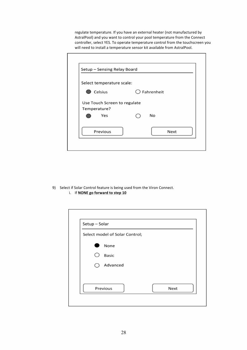
iii. If you select to use the relay board for temperature sensing, you can then choose if the display is in Celsius or Fahrenheit and if you want to use the touchscreen to
28
regulate temperature. If you have an external heater (not manufactured by AstralPool) and you want to control your pool temperature from the Connect controller, select YES. To operate temperature control from the touchscreen you will need to install a temperature sensor kit available from AstralPool.
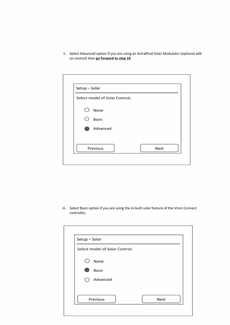
9) Select if Solar Control feature is being used from the Viron Connect.
i. If NONE go forward to step 10
29
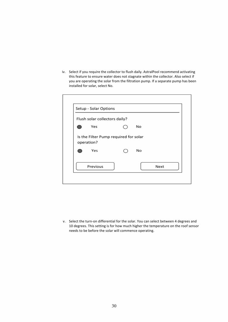
ii. Select Advanced option if you are using an AstralPool Solar Modulator (optional add on control) then go forward to step 10
iii. Select Basic option if you are using the in-‐built solar feature of the Viron Connect
controller;
30
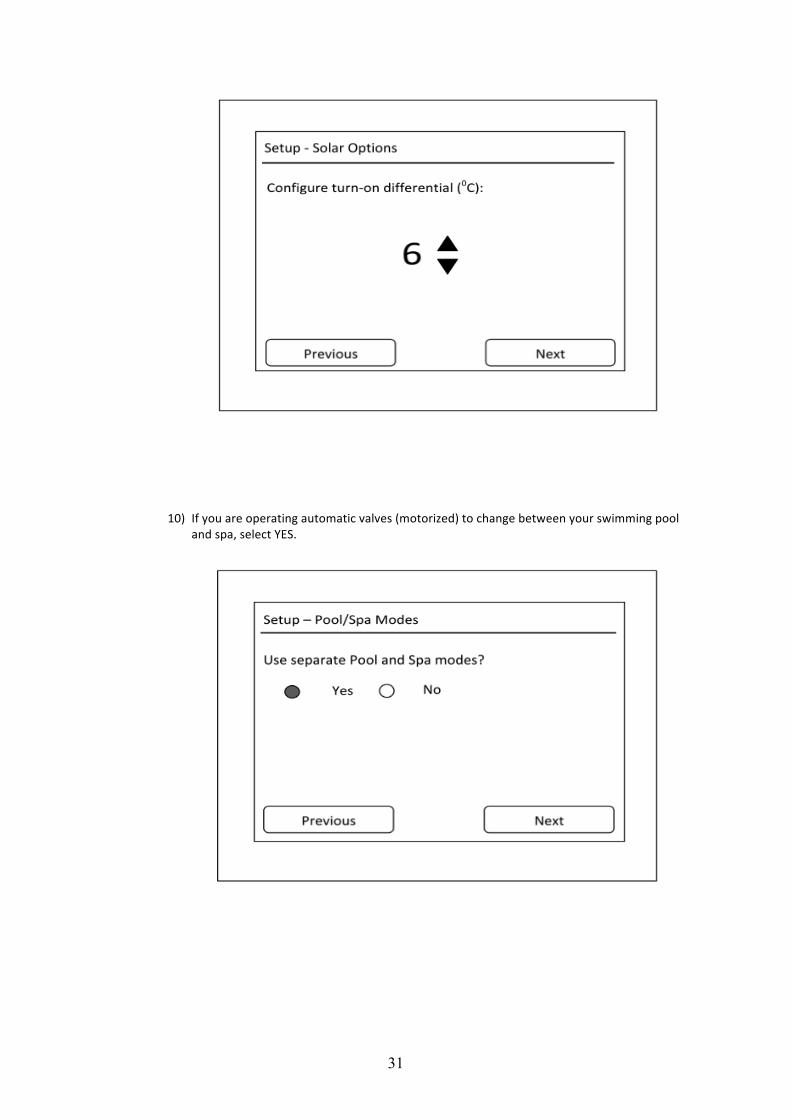
iv. Select if you require the collector to flush daily. AstralPool recommend activating this feature to ensure water does not stagnate within the collector. Also select if you are operating the solar from the filtration pump. If a separate pump has been installed for solar, select No.
v. Select the turn-‐on differential for the solar. You can select between 4 degrees and 10 degrees. This setting is for how much higher the temperature on the roof sensor needs to be before the solar will commence operating.
31
10) If you are operating automatic valves (motorized) to change between your swimming pool and spa, select YES.
32
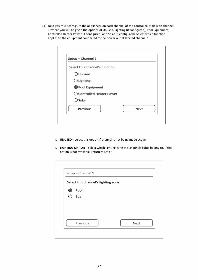
11) Next you must configure the appliances on each channel of the controller. Start with channel 1 where you will be given the options of Unused, Lighting (if configured), Pool Equipment, Controlled Heater Power (if configured) and Solar (if configured). Select which function applies to the equipment connected to the power outlet labeled channel 1
i. UNUSED – select this option if channel is not being made active
ii. LIGHTING OPTION – select which lighting zone this channels lights belong to. If this option is not available, return to step 5.
33
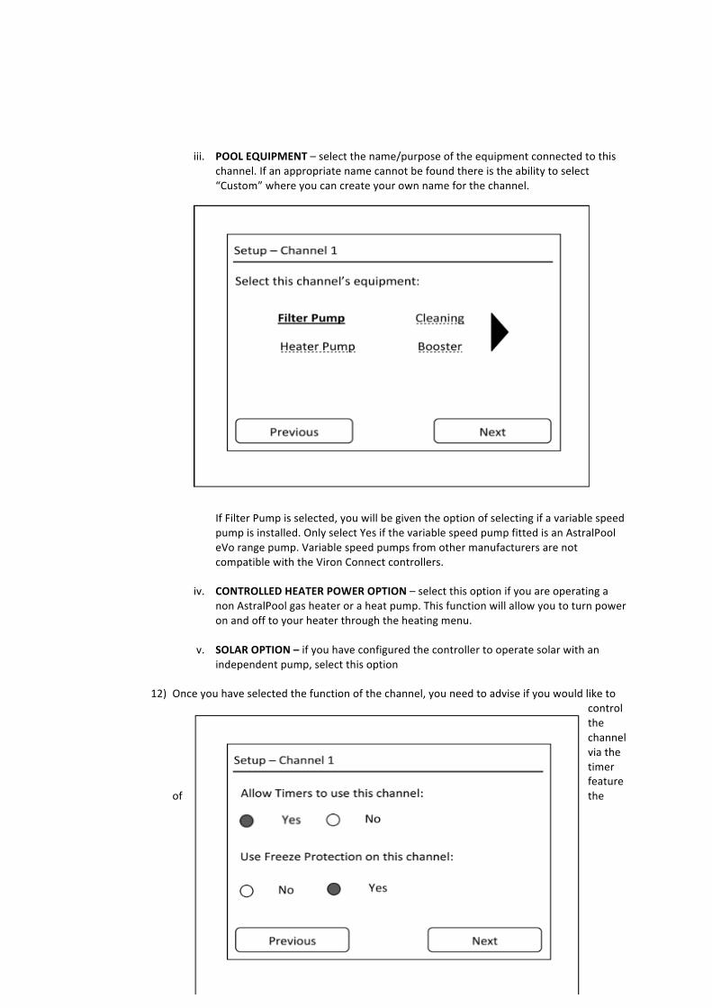
iii. POOL EQUIPMENT – select the name/purpose of the equipment connected to this
channel. If an appropriate name cannot be found there is the ability to select “Custom” where you can create your own name for the channel.
If Filter Pump is selected, you will be given the option of selecting if a variable speed pump is installed. Only select Yes if the variable speed pump fitted is an AstralPool eVo range pump. Variable speed pumps from other manufacturers are not compatible with the Viron Connect controllers.
iv. CONTROLLED HEATER POWER OPTION – select this option if you are operating a
non AstralPool gas heater or a heat pump. This function will allow you to turn power on and off to your heater through the heating menu.
v. SOLAR OPTION – if you have configured the controller to operate solar with an
independent pump, select this option
12) Once you have selected the function of the channel, you need to advise if you would like to control the channel via the timer feature
of the
34
Connect controller.
13) Repeat step 11 for each additional channel you have allocated in the system.
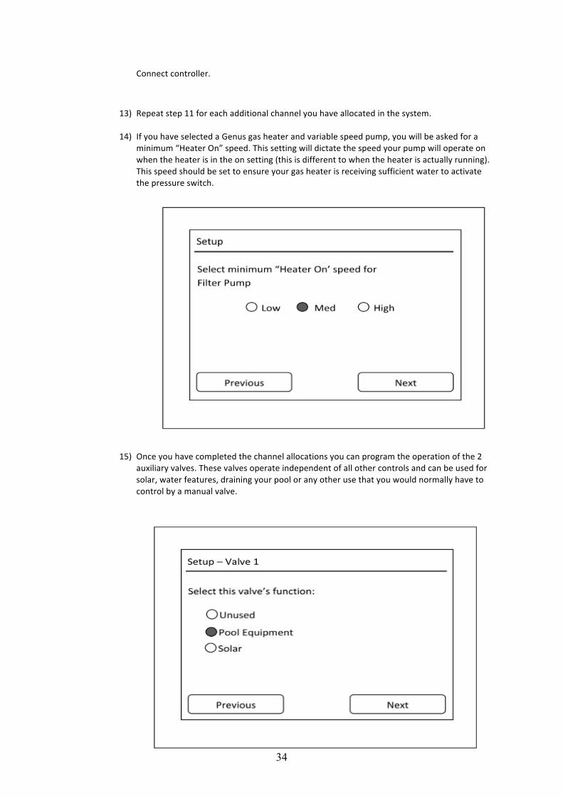
14) If you have selected a Genus gas heater and variable speed pump, you will be asked for a
minimum “Heater On” speed. This setting will dictate the speed your pump will operate on when the heater is in the on setting (this is different to when the heater is actually running). This speed should be set to ensure your gas heater is receiving sufficient water to activate the pressure switch.
15) Once you have completed the channel allocations you can program the operation of the 2 auxiliary valves. These valves operate independent of all other controls and can be used for solar, water features, draining your pool or any other use that you would normally have to control by a manual valve.
35
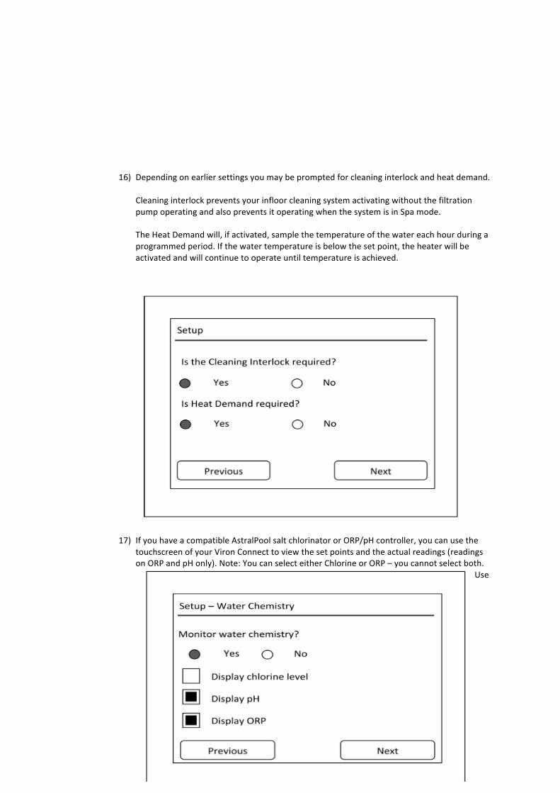
16) Depending on earlier settings you may be prompted for cleaning interlock and heat demand.
Cleaning interlock prevents your infloor cleaning system activating without the filtration pump operating and also prevents it operating when the system is in Spa mode. The Heat Demand will, if activated, sample the temperature of the water each hour during a programmed period. If the water temperature is below the set point, the heater will be activated and will continue to operate until temperature is achieved.
17) If you have a compatible AstralPool salt chlorinator or ORP/pH controller, you can use the touchscreen of your Viron Connect to view the set points and the actual readings (readings on ORP and pH only). Note: You can select either Chlorine or ORP – you cannot select both.
Use
36
Chlorine setting for salt chlorinators and ORP for liquid dosing systems.
18) A final summary screen will show the current settings for the controller. If correct, select Exit, otherwise select Change and repeat above process.
Section 8. Wireless Configuration / Setup
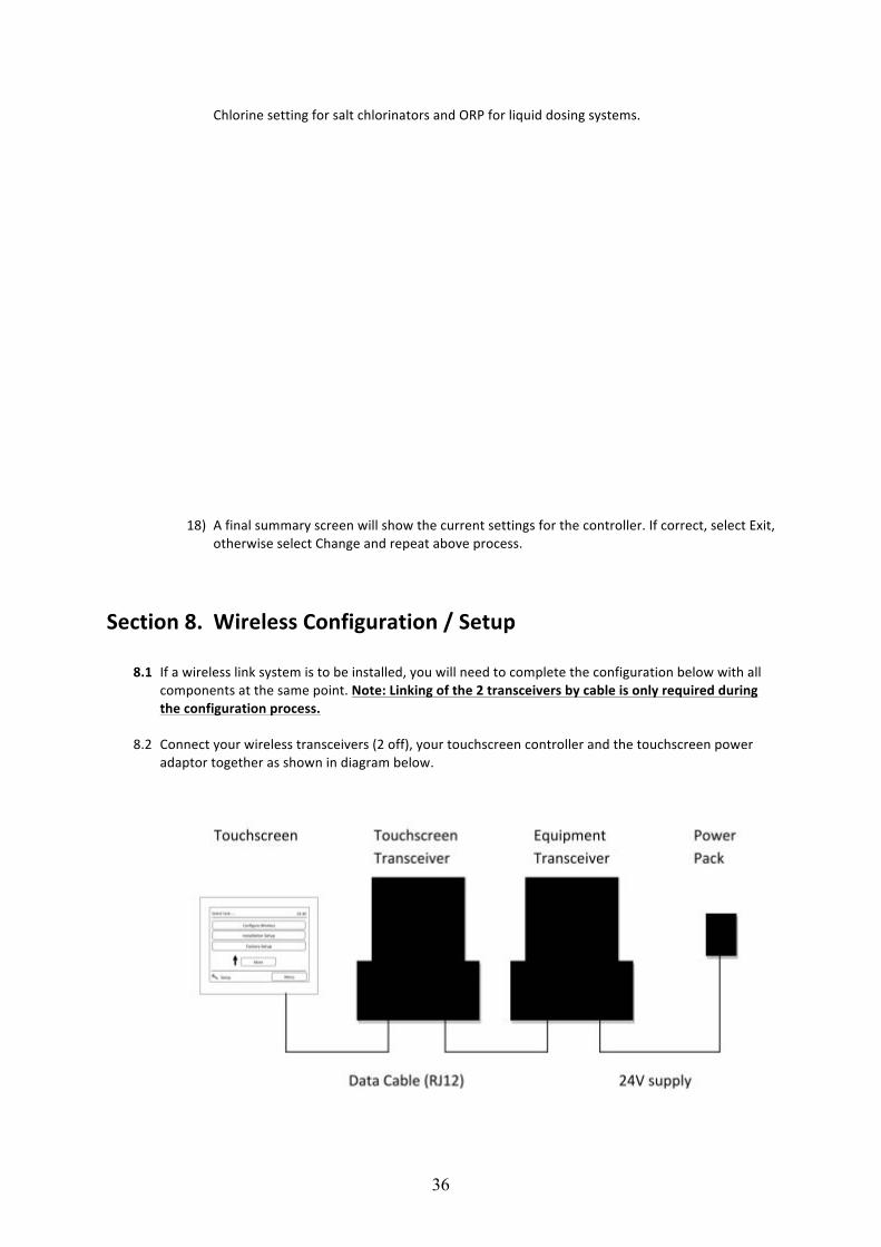
8.1 If a wireless link system is to be installed, you will need to complete the configuration below with all components at the same point. Note: Linking of the 2 transceivers by cable is only required during the configuration process.
8.2 Connect your wireless transceivers (2 off), your touchscreen controller and the touchscreen power
adaptor together as shown in diagram below.
37
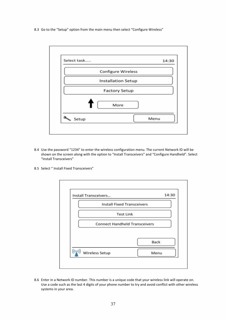
8.3 Go to the “Setup” option from the main menu then select “Configure Wireless”
8.4 Use the password “1234” to enter the wireless configuration menu. The current Network ID will be shown on the screen along with the option to “Install Transceivers” and “Configure Handheld”. Select “Install Transceivers”
8.5 Select “ Install Fixed Transceivers”
8.6 Enter in a Network ID number. This number is a unique code that your wireless link will operate on.
Use a code such as the last 4 digits of your phone number to try and avoid conflict with other wireless systems in your area.
38
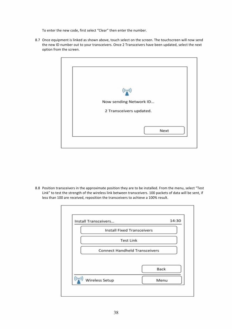
To enter the new code, first select “Clear” then enter the number.
8.7 Once equipment is linked as shown above, touch select on the screen. The touchscreen will now send the new ID number out to your transceivers. Once 2 Transceivers have been updated, select the next option from the screen.
8.8 Position transceivers in the approximate position they are to be installed. From the menu, select “Test Link” to test the strength of the wireless link between transceivers. 100 packets of data will be sent, if less than 100 are received, reposition the transceivers to achieve a 100% result.
39
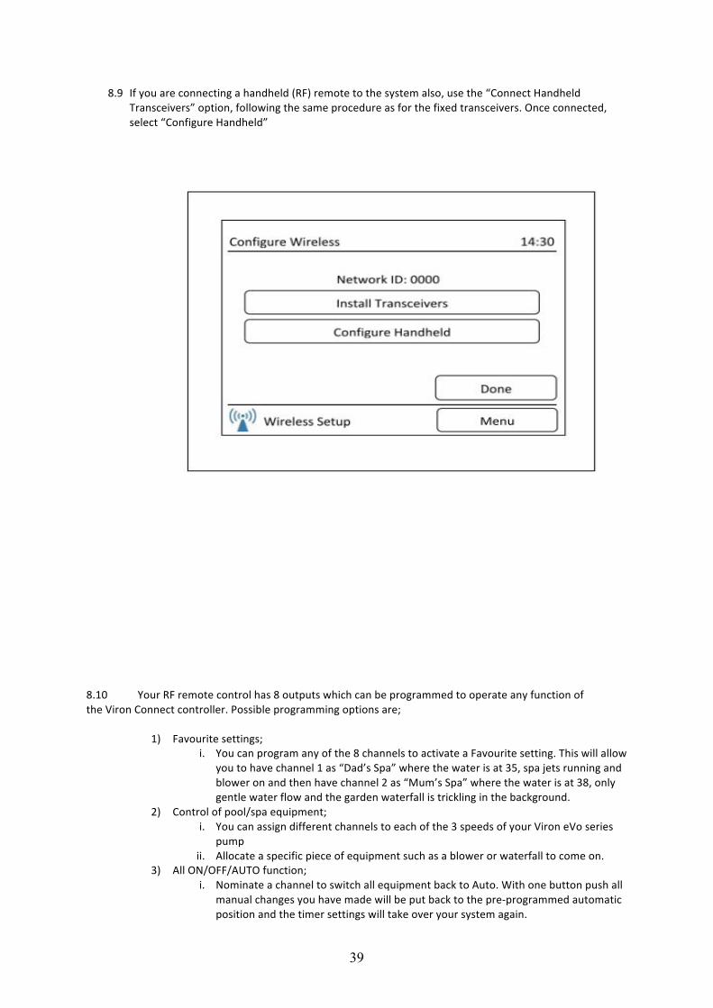
8.9 If you are connecting a handheld (RF) remote to the system also, use the “Connect Handheld Transceivers” option, following the same procedure as for the fixed transceivers. Once connected, select “Configure Handheld”
8.10 Your RF remote control has 8 outputs which can be programmed to operate any function of the Viron Connect controller. Possible programming options are;
1) Favourite settings; i. You can program any of the 8 channels to activate a Favourite setting. This will allow
you to have channel 1 as “Dad’s Spa” where the water is at 35, spa jets running and blower on and then have channel 2 as “Mum’s Spa” where the water is at 38, only gentle water flow and the garden waterfall is trickling in the background.
2) Control of pool/spa equipment; i. You can assign different channels to each of the 3 speeds of your Viron eVo series
pump ii. Allocate a specific piece of equipment such as a blower or waterfall to come on.
3) All ON/OFF/AUTO function; i. Nominate a channel to switch all equipment back to Auto. With one button push all
manual changes you have made will be put back to the pre-‐programmed automatic position and the timer settings will take over your system again.

40
4) Auxillary valve control; i. Turn your auxillary valves on/off or Auto
5) Lighting control; i. With a Delta lighting system installed, you can use your remote to toggle between
on and off or cycle between colours. ii. With any brand on lighting you can program lights on or assign lights to a favourite
setting 6) Heater control;
i. Toggle between On/Off on your heater
41
Section 9. External Heater Control (non-‐Genus)
9.1 If a non AstralPool heater is installed or a non Genus compliant heater (such as AstralPool heat pumps), the Viron Connect system can be configured to operate and control the heater from the touchscreen. If you have a AstralPool compliant gas heater installed, do not proceed with the following steps.
9.2 One channel of the Viron Connect controller must be allocated to control the On/Off
function of the heater. This can be any of channels 1 though 8.
9.3 To operate this feature, you must purchase a Viron Connect Temperature Sensor Kit. This can be purchased through any AstralPool dealer.
9.4 To install and operate an external heater;
i. Proceed through Touchscreen installation setup (Section 7 of this manual) and at
point 8, select No to Genus heater and Yes to use relay board for temperature sensing.
ii. Continue through setup until you are asked to set up the channel you are using for controlling the heater. For the channel function, select “Heater Controlled Power”
iii. Continue through remaining installation setup iv. The temperature sensor for the controller must be installed in the system plumbing
prior to the heater. The sensor kit is supplied with a 50mm PVC coupling to allow easy installation. The sensor probe must be plugged into the Viron Connect controller in the low voltage area. Note: If the solar feature of the Viron Connect system is being used, you cannot operate the external heater function. Please contact AstralPool for further advise if this situation arises.
v. For heaters supplied with a 10A cable, plug the appliance into the corresponding channel of the Viron Connect (channel that was nominated “Heater Controlled Power”). For appliances rated in excess of 10A (such as heat pumps), an electrician will be required to configure a relay/contactor setup to allow correct operation.
vi. Set the temperature on the heater thermostat to its maximum setting. Once configured the Viron Connect will control temperature making the thermostat on the heater redundant.
vii. On the Viron Connect touchscreen, select the “Heating” icon from the main menu. You can now select heater On or Off and adjust the temperature up and down. Once temperature is achieved, the Connect controller will cut power to the heater to prevent any further rise in temperature.
Section 10. Standard Solar control – operating a motorized valve
10.1 During Installation if select Basic Solar then ithe Connect 10 will ask if the Filter pump is required to run when the solar is on. If you want to use valves to divert water to the solar collector (instead of a separate pump) you need to answer Yes to this.
10.2 Later in the set up menus you are asked what function you wish to assign to the motorized valves: "Nothing, Pool Equipment or Solar". Select solar for one of the valves will map that valve to the solar controller.
42
10.3 If the filter pump isn't running and the solar calls for heat, the filter pump will start and the motorized valve will turn to divert water to the solar collector.
10.4 If the filter pump is already running just the valve will turn.
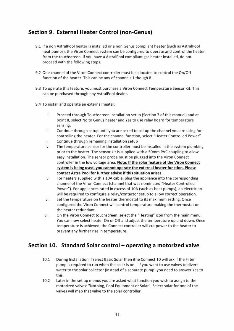
Section 11. Touch Screen Installation Instructions Plasterboard Recessed Insallation
43
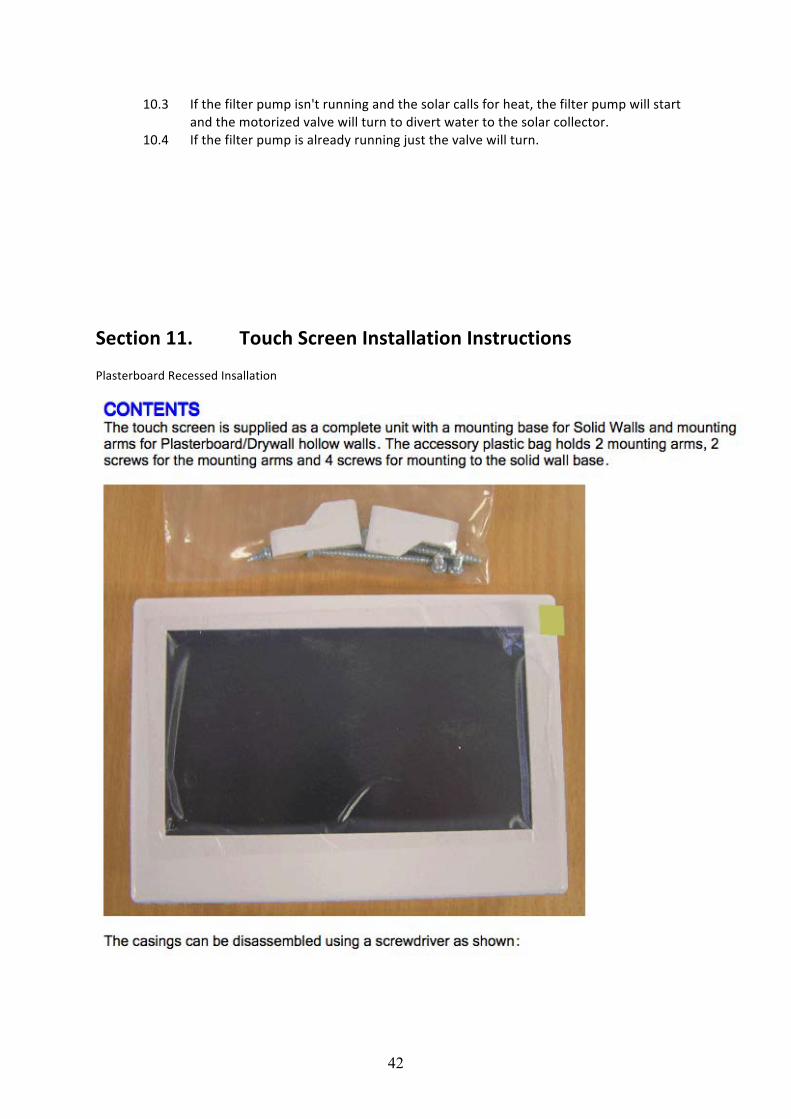
Section 11. Touch Screen Installation Instructions cont..
44
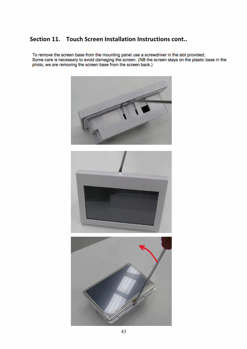
Section 11. Touch Screen Installation Instructions cont..
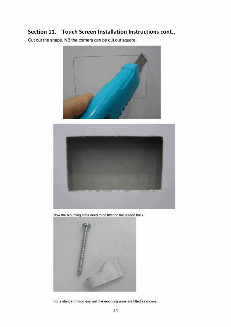
45
Section 11. Touch Screen Installation Instructions cont..
46
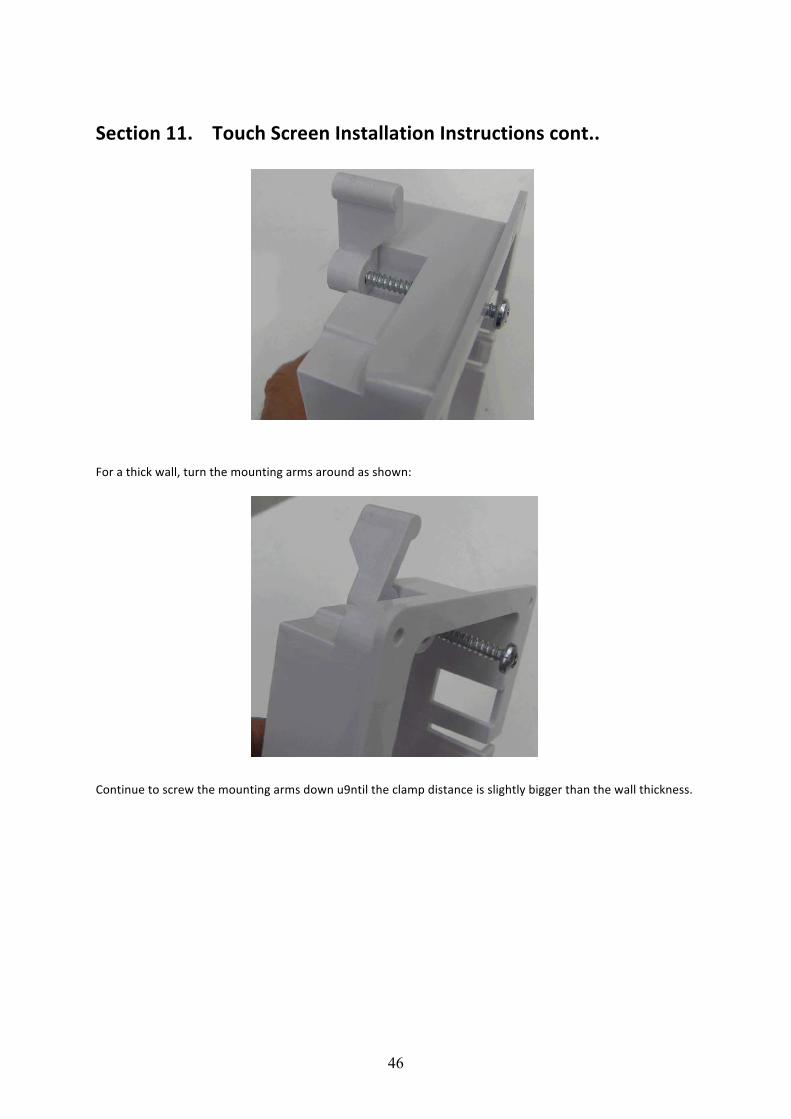
Section 11. Touch Screen Installation Instructions cont.. For a thick wall, turn the mounting arms around as shown:
Continue to screw the mounting arms down u9ntil the clamp distance is slightly bigger than the wall thickness.
47
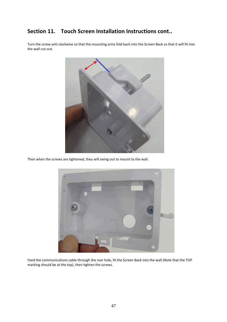
Section 11. Touch Screen Installation Instructions cont.. Turn the screw anti clockwise so that the mounting arms fold back into the Screen Back so that it will fit into the wall cut-‐out.
Then when the screws are tightened, they will swing out to mount to the wall.
Feed the communications cable through the rear hole, fit the Screen Back into the wall (Note that the TOP marking should be at the top), then tighten the screws.
48
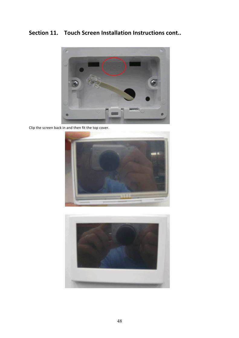
Section 11. Touch Screen Installation Instructions cont.. Clip the screen back in and then fit the top cover.
49
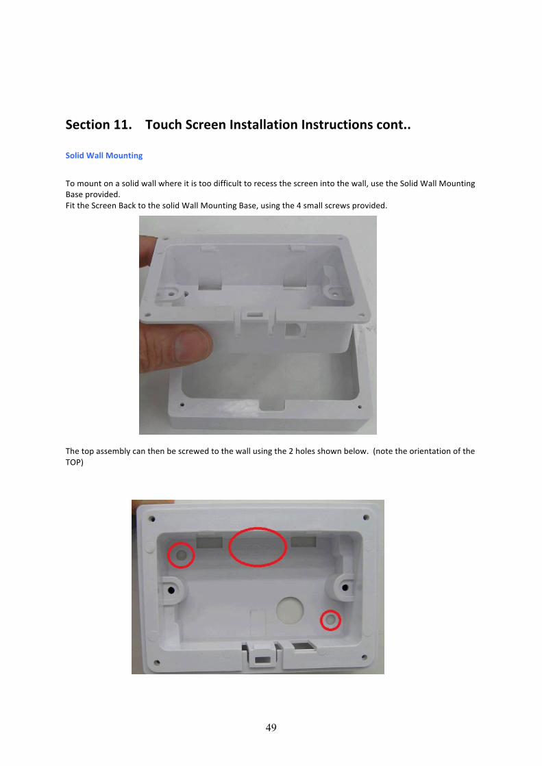
Section 11. Touch Screen Installation Instructions cont.. Solid Wall Mounting
To mount on a solid wall where it is too difficult to recess the screen into the wall, use the Solid Wall Mounting Base provided. Fit the Screen Back to the solid Wall Mounting Base, using the 4 small screws provided.
The top assembly can then be screwed to the wall using the 2 holes shown below. (note the orientation of the TOP)
50
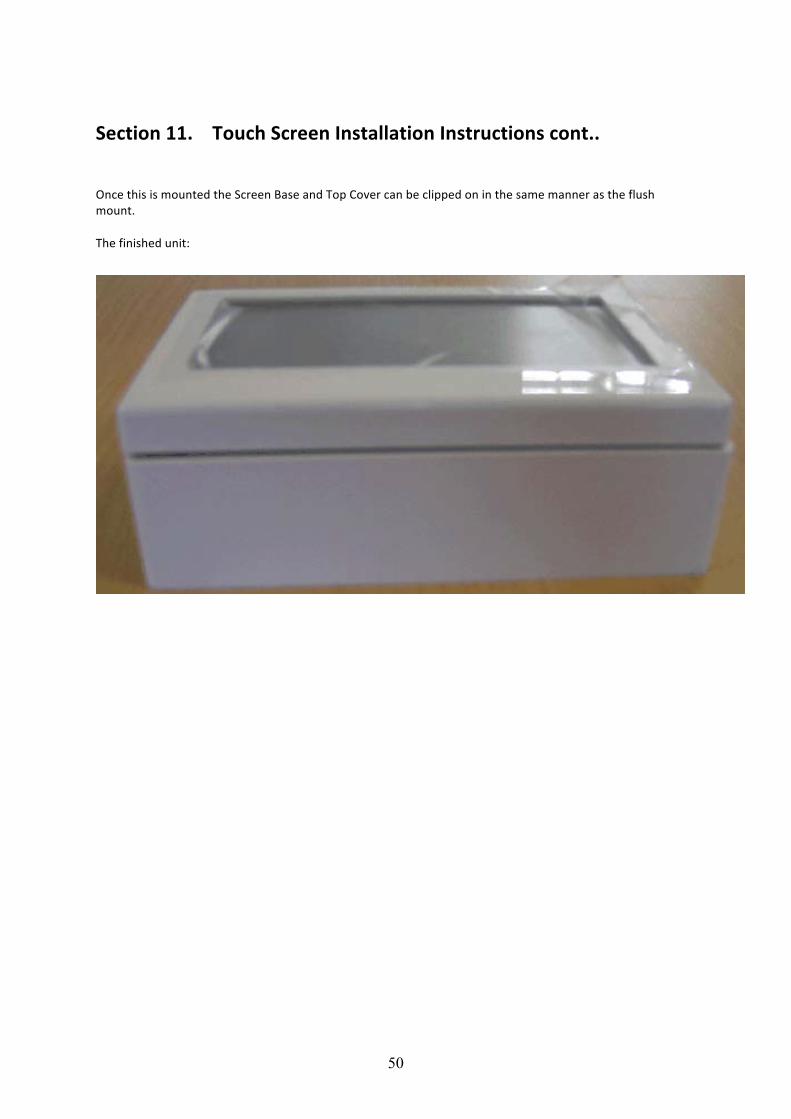
Section 11. Touch Screen Installation Instructions cont.. Once this is mounted the Screen Base and Top Cover can be clipped on in the same manner as the flush mount. The finished unit:
51
Section 12. Custom Switching (from external source)
10.1 The Viron Connect controller has the ability to accept two external switching inputs that allow for the operation of Favourite settings. The switching is controlled through a momentary pulse signal which will turn the selected Favourite on. A repeat pulse will re-‐confirm the favourite is to be on, it does not turn the favourite off. To turn the active favourite off and return to normal pre-‐programmed settings, the “All Auto” function must be selected from the Home menu.
10.2 For most installations using this feature the set up will be;
CUSTOM SWITCH 1 -‐ This will be programmed as one of the owners favourites CUSTOM SWITCH 2 -‐ This will be programmed as ALL AUTO
You cannot use CBUS to operate all features of the Connect 10. Temperature control, timers etc must still be operated through the touchscreen. You can only operate 2 selected functions through CBUS, you cannot operate all 8 channels.
10.3 To connect to the custom switches;
i. A 2 wire cable (low voltage) needs to be run from the named terminals on the Viron Connect back to the external controller (CBus or other home automation system)
ii. The switching terminals require a momentary pulse of an open/close contact. Note: the external controller must not supply any voltage back to the Viron Connect.
iii. In the Touchscreen installation setup (Section 7) when prompted select Yes to activate the use of external custom switches.
52
Section 13. Service Mode Operation
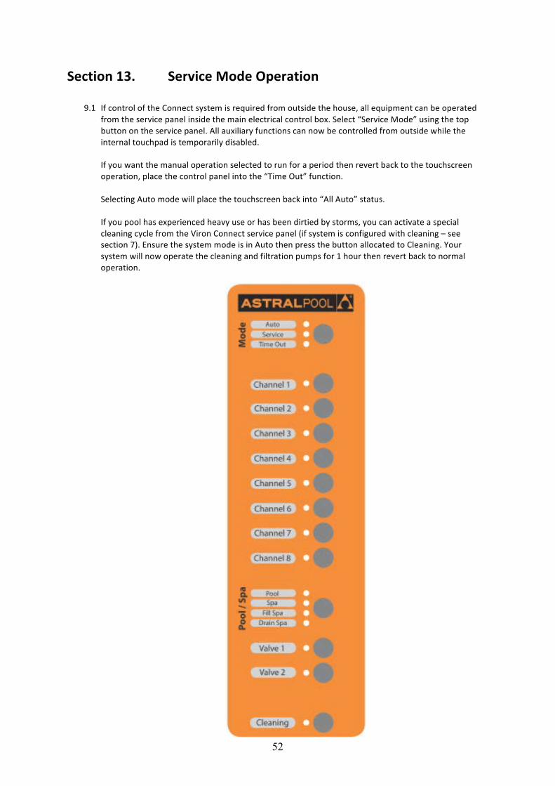
9.1 If control of the Connect system is required from outside the house, all equipment can be operated from the service panel inside the main electrical control box. Select “Service Mode” using the top button on the service panel. All auxiliary functions can now be controlled from outside while the internal touchpad is temporarily disabled.
If you want the manual operation selected to run for a period then revert back to the touchscreen operation, place the control panel into the “Time Out” function. Selecting Auto mode will place the touchscreen back into “All Auto” status. If you pool has experienced heavy use or has been dirtied by storms, you can activate a special cleaning cycle from the Viron Connect service panel (if system is configured with cleaning – see section 7). Ensure the system mode is in Auto then press the button allocated to Cleaning. Your system will now operate the cleaning and filtration pumps for 1 hour then revert back to normal operation.
53
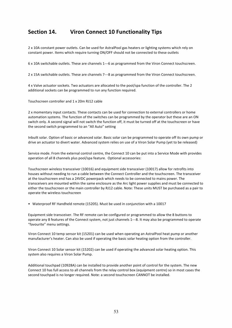
Section 14. Viron Connect 10 Functionality Tips 2 x 10A constant power outlets. Can be used for AstralPool gas heaters or lighting systems which rely on constant power. Items which require turning ON/OFF should not be connected to these outlets
6 x 10A switchable outlets. These are channels 1-‐-‐-‐6 as programmed from the Viron Connect touchscreen.
2 x 15A switchable outlets. These are channels 7-‐-‐-‐8 as programmed from the Viron Connect touchscreen.
4 x Valve actuator sockets. Two actuators are allocated to the pool/spa function of the controller. The 2 additional sockets can be programmed to run any function required.
Touchscreen controller and 1 x 20m RJ12 cable
2 x momentary input contacts. These contacts can be used for connection to external controllers or home automation systems. The function of the switches can be programmed by the operator but these are an ON switch only. A second signal will not switch the function off, it must be turned off at the touchscreen or have the second switch programmed to an “All Auto” setting
Inbuilt solar. Option of basic or advanced solar. Basic solar can be programmed to operate off its own pump or drive an actuator to divert water. Advanced system relies on use of a Viron Solar Pump (yet to be released)
Service mode. From the external control centre, the Connect 10 can be put into a Service Mode with provides operation of all 8 channels plus pool/spa feature. Optional accessories:
Touchscreen wireless transceiver (10016) and equipment side transceiver (10017) allow for retrofits into houses without needing to run a cable between the Connect Controller and the touchscreen. The transceiver at the touchscreen end has a 24VDC powerpack which needs to be connected to mains power. The transceivers are mounted within the same enclosure as the Arc light power supplies and must be connected to either the touchscreen or the main controller by RJ12 cable. Note: These units MUST be purchased as a pair to operate the wireless touchscreen
• Waterproof RF Handheld remote (15205). Must be used in conjunction with a 10017
Equipment side transceiver. The RF remote can be configured or programmed to allow the 8 buttons to operate any 8 features of the Connect system, not just channels 1-‐-‐-‐8. It may also be programmed to operate “favourite” menu settings.
Viron Connect 10 temp sensor kit (15201) can be used when operating an AstralPool heat pump or another manufacturer’s heater. Can also be used if operating the basic solar heating option from the controller.
Viron Connect 10 Solar sensor kit (15202) can be used if operating the advanced solar heating option. This system also requires a Viron Solar Pump.
Additional touchpad (10928A) can be installed to provide another point of control for the system. The new Connect 10 has full access to all channels from the relay control box (equipment centre) so in most cases the second touchpad is no longer required. Note: a second touchscreen CANNOT be installed.
54
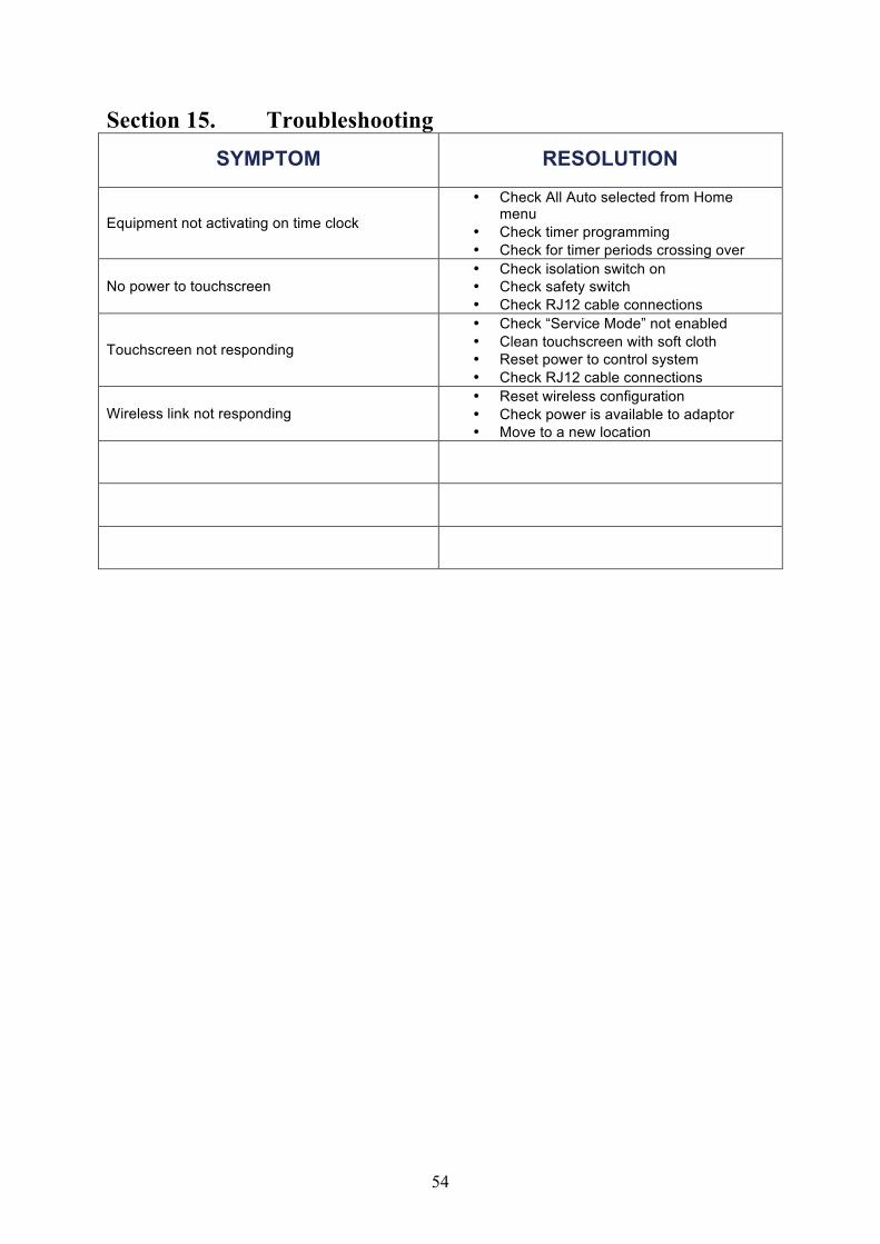
Section 15. Troubleshooting SYMPTOM RESOLUTION
Equipment not activating on time clock
• Check All Auto selected from Home menu
• Check timer programming • Check for timer periods crossing over
No power to touchscreen • Check isolation switch on • Check safety switch • Check RJ12 cable connections
Touchscreen not responding
• Check “Service Mode” not enabled • Clean touchscreen with soft cloth • Reset power to control system • Check RJ12 cable connections
Wireless link not responding • Reset wireless configuration • Check power is available to adaptor • Move to a new location
55
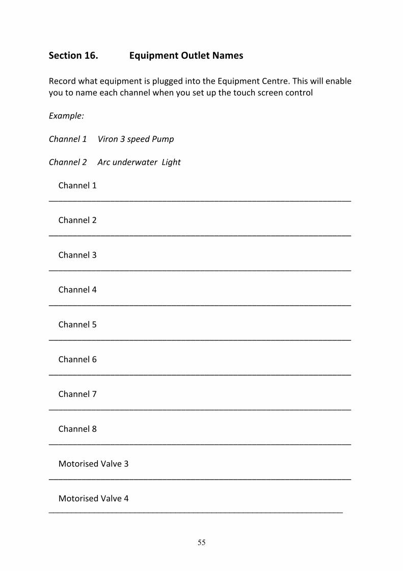
Section 16. Equipment Outlet Names Record what equipment is plugged into the Equipment Centre. This will enable you to name each channel when you set up the touch screen control Example: Channel 1 Viron 3 speed Pump Channel 2 Arc underwater Light
Channel 1 ________________________________________________________________
Channel 2
________________________________________________________________ Channel 3
________________________________________________________________ Channel 4
________________________________________________________________ Channel 5
________________________________________________________________ Channel 6
________________________________________________________________ Channel 7
________________________________________________________________ Channel 8
________________________________________________________________ Motorised Valve 3
________________________________________________________________ Motorised Valve 4
_________________________________________________________________

56
57
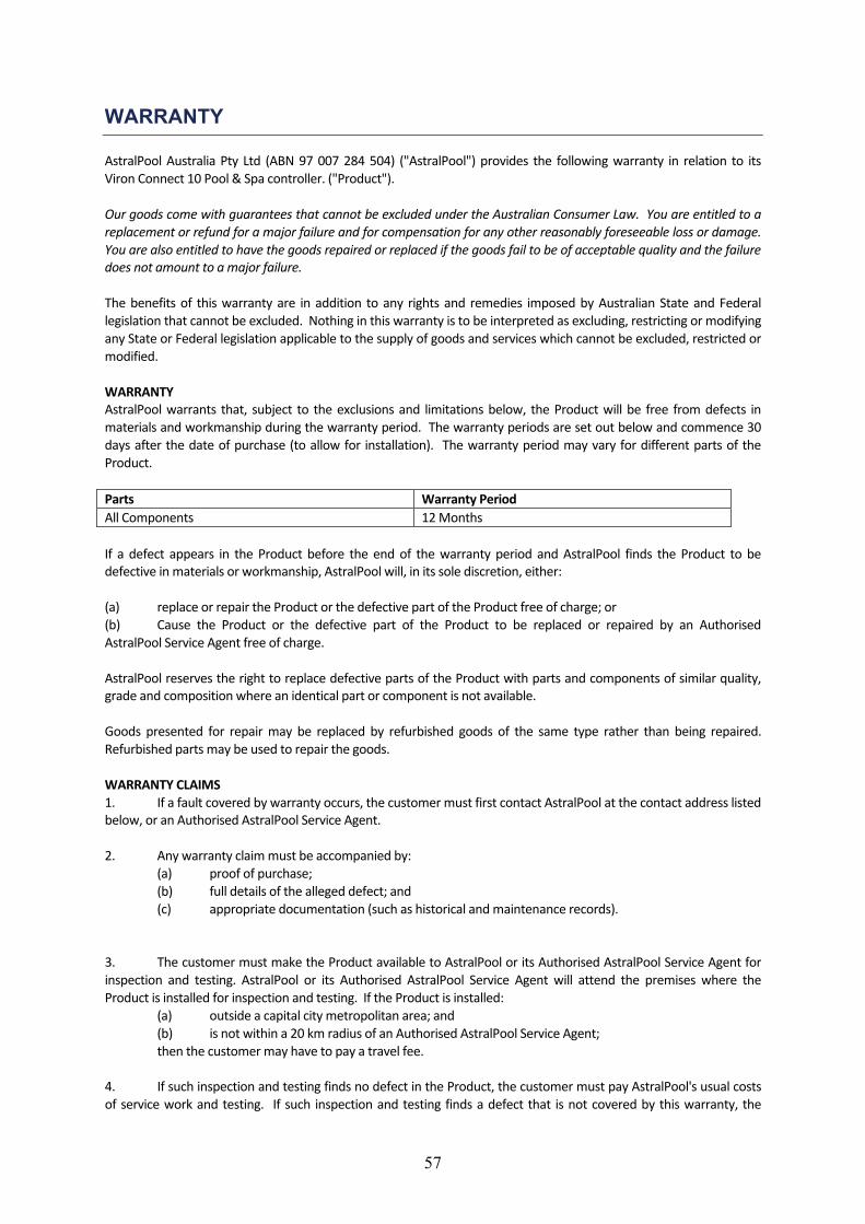
WARRANTY
AstralPool Australia Pty Ltd (ABN 97 007 284 504) ("AstralPool") provides the following warranty in relation to its Viron Connect 10 Pool & Spa controller. ("Product"). Our goods come with guarantees that cannot be excluded under the Australian Consumer Law. You are entitled to a replacement or refund for a major failure and for compensation for any other reasonably foreseeable loss or damage. You are also entitled to have the goods repaired or replaced if the goods fail to be of acceptable quality and the failure does not amount to a major failure. The benefits of this warranty are in addition to any rights and remedies imposed by Australian State and Federal legislation that cannot be excluded. Nothing in this warranty is to be interpreted as excluding, restricting or modifying any State or Federal legislation applicable to the supply of goods and services which cannot be excluded, restricted or modified. WARRANTY AstralPool warrants that, subject to the exclusions and limitations below, the Product will be free from defects in materials and workmanship during the warranty period. The warranty periods are set out below and commence 30 days after the date of purchase (to allow for installation). The warranty period may vary for different parts of the Product. Parts Warranty Period All Components 12 Months If a defect appears in the Product before the end of the warranty period and AstralPool finds the Product to be defective in materials or workmanship, AstralPool will, in its sole discretion, either: (a) replace or repair the Product or the defective part of the Product free of charge; or (b) Cause the Product or the defective part of the Product to be replaced or repaired by an Authorised AstralPool Service Agent free of charge. AstralPool reserves the right to replace defective parts of the Product with parts and components of similar quality, grade and composition where an identical part or component is not available. Goods presented for repair may be replaced by refurbished goods of the same type rather than being repaired. Refurbished parts may be used to repair the goods. WARRANTY CLAIMS 1. If a fault covered by warranty occurs, the customer must first contact AstralPool at the contact address listed below, or an Authorised AstralPool Service Agent. 2. Any warranty claim must be accompanied by: (a) proof of purchase; (b) full details of the alleged defect; and (c) appropriate documentation (such as historical and maintenance records). 3. The customer must make the Product available to AstralPool or its Authorised AstralPool Service Agent for inspection and testing. AstralPool or its Authorised AstralPool Service Agent will attend the premises where the Product is installed for inspection and testing. If the Product is installed: (a) outside a capital city metropolitan area; and (b) is not within a 20 km radius of an Authorised AstralPool Service Agent; then the customer may have to pay a travel fee. 4. If such inspection and testing finds no defect in the Product, the customer must pay AstralPool's usual costs of service work and testing. If such inspection and testing finds a defect that is not covered by this warranty, the
58
customer must pay AstralPool's usual costs of service work plus any parts and labour required to repair the Product, unless recoverable from AstralPool on the failure of any statutory guarantee under the ACL. Exclusions The warranty will not apply where: (a) the customer is in breach of the Terms and Conditions of Sale; (b) the Product was used for a purpose other than one it was intended for; (c) the Product was repaired, modified or altered by any person other than AstralPool; (d) the Product has not been installed, maintained and/or operated in complete compliance with the installation and operating instructions and any instructions by AstralPool; (e) the Product has been subject to accident, negligence, alteration, abuse or misuse. The warranty does not extend to: a) normal wear and tear; b) weather and other environmental conditions including but not limited to storm, flood, and/or heat wave
damage; or c) service and maintenance items. Examples of exclusions include but are not limited to: • Incorrect installation • External power spikes / surges Commercial Installations On commercial installations, such as health clubs, motels/hotels and hydrotherapy facilities, the warranty is limited to parts and in field labour (within capital city metropolitan areas or 20 km radius of Authorised AstralPool Service Agents) for a period of 12 months from the date of purchase plus 30 days to allow for installation. LIMITATIONS AstralPool makes no express warranties or representations other than set out in this warranty. The repair or replacement of the Product or part of the Product is the absolute limit of AstralPool's liability under this express warranty.
59
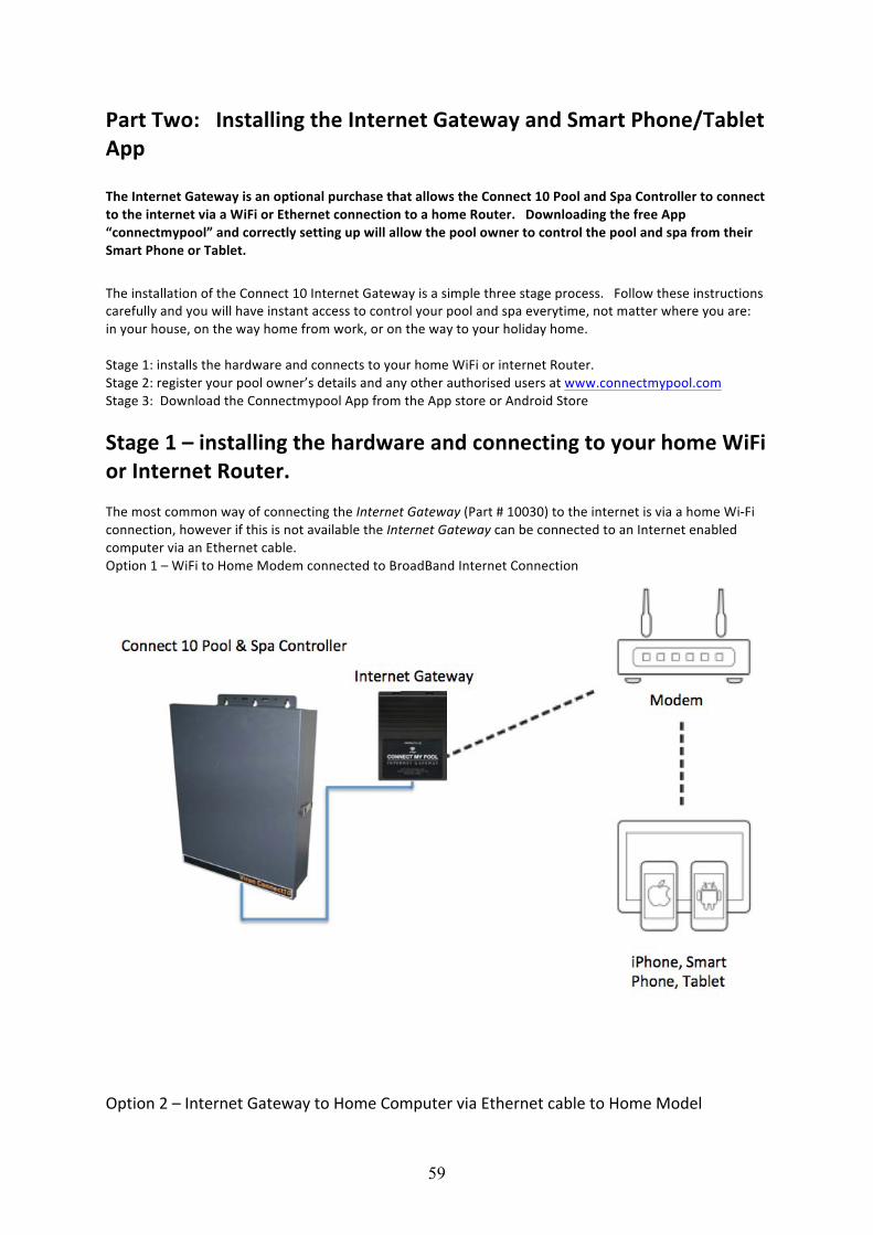
Part Two: Installing the Internet Gateway and Smart Phone/Tablet App The Internet Gateway is an optional purchase that allows the Connect 10 Pool and Spa Controller to connect to the internet via a WiFi or Ethernet connection to a home Router. Downloading the free App “connectmypool” and correctly setting up will allow the pool owner to control the pool and spa from their Smart Phone or Tablet.
The installation of the Connect 10 Internet Gateway is a simple three stage process. Follow these instructions carefully and you will have instant access to control your pool and spa everytime, not matter where you are: in your house, on the way home from work, or on the way to your holiday home. Stage 1: installs the hardware and connects to your home WiFi or internet Router. Stage 2: register your pool owner’s details and any other authorised users at www.connectmypool.com Stage 3: Download the Connectmypool App from the App store or Android Store
Stage 1 – installing the hardware and connecting to your home WiFi or Internet Router. The most common way of connecting the Internet Gateway (Part # 10030) to the internet is via a home Wi-‐Fi connection, however if this is not available the Internet Gateway can be connected to an Internet enabled computer via an Ethernet cable. Option 1 – WiFi to Home Modem connected to BroadBand Internet Connection
Option 2 – Internet Gateway to Home Computer via Ethernet cable to Home Model
60
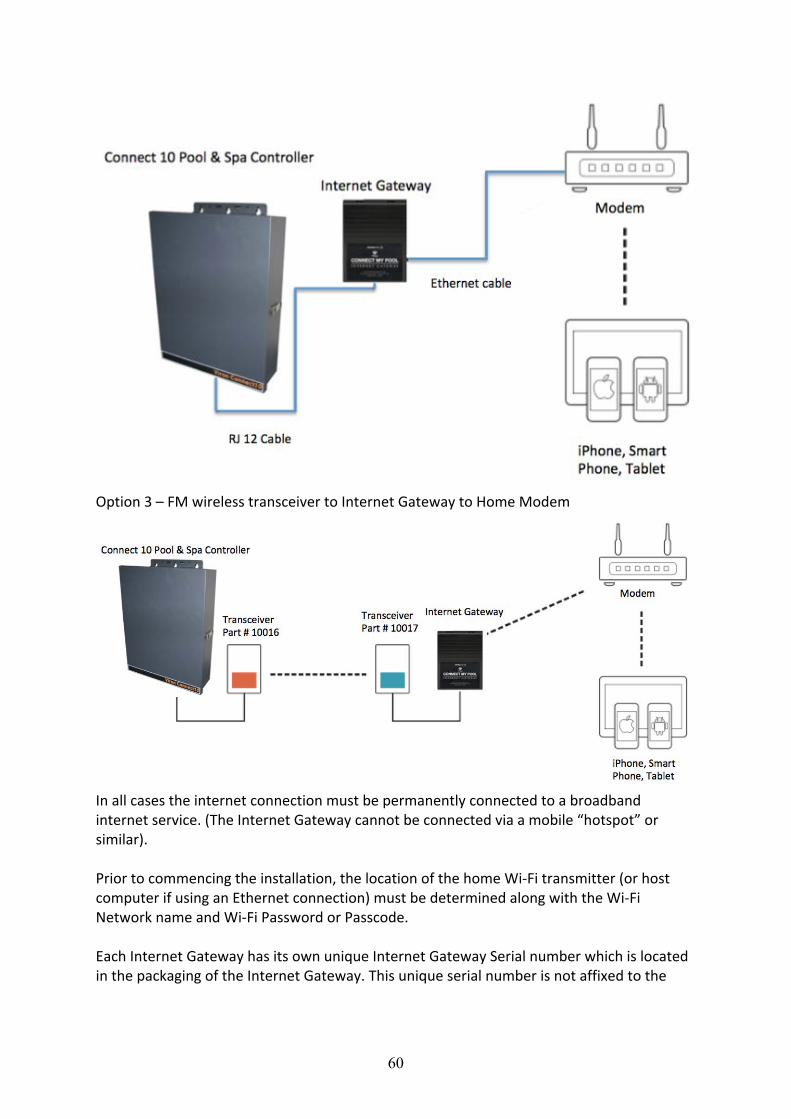
Option 3 – FM wireless transceiver to Internet Gateway to Home Modem
In all cases the internet connection must be permanently connected to a broadband internet service. (The Internet Gateway cannot be connected via a mobile “hotspot” or similar). Prior to commencing the installation, the location of the home Wi-‐Fi transmitter (or host computer if using an Ethernet connection) must be determined along with the Wi-‐Fi Network name and Wi-‐Fi Password or Passcode. Each Internet Gateway has its own unique Internet Gateway Serial number which is located in the packaging of the Internet Gateway. This unique serial number is not affixed to the
61
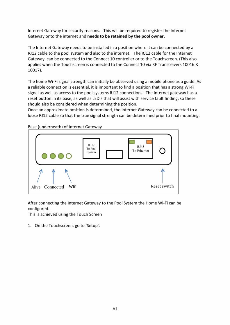
Internet Gateway for security reasons. This will be required to register the Internet Gateway onto the internet and needs to be retained by the pool owner. The Internet Gateway needs to be installed in a position where it can be connected by a RJ12 cable to the pool system and also to the internet. The RJ12 cable for the Internet Gateway can be connected to the Connect 10 controller or to the Touchscreen. (This also applies when the Touchscreen is connected to the Connect 10 via RF Transceivers 10016 & 10017). The home Wi-‐Fi signal strength can initially be observed using a mobile phone as a guide. As a reliable connection is essential, it is important to find a position that has a strong Wi-‐Fi signal as well as access to the pool systems RJ12 connections. The Internet gateway has a reset button in its base, as well as LED’s that will assist with service fault finding, so these should also be considered when determining the position. Once an approximate position is determined, the Internet Gateway can be connected to a loose RJ12 cable so that the true signal strength can be determined prior to final mounting. Base (underneath) of Internet Gateway
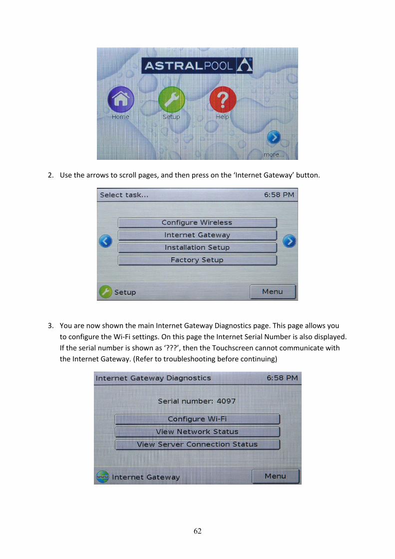
After connecting the Internet Gateway to the Pool System the Home Wi-‐Fi can be configured. This is achieved using the Touch Screen 1. On the Touchscreen, go to ‘Setup’.
Connected Wifi Alive Reset switch
RJ12 To Pool System
RJ45 To Ethernet
62
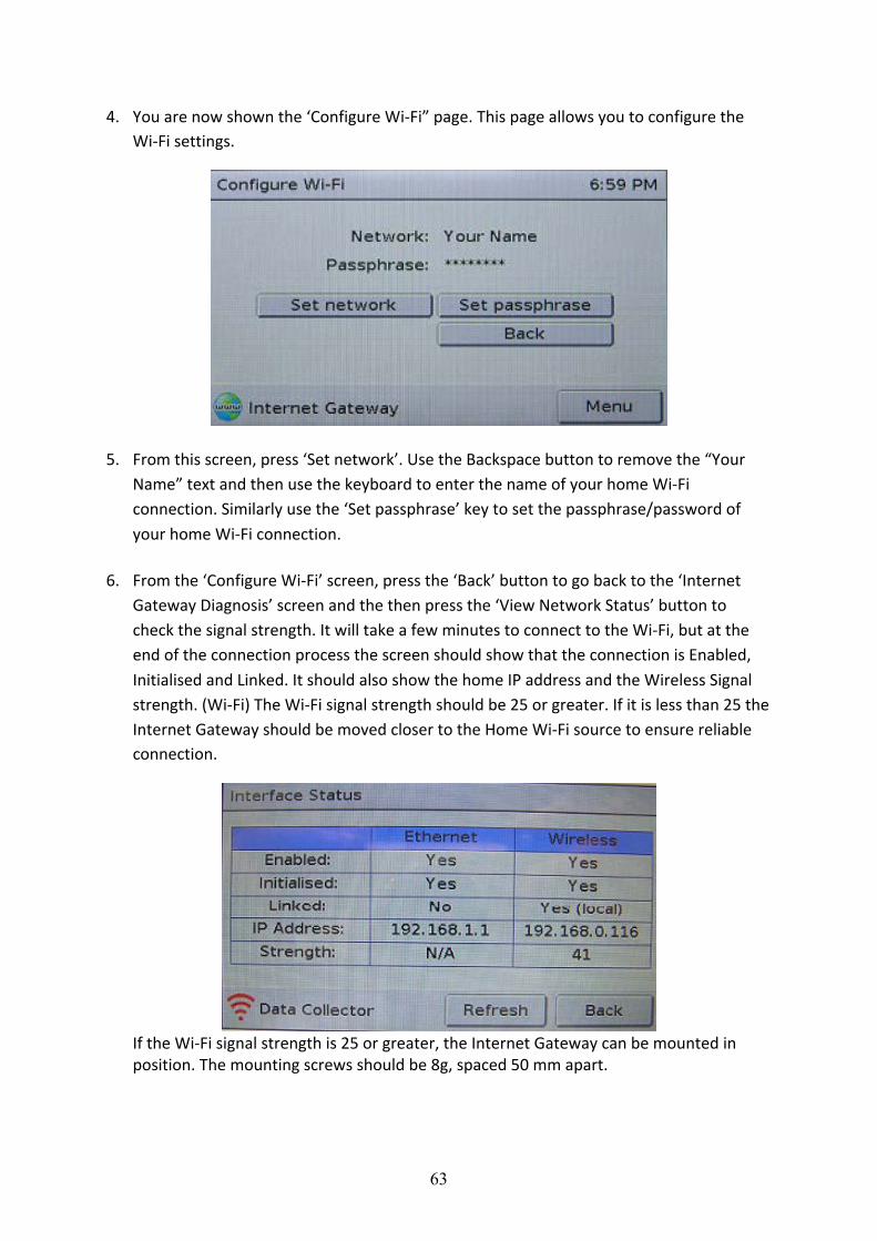
2. Use the arrows to scroll pages, and then press on the ‘Internet Gateway’ button.
3. You are now shown the main Internet Gateway Diagnostics page. This page allows you to configure the Wi-‐Fi settings. On this page the Internet Serial Number is also displayed. If the serial number is shown as ‘???’, then the Touchscreen cannot communicate with the Internet Gateway. (Refer to troubleshooting before continuing)
63
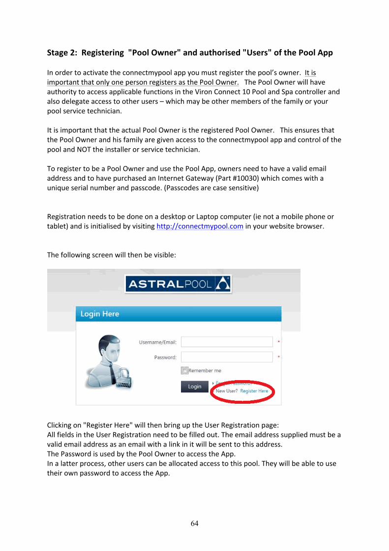
4. You are now shown the ‘Configure Wi-‐Fi” page. This page allows you to configure the Wi-‐Fi settings.
5. From this screen, press ‘Set network’. Use the Backspace button to remove the “Your Name” text and then use the keyboard to enter the name of your home Wi-‐Fi connection. Similarly use the ‘Set passphrase’ key to set the passphrase/password of your home Wi-‐Fi connection.
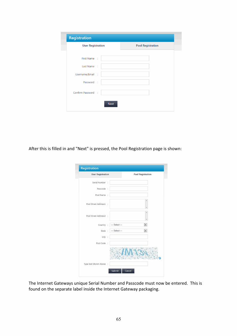
6. From the ‘Configure Wi-‐Fi’ screen, press the ‘Back’ button to go back to the ‘Internet Gateway Diagnosis’ screen and the then press the ‘View Network Status’ button to check the signal strength. It will take a few minutes to connect to the Wi-‐Fi, but at the end of the connection process the screen should show that the connection is Enabled, Initialised and Linked. It should also show the home IP address and the Wireless Signal strength. (Wi-‐Fi) The Wi-‐Fi signal strength should be 25 or greater. If it is less than 25 the Internet Gateway should be moved closer to the Home Wi-‐Fi source to ensure reliable connection.
If the Wi-‐Fi signal strength is 25 or greater, the Internet Gateway can be mounted in position. The mounting screws should be 8g, spaced 50 mm apart.
64
Stage 2: Registering "Pool Owner" and authorised "Users" of the Pool App In order to activate the connectmypool app you must register the pool’s owner. It is important that only one person registers as the Pool Owner. The Pool Owner will have authority to access applicable functions in the Viron Connect 10 Pool and Spa controller and also delegate access to other users – which may be other members of the family or your pool service technician. It is important that the actual Pool Owner is the registered Pool Owner. This ensures that the Pool Owner and his family are given access to the connectmypool app and control of the pool and NOT the installer or service technician. To register to be a Pool Owner and use the Pool App, owners need to have a valid email address and to have purchased an Internet Gateway (Part #10030) which comes with a unique serial number and passcode. (Passcodes are case sensitive) Registration needs to be done on a desktop or Laptop computer (ie not a mobile phone or tablet) and is initialised by visiting http://connectmypool.com in your website browser. The following screen will then be visible:
Clicking on "Register Here" will then bring up the User Registration page: All fields in the User Registration need to be filled out. The email address supplied must be a valid email address as an email with a link in it will be sent to this address. The Password is used by the Pool Owner to access the App. In a latter process, other users can be allocated access to this pool. They will be able to use their own password to access the App.
65
After this is filled in and "Next" is pressed, the Pool Registration page is shown: The Internet Gateways unique Serial Number and Passcode must now be entered. This is found on the separate label inside the Internet Gateway packaging.

66
The Pool Name that is entered on this page will be displayed on the App. If you plan to be able to log into more than one pool, then the name should describe which pool you are wanting to control. e.g. For this registration you may name the pool "Jones Home" and for a second Pool Registration it may be named "Jones Beach" . (Once your first Pool has been registered, the second pool can be entered later by logging on (using a desktop computer) through the "Settings" tab The Pool Street address and Post Code is used to identify the Pool Location and provide weather information for the area around the pool. After pressing the "Submit" button above, an email should be delivered to your Email Address. This email will contain a link that you need to press to complete the registration process. NB Some providers may interpret this email as Junk. If you don't receive an email within a few minutes please check your Junk email folder. After completing registration, it is necessary to log out. Wait 10 minutes and log back in with the user name/email and password you created. The system should now have configured itself and you will have access to the programming that has already been completed on your Connect 10 touch screen. After the system has configured itself you can proceed to add more users etc to your pool if required. This can allow all your family members with a Smart Phone or Tablet to also access the pool and control remotely. To let additional people access your pool controller press "SETTINGS" then "User List" then "Add User"
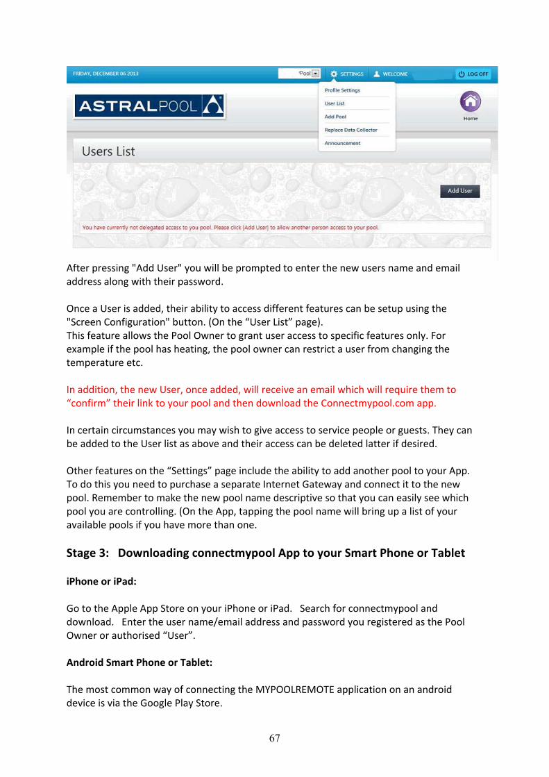
67
After pressing "Add User" you will be prompted to enter the new users name and email address along with their password. Once a User is added, their ability to access different features can be setup using the "Screen Configuration" button. (On the “User List” page). This feature allows the Pool Owner to grant user access to specific features only. For example if the pool has heating, the pool owner can restrict a user from changing the temperature etc. In addition, the new User, once added, will receive an email which will require them to “confirm” their link to your pool and then download the Connectmypool.com app. In certain circumstances you may wish to give access to service people or guests. They can be added to the User list as above and their access can be deleted latter if desired. Other features on the “Settings” page include the ability to add another pool to your App. To do this you need to purchase a separate Internet Gateway and connect it to the new pool. Remember to make the new pool name descriptive so that you can easily see which pool you are controlling. (On the App, tapping the pool name will bring up a list of your available pools if you have more than one. Stage 3: Downloading connectmypool App to your Smart Phone or Tablet iPhone or iPad: Go to the Apple App Store on your iPhone or iPad. Search for connectmypool and download. Enter the user name/email address and password you registered as the Pool Owner or authorised “User”. Android Smart Phone or Tablet: The most common way of connecting the MYPOOLREMOTE application on an android device is via the Google Play Store.
68
Go to the Google Play store on your device. Search for connectmypool and download the App. Enter the user name/email address and password that you registered as the Pool Owner or authorized Pool User.
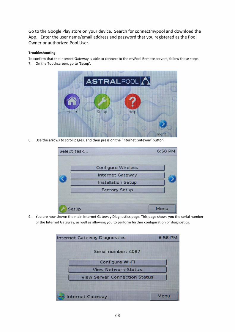
Troubleshooting To confirm that the Internet Gateway is able to connect to the myPool Remote servers, follow these steps. 7. On the Touchscreen, go to ‘Setup’.
8. Use the arrows to scroll pages, and then press on the ‘Internet Gateway’ button.
9. You are now shown the main Internet Gateway Diagnostics page. This page shows you the serial number
of the Internet Gateway, as well as allowing you to perform further configuration or diagnostics.
69
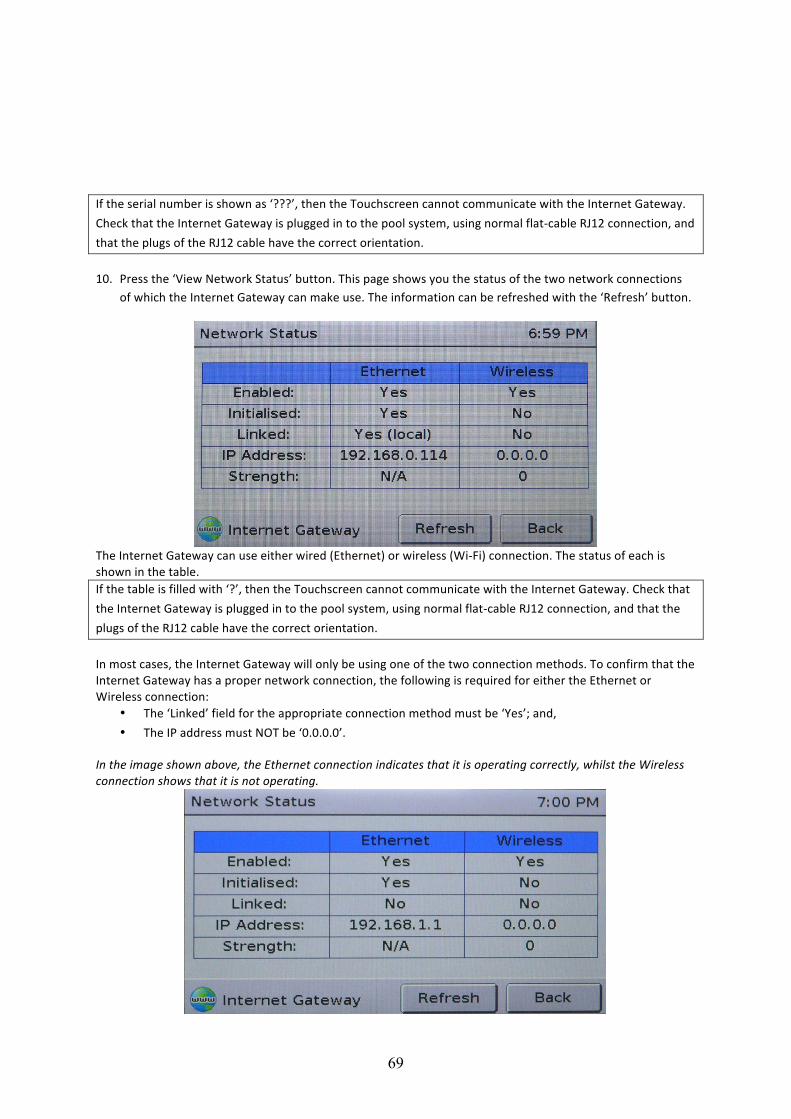
If the serial number is shown as ‘???’, then the Touchscreen cannot communicate with the Internet Gateway. Check that the Internet Gateway is plugged in to the pool system, using normal flat-‐cable RJ12 connection, and that the plugs of the RJ12 cable have the correct orientation.
10. Press the ‘View Network Status’ button. This page shows you the status of the two network connections
of which the Internet Gateway can make use. The information can be refreshed with the ‘Refresh’ button.
The Internet Gateway can use either wired (Ethernet) or wireless (Wi-‐Fi) connection. The status of each is shown in the table. If the table is filled with ‘?’, then the Touchscreen cannot communicate with the Internet Gateway. Check that the Internet Gateway is plugged in to the pool system, using normal flat-‐cable RJ12 connection, and that the plugs of the RJ12 cable have the correct orientation. In most cases, the Internet Gateway will only be using one of the two connection methods. To confirm that the Internet Gateway has a proper network connection, the following is required for either the Ethernet or Wireless connection:
• The ‘Linked’ field for the appropriate connection method must be ‘Yes’; and, • The IP address must NOT be ‘0.0.0.0’.
In the image shown above, the Ethernet connection indicates that it is operating correctly, whilst the Wireless connection shows that it is not operating.
70
In the image above, the Ethernet connection is no longer operating correctly, as the ‘Linked’ field shows ‘No’. Troubleshooting The Ethernet Connection ‘Initialised’ shows ‘No’
The Internet Gateway was unable to initialise the Ethernet connection. Cycle power to the Internet Gateway and wait 1 minute to allow for re-‐initialisation. If the problem persists, call AstralPool for support.
‘Linked’ shows ‘No’ Check that the Ethernet cable is correctly connected to both the Internet Gateway and the pool owner’s home network hub (router). Check the orange light beside the Internet Gateway’s Ethernet connection; if it is illuminated, the Ethernet connection is present and there must be an internal issue with the Internet Gateway. Try cycling power to the IG. If the problem persists, call AstralPool for support.
Troubleshooting The Wireless Connection ‘Initialised’ shows ‘No’
The Internet Gateway was unable to initialise the Wireless connection. Cycle power to the Internet Gateway and wait 1 minute to allow for re-‐initialisation. If the problem persists, call AstralPool for support.
‘Linked’ shows ‘No’ The Internet Gateway was unable to connect to the pool owner’s wireless network. Verify that the network name and passphrase have been correctly configured by re-‐entering them into the Touchscreen. Allow the Internet Gateway 30 seconds to attempt connection to the home network before proceeding. Cycle power to the Internet Gateway and wait 1 minute to allow for re-‐initialisation. If the problem persists, call AstralPool for support.
IP Address shows ‘0.0.0.0’ The most common cause is that the Internet Gateway is right on the fringe of wireless range. Try moving the Internet Gateway closer to the pool owner’s wireless router, then cycle power to the Internet Gateway to cause re-‐initialisation. Ideally, the strength should be shown as 25 or greater. If the problem persists, consider changing from Wireless to Ethernet connection types.
11. Return to the main Internet Gateway Diagnostics screen by pressing ‘Back’. 12. Press the ‘View Server Connection Status’ button. This page shows you that status of the connection
between the Internet Gateway and the myPool Remote server.
71
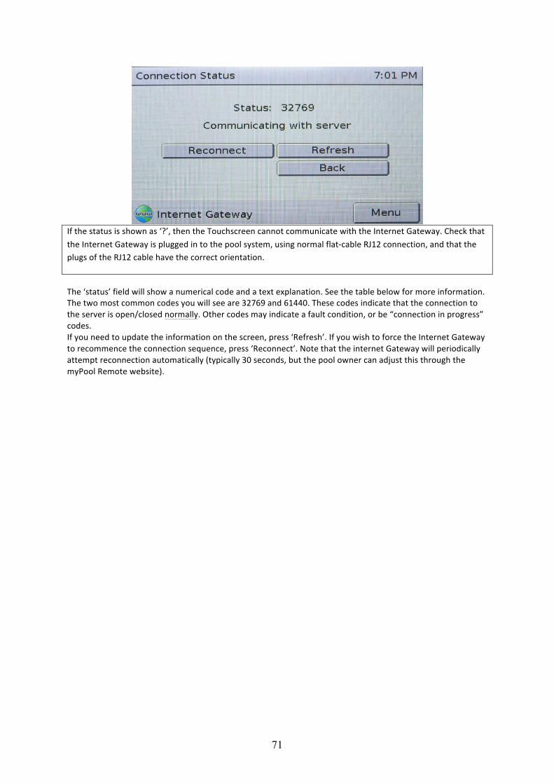
If the status is shown as ‘?’, then the Touchscreen cannot communicate with the Internet Gateway. Check that the Internet Gateway is plugged in to the pool system, using normal flat-‐cable RJ12 connection, and that the plugs of the RJ12 cable have the correct orientation.
The ‘status’ field will show a numerical code and a text explanation. See the table below for more information. The two most common codes you will see are 32769 and 61440. These codes indicate that the connection to the server is open/closed normally. Other codes may indicate a fault condition, or be “connection in progress” codes. If you need to update the information on the screen, press ‘Refresh’. If you wish to force the Internet Gateway to recommence the connection sequence, press ‘Reconnect’. Note that the internet Gateway will periodically attempt reconnection automatically (typically 30 seconds, but the pool owner can adjust this through the myPool Remote website).
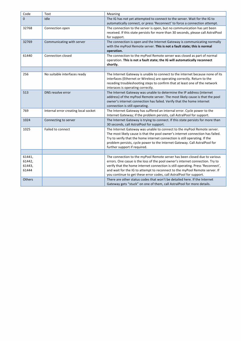
Code Text Meaning 0 Idle The IG has not yet attempted to connect to the server. Wait for the IG to
automatically connect, or press ‘Reconnect’ to force a connection attempt. 32768 Connection open The connection to the server is open, but no communication has yet been
received. If this state persists for more than 30 seconds, please call AstralPool for support.
32769 Communicating with server The connection is open and the Internet Gateway is communicating normally with the myPool Remote server. This is not a fault state; this is normal operation.
61440 Connection closed The connection to the myPool Remote server was closed as part of normal operation. This is not a fault state; the IG will automatically reconnect shortly.
256 No suitable interfaces ready The Internet Gateway is unable to connect to the internet because none of its
interfaces (Ethernet or Wireless) are operating correctly. Return to the receding troubleshooting steps to confirm that at least one of the network interaces is operating correctly.
513 DNS resolve error The Internet Gateway was unable to determine the IP address (internet address) of the myPool Remote server. The most likely cause is that the pool owner’s internet connection has failed. Verify that the home internet connection is still operating.
769 Internal error creating local socket The Internet Gateway has suffered an internal error. Cycle power to the Internet Gateway; if the problem persists, call AstralPool for support.
1024 Connecting to server The Internet Gateway is trying to connect. If this state persists for more than 30 seconds, call AstralPool for support.
1025 Failed to connect The Internet Gateway was unable to connect to the myPool Remote server. The most likely cause is that the pool owner’s internet connection has failed. Try to verify that the home internet connection is still operating. If the problem persists, cycle power to the Internet Gateway. Call AstralPool for further support if required.
61441, 61442, 61443, 61444
The connection to the myPool Remote server has been closed due to various errors. One casue is the loss of the pool owner’s internet connection. Try to verify that the home internet connection is still operating. Press ‘Reconnect’, and wait for the IG to attempt to reconnect to the myPool Remote server. If you continue to get these error codes, call AstralPool for support.
Others There are other status codes that won’t be detailed here. If the Internet Gateway gets “stuck” on one of them, call AstralPool for more details.
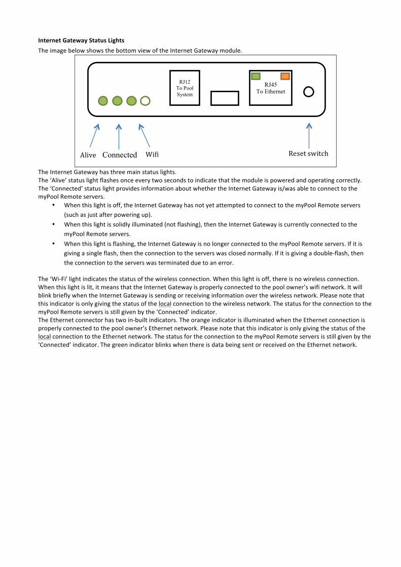
Internet Gateway Status Lights The image below shows the bottom view of the Internet Gateway module.
The Internet Gateway has three main status lights. The ‘Alive’ status light flashes once every two seconds to indicate that the module is powered and operating correctly. The ‘Connected’ status light provides information about whether the Internet Gateway is/was able to connect to the myPool Remote servers.
• When this light is off, the Internet Gateway has not yet attempted to connect to the myPool Remote servers (such as just after powering up).
• When this light is solidly illuminated (not flashing), then the Internet Gateway is currently connected to the myPool Remote servers.
• When this light is flashing, the Internet Gateway is no longer connected to the myPool Remote servers. If it is giving a single flash, then the connection to the servers was closed normally. If it is giving a double-‐flash, then the connection to the servers was terminated due to an error.
The ‘Wi-‐Fi’ light indicates the status of the wireless connection. When this light is off, there is no wireless connection. When this light is lit, it means that the Internet Gateway is properly connected to the pool owner’s wifi network. It will blink briefly when the Internet Gateway is sending or receiving information over the wireless network. Please note that this indicator is only giving the status of the local connection to the wireless network. The status for the connection to the myPool Remote servers is still given by the ‘Connected’ indicator. The Ethernet connector has two in-‐built indicators. The orange indicator is illuminated when the Ethernet connection is properly connected to the pool owner’s Ethernet network. Please note that this indicator is only giving the status of the local connection to the Ethernet network. The status for the connection to the myPool Remote servers is still given by the ‘Connected’ indicator. The green indicator blinks when there is data being sent or received on the Ethernet network.
Connected Wifi Alive Reset switch
RJ12 To Pool System
RJ45 To Ethernet