Embed Size (px)
Citation preview

12th European LS-DYNA Conference 2019, Koblenz, Germany
© 2019 Copyright by DYNAmore GmbH
Polypropylene Composites under impact: anisotropy, mapping and failure criteria in
simulations, and validation on a part for building and construction industry
M.Nutini1, M.Vitali1, M.Benanti 2, S.Formolo2
1Basell Poliolefine Italia, a Company of LyondellBasell Industries
2Polytech srl
1 Abstract Part and component design with Polypropylene Compounds can create several challenges for simulation methods. When Short Glass Fibers Polypropylene (SGF-PP) is considered, fiber orientation prediction, process-induced anisotropy and rupture criteria must be properly addressed in the structural analyses. The time frame is also relevant, as industrial environment simulations often need to provide fast solutions to designers in order to limit the time to market. Responding to the needs of a simulation tool for an early stage design, this paper describes a methodology based on an orthotropic material law (Ls-dyna MAT_157), embedded interactive criteria and a mapping tool (LS-DYNA ENVYO). This approach has been applied in the design of a part used in the building and construction industry, for which an experimental validation on an impact test has been also carried out. This study is here reported.
2 Introduction
The use of numerical simulations and, specifically, of FEM methodology has become a current praxis in the automotive industry, as this allows reducing the amount of expensive and time-consuming experimental tests and hence shortening the time to market. However, several applications of numerical tools in the product design can be found in different areas, as for instance in electronics and appliances industry. In this paper we propose the application of innovative FEM analysis in an application to a project for the building and construction industry, which is a relevant sector where the use of Polypropylene Compounds can be of overwhelming importance, due to their characteristics of low weight, wear resistance and low cost. The scope of the present paper is limited to the design under impact conditions. Here, the most advanced computing technologies have been adopted for this project, considering material anisotropy, mapping and innovative failure criteria, all subject of LyondellBasell developments in the recent years, and available in Ls-dyna.
3 Application The object of the study is DUO Shoring adapter, an accessory of the DUO system, a commercially available system of formwork produced and commercialized by PERI gmbh. DUO system is an innovative formwork system made of composite materials and it is constituted by modular panels and an ensemble of accessories that make it suitable for a wide range of applications for the concrete casting of walls, columns and slabs (i.e. roofs). The use of the DUO systems for casting slabs, as depicted in Fig.1:, requires that the panels are supported at their corners by props. To avoid horizontal sliding of the panels the props are equipped with a “Fix Head” (light grey component in Fig.1:) that is designed to be fixed on a specific type of props. Since several PERI customers are used to different type of props, which are not compatible

12th European LS-DYNA Conference 2019, Koblenz, Germany
© 2019 Copyright by DYNAmore GmbH
with DUO Fix Head, an adapter was conceived and designed, in order to increase the system flexibility. The adapter requirements were defined on the basis of the geometrical constraints, working load and possible mishandling of the part. From the static point of view the part must be capable of bearing a load of of 12,2 kN (according to the standard EN 12812 ) due to the weight of 30cm concrete slab thickness with a prescribed safety factor. Also, the creep deformation under the constant application of the characteristic load (48 hours) must be kept lower than 0.5 mm. Moreover, the part must be capable of resisting to impacts. In fact, the prop with the adapter mounted on its top may fall when handled during the mounting and dismantling phases. It is than required that the part is still usable after impact: this means that no permanent deformations, cracks or splinters that could hinder the mounting of the Fix Head are allowed.
4 Materials The design of the part as discussed above implied both static and dynamic specifications and, accordingly, structural requirements in terms of material properties. This paper is focused on the verification of the design under impact, which was numerically approached using the methodologies available with Ls-dyna. From the impact viewpoint, the needs for avoiding material break and fragmentation may suggest the assessment of the behaviour of ductile materials suitable to absorb a significant amount of the impact energy. However, the needs for high strength and low-creep materials, as evident from structural static specifications, suggested the use of rigid and resistant grades, as 40% Glass Reinforced Polypropylene (GF-PP) homopolymer. At the other extreme, considering then a more ductile grade, a 25% GF-PP copolymer was considered as well. From the CAE viewpoint, the different grades require quite different numerical approaches, which are summarized in the following paragraph.
Fig.1: Adapter (da Polytech)

12th European LS-DYNA Conference 2019, Koblenz, Germany
© 2019 Copyright by DYNAmore GmbH
5 Numerical Methods for Impact Analysis In this paragraph we present an overview of the different approaches that may be used in the impact simulation of the material classes presented before, with focus on the one effectively used for this project.
5.1 Impact simulation of ductile, isotropic materials The numerical approach used for modelling ductile Polypropylene compounds was previously presented in [1], to which the reader is referred. According to this approach, the material model SAMP-1 [8,9] can be used, with a comprehensive experimental characterization based on full field strain analysis and a highspeed camera for determining the input parameters, including the strain-dependent Poisson ratio. The damage parameters according to Chaboche-Lemaitre [7] are derived from volume strain measurement [1,4]. When testing data under compression or shear are not available, scaling coefficients may be properly used [9]. However, due to the static design requirements, for this project the choice for Glass Fiber reinforced Polypropylene was preferred, which suggested the approach discussed in the following section.
5.2 Impact simulation of Glass Fiber Reinforced Polypropylene
5.2.1 Process-induced Anisotropy
The numerical approach for modelling Glass Fiber Reinforced Polypropylene here reported is an evolution of a previous methodology developed by the authors and presented under several circumstances to the LS-DYNA users community [1], which modelled the process-induced anisotropy characterizing this class of materials This approach took initially advantage of a suitable material law available in the software (MAT_103), which is isotropic elastic and orthotropic in the plastic domain. This law was coupled with an in-house developed software used for mapping the material orientation obtained from a mold-filling analysis to the structural mesh. This method, limited to analyses with shell elements, was recognized to provide sufficiently accurate results [1] and to be definitely suitable for an early stage design [6], and was then improved with the implementation in the official software release of a dedicated material law (MAT_157), with made the numerical prediction more stable and accurate, and the preparation of the input parameters easier [12]. However, when this modelling was considered for the present project, some of its features were assessed to require a critical review and improvements in its extension to solid elements as requested by the geometry of the adapter. This was done responding also to the observation in [6]. In detail, the material stratification was originally neglected, assuming in a first simplification that it is the same as in the specimens subjected to tensile test. By so doing, the very local process effects are neglected; additionally, this is suitable only for slender bodies and not applicable to 3D simulations. In fact, the stress-strain input curves were measured from specimens cut from an injection moulded plaque with thickness comparable to the average value in the final part. Here, the fiber orientation is a process-induced characteristic which clearly depends on local conditions and hence on the location where the specimens are cut from the plaque. In general, fibers are not fully aligned (as in the example on fig. 2); accordingly, the stress-strain curves obtained from specimens cut according to directions mutually perpendicular do not correspond to perfectly longitudinal or perfectly transversal fiber orientations.
12th European LS-DYNA Conference 2019, Koblenz, Germany
© 2019 Copyright by DYNAmore GmbH
Fig.2: Example of Fiber orientation in a specimen cut from an injection moulded plaque, longitudinally with respect to the flow lines
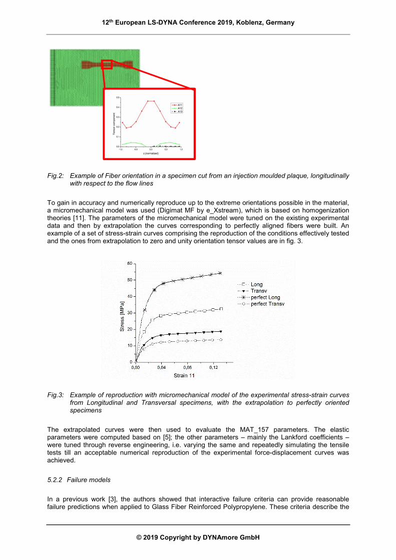
To gain in accuracy and numerically reproduce up to the extreme orientations possible in the material, a micromechanical model was used (Digimat MF by e_Xstream), which is based on homogenization theories [11]. The parameters of the micromechanical model were tuned on the existing experimental data and then by extrapolation the curves corresponding to perfectly aligned fibers were built. An example of a set of stress-strain curves comprising the reproduction of the conditions effectively tested and the ones from extrapolation to zero and unity orientation tensor values are in fig. 3.
Fig.3: Example of reproduction with micromechanical model of the experimental stress-strain curves from Longitudinal and Transversal specimens, with the extrapolation to perfectly oriented specimens
The extrapolated curves were then used to evaluate the MAT_157 parameters. The elastic parameters were computed based on [5]; the other parameters – mainly the Lankford coefficients – were tuned through reverse engineering, i.e. varying the same and repeatedly simulating the tensile tests till an acceptable numerical reproduction of the experimental force-displacement curves was achieved.
5.2.2 Failure models
In a previous work [3], the authors showed that interactive failure criteria can provide reasonable failure predictions when applied to Glass Fiber Reinforced Polypropylene. These criteria describe the

12th European LS-DYNA Conference 2019, Koblenz, Germany
© 2019 Copyright by DYNAmore GmbH
failure of a material as a function of the stress or strain tensor components, which are combined into a functional that denotes material failure when a threshold level is reached. In this publications, the interactive criteria of Tsai-Hill and Tsai-Wu were put to the test in the reproduction of a benchmark case, and the general predictions were in good agreement with the experimental evidence, even when the simplified anisotropy model discussed above was used. After that study, which was carried out though user subroutines coupled with LS-DYNA MAT_103, the same criteria were implemented in the commercial version of the software within the material law MAT_157 and are then available for it. For the present study, based on such prior experience, the Tsai-Wu criterion was chosen. Its functional is expressed as a combination of parameters which need to be identified based on material strengths, measured under different loading conditions [3]. However, according to the approach here above presented, the strengths to be considered are those associated to the perfectly oriented material, which are not within the experimental evidence and need some way to be envisaged. A sort of “thumb rule” was considered for the present study, by which the elongation at break was linearly interpolated between the known values of the average orientation tensor principal component a11, and then extrapolated to the fully oriented values a11=0 (perfectly transversal) and a11=1 (perfectly longitudinal). The values of elongation at break so obtained are then referred to the corresponding stress- strain curves to derive the requested strengths. An example of this procedure is in fig. 4.
5.2.3 Mapping
Finally, an improvement with respect to previous modelling approach is in mapping, i.e. in the way the process-induced orientation, obtained from mold filling simulation, is transferred to the structural mesh. The mapping tool originally used considered the QUAD elements in the structural mesh as “parents” of two triangular elements in the mold-filling simulation mesh. This posed some restrictions in the size and quality of the meshes. For the present work the mapping tool ENVYO [10] was chosen, which is a new mapping software available for LS-DYNA users and removes the limitations previously encountered, making the two meshes substantially independent. Differently from the previous approach, now the average fiber orientation was input from the process simulation carried out with the commercial software Moldflow by Autodesk, using the RSC model for orientation prediction.
Fig.4: The elongation at break for perfectly oriented specimens was extrapolated from the known values measured from the Longitudinal and Transversal Specimens (and at 45° when available), based on the orientation tensor principal component a11.

12th European LS-DYNA Conference 2019, Koblenz, Germany
© 2019 Copyright by DYNAmore GmbH
6 Results and Design review The impact conditions were simulated imposing an initial rotational velocity such as to generate an impact speed corresponding to the requirements. The inertias and mass of the bar holding the adapter and its support were considered. The impacted target was assumed as perfectly rigid. Several impact angles were tested, and then the most critical one, corresponding to the impact of the corner over the fixing screw hitting the target, was chosen for all the materials. This was done with the aim of adopting a conservative approach. The material cards were built up using material data interpolated at T=-10°C from tests carried out at T=-20°C and T=23°C. Additional tests were carried out at T=-10°C to verify the quality of the interpolation and to derive the strengths and strains at rupture. For all the glass fiber reinforced materials, the rupture criterion according to Tsai-Wu was used as described above. Tetrahedral elements of about 2.5 mm side were used instead of bricks, which would have been more desirable, due to the object geometry shape which made difficult obtaining more regular meshing. Regarding the glass fiber reinforced materials, on fig. 5 the final damage – represented by the plot of the deleted elements - observed in the simulation of the two glass fiber reinforced PP-grades is shown. The images are taken for both the simulations when the part has about the 5% of its initial kinetic energy. Although to a different extent of damage, the behaviour of the parts made of the two materials is similar. In fact, there is a progressive damage occurring on the top corner, right where the impact occurs, which was more severe for the 25% GF-PP; however, more concerning was the stress concentration occurring in proximity of the fixing screw, which ends up in a local rupture, although limited to few elements in the simulation. Therefore, the design of the adapter was modified, avoiding sharp corners and saddle points in its shape, since these were recognized as stress concentrators.
Fig.5: Final damage, represented at the end of the impact sequence by the plot of the deleted
elements, for the 25% (left) and the 40% (right) GF-PP adapters
The impact simulations on the part according to the new design were carried out, and the results are shown in fig. 6, reported for the 40% GF-PP homopolymer copolymer at the instant when the maximum stresses are recorded at the location recognized as critical. It is clear from the plots that the new design helps in flattening and smoothing the stress distribution. Accordingly, the final damage on

12th European LS-DYNA Conference 2019, Koblenz, Germany
© 2019 Copyright by DYNAmore GmbH
the part is mainly limited to the impacted area, as displayed by the plot of the deleted elements on the part at the end of the transient on Fig. 7(a). In fact a trace of material damage is also on an edge of the structure (circled on Fig. 7), limited to one element, which was subjected to high compressive stress and was observed, but not with all the element formulations that were tested; additionally, rupture was predicted in some elements in the contact area of the fixings, but this was assessed as not being relevant, due to rough approximations in modelling the fixing screw and its contacts.
Fig.6: Stress concentration in the old (left) and new (right) design of the adapter made of the 40%GF-PP, through the plot of Max. principal stress at the transient time when peak values are reached
Fig.7: Final damage – through the plot of deleted elements (left) - in the new design of the adapter, and resulting damaged part at the end of the simulation (right). Material: 40% GF-PP
7 Validation test The results of the simulations on the old and new adapter design encouraged the manufacturing of the mould according to the new design and the moulding of exemplars made of the 40%GF-PP. These were then submitted to a drop test at Polytech labs, reconstructing the test which was so far only conceptually devised. Samples were kept in freezer for 24 h at -18°C. A 3m long prop holding the adapter, fixed to its support, was anchored to the ground with the possibility for it to rotate around the

12th European LS-DYNA Conference 2019, Koblenz, Germany
© 2019 Copyright by DYNAmore GmbH
fixing, and then it was let to hit a hard obstacle falling onto it from aheight of 1 m. Part temperature was measured just after impact. The experimental layout is visible on fig. 8. On the right side of the same figure, the image of one tested exemplar is shown. As visible, only a damage in the upper corner, where the part impacted, is observed, with good alignment to the simulation result on fig. 7.
Fig.8: Experimental layout in Polytech Laboratories to reproduce the impact conditions analyzed in simulation (left) and impacted exemplar (right)
8 Conclusions The design of the part here presented, for building and construction industry, implied the definition of static and dynamic structural specifications; the software LS-Dyna was suitable for the verification of the design under impact conditions and its indications were useful for improving the part design. The simulations requested extending a methodology developed by LyondellBasell for early stage design, making it suitable for 3D simulations with higher accuracy. This development took advantage of the recent availability of the mapping tool ENVYO by Dynamore. Finally, the experimental verification of the impact confirmed the prediction of the damage and ruptures on the part predicted by the Tsai-Wu failure model.
9 Literature [1] M.Nutini, M.Vitali " Simulating Anisotropy with LS_DYNA in Glass-Reinforced, Polypropylene-
based Components", 9th LS-DYNA German Forum, Bamberg, 2010 [2] M.Nutini, M.Vitali " Characterization of Polyolefins for Design Under Impact: from True Stress/
Local Strain Measurements to the F.E. Simulation with LS-Dyna Mat. SAMP-1", 7th LS-DYNA German Forum, Bamberg, 2008
[3] M.Nutini, M.Vitali, “Interactive failure criteria for glass fibre reinforced polypropylene: validation
on an industrial part”, International Journal of Crashworthiness, 2017, DOI: 10.1080/13588265.2017.1389629
[4] R.Balieu, F.Lauro, B.Bennani, R.Delille, T.Matsumoto, E.Mottola: " A fully coupled
elastoviscoplastic damage model at finite strains for mineral filled semi-crystalline polymer ", Int. J. Plasticity,Vol. 51, p. 241-270, 2013
[5] A.Hatt , "Anisotropic modeling of short fibers reinforced thermoplastics materials with LS-
DYNA", 13th LS-DYNA German Forum, Bamberg, 2014

12th European LS-DYNA Conference 2019, Koblenz, Germany
© 2019 Copyright by DYNAmore GmbH
[6] G.Gruber, A.Haimert, S.Wartzack, “Consideration of Orientation properties of Short Fiber Reinforced Polymers within Early Design Steps", 12th International LS-DYNA Users Conference, Detroit, 2012
[7] J.Lemaitre, J.L.Chaboche., “Mechanics of Solid Materials”, Cambridge Univ. Press, 2000 [8] S.Koellling, A.Haufe, M.Feucht, P.DuBois, “SAMP-1: a Semi-analytical Model for the Simulation
of Polymers”, 4th Ls-dyna Anwenderforum, Bamberg, 2005 [9] M.Nutini, M.Vitali,, “Validation of a SAMP-1 material Card for Polypropylene-based Materials”,
LS-DYNA German Forum, Filderstadt, Germany, 2013 [10] ENVYO User manual, Dynamore, 2018 [11] M I. Doghri, C.Friebel, “Effective Elasto-Plastic Properties of Inclusion-Reinforced Composites.
Study of Shape, Orientation and Cyclic Response”, Mechanics of Materials 37 , 2005, pp. 45-68.
[12] M.Nutini " Failure criteria for polypropylene-based compounds: current developments with
MAT_157”, infoday on Composites at Dynamore, Bamberg, 2017