Embed Size (px)
Citation preview
Charles Kim, Brett Livingstone, Daphne Chen, Miranda Wong, Brian Lee, Michael Yang
Polymerization
2 types of polymerization reactions
o Condensation
Requires a molecule with 2+ functional groups
-OH, -COOH, -NH2, -X
When bonding happens, there is a byproduct
OH + OH Ester bond + water
COOH + OH Ether bond + water
o Addition
Requires a molecule with 1+ unsaturations
For example, unsaturation could be C = C
When bonding happens, there is no byproduct
An initiator is needed to start the reaction
Mechanism: initiator gets activated into a free
radical which is used to attack the
unsaturation and start polymerization
Activating initiators using energy
UV light
Heat: benzoyl peroxide’s O-O bond gets
broken when temperatures reach 90~100C
and yields free radicals. Used in dentures
Visible light: camphorquinone becomes a free
radical when exposed to 468 nm (see below).
Used in composites.
Activating initiators using chemicals
Benzoyl peroxide + Tertiary amine: the amine
attacks the benzoyl peroxide, resulting in
radical formation
How do you know if your dental material is using
energy or chemical assisted activation?
Energy: need to put the material in heat,
under light, or shine something on it
Chemicals: the material comes in 2 packages
and requires mixing before use
How much initiator is good?
o High [initiator] = high chance for an initiator to meet a
monomer and polymerize it. Form lots of small
polymers
= Low molecular weight but fast setting time
o Low [initiator] = Initiator can only start reaction in a
few areas, mostly monomer-monomer bonding
= high molecular weight but slow setting time
o In real life: camphorquinone is used at 0.2%
Polymer classification
Linear Branched + cross linked
.
2 functional groups or 1 unsaturation needed in each monomer
2+ functional groups or 1+ unsaturation needed in each monomer
Binds to other polymers via secondary bonds
Binds to other polymers via primary bonds
Susceptible to temperature changes
Not as susceptible to temperature changes
o How to make a primarily branched polymer
Get a mixture of monomers
Some with 2FG’s/1UG forms linear chains
Some with 2+ FG’s/1+ UG forms branches
During the polymerization phase, the linear
portions will form and attach as branches due to
the cross linking monomers
Co-polymer clasification
o Co-polymer: a polymer made up of more than 1 type
of monomer (we’ll use notation M1 and M2)
o Random copolymer
M1M2M1M1M1M2M1M2 - etc
Random organization
o Block copolymer
(M1)X – (M2)Y – (M1)Z – etc
M1 and M2 are polymerized independently to form
short oligomers
Then, they are mixed together to polymerize the
blocks of oligomers
Used in medicine for urethanes. Linear urethanes
(M1) are flexible and aromatic urethanes (M2) are
rigid. By controlling their ratio, you can make a
material with the desirable properties
o Graft copolymer
Long backbone of M1 with branches of M2
attached to it
Polymerization shrinkage
o The material contains monomers which are bound to
each other by secondary bonds
o Once polymerized, these secondary bonds become
primary bonds which has a significantly smaller bond
length

Charles Kim, Brett Livingstone, Daphne Chen, Miranda Wong, Brian Lee, Michael Yang
Polymers are viscoelastic
o Low strain rate = the polymers can slide past each
other slowly = low modulus
o High strain rate = polymers don’t have time to
untangle, hence undergoing less strain with the same
stress = high modulus
o Viscoelasticity means a material’s stress-strain curve
(and hence modulus) is strain rate dependent
o Note: the changes in modulus are far less significant
in cross linked polymers compared to linear polymers
Because polymers are viscoelastic, they have a glass
transition temperature (Tg)
o Low temperature = polymers cannot break and re-
form secondary bonds very easily due to low energy =
the material has a high modulus = acts like glass
o High temperature = polymers break and re-form
secondary bonds with ease, conforming to the strain
applied = acts like rubber
o In between rubbery/glassy temperature, the polymer
displays leathery characteristics
o Glass transition temperature is the temperature at
which the polymer transitions between the glassy
and rubbery properties
Glass transition temperature graph
o <90°C = polymer is glassy therefore modulus is high
o 120~180°C = polymer is flexible and rubbery
o >180°C = polymer melts
o Note: X axis is on a log scale, so each unit on the X axis
denotes a 10x increase in modulus
Changes to the graph due to polymer type
o When a polymer is linear, the polymers can move past
each other easily once above the glass transition
temperature
o When a polymer is cross linked, the polymers still have
difficulty moving past each other despite being above
the glass transition temperature
o When a polymer becomes cross linked, there is a
smaller change in modulus between glassy/rubbery
states (as mentioned before). The Tg does not change

Charles Kim, Brett Livingstone, Daphne Chen, Miranda Wong, Brian Lee, Michael Yang
Resin composites
Composite: material system composed of a combination
of 2+ micro/macro constituents that differ in form and
chemical composition and which are essentially insoluble
in each other
Main constituents
Matrix Filler
-Polymers (BisGMA, UEDGMA) -Metals -Ceramics
-Silica or silica based glasses and ceramics -Can be organized into spheres, fibers, or flakes
o Amalgam composites are made of metal and metal
o Resin composites use polymer for their matrix and a
filler
Minor constituents
o Activator, inhibitors, antioxidants, coupling agents
(MPTS), pigments, radiopaque components
Types of fillers
o Fibre
Length is the dominant dimension
Ec = kVfEf + VmEm
The modulus of the composite is based on the
modulus and relative volume of the filler and
matrix
Relative volume, not relative weight
K = direction of the fiber
K = 1 all fibers orientated in 1 direction
K = 1/2 bi directional fibers
K = 1/3 random in plane
K = 1/6 random in 3D
Fibrous fillers are not used in dental composites
because it is not possible to ensure that all fibers
are orientated in the same direction
o Flake
Surface is the dominant dimension
Will not be further discussed
o Sphere
No predominant dimension
This is used in dental composites
Calculating the modulus is discussed below
Spherical fillers
o E = modulus of elasticity (AKA measure of stiffness)
𝐸𝑐𝑜𝑚𝑝𝑜𝑠𝑖𝑡𝑒 =1
(𝑉𝑜𝑙𝑢𝑚𝑒𝑓𝑖𝑙𝑙𝑒𝑟
𝐸𝑓𝑖𝑙𝑙𝑒𝑟) + (
𝑉𝑜𝑙𝑢𝑚𝑒𝑚𝑎𝑡𝑟𝑖𝑥
𝐸𝑚𝑎𝑡𝑟𝑖𝑥)
o Plot the formula
X axis = % of filler used in the composite
Y axis = stiffness of the composite (compared to
the baseline [100% matrix, 0% filler])
You need more than 60% filler (Vf > 60) to
improve the strength of the composite by 2x
o Plotting the same formula but with varying strengths
of the fillers (X axis) and varying amounts (Y axis)
Red = the filler is 100x stiffer than the matrix. This
is a very good filler. However, it only makes up
10% of the composite. Therefore, there is hardly
an increase in the total modulus (↑ 1.1x)
Blue = the filler sucks (only 10x stiffer than the
matrix). But, a lot of it is used (85%) and resulted
in a 4.25x increase in the composite’s modulus
Conclusion: the strength of the filler hardly
matters. What matters is how much of it you use
in your composite
Even a simple calcium carbonate filler (only about
10~15x stronger than matrix) can increase the
strength of the composite significantly if enough
is used
“Best bang for your buck”
Real life modulus values
o Dentin is 18 GPa
o Enamel is 84 GPa
o Resin is 1~3 GPa
Not even comparable to dentin, fillers needed
o All purpose composite = 10~20 GPa
o Anterior composite = 6~20 GPa
o Posterior composite = 10~25 GPa

Charles Kim, Brett Livingstone, Daphne Chen, Miranda Wong, Brian Lee, Michael Yang
Polymers used in dentistry
o Methacrylate The mother of all polymers
Has 1 unsaturated bond =
addition reaction
polymerization
Activated through heat (via benzoyl peroxide),
UV, or visible light (via camphorquinone)
o Bis-GMA (Bis-Phenol A Glycidylmethacrylate)
Methacrylate groups (green) polymerizes
Multiple unsaturations cross links
Glycerol (red) and bisphenol backbone (blue)
gives rigidity to the monomer
Too viscous to use in practice
o TEGDMA (Tryiethyleneglycol dimethacrylate)
Methacrylate groups on the ends polymerizes
Ethlyene glycol backbone less rigid than
BisGMA, much more flexible
Not as viscous
TEGDMA and BisGMA are combined
Posteriors: 25% BisGMA, 75% TEGDMA
Flowables: more TEGDMA
o UDMA
Urethane based invented for dental materials
More flexible than BisGMA
Created to replace BisGMA due to safety concern
o MPTS (γ methacryloxypropyl trymethoxy silane)
Called a coupler which binds the resin polymers
to the SiO2 glass filler particles
Methacrylate group on one end polymerizes
Silanol group on other end bonds to silica filler
How is this prepared in real life?
Grind up glass (SiO2) to desired size
Expose glass to MPTS
Rinse in ethanol to remove excess MPTS
Yields glass particles with MPTS coating
which will polymerize with the resin
In the presence of water
The bonds between glass and MPTS can
break because it is a weak ether link
Can compromise strength of composite
Polycarbonate plastics and public health concerns
o Type of plastic made of BPA and phosgene, which is
versatile and used in glasses, shields, etc
BPA: bisphenol A (blue part in bis-GMA)
Phosgene: polycarbonate molecule
o Why is BPA such a concern?
Molecules with benzene rings and a OH group
attached are known to be xenoestrogenic
Xenoestrogenic compounds bind to estrogen
receptors and can cause hormonal disturbance
BPA has 2 benzene’s with OH’s
If the bond between polycarbonate and BPA is
broken, then the xenoestrogenic compound will
be exposed
o Examples of BPA exposure
Microwaving BPA plastics heat or radiation can
break the polycarbonate bonds and expose BPA
Baby bottles in the dishwasher heat can break
the polycarbonate bonds and expose BPA
o Dental relevance
BisGMA
Structure: BPA + glycerol + methacrylate
Does not have exposed alcohol groups
because the O’s on the BPA form ether
bonds to glycerol
Esterases in the mouth can break the
methacrylate bond to glycerol, but will not
break the BPA + glycerol bond
Risk of BPA exposure is minimal
Sealants
Structure: BPA + methacrylate
There is no glycerol in sealants
This means mouth esterases will break the
methacrylate + BPA bond and expose the
OH on BPA
Risk is possible, but nowadays, sealants are
BPA-free
o Human exposure to bisphenol A by biomonitoring:
Methods, results and assessment of environmental
exposures. Wolfgang Dekant, Wolfgang Völkel (2008)
Daily tolerable intake of BPA is 50 ug/kg/day
Average daily human exposure to BPA is
6ug/person, which means <0.1 ug/kg/day
We are 500x lower than the daily limit

Charles Kim, Brett Livingstone, Daphne Chen, Miranda Wong, Brian Lee, Michael Yang
Classification of composites
o Based on filler size (in um)
Meaningless, when talking about mechanical
properties of the material
Manufacturers will still advertise this info though
However, can be useful in determining if the
composite will be esthetic
Visible light is 450~750 nm
You want the particles to be <1/2 this
wavelength because otherwise it will
undergo specular reflection (looks ugly)
So, you want particles to be <200 nm
Particle size and surface area
As the filler particle size gets smaller, their
esthetics improve but the surface area
increases exponentially
Example: say there was 40mm3 of filler
o 1 big particle = 56.55mm2 surface area
o 1021 particles = 262m2
surface area
o ↓ particle size = ↑ surface area = ↑
bonding+strength
o However, ↓ particle size will require
more resin to interact with the increasing
surface area. Thus, %Vf will have to
decrease if you want the resin to be able
to coat each filler particle
o This problem is seen for micro and nano
filled composites, hence their weak
properties
Macro filled >5 um -Poor wear, cracks propagate, looks ugly
Micro filled 0.04~0.4um -Good esthetics -Only done in low Vf
Small particle 1~3um -Short lived, rarely used
Hybrid 0.04~3um -Excellent mechanical properties
Micro hybrid Nano hybrid
0.004~3um -Nice esthetics but not load bearing (weak)
o Based on % of filler (Vf)
Midway filled (<60%) esthetics
Ultrafine (<3um) or fine (>3um)
Compact filled (>60%) load bearing
Ultrafine (<3um) or fine (>3um)
This method of classification is much more useful
to clinicians but it is not frequently used
As a clinician, you should always ask: what is the
Vf and modulus of the material
Why can’t we just keep adding filler to make
composites stronger and stronger?
Practical limitation: the material becomes
too viscous and hard to work with
Theoretical limitation: the amount of
volume that spherical fillers can occupy has
a limit. See packing efficiency
Packing efficiency
o Cubic lattice
The matrix will be broken
down into units called “cells”
which are cubes
Each corner on the “cell” will
represent the center of a sphere
Each corner of the cube has 1/8 of a sphere
The cube has 8 corners
8 x 1/8 = 1 sphere worth of volume per cell
Volume of 1 sphere is 4πr3/3
Volume of the cube is (2r)3
Vf = Vspheres/Vcube = (4πr3/3) / ([2r]3) = 0.5236
If a matrix has spherical fillers organized in a
cubic lattice, then 52% is the theoretical upper
limit of filler possible
o Face centered cubic lattice
Each corner has 1/8 of a
sphere like before
Each face has 1/2 of a sphere
1/8 * 8 corners + 1/2 * 6 faces
= 4 spheres of volume per cell
Volume of 1 sphere is 4πr3/3
Volume of the cube is (2.828r)3
Because the spheres have to be smaller to
allow face-cubes to fit, each dimension of
the cube has to be 2.828r, not 2r
Vf = Vspheres/Vcube = [4*(4πr3/3)] / [(2.828r)3] = 0.74
If a matrix has spherical fillers organized in a face
centered cubic lattice, then 74% is the
theoretical upper limit of filler possible
o In real life
It is not possible to reach the theoretical 74%
However, having hybrid sizes of particles (bimodal
distribution) means that the smaller particles can
squeeze between the larger spheres and get
closer to the 74% limit
Values used to determine composite strength
o Modulus of elasticity (GPa)
How much deformation there is with a defined
amount of stress
Dentin is 18 GPa, Enamel is 84 GPa
Resin composite 18~20, Gold 77, Ceramic 70~80,
Amalgam 34
This is the value that we should look at
o Compressive strength (MPa)
How much stress the material can handle (does
not account for deformation)
Dentin is 297 MPa, Enamel is 384 MPa
Resin composite is 250~450
Compressive strength is not the limiting factor,
but this is the value reported by manufacturers
to give the impression that it is “comparable” to
teeth strength

Charles Kim, Brett Livingstone, Daphne Chen, Miranda Wong, Brian Lee, Michael Yang
Thermal expansion
o Important because restorative material needs to
expand and shrink similar to natural teeth. Major
discrepancies can cause leakage of restoration or
stress on tooth
o Coefficient of thermal expansion (α) in ppm/ᵒC
Enamel = 11.4 Dentin = 8.3
Composite = 23~40 (closer to 40)
Amalgam = 25
o Force applied on tooth walls due to thermal
expansion
𝐹𝑜𝑟𝑐𝑒 𝑜𝑛 𝑡𝑜𝑜𝑡ℎ = 𝐸 ∗ 𝛼 ∗ ∆𝑡𝑒𝑚𝑝 ∗ 𝑎𝑟𝑒𝑎
Amalgam Composite
F = 34*22*∆temp*area F = 15*40*∆temp*area
F = 850*∆temp*area F = 600*∆temp*area
Polymer shrinkage
o Uncured = particles adhere through secondary bonds
o Cured = particles adhere through primary bonds
o Primary bonds are much stronger and bond length is
significantly reduced will lead to shrinkage
o Configuration factor (C factor)
Imagine the composite glob as a cube
C = # of bonded surfaces / # of free surfaces
If placed on a free surface, C = 1/5 = 0.2
If placed in a “cup” (like class 1 prep), C = 5/1 = 5
↑ C factor = ↑ stress due to shrinkage
To minimize C factor in restorations, place in
increments
o Coefficient of H2O resorption
The composite will absorb H2O from the pulp and
the environment for the next 24~48 hours
This compensates for the shrinkage
Light curing
o Goal is to activate the photoinitiator
Example: camphorquinone(needs 468 nm light)
Halogen lights emit in a wide spectrum = can cure
various composites
LED’s are monochromatic = can’t cure all
composites
o Energy of the light decreases exponentially with
distance, it is crucial to be as close to the composite
as possible
o Light intensity can be weak on the edges of the
curing unit
o Polymerization is measured by degree of conversion
o Cannot achieve 100% conversion, deal with it
Alternative composite materials
o Compomers (composite ionomer)
Resin matrix contains carboxylic groups
Also called polyacid modified composites (PAMC)
No H2O involved like GIC
Low Vf and questionable filler-matrix bonding
Like composite, but worse properties
o Packable composite
Viscous characteristics to mimic amalgam
No advantages
o Polymer ceramic
Not a ceramic – misnomer
Used for indirect restorations, lab processed
May contain ceramic-like components, but it is
nowhere comparable to the strength of a ceramic
Some manufacturers will advertise that they use
ceramic fillers, but remember that filler strength
has a very small influence on overall strength of
the composite. The Vf matters the most
o Flowable composite
Low viscosity with low Vf
Questionable mechanical properties
May be suitable as liners, but avoid exposure to
occlusal/oral environment
Modulus = 9 GPa
Useful when you are trying to pack composite
into the preparation. Adhesive is slippery and the
composite will stick to your instrument. Applying
a thin layer of flowable can help with this, and
preserve the thin adhesive layer
o 3M ESPE Nanocomposite
Fillers are are silane treated to provide cross link
to surrounding resin
Broad filler distribution high Vf
Due to so much surface area, they can get very
viscous
Cannot be silinated completely and coupled to
bond to the matrix
Long term behaviour is concerning
Water could seep in
o Polyhedral oligomeric
silsesquioxane (POSS)
1 silicon : 1 oxygen ratio
Has a cage
After 10% filler, properties sucked
Comes out in literature, but be aware its success
is not that great
o Silorane composites
Uses epoxy groups which open up once
polymerized and prevents polymer shrinkage
Mechanically, not that great
o Thiol polymers (came out in 2014!)
Promised 90~95% degree of conversion
Currently no long term studies

Charles Kim, Brett Livingstone, Daphne Chen, Miranda Wong, Brian Lee, Michael Yang
Impression materials
Characteristics desirable in an impression material
o Pleasant odour, taste, and aesthetic colour
o Free of toxic or irritant constituents
o Adequate shelf life for requirements of storage and
distribution
o Economically commensurate with the results
obtained
o Easy to use with minimum equipment
o Setting characteristics that meet clinical
requirements
o Satisfactory consistency and texture
o Readily wets oral tissues
o Elastic properties that doesn’t permanently deform
after being strained
o Will not break upon removal from mouth
o Dimensionally stable over humidity/temperature
changes for a long enough time to cast or die
o Compatibility with cast or die materials
o Accuracy in clinical use
o Readily disinfected without loss of accurary
Classification of impression materials
Rigid Elastic
Irreversible -Plaster (gypsum) -Zinc oxide eugenol
-Elastomers (polysulfide, polyether, polysilicone) -Alginate
Reversible -Compound -Wax
-Hydrocolloid agar
o Rigid = for edentulous patients
Note: being rigid does not mean that the material
cannot be elastic. The material is more resistant
to deformation
High E
o Elastic = for dentulous patients
Used in dentulous patients to conform around the
undercuts of the teeth
Low E
o Reversible = the material sets based on temperature
changes, and can revert back to its original state
o Irreversible = sets by chemical reaction
Old people and people with implants have weakly
attached teeth
o They can fall out during impressions
o Always lubricate teeth that are mobile
o Always lubricate implants
o It will not affect impression clarity
Alginates
Properties of alginates
o Elastic
E value is low
Needed to conform around the teeth
o Hydrocolloid
What is a colloid?
Suspensions: >500 nm sized particles
Colloids: 200~500 nm sized particles
Solutions: atomic sized particles
Colloids and suspensions will distort light
because they are >1/2 the wavelength of
light
The dispersing medium is called an aerosol
(if it is air), and hydrosol (if it is water)
The dissolved material is called the
dispersed phase
Properties of colloids
Undergoes a reversible reaction of
liquefying (Sol) and solidifying (Gel)
o Sol ↔ Gel
o Temperature dependent
Alginate hydrocolloid
o Considered an irreversible hydrocolloid
because in clinical use, we never reach
the temperatures needed to trigger the
reversible reaction (Sol ↔ Gel)
Goes into the gel phase via a chemical
reaction rather than via a temperature
reaction
o Irreversible
Alginic acid – not soluble in water, so not
very useful. Reacted with sodium
Sodium alginate – soluble in water and this
is the “white powder” that we see
Calcium alginate – insoluble in water. This is
the set form of alginate, which is irreversible

Charles Kim, Brett Livingstone, Daphne Chen, Miranda Wong, Brian Lee, Michael Yang
Setting reaction of alginates
o Chains of sodium alginate are reacted with calcium
Since calcium is divalent, it will want to bind to 2
things to satisfy the octet
Replacing the Na on 1 alginate chain will only
satisfy 1 bond, so calcium binds to 2 alginate
chains
Cross linking of alginate chains solidifies the
material and this is the set form of the impression
material
o Source of calcium
Calcium is provided by gypsum (CaSO4*2H2O),
which is called the “reactor”
o This reaction is very quick
The material will set too quickly to be useful
A “retardant” is needed to slow the reaction
Retardant can be K3PO4 or Na3PO4
PO4 ions have a strong affinity for calcium, so they
scavenge and compete for free Ca ions
Sodium alginate will not cross link until all of the
PO4 ions are depleted
o In clinical practice, this all appears as a white powder
o Always put powder into water to reduce formation of
aggregates and having dry alginate stick to the bowl
Molecular structure
o Referred to as a “brush heap” structure
o Water is entrapped between the
polymer strands
Mechanical properties
o Viscoelasticity – the modulus of the alginate depends
on the strain rate
If load is applied slowly, the water can slowly
ooze out and deform the structure. Low modulus
If load if applied quickly, the structure retains its
original form as water cannot displace as much
o Imbibition and syneresis
The relative humidity of the oral cavity is about
80% and the temperature is about 32C
When the alginate sets, it sets in equilibrium in
this environment
When removed from the oral cavity, the
environment humidity and temperature changes
This can deform the alginate, in one of 2 possible
ways
Imbibition: swelling and absorption of H2O due to
higher relative humidity
Syneresis: shrinkage due to loss of H2O
Reintroducing a material that underwent
syneresis back into water will not restore its
original shape
To preserve the accuracy of the impression, a
moist towel and Ziploc bag is recommended
Desirable mechanical properties of alginate
o Compressive strain
Apply 0.1 MPa for 30 seconds
The change in dimension L is calculated as ε
ε = (Lf – L0) / L0
5% < ε < 20% o Elastic recovery
The material is compressed by 20% for 5 seconds
The material should recover to at least 95% of its
original size
Elastomers recover by 96.5%
o Tear strength
Force required to tear the material
How to improve accuracy of impressions in the undercut
areas of the teeth
o L0 = thickness of
the alginate in
the area of the
undercut
o U = thickness of
the undercut
o L = how much the
alginate needs to
compress in
order for the
impression to be
removed
o Compressive strain
ε (compressive strain) is proportional to σ (stress),
so we want to minimize ε
ε = (L – L0) / L0
Substitute L+U for L0
ε = (L – (L+U)) / (L+U)
ε = - U/(L+U)
We want to minimize ε, but U cannot be
modified. Therefore, L is the only variable we can
influence
To minimize ε, L has to be as big as possible
Conclusion: the thicker the alginate (L), the less
strain/stress that the impression undergoes
Use stock trays to ensure proper thickness
all the way around the arch
Charles Kim, Brett Livingstone, Daphne Chen, Miranda Wong, Brian Lee, Michael Yang
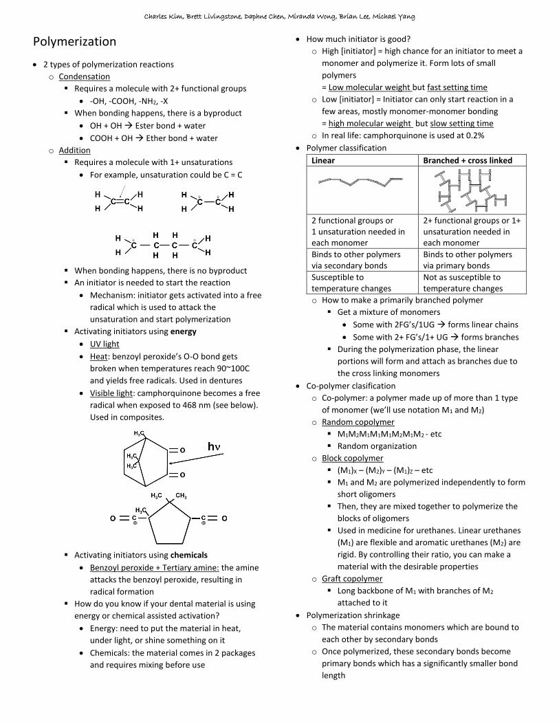
Elastomers
Polysulfides Polyethers Polysilicones (siloxanes)
Background -Originated from “isoprene” -Mostly used for crown and bridge impressions -Rotton egg smell -Possible lead exposure
-Newest elastic elastomer -Used in edentulous or implant patients (high accuracy needed) -Expensive
-Most popular impression materials, with polysiloxanes being more popular -Can be stored, repoured, etc -VERY dimensionally stable (few/no byproducts)
Properties -Polysulfides don’t wet very well (has a high contact angle). Slightly hydrophillic -Viscoelastic (remove from patient swiftly) -Some shrinkage as water is a byproduct (can evaporate)
-The only hydrophilic elastomeric material (low contact angle) -Expensive -Early polyethers were stiff (high E) hard to remove -Shelf life not as good as siloxanes
Condensation silicones -Because this is a condensation reaction (EtOH is a byproduct), shrinkage will happen -Inherently hydrophobic – dry mouth before use
Addition silicones -Uses a platinum catalyst (expensive) -If there is residual water or some of the silicone monomers contain OH instead of vinyls, then there will be H2 bubbling during setting due to Pt -Inherently hydrophobic – dry mouth before use
Structure
-R – S – S – R -
(This is the monomer)
Poly dimethyl siloxanes
Polymethyl siloxanes
Polysiloxanes
Polymerization reaction
-Functional group is the R-SH group (called the merceptan or thiol group) -Undergoes oxidation reaction 2R-S0H0 + PbIVO2 R-S0-S0-R + PbIIO + H1
2O -Lead gets reduced (PbIV PbII), so it is the oxidizing agent -Hydrogen gets oxidized (H0 H1) -Lead is commonly mistakenly called a catalyst, but it is not -Each monomer needs to contain more than 1 SH group to allow cross linking
Making the monomer -Starts with aziridine attached to butanoic acid
-The COOH group is reacted with the ether groups in tetrahydrofuran (left) or ethyleneoxide (right)
-This yields the monomer seen below
Making the polymer -The aziridine ring is under a lot of stress. When reacted with an aromatic sulfonate ester, the ring breaks open and reveals a cationic carbon
-The cation will attack the N on the next aziridine ring -This is cationic polymerization
Condensation silicones -Monomer is α,ω-hydroxy-poly dimethyl siloxane. Alone, this monomer only has 2 functional groups so it will only form linear chains
-It is reacted with tetraethyl orthosilicate which has 4O’s to allow cross linking
Addition silicones -Monomer is α,ω-vinyl-poly (dimethyl siloxane) Or α,ω-vinyl-poly (methyl siloxane)
“Hydrophillic” polyvinyl siloxanes
-New on the market -1 end is hydrophobic, 1 end is hydrophillic -Acts as a surfactant -Does not chemically bind to polymer

Charles Kim, Brett Livingstone, Daphne Chen, Miranda Wong, Brian Lee, Michael Yang
Exists in light body, medium body, heavy body, and putty states
o Each state has an increasing amount of filler and hence higher modulus
o Light body is applied first
Low amount of filler and thus low viscosity
Used to secure critical areas of your impression where you need the greatest amount of accuracy and
detail (eg. around a crown prep and on occlusal surfaces of teeth)
Use a syringe to apply this material so that you can place it exactly where you want and avoid air bubbles
o Then stiffer elastomers are applied over top
Better mechanical properties and thus are used in conjunction with light body to give strength to the
impression
o This technique where you use light body to get details and higher viscosity material to give strength is called the
“wash” technique
o So these different “bodies” are just different consistencies, the chemistry of all of them is the same
Custom trays or stock trays?
o Alginates have poor mechanical properties
So, stock trays are used when taking alginate impressions to ensure adequate wall thickness when
removing the impression
o Elastomers have better mechanical properties
Thickness of the walls is less of a concern
Custom trays can be used which results in thinner walls
Saves material (elastomers are expensive)

Charles Kim, Brett Livingstone, Daphne Chen, Miranda Wong, Brian Lee, Michael Yang
Gypsum
Gypsum products
o Normally, gypsum is in the form of CaSO4*H2O
o Water is incorporated into the crystalline structure
o With a changes in temperature and/or pressure,
gypsum can be changed into different compounds
Hemihydrate (Plaster of Paris)
o This is the form of gypsum that is sold in stores
o There is less water, but not completely absent
o Comes in 2 forms: α and β hemihydrate
Chemically, they are the same
They differ in terms of crystalline structure
Alpha has more desirable characteristics
β hemihydrate α hemihydrate
How it is made (starting from gypsum)
-Calcination -130ᴼC -Atmospheric temperature
-Autoclaving -Higher pressure -Higher temperature
Structure
-Poor crystallinity -High porosity -Irregular shape
-Crystalline -Non porous -Regular shape
Properties -Weaker -Stronger Use -Plaster -Stone
-Die stone
o Setting reaction when water is re-introduced
(CaSO4)2*H2O + 3H2O 2CaSO4*2H2O
Clinically, slightly add more water than this
stoichiometric ratio
Anhydrite
o Formed when gypsum is continually heated past the
hemihydrate stage
o All the water is removed
o Like the hemihydrate stage, there are 2 types of
anhydrites
Hexagonal and orthorombic
They differ in their reactivity to water
Gypsum additives
o Potassium sulfate accelerator
o Sodium sulfate accelerator
o Borax inhibitor
Volumetric change in gypsum as it sets
o Theoretically (determined by math)
Vf = 0.935 V0
6.5% volumetric shrinkage
2.2% linear shrinkage
There should be an overall shrinkage
o Realistically
Gypsum crystallizes in multiple spheres
As the crystals grow, they impinge on each other
Lots of space between the crystals
Gypsum expands, does not shrink
In the presence of extra water, even more
expansion happens due to hygroscopic expansion This is seen more in plasters than gypsums
because plasters are more porous, hence
needing more water
Gilmore needle
o Needle with a weight attached
o Placed on setting gypsum
o Used to calculate the strength of
gypsum or determining its exact
setting time
Setting time
o Water is consumed
o Initially appears glossy
o Turns to matte and dry looking
o Loss of gloss = indicates initial setting time
Can detect this far before the increase in
temperature associated with gypsum setting
Gauging volume
o Volume fraction of pores in the bulk powder
o Measure of free space
o You have to add enough water to gypsum to allow it
to set, as well as fill in the pores (gauging volume) to
let the material be plastic enough to handle
Charles Kim, Brett Livingstone, Daphne Chen, Miranda Wong, Brian Lee, Michael Yang
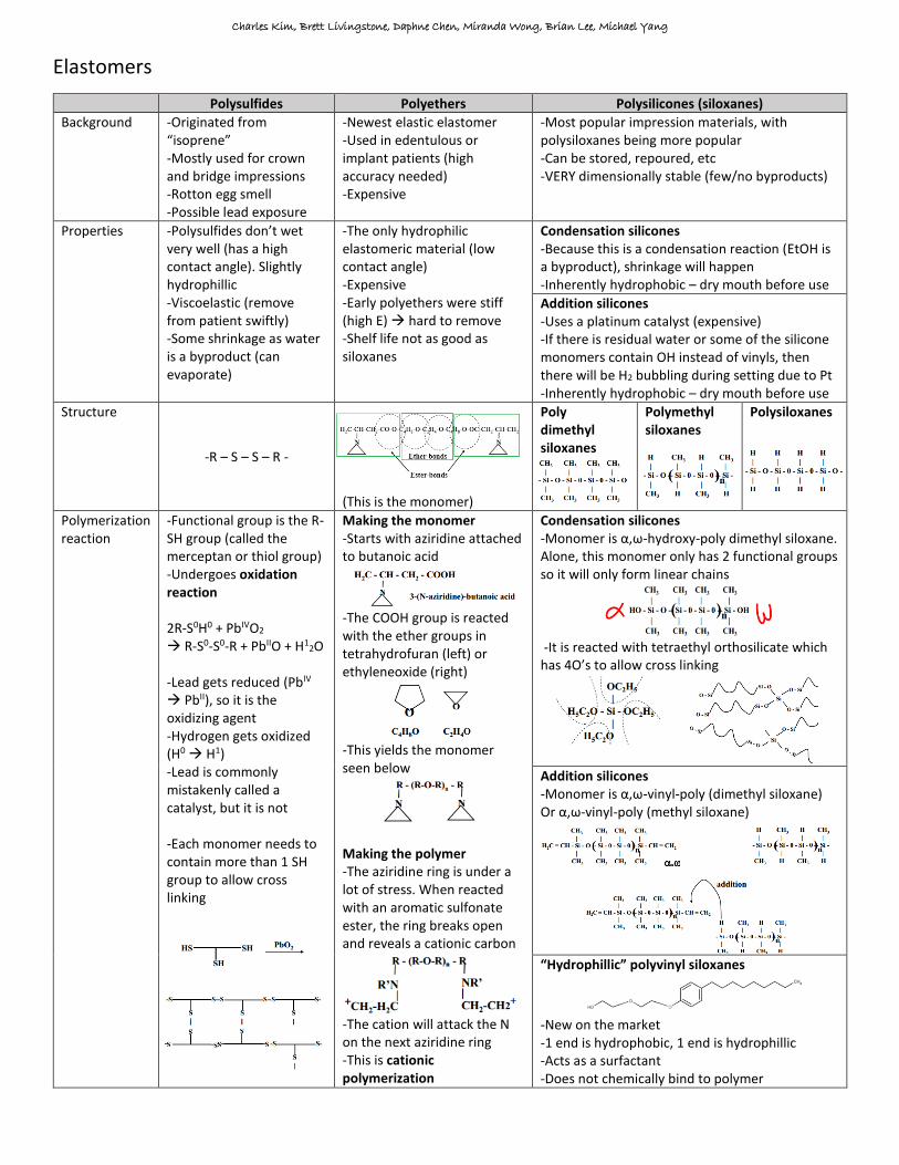
Gypsum strength when rehydrated
o When water is added to hemihydrate, gypsum will
form. If there is any excess water, it will form micro
porosities
More porosities = weaker gypsum
o This table will be on the exam
o Y axis = strength of gypsum yielded
o X axis = how much excess water is added on top of
the stoichiometric ratio
o Dry powder
Has - 0.5 excess water indicates not enough
water
No mechanical properties
o Stoichiometric point
The exact ratio of water is added according to the
gypsum setting reaction
(CaSO4)2*H2O + 3H2O 2CaSO4*2H2O
The maximum strength (top of Y axis at 0.0 excess
water) is a theoretical value. It can never be
reached because it is impossible to make each
water molecule contact each CaSO4 in a perfect
ratio and not form porosities
Hence, you realistically need more water than the
ideal stoichiometric ratio
o Minimum mixing liquid requirement
In a realistic setting, this is the highest achievable
strength for set gypsum
This is because water particles have to coat the
gypsum in addition to reacting with it. Without
coating, it will be too dry and impossible to work
with
Slightly more water than stoichiometric ratio
Due to excess water, its evaporation will form
small porosities, but it is minimized
This excess water (to fill the pores) is called the
gauging volume
o Critical porosity
0.6 volume fraction excess water
Too many porosities in the set gypsum
There is no mechanical strength
Useless
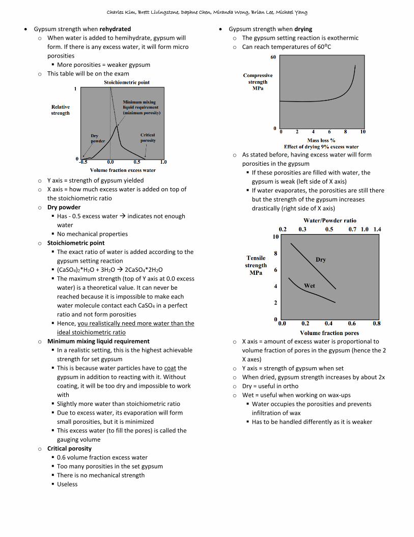
Gypsum strength when drying
o The gypsum setting reaction is exothermic
o Can reach temperatures of 60ᴼC
o As stated before, having excess water will form
porosities in the gypsum
If these porosities are filled with water, the
gypsum is weak (left side of X axis)
If water evaporates, the porosities are still there
but the strength of the gypsum increases
drastically (right side of X axis)
o X axis = amount of excess water is proportional to
volume fraction of pores in the gypsum (hence the 2
X axes)
o Y axis = strength of gypsum when set
o When dried, gypsum strength increases by about 2x
o Dry = useful in ortho
o Wet = useful when working on wax-ups
Water occupies the porosities and prevents
infiltration of wax
Has to be handled differently as it is weaker

Charles Kim, Brett Livingstone, Daphne Chen, Miranda Wong, Brian Lee, Michael Yang
Metals
Types of bonds
o Primary
Ionic – strong and non directional
Covalent – strong and directional
Metallic – strong and non directional
o Secondary
Electrostatic – weak and non directional
Ionic bonds
o Ions
Forms when atoms want to give up or accept an
electron
Goal of the atom is to achieve stable noble gas
configuration by filling its valence electron shell
o Ionic bonds form between 2 atoms with greatly
differing electronegativities (Xa << Xb)
o Structure
Tends to order itself in an orderly lattice
This is to maintain neutrality of charge
Very few defects in crystal
o Properties
Strong and stiff (resists compression/tension well)
If tension is too great, the crystal will crack
No elastic deformation
Brittle
Electrically conductive only if melted/dissolved
Non directional bonds
Covalent bonds
o Electronegativities of the atoms are similar
o Electrons are shared
o Properties
Generally stiff
Brittle
Directional bonds
Metallic bonds
o Positive metal ions surrounded by a sea of electrons
o Each unit electrically neutral and there is no electric
attraction like there is in ionic bonds
o Many defects in the crystalline structure because it
doesn’t need to neutralize charges like ionic bonds
o Not as resistant to change as ionic bonds because
atoms can simply slide past each other
o Properties
Not brittle
It is TOUGH can undergo a lot of deformation
Shear is possible
Is ductile can be drawn out due to atoms
sliding past each other
Electrically conductive without melting
o Exceptions to brittleness
Metals can be brittle if it is very high quality (has
very little defects in its crystal organization)
Cold working the metal
Crystalline lattice possible organizations
o Classified based on dimension size (a, b, c) and angles
between each dimension (α, β, γ)
o Don’t need to know the shapes above, just realize
that crystals can be classified on length and angle of
the dimensions
o In the shapes above, atoms can be placed in various
corners or surfaces
If the atom is in the corner = each atom fills 1/8th
of a crystal unit
If the atom is on an edge = each atom fills 1/4th of
a crystal unit
If the atom is on a face = each atom fills 1/2 of a
crystal unit
Significance = describes how densely packed the
atoms are. The denser the crystal, the stronger
Solidification of metals
o In a liquid bath of melted metal atoms, bring the
temperature down
o The decreased energy in the system will bring the
atoms closer together
o Metal atoms start solidifying by forming “nucleation
sites” of crystallization
o As temperature continues to drop, the nuclei grow
into ‘grains’ in their original orientation
o Each grain has the same properties as the metal
o Slow cooling = grains can orient together slowly =
more uniform metal = weaker (explained later)

Charles Kim, Brett Livingstone, Daphne Chen, Miranda Wong, Brian Lee, Michael Yang
Energy changes during crystallization
o Red line
In a liquid bath, metal atoms are constantly
colliding with each other and forming small
particles
However, the nucleation particles break apart
because of the increase in surface free energy
change
Forming a surface means electrons must act in an
unfavourable way
o Blue line
When particles form, a volume is established
Atoms in the center of the volume do not interact
with the system, so they are basically “removed”
this leaves more energy to the melted atoms
Therefore, forming nucleation particles is
somewhat favourable
o Purple line
Combine the energies of the red and blue lines
Initially, it is not favourable for particles to grow
because the surface free energy counteracts the
volume free energy
Surface free energy is a r2 function whereas
volume free energy is a r3 function. Eventually,
volume free energy will catch up and make it
more favourable to nucleate
If the small particles can clump enough and reach
the critical radius (r*), then nucleation is more
favourable rather than breaking apart again
This happens when you decrease temperature
Phase transition diagrams for a pure component
o During phase transition (liquid solid or vv), there is
no change in temperature because the heat is being
used for the phase change
Alloys come in 2 configurations
o Alloy: metallic compound containing 2 or more
metallic elements
More abundant metal = principle metal
o Substituted alloy: principle metal forms a lattice. The
alloy metal atoms substitute certain positions on the
lattice. For example, some copper atoms replacing
gold atoms in a gold lattice
Diameters of atoms must be within 15%
Each metal needs to have the same crystal
structure (like FCC, BCC)
Similar electronegativities
Same valence
Due to these requirements, the resulting alloy will
look identical to the principle metal
o Interstitial alloy: the alloy does not substitute the
main lattice. It squeezes into random spaces inside
the lattice
This type of alloy will not be studied
Some definitions
o Phase: chemically homogenous portion of a
microstructure (in an alloy of A and B, a phase is an
area where A and B are equally abundant)
o Component: distinct chemical substance from which
the phase is formed
Phase transition diagrams for an alloy
o On the left, it is pure Cu. Therefore, there is a sharp
distinction between liquid and solid phases (just like
the pure component transition diagram)
o On the right, it is pure Ni. Same story as the left
o In the middle, there are varying ratios of Cu/Ni. It is
not pure therefore it is an alloy
With an alloy, the transition temperatures are not
perfectly clear
At a given temperature, one metal may be
melting whereas the other metal is still solid
There is an “in-between” phase
o 3 questions answered by a phase diagram
What phases are present for any given
composition and temperature?
What is the composition of the phases present for
any given composition and temperature?
What is the proportion of the identified phases?

Charles Kim, Brett Livingstone, Daphne Chen, Miranda Wong, Brian Lee, Michael Yang
Examples of using the phase diagram
Lever rule (not on exam)
o Isolid*Wsolid = Iliquid*Wliquid
I = lever arm
W = weight
o IS = AS – AX
o IL = AX – AL
o By plugging in the values, it is possible to get the
proportion of the identified phases
At a given temperature, is the solution more liquid or
more solid? (on exam)
o Looking at the tie line, see which intersection is
closer. That is the more dominant phase
o In the image above, IL << IS. Therefore, the liquid
phase is much more dominant
Special type of alloys: eutectic alloys
o Like a normal alloy, it is a 2+ component system (we
will deal with just 2)
o They can have no solid solutions or only a limited
solid solution
Note: a solid solution is a solid mixture containing
a minor component uniformly distributed within
the crystal lattice of the major component
o Unlike the alloys covered before, eutectic alloys have
metals with different properties/sizes
Eutectic alloy with no solid solution
o 3 alloys will be studied, (X, E, and Y) to see what
phase the metals are in with each configuration
o In the liquid/solid phase, use tie lines (just like
before). Since the solidus line is flat, the solid will
always be 100%. Only the liquidus line is relevant
o Analyzing the E alloy
Also known as the “eutectic composition”
At this ratio of A:B, solidification happens
immediately, much like a pure metal
However, alloy cannot solidify into a uniform
crystal because A and B are too different
Therefore, it undergoes eutectic reaction
where A and B crystalize in layers
In real life, appears as lamellar structures
seen on the solidified grains (picture)

Charles Kim, Brett Livingstone, Daphne Chen, Miranda Wong, Brian Lee, Michael Yang
o Analyzing the X alloy
T1 = A and B are liquidized
T2 = Some A atoms solidify into crystal α. Other
A and B atoms are randomly dispersed as liquid
T3 = More A atoms solidify into crystal α
T4 = alloy cannot solidify into a uniform crystal
because A and B are too different
Therefore, it undergoes eutectic reaction
where previously formed α crystals are
“entrapped” into “islands”
Because the solidification process is slower
than the E alloy, islands will form instead of
having a lamellar structure
o Analyzing the Y alloy
Unlabelled for practice
T1: A+B are liquid. 28% A, 72% B
T2: A+B are liquid. 28% A, 72% B
T3: Solid is 100% B. Liquid is 40% A, 60% B
T4: A+B are solid. A is 100% in α, B is 100% in β
o Islands or no islands?
Solidifying E alloy = no islands
Lamellar structure means that any cracks
will propagate straight through the alloy
Higher ductility
Used for soldering because mechanical
properties are not necessary and it is nice to
have an alloy that liquefies quickly
Solidifying X or Y alloy = islands
Islands means that cracks will be impeded
Fracture toughness increased
Lower ductility
However, reduced overall toughness due to
lower ductility
For load bearing uses, use the X or Y alloy,
and avoid E alloy
For fracture resistance uses (and don’t need
ductility), use the purest alloy possible
(100% metal A or 100% metal B)
Eutectic alloy with some solubility
o Because the 2 metals are now able to incorporate
each other in their crystals, the phase diagram
changes slightly
Addition of a solvus line
Solvus line: describes the solubility of B in A and A
in B

Charles Kim, Brett Livingstone, Daphne Chen, Miranda Wong, Brian Lee, Michael Yang
o Analyzing the X alloy
o Analyzing the Y alloy
Unlabelled for practice
T1: A+B are liquid. 28% A, 72% B
T2: A+B are liquid. 28% A, 72% B
T3
Liquid: 40% A, 60% B
Solid (β crystal): 10% A, 90% B
T4
Solid (α crystal): 90% A, 10% B
o Go all the way to solvus line on α side
Solid (β crystal): 15% A, 85% B
Note: the red dot
At the red dot, the β crystal can
accommodate metal A by about 17%
At T4 (lower temp), the β crystal can only
accommodate metal A by 15%
At higher temperatures, crystal lattice is
flexible and can be distorted to fit metal A,
which is not the right size
At lower temperatures, the ability to distort
and incorporate misfitted atoms diminishes
Altering metal/alloy characteristics
o Grain size and boundary area
Recall: solidification of metals starts with
nucleation sites which turn into “grains”
Small grain Large grain
Boundary area (area between grains)
Large Small
Modulus Same Same
Ductility ↓ ↑
Toughness ↓ ↑
Yield strength ↑ ↓
Strength ↑ ↓
Fracture toughness ↑ ↓
Modulus is about the same because under low
stress, metals A + B behave the same. The
difference is seen when you get closer to the
fracture or higher stress/strain areas
Small grains are crack resistant as a crack in one
grain will not propagate easily into the next grain
If the metal was 1 big grain, one fracture would
propagate through the whole thing
o Number of grains
o Avoiding or inducing grains
Avoid grains: keep the metal near the solidus line
for a long time. The grains will orient and form
large crystals (unwanted if fracture resistance is
desired)
Form grains: add nucleating agents like metal
particles (above the critical radius) to make grain
formation favourable

Charles Kim, Brett Livingstone, Daphne Chen, Miranda Wong, Brian Lee, Michael Yang
Controlling mechanical properties during metal casting
o Quenching (controlling grain size)
When the metal finishes transitioning from metal
to solid, quench it in water/oil to rapidly bring
down the temperature
Freeze the metal in its small-grain form without
letting the grains re-orient and become large
o Coring
Happens when the metal is rapidly
cooled down while still in the
liquid/solid phase
Forms inhomogeneity within the crystals
This is unwanted. Cool the L+S phase slowly
Alloys with a large L+S phase are at higher risks of
coring
In real life, it will appear as separation of the
metal layers. A nucleus of metal alloy will be
blanketed in another metal, and another, and
another, etc. This is prone to erosion
o Precipitation hardening
Requirements
You need to have a eutectic alloy
The alloy should have a variable solvus line
(i.e. not vertical, but sloped) The alloy needs to cross the solvus line
It is a solid state reaction, meaning it works when
the alloy is solidified (but not completely cooled)
Steps
Liquefy the
alloy (like T1)
Bring it down to
about the
solidus line (T2)
Now, there will
be liquid A+B
and solid A+B in the α form
Quickly quench it so α grains don’t grow
into large crystals
Now, you’re left with solid α grains. This is
“metastable” because there’s no β crystals
Bring the temperature back up, but not too
high to melt anything. Somewhere like T4
o Remember, this is a solid state reaction
This allows β crystals
precipitate within the
already-present α crystals It is better to have the solvus line as high as
possible so that a lot of solid state reactions
can happen without liquefying
Advantages
Large grain boundary area
Precipitating β forms “islands” acts as
obstacles for fracture propagation
Significant changes to mechanical properties
Controlling mechanical properties after casting
o Cold work
Only works on metals that display non-shear and
traditional stress/strain relationships
It can be done to metals on the left, but
there’s no point because you’ll never
increase yield strength (σY) which is the goal
Up to the metal’s yield strength, you can stress it
over and over again, but it will return to its
original shape
If you stress the metal past the yield strength
(σY0), it will undergo permanent deformation. If
you unload after permanent deformation, it will
not return to its original strain of 0
Since the metal is deformed, it now has a new
yield strength (σY1) which is greater than the
original yield strength
By cold working it again, YS goes higher (σY2)
Now, the metal can withstand much greater
stresses without deforming. More elastic
Modulus stays about the same
Ultimate strength is the same
Resilience (AUC for the elastic region) is increased
Ductility (ε until fracture) is decreased
Toughness (AUC until fracture) is decreased
In general, you can say the metal is more brittle
If these properties are desired, stop here. If you
cold worked the metal to make it into the desired
shape but you want its original mechanical
properties back (like ductility), then you need to
heat treat it
o Heat treatment
Relaxation
Slight heat to relieve stresses from cold
working the metal
Does nothing to mechanical properties
Annealing/recovery
Heat the metal under its solvus line
The cold worked metal will keep its physical
shape, but it will recover its original
stress/strain curve
Don’t heat too long or else it’ll cause grain growth
which is bad + irreversible (unless you melt)

Charles Kim, Brett Livingstone, Daphne Chen, Miranda Wong, Brian Lee, Michael Yang
Applications to dental tools
o Perio probes: cold worked, not annealed (bending
would make it harder to use)
o Cast clasps: low elastic limit, low resilience
o Wrought wire clasp: high resilience and high elastic
limit, but brittle
Dental alloys classification
o Background
Noble metals – does not easily lose electrons
Mostly gold and platinum
Low melting temp and does not oxidize
melting it is easy, and does not require
special inert gases to melt
Heavy centrifuged and shaped easily
Good biocompatibility
Base metals – readily loses electrons (oxidizes)
Better mechanical properties
Higher melting temp and oxidizes more
rigorous and complex melting procedure
Not as biocompatible
o Classification based on noble content
High noble alloy: >60% noble or >40% if gold
Noble alloy: >25% noble
Base alloy: <25% noble
o Classification based on mechanical properties
Assume all alloys were annealed
Base metals are inherently type IV
Type σY0.001 (in MPa) εmax (in %)
I 140 18
II 140~200 18
III 200~340 12
IV >340 (500 if hardened)
10 (2 if hardened)
Dental relevance
o Inlay
Noble type 1, type 2 for bigger inlays
Softer alloys are desired for small preparations
because you can burnish and cold work it into the
preparation and get tight margins
Do not over-burnish, too much cold working will
make the alloy turn brittle
o Crown and bridge
Noble type 3, type 4
Base Cr-Co, Ni-Cr, Ti
Deformation is not wanted due to higher stresses
o Removable partial
Noble type 4
Base Cr-Co, Ni-Cr, Ti
o Metallo-ceramic crowns
Noble type 4 (Au-Pd-Pt, Au-Pd-Ag, Au-Pd, high Pd)
Base Cr-Co, Ni-Cr, Ti
ANY deformation will put stress on the brittle
ceramic and cause fracture. A very strong alloy is
needed
Downside is, it cannot be burnished because it is
so stiff
Metal and ceramics bond to each other through
an oxide layer. To accomplish this, noble metals
have impurities added which till oxidize. Base
metals don’t have a problem as they oxidize on
their own
o Gold and amalgam
When they come in contact, can trigger a galvanic
reaction in the mouth
Surface area of the noble metal dictates how fast
the base metal will corrode
In amalgams, will cause release of Hg, Sn, and
eventually restoration failure
Don’t do them in the same quadrant
Charles Kim, Brett Livingstone, Daphne Chen, Miranda Wong, Brian Lee, Michael Yang
Phase diagrams
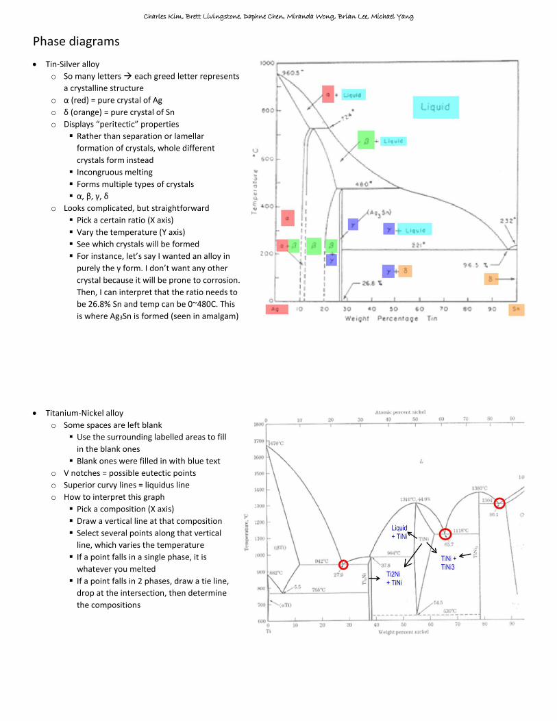
Tin-Silver alloy
o So many letters each greed letter represents
a crystalline structure
o α (red) = pure crystal of Ag
o δ (orange) = pure crystal of Sn
o Displays “peritectic” properties
Rather than separation or lamellar
formation of crystals, whole different
crystals form instead
Incongruous melting
Forms multiple types of crystals
α, β, γ, δ
o Looks complicated, but straightforward
Pick a certain ratio (X axis)
Vary the temperature (Y axis)
See which crystals will be formed
For instance, let’s say I wanted an alloy in
purely the γ form. I don’t want any other
crystal because it will be prone to corrosion.
Then, I can interpret that the ratio needs to
be 26.8% Sn and temp can be 0~480C. This
is where Ag3Sn is formed (seen in amalgam)
Titanium-Nickel alloy
o Some spaces are left blank
Use the surrounding labelled areas to fill
in the blank ones
Blank ones were filled in with blue text
o V notches = possible eutectic points
o Superior curvy lines = liquidus line
o How to interpret this graph
Pick a composition (X axis)
Draw a vertical line at that composition
Select several points along that vertical
line, which varies the temperature
If a point falls in a single phase, it is
whatever you melted
If a point falls in 2 phases, draw a tie line,
drop at the intersection, then determine
the compositions

Charles Kim, Brett Livingstone, Daphne Chen, Miranda Wong, Brian Lee, Michael Yang
Ceramics
Definition
o Ceramic: crystalline, inorganic, non-metallic materials
which consist of metallic and non metallic elements
bonded primarily by ionic and/or covalent bonds
Hand made
Crucial step is the firing step
Note: they are “non-metallic” in the sense that
their mechanical properties are not like metals. It
actually does contain some metal
Ionic/covalent bonds make the material
strong, stiff, and brittle. Very little elastic
deformation
o Glasses: ceramic materials in which the constituents
are heated to fusion and then cooled to a rigid
condition without crystallization
o Dental ceramics are glasses which are filled with
ceramic component
Types of ceramics
o Traditional:
From naturally occurring materials
Clay, feldspar, silica
In dentistry, we use traditional ceramics
o Industrial/engineered:
Al2O3, SiC, B4C, TiO2, SiN
More pure and better mechanical properties
Ceramics are based on chemistry of SiO44-
o Electonegativity of Si is 1.9, and O is 3.4
o This difference in electronegativity is not enough to
be an ionic bond, but too polar to be covalent
o Using math, it is about 50/50
ionic/covalent
o Structurally, SiO4 is a tetrahedron
Polymerization of SiO4
o Si tetrahedron shares 2 oxygens:
forms a chain or ring.
Each subunit is SiO32-
o Si tetrahedron shares 3
oxygens: forms a sheet.
Each subunit is now Si2O52-
o Si tetrahedron shares 4
oxygens: forms a 3D
network called silica
Kaolinite or clay
o Sheet of Si2O52-
o It is negatively charged
o Not stable in nature
o Will need to be neutralized with a positive sheet like
Al2(OH)42 this is kaolinite or clay
o Kaolinite is given the formula Al2SO3*2SiO2*2H2O
Properties of kaolinite/clay
o When it is
moist, the
sheets slide
past each
other and
the material is highly deformable
o When it is dry, there are strong electrostatic
interactions holding the sheets where they are. The
material becomes brittle
Talc
o Like clay, it is a sheet of Si2O52-
o However, the positive sheets
are Mg3(OH)24+
o Talc is given the formula 3MgO*4SiO2*H2O
Silica (SiO2)
o Melts at very high temps (1710 C)
o Used as a filler in ceramics and composites
o Can come in 3 types of crystals, depending on the
temperature they were made in
<573C, 573~867 C: Quartz
867~1470 C: Tridimyte
1710~1470 C: Cristobalite
o Each crystal has a different coefficient of thermal
expansion
o Will not melt during the firing process of a dental
ceramic. Will remain crystallized
Feldspars
o Replaces Si4+ with Al3+
o Since Al only binds 3 O’s,
the network is negatively charged in a network
o Cationic ions like Na, Ca, Ca, Mg, and Ba are added o Low melting point
o Most types of feldspar form an amorphous glass
matrix and poor mechanical properties
o If only some of the Si’s are replaced with Al (called
feldspathic), you get better mechanical properties
(analogous to β grains forming within α grains in
alloys). However, feldspathic is still pretty weak
In dentistry, ceramics involves a mixture of all 3 traditional
ceramics (clay, feldspar, silica)
o Normally, dental ceramics uses very little or no clay
(3~5% max), 20~25% silica as a filler, and the major
component is feldspar
o A composition diagram is used to easily portray how
much of each type of ceramic was used

Charles Kim, Brett Livingstone, Daphne Chen, Miranda Wong, Brian Lee, Michael Yang
Types of casts in dentistry
Pros Cons
Pure Metal
-Strongest -Most conservative
-Ugly
Pure Ceramic
-Esthetic -Biocompatible -High compressive strength -Insulation for pulp
-Brittle (easy crack propagation) -Low fracture toughness -Less conservative -Wears opposing tooth
Metallo-ceramic
-Best of both worlds
How metalloceramic casts are made:
o Paint ceramic on to a metal coping
Note: an opaque ceramic is applied first to hide
the esthetics of the oxidized metal. Then, the
dentin/enamel mimicking porcelains can be
applied for optimal esthetics
o Fire it at 700~1300 C
Sinter the cast in a vacuum to squeeze any pores
(formed by H2O evap) out of the ceramic
Vacuuming ↑ transverse strength
Note: this may cause significant cast shrinkage, so
always make the cast way bigger before firing
o Feldspar in the ceramic fuses to the metal oxide layer
o The cast is now cooled
Fusing temperature
o What do you need to melt anyway?
You want to melt the feldspar
You don’t want to melt the metal, because the
coping will sag. You want to preserve the
structure of the coping
You don’t need to melt the silica or alumina
crystals because you don’t need them to bond to
anything – just provide structural rigidity
o So what temperature is needed?
A dental ceramic contains silica, feldspar, and clay
Structurally, it looks like Si and Al crystals
dispersed in an amorphous matrix of feldspar
It is amorphous because the Na in the feldspar
disrupts complete crystallization
Since it is amorphous instead of crystalline, the
melting temperature of feldspar is low
o Classification of fusing temperature
High fusing: >1300 C (only used in Pt alloys)
Medium fusing: 1100~1300 C
Low fusing: 850~1100 C
Very low fusing: <850 C
In dentistry, the feldspar of choice is leucite
(K2O*Al2O3*4SiO2)
o Note: since leucite incorporates Si as well, it is more
accurate to call it a feldspathic
o Leucite is special because it can crystallize better
mechanical properties
o Also, leucite has a high coefficient of thermal
expansion (CTE). This is good because it makes the
ceramic compatible with metal alloys
Why is leucite used over other feldspars when coating
metal copings? (know this!)
o Has to do with the cooling phase
o Leucite has high coefficient of thermal expansion (α)
o This is desirable as it enhances the metal – ceramic
bond
o Metal α = ceramic α
Theoretically ideal
o Metal α < ceramic α
Ceramic will shrink a lot, whereas metal won’t
shrink as much
Ceramic is held in tension as the metal does not
allow it to shrink much
Ceramic cannot handle tensile stress very well,
and will likely fracture
o Metal α > ceramic α
Metal shrinks a lot, whereas ceramic won’t shrink
as much
Metal cannot shrink too much, so it starts to bend
instead. This causes ceramic to crack
o In real life, it is ideal to have metal α slightly higher
than ceramic α. This way, the ceramic is under slight
compressive stress, which it can handle 1000x better
than tension
Review: 3 criteria for metal-ceramic compatibility
o Oxide layer needs to form on the metal
Titanium oxide layer too thick fractures
Magnesium good thickness of oxide layer
o Tmelting ceramic << Tmelting metal
Make sure the metal coping does not sag when it
reaches the temperature to melt the ceramic
o αmetal > αceramic
All-ceramic casts
o Becoming more popular nowadays
o Many types:
Feldspathic based
Glass-ceramic
Glass-ceramic leucite reinforced
Glass-ceramic other reinforcements
Injection molded glass ceramic
Glass infiltrated alumina/spinell/zirconia core

Charles Kim, Brett Livingstone, Daphne Chen, Miranda Wong, Brian Lee, Michael Yang
All ceramic casts
o Feldspathic based
Glass ceramic
SiO2 crystals
Feldspar amorphous material
K1C (fracture toughness) is low
Glass ceramic with leucite reinforcement
Remember, leucite is a unique feldspar
because it is crystalline instead of
amorphous
When this material is fired, there will be
silica crystals but also leucite crystals
K1C is increased, but not by much
This is also more compatible if you wanted
to bond a ceramic to a metal
Empress – glass ceramic with leucite
Mica – still has feldspathic glass and
refractory silica, but it forms in flakes,
which gives reinforcement. No longer used
Glass ceramic with other reinforcements
Empress II – modifies feldspar with lithium
disilicate will crystallize while allowing
higher Vf better mechanical properties
Emax – also lithium disilicate. However,
manages to push Vf to 70~80% (very high)
o Used in CAD/CAM or presses
o Good for anteriors, not for posteriors
o Crystalline ceramics with glass reinforcement
Uses industrial/engineered ceramics
Much better mechanical properties
Used for large restorations, long span bridges, etc
Made by slip casting
Ceramic is poured into a mold
When the ceramic dries, remove from mold
Then, the ceramic is fired
The ceramic acts as a scaffold. It can be controlled
to have a certain number of pores in the scaffold
Pores are then infiltrated with feldspathic
Makes Vf controllable
Also, feldspathics are transleucent which
gives a natural tooth-like appearance
Vita in-ceram
Uses a ceramic scaffold/core of Al2O3
Spinell in-ceram
Instead of Al2O3, uses MgAlO4
o This is a mixed oxide of 2 metals
Better than Al2O3 (alumina)
Zirconia in-ceram
Al2O3 reinforced with ZnO2
Not pure zirconia
Procera
Uses alumina and zirconia core
Rather than slip casting, uses sintering
Visual for “slip casting”
Properties of zirconia (ZnO2)
o Zirconia liquefies at ~2750 C
o When it cools, it undergoes different crystal
structures
2750C 2370C: cubic crystal
2370C 1170C: tetragonal crystal
<1170: monoclinic crystal
o Turning into the monoclinic form is associated with
4% increase in volume
This shatters the zirconia during cooling
o To prevent shattering, you use 2 strategies:
Add an impurity like MgO, Y2O3, CeO2, CaO
Quench zirconia in the tetragonal form
o Result:
Zirconia is locked in a tetragonal form
The impurities keep it stable in tetragonal form
This state is called partially stabilized zirconia
(PSZ)
o PSZ is pretty cool
When a material cracks, there is a lot of stress at
the tip of the crack which causes elongation
The crack tip has a lot of stress energy
In partially stabilized zirconia, this stress causes
the tetragonal crystal to pop into the monoclinic
form
When it switches to monoclinic, it expands by 4%
The monoclinic crystal at the crack tip now
“rounds off” the crack
Crack can no longer propagate
o Concerns with low temperature degradation
When zirconia is loaded cyclically in a wet
environment, some crystals can turn into
monoclinic form and shatter the ceramic
Also, adjusting the zirconia with a bur may cause
crystals to go monoclinic
Sandblasting, a treatment done before bonding
metals, may not be applicable to zirconia
However, not enough evidence that this happens
in real life

Charles Kim, Brett Livingstone, Daphne Chen, Miranda Wong, Brian Lee, Michael Yang
Applications of zirconia in real life
o Zirconia reinforced alumina has the greatest fracture
strength, despite being brittle
K1C of 8~12
o Zirconia reinforced resin composite
Resin composites have a K1C of 1
This is not enough energy at the crack tip to turn
the tetragonal zirconia into monoclinic
No benefits – useless
o Zirconia reinforced feldspathic
Like composite, no benefit for the same reason
Ceramics – bottom line
o Core can be made of industrial type ceramics
o However, the veneer (surface of the ceramic) must
be a feldspathic ceramic due to esthetic constraints
Visualizing the mechanical properties of ceramics
o Normal distribution patterns
Mean and standard deviation is all you need to
understand the whole distribution pattern
“Mean” is at 50%
Easy to work with
Does not apply to ceramics, because ceramics
behave erratically and have more variation
o Weibull distribution patterns
More fitting for ceramics
Wider distribution more variation
Instead of a “mean” or “SD”, Weibull graphs are
characterized by a characteristic value and
Weibull modulus (i.e. reliability)
The characteristic value is at 63.2%
Weibull graph
o Axes
X axis = stress (in exponential scale)
Y axis = probability of failure
o Important points
When the plot crosses the 63% F line, this
corresponding X value is its flexural strength
The slope is its reliability
o Interpretation of the graph
3 has the highest flexural strength because it
crosses the characteristic value line at ~1000 MPa
1 is the most reliable since it’s the steepest slope
Steeper slope = smaller range of possible
forces that fracture that material
Shallow slope = a wide range of forces can
possibly fracture that material
Slope >10 considered reliabl
o For dentistry purposes, is reliability or flexural
strength more important?
Both are important
Look at flexural strength first. Make sure that it
can withstand forces in the mouth
If all your choices are not limited by their flexural
strength, then look at reliability
Ceramics in bridges
o Looked at the 20 year survival of 3 materials
o A = zirconia with Al 3 unit bridge needs 3+mm connectors
4 unit bridge needs 5+mm connectors
5 unit bridge needs 6+mm connectors
o B = zirconia with Yttrium 3 unit bridge needs 2.5+mm connectors
4 unit bridge needs 4.1+mm connectors
5 unit bridge needs 4.9+mm connectors
o C = lithium disilicate 3 unit bridge needs 3.7+mm connectors
4 unit bridge needs 6+mm connectors
5 unit bridge not possible under 6mm
o Note: 6mm is the limit of practicality in dentistry
o Only zirconia cores can survive 5 unit bridges
But remember, the veneer is just as important as
the core, because the veneer is the esthetic part
Veneers are made of feldspathic
Feldspathic veneers work well in metal ceramic
crowns, since the metal exerts a compressive
force on it, preventing it from fracture
However, when the same ratio of core:veneer is
used in a zirconia core, there is more fracture
Possible reason: zirconia insulates heat while
feldspathic does not. During cooling after drinking
something hot, the feldspathic will shrink a lot
while the zirconia cools slowly. This exerts tensile
stresses
Slow cooling is used to minimize tensile stress on
the feldspathic, so the zirconia and feldspathic
cool at the same rate
However, this means the zirconia isn’t
“quenched” in tetragonal form
Some zirconia will turn monoclinic
expands tensile stress on feldspathic
Not a complete solution to the problem
Although chipping rates are higher in zirconia
core ceramics, it is not as visible

Charles Kim, Brett Livingstone, Daphne Chen, Miranda Wong, Brian Lee, Michael Yang
Computer aided design and machinery (CAD/CAM)
o Computer can mill out a block of material into a
tooth structure to be used as crowns/onlays/inlays
o The block material can be ceramic or composite
Composite Ceramic
-Easy to mill -Hard to mill
-Moderate esthetics -Excellent esthetics
-Cheaper -More expensive
-Fixed with resin, but ↓ strength by 50%
-Also needs to be fixed with resin
o How ceramics are made with in CAD/CAM
Normally, just the “core” part of the ceramic
comes in a block
For example, Emax will come in a green
block of uncrystallised lithium disilicate
Stick it into the machine to mill it
Fire it to crystallize it
Will look ugly, once finished, so apply a veneer
coating of feldspathic on top
3 point bending tests
o Can be used to determine the flexural strength and
the flexural modulus of the ceramic
o Determining flexural modulus (Ef)
o Determining flexural strength (σf)
Formulas differ depending on the cross section of
the object being bent. We’ll use rectangular cross
section with dimensions t x 2c x L
This formula can be manipulated to isolate C. By
isolating C, it tells you the minimum thickness of
the ceramic needed to withstand force F
Assume F = 700N, L = 20 mm, t = 5mm. It is
evident that as the flexural strength (σ) increases,
the thickness needed to withstand 700N force
decreases. Since this is a ^1/2 function, increasing
σ yields diminishing returns
σy (MPa) C (mm)
100 3.24
150 2.65
400 1.62
1000 1.02
You want to minimize C because that means the
least amount of tooth structure can be removed

Charles Kim, Brett Livingstone, Daphne Chen, Miranda Wong, Brian Lee, Michael Yang
Adhesives
Definitions
o Adhesion: intermolecular interactions binding 2
surfaces
With solids it is nearly impossible because it
would require atomic smoothness to bring the
solid atoms towards each other. Also, smooth
surfaces are prone to contamination
Instead, liquids are used which can adapt to the
surface to allow intermolecular interaction. Also
has the benefit of chemical bonding and
mechanical interlocking once the liquid is
solidified
Therefore, adhesives are liquids
o Wetting: adhesion between liquid and solid
Work of adhesion (Wa)
o Energy required to separate the droplet from the
solid surface
o When the droplet is bound to the surface, the energy
holding them together is γSL
o When separated, each surface has an energy γS, γL
o In a dry environment
Wa = (γS + γL) – γSL
Wa > 0 (it takes energy to separate surfaces)
Any liquid will interact, even if it’s a little bit, with
the surface
This gives slight adhesion
Makes Wa always > 0
Increasing γS will increase adhesion
o In a wet environment
Wa = 2γL + 2[Eγ1γ2 - Eγ1γL - Eγ2γL]
The liquid in the environment will compete to
bind to the droplet or the surface
If the liquid has higher affinity for one, it will
separate the layers
So, Wa can be + or –
If Wa is –, then there will be spontaneous
separation
In dentistry, adhesives need to be tested in a wet
environment to make sure that it will not
separate due to water in saliva
Manufacturers will test for 24 hours, but this is
not enough for proper evaluation
30~90 days in water is more suitable
Young’s equation for adhesion
o Don’t need to memorize it, just know the key point
o γ = face surface energy
o For good adhesion, you want θ to be 0o
o If θ is 0o, then cosθ = 1
o Substituting it into the equation, we find that ↑
γSolid and ↓ γLiquid will maximize our wetting
Separation patterns of adhesive and its surface
Work of maximum adhesion (Wa max)
o Combines Wa formula and Young’s formula
o Don’t need to know the math, but by combining both
formulas, we get:
o Wamax = 2γL
o Describes how much “cohesive strength” there is,
AKA how much is needed for cohesive failure
Conclusions/summary
o Molecular contact must be achieved
o Substrata/solid should have high surface energy
o Adhesives/liquid should have low surface energy
o Low contact angle
o High spreading coefficient
o High work of adhesion = good adhesion
o Cohesive strength of the adhesive is the limiting
factor in how well 2 surfaces adhere
o Dry vs wet environments play a role
Steps to achieve adhesion in dentistry
o Pre conditioning – optimizes the surface
characteristics of the substratum
o Priming – ensures substratum compatibility with the
adhesive
o Adhesion – application and curing of the adhesive
layer
Possible substrata
o Enamel
o Dentin
o Metals/alloys
o Ceramics
o Polymers
o Composites
Hybrid layer – resin impregnated layer

Charles Kim, Brett Livingstone, Daphne Chen, Miranda Wong, Brian Lee, Michael Yang
Preconditioning for tooth structure
Enamel Dentin
Properties -95~98% HA -2~5% organics + H2O -Scalloped
-55% HA, 30% collagen -15% H2O -Tubular
What happens when it is etched with acid?
-A layer of HA dissolves, no demineralization -Increases surface area -Creates micro-porosities (50 um) -Exposes high surface energy substratum
-Demineralization of the collagen fibers -Removal of the smear layer (if total etch is used) -5 um demineralized dentin surface -Enlarged tubules -Surface is moist, porous, and low surface energy
Etchants used
-Phosphoric acid (5, 10, 32, 34, 35, 37%) -Maleic acid (10%)
In practice
-Rinse completely -Dry as much as possible
-Don’t etch as long -Rinse completely -Keep it slightly wet so collagen fibers don’t collapse
Preconditioning for dental biomaterials
Metals /alloys
-Acid etch only decontaminates, does not condition -Sandblasted with Al2O3 particles -Considered to “cold work” the metal, so metal properties can change -Rocatec 3M – sandblasting and silica coating -COEJET – sandblasting material
Composites -Sandblasting, like metals -However, material is being removed rather than dimpled like in metals -Make sure not to lose too much material
Traditional ceramics (feldspathic)
-Hydrofluoric acid 4.5~9% -Dissolves glass -Need to protect the patient
Industrial ceramics
-Acid etch only decontaminates -Sandblasting is an option, but not recommended due to monoclinic phase transition of the zirconia
.
Priming
o Goal: make the substratum compatible with
methacrylate (a hydrophobic substance) because it is
the key functional group in any adhesive
o Does not need to be applied on enamel because
enamel already has a high surface energy from
etching
o Dentin primers: HEMA, glutaraldehyde
Dentin is hydrophilic, methacrylate is phobic
HEMA is amphiphilic – allows compatibility
HEMA contains water to “re-fluff” collagen
o Metal primers: tin plating, silicoater
o Ceramic primers: silane
o Time must be given for primer to penetrate layers
o Keep it thin, it does not contribute to strength
o Evaporate the solvent afterwards
Adhesive
o Smooths out the rough surface by filling in porosities
o Too thin = disappears into dentin tubules
o Too thick = like primer, does not contribute to
strength. Has a low γL, so don’t make it thick
otherwise cohesive failure is possible
o Many types: 4-META, PMDM, Phenyl-P, PENTA, MDP,
GPDM, PAMM
o All have a similar structure, where M = methacrylate,
R = spacer, and T = tooth binding group (see below)
Bonding systems
Preconditioner Primer Adhesive -Called “total etch multistep” or “etch and rinse multistep” -Gold standard, outperforms all other systems
Preconditioner Primer + Adhesive -Called “total etch 2 step” or “etch and rinse 2 step” -Most technique sensitive, have to get right amount of H2O
Preconditioner + Primer Adhesive -Called “self etching” or “etch and no rinse” -Has acidic monomer. Not acidic enough to properly etch enamel, but can cause unwanted continued etching -Does not remove the smear layer, it’s incorporated
Preconditioner + Primer + Adhesive -Called “self etching one step system or “all in one” -If adhesive is hydrophobic, then primer can’t contain water to “refluff” the collagen (if there was water, it would separate from the adhesive and the product would be useless) -Since no water, can’t penetrate deep into dentin

Charles Kim, Brett Livingstone, Daphne Chen, Miranda Wong, Brian Lee, Michael Yang
Dental cements